Remote Blower Assembly for Telescoping Downdraft ... Blower Assembly for Telescoping Downdraft...
16
|nstallafion |nstrucfions Remote Blower Assembly for Telescoping Downdraft Ventilation System (I 600cfm) Electrolux
Transcript of Remote Blower Assembly for Telescoping Downdraft ... Blower Assembly for Telescoping Downdraft...

|nstallafion |nstrucfions
Remote Blower Assembly for Telescoping Downdraft Ventilation System(I600cfm)
Electrolux

Fin ing Information
Table of contents
Finding Information ................................................. 2
Important Safety Instructions .................................. 3
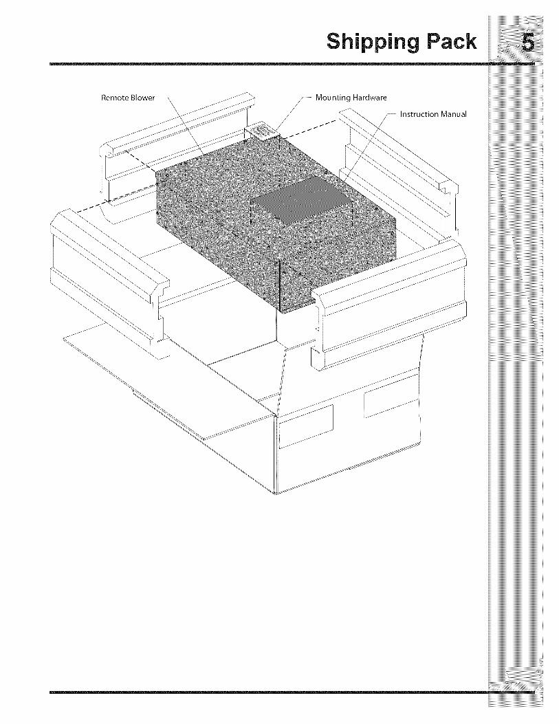
Shipping Pack ......................................................... 5Dimensions ............................................................. 6
Planning .................................................................. 7
Installation of Blower Assembly .............................. 8
Mount Main Housing to Structure ........................... 9Installation on Floor Joists .................................... 10
Installation on Ceiling Joists ................................. 11Installation on Wall Studs ..................................... 12
Installation on Exterior Wall .................................. 13
Electrical Connections .......................................... 14
Verifying Operation and Replacing Cover ............ 15
Warranty ............................................................... 16
This unit is intended for
domestic cooking ONLY.
INSTALLER:
LEAVE INSTRUCTIONS WITHOWNER.
HOMEOWNER:
READ YOUR RETRA CTABLEVENTILATION SYSTEM USE& CARE MANUAL. It contains
important safety informationfor operating this appliance. Italso has many suggestions forgetting the best results from yourretractable ventilation system.
Please read & save this guide
Thank you for choosing Electrolux, the newpremium brand in home appliances. TheseInstallation Instructions are part of our commitmentto customer satisfaction and product qualitythroughout the service life of your new appliance.
We view your purchase as the beginning of arelationship. To ensure our ability to continueserving you, please use this page to recordimportant product information.
Questions?
For toll-free telephone support in the U.S. andCanada:
1-877-4ELECTROLUX (1-877-435-3287)
For online support and Internet production information
visit http://www.electroluxappliances.com
@2012 Etectrolux Home Products, Inc. All rights reserved. Printed in U.S.A.

iiiiiiiiiiiiiiiiiiiiiiiiiiiiiiiiiiiiiiiiiiiiiiiiii_i_;!i;ii:ii:ii:ii:ii:ii:ii:ii:i_:i_!_!i_i_!ii_ii_ii_ii_ii_ii_ii_ii_ii_ii_ii_ii!i!_i_i_ii_ii
important Safety instructions ......3
Wh at yo u need to know a bout sa fe ty inst ructio ns iiiiiiiiiiiiiiiiiiiiiiiiiiiiiiiiiiiiiiiiiiiiiiiiiiiiiiiiiiiiiiiiiiiiiiiiiiiiiiii
Warning and Important Instructions appearing in this guide are not meant to cover all possible conditions iiiiiiiiiiiiiiiiiiiiiiiiiiiiiiiiiiiiiiiiiiiiiiiiiiiiiiiiiiiiiiiiiiiiiiiiiiiiiiiiand situations that may occur. Common sense, caution and care must be exercised when installing, iiiiiiiiiiiiiiiiiiiiiiiiiiiiiiiiiiiiiiiiiiiiiiiiiiiiiiiiiiiiiiiiiiiiiiiiiiiiiiiimaintainingoroperatinganappliance, iiiiiiiiiiiiiiiiiiiiiiiiiiiiiiiiiiiiiiiiiiiiiiiiiiiiiiiiiiiiiiiiiiiiiiiiiiiiiiii
ALWAYS contact your dealer, distributor, service agent or manufacturer about problems or conditions iiiiiiiiiiiiiiiiiiiiiiiiiiiiiiiiiiiiiiiiiiiiiiiiiiiiiiiiiiiiiiiiiiiiiiiiiiiiiiii
youdonotunderstand, iiiiiiiiiiiiiiiiiiiiiiiiiiiiiiiiiiiiiiiiiiiiiiiiiiiiiiiiiiiiiiiiiiiiiiiiiiiiiiii
Recognize Safety Symbols, Words, Labels iiiiiiiiiiiiiiiiiiiiiiiiiiiiiiiiiiiiiiiiiiiiiiiiiiiiiiiiiiiiiiiiiiiiiiiiiiiiiiii
WARNING -- Hazards or unsafe practiceswhich COULD result in severe personal injuryor death.
TO REDUCE THE RISK OF FIRE, ELECTRICSHOCK, OR INJURY TO PERSONS, OBSERVETHE FOLLOWING:• Installation work and electrical wiring must be
,, done by a qualified person(s) in accordancewith all applicable codes and standards,
ii
including fire-rated construction codes andii
standards.• Sufficient air is needed for proper combustion
and exhausting of gases through the flue(chimney) of fuel burning equipment to preventbackdrafting. Follow the heating equipment
ii
manufacturer's guideline and safety standardsii
such as those published by the NationalFire Protection Association (NFPA), and theAmerican Society for Heating, Refrigerationand Air Conditioning Engineers (ASHRAE), andthe local code authorities.
• When cutting or drilling into wall or ceiling, donot damage electrical wiring and other hiddenutilities.
• Ducted fans must always be vented to theoutdoors.
• Use this unit only in the manner intended by themanufacturer. If you have questions, contactthe manufacturer.
• Before servicing or cleaning unit, switchpower off at service panel and lock the servicedisconnecting means to prevent power frombeing switched on accidentally. When the
ii
service disconnecting means cannot be locked,ii
securely fasten a prominent warning device,such as a tag, to the service panel.
::::::::::::::::::::::::::::::::::::::::::::::::::::::::::::::::::::::::::::::::
CAUTION -- Hazards or unsafe practiceswhich iiiiiiiiiiiiiiiiiiiiiiiiiiiiiiiiiiiiiiiiiiiiiiiiiiiiiiiiiiiiiiiiiiiiiiiiiiiiiiii
COULDresultinminorpersonalinjury. iiiiiiiiiiiiiiiiiiiiiiiiiiiiiiiiiiiiiiiiiiiiiiiiiiiiiiiiiiiiiiiiiiiiiiiiiiiiiiii
TO REDUCE THE RISK OF FIRE, ELECTRICSHOCK, OR INJURY TO PERSONS, OBSERVE iTHE FOLLOWING (continued):
;i. Blower must not be installed in a ceilingii ii
_ _ thermally insulated to a value greater than R40.ii ii• Blower must not be installed in furnace
ii ductwork.• To reduce the risk of fire, use only metal
ii ductwork.
i iiiiiiiiiiiiiiiiiiiiiiiiiiiiiiiiiiiiiiiiiiiiiiiiiiiiiiiiiiiiiiiiiiiiiiiiiiiiiiiii iiiiiiiiiiiiiiiiiiiiiiiiiiiiiiiiiiiiiiiiiiiiiiiiiiiiiiiiiiiiiiiiiiiiiiiiiiiii'¸i iiiiiiiiiiiiiiiiiiiiiiiiiiiiiiiiiiiiiiiiiiiiiiiiiiiiiiiiiiiiiiiiiiiiiiiiiiiiii iiiiiiiiiiiiiiiiiiiiiiiiiiiiiiiiiiiiiiiiiiiiiiiiiiiiiiiiiiiiiiiiiiiiiiiiiiiii___i iiiiiiiiiiiiiiiiiiiiiiiiiiiiiiiiiiiiiiiiiiiiiiiiiiiiiiiiiiiiiiiiiiiiiiiiiiiiiiii
iiiiiiiiiiiiiiiiiiiiiiiiiiiiiiiiiiiiiiiiiiiiiiiiiiiiiiiiiiiiiiiiiiiiiiiiiiiiiiiiiii
TO REDUCE THE RISK OF A RANGE TOPii ii
GREASE FIRE:ii ii
ii oNeverleavesu.aceunitsunattendedathighiiiiiiiiiiiiiiiiiiiiiiiiiiiiiiiiiiiiiiiiiiiiiiiiiiiiiiiii _ settings. Boilovers'cause smoking and greasy ...................................................................................ii ii iiiiiiiiiiiiiiiiiiiiiiiiiiiiiiiiiiiiiiiiiiiiiiiiiiiiiiiiiiiiiiiiiiiiiiiiiiiiiiiiiii
spillovers that may ignite. Heat oils slowly on ii __ii
ii • Iowormedium settings, iiiiiiiiiiiiiiiiiiiiiiiiiiiiiiiiiiiiiiiiiiiiiiiiiiiiiiiiiiiiiiiiiiiiiiiiiiiiiiiiiiiiii Alwaysturn hoodONwhen cookingathigh iiiiiiiiiiiiiiiiiiiiiiiiiiiiiiiiiiiiiiiiiiiiiiiiiiiiiiiiiiiiiiiiiiiiiiiiiiiiiiiiiiiii
ii heat or when cooking flaming foods, ii iiii Clean ventilating fans frequently. Grease ii iii should not be allowed to accumulate on fan or ii i
ii ii filter, ii iiiiiiiiiiiiiiiiiiiiiiiiiiiiiiiiiiiiiiiiiiiiiiiiiiiiiiiiiiiiiiiiiiiiiiiiiiiiiiiiiiiiiii Useproperpansize. Alwaysusecookware ii i
ii ii appropriateforthesizeofthesurfaceelement. !! iiiiiiiiiiiiiiiiiiiiiiiiiiiiiiiiiiiiiiiiiiiiiiiiiiiiiiiiiiiiiiiiiiiiiiiiiiiiiiiiiiiii
iiiiiiiiiiiiiiiiiiiiiiiiiiiiiiiiiiiiiiiiiiiiiiiiiiiiiiiiiiiiiiiiiiiiiiiiiiiiiiiiiiiiiiiiiiiiiiiiiiiiiiiiiiiiiiiiiiiiiiiiiiiiiiiiiiiiiiiiiiiiiiiiiiiiiiiiiiiiiiiiiiiiiii

important Safety instructions
_i_i_i_i_i_i_i_i_i_i_i_i_i_i_i_i_i_i_i_i_i_i_i_i_i_i_i_i_i_i_i_i_i_i_i_i_i_i_i_i_i_i_i_i_i_i_i_i_i_i_i_i_i_i_i_i__!__________________________________________
iiiiiiiiiiiiiiiiiiiiiiiiiiiiiiiiiiiiiiiiiiiiiiiiiiiiiiiiiiiiiiiiiiiiiiiiiiiiiiiiiiiiiiiiiiiiiiiiiiiiiiiiiiiiiiiiiiiiiii_i!iiiiiiiiiiiiiiiiiiiiiiiiiiiiiiiiiiiiiiiiiiiiiiiiiiiii_iiiiiiiiiiiiiiiiiiiiiiiiiiiiiiiiiiiiiiiiiiiiiiiiiiiiiiiiiiiiiiiiiiiiiiiiiiiiiiiiiiiiiiiiiiiiiiiiiiiiiiiiiiiiiiiiiiiiiiiiiiiii_i!iiiiiiiiiiiiiiiiiiiiiiiiiiiiiiiiiiiiiiiiiiii_
TO REDUCE THE RISK OF iNJURY TOPERSONS IN THE EVENT OF A RANGE TOPGREASE FIRE, OBSERVE THE FOLLOWING*:
SMOTHER FLAMES with a close-fitting lid,cookie sheet, or metal tray, then turn offthe burner. BE CAREFUL TO PREVENT
BURNS. If the flames do not go outimmediately, EVACUATE AND CALL THE FIREDEPARTMENT.
• NEVER PICK UP A FLAMING PAN - You maybe burned.
DO NOT USE WATER, including wet dishclothsor towels - a violent steam explosion will result.Use an extinguisher ONLY if:A. You know you have a Class ABCextinguisher, and you already know how tooperate it.B. The fire is small and contained in the areawhere it started.
C. The fire department is being called.D. You can fight the fire with your back to anexit.
• Based on "Kitchen Firesafety Tips" published byNFPA.
i iiiiii i!!"
• For general ventilating use only. Do not use toexhaust hazardous or explosive materials andvapors.
• To reduce risk of fire and to properly exhaustair, be sure to duct air outside. Do not ventexhaust air into spaces within walls or ceilingsor into attics, crawl spaces or garages.
• This blower assembly is approved for use withthe following Electrolux Telescoping DowndraftSystems: EI30DD10KSA, EI36DD10KSA,FH30DDSOMSA and FH36DDSOMSA only.Use of this blower assembly with any otherproduct or in any other configuration ishazardous and voids the product warranty.
Consult a licensed ventilation contractor or
qualified technician for proper installation ofexhaust ducting.Locate the cooking area for minimum crossdrafts - away from doors and windows, whenpossible.
• Ducts must be of adequate size and duct runsshould be as short and straight as possible.Where turns are necessary, keep turning radiusas large and smooth as possible.
ii
• The ducting must be air tight. Use a minimumii
of 2 sheet metal screws at every duct joint.Then, seal the duct joints with a high qualityduct tape.
i;• In duct runs less than 10 equivalent straight
feet, the remote blower may interfere with theii
cooktop burner performance due to the highii
volume of air moved. An adjustable damper(not included) should be installed in theducting system. The damper can be adjustedso that proper ventilation and cooktop burnerperformance is achieved.
ii
• Installation of duct work should be carefullyii
planned if it is to go under a concrete slab floor.The duct trench should be boxed to preventcollapse from the wet cement. Be sure to allowroom to run the electrical wiring and conduit.
SAVE T ESE INST UCTIO
FUT E EFE CES
FO
i in Pack

mensions
Specificat!ns__ = and DimensionsRemote Blower Dimensions19-3/4"
Electrical (so.2cm)
Conduit ,\ 19-5/8" MainZonnection \_ (49.8cm) Blower
\\ \\16-15/16" Housing
(43 cm)
9-13/16"(24.9 cm)
/ \,\ \I \/ \ \
1 \\ I
\ \\ /
X \ /
\ _10"(25.4 cm)
16"
(40.6 cm)
Discharge
\\\ [
2-15116" \\ I(7.5 cm) _,,
12-13/16"o
(32.5 cm)
(4)Mount _Points
6-15/16"
(17.6 cm)
oi
16"
(40.6 cm)
1-13/16"
(4.6 cm)
BlowerCover
14"
(35.6 cm)
Discharge
10-5/16"(26.2 cm)
8-3/16"
(20.8 cm)
_'y"'_'_HHHHHHHHHHHHHHHHHHHHHHHHHHHHHHHHHHHHHHH_;;_
Discharge
, Air Inlet
- Duct 10"
30-5/8"
(77.8cm)
30"
(76.2 cm)
3-1/4" (8.3 cm)
4" (10.2 cm)
4-3/4"(12.1 cm)
Adjustable Discharge
List of Included Parts for modelEl16DDPRKS:• (1) Blower
• (4) 1/4" Lag Bolts
Retain all packing and materials until thetelescoping downdraft and all componentshave been installed.
Hardware Needed (userSupplied)• 14 AWG Romex Cable (Min. Size)
Local building codes must be followed in specifyingapproved type and specification of ALL duct used.
All dimensional tolerances are +1/16", -0"unless otherwise stated.
Before starting installation, remove the coverfrom the Blower Main Housing. Check to see ifthe blower wheel turns freely. Do not replace thecover until the installation of the Blower MainHousing is complete.

Planning
Installation PlanningA qualified technician must complete the installationof this appliance.
Carefully check the location where the remote bloweris to be installed. The remote blower should be placedfor convenient access. Make certain that electricalpower can be provided in the selected location.
The Remote Blower can be installed in variouslocations. These Installation Instructions will coversome of the possibilities.
Page1 - On Floor Joists ................................................ 10
2 - On Ceiling Joists ............................................. 11
3 =On Wall Studs ................................................. 12
4 - On Exterior Wall .............................................. 13
DuctworkUse galvanized or aluminum duct in 8"/10" round or3¼"x14" / 4"x14" / 4¾"x14" size, or a combination ofboth, PVC duct should be used if installing under apoured concrete slab, Use the shortest and straightestduct run possible,
Duct Tape OverSeam and Screw
, Air Flow
Screw
IIIIIIIIIIIIIIIIIIIIIIIIIIIIIIIIIIIIIIIIIIIIIIIIIIIIIIIIIIIIIIIIIIIIIIIIIIIIIIIIIII
iiiiiiiiiiiiiiiiiiiiiiiiiiiiiiiiiiiiiiiiiiiiiiiiiiiiiiiiiiiiiiiiiiiiiiiiiiiiiiiiiiiiiiiiiiiiiiiiiiiiiiiiiiiiiiiiiiiiiiiiiiiiiiiiiiiiiiiiiiiiiiiiiiiiiiiiiiiiiiiiiiiiii
iiiiiiiiiiiiiiiiiiiiiiiiiiiiiiiiiiiiiiiiiiiiiiiiiiiiiiiiiiiiiiiiiiiiiiiiiiiiiiiiiii
iiiiiiiiiiiiiiiiiiiiiiiiiiiiiiiiiiiiiiiiiiiiiiiiiiiiiiiiiiiiiiiiiiiiiiiiiiiiiiiiiiiiiiiiiiiiiiiiiiiiiiiiiiiiiiiiiiiiiiiiiiiiiiiiiiiiiiiiiiiiiiiiiiiiiiiiiiiiiiiiiiiiiiiiiiiiiiiiiiiiiiiiiiiiiiiiiiii
DO NOT mount the blower unit by the cover, or byusing any plumbing straps, or by any other methodthan fastening with the lag bolts into solid structural
All ductworks must be as installed as per localWhen mounting the unit, do not warp or bend codes.the housing, or mount in such a manner that theconnected ductwork causes the housing to flex.Verify that the blower wheel spins freely.
When mounting the main blower housing, be sureto fully engage the inlet collar of the blower with theround duct inlet from the downdraft ventilation unit.Secure the outlet to the exhaust duct.
Make sure that there is an appropriate damperinstalled on the discharge ducting, per local code ornational building code, to prevent backflow of air.

Installation of lower Assembly!!!!!!!!!!!!!!!!!!!!!!!!!!!!!!!!!!!!!!!!!!!!!!!!!!!!!!!!!!!!!!!!!!!!!!!!!!!!!!!
Removethe BlowerCoverRemove the Blower Cover from the Main BlowerHousingbyremovingthe(16) silverhexheadscrewsfromtheBIowerCover. Retainthescrews.RemovetheWire boxfromthe Main BlowerHousing
................................................................................by removing the 3 hex head screws. Retain thescrews.
Mount Main HousingThe housing is designed to mount to joist or studson 16" centers. When mounting the Main blowerHousing, the (4)lag bolts must be attached to joists,studs or other structural members.
DO NOT attach the Main Blower Housing directlyto wall board, ceiling panels, or other non-structuralmaterials. Refer to the section drawings on thefollowing pages to determine the proper mounting
DO NOT install the unit so that the unit is supportedby the Blower Cover, Damage to the Blower mayOccur,
Blower
Cover
(16) SilverHex Head Screws
(3) Hex Head Screws
Wire Box

When mounting the Main Blower Housing, the (4)lag bolts must be attached to joists or studs, orother structural members. When mounting the mainblower housing between floor joists or walls studs,it is necessary to space the blower housing off thefloor or wall using a minimum 2x4 wood spacer. Thewood spacers should be properly secured to the joistsor studs. DO NOT secure the wood spacers to thesub-floor or wall materials.
When mounting the main blower housing, be sureto fully engage the inlet collar of the blower with theround duct inlet from the downdraft ventilation unit.Secure the outlet to the exhaust duct.
All duct connections should be sealed with duct tapeand secured with screws.
Connect the Romex cable from the downdraftventilation unit to the main blower housing.
DO NOT mount the main blower housing directly to Before making any electrical connections, verifysub-flooring or wall materials, this will not support that the blower wheel spins freely.the remote b ower housng correct y ...................................................................................................................................................................................................................................................................................................................................................:..................................................................Make the required electrical connections according
to the attached wiring diagram.
When mounting the unit, do not warp or bendthe housing, or mount in such a manner that theconnected ductwork causes the housing to flex.
16"
(40.6 cm)
II
\\\\
' 1/4" Lag Bolts
II
Flooring/ ......
or Wall ....................//
\_ Joist /or Stud
"'_ ...........Main ..........
Blower
Housing
Cross Braceor Cleat
Over 16" Bracket 7(40.6 cm)
//
/,'
II
\\\\\
' 1/4" Lag Bolts
II
Mounting on Joists or Studs Mounting Between Joists or Studs
.... iiiiiiiiiiiiiiiiiiiiiiiiiiiiiiiiiiiiiiiiiiiiiiiiiiiiiiiiiiiiiiiiiiiiiiiiiiiiiiiiiiiiiiiiiiiiiiiiiiiiiiiiiiiiiiiiiiiiiiiiiiiiiiiiiiiiiiiiiiiiiiiiiiiiiiiiiiiiiiiiiiiiiiii
.... iiiiiiiiiiiiiiiiiiiiiiiiiiiiiiiiiiiiiiiiiiiiiiiiiiiiiiiiiiiiiiiiiiiiiiiiiiiiiiiiiii_iiiiiiiiiiiiiiiiiiiiiiiiiiiiiiiiiiiiiiiiiiiiiiiiiiiiiiiiiiiiiiiiiiiiiiiiiiiiiiiiiii
iiiiiiiiiiiiiiiiiiiiiiiiiiiiiiiiiiiiiiiiiiiiiiiiiiiiiiiiiiiiiiiiiiiiiiiiiiiiiiiiiii
.... iiiiiiiiiiiiiiiiiiiiiiiiiiiiiiiiiiiiiiiiiiiiiiiiiiiiiiiiiiiiiiiiiiiiiiiiiiiiiiiiiii_iiiiiiiiiiiiiiiiiiiiiiiiiiiiiiiiiiiiiiiiiiiiiiiiiiiiiiiiiiiiiiiiiiiiiiiiiiiiiiiiiii
.... iiiiiiiiiiiiiiiiiiiiiiiiiiiiiiiiiiiiiiiiiiiiiiiiiiiiiiiiiiiiiiiiiiiiiiiiiiiiiiiiiii_iiiiiiiiiiiiiiiiiiiiiiiiiiiiiiiiiiiiiiiiiiiiiiiiiiiiiiiiiiiiiiiiiiiiiiiiiiiiiiiiiii
.... iiiiiiiiiiiiiiiiiiiiiiiiiiiiiiiiiiiiiiiiiiiiiiiiiiiiiiiiiiiiiiiiiiiiiiiiiiiiiiiiiii_iiiiiiiiiiiiiiiiiiiiiiiiiiiiiiiiiiiiiiiiiiiiiiiiiiiiiiiiiiiiiiiiiiiiiiiiiiiiiiiiiii
.... iiiiiiiiiiiiiiiiiiiiiiiiiiiiiiiiiiiiiiiiiiiiiiiiiiiiiiiiiiiiiiiiiiiiiiiiiiiiiiiiiii_iiiiiiiiiiiiiiiiiiiiiiiiiiiiiiiiiiiiiiiiiiiiiiiiiiiiiiiiiiiiiiiiiiiiiiiiiiiiiiiiiii
.... iiiiiiiiiiiiiiiiiiiiiiiiiiiiiiiiiiiiiiiiiiiiiiiiiiiiiiiiiiiiiiiiiiiiiiiiiiiiiiiiiii_iiiiiiiiiiiiiiiiiiiiiiiiiiiiiiiiiiiiiiiiiiiiiiiiiiiiiiiiiiiiiiiiiiiiiiiiiiiiiiiiiii
.... iiiiiiiiiiiiiiiiiiiiiiiiiiiiiiiiiiiiiiiiiiiiiiiiiiiiiiiiiiiiiiiiiiiiiiiiiiiiiiiiiii_iiiiiiiiiiiiiiiiiiiiiiiiiiiiiiiiiiiiiiiiiiiiiiiiiiiiiiiiiiiiiiiiiiiiiiiiiiiiiiiiiii
.... iiiiiiiiiiiiiiiiiiiiiiiiiiiiiiiiiiiiiiiiiiiiiiiiiiiiiiiiiiiiiiiiiiiiiiiiiiiiiiiiiii_iiiiiiiiiiiiiiiiiiiiiiiiiiiiiiiiiiiiiiiiiiiiiiiiiiiiiiiiiiiiiiiiiiiiiiiiiiiiiiiiiiiiiiiiiiiiiiiiiiiiiiiiiiiiiiiiiiiiiiiiiiiiiiiiiiiiiiiiiiiiiiiiiiiiiiiiiiiiiiiiiiiiii
Spaced 16" Spaced MoreThan16" ....iiiiiiiiiiiiiiiiiiiiiiiiiiiiiiiiiiiiiiiiiiiiiiiiiiiiiiiiiiiiiiiiiiiiiiiiiiiiiiiiiiiii....iiiiiiiiiiiiiiiiiiiiiiiiiiiiiiiiiiiiiiiiiiiiiiiiiiiiiiiiiiiiiiiiiiiiiiiiiiiiiiiiiii

Installation on Floor Joists
Lag Bolts must beattached to joists, studsor structural members.
1/4"Lag Bolts (4) - - .
Conduit / Romex F Flooring/
/
Floor Joist J Discharge
1/4" Lag Bolts (4) ............

Insta on on Ceilin Joists
1/4" Lag Bolts (4)/
Ceiling Joist\\\\\\\\
Discharge
___________i:i_i_i_i_i_i_i_i_i_i_i_i_i_i_i_i_i_i_i_i_i_i_i_i_i_i_i_i_i_i_i_i_i_i_i_i_i_i_i_i_i_i_i_i_i_i_i_i_i_i_i_i_i_i_i_i_i_i_i_i_i_i_i_i_i_i_i_i_i_i_i
_:_iiiiiiiiiiiiiiiiiiiiiiiiiiiiiiiiiiiiiiiiiiiiiiiiiiiiiiiiiiiiiiiiiiiiiiiiiiiiiiiiiiiiiiiiiiiiiiiiiiiiiiiiiii_
\
Conduit / RomexCeiling

Installation on all Studs
Conduit / Romex
Discharge
\\\\
\- 1/4" Lag Bolts (4)
Wall Stud
_i_i_i_i_i_i_i_i_i_i_i_i_i_i_i_i_i_i_i_i_i_i_i_i_i_i_i_i_i_i_i_i_i_i_i_i_i_i_i_i_i_i_i_i_i_i_i_i_i_i_i_i_i_i_i_i__!__________________________________________
iiiiiiiiiiiiiiiiiiiiiiiiiiiiiiiiiiiiiiiiiiiiiiiiiiiiiiiiiiiiiiiiiiiiiiiiiiiiiiiiiiiiiiiiiiiiiiiiiiiiiiiiiiiiiiiiiiiiiii_i!iiiiiiiiiiiiiiiiiiiiiiiiiiiiiiiiiiiiiiiiiiiiiiiiiiiii_iiiiiiiiiiiiiiiiiiiiiiiiiiiiiiiiiiiiiiiiiiiiiiiiiiiiiiiiiiiiiiiiiiiiiiiiiiiiiiiiiiiiiiiiiiiiiiiiiiiiiiiiiiiiiiiiiiiiiiiiiiiii_i!iiiiiiiiiiiiiiiiiiiiiiiiiiiiiiiiiiiiiiiiiiii_

Installation on Exterior all
he OUtdoo We a!h erK! t W K-SP 360 is req uired foro utdoo r! nsta!lation: .....................................................................................................................................................................................................
Conduit / Romex
.........Exterior Wall
, Sealant
-_,=_/
1/4" LagBolts (4)
Outdoor Weather Kit
WK-SP360 (not included)
Blower Cover/
, Zinc Plated/
Phillips Screws/
= J i
Note: Minimum 18"from the ground.
i_i_i_i_i_i_i_i_i_i_i_i_i_i_i_i_i_i_i_i_i_i_i_i_i_i_i_i_i_i_i_i_i_i_i_i_i_i_i_i_i_i_i_i_i_i_i_i_i_i_i_i_i_i_i_i_i_i_i_i_i_i_i_i_i_i_i_i_i_i_i_i_i_i_i_i_i_i_i_i_;i_i_i_i_i_i_i_i_i_i_i_i_i_i_i_i_i_i_i_i_i_i_i_i_i_i_i_i_i_i_i_i_i_i_i_i_i_i_i_i_i_i_i_i_i_i_i_i_i_i_i_i_i_i_i_i_i_i_i_i_i_i_i_i_i_i_i_i_i_i_i_i_i_i_i_i_i_i_i_i_;i_i_i_i_i_i_i_i_i_i_i_i_i_i_i_i_i_i_i_i_i_i_i_i_i_i_i_i_i_i_i_i_i_i_i_i_i_i_i_i_i_i_i_i_i_i_i_i_i_i_i_i_i_i_i_i_i_i_i_i_i_i_i_i_i_i_i_i_i_i_i_i_i_i_i_i_i_i_i_i_;i_i_i_i_i_i_i_i_i_i_i_i_i_i_i_i_i_i_i_i_i_i_i_i_i_i_i_i_i_i_i_i_i_i_i_i_i_i_i_i_i_i_i_i_i_i_i_i_i_i_i_i_i_i_i_i_i_i_i_i_i_i_i_i_i_i_i_i_i_i_i_i_i_i_i_i_i_i_i_i_;i_i_i_i_i_i_i_i_i_i_i_i_i_i_i_i_i_i_i_i_i_i_i_i_i_i_i_i_i_i_i_i_i_i_i_i_i_i_i_i_i_i_i_i_i_i_i_i_i_i_i_i_i_i_i_i_i_i_i_i_i_i_i_i_i_i_i_i_i_i_i_i_i_i_i_i_i_i_i_i_;
// //
/ /
/
f 3-1/4" Duct
f 4"Duct
4-3/4" Duct
,/
,/,/
,//
Bottom ......
Mouting Hole
Hex Head Screws
Vent Slide

Electrical Connections
Make the required electrical connections accordingto the wiring diagram.
Remote Blower Electrical ConnectionLoosen the 3 terminal block screws, insert the leadsfrom the Romex cable into the terminal block and
tighten the screws securing the leads in the terminalblock.
Re-attach the Wire Box using 3 screws.
DOWNDRAFT
CONTROLBOX
P8
Pll
CONTROLBOARD
GND CONTROLHOUSING
I WHTI
GRN
CapacitorI BRN
BLOWERHOUSING
BLK
BLU
GRN
1._=
GND
_i_i_i_i_i_i_i_i_i_i_i_i_i_i_i_i_i_i_i_i_i_i_i_i_i_i_i_i_i_i_i_i_i_i_i_i_i_i_i_i_i_i_i_i_i_i_i_i_i_i_i_i_i_i_i_i__!__________________________________________
iiiiiiiiiiiiiiiiiiiiiiiiiiiiiiiiiiiiiiiiiiiiiiiiiiiiiiiiiiiiiiiiiiiiiiiiiiiiiiiiiiiiiiiiiiiiiiiiiiiiiiiiiiiiiiiiiiiiiii_i!iiiiiiiiiiiiiiiiiiiiiiiiiiiiiiiiiiiiiiiiiiiiiiiiiiiii_iiiiiiiiiiiiiiiiiiiiiiiiiiiiiiiiiiiiiiiiiiiiiiiiiiiiiiiiiiiiiiiiiiiiiiiiiiiiiiiiiiiiiiiiiiiiiiiiiiiiiiiiiiiiiiiiiiiiiiiiiiiii_i!iiiiiiiiiiiiiiiiiiiiiiiiiiiiiiiiiiiiiiiiiiii_
TerminalBlock
©
Romex
Clamp
Romex Cable or
Wiring inMetal Conduit
)
Line
(Black)
Ground(Green/Bare) (White)
Wiring Connection in Remote Blower
Blower Motor
Wiring (Romexor conduit)
Ground (Green)Line (Black)
(White)
WireNuts (3)
Ground
Remote Blower Connection to Vent Control Box

Verifying Operation and placing Cover
Verifying Proper OperationAfter making the required electrical connections,confirm proper operation of the blower.
1. Temporarily re-install the remote blower cover,using 2 screws per side.
2. Turn on the power supply at the circuit breaker.
3. Refer to the Telescoping Down Draft InstallationInstructions for additional instructions on properoperation.
___________i:i_i_i_i_i_i_i_i_i_i_i_i_i_i_i_i_i_i_i_i_i_i_i_i_i_i_i_i_i_i_i_i_i_i_i_i_i_i_i_i_i_i_i_i_i_i_i_i_i_i_i_i_i_i_i_i_i_i_i_i_i_i_i_i_i_i_i_i_i_i_i
_:_iiiiiiiiiiiiiiiiiiiiiiiiiiiiiiiiiiiiiiiiiiiiiiiiiiiiiiiiiiiiiiiiiiiiiiiiiiiiiiiiiiiiiiiiiiiiiiiiiiiiiiiiiii_
DO NOT allow any objects to contact any movingparts or electrical connections while verifying bloweroperation.
Replace the CoverRe-attach the Blower Cover to the Main Blower
housing using the (16) silver hex head screws.
Hex He(ad_siL_e_: _
8 & l • '
iiiiiiiiiiiiiiiiiiiii

Warranty
Your appliance is covered by a one year limited warranty. For one year from your original date of purchase, Electrolux willrepair or replace any parts of this appliance that prove to be defective in materials or workmanship when such appliance is
iiiiiiiiiiiiiiiiiiiiiiiiiiiiiiiiiiiiiiiiiiiiiiiiiiiiiiiiiiiiiiiiiiiiiiiiiiiiiiiiiiiiiiiiiiiiiiiiiiiiiiiiiiiiiiiiiiiiiiiiiiiiiiiiiiiiiiiiiiiiiiiiiiiiiiiiiiiiiiiinstalled, used, and maintainedinaccordancewiththeprovided instructions. Inaddition, theglasscooktoporradiantsurfaceelement of your appliance (excluding built-in and free-standing range appliances)is covered by a two through five year
_!_!_!_!_!_!_!_!_!_!_!_!_!_!_!_!_!_!_!_!_!_!_!_!_!_!_!_!_!_!_!_!_!_!_!_!_!_!_!_!_!_!_!_!_!_!_!_!_!_!_!_!_!_!_!_!_!_!_!_!_!_!_!_!_!_!_!_!_!_!_!_!_!_!_!_!_!_!_!_limited warranty. During the 2nd through 5th years from youroriginal date of purchase, Electroluxwill provide a replacement
g_ass___kt_p_rrad_antsurface___m_ntf_ry_urapp__an__wh__hhaspr_v_nt_b_d_f__tiv__nmat_r_als_rw_rkmansh_p:::::::::::::::::::::::::::::::::::::::::::::::::::::::::::::::::::::::::::::::::::::::::::::::::::::::::::::::::::::::::::::::::::::::::::::::::::::::::::::when such appliance is installed, used, and maintained in accordance with the provided instructions.
Exclusions
This warranty does not cover the following:
1. Products with original serial numbers that have been removed, altered or cannot be readily determined.2. Product that has been transferred from its original owner to another party or removed outside the USA or Canada.3. Rust on the interior or exterior of the unit.
4. Products purchased "as-is" are not covered by this warranty.5. Products used in a commercial setting.6. Service calls which do not involve malfunction or defects in materials or workmanship, or for appliances not in
ordinary household use or used other than in accordance with the provided instructions.
7. Service calls to correct the installation of your appliance or to instruct you how to use your appliance.8. Expenses for making the appliance accessible for servicing, such as removal of trim, cupboards, shelves, etc.,
which are not a part of the appliance when it is shipped from the factory.9. Service calls to repair or replace appliance light bulbs, air filters, water filters, other consumables, or knobs,
handles, or other cosmetic parts.
10. Labor or in-home service costs during the additional limited warranty periods beyond the first year from youroriginal date of purchase.
11. Pickup and delivery costs; your appliance is designed to be repaired in the home.12. Surcharges including, but not limited to, any after hour, weekend, or holiday service calls, tolls, ferry trip charges,
or mileage expense for service calls to remote areas, including the state of Alaska.
13. Damages to the finish of appliance or home incurred during transportation or installation, including but not limitedto floors, cabinets, walls, etc.
14. Damages caused by: services performed by unauthorized service companies; use of parts other than genuineElectrolux parts or parts obtained from persons other than authorized service companies; or external causes such
as abuse, misuse, inadequate power supply, accidents, fires, or acts of God.
DISCLAIMER OF IMPLIED WARRANTIES; LIMITATION OF REMEDIES
CUSTOMER'S SOLE AND EXCLUSIVE REMEDY UNDER THIS LIMITED WARRANTY SHALL BE REPAIR OR
REPLACEMENT AS PROVIDED HEREIN. CLAIMS BASED ON IMPLIED WARRANTIES, INCLUDING WARRANTIESOF MERCHANTABILITY OR FITNESS FORA PARTICULAR PURPOSE, ARE LIMITED TO ONE YEAR OR THESHORTEST PERIOD ALLOWED BY LAW, BUT NOT LESS THAN ONE YEAR. ELECTROLUX SHALL NOT BE LIABLEFOR CONSEQUENTIAL OR INCIDENTAL DAMAGES SUCH AS PROPERTY DAMAGE AND INCIDENTAL EXPENSESRESULTING FROM ANY BREACH OF THIS WRITTEN LIMITED WARRANTY OR ANY IMPLIED WARRANTY. SOMESTATES AND PROVINCES DO NOTALLOW THE EXCLUSION OR LIMITATION OF INCIDENTAL OR CONSEQUENTIAL
DAMAGES, OR LIMITATIONS ON THE DURATION OF IMPLIED WARRANTIES, SO THESE LIMITATIONS OREXCLUSIONS MAY NOTAPPLY TO YOU. THIS WRITTEN WARRANTY GIVES YOU SPECIFIC LEGAL RIGHTS. YOUMAYALSO HAVE OTHER RIGHTS THAT VARY FROM STATE TO STATE.
If You Need Service
iiiiiiiiiiiiiiiiiiiiiiiiiiiiiiiiiiiiiiiiiiiiiiiiiiiiiiiiiiiiiiiiiiiiiiiiiiiiiiiiiiiiiiiiiiiiiiii%_i_i_i_i_i_i_i_i_i_i_i_i_%Keep your receipt, delivery slip, or some other appropriate payment record to establish the warranty period should servicebe required. If service is performed, it is in your best interest to obtain and keep all receipts. Service under this warrantymust be obtained by contacting Electrolux at the addresses or phone numbers below.
This warranty only applies in the USA, Puerto Rico and Canada. In the USA and Puerto Rico, your appliance is warrantedby Electrolux Major Appliances North America, a division of Electrolux Home Products, Inc. In Canada, your applianceis warranted by Electrolux Canada Corp. Electrolux authorizes no person to change or add to any obligations under thiswarranty. Obligations for service and parts under this warranty must be performed by Electrolux or an authorized service
company. Product features or specifications as described or illustrated are subject to change without notice.
USA
1.800.944.9044
Electrolux Home Products, Inc.,
10200 David Taylor Drive
Charlotte, NC 28262
Canada1-800-265-8352
Etectrolux Canada Corp.5855 Terry Fox WayMississauga, Ontario, Canada L5V 3E4