REMEDIAL INVESTIGATION/FEASIBILITY STUDY · The objective of the remedial investigation/feasibility...
99
r fl I: L - * - 00136 EPA Region 5 Records Ctr. 208433 WORK PLAN REMEDIAL INVESTIGATION/FEASIBILITY STUDY CEMETERY SITE MICHIGAN DEPARTMENT OF NATURAL RESOURCES DEPARTMENT PURCHASE ORDER CONTRACT NUMBER 1525 E.G. JORDAN PROJECT NUMBER 4465-40 C SEPTEMBER 1984 E.G. JORDAN CO. 9.84.2 0001.0.0
-
Upload
truongtuong -
Category
Documents
-
view
228 -
download
0
Transcript of REMEDIAL INVESTIGATION/FEASIBILITY STUDY · The objective of the remedial investigation/feasibility...

r
flI:
L
- * - 00136EPA Region 5 Records Ctr.
208433
WORK PLAN
REMEDIAL INVESTIGATION/FEASIBILITY STUDY
CEMETERY SITE
MICHIGAN DEPARTMENT OF NATURAL RESOURCES
DEPARTMENT PURCHASE ORDER
CONTRACT NUMBER 1525
E.G. JORDAN PROJECT NUMBER 4465-40
CSEPTEMBER 1984
E.G. JORDAN CO.
9.84.20001.0.0

EC JORDAN CQCONSULTING ENGINEERS
4465-40
September 12, 1984
Ms. Deborah D. LarsenRemedial Action SectionGroundwater Quality DivisionDepartment of Natural ResourcesStevens T. Mason Building .Corner of Pine & Alleganey StreetsLansing, MI 48909
Dear Debbie:
Subject: Cemetery SiteWork Plan
Enclosed are six copies of the Cemetery Site Work Plan which have beenprepared in accordance with your letter of August 3, 1984 and oursubsequent conversations. We are now preparing a Quality AssuranceProject Plan (QAPP) for the Cemetery Site. The QAPP should be completedand submitted for your review by September 24, 1984. The field pro-cedures proposed in the Work Plan and QAPP are the same as those beingused at the Rose Township (Demode Road) Site.
Once you and other DNR officials have had an opportunity to review thisWork Plan, we would be pleased to meet with you to discuss the program.In the meantime, if you have any questions concerning this material,please contact Jim Dragun or me.
Sincerely yours,
E.G. JORDAN CO.
James S. Atwell, P.E.ManagerSolid/Hazardous Waste Services
JSA:mjw RECEIVED
SEP 1 3 1994Enclosures
-QD-PEMED'AL ACTION
17515 WEST NINE MILE ROAD • SUITE 225 • SOUTHFIELD, MICHIGAN 48075 • (313) 569-3955PORTLAND, ME • BOSTON, MA • WASHINGTON, DC • TALLAHASSEE, FL

TABLE OF CONTENTS
SECTION TITLE PAGE NO.
1.0
2.0
WORK PLAN SUMMARY 1
1.1 PROBLEM STATEMENT 11.2 OBJECTIVES 21.3 SCOPE OF WORK 31.4 BUDGET 51.5 SCHEDULE 6
PLAN SCOPE OF WORK 7
2.1 INTITAL ACTIVITIES (PHASE" I) 7Task 1: Prepare Work Plan 7Task 2: Describe Current Situation 8Task 3: Prepare Safety Plan 10Task 4: Define Bqundary Conditions 11Task 5: Preinvestigative Evaluation 11Task 6: Site Office 13Task 7: Community Relations 14
2.2 FOCUSED FEASIBILITY STUDY (PHASE II) 15Task 8: Geophysics 15Task 9: Pollutant Characterization 20Task 10: FSS - Remedial Action Evaluation . . 21
2.3 REMEDIAL INVESTIGATION (PHASE III) 22Task 11: Air Investigation 22Task 12: Domestic Well and Existing Monitoring
Well Sampling 25Task 13: Surface Water/Sediment Sampling. . . 25Task 14: Monitoring Well Installation . . . . 26Task 15: Surface Soils 32Task 16: New Monitoring Well Sampling . . . . 35Task 17: Aquifer Testing 37Task 18: Analytical Program 38Task 19: Data Interpretation/Contamination
Assessment 38Task 20: RI Report 43
2.4 FEASIBILITY STUDY (PHASE IV) 44Task 21: Description of Current Situation
and Scoping Update 44Task 22: Development of Alternatives 44Task 23: Initial Screening of Alternative . . 49Task 24: Laboratory Studies (Optional). . . . 51Task 25: Detailed Evaluation 51Task 26: Evaluation and Recommendation of
Most Cost-Effective Alternative. . . 57
9 .84. 20002.0.0

I:
L
I
SECTION
TABLE OF CONTENTS (cont.)
TITLE PAGE NO.
3.0
4.0
Task 27: Interim Report . .Task 28: Conceptual Design.Task 29: Final Report . . .
MANAGEMENT PLAN
3.1 PROJECT ORGANIZATION3.2 PROJECT MANAGEMENT .
COST AND SCHEDULE
4.1 PROJECT SCHEDULE4.2 COST ANDS BUDGET
APPENDIX A - ADDITIONAL RESUMES
596164
65
6567
70
7072
9.84.20003.0.0
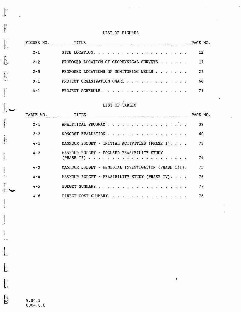
LIST OF FIGURES
FIGURE NO. TITLE PAGE NO.
I2-1
2-2
2-3
3-1
4-1
TABLE NO.
2-1
2-2
4-1
4-2
4-3
4-4
4-5
4-6
SITE LOCATION 12
PROPOSED LOCATION OF GEOPHYSICAL SURVEYS 17
PROPOSED LOCATIONS OF MONITORING WELLS 27
PROJECT ORGANIZATION CHART 66
PROJECT SCHEDULE 71
LIST OF TABLES
TITLE PAGE NO.
ANALYTICAL PROGRAM . 39
NONCOST EVALUATION 60
MANHOUR BUDGET - INITIAL ACTIVITIES (PHASE I). ... 73
MANHOUR BUDGET - FOCUSED FEASIBILITY STUDY(PHASE II) 74
MANHOUR BUDGET - REMEDIAL INVESTIGATION (PHASE III). 75
MANHOUR BUDGET - FEASIBILITY STUDY (PHASE IV). ... 76
BUDGET SUMMARY 77
DIRECT COST SUMMARY 78
LIL
9 . 84. 20004.0.0

1.0 WORK PLAN SUMMARY
1.1 PROBLEM STATEMENT
The Cemetery Site is located off the North Milford Road in Rose Township,
Oakland County, Michigan. Based on citizen reports, it is alleged that approxi-
mately 500 'barrels were dumped at the Cemetery Site in the late 1960's or early
1970's by the same hauler who disposed of wastes at the Rose Township (DeMode
Road) and Springfield Township Dump Sites in Oakland County.
In September, 1981 a barrel excavation program was undertaken at the Cemetery
Site. At that time approximately 20 to 30 barrel fragments were excavated and
transported off-site for disposal. Samples of the barrel contents were col-
lected and analyzed. Analyses indicted the presence of paint sludges, sol-
vents, polychlorinated biphenyls and oils.
A description of the site and the levels of contamination found at the site to
date are presented in the final Remedial Action Master Plan (RAMP) for the
Cemetery Site dated April 14, 1984 which was prepared for the U.S. Environ-
mental Protection Agency (USEPA) by the firm of CH2M Hill. However, at the
present time there is very limited data available describing the nature of the
waste deposit at the Cemetery Site. The tasks described in this Work Plan will
define the nature of the waste deposit, assess the threat to public health and
the environment, and identify the cost-effective remedial action for the site.
9.84.20005.0.0

I
1.2 OBJECTIVES
The objective of the remedial investigation/feasibility study (RI/FS) at the
Cemetery Site is to undertake studies which will determine the nature and
extent of the environmental contamination at the site, the public health and
environmental hazard posed by the site and to identify a cost-effective,
environmentally sound and socially acceptable remedial program for the site.
In addition, the Cemetery project includes a Focused Feasibility Study (Phase
II of this Work Plan) which will study the existing exposure threat to public
health and the environment, establish the need to implement initial remedial
measures to control the release of contaminants, and identify the cost-effec-
tive initial remedial measure.
Following is a summary of several of the specific objectives which will be
addressed by the RI/FS.
1. Determination of the nature and extent of contamination on the project
site.
2. Definition of public health hazards or environmental problems related to
on-site waste disposal.
3. Development of a Focused Feasibility Study (FFS) describing a limited
number of phased remedial alternatives to control contaminants on the site
which pose imminent threats to public health or the environment.
9.84.20006.0.0

4. Determination of the means to reduce the potential for possible direct
contact with contaminated soil and hazardous materials by the public.
5. Definition of pathways of contaminant migration from the site as well as
the impact of contaminants on potential receptors.
jbfc 6. Definition of on-site features which could affect contaminant migration,
containment, or cleanup.
7. Identification of viable remedial action alternatives.
8. Evaluation of remedial action alternatives.
9. Recommendation of an appropriate remedial program for the site.
10. Preparation of a conceptual design for the selected alternative.
11. Assisting the Michigan Department of Natural Resources (DNR) with its
community relations efforts for the site.
3 SCOPE OF WORKII' *>t The Work Plan for the Cemetery Site has been developed based on information
provided with the Request for Work Plan and data in the RAMP for the site. In
ti developing the Work Plan we have divided the scope of work into 4 major phases
9.84.20007.0.0

^ and 29 separate tasks which are presented in Section 2.0. The organization of
the Work Plan in this manner is different from that presented in the Request
for Work Plan. However, each of the work elements identified in the Request
[ for Work Plan are included in the 29 tasks which make up this Work Plan. For
, purposes of this Work Plan we have placed those tasks which are directly
' associated with the FFS into a separate phase of work. Even though the FFS has
S been identified as a separate phase, it should be understood that the field
data gathering activities associated the^FFS that are closely related to the
(• f field activities associated with the RI will be ongoing concurrently. In
,;..- addition, the field data gathered during the FFS will be utilized in the RI.
("_'
) Several assumptions have been made in preparing this work plan. They are:
|y o DNR will provide a topographic survey of the Cemetery site;
F-1 o DNR will provide rights of entry and access to the site for purposes of
[.;" conducting the RI/FS;
[;'<: o DNR will provide telephone services for the site office;
(- o on the basis of a preliminary evaluation of available data, Level D
!"" protection will be used for most on-site work (The exception to the use of
Level D protection involves the soil and waste sampling in the test pit
| { excavations during Task 9 which will be conducted at Level C. The level
of protection is subject to modification on the basis of air monitoring
t ; conducted during the initial phases of on-site work. If air monitoring
9.84.20008.0.0

results indicate that a potential respiratory hazard exists or wastes are
encountered which pose dermal contact hazards, additional protection may
be required over and above that proposed above. Higher levels of protec-
tion which may be required would result in adjustments to cost and sched-
ules);
the area of investigation will be limited to the immediate vicinity of the
site (The residential well survey wiJLl involve the collection of water
samples from wells within approximately 1,000 feet of the site);
the RI/FS will evaluate and use available data obtained during previous
investigations on-site; and
the cost of analytical services are not included in the total cost for the
RI/FS. It is assumed that the analysis of environmental samples gathered
in the remedial investigation will be performed through the USEPA Contract
Laboratory Program (CLP) and/or other laboratories designated by DNR.
£i
m 1.4 BUDGET
&
1 The level of effort (manhours) required for each of the four phases of the
Cemetery Project is as follows:
9.84.20009.0.0
Phase 1 - Initial Activities: 832 Hours
Phase 2 - Focused Feasibility Study: 1160 Hours
Phase 3 - Remedial Investigation: 2040 Hours
Phase 4 - Feasibility Study: 1820 Hours
A total of 5852 manhours will be required for the project. The total for Phase
IV, Feasibility Study, does not include manhours needed to perform any labora-
tory or field studies which may be required (Optional Task 24). The manpower
estimates for these studies will be determined during the preparation of the
laboratory study work plan, if one is required. The manhour and cost estimates
for the project are presented in Section 4.0.
1.5 SCHEDULE
It is estimated that the Cemetery Project will take 16 months to complete
following approval of the work plan and authorization to begin work. This
schedule assumes that many of the field activities will be conducted during the
winter months. The FFS will be completed 5 months after approval of the Work
Plan. The project schedule has been developed assuming a 60 day turnaround for
analytical results from the USEPA Contract Laboratory Program. In addition,
the USEPA and DNR review time for draft and final reports is estimated at one
to three weeks as specified in the schedule. The detailed schedule is pre-
sented in Section 4.0.
9.84.20010.0.0

2.0 PLAN OF WORK
p-;fe- 2.1 INTITAL ACTIVITIES (PHASE I)
A total of seven tasks have been identified for Phase I, Initial Activities.
Task 1: Prepare Work Plan
A Work Plan and a Quality Assurance Project Plan (QAPP) will be prepared for
the Cemetery Site Remedial Investigation/Feasibility Study (RI/FS). The work
plan will describe:
o the initial activities to be undertaken prior to the RI/FS;
o the tasks to be completed during the Focused Feasibility Study to identify
i 1) the need to implement a source control remedial action prior to final
site remediation, and 2) the cost-effective source control remedial
| alternative, if necessary;
o the tasks to be completed during the RI to establish the nature and extent
! of contamination; andI.
j " .
I o the tasks to be completed during the FS which will lead to the selection
, of a cost-effective remedial alternative for the site.
9.84.20011.0.0

The QAPP will describe the procedures to be used in the collection of samples,
generation of data and assessment of data during the project to assure that
valid, appropriate methods are consistently applied toward achieving project
objectives. The QAPP will acknowledge that the laboratory analyses will not be
performed by Jordan. Laboratory QA/QC will be the responsibility of others.
Task 2: Describe Current Situation
The objective of Task 2 is to prepare an up-to-date description of the condi-
tions currently existing at the site. This description will be accomplished
through a detailed site reconnaissance by key members of the project team and a
thorough review and compilation of available site data. During the site
reconnaissance, air quality measurements and other observations will be made
for the purpose of confirming the appropriate level of safety for the site.
During the initial site reconnaissance, the provisions of Jordan's Corporate
Health and Safety Plan will be in effect for Jordan team members.
Based on our discussions with DNR, the final RAMP (April 14, 1984) and other
supporting data provided by DNR contains most of the information available on
the Cemetery Site. We have found that it is valuable to compile all available
site data, including the input from our site reconnaissance, into a single
source.
During the site reconnaissance, the location of most sampling points will be
finalized.
9.84.20012.0.0
The description of the current situation will be presented in a brief report
> with appropriate appendices which will compile site data into a single source.
The report will include the use of graphics to present a clear, concise des-i.'! '
I cription of site conditions. It is not the intent of this report to reiterate
,. data presented in the RAMP and other reports. This report will comparei/1 recently gathered data with earlier data to determine if any of the earlier
r conclusions on the site require modification. The report will address the£ -:'•
following items: ,
(;..;• a. Site Background. Site background has been summarized in the RAMP. If any
new information is uncovered during Jordan's site reconnaissance or data
| • review, it will be included in the Task 2 report and its effect on the under-
standing of the site conditions will be reviewed.
I
r b. Nature and Extent of Problem. The nature and extent of the materials
deposited on the site has been reviewed in the RAMP. Data developed during
f- Jordan's site reconnaissance will be reviewed to determine if it is consistent
with the data presented in the RAMP. The new data and any adjustments to the
description of the nature and extent of the problem will be included in the
Task 2 report.
In defining the nature and extent of the problem, waste characterization and
analytical data from the Springfield and Rose Township (Demode Road) sites will
be utilized since the same waste hauler reportedly disposed of similar wastes
at the Cemetary Site. This data is expected to be a principal source of
information for the site inventory of known pollutants, including wastes in the
9.84.20013.0.0

drums reportedly buried at the site. This information will be utilized in
planning the geophysical investigation and pollutant characterization included
in the FFS (Phase II).
Task 3; Prepare Safety Plan
Jordan will make an initial assessment of the potential hazards associated with
the Cemetery site from information currently available. Based on the Master
Site Health and Safety Plan developed by DNR, Jordan will then develop a health
and safety plan which is consistent with:
o Section lll(c)(6) of CERCLA;
I-:.- o EPA order 1440.1 - Respiratory Protection
o EPA order 1140.3 - Health and Safety Requirements for Employees Engaged in
[ Field Activities;
f o EPA Occupational Health and Safety Manual;
i
' o EPA Interim Standard Operating Safety Procedures and other EPA guidance as
f developed by EPA;
ii o Michigan Occupational Safety and Health Act; and
I
L
o Site conditions.
10
9.84.20014.0.0

During the initial site visit and ongoing site work, monitoring equipment will
be used to determine whether levels of organic vapors .are present at poten-
tially hazardous exposure levels. The on-going generation of data will be
'• evaluated and the safety plan updated as required. The basis for hazard level-
determination, personnel protective gear, decontamination, site safety facili-
• ties and contingency plans for the Cemetery site will be discussed in detail.
All data generated will be provided to DNR to assist in comprehensive safety
planning activities.
W
Task 4: Define Boundary Conditions
Site investigation boundaries will be set so that the subsequent investigations
will be limited in areal extent and yet cover areas of potential contamination
in sufficient detail to support the FS. Preliminary site investigation bound-
aries have been assumed in the preparation of the work plan (see Figure 2-1).
These boundaries will be modified, if necessary, during the site reconnais-
sance.
Task 5: Preinvestigative Evaluation
•-•-' Based on information developed during Task 2 (Description of Existing Condi-
i tions), a list of potential remedial technologies and remedial alternatives
will be prepared for review by DNR and EPA. By identifying potential remedial
/..:.- alternatives at this time, it will be possible to review the FFS and RI tasks
to be certain that adequate information will be developed to allow the FFS and
* -•••• FS to be properly completed.
Lli
119.84.20015.0.0

j
I
LEGEND
plil APPROXIMATE AREA OFJ BURIED DRUMS
DOMESTIC WELL
EXISTING MONITORING WELL
ROSETOWNSHIPCEMETERY
10 200 1400 FEET
FIGURE 2-1'SITE LOCATION
CEMETERY SITEMICHIGAN DEPARTMENT
OF NATURAL RESOURCES
ECJORDAMCQ •

m
Task 6: Site Office
A site office will be established for the duration of the on-site investiga-
tions for use by Jordan and DNR staff. The site office will provide office
space and space for staging, equipment preparation, sample handling and stor-
age. Level D safety procedures are anticipated for most site activities,
therefore an isolated decontamination facility is not anticipated to be re-
quired. Decontamination and sanitary facilities will be located outside,
adjacent to the site office.
The project costs presented in Section 4.0 of this Work Plan include:
o site office;
o portable toilet;
o electrical service;
o decontamination facilities; and
o temporary fencing to restrict access to the active site area.
o site access improvements
o temporary fencing
Based on the nature of this site, it is proposed that temporary fencing be used
to delineate the active project area and to discourage site access. Extensive
site fencing and control gates are not proposed for this project.
13
9.84.20016.0.0

Task 7: Community Relations
fThe community relations program for the Cemetery site will be conducted by DNR
ft! with support from the E.C. Jordan Co. The remedial action task force which has
p- been established for the nearby Rose Township (Demode Road) site will be the
focal point for the Community Relations program for the Cemetery Site. Inr .-kl- addition, a separate community relations effort will be developed by DNR forL -',
the residents located near the site. Jordan is prepared to provide support in
the following areas, as directed:
o meet with local officials to determine their concerns and community
relations needs;
o periodically brief local and county officials regarding current activities
during the on-site activities;
t .o provide information for press releases during the remedial investigation/
feasibility study; and
o prepare information to be presented at public meetings.
Community relations activities will be ongoing during the entire project.
14
9.84.20017.0.0

2.2 FOCUSED FEASIBILITY STUDY (PHASE II)
I-"i :
The Focused Feasibility Study (FFS) includes three separate tasks. The FFS
iffc. will be initiated based on data which is currently available in addition to any
f- new data which is developed during Task 2. The objective of the FFS is to:
1) more clearly define the areas, if any, where drums are present at the
f Cemetery Site, 2) determine, in a general way, what the contents of the drums
are, and 3) establish the need for a phased approach to remedial action to
'W' control the release of contaminants prior to the implementation of a remedial
action for the entire site. The following information describes the tasksi -i ,
associated with the FFS.
Ii
Task 8: Geophysics
The first task of the FFS is the geophysical investigation. The scope and
objectives of the geophysical investigation are as follows:
L- Wo Metal Detector/Magnetometer. A metal detector/magnetometer survey is
i :; proposed to locate areas of buried drums that might exist at the site. A
general magnetometer survey is proposed for approximately 8 acres. A morei.' detailed magnetometer/metal detector survey is proposed for a 3 to 4 acre
i area.L '-.
[ . o Electrical Resistivity. Electrical resistivity methods will be used to
, assess subsurface geologic conditions at the site and vicinity, particu-
larly the thickness and areal extent of shallow clayey layers in granular
I15
9.84.20018.0.0
material and the depth to the "hard pan" or till layer that exists beneath
the site. Resistivity may be useful to delineate a groundwater plume
which may be present beneath the site if inorganic ions are present in
subsurface soils and/or groundwater.
o Ground Penetrating Radar (GPR). A limited GPR program is proposed as a
contingency to determine the depth and'volume of buried drums if such
further definition of subsurface conditions is required subsequent to the
metal detector/magnetometer survey.
•a. Metal Detector/Magnetometer Survey. Drums containing hazardous materials
are reported to be buried at the Cemetery site. Where the drums have been•
exposed at the surface, evidence of severe corrosion has been reported. The
buried drums, based on available data, appear to be in a localized area (Figure
2-2). Although buried materials have not been previously found in the western
portion of the site, the area is open and accessible by roads and could have
tentially been used as a disposal area in the past.
A metal detector will be used to scan up to 8 acres of the site. The scan will
consist of a survey of continuous readings along parallel lines 10 feet apart
throughout an 8-acre area. Jordan recognizes that a solitary buried barrel has
a small but finite potential to be missed with such a grid pattern. Clusters
of barrels represent the principal target of the program. Areas having anoma-
lous magnetic gradients will then be surveyed in greater detail with a metal
detector and/or magnetometer (a 10-foot or 5-foot grid) to delineate subsurface
16

ROSETOWNSHIPCEMETERY
LEGEND
APPROXIMATE AREA OFtt&i&fl BURIED DRUMS
DOMESTIC WELL
EXISTING MONITORING WELL
PROPOSED AREA OFGEOPHYSICAL SURVEY
J200
FIGURE 2-2PROPOSED LOCATION OF GEOPHYSICAL SURVEYS
(METAL DETECTOR/MAGNETOMETER AND RESISTIVITY)CEMETERY SITE
_ MICHIGAN DEPARTMENT|4oo FEET OF NATURAL RESOURCES
ECJCRDANCQ

conditions more completely. The metal detector/magnetometer will be used to
||' refine the vertical and areal extent of the buried wastes.
«£• The initial phase of field measurements will cover an area of approximately 8
p acres as shown in Figure 2-2. It is estimated that the detailed portion of thei
survey will be conducted in an area of approximately two acres. The area
fsP identified in Figure 2-2 is subject to modification on the basis of the site
, reconnaissance visit to be made as part of Task 2. Positive indication of
£.:. ^ buried metallic material will be verified by backhoe as part of Task 9.
jr.; Sampling and analysis of identified buried wastes will be done as part of Task
9 and will take place prior to conducting subsurface explorations as part of
k the RI. The metal detector/magnetometer survey will be conducted by Jordan.
'- b. Electrical Resistivity Survey. On the basis of previous studies, it
; appears that the subsurface conditions at the Cemetery site consist of discon-
tinuous silt/clay layers in granular glacial deposits. Geologic conditions
[" w , appear to be somewhat complex (i.e., discontinuous layering, variable condi-t' L
tions in both horizontal and vertical directions) and may or may not be suitediI for characterization by resistivity methods. Therefore, the survey will be
{ conducted in a phased manner, i.e., the results of initial measurements will
determine if the full 3-day program is carried out. We propose to conduct a
series of approximately 20 vertical electrical soundings in the area shown in
Figure 2-2. No soundings will be made in buried waste areas identified by the
L. magnetometer survey due to the fact that the metal barrels will interfere with
i the survey.
I.
I18
9.84.20020.0.0

A Keck Model No. IL-69 electrical earth resistivity instrument will be used at
[ the site. The principal objectives of the resistivity survey are to ascertain
the thickness and areal extent of subsurface clayey layers and determine the
{*: depth to the till layer. A secondary objective is to ascertain the presence of
. a groundwater plume, that is, high concentrations of dissolved inorganic
' materials in groundwater. Since clayey layers tend to retard and redirect the
I downward percolation of precipitation and dissolved waste material, it is
important to understand the extent of their presence in the subsurface. TheI .[. f results of the resistivity survey will influence the location of soil sampling
r- points and the location of monitoring wells. The resistivity survey will be
Pconducted by Keck with support from Jordan.
c. Ground Penetrating Radar (GPR). Subsequent to the metal detector/magnet-I .'| ometer survey, a limited GPR survey consisting of 2 days of profiling is
; proposed to further define the location of buried drums. The GPR survey may oriI1 may not be required depending on the quality of previous data. This survey
will only be made in the area of identified anomalies as determined by thei W
metal detector/magnetometer survey. The principal objective of the survey is
to determine the depth and areal extent of the buried waste so that a prelimi-
nary estimate of the volume of buried waste can be made. The costs associated;*,
with the proposed GPR program have been included in the proposed budget, but
the program is proposed as an optional or contingent activity at this time.
The GPR program will be conducted only if deemed jointly necessary by the DNR
[ and Jordan. The GPR program will be conducted by KECK with support from Jordan
staff.
LL
19
9.84.20021.0.0

F-
LL
Task 9: Pollutant Characterization
rUpon completion of the geophysical investigation, the areal extent of the drum
j deposit will have been tentatively established. The objective of the pollutant
/ ; characterization task is 1) the field verification of the presence of buried
drums and 2) the characterization of the hazardous materials associated with
! these drums. The pollutant characterization task will be undertaken in a
phased manner. The first phase will invplve the excavation of the drum deposit
[ ^tf to expose the buried drums and to collect samples of spilled waste materials
r and contaminated soils. The second phase, if necessary, will involve a second
excavation of the drum deposits for the purpose of removing and opening secure
i drums; and the sampling and analysis of drum contents. The first phase of the
pollutant characterization task is included in this Work Plan and is described
k; below. If, upon completion of the first phase, it is determined to be
f necessary to initiate the second phase of pollutant characterization, a Work|:V
Plan and budget for that activity will be prepared for DNR review and approval.
The first phase of the pollutant characterization will involve a five-dayr-i -•,i;.:: program of backhoe dug test pit excavations. The objectives of the test pit
excavation program are to: 1) expose the drums to verify their present locationf
to be collected for laboratory analyses.
"" and condition and 2) to enable samples of spilled wastes and contaminated soils
The location and number of test pit excavations would be established based on
results of the geophysical investigation conducted under Task 8. Based on our
current understanding of the site conditions, samples of contaminated soils,
20
9.84.20022.0.0

and exposed waste will be collected by remote measures without entering the
Y-- test pit. For purposes of this Work Plan, this phase of the pollutant charac-
terization activity will be undertaken at Safety Level C. The detailed safety
|| procedures for this activity will be defined in the Health and Safety Plan
e-9 developed under Task 3.
f.fr.
fc At the end of each working day each of the excavated test pits will be refilled
and graded. No exposed waste or uncovered excavations will remain at the sitef|.•• W* when the site is unattended. The location of the test pits and the depths and
ep; description of the drums, if encountered, will be located on the base map of
the site. Photographs will be taken of each test pit excavation and a detailed
r log of the test pit will be prepared. It is estimated that approximately 20
contaminated soils and 20 waste samples will be collected during this task.
f These samples will be analyzed for the parameters included in the USEPA Con-
r tract Laboratory Program (CLP) for inorganic and organic compounds.
L
I Following completion of the test pit excavation program and receipt of analy-
tical data from the CLP, a summary report will be prepared describing the
[- results of the pollutant characterization task and evaluating the imminent risk
associated with the waste found at the Cemetery Site.
| . Task 10: FSS-Remedial Action Evaluation
[. Based on the results of Task 9 the existing threat of exposure of the environ-
ment and/or nearby residents to the contaminants at the Cemetery Site will have
been established. Based on the nature of this threat, Jordan will establish
I21
L 9.84.20023.0.0

the need to implement any immediate removal measures at the site prior to
i implementing the remedial action alternative for the entire site.
|r- If it is determined that a threat exists, a limited feasibility study will be
5 conducted to develop and evaluate a limited number of remedial alternatives
including 1) excavation and removal from the site, 2) excavation and on-site
|, storage, and 3) no action. The evaluation of these alternatives will include
the steps described in Phase 4 (FS) of this Work Plan including 1) development\;| 1W of alternatives, 2) screening of alternatives and 3) detailed evaluation. The
i evaluation will include elements such as technical feasibility, public health,
and environmental effects and effectiveness, and costs. Based on this evalua-
tion, Jordan will identify the cost-effective alternative. The identification,
development, and evaluation of the initial remedial measures will be closely
/ coordinated with DNR and USEPA.
j 2.3 REMEDIAL INVESTIGATION (PHASE III)
[ A total of ten tasks have been identified during this phase of the site inves-
, tigations. Interim reports will be submitted to DNR at the completion of each
' Task.
Task 11: Air Investigation
i.An air monitoring investigation will be conducted in the vicinity of the
^ Cemetery site to provide data describing the nature and extent of on-site air
E22
9 . 84. 20024.0.0

contamination and to aid in the establishment of site safety procedures for the
field investigation. Air monitoring data will also provide information useful
in evaluating potential remedial measures for the site.
The objectives of the limited air quality investigation proposed for the
Cemetery site are as follows:
o provide information to assess the respiratory protection requirements for
on-site personnel during field activities; and
o provide information on the degradation of ambient air quality during
excavations into buried waste and/or contaminated soils.
Initial air monitoring will be performed during the site reconnaissance (Task
<..- 2) with an HNU photoionization (PI) meter. This monitoring will include a site
perimeter survey, a site survey, and the monitoring of specific locations
| on-site. Should initial air monitoring reveal total organic vapor concentra-tew
tions in excess of the action level specified in the site safety plan, addi-
| : tional monitoring will be performed with a Photovac Organic Vapor Analyzer
,,.. (OVA) to attempt identification of vapor constituents. This data will be
necessary for the selection of respiratory protective equipment.
ff=Additionally, during the site investigation, a Jordan team member will wear a
(. \H; personal air sampling pump with an appropriate sorbent collector tube. Air
samples will be collected over two eight-hour periods. These sorbent tubes
' will be analyzed by the CLP for volatile organic compounds.
23
9 . 84.20025.0.0

i
I
Site surveys of air quality will occur on a regular basis during site activi-
ties to alert on-site personnel to any change of conditions. Selected respira-
tory protective equipment will be reviewed for adequacy as new data becomes
available. Air quality monitoring will also be conducted during test pit
excavation and borehole drilling/monitoring well installation. Each test pit
and borehole will be monitored on the downwind side. Elevated PI readings will
result in respiratory protection review. All readings will be logged on field
sheets and will become a part of the data base to be used in preparing the RI
%M»' report. Meteorological information will be collected from a nearby weather
monitoring station to determine prevailing climatic conditions at the time of
readings and to identify potential downwind receptors.
It is recognized that an additional potential respiratory hazard exists at the
|. site due to the presence of contaminated soils. The significance of this
,y,_ hazard will be determined based on the results of the planned chemical and
physical soil testing. Chemical analysis will establish the level and nature
M of contamination. The physical testing (e.g., grain size analysis) will allow
an assessment to be made of the potential for windblown transport of contamina-
f-,:„• ted dust during disturbance of surface soils. Measures to control this hazard
, . will be identified during the FS. The currently planned FFS and RI activities
are unlikely to present a contaminated dust hazard to downwind receptors.
'*." However, should dust generation be observed, appropriate control measures willt:
be implemented.
The DNR site manager will be notified immediately of air quality test results,
k- since these may require an increase in respiratory protection level.
t
24
9.84.20026.0.0

[...
ft
Task 12: Domestic Well and Existing Monitoring Well Sampling
Water samples will be collected from five nearby domestic wells and three
existing monitoring wells. The Michigan Department of Public Health (MDPH) has
analyzed a recent set of samples which were collected from domestic wells in
January 1984. At present the wells show no evidence of contamination. As part
of task 12, Jordan will collect one sample from each of the five nearby domes-
tic wells. The three existing monitoring wells will be sampled by Jordan twice
during the RI. The locations of existing monitoring wells and two of the five
domestic wells are shown in Figure 2-1.
if; Inventory data for the domestic and monitoring wells in the vicinity of the
site will be obtained from the DNR, the Michigan Department of Public Health,
' Oakland Department of Public Health, and/or the property owners. The inventory\jf''.
f ... data should include location, date of construction, depth, construction methods't
and material, casing diameter, water bearing formation, yield, and approximate
t static level. This data will be of value in defining the extent of the contain-fe. W
inant plume and in assessing public health hazards.
IV
The analytical program for domestic and existing monitoring wells is described
< in Task 18.
I:Task 13: Surface Water/Sediment Sampling
LBecause there are no obvious surface waters in the on-site area, a specific
*•- surface water sampling program is not being defined at this time. Surface
25
L 9.84.20027.0.0

ftrunoff swales have been identified at the site and these intermittent water/
FT"K sediment-bearing areas will be sampled as part of the surface soil sampling(£'
program. For budgeting purposes, three surface water and sediment samples areFp proposed for the site environs at locations to be determined in the field
',- during the site reconnaissance visit.rr •J Task 14; Monitoring Well Installation
'.'
i ^ There are curently 3 monitoring wells at the Cemetery site (see Figure 2-1).
• These monitoring wells were installed in July, 1982 in the immediate vicinity
of the suspected drum burial/waste disposal areas and were sampled subsequent
r to installation. The groundwater analyses for these wells completed to date
reveal no organic contamination. Possibly some metal contamination exists but[
i the levels are not extremely high and may be related to well materials and
f intallation trauma. The lack of contamination is consistent with the apparant\ •
upgradient location of the wells relative to the waste deposits. The residen-!
] tial wells, located in the apparent downgradient direction of the site, alsoI \uS
show no contamination. The interpretations of groundwater flow directions are
f| based on the data presented in the RAMP.
i
The proposed locations of 15 additional monitoring wells (locations MW 101-108)
are shown on Figure 2-3. The proposed locations have been based on Jordan's
interpretation of the existing information as presented in the RAMP and in the
J reports of the two hydrogeologic investigations completed at the site. As
, additional field information (i.e., geophysical surveys, subsurface soili *
sampling) is obtained and evaluated, the proposed locations may be modified.
26
9.84.20028.0.0

LEGEND
APPROXIMATE AREA OFBURIED DRUMS
F;
j -0- DOMESTIC WELL
| -^ EXISTING MONITORING WELL
• - PROPOSED MONITORING WELL
TOWNSHIPCEMETERY
1200
FIGURE 2-3PROPOSED LOCATIONS OF MONITORING WELLS
CEMETERY SITEMICHIGAN DEPARTMENT
UOOFEET OF NATURAL RESOURCES
ECJORDANCQ •

The monitoring wells will be installed in boreholes drilled using hollow-stem
augers with split-spoon samples taken at 10-foot intervals and/or change in
geologic media in the deepest hole at each well cluster location. Below the
water table, only one split-spoon sample will be collected. All drilling and
sampling equipment will be cleaned with a detergent wash and high pressure
water between each borehole and the split-spoon will be cleaned in the same
manner between each sampling event. The quality of the water used for the
decontamination program will be verified, prior to use.
The specific rationale for the selection of locations for each well/well
cluster is given below. It should be noted that the existing monitoring wells
will be used in conjunction with the new wells to evaluate the physical and
chemical characteristics of the groundwater flow regime.
MW 101 (20 feet into groundwater table) This location between existing
monitoring wells B-l and B-2 will be utilized to determine the nature of
gradients to the west.
[. MW 102A & B, 103A & B, 104A & B (two well clusters, one 50-60 feet in
p. depth and one 100-120 feet in depth). These wells are located in the
expected downgradient direction and are located between the site and
I existing residential wells. These are located outside of the expected
drum burial area.
\
, MW 105A & B (two well cluster-- similar to MW-102) Located in center
portion of site where waste deposits should be most concentrated. Care
28
9.84.20029.0.0

LL
will be taken to locate the hole in an area that is not directly underlain
by buried drums. Geophysical techniques will be used to spot the loca-
tion.
MW 106A & B. MW 107A & B. MW 108A & B (Optional) (two well clusters; one
50-60 feet in depth and one 100-120 feet in depth). The three well
locations are designed to be off-site downgradient wells. They will be
used to define the plume in downgradiant locations. The precise location
of MW 107 will be determined in the field (The costs associated with the
optional wells are included in a separate Optional Form 60 but are in-
Peluded in the total project budget).
Borings for wells MW 103, MW 104, MW 106, MW 107, and MW 108 will also be used
to check the continuity of the clay layer encountered at locations of existing
wells. Cost estimates have been based on the greatest depth assigned to each
category, i.e., 60 and 120 feet. The total program (15 monitoring wells) will
involve approximately 1,320 feet of drilling.
A 2-inch diameter monitoring well will be installed in each borehole with the
screen set as described above or at appropriate intervals as determined by
photoionization meter scans of split-spoon samples and visual examination of
soil conditions. It is planned that all wells will be constructed according to
the method described below, however actual borehole conditions may require
modification in some cases. Installation of wells (galvanized well pipe with
stainless steel well screen section) will be through the hollow-stem augers
29
9.84.20030.0.0

with a cement/bentonite grout placed between the well casing and borehole wall.
I;, All monitoring well components will be steam cleaned prior to their use.
H Each well will be assembled as it is inserted into the augers. Once the well
r-: is set at the designated elevation, the augers will be withdrawn as silica sand
backfill is placed around the screen. The sand backfill will be poured slowly
..; down the annulus between the well casing and augers or injected by means of air
actuated diaphragm pump through a tremmi^ tube. Once the sand backfill is in
j.[ X«^ place, a bentonite seal will be installed by one of two methods as dictated by
r site conditions. If the seal is to be placed a substantial depth below the
water table, a thick bentonite slurry will be placed by means of a tremmie tube
or by filling the annulus between the well and augers with the slurry and
withdrawing the augers. If the seal is to be installed at moderate depths! •[, below the water table, dry bentonite pellets will be placed as the augers are
f withdrawn. In either case an adequately thick seal will be placed to isolate
* the screened interval from the rest of the borehole. The remainder of the
t' borehole will be backfilled with a cement bentonite grout as the augers are
removed.
,;! The well will be developed by hydraulic surging using the air lift technique.
The air compressor used will be screw type equipped with a Deltech Engineering
j Inc. Model 130 hydrocarbon filter. The filter is designed to change color withi.:
use and will be replaced with sufficient frequency to ensure that no oil enters
[•; the well. The filter will be inspected prior to and during each well develop-
,,. ment episode. Upon completion, each monitoring well will be provided with a
*•'• protective steel casing with a locking cap securely grouted in place.
30
9.84.20031.0.0

There are a number of exploration methods available to assess subsurface
conditions. Some of the methods enable the investigation to assess the causes
for a specific contaminant distribution pattern, whereas others provide infor-
mation only about the effects or the resultant pattern, i.e., the contaminant
distribution pattern as it currently exists without providing information on
how the pattern developed. The geologic characteristics of a site control the
groundwater flow pattern. The groundwater flow pattern, in turn, strongly
influences the distribution of chemicals ,in the subsurface environment.
Jordan's experience has shown that an understanding of the subsurface geology
is critical in developing an understanding of the groundwater regime and the
distribution of chemicals in the subsurface. Furthermore, such an understand-
ing is critical for evaluating the effectiveness of the potential remedial
technologies. Given the subsurface geologic complexity of the Cemetery site,
Jordan favors taking split-spoon samples and conducting downhole gamma logging
at each monitoring well location. The specific objectives of the borehole
sampling/logging and monitoring well installation program are as follows:
o verification/calibration of geophysical data;
o delineation of subsurface materials and the tops and bottoms of geologic
formations (elevations);
o determination of the cation-exchange capacities and adsorption potential
of subsurface clay samples obtained during drilling with specific refer-
ence to the heavy metals and organic chemicals found on-site;
31
9.84.20032.0.0

F-foso determination of groundwater quality in all downgradient directions from
ff the site; and
o determination of potent iometrie surface (water level) elevation in all-
wells to define:
* - direction of groundwater movement in shallow intermediate and deep
groundwater regimes; and „
potentiometric gradients in both horizontal and vertical directions.
Monitoring wells will be surveyed by the DNR to determine their location and
elevation.
Task 15: Soil Sampling
The soil sampling program for the Cemetary site will consist of two subtasks:
f;v o limited surface sampling at areas throughout an approximately 8-acre area;
IPi o subsurface soil sampling by means of the borings drilled to install
monitoring wells.V"
LSurface Soil Sampling. Extensive surface storage of waste is not reported to
**- have occurred at the site in the past. Furthermore, during burial of wastes, a
32
9.84.20033.0.0

soil fill was placed on the disposal areas. On the basis of this background
information, a limited surficial soil sampling program is proposed. Up to 10
surface soil samples will be taken from the site area extending from North
Milford Road to tree line at the rear of the and
properties. The samples will not be taken on the basis of a grid, but will be
selected on the basis of the physical characteristics of the ground surface
such as:
o photoionization meter screening;
Ik" o disturbed or stained surface areas;
I}-o visibly distressed vegetation;
o topography and drainage; andr'(.;
o information obtained from previous studies or interviews with persons
familiar with the site history and usage.
Samples taken will be composited from up to five samples obtained within a
six-foot radius of an identified sample location. Compositing of surface soil
samples is a standard practice that offers advantages and disadvantages. The
principle advantage is that it enables sampling to be conducted over a broader
area, thereby increasing the chances of encountering wastes. The disadvantage
of compositing is that it has the potential to dilute contaminant concentra-
tions if a number of clean sample components are mixed with one containing
rI
33
L 9.84.20034.0.0

contaminants. The latter scenario has greatest impact if wastes have been
placed on the site surface in a distinct and specific pattern rather than
spread in a random manner. The proposed approach of compositing samples has
been found to be valuable in that, at the majority of sites, wastes have been
deposited in a manner that is conducive to compositing techniques. We believe
that the proposed approach will be effective at the Cemetery Site.
The field technician will remove any sur.face or organic mat at the sample site
and sample the uppermost portion of the soil profile by means of a clean trowel
(the limits of excavation will be 6 inches). Equal volumes of soil will be
obtained from each sample component site. The composite sample will be mixed
and split and samples will be placed in containers appropriate for the intended
analyses. All sample collection labeling and sample control documentation will
be completed in accordance with the provisions of the QAPP.
Subsurface Soil Sampling. Soil samples will be collected for analysis at
selected borings during the monitoring well installation program. Split-spoon
samples will be taken at 10-foot intervals in the unsaturated zone and one
sample will be taken in the saturated zone. Two-foot-long split spoons will be
used to obtain the samples and as many as five deep borings will be sampled.
All downhole sampling equipment will be decontaminated between each sample and
the rig and tools will be decontaminated between boreholes.
[ Upon obtaining each soil sample, the sample spoon will be opened. A photoion-
ization meter survey will be made of the entire length of the undisturbed
* sample. An additional photoionization meter analysis will be made on the same
34
L 9.84.20035.0.0

cores after the outer soil layer has been scraped away. Clean spatulas will be
used for each core to prevent cross contamination. On the basis of the photo-
ionization meter readings and visual inspection of the core, samples will be
selected and placed in jars. A head space analysis of the samples will be made
with the photoionization meter after allowing the samples to out-gas. The
selection of samples to be submitted for analysis will be determined on the
basis of the head-space analysis and visual inspection by the field geologist.
It is anticipated that a total of 25 soil,, samples from up to 5 borings will be
submitted for laboratory analysis. Sample collection, handling and shipping
will be in accordance with the guidelines provided in the User's Guide to the
USEPA Contract Laboratory Program.
Task 16: New Monitoring Well Sampling
The 15 new monitoring wells installed as part of Task 14 will be sampled once
during the RI and that sampling episode will be done at the same time as the
second sampling episode for domestic wells and existing monitoring wells. The
sampling and analysis of the domestic wells, existing monitoring wells and new
monitoring wells during the same sampling episode provide a comprehensive data
base reflecting water quality conditions at a single point in time.
As part of the sampling methodology, the well will first be checked for proper
identification and location. The height of protective casing will be measured
and recorded. The photoionization meter will be used to measure the ambient
air levels at each well site location. After removing the well caps, the
ambient and well-mouth vapor levels will be measured and recorded. If the
35
9.84.20036.0.0

water.
I:
I
ambient air quality at breathing level reaches 10 ppm, as described in the
Health and Safety Plan, sampling personnel will utilize the appropriate safety
equipment .
The electronic water level meter will be used to measure and record the static
water level in the well and the depth to the well botton. Upon removing the
water level measuring line, it will be rinsed with methanol and distilled
Following these measurements, sampling will commence in the sequence below:
|| 1. Lower the submersible pump into the well. If the water level is signifi-
cantly above the top of the screened interval, flush the well with the
f"'. pump intake located in the middle of the screened interval. Remove aLr.
minimum of three well volumes of groundwater from the well.
2. Obtain a groundwater sample by means of the submersible pump or bailer.
3. Record the in situ parameters, i.e., pH and specific conductance, immedi-
ately after sampling.
[ 4. Remove the pump from the well and decontaminate the pump and tubing by
flushing two gallons of methanol/water mix through the pump and tubing
1 • followed by 2 gallons of distilled water. Using paper towels and meth-
anol, hand-wipe the outside of the teflon tubing and pump. Rinse with
L distilled water.
36
9.84.20037.0.0

5. All sample bottles will have the appropriate labels attached beforehand.
[; The chain-of-custody forms will be completed after each well is sampled.
I 6. All sample containers will be filled directly from the discharge tubing of
p the pump.
7. Secure the well cap and lock.
r
[iv *' The monitoring well samples will be collected by Jordan for analysis by the
IV CLP. Sample collection and handling will be in accordance with the guidelines
fecontained in the User's Guide to the USEPA Contract Laboratory Program. The
j , analytical program is described in Task 18.
r.j; Task 17: Aquifer Testing
f '! Aquifer testing will be completed to determine the hydraulic characteristics of
the aquifer(s) underlying the Cemetery site. Falling head and/or rising head
tests will be completed on selected monitoring wells to determine the permea-
bility of the soils in the screened interval. This data, in conjunction with
, the observed piezometric levels, will provide the basis for calculating ground-
'• water flow rates. The wells to be tested will be selected on the basis of the
I findings of the geophysical investigation, the subsurface exploration program
and groundwater sampling and analysis program. The wells will be selected to
I delineate the range of permeability of the granular sediments beneath the site.
L
37
9.84.20038.0.0

Iff Task 18; Analytical Program
The proposed analytical program to be conducted in conjunction with the Ceme-
tery site FFS and RI is described in Table 2-1. Analyses will be performed by
the CLP with the exception that domestic well samples which will be analyzed by
the Michigan Department of Public Health. All sample collection and handling
procedures will be in accordance with the User's Guide to the USEPA Contract
Laboratory Program. ,
Task 19: Data Interpretation/Contamination Assessment
Based on data developed during Tasks 8 and 9 and 11 through 18, the Cemetery
site will be characterized and the extent of contamination will be determined.
[v In addition, a contaminant exposure assessment will be conducted to assess the
c., risks posed by the site and to assist in the establishment of response objec-I'"-' tives. A key element of this task is the development of an appropriate analog
| model of the site. The development and use of the analog model is discussed
later in this section. Based on previous discussions between Jordan and DNR, a
L" phased approach will be followed regarding the use of models. Following the
initial data interpretation, Jordan and DNR will review the usefulness of
modeling in meeting the project objectives. If a decision is made to use a
model at this site, Jordan will provide DNR with specific information on the
documentation and application of the selected model(s). The following discus-
sions related to the Data Interpretation Task assume that some form of modeling
will be appropriate for the site.
38
9.84.20039.0.0

&%&•.%_ mm® mm® . .
(SAMPLING SOURCES
TYPE
POLLUTANT CHARACTERIZATION
Contaminated Soils
Waste
DOMESTIC WELLS'
SITE SOIL
Surface
Borings
EXISTING MONITORING WELLS'
NEW MONITORING WELLS
SURFACE WATER
SEDIMENTS
AIR MONITORING SORBENT TUBES
NUMBER OFLOCATIONS
20
20
5
10
25
3
15
3
3
2
§ / <oui \ a. **C o _j w
~ 5 cA V . £s g y s oUJ o < 2 X
t a | 2 Px o, 2 a o.a 10 ~ O iu
• • •*
• *
• • • •
• • • • •*• • • • •
• • • .
• • . .
• • . •
• • • • ••
•'
LEGEND 4| ANTICIPATED ASSAYS
1 SAMPLED TWICE2 SPECIAL ANALYTICAL SERVICE
TABLE 2-1ANALYTICAL PROGRAM
CEMETERY SITEMICHIGAN DEPARTMENT OF NATURAL RESOURCES
ECJORDANCQ

I** This task has been divided into two subtasks: Data Interpretation and Exposure
Ri Assessment.b
H a. Data Interpretation. The surface and subsurface pathways available for
g£ surface and groundwater flow and potential contaminant migration and the
interrelationship of these pathways will be be evaluated by means of the data
j|; generated by the investigations described above. In particular, the direction
and rate of groundwater movement, dilutipn and dispersion factors, soil attenu-u-|), S« ation properties and the ultimate destination of surface water and groundwater
|,- in all flow regimes associated with the site will be quantified.
|S Data obtained from the field investigation will be used to generate the follow-
ing:
Pii;..
,?... o geologic maps, profiles and isopachs;
I-.-
fi o horizontal and vertical flow nets; andi; "
t
v o contaminant plume maps and profiles.
^ Concentration contour mapping of specific contaminant substances will be made
f. on the basis of the sampling and analysis program presented and the analytical
data obtained from previous studies. The mobility of specific contaminants
will be evaluated on the basis of theoretical considerations and empirical data
derived from the field program. Because multicomponent contamination is
I present, it may be necessary to use one or more surrogate species to character-
n »
40
L 9.84.20040.0.0

ize multicomponent plumes. Attenuation via degradation, decomposition and
chemical complexing/mixing will be assessed on the basis of analytical results
and literature data. Utilizing the site data as input, an appropriate predic-
tive analog of the site will be developed following discussions with DNR. This
analog may range from a simple mathematical equation to a comprehensive com-
puter based groundwater flow/solute transport model. The actual form used at
the Cemetery site will be determined jointly by Jordan and DNR based on the
available site data.
;.- The development of a well-calibrated analog can be a valuable tool in achievingI;
an understanding of present and future transport pathways for toxic compounds.
1; Upon receipt of analytical data from USEPA Contract Laboratories, sufficientI':''
information will be available to describe the site conditions using an analog.
; This analog is an integral feature of our work program, since it provides the
t basis for predicting the behaviour and dispersion of contaminants at the site!1 under a "no action" alternative and is used to estimate and evaluate the
effectiveness of selected remedial action alternatives.
I The hydrogeologic regimes present at the site will be simulated. The analog
,. will be calibrated with estimated infiltration rates (rainfall minus evapo-
transpiration and runoff) and permeabilities. Mathematically generated piezo-
] metric levels will be compared to the field-observed groundwater levels, and
the analog will be adjusted (calibrated) until an appropriate degree of agree-|I ment is obtained by varying permeability and boundary conditions.
I41
9.84.20041.0.0

The analog will be used to predict future areal and vertical contaminant
distribution and concentration. This prediction will enable us to determine
transport routes, contaminant exposure levels and duration at selected recep-
(•; tors. Based on these levels of exposure, an exposure assessment can be under-
taken to identify and describe potential threats to public health and the
environment. During the FS (Task 25) remedial action technologies will be
| superimposed on the analog to determine their effectiveness in mitigating the
plume. ,
i VThe results of the field investigation will be analyzed with respect to the
! potential remedial technologies and remedial alternatives identified in Task 5.
| The evaluation will assess: 1) if the data is adequate to conduct the FS; 2)
if the list of potential remedial alternatives should be modified, and 3) the
{ need for additional data to conduct the FS.
i -
b. Exposure Assessment. At the completion of the data interpretation, an
j exposure assessment to be conducted. Based on the results of the exposure'
assessment, Jordan will recommend response objectives or cleanup goals to DNRl[ for the Cemetery site (see Task 22).
l - The hazardous nature of the chemicals associated with the site pose a potential
[V risk to public health and to the environment. Exposure assessment will be\ v-
performed for the site to evaluate the effects of the "no action" remedial•' -.*
! alternative and to provide the baseline comparison of the effectiveness of
remedial action alternatives in reducing risks.
42
9.84.20042.0.0

!;iL
Screening of known chemical compounds associated with .the site will be per-
formed to identify those compounds of greatest concern with respect to public
health and the environment. Information that will be used in this selection
process will include: 1) the concentrations of the chemical compounds present
in the air, water and soil; 2) the mobility and environmental persistence of
the chemical compounds with respect to intermediate partitioning, transport
mechanisms and pathways, and degradation processes; 3) existing exposure limit
criteria or standards (e.g. established by DNR, USEPA, WHO) as well as other
data derived from documented epidemiological and animal studies.
Task 20: RI Report
The findings of the RI will be summarized in a written report incorporating
illustrations, drawings and diagrams. The report will be comprehensive in all
technical areas, and will be written in a style that can be understood by a
lay audience as well as the professional. It will serve as a public document
and as a technical report that provides a basis for the FS. Illustrations will
be colored where appropriate as a means of portraying technical information in
a clear and meaningful manner. Field and laboratory data will be compiled in
appendices.
The report of the RI will be delivered in draft form to allow DNR to have input
into the report prior to release of a final report. Report preparation willt.I commence with a detailed report outline, the contents of which will be coordin-
ated with the DNR prior to report preparation.
43
9.84.20043.0.0

2.4 FEASIBILITY STUDY
The Feasibility Study (FS) for the Cemetery site will be conducted using the
data developed during the Focused Feasibility Study (FFS) and Remedial Inves-
tigation (RI) described above. The objective of the FS is to develop and
evaluate remedial alternatives, recommend an appropriate cost-effective reme-
dial alternative and prepare a conceptual design for the cost-effective remed-
ial alternative selected by the DNR and the U.S. EPA. The following informa-
• tion describes the nine tasks which will be completed as part of the FS.
Task 21: Description of Current Situation and Scoping Update
j>
Prior to initiating work on the FS, the FS work plan will be reviewed in lightf-.-t- '
[; of the results of the FFS and RI. Based on this review, the need for any
;, changes in the FS work plan will be determined. If it is found that the work
plan should be modified, the recommended changes will be submitted to DNR for
fI review and approval.j;.W
( Task 22; Development of Alternatives
Based on the results of the FFS and RI, a limited number of applicable remedial
| alternatives for the Cemetery site will be identified and evaluated. The
assessment of the alternatives involves several steps which are described
I below.
LL
44
9.84.20044.0.0

a. Identify Remedial Response Objectives. The first step in evaluating the
P effectiveness of a remedial alternative for an uncontrolled hazardous waste
site is the establishment of the response objectives and the evaluation cri-
H teria. The response objectives of the proposed remedial action will be estab-
, lished in accordance with the guidance provided in the National Oil and Hazard-k
ous Substances Contingency Plan (NCP) (40 CFR Part 300.68), DNR, the U.S. EPA
[-• - interim guidance, and the requirements of any other applicable Federal or state
statutes. " „
r The remedial response objectives will provide a benchmark by which to evaluate
the effectiveness of remedial alternatives and to subsequently select the most
i appropriate type and level of remedial action. The response objectives will
relate to the protection of public health and the environment.f ;
i .
The exposure assessment described in Task 19 (Data Interpretation/Contamination
1 Assessment) will have identified contaminant transport routes, receptors, and
I acceptable exposure levels for the compounds in question. Recommendations for
response objectives for the remedial action at the Cemetery site will be
fc: developed in close consultation with EPA and DNR.
' b. Identification of Remedial Technologies. The objective of the FS is to
j, identify the cost-effective remedial alternative for the Cemetery Site.
Remedial alternatives are developed from specific technologies which are
r applicable to the conditions at the site. The first task in the FS is to
identify remedial technologies applicable to the Cemetery site. Potential
^ remedial technologies are normally divided into three broad categories:
I
L45
9.84.20045.0.0
o waste removal alternatives which remove material or render contaminants
f; non-toxic through treatment (e.g. excavation, scavenger wells, stabiliza-
tion/neutralization, bacterial treatment);
o waste containment actions which minimize exposure by reducing the rate at
which contaminants are released (e.g. slurry walls, clay caps); and
o impact avoidance actions which minimize contact or exposure (e.g. relocat-
ing residents or providing alternate water supplies).
Based on our review of the conditions at the site, it appears that a combina-
tion of remedial technologies from these categories may be applicable to the
Cemetery site. Remedial technologies that appear to be applicable to the
Cemetery site are described below. Upon completion of the RI, the list of
technologies will be refined to identify those most applicable to the site
conditions and those that appear capable of meeting the response objectives.
1. Removal. Removal actions that are considered applicable may include:
o excavation of contaminated soils, waste deposits, and drums; and
o extraction via pumping, of on-site or off-site contaminated ground-
water.
2. Containment. Remedial actions that may be used to contain the wastes
and chemical substances on-site include for example:
46
9.84.20046.0.0

o covering of deposits of waste and areas of contaminated soil,
o slurry wall to prevent the migration of contaminants to surrounding
areas, and
o a clay cap or some other capping mechanism as a part of the final
site closure.
(•
3. Treatment. Treatment technology that may be feasible to destroy or
remove hazardous substances at on-site or in the groundwater include:
o land treatment,
o Biological treatment,
o chemical treatment,
o physical treatment, and
o solidification.
c. Identification of Remedial Alternatives. From the remedial technologies
identified above, we will develop appropriate, comprehensive, site-specific
remedial alternatives designed to meet the response objectives established for
the Cemetery site.
47
9.84.20047.0.0

The development of appropriate remedial alternatives for an uncontrolled
hazardous waste site requires a comprehensive knowledge and understanding of
the physical setting and contaminant sources at the site. The NCP (300.68 -
Remedial Action) identifies procedures to be followed in selecting the most
cost-effective remedial alternative.
Criteria for identifying appropriate, site-specific remedial alternatives will
be established based on the NCP. These criteria include factors such as:
applicability to identified contaminants; reliability of the technology; site
physiography; expected duration of action; lead time for potential future
impact; operational and maintenance requirements; safety requirements during
and subsequent to implementation; installation, operation and indirect costs;
and others, as appropriate.
A number of appropriate remedial action alternatives will be identified through
the application of our accumulated understanding of the site setting and the
established response objectives. In addition to waste removal and waste
containment alternatives, the remedial alternatives identified will include
"no-action" and impact-avoidance alternatives.
Because of the complexity of the on-site conditions and hydrogeologic setting,
it is anticipated that several combinations of remedial technologies will be
included in the selected remedial alternatives. These alternatives will be
selected on the basis of their ability to protect public health and the envi-
ronment .
48
9.84.20048.0.0

:" In developing the remedial alternatives, Jordan will maintain close coordina-
}•• tion with DNR. The identified remedial alternatives will be reviewed with DNR
and the USEPA prior to proceeding with the screening phase. The alternatives
I"; identified will be described in a series of brief technology synopses describ-
, ing their advantages, disadvantages, and applicability. Once DNR and USEPA
have concurred with the potential remedial alternatives identified for the
I. Cemetery site, we will proceed with the initial screening task.Lc.
r-f
l */ Task 23: Initial Screening of Alternatives
This task involves the initial screening of remedial alternatives identified in
r Task 22. The objective of the initial screening is to reduce the number of
alternatives that will undergo detailed analysis. The screening will considerr
cost, the effects and effectiveness of the alternatives, and acceptable engi-
j neering practices. The purpose of the screening will be to eliminate alterna-
tives that are considered costly, complicated or of limited effectiveness.
o Cost. Preliminary order-of-magnitude cost estimates will be prepared for
| the remedial alternatives based on data available from EPA technical
, manuals, data from contractors and equipment vendors, and Jordan's cost
estimators. Total costs of the alternatives will be considered including
J construction, operation and maintenance, long term monitoring and indirect
costs (eg. crop loss, property value loss). High-cost alternatives that
| do not provide greater public health or environmental benefit will be
, . eliminated.
L49
9.84.20049.0.0

1 o Environmental Effects and Protection. The effect of the alternatives will
[•' be considered in two ways: 1) does the implementation of the alternative
have any adverse effect; and 2) how effective is the alternative in
i achieving the response objectives.
If the alternative has the potential for significant adverse effects, it
f* will be eliminated. Potential adverse effects could include the future
release of contaminants and the potential release of contaminants during
i*I .
. compounds during site excavation).
*••• W" the implementation of the remedial action (eg. , volatilization of organic
j The identified alternatives will also be screened to determine if theyr •
meet the specific response objectives established for the Cemetery site(
clean-up.
!r-1 o Implementability and Feasibility. In conducting the initial screening,
{?;. consideration will be given to the feasibility of implementing the alter-fe^"g"
native and the technology being used. Because of the critical nature ofPjv" uncontrolled hazardous waste sites, it is imprudent to use unproven or
„ experimental technology. The feasibility of each option will be evaluatedBr*f considering such factors as applicability to identified contaminants,
'£: proven reliability of the technology, expected duration of the action,t:":':
applicability to the site operational requirements, and hazards of imple-
[K mentation.
[
50
9.84.20050.0.0

' Upon completion of the initial screening, a limited number of remedial alter-
p-7 natives appropriate for. the Cemetery site will have been identified.
IB Task 24; Laboratory Studies (Optional)
&- In developing and evaluating remedial alternatives for the Cemetery site, there
K- may be insufficient data available to enable definitive conclusions to be
reached concerning the applicability of certain technologies. The objective of
r-^^ laboratory and bench-scale treatability studies is to develop, if necessary,
additional process effectiveness data for use in the detailed engineering
& evaluation of remedial alternatives.
j
To determine the need for laboratory studies, Jordan will review the adequacy
1 of available site data and literature regarding the treatability of the waste
substances found at the Cemetery site by those technologies identified as beingfi! appropriate for use at this site. If the available information is found to be
i inadequate to allow evaluation of one or more specific technologies, the needI W
for and scope of bench-scale laboratory or pilot-scale field studies will be
j presented to and reviewed with DNR and submitted to the USEPA for approval.
This work plan does not include any budget for laboratory studies.
r Task 25: Detailed Evaluation)-.(..:-
i '
The objectives of this task are: 1) to evaluate the remedial alternatives that
are selected in Task 23, and 2) to identify the cost-effective remedial altern-
ative for the Cemetery site. The evaluation process will involve the develop-
51
L 9.84.20051.0.0

ment of the alternative, an environmental assessment, cost analysis, and cost-
effectiveness analysis. The evaluation process will use the contaminant
transport data developed as part of Task 19. The use of that data will allow
the effectiveness of various remedial alternatives and combinations of alterna-
tives to be evaluated. Based on earlier discussions with DNR staff, the use of
computer based models in conjunction with RI/FS activities on sites such as the
Cemetery site will be determined jointly by Jordan and DNR. The following
discussion assumes that some form of analog will be used. Ho'wever, a final
decision concerning the nature of the analog will be made during Task 19.
o Detailed Development of Remaining Alternatives. To evaluate a remedial
alternative it is necessary to develop it in sufficient site-specific
detail to allow comparative evaluation. The development will involve the
generation of preliminary design data and the establishment of operational
requirements. In developing the alternatives, consideration will be given
to the following items:
Refinement and specification of the remedial alternatives in detail;
Special engineering factors which must be considered prior to imple-
mentation, including laboratory or bench-scale treatability studies,
or additional investigations required to design the alternative;
Environmental impacts of the proposed alternatives, including discus-
sions of steps to mitigate these impacts. An example of an impact is
52
L 9.84.20052.0.0

'•'- the volatilization of organic compounds during onsite excavation of
[ contaminated soils;i .
!' - Off site waste disposal and transportation needs. If off site disposal
r is required, potential sites will be reviewed with DNR;
[; - Temporary storage requirements will be identified. The duration ofu ,
storage, volume of material, containment requirements, etc., will be
W considered;
The need for site-specific measures to assure the protection of
k public health during the implementation of each remedial alternative
will be -considered; andP1
j. - As noted earlier, several remedial technologies may be included in
the remedial alternatives being evaluated for the site. Where this
[; is the case, it may be advantageous to implement a remedial alterna-te
tive in phases. Where this is advantageous, the phases and their
Pf.> sequence of implementation will be described.
- - Operation and maintenance/monitoring requirements;
IIo Evaluation of Effectiveness and Environmental Assessment. An environ-
\d. mental assessment will be performed for each of the remedial alternatives
selected for detailed analysis. The assessment will initially evaluate
* the effectiveness of the remedial alternative in meeting the response
L53
9.84.20053.0.0

'•- objectives for the site and in protecting public health and the environ-
JH ment. This assessment will be conducted by projecting the effectiveness
of each alternative in controlling the future release of contaminants from
|t the site. These projections will be made through the use of the contami-
™, nant transport analogs developed for the site, as described in Task 19 of
&"• the RI.
Btsif
Remedial action alternatives will be imposed on the analog to determinef.i".\S« their effectiveness in mitigating contaminant release from the site and
P-. the impact of off-site receptors.
II .'• Conditions which can be imposed on a groundwater and contaminant transport
model, depending upon the model used, include:'• v
p - multi-dimensional steady and nonsteady flow in aquifers under con-
k fined or unconfined conditions;
physical constraints such as site topography, geology and local
|l: meteorology;
*••'••' - constraints on an aquifer that are imposed by vertical barriers such
&*• as cutoff walls and clay caps;L«?*"-
\---\~'.
kr - legal constraints such as access limitations and riparian rights;u.
*•- - groundwater withdrawal and injection;
54
L 9 . 84. 20054.0.0

F- natural and artificial recharge;
water exchange between surface and groundwater regimes; and
specification of water-quality conditions (i.e., solute transport) in
any part of the model including injection well water, leachate from
landfills, and leakage from overlying source beds and surface water.
(-
" The conditions to be imposed on the analog will be those determined neces-
sary to appropriately define contaminant transport in the groundwater at
the Cemetery site.
The analog will then be run to project the distribution and concentrations
of contaminants at specific receptors at selected future times and for
p varying levels of implementation. Although this approach involves the
evaluation of many different scenarios, the approach can be quickly and
j efficiently completed once the analog has been developed and calibratedi L W
r
LI
I
for the site.
The output will enable a determination to be made of the level and dura-
tion of contaminant exposure that the receptors will see for each remedial
alternative.
The mitigated levels of exposure to the contaminants, as predicted by the
analog, will form the basis for the risk assessment to be performed for
55
9.84.20055.0.0

IPnv""*'- each remedial alternative. This risk assessment will be conducted using
|p procedures described in Task 19.
o Cost Analysis. The estimated cost of each alternative will include direct
construction and operating costs as well as indirect costs. The long-term
operating costs of a remedial plan are not typically considered to be an
eligible cost of CERCLA-supported, site-cleanup operations. Consequently,
capital and operating costs will be independently considered in developing
strategies. These costs will be expressed as a total cost of implementa-
tion and the present worth of operating costs over the period that the
plan must be implemented. The cost assessment will include an analysis of
the sensitivity of cost to the degree or level of implementation. For
example, the cost of excavating 50 percent of the contaminated soils at a
site will be compared to the cost for excavating 90 or 100 percent of the
soils. Due to variances in contaminant concentrations, the cost is
generally not uniformly proportional to the degree of implementation.
Cost estimates will be prepared using data from Jordan's project files,
EPA technical reports, quotations from equipment vendors, and Jordan's
estimators.
Based on the information developed in this section the following will have been
prepared for each remedial alternative under consideration: 1) detailed des-
cription, 2) effectiveness and environmental assessment, and 3) cost estimates.
This information can serve as the basis of the comparative evaluation of the
remedial alternatives and the selection of the cost-effective remedial alterna-
tive as described in Task 26.
56
9.84.20056.0.0

Task 26: Evaluation and Recommendation of Most Cost-Effective Alternative
r[•;•;As a final process in the analysis, the remedial alternatives will be evaluated
(v and the most cost-effective remedial alternative identified. The evaluation of%.*>
remedial alternatives will consider technical, environmental and economic cri-
teria. These criteria will include reliability, implementability, operation
j and maintenance, environmental effects, safety, and total costs. This evalua-
tion of the remedial alternatives will review the relative advantages of onei
; w . alternative over the others.i P
f.:.'- -: The cost-effectiveness analysis will be conducted by establishing the effec-
j ; tiveness of each alternative in meeting the response objectives and in mini-
imizing risk to public health and the environment. This effectiveness will
<••?. relate primarily to controlling releases of contaminants to the environment and
controlling receptor exposure. The lifetime cost of the remedial alternativesi' will then be compared to their effectiveness to identify the least costly
f" alternative which is technically acceptable, meets the response objectives, and
•! .' W "provides adequate protection to public health and the environment.
fi!.. i
The candidate alternatives will be rated against each other according to
''--- several non-cost factors such as technical feasibility, environmental effec-
r.j tiveness, public health, and applicable regulations. Weighting factors are
applied to the individual factors, which are rated for each remedial alterna-
|:; tive, and a final score (sum of weighted ratings) is calculated for each
alternative.
9.84.20057.0.0

The criteria for which the various alternatives are to be rated are called
"effectiveness measures." These measures are evaluated during the technical
analysis in previous tasks. The measures include the following:
o Technical
- performance
reliability
- implementability
- safety considerations
U o Public Healthtl
r[%; - reduction of health and environmental' impacts
,, - level of cleanup
o Institutional
acquisition of necessary federal, state and local permits
community impacts
| o Environmental
i - beneficial effects of the response
adverse effects
[.
L 9.84.20058.0.0

The trade-off scoring provides an aggregated measure of the "relative desir-
ability" of a remedial action, when compared to other actions for a given site.
The numerical value of the score obtained for a given alternative does not
indicate the absolute degree to which the alternative affords protection to
public health, welfare or the environment. It is only the score in comparison
with other alternatives against which it has been compared that is of concern.
Consistency in scoring the alternative against others is essential. By the use
of the assigned point value and weighting factors (e.g., 0.1-1.0), a reasonable
spread of points between alternatives generally results. Table 2-1 presents
the format used in summarizing the evaluation of non-cost factors.
Through this evaluation process, the most cost-effective remedial alternative
for the Cemetery site will be identified. The -evaluation of remedial alterna-
tives and the selection of the cost-effective remedial alternatives will be
coordinated and reviewed with DNR during Tasks 25 and 26.
Task 27: Interim Report
Prior to proceeding with the conceptual design of the cost-effective alterna-
tive selected in Task 26, an interim report which summarizes the cost-effective
analysis and its conclusions will be prepared. The report will be submitted to
DNR for review and comment. The interim report will summarize Tasks 21 through
26 of the FS. Once DNR and EPA have concurred with the selection of the
cost-effective alternative, Task 28, Conceptual Design, will be initiated.
59
9.84.20059.0.0

1
TABLE 2-1
Noncost Evaluation
Assigned Alternative I Alternative II Alternative IIIEvaluation Point Weight Weight WeightParameter Value* Factor Score Factor Score Factor Score
V: Technical Feasibility
f:
Environmental
Public Health
Institutional
Total Non-CostEvaluation Rating
* Specific for each site.
9.84.20070.0.0

(v Task 28: Conceptual Design
FThe objective of this task is to provide a clear definition of the cost-effec-
I! tive remedial alternative. The design data developed in Task 25 will be
augmented for the most cost-effective remedial alternative to provide a de-
i" tailed engineering description of the proposed remedial alternative. The
C conceptual design will include traditional engineering elements associated with
conceptual designs, as well as other data necessary to prepare a budget levelf.
r- .
p> , cost estimate and to provide adequate information to enable subsequent activi-
ties to be initiated. The conceptual design will be described in a narrative
&fe format and will include the following items:
illo A conceptual plan view drawing of the overall site, showing general
jb locations .for project actions and facilities;
o Conceptual layouts (plan and cross-sectional views where required) for the
individual facilities, other items to be installed, or actions to be
implemented;
o Conceptual design criteria and rationale;
o Description of types of equipment required, including approximate capac-
ity, size and materials of construction;
o Process flow sheets, including chemical consumption estimates and a
description of the process, if applicable;
»
61
9.84.20060.0.0

o Operational description of process units or other facilities;
o Approximate piping sizes, capacities, and rationale for their selection;
o Estimate of quantities of material or equipment required and rationale;
o Description of construction techniques and operation and maintenance
requirements;
o Construction material requirements and rationale;
o Utility requirements and rationale;
o Institutional requirements including environmental permits;
o Identification and evaluation of potential construction problems, associ-
ated risks, and the proposed solutions;
o Outline of technical specifications and protocol;
o Outline of operation and maintenance manual;
i-...o Outline of safety plans including cost impact on implementation;
r-
o Right-of-way requirements;
I,
L62
9.84.20061.0.0

o Description of technical requirements or environmental mitigation mea-
sures ;
o Additional engineering data required to proceed with design;
o Construction permit requirements;
o Temporary hazardous material storage and disposal requirements and ration-
ale;
o Offsite disposal procedures, including transportation and vehicle con
. straints, and final disposal and treatment facility options;
ax-M o Closure and long-term monitoring requirements and rationale;
o Performance standards to define what levels of cleanup will be required to
complete the remedial action;
o Criteria for subcontractor selection;
o Prepare a budget level cost estimate (including capital and operation and
maintenance costs);
c
I o Prepare a project schedule; and
63
9.84.20062.0.0

[•.;
L
o Any additional information required as the basis for the completion of the
final remedial design.
Task 29: Final Report
Jordan will prepare a final report at the completion of the FS. The final
report will be based on the interim report prepared under Task 27. The interim
report will be modified to incorporate applicable comments and the conceptual
design.
64
9.84.20063.0.0

S 3.0 MANAGEMENT PLAN
I
L
This section of the work plan outlines the management plan which will be used
to complete the Cemetery Remedial Project. The following information describes
the project organization, project staffing plan and the project management
procedures which will be followed in the conduct of the project.
3.1 PROJECT ORGANIZATION
f Figure 3-1 outlines the project organization and project staffing plan for the
Cemetery RI/FS.
IAs prime contractor, Jordan will have responsibility for subcontracted activi-
|;^~ ties. Keck Consulting Services, Inc. will be utilized during the conduct of
f the Cemetery RI/FS.U W
K For this assignment Keck will place borings and install monitoring wells
required in conjunction with the RI at the Cemetery Site. In this assignment
i-- Keck will provide drilling equipment, excavation equipment, materials, dril-
f lers, and a geologist. Jordan will direct the driller's activity, provide
Ldrilling specifications, and locate drilling sites. Keck will provide boring
| logs and in conjunction with Jordan will interpret geologic conditions. In
addition Keck will provide services associated with the ground penetrating
I radar and earth resistivity studies to be conducted during Task 8.
65
9.84.20064.0.0

QUALITY REVIEWTEAM
S.E.WALKERR.C. WINNING
REMEDIAL INVESTIGATIONE.G. HILL
HYOROOEOLOGYM. O'HEARN
FIELD ACTIVITIES
E.G. HILL
MICHIGAN DEPARTMENT OFNATURAL RESOURCES
PROJECT MANAGERJ.S. ATWELL
TECHNICALPROJECT DIRECTOR
J.DRAGUN
DATA INTERPRETATION
M.D. JERUEM. 0' HEARN
BORINGS AMONITORING WELL
INSTALLATION
KECK CONSULTINGSERVICES, INC.
FIELD SAMPLINGR.M. BURGER
QUALITY CONTROLQUALITY ASSURANCE
HEALTH AND SAFETY
CONTRACT ADMINISTRATION
FEASIBILITY STUDY
M.D. JERUE
CHEMICALENGINEERING
M.D. JERUE
RISK ASSESSMENT
D.C. ALLEN
OFFICER-IN-CHAR8ED.R. COTE
COST ESTIMATING
R.W. AJA
FIGURE 3-1PROJECT ORGANIZATION
CEMETERY SITEMICHIGAN DEPARTMENT OF NATURAL RESOURCES
: ECJORDANCQ

Jordan, as prime contractor, will provide the project management and technical
supervision on the project. James S. Atwell, P.E., will be the Project Manager
and will be the primary contact between DNR and the project team on issues
relating to the contract, the scope, schedule, budget and subcontractor rela-
tionships. Administratively, his responsibilities are to ensure that the
project is proceeding on schedule and that the budget for the various tasks is
maintained.
i'
As Technical Project Director, James Dragun, Ph.D., will have responsibility
for technical direction of the project and coordination with the various
technical disciplines. In addition, Dr. Dragun will be the primary contact
between DNR and the project team on technical matters.
Mr. Earl Hill will be the Task Leader for the Remedial Investigation. Mr.
Mathew Jerue will be the Task Leader for the Feasibility Study.
Mr. Stanley Walker and Mr. Robert Minning will make up the Quality Review Team
for all project activities.
Resumes of proposed project staff not identified in Jordan's contract with DNR
are appended to the Work Plan.
3.2 PROJECT MANAGEMENT
To assist in the overall management of the project and to track project and
twork assignment schedules, budgets and manpower requiremnts, including those of
67
9.84.20065.0.0
the subcontractors, Jordan will utilize computerized management information
f systems. Through the use of these systems, Weekly Project Status Reports willk
be produced. These reports will be submitted to DNR by Friday of the following
Pi week.
To monitor manpower utilization and costs, separate account numbers will be
assigned for each phase of the project. Labor expenditures will be allocated
to the appropriate account on a weekly bas,is. This information will be com-
piled weekly in the Weekly Project Status Report. This report will include the
following information for each phase:
o name of each employee and number of hours charged to the work phase that
week;
ej> o total hours charged to the work phase by technical discipline for thatm&•
week;
o total hours charged to date to the work phase by technical discipline;
o total hours charged to the work phase that week;
o dollar value of labor expenditures for that week;
o cumulative labor cost for the work phase;
o cumulative labor rate per hour versus budgeted rate; and
68
9.84.20066.0.0

o other direct costs for the month and on a cumulative basis.
These weekly data will be compared to project budgets to determine project
status. These administrative tools will be used by Jordan in scheduling of
work assigments and allocating staff resources.
This report will be used to: 1) determine if sufficient resources are being
committed to each assignment; and 2) identify staff or budget problems as they
develop. The reports will also be valuable in determining the status of the
project on a weekly basis for preparation of weekly progress reports.
The budget for each phase will provide the basis for tracking project expendi-
tures. The weekly computerized project status reports will be submitted to the
DNR Project Administrator on the following Friday. This data will be supple-
mented by a brief written summary of work accomplished during that week,
problems that developed, and steps taken to resolve problems.
Project invoices will be submitted to DNR every four weeks. At a minimum,
Jordan's Project Manager and DNR's Project Administrator will meet bi-weekly to
review project status.
69
9.84.20067.0.0

4.0 COST AND SCHEDULE
4.1 PROJECT SCHEDULE
The schedule for the Cemetery site project is shown in Figure 4-1. The sched-f-
':'• ule indicates that 15 months are required to complete the project following
approval of the Work Plan.
Completion of the project on schedule is contingent upon 60-day turnaround of
analytical results from EPA's Contract Laboratory Program (CLP). Also, DNR
review must be completed in a timely manner to allow for completion of the
RI/FS within the designated time period.
Deliverables (reports) will be submitted to DNR at the conclusion of the
following Tasks:
Task 1 - Work Plan and Quality Assurance Project PlanDy Task 2 - Description of Current Situation
p.. Task 3 - Health and Safety Plan
Task 5 - Preinvestigative Evaluation
j Task 9 - Pollutant Characterization
Task 10 - Remedial
(;•, Task 20 - RI Report
i-. Task 21 - Scoping Update »
L
L,70

T A S K S
MONTHS
II 12 19 14 15 16 17
Tank i: rk-ui i it.n Cuii .-nL
Tauk 3: Hrti1'"*' Sat t ly I
»*••••* »•••
Tank 14: H < » i l l u r L n u Wtll ln»t«llailun
Tjrtk 1*.; Su t lu^a Soli Sanjjlliig
Tttxk Ui How M»nliuHtiK Wel l Sa»(>l Ing
Idok ZU: HI H-porl
FtA^lit!Lin_ STUDY Q'ltASti IV|
Tuiik 221 IfevelopMtiE of Alcvrn«clv«*
Tuak 21: Ini t ia l Sviuvnlng ot AU«m*tlv
Tdnk 24: LulicrjiCuiy Siudloa (Ojitlunal)
Tu«k li: DutJilled tvuliutlun
Tuttk 11; rfvl lBltuiry KS Kaport
Ta.k ^U: l^iuu|ituul Ife»lKn
T.Bk 29: fluol *«port
CONTINUOUS ACTIVITY mmmm^^mmI N T E R M I T T E N T ACTIVITY mmmmmmm
CLP ANALYSIS i i l l l l t i i i l l l l
REVIEW ••••*»••••
OELIVERABLES *
illllli mil
FIGURE 4-1PROJECT SCHEDULE
CEMETERY SITEMICHIGAN DEPARTMENT OF NATURAL RESOURCES
ECJORDANCQ-

B
§W
I:LIIL
Task 22: o Response Objectives
o Remedial Alternatives
Task 27 - Interim Report
Task 29 - FS Report
In addition to these reports, interim reports and preliminary data anaylses
will be submitted to DNR at the completion of each individual Task.
4.2 COST AND BUDGET
The total estimated cost of the Cemetery Project is $341,338.
Manpower requirements by task are presented in Tables 4-1 through 4-4. Project
cost summaries are presented in Tables 4-5 and 4-6. A tabulation of project
staff and their respective billing rates is appended to the Work Plan.
72
9.84.20069.0.0

CBI
HAS BEEN REDACTED

TABLE 4-5
CEMETERY SITEREMEDIAL INVESTIGATION AND FEASIBILITY STUDY
BUDGET SUMMARY
Phase
Initial Activities
Focused Feasibility Study
Remedial Investigation
Feasibility Study
TOTAL
Hours i
832
1160
2040
1820
5852
Labor2
12,175
13,847
27,039
24,649
77,710
OtherDirect
4,210
15,100
37,230
4,610
61,500
COSTS ($)Sub-
Contracts
60,683
60,683
1 Prime contractor hours.2 Direct labor.
BUDGET SUMMARY
Total Direct LaborTotal OverheadTotal DirectSubcontractsFeeTotal Project
$ 77,710104,90961,50060,68336,536
$341,338
9.84.20075.0.0

TABLE 4-6
CEMETERY SITEREMEDIAL INVESTIGATION/FEASIBILITY STUDY
OTHER DIRECT COST SUMMARY
L
IL
Transportat ion
Airfare: 12 RT (Portland-DEtroit) @ $400 per RTVehicle Charges:
Subsistence
60 days @ $65.00 -per dayt>
Other Direct Costs
Word Processing: 150 hours @ $25.00 per hour
Computer Services:
Printing: 1,000 copies @ $0.10 per copy10,000 copies @ $0.07 per copy
Telephone:
Expendables (Bottles, Coolers, Ice,Sampling Supplies):
Safety:
Geophysics Equipment:
Equipment Charges:OVAPI MeterSampling (Air and Water)
Sample Shipment:
Site Office (water, electricity, etc.):
Site Improvements and Fencing:
Est. Cost
$4,8008,800
$3,900
$ 3,750
3,500
100700
2,400
5,350
3,000
250
3,0004,200750
7,000
5,000
5,000
$61,500
IL 9.84.2
0076.0.0

CONTRACT PRICING PROPOSAL'RESEARCH .«.VD DEVELOPMENT)
Thi> form is liar at* vhcn ID tubmiuion of cent or pricing dita (««'iil lutmitution for th« Optional Form <9 is luchorized by
NAME OF OFFHC«
E . G . Jordan Co.HOME OFFICE AOOCESS
P.O. Box 7050/562 Congress St.Portland, ME 04112
DIVISION! SI AMD lOCAriON(S) WHERE wOBX IS TO tf PERFORMED
Above and Southfield, MI
Office of Manavement and Budget.Approval No. 29-RO184
-__ _ j j »*O« NO. NO OF PAGESFPR l-).SOT-M it required Jndch« contracting olficer. ]_ 3
SUPPLIES AND/ O* SEDVICES TO t
RI/FS^ t>emecery on
Rose Townsh-Oakland Coui
TOTM AMOUNT OF PtOPOSAl
, 341,338
E FUKNISHEO
:ei-Pity, Michigan
GOVT SOUCtTAHON NO.
1525DETAIL DESCRIPTION OF COST ELEMENTS
I . DUECT MATEHAl 1 Ittmici tu ExAdrit 4 1
j. PUKMASEO '»*TS*. SU4CONUACTEO ITEMS
TOTAL8ST COST fS) BST COST'
"v «' *\Vt.\
-e. OTHEt— 1 1 1 IAW MATEMA1 ^ - s \
/ } ) YOUI STANOAtO COMMCKlAl ITEMS .( J ) INTE»OIVISIONAl TRANSFERS t At nitMr :ban tott) ' ,
TOTAL DIRECT MATERIAL &''-''"?:^:-:S*'''-
7. MATEIIAI OVERHEAD iRau »..Y5 i»m»t
3. OUtECTUBO* iSpitify)
See Exhibit A
TOTAL DIRECT LiBOR
t. LA«O« OVEBHEAO (Spnifj Dtpammt tr Cut Cmur)'
TOTAL LABOR OVERHEAD
S. SPCClAl TESTING (Including field u'or6 wr G*rrrw/*rMf tnitiiUatioMt )
REFER-ENCE5
'
ESTIMATED RATE/HOURS HOUR
•
EST f " "">COST (S) \
f
'\\i :
• ' -•* v | " O.H. IATE XEASEc
EST COST fS>
...; -'.. ' ; . > - . : ? . . * * . . i -' : ^ '
TOTAL SPECIAL TESTING
4. S«ClAl £OUW*«£NT I If Jirtcl ihargi) (lumnt an Exhibit A>
7. nuvEl (If Jirnt (haryti f Gin diuili nm jttacbtd StkiJitltl
a. THANSPOWAHON See Table 4-6b. Ft* OIEM o* SUBSISTENCE See Table 4-6
S. CONSULTANTS tldt'tifj-purptu-ralt)
TOTAL TRAl'EL
Keck Consulting Services, Inc. (see OF 60)-RI-PrimarvKeck Consulting Services, Inc. (see OF 60)-RI-Secondarv
esr cost ts> t:f\
EST COST CJ / E . •'.'':;V:'"-:-
! i
!1ST COST f t ) f .- ( -•--.-::-. ' |
[ : • • : ' • • • - :
' i ; - ' ' . . . -
TOT.HLCOViftTl.VTJ t,. :. - !
9. OTHEK OIIECT COSTS (lumai o» E\hiint -t ; See Table 4-610. TOTiL DIRECT COST A^D 01
II. GENERAL AND AOMINISTSATIVE cXPSNSE (Run ". if .nt iltmeni ^"~ '• j'
i :
'ERHEAO-
1 2. «OYAIT1ES •
13.
!•• FEE O» P<CFIT
TOT *L ESTIMATED COS r :
|J. rOTIt ESTIMATED COST A\D FEE OK PROFIT
OPTIONAL FORM <,0Ocsooer 19* 1General Services AUintmstrjtionFPR 1-16SOO•060-101
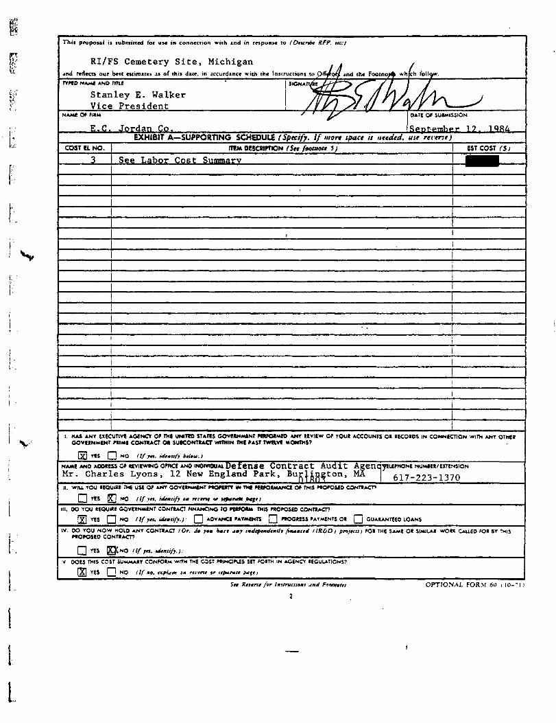
This proposal ii submitted for us* in connection wuh ind in response to f Otttrtbt RFP. tie:)
RI/FS Cemetery Site, Michigan . ,and redects our best estimate* is of this date, in accordance with the Instructions to ptfyroT/f *nd the Footnot^ whph lolly
TYPCD NAME AND rm.E • siGNAii/feV^r""^ /**"// J JStanley E. Walker TfT f "^CJ // y\ / /lAs>> lVice President ///'? S/ {/ ' f*/r ^\ '
NAME Of FIRM ' ' fi/' OATE OF SU»MISSION
E.G. Jordan Co. Sepfember 1?, 1 QRAEXHIBIT A— SUPPORTING SCHEDULE (Specify. If mart space is nttdtd, use ret-erst)
COST El NO.
3
ITEM oesCRtPnON (Sit faotmHt t) EST COST (Si
See Labor Cost SiijrnngrY
!i
1
. ^ i
i
I 1
1
i
i1. HAS ANY EXECUTIVE AGENCY OF THE UNITED STATES GOvfgNMtNT PWO*MK> ANY tEviEW OF YOU* ACCOUNTS O* UCOIOS IN CONNECTION wim ANY OTHEt
GOVEKNMf NT PtIMi CONTIACT Ot SUKONTIACT WTTMIN THE PAST TWaVC MONTHS?
5[] YK fl NO (If jn. ubmufj lalta.:)
NAME AND M»«SS OF «£VIF*ING oFnct AND INOIVTOUAI Defense Contract Audit AgencmuF*ONE NUMIEK/EXTENSIONMr. Charles Lyons, 12 New England Park, Burlington, MA 617-223-1370II. WIU YOU IgQUIXE THE USE OF ANY GOVEINMtNT PIQKITY IM TMt FttFORMANCI OF THIS PROPOSED CONTSACP
Q YES ^] NO (If in, idmiify tn nnnt *r ufenat f*fU
ill. OO YOU IEOUME OOvEINMfNT CONTIAO FINANCING TO PWOtt* THIS PROPOSED CONTIACT?
(Xl YES [~1 "O nf jn. ultmiify.): [~~I ADVANCE PAYMENTS !~1 P«OG»ESS PAYMENTS O« f~l GUARANTEED lOANS
IV. DO YOU NOW MOID ANY CONTRACT (Or. 4a yam h*rt Mf indtftmdtmlh fi**mc,4 llR&Dj pnjKls) FOR THE SAME OR SIMILAR WORK CAUED FOR »Y THISP«OPOSEO CONTRACT?
Q YES 0CNO (If yn. ultmtifj.).
V DOES THIS COST SUMMARY CONFORM WITH THE COST PWNdPUS SET FORTH IN AG£NO REGULATIONS?
[Xi YES | j NO (If mo. t\pittm 3H rtrent 9r ttpara/t flufti
5fr Ktrtr?t ftr Instruction! jn OPTIONAJ. FORM 60 l 10-'I )
L

INSTRUCTIONS TO OFF5RORS
1. The purpose of this form is to provide i >tandard format by whichrhe ofFeror submits to the Government t summary of incurred andestimated costs (and attacked lupptrtmf infirmatiom ) suitable for de*(ailed review ind analysis. Prior co the i<"ird of a contract resultingtram this proposal the orTeror shall, under the conditions Hated mFPR 1-J.307-) be required to submit a Certificate of Current Cast orPricing DIM (See FPR l-j.l07-)(h> and l-i.W-4).
2. to addition co the specific information required by this form, theorTeror it expected, in food fxith. to incorporate in aad submit wicfathis form any additional data, supporting schedules, or substantiationwhich art reasonably required for the conduct of an appropriate re-view and analysis in the light of the specific tacts of this procurement.For effective negotiations, ii i> essential that (here be a clear under-sanding of:
a. The eiisting, verifiable data.b. The judgmental factors applied in projecting from known data
ta the estimate, andc. The contingencies used by the olferor in his proposed price.
In short. th« offerer'» estimating process itself needs to be disclosed.
}. When attachment of suppurting cost or pricing dau to chis form i»impracticable, the data will be described t iritm iciitduiti ji jppnprutti.and made available to the contracting Officer or his represenuti* e uponrequest.
4. The formats for the "Cost Element*" and che "Proposed ContractEstimate ' are not intended u rifid requirements. These may be pre-sented in different formal with the prior approval of the ContractingOfficer if required for more effective and eAcient presentation, tn ailother respects this form will be completed and submitted withoutchange.
i. 3y submission of this proposal the offeror grants to the ContractingOfficer, or his authorized representative, (he right to examine, for thepurpose of verifying the cost or pricing data submitted, thus* booiu,records, documents and other supporting dau which will permit ade-quate evaluation of such cost or pricing data, along with the computa-tions and protections used therein. This right may be exercised in con-nection with any negotiations prior to contract award.
FOOTNOTES
inn celumm thoM mteauiry and rtatammoit fottt irhicb i* tatjudfmtmt of iht o.fmr irM pnporly Ht imtumd in tat tifieitut ptrformamttif tat amtratt. '.rhtm 4*) of ii>t teat im ton etlMimm aart alrtady bttmummd f i . f . . am * IttHr sntratl o.r iJtamyi orottr). dtitnct latmt om amanatatd utpaartimj tentdxit. Idtnttfy ail ultt jmd tnuaftn htitrnm fourflamtt. dirititmt, tr »rfamiznliom> undir t tommom (tmtnl. iraica trt in-dmdtit ill tljMr /*•"« in* lau.tr if ;ttl lo <»• inf»M/ tmmftmr ir curml•uirmtt pmt.
tpftt m idititto* M t*«t jraiioUt im E.\oiitf A it i*fMrW. jl-tfti >tp*r*tt ffgn ut ttttuart *mtt i^etdfy at t6ii "Rtfm*ti" caimanttf Mtottbmtmi in waita tut /•/•"••*"•» lupportimf UM iprtific :»n titmtm*wv 09 fottmd. \'e iimndard format it pwfrieta': «eir'f*^. tbt .'0s/ ir frtt.imf datm mutt it acsartu. ;tmpUM *n* lurrtnl. J«rf (** -udfnimt faetonuud im fn/ntiiif fnm tb* Jala i» ttit ntimutti mull 9* tuitd m lumciiHlJttaii It iHvili lit Ctmiratumf Qffitir it iratvett ta» pripntl. Fir e\-amflt. fnrtdt titt !>*ia uifd for fntimf nuftntlt tmta tt *» etxdor juo-ifaomi. iltof ittimtani. tr imntct fnta; imt r*it»m far iitt of ortrmtaj rautvfita **fari iifrtifltjmth fnm ixptrtomtd rmMt trtotuttj ntmmt. af Lin Hid ma/or n.arramfmtfmi. ae.Ji *r jmitifitaiimm for am imtnuH imla oar ram (ammiaatid if* ft and uiiar? imerraitt. at.). Idntiff juj cs.fiaim jmj cimlimfiman u-«/r* jrt imdtidtd im tat pnpotid fncf. uita atamiicigaltd salt of njttit amat difntiri work, or tmlicipvttd tteamitalditficultitt. '
J tfdicull 16* rant and and1 pmridt am apanpriou txpiamiirit*. 'fhtnafrtumtml hot «f«r rtototd \ritf Gorirmmtmt riprtumitiufa im tin nu offorward prifimf ram. desertnt tat naturt tf tot jfrtttmtmt. Pmrtdt intmtiaad of iotmpiilatiom amti app4ic*ttam' of nur ortrrttod txatint. mctHdiiigcott artakdowm amd laaurtitf trtmdt and. b*d%itarj dtttti at terrxwnr tofrmrtdt a oatit for irobuttam of to* rtatamualtmtu tf frtpattd rain.
4 If tot tout (Oil nttrtd ntrt it im txctu of SliO. pracidt om a upaniltpaft lot follotfimj imfarmiiuam om- taeo uparait mm if ny*ln or lictmitfns mamt and adJmt of tietmur; dau of Itttmu agrttaHM; 3attmt HUM-*rn. fau*l atflitauam itrui immmn. tr oiotr iota om wmtta tin mialt-iit pajaalt: fntf aturtptiam. imtludimj ami part ir madtl tmatoxn of ,atlicomtraet turn or ;oimaomtmt om i-aica i»i rotatly it pajiaali: ptnimiaft ordollar ran of royalty ptr umti; amn priti of somiraet ittut: nuoiotr ofumitt: aid total dollar amamml of nyaltin. In additiom. if iptciftc^ilt rr-1»*iu* »y tot eomtractimf olfcir. a >vfr if tat tarrtmt Hermit afrrtmextand idtmttpcatiam of afpiitaalt iLiimt if iptei/ie fanmti tooU ft pnndtd.
t fnridt j list ofprimupul ittmi u-itaim iota ;aiijftj aidiaaitj tmoiraof amtkipattd tourer, aiuimtuy. umit pmt. competition tfiamtd. amd oatitof' titaatiuiimf tomrct amd rtotomualtmttt of fott.
twttrr *_iup»oRnNC scmouu »NO 'imtt ro OUESTIONS <i ANO v.
OPTIONAL FOR-M (I0-' l)

CONTRACT PRICING PROPOSAL Office of M.n.sem.nt and Budget 1'RESEARCH .I.VO DEl'ELOPMEST) Approvil No. 29-ROI84
PACE NO 1 NO OF PACESThis fora is tat u>e vhea fit submission or <o*t or pricing data (see FPR l-J.8O'«»t is required <nd • -•• ' 1
'i'l tutmituooa for the Optional Form W is tut homed by the contracting oifirtr. J
NAME OF OFFEROR • SUP
Keck Consulting Services , • Inc .HOME OFFICE AOOKSS
1099 West Grand River AvenueWilliamston, Michigan 48895
DtVWIOmS! AHO lOCAltONtSl WBEU WOK U tO M PUfOtMfD TOT
Above
HIES AMD /OR SERVidS IO U FURNISHED
RI - PrimaryCemetary SiteRose Tov*nshipOakland County, MichiganML AMOUNt OF PtOMSAl OOVT SOOOlAnON NO.
DETAIL DESCRIPTION OF COST ELEMENTS
1. OMECT MAIHJAl / lumru, «• CiMcr A)
A PURCHASED PARTS -.*. SUKOHnuCTED ITEMS
TOTAL SEFER-tSI COST f Sj I$T COST- SNds .
" -!*- "-t---V^ -
e. OTHER— 1 1 1 RAW MATEBAl j -- ,--. -•-
(It YOUR StANOARO COMMERCIAL ITEMS 1
(II INTERDIVISiONAl TRANSFERS t At *iutr :ha*m .o/J | i "
TOTAL DIRECT \tATERlAl. ! 1
I. MATERIAL OVERHfAO' tRatt VVJ '*«•=!
i.N.nuM.f^v. ™
Pa1"rick T.vnr'h P-? Rary Rysn ^-9 Robert Minning P-4
I
T07 It D/*£CT i_<80R j
1
MATIO «ATE/ ! 1ST | . •'.-;•- :•'.3URS HOU8 | COST (S) }
i
' i i
i i ? ': i •
-- I" 1 i4. iA(CR OvEtifAS iSptn't OifatMiti or Coil t.t*ttri' ; On RATE , I E»Sl = E S ' C O S T ' i i '• |
.
TOTit LABOR Ol'fKHEAO
Drilling & Related ServicesOsaohvsical ^estina
(see Attachment A) Tor *L Sf
4 SPECJAl ICUiP~{Nl !lf Jirtei -twrr; ilumui tm E.\»i»it t> ( t-f^ft Aht-flr-7 IRAVU (If jinsi .itarjti 'Gilt etuu'i H atmlut' S\ata*ll>
a. TRANSPOIlATiCm
o. PER OlEM OR SbtSlSTENCE
=; ! |
' ' 1
i 1969.00 .EST COST H, , )
i iECIAL T£STI\C ! ,
hmAnf A) • £ S T C O S T < » > :
!
IQTiL TR <••£/. i 1
1. CONSULTANTS (IdiKliff-pmrftu-fjii) f ST COST • J l •i
f ii !i
ror<t COMl'LTlS'T5 : ;
• OtMER 0<RECI COS7S llitmut om £\o./n/ A)
10 rorit DIRE CT COST A \D <jl'£RH£ \O
I I . GENIRAIA.NO »0««NiSTIAIM EiPfNSE ,Rw« 158. 5^ '/••"«'•"•«' ^«- 3&4 f
13. ROT Aims*
11.
14 FEECRPROm 15% Of 1.2 & 11
TOTAL EsriHATto cosr
' U TOTAL ESTIM \TID COST < N O fit OR PKUfIT
OPTIONAL FORMOcaXKT 19*1O*n<ral SCTVKCFPR i - l

FPR 1-16.KU6KMO-IOI
This proposal is submitted (at use in connection with »nd in response to (Otxntt KfP. «*.>
ttA reflects our best estimate! u of this date, in accordance with the Instructions to Offerer* ind the Footnotes which fellow.
TYPED NAME AND (IIU
Robert C. Minning, President
Keck Consulting Services, Inc. SeptentfegJ.1, 1984EXHIBIT A-SUPPORTING SCHEDULE (Specify. I/mon ipaet is ntidtd. uu reient)
COST UNO. ( ITEM DESCRIPTION (Sn feotnoli )j EST COST (S)
i. MAS ANY EIKUTIVE AGENCY OF THE l/NltEO STATES GOVIRN«EN! PfWORMES »NY REVIEW O* YOOR ACC=UMS CR RECSROS .N CSK-ECTIO- wTM ANY OThf*COVERNMlNI PRIME CONTRAa OR JU»CO*TR*CT WITHIN THE P«SI TWEIVE MO.WS?
YtS Q NO flfftl. idtmnfj Mou.)NAME AND AOORESS Of REVIEWING OTNCI ANO INCXV1CHJA1
i. wu YOU REOUIRE ix use or AN» OOVERNMENI PROPUTY M THE PERFORMANCE OF rms ptoposia ccNr**^1
Q ns Q NO I If yn. idtmitfi om nnnt or *fa,au fajHHI. CO YOU RtOulM GOVERNMENT CONTRACT FMAMdNG TO PtVORM THIS PROPOSED CONTRACT?
Q n$ ([3 NO fl/fti.ldtmiift.1: Q AOVANO PAYMENTS Q PROGRESS P»Y-«NTS OR GUARANTEED LOANS
W. 00 YOU NOW xoi.0 ANY CONTRACT (Or. do ;e« *Jr« am, imd,ttmdt,d, fi~m<,J HRC-D)WOPOSEO CONltACT?
»OR THE SAME OR SI»IA» wC« CXiE3 KJR IY THIS
nS NO I If jm. id
V. DOES TMS COSI SUMMARY CONFORM WITH THE COST PRINOPUS SO FORTH IN AGENCY REGiAATIONS?
f) YtS []j NO I If «•. *\plam om mint or itfaratt p~(t)
in Rtrtnt for Imunnl
2
OPTIONAL fORM 60 UO-'l)
L

CONTRACT PRICING PROPOSAL'RESEARCH I.SD DEI'£tO*>.\IE.\7V
Office of Management and BudgetApproval No. 29-ROI84
This form is Bsr «<e vheo lit submiuioa or co«t or pcione. d>a torn* FPR. l-}.«O^-»» is required jnd'«J sutniininoo for the Option*! Form *9 u sutbomed br the conmctin| officer.
PACE NO. NO. Of PACES
NAME OP OFFEROR
Keck Consulting Services. 'Inc.HOME OFFICE AOORESS
1099 West Grand River AvenueWilliamston, Michigan 48895
SUPPUES AND/OR URViCES TO M
RI - SecondaryCenetary SiteRose TownshipOakland County, Michigan
WORK is 10 u PEVORMEO tOTAl AMOUNI O* MOPOlAl
, 13,172.00GCvt SOUOlADON NO.
DETAIL DESCRIPTION OF COST ELEMENTS
I. DEUCT MAfERiAi ilumnt oa £**«*« At esi cost TOTAlf SI COST'
REFER-
a. PURCHASES PARTS
*. SUlCONItACTEO ITEMS
e. OrntR—/ / ) RAW
I)) YOUR STANDARD COMMERCIAL ITEMS
lit INTER9IV1SIONA1 TRANSFERS I At tlatr it**
TOTAL DIRECT UATERlAL
1 MATERIM OVERHEAD' / Rail
j. OIRECT UIOR <S?,.ifl>ESTIMATED
HOURSRATE/HOUR
ESTCOST 15)
Patrick Lynch 1? 2Gary Ryan T-2
T07.1t DIRECT H60R
4. IA«CR Ovt«>-.tAS l i f t o f f Diparlmnt or CM o.n. RATE i IASE = ESICCS:
TOT.it C-tflOR WEKHCAD ii. IPlCiAl T|;r.^C l l*ii*at«f fltlj u«r* at Crortrwmtml imllaliali»*l I EStCSST t ,
Drillina & Related Services(see Attachment A)
TOTU SPECIAL. SPECUt (If dirtcl fbart.il llumutom A1
7 TRAVEL . If a'trtit .Awrjt, (Cut dttaijl om alHtftd EST COST .'f /
a. TRANSPORTATION
t. PER CIE« CR70T1L
CONSULTANTS t —pareou—rattl ES7COSI < S »
TOT it CONJltTlVTi
. OTHER CKtCT COSTS Ilifnti oa E.\atan AI
0. TO J i t DIRECT COST A\D 'JlfRHEAO
1 CESERAl A.NO ADMINISTRATIVE EIKNSC /«•'« 158 . 5% 1 ••" '''-'•' N'«* 3&4
J. ROYAtTJES •
TOT It ESTIVATtD COST,
4 FEECRPR01T 1D% O£ 1, / & 11
TOTlL CSTUt -iTfD COJT I NO Fie. <i* PROFIT
I OPTIONAL FORM 6OOcrcoer IVI
MVCS A-minajrjiK

FPS. i-lb»UOXV6»-IOI
Thu propoul is submitted foe use in connection with »nd in teipuase to (Otxntt RFP. at. I
and reflects our best estimates as ol" this dau. in accordance with the Instruct wo j to Oderon jnd rhe footnotes which tallow.TVPCONAMt ANO TRIE
Robert C. Minning, PresidentNAME OPP1RM
Keck Consulting Services, Inc. 1984EXHIBIT A-SUPPORTING SCHEDULE (Specify. If more tpatt if Httdtd. ute rrtentj
COST El NO. ITEM DESCRIPTION (Stt footnott tt \ EST COST <S)
JL
I. HAS ANY UKUT1VE AGENCY Of IXE UNITED STATES GOVERNMENT PERFORMED ANY (EVIt>v Ol YOot »CCC^N'S CiGOVERNMENT PRIME CONrtACT OR SUE-CONTRACT WITHIN THE PAST TWRVE MONTHS?
vtl Q NO (l/ftt. lattmufy \tlov.)
NAME ANO AOOttU Or REVIEWSNG OFFICE AMO INCMVltXJAl
II. wu YOU RtQUKE THE USE OP ANT GOVERNMENT PROPERTY M THE PERFORMANCE OF THIS PRCPOSE3 CC*>rtAC^
II YES ( | NO (If yn. tdtmltft om rtnnt or *pmrau pa f t )
W. DO YOU REQUIRE GOVERNMENT CONTRACT MNAMONG TO PWORM tMtS PROPOSES CCNTRACT>
Q TIS O NO ll/ftt. idtmtif,.).- Q AOVAMO PAYMENT* Q PRCG»ESS F»Yfcf<n OR
IV. OO YOU NOW HOLD ANY CONTRACT I Or. da yoa tan amf imdiftudtmllj Ji^amilJ flR&Dl fngt.ni *OR ><E SAME O* SMilAl w>CtX CXiH) FO* |Y THISPROPOSED
YES Q NO llf Jtl. -dtmtif,..
V. DOtS THIS COST SUMMARY CONFORM WITH THE COST FRlNQPUS SET FORTH IN AGENCY
f~) VES (~1 MO I If a*. <\fl*i* om nitru or lifaratf faff t
Saf Rtnrtt for tmlfr*ffmml jmd
2
OPTIONAL FORM 60 i lO-'U

Attachment A
Cost Estimate - Primary DrillingCemetary Site
1. Drilling - Hollow stem auger with split spoon samplesat 10-foot intervals and/or change in formation throughoutunsaturated zone (static water level estimated at 30 feetBGL) and screened auger samples at 10-foot intervalsstarting at 40 feet BGL to total depth.
a. Drilling - 4 boreholes to 120 feet and 1borehole to 60 feet BGL
1. 460 feet at less than 100 feet@ $7.00/ft. $ 3,220.00
2. 80 feet at greater than 100 feet@ $9.00/ft. 720.00
b. Split Spoon Sampling
1. 4 boreholes with 4 samples/borehole16 samples @ $20.00/sample 320.00
2. 1 borehole with 4 samples4 samples @ §20.OO/sample 80.00
c. Screened Auger Samples
1. 4 boreholes with 8 samples/borehole32 samples @ $50.00/sample 1,600.00
2. 1 borehole with 3 samples/borehole3 samples @ $50.00/sample 150.00
Subtotal: $ 6,090.00
2. Monitor Wells - 4 clusters with screens set at60 feet and 120 feet BGL and 1 single well withscreen set at 60 feet BGL.
a. Well Screens - 5-foot stainless steel9 screens @ $193.00/screen 1,741.50
b. Casing - 2-inch galvanized823 feet @ $3.00/ft. 2,469.00
c. Well Guards5 guards @ $150.00/guard 750.00
»d. Sand Pack
9 wells @ $40.00/well 360.00
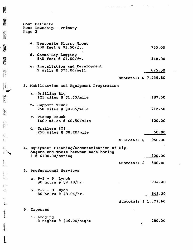
fl Cost EstimateRose Township - Primary
pr Page 2
e. Bentonite Slurry GroutI 500 feet @ $1.50/ft. 750.00
f. Gamma-Ray Loggingg 540 feet % Sl.OO/ft. 540.00
g. Installation and DevelopmentII 9 wells @ §75.00/well 675.00
Subtotal: $ 7,285.50*
T'rji 3. Mobilization and Equipment PreparationW"
a. Drilling Rig§ 125 miles @ $1.50/mile 187.50l%i
b. Support Truck& 250 miles @ $0.85/mile 212.50
c. Pickup Truckr 1000 miles @ §0.50/mile 500.00
P' d. Trailers (2)
250 miles @ $0.20/mile 50.00
I Subtotal: $ 950.00
| 4. Equipment Cleaning/Decontamination of Rig,i X Augers and Tools between each boring
5 @ $100.00/boring 500.00
1-- Subtotal: $ 500.00i.
5. Professional Services
- a. P-2 - P. Lynch80 hours @ ?9.18/hr. 734.40
{ b. T-2 - G. Ryan80 hours @ ?8.04/hr. 643.20
j Subtotal: $ 1,377.60
6. Expenses
I
t
a. Lodging8 nights @ $35.00/night 280.00

Cost EstimateRose Township - PrimaryPage 3
b. Per Diem10 days @ $60.00/day
c. Hotwater/High Pressure Washer10 days @ $50.00/day
d. Air Compressor10 days @ §60.00/day
7. Geophysical Testing
a. Electrical Resistivity3 days @ $600.00/day
b. Ground Pentrating Radar2 days @ $l,900.00/day
8. BacXhoe and Operator5 days @ ?900.00/day
600.00
500.00
600.00
Subtotal: § 1,980.00
1,800.00
3,800.00
Subtotal: $ 5,600.00
4,500.00
Subtotal: $ 4,500.00
TOTAL COST ESTIMATE: $28,282.50*
*plus overhead, G & A and profit
I
I

Attachment A
Cost Estimate - Secondary DrillingCemetary Site
1. Drilling - Hollow stem auger with split spoon samplesat 10-foot intervals and/or change in formation throughoutunsaturated zone (static water level estimated at 30 feetBGL) and screened auger samples at 10-foot intervalsstarting at 40 feet BGL to total depth.
a. Drilling - 3 boreholes to 120 feet
1. 300 feet at less than 100 feet@ $7.00/ft. ' $ 2,100.00
2. 60 feet at greater than 100 feet@ $9.00/ft. 540.00
b. Split Spoon Sampling
1. 3 boreholes with 4 samples/borehole12 samples @ $2O.OO/sample 240.00
c. Screened Auger Samples
1. 3 boreholes with 8 samples/borehole24 samples @ $50.00/sample 1,200.00
Subtotal: $ 4,080.00
2. Monitor Wells - 3 clusters with screens setat 60 feet and 120 feet BGL.
a. Well Screens - 5-foot stainless steel6 screens @ ?193.00/screen 1,161.00
b. Casing - 2-inch galvanized522 feet @ ?3.00/ft. 1,566.00
c. Well Guards3 guards @ $150.00/guard 450.00
d. Sand Pack6 wells 8 $40.00/welll 240.00
e. Bentonite Slurry Grout330 feet @ $1.50/ft. 445.00
f. Gamma-Ray Logging360 feet @ §1.00/ft. . 360.00
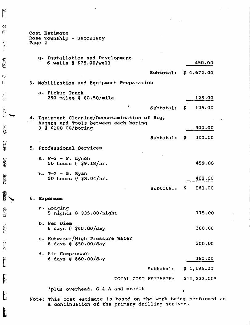
Cost EstimateRose Township - SecondaryPage 2
g. Installation and Development6 wells @ ?75.00/well 450.00
Subtotal: $ 4,672.00
3. Mobilization and Equipment Preparation
a. Pickup Truck250 miles @ $0.50/mile 125.00
Subtotal: ? 125.00
4. Equipment Cleaning/Decontamination of Rig,Augers and Tools between each boring3 @ $100.00/boring 300.00
Subtotal: $ 300.00
5. Professional Services
a. P-2 - P. Lynch50 hours @ $9;18/hr.
b. T-2 - G. Ryan50 hours @ $8.04/hr.
6. Expenses
a. Lodging5 nights @ $35.00/night
b. Per Diem6 days @ $60.00/day
c. Hotwater/High Pressure Water6 days @ $50.00/day
d. Air Compressor6 days @ $60.00/day
Subtotal:
459.00
402.00
861.00
175.00
360.00
300.00
360.00
Subtotal: $ 1,195.00
TOTAL COST ESTIMATE: $11,233.00*
*plus overhead, G & A and profit }
Note: This cost estimate is based on the work being performed asa continuation of the primary drilling serivce.

APPENDIX A
LL
It

I
MATTHEW D. JERUE, CHEMICAL/ENVIRONMENTAL ENGINEER
Education
University of Michigan - B.S. in Chemical Engineering, 1976- B.S. in Environmental Engineering, 1976
Professional Experience
Mr. Jerue is experienced in the conduct of hazardous waste management studies(prospective and retrospective), including those of an industrywide nature.
He has performed hazardous waste management inspections and audits to assesspotential liabilities, and made recommendations for waste management and/orremedial activities programs at a variety of industrial facilities and land-fills. He has performed evaluations of'unit operations to assess their poten-tial to produce hazardous waste, as well as determinations of potential hazar-dous wastes generated during various demolition projects.
Mr. Jerue has prepared health and safety procedure manuals for onsite inspec-tions and drilling operations, and technical feasibility and economic impactdata for proposed governmental regulations. He is thoroughly familiar with EPAand DOT hazardous materials regulations and has participated in hazardousmanagement and DOT hazardous material (regulations) orientation and trainingseminars for both clients and parent company personnel and clients.
Since coming to the E.C. Jordan Co., Mr. Jerue has been involved in fieldactivities including sample collection and field analysis. He is experiencedin the operation of field analytical equipment such as the Photovac 10A10organic vapor analyzer.
JERUE,MATTHEW/10001.0.0
ECJORDANCQ

MICHAEL O'HEARN, HYDROLOGIST
Education
Humboldt State University - B.S. in Environmental Engineering, 1979
Professional License
Engineer-in-Tra ining
Affiliations
National Water Well Association, Technology DivisionIllinois Groundwater Association
Professional Experience ' >
Mr. O'Hearn is responsible for hydrological investigations of a variety ofhazardous waste investigations.
Mr. O'Hearn was Associate Hydrologist for the Illinois State Water Survey wherehe was responsible for research on groundwater quality and contamination. Hedesigned an ambient groundwater quality monitoring program for Illinois and was
I p a major contributor to the design and construction of a non-contaminating,1 '"j submersible pump to collect groundwater samples from monitoring wells.
|i [ , Mr. O'Hearn served on a technical advisory committee to the Illinois EPAconcerning groundwater management. He contributed to the development ofregulations for the design and operation of waste management facilities andevaluated proposed waste management sites for potential impacts on groundwaterresources.
Partial List of Publications
"Groundwater Monitoring at the Woodriver Power Station's Ash DisposalPonds," by M. W. Hampton and M. O'Hearn, limited distribution con-tract report, Illinois State Water Survey, Champaign, Illinois.November 1983.
"A Summary of Information Related to the Comprehensive Management ofGroundwater and Surface Water Resources in the Sangamon River Basin,Illinois," by M. O'Hearn and T. L. Williams, Contract Report 299,Illinois State Water Survey, Champaign, Illinois. November 1982.
I I
I
1
O'HEARN,MICHAEL/10 0 0 1-Q-° ECJORDANCQ

MICHAEL O'HEARN (Continued)
"Illinois Groundwater Monitoring Network—A Planning Document for NetworkDesign," by L. R. Frost, Jr., M. O'Hearn, J. P. Gibb, and M. G.Sherrill, U.S. Geological Survey Open-File Report (in press),Champaign, Illinois. January 1982.
"Surface Water - Groundwater Quality Relationships for a Central IllinoisWatershed," by J. P. Gibb and M. O'Hearn, Contract Report 248,Illinois State Water Survey, Champaign, Illinois. January 1981.
I:
L
LO'HEARN,MICHAEL/10002-Q-° __ ECJORDANCQ

Resume of
IIPersonal
Education
ProfessionalExperience
1981 - Present
Summer, 1981
LL
1975 - 1978
Special Interestsand Hobbies
Patrick M. Lynch
Kalamazoo, Michigan
Birthdate:
49002
Kalamazoo, MichiganHeight: "Weight: Ibs.Health: ExcellentMarital Status:
Western Michigan UniversityKalamazoo, MichiganB.S. in Geology, June, 1981
Keck Consulting Services, Inc.Williamston, Michigan—Field GeologistFieldwork includes: soils classi-fication, surveying, mapping,direction of drilling test boringsand installation of wells for hydro-geologic investigations, aquifertesting, earth resistivity testingand borehole geophysical logging.Office work includes: datacontouring, general drafting, dataanalyses and resistivity data ana-lyses .
Core LaboratoriesMt. Pleasant, Michigan—Core AnalyistAnalysis of rock samples to deter-mine porosity, permeability andresidual fluid saturations.
Bud Mein Builders—Performed block, brick and stonemasonry work.
Music (clarinet), art (pastels),woodworking, antique furniture andauto restoration, bass & troutfishing.
I

I IP|vf.
I • .
iiv
LABOR COST SUMMARY
LI

ROSETOWNSHIPCEMETERY
I "LEGEND
APPROXIMATE AREA OFBURIED DRUMS
DOMESTIC WELL
EXISTING MONITORING WELL
PROPOSED MONITORING WELL
I
I
I
H 200 UOOFEET
FIGURE 2-3PROPOSED LOCATIONS OF MONITORING WELLS
CEMETERY SITEMICHIGAN DEPARTMENT
OF NATURAL RESOURCES
ECJORDANCQ