REMEDIAL ACTION PLAN SAN DIEGO SHIPYARD SEDIMENT SITE · REMEDIAL ACTION PLAN SAN DIEGO SHIPYARD...
231
REMEDIAL ACTION PLAN SAN DIEGO SHIPYARD SEDIMENT SITE Cleanup and Abatement Order No. R9‐2012‐0024 Prepared by Anchor QEA, L.P. 26300 La Alameda, Suite 240 Mission Viejo, California 92691 June 12, 2012
Transcript of REMEDIAL ACTION PLAN SAN DIEGO SHIPYARD SEDIMENT SITE · REMEDIAL ACTION PLAN SAN DIEGO SHIPYARD...
REMEDIAL ACTION PLAN
SAN DIEGO SHIPYARD SEDIMENT SITE
Cleanup and Abatement Order No. R9‐2012‐0024
Prepared by
Anchor QEA, L.P.
26300 La Alameda, Suite 240
Mission Viejo, California 92691
June 12, 2012
Remedial Action Plan June 2012 San Diego Shipyard Sediment Site i
TABLE OF CONTENTS
1 INTRODUCTION .................................................................................................................. 1
1.1 Structure of this Document .............................................................................................1
1.1.1 Design Criteria Report ...............................................................................................2
1.1.2 Quality Assurance Project Plan .................................................................................2
1.1.3 Remediation Monitoring Plan ...................................................................................2
1.1.4 Sampling and Analysis Plan .......................................................................................2
1.1.5 Community Relations Plan ........................................................................................2
1.1.6 Health and Safety Plan ...............................................................................................4
1.2 Summary of RAP Elements Required by CAO ..............................................................4
1.3 Duty to Use Registered Professional ...............................................................................5
2 SELECTED REMEDY ............................................................................................................ 6
2.1 Cleanup Objectives and Cleanup Levels .........................................................................6
2.2 Remedial Footprint ..........................................................................................................6
2.3 Corrective Actions ...........................................................................................................7
3 PROJECT TEAM AND ORGANIZATION ......................................................................... 12
4 IMPLEMENTATION PLAN FOR REMEDIAL ACTION ................................................... 14
4.1 Design Activities and Site Studies .................................................................................14
4.2 Apply for and Obtain Project Permits ..........................................................................14
4.3 Coordination with the Public ........................................................................................14
4.4 Prepare Contract Documents ........................................................................................14
4.5 Award Contract ..............................................................................................................15
4.6 Oversee and Monitor Construction ..............................................................................15
4.7 Final Cleanup and Abatement Completion Report ......................................................15
4.8 Post-Remedial Monitoring Plan ....................................................................................15
5 REGULATORY PERMITS AND APPROVALS .................................................................. 16
5.1 California Environmental Quality Act .........................................................................16
5.2 Rivers and Harbors Act Section 10 and Clean Water Act Section 404 Permits .........16
5.3 Endangered Species Act/Magnusson-Stevens Fishery Conservation and Management
Act ...................................................................................................................................16
5.4 Section 401 Water Quality Certification and Waste Discharge Requirements ..........17
5.5 California Coastal Act Consistency ...............................................................................17
Table of Contents
Remedial Action Plan June 2012 San Diego Shipyard Sediment Site ii
5.6 Other Reports and Entitlements ...................................................................................17
6 REMEDIATION SCHEDULE .............................................................................................. 18
7 REFERENCES ...................................................................................................................... 20
List of Tables
Table 1 Elements Required by the CAO ............................................................................ 4
Table 2 Sediment Concentration Goals Mandated by CAO ............................................. 6
List of Figures
Figure 1 Site Map .................................................................................................................. 3
Figure 2 Thiessen Polygon Distribution and Required Cleanup Areas ............................. 9
Figure 3 Remedial Footprint within North Shipyard Area .............................................. 10
Figure 4 Remedial Footprint within South Shipyard Area .............................................. 11
Figure 5 Project Team Organizational Chart .................................................................... 13
Figure 6 Remediation Schedule ......................................................................................... 19
List of Appendices
Appendix A Design Criteria Report
Appendix B Quality Assurance Project Plan
Appendix C Remedial Monitoring Plan
Appendix D Sampling and Analysis Plan
Appendix E Community Relations Plan
Appendix F Health and Safety Plan
Remedial Action Plan June 2012 San Diego Shipyard Sediment Site iii
LIST OF ACRONYMS AND ABBREVIATIONS
μg microgram
BAE System BAE Systems San Diego Ship Repair Facility
CAO Cleanup and Abatement Order
CCA California Coastal Act
City City of San Diego
COC contaminant of concern
CRP Community Relations Plan
CWA Clean Water Act
DCR Design Criteria Report
EIR Environmental Impact Report
EFH Essential Fish Habitat
ESA Endangered Species Act
HASP Health and Safety Plan
HPAH high molecular weight polycyclic aromatic hydrocarbon
kg kilogram
mg milligram
NASSCO National Steel and Shipbuilding Company Shipyard Facility
NEPA National Environmental Policy Act
QAPP Quality Assurance Project Plan
Port San Diego Unified Port District
PCB polychlorinated biphenyl
RAP Remedial Monitoring Report
RMP Remediation Monitoring Plan
Shipyard Sediment Site San Diego Shipyard Sediment Site
SAP Sampling and Analysis Plan
SWAC surface-weighted average concentrations
TBT tributylin
USACE U.S. Army Corps of Engineers
Water Board San Diego Regional Water Quality Control Board
WDR Waste Discharge Requirements
WQC Water Quality Certification
Remedial Action Plan June 2012 San Diego Shipyard Sediment Site 1
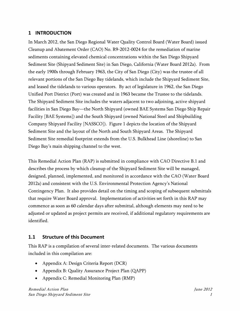
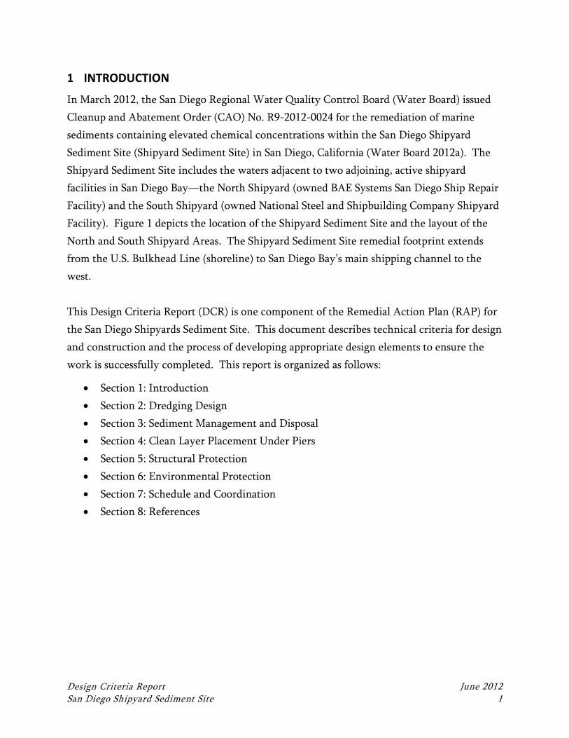
1 INTRODUCTION
In March 2012, the San Diego Regional Water Quality Control Board (Water Board) issued
Cleanup and Abatement Order (CAO) No. R9-2012-0024 for the remediation of marine
sediments containing elevated chemical concentrations within the San Diego Shipyard
Sediment Site (Shipyard Sediment Site) in San Diego, California (Water Board 2012a). From
the early 1900s through February 1963, the City of San Diego (City) was the trustee of all
relevant portions of the San Diego Bay tidelands, which include the Shipyard Sediment Site,
and leased the tidelands to various operators. By act of legislature in 1962, the San Diego
Unified Port District (Port) was created and in 1963 became the Trustee to the tidelands.
The Shipyard Sediment Site includes the waters adjacent to two adjoining, active shipyard
facilities in San Diego Bay—the North Shipyard (owned BAE Systems San Diego Ship Repair
Facility [BAE Systems]) and the South Shipyard (owned National Steel and Shipbuilding
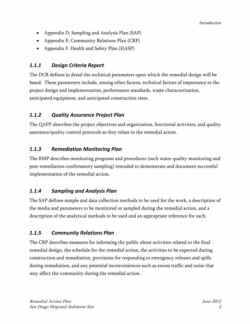
Company Shipyard Facility [NASSCO]). Figure 1 depicts the location of the Shipyard
Sediment Site and the layout of the North and South Shipyard Areas. The Shipyard
Sediment Site remedial footprint extends from the U.S. Bulkhead Line (shoreline) to San
Diego Bay’s main shipping channel to the west.
This Remedial Action Plan (RAP) is submitted in compliance with CAO Directive B.1 and
describes the process by which cleanup of the Shipyard Sediment Site will be managed,
designed, planned, implemented, and monitored in accordance with the CAO (Water Board
2012a) and consistent with the U.S. Environmental Protection Agency’s National
Contingency Plan. It also provides detail on the timing and scoping of subsequent submittals
that require Water Board approval. Implementation of activities set forth in this RAP may
commence as soon as 60 calendar days after submittal, although elements may need to be
adjusted or updated as project permits are received, if additional regulatory requirements are
identified.
1.1 Structure of this Document
This RAP is a compilation of several inter-related documents. The various documents
included in this compilation are:
Appendix A: Design Criteria Report (DCR)
Appendix B: Quality Assurance Project Plan (QAPP)
Appendix C: Remedial Monitoring Plan (RMP)
Introduction
Remedial Action Plan June 2012 San Diego Shipyard Sediment Site 2
Appendix D: Sampling and Analysis Plan (SAP)
Appendix E: Community Relations Plan (CRP)
Appendix F: Health and Safety Plan (HASP)
1.1.1 Design Criteria Report
The DCR defines in detail the technical parameters upon which the remedial design will be
based. These parameters include, among other factors, technical factors of importance to the
project design and implementation, performance standards, waste characterization,
anticipated equipment, and anticipated construction rates.
1.1.2 Quality Assurance Project Plan
The QAPP describes the project objectives and organization, functional activities, and quality
assurance/quality control protocols as they relate to the remedial action.
1.1.3 Remediation Monitoring Plan
The RMP describes monitoring programs and procedures (such water quality monitoring and
post-remediation confirmatory sampling) intended to demonstrate and document successful
implementation of the remedial action.
1.1.4 Sampling and Analysis Plan
The SAP defines sample and data collection methods to be used for the work, a description of
the media and parameters to be monitored or sampled during the remedial action, and a
description of the analytical methods to be used and an appropriate reference for each.
1.1.5 Community Relations Plan
The CRP describes measures for informing the public about activities related to the final
remedial design, the schedule for the remedial action, the activities to be expected during
construction and remediation, provisions for responding to emergency releases and spills
during remediation, and any potential inconveniences such as excess traffic and noise that
may affect the community during the remedial action.
SDG&EParcel
Figure 1Site Map
San Diego Shipyard Sediment Site
Q:\Job
s\0201
96-01
_BAE
_Syste
ms\M
aps\RA
P\Loca
ton_M
ap.mx
d nko
chie 6/
12/201
2 12:
55:14
PM
0 200 400 600 800Feet
[
! ! Shipyard Leasehold LineShipyard Sediment Site
§̈¦5 §̈¦805
§̈¦8§̈¦15
§̈¦15
Pacific OceanPacific Ocean
San Diego Bay
San Diego Bay
Chula Vista
National City
CoronadoBonita
San Diego
Buildin
g Ways
4 Buildin
g Ways
3On B
lock
Building
Dock 1Be
rth W
all
Berth I
Berth
III
Berth
IV
Berth
V
Berth
VI
Berth VII
Berth
IXBerth
X
Pier 3
City Outfall
Pier 2
Pier 1
Extent of Shipyard Sediment Site
ShipyardSediment
Site
NORTHSHIPYARD
AREA(SEE FIGURE 2)
SOUTHSHIPYARD
AREA(SEE FIGURE 3)
North Shipyard Leasehold LineSouth Shipyard Leasehold Line
San DiegoCoronado
National City
Chula Vista
Bonita
Introduction
Remedial Action Plan June 2012 San Diego Shipyard Sediment Site 4
1.1.6 Health and Safety Plan
The HASP describes health and safety measures to be used during the design, construction,
and post-construction monitoring phases of the work, including employee training,
protective equipment, medical surveillance requirements, standard operating procedures, and
contingency plans.
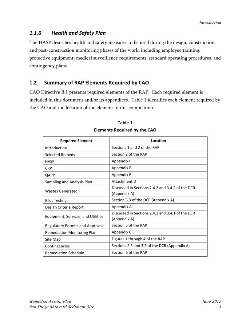
1.2 Summary of RAP Elements Required by CAO
CAO Directive B.1 presents required elements of the RAP. Each required element is
included in this document and/or its appendices. Table 1 identifies each element required by
the CAO and the location of the element in this compilation.
Table 1
Elements Required by the CAO
Required Element Location
Introduction Sections 1 and 2 of the RAP
Selected Remedy Section 2 of the RAP
HASP Appendix F
CRP Appendix E
QAPP Appendix B
Sampling and Analysis Plan Attachment D
Wastes Generated Discussed in Sections 2.4.2 and 3.4.2 of the DCR
(Appendix A)
Pilot Testing Section 3.3 of the DCR (Appendix A)
Design Criteria Report Appendix A
Equipment, Services, and Utilities Discussed in Sections 2.4.1 and 3.4.1 of the DCR
(Appendix A)
Regulatory Permits and Approvals Section 5 of the RAP
Remediation Monitoring Plan Appendix C
Site Map Figures 1 through 4 of the RAP
Contingencies Sections 2.3 and 3.3 of the DCR (Appendix A)
Remediation Schedule Section 6 of the RAP
Remedial Action Plan June 2012 San Diego Shipyard Sediment Site 6
2 SELECTED REMEDY
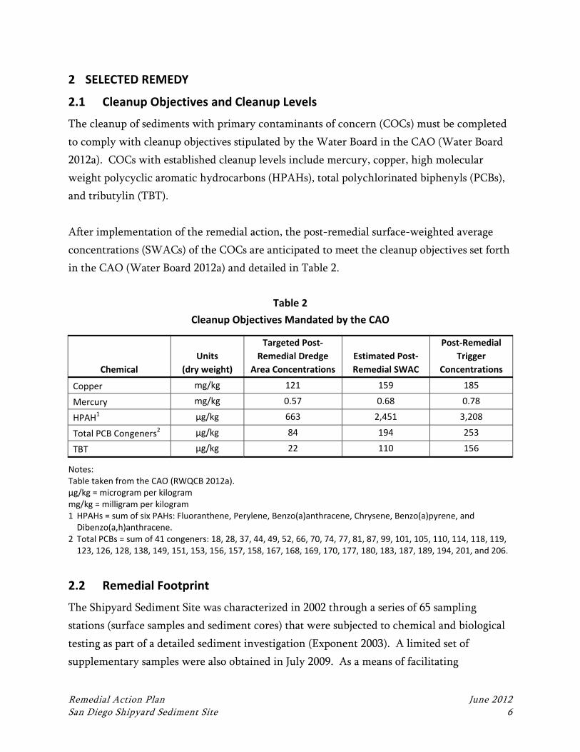
2.1 Cleanup Objectives and Cleanup Levels
The cleanup of sediments with primary contaminants of concern (COCs) must be completed
to comply with cleanup objectives stipulated by the Water Board in the CAO (Water Board
2012a). COCs with established cleanup levels include mercury, copper, high molecular
weight polycyclic aromatic hydrocarbons (HPAHs), total polychlorinated biphenyls (PCBs),
and tributylin (TBT).
After implementation of the remedial action, the post-remedial surface-weighted average
concentrations (SWACs) of the COCs are anticipated to meet the cleanup objectives set forth
in the CAO (Water Board 2012a) and detailed in Table 2.
Table 2
Cleanup Objectives Mandated by the CAO
Chemical
Units
(dry weight)
Targeted Post‐
Remedial Dredge
Area Concentrations
Estimated Post‐
Remedial SWAC
Post‐Remedial
Trigger
Concentrations
Copper mg/kg 121 159 185
Mercury mg/kg 0.57 0.68 0.78
HPAH1 µg/kg 663 2,451 3,208
Total PCB Congeners2 µg/kg 84 194 253
TBT µg/kg 22 110 156
Notes: Table taken from the CAO (RWQCB 2012a). µg/kg = microgram per kilogram mg/kg = milligram per kilogram 1 HPAHs = sum of six PAHs: Fluoranthene, Perylene, Benzo(a)anthracene, Chrysene, Benzo(a)pyrene, and
Dibenzo(a,h)anthracene. 2 Total PCBs = sum of 41 congeners: 18, 28, 37, 44, 49, 52, 66, 70, 74, 77, 81, 87, 99, 101, 105, 110, 114, 118, 119,
123, 126, 128, 138, 149, 151, 153, 156, 157, 158, 167, 168, 169, 170, 177, 180, 183, 187, 189, 194, 201, and 206.
2.2 Remedial Footprint
The Shipyard Sediment Site was characterized in 2002 through a series of 65 sampling
stations (surface samples and sediment cores) that were subjected to chemical and biological
testing as part of a detailed sediment investigation (Exponent 2003). A limited set of
supplementary samples were also obtained in July 2009. As a means of facilitating
Selected Remedy
Remedial Action Plan June 2012 San Diego Shipyard Sediment Site 7
comparative evaluations of feasibility, environmental protectiveness, and cost, the Shipyard
Sediment Site was subdivided into a set of Thiessen polygons (bounded by half the distance
between adjacent sampling stations), each of which is represented by a single sampling
station at or near its mid-point. The distribution and extents of Thiessen polygons at the
Shipyard Sediment Site are depicted on Figure 2.
Based on considerations of chemical and biological exposure and risk detailed in the Water
Board’s Detailed Technical Report (Water Board 2012b), 23 individual sampling stations and
their accompanying Thiessen polygon areas have been targeted for cleanup, with the goal of
achieving the desired SWAC values across the Shipyard Sediment Site (see Table 2). Five
areas are located within the South Shipyard Area, 17 areas are located within the North
Shipyard Area, and one area is shared by both areas. Based on the available data, the
proposed cleanup is intended to meet the cleanup levels for the primary COCs.
The individual cleanup areas were converted from their Thiessen polygon geometry to more
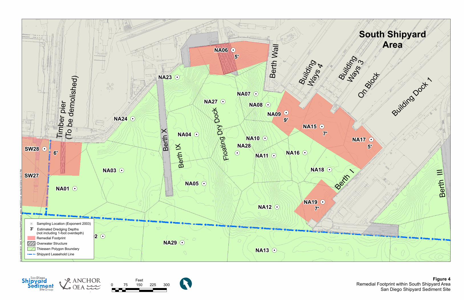
realistic design/construction boundaries within the two Shipyard Areas. Figures 3 and 4
depict the relevant Thiessen polygons and assumed equivalent remedial extents for the North
and South Shipyard Areas, respectively. These figures show the remedial footprint and
include open-water areas in red and underpier areas in green.
2.3 Corrective Actions
Mechanical dredging is the selected remedial action for cleanup of the remedial footprint.
Dredging will be conducted to remove impacted sediments from all accessible portions of the
Shipyard Sediment Site. Dredged material will be offloaded to an onshore stockpiling
location where it will be dewatered, loaded into trucks, and transported to one or more off-
site disposal locations. Mechanical dredging will be supplemented, where necessary, by
localized placement of clean sand cover in cleanup areas (depending on various factors,
including the results of post-remediation confirmatory sampling) as a mechanism for further
enhancing the sediment surface. Cleanup areas below overwater structures will receive a
cover layer of clean sand rather than being dredged, owing to accessibility issues and the
need to maintain stability of the structures.
Selected Remedy
Remedial Action Plan June 2012 San Diego Shipyard Sediment Site 8
The target depth for remediation is the maximum depth of chemical exceedance relative to
CAO target cleanup levels. Based on preliminary calculations, dredging to a point where the
target sediment levels are achieved will result in the removal of approximately 143,400 cubic
yards (cy) of material. Further design-level evaluations (e.g., calculation of structural setback
distances and dredged side slopes) will better refine this estimated dredge volume. All
dredged material will be offloaded to an onshore stockpiling location where it will be
dewatered, loaded into trucks, and transported to one or more off-site disposal locations.
Following sediment removal, the stability of existing marine structures, seawalls, and side
slopes will be maintained, if needed, by placing a ridge or blanket of protective rock material
adjacent to the structure in question, thereby replacing the stabilizing effect of sediment
removal.
!.
!.
!.
!.
!. !.
!.
!.
!.
!.
!.
!.
!.
!.!.
!.
!.
!.
!.
!.
!.
!.
!.
!.
!.
!.
!.
!.
!.
!.
!.
!.
!.
!.
!.
!.
!.
!.
!.
!.
!.
!.
!.
!.
!.
!.
!.!.
!.
!.
!.!.
!.
!.
!.
!.
!.
!.
!.
!.
!.
!.
!.
!.
!.
!.
!.
Floati
ng D
ry Do
ck
SW07
SW06
SW26
SW05 SW14 SW16
SW15
SW22
SW09
SW13
SW18
SW21
SW23
SW11SW03
SW36
SW34
SW31
SW33
SW32
SW30
SW29
SW28
SW25
SW24
SW12
SW08SW04
SW02
SW27
SW20
SW19
SW17
SW10
NA21
NA20
NA19
NA17
NA09
NA16
NA06
NA04
NA23
NA24
NA01
NA13NA29
NA02
NA31
NA25
NA30NA26NA14
NA08
NA10
NA18
NA22
NA19
NA15
NA05
NA07
NA12
NA11
SW01
NA03
NA28
NA27
Figure 2Thiessen Polygon and Required Cleanup Areas
San Diego Shipyard Sediment Site
\\Orca
s\GIS\
Jobs\0
20196
-01_B
AE_Sy
stems
\Maps
\2010
_11\Th
iessen
_Rem
edial_
Footpr
int.m
xd nk
ochie
11/11
/2010
2:46 P
M
0 150 300 450 600Feet
[
!. Sampling Location! ! Shipyard Leasehold Line
Thiessen PolygonsThiessen Polygons to be Remediated
Buildin
g Ways
4 Buildin
g Ways
3On B
lock
Building
Dock 1Be
rth W
all
Berth I
Berth
III
Berth
IV
Berth
V
Berth
VI
Mouth
of C
holla
s Cre
ek
Berth VII
Berth
IXBe
rth X
Pier 3
City OutfallPier 2
Pier 1
Extent of Shipyard Sediment Study Area
Coronado
SanDiego
ChulaVista
NationalCity
SanSanDiegoDiegoBayBay
PacificPacificOceanOcean
§̈¦15§̈¦8
§̈¦805
§̈¦5
Site
!.
!.
!.
!.
!. !.
!.
!.
!.
!.
!.
!.
!.
!.
!.
!.
!.
!.
!.
!.
!.
!.
!.
!.
!.
!.
!.
!.
!.
!.
!.
!.
!.
!.
!.
!.
!.
!.
!.
PIER
1PIE
R 1
PIER
2PIE
R 2
PIER
3PIE
R 3
- To b
e rem
oved
prior
to re
media
l acti
on PIER
5 PIE
R 5
NorthShipyard
AreaSW04OutfallArea
SDG&EParcel
PIER
4PIE
R 4
(To be
demo
lishe
d)
3'
SW07
SW06
SW26
SW15
SW18
SW11SW03
SW36 SW31
SW30
SW29
SW25
SW12
NA01
SW053'
SW143'
SW163'
SW223'
SW093'
SW133'
SW213'
SW233'
SW286'
SW243'
SW086'
SW045'
SW025'
SW275'
SW203'
SW177'
SW103'
SW014'
Figure 3Remedial Footprint within North Shipyard Area
San Diego Shipyard Sediment Site
Q:\Jo
bs\02
0196
-01_B
AE_S
ystem
s\Map
s\RAP
\Footp
rint_w
ithin_
BAES
ystem
s.mxd
nko
chie
6/12/2
012 1
:00:55
PM
0 125 250Feet
[
!. Sampling Location (Exponent 2003)
Remedial Footprint! ! Shipyard Leasehold Line
Overwater StructureThiessen Polygon Boundary
4' Estimated Dredging Depths (not including 1-foot overdepth)
!.!.
!.
!.
!.
!.
!.
!.
!.
!.
!.
!.
!.
!.
!.
!.
!.
!.
!.
!.
!.
!.
!.!.
!.!.
!.
!.
!.
!.
!.
!.
!.
!.
!.
!.
!.
!.
Berth
Wall
Buildi
ng
Ways
4
Buildi
ng Ways
3On B
lock
Building
Dock 1
Berth
VI
Berth
V
Berth
X
Berth
IX
Floati
ng D
ry Do
ck
Berth I
Berth
III
Berth
IV
6'
5'
5'
7'
7'
9'
South ShipyardArea
Timbe
r pier
(To be
demo
lished
)
SW28
SW27
NA19
NA17
NA09
NA16
NA06
NA04
NA23
NA24
NA01
NA13NA29
NA02
NA08
NA10
NA18
NA15
NA05
NA07
NA12
NA11
NA03
NA28
NA27
Figure 4Remedial Footprint within South Shipyard Area
San Diego Shipyard Sediment Site
Q:\Jo
bs\02
0196
-01_B
AE_S
ystem
s\Map
s\RAP
\Footp
rint_w
ithin_
NASS
CO.m
xd n
koch
ie 6/1
2/201
2 1:02
:17 P
M
0 75 150 225 300Feet
[
!. Sampling Location (Exponent 2003)
Remedial FootprintOverwater StructureThiessen Polygon Boundary
! ! Shipyard Leasehold Line
3' Estimated Dredging Depths (not including 1-foot overdepth)
Remedial Action Plan June 2012 San Diego Shipyard Sediment Site 12
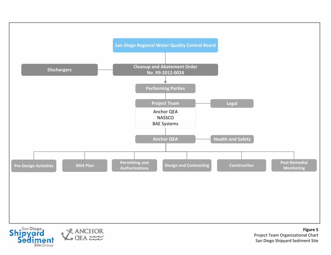
3 PROJECT TEAM AND ORGANIZATION
The CAO identifies “Persons Responsible” as those parties that “caused or permitted the
discharge of waste to the Shipyard Sediment Site resulting in the accumulation of waste in
the marine sediment” (Water Board 2012a). The parties listed in the CAO are NASSCO; BAE
Systems; the City; Campbell Industries; San Diego Gas and Electric, a subsidiary of Sempra
Energy Company; the U.S. Navy; and the Port. Collectively, these parties are referred to as
the “Dischargers.”
Figure 5 presents an organizational chart for the Project Team, which will consist of
representatives from NASSCO and BAE Systems, their respective Project Coordinator, and
other representatives of the Dischargers.
For matters of CAO compliance, the Water Board will serve as a point of communications
and information dissemination for other governmental agencies (as necessary), including the
U.S. Army Corps of Engineers (USACE), National Oceanic and Atmospheric Administration,
and California Department of Fish and Game. Separate matters of permit compliance may be
communicated and managed directly with individual agencies.
San Diego Regional Water Quality Control Board
Figure 5Project Team Organizational ChartSan Diego Shipyard Sediment Site
Cleanup and Abatement OrderNo. R9-2012-0024
Dischargers
Performing Parties
Project Team
Anchor QEANASSCO
BAE Systems
Legal
Anchor QEA Health and Safety
Post Remedial Monitoring
MS4 PlanPermitting and Authorizations
ConstructionDesign and ContractingPre-Design Activities
Remedial Action Plan June 2012 San Diego Shipyard Sediment Site 14
4 IMPLEMENTATION PLAN FOR REMEDIAL ACTION
The Dischargers, both directly and through their Project Coordinator, will maintain close
and regular communication and coordination with the Water Board regarding project
progress and success. At a minimum, communications will include:
Attending briefings with Water Board representatives as necessary
Sending notifications to the Water Board as required under the CAO
Submitting quarterly progress reports
Reviewing and approving of various permit applications necessary to attain required
permits and approvals
Reviewing and approving various technical memoranda developed during the design
and permitting
Reviewing and approving the Cleanup and Abatement Completion Report
4.1 Design Activities and Site Studies
A number of additional site studies will be required to support the first step of the remedial
action: project design and permitting. Pre-design investigations and the subsequent
technical design activities are discussed in detail in the DCR (Appendix A).
4.2 Apply for and Obtain Project Permits
The work will require a series of permits to be applied for concurrent with the design
process. Section 5 provides details on the state and federal permits and approvals that must
be received prior to implementation of the remedial action.
4.3 Coordination with the Public
Public coordination will be an important component of implementing the remedial action.
The CRP (Appendix E) provides detail on coordination with the public.
4.4 Prepare Contract Documents
Once engineering design tasks have been completed, all technical design details, including
performance and monitoring requirements described in this report and the accompanying
QAPP (Appendix B), will be documented in a set of construction plans and technical
specifications. These documents, in conjunction with legal contract language, will comprise
Implementation Plan for Remedial Action
Remedial Action Plan June 2012 San Diego Shipyard Sediment Site 15
a set of contract documents that will be used by the contractor(s) in preparing bids for the
work and that will then form the basis for the execution, monitoring, approval, and payment
for the work.
The construction plans and technical specifications will be prepared as a bid-ready set of
contract documents that can be distributed to potential site contractor(s).
4.5 Award Contract
The construction plans and technical specifications previously described will be used to
create a bid-ready set of contract documents that will be made available to selected, qualified
contractors. The Project Team will select a responsive and responsible contractor for the
work based on the value of their bid and on their capabilities to perform the work.
4.6 Oversee and Monitor Construction
Construction performance standards are described in the CDR (Appendix A). Elements of
construction management, construction oversight, and remedial monitoring are described in
the CQAP (Appendix B) and the RMP (Appendix C).
4.7 Final Cleanup and Abatement Completion Report
After the work has been completed, a Final Cleanup and Abatement Completion Report will
be prepared to verify completion of the remedial action. The report will include the
following information:
Compilation of results of all confirmatory sampling that demonstrates that cleanup
areas have been remediated in compliance with the CAO
Demonstration that all underpier areas have been remediated in compliance with the
CAO
Compilation of results of all confirmatory sampling that demonstrate compliance with
required post-remedial SWACs
4.8 Post‐Remedial Monitoring Plan
The CAO requires that post-remedial monitoring be conducted at the Shipyard Sediment
Site. Details are provided in the Post-Remedial Monitoring Plan (Exponent 2012).
Remedial Action Plan June 2012 San Diego Shipyard Sediment Site 16
5 REGULATORY PERMITS AND APPROVALS
The following state and federal permits and approvals must be received prior to
implementation of the remedial action.
5.1 California Environmental Quality Act
The Water Board has determined that an Environmental Impact Report (EIR) is required to
comply with the California Environmental Quality Act, with the Water Board acting as the
lead agency. On November 16, 2011, the Water Board certified the Final Program EIR and
adopted the Findings of Fact, Statement of Overriding Considerations, and Mitigation
Monitoring and Reporting Plan as incorporated within the Resolution. The work will
comply with the preferred alternative selected in the EIR.
5.2 Rivers and Harbors Act Section 10 and Clean Water Act Section 404
Permits
Rivers and Harbors Act Section 10 and Clean Water Act Section 404 permits are needed for
the work. The USACE will act as the lead agency for obtaining these permits and will be the
lead agency for required Endangered Species Act (ESA) and Essential Fish Habitat (EFH)
consultations. Because construction activities are a required component of the CAO, the
USACE has the ability to issue a letter of verification for Nationwide Permit 38, which
applies to “containment stabilization, or removal of hazardous or toxic waste materials that
are performed, ordered, or sponsored by a government agency with established legal or
regulatory authority (notice)” (Federal Register 77:34). The USACE does, however, also have
the discretion to require a Standard Individual Permit.
The USACE will act as the lead National Environmental Policy Act (NEPA) agency. The
USACE’s decision on permit forms affects the form of the NEPA review. An Environmental
Impact Statement is not anticipated to be required.
5.3 Endangered Species Act/Magnusson‐Stevens Fishery Conservation and
Management Act
Consultation under Section 7 of the ESA and under the Magnusson-Stevens Fishery
Conservation and Management Act is required for this work. Consultations concern
Regulatory Permits and Approvals
Remedial Action Plan June 2012 San Diego Shipyard Sediment Site 17
potential effects to federally listed, threatened, or endangered species and EFH issues. The
USACE will act as the lead agency for consultations with the U.S. Fish and Wildlife Service
and National Marine Fisheries Service and will make the final determination on
requirements to comply with these regulations. Project construction activities may be
limited to the period between September 15 and March 31 in order to protect the
endangered California least tern (Sterna antillarum browni); although work within the least
tern season may be requested per the terms of the EIR (Water Board 2012c). A Biological
Assessment and EFH Evaluation Report will be required to support the consultation, and
work windows may be confirmed during that process. Some other sensitive species, such as
sea turtles, are known to be present near the Shipyard Sediment Site, and an eelgrass survey
will be required.
5.4 Section 401 Water Quality Certification and Waste Discharge
Requirements
A Water Quality Certification and Waste Discharge Requirements (WQC/WDRs) permits
are needed for the work. After a review of the QAPP, the Water Board will publish their
WQC/WDRs.
5.5 California Coastal Act Consistency
A California Coastal Act (CCA) consistency determination will be needed for the work. The
Port is anticipated to act as the CCA agency through the Port’s environmental process, as
NASSCO and BAE Systems are Port tenants. The Port can consider the work under its
approved California Coastal Commission approved Port Master Plan.
5.6 Other Reports and Entitlements
A project Stormwater Pollution Prevention Plan and construction and stormwater National
Pollutant Discharge Elimination System permits may be required as a result of the upland
sediment dewatering facility. The need for these items will be confirmed through
discussions with the Water Board. Additionally, access agreements (right-of-entry,
easements, etc.) and some form of a Memorandum of Understanding or lease for the use of an
onshore dewatering facility may also be required by the Port or other land owners adjacent
to the Shipyard Sediment Site.
Remedial Action Plan June 2012 San Diego Shipyard Sediment Site 18
6 Remediation SCHEDULE
The CAO states that implementation of the RAP may commence 60 calendar days after it has
been submitted to the Water Board (unless otherwise directed in writing by the Water
Board). The official timeline for the implementation of the remedial action will begin when
the Project Team receives notification from the Water Board that the RAP has been
approved.
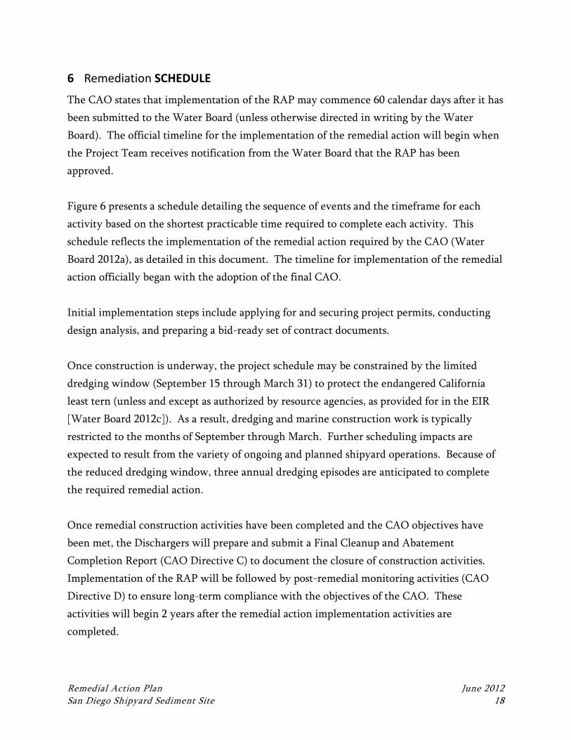
Figure 6 presents a schedule detailing the sequence of events and the timeframe for each
activity based on the shortest practicable time required to complete each activity. This
schedule reflects the implementation of the remedial action required by the CAO (Water
Board 2012a), as detailed in this document. The timeline for implementation of the remedial
action officially began with the adoption of the final CAO.
Initial implementation steps include applying for and securing project permits, conducting
design analysis, and preparing a bid-ready set of contract documents.
Once construction is underway, the project schedule may be constrained by the limited
dredging window (September 15 through March 31) to protect the endangered California
least tern (unless and except as authorized by resource agencies, as provided for in the EIR
[Water Board 2012c]). As a result, dredging and marine construction work is typically
restricted to the months of September through March. Further scheduling impacts are
expected to result from the variety of ongoing and planned shipyard operations. Because of
the reduced dredging window, three annual dredging episodes are anticipated to complete
the required remedial action.
Once remedial construction activities have been completed and the CAO objectives have
been met, the Dischargers will prepare and submit a Final Cleanup and Abatement
Completion Report (CAO Directive C) to document the closure of construction activities.
Implementation of the RAP will be followed by post-remedial monitoring activities (CAO
Directive D) to ensure long-term compliance with the objectives of the CAO. These
activities will begin 2 years after the remedial action implementation activities are
completed.
Figure 6Remediation Schedule
San Diego Shipyard Sediment Site
Year 6Year 1 Year 2 Year 3 Year 4 Year 5
Approval of RAP
Permitting
Design Activities
Construction(September 18 to March 31)
Final Cleanup and Abatement
Completion Report
Post Remedial Monitoring
Year 7
Construction(September 18 to March 31)
Construction(September 18 to March 31)
Remedial Action Plan June 2012 San Diego Shipyard Sediment Site 20
7 REFERENCES
Exponent, 2003. NASSCO and Southwest Marina Detailed Sediment Investigation. Volume
1. Prepared for NASSCO and Southwest Marina, San Diego, California. October
2003.
Exponent, 2012. Post-Remediation Monitoring Plan, San Diego Shipyard Sediment Site.
Prepared for the Regional Water Quality Control Board. June 2012.
Water Board (San Diego Regional Water Quality Control Board), 2012a. Cleanup and
Abatement Order R9-2012-0024 for the Shipyard Sediment Site. March 14, 2012.
Water Board, 2012b. Technical Report for Cleanup and Abatement Order No. R9-2012-0024
for the Shipyard Sediment Site. March 14, 2012.
Water Board, 2012c. Final Environmental Impact Report. March 14, 2012.
DESIGN CRITERIA REPORT
SAN DIEGO SHIPYARD SEDIMENT SITE
Cleanup and Abatement Order No. R9‐2012‐0024
Prepared by
Anchor QEA, L.P.
26300 La Alameda, Suite 240
Mission Viejo, California 92691
June 12, 2012
Design Criteria Report June 2012 San Diego Shipyard Sediment Site i
TABLE OF CONTENTS
1 INTRODUCTION .................................................................................................................. 1
2 DREDGING DESIGN ............................................................................................................. 1
2.1 Design Criteria ..................................................................................................................1
2.2 Dredging Design Process .................................................................................................2
2.3 Contingencies ...................................................................................................................5
2.4 Construction Implementation .........................................................................................6
2.4.1 Equipment ...................................................................................................................6
2.4.2 Waste Generated ........................................................................................................6
2.5 Performance Standards ....................................................................................................6
3 SEDIMENT MANAGEMENT AND DISPOSAL ................................................................... 7
3.1 Design Criteria ..................................................................................................................7
3.2 Design Process ..................................................................................................................7
3.3 Selection of Sediment Offloading and Stockpiling Area ................................................8
3.4 Contingencies ...................................................................................................................9
3.5 Construction Implementation .........................................................................................9
3.5.1 Equipment ...................................................................................................................9
3.5.2 Waste Generated ........................................................................................................9
3.6 Performance Standards ..................................................................................................10
4 CLEAN LAYER PLACEMENT UNDER PIERS .................................................................. 12
4.1 Design Criteria ................................................................................................................12
4.2 Design Process ................................................................................................................12
4.3 Construction Implementation .......................................................................................12
4.4 Performance Standards ..................................................................................................12
5 STRUCTURAL PROTECTION ............................................................................................ 13
5.1 Design Criteria ................................................................................................................13
5.2 Design Process ................................................................................................................13
5.3 Construction Implementation .......................................................................................14
5.4 Performance Standards ..................................................................................................14
6 ENVIRONMENTAL PROTECTION ................................................................................... 15
6.1 Contractor Controls and Best Management Practices .................................................15
Table of Contents
Design Criteria Report June 2012 San Diego Shipyard Sediment Site ii
6.1.1 Water Quality Criteria .............................................................................................15
6.1.2 Specialized Equipment .............................................................................................15
6.2 Performance Standards ..................................................................................................16
7 SCHEDULE AND COORDINATION ................................................................................. 17
7.1 Schedule ..........................................................................................................................17
7.2 Coordination ...................................................................................................................17
7.3 Site Security ....................................................................................................................18
8 REFERENCES ...................................................................................................................... 19
List of Tables
Table 1 Estimated Design Depths and Dredge Volumes ................................................... 1
List of Figures
Figure 1 Site Map .................................................................................................................. 0
Figure 2 Thiessen Polygon and Required Cleanup Areas .................................................. 3
Figure 3 Proposed Sediment Offloading Area .................................................................. 11
Design Criteria Report June 2012 San Diego Shipyard Sediment Site
LIST OF ACRONYMS AND ABBREVIATIONS
BMP best management practice
CAO Cleanup and Abatement Order
City City of San Diego
DCR Design Criteria Report
EIR Environmental Impact Report
QAPP Quality Assurance Project Plan
Port San Diego Unified Port District
RAP Remedial Action Plan
RMP Remediation Monitoring Plan
SDG&E San Diego Gas and Electric
Shipyard Sediment Site San Diego Shipyard Sediment Site
TUOP Tidelands Use and Occupancy Permit
Water Board San Diego Regional Water Quality Control Board
Design Criteria Report June 2012 San Diego Shipyard Sediment Site 1
1 INTRODUCTION
In March 2012, the San Diego Regional Water Quality Control Board (Water Board) issued
Cleanup and Abatement Order (CAO) No. R9-2012-0024 for the remediation of marine
sediments containing elevated chemical concentrations within the San Diego Shipyard
Sediment Site (Shipyard Sediment Site) in San Diego, California (Water Board 2012a). The
Shipyard Sediment Site includes the waters adjacent to two adjoining, active shipyard
facilities in San Diego Bay—the North Shipyard (owned BAE Systems San Diego Ship Repair
Facility) and the South Shipyard (owned National Steel and Shipbuilding Company Shipyard
Facility). Figure 1 depicts the location of the Shipyard Sediment Site and the layout of the
North and South Shipyard Areas. The Shipyard Sediment Site remedial footprint extends
from the U.S. Bulkhead Line (shoreline) to San Diego Bay’s main shipping channel to the
west.
This Design Criteria Report (DCR) is one component of the Remedial Action Plan (RAP) for
the San Diego Shipyards Sediment Site. This document describes technical criteria for design
and construction and the process of developing appropriate design elements to ensure the
work is successfully completed. This report is organized as follows:
Section 1: Introduction
Section 2: Dredging Design
Section 3: Sediment Management and Disposal
Section 4: Clean Layer Placement Under Piers
Section 5: Structural Protection
Section 6: Environmental Protection
Section 7: Schedule and Coordination
Section 8: References

SDG&EParcel
Figure 1Site Map
San Diego Shipyard Sediment Site
Q:\Job
s\0201
96-01
_BAE
_Syste
ms\M
aps\RA
P\Loca
ton_M
ap.mx
d nko
chie 6/
12/201
2 12:
55:14
PM
0 200 400 600 800Feet
[
! ! Shipyard Leasehold LineShipyard Sediment Site
§̈¦5 §̈¦805
§̈¦8§̈¦15
§̈¦15
Pacific OceanPacific Ocean
San Diego Bay
San Diego Bay
Chula Vista
National City
CoronadoBonita
San Diego
Buildin
g Ways
4 Buildin
g Ways
3On B
lock
Building
Dock 1Be
rth W
all
Berth I
Berth
III
Berth
IV
Berth
V
Berth
VI
Berth VII
Berth
IXBerth
X
Pier 3
City Outfall
Pier 2
Pier 1
Extent of Shipyard Sediment Site
ShipyardSediment
Site
NORTHSHIPYARD
AREA(SEE FIGURE 2)
SOUTHSHIPYARD
AREA(SEE FIGURE 3)
North Shipyard Leasehold LineSouth Shipyard Leasehold Line
San DiegoCoronado
National City
Chula Vista
Bonita
Design Criteria Report June 2012 San Diego Shipyard Sediment Site 1
2 DREDGING DESIGN
2.1 Design Criteria
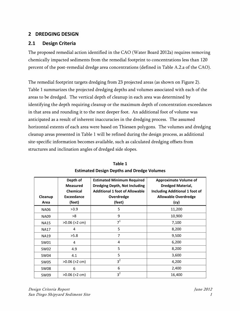
The proposed remedial action identified in the CAO (Water Board 2012a) requires removing
chemically impacted sediments from the remedial footprint to concentrations less than 120
percent of the post-remedial dredge area concentrations (defined in Table A.2.a of the CAO).
The remedial footprint targets dredging from 23 projected areas (as shown on Figure 2).
Table 1 summarizes the projected dredging depths and volumes associated with each of the
areas to be dredged. The vertical depth of cleanup in each area was determined by
identifying the depth requiring cleanup or the maximum depth of concentration exceedances
in that area and rounding it to the next deeper foot. An additional foot of volume was
anticipated as a result of inherent inaccuracies in the dredging process. The assumed
horizontal extents of each area were based on Thiessen polygons. The volumes and dredging
cleanup areas presented in Table 1 will be refined during the design process, as additional
site-specific information becomes available, such as calculated dredging offsets from
structures and inclination angles of dredged side slopes.
Table 1
Estimated Design Depths and Dredge Volumes
Cleanup
Area
Depth of
Measured
Chemical
Exceedance
(feet)
Estimated Minimum Required
Dredging Depth, Not Including
Additional 1 foot of Allowable
Overdredge
(feet)
Approximate Volume of
Dredged Material,
Including Additional 1 foot of
Allowable Overdredge
(cy)
NA06 >3.9 5 11,200
NA09 >8 9 10,900
NA15 >0.06 (>2 cm) 71 7,100
NA17 4 5 8,200
NA19 >5.8 7 9,500
SW01 4 4 6,200
SW02 4.9 5 8,200
SW04 4.1 5 3,600
SW05 >0.06 (>2 cm) 32 4,200
SW08 6 6 2,400
SW09 >0.06 (>2 cm) 32 16,400
Dredging Design
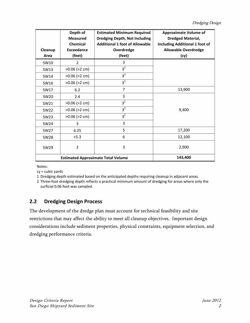
Design Criteria Report June 2012 San Diego Shipyard Sediment Site 2
Cleanup
Area
Depth of
Measured
Chemical
Exceedance
(feet)
Estimated Minimum Required
Dredging Depth, Not Including
Additional 1 foot of Allowable
Overdredge
(feet)
Approximate Volume of
Dredged Material,
Including Additional 1 foot of
Allowable Overdredge
(cy)
SW10 2 3
SW13 >0.06 (>2 cm) 32
SW14 >0.06 (>2 cm) 32
SW16 >0.06 (>2 cm) 32
SW17 6.2 7 13,900
SW20 2.4 3
9,400
SW21 >0.06 (>2 cm) 32
SW22 >0.06 (>2 cm) 32
SW23 >0.06 (>2 cm) 32
SW24 3 3
SW27 4.25 5 17,200
SW28 <5.3 6 12,100
SW29 2 3 2,900
Estimated Approximate Total Volume 143,400
Notes: cy = cubic yards 1 Dredging depth estimated based on the anticipated depths requiring cleanup in adjacent areas. 2 Three‐foot dredging depth reflects a practical minimum amount of dredging for areas where only the
surficial 0.06 foot was sampled.
2.2 Dredging Design Process
The development of the dredge plan must account for technical feasibility and site
restrictions that may affect the ability to meet all cleanup objectives. Important design
considerations include sediment properties, physical constraints, equipment selection, and
dredging performance criteria.

!.
!.
!.
!.
!. !.
!.
!.
!.
!.
!.
!.
!.
!.!.
!.
!.
!.
!.
!.
!.
!.
!.
!.
!.
!.
!.
!.
!.
!.
!.
!.
!.
!.
!.
!.
!.
!.
!.
!.
!.
!.
!.
!.
!.
!.
!.!.
!.
!.
!.!.
!.
!.
!.
!.
!.
!.
!.
!.
!.
!.
!.
!.
!.
!.
!.
Floati
ng D
ry Do
ck
SW07
SW06
SW26
SW05 SW14 SW16
SW15
SW22
SW09
SW13
SW18
SW21
SW23
SW11SW03
SW36
SW34
SW31
SW33
SW32
SW30
SW29
SW28
SW25
SW24
SW12
SW08SW04
SW02
SW27
SW20
SW19
SW17
SW10
NA21
NA20
NA19
NA17
NA09
NA16
NA06
NA04
NA23
NA24
NA01
NA13NA29
NA02
NA31
NA25
NA30NA26NA14
NA08
NA10
NA18
NA22
NA19
NA15
NA05
NA07
NA12
NA11
SW01
NA03
NA28
NA27
Figure 2Thiessen Polygon and Required Cleanup Areas
San Diego Shipyard Sediment Site
\\Orca
s\GIS\
Jobs\0
20196
-01_B
AE_Sy
stems
\Maps
\2010
_11\Th
iessen
_Rem
edial_
Footpr
int.m
xd nk
ochie
11/11
/2010
2:46 P
M
0 150 300 450 600Feet
[
!. Sampling Location! ! Shipyard Leasehold Line
Thiessen PolygonsThiessen Polygons to be Remediated
Buildin
g Ways
4 Buildin
g Ways
3On B
lock
Building
Dock 1Be
rth W
all
Berth I
Berth
III
Berth
IV
Berth
V
Berth
VI
Mouth
of C
holla
s Cre
ek
Berth VII
Berth
IXBe
rth X
Pier 3
City OutfallPier 2
Pier 1
Extent of Shipyard Sediment Study Area
Coronado
SanDiego
ChulaVista
NationalCity
SanSanDiegoDiegoBayBay
PacificPacificOceanOcean
§̈¦15§̈¦8
§̈¦805
§̈¦5
Site
Dredging Design
Design Criteria Report June 2012 San Diego Shipyard Sediment Site 4
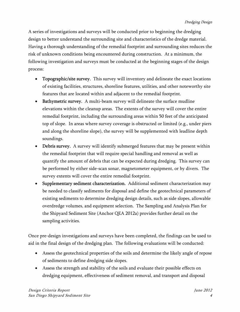
A series of investigations and surveys will be conducted prior to beginning the dredging
design to better understand the surrounding site and characteristics of the dredge material.
Having a thorough understanding of the remedial footprint and surrounding sites reduces the
risk of unknown conditions being encountered during construction. At a minimum, the
following investigation and surveys must be conducted at the beginning stages of the design
process:
Topographic/site survey. This survey will inventory and delineate the exact locations
of existing facilities, structures, shoreline features, utilities, and other noteworthy site
features that are located within and adjacent to the remedial footprint.
Bathymetric survey. A multi-beam survey will delineate the surface mudline
elevations within the cleanup areas. The extents of the survey will cover the entire
remedial footprint, including the surrounding areas within 50 feet of the anticipated
top of slope. In areas where survey coverage is obstructed or limited (e.g., under piers
and along the shoreline slope), the survey will be supplemented with leadline depth
soundings.
Debris survey. A survey will identify submerged features that may be present within
the remedial footprint that will require special handling and removal as well as
quantify the amount of debris that can be expected during dredging. This survey can
be performed by either side-scan sonar, magnetometer equipment, or by divers. The
survey extents will cover the entire remedial footprint.
Supplementary sediment characterization. Additional sediment characterization may
be needed to classify sediments for disposal and define the geotechnical parameters of
existing sediments to determine dredging design details, such as side slopes, allowable
overdredge volumes, and equipment selection. The Sampling and Analysis Plan for
the Shipyard Sediment Site (Anchor QEA 2012a) provides further detail on the
sampling activities.
Once pre-design investigations and surveys have been completed, the findings can be used to
aid in the final design of the dredging plan. The following evaluations will be conducted:
Assess the geotechnical properties of the soils and determine the likely angle of repose
of sediments to define dredging side slopes.
Assess the strength and stability of the soils and evaluate their possible effects on
dredging equipment, effectiveness of sediment removal, and transport and disposal
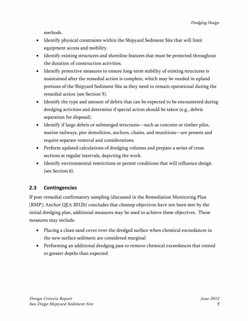
Dredging Design
Design Criteria Report June 2012 San Diego Shipyard Sediment Site 5
methods.
Identify physical constraints within the Shipyard Sediment Site that will limit
equipment access and mobility.
Identify existing structures and shoreline features that must be protected throughout
the duration of construction activities.
Identify protective measures to ensure long-term stability of existing structures is
maintained after the remedial action is complete, which may be needed in upland
portions of the Shipyard Sediment Site as they need to remain operational during the
remedial action (see Section 5).
Identify the type and amount of debris that can be expected to be encountered during
dredging activities and determine if special action should be taken (e.g., debris
separation for disposal).
Identify if large debris or submerged structures—such as concrete or timber piles,
marine railways, pier demolition, anchors, chains, and munitions—are present and
require separate removal and considerations.
Perform updated calculations of dredging volumes and prepare a series of cross
sections at regular intervals, depicting the work.
Identify environmental restrictions or permit conditions that will influence design
(see Section 6).
2.3 Contingencies
If post-remedial confirmatory sampling (discussed in the Remediation Monitoring Plan
[RMP]; Anchor QEA 2012b) concludes that cleanup objectives have not been met by the
initial dredging plan, additional measures may be used to achieve these objectives. These
measures may include:
Placing a clean sand cover over the dredged surface when chemical exceedances in
the new surface sediment are considered marginal
Performing an additional dredging pass to remove chemical exceedances that extend
to greater depths than expected
Dredging Design
Design Criteria Report June 2012 San Diego Shipyard Sediment Site 6
2.4 Construction Implementation
2.4.1 Equipment
Dredging will be performed via barge-mounted, mechanical dredging equipment, with either
a clamshell bucket or cable-arm bucket suspended from a crane. Sediments will be removed
with the bucket and placed into a scow or barge positioned adjacent to the dredging
equipment.
2.4.2 Waste Generated
Wastes generated during dredging activities are expected to include:
Sediment
Debris, which includes all material that is not sediment (e.g., rocks) and anything that
is manmade (e.g., anchors, chains, plastic bags)
Debris encountered within the cleanup areas will be required (per the technical
specifications) to be disposed of at an upland approved facility, such as a Subtitle D landfill
(see Section 3). Wastes generated as a result of the contractor’s activities (e.g., oil or fuel
spill) will be their responsibility to manage, cleanup, and dispose of properly. Procedures for
such cleanup activities will be documented in the contractor’s Dredging and Disposal Work
Plan, which will be subject to review and approval by the Project Team.
2.5 Performance Standards
The Quality Assurance Project Plan (QAPP) for the Shipyard Sediment Site (Anchor QEA
2012c) details procedures that will be implemented to verify that the dredging activities have
been completed to the horizontal and vertical extents specified in the technical
specifications. The RMP (Anchor QEA 2012b) describes procedures that will be
implemented to verify the post-remedial sediment surface is in compliance with the cleanup
objectives.
Design Criteria Report June 2012 San Diego Shipyard Sediment Site 7
3 SEDIMENT MANAGEMENT AND DISPOSAL
3.1 Design Criteria
Dredged material will be offloaded to an onshore stockpiling location where it will be
dewatered, loaded into trucks, and transported to one or more off-site disposal locations.
This disposal method will require classifying the material for disposal, identifying a candidate
landfill for disposal, and identifying and using a land-side area for sediment offloading and
stockpiling. Neither the North or South Shipyard Areas has available on-land area that
would suffice for this processing; therefore, arrangements must be made with a third-party
for use of an off-site stockpiling area. The area tentatively identified for off-loading,
classification, and disposal preparation of dredged material is immediately to the north of the
North Shipyard Area (see Section 3.3). This area, while currently used for parking and
shipyard operations, is under sublease from San Diego Gas and Electric (SDG&E) and has
been identified for use because of its proximity to the Shipyard Sediment Site and immediate
access to San Diego Bay. No other location has been identified that is more appropriate for
this purpose. However, use of this area must be authorized by or between SDG&E and the
Port, as BAE System has limited use rights that do not include use as required for sediment
management.
The sediment offloading and stockpiling area will be outfitted to contain the sediment and
any water (effluent) that drains from it, through the use of best management practices
(BMPs; e.g., closed perimeter barriers, base liner, sand, asphalt, liners, and water handling
facilities).
3.2 Design Process
At a minimum, the following evaluations will be conducted to manage sediment disposal:
Determine material suitability for disposal and identify suitable disposal location,
which will require evaluating results from the sediment characterization investigation
(discussed in Section 2) and consulting with landfill representatives to determine if
material properties (chemical and physical) meet their requirements for disposal as
either daily cover material, as solid waste at a local landfill (such as the Otay Landfill
in San Diego County), or if any of the sediment qualifies as California hazardous
waste and requires disposal at a more remote regional landfill.
Sediment Management and Disposal
Design Criteria Report June 2012 San Diego Shipyard Sediment Site 8
Determine whether debris encountered during dredging needs to be segregated and
disposed of separately.
Evaluate whether the use of admixtures (e.g., cement and lime) will be beneficial in
accelerating the removal of “free liquids” from the dredged material.
3.3 Selection of Sediment Offloading and Stockpiling Area
During the design process, the selection of an offloading and stockpiling location will be
finalized. Ideally such an area would meet the following criteria:
Situated on or adjacent to a waterfront dock, wharf, or seawall with sufficient depth
to enable a sediment-loaded barge to pull immediately adjacent for offloading. The
waterfront area should be long enough to allow the mooring of one to two barges at a
time.
Structurally capable of holding offloading equipment (such as a crane), the sediment
stockpiles, and any ancillary dewatering equipment (if used).
Situated at or on a road or rail spur so that trucks or railcars can be brought in and
loaded with dewatered sediment for haul-off and disposal.
Enough square footage to hold dredged material for enough time to undergo
dewatering, whether that be through passive dewatering (by air-drying action
supplemented by regular reworking, potentially accelerated with the use of water
absorbent additives or cement) or via a more active process involving filter presses or
other equipment. The passive air-drying dewatering process is the slowest; the
amount of time needed for this process is dependent on weather conditions and
physical character of the sediment.
Enough square footage to allow haul-off and disposal of sediment at the same overall
rate as the sediment is being dredged as well as enough space to accommodate
segregated stockpiles if some sediment does not pass the requirements for disposal at
local landfills.
An area available for the full duration of the work. The necessary duration of leasing
the off-site stockpiling area should include an additional month before and after
construction for setup, preparation, breakdown, and cleanup.
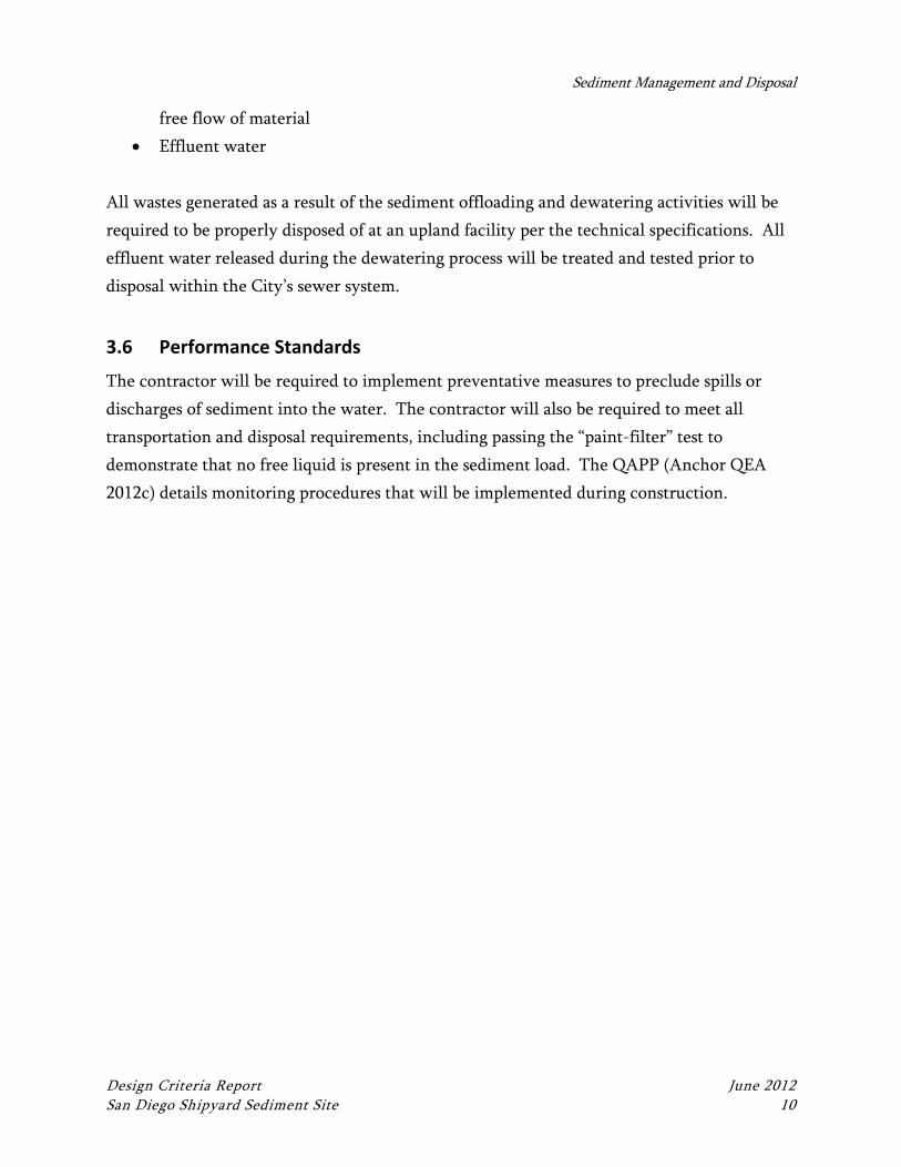
The proposed stockpiling area is located to the north of the North Shipyard Area. This
location is on Port Tidelands property, under Tidelands Use and Occupancy Permit (TUOP)
Sediment Management and Disposal
Design Criteria Report June 2012 San Diego Shipyard Sediment Site 9
to SDG&E and subsequent subpermit to BAE Systems. The proposed stockpiling area is
presented on Figure 3. Some improvements are anticipated to be needed prior to using the
area for off-loading, dewatering, temporary storage, and perimeter containment.
Improvements may include dredging, bulkhead improvements, grading, and surface paving.
The area will also have to be incorporated into existing and future regulatory permits.
3.4 Contingencies
The contractor may elect to use chemical admixtures to accelerate the dewatering process. A
pilot test may be considered to determine the correct ratio of mix to sediment. This
contingency will be more crucial if the identified stockpiling area is small enough to limit
production rates.
3.5 Construction Implementation
3.5.1 Equipment
Dredged material will be offloaded to an onshore stockpiling location where it will be
dewatered, loaded into trucks, and transported to one or more off-site disposal locations.
The dredged material will be unloaded from the haul barges using a rehandling bucket and
could either be stockpiled on site or placed in shipping containers lined with plastic sheets
for dewatering. Any ponded water in the haul barges may need to be pumped off of the
barge to avoid barge overflow, as will likely be required per permit conditions. The rest of
the dewatering process will occur by gravity drainage and open-air drying while the material
is stockpiled on land. All water (effluent) that drains from the sediment stockpiles on land
will be contained and ultimately disposed of in either the City’s sewer system after testing, or
at an off-site disposal facility, as necessary. Once sediments have been sufficiently
dewatered, they are anticipated to be loaded onto trucks or railcars for transport to the
appropriate landfill for disposal.
3.5.2 Waste Generated
Wastes generated during offloading and dewatering activities are expected to include:
Sediment
Debris
Used hay bales/straw waddle, filter fabric, or other similar materials used to prevent
Sediment Management and Disposal
Design Criteria Report June 2012 San Diego Shipyard Sediment Site 10
free flow of material
Effluent water
All wastes generated as a result of the sediment offloading and dewatering activities will be
required to be properly disposed of at an upland facility per the technical specifications. All
effluent water released during the dewatering process will be treated and tested prior to
disposal within the City’s sewer system.
3.6 Performance Standards
The contractor will be required to implement preventative measures to preclude spills or
discharges of sediment into the water. The contractor will also be required to meet all
transportation and disposal requirements, including passing the “paint-filter” test to
demonstrate that no free liquid is present in the sediment load. The QAPP (Anchor QEA
2012c) details monitoring procedures that will be implemented during construction.
SOURCE: Drawing prepared from Bing maps.
HORIZONTAL DATUM: California State Plane Zone 6, NAD83.
LEGEND:
Property line
Parcel line
Sediment offloading and staging area
0
Scale in Feet
80
Jun 12, 2012 11:57am
ghow
ell L:\A
utoC
AD
P
roject F
iles\_P
rojects\0918-G
allagher\S
D S
hipyard\0918-R
P-001-S
DG
E.dw
g F
IG
3
Figure 3
Proposed Sediment Offloading Area
San Diego Shipyard Sediment Site
Design Criteria Report June 2012 San Diego Shipyard Sediment Site 12
4 CLEAN LAYER PLACEMENT UNDER PIERS
4.1 Design Criteria
Sediment removal under piers and overwater structures is impractical and technically
infeasible; therefore, an alternative remedial approach is needed to achieve cleanup
objectives in these areas. To promote mixing and natural recovery of contaminated
sediments under piers and overwater structures within the remedial footprint, a layer of
clean sand and gravel will be placed on the surface of the existing sediment layer. Ongoing
processes of sediment mixing and transport is anticipated to result in a mixed surface under
the piers, which will allow long-term achievement of the cleanup objectives.
4.2 Design Process
At a minimum, the following evaluations will be conducted to specify the clean layer
placement:
Obtain and review as-built construction plans for overwater structures.
Assess the substrate conditions of the underpier areas and determine where
protection measures are appropriate.
Identify readily available and cost-effective materials that can be used to serve the
cleanup objectives.
Identify implementable construction and placement methods.
4.3 Construction Implementation
Clean layer of material will be placed to the required thickness by pumping, conveying, or
laying the sand/gravel material over the areas using a tremie pump, conveyor, or long-reach
bucket arm (or other customized equipment) advanced under the structures. The material
will be transported to the Shipyard Sediment Site by truck and transferred to barge for
placement or direct placement from shore.
4.4 Performance Standards
The contractor will be required to place the clean layer material to the horizontal and
vertical extents required by the technical specifications. The QAPP (Anchor QEA 2012c)
details monitoring procedures that will be implemented during construction.
Design Criteria Report June 2012 San Diego Shipyard Sediment Site 13
5 STRUCTURAL PROTECTION
5.1 Design Criteria
Dredging near any shoreline structure has the potential to create an unstable condition due
to the removal of passive earth pressures or undermining of the structure. In addition to
moving dry docks to gain access to underpier areas, precautionary measures will be taken to
retain the stability of the structures when dredging along the shoreline and near marine
structures to ensure their long-term stability. Such measures are expected to take the form of
the recommendations in Moffat and Nichols Engineers’ 2002 structural review. They would
include specifying dredging offsets to prevent damage from impacts of dredging equipment
or installing a protective rock backfill along the side slopes and wharf faces to protect against
unstable conditions that may result from material removal. Alternatively, a clean sand cover
may be required to meet cleanup objectives in areas where dredging would significantly
impact infrastructure and overwater structures.
5.2 Design Process
Similar to the beginning stages of dredging design, a pre-design investigation will be
performed by a professional structural engineer to assess the condition of all vessel berthing
slips and facilities located within and immediately adjacent to the remedial footprint. At a
minimum, the following evaluations will be conducted:
Obtain and review as-built drawings of all existing site features and confirm
conditions with either surveys or a visual site investigation.
Perform a visual structural assessment of the overwater structures to determine
existing condition of all structures and whether additional in-depth investigations are
needed.
Perform a reconnaissance of the underpier areas to determine current conditions of
the structures that may include inspecting the substrate bottom along the mudline to
determine the presence of debris and/or rock and topography. (Divers may be used for
this purpose.).
The following evaluations will be completed by a professional structural engineer:
Review the geometry and condition of marine structures near and beneath which the
work will be completed.
Structural Protection
Design Criteria Report June 2012 San Diego Shipyard Sediment Site 14
Assess geotechnical information of sediment strength to determine stability of
structures in response to adjacent dredging.
Assess the rapid visual structural assessment and diver reconnaissance survey findings
and provide recommendations on either offset distances for dredging or other
protective measures (if necessary, specify maximum allowable length of time after
dredging is completed in the immediately adjacent area to minimize the time span
during which the structures or slopes are unprotected).
Assess whether retrofitting or otherwise improving selected structures, or portions
thereof, is required to preserve their condition.
5.3 Construction Implementation
The protection material may be transported to the Shipyard Sediment Site by either trucks
and transferred to barge for placement or brought directly by barges. Placement of
protective materials will likely be accomplished by using a clamshell bucket or long-reach
bucket arm, as material will have to be placed to achieve the proper thickness and extents in
accordance with design requirements.
5.4 Performance Standards
The dredging plan will be designed such that existing structures are not undermined or
otherwise disturbed as a result of the work. The contractor will be required to protect all
structures and place any protective material to the horizontal and vertical extents required
by the technical specifications. The QAPP (Anchor QEA 2012c) details monitoring
procedures that will be implemented during construction.
Design Criteria Report June 2012 San Diego Shipyard Sediment Site 15
6 ENVIRONMENTAL PROTECTION
Dredging and transport of sediments is expected to create turbidity in the water column, an
effect that will be short-term in duration but must be minimized by the contractor through
the use of operational BMPs and institutional controls. Water quality conditions will be
monitored throughout construction, and the contractor will be required to meet all
applicable water quality standards specified in the Section 401 Water Quality Certification
for the work or substantive equivalent.
6.1 Contractor Controls and Best Management Practices
To ensure water quality standards are maintained throughout construction, permits and the
technical specifications will require the contractor to implement a water quality control plan
and follow BMPs. The contractor’s performance will be documented by a Water Board-
required water quality monitoring program, which will either be implemented by the
contractor or the Project Team.
6.1.1 Water Quality Criteria
Water quality monitoring will be conducted in accordance with the Environmental Impact
Report (EIR; Water Board 2012b) and with regulatory permits obtained for this work.
Specifically, water quality monitoring will be required through the Section 401 Water
Quality Certification issued by the Water Board. When not in compliance with the water
quality criteria, the contractor will be required to correct the condition. The frequency of
water quality monitoring will initially be high (e.g., once per day) but may be lessened as
dredging proceeds and data are collected to document the results, provided that few water
quality exceedances are noted. The RMP (Anchor QEA 2012b) presents more detail on the
elements of the expected water quality monitoring requirements for the Shipyard Sediment
Site and contractor controls that can be implemented to bring water quality back into
compliance.
6.1.2 Specialized Equipment
Double floating silt curtains will be required during dredging activities to help control loss of
suspended solids beyond the immediate work area. As part of the technical specifications,
the contractor is required to maintain the silt curtains around all dredging work as to reduce
Privileged and Confidential Mediation Communication Environmental Protection
Design Criteria Report June 2012 San Diego Shipyard Sediment Site 16
the potential for water quality impacts and the escape of significant suspended solids beyond
the remedial footprint.
Numerous BMPs will be incorporated into the technical specifications and will be
implemented by the contractor during construction for the purpose of protecting water
quality at the site. Possible BMPs are discussed in detail in the RMP (Anchor QEA 2012b).
The contractor will also be required to use a cable-arm clamshell bucket (frequently referred
to as an environmental bucket). This bucket design typically reduces loss of sediment and
turbid water during closing and withdrawal of the bucket from the water. However, a cable-
arm bucket may not be sufficiently strong to excavate denser sediments or large debris. A
standard clamshell bucket may be needed at times, which will be subject to the contractor’s
choice and discretion.
The contractor will supplement appropriate sequencing and production rates to ensure water
quality criteria requirements are maintained.
6.2 Performance Standards
The contractor will be required to abide by all permits and EIR mitigation measures (e.g.
water quality, biological monitoring, construction noise, air quality; Water Board 2012b).
The RMP (Anchor QEA 2012b) details how these measures will be monitored during
construction.
Design Criteria Report June 2012 San Diego Shipyard Sediment Site 17
7 SCHEDULE AND COORDINATION
7.1 Schedule
Ongoing shipyard activities associated with the active shipyard (e.g., scheduling vessel
berthing timeframes and related shipyard work) will be taken into consideration when
coordinating and scheduling during construction.
Environmental protection of the California least tern (Sterna antillarum browni) will also
restrict construction. Dredging and marine construction work is typically restricted to the
months of September through March, allowing for a construction window of 7 months per
year that avoids critical nesting periods (except as may be authorized by the resource
agencies). Because of these operational and environmental work restrictions, final
compliance with the CAO may require up to three construction seasons (or more) before all
sediment is removed from the cleanup areas given the expected extent of dredging needed to
accomplish this cleanup (143,400 cubic yards, plus more if additional dredging is needed) and
the array of ongoing shipyard activities that will likely impede production. While the
respective shipyards will work to accommodate the dredging, the work will also likely be
impacted by ongoing operations.
7.2 Coordination
Ongoing shipyard operations and vessel traffic within the Shipyard Sediment Site will have
an impact on dredging activities and daily productivity. Communication and advanced
planning will be crucial to the completion of the work. The technical specifications will
detail to the extent possible the expected vessel berthing schedules and measures to ensure
shipyard operations are not impeded. Where possible, the specifications will detail the
following:
Daily vessel traffic
Windows of work where cleanup areas around overwater structures will be available
for construction activities
Timeframes when navigational channels or other areas can be occupied by the
contractor or likewise times when areas must remain open as to not impede shipyard
operations
Other construction and/or contractors that are also working at the Shipyard Sediment
Schedule and Coordination
Design Criteria Report June 2012 San Diego Shipyard Sediment Site 18
Site and where construction activities must be coordinated
7.3 Site Security
As a result of U.S. Naval security requirements, the Shipyard Sediment Site is controlled by a
perimeter security boom (Force Protection Barrier) that provides demarcation of the security
access points. Additionally, when dredging (or any other vessel/small boat traffic) is
occurring within the Shipyard Sediment Site, and especially when in close proximity any
Naval ship, heightened security communications are required. Such communication will
include advance notice to all vessels within the Shipyard Sediment Site and stand-off
distances from Naval ships.
Additional coordination measures that are planned during construction are detailed in the
QAPP (Anchor QEA 2012c).
Design Criteria Report June 2012 San Diego Shipyard Sediment Site 19
8 REFERENCES
Anchor QEA, L.P., 2012a. Sampling and Analysis Plan for the San Diego Shipyard Sediment
Site. June 2012.
Anchor QEA, 2012 Remediation Monitoring Plan for the San Diego Shipyard Sediment Site.
June 2012.
Anchor QEA, 2012c. Quality Assurance Project Plan for the San Diego Shipyard Sediment
Site. June 2012.
Moffat and Nichol Engineers, 2002. Review of Impacts to Waterfront Structures Subjected
to Variable Dredging Depths, NASSCO, San Diego, California. Final Report. August
2002.
Water Board (San Diego Regional Water Quality Control Board), 2012a. Cleanup and
Abatement Order R9-2012-0024 for the Shipyard Sediment Site. March 14, 2012.
Water Board, 2012b. Final Environmental Impact Report. March 14, 2012.
QUALITY ASSURANCE PROJECT PLAN
SAN DIEGO SHIPYARD SEDIMENT SITE
Cleanup and Abatement Order No. R9‐2012‐0024
Prepared by
Anchor QEA, L.P.
26300 La Alameda, Suite 240
Mission Viejo, California 92691
June 12, 2012
Quality Assurance Project Plan June 2012 San Diego Shipyard Sediment Site i
TABLE OF CONTENTS
1 INTRODUCTION .................................................................................................................. 1
2 ELEMENTS OF THE QUALITY ASSURANCE PROJECT PLAN ........................................ 4
3 PROJECT ROLES AND RESPONSIBILITIES ....................................................................... 5
3.1 Regulatory Oversight .......................................................................................................5
3.2 Construction Contractor ..................................................................................................5
3.3 Subcontractors ..................................................................................................................6
4 CONTRACTOR/SUBCONTRACTOR QUALIFICATIONS ................................................. 7
5 DOCUMENTATION AND REPORTING ............................................................................. 8
5.1 Documentation and Submittals prior to Construction ..................................................8
5.1.1 Dredging Management Plan ......................................................................................8
5.1.2 EPP ..............................................................................................................................8
5.1.3 CQAPP ........................................................................................................................8
5.1.4 Cleanup Construction Schedule ................................................................................9
5.1.5 Wastes Generated Plan ..............................................................................................9
5.1.6 Borrow Source Characterization ...............................................................................9
5.1.7 Vessel Management Plan .........................................................................................10
5.1.8 HASP .........................................................................................................................10
5.2 Documentation and Submittals during Construction ..................................................10
5.2.1 Daily QC Report .......................................................................................................10
5.2.2 Hydrographic Progress Surveys ...............................................................................11
5.3 Post-Construction Documentation ...............................................................................12
5.3.1 Pre-Final Punch List ................................................................................................12
5.3.2 As-Built Drawings and Post-Remediation Bathymetric Survey ............................12
5.4 Document Storage ..........................................................................................................12
6 CLEANUP CONSTRUCTION ELEMENTS ......................................................................... 13
6.1 Dredging .........................................................................................................................14
6.1.1 Description ................................................................................................................14
6.1.2 Potential Problems, Concerns, and Remedies ........................................................14
6.1.2.1 Achieving Specified Dredging Depths and Extents ...................................... 15
6.1.2.2 Achieving Post-Remedial Concentrations in Dredge Areas ........................ 16
Table of Contents
Quality Assurance Project Plan June 2012 San Diego Shipyard Sediment Site ii
6.1.2.3 Maintaining Water Quality Requirements during Dredging ...................... 16
6.1.3 Monitoring, Contingency Plans, and Corrective Actions ......................................18
6.2 Management and Disposal of Sediments ......................................................................19
6.2.1 Description ................................................................................................................19
6.2.2 Potential Problems, Concerns, and Remedies ........................................................19
6.2.2.1 Releases of Dredged Sediments ...................................................................... 20
6.2.2.2 Contamination of the Sediment Offloading Area ......................................... 21
6.2.2.3 Overflow of Water into San Diego Bay ......................................................... 21
6.2.2.4 Suitability of Sediments for Hauling and Disposal ....................................... 21
6.2.2.5 Appropriate Transport of Sediments ............................................................. 22
6.2.3 Monitoring, Contingency Plans, and Corrective Actions ......................................22
6.2.4 Description of Equipment, Monitoring, and Maintenance ....................................23
6.2.5 Documentation .........................................................................................................23
6.3 Protection of Marine Structures and Slopes .................................................................24
6.3.1 Description ................................................................................................................24
6.3.2 Potential Problems, Concerns, and Remedies ........................................................24
6.3.3 Monitoring, Contingency Plans, and Corrective Actions ......................................25
6.3.4 Description of Equipment, Monitoring, and Maintenance ....................................26
6.3.5 Documentation .........................................................................................................26
6.4 Placement of Clean Sand Cover (Including Underpier Areas) ....................................27
6.4.1 Description ................................................................................................................27
6.4.2 Potential Problems, Concerns, and Remedies ........................................................27
6.4.2.1 Verification of Import Material Quality ....................................................... 27
6.4.2.2 Achieving Specified Thickness and Extent of Clean Sand Cover ................ 28
6.4.3 Monitoring, Contingency Plans, and Corrective Actions ......................................29
6.4.4 Description of Equipment, Monitoring, and Maintenance ....................................29
6.4.5 Documentation .........................................................................................................30
7 SUMMARY OF INSPECTION ACTIVITIES AND CONSTRUCTION MONITORING ... 31
7.1 Management of Changed Conditions ............................................................................32
8 FINAL REPORT ................................................................................................................... 33
9 REFERENCES ...................................................................................................................... 34

Table of Contents
Quality Assurance Project Plan June 2012 San Diego Shipyard Sediment Site iii
List of Figures
Figure 1 Site Map .................................................................................................................. 3
Quality Assurance Project Plan June 2012 San Diego Shipyard Sediment Site
LIST OF ACRONYMS AND ABBREVIATIONS
BMP best management practice
CAO Cleanup and Abatement Order
CDFG California Department of Fish and Game
CHASP Contractor’s Health and Safety Plan
CQAPP Contractor’s Quality Assurance Project Plan
CQC Construction Quality Control
DMP Dredging Management Plan
EIR Environmental Impact Report
EPP Environmental Protection Plan
EPS Electronic Positioning System
HASP Health and Safety Plan
MMRP Mitigation Monitoring and Reporting Program
NOAA National Oceanic and Atmospheric Administration
OSHA Occupational Safety and Health Administration
QA quality assurance
QAPP Quality Assurance Project Plan
QC quality control
RAP Remedial Action Plan
RMP Remedial Monitoring Plan
Shipyard Sediment Site San Diego Shipyard Sediment Site
USACE U.S. Army Corps of Engineers
USEPA U.S. Environmental Protection Agency
Water Board San Diego Regional Water Quality Control Board
WQMP Water Quality Monitoring Plan
Quality Assurance Project Plan June 2012 San Diego Shipyard Sediment Site 1
1 INTRODUCTION
In March 2012, the San Diego Regional Water Quality Control Board (Water Board) issued
Cleanup and Abatement Order (CAO) No. R9-2012-0024 for the remediation of marine
sediments containing elevated chemical concentrations within the San Diego Shipyard
Sediment Site (Shipyard Sediment Site) in San Diego, California (Water Board 2012a). The
Shipyard Sediment Site includes the waters adjacent to two adjoining, active shipyard
facilities in San Diego Bay—the North Shipyard (owned BAE Systems San Diego Ship Repair
Facility) and the South Shipyard (owned National Steel and Shipbuilding Company Shipyard
Facility). Figure 1 depicts the location of the Shipyard Sediment Site and the layout of the
North and South Shipyard Areas. The Shipyard Sediment Site remedial footprint extends
from the U.S. Bulkhead Line (shoreline) to San Diego Bay’s main shipping channel to the
west.
This Quality Assurance Project Plan (QAPP) is one component of the Remedial Action Plan
(RAP) for the Shipyard Sediment Site. This document describes quality assurance/quality
control (QA/QC) protocols to be taken during construction to ensure that the cleanup meets
design specifications, the objectives of the cleanup action, and the requirements set forth in
regulatory permits, when received.
The purpose of this QAPP is to describe and explain project objectives, organization, and
functional activities, including dredging oversight and environmental monitoring as well as
the rationale used to develop those activities. This document also identifies the QA/QC
protocols to be used in construction management, including monitoring actions, reporting
mechanisms, and documentation formats. This QAPP describes how environmental
monitoring will be performed and how modifications to construction procedures will be
made, as necessary, in response to the results of environmental monitoring. In addition, this
QAPP defines QA methods and protocols to ensure that project personnel have a complete
understanding of monitoring, feedback, and adjustment mechanisms.
The cleanup contractor will use this QAPP, together with the Construction Plans and
Technical Specifications, to develop a Cleanup Construction Schedule, Contractor’s Health
and Safety Plan (CHASP), Contractor’s Quality Assurance Project Plan (CQAPP), Dredging
Introduction
Quality Assurance Project Plan June 2012 San Diego Shipyard Sediment Site 2
and Disposal Work Plan, Borrow Source Characterization Report, Environmental Protection
Plan (EPP), and Vessel Management Plan.

SDG&EParcel
Figure 1Site Map
San Diego Shipyard Sediment Site
Q:\Job
s\0201
96-01
_BAE
_Syste
ms\M
aps\RA
P\Loca
ton_M
ap.mx
d nko
chie 6/
12/201
2 12:
55:14
PM
0 200 400 600 800Feet
[
! ! Shipyard Leasehold LineShipyard Sediment Site
§̈¦5 §̈¦805
§̈¦8§̈¦15
§̈¦15
Pacific OceanPacific Ocean
San Diego Bay
San Diego Bay
Chula Vista
National City
CoronadoBonita
San Diego
Buildin
g Ways
4 Buildin
g Ways
3On B
lock
Building
Dock 1Be
rth W
all
Berth I
Berth
III
Berth
IV
Berth
V
Berth
VI
Berth VII
Berth
IXBerth
X
Pier 3
City Outfall
Pier 2
Pier 1
Extent of Shipyard Sediment Site
ShipyardSediment
Site
NORTHSHIPYARD
AREA(SEE FIGURE 2)
SOUTHSHIPYARD
AREA(SEE FIGURE 3)
North Shipyard Leasehold LineSouth Shipyard Leasehold Line
San DiegoCoronado
National City
Chula Vista
Bonita
Quality Assurance Project Plan June 2012 San Diego Shipyard Sediment Site 4
2 ELEMENTS OF THE QUALITY ASSURANCE PROJECT PLAN
The remainder of the QAPP is organized as follows:
Section 3. Project Roles and Responsibilities outlines responsibilities and authorities
of key project personnel, contractors, and all organizations involved in the
construction or oversight of the cleanup, including the Water Board and other
agencies.
Section 4. Contractor/Subcontractor Qualifications describes the qualifications and
experience required for the contractor and any selected subcontractors.
Section 5. Documentation and Reporting describes the submittal requirements
before, during, and after construction activities, including procedures for
implementing the cleanup, such as project meetings and conferences, project close-
out procedures (e.g., final inspections, payments, and approvals), and inspection
activities with a description of the types and frequency of tests and observations used
to monitor the cleanup and verify compliance with environmental requirements,
customary construction practices, and other regulatory requirements, such as building
and safety codes.
Section 6. Cleanup Construction Elements addresses construction elements,
including dredging and disposal of contaminated sediments, remediation of underpier
areas, and placement of clean sand cover in localized areas.
Section 7. Summary of Inspection Activities and Construction Monitoring
summarizes the inspection activities.
Section 8. Final Report addresses the requirements for final inspection and reporting.
Section 9. References.
Quality Assurance Project Plan June 2012 San Diego Shipyard Sediment Site 5
3 PROJECT ROLES AND RESPONSIBILITIES
The roles and responsibilities of the parties involved in the Shipyard Sediment Site cleanup
are discussed below. The Project Team (as described in the RAP will be responsible for
design, permitting, contractor selection, shipyard coordination, budgets, and communication.
It is anticipated that the construction work will extend over a number of seasons.
3.1 Regulatory Oversight
The Water Board is the lead agency and is responsible for overseeing and authorizing the
cleanup process and steps described in the RAP (Anchor QEA 2012a).
Additional regulatory agencies, including the U.S. Army Corps of Engineers (USACE),
National Oceanic and Atmospheric Administration (NOAA), and California Department of
Fish and Game (CDFG), will review and comment on the implementation of the remedial
action and may issue additional regulatory authorizations.
3.2 Construction Contractor
One or more construction contractors will be selected to perform construction activities,
including dredging and disposal of sediments, placement of clean sand cover, and other
required cleanup activities. The selected contractor will have demonstrable experience with
dredging, sediment rehandling, and sediment disposal and placement. The contractor’s
activities will be performed in accordance with the Construction Plans and Technical
Specifications, pursuant to the remedial action and associated permits. The Construction
Plans and Technical Specifications will contain specific, detailed requirements for
accomplishing the work and achieving suitable overall quality compliance for the
construction project.
The contractor will be responsible for QC during all phases of construction and will
designate one or more job site superintendents with the responsibility to observe that the
work is conducted in accordance with the contract requirements. The Technical
Specifications will require the contractor to develop a CQAPP and to fully implement this
plan, with documentation, throughout performance of the work. Details on the
documentation required are presented in Section 5.
Project Roles and Responsibilities
Quality Assurance Project Plan June 2012 San Diego Shipyard Sediment Site 6
3.3 Subcontractors
The contractor may employ subcontractors to perform selected phases of the work for which
they have special expertise; for example, the contractor might employ the services of a firm
specializing in hydrographic surveys to perform bathymetric surveys. Subcontractors are
responsible to their prime contractor for the quality of their work, and for the health and
safety of their project personnel in accordance with the contractor’s submittals (as outlined
in Section 5). The subcontractor's principals will designate a job site superintendent or
foreman with the responsibility to observe that work is conducted in accordance with
contract requirements.
Quality Assurance Project Plan June 2012 San Diego Shipyard Sediment Site 7
4 CONTRACTOR/SUBCONTRACTOR QUALIFICATIONS
The contractor involved with the project will be required to name one or more QC managers
who must have documented qualifications and experience to perform independent checks on
the contractor's operations that are necessary to determine compliance with the contract
provisions. Additionally, any subcontractors used in the work must have demonstrated to
the satisfaction of the Project Team that they are qualified and have satisfactorily performed
the type of work for which they will be engaged. Responsibility for subcontractor
performance rests with the prime contractor.
The contractor and all subcontractors will be required to have all health and safety training
required by the state of California and will be required to follow applicable guidance from
Occupational Safety and Health Administration (OSHA) and the U.S. Environmental
Protection Agency (USEPA).
The contractor will keep, as part of their permanent organization, high caliber,
knowledgeable, and experienced key personnel to perform their jobs. These individuals will
have demonstrable experience in the type of work being contracted. All operators,
surveyors, and other personnel performing key jobs must have demonstrated the ability and
skills to satisfactorily perform these assignments.
Quality Assurance Project Plan June 2012 San Diego Shipyard Sediment Site 8
5 DOCUMENTATION AND REPORTING
This section summarizes the various submittals required of the contractor prior to, during,
and at the completion of the required construction work. This information will also be
required in the Technical Specifications, establishing it as minimum requirements for
executing the work.
5.1 Documentation and Submittals prior to Construction
5.1.1 Dredging Management Plan
Prior to beginning work on the project, the contractor will be required to submit a detailed
Dredging Management Plan (DMP) for review by the Project Team, the Water Board, and
other regulatory agencies as necessary. The DMP will outline the equipment, materials,
methods, procedures, and personnel that will be employed in the work. The Dredging
cannot proceed until approval of the work plan is received. Within the DMP, the Contractor
will also be required to submit the following additional documents.
5.1.2 EPP
For construction activities, the contractor will be required to submit an EPP to the Project
Team for approval. No physical work is to be performed at the Shipyard Site until the EPP is
reviewed and approved by the Project Team and the construction management team. The
EPP will present methods and equipment that will be used by the contractor to prevent or
minimize potential environmental impacts resulting from the contractor's operations. It will
address monitoring and prevention of leakage and other loss of contaminants into the
surrounding environment, response to spills, cleanup, and control of water quality during the
work.
5.1.3 CQAPP
The CQAPP will present the system through which the contractor ensures that the
requirements of the contract and permits are in compliance. The CQAPP will identify a
Construction Quality Control (CQC) supervisor and other personnel involved with executing
QC activities, as well as all procedures, methods, instructions, inspections, records, and forms
to be used in the CQC system.
Documentation and Reporting
Quality Assurance Project Plan June 2012 San Diego Shipyard Sediment Site 9
The CQAPP will include information regarding equipment specifications and techniques to
be used for positioning control, hydrographic surveys, and tracking and documentation of
ongoing dredging and material placement activities in “real time” as the construction
proceeds.
5.1.4 Cleanup Construction Schedule
The contractor will be required to submit a Cleanup Construction Schedule identifying areas
of activity of the contractor and subcontractors for the various items of work. The
contractor shall maintain the schedule throughout the construction period, record changes in
responsibilities, and distribute the revised schedule on a weekly basis. The weekly revised
schedule shall provide a 3-week forecast of planned construction activity. The Project Team
may require the contractor to modify its equipment, methods, or operations if construction
progress falls behind schedule.
5.1.5 Wastes Generated Plan
The contractor will be required to submit a Wastes Generated Plan, which will describe the
plans for management, treatment, testing, storage, and disposal of all wastes generated by the
remedial action. Management and disposal of sediment will also be detailed in the
Construction Plans and Technical Specifications.
5.1.6 Borrow Source Characterization
The contractor will submit a Borrow Source Characterization Report prior to any on-site
placement of import materials. This characterization report will include source
identification (including a map documenting the origin of the material), site inspection
documentation, and material sampling results for characterization (physical and chemical
testing, as specified) to ensure that the import material will uniformly meet the specifications
of its intended use. Additional verification of import material will be performed by the
overall project manager (or designee) after the material has been delivered to the site. The
overall project manager will verify that import material continues to meet the physical and
chemical specifications specified in the Construction Plans and Technical Specifications.
These verifications will occur at on a periodic basis throughout the remedial action.
Documentation and Reporting
Quality Assurance Project Plan June 2012 San Diego Shipyard Sediment Site 10
5.1.7 Vessel Management Plan
The contractor will be required to prepare a Vessel Management Plan prior to initiation of
site activity. The Vessel Management Plan will document the means by which the
contractor will coordinate its activities with other vessels and marine activities in the
shipyard areas and adjoining locations in San Diego Bay. Commercial activities taking place
at the shipyard areas will have precedence over the contractor’s activities.
5.1.8 HASP
The contractor will submit a HASP that presents the minimum health and safety
requirements for job site activities and the measures and procedures to be employed for
protection of on-site personnel and area residents from physical, chemical, and all other
hazards posed by the cleanup construction. The HASP will cover the controls, work
practices, and other health and safety requirements that will be implemented by the
contractor in connection with the cleanup construction. The HASP will describe the
training required by all applicable state and federal regulations and will be developed in
accordance with OSHA requirements.
The Project Team’s HASP is included as an attachment to the RAP, as required by Subsection
B.1.c of the CAO.
5.2 Documentation and Submittals during Construction
During construction activities, the contractor will be required to participate in weekly
construction meetings throughout the project duration and to submit daily and monthly
reports to the Project Team. The Project Team and their construction management team, in
turn, will submit regular reports to the Water Board. A brief description of key
documentation to be prepared and submitted during the construction process is provided in
Sections 5.2.1 through 5.2.3. The Technical Specifications will provide to the contractor all
requirements for this documentation.
5.2.1 Daily QC Report
The contractor will prepare a Daily QC Report for each day of active construction work at
the Shipyard Sediment Site and will be required to submit it to the Project Team on the next
Documentation and Reporting
Quality Assurance Project Plan June 2012 San Diego Shipyard Sediment Site 11
business day. The report will summarize the work performed by the contractor, the
equipment used, and the QC inspection results, including water quality monitoring results.
When dredging activities are in progress, the Daily QC Reports will detail dredging and
disposal operations for that day and will include the following, at a minimum:
Daily and cumulative volume estimates of dredged material removed from each
dredge area
Depiction of areas in which dredging was accomplished that day and cumulatively for
the project through that date
Daily and cumulative estimates of dredged material moved to the off-site sediment
offloading and stockpiling area
Daily and cumulative estimates of dredged material hauled from the site for disposal,
including truck tickets and disposal documentation from landfill(s)
When sand or rock placement activities are in progress, the Daily QC Reports will include
the following, at a minimum:
Shipping receipts and material volumes for all shipments of import fill materials used
Daily and cumulative volume estimates of material placed
Depiction of areas in which material placement was accomplished that day and
cumulatively for the project through that date
5.2.2 Hydrographic Progress Surveys
The contractor will be required to conduct a daily hydrographic progress survey that covers,
at a minimum, the area(s) in which dredging or material placement work occurred that day.
Daily progress surveys will be required to be submitted to the Project Team within the
ensuing calendar day with the Daily QC Report and will include a plot of the survey results,
which will be contoured or color coded to facilitate interpretation, one or more cross-
sectional presentations through the area surveyed, “isopach” plots comparing that day’s
survey to the pre-construction conditions (depicting the total thickness of dredging and/or
material placement to that date), and the electronic data file of the survey results for the use
of the Project Team and their construction management team.
Documentation and Reporting
Quality Assurance Project Plan June 2012 San Diego Shipyard Sediment Site 12
5.3 Post‐Construction Documentation
The following submittals will be prepared following the completion of cleanup construction
activities at the Shipyard Site.
5.3.1 Pre‐Final Punch List
The pre-final “punch list” will be used by the Project Team as the basis for a final inspection,
after the contractor has completed the required remedial construction work. Following a
pre-final inspection of the completed work with the Project Team, the construction
management team, the appropriate agencies, the contractor, and the Project Team will
prepare this consolidated list of items that are required to be completed or corrected after
inspection.
5.3.2 As‐Built Drawings and Post‐Remediation Bathymetric Survey
The contractor will be required to submit as-built drawings and a post-remediation
bathymetric survey following completion of the cleanup work. These as-built drawings will
include all areas that were dredged and where rock and clean sand materials were placed,
including previously dredged areas, underpier areas, areas adjacent to marine structures, and
slopes. As-built drawings will also be required for any areas on land or any overwater
structures where the contractor made changes to pre-existing conditions, including the
off-site offloading area(s).
5.4 Document Storage
All documents submitted to or by the Project Team relating to the project, including
pre-construction submittals and daily construction reports, will be stored by the Project
Team at their selected office(s). The Project Team will retain these documents as specified in
the CAO. The contractor will maintain its own set of records.
Quality Assurance Project Plan June 2012 San Diego Shipyard Sediment Site 13
6 CLEANUP CONSTRUCTION ELEMENTS
The work described herein includes dredging and disposal of contaminated sediments,
protection of marine structures and slopes during dredging work, and localized placement of
clean cover material in underpier areas and other areas as may be determined necessary
during the work. The contractor shall meet performance standards associated with dredging,
transport, and disposal of dredged material as well as with placement of clean cover
materials, per the project’s Construction Plans and Technical Specifications, 401 Water
Quality Certification, and other permits for this work (all of which are currently pending).
The contractor will be required to perform the following activities (see Sections 6.1 through
6.4 for further detail):
Dredging
Management and disposal of sediments
Protection of marine structures and slopes
Placement of clean sand cover (including underpier areas)
All related work will be conducted in strict accordance with the Construction Plans and
Technical Specifications. These documents contain specific, detailed requirements to achieve
the overall quality of the construction product.
In this section, the following issues are discussed for each work activity:
Description. A description of the tasks required for accomplishing the construction
activity and the overall goal of the activity.
Potential Problems, Concerns, and Remedies. A description and evaluation of
potential construction concerns, sources of information regarding potential problems,
and common or anticipated remedies.
Monitoring, Contingency Plans, and Corrective Actions. A plan for monitoring to be
performed during remediation, required laboratory tests and their interpretation, a
description of applicable criteria, and common or anticipated remedies.
Description of Equipment, Monitoring, and Maintenance. A description of the
equipment likely to be used by the contractor to complete the work and monitor
construction activities. This discussion will also include monitoring and maintenance
of the construction equipment.
Cleanup Construction Elements
Quality Assurance Project Plan June 2012 San Diego Shipyard Sediment Site 14
Documentation. A description of the documentation that will be required for each
activity (in addition to that described in Section 5).
6.1 Dredging
6.1.1 Description
Dredging includes the removal of sediments from specific areas of the Shipyard Site to
prescribed depths, as depicted in the Construction Plans, which represent the Project Team’s
estimate of the dredging depths necessary to achieve the remedial goals. The contractor may
be required to perform additional dredging based on the results of post-dredging
confirmational sampling, as necessary to achieve the required post-remedial concentrations.
All sediment to be removed is designated for disposal at one or more permitted and approved
off-site locations.
The primary factors governing the selection of dredging techniques and equipment are the
physical characteristics of sediment, such as its density and grain size gradation; the depth,
condition, and slope of the mudline; the required depth and extent of dredging; the
sediment’s disposal location; accessibility to dredge areas as dictated by confinements and
obstructions; equipment availability; timing and construction duration; and environmental
factors, such as the minimization of contamination to the water column.
Based on these factors, sediments will most likely be removed using a clamshell bucket and
placed into a floating barge for transportation to the eventual disposal location (discussed in
Section 6.2).
6.1.2 Potential Problems, Concerns, and Remedies
The main concerns in the dredging process include the following:
Achieving Specified Dredging Depths and Extents. The Construction Plans will
identify the extents and estimated depths of contaminated sediments designated for
removal. These sediments must be satisfactorily removed to the depths and lateral
extents required.
Achieving Post-Remedial Concentrations in Dredge Areas. Following dredging
activities, the post-dredge surface will be evaluated by the Project Team for
Cleanup Construction Elements
Quality Assurance Project Plan June 2012 San Diego Shipyard Sediment Site 15
conformance with CAO requirements. If post-remedial dredge area concentrations
are not met, the contractor will be required to undertake additional actions, including
further dredging or placement of clean cover material over the surface.
Maintaining Water Quality Requirements during Dredging. The Project Team and
Contractor will be responsible for carrying out a water quality monitoring program
during the work. The elements of this program, which are also applicable to the
contractor’s activities involving placement of clean materials (sand cover), are
summarized in this section and described in detail in the RMP (Anchor QEA 2012b).
The following subsections provide further detail on the dredging concerns described herein.
6.1.2.1 Achieving Specified Dredging Depths and Extents
To ensure that the actual dredging depths are accurately determined, the contractor will be
required to employ a sonar sounding device on the dredging equipment. An automatic
electronic tide recording system is also required for all dredging and surveying operations.
Tide boards or gages will be installed at the site.
The contractor must ensure that contaminated sediments will be removed to the full lateral
extent as depicted on the Construction Plans. In this regard, the contractor will be required
to employ an Electronic Positioning System (EPS) for accurately locating and tracking the
movement of its dredging equipment. The control for this system must meet Third Order,
Class I accuracy standards (plus or minus 1 meter) as defined in standard hydrographic
survey manuals; however, it is anticipated that better accuracy will be obtained due to the
close proximity of the survey control.
To verify that the specified dredging depths and extents have been met, the contractor will
perform pre- and post-dredging QC hydrographic surveys, as will be described in the
Technical Specifications. To establish actual excavated depths and extent of dredging, these
surveys will be performed for each dredging area following completion of dredging in that
area. The contractor will also be required to perform and submit daily progress surveys, such
that the Project Team can continuously monitor dredging progress and adequacy.
Cleanup Construction Elements
Quality Assurance Project Plan June 2012 San Diego Shipyard Sediment Site 16
Additionally, the Project Team and its construction management team will work closely
with the contractor's QC manager and hydrographic survey crew to independently verify the
dredge's horizontal position and dredging depth. This verification may be completed either
by evaluating the contractor's daily QC surveys or positioning data or by conducting
independent surveys, or through a combination of both methods. If the Project Team
determines that the contractor is not dredging at the proper depth or in the correct location,
they will immediately contact the contractor's superintendent to correct the situation. Any
such direction and corrective action will be documented on that day’s Daily QC Report.
6.1.2.2 Achieving Post‐Remedial Concentrations in Dredge Areas
The contractor will be required to remove sediments to depths and extents shown on the
Construction Plans, which will be verified through bathymetric surveys. Once it has been
adequately demonstrated that the required dredging depths have been achieved, the
adequacy of sediment removal will be determined by evaluating chemical concentrations in
the post-dredge subsurface sediments. The Project Team will collect post-dredging
confirmation samples to determine if the cleanup levels are achieved or if further cleanup
activities are required (as detailed in the RMP [Anchor QEA 2012b]). The RMP provides
further information on using post-dredging sediment cores to verify that sediment quality
objectives have been achieved in dredging areas.
6.1.2.3 Maintaining Water Quality Requirements during Dredging
The contractor will be required to maintain water quality at the Shipyard Site during
dredging, in accordance with regulatory and Water Board requirements. A water quality
monitoring program (described in the RMP [Anchor QEA 2012b]) will be carried out by the
Project Team to oversee the contractor’s activities and to measure water quality at the
Shipyard Site. The contractor will be required to employ several best management practices
(BMPs) during dredging to avoid and minimize impacts to water quality as a result of project
activities. These BMPs include:
1. Using a floating boom around the point of dredging.
2. Controlling dredge cycle time. Longer cycle time reduces the velocity of the
ascending loaded bucket through the water column, which reduces the potential for
sediment to be washed from the bucket. Limiting the velocity of the descending
bucket reduces the volume of sediment that is picked up and requires more total bites
Cleanup Construction Elements
Quality Assurance Project Plan June 2012 San Diego Shipyard Sediment Site 17
to remove the project material. The majority of the sediment resuspension for a
clamshell dredge occurs when the bucket hits the bottom.
3. Avoiding multiple dredge bites. When the clamshell bucket hits the bottom, an
impact wave of suspended sediment travels along the bottom away from the dredge
bucket. When the clamshell bucket takes multiple bites, the bucket loses sediment as
it is reopened for subsequent bites. Sediment is also released higher in the water
column as the bucket is raised, opened, and lowered.
4. Ensuring that the clamshell bucket is entirely closed when withdrawn from the water
and moved to the barge. This action requires extra attention when debris is present
to make sure that debris does not prevent the bucket from completely closing.
5. Installing two closure switches on each side of the bucket near the top and bottom to
provide an electrical signal to the operator that the bucket is closed. Use of the
switches shall minimize the potential for sediment to leak from the bucket into the
water column during travel to the surface.
6. Prohibiting bottom stockpiling. Bottom stockpiling of the dredged sediment in silty
sediment has an effect similar to that of multiple bite dredging—an increased volume
of sediment is released into the water column from the operation.
7. Prohibiting sweeping or leveling the bottom surface with their dredge bucket.
8. Not overfilling the digging bucket because overfill results in material overflowing
back into the water. Use of instrumentation such as Clam Vision® shall allow the
operator to visualize in real time the depth of cut that shall be designed to prevent
overfilling.
9. Using barges that have watertight containment to prevent return water from re-
entering San Diego Bay.
10. Ensuring that sediment haul barges do not overflow. Because haul barges will
necessarily be positioned outside of the silt curtain enclosure to allow timely traffic to
and from the sediment offloading and disposal site, the contractor will be required to
ensure that the barge does not overflow during loading of sediment into the barge,
transportation of dredged material to the offloading location, and sediment offloading.
Each material barge shall be marked in a way that allows the operator to visually
identify the maximum load point. The marking should allow sufficient interior
freeboard to prevent spillage in rough water, such as that resulting from ship wakes
during transit. Initiating the material barge marking shall minimize impact of load
spillage during transit to the unloading area.
Cleanup Construction Elements
Quality Assurance Project Plan June 2012 San Diego Shipyard Sediment Site 18
11. Placing material in the material barge such that splashing or sloshing does not occur,
which could send sediment back into the water. Splashing can be controlled by
restricting the drop height from the bucket.
12. Avoiding overdredging, both vertically and laterally, to the maximum extent possible,
minimizes the amount of sediment being dredged and, therefore, available to be
resuspended into the water column.
13. Using silt curtains. The contractor will be required to install a double set of silt
curtains around the dredging area to further ensure against turbidity and water
quality monitoring exceedances. These silt curtains should extend only a partial
distance below the water surface (i.e., 5 to 10 feet). Extending silt curtains well below
the surface has been shown to be an ineffective means of controlling turbidity at
depth, and can have the deleterious effect of trapping fish in the enclosure. The other
BMPs listed above will be significantly more effective than deploying a full-length silt
curtain.
14. Implementing automatic monitoring of dredge operations. Automatic systems will be
used to monitor turbidity and other water quality conditions in the vicinity of the
dredging operations in accordance with Mitigation Measure 4.2.1 of the Mitigation
Monitoring and Reporting Program (MMRP; Water Board 2012b).
6.1.3 Monitoring, Contingency Plans, and Corrective Actions
The key type of environmental monitoring that will be performed during dredging is water
quality monitoring. Water quality in the area surrounding the dredging activity will be
monitored in accordance with the 401 Water Quality Certification to be issued by the Water
Board for this project.
The contractor will be required to implement automatic monitoring of dredge operations.
Automatic systems will be used to monitor turbidity and other water quality conditions in
the vicinity of the dredging operations in accordance with Mitigation Measure 4.2.1 of the
MMRP (Water Board 2012b). In addition, a periodic water quality monitoring program
(WQMP) will be implemented by the Project Team to confirm that requirements of the
Section 401 Water Quality Certification are being met and to inform interpretation of the
automatic monitoring performed by the contractor.
Cleanup Construction Elements
Quality Assurance Project Plan June 2012 San Diego Shipyard Sediment Site 19
A detailed description of construction BMPs; WQMP water quality monitoring parameters,
methods, locations, and schedules; a decision framework for contingency response; reporting
requirements; and staff roles and responsibilities are provided earlier in this section.
6.2 Management and Disposal of Sediments
6.2.1 Description
Dredged sediments will be transported to an off-site nearshore offloading facility by scow or
barge where the sediments will be stockpiled and dewatered, in preparation for off-site
disposal at one or more permitted and approved locations (i.e., solid waste landfills). Once
sufficiently dewatered, the dredged material will be transferred to land-based vehicles
(trucks or railcars) and hauled by road or rail to the permitted landfill facility.
At the conclusion of dredging and marine construction, the contractor will be required to
remove all equipment and materials from the offloading area and will be required to return
the area to its pre-construction conditions, including any cleanup or improvements that are
necessary.
6.2.2 Potential Problems, Concerns, and Remedies
The main concerns during the offloading, dewatering, and transporting of the dredged
sediments to the offloading facility include the following:
Releases of Dredged Sediments. To prevent contaminated sediments from re-entering
the San Diego Bay or surrounding waters, the contractor will be required to avoid
leakage or release of dredged sediments into the bay during transport and offloading
activities.
Contamination of the Sediment Offloading Area. To ensure that the sediment
offloading area remains clean and free of contaminants, the contractor will be
required to maintain the offloading area and ensure all dredged sediments are
properly disposed of in the appropriate manner.
Overflow of Water into the San Diego Bay. To ensure that waters surrounding the
offloading area are not contaminated by sediment, the contractor will be required to
contain all free water and prevent it from flowing into the bay and to dispose of it
through the City of San Diego’s sanitary sewer system.
Cleanup Construction Elements
Quality Assurance Project Plan June 2012 San Diego Shipyard Sediment Site 20
Suitability of Sediments for Hauling and Disposal. For proper transport of sediments
off site, “free liquids” must be removed from the sediments. Prior to sediments
leaving the offloading site, the contractor will be required to demonstrate all
sediments have passed “paint-filter” testing criteria.
Appropriate Transport of Sediments. To ensure that sediments are not lost or
otherwise improperly disposed of, all trucks or railcars will be required to follow all
applicable federal and state guidelines set for the hauling of dredged sediments.
The following subsections provide further detail on the dredging concerns described herein.
6.2.2.1 Releases of Dredged Sediments
The contractor will be required to prevent any releases of dredged sediment into San Diego
Bay during transport of the material from the dredging area to the offloading facility or
during offloading activities.
Scows or haul barges that transport dredged sediment to the offloading facility for disposal
must be sealed to prevent leakage during transport and be equipped with electronic
monitoring equipment. Any barges or scows that do not seal properly will be removed from
operation until satisfactory repairs are made. Overtopping of the scows or barges will not be
allowed, so as to prevent sediments or water from flowing over the scow or barge during
transport and reentering the San Diego Bay or surrounding waters.
The contractor will be required to install a spill prevention apron to prevent material spillage
during the transfer of the dredged material from the scow or barge to the offloading facility.
No transfer will be allowed to begin until the apron is approved by the construction
management team and in place. Any spillage on the apron will be required to be removed as
soon as practicable and disposed of properly. Any spillage outside of the enclosed offloading
or into the bay will be required to be promptly cleaned up, possibly including dredging of
sediment that has spilled offshore.
The contractor will be required to control its handling and offloading of dredged sediment so
that it is placed on land only within the offloading facility, and that no sediment is placed
outside of the facility limits.
Cleanup Construction Elements
Quality Assurance Project Plan June 2012 San Diego Shipyard Sediment Site 21
6.2.2.2 Contamination of the Sediment Offloading Area
To prevent contaminated sediments or effluent water from contaminating the areas used for
sediment offloading and stockpiling, the contractor will be required to fully contain the
dredged material and prevent the uncontrolled runoff of dewatered or dredged material.
Depending on the characteristics of the offloading facility that is used, this containment
could be accomplished using impermeable liners, concrete barricades, a drainage sump, or
other methods.
Upon completion of the dredging, the contractor will be required to remove all vestiges of
dredged sediments and other contaminants from any and all areas used for sediment storage,
stockpiling, offloading, or dewatering, and will be required to clean up the offloading area to
the pre-project condition
6.2.2.3 Overflow of Water into San Diego Bay
To ensure that waters surrounding the offloading area are not impacted by effluent from the
storage and rehandling area, the contractor will be required to contain all free water and off-
flow that drains out of the sediment while stockpiled on land. The contractor will be
required to collect all water in a temporary containment facility or tank(s), test it, and treat it
as necessary to meet water quality criteria prior to it being discharged through one of the
following disposal options:
City of San Diego’s sanitary sewer system
Off-site disposal
Other
6.2.2.4 Suitability of Sediments for Hauling and Disposal
For proper transport of sediments off site, free liquids must be removed from the sediments.
Prior to sediments leaving the offloading site, the contractor will be required to demonstrate
all sediments have passed the paint filter test to ensure that sediments have been sufficiently
dewatered and do not contain free liquids. At the contractor’s discretion, and as approved by
the construction management team, an additive may be mixed in with the sediment to bind
available water and decrease the dewatering time. The contractor may be required to
perform additional analytical testing of disposal sediment to meet landfill acceptance criteria.
Cleanup Construction Elements
Quality Assurance Project Plan June 2012 San Diego Shipyard Sediment Site 22
6.2.2.5 Appropriate Transport of Sediments
Truck traffic will be required to comply with all relevant provisions of the Environmental
Impact Report (EIR) and MMRP (Water Board 2012b). All trucks or railcars will be required
to follow all applicable federal and state guidelines set for the hauling of dredged sediments.
Project team representatives will also make regular checks to ensure that materials are
transported to and disposed at the appropriate locations and facilities.
6.2.3 Monitoring, Contingency Plans, and Corrective Actions
During transport of materials to the offloading facility, the contractor will be required to
monitor the surrounding waters for noticeable signs of turbidity that may indicate
overtopping or leakage is occurring. If turbidity is noticed, the construction management
team will be required to be notified to assess the situation. If a leak in the scow or barge is
determined, the contractor will be required to remove equipment from the Shipyard Site
until appropriate repairs have been made. In the event that sediment is lost during transport,
the contractor will be required to cleanup and recover, to the extent feasible, whatever
contaminated material was lost.
The contractor’s procedures for offloading sediments from barges into the offloading facility
will be continuously observed to ensure appropriate methods are used. If offloading
activities are determined unacceptable by the construction management team, or if there is
evidence of loss of sediment or turbid water into the bay at the offloading point, the
contractor will be instructed to immediately modify its equipment, facility, or methods of
transfer.
The contractor will be required to monitor water quality for any signs of spillage or leakage
during all transport and offloading activities. The Project Team will also observe these
activities as possible. The contractor will be required to test any outflow water from
stockpiled sediment prior to it entering the City of San Diego’s sanitary sewer system.
Monitoring Parameters and Performance Criteria. Water quality protection provisions will
be documented in the Technical Specifications and will be designed to ensure compliance
with the Clean Water Act and with the Section 401 Water Quality Certification that will be
issued by the Water Board.
Cleanup Construction Elements
Quality Assurance Project Plan June 2012 San Diego Shipyard Sediment Site 23
Operational Modifications if Out of Compliance. If sediment transport, offloading, or
disposal is found to result in impacts to water quality or are out of compliance with the
Section 401 Water Quality Certification issued by the Water Board for this project, the
contractor will immediately take the actions described herein.
6.2.4 Description of Equipment, Monitoring, and Maintenance
Equipment used for this phase of work will consist of scows or barges for the transport of
dredged sediments to the offloading facility. At the offloading facility, it is anticipated that a
variety of equipment will be used, as selected by the contractor. Equipment could include
crane-mounted clamshell buckets or other earth-moving equipment to unload sediment from
the scow or barge and transfer it into trucks or railcars. Upon transfer of the dredged
material into the offloading facility, the contractor will use earth-moving equipment to
distribute the dredged material evenly within an area to promote dewatering and drying and
to prevent excessive mounding of the material in the offloading area.
It is anticipated that the containment area at the offloading facility will be enclosed by a
suitable barrier (i.e., Jersey Barrier, "Ecology" blocks, or similar method) that is lined along
its interior with an impermeable liner of polypropylene or similar material. Sand, asphalt,
hoses, wastewater handling facilities, and dewatering equipment are also anticipated to be
used at the site. The height and weight of the stockpiles will not exceed restrictions
applicable to the offloading site.
The contractor’s containment enclosure will be required to have protective fencing, signs,
placards, or reflective barriers placed around it that are highly visible at night in order to
avoid inadvertent or purposeful entry by the public.
In accordance with the contract terms, all equipment will be maintained in good working
order and in safe working condition at all times.
6.2.5 Documentation
As described in Section 5, the contractor will be required to keep daily records of operations
during the transport, offloading, and disposal phases of work on the daily report. These daily
reports will be required to be included as part of the Daily QC Report and will document the
Cleanup Construction Elements
Quality Assurance Project Plan June 2012 San Diego Shipyard Sediment Site 24
daily number of barge loads transported to the offloading facility, daily volume estimates of
sediment transported and offloaded in the offloading facility, daily weight certificates of
material removed from the offloading site, and tonnage weight certificates of disposal records
at the landfill.
6.3 Protection of Marine Structures and Slopes
6.3.1 Description
Dredging near marine and shoreline structures and side slopes has the potential for creating
an unstable condition due to removal of passive earth pressures or the possible undermining
of the features. It is, therefore, necessary to take precautionary measures to retain the
stability of the structures and slopes when dredging in the near vicinity. Such contingency
measures will include specifying offsets from the structures to prevent damage from impacts
of construction equipment and the installation of a protective rock buttress or backfill along
the side slopes and wharf faces to protect against unstable conditions.
The protective rock buttresses and backfills are anticipated to consist of quarry rock obtained
from a local supplier, transported by truck to the project site, and rehandled onto a barge
where it will be placed into the water. It is also possible that the rock material will be
brought to the site via barge (for example, if it originates on Catalina Island).
Two dormant timber structures within Thiessen polygon SW28 are planned for demolition
as part of this remedial effort because implementing the protection measures prescribed for
other structures would be cost-prohibitive for these structures. Demolishing these timber
structures will allow the sediment underlying these piers to be remediated by dredging.
6.3.2 Potential Problems, Concerns, and Remedies
The primary concerns during the protection of marine structures and slopes are as follows:
Appropriate Offset of Dredging Work from Structures and Slopes. To prevent
damage to existing structures and shoreline features during dredging, the contractor
will be required to maintain a prescribed (nominal 4-foot) offset from overwater
structures. This offset will be monitored in the field and will also be verified by daily
surveys provided by the contractor. In the event that any damage occurs to any
Cleanup Construction Elements
Quality Assurance Project Plan June 2012 San Diego Shipyard Sediment Site 25
structure by the contractor’s negligence, the contractor will be required to
immediately repair the structure.
Correct Placement of Protective Rock Material. Once dredging has been completed
alongside a portion of an overwater structure or the shoreline, the contractor will be
required to place a layer or buttress of protective rock back over the area for
protection against future unstable conditions. This action is intended to correct for
the lessening of passive earth pressures in front of existing structures as a result of
dredging.
Timing of Placement of Protective Rock Material. The contractor will be required to
place protective rock material within a prescribed timeframe deemed appropriate by
the construction management team in order to minimize the amount of time during
which the structure or slope remains exposed with lessened stability.
The contractor will be required to establish and maintain control for placement of the
protective rock buttress to ensure rock is placed in the prescribed locations and to the extents
and thicknesses indicted in the contract documents. The contractor will also be required to
place rock in a manner that avoids significant displacement or damage to underlying
materials or in a manner that could cause breaking of stones.
To minimize the amount of time an existing structure is exposed to unstable or undermining
conditions, the contractor will be required to place the protective rock in an area within a
predetermined amount of time following the completion of dredging in that area. If the
contractor is not placing the protective rock within the allocated time after dredging, the
Project Team will require the contractor to modify its equipment, methods, or operations.
6.3.3 Monitoring, Contingency Plans, and Corrective Actions
The contractor will be required to perform daily progress surveys of areas where rock
material was placed, so that the total thickness and extent of rock placed can be verified on a
daily basis. The contractor will also be required to report, on a daily basis, the quantity (in
tons) of rock material placed during that day, the area over which rock was placed (verified
by vessel positioning system), and the cumulative tonnage of rock placed on the project to
that date. These quantities will be monitored by the Project Team and the construction
management team such that the adequacy of the work can be continuously evaluated.
Cleanup Construction Elements
Quality Assurance Project Plan June 2012 San Diego Shipyard Sediment Site 26
The Project Team may supplement these monitoring techniques by using divers to directly
observe the placed rock material and to ensure that rock is being placed where it is intended,
that required thicknesses are being achieved, and that coverage of the area is consistent and
complete. Additionally, the construction management team will field-monitor the
contractor to ensure all rock is being placed in the required time after dredging has occurred.
6.3.4 Description of Equipment, Monitoring, and Maintenance
Equipment for placement of rock material will likely consist of a floating dredge with
clamshell bucket or reticulated long-reach excavator arm. Additional equipment may
include a conveyor, hopper, and tremie or hydraulic system from a haul barge.
In accordance with the Technical Specifications, the equipment will be maintained in good
working order and in safe working condition at all times. Survey equipment will be
maintained and calibrated for the life of the contract. Calibration techniques are prescribed
to ensure that the equipment performs to the accuracy required.
6.3.5 Documentation
The contractor will be required to keep daily records of operations during rock placement in
Daily QC Reports. These reports will document daily estimates of tonnage of rock placed
and areas of rock placed by stationing and offset. Additionally, the contractor will be
required to perform daily surveys during the rock placement and submit them to the
construction management team for review.
After protective rock placement is complete, a post-rock placement survey will be performed
to ensure that the areas indicated on the Construction Plans are covered appropriately. A
dive team may also be employed to visually inspect the coverage areas and confirm that the
work has been satisfactorily performed.
Cleanup Construction Elements
Quality Assurance Project Plan June 2012 San Diego Shipyard Sediment Site 27
6.4 Placement of Clean Sand Cover (Including Underpier Areas)
6.4.1 Description
A layer of clean sand will be placed in prescribed areas as part of the Shipyard Site cleanup.
Clean sand cover will be placed in these two areas:
Areas within the required remedial footprint that are beneath piers and other
overwater structures, which will receive a layer of clean sand cover material placed
over the pre-existing grade
Dredged areas that have been subjected to confirmatory sampling, as described in the
RMP (Anchor QEA 2012b)
Clean sand materials will be obtained from an off-site source approved by the Project Team
and subject to physical and chemical testing requirements prior to use.
6.4.2 Potential Problems, Concerns, and Remedies
The main concerns in the process of placing clean sand cover include the following:
Verification of Import Material Quality. The chemical and physical characteristics of
the clean sand cover material must be verified as appropriate for its intended use, as
specified in the contract documents.
Achieving Specified Placement Thickness and Extent of Clean Sand Cover. Clean
sand cover material must be satisfactorily placed over the required areas and to the
required thicknesses depicted on the Construction Plans.
The following subsections provide further detail on the dredging concerns described herein.
6.4.2.1 Verification of Import Material Quality
Import material used as clean sand cover must meet chemical and physical (grain size)
requirements presented in the Technical Specifications. Prior to the use of an imported
material, the contractor must submit a Borrow Source Characterization Report for the
material (as described in Section 5), verifying its specified physical properties, chemical
properties, and gradation, as described below and further described in the Technical
Specifications. A minimum of three representative samples should be analyzed to ensure
that key chemical constituents are well below the cleanup levels listed in the CAO.
Cleanup Construction Elements
Quality Assurance Project Plan June 2012 San Diego Shipyard Sediment Site 28
Individual delivery loads will be visually inspected by the Project Team’s designated
inspector to ensure that objectionable content, unsuitable coatings, or unsuitable materials
(i.e., debris, organics, etc.) are not present and that the load complies with the general
physical requirements of the Technical Specifications. If necessary, the inspectors may
obtain representative samples for physical testing to confirm compliance with the gradation.
The Project Team’s inspector will have the right to refuse any loads, in which case the
contractor shall return the load and obtain an acceptable load in its place, at no additional
cost to the Project Team.
6.4.2.2 Achieving Specified Thickness and Extent of Clean Sand Cover
The effectiveness of clean sand cover placed over dredged areas will be determined by
ensuring that the thickness of the cover and its horizontal extents are consistent with
cleanup requirements and Construction Plans and Technical Specifications. To ensure that
proper coverage and thickness of clean sand cover is achieved, the contractor will be
required to perform daily progress surveys of areas where clean sand material was placed to
allow daily verification of thickness and extent of sand cover. The contractor will also be
required to provide daily reports of the extent and quantity (in tons) of sand placed in
underpier areas on that day and the cumulative tonnage of sand placed on the project to that
date. The extent of cover placement will be monitored and mapped using real-time GPS
locating and positioning equipment. The Project Team may supplement these monitoring
techniques by using divers to directly observe the placed sand material and to ensure
accurate horizontal extent and depth of cover. Divers could observe areas to determine if
sand coverage is consistent and if the required amount of sand cover has been achieved,
using probes or push cores to directly observe sand cover thickness at selected, representative
locations.
Because it is likely that progress surveys will be difficult to conduct in underpier areas,
evaluation of clean sand cover in these locations will be based a comparison of the quantity
of sand placed to the overall area covered; the overall tonnage per square foot of area should
be consistent with the target sand layer thickness.
The Project Team may also use divers to survey underpier areas where clean sand cover was
placed as described in Section 6.4.3. If at any time it is determined that the contractor is not
Cleanup Construction Elements
Quality Assurance Project Plan June 2012 San Diego Shipyard Sediment Site 29
placing clean sand cover materials in the correct location or to the prescribed thickness, the
contractor will be immediately required to correct the situation. Any such direction and
corrective action will be documented on the Daily QC Report for that day’s activities.
6.4.3 Monitoring, Contingency Plans, and Corrective Actions
The contractor will be required to perform daily progress surveys of areas where clean sand
material was placed, such that the total thickness and extent of sand can be verified on a
daily basis. The contractor will also be required to report, on a daily basis, the quantity (in
tons) of sand placed during that day, the area over which sand was placed (verified by its
vessel positioning system), and the cumulative tonnage of sand placed on the project to that
date. The overall tonnage per square foot of area should be consistent with the target sand
layer thickness. These quantities will be monitored by the Project Team and the
construction management team for adequacy of the work can be continuously evaluated.
The Project Team may elect to supplement these monitoring techniques by using divers to
ensure accurate horizontal extent and depth of cover. Divers would survey areas to
determine if sand coverage is consistent and without voids, which will be accomplished
using probes and/or push cores to directly observe sand cover thickness at selected,
representative points, to determine if required thicknesses were achieved. Push cores may
also be used to determine material thickness. Additionally, the construction management
team will field-monitor the contractor to ensure that all sand is being placed in the required
timeframe after dredging has occurred.
6.4.4 Description of Equipment, Monitoring, and Maintenance
Cover placement equipment will likely consist of a floating dredge with clamshell bucket or
long-reach excavator arm. Additional equipment may include a conveyor, hopper, and
tremie or hydraulic system from a haul barge. In accordance with the Technical
Specifications, the equipment will be maintained in good working order and in safe working
condition at all times. Survey equipment will be maintained and calibrated for the life of the
contract. Calibration techniques are prescribed to ensure that the equipment performs to the
accuracy required.
Cleanup Construction Elements
Quality Assurance Project Plan June 2012 San Diego Shipyard Sediment Site 30
Equipment used for this phase of work will likely consist of flat deck barges or scows for the
transport of clean sand materials to the Shipyard Site. The barges or scows will likely be
unloaded using clamshell buckets or other typical earth-moving equipment and placed
directly through the water column onto the targeted subgrade area or loaded into conveyor
systems or tremie tubes for delivery to the mudline.
In accordance with the contract terms, the equipment will be maintained in good working
order and in safe working condition at all times. Survey and settlement monitoring
equipment will be maintained and calibrated for the life of the contract. Calibration
techniques will be prescribed to ensure that the equipment performs to the accuracy
required.
6.4.5 Documentation
The contractor will be required to keep daily records of operations during sand cover
placement on its Daily QC Report. These reports will document daily estimates of tonnage
of sand placed and areas of sand placed by stationing and offset. Additionally, the contractor
will be required to perform daily surveys during clean sand placement and submit to the
construction management team for review.
After clean sand cover placement is complete, a post-placement survey will be performed to
ensure that the areas indicated on the Construction Plans are covered appropriately. A dive
team may also be employed to visually inspect the coverage areas and confirm the work has
been satisfactorily performed.
Quality Assurance Project Plan June 2012 San Diego Shipyard Sediment Site 31
7 SUMMARY OF INSPECTION ACTIVITIES AND CONSTRUCTION MONITORING
The Project Team will arrange for or conduct sufficient inspections, independent checks of
surveying, independent sampling and testing, and monitoring activities to ensure compliance
with the terms of the contract. The required inspections, surveying, and material sampling
and testing activities as well as the frequency for each of the remedial activities are described
below. The results of these inspections, surveys, sampling, and testing activities will be
documented as specified in Section 5. The contractor will be required to provide corrective
measures for out-of-compliance work identified during inspection by the Project Team.
The inspection activities include the following items to be accomplished by the Project Team
and its construction management team:
Verify that the contractor performs checks on the location (stationing, offset, and
elevation) of each dredging and clean cover placement activity within the remedial
area. At a minimum, the hydrographic surveys performed by the contractor before
and after remedial activities will be verified. The Project Team will accomplish
additional inspections through independent means or verification of the contractor's
CQC checks. These checks are critical to ensure that contaminated sediments are
removed and clean cover materials are placed to the limits and depths specified.
Verify compliance with the sediment quality cleanup objectives through the
collection and laboratory analysis of confirmatory sediment samples.
Verify conformance of field data collected by the contractor with the water quality
monitoring procedures and compliance with the Section 401 Water Quality
Certification for this project during in-water remedial activities at the Shipyard
Sediment Site.
Verify sand cover thickness and surface quality through review of contractor surveys
(supplemented by diver observations and probing).
Perform QC checks on the stockpiling, transportation, and eventual disposal of
sediments.
Provide verification that imported sand cover materials comply with contract
requirements for quality, durability, gradation, and chemical quality prior to delivery
to the job site. The contractor shall provide test results to the Project Team prior to
delivery of materials to the job site. The Project Team will provide the Water Board
with copies of these import material test reports, as necessary, for review.
Summary of Inspection Activities and Construction Monitoring
Quality Assurance Project Plan June 2012 San Diego Shipyard Sediment Site 32
Perform a pre-final inspection following completion of discrete construction
elements. Final inspections will then be conducted after completion of any additional
work identified in the pre-final inspection reports.
7.1 Management of Changed Conditions
In the event that a change or changed condition is encountered, as defined in the Technical
Specifications, the Project Team will review the condition and make a determination as to
what revision in the construction activity or construction process is required, if any. This
review and determination will be made in recognition of the project design documents.
If the changed condition(s) leads to a design change, the Project Team will notify the Water
Board of the purpose and nature of the adjustments or changes made.
Quality Assurance Project Plan June 2012 San Diego Shipyard Sediment Site 33
8 FINAL REPORT
As required by the CAO (Water Board 2012a), the Project Team will prepare and submit a
Cleanup and Abatement Completion Report verifying completion of remedial cleanup
construction activities on the project. This report is intended to demonstrate that dredging
has achieved the sediment quality cleanup levels identified in the CAO, as demonstrated by
sound technical analysis. Specific elements of the Cleanup and Abatement Completion
Report will include:
Key progress surveys demonstrating adequacy of dredging and sand cover placement
Final post-cleanup bathymetry throughout the site
Results of post-dredging confirmatory sampling and corresponding decisions
regarding additional dredging
Results of material testing on imported materials
Quantities of dredged material and clean sand placement
Contractor’s Daily QC Reports and interim progress reports
Results of water quality monitoring
This report will be submitted as a draft document to the Water Board and will be finalized
after incorporating any comments received from the Water Board.
Quality Assurance Project Plan June 2012 San Diego Shipyard Sediment Site 34
9 REFERENCES
Anchor QEA, L.P., 2012a. Remedial Action Plan. June 2012.
Anchor QEA, 2012. Remediation Monitoring Plan for the San Diego Shipyard Sediment Site.
June 2012.
Water Board (San Diego Regional Water Quality Control Board), 2012a. Cleanup and
Abatement Order R9-2012-0024 for the Shipyard Sediment Site. March 14, 2012.
Water Board, 2012b. Final Environmental Impact Report. March 14, 2012.

REMEDIATION MONITORING PLAN
SAN DIEGO SHIPYARD SEDIMENT SITE
Cleanup and Abatement Order No. R9‐2012‐0024
Prepared by
Anchor QEA, L.P.
26300 La Alameda, Suite 240
Mission Viejo, California 92691
June 12, 2012
Remediation Monitoring Plan June 2012 San Diego Shipyard Sediment Site i
TABLE OF CONTENTS
1 INTRODUCTION .................................................................................................................. 1
1.3 Objectives of the RMP .....................................................................................................3
2 WATER QUALITY MONITORING ..................................................................................... 4
2.1 General Water Quality Protection Measures: ................................................................4
2.2 Water Quality Monitoring Program ...............................................................................5
2.2.1 Monitoring Parameters ..............................................................................................5
2.2.2 Compliance Criteria ...................................................................................................6
2.2.2.1 Visual ................................................................................................................. 6
2.2.2.2 Turbidity ........................................................................................................... 7
2.2.2.3 Dissolved Oxygen ............................................................................................. 7
2.2.2.4 Hydrogen Ion Concentration........................................................................... 7
2.2.3 Monitoring Locations and Depths .............................................................................7
2.2.4 Field Procedures .........................................................................................................8
2.2.4.1 Methods and Equipment .................................................................................. 8
2.2.4.2 Sample Location and Depth Control ............................................................... 8
2.2.4.3 Station Identification ........................................................................................ 8
2.2.4.4 Field Documentation ........................................................................................ 9
2.2.4.5 Equipment Calibration and Maintenance ....................................................... 9
2.2.5 Monitoring Personnel and Responsibilities ..............................................................9
2.2.5.1 Project Team Responsibilities ........................................................................ 10
3 SEDIMENT MONITORING ................................................................................................ 11
3.1 Performance Standards for Dredging ............................................................................11
3.2 Confirmation Sampling Objectives and Approach .......................................................12
3.3 Methods, Locations, and Timing ...................................................................................12
3.3.1 Sediment Sampling Methods ...................................................................................13
3.3.2 Sediment Sample Locations .....................................................................................13
3.3.3 Chemical Analytical Parameters .............................................................................13
3.3.4 Monitoring Timing ...................................................................................................13
4 BIOLOGICAL MONITORING ............................................................................................ 14
5 POTENTIAL RESPONSE ACTIONS ................................................................................... 15
5.1 Water Quality Monitoring ............................................................................................15
Table of Contents
Remediation Monitoring Plan June 2012 San Diego Shipyard Sediment Site ii
5.1.1 Exceedances of Water Quality Criteria ...................................................................15
5.1.1.1 Response(s) to Visual Monitoring.................................................................. 15
5.1.1.2 Exceedance of Conventional Parameters ...................................................... 15
5.1.1.3 Operational Modifications ............................................................................. 16
5.1.2 Discharge of Oil, Fuel, or Chemicals .......................................................................16
5.2 Sediment Monitoring .....................................................................................................16
5.3 Sediment Monitoring Exceedance ................................................................................17
6 REPORTING ........................................................................................................................ 19
6.1 Weekly Reports ..............................................................................................................19
6.2 Quarterly Reports ...........................................................................................................19
7 REFERENCES ...................................................................................................................... 20
List of Tables
Table 1 Water Quality Compliance Criteria ..................................................................... 6
Table 2 Post-Remedial Dredge Area Concentrations ..................................................... 11
Table 3 Confirmational Sample Remedial Action Decision Matrix ............................... 17
List of Figures
Figure 1 San Diego Shipyard Sediment Site and Location ................................................. 2
Remediation Monitoring Plan June 2012 San Diego Shipyard Sediment Site iii
LIST OF ACRONYMS AND ABBREVIATIONS
μ microgram
Basin Plan Water Quality Control Plan for San Diego Basin
BMP best management practice
CAO Cleanup and Abatement Order
cm centimeter
DGPS differential global positioning system
DO dissolved oxygen
kg kilogram
L liter
mg milligram
MMRP Mitigation Monitoring and Reporting Program
NTU nephelometric turbidity unit
Ocean Plan Water Quality Control Plan for Ocean Waters of California
QAPP Quality Assurance Project Plan
pH hydrogen ion concentration
RMP Remediation Monitoring Plan
Shipyard Sediment Site San Diego Shipyard Sediment Site
Water Board San Diego Regional Water Quality Control Board
Remediation Monitoring Plan June 2012 San Diego Shipyard Sediment Site 1
1 INTRODUCTION
In March 2012, the San Diego Regional Water Quality Control Board (Water Board) issued
Cleanup and Abatement Order (CAO) No. R9-2012-0024 for the remediation of marine
sediments containing elevated chemical concentrations within the San Diego Shipyard
Sediment Site (Shipyard Sediment Site) in San Diego, California (Water Board 2012a). The
Shipyard Sediment Site includes the waters adjacent to two adjoining, active shipyard
facilities in San Diego Bay—the North Shipyard (owned BAE Systems San Diego Ship Repair
Facility) and the South Shipyard (owned National Steel and Shipbuilding Company Shipyard
Facility). Figure 1 depicts the location of the Shipyard Sediment Site and the layout of the
North and South Shipyard Areas. The Shipyard Sediment Site remedial footprint extends
from the U.S. Bulkhead Line (shoreline) to San Diego Bay’s main shipping channel to the
west.
This Remediation Monitoring Plan (RMP) is one component of the Remedial Action Plan
(RAP) for the Shipyard Sediment Site. This document describes provisions for water quality
and sediment monitoring sufficient to demonstrate that implementation of the remedial
action does not result in violations of water quality standards and that target cleanup levels
are achieved by the work. The RMP is organized as follows:
Section 1: Introduction
Section 2: Water Quality Monitoring
Section 3: Sediment Monitoring
Section 4: Biological Monitoring
Section 5: Potential Response Actions
Section 6: Reporting

SDG&EParcel
Figure 1Site Map
San Diego Shipyard Sediment Site
Q:\Job
s\0201
96-01
_BAE
_Syste
ms\M
aps\RA
P\Loca
ton_M
ap.mx
d nko
chie 6/
12/201
2 12:
55:14
PM
0 200 400 600 800Feet
[
! ! Shipyard Leasehold LineShipyard Sediment Site
§̈¦5 §̈¦805
§̈¦8§̈¦15
§̈¦15
Pacific OceanPacific Ocean
San Diego Bay
San Diego Bay
Chula Vista
National City
CoronadoBonita
San Diego
Buildin
g Ways
4 Buildin
g Ways
3On B
lock
Building
Dock 1Be
rth W
all
Berth I
Berth
III
Berth
IV
Berth
V
Berth
VI
Berth VII
Berth
IXBerth
X
Pier 3
City Outfall
Pier 2
Pier 1
Extent of Shipyard Sediment Site
ShipyardSediment
Site
NORTHSHIPYARD
AREA(SEE FIGURE 2)
SOUTHSHIPYARD
AREA(SEE FIGURE 3)
North Shipyard Leasehold LineSouth Shipyard Leasehold Line
San DiegoCoronado
National City
Chula Vista
Bonita
Introduction
Remediation Monitoring Plan June 2012 San Diego Shipyard Sediment Site 3
1.3 Objectives of the RMP
Monitoring during remediation activities is stipulated by the CAO (Water Board 2012a), to
document that the following cleanup objectives are achieved:
Water quality standards are met outside the remedial footprint.
Target cleanup levels are reached within the remedial footprint.
Sensitive biological resources, such as eelgrass, marine mammals and sea turtles, are
protected.
Monitoring activities will include water quality, sediment, and biological monitoring.
Dredged material disposal monitoring is discussed in the Quality Assurance Project Plan
(QAPP; Anchor QEA 2012a) and is not included in this RMP.
Remediation Monitoring Plan June 2012 San Diego Shipyard Sediment Site 4
2 WATER QUALITY MONITORING
Water quality will be monitored during all marine construction activities, including
dredging, placement of rock for the protection of marine structures and slopes, remediation
of underpier areas, and placement clean cover. The objectives of the water quality
monitoring program are as follows:
Ensure that water quality conditions are within the prescribed limits of relevant
regulatory requirements.
Designate water quality monitoring procedures.
Plan appropriate project best management practices (BMPs) to avoid and minimize
project impacts to the extent practicable.
Designate contingencies should water quality exceedances occur.
Document the results of water quality performance monitoring.
By collecting water quality samples at a prescribed frequency throughout the marine
construction activities, short-term water quality impacts from dredging activities can be
monitored to allow for corrective actions or procedure modifications to be made to bring
construction activities into compliance with water quality performance criteria.
This monitoring program has been developed to ensure full compliance with the Water
Quality Control Plan for San Diego Basin (Basin Plan; Water Board 1994) and the Water
Quality Control Plan for Ocean Waters of California (the Ocean Plan; State Water Resources
Control Board 2005). In addition, this RMP has been developed to address substantive
anticipated requirements of the Section 401 Water Quality Certification associated with
implementation of the remedial action.
2.1 General Water Quality Protection Measures:
Several BMPs can be used by the contractor to meet contract and permit requirements for
minimizing resuspension, spillage, and misplacement of sediment during dredging and
material placement activities. A list of possible BMPs, including operations controls and silt
curtain deployment, is presented in the QAPP (Anchor QEA 2012a).
Water Quality Monitoring
Remediation Monitoring Plan June 2012 San Diego Shipyard Sediment Site 5
2.2 Water Quality Monitoring Program
The objective of water quality monitoring is to confirm that water quality criteria are met or
to ensure approval to allow temporary exceedances of water quality standards during any
construction activity that may affect the water column. This monitoring program described
here is designed to implement the automated monitoring system defined in the
Environmental Impact Report (EIR; Water Board 2012b) and its associated Mitigation
Monitoring and Reporting Program (MMRP; Section 7 of the EIR). The automated
monitoring system may be augmented with occasional manual measurements if needed to
ensure accuracy of the monitoring system.
The details of the water quality monitoring program, including monitoring parameters,
compliance criteria, monitoring station locations and depths, filed procedures, and
monitoring personnel and responsibilities, are provided below.
2.2.1 Monitoring Parameters
The following parameters will be monitored outside of the construction area during removal
action construction activities (see Table 1):
Visual parameters
No floating particulates, suspended materials, grease, or oil
No significant discoloration of the water surface
Field parameters
Turbidity (in nephelometric turbidity units [NTU])
Dissolved oxygen (DO; in milligrams per liter [mg/L])
Hydrogen ion concentration (pH)
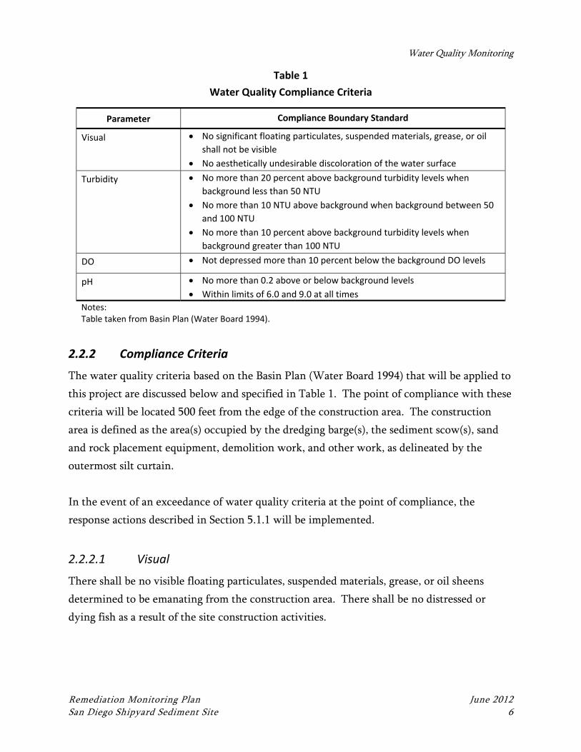
Water Quality Monitoring
Remediation Monitoring Plan June 2012 San Diego Shipyard Sediment Site 6
Table 1
Water Quality Compliance Criteria
Parameter Compliance Boundary Standard
Visual No significant floating particulates, suspended materials, grease, or oil
shall not be visible
No aesthetically undesirable discoloration of the water surface
Turbidity No more than 20 percent above background turbidity levels when
background less than 50 NTU
No more than 10 NTU above background when background between 50
and 100 NTU
No more than 10 percent above background turbidity levels when
background greater than 100 NTU
DO Not depressed more than 10 percent below the background DO levels
pH No more than 0.2 above or below background levels
Within limits of 6.0 and 9.0 at all times
Notes: Table taken from Basin Plan (Water Board 1994).
2.2.2 Compliance Criteria
The water quality criteria based on the Basin Plan (Water Board 1994) that will be applied to
this project are discussed below and specified in Table 1. The point of compliance with these
criteria will be located 500 feet from the edge of the construction area. The construction
area is defined as the area(s) occupied by the dredging barge(s), the sediment scow(s), sand
and rock placement equipment, demolition work, and other work, as delineated by the
outermost silt curtain.
In the event of an exceedance of water quality criteria at the point of compliance, the
response actions described in Section 5.1.1 will be implemented.
2.2.2.1 Visual
There shall be no visible floating particulates, suspended materials, grease, or oil sheens
determined to be emanating from the construction area. There shall be no distressed or
dying fish as a result of the site construction activities.
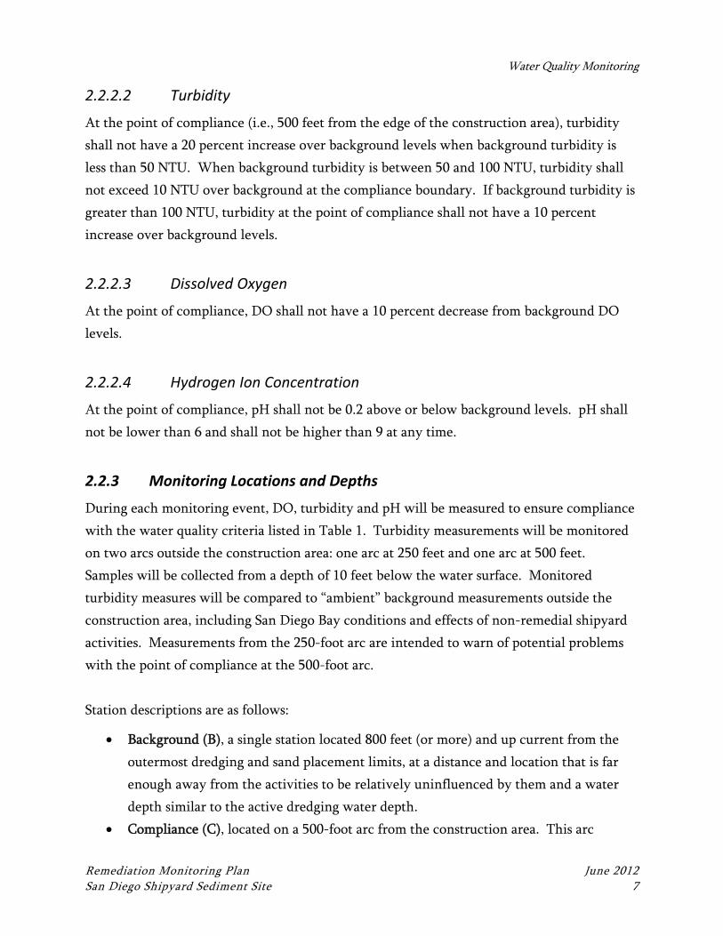
Water Quality Monitoring
Remediation Monitoring Plan June 2012 San Diego Shipyard Sediment Site 7
2.2.2.2 Turbidity
At the point of compliance (i.e., 500 feet from the edge of the construction area), turbidity
shall not have a 20 percent increase over background levels when background turbidity is
less than 50 NTU. When background turbidity is between 50 and 100 NTU, turbidity shall
not exceed 10 NTU over background at the compliance boundary. If background turbidity is
greater than 100 NTU, turbidity at the point of compliance shall not have a 10 percent
increase over background levels.
2.2.2.3 Dissolved Oxygen
At the point of compliance, DO shall not have a 10 percent decrease from background DO
levels.
2.2.2.4 Hydrogen Ion Concentration
At the point of compliance, pH shall not be 0.2 above or below background levels. pH shall
not be lower than 6 and shall not be higher than 9 at any time.
2.2.3 Monitoring Locations and Depths
During each monitoring event, DO, turbidity and pH will be measured to ensure compliance
with the water quality criteria listed in Table 1. Turbidity measurements will be monitored
on two arcs outside the construction area: one arc at 250 feet and one arc at 500 feet.
Samples will be collected from a depth of 10 feet below the water surface. Monitored
turbidity measures will be compared to “ambient” background measurements outside the
construction area, including San Diego Bay conditions and effects of non-remedial shipyard
activities. Measurements from the 250-foot arc are intended to warn of potential problems
with the point of compliance at the 500-foot arc.
Station descriptions are as follows:
Background (B), a single station located 800 feet (or more) and up current from the
outermost dredging and sand placement limits, at a distance and location that is far
enough away from the activities to be relatively uninfluenced by them and a water
depth similar to the active dredging water depth.
Compliance (C), located on a 500-foot arc from the construction area. This arc
Water Quality Monitoring
Remediation Monitoring Plan June 2012 San Diego Shipyard Sediment Site 8
defines the site compliance zone boundary.
Early Warning (E), located on a 250-foot arc from the construction area. This arc is
an additional “early warning” boundary.
Water quality will be monitored 10 feet below the surface at each of the stations.
2.2.4 Field Procedures
2.2.4.1 Methods and Equipment
Conventional parameters (turbidity, DO, and pH) will be measured using real-time,
calibrated automated field equipment (hydroprobe or equivalent) deployed to the
appropriate depth in the water column.
2.2.4.2 Sample Location and Depth Control
A laser range finder and/or differential global positioning system (DGPS) will be used to
locate and establish station locations. Location control data will be documented on a water
quality monitoring form.
2.2.4.3 Station Identification
All stations will be properly identified on the water quality monitoring form, and
consistently applied from one monitoring event to the next. Station names will use the
following identification scheme consisting of four alphanumeric characters:
A-B-C-
Where:
A The first character defines the monitoring station number.
B The second character will be used to identify the construction activity being
monitored:
D = dredging
P = material placement
C The next character will be used to identify the water quality monitoring location:
B = background station
Water Quality Monitoring
Remediation Monitoring Plan June 2012 San Diego Shipyard Sediment Site 9
E = early warning station
C = compliance station, bank (along the right river bank)
2.2.4.4 Field Documentation
Water quality measurement data that is automatically recorded will include date, time,
turbidity, pH, and DO measurements.
Documentation of visual water quality monitoring will include the following:
Location of observations
Date and time
Relevant description of observation(s)
Tidal phase (flood, ebb, slack)
Predominant direction of current
Weather and wind conditions
Any instances of apparent water quality exceedances or alarms will be brought to the
attention of the Project Coordinator.
2.2.4.5 Equipment Calibration and Maintenance
Monitoring equipment will undergo routine and ongoing calibration according to the
manufacturers’ instructions prior to use in the field. The automated monitoring system with
occasional manual measurements may be augmented by trained personnel if needed to
ensure accuracy of the monitoring system and/or to confirm specific measurements.
Instruments and equipment will be tested and inspected before each monitoring event. Any
field equipment that is faulty or not functioning properly will not be used for monitoring.
2.2.5 Monitoring Personnel and Responsibilities
Key monitoring personnel required to implement this WQMP include the following:
Water Quality Field Leader
Monitoring personnel
Water Quality Monitoring
Remediation Monitoring Plan June 2012 San Diego Shipyard Sediment Site 10
Persons fulfilling these roles will be designated at least 1 week prior to the start of
monitoring activities, and contact information will be provided at that time to the Water
Board and the Project Team. All monitoring personnel will be experienced in the collection
and measurement of water quality parameters.
2.2.5.1 Project Team Responsibilities
The Project Team will be responsible for:
Reviewing field reports to verify that appropriate field methods and quality control
procedures are being implemented in accordance with the procedures specified in this
WQMP
Coordinating with the contractor to ensure appropriate construction BMPs are being
implemented, and to strategize ways to add BMPs or enhance the effectiveness of
existing BMPs as necessary to mitigate unacceptable water quality effects
Submission of records to regulatory agencies as required by permits
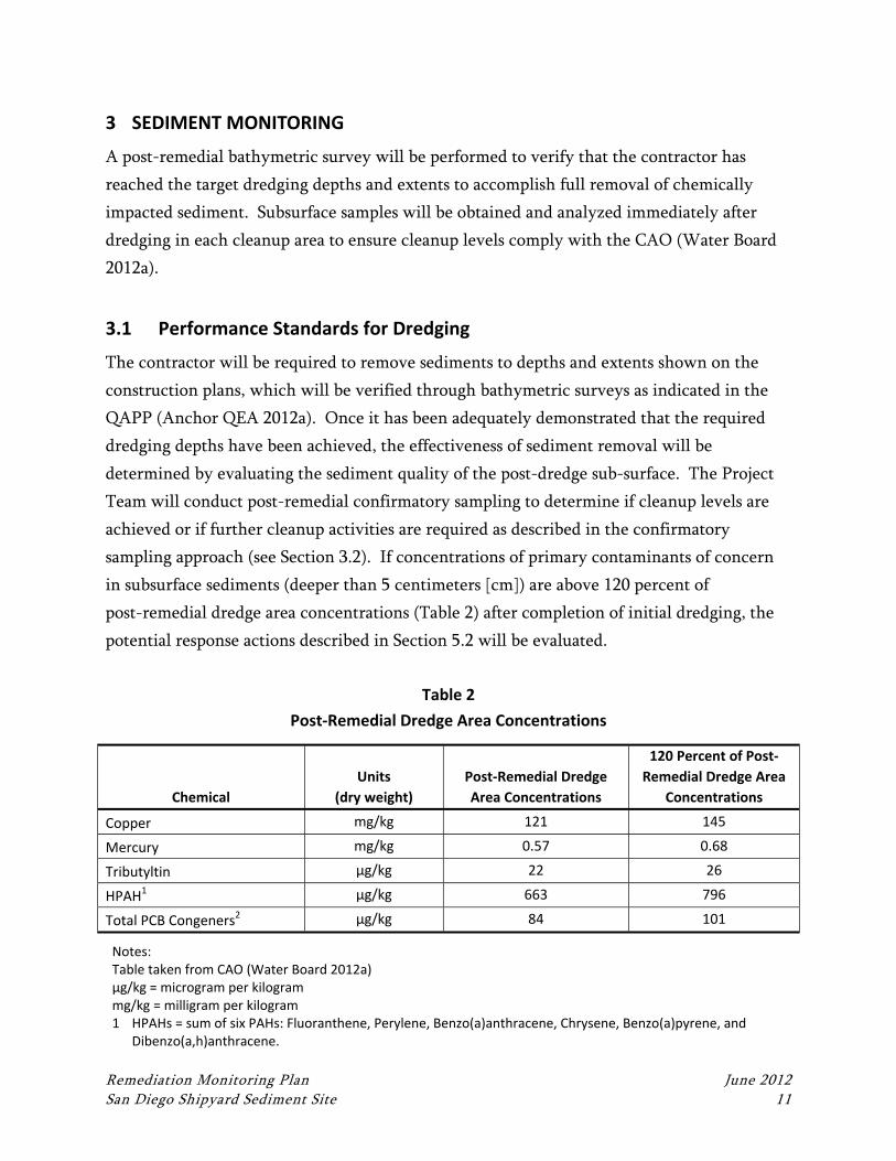
Remediation Monitoring Plan June 2012 San Diego Shipyard Sediment Site 11
3 SEDIMENT MONITORING
A post-remedial bathymetric survey will be performed to verify that the contractor has
reached the target dredging depths and extents to accomplish full removal of chemically
impacted sediment. Subsurface samples will be obtained and analyzed immediately after
dredging in each cleanup area to ensure cleanup levels comply with the CAO (Water Board
2012a).
3.1 Performance Standards for Dredging
The contractor will be required to remove sediments to depths and extents shown on the
construction plans, which will be verified through bathymetric surveys as indicated in the
QAPP (Anchor QEA 2012a). Once it has been adequately demonstrated that the required
dredging depths have been achieved, the effectiveness of sediment removal will be
determined by evaluating the sediment quality of the post-dredge sub-surface. The Project
Team will conduct post-remedial confirmatory sampling to determine if cleanup levels are
achieved or if further cleanup activities are required as described in the confirmatory
sampling approach (see Section 3.2). If concentrations of primary contaminants of concern
in subsurface sediments (deeper than 5 centimeters [cm]) are above 120 percent of
post-remedial dredge area concentrations (Table 2) after completion of initial dredging, the
potential response actions described in Section 5.2 will be evaluated.
Table 2
Post‐Remedial Dredge Area Concentrations
Chemical
Units
(dry weight)
Post‐Remedial Dredge
Area Concentrations
120 Percent of Post‐
Remedial Dredge Area
Concentrations
Copper mg/kg 121 145
Mercury mg/kg 0.57 0.68
Tributyltin µg/kg 22 26
HPAH1 µg/kg 663 796
Total PCB Congeners2 µg/kg 84 101
Notes: Table taken from CAO (Water Board 2012a) µg/kg = microgram per kilogram mg/kg = milligram per kilogram 1 HPAHs = sum of six PAHs: Fluoranthene, Perylene, Benzo(a)anthracene, Chrysene, Benzo(a)pyrene, and
Dibenzo(a,h)anthracene.
Sediment Monitoring
Remediation Monitoring Plan June 2012 San Diego Shipyard Sediment Site 12
2 Total PCBs = sum of 41 congeners: 18, 28, 37, 44, 49, 52, 66, 70, 74, 77, 81, 87, 99, 101, 105, 110, 114, 118, 119, 123, 126, 128, 138, 149, 151, 153, 156, 157, 158, 167, 168, 169, 170, 177, 180, 183, 187, 189, 194, 201, and 206.
3.2 Confirmation Sampling Objectives and Approach
The objective of confirmation sediment monitoring is to determine if cleanup activities have
met the cleanup objectives prior to the demobilization of the construction operation.
Estimates of sediment conditions will be established using average chemical concentrations
within the remedial footprint.
As is the case for any dredging project, a thin surface layer of unconsolidated (residual)
sediment is anticipated to remain in place after dredging has been completed. This can may
lead to the continued presence of near-surface chemical exceedances after dredging. In
addition, it is also possible that contamination will extend to depths greater than were
originally anticipated during the pre-design process. In either case, concentrations in post-
dredge confirmational subsurface samples could require further dredging or placement of a
clean sand cover. Section 5.3 summarizes the potential outcomes from the confirmational
samples and the actions or non-actions for each outcome.
To determine if the cleanup goals have been obtained, sediment cores will be collected
within the removal area. A sediment coring device will be used to obtain a surficial sample
(0 to 5 cm) and a subsurface composite sample (5 to as much as 60 cm). The surficial sample
(0 to 5 cm) will likely be comprised entirely of residual sediment material that was re-
deposited by the dredging process. (The thickness of residual deposits after dredging can be
up to several inches thick.) The subsurface samples, therefore, are important, because they
will extend beyond the residual layer into the underlying, undredged materials, and
therefore will be more representative of actual post-dredging bottom conditions.
3.3 Methods, Locations, and Timing
A brief summary of the monitoring methods, locations, and timing is provided in the
following subsections. Detailed procedures for subsurface and surface sediment sampling are
provided in the Sampling Analysis Plan (Anchor QEA 2012b) for this work. Detailed field
and laboratory quality assurance and quality control criteria, including method
Sediment Monitoring
Remediation Monitoring Plan June 2012 San Diego Shipyard Sediment Site 13
specifications, detection limits, accuracy and precision requirements, are provided in the
Post-Remedial Monitoring Plan [Exponent 2012]).
3.3.1 Sediment Sampling Methods
The confirmation subsurface sediment samples will be collected using a vibracore coring
device or similar deployed from a winch line on a sampling vessel. Cores will be advanced
up to 60 centimeters, or until refusal.
3.3.2 Sediment Sample Locations
Subsurface sediment sample locations will be systematically distributed to confirm
performance objectives have been achieved in each cleanup area. The horizontal extents of
the final cleanup areas will be determined during final design as described in the RAP and
Design Criteria Report (Anchor QEA 2012c and 2012d, respectively). Once cleanup areas
have been established, confirmation sediment sample locations will be designated.
3.3.3 Chemical Analytical Parameters
The subsurface depth horizon (5 to 60 cm) samples will be analyzed for and compared to the
post-remedial dredge area concentrations provided in Table 2. Aliquots from the 0 to 5 cm
interval will be archived. Consistent with the post-remedial program requirements and best
dredge practices, these samples may be used to determine the need for a clean sand cover.
3.3.4 Monitoring Timing
All confirmational sampling is estimated to occur within 24 to 48 hours after dredging has
been completed within each cleanup area. This timeframe is needed to allow dredge
residuals (sediment suspended during dredging) sufficient time to settle and, should
additional remedial activities be required, ensure that the test results are received prior to the
contractor demobilizing from the Shipyard Sediment Site.
Remediation Monitoring Plan June 2012 San Diego Shipyard Sediment Site 14
4 BIOLOGICAL MONITORING
As required by MMRP (Water Board 2012b) mitigation measures, the following biological
monitoring measures will be implemented:
A pre- and post-remedial eelgrass survey will be performed per Southern California
Eelgrass Mitigation Policy; if impacts are noted, mitigation measures will be
implemented in accordance with resource agency requirements.
Eelgrass beds will be identified and marked prior to construction by a biologist to
protect sea turtles.
Measures (e.g., speed restrictions, off-limit areas) will be implemented on
construction equipment and operations to ensure eelgrass beds are not impacted as a
result of the construction activities
Construction activities will be temporarily stopped if a sea turtle or marine mammal is
sighted within 100 meters of the construction area
In addition, the project specifications are expected to limit construction activities such that
they are performed only during the open environmental windows for least tern, so
Endangered Species Act monitoring is not anticipated to be required. If construction
activities extend into the least tern window, the appropriate ESA monitoring requirements
per the EIR (Water Board 2012b) will be implemented.
Remediation Monitoring Plan June 2012 San Diego Shipyard Sediment Site 15
5 POTENTIAL RESPONSE ACTIONS
5.1 Water Quality Monitoring
5.1.1 Exceedances of Water Quality Criteria
This section describes the contingency actions that will occur if the monitoring crew reports
an exceedance of a visual or conventional water quality parameter. In the event of an
exceedance, the contractor shall immediately notify the Project Team and begin to
implement additional or enhanced operational or engineering BMPs. The QAPP (Anchor
QEA 2012a) provides a standard list of construction BMPs to protect water quality.
Additional operational modifications are provided below.
5.1.1.1 Response(s) to Visual Monitoring
If visual monitoring indicates potential exceedance of water quality criteria during the
removal action (i.e., visible turbidity attributed to site construction activities), preventative
and/or corrective actions will be implemented described below will be followed.
5.1.1.2 Exceedance of Conventional Parameters
If conventional parameters (turbidity, DO, and/or pH) are exceeded at the compliance
boundary during removal action construction activities, the following contingency actions
will be implemented:
1. Evaluate the concurrent measurements at Background and Compliance monitoring
stations, and supporting visual evidence, to determine whether the exceedance is
caused by site construction activities versus other ambient conditions in the Bay (e.g.,
wind waves, boat wakes, barge/ship traffic, and storm inflow).
2. If the exceedance is confirmed, immediately notify the contractor and the Project
Team. The contractor will be directed to immediately modify operations or
implement additional BMPs to mitigate the exceedance (see QAPP for list of
construction BMPs to protect water quality and this Section for a list of additional
modifications to operations).
3. Reevaluate field measurements at all relevant stations 30 minutes later, after
additional BMPs or operational modifications are implemented.
4. The contractor shall take actions to mitigate the exceedance. If the water quality
exceedance continues to persist, even with additional BMPs or operational
Potential Response Actions
Remediation Monitoring Plan June 2012 San Diego Shipyard Sediment Site 16
modifications, a path forward will be discussed with the Project Team. The path
forward could include some or all of the following:
Implement more aggressive BMPs or operational modifications
If additional measures are not successful at controlling the water quality
exceedance, it may be necessary to stop work to further assess the source of
the exceedance, identify effective mitigation measures, and allow the water
column to recover.
5.1.1.3 Operational Modifications
In addition to the standard BMPs listed in the QAPP, the following operational
modifications can be implemented individually or in combination as part of the response to a
confirmed water quality exceedance:
Adjust the sequence and/or speed of dredging and disposal operations.
Reposition dredge operations in such a way as to ensure future exceedances do not
occur.
Fix, maintain, and/or upgrade floating silt curtains.
Modify, either on a temporary or permanent basis, dredge equipment (such as the
dredging bucket size or type).
5.1.2 Discharge of Oil, Fuel, or Chemicals
In the event of a discharge of oil, fuel, or chemicals into the Bay, the source of the spill or
leak shall be identified and controlled, and cleanup efforts shall begin immediately. The
contractor shall immediately notify Shipyard Sediment Site emergency response personnel,
who will make all appropriate regulatory notifications in accordance with Site emergency
notification procedures. Cleanup shall include appropriate disposal of any spilled material
and cleanup material.
5.2 Sediment Monitoring
A decision matrix for interpreting the results of the confirmation subsurface sediment
monitoring is provided in Table 3. The threshold for additional action (including additional
sampling, additional dredging, clean sand placement etc.) is an average subsurface (5 to 60
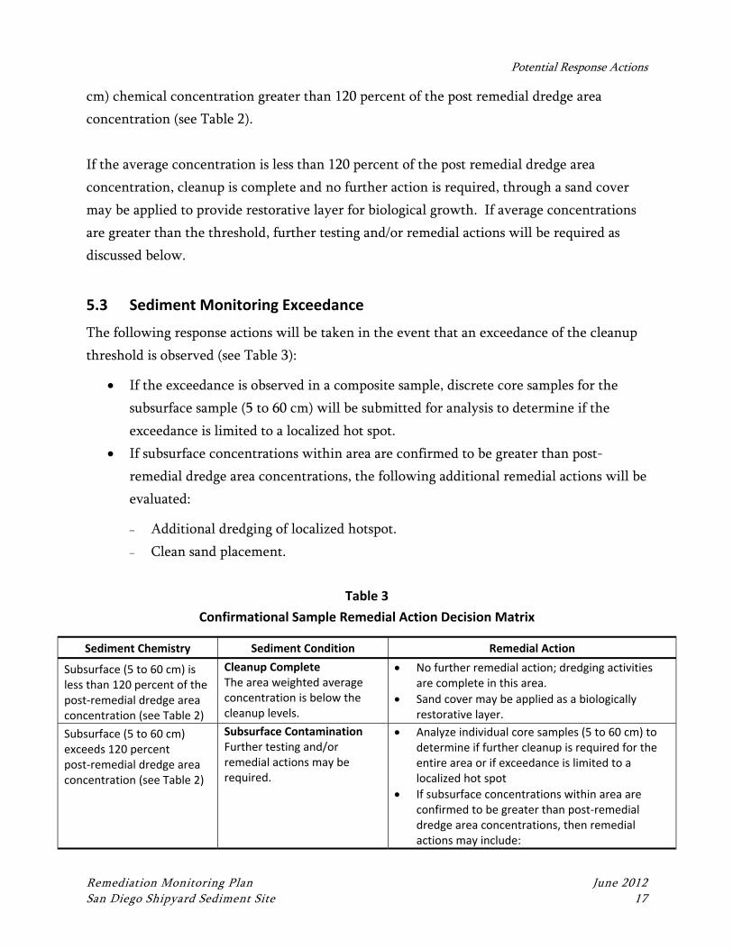
Potential Response Actions
Remediation Monitoring Plan June 2012 San Diego Shipyard Sediment Site 17
cm) chemical concentration greater than 120 percent of the post remedial dredge area
concentration (see Table 2).
If the average concentration is less than 120 percent of the post remedial dredge area
concentration, cleanup is complete and no further action is required, through a sand cover
may be applied to provide restorative layer for biological growth. If average concentrations
are greater than the threshold, further testing and/or remedial actions will be required as
discussed below.
5.3 Sediment Monitoring Exceedance
The following response actions will be taken in the event that an exceedance of the cleanup
threshold is observed (see Table 3):
If the exceedance is observed in a composite sample, discrete core samples for the
subsurface sample (5 to 60 cm) will be submitted for analysis to determine if the
exceedance is limited to a localized hot spot.
If subsurface concentrations within area are confirmed to be greater than post-
remedial dredge area concentrations, the following additional remedial actions will be
evaluated:
Additional dredging of localized hotspot.
Clean sand placement.
Table 3
Confirmational Sample Remedial Action Decision Matrix
Sediment Chemistry Sediment Condition Remedial Action
Subsurface (5 to 60 cm) is less than 120 percent of the post‐remedial dredge area concentration (see Table 2)
Cleanup CompleteThe area weighted average concentration is below the cleanup levels.
No further remedial action; dredging activities are complete in this area.
Sand cover may be applied as a biologically restorative layer.
Subsurface (5 to 60 cm) exceeds 120 percent post‐remedial dredge area concentration (see Table 2)
Subsurface ContaminationFurther testing and/or remedial actions may be required.
Analyze individual core samples (5 to 60 cm) to determine if further cleanup is required for the entire area or if exceedance is limited to a localized hot spot
If subsurface concentrations within area are confirmed to be greater than post‐remedial dredge area concentrations, then remedial actions may include:
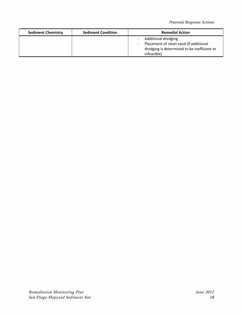
Potential Response Actions
Remediation Monitoring Plan June 2012 San Diego Shipyard Sediment Site 18
Sediment Chemistry Sediment Condition Remedial Action
Additional dredging Placement of clean sand (if additional
dredging is determined to be inefficient or infeasible)
Remediation Monitoring Plan June 2012 San Diego Shipyard Sediment Site 19
6 REPORTING
6.1 Weekly Reports
As required by the MMRP (Water Board 2012b), the Project Team will prepare and submit
weekly water quality monitoring reports, which provide results from each week’s water
quality monitoring activities and will compile the results into a summary table with a
comparison to water quality compliance criteria.
6.2 Quarterly Reports
As required by the CAO (Water Board 2012a), the Project Team will prepare and submit
quarterly progress reports, which describe all actions taken toward achieving compliance
with the CAO, as well as results of any sampling, testing, analyses, data collection, or other
evaluations. Quarterly reports will be submitted by or before the 15th of March, June,
September, and December of each year following the CAO’s effective date. Each quarterly
report will summarize current schedule and any delays or modifications to that schedule.
Remediation Monitoring Plan June 2012 San Diego Shipyard Sediment Site 20
7 REFERENCES
Anchor QEA, L.P., 2012a. Quality Assurance Project Plan for the San Diego Shipyard
Sediment Site. June 2012.
Anchor QEA, 2012b. Sampling and Analysis Plan for the San Diego Shipyard Sediment Site.
June 2012.
Anchor QEA, 2012c. Remedial Action Plan for the San Diego Shipyard Sediment Site. June
2012.
Anchor QEA, 2012d. Design Criteria Report for the San Diego Shipyard Sediment Site. June
2012.
Exponent, 2012. Post-Remediation Monitoring Plan, San Diego Shipyard Sediment Site.
Prepared for the Regional Water Quality Control Board. June 2012.
SWRCB (State Water Resources Control Board), 2005. Ocean Plan: Water Quality Control
Plan Ocean Waters of California.
Water Board (Regional Water Quality Control Board), 1994. Water Quality Control Plan for
San Diego Basin. California Regional Water Quality Control Board, Region 9, San
Diego, California.
Water Board, 2012a. Cleanup and Abatement Order No. R9-2012-0024 for the Shipyard
Sediment Site. March 14, 2012.
Water Board 2012b. Final Environmental Impact Report. March 14, 2012.
SAMPLING AND ANALYSIS PLAN
SAN DIEGO SHIPYARD SEDIMENT SITE
Cleanup and Abatement Order No. R9‐2012‐0024
Prepared by
Anchor QEA, L.P.
26300 La Alameda, Suite 240
Mission Viejo, California 92691
June 12, 2012
Sampling and Analysis Plan June 2012 San Diego Shipyard Sediment Site i
TABLE OF CONTENTS
1 INTRODUCTION .................................................................................................................. 1
2 GENERAL FIELD OPERATIONS ......................................................................................... 3
2.1 Station Positioning ...........................................................................................................3
2.1.1 Differential Global Positioning System .....................................................................4
2.1.2 Visual Horizontal Triangulation Methods ................................................................4
2.1.3 Vertical Control ..........................................................................................................4
2.2 Equipment List .................................................................................................................4
2.3 Decontamination Procedures ..........................................................................................5
2.4 Sample Identification .......................................................................................................5
3 COLLECTION METHODS, PROCEDURES, AND SCHEDULE .......................................... 7
3.1 Subsurface Sediment Collection ......................................................................................7
3.1.1 Sampling Contractor ..................................................................................................7
3.1.2 Sampling Methods ......................................................................................................7
3.1.2.1 Sediment Coring Procedures ........................................................................... 7
3.1.2.2 Sample Acceptance Criteria ............................................................................. 8
3.1.3 Sample Processing ......................................................................................................8
3.1.3.1 Core Logging ..................................................................................................... 9
3.1.3.2 Subsampling and Compositing ......................................................................... 9
3.1.4 Sample Collection Schedule .....................................................................................10
4 DOCUMENTATION, SAMPLE HANDLING, AND CHAIN-OF-CUSTODY ................... 11
4.1 Documentation ...............................................................................................................11
4.1.1 Documentation Entries ............................................................................................12
4.1.2 Specific Requirements ..............................................................................................12
4.1.2.1 Sample Collection ........................................................................................... 12
4.1.2.2 Sample Labeling .............................................................................................. 13
4.2 Sample Handling ............................................................................................................13
4.3 Chain-of-Custody ...........................................................................................................14
5 QUALITY ASSURANCE AND QUALITY CONTROL REQUIREMENTS ........................ 16
5.1 Analytical Chemistry .....................................................................................................16
6 WASTE MANAGEMENT PLAN ......................................................................................... 17
Table of Contents
Sampling and Analysis Plan June 2012 San Diego Shipyard Sediment Site ii
7 REFERENCES ...................................................................................................................... 18
List of Figures
Figure 1 Site Map .................................................................................................................. 2
Sampling and Analysis Plan June 2012 San Diego Shipyard Sediment Site iii
LIST OF ACRONYMS AND ABBREVIATIONS
°C degree Celsius
CAO Cleanup and Abatement Order
COC chain-of-custody
COPC chemical of potential concern
CRP Community Relations Plan
DCR Design Criteria Report
DGPS digital global position system
HASP Health and Safety Plan
NAD83 North American Datum 1983
MLLW mean lower low water
PPE personal protection equipment
QA quality assurance
QAPP Quality Assurance Project Plan
QC quality control
RAP Remedial Action Plan
RMP Remedial Monitoring Plan
SAP Sampling and Analysis Plan
Shipyard Sediment Site San Diego Shipyard Sediment Site
Sampling and Analysis Plan June 2012 San Diego Shipyard Sediment Site 1
1 INTRODUCTION
In March 2012, the San Diego Regional Water Quality Control Board (Water Board) issued
Cleanup and Abatement Order (CAO) No. R9-2012-0024 for the remediation of marine
sediments containing elevated chemical concentrations within the San Diego Shipyard
Sediment Site (Shipyard Sediment Site) in San Diego, California (Water Board 2012). From
the early 1900s through February 1963, the City of San Diego was the trustee of all relevant
portions of the San Diego Bay tidelands, which include the Shipyard Sediment Site, and
leased the tidelands to various operators. By act of legislature in 1962, the San Diego Unified
Port District was created and in 1963 became the Trustee to the tidelands. The Shipyard
Sediment Site includes the waters adjacent to two adjoining, active shipyard facilities in San
Diego Bay—the North Shipyard (owned BAE Systems San Diego Ship Repair Facility) and
the South Shipyard (owned National Steel and Shipbuilding Company Shipyard Facility).
Figure 1 depicts the location of the Shipyard Sediment Site and the layout of the North and
South Shipyard Areas. The Shipyard Sediment Site remedial footprint extends from the U.S.
Bulkhead Line (shoreline) to San Diego Bay’s main shipping channel to the west.
This Sampling and Analysis Plan (SAP) is one component of the Remedial Action Plan (RAP)
for the Shipyards Sediment Site. This document describes detailed methodologies for
sediment sampling as required for pre-design field investigations and confirmation of
dredging completion. In particular, this SAP addresses the following:
Subsurface sediment sampling for chemicals of potential concern (COPCs)
Decontamination procedures
Sample identification procedures
Sample collection schedule
Sampling documentation, sample handling, and chain-of-custody procedures
Quality assurance and quality control (QA/QC) requirements
Waste management

SDG&EParcel
Figure 1Site Map
San Diego Shipyard Sediment Site
Q:\Job
s\0201
96-01
_BAE
_Syste
ms\M
aps\RA
P\Loca
ton_M
ap.mx
d nko
chie 6/
12/201
2 12:
55:14
PM
0 200 400 600 800Feet
[
! ! Shipyard Leasehold LineShipyard Sediment Site
§̈¦5 §̈¦805
§̈¦8§̈¦15
§̈¦15
Pacific OceanPacific Ocean
San Diego Bay
San Diego Bay
Chula Vista
National City
CoronadoBonita
San Diego
Buildin
g Ways
4 Buildin
g Ways
3On B
lock
Building
Dock 1Be
rth W
all
Berth I
Berth
III
Berth
IV
Berth
V
Berth
VI
Berth VII
Berth
IXBerth
X
Pier 3
City Outfall
Pier 2
Pier 1
Extent of Shipyard Sediment Site
ShipyardSediment
Site
NORTHSHIPYARD
AREA(SEE FIGURE 2)
SOUTHSHIPYARD
AREA(SEE FIGURE 3)
North Shipyard Leasehold LineSouth Shipyard Leasehold Line
San DiegoCoronado
National City
Chula Vista
Bonita
Sampling and Analysis Plan June 2012 San Diego Shipyard Sediment Site 3
2 GENERAL FIELD OPERATIONS
This section describes the sediment sample collection activities as they pertain to the
Remedial Monitoring Plan (RMP; Anchor QEA 2012a). Methods for water quality
measurement are described in detail in the RMP and are not included in this SAP. As
indicated in the Quality Assurance Project Plan (QAPP; Anchor QEA 2012b), import
material testing and disposal monitoring will be performed by the contractor and are also not
included in this SAP.
Subsurface sediment sampling will be conducted to inform design activities and to confirm
remedial actions have achieved the remediation goals outlined in the RAP and to inform
additional removal action if necessary. The remainder of this section provides information
that is consistent for all sediment sampling methods, including station positioning,
equipment, and laboratory analytical parameters. The following sections provide method-
specific collection and processing procedures.
2.1 Station Positioning
The objective of location control is to accurately determine horizontal and vertical
positioning of sampling locations. To achieve this objective, each sample location will be
referenced to known survey control points using the methods described below.
The following parameters will be documented at each sampling location, if applicable:
Location coordinates (California state plane, north zone, North American Datum 1983
[NAD83], international survey feet)
Vertical elevation in feet National Geodetic Vertical Datum (mean lower low water
[MLLW], including mudline and tidal elevation above mudline)
Actual water depth
Time and date
Tidal elevation referenced to MLLW
These parameters will be measured using a differential global positioning system (DGPS),
pre-surveyed, visual horizontal triangulation to known control points and/or landmarks on
shore if necessary, and vertical control using weighted tape measures.
General Field Operations
Sampling and Analysis Plan June 2012 San Diego Shipyard Sediment Site 4
2.1.1 Differential Global Positioning System
Location control will be performed with a DGPS unit onboard the sampling vessel. DGPS
coordinates for each sampling location will be recorded at the time of sampling.
2.1.2 Visual Horizontal Triangulation Methods
Visual horizontal triangulation methods will be used as a backup method to the DGPS. This
system will use pre-surveyed markers and/or established landmarks on shore. This method
determines sampling locations based on horizontal distances to survey control points and/or
landmarks identifiable on base maps. Locations will be identified by measuring the
horizontal distance from the actual sampling location to the known control point or
landmark to the nearest foot using a tape measure. Horizontal measurements can be
calculated from registered base maps so field measurements can be translated to state plane
coordinates. Buoy markers may be used to mark the sampling location.
2.1.3 Vertical Control
The vertical control parameters measured will be depth to sediment (mudline) and tidal
elevation. The depth to sediment will be measured during each sampling event using a
hand-held weighted tape (lead line). The tape will be dropped from the work platform to
the bottom, pulled taut, and read to the nearest 0.1 foot. This observation will be cross-
checked against the onboard depth sounder.
Tidal readings will be taken periodically from a tide board installed on site and checked
against daily tide charts for San Diego Bay. Tidal elevations and time will be monitored and
recorded before each sample is collected to the nearest 0.1 foot. Sample elevations will then
be corrected to MLLW.
2.2 Equipment List
The following general equipment will be required during sample collection procedures:
Personal protective equipment (PPE), as required by the Health and Safety Plan
(HASP; Anchor QEA 2012c)
Navigation and site maps
Camera
General Field Operations
Sampling and Analysis Plan June 2012 San Diego Shipyard Sediment Site 5
Field notebook
Aluminum decked boat equipped with outboard motor
Calibrated rod or ruler for sediment depth measurement
Sampling device (vibracore sampler or similar device)
Weighted tape measure calibrated in 0.1-foot increments
Decontamination supplies
2.3 Decontamination Procedures
Sample containers, instruments, working surfaces, technician protective gear, and other
items that may come into contact with collected samples must meet high standards of
cleanliness. All equipment that comes into contact with sampling media will be
decontaminated prior to each day’s use and between sampling locations. The
decontamination procedure is as follows:
Pre-wash rinse with site water
Wash with solution of laboratory grade non-phosphate-based soap
Rinse with site water
Rinse three times with laboratory-grade distilled water
Store in clean, closed container or wrap in aluminum foil for next use
Additionally, the laboratory will provide pre-cleaned and labeled sample containers.
2.4 Sample Identification
All sediment samples will be properly identified on their attached labels as well as in any
forms or other documentation. All sample identifications will be consistent with the
following identification scheme:
The first two characters will be “SD” to identify the samples as Shipyard Sediment
Site samples.
The next character will be used to designate North Shipyard (“N”) or South Shipyard
(“S”) area samples.
The next character will identify whether the sample has been obtained for pre-design
purposes (“P”) or for post-dredge confirmatory purposes (“C”).
The next characters will identify the station location. Station location names will be
General Field Operations
Sampling and Analysis Plan June 2012 San Diego Shipyard Sediment Site 6
determined during final design.
The next character will indicate the whether the sediment sample is discrete (“D”) or
composite (“C”)
The next four characters will indicate the depth interval (in centimeters) of the
sample:
0005 (0 to 5 cm)
0560 (5 to 60 cm)
Or otherwise, per this numbering protocol
The last six characters will indicate the sample date by YYMMDD.
For example, following this identification scheme, SD-N-C-[Station ID]-D-0560-120607
indicates a discrete confirmatory sediment sample of the 5 to 60 cm interval collected at the
North Shipyard Area on June 7, 2012.
Sampling and Analysis Plan June 2012 San Diego Shipyard Sediment Site 7
3 COLLECTION METHODS, PROCEDURES, AND SCHEDULE
This section describes the sampling methods and procedures specific for collecting and
processing subsurface sediment samples.
3.1 Subsurface Sediment Collection
3.1.1 Sampling Contractor
Collection of sediment cores will be conducted using an experienced vibracore contractor.
3.1.2 Sampling Methods
Sediment cores will be collected using vibracoring methods. The Project Team will
coordinate vibracore sample collection, sediment compositing, and sample transport to the
analytical laboratory. Cores will be collected at the locations to be determined as part of the
final remedial design. Sediment core locations may be adjusted in the field as necessary if
difficult conditions are encountered such as refusal, poor recovery, underwater obstructions,
or vessel obstructions.
3.1.2.1 Sediment Coring Procedures
Sediment cores will be collected using a 3-inch or 4-inch vibracorer, or equivalent sampling
technology. The vibracorer is typically deployed using an A-frame and winch assembly.
The vibracorer will be lowered to the bottom, where the unit will be energized and
advanced to the appropriate depth. The target coring depth at all locations will be 60 cm
below the dredged surface. Cores will be driven to this target depth or to refusal. Target
core lengths will be a minimum of 60 cm.
If refusal is encountered at any core location, the core sample will be offset from 10 to 100
feet, and the station will be re-attempted at a comparable water depth. After three rejections
or refusals at a given station, the core will be processed using the available recovered
intervals. If field evidence suggests refusal is caused by dense or gravelly native alluvium, it
may be assumed that this material is below screening levels. If refusal at multiple locations
results in significant changes to the SAP, these changes will be discussed with the project
manager.
Collection Methods, Procedures, and Schedule
Sampling and Analysis Plan June 2012 San Diego Shipyard Sediment Site 8
Recovered core tubes will be cut into sections, capped, stored upright (vertical) onboard the
vessel, and sent to the logging and processing site at the end of the day or periodically
throughout the day. The core tubes will be individually labeled with core orientation clearly
marked. Labels identifying the core section will be etched into the tube or securely attached
to the outside of the casing and wrapped with transparent tape to prevent loss or damage of
the label.
3.1.2.2 Sample Acceptance Criteria
Sample acceptance criteria are listed below. If acceptance criteria are not achieved, the core
will be rejected and another collection attempt will be made.
Following are the sediment core acceptance criteria:
The core penetrated to (and retained material to) the project depth or refusal.
Recovery was at least 75 percent of the length of core penetration.
Sediment does not extend out of the top of the core tube or contact any part of the
sampling apparatus at the top of the core tube.
There are no obstructions in the cored material that might have blocked the
subsequent entry of sediment into the core tube and resulted in incomplete core
collection.
There are no significant air gaps in the core tube or evidence of significant loss of
material out of the cutter head during retrieval.
3.1.3 Sample Processing
This section describes core processing procedures, including sample compositing procedures,
equipment decontamination, sample storage, and preservation requirements. Sediment
processing will likely be conducted at an onshore processing area at the San Diego Shipyard.
Core sections will be offloaded from the sampling vessel and transferred to the crew at the
onshore processing area. At the processing facility, cores will be opened, described, and
subsampled. Sediment samples will be homogenized, labeled, and dispatched under chain-
of-custody procedures (described in Section 4) to the analytical laboratory.
Collection Methods, Procedures, and Schedule
Sampling and Analysis Plan June 2012 San Diego Shipyard Sediment Site 9
3.1.3.1 Core Logging
Core tubes will be cut longitudinally using a clean carpet knife, reciprocating saw, or similar
device, taking care not to penetrate the sediment too deeply while cutting. Each core will be
described and documented on standardized core log forms. The core logs will include the
following observations, as relevant:
Sample recovery (recovered sediment depth relative to penetration depth) and
calculated percent compaction
Physical soil description in accordance with the Unified Soil Classification System
(includes soil type, density, color, etc.)
Odor (e.g., hydrogen sulfide, petroleum, etc.)
Presence of vegetation
Presence of man-made debris (e.g., trash)
Biological activity (e.g., shells, tubes, burrows, organisms, etc.)
Presence and depth of the redox layer, if observed
Depth and distinctness of geologic contacts
Any other distinguishing characteristics or features
3.1.3.2 Subsampling and Compositing
A final subsurface sediment subsampling and compositing scheme will be developed during
final design.
Each container will be clearly labeled with the following information:
Project name
Sample identification number
Type of analysis
Date and time
Initials of the person preparing the sample
This information will be recorded in the log book and on the chain-of-custody forms. Field
quality control samples will also be documented and identified in the field logs. Following
proper sealing and labeling, all sample containers will be placed on ice in a cooler and
maintained at 4 degrees plus or minus 2 degrees Celsius (°C) during storage and transport to
the analytical laboratory.
Collection Methods, Procedures, and Schedule
Sampling and Analysis Plan June 2012 San Diego Shipyard Sediment Site 10
3.1.4 Sample Collection Schedule
The schedule of sample collection events is identified in the RMP (Anchor QEA 2012a).
Sampling and Analysis Plan June 2012 San Diego Shipyard Sediment Site 11
4 DOCUMENTATION, SAMPLE HANDLING, AND CHAIN‐OF‐CUSTODY
The following sections outline the requirements for documentation, sample handling, and
chain-of-custody procedures related to the sample collection events.
4.1 Documentation
Field activities and samples must be properly documented during the sample collection
process. Documentation of field activities provides an accurate and comprehensive record of
the work performed sufficient for a technical peer to reconstruct the day's activities and
provide certification that all necessary requirements were met. General requirements
include:
Use of a field activity log to formally document activities and events. The field
activity log can be a standard or project-specific form or a bound field book.
Preprinted standard forms are available for many activities and should be used
whenever possible. These forms will provide prompts and request additional
information that may be useful and/or needed, and that the author is not aware of at
the time. Project-specific field forms may be generated or existing forms may be
modified to meet specific project needs. As required, client-supplied forms may be
substituted.
Appropriate header information documented on each page, including project title,
project number, date, weather conditions, changes in weather conditions, other
persons (if any) in the field party, and author. The specific information requested
depends on the nature of the work being performed and on the form being used.
Information fields that are not applicable should be noted "N/A" or with other
appropriate notations.
Field documentation entries using indelible ink.
Legible data entries. A single line should be drawn through incorrect entries and the
corrected entry should be written next to the original strikeout. Strikeouts are to be
initialed and dated by the originator.
Applicable units of measurement with entry values.
Field records maintained in project files unless otherwise specified by a client or
stipulated by a contract.
Documentation, Sample Handling, and Chain-of-Custody
Sampling and Analysis Plan June 2012 San Diego Shipyard Sediment Site 12
4.1.1 Documentation Entries
A chronology of field events will be recorded. General entry requirements include:
Visitors to the removal action area, including owner and regulatory representatives
Summary of pertinent project communications with the client, regulators, or other
removal action area visitors
Other contractors working at the removal action area
A description of the day's field activities, in chronological sequence using military
time notation (e.g., 9:00 am: 0900, and 5:00 pm: 1700)
If applicable, calibration of measuring and test equipment and identification of the
calibration standard(s) and use of a calibration log, if available, with cross-reference
entered into the field book
Field equipment identification, including type, manufacturer, model number, or other
specific information
General weather conditions, including temperature, wind speed, and direction
readings, including time of measurement and units
Safety and/or monitoring equipment readings, including time of measurements and
units
If applicable, reference in the field notebook to specific forms used for collection of
data
Subcontractor progress and/or problems encountered
Changes in the scope of work
Other unusual events
4.1.2 Specific Requirements
4.1.2.1 Sample Collection
Sample collection data will be documented in a bound field book and/or on a sample
collection form. Where both are being used, information contained in one is cross-
referenced to the other. Entries include:
Sample identification number, location taken, depth interval, sample media, sample
preservative, collection time, and date
Sample collection method and protocol
Physical description of the sample (standard classification system for soil)
Documentation, Sample Handling, and Chain-of-Custody
Sampling and Analysis Plan June 2012 San Diego Shipyard Sediment Site 13
If a composite sample, the sample’s make up, including number and location of
samples incorporated
Quality control-related samples collected (e.g., duplicates, blinds, trip blanks, field
blanks)
Container description and sample volume
Length and depth intervals of each core section and estimated recovery for each
sediment sample, as measured in MLLW
Pertinent technical comments
Location of each station, as determined by DGPS
Elevation of each station sampled, as measured in MLLW
Names of field supervisor and person(s) collecting and handling the sample
Observations made during sample collection, including weather conditions, currents
(if any), ship traffic, and other relevant field conditions
Descriptions of apparent resistance of sediment column to sampling (i.e., sediment
density and coring conditions)
Any deviation from the approved SAP
4.1.2.2 Sample Labeling
Sample labels must be prepared and attached to sample containers. Labels will either be
provided by the laboratory performing the analyses or will be generated internally. The
information to be provided includes:
Sample identification number
Sample date and collection time
Physical description of the sample (e.g., water, solid, gas)
Analytical parameters
Preservatives, if present
Sample location
Client
4.2 Sample Handling
Sample handling procedures include correctly labeling and packing all sample containers
prior to transport for laboratory testing. Sample containers will be obtained from the
Documentation, Sample Handling, and Chain-of-Custody
Sampling and Analysis Plan June 2012 San Diego Shipyard Sediment Site 14
analytical laboratory. Each container will be labeled appropriately with all relevant
information, including at a minimum:
Sample type
Project number and site name
Sample identification
Date
Time
Sampler’s initials
Samples will be stored and shipped in a properly packed container at 4°C. All samples will be
delivered to the laboratory as soon as possible after the time of collection to facilitate a fast
turnaround time.
4.3 Chain‐of‐Custody
An important component of data collection is the ability to demonstrate that the samples
were obtained from the stated locations and that they reached the laboratory or archive
without alteration. Evidence of collection, shipment, laboratory receipt, and laboratory
custody until disposal or archive must be properly documented. Documentation will be
accomplished through the use of a COC form that documents each sample and identifies the
individuals responsible for sample collection, shipment, and receipt. A sample is considered
in custody if at least one of the following criteria is met:
The sample is in a person's actual possession
The sample is in unobstructed view, after being in the person’s actual possession
The sample is locked and only accessible by the custodian after having been in the
person’s actual possession
The sample is in a secured area, restricted to authorized personnel (e.g., laboratory)
A laboratory typically will not accept samples for analysis without a correctly prepared COC
form. The COC form must be signed by each individual who has the sample in his or her
custody. A COC form is to be prepared for each sample shipped to a laboratory for analysis.
Information on this form correlates with other supporting documentation, including sample
labels and sample collection logs.
Documentation, Sample Handling, and Chain-of-Custody
Sampling and Analysis Plan June 2012 San Diego Shipyard Sediment Site 15
The COC form accounts for the elapsed time and custodians of the sample from the time of
its collection. The individuals who have physically handled the sample or witnessed initial
sample collection and packaging (e.g., a sample team member) must be identified on the
form. A sample team member relinquishes the sample by signing the COC form. Individuals
who either relinquish or receive samples must include their complete names, company
affiliation, and the date and time the samples were relinquished and received. The times that
the samples are relinquished and received by the next custodian should coincide, with the
exception of transfer by commercial carriers. Commercial carriers will not be required to
sign the COC form.
If a sample is to be stored for a period of time (e.g., overnight), measures are to be taken to
secure the sample container in a manner that provides only the custodian of record with
access. If samples are relinquished to a commercial carrier (e.g., UPS or Federal Express), the
carrier waybill number will be recorded and a copy of the waybill will be attached to the
COC form. The original COC form is sealed inside the shipping container with the samples.
Extra copies of all documents will be maintained with other field documentation.
If a correction is made to the COC form, the correction should be made by the originator of
the change, who will draw a single line through the error, initial and date the correction and,
if necessary, provide an explanation of the change. The documentation should have
sufficient detail to clearly document the change to a third-party reviewer.
Sampling and Analysis Plan June 2012 San Diego Shipyard Sediment Site 16
5 QUALITY ASSURANCE AND QUALITY CONTROL REQUIREMENTS
All analyses described in this SAP will be conducted in accordance with the standard QA/QC
procedures described in the Post-Remedial Work Plan (PRWP; Exponent 2012). Analytical
instruments will be maintained and calibrated regularly. Log books will be maintained for
major field and laboratory instrumentation to document servicing, maintenance, and
instrument modification.
5.1 Analytical Chemistry
Quality procedures are described for each analytical method in the PRWP. The type and
frequency of QA/QC samples analyzed by the laboratory will be according to the specified
analytical method. Necessary corrective actions will be taken to address problems, according
to the guidelines for a particular method. All corrective actions will be reported, along with
any deviations from the standard protocols.
Results of all laboratory QA/QC analyses and anything that might affect the integrity of the
results will be reported. Any deviations from the standard testing guidelines, QA/QC limits,
and acceptability criteria will be reported, including a discussion of their effect on data
validity. All data sheets will be checked to ensure that test conditions are within the
protocol specifications, and project data will be reviewed to determine their usability for
making suitability determinations.
Sampling and Analysis Plan June 2012 San Diego Shipyard Sediment Site 17
6 WASTE MANAGEMENT PLAN
This waste management plan presents the procedures that will be used to properly dispose of
field-generated waste from the field work associated with sediment grab samples. Waste in
the category of disposable sampling materials and PPE will be placed in heavy-weight
garbage bags or other appropriate containers.
All disposable sampling materials and PPE used in sample processing (e.g., disposable
coveralls, gloves, and tubing) will be placed in heavyweight garbage bags or other
appropriate containers. Disposable materials will be placed in an on-site refuse container for
disposal at a solid waste landfill.
Sampling and Analysis Plan June 2012 San Diego Shipyard Sediment Site 18
7 REFERENCES
Anchor QEA, L.P., 2012a. Remediation Monitoring Plan for the San Diego Shipyard
Sediment Site. June 2012.
Anchor QEA, 2012b. Quality Assurance Project Plan for the San Diego Shipyard Sediment
Site. June 2012.
Anchor QEA, 2012c. Health and Safety Plan for the San Diego Shipyard Sediment Site. June
2012.
Exponent, 2012. Post-Remediation Monitoring Plan, San Diego Shipyard Sediment Site.
Prepared for the Regional Water Quality Control Board. June 2012.
Water Board (San Diego Regional Water Quality Control Board), 2012a. Cleanup and
Abatement Order R9-2012-0024 for the Shipyard Sediment Site. March 14, 2012.

COMMUNITY RELATIONS PLAN
SAN DIEGO SHIPYARD SEDIMENT SITE
Cleanup and Abatement Order No. R9‐2012‐0043
Prepared by
Anchor QEA, L.P.
26300 La Alameda, Suite 240
Mission Viejo, California 92691
June 12, 2012
Community Relations Plan June 2012 San Diego Shipyard Sediment Site i
TABLE OF CONTENTS
1 INTRODUCTION .................................................................................................................. 1
2 PROJECT COMMUNICATION ............................................................................................ 4
List of Figures
Figure 1 Site Map .................................................................................................................. 2
Figure 2 Remediation Schedule ........................................................................................... 3
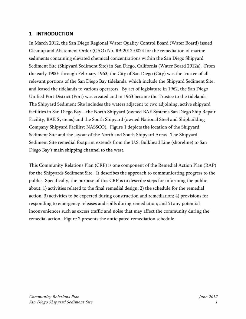
Community Relations Plan June 2012 San Diego Shipyard Sediment Site 1
1 INTRODUCTION
In March 2012, the San Diego Regional Water Quality Control Board (Water Board) issued
Cleanup and Abatement Order (CAO) No. R9-2012-0024 for the remediation of marine
sediments containing elevated chemical concentrations within the San Diego Shipyard
Sediment Site (Shipyard Sediment Site) in San Diego, California (Water Board 2012a). From
the early 1900s through February 1963, the City of San Diego (City) was the trustee of all
relevant portions of the San Diego Bay tidelands, which include the Shipyard Sediment Site,
and leased the tidelands to various operators. By act of legislature in 1962, the San Diego
Unified Port District (Port) was created and in 1963 became the Trustee to the tidelands.
The Shipyard Sediment Site includes the waters adjacent to two adjoining, active shipyard
facilities in San Diego Bay—the North Shipyard (owned BAE Systems San Diego Ship Repair
Facility; BAE Systems) and the South Shipyard (owned National Steel and Shipbuilding
Company Shipyard Facility; NASSCO). Figure 1 depicts the location of the Shipyard
Sediment Site and the layout of the North and South Shipyard Areas. The Shipyard
Sediment Site remedial footprint extends from the U.S. Bulkhead Line (shoreline) to San
Diego Bay’s main shipping channel to the west.
This Community Relations Plan (CRP) is one component of the Remedial Action Plan (RAP)
for the Shipyards Sediment Site. It describes the approach to communicating progress to the
public. Specifically, the purpose of this CRP is to describe steps for informing the public
about: 1) activities related to the final remedial design; 2) the schedule for the remedial
action; 3) activities to be expected during construction and remediation; 4) provisions for
responding to emergency releases and spills during remediation; and 5) any potential
inconveniences such as excess traffic and noise that may affect the community during the
remedial action. Figure 2 presents the anticipated remediation schedule.

SDG&EParcel
Figure 1Site Map
San Diego Shipyard Sediment Site
Q:\Job
s\0201
96-01
_BAE
_Syste
ms\M
aps\RA
P\Loca
ton_M
ap.mx
d nko
chie 6/
12/201
2 12:
55:14
PM
0 200 400 600 800Feet
[
! ! Shipyard Leasehold LineShipyard Sediment Site
§̈¦5 §̈¦805
§̈¦8§̈¦15
§̈¦15
Pacific OceanPacific Ocean
San Diego Bay
San Diego Bay
Chula Vista
National City
CoronadoBonita
San Diego
Buildin
g Ways
4 Buildin
g Ways
3On B
lock
Building
Dock 1Be
rth W
all
Berth I
Berth
III
Berth
IV
Berth
V
Berth
VI
Berth VII
Berth
IXBerth
X
Pier 3
City Outfall
Pier 2
Pier 1
Extent of Shipyard Sediment Site
ShipyardSediment
Site
NORTHSHIPYARD
AREA(SEE FIGURE 2)
SOUTHSHIPYARD
AREA(SEE FIGURE 3)
North Shipyard Leasehold LineSouth Shipyard Leasehold Line
San DiegoCoronado
National City
Chula Vista
Bonita

Figure 2Remediation Schedule
San Diego Shipyard Sediment Site
Year 6Year 1 Year 2 Year 3 Year 4 Year 5
Approval of RAP
Permitting
Design Activities
Construction(September 18 to March 31)
Final Cleanup and Abatement
Completion Report
Post Remedial Monitoring
Year 7
Construction(September 18 to March 31)
Construction(September 18 to March 31)
Community Relations Plan June 2012 San Diego Shipyard Sediment Site 4
2 PROJECT COMMUNICATION
The complete administrative record file is publicly available on the San Diego Regional
Water Quality Control Board’s website at the following link, which will be periodically
updated:
http://www.swrcb.ca.gov/rwqcb9/water_issues/programs/shipyards_sediment/2005_0126cut2
.shtml.
In addition to this publicly available information, quarterly newsletters will be prepared to
updated stakeholders and the public on an ongoing basis through the project design process
and during construction.
These elements are intended to ensure that individuals and groups with varying schedules,
locations, and communication preferences will have access to project information.
HEALTH AND SAFETY PLAN
SAN DIEGO SHIPYARD SEDIMENT SITE
Cleanup and Abatement Order No. R9‐2012‐0024
Prepared by
Anchor QEA, L.P.
26300 La Alameda, Suite 240
Mission Viejo, California 92691
June 12, 2012
Health and Safety Plan June 2012 San Diego Shipyard Sediment Site i
CERTIFICATION PAGE
Project Manager Field Lead
Date: Date:
The information in this Health and Safety Plan has been designed for the scope of work presently contemplated
by the San Diego Shipyard Project Team (Project Team). Therefore, this document may not be appropriate if
the work is not performed by or using the methods presently contemplated by the Project Team. In addition, as
the work is performed, conditions different from those anticipated may be encountered and this document may
have to be modified. Therefore, the Project Team only intends this plan to address currently anticipated
activities and conditions and makes no representations or warranties as to the adequacy of the Health and
Safety Plan for all conditions encountered.
Health and Safety Plan June 2012 San Diego Shipyard Sediment Site ii
HEALTH AND SAFETY PLAN ACKNOWLEDGEMENT FORM
Project Number: 120981-01.01 Project Name: San Diego Shipyard Sediment Site
My signature below certifies that I have read and understand the policies and procedures
specified in this Health and Safety Plan (HASP). For non-Anchor QEA employees, this
HASP may include company-specific appendices to this plan developed by entities other
than those directly affiliated with the San Diego Shipyard Project Team. Non-affiliated
personnel may be required to sign an indemnity form located in Attachment A.
Date Name (print) Signature Company
Health and Safety Plan Acknowledgement Form
Health and Safety Plan June 2012 San Diego Shipyard Sediment Site iii
Date Name (print) Signature Company
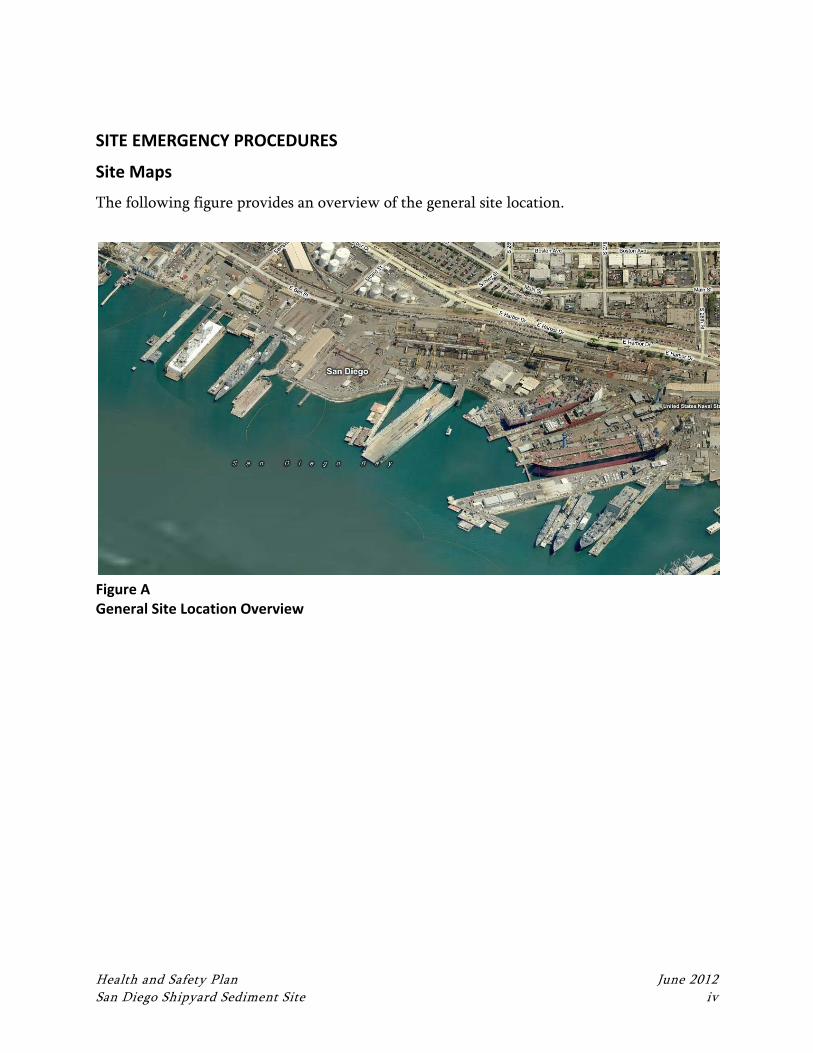
Health and Safety Plan June 2012 San Diego Shipyard Sediment Site iv
SITE EMERGENCY PROCEDURES
Site Maps
The following figure provides an overview of the general site location.
Figure A General Site Location Overview
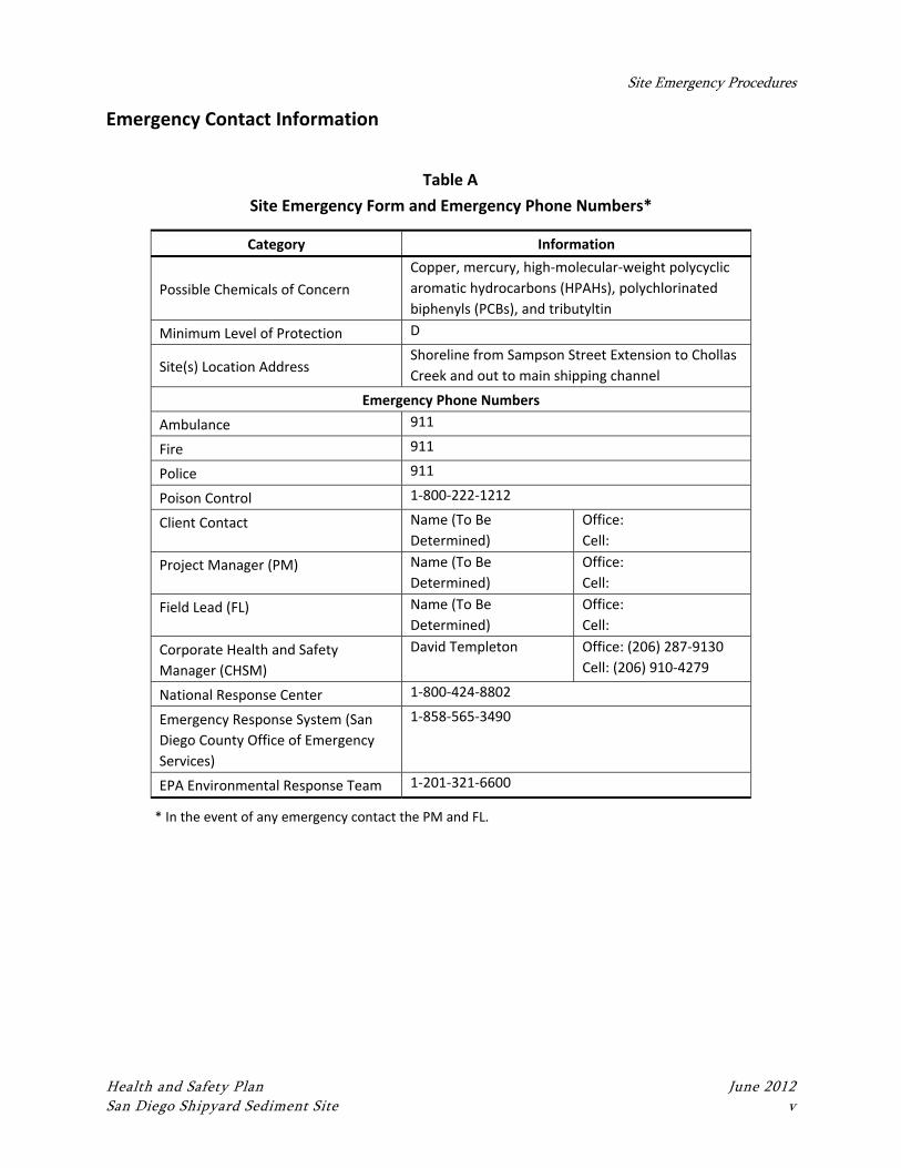
Site Emergency Procedures
Health and Safety Plan June 2012 San Diego Shipyard Sediment Site v
Emergency Contact Information
Table A
Site Emergency Form and Emergency Phone Numbers*
Category Information
Possible Chemicals of Concern
Copper, mercury, high‐molecular‐weight polycyclic
aromatic hydrocarbons (HPAHs), polychlorinated
biphenyls (PCBs), and tributyltin
Minimum Level of Protection D
Site(s) Location Address Shoreline from Sampson Street Extension to Chollas
Creek and out to main shipping channel
Emergency Phone Numbers
Ambulance 911
Fire 911
Police 911
Poison Control 1‐800‐222‐1212
Client Contact Name (To Be
Determined)
Office:
Cell:
Project Manager (PM) Name (To Be
Determined)
Office:
Cell:
Field Lead (FL) Name (To Be
Determined)
Office:
Cell:
Corporate Health and Safety
Manager (CHSM)
David Templeton Office: (206) 287‐9130
Cell: (206) 910‐4279
National Response Center 1‐800‐424‐8802
Emergency Response System (San
Diego County Office of Emergency
Services)
1‐858‐565‐3490
EPA Environmental Response Team 1‐201‐321‐6600
* In the event of any emergency contact the PM and FL.
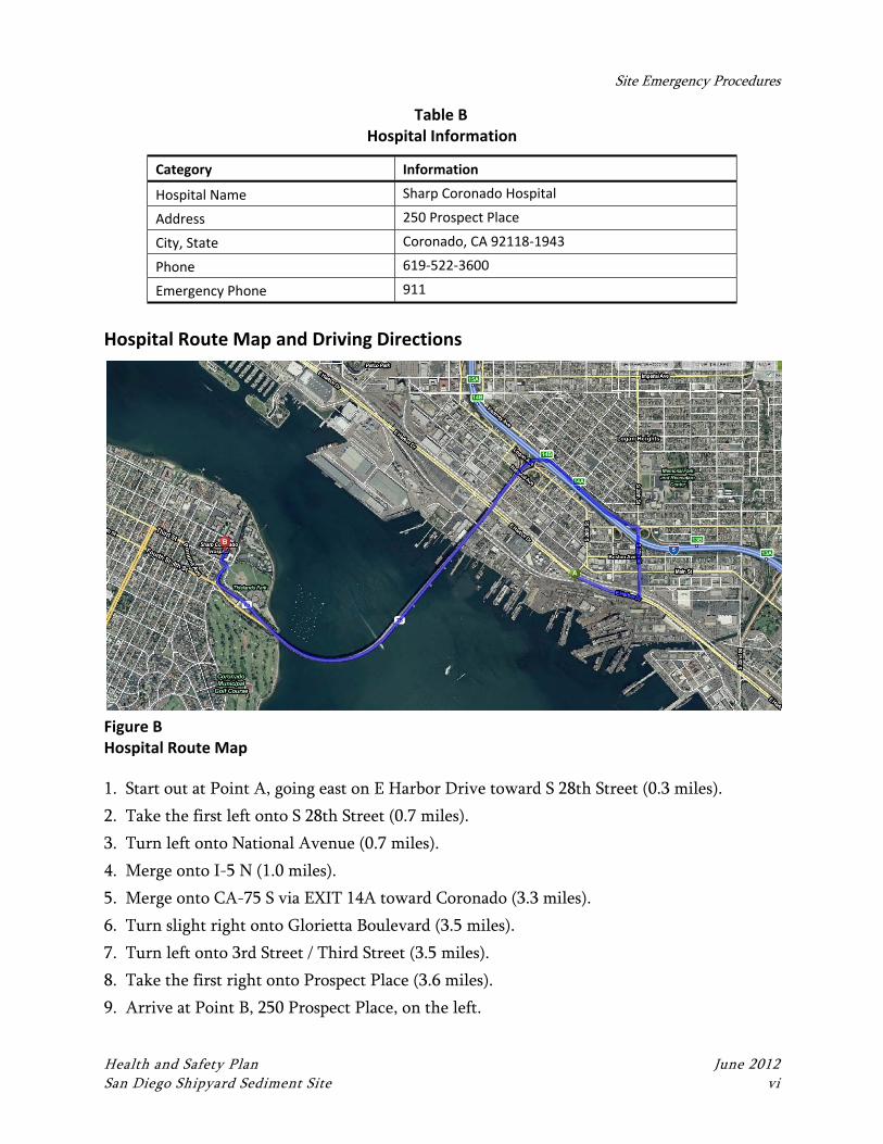
Site Emergency Procedures
Health and Safety Plan June 2012 San Diego Shipyard Sediment Site vi
Table B Hospital Information
Category Information
Hospital Name Sharp Coronado Hospital
Address 250 Prospect Place
City, State Coronado, CA 92118‐1943
Phone 619‐522‐3600
Emergency Phone 911
Hospital Route Map and Driving Directions
Figure B Hospital Route Map
1. Start out at Point A, going east on E Harbor Drive toward S 28th Street (0.3 miles).
2. Take the first left onto S 28th Street (0.7 miles).
3. Turn left onto National Avenue (0.7 miles).
4. Merge onto I-5 N (1.0 miles).
5. Merge onto CA-75 S via EXIT 14A toward Coronado (3.3 miles).
6. Turn slight right onto Glorietta Boulevard (3.5 miles).
7. Turn left onto 3rd Street / Third Street (3.5 miles).
8. Take the first right onto Prospect Place (3.6 miles).
9. Arrive at Point B, 250 Prospect Place, on the left.
Site Emergency Procedures
Health and Safety Plan June 2012 San Diego Shipyard Sediment Site vii
Key Safety Personnel
The following people share responsibility for health and safety at the site. See Section 4 of
this HASP for a description of the role and responsibility of each.
Client Contact: Name (To Be Determined) Office: (xxx) xxx-xxxx
Cell: (xxx) xxx-xxxx
Project Manager (PM): Name (To Be
Determined)
Office: (xxx) xxx-xxxx
Cell: (xxx) xxx-xxxx
Field Lead (FL): Name (To Be Determined) Office: (xxx) xxx-xxxx
Cell: (xxx) xxx-xxxx
Corporate Health and Safety Manager
(CHSM): David Templeton
Office: (206) 287-9130
Cell: (206) 910-4279
Emergency Response Procedures
In the event of an emergency, immediate action must be taken by the first person to
recognize the event. Use the following steps as a guideline:
Survey the situation to ensure that it is safe for you and the victim. Do not endanger
your own life. Do not enter an area to rescue someone who has been overcome
unless properly equipped and trained. Ensure that all protocols are followed. If
applicable, review Material Safety Data Sheets (MSDS) to evaluate response actions
for chemical exposures.
Call the appropriate emergency number (911) or direct someone else to do this
immediately (see Table A). Explain the physical injury, chemical exposure, fire, or
release and location of the incident.
Have someone retrieve the nearest first aid kit and Automatic External Defibrillator
(AED), if available. Note: Only use an AED if you have been properly trained and are
currently certified to do so.
Decontaminate the victim without delaying life-saving procedures (see Section 8).
Administer first aid and cardiopulmonary resuscitation (CPR), if properly trained,
until emergency responders arrive.
Notify the Project Manager (PM), Field Lead (FL), and owner.
Complete the appropriate incident investigation reports.
Site Emergency Procedures
Health and Safety Plan June 2012 San Diego Shipyard Sediment Site viii
First Aid and CPR Guidelines
Personnel qualified and current in basic first aid and/or CPR procedures may perform those
procedures as necessary. Personnel qualified and current in basic first aid and/or CPR are
protected under Good Samaritan policies as long as they only perform the basic tasks that
they were taught. Do not perform first aid and/or CPR tasks if you have not been trained in
first aid and/or CPR.
Injury Management/Incident Notification
Observe the following injury management/incident notification procedures and practices:
Injury Management
Once a personal injury incident is discovered, the first action will be to ensure that
the injured party receives appropriate medical attention.
If it is safe to do so, the nearest workers will immediately assist a person who shows
signs of medical distress or who is involved in an accident.
Render first aid and call 911 or the appropriate emergency number as soon as
possible.
Escort the injured person to the occupational clinic or hospital or arrange for an
ambulance.
Proceed immediately to Notification Requirements, below.
Notification Requirements
Directly after caring for an injured person, the FL will be summoned. The FL will
immediately make contact with the PM or other designated individual to alert them
of the medical emergency. The FL will advise them of the following:
Location of the victim at the work site
Nature of the emergency
Whether the victim is conscious
Specific conditions contributing to the injury, if known
Contact the PM (if not contacted previously) immediately.
Site Emergency Procedures
Health and Safety Plan June 2012 San Diego Shipyard Sediment Site ix
The PM will contact upper line management, and client representative(s) including
the Corporate Health and Safety Manager (CHSM).
The CHSM will facilitate the incident investigation.
All client requirements will also be adhered to pertinent to personal injury incident
reporting.
Incident Other Than Personal Injury
All incidents including, but not limited to, fire, explosion, property damage, or
environmental release will be responded to in accordance with the site-specific Health and
Safety Plan. In general, this includes securing the site appropriate to the incident, turning
control over to the emergency responders, or securing the site and summoning appropriate
remedial personnel or equipment. Anchor QEA will immediately notify the client of any
major incident, fire, equipment or property damage, or environmental incident with a
preliminary report. A full report will be provided within 72 hours.
Near‐Miss Reporting
All near-miss incidents (those that could have reasonably lead to an injury, environmental
release, or other incident) must also be reported to the FL and/or PM immediately so they
can take action to ensure that such conditions that lead to the near-miss incident can be
readily corrected in order to prevent future occurrences.
Spills and Releases of Hazardous Materials
When required, notify the National Response Center and local state agencies. The following
information should be provided to the National Response Center:
Name and telephone number
Name and address of facility
Time and type of incident
Name and quantity of materials involved, if known
Extent of injuries
Possible hazards to human health or the environment outside of the facility
Site Emergency Procedures
Health and Safety Plan June 2012 San Diego Shipyard Sediment Site x
The emergency telephone number for the National Response Center is 1-800-424-8802. If
hazardous waste has been released or produced through control of the incident, ensure that:
Waste is collected and contained
Containers of waste are removed or isolated from the immediate site of the
emergency
Treatment or storage of the recovered waste, contaminated soil or surface water, or
any other material that results from the incident or its control is provided
No waste that is incompatible with released material is treated or stored in the facility
until cleanup procedures are completed
Ensure that all emergency equipment used is decontaminated, recharged, and fit for its
intended use before operations are resumed.
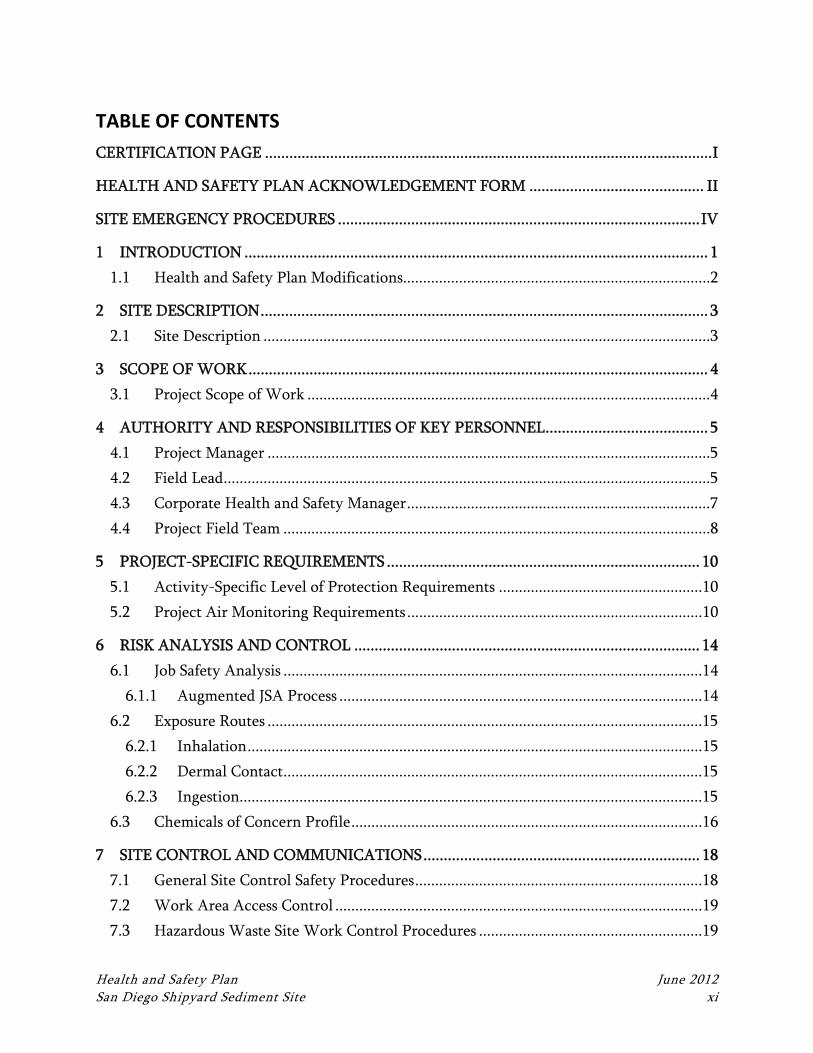
Health and Safety Plan June 2012 San Diego Shipyard Sediment Site xi
TABLE OF CONTENTS
CERTIFICATION PAGE .............................................................................................................. I
HEALTH AND SAFETY PLAN ACKNOWLEDGEMENT FORM ........................................... II
SITE EMERGENCY PROCEDURES ......................................................................................... IV
1 INTRODUCTION .................................................................................................................. 1
1.1 Health and Safety Plan Modifications.............................................................................2
2 SITE DESCRIPTION .............................................................................................................. 3
2.1 Site Description ................................................................................................................3
3 SCOPE OF WORK ................................................................................................................. 4
3.1 Project Scope of Work .....................................................................................................4
4 AUTHORITY AND RESPONSIBILITIES OF KEY PERSONNEL ........................................ 5
4.1 Project Manager ...............................................................................................................5
4.2 Field Lead ..........................................................................................................................5
4.3 Corporate Health and Safety Manager ............................................................................7
4.4 Project Field Team ...........................................................................................................8
5 PROJECT-SPECIFIC REQUIREMENTS ............................................................................. 10
5.1 Activity-Specific Level of Protection Requirements ...................................................10
5.2 Project Air Monitoring Requirements ..........................................................................10
6 RISK ANALYSIS AND CONTROL ..................................................................................... 14
6.1 Job Safety Analysis .........................................................................................................14
6.1.1 Augmented JSA Process ...........................................................................................14
6.2 Exposure Routes .............................................................................................................15
6.2.1 Inhalation ..................................................................................................................15
6.2.2 Dermal Contact .........................................................................................................15
6.2.3 Ingestion....................................................................................................................15
6.3 Chemicals of Concern Profile ........................................................................................16
7 SITE CONTROL AND COMMUNICATIONS .................................................................... 18
7.1 General Site Control Safety Procedures ........................................................................18
7.2 Work Area Access Control ............................................................................................19
7.3 Hazardous Waste Site Work Control Procedures ........................................................19
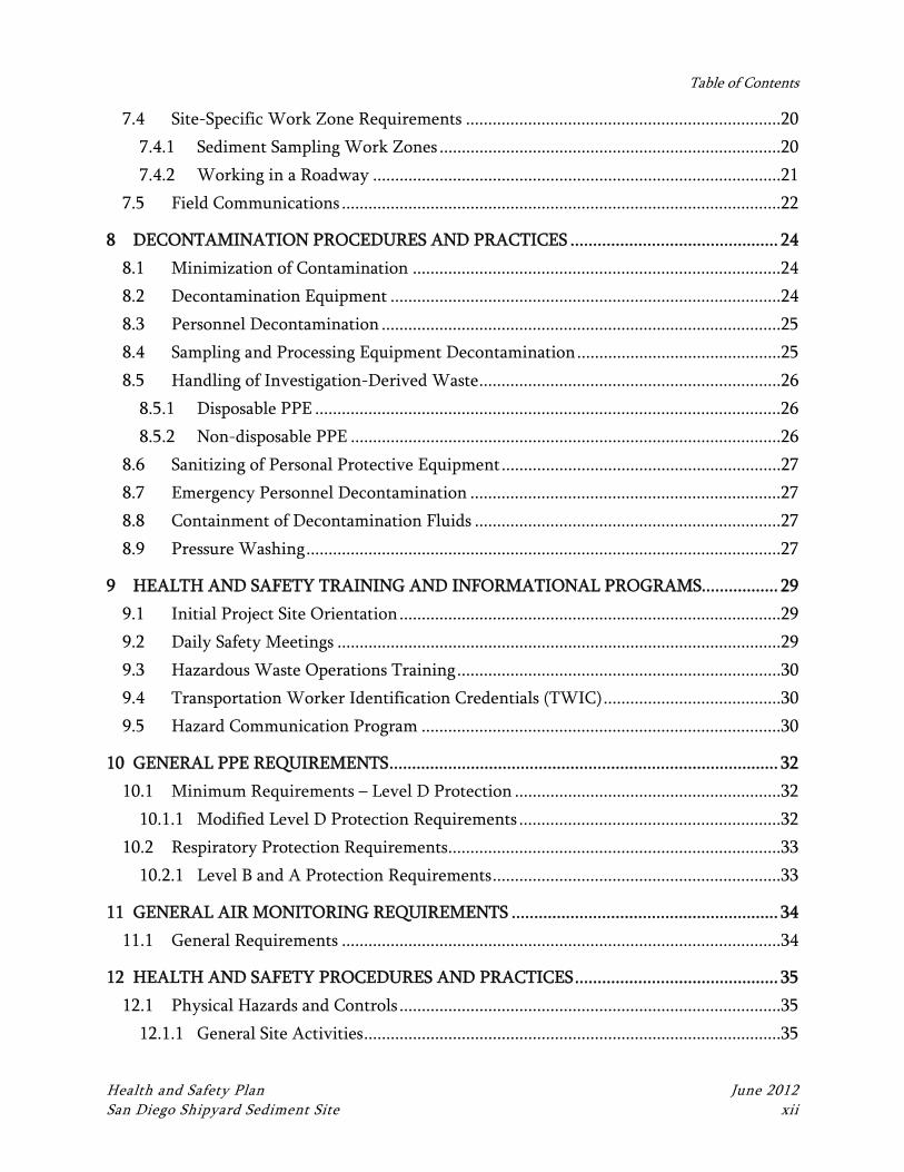
Table of Contents
Health and Safety Plan June 2012 San Diego Shipyard Sediment Site xii
7.4 Site-Specific Work Zone Requirements .......................................................................20
7.4.1 Sediment Sampling Work Zones .............................................................................20
7.4.2 Working in a Roadway ............................................................................................21
7.5 Field Communications ...................................................................................................22
8 DECONTAMINATION PROCEDURES AND PRACTICES .............................................. 24
8.1 Minimization of Contamination ...................................................................................24
8.2 Decontamination Equipment ........................................................................................24
8.3 Personnel Decontamination ..........................................................................................25
8.4 Sampling and Processing Equipment Decontamination ..............................................25
8.5 Handling of Investigation-Derived Waste ....................................................................26
8.5.1 Disposable PPE .........................................................................................................26
8.5.2 Non-disposable PPE .................................................................................................26
8.6 Sanitizing of Personal Protective Equipment ...............................................................27
8.7 Emergency Personnel Decontamination ......................................................................27
8.8 Containment of Decontamination Fluids .....................................................................27
8.9 Pressure Washing ...........................................................................................................27
9 HEALTH AND SAFETY TRAINING AND INFORMATIONAL PROGRAMS................. 29
9.1 Initial Project Site Orientation ......................................................................................29
9.2 Daily Safety Meetings ....................................................................................................29
9.3 Hazardous Waste Operations Training .........................................................................30
9.4 Transportation Worker Identification Credentials (TWIC) ........................................30
9.5 Hazard Communication Program .................................................................................30
10 GENERAL PPE REQUIREMENTS ...................................................................................... 32
10.1 Minimum Requirements – Level D Protection ............................................................32
10.1.1 Modified Level D Protection Requirements ...........................................................32
10.2 Respiratory Protection Requirements ...........................................................................33
10.2.1 Level B and A Protection Requirements .................................................................33
11 GENERAL AIR MONITORING REQUIREMENTS ........................................................... 34
11.1 General Requirements ...................................................................................................34
12 HEALTH AND SAFETY PROCEDURES AND PRACTICES ............................................. 35
12.1 Physical Hazards and Controls ......................................................................................35
12.1.1 General Site Activities ..............................................................................................35
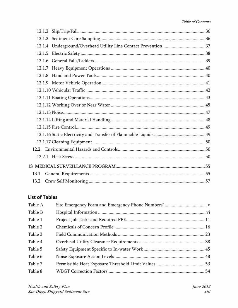
Table of Contents
Health and Safety Plan June 2012 San Diego Shipyard Sediment Site xiii
12.1.2 Slip/Trip/Fall .............................................................................................................36
12.1.3 Sediment Core Sampling ..........................................................................................36
12.1.4 Underground/Overhead Utility Line Contact Prevention .....................................37
12.1.5 Electric Safety ...........................................................................................................38
12.1.6 General Falls/Ladders ...............................................................................................39
12.1.7 Heavy Equipment Operations .................................................................................40
12.1.8 Hand and Power Tools .............................................................................................40
12.1.9 Motor Vehicle Operation .........................................................................................41
12.1.10 Vehicular Traffic ......................................................................................................42
12.1.11 Boating Operations ...................................................................................................43
12.1.12 Working Over or Near Water .................................................................................45
12.1.13 Noise ..........................................................................................................................47
12.1.14 Lifting and Material Handling .................................................................................48
12.1.15 Fire Control ...............................................................................................................49
12.1.16 Static Electricity and Transfer of Flammable Liquids ............................................49
12.1.17 Cleaning Equipment .................................................................................................50
12.2 Environmental Hazards and Controls ...........................................................................50
12.2.1 Heat Stress .................................................................................................................50
13 MEDICAL SURVEILLANCE PROGRAM ........................................................................... 55
13.1 General Requirements ...................................................................................................55
13.2 Crew Self Monitoring ....................................................................................................57
List of Tables
Table A Site Emergency Form and Emergency Phone Numbers* .................................... v
Table B Hospital Information ............................................................................................ vi
Table 1 Project Job Tasks and Required PPE................................................................... 11
Table 2 Chemicals of Concern Profile ............................................................................. 16
Table 3 Field Communication Methods .......................................................................... 23
Table 4 Overhead Utility Clearance Requirements ........................................................ 38
Table 5 Safety Equipment Specific to In-water Work .................................................... 45
Table 6 Noise Exposure Action Levels ............................................................................. 48
Table 7 Permissible Heat Exposure Threshold Limit Values .......................................... 53
Table 8 WBGT Correction Factors ................................................................................... 54
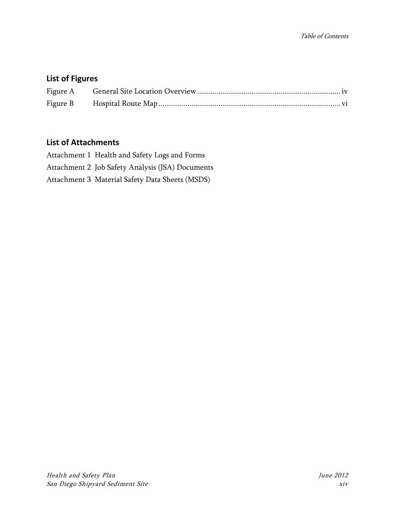
Table of Contents
Health and Safety Plan June 2012 San Diego Shipyard Sediment Site xiv
List of Figures
Figure A General Site Location Overview .......................................................................... iv
Figure B Hospital Route Map .............................................................................................. vi
List of Attachments
Attachment 1 Health and Safety Logs and Forms
Attachment 2 Job Safety Analysis (JSA) Documents
Attachment 3 Material Safety Data Sheets (MSDS)
Health and Safety Plan June 2012 San Diego Shipyard Sediment Site xv
LIST OF ACRONYMS AND ABBREVIATIONS
° C degrees Celsius
° F degrees Fahrenheit
ACGIH American Conference of Governmental Industrial Hygienists
AED Automated External Defibrillator
Anchor QEA Anchor QEA, L.P.
ANSI American National Standards Institute
APR Air-Purifying Respirator
ASTM American Society for Testing and Materials
CAO Cleanup and Abatement Order
CFR Code of Federal Regulations
CHSM Corporate Health and Safety Manager
COC chemical of concern
CPR Cardiopulmonary resuscitation
CRZ Contamination Reduction Zone
dbA A-weighted decibel
dB decibel
DOT U.S. Department of Transportation
EPA U.S. Environmental Protection Agency
eV electron volts
EZ Exclusion Zone/Hot Zone
FL Field Lead
GFCI Ground Fault Circuit Interrupter
H:V horizontal to vertical
HASP Health and Safety Plan
HAZMAT Hazardous Materials
HAZWOPER Hazardous Waste Operations and Emergency Response
HEPA High Efficiency Particulate Air
HMIS Hazardous Material Information System
HPAH high-molecular-weight polycyclic aromatic hydrocarbon
IP Ionization Potential
JSA Job Safety Analysis
List of Acronyms and Abbreviations
Health and Safety Plan June 2012 San Diego Shipyard Sediment Site xvi
kV kilovolts
LEL Lower Explosive Limit
LO/TO Lockout/Tagout
mg/m3 milligrams per cubic meter
MHR Maximum Heart Rate
MLLW mean lower low water
MSDS Material Safety Data Sheets
MUTCD Manual of Uniform Traffic Control Devices
NEC National Electrical Code
NFPA National Fire Protection Association
NIOSH National Institute for Occupational Safety and Health
NPL National Priority List
NRR Noise Reduction Rating
OEL Occupational Exposure Limit
OSHA Occupational Safety and Health Act or Administration
OV Organic Vapor
OVM Organic Vapor Monitor
PAHs polycyclic aromatic hydrocarbon
PCB polychlorinated biphenyl
PEL Permissible Exposure Limit
PFD personal flotation device
PM Project Manager
PPE Personal Protective Equipment
Project Team San Diego Shipyard Project Team
PVC Polyvinyl Chloride
QLFT Qualitative Fit Test
RAP Remedial Action Plan
REL Recommended Exposure Limits
RCRA Resource Conservation and Recovery Act
STEL Short Term Exposure Limit
SZ Support Zone/Clean Zone
TLV Threshold Limit Values
TSD Treatment, Storage, and Disposal Facility
TWA Time Weighted Average
List of Acronyms and Abbreviations
Health and Safety Plan June 2012 San Diego Shipyard Sediment Site xvii
TWIC Transportation Worker Identification Credentials
UL Underwriters Laboratories Inc.
USCG U.S. Coast Guard
VOC Volatile Organic Compound
WBGT Wet Bulb Globe Temperature
Health and Safety Plan June 2012 San Diego Shipyard Sediment Site 1
1 INTRODUCTION
This Health and Safety Plan (HASP) has been prepared on behalf of the San Diego Shipyard
Project Team (Project Team) and presents health and safety requirements and procedures
that will be followed by Project Team personnel and at a minimum by its subcontractors
during work activities at the San Diego Shipyard Sediment Site (the site). This HASP has
been developed in accordance with Title 29 of the Code of Federal Regulations (CFR), Part
1910.120 (b), and will be used in conjunction with Anchor QEA’s Corporate Health and
Safety Program. See Section 1.1 for HASP modification procedures.
The provisions of this HASP are mandatory for all Project Team personnel assigned to the
project. Subcontractors are also expected to follow the provisions of this HASP unless they
have their own HASP that covers their specific activities related to this project. Any
subcontractor HASPs must include the requirements set forth in this HASP, at a minimum.
All visitors to the work site must also abide by the requirements of this HASP and will attend
a pre-work briefing where the contents of this HASP will be presented and discussed.
Personnel assigned to work at the project site will be required to read this plan and must sign
the Health and Safety Plan Acknowledgement Form to confirm that they understand and
agree to abide by the provisions of the HASP.
Subcontractors are ultimately responsible for the health and safety of their employees.
Subcontractors may mandate health and safety protection measures for their employees
beyond the minimum requirements specified in this HASP.
The objectives of this HASP are to identify potential physical, chemical, and biological
hazards associated with field activities; establish safe working conditions and protective
measures to control those hazards; define emergency procedures; and describe the
responsibilities, training requirements, and medical monitoring requirements for site
personnel.
This HASP prescribes the procedures that must be followed during specific site activities.
Significant operational changes that could affect the health and safety of personnel, the
Introduction
Health and Safety Plan June 2012 San Diego Shipyard Sediment Site 2
community, or the environment will not be made without the prior approval of the Project
Manager (PM) and the Corporate Health and Safety Manager (CHSM).
Issuance of this approved plan documents that the workplace has been evaluated for hazards.
A hazard assessment has been performed and the adequacy of the personal protective
equipment (PPE) selected was evaluated as required by 29 CFR 1910.132(d) - Personal
Protective Equipment, General Requirements (general industry), 1910.134 – Respiratory
Protection, 1926.28 – Personal Protective Equipment (construction industry), and 1926.55 –
Gases, vapors, fumes, dusts and mist, and is duly noted by the signature(s) and date appearing
on the certification page of this document.
1.1 Health and Safety Plan Modifications
This HASP will be modified by amendment, if necessary, to address changing field
conditions or additional work tasks not already described in this document. Modifications
will be proposed by the Field Lead (FL) using the “Modification to Health and Safety Plan”
form included in Attachment 1. Modifications will be reviewed by the CHSM or authorized
representative and approved by the PM.
Health and Safety Plan June 2012 San Diego Shipyard Sediment Site 3
2 SITE DESCRIPTION
2.1 Site Description
The study area for the sediment removal project is located along the eastern shore of central
San Diego Bay, extending approximately from the Sampson Street Extension on the
northwest to Chollas Creek on the southeast, and from the shoreline out to the San Diego
Bay main shipping channel to the west. The site comprises approximately 15.2 acres that are
subject to dredging and 2.3 acres that are subject to clean sand cover, primarily under piers.
The project consists of marine sediments in the bottom bay waters that contain elevated
levels of pollutants above San Diego Bay background conditions. This area, combined with
the potential upland staging areas are collectively referred to as the “project site.”
The principal structural components within the site include the concrete bulkheads, piers,
and dry dock facilities associated with the two shipyard facilities. Bathymetry at the site
varies substantially due to the presence of shipways, dry docks, and berths, and ranges from
-2 mean lower low water (MLLW) along the bulkheads to -70 feet MLLW at the BAE
Systems dry dock sump area. The marine habitat within the sediment removal area contains
both vegetated and un-vegetated subtidal soft-bottom habitats, pier pilings, and bulkhead
walls. The vegetated habitat species include sparse beds of eelgrass (Zostera marina). The
entire extent of the sediment removal area shoreline is artificially stabilized and generally
consists of a vertical sheetpile bulkhead and seawall. The marine habitat types include
vertical bulkhead walls and dock structures, vegetated and un-vegetated soft-bottom subtidal
habitats, and open water. These habitats support marine plants, invertebrates, and fish.
Additional information regarding the site is presented in the Remedial Action Plan (RAP).
Health and Safety Plan June 2012 San Diego Shipyard Sediment Site 4
3 SCOPE OF WORK
3.1 Project Scope of Work
Currently, the site is subject to a Cleanup and Abatement Order (CAO) requiring the
submittal of a RAP, to which this HASP is appended. As described in the RAP, the planned
remedial action consists of mechanical dredging of impacted sediments. As part of the design
and implementation of the RAP, the following potential field activities are addressed in
concept by this HASP. Upon finalization of specific work tasks, task-specific Job Safety
Analyses (JSAs) will be completed and added to the HASP (JSAs are discussed in more detail
in Section 6.1).
Pre-design field activities
Sediment, surface water, or soil sampling activities
Non-invasive assessments (bathymetric surveys, habitat inspections)
Construction observation
Water quality monitoring activities
Sediment confirmatory sampling
As stated above, the HASP addresses these potential work tasks in concept and provides
information and procedures that assume a general approach to these tasks, based on Anchor
QEA experience conducting similar tasks at multiple sediment cleanup sites. Specific data,
where available (such as chemicals of concern [COCs]), are included in the HASP.
Health and Safety Plan June 2012 San Diego Shipyard Sediment Site 5
4 AUTHORITY AND RESPONSIBILITIES OF KEY PERSONNEL
This section describes the authority and responsibilities of key Anchor QEA project
personnel. The names and contact information for the following key safety personnel are
listed in the Emergency Site Procedures section at the beginning of this HASP. Should key
site personnel change during the course of the project, a new list will be established and
posted immediately at the site. The emergency phone number for the site is 911, and should
be used for all medical, fire, and police emergencies.
4.1 Project Manager
The PM provides overall direction for the project. The PM is responsible for ensuring that
the project meets the client’s objectives in a safe and timely manner. The PM is responsible
for providing qualified staff for the project and adequate resources and budget for the health
and safety staff to carry out their responsibilities during the field work. The PM will be in
regular contact with the FL and CHSM to ensure that appropriate health and safety
procedures are implemented into each project task.
The PM has authority to direct response operations; the PM assumes total control over
project activities but may assign responsibility for aspects of the project to others. In
addition, the PM:
Oversees the preparation and organization of background review of the project, the
work plan, and the field team.
Ensures that the team obtains permission for site access and coordinates activities
with appropriate officials.
Briefs the FL and field personnel on specific assignments.
Together with the FL, sees that health and safety requirements are met.
Consults with the CHSM regarding unsafe conditions, incidents, or changes in site
conditions or the scope of work.
4.2 Field Lead
The FL reports to the PM, has authority to direct response operations, and assumes control
over on-site activities. The FL will direct field activities, coordinate the technical and health
and safety components of the field program, and is responsible in general for enforcing this
Authority and Responsibilities of Key Personnel
Health and Safety Plan June 2012 San Diego Shipyard Sediment Site 6
site-specific HASP and Corporate Health and Safety Program requirements. The FL will be
the primary point of contact for all field personnel and visitors and has direct responsibility
for implementation and administration of this HASP. The FL and any other member of the
field crew have STOP WORK AUTHORITY—the authority to stop or suspend work in the
event of an emergency, if conditions arise that pose an unacceptable health and safety risk to
the field crew or environment, or if conditions arise that warrant revision or amendment of
this HASP. The following include, but are not necessarily limited to, the functions of the FL
related to this HASP:
Conduct and document daily safety meetings, or designate an alternate FL in his or
her absence.
Execute the work plan and schedule.
Conduct periodic field health and safety inspections to ensure compliance with this
HASP.
Oversee implementation of safety procedures.
Implement worker protection levels.
Enforce site control measures to ensure that only authorized personnel are allowed on
site.
Notify, when necessary, local public emergency officials (all personnel on site may
conduct this task as needed).
Follow-up on incident reports to the PM.
Periodically inspect protective clothing and equipment for adequacy and safety
compliance.
Ensure that protective clothing and equipment are properly stored and maintained.
Perform or oversee air monitoring in accordance with this HASP.
Maintain and oversee operation of monitoring equipment and interpretation of data
from the monitoring equipment.
Monitor workers for signs of stress, including heat stress, cold exposure, and fatigue.
Require participants to use the “buddy” system.
Provide (via implementation of this HASP) emergency procedures, evacuation routes,
and telephone numbers of the local hospital, poison control center, fire department,
and police department.
Communicate incidents promptly to the PM.
Maintain communication with the CHSM on site activities.
If applicable, ensure that decontamination and disposal procedures are followed.
Authority and Responsibilities of Key Personnel
Health and Safety Plan June 2012 San Diego Shipyard Sediment Site 7
Maintain the availability of required safety equipment.
Advise appropriate health services and medical personnel of potential exposures.
Notify emergency response personnel in the event of an emergency and coordinate
emergency medical care.
The FL will record health-and-safety-related details of the project in the field logbook. At a
minimum, each day’s entries must include the following information:
Project name or location
Names of all on-site personnel
Level of PPE worn and any other specifics regarding PPE
Weather conditions
Type of field work being performed
The FL will have completed the required Occupational Safety and Health Administration
(OSHA) 40-hour Hazardous Waste Operations and Emergency Response (HAZWOPER)
training and annual updates, the 8-hour Supervisor training, medical monitoring clearance,
and current first aid and cardiopulmonary resuscitation (CPR) training. Other certifications
or training may be stipulated based on client or site requirements.
4.3 Corporate Health and Safety Manager
The CHSM (or his/her designee) will be responsible for managing on-site health and safety
activities and will provide support to the PM and FL on health and safety issues. The specific
duties of the CHSM are to:
Provide technical input into the design and implementation of this HASP.
Advise on the potential for occupational exposure to project hazards, along with
appropriate methods and/or controls to eliminate site hazards.
Ensure that a hazard assessment has been performed and that the adequacy of the
PPE selected was evaluated as required by 29 CFR 1910.132(d), 1910.134, 1926.25,
and 1926.55, and is duly noted by the signatures and date appearing on the
Certification Page of this document.
Consult with the FL on matters relating to suspending site activities in the event of an
emergency.
Authority and Responsibilities of Key Personnel
Health and Safety Plan June 2012 San Diego Shipyard Sediment Site 8
Verify that all on-site Anchor QEA personnel and subcontractors have read and
signed the HASP Acknowledgement Form.
Verify that corrective actions resulting from deficiencies identified by audit and
observations are implemented and effective.
The CHSM or his/her designee will have completed the required OSHA 40-hour
HAZWOPER training and annual updates, the 8-hour Supervisor training, and have medical
monitoring clearance. In addition, the CHSM or his/her designee will have current training
in first aid and CPR.
4.4 Project Field Team
All project field team members will attend a project-specific meeting conducted by the FL
concerning safety issues and project work task review before beginning work. All field crew,
including subcontractors, must be familiar with and comply with this HASP. The field crew
has the responsibility to immediately report any potentially unsafe or hazardous conditions
to the FL, and all members of the field crew have STOP WORK AUTHORITY—the
authority to stop or suspend work if conditions arise that pose an unacceptable health and
safety risk to the field crew or environment, or if conditions arise that warrant revision or
amendment of this HASP. The field team reports to the FL for on-site activities and is
responsible for:
Reviewing and maintaining a working knowledge of this HASP
Safe completion of on-site tasks required to fulfill the work plan
Compliance with the HASP
Attendance and participation in daily safety meetings
Notification to the FL of existing or potential safety conditions at the site
Reporting all incidents to the FL
Demonstrating safety and health conscious conduct
Per OSHA 1910.120(e)(3)(i)1, newly assigned HAZWOPER 40-hour trained field team
members must have at least 3 days of field work supervised by an experienced FL (preferably
1 “General site workers (such as equipment operators, general laborers and supervisory personnel) engaged in
hazardous substance removal or other activities which expose or potentially expose workers to hazardous
Authority and Responsibilities of Key Personnel
Health and Safety Plan June 2012 San Diego Shipyard Sediment Site 9
an individual with HAZWOPER Supervisor training). It is the responsibility of the PM to
identify such “short service” personnel and ensure that their supervised field experience
occurs (or has occurred) and is documented in the project field notes and on the Daily Safety
Briefing form (Attachment 1).
substances and health hazards shall receive a minimum of 40 hours of instruction off the site, and a minimum of
three days actual field experience under the direct supervision of a trained experienced supervisor.”
Health and Safety Plan June 2012 San Diego Shipyard Sediment Site 10
5 PROJECT‐SPECIFIC REQUIREMENTS
This section provides activity-specific levels of protection and air monitoring requirements
to be used on this site based on the scope of work and the COCs.
5.1 Activity‐Specific Level of Protection Requirements
Refer to Section 10 of this plan for general requirements for PPE. Level D is the minimum
acceptable level for most sites. An upgrade to Modified Level D occurs when there is a
possibility that contaminated media can come in contact with the skin or work uniform. An
upgrade to Level C occurs when there is a potential for exposure to airborne COCs; i.e., if the
results of air monitoring reveal that action levels have been exceeded. Hearing protection
must be worn when there are high noise levels. Workers must maintain proficiency in the
use and care of PPE that is to be worn.
It is assumed at this time that only Level D and Modified Level D will be required for on-site
work. If conditions or requirements dictate the need for Level C or higher, this HASP will
be amended accordingly.
Table 1, Project Job Tasks and Required PPE, describes the specific means of protection
needed for the conceptual work activities.
5.2 Project Air Monitoring Requirements
It is assumed at this time that only Level D and Modified Level D will be required for on-site
work and, accordingly, air monitoring is not required. As such, if conditions or requirements
dictate the need for air monitoring, this HASP will be amended accordingly.
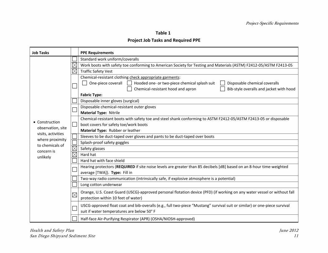
Project-Specific Requirements
Health and Safety Plan June 2012 San Diego Shipyard Sediment Site 11
Table 1
Project Job Tasks and Required PPE
Job Tasks PPE Requirements
Construction
observation, site
visits, activities
where proximity
to chemicals of
concern is
unlikely
Standard work uniform/coveralls
Work boots with safety toe conforming to American Society for Testing and Materials (ASTM) F2412‐05/ASTM F2413‐05
Traffic Safety Vest
Chemical‐resistant clothing check appropriate garments:
One‐piece coverall Hooded one‐ or two‐piece chemical splash suit Disposable chemical coveralls
Chemical‐resistant hood and apron Bib‐style overalls and jacket with hood
Fabric Type:
Disposable inner gloves (surgical)
Disposable chemical‐resistant outer gloves
Material Type: Nitrile
Chemical‐resistant boots with safety toe and steel shank conforming to ASTM F2412‐05/ASTM F2413‐05 or disposable
boot covers for safety toe/work boots
Material Type: Rubber or leather
Sleeves to be duct‐taped over gloves and pants to be duct‐taped over boots
Splash‐proof safety goggles
Safety glasses
Hard hat
Hard hat with face shield
Hearing protectors (REQUIRED if site noise levels are greater than 85 decibels [dB] based on an 8‐hour time‐weighted
average [TWA]). Type: Fill in
Two‐way radio communication (intrinsically safe, if explosive atmosphere is a potential)
Long cotton underwear
Orange, U.S. Coast Guard (USCG)‐approved personal flotation device (PFD) (if working on any water vessel or without fall
protection within 10 feet of water)
USCG‐approved float coat and bib‐overalls (e.g., full two‐piece “Mustang” survival suit or similar) or one‐piece survival
suit if water temperatures are below 50° F
Half‐face Air‐Purifying Respirator (APR) (OSHA/NIOSH‐approved)
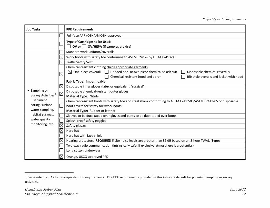
Project-Specific Requirements
Health and Safety Plan June 2012 San Diego Shipyard Sediment Site 12
Job Tasks PPE Requirements
Full‐face APR (OSHA/NIOSH‐approved)
Type of Cartridges to be Used:
OV or OV/HEPA (if samples are dry)
Sampling or
Survey Activities2
– sediment
coring, surface
water sampling,
habitat surveys,
water quality
monitoring, etc.
Standard work uniform/coveralls
Work boots with safety toe conforming to ASTM F2412‐05/ASTM F2413‐05
Traffic Safety Vest
Chemical‐resistant clothing check appropriate garments:
One‐piece coverall Hooded one‐ or two‐piece chemical splash suit Disposable chemical coveralls
Chemical‐resistant hood and apron Bib‐style overalls and jacket with hood
Fabric Type: Impermeable
Disposable inner gloves (latex or equivalent “surgical”)
Disposable chemical‐resistant outer gloves
Material Type: Nitrile
Chemical‐resistant boots with safety toe and steel shank conforming to ASTM F2412‐05/ASTM F2413‐05 or disposable
boot covers for safety toe/work boots
Material Type: Rubber or leather
Sleeves to be duct‐taped over gloves and pants to be duct‐taped over boots
Splash‐proof safety goggles
Safety glasses
Hard hat
Hard hat with face shield
Hearing protectors (REQUIRED if site noise levels are greater than 85 dB based on an 8‐hour TWA). Type:
Two‐way radio communication (intrinsically safe, if explosive atmosphere is a potential)
Long cotton underwear
Orange, USCG‐approved PFD
2 Please refer to JSAs for task-specific PPE requirements. The PPE requirements provided in this table are default for potential sampling or survey
activities.
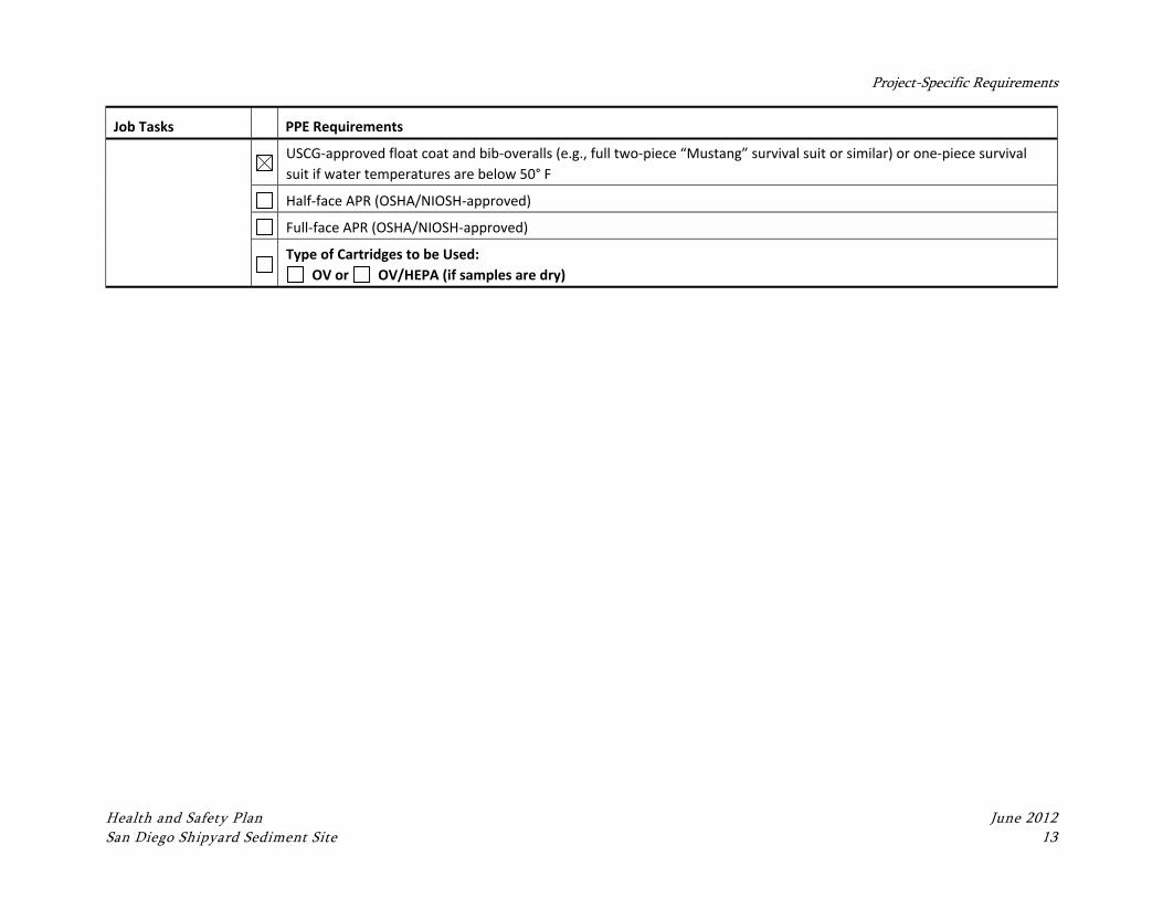
Project-Specific Requirements
Health and Safety Plan June 2012 San Diego Shipyard Sediment Site 13
Job Tasks PPE Requirements
USCG‐approved float coat and bib‐overalls (e.g., full two‐piece “Mustang” survival suit or similar) or one‐piece survival
suit if water temperatures are below 50° F
Half‐face APR (OSHA/NIOSH‐approved)
Full‐face APR (OSHA/NIOSH‐approved)
Type of Cartridges to be Used:
OV or OV/HEPA (if samples are dry)
Health and Safety Plan June 2012 San Diego Shipyard Sediment Site 14
6 RISK ANALYSIS AND CONTROL
The following sections discuss the potential worker health and safety hazards associated with
potential field tasks for this project. These hazards are addressed through the mechanical
and physical control measures, use of PPE, monitoring, training, decontamination,
emergency response, and safety procedures.
Significant changes in the scope of work covered by this HASP must be communicated to the
PM and CHSM, and an amendment to this HASP must be created as needed (see Section 1.1).
Any task conducted beyond those identified in the scope of work and this HASP must be
evaluated using the JSA process prior to conducting the work.
6.1 Job Safety Analysis
As specific work tasks are identified and designed, JSA documents will be developed that
detail the chemical, physical, and biological hazards associated with these tasks, along with
the specific control measures (e.g., engineering controls, administrative controls, and/or PPE)
that will be used to ensure that these tasks are conducted in a safe manner.
The PM and FL are responsible for identifying work tasks and project site conditions that are
beyond the previously developed JSA documents and for communicating such information to
the CHSM. The CHSM will provide support, as needed, to the PM and/or the FL, who will
have primary responsibility to develop project-specific JSAs.
The contents of the JSA documents shall be communicated to project personnel during the
site orientation meeting and during daily safety meetings when conducting work where the
specific JSAs are applicable.
A JSA template document is located in Attachment 2 of this HASP.
6.1.1 Augmented JSA Process
If significant work tasks are identified during the course of the project that were not
previously addressed in the current JSA documentation at that time, then a task-specific JSA
document must be developed at the project site prior to conducting the work. The PM
Risk Analysis and Control
Health and Safety Plan June 2012 San Diego Shipyard Sediment Site 15
and/or FL shall develop this document(s) with input from the CHSM, as needed, and this
HASP will be amended to include the document (see Section 1.1 for HASP modification
procedures). Project personnel shall be trained on the contents of the developed task-
specific JSA prior to its implementation. A copy of the task-specific JSA form used in this
process is supplied in Attachment 2 of this HASP.
6.2 Exposure Routes
Possible routes of exposure to the chemicals potentially encountered on this project include
inhalation, dermal contact, and ingestion of dust, mist, gas, vapor, or liquid. Exposure will be
minimized by using safe work practices and by wearing the appropriate PPE. A further
discussion of PPE requirements is presented in Section 10.
6.2.1 Inhalation
Inhalation of particulates, dust, mist, gas, or vapor during field activities is possible.
Whenever possible, work activities will be oriented so that personnel are upwind of the
sampling location. An organic vapor monitor (OVM) may be used to monitor ambient air
and the breathing zone within the work area for organic compounds. The need for and
details of task-specific air monitoring will be evaluated during identification and design of
specific tasks.
6.2.2 Dermal Contact
Dermal contact with potentially contaminated soil, sediment, or surface water during field
activities is possible. Direct contact will be minimized through the use of appropriate PPE
and decontamination procedures.
6.2.3 Ingestion
Direct ingestion of contaminants can occur by inhaling airborne dust, mist, or vapors, or by
swallowing contaminants trapped in the upper respiratory tract. Indirect ingestion can occur
by introducing the contaminants into the mouth by way of food, tobacco, fingers, or other
carriers. Although ingestion of contaminants can occur, proper hygiene, decontamination,
and contamination reduction procedures should reduce the probability of this route of
exposure.
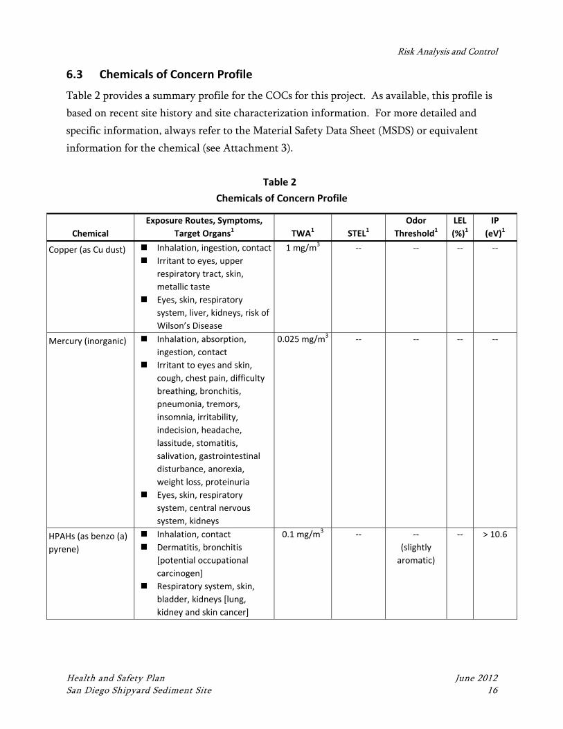
Risk Analysis and Control
Health and Safety Plan June 2012 San Diego Shipyard Sediment Site 16
6.3 Chemicals of Concern Profile
Table 2 provides a summary profile for the COCs for this project. As available, this profile is
based on recent site history and site characterization information. For more detailed and
specific information, always refer to the Material Safety Data Sheet (MSDS) or equivalent
information for the chemical (see Attachment 3).
Table 2
Chemicals of Concern Profile
Chemical
Exposure Routes, Symptoms,
Target Organs1 TWA1 STEL1
Odor
Threshold1
LEL
(%)1
IP
(eV)1
Copper (as Cu dust) Inhalation, ingestion, contact
Irritant to eyes, upper
respiratory tract, skin,
metallic taste
Eyes, skin, respiratory
system, liver, kidneys, risk of
Wilson’s Disease
1 mg/m3 ‐‐ ‐‐ ‐‐ ‐‐
Mercury (inorganic) Inhalation, absorption,
ingestion, contact
Irritant to eyes and skin,
cough, chest pain, difficulty
breathing, bronchitis,
pneumonia, tremors,
insomnia, irritability,
indecision, headache,
lassitude, stomatitis,
salivation, gastrointestinal
disturbance, anorexia,
weight loss, proteinuria
Eyes, skin, respiratory
system, central nervous
system, kidneys
0.025 mg/m3 ‐‐ ‐‐ ‐‐ ‐‐
HPAHs (as benzo (a)
pyrene)
Inhalation, contact
Dermatitis, bronchitis
[potential occupational
carcinogen]
Respiratory system, skin,
bladder, kidneys [lung,
kidney and skin cancer]
0.1 mg/m3 ‐‐ ‐‐
(slightly
aromatic)
‐‐ > 10.6
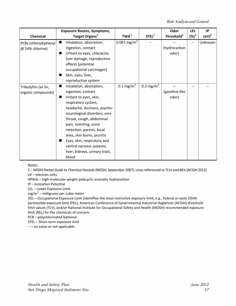
Risk Analysis and Control
Health and Safety Plan June 2012 San Diego Shipyard Sediment Site 17
Chemical
Exposure Routes, Symptoms,
Target Organs1 TWA1 STEL1
Odor
Threshold1
LEL
(%)1
IP
(eV)1
PCBs (chlorodiphenyl
@ 54% chlorine)
Inhalation, absorption,
ingestion, contact
Irritant to eyes, chloracne,
liver damage, reproductive
effects [potential
occupational carcinogen]
Skin, eyes, liver,
reproductive system
0.001 mg/m3 ‐‐ ‐‐
(hydrocarbon
odor)
‐‐ Unknown
Tributyltin (as Sn,
organic compounds)
Inhalation, absorption,
ingestion, contact
Irritant to eyes, skin,
respiratory system,
headache, dizziness, psycho‐
neurological disorders, sore
throat, cough, abdominal
pain, vomiting, urine
retention, paresis, focal
anes, skin burns, pruritis
Eyes, skin, respiratory and
central nervous systems,
liver, kidneys, urinary tract,
blood
0.1 mg/m3 0.2 mg/m3 ‐‐
(gasoline‐like
odor)
‐‐ ‐‐
Notes: 1 – NIOSH Pocket Guide to Chemical Hazards (NIOSH, September 2007), cross referenced to TLVs and BEIs (ACGIH 2012) eV – electron volts HPAHs – high‐molecular‐weight polycyclic aromatic hydrocarbon IP – Ionization Potential LEL – Lower Explosive Limit mg/m3 – milligrams per cubic meter OEL – Occupational Exposure Limit (identifies the most restrictive exposure limit, e.g., federal or state OSHA permissible exposure limit (PEL), American Conference of Governmental Industrial Hygienists (ACGIH) threshold limit values (TLV), and/or National Institute for Occupational Safety and Health (NIOSH) recommended exposure limit (REL) for the chemicals of concern. PCB – polychlorinated biphenyl STEL – Short‐term exposure limit ‐‐ – no value or not applicable
Health and Safety Plan June 2012 San Diego Shipyard Sediment Site 18
7 SITE CONTROL AND COMMUNICATIONS
The primary purposes for site controls are to establish the hazardous area perimeter, to
reduce migration of contaminants into clean areas, and to prevent unauthorized access or
exposure to hazardous materials by site personnel and the public. Site control is especially
important in emergency situations.
7.1 General Site Control Safety Procedures
The following are standard safe work practices that apply to all Anchor QEA site personnel
and subcontractors and shall be discussed in the safety briefing prior to initiating work on
the site:
Eating, drinking, chewing gum or tobacco, and smoking are prohibited on site except
in designated areas.
Hands and faces must be washed upon leaving the work area and before eating,
drinking, chewing gum or tobacco, and smoking.
A buddy system will be used. Radio or hand signals will be established to maintain
communication.
During site operations, each worker will consider him/herself as a safety backup to
his/her partner.
Visual contact will be maintained between buddies on-site when performing
hazardous duties.
No personnel will be admitted to the site without the proper safety equipment,
training, and medical surveillance certification.
All personnel must comply with established safety procedures. Any staff member
who does not comply with safety policy, as established in this HASP, will be subject
to corrective action, potentially including, but not limited to, reprimanded and
immediate dismissal.
Proper decontamination procedures must be followed before leaving a contaminated
work area.
Site Control and Communications
Health and Safety Plan June 2012 San Diego Shipyard Sediment Site 19
7.2 Work Area Access Control
If work is performed in public areas, the following precautions shall be taken to protect both
the workers and the public. Access control to the work area will be accomplished by the use
of a combination of the following devices and/or methods:
Fences and/or barricades
Traffic control devices and/or use of flaggers
Caution tape
Other methods to keep the site secure and provide a visual barrier to help keep
unauthorized personnel from entering the site and active work areas
7.3 Hazardous Waste Site Work Control Procedures
To prevent contamination from migrating from personnel and equipment, work areas will be
clearly specified as an Exclusion Zone/Hot Zone (EZ), Contaminant Reduction Zone (CRZ),
or Support Zone/Clean Zone (SZ) prior to beginning operations. Each work area will be
clearly identified using signs or physical barriers. At the end of each workday, the site
should be secured and/or guarded to prevent unauthorized entry.
Site work zones will include:
Exclusion Zone/Hot Zone (EZ). The EZ will be the “hot zone” or contaminated area
inside the site perimeter (or sample collection area of boat). The EZ is the defined
area where potential respiratory and/or health hazards exist. All personnel entering
the EZ must use the required PPE, as set forth in this HASP, and meet the appropriate
training and medical clearance. Entry to and exit from this zone will be made
through a designated point. Appropriate warning signs to identify the EZ should be
posted (e.g., DANGER, AUTHORIZED PERSONNEL ONLY, PROTECTIVE
EQUIPMENT REQUIRED BEYOND THIS POINT). Personnel and equipment
decontamination must be performed upon exiting the EZ.
Contaminant Reduction Zone (CRZ). The CRZ, also known as the “warm zone,” is a
transitional zone between the EZ and the SZ (also known as the “cold zone” or “clean
zone”). The CRZ provides a location for removal and decontamination of PPE and
tools leaving the EZ. A separate decontamination area will be established for heavy
equipment. All personnel and equipment must exit via the CRZ. If, at anytime, the
CRZ is compromised, a new CRZ will be established.
Site Control and Communications
Health and Safety Plan June 2012 San Diego Shipyard Sediment Site 20
Support Zone/Clean Zone (SZ). This uncontaminated zone will be the area outside
the EZ and CRZ and within the geographic perimeters of the site (including boat and
processing areas). The SZ is used for support personnel; staging materials; parking
vehicles; office, laboratory, and sanitation facilities; and receiving deliveries.
Personnel entering this zone may include delivery personnel, visitors, security guards,
and others who will not necessarily be permitted in the EZ or CRZ.
A log of all personnel visiting, entering, or working on the site shall be maintained by the FL.
No visitor will be allowed in the EZ without showing proof of training and medical
certification, per 29 CFR 1910.120(e), (f) (and 29 CFR 1926.1101(k)(9), (m) if appropriate).
Visitors will attend a site orientation given by the FL and sign the HASP.
7.4 Site‐Specific Work Zone Requirements
This section contains guidelines for maintaining safe conditions when working from a boat,
in a roadway, or at an excavation site.
7.4.1 Sediment Sampling Work Zones
This subsection contains guidelines concerning health and safety aboard marine sampling
vessels. The vessel captain, onshore coring operator, and the FL will delineate the
boundaries of the work zones aboard the vessel and will inform the field crews of the
arrangement. The purpose of the zones is to limit the migration of sample material out of the
zones and to restrict access to active work areas.
Two work zones will be observed aboard the vessel. One will encompass the “moonhole” of
the vessel where the samplers will be deployed and recovered. Only the coring crew may
enter this zone unless assistance is required by other personnel. The second work zone will
be a sample processing area on the vessel. The contractor crew will deliver sediment core
tubes to this zone and open them. Anchor QEA personnel will log and process the sediment
cores either on the boat or on shore.
Both the collection and processing areas on the vessel and onshore will have a SZ outside the
CRZ to stage clean equipment, don PPE, take rest breaks, or perform any other site activities
that do not involve potentially contaminated materials.
Site Control and Communications
Health and Safety Plan June 2012 San Diego Shipyard Sediment Site 21
7.4.1.1 Vessel Decontamination Area
A station will be set up for decontaminating sample processing equipment and personnel
gear such as boots or PPE. The station will have the buckets, brushes, soapy water, rinse
water, or wipes necessary to perform decontamination operations. Plastic bags will be
provided for expendable and disposable materials. The decontamination fluids will be stored
in sealable containers and will be properly disposed of.
7.4.1.2 Access Control
Security and control of access to the sampling vessel and onshore area will be the
responsibility of the captain and FL. Additional security measures may be placed into effect
by the client, or as required by national security threat levels determined by the federal
government. Access to the vessel and onshore areas will only be granted to necessary project
personnel and authorized visitors. Any security or access control problems will be reported
to the client or appropriate authorities.
7.4.1.3 Safety Equipment
In addition to PPE that will be worn by shipboard personnel, basic emergency and first aid
equipment will also be provided. Equipment will include:
U.S. Coast Guard (USCG)-approved personal flotation devices (PFDs)
First aid kit adequate for the number of personnel
Emergency eyewash
Anchor QEA and/or subconsultants will provide this equipment, which must be at the
location(s) where field activities are being performed. Equipment will be checked daily to
ensure its readiness for use.
7.4.2 Working in a Roadway
Work conducted in public streets may require coordination with local city and/or county
governments and development and submittal of a traffic control plan in accordance with the
U.S. Department of Transportation (DOT) Manual on Uniform Traffic Control Devices
Site Control and Communications
Health and Safety Plan June 2012 San Diego Shipyard Sediment Site 22
(MUTCD). Use of personnel qualified as Flaggers may also be required to provide temporary
traffic control.
Observe the following site control practices and procedures when working in roadways:
Wear a traffic vest and hardhat when a vehicle hazard exists.
Use cones, flag-mounted cones, caution tape, and/or barricades.
Use a vehicle strobe light and block area with truck.
Develop a traffic flow plan for high-traffic situations (as appropriate):
Use a flag person
Use a flashing arrow sign
Use “MEN WORKING” signs liberally
Obtain lane closing permits
Engage police details
See Sections 12.1.9 and 12.1.10 for additional information regarding motor vehicle operation
and vehicular traffic.
7.5 Field Communications
Communications between all Project Team representatives and subcontractors at the work
site can be verbal and/or non-verbal. Verbal communication can be affected by the on-site
background noise and various PPE. See Table 3 for a list of the types of communication
methods and equipment to use, depending on site conditions. Communication equipment
must be checked daily to ensure proper operation. All project personnel must be initially
briefed on the communication methods prior to starting work; communication methods
should be reviewed in daily safety meetings.
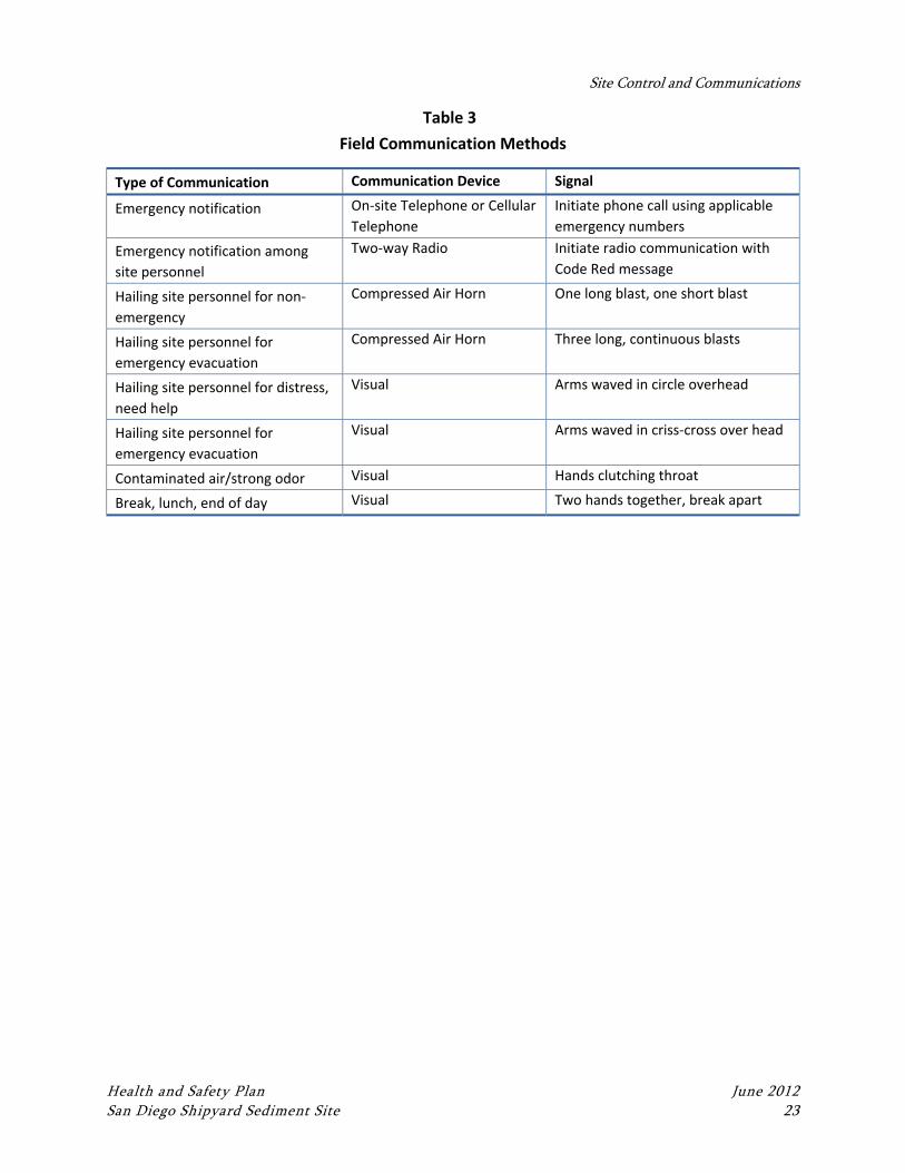
Site Control and Communications
Health and Safety Plan June 2012 San Diego Shipyard Sediment Site 23
Table 3
Field Communication Methods
Type of Communication Communication Device Signal
Emergency notification On‐site Telephone or Cellular
Telephone
Initiate phone call using applicable
emergency numbers
Emergency notification among
site personnel
Two‐way Radio Initiate radio communication with
Code Red message
Hailing site personnel for non‐
emergency
Compressed Air Horn One long blast, one short blast
Hailing site personnel for
emergency evacuation
Compressed Air Horn Three long, continuous blasts
Hailing site personnel for distress,
need help
Visual Arms waved in circle overhead
Hailing site personnel for
emergency evacuation
Visual Arms waved in criss‐cross over head
Contaminated air/strong odor Visual Hands clutching throat
Break, lunch, end of day Visual Two hands together, break apart
Health and Safety Plan June 2012 San Diego Shipyard Sediment Site 24
8 DECONTAMINATION PROCEDURES AND PRACTICES
8.1 Minimization of Contamination
The following measures will be observed to prevent or minimize exposure to potentially
contaminated materials:
Personnel
Do not walk through spilled materials
Do not handle, touch, or smell sample media directly
Make sure PPE has no cuts or tears prior to use
Protect and cover any skin injuries
Stay upwind of airborne dusts and vapors
Do not eat, drink, chew tobacco, or smoke in the work zones
Sampling Equipment and Vehicles/Vessels
Use care to avoid getting sampled media on the outside of sample containers
If necessary, bag sample containers before filling with sampled media
Place clean equipment on a plastic sheet to avoid direct contact with contaminated
media
Keep contaminated equipment and tools separate from clean equipment and tools
Fill sample containers over a plastic tub to contain spillage
Clean up spilled material immediately to avoid tracking around the vehicle/vessel
8.2 Decontamination Equipment
All vehicles, vessels, and equipment that have entered potentially contaminated areas will be
visually inspected and, if necessary, decontaminated prior to leaving the area. If the level of
vehicle contamination is low, decontamination may be limited to rinsing tires and wheel
wells with an appropriate detergent and water. If the vehicle is significantly contaminated,
steam cleaning or pressure washing may be required. Tools will be cleaned in the same
manner. Rinsate from all decontamination activities will be collected for proper disposal.
Decontamination of equipment and tools will take place within the CRZ.
Decontamination Procedures and Practices
Health and Safety Plan June 2012 San Diego Shipyard Sediment Site 25
The following supplies will be available to perform decontamination activities (additional or
differing decontamination procedures may be identified for specific tasks):
Wash and rinse buckets
Tap water and phosphate-free detergent
Scrub brushes
Distilled/deionized water
Deck pump with pressurized freshwater hose (aboard the vessel)
Pressure washer/steam cleaner, if appropriate
Paper towels and plastic garbage bags
8.3 Personnel Decontamination
The FL will ensure that all site personnel are familiar with personnel decontamination
procedures as listed below. All personnel wearing PPE in a work area (EZ) must undergo
decontamination prior to entering the SZ. Personnel will perform the following
decontamination procedures:
Wash and rinse outer gloves and boots in portable buckets to remove gross
contamination.
If suit is heavily soiled, rinse it off.
Remove outer gloves; inspect and discard if damaged. Leave inner gloves on.
Personnel will remove their outer garment and gloves, dispose of them, and properly
label container or drum. Personnel will then decontaminate their hard hats and boots
with an aqueous solution of detergent or other appropriate cleaning solution. These
items then will be hand-carried to the next station. Remove inner gloves.
Thoroughly wash hands and face before leaving CRZ.
Sanitize respirators and place in a clean plastic bag.
8.4 Sampling and Processing Equipment Decontamination
To prevent sample cross-contamination, sampling and processing equipment in contact with
soil, sediment, or water samples will undergo the following decontamination procedures
when work is completed in the CRZ and prior to additional use:
1. Rinse with potable water and wash with scrub brush.
2. Wash with phosphate-free detergent (Alconox®).
Decontamination Procedures and Practices
Health and Safety Plan June 2012 San Diego Shipyard Sediment Site 26
3. Visually inspect the sampler and repeat the scrub and rinse step, if necessary. If
scrubbing and rinsing with Alconox® is insufficient to remove visually observable
tar-related contamination on equipment, the equipment will be scrubbed and rinsed
using hexane (or similar type solution) until all visual signs of contamination are
absent.
4. Rinse external sampling equipment with potable water three times prior to use. Rinse
homogenizing equipment once with potable water and three times with distilled
water prior to and between sample processing.
8.5 Handling of Investigation‐Derived Waste
All remaining soil or sediment, fluids used for decontamination of sampling equipment, and
sample collection disposable wastes (e.g., gloves, paper towels, foil, or others) will be placed
into appropriate containers and staged on site for disposal.
8.5.1 Disposable PPE
Disposable PPE may include Tyvek suits, inner latex gloves, and respirator cartridges.
Dispose of PPE according to the requirements of the client and state and federal agencies.
8.5.2 Non‐disposable PPE
Non-disposable PPE may include respirators and boots and gloves. When decontaminating
respirators, observe the following practices and procedures:
Wipe out the respirator with a disinfecting pad prior to donning.
Decontaminate the respirator on site at the close of each day with an approved
sanitizing solution.
When decontaminating boots and gloves, observe the following practices and procedures:
Decontaminate the boots or gloves outside with a solution of detergent and water;
rinse with water prior to leaving the site.
Protect the boots or gloves from exposure by covering with disposable covers such as
plastic to minimize required decontamination activities.
Decontamination Procedures and Practices
Health and Safety Plan June 2012 San Diego Shipyard Sediment Site 27
8.6 Sanitizing of Personal Protective Equipment
Respirators, reusable protective clothing, and other personal articles must not only be
decontaminated before being reused, but also sanitized. The insides of masks and clothing
become soiled due to exhalation, body oils, and perspiration. Manufacturer's instructions
should be used to sanitize respirator masks. If practical, reusable protective clothing should
be machine-washed after a thorough decontamination; otherwise, it must be cleaned by
hand.
8.7 Emergency Personnel Decontamination
Personnel with medical problems or injuries may also require decontamination. There is the
possibility that the decontamination may aggravate or cause more serious health effects. If
prompt lifesaving, first aid, and medical treatment are required, decontamination procedures
will be omitted. In either case, a member of the site management team will accompany
contaminated personnel to the medical facility to advise on matters involving
decontamination.
8.8 Containment of Decontamination Fluids
As necessary, spill control measures will be used to contain contaminated runoff that may
enter into clean areas. Use plastic sheeting, hay bales, or install a spill control system to
prevent spills and contain contaminated water.
8.9 Pressure Washing
The following procedure is required when using high-pressure washing equipment for
decontamination purposes:
Wear modified Level D protection, including a face shield and safety goggles.
Ensure that other personnel are out of the area prior to decontamination.
Secure the area around the decontamination pad with cones, caution tape, or
barricades.
Ensure that safe work practices and precautions are taken to minimize the potential
for physical injury from high-pressure water spray. Follow the manufacturer’s
operating instructions.
The pressure washer wand must be equipped with a safety release handle.
Decontamination Procedures and Practices
Health and Safety Plan June 2012 San Diego Shipyard Sediment Site 28
Ensure that the area is clean after equipment is decontaminated. Barricades, cones, or
caution tape must be left in place and secured at all times.
Health and Safety Plan June 2012 San Diego Shipyard Sediment Site 29
9 HEALTH AND SAFETY TRAINING AND INFORMATIONAL PROGRAMS
This section describes the health and safety training and informational programs that
Anchor QEA project site personnel must comply with.
9.1 Initial Project Site Orientation
Work on the project site will require participation in an initial health and safety orientation
presented by the PM or FL that will consist of, at a minimum, the following topics:
A review of the contents of this HASP, including the scope of work and associated
site hazards and control methods and procedures.
Provisions of this plan are mandatory for all personnel assigned to the project.
Subcontractors are also expected to follow the provisions of this plan unless they have
their own HASP that covers their specific activities related to this project and
includes the minimum requirements of this HASP.
Visitors to the work site may be required to abide by the requirements of this plan.
Personnel assigned to perform work at the project site, working under the provisions
of this HASP, will be required to read the plan and must sign the Health and Safety
Plan Acknowledgement Form to confirm that they understand and agree to abide by
the provisions of this plan. Personnel not directly affiliated with the project (i.e.,
visitors) may also be required to sign an indemnity form.
9.2 Daily Safety Meetings
Daily safety meetings (“tailgate meetings”) make accident prevention a top priority for
everyone and reinforce awareness of important accident-prevention techniques. The
following daily safety meeting procedures and practices are required:
Daily safety meetings will be held each morning prior to conducting site activities.
The Daily Safety Briefing form in Attachment 1 will be used to document each
meeting.
Copies of the completed Daily Safety Briefing forms will be maintained on-site during
the course of the project.
Health and Safety Training and Informational Programs
Health and Safety Plan June 2012 San Diego Shipyard Sediment Site 30
9.3 Hazardous Waste Operations Training
Personnel working on project sites that present a potential exposure to hazardous wastes or
other hazardous substances shall be trained in accordance with the requirements of the 29
CFR 1910.120 (HAZWOPER) regulation. Training requirements will consist of the
following:
Field personnel must complete a minimum of 40 hours of hazardous waste activity
instruction.
Field personnel must complete a minimum of 3 days of supervised field instruction.
Field personnel assigned to the site will also have received 8 hours of refresher
training if the time lapse since their previous training has exceeded 1 year.
On-site managers and supervisors directly responsible for employees engaged in
hazardous waste operations will receive an additional 8 hours of supervisory training.
Field personnel shall be current in first aid/CPR training.
Other training may be required depending on the task to be performed (e.g., confined
space, excavation/trenching, underground storage tank removal, fall protection,
respiratory protection, and hazard communication).
9.4 Transportation Worker Identification Credentials (TWIC)
All Anchor QEA field personnel will maintain current TWIC status, pursuant to the
Maritime Transportation Security Act of 2002, unless this requirement is waived specifically
in writing by relevant property owners.
9.5 Hazard Communication Program
The purpose of hazard communication (Employee Right-to-Know) is to ensure that the
hazards of all chemicals located at the field project site are communicated to all Anchor QEA
personnel and subcontractors according to 29 CFR 1926.59.
Every container of hazardous materials must be labeled by the manufacturer, who must also
provide a MSDS upon initial order of the product and upon request thereafter. The actual
format may differ from company to company (e.g., National Fire Protection Association
[NFPA], Hazardous Material Information System [HMIS], or other), but the labels must
Health and Safety Training and Informational Programs
Health and Safety Plan June 2012 San Diego Shipyard Sediment Site 31
contain similar types of information. Maintain manufacturer labels if at all possible. The
label may use words or symbols to communicate the following:
The name of the chemical
The name, address, and emergency telephone number of the company that made or
imported the chemical
The physical hazards (Will it explode or catch fire? Is it reactive? Is it radioactive?)
Any important storage or handling instruction
The health hazards (Is it toxic? Could it cause cancer? Is it an irritant? What is the
target organ?)
The basic protective clothing, equipment, and procedures that are recommended
when working with the chemical
Upon identification and design of specific work tasks, MSDS for all chemicals brought onto
the site or anticipated to be encountered on site shall be appended in Attachment 3 of this
HASP. These MSDS shall be readily available for reference by site personnel and emergency
response personnel.
Hazardous materials received without proper labels shall be set aside and not distributed for
use until properly labeled.
If a hazardous chemical is transferred into a portable container (approved safety can), even if
it is for immediate use only, the contents of the portable container (for example, acetone,
gasoline, etc.) must be identified.
Health and Safety Plan June 2012 San Diego Shipyard Sediment Site 32
10 GENERAL PPE REQUIREMENTS
The minimum level of PPE should be selected according to the hazards that may be
encountered during site activities in accordance with established U.S. Environmental
Protection Agency (EPA) levels of protection (D and C). Only PPE that meets American
National Standards Institute (ANSI) standards shall be worn. Workers must maintain
proficiency in the use and care of PPE.
Refer to Section 5 of this plan for site-specific job task and level-of-protection requirements.
10.1 Minimum Requirements – Level D Protection
The minimum level of protection on project sites will be Level D protection, which consists
of the following equipment:
Standard work uniform/coveralls
Work boots with safety toe conforming to American Society for Testing and Materials
(ASTM) F2412-05/ASTM F2413-05
Approved safety glasses or goggles (meets ANSI Z87.1 – 1989 requirements for eye
protection)
Hard hat (meets ANSI Z89.1 – 1986 requirements for head protection)
Traffic safety vest
Hearing protection when there are high noise levels
Level D protection will be used only when:
The atmosphere contains no known hazards
Work functions preclude splashes, immersions, or the potential for unexpected
inhalation of, or contact with, hazardous concentrations of chemicals
Atmospheric concentrations of contaminants are less than the Permissible Exposure
Limit (PEL) and/or Threshold Limit Value (TLV)
10.1.1 Modified Level D Protection Requirements
Depending on the future field tasks and the potential hazards to be encountered, Level D
protection shall be modified to include additional protective equipment such as USCG-
approved PFDs, face shields/goggles, chemical-resistant clothing, and disposable gloves of
General PPE Requirements
Health and Safety Plan June 2012 San Diego Shipyard Sediment Site 33
varying materials depending on the chemical substances involved. An upgrade to Modified
Level D occurs when there is a possibility that contaminated media can contact the skin or
work uniform.
10.2 Respiratory Protection Requirements
Respiratory protection is not anticipated at this time for field tasks on this project.
10.2.1 Level B and A Protection Requirements
An upgrade to Level B protection occurs when the results of air monitoring reveal that action
levels have been exceeded (site personnel must meet training requirements). Prior to
upgrading to Level B, stop work and contact the PM and/or FL and CHSM if air monitoring
results exceed the Level C protection levels.
Health and Safety Plan June 2012 San Diego Shipyard Sediment Site 34
11 GENERAL AIR MONITORING REQUIREMENTS
11.1 General Requirements
Air monitoring is not anticipated at this time for field tasks on this project. However, in the
event that air monitoring is deemed necessary, this section provides reference information.
Specific air monitoring procedures and action levels will be determined at that time.
In general, air monitoring shall be conducted when the possibility of hazardous atmospheres,
chemical volatilization, or contaminated airborne dust exists (e.g., from intrusive activities
involving contaminated soils and/or groundwater, developing new monitoring wells, wells
containing known COCs, confined space entry, or others).
Health and Safety Plan June 2012 San Diego Shipyard Sediment Site 35
12 HEALTH AND SAFETY PROCEDURES AND PRACTICES
In addition to the task-specific JSAs that would be created, listed in Section 6.1, and
presented in Attachment 2 of this HASP, this section lists the health and safety procedures
and practices applicable to the tasks reasonably foreseen for this project. For additional
information, consult with the PM.
12.1 Physical Hazards and Controls
12.1.1 General Site Activities
Observe the following general procedures and practices to prevent physical hazards:
Legible and understandable precautionary labels shall be affixed prominently to
containers of potentially contaminated soil, sediment, water, and clothing.
No food or beverages shall be present or consumed in areas that have the potential to
contain COCs and/or contaminated materials or equipment.
No tobacco products or cosmetics shall be present or used in areas that have the
potential to contain COCs and/or contaminated materials or equipment.
An emergency eyewash unit shall be located immediately adjacent to employees who
handle hazardous or corrosive materials, including decontamination fluids. All
operations involving the potential for eye injury or splash must have approved
eyewash units locally available capable of delivering at least 0.4 gallons per minute for
at least 15 minutes.
On a project-specific basis, personnel working on or near bodies of water shall wear
USCG-approved PFDs.
Certain project sites may have newly finished work (e.g., concrete, paving, framing,
habitat reconstruction, or sediment caps) that may be damaged by unnecessary
contact, or that could cause dangerous conditions for personnel (e.g., slipping,
sinking, or tripping). Personnel working in or around these areas shall communicate
with the PM, FL, and property owner as needed to prevent damaging new work or
entering dangerous conditions.
Generally, all on-site activities will be conducted during daylight hours. If work after
dusk is planned or becomes necessary due to an emergency, adequate lighting must be
provided.
Health and Safety Procedures and Practices
Health and Safety Plan June 2012 San Diego Shipyard Sediment Site 36
Hazardous work, such as handling hazardous materials and heavy loads and
equipment operation, should not be conducted during severe storms.
All temporary electrical power must have a ground fault circuit interrupter (GFCI) as
part of its circuit if the circuit is not part of permanent wiring. All equipment must
be suitable and approved for the class of hazard present.
12.1.2 Slip/Trip/Fall
Observe the following procedures and practices to prevent slips, trips, and falls:
Inspect each work area for slip/trip/fall potential prior to each work task.
Slip/trip/fall hazards identified must be communicated to all personnel. Hazards
identified shall be corrected or labeled with warning signs to be avoided.
All personnel must be aware of their surroundings and maintain constant
communication with each other at all times.
12.1.3 Sediment Core Sampling
Sediment samples will be collected using a “Mud Mole” or vibracore sampling equipment
operated from a boat. Please see Section 12.1.12 for additional safety information regarding
working on or near the water.
All operations involving the use of powered sediment coring rigs will follow generally
accepted drilling/coring practices. One person will be assigned the responsibility of Lead
Driller/Corer. Additional personnel will assist with equipment as needed. The Lead
Driller/Corer will be responsible for operating the drilling/coring rig and ensuring safety.
General rules associated with drilling/coring rig operations will be as follows:
While drilling, all non-essential personnel shall remain at a distance that is past the
radius of any moving parts.
All operators and crew members will be familiar with the rig operations and will have
received practical training.
All personnel will be instructed in the use of the emergency kill switch/shutdown on
the drill rig.
Health and Safety Procedures and Practices
Health and Safety Plan June 2012 San Diego Shipyard Sediment Site 37
No loose-fitting clothing, jewelry, or free long hair is permitted near the drilling rig
or moving machinery parts.
A first aid kit and fire extinguisher will be available at all times.
No drilling will occur during impending electrical storms or tornadoes, or when rain,
ice, snow, or wind conditions create undue potential hazards.
Never allow “horsing around” within the vicinity of the drill rig and tool and supply
storage areas, even when the drill rig is shut down.
12.1.4 Underground/Overhead Utility Line Contact Prevention
Observe the following underground/overhead utility line contact prevention procedures and
practices:
Prior to conducting work, the PM or FL shall ensure that all existing underground or
overhead utilities in the work area are located per the state or local mark-out
methods. Documentation of utility mark-out shall be completed using the Utility
Contact Prevention Checklist form (see Attachment 1). No excavation work is to be
performed until all utility mark-outs are verified.
The PM or FL shall conduct a site survey to search for signs of other buried or
overhead utilities. The results of such surveys shall be documented on the Utility
Mark-out documentation form.
The property owner or facility operator shall be consulted on the issue of
underground utilities. As-built drawings shall be reviewed, when available, to verify
that underground utility locations are consistent with the utility location mark-outs.
All knowledge of past and present utilities must be evaluated prior to conducting
work.
If on-site subsurface utility locations are in question, a private locating service shall be
contacted to verify locations. If the investigation calls for boreholes in an area not
covered by the municipal One-Call system, then a private utility locate firm shall be
contacted to determine the location of other underground utilities.
The PM shall have documented verbal contact and an agreement with the fiber optic
company for all work within 50 feet of any fiber optic cables.
Only hand digging is permitted within 3 feet of underground high voltage, product,
or gas lines. Once the line is exposed, heavy equipment can be used, but must remain
at least 3 feet from the exposed line.
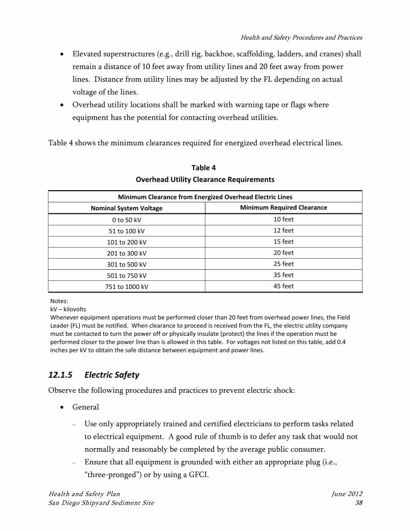
Health and Safety Procedures and Practices
Health and Safety Plan June 2012 San Diego Shipyard Sediment Site 38
Elevated superstructures (e.g., drill rig, backhoe, scaffolding, ladders, and cranes) shall
remain a distance of 10 feet away from utility lines and 20 feet away from power
lines. Distance from utility lines may be adjusted by the FL depending on actual
voltage of the lines.
Overhead utility locations shall be marked with warning tape or flags where
equipment has the potential for contacting overhead utilities.
Table 4 shows the minimum clearances required for energized overhead electrical lines.
Table 4
Overhead Utility Clearance Requirements
Minimum Clearance from Energized Overhead Electric Lines
Nominal System Voltage Minimum Required Clearance
0 to 50 kV 10 feet
51 to 100 kV 12 feet
101 to 200 kV 15 feet
201 to 300 kV 20 feet
301 to 500 kV 25 feet
501 to 750 kV 35 feet
751 to 1000 kV 45 feet
Notes: kV – kilovolts Whenever equipment operations must be performed closer than 20 feet from overhead power lines, the Field Leader (FL) must be notified. When clearance to proceed is received from the FL, the electric utility company must be contacted to turn the power off or physically insulate (protect) the lines if the operation must be performed closer to the power line than is allowed in this table. For voltages not listed on this table, add 0.4 inches per kV to obtain the safe distance between equipment and power lines.
12.1.5 Electric Safety
Observe the following procedures and practices to prevent electric shock:
General
Use only appropriately trained and certified electricians to perform tasks related
to electrical equipment. A good rule of thumb is to defer any task that would not
normally and reasonably be completed by the average public consumer.
Ensure that all equipment is grounded with either an appropriate plug (i.e.,
“three-pronged”) or by using a GFCI.
Health and Safety Procedures and Practices
Health and Safety Plan June 2012 San Diego Shipyard Sediment Site 39
Test all GFCIs prior to use.
Use only extension cords that are in good condition—if in doubt, throw it out.
Use only 16-gauge, heavy duty, three-wire, Underwriters Laboratories Inc. (UL)-
approved three-pronged extension cords
Be sure to locate extension cords out of traffic areas or, if this is unavoidable, flag
cords and protect workers from tripping over them (i.e., use barricades, tape the
cord down, etc.)
Do not stage extension cords or powered equipment in wet areas, to the degree
possible. Elevate cords and equipment out of puddles.
Specific
If unsure if a task requires specific electrical training, err on the side of caution
and contact the PM and FL prior to proceeding.
If subsurface work is to be performed, follow the guidelines in Section 12.1.4 and
conduct utility locating prior to work and in accordance with local ordinances.
If lock out/tag out (LO/TO) procedures are required (i.e., de-energizing machinery
or equipment so work may be performed), the equipment owner must provide
LO/TO procedures and training. By default, the equipment owner should perform
any LO/TO. If it becomes necessary for Anchor QEA personnel to perform
LO/TO tasks, contact the PM and FL prior to doing so.
Maintain appropriate distance from overhead utilities (see Table 4).
If unexpected electrical equipment is encountered (i.e., buried wire) assume it is
live, stop work, and contact the PM and FL immediately.
12.1.6 General Falls/Ladders
Observe the following general falls/ladders procedures and practices:
Assess work areas for fall hazards. A fall protection system that meets OSHA and
ANSI Z3591 standards must be used if work is conducted 6 feet or more above the
surface.
Use Type 1A rated ladders.
Make sure ladder rungs are sturdy and free of cracks.
Use ladders with secure safety feet.
Pitch ladders at a 4 horizontal to 1 vertical (4H:1V) ratio.
Secure ladders at the top or have another person at the bottom to help stabilize it.
Health and Safety Procedures and Practices
Health and Safety Plan June 2012 San Diego Shipyard Sediment Site 40
Ladders used to access an upper landing surface shall extend at least 3 feet above the
upper landing surface.
Use non-conductive ladders near electrical wires.
The top rung of a ladder should not be used as a step.
Do not carry any object or load that could cause a loss of balance or a fall.
12.1.7 Heavy Equipment Operations
Observe the following heavy equipment operations procedures and practices:
Wear leather gloves while attaching support members to protect against pinching
injuries.
While working from elevated levels greater than 6 feet, ensure that all employees
have fall protection that meets OSHA and ANSI Z3591 standards.
Do not stand under loads that are being raised or lowered with cranes or aerial lifts.
The subcontractor or Anchor QEA equipment operator must conduct pre-operational
inspections of all equipment. In addition, daily inspections will be conducted on the
equipment prior to site activities.
Maintain the appropriate distance from overhead utilities (see Table 4).
Always stay out of the swing radius of all heavy equipment. Always use a spotter
during movement of equipment. The spotter and others, as appropriate, shall
maintain constant communication with the operator.
All operators must have adequate training and be qualified to operate the particular
heavy equipment unit.
Conduct a site evaluation to determine proper positioning for the unit. Make sure the
surface is level. Cordon off holes, drop-offs, bumps, or weak ground surfaces.
When using a crane, do not use hands when the load is being lifted or lowered. Use
non-conductive tag line to help direct and position the load.
Never climb a raised platform or stand on the mid-rail or top-rail.
Tools should always be hung or put into a belt whenever possible
12.1.8 Hand and Power Tools
Observe the following procedures and practices when working with hand and power tools:
Keep hand tools sharp, clean, oiled, dressed, and not abused.
Health and Safety Procedures and Practices
Health and Safety Plan June 2012 San Diego Shipyard Sediment Site 41
Worn tools are dangerous. For example, the “teeth” in a pipe wrench can slip if worn
smooth, an adjustable wrench will slip if the jaws are sprung, and hammerheads can
fly off loose handles.
Tools subject to impact (e.g., chisels, star drills, and caulking irons) tend to
“mushroom.” Keep them dressed to avoid flying spalls. Use tool holders.
Do not force tools beyond their capacity.
Flying objects can result from operating almost any power tool, so always warn
people in the vicinity and use proper eye protection.
Each power tool should be examined before use for damaged parts, loose fittings, and
frayed or cut electric cords. Tag and return defective tools for repairs. Also inspect
for adequate lighting, proper lubrication, and abandoned tools or material that could
“vibrate into trouble.”
Compressed air must be shut off or the electric cord unplugged before making tool
adjustments. Air must be “bled down” before replacement or disconnection.
Proper guards or shields must be installed on all power tools before issue. Do not use
improper tools or tools without guards in place.
Replace all guards before start-up. Remove cranks, keys, or wrenches used in service
work.
12.1.9 Motor Vehicle Operation
All drivers are required to have a valid driver’s license, and all vehicles must have
appropriate state vehicle registration and inspection stickers. The use of hand-held wireless
devices is prohibited by Anchor QEA while driving any vehicle for business use at any time,
for personal use during business hours, and as defined by law. Additionally, site-specific
motor vehicle requirements must be followed, if any.
When driving to, from, and within the job site, be aware of potential hazards including:
Vehicle accidents
Distractions
Fatigue
Weather and road conditions
Health and Safety Procedures and Practices
Health and Safety Plan June 2012 San Diego Shipyard Sediment Site 42
To mitigate these hazards, observe the following procedures and practices regarding motor
vehicle operation:
Wear a seat belt at all times and make sure that clothing will not interfere with
driving.
Inspect fluid levels and air pressure in tires, adjust mirrors and seat positions
appropriately, watch the fuel level, and fill up when the fuel level is low.
Plan your travel route and check maps for directions or discuss with colleagues.
Clean windows and mirrors as needed throughout the trip.
Wear sunglasses as needed.
Follow a vehicle maintenance schedule to reduce the possibility of a breakdown
while driving.
Stop driving the vehicle, regardless of the speed (i.e., even 5 mph) or location (i.e., a
private road), when the potential of being distracted by conversation exists.
Drivers are prohibited from using hand-held communication devices (e.g., cell
phones) while operating any motor vehicle.
Get adequate rest prior to driving.
Periodically change your seat position, stretch, open the window, or turn on the radio
to stay alert.
Pull over and rest if you are experiencing drowsiness.
Check road and weather conditions prior to driving.
Be prepared to adjust your driving plans if conditions change.
Travel in daylight hours, if possible.
Give yourself plenty of time to allow for slowdowns due to construction, accidents, or
other unforeseen circumstances.
Use lights at night and lights and wipers during inclement weather.
12.1.10 Vehicular Traffic
Observe the following procedures and practices regarding vehicular traffic:
Wear a traffic safety vest when vehicle hazards exist.
Use cones, flags, barricades, and caution tape to define the work area.
Use a vehicle to block work area.
Engage a police detail for high-traffic situations.
Always use a spotter in tight or congested areas for material deliveries.
Health and Safety Procedures and Practices
Health and Safety Plan June 2012 San Diego Shipyard Sediment Site 43
As necessary, develop traffic control plans and train personnel as flaggers in
accordance with the DOT MUTCD and/or local requirements.
See Section 7.4.2 for additional information regarding work in roadways.
12.1.11 Boating Operations
The following precautions shall be followed when conducting boating trailer and launch
activities:
Follow the trailer and boat manufacturers’ instructions for securing the boat to the
trailer.
Follow the trailer manufacturer’s instructions for securing the trailer to the towing
vehicle.
Prohibit workers from moving into trailer/vehicle pinch points without advising the
vehicle operator.
Use experienced operators when backing trailers on boat ramps.
Wear proper work gloves when the possibility of pinching or other injury may be
caused by moving or handling large or heavy objects.
Maintain all equipment in a safe condition.
Launch boats one at a time to avoid collisions.
Use a spotter for vehicles backing boats to the launch area.
Understand and review hand signals.
Wear boots with non-slip soles when launching boats.
Wear USCG-approved PFDs when working on or near the water.
Keep ropes and lines coiled and stowed to eliminate trip hazards.
Maintain three-point contact on dock/pier or boat ladders.
Ensure that drain plugs are in place, as present.
The following precautions shall be followed when conducting boating operations:
Maintain a current boater’s license(s) as required.
Wear USCG-approved PFDs for work activities on or near the water.
Obtain and review information regarding dams that may be present in work areas,
particularly with regard to “no boating” zones and safety buoys, cables, and warning
signage.
Health and Safety Procedures and Practices
Health and Safety Plan June 2012 San Diego Shipyard Sediment Site 44
Maintain boat anchorage devices commensurate with anticipate currents, distance to
shore, and water depths.
Provide a floating ring buoy with at least 90 feet of line in the immediate boat
launch/landing areas.
Step into the center of the boat.
Keep your weight low when moving on the boat.
Move slowly and deliberately.
Steer directly across other boat wakes at a 90-degree angle to avoid capsizing.
Steer the boat facing forward.
Watch for floating objects in the water.
Right-of-way is yielded to vessels on your boat’s right, or starboard, and vessels with
limited ability to maneuver such as any wind-propelled vessel.
The following precautions shall be followed when working on a boat:
Observe proper lifting techniques.
Obey lifting limits (see Section 12.1.14)
Use mechanical lifting equipment (i.e., pulleys or winches) to move large or awkward
loads.
Wear USCG-approved PFDs for work activities on or near the water.
The safety-related items listed in Table 5 shall be available when conducting boating
operations:
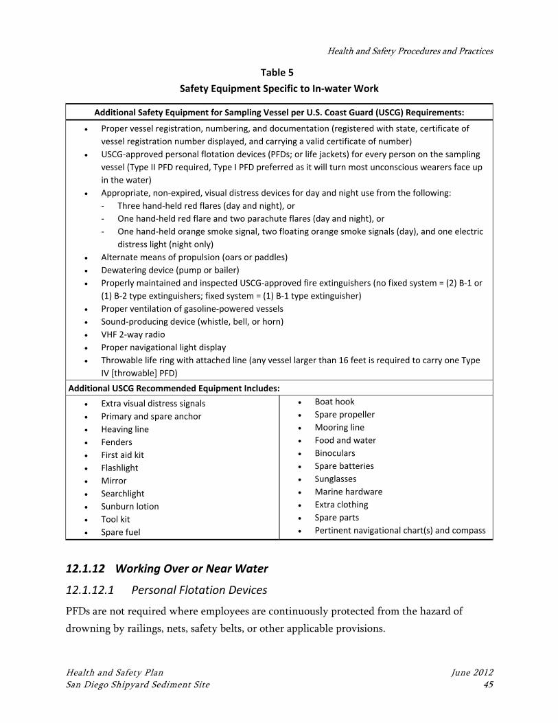
Health and Safety Procedures and Practices
Health and Safety Plan June 2012 San Diego Shipyard Sediment Site 45
Table 5
Safety Equipment Specific to In‐water Work
Additional Safety Equipment for Sampling Vessel per U.S. Coast Guard (USCG) Requirements:
Proper vessel registration, numbering, and documentation (registered with state, certificate of
vessel registration number displayed, and carrying a valid certificate of number)
USCG‐approved personal flotation devices (PFDs; or life jackets) for every person on the sampling
vessel (Type II PFD required, Type I PFD preferred as it will turn most unconscious wearers face up
in the water)
Appropriate, non‐expired, visual distress devices for day and night use from the following:
‐ Three hand‐held red flares (day and night), or
‐ One hand‐held red flare and two parachute flares (day and night), or
‐ One hand‐held orange smoke signal, two floating orange smoke signals (day), and one electric
distress light (night only)
Alternate means of propulsion (oars or paddles)
Dewatering device (pump or bailer)
Properly maintained and inspected USCG‐approved fire extinguishers (no fixed system = (2) B‐1 or
(1) B‐2 type extinguishers; fixed system = (1) B‐1 type extinguisher)
Proper ventilation of gasoline‐powered vessels
Sound‐producing device (whistle, bell, or horn)
VHF 2‐way radio
Proper navigational light display
Throwable life ring with attached line (any vessel larger than 16 feet is required to carry one Type
IV [throwable] PFD)
Additional USCG Recommended Equipment Includes:
Extra visual distress signals
Primary and spare anchor
Heaving line
Fenders
First aid kit
Flashlight
Mirror
Searchlight
Sunburn lotion
Tool kit
Spare fuel
Boat hook
Spare propeller
Mooring line
Food and water
Binoculars
Spare batteries
Sunglasses
Marine hardware
Extra clothing
Spare parts
Pertinent navigational chart(s) and compass
12.1.12 Working Over or Near Water
12.1.12.1 Personal Flotation Devices
PFDs are not required where employees are continuously protected from the hazard of
drowning by railings, nets, safety belts, or other applicable provisions.
Health and Safety Procedures and Practices
Health and Safety Plan June 2012 San Diego Shipyard Sediment Site 46
Type III, Type V, or better USCG-approved International Orange PFD shall be provided and
properly worn by all personnel in the following circumstances:
1. On floating pipelines, pontoons, rafts, or stages.
2. On structures extending over or next to the water, except where guard rails or safety
nets are provided for employees.
3. Working alone at night where there are drowning hazards, regardless of other
safeguards provided.
4. In skiffs, small boats, or launches, unless in an enclosed cabin or cockpit.
5. Whenever there is a drowning hazard.
The following precautions shall be followed when using PFDs:
Prior to and after each use, the buoyant work vests or life preservers shall be
inspected for defects that would alter their strength or buoyancy. Defective devices
or devices with less than 13 pounds buoyancy shall be removed from service.
All PFDs shall be equipped with reflective tape as specified in 46 CFR 25.25-15.
Thirty-inch USCG-approved ring buoys with at least 150 feet of 600-pound capacity
line shall be provided and readily available for emergency rescue operations. The
distance between ring buoys shall not exceed 200 feet.
PFD lights conforming to 46 CFR 161.012 shall be required whenever there is a
potential need for life rings to be used after dark. On shore installations, at least one
life ring, and every third one thereafter, shall have a PFD light attached. PFD lights
on life rings are required only in locations where adequate general lighting (e.g.,
floodlights or light stanchions) is not provided.
12.1.12.2 Cold Water Work
When the water temperature is below 50° F, field personnel working on or near water shall
wear either a float coat and bib-overalls (e.g., a full two-piece “Mustang” survival suit or
similar), or a one-piece survival suit. Suits or float coats shall be USCG approved. If
extremely cold or severe weather conditions are forecast, work activities should be
postponed. Work activities will be continually reviewed and adjustments made if wearing a
survival suit during work activities potentially poses a hazard due to warm air temperatures,
or limited mobility or agility. In addition, proximity of water work to shore and
scope/duration/timing of work activities will be considered when stipulating the above
Health and Safety Procedures and Practices
Health and Safety Plan June 2012 San Diego Shipyard Sediment Site 47
requirement. Overall, if water craft will be used during work, or work will be conducted
near water, it is imperative that site specific conditions are considered and evaluated so that
proper safeguards and procedures are in place prior to beginning work.
In addition to considering the use of apparel appropriate for anticipated air, weather, and
water conditions, field teams shall identify any procedures necessary for cold-water “man-
overboard” scenarios. These procedures should be identified in the site-specific HASP,
described in the JSA used for boating activities and, if prudent, practiced before work.
12.1.13 Noise
Excessive noise is hazardous not only because of its potential to damage hearing, but also
because of its potential to disrupt communications and instructions. The following
procedures and practices shall be followed to prevent noise-related hazards:
All employees will have access to disposable ear plugs with a Noise Reduction Rating
of not less than 30.
Ear plugs must be worn in any environment where workers must raise their voices to
be heard while standing at a distance of 3 feet or less.
Ear plugs must be worn by any personnel operating concrete cutting or sawing
equipment.
Hearing protection is required for workers operating or working near noisy equipment or
operations, where the noise level is greater than 85 A-weighted decibels (dbA) (Time
Weighted Average [TWA]), as well as personnel working around heavy equipment. The FL
will determine the need and appropriate testing procedures, (i.e., sound level meter and/or
dosimeter) for noise measurement.
When needed, a sound level meter will be used to measure noise levels at selected locations
in the work area and on the site perimeter. When used, noise monitoring equipment must
be calibrated before and after each shift.
If continuous noise levels are found to exceed 85 dbA at any location within the work area,
warning signs will be posted. Workers and visitors will be notified that hearing protection is
required. Appropriate hearing protection (i.e., ear plugs or ear muffs) will be worn
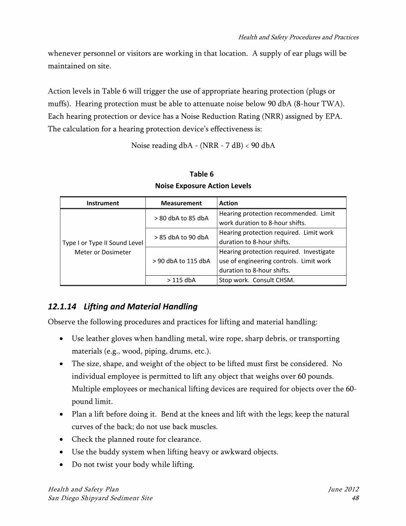
Health and Safety Procedures and Practices
Health and Safety Plan June 2012 San Diego Shipyard Sediment Site 48
whenever personnel or visitors are working in that location. A supply of ear plugs will be
maintained on site.
Action levels in Table 6 will trigger the use of appropriate hearing protection (plugs or
muffs). Hearing protection must be able to attenuate noise below 90 dbA (8-hour TWA).
Each hearing protection or device has a Noise Reduction Rating (NRR) assigned by EPA.
The calculation for a hearing protection device’s effectiveness is:
Noise reading dbA - (NRR - 7 dB) < 90 dbA
Table 6
Noise Exposure Action Levels
Instrument Measurement Action
Type I or Type II Sound Level
Meter or Dosimeter
> 80 dbA to 85 dbA Hearing protection recommended. Limit
work duration to 8‐hour shifts.
> 85 dbA to 90 dbA Hearing protection required. Limit work
duration to 8‐hour shifts.
> 90 dbA to 115 dbA
Hearing protection required. Investigate
use of engineering controls. Limit work
duration to 8‐hour shifts.
> 115 dbA Stop work. Consult CHSM.
12.1.14 Lifting and Material Handling
Observe the following procedures and practices for lifting and material handling:
Use leather gloves when handling metal, wire rope, sharp debris, or transporting
materials (e.g., wood, piping, drums, etc.).
The size, shape, and weight of the object to be lifted must first be considered. No
individual employee is permitted to lift any object that weighs over 60 pounds.
Multiple employees or mechanical lifting devices are required for objects over the 60-
pound limit.
Plan a lift before doing it. Bend at the knees and lift with the legs; keep the natural
curves of the back; do not use back muscles.
Check the planned route for clearance.
Use the buddy system when lifting heavy or awkward objects.
Do not twist your body while lifting.
Health and Safety Procedures and Practices
Health and Safety Plan June 2012 San Diego Shipyard Sediment Site 49
Know the capacity of any handling device (e.g., crane, forklift, chain fall, or come-
along) that you intend to use.
Use tag lines to control loads.
Ensure that your body, material, tools, and equipment are safe from such unexpected
movement as falling, slipping, rolling, tripping, bowing, or any other uncontrolled
motion.
Trucks (i.e., flat beds) hauling equipment or materials must not be moved once
rigging has been released.
Chock all material and equipment (such as pipe, drums, tanks, reels, trailers, and
wagons) as necessary to prevent rolling.
Tie down all light, large-surface-area material that might be moved by the wind.
When working at heights, secure tools, equipment, and wrenches against falling.
Do not store materials or tools on ducts, lighting fixtures, beam flanges, hung ceilings,
or similar elevated locations.
Fuel-powered tools used inside buildings or enclosures shall be vented and checked
for excessive noise.
12.1.15 Fire Control
Observe the following fire control procedures and practices:
Smoke only in designated areas.
Keep flammable liquids in closed containers.
Keep the work site clean; avoid accumulating combustible debris such as paper.
Obtain and follow property owner hot work safety procedures when welding or
performing other activities requiring an open flame.
Isolate flammable and combustible materials from ignition sources.
Ensure fire safety integrity of equipment installations according to National Electrical
Code (NEC) specifications.
12.1.16 Static Electricity and Transfer of Flammable Liquids
Observe the following procedures and practices regarding static electricity when transferring
flammable liquids:
Health and Safety Procedures and Practices
Health and Safety Plan June 2012 San Diego Shipyard Sediment Site 50
Electrically bond and ground pumps, transfer vessels, tanks, drums, bailers, and
probes when moving flammable liquids.
Electrically bond and ground vacuum trucks and the tanks they are emptying.
Do not splash fill containers with flammable liquids.
Pour flammable liquids slowly and carefully.
Two fire extinguishers (2A20:BC) must be available, charged, inspected, and readily
accessible.
12.1.17 Cleaning Equipment
Observe the following procedures and practices when cleaning equipment:
Wear appropriate PPE to avoid skin and eye contact with isopropyl alcohol,
Alconox®, or other cleaning materials.
Stand upwind to minimize any potential inhalation exposure.
Dispose of spent cleaning solutions and rinses accordingly.
12.2 Environmental Hazards and Controls
12.2.1 Heat Stress
Observe the following general procedures and practices regarding heat stress:
Increase the number of rest breaks and/or rotate workers in shorter work shifts.
Watch for signs and symptoms of heat stress and fatigue (see Section 12.2.1.1).
During hot months, plan work for early morning or evening.
Use ice vests when necessary.
Rest in cool, dry areas.
12.2.1.1 Signs, Symptoms, and Treatment
Adverse climatic conditions are important considerations in planning and conducting site
operations. High ambient temperature can result in health effects ranging from transient
heat fatigue, physical discomfort, reduced efficiency, personal illness, and increased accident
probability to serious illness or death. Heat stress is of particular concern when chemical
protective garments are worn since they prevent evaporative body cooling. Wearing PPE
places employees at considerable risk of developing heat stress.
Health and Safety Procedures and Practices
Health and Safety Plan June 2012 San Diego Shipyard Sediment Site 51
Heat stress is caused by a number of interacting factors, including environmental conditions,
clothing, workload, and the individual characteristics of the worker. Because heat stress is
probably one of the most common (and potentially serious) illnesses, regular monitoring and
other preventive precautions are vital.
Heat Rash. Heat rash can be caused by continuous exposure to hot and humid air and skin
abrasion from sweat-soaked clothing, rubber boots, or impermeable waders. The condition is
characterized by a localized red skin rash and reduced sweating. Heat rash reduces the
ability to tolerate heat. To treat, keep skin hygienically clean and allow it to dry thoroughly
after using chemical protective clothing. Take measures to prevent heat rash by changing
clothes often to maximize use of dry garments, or taking frequent breaks to allow doffing of
equipment and drying of skin.
Heat Cramps. Heat cramps are caused by profuse perspiration with inadequate electrolytic
fluid replacement. This often robs the larger muscle groups (stomach and quadriceps) of
blood, which can cause painful muscle spasms and pain in the extremities and abdomen. To
treat, remove the employee to a cool place and give sips of water or an electrolytic drink.
Watch for signs of heat exhaustion or heat stroke.
Heat Exhaustion. Heat exhaustion is a mild form of shock caused by increased stress on
various organs to meet increased demand to cool the body. Onset is gradual and symptoms
should subside within 1 hour. Symptoms include a weak pulse; shallow breathing; pale, cool,
moist skin; profuse sweating; dizziness; and fatigue. To treat, remove the employee to a cool
place and remove as much clothing as possible. Give sips of water or electrolytic solution
and fan the person continuously to remove heat by convection. Do not allow the affected
person to become chilled. Treat for shock if necessary.
Heat Stroke. Heat stroke is the most severe form of heat stress; the body must be cooled
immediately to prevent severe injury and/or death. This is a medical emergency! Symptoms
include red, hot, dry skin; a body temperature of 105° F or higher; no perspiration; nausea;
dizziness and confusion; and a strong, rapid pulse. Since heat stroke is a true medical
emergency, transport the patient to a medical facility immediately. Prior to transport,
remove as much clothing as possible and wrap the patient in a sheet soaked with water. Fan
the patient vigorously while transporting to help reduce body temperature. If available,
Health and Safety Procedures and Practices
Health and Safety Plan June 2012 San Diego Shipyard Sediment Site 52
apply cold packs under the arms, around the neck, or any other place where they can cool
large surface blood vessels. If transportation to a medical facility is delayed, reduce body
temperature by immersing the patient in a cool-water bath (however, be careful not to over-
chill the patient once body temperature is reduced below 102° F). If this is not possible, keep
the patient wrapped in a sheet and continuously douse with water and fan.
12.2.1.2 Prevention
The implementation of preventative measures is the most effective way to limit the effects of
heat-related illnesses. During periods of high heat, adequate liquids must be provided to
replace lost body fluids. Replacement fluids can be a 0.1% saltwater solution, a commercial
mix such as Gatorade, or a combination of these with fresh water. The replacement fluid
temperature should be kept cool, 50° F to 60° F, and should be placed close to the work area.
Employees must be encouraged to drink more than the amount required to satisfy thirst.
Employees should also be encouraged to salt their foods more heavily during hot times of the
year.
Cooling devices such as vortex tubes or cooling vests can be worn beneath impermeable
clothing. If cooling devices are worn, only physiological monitoring will be used to
determine work activity.
All workers are to rest when any symptoms of heat stress are noticed. Rest breaks are to be
taken in a cool, shaded rest area. Employees shall remove chemical protective garments
during rest periods and will not be assigned other tasks.
All employees shall be informed of the importance of adequate rest and proper diet,
including the harmful effects of excessive alcohol and caffeine consumption.
12.2.1.3 Monitoring
Heat stress monitoring should be performed when employees are working in environments
exceeding 90° F ambient air temperature. If employees are wearing impermeable clothing,
this monitoring should begin at 77° F. There are two general types of monitoring that the
health and safety representative can designate to be used: wet bulb globe temperature
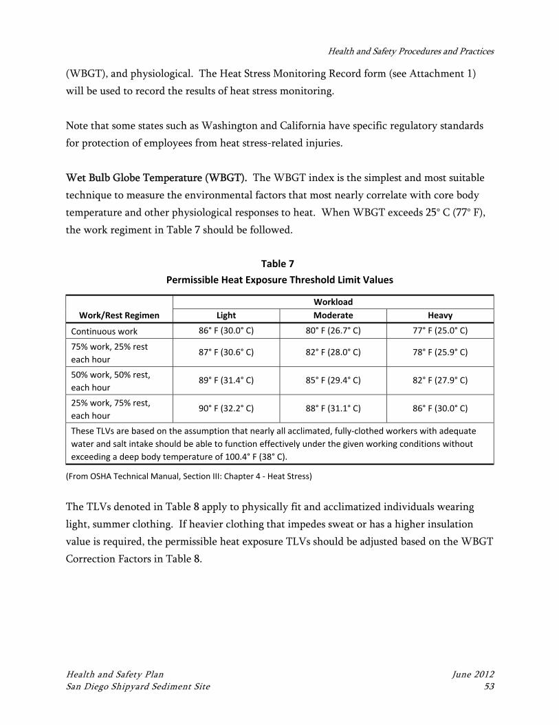
Health and Safety Procedures and Practices
Health and Safety Plan June 2012 San Diego Shipyard Sediment Site 53
(WBGT), and physiological. The Heat Stress Monitoring Record form (see Attachment 1)
will be used to record the results of heat stress monitoring.
Note that some states such as Washington and California have specific regulatory standards
for protection of employees from heat stress-related injuries.
Wet Bulb Globe Temperature (WBGT). The WBGT index is the simplest and most suitable
technique to measure the environmental factors that most nearly correlate with core body
temperature and other physiological responses to heat. When WBGT exceeds 25° C (77° F),
the work regiment in Table 7 should be followed.
Table 7
Permissible Heat Exposure Threshold Limit Values
Work/Rest Regimen
Workload
Light Moderate Heavy
Continuous work 86° F (30.0° C) 80° F (26.7° C) 77° F (25.0° C)
75% work, 25% rest
each hour 87° F (30.6° C) 82° F (28.0° C) 78° F (25.9° C)
50% work, 50% rest,
each hour 89° F (31.4° C) 85° F (29.4° C) 82° F (27.9° C)
25% work, 75% rest,
each hour 90° F (32.2° C) 88° F (31.1° C) 86° F (30.0° C)
These TLVs are based on the assumption that nearly all acclimated, fully‐clothed workers with adequate
water and salt intake should be able to function effectively under the given working conditions without
exceeding a deep body temperature of 100.4° F (38° C).
(From OSHA Technical Manual, Section III: Chapter 4 ‐ Heat Stress)
The TLVs denoted in Table 8 apply to physically fit and acclimatized individuals wearing
light, summer clothing. If heavier clothing that impedes sweat or has a higher insulation
value is required, the permissible heat exposure TLVs should be adjusted based on the WBGT
Correction Factors in Table 8.
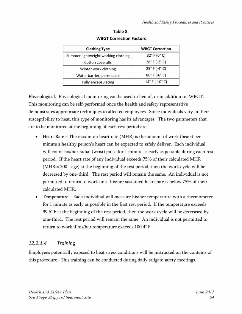
Health and Safety Procedures and Practices
Health and Safety Plan June 2012 San Diego Shipyard Sediment Site 54
Table 8
WBGT Correction Factors
Clothing Type WBGT Correction
Summer lightweight working clothing 32° F (0° C)
Cotton coveralls 28° F (‐2° C)
Winter work clothing 25° F (‐4° C)
Water barrier, permeable 86° F (‐6° C)
Fully encapsulating 14° F (‐10° C)
Physiological. Physiological monitoring can be used in lieu of, or in addition to, WBGT.
This monitoring can be self-performed once the health and safety representative
demonstrates appropriate techniques to affected employees. Since individuals vary in their
susceptibility to heat, this type of monitoring has its advantages. The two parameters that
are to be monitored at the beginning of each rest period are:
Heart Rate – The maximum heart rate (MHR) is the amount of work (beats) per
minute a healthy person’s heart can be expected to safely deliver. Each individual
will count his/her radial (wrist) pulse for 1 minute as early as possible during each rest
period. If the heart rate of any individual exceeds 75% of their calculated MHR
(MHR = 200 - age) at the beginning of the rest period, then the work cycle will be
decreased by one-third. The rest period will remain the same. An individual is not
permitted to return to work until his/her sustained heart rate is below 75% of their
calculated MHR.
Temperature – Each individual will measure his/her temperature with a thermometer
for 1 minute as early as possible in the first rest period. If the temperature exceeds
99.6° F at the beginning of the rest period, then the work cycle will be decreased by
one-third. The rest period will remain the same. An individual is not permitted to
return to work if his/her temperature exceeds 100.4° F
12.2.1.4 Training
Employees potentially exposed to heat stress conditions will be instructed on the contents of
this procedure. This training can be conducted during daily tailgate safety meetings.
Health and Safety Plan June 2012 San Diego Shipyard Sediment Site 55
13 MEDICAL SURVEILLANCE PROGRAM
This section describes the medical surveillance program that Anchor QEA field personnel
must comply with when working on sites where there is a potential for exposure to
hazardous wastes or other hazardous substances.
13.1 General Requirements
Anchor QEA employees shall be enrolled in a medical surveillance program in compliance
with OSHA standards (29 CFR 1910.120(f)) under the following circumstances:
If they are involved with any of the following operations:
Cleanup operations required by a governmental body, whether federal, state, local, or
other involving hazardous substances that are conducted at uncontrolled hazardous
waste sites (including, but not limited to, the EPA’s National Priority List [NPL] sites,
state priority list sites, sites recommended for the EPA NPL, and initial investigation
of government-identified sites that are conducted before the presence or absence of
hazardous substances has been ascertained).
Corrective actions involving cleanup operations at sites covered by the Resource
Conservation and Recovery Act of 1976 (RCRA) as amended (42 U.S.C. 6901 et seq)
Voluntary cleanup operations at sites recognized by federal, state, local, or other
governmental bodies as uncontrolled hazardous waste sites.
Operations involving hazardous wastes that are conducted at treatment, storage, and
disposal (TSD) facilities regulated by 40 CFR Parts 264 and 265 pursuant to RCRA or
by agencies under agreement with the EPA to implement RCRA regulations.
Emergency response operations for releases of, or substantial threats of releases of,
hazardous substances without regard to the location of the hazard.
And, if the employee(s) meets the following criteria:
Are or may be exposed to hazardous substances or health hazards at or above the
established PEL, above the published exposure levels for these substances, without
regard to the use of respirators, for 30 days or more per year.
Medical Surveillance Program
Health and Safety Plan June 2012 San Diego Shipyard Sediment Site 56
In addition, employees are required to be enrolled in the medical surveillance program if
they meet any of the following conditions:
Wear a respirator for 30 days or more per year
Are injured, become ill, or develop signs or symptoms due to possible overexposure
involving hazardous substances or health hazards from an emergency response or
hazardous waste operations
Are members of a Hazardous Materials (HAZMAT) team
Anchor QEA employees required to be enrolled in a medical surveillance program under 29
CFR 1910.120(f) shall have medical examinations and consultations made available to them
by Anchor QEA on the following schedule:
Prior to assignment
At least once every 12 months unless the attending physician believes a longer
interval (not greater than biennially) is appropriate
At termination of employment or reassignment to an area where the employee would
not be covered if the employee has not had an examination within the last 6 months
As soon as possible upon notification that the employee has developed signs or
symptoms indicating possible overexposure to hazardous substances or health hazards,
or that the employee has been injured or exposed above the PEL or published
exposure levels in an emergency situation
At more frequent times, if the examining physician determines that an increased
frequency of examination is medically necessary
The content of medical examinations or consultations made available to employees shall be
determined by the attending physician but shall include, at a minimum, a medical and work
history with special emphasis on symptoms related to the handling of hazardous substances
and health hazards, and to fitness for duty including the ability to wear any required PPE
under conditions (i.e., temperature extremes) that may be expected at the work site.
The attending physician shall provide Anchor QEA with a written opinion for each
examined employee that contains the following information:
Medical Surveillance Program
Health and Safety Plan June 2012 San Diego Shipyard Sediment Site 57
Whether the employee has any detected medical conditions that would place the
employee at an increased risk of impairment of the employee’s health from hazardous
waste operations work, emergency response, or respirator use
Any recommended limitations on the employee’s assigned work
A statement that the employee has been informed of the results of the medical
examination and any medical conditions that require further examination or
treatment
The written opinion obtained by Anchor QEA shall not reveal specific findings or diagnoses
unrelated to occupational exposures. Medical surveillance and other employee-related
medical records shall be retained for at least the duration of employment plus 30 years.
13.2 Crew Self Monitoring
All personnel will be instructed to look for and inform each other of any deleterious changes
in their physical or mental condition during the performance of all field activities. Examples
of such changes are as follows:
Headaches
Dizziness
Nausea
Blurred vision
Cramps
Irritation of eyes, skin, or respiratory system
Changes in complexion or skin color
Changes in apparent motor coordination
Increased frequency of minor mistakes
Excessive salivation or changes in papillary response
Changes in speech ability or speech pattern
Symptoms of heat stress or heat exhaustion
Symptoms of hypothermia
If any of these conditions develop, the affected person will be moved from the immediate
work location and evaluated. If further assistance is needed, personnel at the local hospital
will be notified, and an ambulance will be summoned if the condition is thought to be
Medical Surveillance Program
Health and Safety Plan June 2012 San Diego Shipyard Sediment Site 58
serious. If the condition is the result of sample collection or processing activities, procedures
and/or PPE will be modified to address the problem.
ATTACHMENT 1 HEALTH AND SAFETY LOGS AND FORMS
March 2012 1
Anchor QEA
Release from Liability, Waiver of Claims, and Indemnification
READ CAREFULLY BEFORE SIGNING ** This liability release, waiver, and indemnification is required for participation in our
field trips and site tours** ** Each participant must sign his/her own form **
In return for receiving permission from Anchor QEA, LLC, a Washington State limited liability corporation ("Anchor QEA") to participate in the field trip which is to take place at (location) on (date) (collectively, the "Activities"), the undersigned participant (“Participant”), acting through and/or with the consent of his/her parent or legal guardian (if Participant is a minor or the subject of a guardianship), hereby agrees as follows:
1. I fully recognize the dangers of participating in the Activities, and I voluntarily assume all risks associated with my participation in the Activities. I understand that the dangers which I may encounter at the site(s) where the Activities take place (in each case, a “Site”) include, by way of example only and without limitation: exposure to contaminants; exposure to aerosol vapors; wild animals, poisonous snakes and harmful insects; poisonous vegetation; drowning, sea sickness and boating accidents; falling from steep slopes, cliffs or narrow trails; landslides; rough terrain; lightning; wildfire; extremes of temperatures; and storms. I realize that there is also a risk of my becoming seriously ill or injured in an area remote from medical care and that Anchor QEA cannot guarantee the availability of emergency medical services or emergency transportation to medical facilities.
2. I agree that neither Anchor QEA nor any of its agents, representatives, partners, contractors, consultants or employees: (a) shall have any liability for any defect or dangerous natural or artificial condition relating to any Site or any of the Activities; or (b) have made or are making any representation or warranty, expressed or implied, regarding: (i) the conditions of any Site; (ii) the safety of the Activities or any of the equipment to be used in connection with the Activities; (iii) any means of transportation to or from any Site; or (iv) any other aspect of any Site or any of the Activities.
Release from Liability, Waiver of Claims, and Indemnification
March 2012 Liability Waver 2
3. I agree to take the responsibility to familiarize myself with the rules and regulations applicable to the Sites and the Activities, and to ensure that I have been properly instructed in and understand the use of any equipment I am to use in the Activities. I realize that my participation in the Activities may require sustained strenuous physical activity. I am in good health, and am not aware of any physical or medical condition that might endanger myself or other participants in the Activities.
4. Acting for myself and my heirs, executors, personal representatives and assigns, I forever release and discharge Anchor QEA and its owners, employees, agents, officers, and directors, and the successors and assigns of each of them (in each case, a “Released Party"), of and from all claims, losses, damages, costs, expenses and other liabilities, including (but not limited to) reasonable attorneys' fees (in each case, a "Claim"), whether known or unknown, foreseen or unforeseen, relating to property damage or the death, injury, pain or mental trauma of myself or any other person, and resulting, directly or
indirectly, from my participation in the Activities or my travel to or from any Site. Without limiting the above, I agree not to sue any of the Released Parties for any such Claims, to waive any such Claims which I may have at any time against any of the Released Parties, and to indemnify and defend each of the Released Parties against, and to hold each of the Released Parties harmless of and from any Claims resulting from my acts or omissions during the Activities or while at any Site.
5. I have read and understand the policies and procedures specified in the Health and Safety Plan (HASP) for this site. This HASP may include company-specific appendices developed by entities other than Anchor QEA. The undersigned Participant acknowledges and agrees that he/she has carefully read this Release from Liability, Waiver of Claims, and Indemnification and fully understands all of its contents, and their legal effect, and agrees that this Release from Liability, Waiver of Claims, and Indemnification (of which I have been given a copy to keep, with any attachments) is contractually binding, and is being signed by the undersigned Participant of his/her own free will. Signature: Date: Printed Name: Email: Address:

Release from Liability, Waiver of Claims, and Indemnification
March 2012 Liability Waver 3
(street address – no PO Boxes) City: State: ZIP: Phone Number: Emergency Contact: Contact’s Phone Number:
Consent and Release for Publications of Photographs
I, the undersigned, hereby grant Anchor QEA permission to take photographs of me, and irrevocably consent to and authorize the use and reproduction by Anchor QEA, or anyone duly authorized by Anchor QEA, of any and all such photographs, for any legitimate purposes, including for advertising, trade, and editorial purposes, at any time in the future in all media now known or hereafter developed, throughout the world. I also consent to the use of my name in connection with such photos. I hereby release, indemnify, and hold harmless Anchor QEA and its owners, officers, directors, agents, and employees from any and all claims which may result at any time by reason of the use of my image and name, including, without limitation, claims of privacy. My heirs, executors, administrators, and assigns shall be bound by this consent and release. I am over the age of 18. Signature: Date: Printed Name:
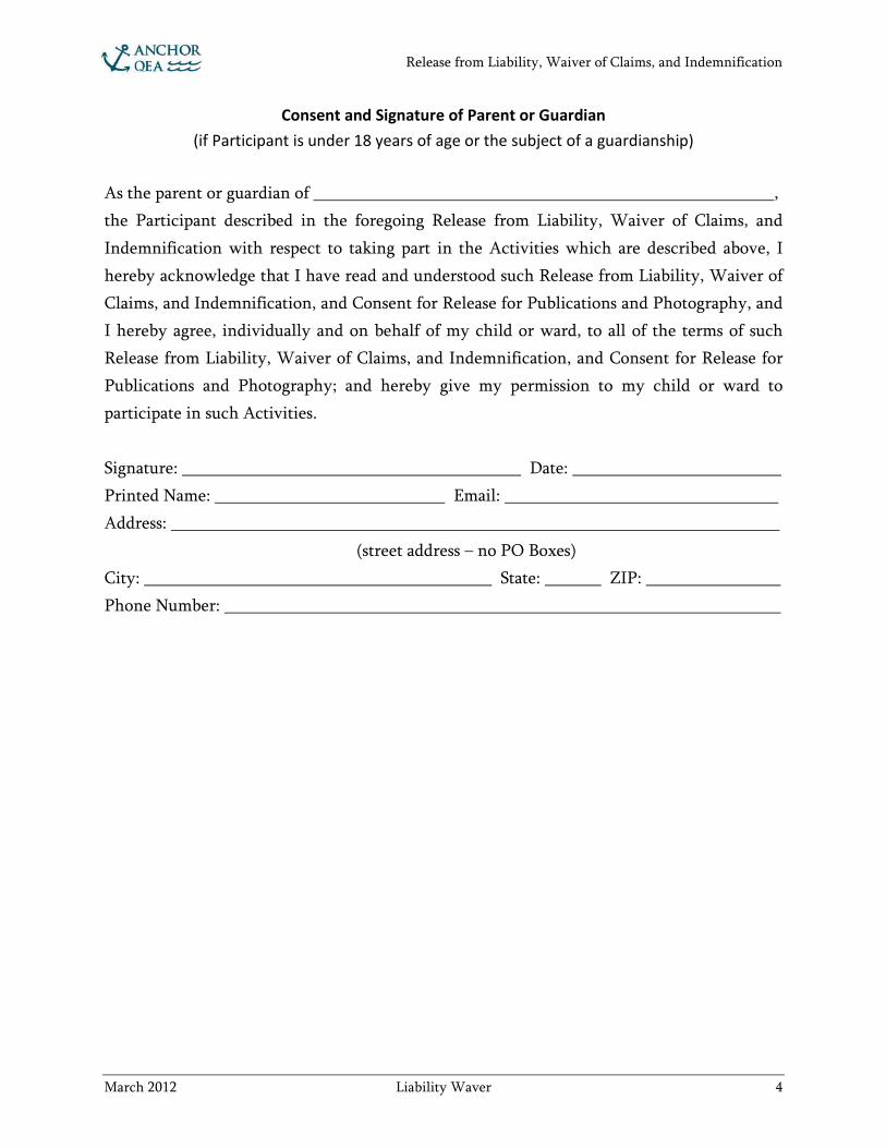
Release from Liability, Waiver of Claims, and Indemnification
March 2012 Liability Waver 4
Consent and Signature of Parent or Guardian (if Participant is under 18 years of age or the subject of a guardianship)
As the parent or guardian of , the Participant described in the foregoing Release from Liability, Waiver of Claims, and Indemnification with respect to taking part in the Activities which are described above, I hereby acknowledge that I have read and understood such Release from Liability, Waiver of Claims, and Indemnification, and Consent for Release for Publications and Photography, and I hereby agree, individually and on behalf of my child or ward, to all of the terms of such Release from Liability, Waiver of Claims, and Indemnification, and Consent for Release for Publications and Photography; and hereby give my permission to my child or ward to participate in such Activities. Signature: Date: Printed Name: Email: Address: (street address – no PO Boxes) City: State: ZIP: Phone Number:
DATE: PROJECT NAME:
PROJECT NUMBER: HEAT STRESS MONITORING RECORD LOCATION:
1 of 1
Employee Name
Monitoring Results Initial Reading
Time: First Work
Period Time: Second Work Period Time:
Third Work Period Time:
Fourth Work Period Time:
Fifth Work Period Time:
Sixth Work Period Time:
WBGT (°F): WBGT (°F): WBGT (°F): WBGT (°F): WBGT (°F): WBGT (°F): WBGT (°F):
Air Temp (°F): Air Temp (°F): Air Temp (°F): Air Temp (°F): Air Temp (°F): Air Temp (°F): Air Temp (°F):
Initial Temp: Initial Temp: Final Temp: Initial Temp: Final Temp: Initial Temp: Final Temp: Initial Temp: Final Temp: Initial Temp: Final Temp: Initial Temp: Final Temp:
Initial H.R.: Initial H.R.: Final H.R.: Initial H.R.: Final H.R.: Initial H.R.: Final H.R.: Initial H.R.: Final H.R.: Initial H.R.: Final H.R.: Initial H.R.: Final H.R.:
Notes: Completed by:
Printed Name Signature Date
UTILITY CONTACT PREVENTION CHECKLIST
NOTE: Utility mark-out requirements vary from state to state; consult state authorities before work.
1 of 2
Purpose: This form is intended to help the Field Lead confirm that underground or overhead utilities are identified to the extent practicable and consistent with applicable regulations prior to site work. PROJECT NAME/NO: DATE: FIELD LEAD: STATE: PROJECT MANAGER: HEALTH & SAFETY OFFICER: EMERGENCY CONTACT INFORMATION FOR ONE-CALL: DURATION/SUMMARY OF WORK TO BE PERFORMED:
Consideration Check Explanation Initial
Has the state one-call been contacted? Yes No Has the property owner or client been contacted for local knowledge of utilities, as applicable?
Yes No
Are any as-built drawings available? If so, do they show any utilities?
Yes No
Has a visual inspection of the work area(s) been completed?
Yes No
Has a private locating service been contacted? Yes No Were any utilities identified and marked out through private locating service? If so, duplicate mark outs on site drawings.
Yes No
Are there any fiber optic cables, fuel lines, or high pressure lines within 50 feet of hole locations?
Yes No
If fiber optic cables, fuel lines, or high pressure lines are within 50 feet has an agreement with the utility owner been established, if applicable?
Yes No
Can a test borehole be advanced by hand digging, probing, post hole digging, and/or air knifed to 5 feet below ground surface (bgs)?
Yes No
If hand digging, probing, post hole digging, and or air knifing to 5 feet bgs is not possible, can a non-invasive geophysical investigation be conducted? If not, why?
Yes No
Other considerations:
NOTE: Please fill in second page and attach additional reports, drawings, or other information as necessary.
UTILITY CONTACT PREVENTION CHECKLIST
NOTE: Utility mark-out requirements vary from state to state; consult state authorities before work.
2 of 2
CONFIRMATION NUMBER: CONTACT NAME: ORGANIZATION: CONTACT DATE: CONTACT TIME: RESPONSE: Completed by:
Printed Name Signature Date Contractor:
Printed Name Signature Date
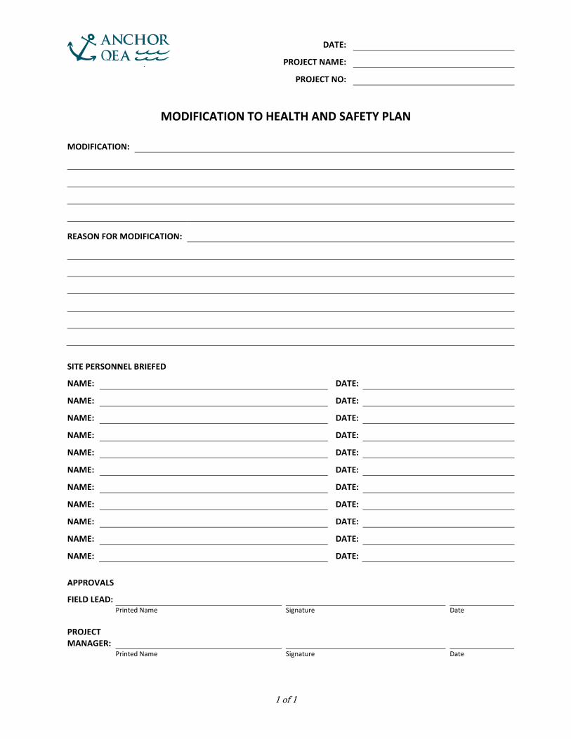
DATE:
PROJECT NAME: PROJECT NO:
MODIFICATION TO HEALTH AND SAFETY PLAN
1 of 1
MODIFICATION: REASON FOR MODIFICATION: SITE PERSONNEL BRIEFED
NAME: DATE: NAME: DATE: NAME: DATE: NAME: DATE: NAME: DATE: NAME: DATE: NAME: DATE: NAME: DATE: NAME: DATE: NAME: DATE: NAME: DATE: APPROVALS
FIELD LEAD: Printed Name Signature Date PROJECT MANAGER: Printed Name Signature Date

DATE:
PROJECT NAME: PROJECT NO:
DAILY SAFETY BRIEFING
1 of 1
PERSON CONDUCTING HEALTH & SAFETY PROJECT MEETING: OFFICER: MANAGER: TOPICS COVERED:
Emergency Procedures and Evacuation Route
Lines of Authority Lifting Techniques Directions to Hospital Communication Slips, Trips, and Falls HASP Review and Location Site Security Hazard Exposure Routes Safety Equipment Location Vessel Safety Protocols Heat and Cold Stress Proper Safety Equipment Use Work Zones Overhead and Underfoot Hazards Employee Right-to-Know/MSDS Location
Vehicle Safety and Driving/Road Conditions
Chemical Hazards Fire Extinguisher Location Equipment Safety and Operation Flammable Hazards Eye Wash Station Location Proper Use of PPE Biological Hazards Buddy System Decontamination Procedures Eating/Drinking/Smoking Self and Coworker Monitoring Other:
WEATHER CONDITIONS: ATTENDEES
PRINTED NAME SIGNATURE
DAILY WORK SCOPE: SITE-SPECIFIC HAZARDS: SAFETY COMMENTS:
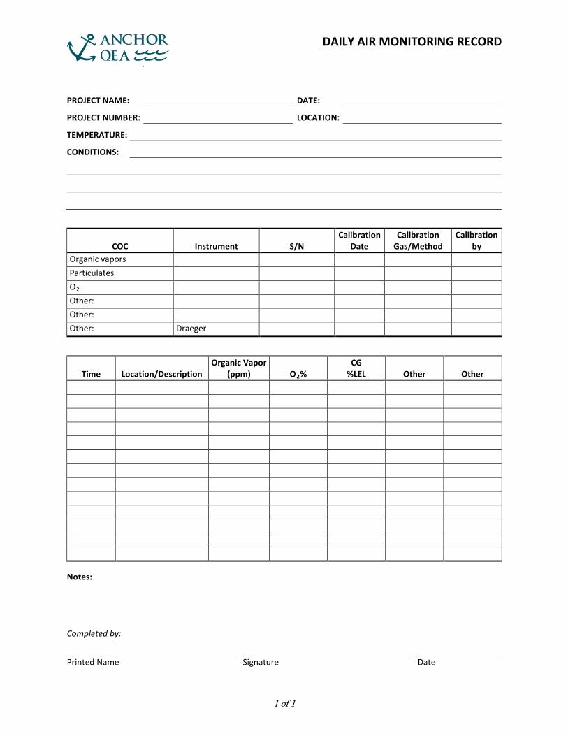
DAILY AIR MONITORING RECORD
1 of 1
PROJECT NAME: DATE: PROJECT NUMBER: LOCATION: TEMPERATURE: CONDITIONS:
COC Instrument S/N Calibration
Date Calibration
Gas/Method Calibration
by Organic vapors Particulates O2 Other: Other: Other: Draeger
Time Location/Description Organic Vapor
(ppm) O2% CG
%LEL Other Other
Notes: Completed by:
Printed Name Signature Date
ATTACHMENT 2 JOB SAFETY ANALYSIS (JSA) DOCUMENTS
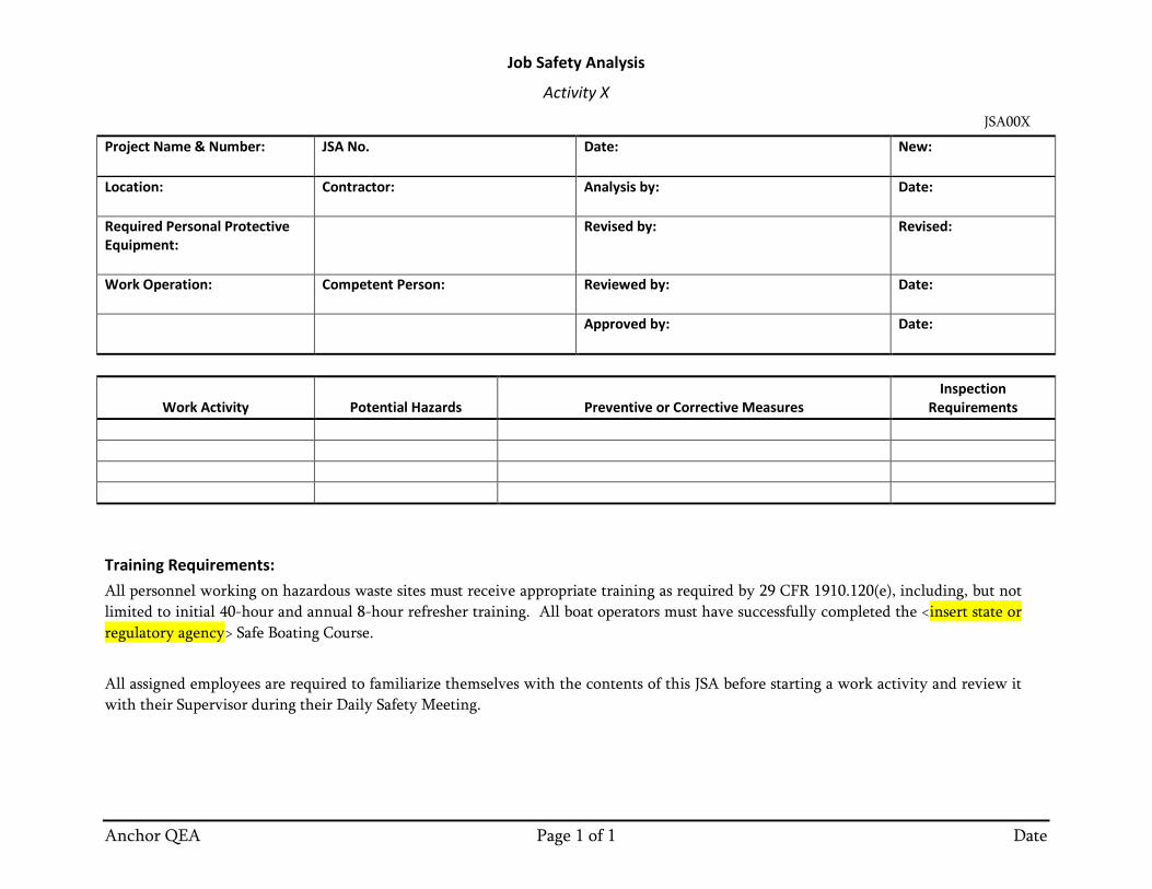
Job Safety Analysis
Activity X
JSA00X
Anchor QEA Page 1 of 1 Date
Project Name & Number:
JSA No.
Date:
New:
Location:
Contractor:
Analysis by:
Date:
Required Personal Protective Equipment:
Revised by:
Revised:
Work Operation:
Competent Person:
Reviewed by:
Date:
Approved by:
Date:
Work Activity Potential Hazards Preventive or Corrective Measures Inspection
Requirements
Training Requirements: All personnel working on hazardous waste sites must receive appropriate training as required by 29 CFR 1910.120(e), including, but not limited to initial 40-hour and annual 8-hour refresher training. All boat operators must have successfully completed the <insert state or regulatory agency> Safe Boating Course. All assigned employees are required to familiarize themselves with the contents of this JSA before starting a work activity and review it with their Supervisor during their Daily Safety Meeting.
ATTACHMENT 3 MATERIAL SAFETY DATA SHEETS (MSDS)


![APPENDIX E NOISE IMPACT ANALYSIS · San Diego Ship Repair Facility [BAE Systems] and the National Steel and Shipbuilding Company Shipyard Facility [NASSCO]). The Shipyard Sediment](https://static.fdocuments.in/doc/165x107/60400ac6b9b70502aa5dd8a5/appendix-e-noise-impact-analysis-san-diego-ship-repair-facility-bae-systems-and.jpg)