REMEDIAL ACTION CONTRACT
230
REMEDIAL ACTION CONTRACT United States Environmental Protection Agency Region 6 Contract No. EP-W-06-021 Treatability Test Plan Version 2.1 American Creosote Works Site Feasibility Study Winnfield, Louisiana Task Order No. 0051-RIFS-06G3 Document Control No. 0051-02008 November 2011 In Association With: Weston Solutions E2 Consulting Engineers, Inc. Arrowhead Contracting, Inc. 007132
Transcript of REMEDIAL ACTION CONTRACT
REMEDIAL ACTION CONTRACT
United States Environmental Protection Agency Region 6
Contract No. EP-W-06-021
Treatability Test Plan Version 2.1
American Creosote Works Site
Feasibility Study Winnfield, Louisiana
Task Order No. 0051-RIFS-06G3 Document Control No. 0051-02008
November 2011
In Association With: Weston Solutions E2 Consulting Engineers, Inc. Arrowhead Contracting, Inc.
007132

AMERICAN CREOSOTE WORKS SITE FEASIBILITY STUDY TREATABILITY TEST PLAN
VERSION 2.1
ACW_TTP_VER2.1.DOCX NOVEMBER 2011 ES111011092113DFW
(This page intentionally left blank)
007133
ACW_TTP_VER2.1.DOCX NOVEMBER 2011 ES111011092113DFW
V e r s i o n 2 . 1
American Creosote Works Site Feasibility Study
Treatability Test Plan
Prepared for
U.S. Environmental Protection Agency
Contract No. EP-W-06-021 Task Order 0051-RIFS-06G3
CH2M HILL Project No. 411242 DCN 0051-02008
November 2011
12750 Merit Drive Suite 1100
Dallas, Texas 75251
007134

AMERICAN CREOSOTE WORKS SITE FEASIBILITY STUDY TREATABILITY TEST PLAN
VERSION 2.1
ACW_TTP_VER2.1.DOCX NOVEMBER 2011 ES111011092113DFW
(This page intentionally left blank)
007135
ACW_TTP_VER2.1.DOCX v NOVEMBER 2011 ES111011092113DFW
Preface
The U.S. Environmental Protection Agency (EPA) Region 6 has retained CH2M HILL under Remedial Action Contract No. EP-W-06-021, Task Order No. 0051, to perform treatability study (TS) activities in support of the Feasibility Study (FS) for the American Creosote Works (ACW) Superfund Site (Site) in Winnfield, Louisiana. As part of this effort, site-specific planning documents are required to provide the detail necessary to implement the associated fieldwork. The site-specific planning documents consist of the following six separately bound documents:
Field Operations Plan (FOP) (CH2M HILL, 2006a) Quality Assurance Project Plan (QAPP) (CH2M HILL, 2011a) Site Management Plan (SMP) (CH2M HILL, 2006b) Transportation and Disposal Plan (TDP) (CH2M HILL, 2006c) Health and Safety Plan (HSP) (CH2M HILL, 2010a) Treatability Test Plan (TTP) - This document
The FOP provides detailed methods and procedures to be used during implementation of the field activities. The QAPP provides quality assurance/quality control requirements to ensure that the data obtained are suitable for their intended purpose. The SMP provides detailed procedures for site access, site security, traffic and noise control, and management of investigation-derived waste (IDW) to be followed during implementation of the TS field activities. The HSP provides health and safety procedures to be followed during implementation of the TS field activities and a HSP Addendum describing tasks specific to the treatability testing (TT) has been included as Appendix A. The TDP provides information regarding the labeling, storage, transportation, and disposal of IDW.
This TTP provides detailed procedures for three TS tests: (1) in situ chemical oxidation (ISCO), (2) surfactant-enhanced product recovery (S-EPR), and (3) in situ solidification/ stabilization (ISS). The first two tests will be conducted at the field scale while the third test will be performed as a bench-scale test. Bench-scale testing of the S-EPR technology was performed previously as described in the Engineering Optimization/Treatability Study for the American Creosote Works Superfund Site, City of Winnfield, Winn Parish, Louisiana (VeruTEK, 2008). This TTP serves as the primary site-specific plan, supported by the other documents listed above.
007136

PREFACE
ACW_TTP_VER2.1.DOCX vi NOVEMBER 2011 ES111011092113DFW
(This page intentionally left blank)
007137
ACW_TTP_VER2.1.DOCX vii NOVEMBER 2011 ES111011092113DFW
Contents
Section Page
Preface ................................................................................................................................................... v
Contents ............................................................................................................................................. vii
Abbreviations and Acronyms ......................................................................................................... ix
1 Project Description ............................................................................................................. 1-1
1.1 Purpose .................................................................................................................... 1-1 1.2 Site Background ...................................................................................................... 1-1
1.2.1 Facility Description and History ............................................................. 1-1 1.2.2 Conceptual Site Model .............................................................................. 1-2 1.2.3 Long-term Treatment Goals ..................................................................... 1-6 1.2.4 Treatability Testing Technology Demonstration Areas ....................... 1-7
2 Treatment Technology Description ................................................................................ 2-1
2.1 In Situ Chemical Oxidation ................................................................................... 2-1 2.1.1 Key Uncertainties ...................................................................................... 2-2
2.2 S-EPR ........................................................................................................................ 2-3 2.2.1 Key Uncertainties ...................................................................................... 2-3
2.3 In Situ Solidification/Stabilization ...................................................................... 2-3 2.3.1 Key Uncertainties ...................................................................................... 2-4
3 Test Objectives .................................................................................................................... 3-1
3.1 Step 1 – State the Problem ..................................................................................... 3-1 3.2 Step 2 – Identify the Goals of the Study .............................................................. 3-2 3.3 Step 3 – Identify Information Input ..................................................................... 3-3 3.4 Step 4 – Define the Boundaries of the Study ...................................................... 3-3 3.5 Step 5 – Develop the Analytic Approach ............................................................ 3-4 3.6 Step 6 – Specify Performance or Acceptance Criteria ....................................... 3-5 3.7 Step 7 – Plan for Obtaining Data .......................................................................... 3-5
4 Experimental Design and Procedures ............................................................................ 4-1
4.1 Pre-test Mobilization Activities ............................................................................ 4-1 4.2 Baseline Sampling and Well Rehabilitation ........................................................ 4-2
4.2.1 Baseline Sampling ..................................................................................... 4-2 4.2.2 Well Rehabilitation .................................................................................... 4-5
4.3 Technology Testing ................................................................................................ 4-6 4.3.1 ISCO ............................................................................................................ 4-6 4.3.2 S-EPR ........................................................................................................... 4-6 4.3.3 Demobilization ........................................................................................ 4-10 4.3.4 ISS .............................................................................................................. 4-10
4.4 Field Test Performance Sampling ...................................................................... 4-14 4.4.1 ISCO .......................................................................................................... 4-17 4.4.2 S-EPR ......................................................................................................... 4-17
007138
CONTENTS
ACW_TTP_VER2.1.DOCX viii NOVEMBER 2011 ES111011092113DFW
4.4.3 PLTS Effluent ........................................................................................... 4-17
5 Data Analysis and Interpretation .................................................................................... 5-1
5.1 ISCO and S-EPR Pilot-Scale Tests ........................................................................ 5-1 5.2 ISS Bench-scale Test ............................................................................................... 5-1
6 Reports .................................................................................................................................. 6-1
7 Schedule ............................................................................................................................... 7-1
8 Works Cited ......................................................................................................................... 8-1
Tables
1-1 Recovered Creosote (NAPL) Characteristics 1-2 Comparison of ROD Remedial Goals with Proposed PRGs for Selected
Contaminants 4-1 Baseline Sampling Requirements 4-2 S-EPR Pilot Study Process 4-3 ISS Bench-Scale Test Analyses 4-4 Performance Sampling Requirements
Figures
1-1 Facility Map 1-2 Current Site Map – December 2009 1-3 Conceptual Hydrogeologic Model 1-4 Free-Phase Oil Distribution in Shallow Aquifer 1-5 Treatment Area Locations 4-1 Treatment Area 1 4-2 Treatment Area 2
Appendixes
A Health and Safety Plan Addendum B Soil and Groundwater Sampling Procedures C Capacity Test SOP D Project Schedule
007139
ACW_TTP_VER2.1.DOCX ix NOVEMBER 2011 ES111011092113DFW
Abbreviations and Acronyms
ACW American Creosote Works
BaP benzo(a)pyrene
bgs below ground surface
BTEX benzene, toluene, ethylbenzene, and xylenes
CHP catalyzed hydrogen peroxide
cm/sec centimeter per second
CO2 carbon dioxide
COC contaminant of concern
DNAPL dense nonaqueous phase liquid
DQO data quality objective
EPA U.S. Environmental Protection Agency
ERGI Evergreen Resources Group, Inc.
FOP Field Operations Plan
FS feasibility study
GCI Geo-Cleanse International, Inc.
HSP health and safety plan
IDW investigation-derived waste
ISCO in situ chemical oxidation
ISS in situ solidification/stabilization
kg kilogram
L liter
LDEQ Louisiana Department of Environmental Quality
µg/kg microgram per kilogram
µg/L microgram per liter
mg/kg milligram per kilogram
MCL maximum contaminant level
ml milliliter
007140
ABBREVIATIONS AND ACRONYMS
ACW_TTP_VER2.1.DOCX x NOVEMBER 2011 ES111011092113DFW
NAPL nonaqueous phase liquid
oz ounce
PAH polycyclic aromatic hydrocarbon
PCP pentachlorophenol
PLTS process liquid treatment system
psi pound per square inch
PRG preliminary remedial goal
PTD Prairie Terrace deposits
QAPP quality assurance project plan
RI remedial investigation
ROD Record of Decision
ROI radius of influence
S-EPR surfactant-enhanced product recovery
SVOC semivolatile organic compound
SARA Superfund Amendments and Reauthorization Act of 1986
Site American Creosote Works Superfund Site
SMP site management plan
SPLP synthetic precipitation leaching procedure
TDP transportation and disposal plan
TMV toxicity, mobility, and volume
TOC total organic carbon
TPH total petroleum hydrocarbon
TS treatability study
TTP treatability test plan
TT treatability testing
UCS unconfined compressive strength
VOA volatile organic analysis
VOC volatile organic compound
007141
ACW_TTP_VER2.1.DOCX 1-1 NOVEMBER 2011 ES111011092113DFW
SECTION 1
Project Description
This Treatability Test Plan (TTP) has been prepared for the U.S. Environmental Protection Agency (EPA) Region 6 under Remedial Action Contract No. EP-W-06-021, Task Order No. 0051. This TTP describes treatability study (TS) activities to be performed in support of the Feasibility Study (FS) for the American Creosote Works (ACW) Superfund Site (Site) in Winnfield, Louisiana.
1.1 Purpose Under the Superfund Amendments and Reauthorization Act of 1986 (SARA), EPA is required to select remedial actions involving treatment that permanently and significantly reduce the toxicity, mobility, and volume (TMV) of the hazardous substances present at a site. Uncertainties associated with respect to the performance, reliability, and cost of treatment technologies, especially those that may be innovative, underscore the need for treatability studies during the FS. Treatability studies provide valuable site-specific data necessary to support Superfund remedial actions. They serve two primary purposes: (1) to aid in the selection of the remedy, and (2) to aid in the implementation of the selected remedy.
This TTP provides detailed procedures that will be used to test three different technologies for treatment of creosote-contaminated soil and groundwater. The three technologies include: (1) in situ chemical oxidation (ISCO), (2) surfactant-enhanced product recovery (S-EPR), and (3) in situ solidification/stabilization (ISS). The first two technologies will be tested at the field scale, while the third will use a bench-scale approach. The findings from the TTP will be used to determine if these technologies should be retained as a component(s) of a site-wide remedial alternative to be evaluated in the FS, and if so, to develop conceptual design and cost estimate information to support the detailed and comparative evaluation of alternatives in the FS.
This document, together with the Field Operations Plan (FOP) (CH2M HILL, 2006a) and the Quality Assurance Project Plan (QAPP) (CH2M HILL, 2011a), provides the sampling and analysis instruction necessary to carry out the TS. The TTP will also be used in conjunction with the Site Management Plan (SMP) (CH2M HILL, 2006b), Transportation and Disposal Plan (TDP) (CH2M HILL, 2006c), and the Health and Safety Plan (HSP) (CH2M HILL, 2010a), each provided separately, to fully execute all elements of this work. An addendum to the HSP is provided in Appendix A.
1.2 Site Background 1.2.1 Facility Description and History The Site (see Figure 1-1) is a 34-acre former wood treating facility that used creosote and pentachlorophenol (PCP) to treat various wood products between 1901 and 1984. The facility (Comprehensive Environmental Response, Compensation, and
007142

SECTION 1: PROJECT DESCRIPTION
ACW_TTP_VER2.1.DOCX 1-2 NOVEMBER 2011 ES111011092113DFW
Liability Information System [CERCLIS] No. LAD000239814) was placed on the EPA’s National Priorities List in 1992 and has undergone extensive remediation since the Record of Decision (ROD) was signed in April 1993 (EPA, 1993). CH2M HILL is currently operating a fluids extraction and in situ bioremediation system to treat the subsurface soil and groundwater contamination remaining at the Site. This system comprises 28 recovery wells and trench sumps, several injection wells and injection trenches, an onsite process liquid treatment system (PLTS), and an extensive array of underground piping to convey fluids to and from the PLTS (see Figure 1-2). The PLTS includes an oil-water separator and lamella clarifier for free-phase and emulsified oil removal, and biological and granular activated carbon for dissolved-phase contaminant treatment.
In addition to installation of the PLTS, remedial actions completed at the Site to date include incineration of highly contaminated material present in the former Tar Mat Area with burial of the incinerator ash in an onsite geotextile-lined, clay-covered cell identified as the Tar Mat Ash Disposal Area, and consolidation of 7,000 cubic yards of low-level contaminated soil with material stabilized during pre-ROD removal actions in a waste cell (see Figure 1-2). The waste cell is covered with 1 to 3 feet of clay and underlain with a visqueen-plastic liner. The soil incineration and consolidation actions were completed in 1995. The deep subsurface soil and groundwater component of the remedy, including the PLTS, was implemented in October 1996. Through September 2010, the deep subsurface soil and groundwater remedy has recovered approximately 196,000 gallons of free-phase and emulsified creosote and treated 80 million gallons of groundwater.
1.2.2 Conceptual Site Model Complete details of the conceptual site model can be found in the Subsurface Investigation Report (CH2M HILL, 2008).
Hydrogeologic Setting The primary geologic strata underlying the Site include, in descending order, fill material, the Prairie Terrace deposits (PTD), and the Cockfield Formation. The fill material comprises primarily 1 to 3 feet of silty-clay that was placed over large portions of the Site during remedial construction. In other portions of the Site that were disturbed by historical site activities, clayey-gravelly fill extends to depths between 3 and 8 feet.
The PTD, also referred to as the shallow aquifer, comprises a clay, silt, and fine sand mixture that forms a semiwedge beneath the Site (see Figure 1-3). The thickness of the PTD ranges from 20 to 37 feet, and the depth to groundwater typically averages 8 feet below ground surface (bgs). Under natural (non-pumping) conditions, groundwater flows radially outward from the south end of the Site to the west and north where it enters Creosote Branch Creek, a groundwater flow boundary. A majority of the soil and groundwater contamination at the Site occurs within the PTD.
The Cockfield Formation lies beneath the PTD and is informally referred to as the deep aquifer. This unit is characterized as an interbedded clay, silt, and sand with some lignite (organic material). In the central and northern portions of the Site, the contact between the PTD and Cockfield Formation is marked by the presence of pebble gravel and a transition to a very dense, fine- to medium-grade sand with thin beds of lignite. At the south end of the Site, a thin bed of pink clay was observed at the contact between the PTD and Cockfield
007143
SECTION 1: PROJECT DESCRIPTION
ACW_TTP_VER2.1.DOCX 1-3 NOVEMBER 2011 ES111011092113DFW
Formation. The Cockfield Formation outcrops at the south end of the Site in the vicinity of the pond and extends to depths of at least 65 feet in some areas.
Groundwater occurs in the Cockfield Formation. Under non-pumping conditions, groundwater flows radially outward from the south to the west and northeast. Groundwater elevations in the Cockfield Formation are, on average, about 8 feet higher than present in the overlying PTD resulting in an upward vertical hydraulic gradient. It is unknown if Creosote Branch Creek represents a groundwater flow boundary for the deep aquifer.
Given the apparent absence of a laterally contiguous silt or clay unit between the PTD and Cockfield Formation, and presence of an upward vertical hydraulic gradient, it is presumed that groundwater moves freely from the Cockfield Formation to the overlying PTD.
Contaminant Sources Releases of creosote and PCP wood-treating oil during the facility’s 80-year history resulted in extensive subsurface soil and groundwater contamination at the Site. From information compiled during the 1991 to 1992 remedial investigation (RI)/FS) (CDM, 1992), it was determined that wood treating operations occurred in a process area located in the north-central portion of the Site.
A tank farm with no visible secondary containment was also located near the process area. The earliest site photographs (1940 and 1947) provided visual evidence (soil staining and stressed vegetation) that wood treating oil flowed unimpeded from the process area toward Creosote Branch Creek. A surface drainage pathway that discharged to Creosote Branch Creek is visible on a 1940 aerial photograph.
Four unlined impoundments (see Figure 1-2) received liquid wood-treating process wastes that reportedly contained water, tree sap, creosote, petroleum distillates, and PCP (CDM, 1992).
Wood treating oil released to the ground surface and liquid waste placed in the unlined impoundments infiltrated into the subsurface where it now resides as a separate, nonaqueous phase liquid (NAPL) residual (immobile) phase within the soil column, and as a free (mobile)-phase NAPL pooled at the base of the PTD. The soluble organic compounds present in the oil dissolve into shallow aquifer groundwater, resulting in the formation of a plume that is transported toward Creosote Branch Creek.
Preliminary evaluation of data obtained from a comprehensive re-baseline investigation performed in January and February 2008 indicates a majority of the residual and free-phase oil lies within the central portion of the Site bounded by recovery wells R-6 to the east, R-14 to the south, R-4 to the west, and R-20 to the north (see Figure 1-4). This area is informally referred to as the NAPL source area. The oil generally occurs within discontinuous lenses of a fine-to medium-grain sand that lies above the base of the PTD. Significant amounts of dry, creosote-stained soil also occur in this area at depths of 3 to 8 feet.
Contaminant Characteristics The coal-tar-derived creosote used at the Site was a complex mixture containing nearly 300 different organic compounds. Approximately 85 percent of these compounds are classified as polycyclic aromatic hydrocarbons (PAH), and 2 to 17 percent as phenols
007144
SECTION 1: PROJECT DESCRIPTION
ACW_TTP_VER2.1.DOCX 1-4 NOVEMBER 2011 ES111011092113DFW
(Bedient et al., 1984). To improve penetration during the treatment process, creosote and PCP were mixed with a carrier oil as evidenced by the benzene, toluene, ethylbenzene, and xylenes (BTEX) detected in soil and groundwater samples collected at the Site.
Laboratory analysis indicates that naphthalene and phenanthrene account for a majority of the PAH content in the oil. These two compounds are also the most prevalent in Site groundwater. Historically, these compounds have been detected in Site groundwater at concentrations up to 304,000 and 176,000 micrograms per liter (µg/L), respectively. In July and December 2009, the maximum detected concentration of these two constituents in groundwater samples collected from the monitor wells was 18,400 and 9,550 µg/L, respectively. In a recent influent sample, the concentration of these two constituents was 30,800 and 19,400 µg/L, respectively.
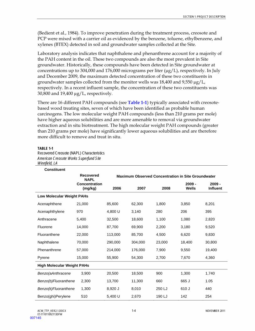
There are 16 different PAH compounds (see Table 1-1) typically associated with creosote-based wood treating sites, seven of which have been identified as probable human carcinogens. The low molecular weight PAH compounds (less than 210 grams per mole) have higher aqueous solubilities and are more amenable to removal via groundwater extraction and in situ biotreatment. The high molecular weight PAH compounds (greater than 210 grams per mole) have significantly lower aqueous solubilities and are therefore more difficult to remove and treat in situ.
TABLE 1-1 Recovered Creosote (NAPL) Characteristics American Creosote Works Superfund Site Winnfield, LA
Constituent Recovered
NAPL Concentration
(mg/kg)
Maximum Observed Concentration in Site Groundwater
2006 2007 2008 2009 - Wells
2009 - Influent
Low Molecular Weight PAHs
Acenaphthene 21,000 85,600 62,300 1,800 3,850 8,201
Acenaphthylene 970 4,800 U 3,140 280 206 395
Anthracene 5,400 32,500 18,600 1,100 1,080 2,820
Fluorene 14,000 87,700 69,900 2,200 3,180 9,520
Fluoranthene 22,000 113,000 85,700 4,500 6,620 9,830
Naphthalene 70,000 290,000 304,000 23,000 18,400 30,800
Phenanthrene 57,000 214,000 176,000 7,900 9,550 19,400
Pyrene 15,000 55,900 54,300 2,700 7,670 4,360
High Molecular Weight PAHs
Benzo(aAnthracene 3,900 20,500 18,500 900 1,300 1,740
Benzo(b)Fluoranthene 2,300 13,700 11,300 660 665 J 1.05
Benzo(k)Fluoranthene 1,300 8,920 J 8,010 250 LJ 610 J 440
Benzo(ghi)Perylene 510 5,400 U 2,670 190 LJ 142 254
007145

SECTION 1: PROJECT DESCRIPTION
ACW_TTP_VER2.1.DOCX 1-5 NOVEMBER 2011 ES111011092113DFW
TABLE 1-1 Recovered Creosote (NAPL) Characteristics American Creosote Works Superfund Site Winnfield, LA
Constituent Recovered
NAPL Concentration
(mg/kg)
Maximum Observed Concentration in Site Groundwater
2006 2007 2008 2009 - Wells
2009 - Influent
Benzo(a)Pyrene 420 11,800 9,880 430 LJ 575 J 748
Chrysene 3,800 19,500 15,400 760 1,440 1,470
Dibenzo(a,h)Anthracene
260 5,800 U 1,090 60 LJ 62 J 79.7
Indeno(123-cd)Pyrene 490 5,000 U 3,070 180 LJ 127 J 253
Others
Bis(2-ethylhexyl)Phthalate
100 Not Tracked
Not Tracked
Not Tracked
Not Tracked
100 U
Dibenzofuran 11,000 Not Tracked
Not Tracked
Not Tracked
Not Tracked
Not Tested
2-Methylnaphthalene
14,000 Not Tracked
Not Tracked
Not Tracked
Not Tracked
Not Tested
Pentachlorophenol 1,100 285 360 110 J 144 500 U
Benzene Not Measured 362 330 327 271 20 U
Notes: aRecovered oil testing performed in November 2007 revealed a specific gravity of 1.03.
Italicized compounds are identified as carcinogenic.
B = Indicates analyte found in associated method blank
J = estimated concentration
mg/kg = milligrams per kilogram
U = not detected
Receptors There are no complete current human exposure pathways within the fence-enclosed portion of the Site. A layer of clean fill material, varying in thickness between 1 and 3 feet, prevents direct contact with contaminated subsurface soil by onsite remedial action workers. A perimeter fence and locking gate restrict access to the Site by offsite residents. An electronic surveillance system monitors the Site entrance gate, building, and grounds when remedial action workers are not onsite. There is no indication that shallow aquifer groundwater is being used in the immediate vicinity of the Site. Drinking water for nearby residents is supplied by the City of Winnfield from deep water supply wells constructed in the Sparta aquifer. Sampling of the City’s water supply well during the 1992 RI showed no evidence of Site-related contaminants (CDM, 1992).
007146
SECTION 1: PROJECT DESCRIPTION
ACW_TTP_VER2.1.DOCX 1-6 NOVEMBER 2011 ES111011092113DFW
Ecological exposure pathways, specifically those associated with Creosote Branch Creek, have not been directly evaluated since completion of the 1992 RI/FS. As indicated in the ROD, the selected remedy is to perform ecological monitoring for an estimated 5- to 10-year period after completion of remedial activities. The recent risk assessment update, Risk Assessment American Creosote Works Superfund Site (CH2M HILL, 2011b), compared contaminant concentrations detected in surface water and sediment samples collected in February 2008 to ecological protection screening levels. Several site-related contaminants were present at concentrations greater than the screening levels deemed protective of benthic invertebrate species.
1.2.3 Long-term Treatment Goals The primary long-term goal is to protect human health and the environment by reducing PAH concentrations in soil and groundwater to levels that protect future site, groundwater, and surface water uses.
Remedial Goals in Current ROD According to the ROD, the remedial goals for soils are 3,000 micrograms per kilogram (µg/kg) for carcinogenic PAHs expressed as benzo(a)pyrene (BaP) equivalents and 50,000 µg/kg for PCP. For groundwater, the remedial goals are 0.2 µg/L for PAHs expressed as BaP equivalents and 5 µg/L for benzene (EPA, 1993). These remedial goals were developed to be protective of site soils assuming a residential land use scenario and groundwater as a future drinking water source.
The ROD did not specify a remedial goal for PCP in groundwater. A 1-µg/L concentration has been assumed for the purposes of evaluating overall remedy performance. The 1-µg/L concentration corresponds to the federal drinking water standard or maximum contaminant level.
Year 2009 groundwater monitoring results indicate that PAH concentrations below the remedial goal were present at 15 of 18 active monitor well locations that lie outside the NAPL source zone footprint (see Figure 1-4). Within the NAPL source zone footprint, PAH concentrations less than the remedial goal were present at one of seven active monitor well locations (CH2M HILL, 2010b). These data indicate that NAPL removal or stabilization would improve the ability to attain the Site remedial goals.
PCP was detected in 8 of the 26 samples taken in December 2009 at concentrations between 0.22 and 96.8 µg/L. Benzene concentrations observed in the December 2009 samples ranged from less than 0.5 to 271 µg/L. Benzene concentrations greater than the 5-µg/L ROD standard were detected at 7 of 26 shallow aquifer monitor well locations.
Preliminary Remedial Goals in ROD Amendment The risk assessment update (CH2M HILL, 2011b) reassessed current and future potential risks to human health assuming that the Site would be redeveloped in the future for industrial purposes. Restoration of groundwater quality to allow for future drinking water beneficial use was also presumed based on classification of the Site’s shallow and deep aquifers using State of Louisiana Risk Evaluation Corrective Action Plan (RECAP) regulations. Based on these proposed land and groundwater uses, preliminary remedial goals (PRG) were proposed in the Draft Feasibility Study – Remedial Action Technology
007147
SECTION 1: PROJECT DESCRIPTION
ACW_TTP_VER2.1.DOCX 1-7 NOVEMBER 2011 ES111011092113DFW
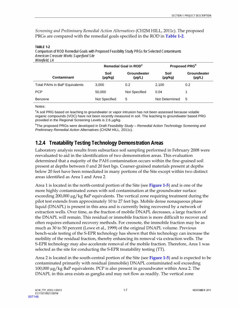
Screening and Preliminary Remedial Action Alternatives (CH2M HILL, 2011c). The proposed PRGs are compared with the remedial goals specified in the ROD in Table 1-2.
TABLE 1-2 Comparison of ROD Remedial Goals with Proposed Feasibility Study PRGs for Selected Contaminants American Creosote Works Superfund Site Winnfield, LA
Contaminant
Remedial Goal in RODa Proposed PRGb
Soil (µg/kg)
Groundwater (µg/L)
Soil (µg/kg)
Groundwater (µg/L)
Total PAHs in BaP Equivalents 3,000 0.2 2,100 0.2
PCP 50,000 Not Specified 0.04 1
Benzene Not Specified 5 Not Determined 5
Notes: aA soil PRG based on leaching to groundwater or vapor intrusion has not been assessed because volatile organic compounds (VOC) have not been recently measured in soil. The leaching to groundwater based PRG provided in the Regional Screening Levels is 2.6 µg/kg. bThe proposed PRGs were developed in Draft Feasibility Study – Remedial Action Technology Screening and Preliminary Remedial Action Alternatives (CH2M HILL, 2011c).
1.2.4 Treatability Testing Technology Demonstration Areas Laboratory analysis results from subsurface soil sampling performed in February 2008 were reevaluated to aid in the identification of two demonstration areas. This evaluation determined that a majority of the PAH contamination occurs within the fine-grained soil present at depths between 0 and 20 feet bgs. Coarser-grained materials present at depths below 20 feet have been remediated in many portions of the Site except within two distinct areas identified as Area 1 and Area 2.
Area 1 is located in the north-central portion of the Site (see Figure 1-5) and is one of the more highly contaminated zones with soil contamination at the groundwater surface exceeding 200,000 µg/kg BaP equivalents. The vertical zone requiring treatment during the pilot test extends from approximately 10 to 27 feet bgs. Mobile dense nonaqueous phase liquid (DNAPL) is present in this area and is currently being recovered by a network of extraction wells. Over time, as the fraction of mobile DNAPL decreases, a large fraction of the DNAPL will remain. This residual or immobile fraction is more difficult to recover and often requires enhanced recovery methods. For creosote, the immobile fraction may be as much as 30 to 50 percent (Lowe et al., 1999) of the original DNAPL volume. Previous bench-scale testing of the S-EPR technology has shown that this technology can increase the mobility of the residual fraction, thereby enhancing its removal via extraction wells. The S-EPR technology may also accelerate removal of the mobile fraction. Therefore, Area 1 was selected as the site for conducting the S-EPR treatability testing (TT).
Area 2 is located in the south-central portion of the Site (see Figure 1-5) and is expected to be contaminated primarily with residual (immobile) DNAPL contaminated soil exceeding 100,000 µg/kg BaP equivalents. PCP is also present in groundwater within Area 2. The DNAPL in this area exists as ganglia and may not flow as readily. The vertical zone
007148
SECTION 1: PROJECT DESCRIPTION
ACW_TTP_VER2.1.DOCX 1-8 NOVEMBER 2011 ES111011092113DFW
requiring treatment in this area extends from approximately 15 to 25 feet bgs. The TT in Area 2 will evaluate ISCO as a thermal enhancement technology to improve flow (recovery) of the residual DNAPL and a contaminant destruction technology to treat dissolved-phase contaminants.
The ISS TT will be conducted on the bench scale and will use material obtained from Area 2 as this is the area of the Site where the technology is most like to be employed, and the area where the highest concentration of PAH-contaminated media occurs.
007149
ACW_TTP_VER2.1.DOCX 2-1 NOVEMBER 2011 ES111011092113DFW
SECTION 2
Treatment Technology Description
As described in Draft Feasibility Study – Remedial Action Technology Screening and Preliminary Remedial Action Alternatives (CH2M HILL, 2011c), an array of preliminary remedial action alternatives have been developed to address: (1) vadose zone soil, (2) the NAPL source area, and (3) shallow aquifer groundwater. The remedial technologies employed by the vadose zone soil and shallow aquifer groundwater remedial action alternatives do not require additional site-specific information prior to their development and evaluation in the feasibility study. However, three of the NAPL source area remedial action alternatives rely on innovative technologies that require additional site-specific evaluation prior to development for feasibility study purposes. These three alternatives are: Enhanced NAPL Recovery (Alternative SG-3), Solidification/Stabilization (Alternative SG-4), and In Situ Thermal Destruction (Alternative SG-6).
This TTP will evaluate the technologies that would be employed under the Enhanced NAPL Recovery and Solidification/Stabilization remedial action alternatives. Consultations with the vendor that markets the In Situ Thermal Destruction technology have determined that field-scale pilot testing of this technology is not cost-effective at this time. Therefore, pilot test results from comparable sites and/or vendor recommendations will be used to develop the technical and cost information necessary for this remedial action alternative. This section presents a description of the enhanced NAPL recovery and solidification/stabilization technologies to be evaluated by the TTP.
The site-wide remedy for ACW selected in a ROD amendment will likely include a vadose zone component, an NAPL source area component, and a groundwater component. The information obtained from this TTP will not only determine how well the enhanced NAPL recovery and solidification/stabilization technologies will perform in the NAPL source area, but will also provide information that will help in selecting vadose zone and groundwater remedial action alternatives that are complementary.
2.1 In Situ Chemical Oxidation ISCO is an aggressive technology used for the rapid in situ treatment of a variety of organic contaminants in groundwater. ISCO is implemented through the subsurface injection of chemical oxidants, resulting in contaminants being oxidized to carbon dioxide (CO2) and other innocuous compounds. The most widely used oxidants include catalyzed hydrogen peroxide (CHP), permanganate as either sodium permanganate or potassium permanganate, sodium persulfate, and ozone.
ISCO is typically employed for the degradation of chlorinated ethenes, such as trichloroethene (Siegrist et al., 2001), and is most effective in source zone treatment. CHP has been demonstrated to effectively oxidize creosote-related compounds (Valderrama et. al., 2009; Lundstedt et. al., 2006). In addition, CHP has been used to elevate the subsurface temperature, resulting in enhanced PAH desorption and creosote mobility. Therefore, PAH concentrations in the dissolved phase are increased, where they are susceptible to
007150

SECTION 2: TREATMENT TECHNOLOGY DESCRIPTION
ACW_TTP_VER2.1.DOCX 2-2 NOVEMBER 2011 ES111011092113DFW
destruction via chemical oxidation, and the oil is more readily extracted. CHP can also directly oxidize DNAPL. Although ISCO may temporarily impact the microbial population in the injection area, microbial activity rebounds quickly as the aquifer returns to baseline conditions. Byproducts of the ISCO degradation of PAHs may include shorter-chained compounds, which are, generally, more easily degraded by biological processes than the parent compounds. For the purposes of this TT, the use of ISCO to thermally enhance DNAPL recovery will be evaluated.
The ISCO reagents are usually distributed in the aquifer using either permanently or temporarily installed injection wells or the drill rods of a direct-push technology rig. Though ISCO is generally used to address dissolved-phase contaminants, some vendors such as Geo-Cleanse International, Inc. (GCI), have employed CHP combined with extraction technology to treat NAPL contaminated media.
2.1.1 Key Uncertainties Key uncertainties for this technology include the following:
Ability to Inject Oxidant. ISCO effectiveness is highly dependent on the ability to distribute the oxidant throughout the subsurface because it must come into direct contact with the contaminants. Formations with low permeability may not allow sufficient distribution of chemical outwardly from the injection point (radius of influence [ROI]) or over an entire vertical interval because of heterogeneity. Also, low permeability formations may impact application costs by limiting chemical injection rates or requiring a more closely spaced array of injection points.
Ability to Make Contaminant-Oxidant Contact. In addition to the challenges associated with delivering the oxidant, the success of the treatment depends on being able to attain the proper concentrations of oxidant at the site of the contaminant.
NAPL Extraction. It is not known how much of the DNAPL mass can be removed using ISCO and extraction well recovery or what the final residual saturation content will be in the subsurface following the ISCO application and extraction. Furthermore, there is some uncertainty on how much DNAPL mass remains at the Site. So an estimate of DNAPL removed as a function of unit area treatment may not reliably estimate total treatment costs for DNAPL removal in the remaining portions of the Site.
Optimal Chemical Dose Rates and Frequency of Application. Aquifer geochemistry significantly impacts oxidant performance and determines whether catalyzing or sequestering agents will be required to optimize peroxide longevity in the subsurface. In addition, multiple ISCO applications will likely be necessary to achieve the desired results.
Impact to the PLTS. The PLTS effectiveness may be impacted in a positive and/or negative manner, such as improved or diminished efficiency resulting from chemical compatibility issues, degradation byproducts, slugs of NAPL coming into the system, and so forth.
007151
SECTION 2: TREATMENT TECHNOLOGY DESCRIPTION
ACW_TTP_VER2.1.DOCX 2-3 NOVEMBER 2011 ES111011092113DFW
2.2 S-EPR S-EPR entails the use of a proprietary solution, VeruSOL, to increase solubility of organic compounds, making them more mobile for recovery purposes. VeruSOL, which is biodegradable, is a combination of food-grade, citrus-based co-solvents and plant oil-based surfactants. VeruSOL has been shown to increase total concentrations of NAPL in solution between one and three orders of magnitude. In a bench test conducted by VeruTEK in 2008, using materials from the Site, the total concentration of volatile organic compounds (VOC) was increased by 5-fold, semivolatile organic compounds (SVOC) by 24-fold, and total petroleum hydrocarbons (TPH) by 65-fold (VeruTEK, 2008).
2.2.1 Key Uncertainties Key uncertainties for this technology include the following:
Ability to Inject Surfactant. The effectiveness of S-EPR is highly dependent on the distribution of chemicals (ROI) in the subsurface because the surfactant must come into direct contact with contaminants. Formations with low permeability may not allow sufficient distribution of fluids to attain reasonable ROI or over an entire vertical interval because of formation heterogeneity. Also, low permeability formations may impact application costs by limiting chemical injection rates.
DNAPL Extraction. It is not known how much of the DNAPL mass can be removed using S-EPR or what the final residual saturation content will be in the subsurface following the S-EPR application and extraction. Furthermore, there is some uncertainty on how much DNAPL mass remains at the Site. Therefore an estimate of DNAPL removed as a function of unit area treatment may not reliably estimate total treatment costs for DNAPL removal in the remaining portions of the Site.
Optimal Chemical Dose Rates. The amount of S-EPR required per application and the number of applications required to achieve the desired results have not been tested at the field scale. During the 2008 bench testing, an 86% reduction in TPH mass associated with creosote oil was achieved using a 10 g/L VeruSOL-10 solution followed by a 4% hydrogen peroxide solution. The treatability test will not include hydrogen peroxide treatment because field testing conducted at other sites since the bench test was completed indicate these same results can be achieved without the use of hydrogen peroxide (CH2M HILL, 2011d).
Impact to the PLTS. The PLTS effectiveness may be impacted in a positive and/or negative manner, such as improved or diminished efficiency resulting from chemical compatibility issues, degradation byproducts, slugs of NAPL coming into the system, and so forth.
2.3 In Situ Solidification/Stabilization ISS entails the injection and mixing of solidifying reagents with the soil to form a monolithic, low-permeability, solid mass with high structural integrity, which reduces the mobility and solubility of contaminants originally present in the soil. Prior to full-scale field application, competent design of an ISS application requires a bench-scale test to collect
007152
SECTION 2: TREATMENT TECHNOLOGY DESCRIPTION
ACW_TTP_VER2.1.DOCX 2-4 NOVEMBER 2011 ES111011092113DFW
design data, including stabilization reagent mix ratios, injection quantity required for stabilization, and volume increase of the stabilized material.
To complete treatment, the stabilization reagents are mixed with soil in situ and allowed to cure. The ISS reagents may include Portland cement, fly ash, blast furnace slag, and organic sorbents, such as granular activated carbon, Zeolite, and organophilic clay. The organic sorbents adsorb organic contaminants within their structure, which is encapsulated into a cementitious matrix created by cement-based agents (that is, Portland cements and blast furnace slag). This process results in a solidified stable mass with high structural strength and low leaching potential.
During the soil mixing, large-diameter (approximately 8 to 10 feet) augers with mixing paddles and grout ports are drilled into the ground as a grout is pumped through the shaft. The grout, containing solidifying reagents, acts as an aid to drilling and is mixed into the soil column, creating a treated soil mass. The auger mixes the soil and grout by vertically passing the soil column through the auger multiple times. Treated soil must fully cure, typically for 7 days, before being covered with clean soil.
2.3.1 Key Uncertainties Key uncertainties for this technology include the following:
Design Parameters. Optimal reagent mix ratios, the injection quantity, and increase in volume of mixed material are uncertain.
Resulting Leaching Potential. It is not known how much contamination will leach from the final stabilized monolith.
Permeability. It has not been demonstrated that the permeability goals can be achieved with the site-specific media.
007153
ACW_TTP_VER2.1.DOCX 3-1 NOVEMBER 2011 ES111011092113DFW
SECTION 3
Test Objectives
The objectives for the TT were developed using the Data Quality Objectives (DQO) process (EPA, 2006). The DQO process resulted in the test objective of determining if one or more of the technologies included in the TT (ISCO, S-EPR, and ISS) should be retained for further evaluation in the FS. The recommendation to retain the technologies will be based on determination of the following:
The percent reduction in residual DNAPL mass that can be attained using ISCO via CHP
The percent reduction in DNAPL mass that can be attained using S-EPR
The reduction in DNAPL mobility and leachability that can be attained through ISS of DNAPL-impacted media
The cost to complete full-scale implementation of each technology, as estimated by interpretation of pilot study results and the conceptual site model (Note: Considerable uncertainty is expected in this cost estimate, because it is technically very difficult to estimate the total volume of creosote in the subsurface.)
Overall effectiveness of the technology in reducing risks to human health and the environment
TT objectives associated with reducing the toxicity, mobility, and volume (TMV) of dissolved-phase contaminants were not specifically addressed for this TTP. Due to the timeframes that may be required for these reductions to become evident, they will be assessed through semiannual groundwater monitoring conducted under the long-term remedial action task order, and the information will be incorporated into the TT or FS Report.
The DQO process used for the TT is summarized in the following subsections.
3.1 Step 1 – State the Problem Project Objectives The objective of the TT is to evaluate performance of three technologies (ISCO, S-EPR, and ISS) to treat areas of residual (immobile) and/or mobile DNAPL present at the Site. By destroying (ISCO), removing (ISCO and S-EPR), or immobilizing (ISS) NAPL source material, the longevity of the dissolved plume is reduced by minimizing the contribution of contaminants from the DNAPL.
Project Assumptions If one or more of these technologies is selected for full-scale application, it will likely be coupled with one or additional technologies (that is, combined remedy) to address the current dissolved-phase PAH plume or areas with very low concentrations of residual DNAPL.
007154
SECTION 3: TEST OBJECTIVES
ACW_TTP_VER2.1.DOCX 3-2 NOVEMBER 2011 ES111011092113DFW
Project Issues CH2M HILL will provide the technical and labor resources required to implement the TT, conduct performance monitoring during the TT, and evaluate the TT results. Based on the data evaluation, CH2M HILL will make recommendations on which technologies should be retained for the FS.
DQO Planning Team Members and Key Decision Makers The planning team will include CH2M HILL, the Louisiana Department of Environmental Quality (LDEQ), and the EPA.
Contaminants of Concern Contaminants of concern (COC) include PAHs, PCP, and benzene with naphthalene selected as a primary PAH indicator contaminant. On average, naphthalene, which is highly mobile in the dissolved phase, accounts for 35 percent of the total PAH concentration in the groundwater sample data set (CH2M HILL, 2011e), and 20 percent of the total PAH concentration in the year 2008 subsurface soil investigation data set (CH2M HILL, 2008).
Dioxins and furans will not be evaluated specifically, because their fate in each of the three TT tests is expected to be comparable to the high molecular weight PAH constituents.
Current and Potential Future Land Use The initial baseline risk assessment assumed a residential land use. Restoration of the Site to allow for a future residential use may be impracticable (cost prohibitive). Therefore, the FS will evaluate restoration to allow for future industrial land use or recreational land use with residential land use retained as a baseline for comparison. Future land use options will be explored further with EPA, the City of Winnfield, and LDEQ.
Statement of the Problem Can one or more of these technologies effectively address residual and/or mobile DNAPL such that future concentrations of COCs in Site soil and groundwater can be reduced to allow for conditional reuse?
3.2 Step 2 – Identify the Goals of the Study Principal Study Questions
What percentage of reduction in DNAPL mass will ISCO achieve during the pilot-scale testing?
What percentage of reduction in DNAPL mass will S-EPR achieve during the pilot-scale testing?
How will ISS reduce contaminant leachability during the bench-scale testing?
What is the cost to complete full-scale implementation of the technology per treatment volume?
Alternative Actions
Evaluation of an alternative technology
Additional pilot-scale testing
007155
SECTION 3: TEST OBJECTIVES
ACW_TTP_VER2.1.DOCX 3-3 NOVEMBER 2011 ES111011092113DFW
Decision Statement If one or more of these technologies is able to perform as specified, they will be retained for consideration during the FS.
3.3 Step 3 – Identify Information Input Information Required to Address the Problem
Ability to Implement. Is it possible to inject sufficient amounts of oxidant or surfactant in the ground or attain adequate subsurface mixing?
Contaminant Reduction. What percentage of reduction in DNAPL TMV can be reasonably achieved through implementation of these technologies such that the longevity of the dissolved-phase plume is reduced or eliminated?
Cost Parameters. Were all design criteria determined to the extent required to budget for a full-scale application?
Source of Required Information Sources of the required information will include historical data, data collected during the pilot-scale and bench-scale tests, performance data collection events, and the current conceptual site model.
Action Levels for Contaminants of Concern The action levels for COCs in groundwater specified in the ROD (EPA, 1993) are 0.2 µg/L for PAHs expressed as BaP equivalents and 5 µg/L for benzene. A 1-µg/L action level for PCP corresponding to the federal maximum contaminant level (MCL) is assumed. For COCs in soil, the cleanup levels included 50,000 µg/kg for PCP; 3,000 µg/kg for PAHs expressed as BaP equivalents; and less than 10 µg/kg for 2,3,7,8-tetrachlorodibenxop-dioxin. As indicated previously, the TT will not specifically evaluate the performance of these technologies with respect to dioxin. The analytical methods are outlined in Section 4.
The updated draft risk assessment report (CH2M HILL, 2011b) and Draft Feasibility Study – Remedial Action Technology Screening and Preliminary Remedial Action Alternatives (CH2M HILL, 2011c) proposed a new set of PRGs based on an industrial land use and potable groundwater beneficial use. A comparison of the proposed PRGs versus the ROD remedial goals is provided in Table 1-2.
3.4 Step 4 – Define the Boundaries of the Study Target Population of Interest The target population consists of all validated soil and groundwater data collected from the test areas or during bench-scale testing.
Spatial Boundaries of the Test Areas The spatial boundary for the ISCO (Area 1) and S-EPR (Area 2) pilot-scale tests are shown on Figure 1-5. Soil samples for the ISS bench-scale test will be collected from within the S-EPR test area (Area 2).
007156

SECTION 3: TEST OBJECTIVES
ACW_TTP_VER2.1.DOCX 3-4 NOVEMBER 2011 ES111011092113DFW
Temporal Boundaries of the Test Areas The performance monitoring sampling parameters and frequency are summarized in Section 4.
Conditions Most Favorable for Collecting Data There are no specific weather or time conditions that are more favorable for collecting data. However, because the TT will be conducted within highly contaminated zones, sampling to evaluate the ability of the technology to treat contaminants should be completed quickly after completion of the injection/extraction processes, before contamination from adjacent, untreated areas migrates into the treatment cell. Because the ISS bench-scale test will be conducted in a laboratory setting, there are no special conditions for data collection.
Practical Constraints Affecting Data Collection Constraints include holding times for the analyses. The field sampling procedures, including equipment and monitor well purging requirements, will be outlined in Appendix B.
Scale of Decision Making For the field pilot-scale tests, soil and groundwater throughout the thickness of the shallow aquifer will be sampled. The data from the baseline sampling event will be compared to the performance monitoring data to determine if the test objectives/uncertainties were achieved. For the bench-scale test, solidified materials will be tested for strength, permeability, and leachability.
3.5 Step 5 – Develop the Analytic Approach Statistical Parameter of Interest for Decision Making The average and maximum contaminant concentrations in groundwater and soil within the test areas (Areas 1 and 2) of the Site will be used for decision making. Also, field data describing the ability to inject and extract ISCO and S-EPR materials will be evaluated. The ISS bench-scale test will take the average and highest contaminant concentrations in soil and monolith permeate, as well as strength and permeability, into consideration.
Decision Rules If the physical application of ISCO or S-EPR cannot be achieved, then these technologies will either not be retained in the FS or missing information required to improve or carry the technology forward will be provided.
If DNAPL in either test area is not reduced by a reasonable amount compared to the cost of implementation, then that technology will either not be retained for the FS or missing information required to improve or carry the technology forward will be provided.
If it is determined that the technology does not reduce risks to human health and the environment, then the technology will not be retained for the FS.
007157
SECTION 3: TEST OBJECTIVES
ACW_TTP_VER2.1.DOCX 3-5 NOVEMBER 2011 ES111011092113DFW
3.6 Step 6 – Specify Performance or Acceptance Criteria Acceptance of analytical data will be based on data validation conducted by CH2M HILL. All data will be considered useable unless specified during the data validation process. The results of the data validation will be provided in data validation reports.
3.7 Step 7 – Plan for Obtaining Data The sampling plan is summarized in Section 4.
007158

SECTION 3: TEST OBJECTIVES
ACW_TTP_VER2.1.DOCX 3-6 NOVEMBER 2011 ES111011092113DFW
(This page intentionally left blank)
007159
ACW_TTP_VER2.1.DOCX 4-1 NOVEMBER 2011 ES111011092113DFW
SECTION 4
Experimental Design and Procedures
The TT will be include the following phases of work:
Pre-test mobilization activities Baseline sampling Technology testing Performance and post-treatment sampling
All fieldwork will be conducted according to the HSP and HSP Addendum (see Appendix A).
4.1 Pre-test Mobilization Activities The pre-test mobilization activities will consist of coordination/scheduling with subcontractors (VeruTEK/Evergreen Resources Group, Inc. [ERGI], and GCI); review of subcontractor work plans, HSPs, and job hazard analyses; review of test area layouts, delivery of holding tanks, plumbing of extraction wellheads to the frac tanks, and construction of wellhead adapters for the injection wells.
Subcontractor Coordination. CH2M HILL will coordinate with the ISCO, S-EPR, ISS field, and laboratory subcontractors to finalize the test schedule. CH2M HILL will also review and approve subcontractor work plans and HSPs.
EPA Houston Laboratory Coordination. CH2M HILL has developed a list of pre- and post-testing analysis to be performed, the approximate dates the samples will be taken, and the required laboratory analytical methods and detection limits. This information will be compiled and submitted to the EPA Task Order Manager and EPA Laboratory Managers.
Site Setup. CH2M HILL will lay out the two field test areas, mark sample and well drilling locations using handheld global positioning system (GPS) equipment, and receive equipment, such as the frac tanks. One or two holding tanks will be delivered to each test area.
Utility Clearance. After the pilot-scale test areas have been layed out and the drilling locations have been flagged, onsite operations staff will perform utility clearance of the drilling locations for underground PLTS conveyance piping.
Plumbing. As needed, CH2M HILL will plumb the appropriate extraction wells to frac tanks for water recovery during the well rehabilitation and S-EPR and ISCO pilot-scale tests. Also, clean water for chemical mixing will be plumbed from either the PLTS or a City water supply to the two test areas.
007160
SECTION 4: EXPERIMENTAL DESIGN AND PROCEDURES
ACW_TTP_VER2.1.DOCX 4-2 NOVEMBER 2011 ES111011092113DFW
Because hazardous chemicals will be injected into the shallow aquifer during the field-scale TT, the Louisiana Office of Conservation – Underground Injection Control Section will be notified of the planned TT activities.
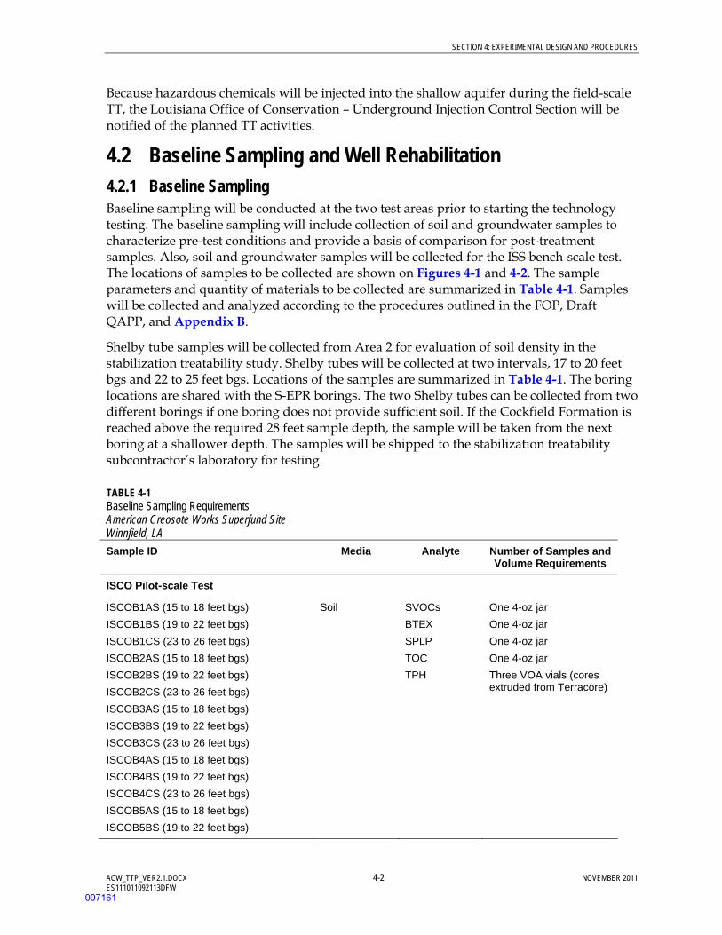
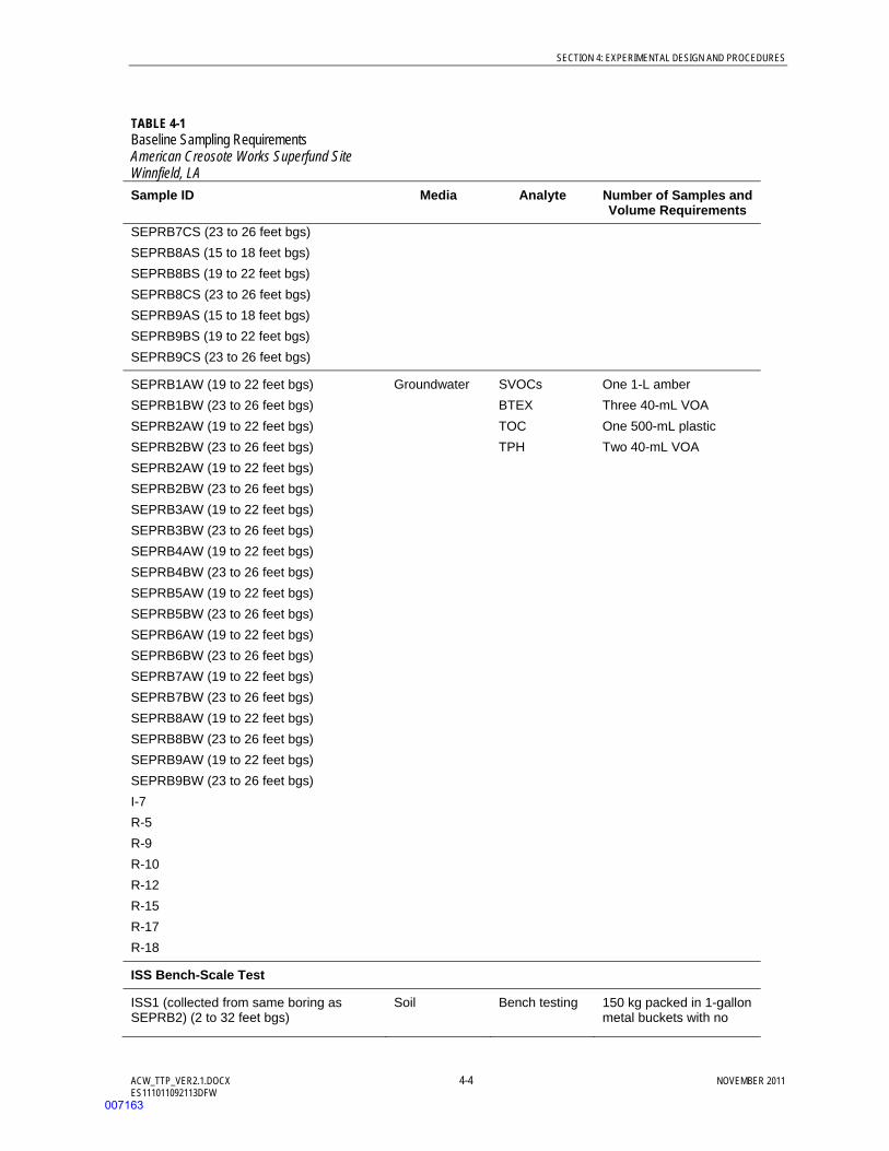
4.2 Baseline Sampling and Well Rehabilitation 4.2.1 Baseline Sampling Baseline sampling will be conducted at the two test areas prior to starting the technology testing. The baseline sampling will include collection of soil and groundwater samples to characterize pre-test conditions and provide a basis of comparison for post-treatment samples. Also, soil and groundwater samples will be collected for the ISS bench-scale test. The locations of samples to be collected are shown on Figures 4-1 and 4-2. The sample parameters and quantity of materials to be collected are summarized in Table 4-1. Samples will be collected and analyzed according to the procedures outlined in the FOP, Draft QAPP, and Appendix B.
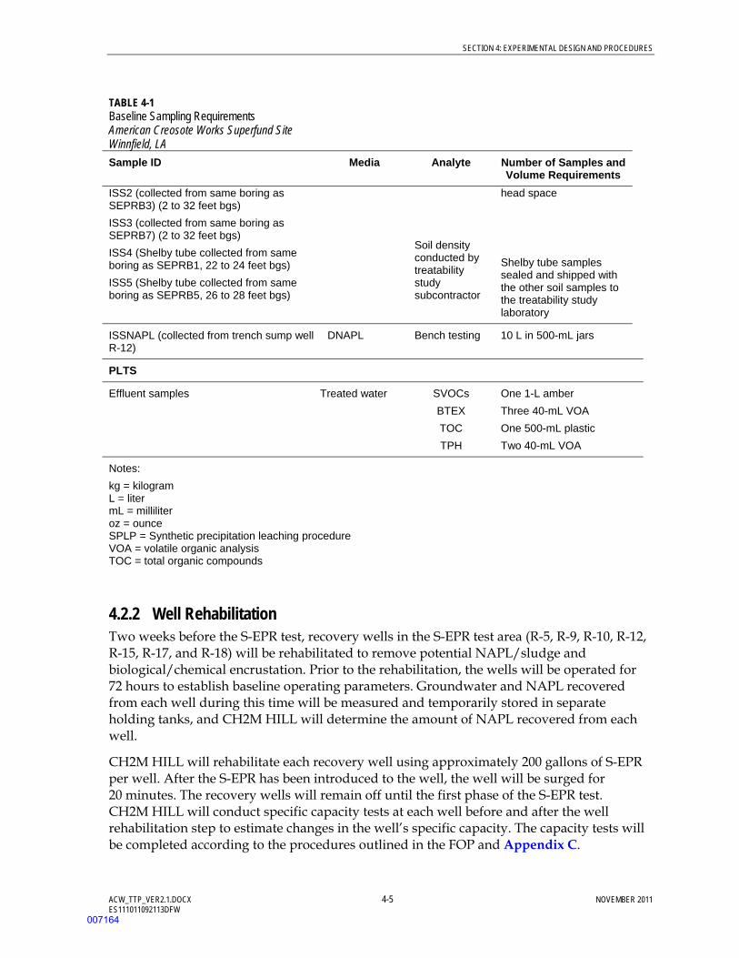
Shelby tube samples will be collected from Area 2 for evaluation of soil density in the stabilization treatability study. Shelby tubes will be collected at two intervals, 17 to 20 feet bgs and 22 to 25 feet bgs. Locations of the samples are summarized in Table 4-1. The boring locations are shared with the S-EPR borings. The two Shelby tubes can be collected from two different borings if one boring does not provide sufficient soil. If the Cockfield Formation is reached above the required 28 feet sample depth, the sample will be taken from the next boring at a shallower depth. The samples will be shipped to the stabilization treatability subcontractor’s laboratory for testing.
TABLE 4-1 Baseline Sampling Requirements American Creosote Works Superfund Site Winnfield, LA Sample ID Media Analyte Number of Samples and
Volume Requirements
ISCO Pilot-scale Test
ISCOB1AS (15 to 18 feet bgs)
ISCOB1BS (19 to 22 feet bgs)
ISCOB1CS (23 to 26 feet bgs)
ISCOB2AS (15 to 18 feet bgs)
ISCOB2BS (19 to 22 feet bgs)
ISCOB2CS (23 to 26 feet bgs)
ISCOB3AS (15 to 18 feet bgs)
ISCOB3BS (19 to 22 feet bgs)
ISCOB3CS (23 to 26 feet bgs)
ISCOB4AS (15 to 18 feet bgs)
ISCOB4BS (19 to 22 feet bgs)
ISCOB4CS (23 to 26 feet bgs)
ISCOB5AS (15 to 18 feet bgs)
ISCOB5BS (19 to 22 feet bgs)
Soil SVOCs
BTEX
SPLP
TOC
TPH
One 4-oz jar
One 4-oz jar
One 4-oz jar
One 4-oz jar
Three VOA vials (cores extruded from Terracore)
007161

SECTION 4: EXPERIMENTAL DESIGN AND PROCEDURES
ACW_TTP_VER2.1.DOCX 4-3 NOVEMBER 2011 ES111011092113DFW
TABLE 4-1 Baseline Sampling Requirements American Creosote Works Superfund Site Winnfield, LA Sample ID Media Analyte Number of Samples and
Volume Requirements ISCOB5CS (23 to 26 feet bgs)
ISCOB6AS (15 to 18 feet bgs)
ISCOB6BS (19 to 22 feet bgs)
ISCOB6CS (23 to 26 feet bgs)
ISCOB1AW (19 to 22 feet bgs)
ISCOB1BW (23 to 26 feet bgs)
ISCOB2AW (19 to 22 feet bgs)
ISCOB2BW (23 to 26 feet bgs)
ISCOB3AW (19 to 22 feet bgs)
ISCOB3BW (23 to 26 feet bgs)
ISCOB4AW (19 to 22 feet bgs)
ISCOB4BW (23 to 26 feet bgs)
ISCOB5AW (19 to 22 feet bgs)
ISCOB5BW (23 to 26 feet bgs)
ISCOB6AW (19 to 22 feet bgs)
ISCOB6BW (23 to 26 feet bgs)
I-5
Groundwater SVOCs
BTEX
TOC
TPH
One 1-L amber
Three 40-mL VOA
One 500-mL plastic
Two 40-mL VOA
S-EPR Pilot-Scale Test
SEPRB1AS (15 to 18 feet bgs)
SEPRB1BS (19 to 22 feet bgs)
SEPRB1CS (23 to 26 feet bgs)
SEPRB2AS (15 to 18 feet bgs)
SEPRB2BS (19 to 22 feet bgs)
SEPRB2CS (23 to 26 feet bgs)
SEPRB3AS (15 to 18 feet bgs)
SEPRB3BS (19 to 22 feet bgs)
SEPRB3CS (23 to 26 feet bgs)
SEPRB4AS (15 to 18 feet bgs)
SEPRB4BS (19 to 22 feet bgs)
SEPRB4CS (23 to 26 feet bgs)
SEPRB5AS (15 to 18 feet bgs)
SEPRB5BS (19 to 22 feet bgs)
SEPRB5CS (23 to 26 feet bgs)
SEPRB6AS (15 to 18 feet bgs)
SEPRB6BS (19 to 22 feet bgs)
SEPRB6CS (23 to 26 feet bgs)
SEPRB7AS (15 to 18 feet bgs)
SEPRB7BS (19 to 22 feet bgs)
Soil SVOCs
BTEX
SPLP
TOC
TPH
One 4-oz jar
One 4-oz jar
One 4-oz jar
One 4-oz jar
Three VOA vials (cores extruded from Terracore)
007162
SECTION 4: EXPERIMENTAL DESIGN AND PROCEDURES
ACW_TTP_VER2.1.DOCX 4-4 NOVEMBER 2011 ES111011092113DFW
TABLE 4-1 Baseline Sampling Requirements American Creosote Works Superfund Site Winnfield, LA Sample ID Media Analyte Number of Samples and
Volume Requirements SEPRB7CS (23 to 26 feet bgs)
SEPRB8AS (15 to 18 feet bgs)
SEPRB8BS (19 to 22 feet bgs)
SEPRB8CS (23 to 26 feet bgs)
SEPRB9AS (15 to 18 feet bgs)
SEPRB9BS (19 to 22 feet bgs)
SEPRB9CS (23 to 26 feet bgs)
SEPRB1AW (19 to 22 feet bgs)
SEPRB1BW (23 to 26 feet bgs)
SEPRB2AW (19 to 22 feet bgs)
SEPRB2BW (23 to 26 feet bgs)
SEPRB2AW (19 to 22 feet bgs)
SEPRB2BW (23 to 26 feet bgs)
SEPRB3AW (19 to 22 feet bgs)
SEPRB3BW (23 to 26 feet bgs)
SEPRB4AW (19 to 22 feet bgs)
SEPRB4BW (23 to 26 feet bgs)
SEPRB5AW (19 to 22 feet bgs)
SEPRB5BW (23 to 26 feet bgs)
SEPRB6AW (19 to 22 feet bgs)
SEPRB6BW (23 to 26 feet bgs)
SEPRB7AW (19 to 22 feet bgs)
SEPRB7BW (23 to 26 feet bgs)
SEPRB8AW (19 to 22 feet bgs)
SEPRB8BW (23 to 26 feet bgs)
SEPRB9AW (19 to 22 feet bgs)
SEPRB9BW (23 to 26 feet bgs)
I-7
R-5
R-9
R-10
R-12
R-15
R-17
R-18
Groundwater SVOCs
BTEX
TOC
TPH
One 1-L amber
Three 40-mL VOA
One 500-mL plastic
Two 40-mL VOA
ISS Bench-Scale Test
ISS1 (collected from same boring as SEPRB2) (2 to 32 feet bgs)
Soil Bench testing
150 kg packed in 1-gallon metal buckets with no
007163
SECTION 4: EXPERIMENTAL DESIGN AND PROCEDURES
ACW_TTP_VER2.1.DOCX 4-5 NOVEMBER 2011 ES111011092113DFW
TABLE 4-1 Baseline Sampling Requirements American Creosote Works Superfund Site Winnfield, LA Sample ID Media Analyte Number of Samples and
Volume Requirements ISS2 (collected from same boring as SEPRB3) (2 to 32 feet bgs)
ISS3 (collected from same boring as SEPRB7) (2 to 32 feet bgs)
ISS4 (Shelby tube collected from same boring as SEPRB1, 22 to 24 feet bgs)
ISS5 (Shelby tube collected from same boring as SEPRB5, 26 to 28 feet bgs)
Soil density conducted by treatability study subcontractor
head space
Shelby tube samples sealed and shipped with the other soil samples to the treatability study laboratory
ISSNAPL (collected from trench sump well R-12)
DNAPL Bench testing 10 L in 500-mL jars
PLTS
Effluent samples Treated water SVOCs
BTEX
TOC
TPH
One 1-L amber
Three 40-mL VOA
One 500-mL plastic
Two 40-mL VOA
Notes:
kg = kilogram L = liter mL = milliliter oz = ounce SPLP = Synthetic precipitation leaching procedure VOA = volatile organic analysis TOC = total organic compounds
4.2.2 Well Rehabilitation Two weeks before the S-EPR test, recovery wells in the S-EPR test area (R-5, R-9, R-10, R-12, R-15, R-17, and R-18) will be rehabilitated to remove potential NAPL/sludge and biological/chemical encrustation. Prior to the rehabilitation, the wells will be operated for 72 hours to establish baseline operating parameters. Groundwater and NAPL recovered from each well during this time will be measured and temporarily stored in separate holding tanks, and CH2M HILL will determine the amount of NAPL recovered from each well.
CH2M HILL will rehabilitate each recovery well using approximately 200 gallons of S-EPR per well. After the S-EPR has been introduced to the well, the well will be surged for 20 minutes. The recovery wells will remain off until the first phase of the S-EPR test. CH2M HILL will conduct specific capacity tests at each well before and after the well rehabilitation step to estimate changes in the well’s specific capacity. The capacity tests will be completed according to the procedures outlined in the FOP and Appendix C.
007164
SECTION 4: EXPERIMENTAL DESIGN AND PROCEDURES
ACW_TTP_VER2.1.DOCX 4-6 NOVEMBER 2011 ES111011092113DFW
If necessary, the temporary tank will be drained prior to starting the field tests by transferring the contents to the PLTS equalization tank.
Each of the four existing injection wells will also be rehabilitated by alternately swabbing and pumping the wells with the aid of a chemical dispersant. This step will help ensure that the recovery wells are functional for the ISCO and S-EPR testing.
4.3 Technology Testing 4.3.1 ISCO The ISCO pilot-scale test fieldwork will be conducted by GCI at Area 1 with oversight by CH2M HILL. Eight injection wells and four vent wells will be installed prior to the pilot test, as shown on Figure 4-1. The injection wells will be placed on 12-foot centers and screened across two injection intervals: 17 to 20 feet bgs and 22 to 25 feet bgs. The vent wells will be screened from the top of the confining layer (approximately 25 feet bgs) to 4 feet bgs. Drill cuttings will be containerized and characterized (if necessary) for offsite disposal. The drums will be labeled and stored according to the TDP (CH2M HILL, 2006c).
After installation, the injection and vent wells will be developed using standard well development methods. Following development, the vent wells will be pumped for 72 hours and all groundwater, and possibly NAPL, will be accumulated in the frac tank. CH2M HILL will evaluate the amount of NAPL collected during this time as a basis of comparison for the NAPL mobilized by the ISCO injection.
GCI will then inject approximately 15,300 pounds hydrogen peroxide over a 10-day period. The hydrogen peroxide will be shipped and staged as a 34 percent solution and will be mixed onsite to a maximum injection concentration of 11 percent. Process monitoring and data recording during the ISCO injection will be conducted by GCI. During this time, GCI will collect NAPL passively from the vent wells. If sufficient NAPL is present to warrant active NAPL recovery, GCI will coordinate use of a vacuum truck. The NAPL collected by GCI during pilot-scale testing will be measured to establish recovery volumes and transferred to the NAPL thickening tank at the PLTS.
Offgas (temperature and total VOC concentration) from the vent wells will be monitored for health and safety purposes using a photoionization detector, but will not be captured during the pilot testing. The frac tank contents will be monitored frequently to ensure there is sufficient capacity for recovered creosote/groundwater. The level of liquid in the frac tank will be kept to a minimum by transferring contents to the PLTS on a daily basis after measuring the creosote and water levels.
4.3.2 S-EPR The S-EPR pilot-scale test will be conducted by VeruTek and ERGI at Area 2 with oversight by CH2M HILL. Three injection wells will be installed prior to the pilot test, as shown on Figure 4-1. The injection wells will be screened from 17 to 27 feet bgs. Drill cuttings will be containerized and characterized (if necessary) for offsite disposal. The drums will be labeled and stored according to the TDP (CH2M HILL, 2006c).
007165
SECTION 4: EXPERIMENTAL DESIGN AND PROCEDURES
ACW_TTP_VER2.1.DOCX 4-7 NOVEMBER 2011 ES111011092113DFW
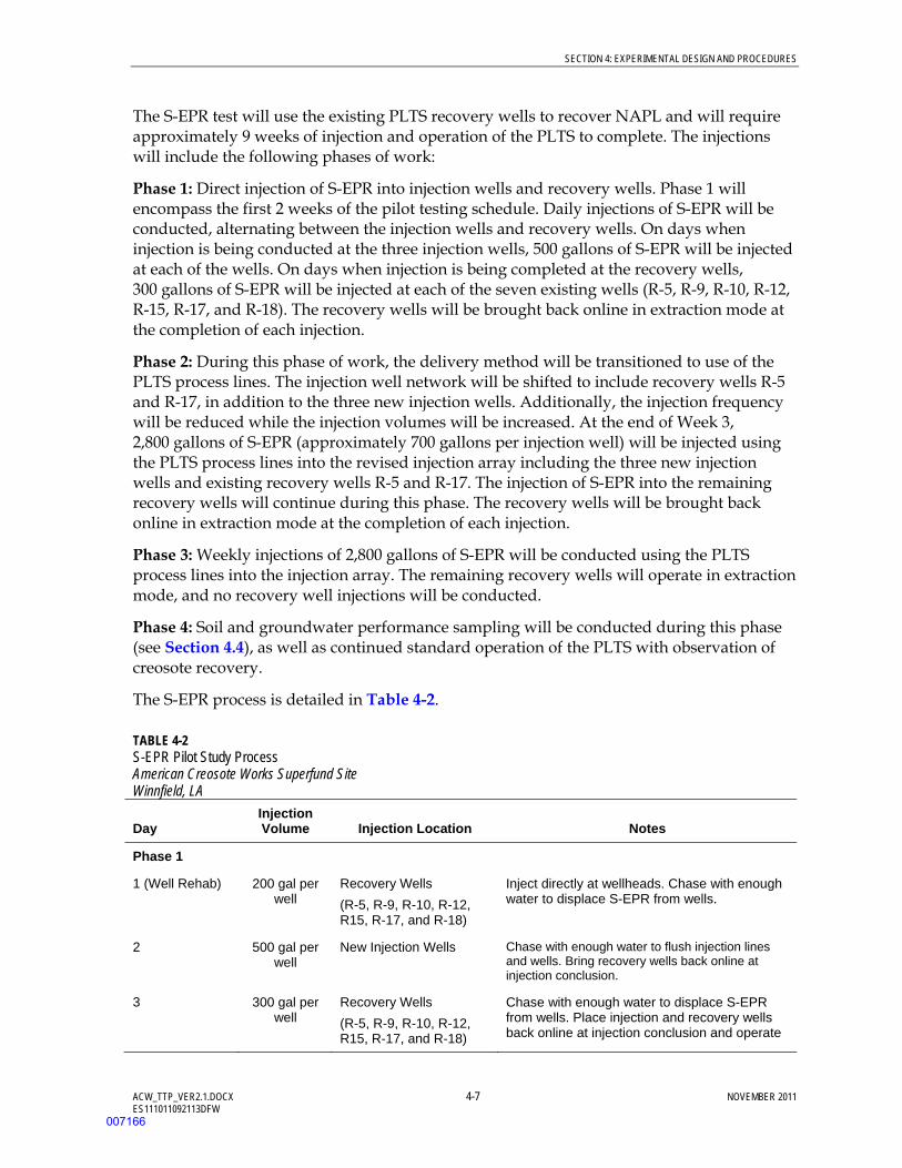
The S-EPR test will use the existing PLTS recovery wells to recover NAPL and will require approximately 9 weeks of injection and operation of the PLTS to complete. The injections will include the following phases of work:
Phase 1: Direct injection of S-EPR into injection wells and recovery wells. Phase 1 will encompass the first 2 weeks of the pilot testing schedule. Daily injections of S-EPR will be conducted, alternating between the injection wells and recovery wells. On days when injection is being conducted at the three injection wells, 500 gallons of S-EPR will be injected at each of the wells. On days when injection is being completed at the recovery wells, 300 gallons of S-EPR will be injected at each of the seven existing wells (R-5, R-9, R-10, R-12, R-15, R-17, and R-18). The recovery wells will be brought back online in extraction mode at the completion of each injection.
Phase 2: During this phase of work, the delivery method will be transitioned to use of the PLTS process lines. The injection well network will be shifted to include recovery wells R-5 and R-17, in addition to the three new injection wells. Additionally, the injection frequency will be reduced while the injection volumes will be increased. At the end of Week 3, 2,800 gallons of S-EPR (approximately 700 gallons per injection well) will be injected using the PLTS process lines into the revised injection array including the three new injection wells and existing recovery wells R-5 and R-17. The injection of S-EPR into the remaining recovery wells will continue during this phase. The recovery wells will be brought back online in extraction mode at the completion of each injection.
Phase 3: Weekly injections of 2,800 gallons of S-EPR will be conducted using the PLTS process lines into the injection array. The remaining recovery wells will operate in extraction mode, and no recovery well injections will be conducted.
Phase 4: Soil and groundwater performance sampling will be conducted during this phase (see Section 4.4), as well as continued standard operation of the PLTS with observation of creosote recovery.
The S-EPR process is detailed in Table 4-2.
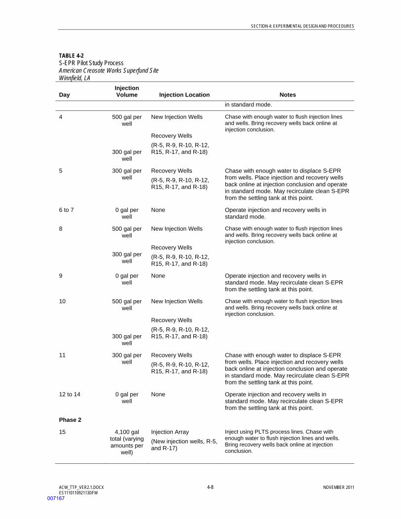
TABLE 4-2 S-EPR Pilot Study Process American Creosote Works Superfund Site Winnfield, LA
Day Injection Volume Injection Location Notes
Phase 1
1 (Well Rehab) 200 gal per well
Recovery Wells
(R-5, R-9, R-10, R-12, R15, R-17, and R-18)
Inject directly at wellheads. Chase with enough water to displace S-EPR from wells.
2 500 gal per well
New Injection Wells Chase with enough water to flush injection lines and wells. Bring recovery wells back online at injection conclusion.
3 300 gal per well
Recovery Wells
(R-5, R-9, R-10, R-12, R15, R-17, and R-18)
Chase with enough water to displace S-EPR from wells. Place injection and recovery wells back online at injection conclusion and operate
007166
SECTION 4: EXPERIMENTAL DESIGN AND PROCEDURES
ACW_TTP_VER2.1.DOCX 4-8 NOVEMBER 2011 ES111011092113DFW
TABLE 4-2 S-EPR Pilot Study Process American Creosote Works Superfund Site Winnfield, LA
Day Injection Volume Injection Location Notes
in standard mode.
4 500 gal per well
300 gal per well
New Injection Wells
Recovery Wells
(R-5, R-9, R-10, R-12, R15, R-17, and R-18)
Chase with enough water to flush injection lines and wells. Bring recovery wells back online at injection conclusion.
5 300 gal per well
Recovery Wells
(R-5, R-9, R-10, R-12, R15, R-17, and R-18)
Chase with enough water to displace S-EPR from wells. Place injection and recovery wells back online at injection conclusion and operate in standard mode. May recirculate clean S-EPR from the settling tank at this point.
6 to 7 0 gal per well
None Operate injection and recovery wells in standard mode.
8 500 gal per well
300 gal per well
New Injection Wells
Recovery Wells
(R-5, R-9, R-10, R-12, R15, R-17, and R-18)
Chase with enough water to flush injection lines and wells. Bring recovery wells back online at injection conclusion.
9 0 gal per well
None Operate injection and recovery wells in standard mode. May recirculate clean S-EPR from the settling tank at this point.
10 500 gal per well
300 gal per well
New Injection Wells
Recovery Wells
(R-5, R-9, R-10, R-12, R15, R-17, and R-18)
Chase with enough water to flush injection lines and wells. Bring recovery wells back online at injection conclusion.
11 300 gal per well
Recovery Wells
(R-5, R-9, R-10, R-12, R15, R-17, and R-18)
Chase with enough water to displace S-EPR from wells. Place injection and recovery wells back online at injection conclusion and operate in standard mode. May recirculate clean S-EPR from the settling tank at this point.
12 to 14 0 gal per well
None Operate injection and recovery wells in standard mode. May recirculate clean S-EPR from the settling tank at this point.
Phase 2
15 4,100 gal total (varying amounts per
well)
Injection Array
(New injection wells, R-5, and R-17)
Inject using PLTS process lines. Chase with enough water to flush injection lines and wells. Bring recovery wells back online at injection conclusion.
007167
SECTION 4: EXPERIMENTAL DESIGN AND PROCEDURES
ACW_TTP_VER2.1.DOCX 4-9 NOVEMBER 2011 ES111011092113DFW
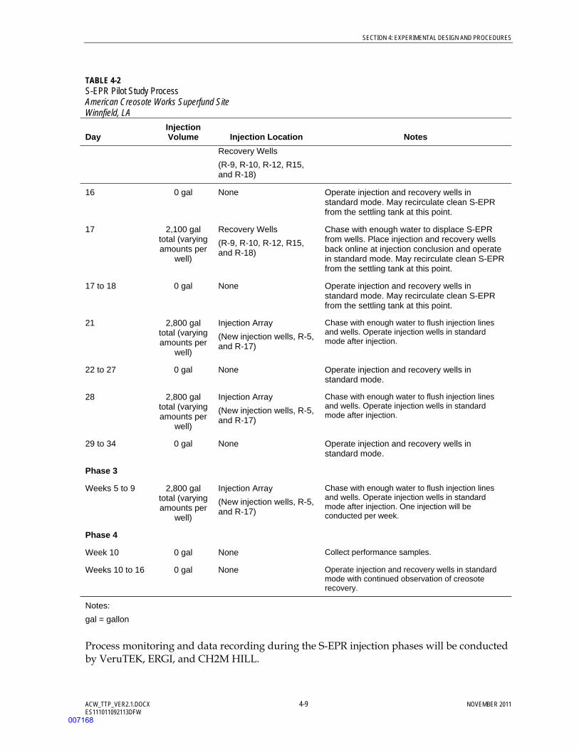
TABLE 4-2 S-EPR Pilot Study Process American Creosote Works Superfund Site Winnfield, LA
Day Injection Volume Injection Location Notes
Recovery Wells
(R-9, R-10, R-12, R15, and R-18)
16 0 gal None Operate injection and recovery wells in standard mode. May recirculate clean S-EPR from the settling tank at this point.
17 2,100 gal total (varying amounts per
well)
Recovery Wells
(R-9, R-10, R-12, R15, and R-18)
Chase with enough water to displace S-EPR from wells. Place injection and recovery wells back online at injection conclusion and operate in standard mode. May recirculate clean S-EPR from the settling tank at this point.
17 to 18 0 gal None Operate injection and recovery wells in standard mode. May recirculate clean S-EPR from the settling tank at this point.
21 2,800 gal total (varying amounts per
well)
Injection Array
(New injection wells, R-5, and R-17)
Chase with enough water to flush injection lines and wells. Operate injection wells in standard mode after injection.
22 to 27 0 gal None Operate injection and recovery wells in standard mode.
28 2,800 gal total (varying amounts per
well)
Injection Array
(New injection wells, R-5, and R-17)
Chase with enough water to flush injection lines and wells. Operate injection wells in standard mode after injection.
29 to 34 0 gal None Operate injection and recovery wells in standard mode.
Phase 3
Weeks 5 to 9 2,800 gal total (varying amounts per
well)
Injection Array
(New injection wells, R-5, and R-17)
Chase with enough water to flush injection lines and wells. Operate injection wells in standard mode after injection. One injection will be conducted per week.
Phase 4
Week 10 0 gal None Collect performance samples.
Weeks 10 to 16 0 gal None Operate injection and recovery wells in standard mode with continued observation of creosote recovery.
Notes:
gal = gallon
Process monitoring and data recording during the S-EPR injection phases will be conducted by VeruTEK, ERGI, and CH2M HILL.
007168
SECTION 4: EXPERIMENTAL DESIGN AND PROCEDURES
ACW_TTP_VER2.1.DOCX 4-10 NOVEMBER 2011 ES111011092113DFW
Contents of the holding tanks will be monitored frequently to ensure there is sufficient capacity for recovered creosote/groundwater. The level of liquid in the holding tanks will be kept to a minimum by transferring contents to the PLTS on a daily basis after measuring the creosote level.
4.3.3 Demobilization At the conclusion of both the ISCO and S-EPR pilot-scale tests, groundwater and NAPL stored in the frac tanks will be transferred to the PLTS in 2,000- to 5,000-gallon increments. Water/NAPL levels in the tanks will be checked hourly during the work day, and material will be transferred to the PLTS as needed to maintain a safe working volume. The site will be restored to pre-testing conditions prior to leaving the site. All personnel and equipment will be removed from the site at the conclusion of testing and site restoration.
4.3.4 ISS The ISS bench-scale test will be conducted by GeoSolutions, Inc., including the following activities:
Preparation and characterization of the untreated soil prior to the bench-scale test Evaluation of local availability and price of reagents Baseline mix development – development of physical strength by cement Mix development by addition of other reagents Final mix development – performance improvement in the long term
Preparation and Characterization of the Untreated Soil All soil samples, including the whole vertical zone from 2 to 35 feet bgs will be blended to create a composite for use during the bench-scale testing. This composite is expected to be representative of the vertical mixing that occurs during the soil mixing in the field. Thus, average moisture content of saturated and unsaturated soil will be representative of a single soil mixing column on the field. The blended soil will be sampled by the cone and quartering method, and the samples will be analyzed for the following:
Screen analysis to quantify the level of fines
Atterberg limits to measure the plasticity index and determine the composition of the clays
Total concentrations of moisture, PAHs (including naphthalene), benzene, PCP, and total organic carbon (TOC)
Synthetic precipitation leaching procedure (SPLP) for PAHs (including naphthalene), benzene, PCP, and TOC
Approximately one quarter of the composite soil sample will be blended with DNAPL to create a high-concentration sample that will measure the effectiveness of stabilization reagents if the auger intercepts a pool of DNAPL during the soil mixing. The high-concentration sample will be analyzed for the following:
Total concentrations of moisture, PAH (including naphthalene), BTEX, PCP, and TOC SPLP concentrations of PAH (including naphthalene), BTEX, PCP, and TOC
007169

SECTION 4: EXPERIMENTAL DESIGN AND PROCEDURES
ACW_TTP_VER2.1.DOCX 4-11 NOVEMBER 2011 ES111011092113DFW
Evaluation of Local Availability and Price of Reagents The key issues in reagent selection include the following:
Local availability Chemical characteristics Strength and permeability development results Consistency of supply Cost
An optimum reagent mix will be able to develop the required strength in the treated soil of 50 pounds per square inch (psi) (EPA, 1997) both in the vadose zone and aquifer, reduce permeability to minimize groundwater flux through the stabilized matrix, and reduce contaminant mobility in groundwater in a cost-effective way. Typical reagents that provide these features include the following:
Portland cement (to develop short-term strength)
Bentonite (required as a drilling lubricant for in situ applications)
Blast furnace slag (to increase long-term strength and reduce permeability)*
Type C fly ash (may reduce cement requirements when added to cement and increase long-term strength at reduced cost)*
Zeolite (may provide organic adsorption to reduce contaminant leachability and contribute to overall strength development)
Granular activated carbon (to reduce organic leachability)
Organophilic clay (to replace bentonite as a lubricant and absorb organic contaminants and reduce leachability)
*These amendments represent amendments with low carbon footprints.
This step of the bench-scale test will identify four stabilization reagents, in addition to Portland cement, to carry forward for additional bench-scale testing.
Baseline Mix Development – Development of Physical Strength by Cement The purpose of this step is to determine the injectability of the grout mix by measuring water addition requirements and viscosity, and to measure the physical and chemical characteristics of the stabilized soil after curing. Performance goals for ISS projects usually are based on SPLP (chemical characterization) and physical tests including hydraulic conductivity and unconfined compressive strength (UCS). Typically, the physical performance goals are a UCS of 50 psi and a permeability of less than 10-6 centimeters per second (cm/sec) (EPA, 1997), and these values will be used for this TT. Portland cement is used in this step to determine the level of cementitious reagent that needs to be added to achieve the performance goals.
The Portland cement mixes with various cement levels will be developed in 1 day and cast in 2-inch-diameter brass tubes. Six cylinders will be prepared for each mix, giving a total of 30 cylinders for a total of 5 mixes. Five cylinders from each group will be cured at ambient
007170
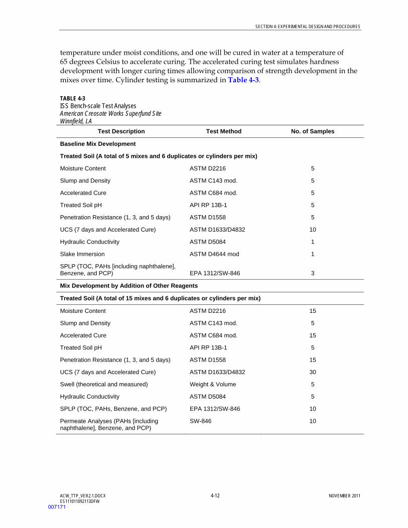
SECTION 4: EXPERIMENTAL DESIGN AND PROCEDURES
ACW_TTP_VER2.1.DOCX 4-12 NOVEMBER 2011 ES111011092113DFW
temperature under moist conditions, and one will be cured in water at a temperature of 65 degrees Celsius to accelerate curing. The accelerated curing test simulates hardness development with longer curing times allowing comparison of strength development in the mixes over time. Cylinder testing is summarized in Table 4-3.
TABLE 4-3 ISS Bench-scale Test Analyses American Creosote Works Superfund Site Winnfield, LA
Test Description Test Method No. of Samples
Baseline Mix Development
Treated Soil (A total of 5 mixes and 6 duplicates or cylinders per mix)
Moisture Content ASTM D2216 5
Slump and Density ASTM C143 mod. 5
Accelerated Cure ASTM C684 mod. 5
Treated Soil pH API RP 13B-1 5
Penetration Resistance (1, 3, and 5 days) ASTM D1558 5
UCS (7 days and Accelerated Cure) ASTM D1633/D4832 10
Hydraulic Conductivity ASTM D5084 1
Slake Immersion ASTM D4644 mod 1
SPLP (TOC, PAHs [including naphthalene], Benzene, and PCP) EPA 1312/SW-846 3
Mix Development by Addition of Other Reagents
Treated Soil (A total of 15 mixes and 6 duplicates or cylinders per mix)
Moisture Content ASTM D2216 15
Slump and Density ASTM C143 mod. 5
Accelerated Cure ASTM C684 mod. 15
Treated Soil pH API RP 13B-1 5
Penetration Resistance (1, 3, and 5 days) ASTM D1558 15
UCS (7 days and Accelerated Cure) ASTM D1633/D4832 30
Swell (theoretical and measured) Weight & Volume 5
Hydraulic Conductivity ASTM D5084 5
SPLP (TOC, PAHs, Benzene, and PCP) EPA 1312/SW-846 10
Permeate Analyses (PAHs [including naphthalene], Benzene, and PCP)
SW-846 10
007171
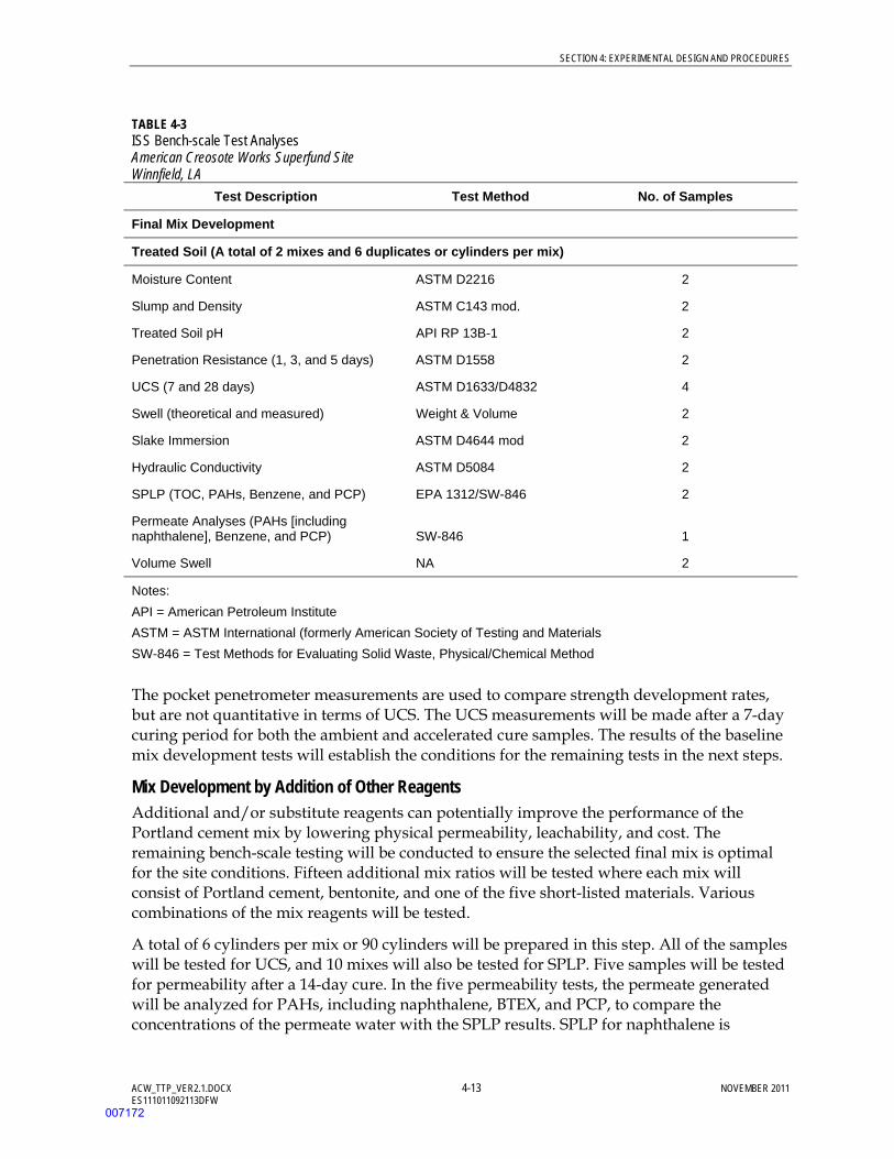
SECTION 4: EXPERIMENTAL DESIGN AND PROCEDURES
ACW_TTP_VER2.1.DOCX 4-13 NOVEMBER 2011 ES111011092113DFW
TABLE 4-3 ISS Bench-scale Test Analyses American Creosote Works Superfund Site Winnfield, LA
Test Description Test Method No. of Samples
Final Mix Development
Treated Soil (A total of 2 mixes and 6 duplicates or cylinders per mix)
Moisture Content ASTM D2216 2
Slump and Density ASTM C143 mod. 2
Treated Soil pH API RP 13B-1 2
Penetration Resistance (1, 3, and 5 days) ASTM D1558 2
UCS (7 and 28 days) ASTM D1633/D4832 4
Swell (theoretical and measured) Weight & Volume 2
Slake Immersion ASTM D4644 mod 2
Hydraulic Conductivity ASTM D5084 2
SPLP (TOC, PAHs, Benzene, and PCP) EPA 1312/SW-846 2
Permeate Analyses (PAHs [including naphthalene], Benzene, and PCP) SW-846 1
Volume Swell NA 2
Notes:
API = American Petroleum Institute
ASTM = ASTM International (formerly American Society of Testing and Materials
SW-846 = Test Methods for Evaluating Solid Waste, Physical/Chemical Method
The pocket penetrometer measurements are used to compare strength development rates, but are not quantitative in terms of UCS. The UCS measurements will be made after a 7-day curing period for both the ambient and accelerated cure samples. The results of the baseline mix development tests will establish the conditions for the remaining tests in the next steps.
Mix Development by Addition of Other Reagents Additional and/or substitute reagents can potentially improve the performance of the Portland cement mix by lowering physical permeability, leachability, and cost. The remaining bench-scale testing will be conducted to ensure the selected final mix is optimal for the site conditions. Fifteen additional mix ratios will be tested where each mix will consist of Portland cement, bentonite, and one of the five short-listed materials. Various combinations of the mix reagents will be tested.
A total of 6 cylinders per mix or 90 cylinders will be prepared in this step. All of the samples will be tested for UCS, and 10 mixes will also be tested for SPLP. Five samples will be tested for permeability after a 14-day cure. In the five permeability tests, the permeate generated will be analyzed for PAHs, including naphthalene, BTEX, and PCP, to compare the concentrations of the permeate water with the SPLP results. SPLP for naphthalene is
007172
SECTION 4: EXPERIMENTAL DESIGN AND PROCEDURES
ACW_TTP_VER2.1.DOCX 4-14 NOVEMBER 2011 ES111011092113DFW
normally higher than the results from the permeate water samples, because SPLP involves crushing the samples prior to the leaching procedure, while permeate sample is collected from the monolith of the treated soil. Finally, a long-term test will be conducted by immersing one or two stabilized samples in groundwater to demonstrate that the stabilized monolith maintains its physical integrity with time. This test will last approximately 84 days.
Analyses will be conducted on the grout and treated soil as detailed in Table 4-3. In addition, permeate from approximately five mixes will be collected during the permeability tests and analyzed for PAHs, including naphthalene, benzene, and PCP. Results of all of the analyses will provide data to determine which formula is most efficient at reducing permeability and organic compound leaching. Two formulas will be selected to proceed for final tests of refinements in the next step.
Final Mix Development – Performance Improvement in the Long Term The purpose of this step is to gather volume, strength, permeability, and leachability data on two final mixes with longer curing times (14 and 28 days), to demonstrate duplication of the results of previous tests and quantify improvements in these parameters over time. A final mix will be selected and recommended for the in situ soil mixing and stabilization. A cost comparison will also be conducted during this step to evaluate the cost effectiveness of the mixes.
A total of 12 cylinders will be prepared for the 2 mixes with 6 cylinders per mix. Analyses will be conducted as summarized in Table 4-3. In addition, the volume increase of the stabilized soils will be evaluated by mixing the soil and reagents and placing the mix in volume-specific containers. The volume of the cured material will be compared to the original soil volume.
4.4 Field Test Performance Sampling Performance sampling will be conducted at the two test areas as outlined in Sections 4.4.1 and 4.4.2. Performance sampling at Test Area 2 will be conducted after 10 weeks of injection while groundwater at Test Area 1 will be monitored periodically for presence of peroxide using field test kits. When oxidant is no longer present, the performance monitoring will be conducted. Performance sampling at both sites will include collection of soil and groundwater samples to characterize post-test conditions and provide data for comparison to pre-treatment samples. The locations of samples to be collected are shown on Figures 4-1 and 4-2. The sample parameters and quantity of materials to be collected are summarized in Table 4-4. Samples will be collected and analyzed according to the procedures outlined in the QAPP and Appendix B.
007173

SECTION 4: EXPERIMENTAL DESIGN AND PROCEDURES
ACW_TTP_VER2.1.DOCX 4-15 NOVEMBER 2011 ES111011092113DFW
TABLE 4-4 Performance Sampling Requirements American Creosote Works Superfund Site Winnfield, LA Sample ID Media Analyte Sample Number and
Volume Requirements
ISCO Pilot-scale Test
ISCOP1AS (15 to 18 feet bgs)
ISCOP1BS (19 to 22 feet bgs)
ISCOP1CS (23 to 26 feet bgs)
ISCOP2AS (15 to 18 feet bgs)
ISCOP2BS (19 to 22 feet bgs)
ISCOP2CS (23 to 26 feet bgs)
ISCOP3AS (15 to 18 feet bgs)
ISCOP3BS (19 to 22 feet bgs)
ISCOP3CS (23 to 26 feet bgs)
ISCOP4AS (15 to 18 feet bgs)
ISCOP4BS (19 to 22 feet bgs)
ISCOP4CS (23 to 26 feet bgs)
ISCOP5AS (15 to 18 feet bgs)
ISCOP5BS (19 to 22 feet bgs)
ISCOP5CS (23 to 26 feet bgs)
ISCOP6AS (15 to 18 feet bgs)
ISCOP6BS (19 to 22 feet bgs)
ISCOP6CS (23 to 26 feet bgs)
Soil SVOCs
BTEX
SPLP
TOC
TPH
One 4-oz jar
One 4-oz jar
One 4-oz jar
One 4-oz jar
Three VOA vials (cores extruded from
Terracore)
ISCOP1AW (19 to 22 feet bgs)
ISCOP1BW (23 to 26 feet bgs)
ISCOP2AW (19 to 22 feet bgs)
ISCOP2BW (23 to 26 feet bgs)
ISCOP3AW (19 to 22 feet bgs)
ISCOP3BW (23 to 26 feet bgs)
ISCOP4AW (19 to 22 feet bgs)
ISCOP4BW (23 to 26 feet bgs)
ISCOP5AW (19 to 22 feet bgs)
ISCOP5BW (23 to 26 feet bgs)
ISCOP6AW (19 to 22 feet bgs)
ISCOP6BW (23 to 26 feet bgs)
I-5
Groundwater SVOCs
BTEX
TOC
TPH
One 1-L amber
Three 40-mL VOA
One 500-mL plastic
Two 40-mL VOA
S-EPR Pilot-Scale Test
SEPRP1AS (15 to 18 feet bgs)
SEPRP1BS (19 to 22 feet bgs)
SEPRP1CS (23 to 26 feet bgs)
SEPRP2AS (15 to 18 feet bgs)
SEPRP2BS (19 to 22 feet bgs)
SEPRP2CS (23 to 26 feet bgs)
Soil SVOCs
BTEX
SPLP
TOC
TPH
One 4-oz jar
One 4-oz jar
One 4-oz jar
One 4-oz jar
Three VOA vials (cores extruded from
007174
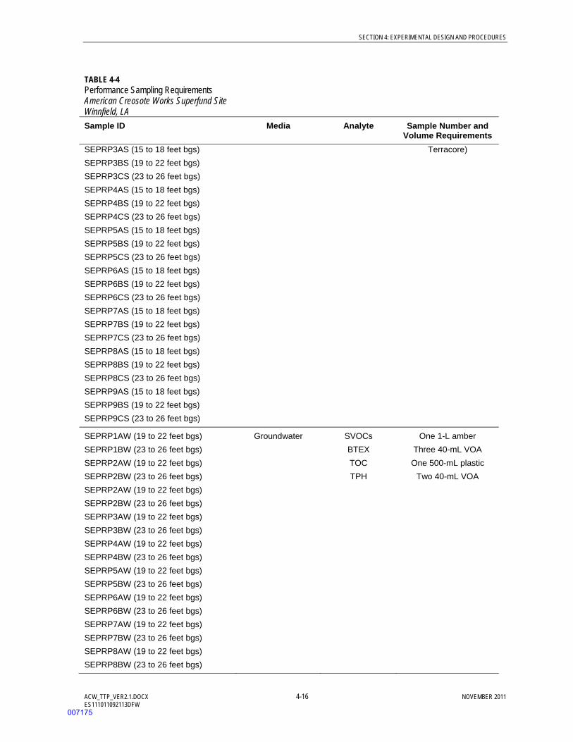
SECTION 4: EXPERIMENTAL DESIGN AND PROCEDURES
ACW_TTP_VER2.1.DOCX 4-16 NOVEMBER 2011 ES111011092113DFW
TABLE 4-4 Performance Sampling Requirements American Creosote Works Superfund Site Winnfield, LA Sample ID Media Analyte Sample Number and
Volume Requirements SEPRP3AS (15 to 18 feet bgs)
SEPRP3BS (19 to 22 feet bgs)
SEPRP3CS (23 to 26 feet bgs)
SEPRP4AS (15 to 18 feet bgs)
SEPRP4BS (19 to 22 feet bgs)
SEPRP4CS (23 to 26 feet bgs)
SEPRP5AS (15 to 18 feet bgs)
SEPRP5BS (19 to 22 feet bgs)
SEPRP5CS (23 to 26 feet bgs)
SEPRP6AS (15 to 18 feet bgs)
SEPRP6BS (19 to 22 feet bgs)
SEPRP6CS (23 to 26 feet bgs)
SEPRP7AS (15 to 18 feet bgs)
SEPRP7BS (19 to 22 feet bgs)
SEPRP7CS (23 to 26 feet bgs)
SEPRP8AS (15 to 18 feet bgs)
SEPRP8BS (19 to 22 feet bgs)
SEPRP8CS (23 to 26 feet bgs)
SEPRP9AS (15 to 18 feet bgs)
SEPRP9BS (19 to 22 feet bgs)
SEPRP9CS (23 to 26 feet bgs)
Terracore)
SEPRP1AW (19 to 22 feet bgs)
SEPRP1BW (23 to 26 feet bgs)
SEPRP2AW (19 to 22 feet bgs)
SEPRP2BW (23 to 26 feet bgs)
SEPRP2AW (19 to 22 feet bgs)
SEPRP2BW (23 to 26 feet bgs)
SEPRP3AW (19 to 22 feet bgs)
SEPRP3BW (23 to 26 feet bgs)
SEPRP4AW (19 to 22 feet bgs)
SEPRP4BW (23 to 26 feet bgs)
SEPRP5AW (19 to 22 feet bgs)
SEPRP5BW (23 to 26 feet bgs)
SEPRP6AW (19 to 22 feet bgs)
SEPRP6BW (23 to 26 feet bgs)
SEPRP7AW (19 to 22 feet bgs)
SEPRP7BW (23 to 26 feet bgs)
SEPRP8AW (19 to 22 feet bgs)
SEPRP8BW (23 to 26 feet bgs)
Groundwater SVOCs
BTEX
TOC
TPH
One 1-L amber
Three 40-mL VOA
One 500-mL plastic
Two 40-mL VOA
007175
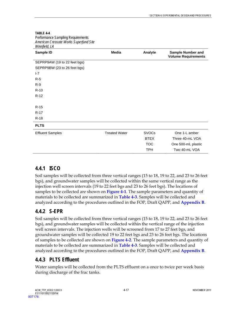
SECTION 4: EXPERIMENTAL DESIGN AND PROCEDURES
ACW_TTP_VER2.1.DOCX 4-17 NOVEMBER 2011 ES111011092113DFW
TABLE 4-4 Performance Sampling Requirements American Creosote Works Superfund Site Winnfield, LA Sample ID Media Analyte Sample Number and
Volume Requirements SEPRP9AW (19 to 22 feet bgs)
SEPRP9BW (23 to 26 feet bgs)
I-7
R-5
R-9
R-10
R-12
R-15
R-17
R-18
PLTS
Effluent Samples Treated Water SVOCs
BTEX
TOC
TPH
One 1-L amber
Three 40-mL VOA
One 500-mL plastic
Two 40-mL VOA
4.4.1 ISCO Soil samples will be collected from three vertical ranges (15 to 18, 19 to 22, and 23 to 26 feet bgs), and groundwater samples will be collected within the same vertical range as the injection well screen intervals (19 to 22 feet bgs and 23 to 26 feet bgs). The locations of samples to be collected are shown on Figure 4-1. The sample parameters and quantity of materials to be collected are summarized in Table 4-3. Samples will be collected and analyzed according to the procedures outlined in the FOP, Draft QAPP, and Appendix B.
4.4.2 S-EPR Soil samples will be collected from three vertical ranges (15 to 18, 19 to 22, and 23 to 26 feet bgs), and groundwater samples will be collected within the vertical range of the injection well screen intervals. The injection wells will be screened from 17 to 27 feet bgs, and groundwater samples will be collected 19 to 22 feet bgs and 23 to 26 feet bgs. The locations of samples to be collected are shown on Figure 4-2. The sample parameters and quantity of materials to be collected are summarized in Table 4-3. Samples will be collected and analyzed according to the procedures outlined in the FOP, Draft QAPP, and Appendix B.
4.4.3 PLTS Effluent Water samples will be collected from the PLTS effluent on a once to twice per week basis during discharge of the frac tanks.
007176

SECTION 4: EXPERIMENTAL DESIGN AND PROCEDURES
ACW_TTP_VER2.1.DOCX 4-18 NOVEMBER 2011 ES111011092113DFW
(This page intentionally left blank)
007177
ACW_TTP_VER2.1.DOCX 5-1 NOVEMBER 2011 ES111011092113DFW
SECTION 5
Data Analysis and Interpretation
5.1 ISCO and S-EPR Pilot-Scale Tests Process and performance monitoring data will be used to evaluate the following parameters:
Ability to distribute chemicals and ROI. Process data, such as flow rate and pressure, collected during the injection phases will be used to determine if it is possible to get adequate physical distribution of either oxidants or surfactants in the formation using either existing injection wells or new injection wells, and what the ROI around each injection point is. If it is not possible to inject chemicals efficiently, the injection well spacing may be reduced or alternative methods identified to allow for technology development and evaluation in the FS.
DNAPL recovery. The data will be used to determine the ability of the ISCO and S-EPR processes to enhance DNAPL recovery at the Site. If little or no increase in the DNAPL mass recovery rate is observed, the technology may not be retained for further consideration in the FS.
DNAPL removal. Visual soil logging and laboratory analysis data will be used to determine if the mass/volume of mobile and/or residual DNAPL has been reduced in the aquifer. If there is little or no change in the DNAPL mass/volume present within the treatment area, the technology may not be retained for further consideration in the FS.
Dissolved-phase treatment. The data will be used to determine if either the ISCO or S-EPR processes are able to reduce dissolved-phase contaminant concentrations. If a change in the dissolved-phase contaminant concentrations is not immediately observed, or detected through routine groundwater monitoring conducted under the LTRA task order, the technology may not be retained for further consideration in the FS.
Impact to the PLTS. If adverse conditions develop in the PLTS as a result of the application, the PLTS treatment modifications will be identified.
5.2 ISS Bench-scale Test The ISS test program is a procedure of screening and improving of reagent mixes as tests proceed. Thus, the data from one step will be used to evaluate the performance and refine reagent mixes for the next step. By the end of the test program, a final mix that meets the following performance goals will be generated:
UCS. If the final mix is not able to attain a UCS greater than 50 psi after curing, the technology may not be retained for further consideration in the FS.
Permeability. If a monolith permeability less than 10-6 cm/sec cannot be attained after curing, the technology may not be retained for further consideration in the FS.
007178

SECTION 5: DATA ANALYSIS AND INTERPRETATION
ACW_TTP_VER2.1.DOCX 5-2 NOVEMBER 2011 ES111011092113DFW
The treated soil that meets the above performance goals will reduce the NAPL mobility and contribution to the dissolved-phase concentrations. Permeate concentrations of the contaminants will be used to evaluate the leachability of the treated soil, which may be used in the consideration of other technology being coupled with the stabilization to reach overall project goals.
007179

ACW_TTP_VER2.1.DOCX 6-1 NOVEMBER 2011 ES111011092113DFW
SECTION 6
Reports
A report describing the TT processes and results will be issued at the conclusion of the testing. The Project Manager will update the Task Order Manager on testing progress through monthly status reports.
A draft report outline is provided below:
1 Introduction
1.1 Overview of Work Performed
1.1.1 ISCO Pilot Test
1.1.2 S-EPR Pilot Test
1.1.3 ISS Bench Test
1.2 Summary of Findings
2 ISCO Pilot Test
2.1 Field Activities
2.2 Results
3 S-EPR Pilot Test
3.1 Field Activities
3.2 Results
4 ISS Bench Test
4.1 Test Methods
4.2 Results
5 Recommendations
6 Works Cited
Tables
Figures
007180

SECTION 6: REPORTS
ACW_TTP_VER2.1.DOCX 6-2 NOVEMBER 2011 ES111011092113DFW
(This page intentionally left blank)
007181

ACW_TTP_VER2.1.DOCX 7-1 NOVEMBER 2011 ES111011092113DFW
SECTION 7
Schedule
The overall project schedule is provided in the FS Work Plan (CH2M HILL, 2010b). The TT is tentatively scheduled to begin the last week of November 2011 and continue through the last week of March 2012. Baseline sample collection will occur during field activities scheduled to start the second week of November 2011 and last 10 days. Preparation of the TT report will begin during the TT and require approximately 1 month to complete. Refinements to the schedule are likely based upon observations as the work progresses and will be communicated by the Project Manager to the TT personnel and the EPA Remedial Project Manager/Task Order Manager. The baseline schedule is provided in Appendix D.
007182

SECTION 7: SCHEDULE
ACW_TTP_VER2.1.DOCX 7-2 NOVEMBER 2011 ES111011092113DFW
(This page intentionally left blank)
007183
ACW_TTP_VER2.1.DOCX 8-1 NOVEMBER 2011 ES111011092113DFW
SECTION 8
Works Cited
Bedient P.B., A.C. Rodgers, T.C. Bouvette, M.B. Tomson, and T.H Wang. 1984. “Ground-water Quality at a Creosote Waste Site.” Groundwater. Vol. 22. pp. 318-329.
CDM Federal Programs. 1992. Remedial Investigation/Feasibility Study for American Creosote Works Inc., Winnfield, LA.
CH2M HILL. 2006a. Field Operations Plan American Creosote Works Project. June.
CH2M HILL. 2006b. Site Management Plan American Creosote Works Project. June.
CH2M HILL 2006c. Transportation and Disposal Plan American Creosote Works Project. June.
CH2M HILL. 2008. Subsurface Soil Investigation for the American Creosote Works Superfund Site Winnfield, Louisiana. August.
CH2M HILL. 2010a. Health and Safety Plan American Creosote Works Project. June.
CH2M HILL. 2010b. American Creosote Works Site Feasibility Study Work Plan. June.
CH2M HILL. 2011a. Quality Assurance Project Plan. In Progress.
CH2M HILL. 2011b. Draft Risk Assessment American Creosote Works Superfund Site. October.
CH2M HILL. 2011c. Draft Feasibility Study – Remedial Action Technology Screening and Preliminary Remedial Action Alternatives. October.
CH2M HILL. 2011d. Phone conversation between Jeff Ayers (VeruTEK) and Amanda Struse (CH2M HILL) on September 13, 2011.
CH2M HILL. 2011e. Year 2010 Annual Operations Summary American Creosote Works Superfund Site Winnfield, Louisiana, Version 1.0. February.
Lowe, D.F., C.L. Oubre, and C.H. Ward. 1999. Surfactants and Cosolvents for NAPL Remediation.
Lundstedt, Staffan, Ylva Persson, Lars Oberg. 2006. Transformation of PAHs during Ethanol-Fenton Treatment of an Aged Gasworks’ Soil. Chemosphere. Vol. 65, No. 8. November.
Siegrist, Robert L., Michael A. Urynowicz, Olivia R. West, Michelle L. Crimi, and Kathryn S. Lowe. 2001. Principles and Practices of In Situ Chemical Oxidation using Permanganate. Battelle Memorial Institute.
U.S. Environmental Protection Agency (EPA). 1993. Record of Decision American Creosote Works, Inc. Site. April.
U.S. Environmental Protection Agency (EPA). 1997. Innovative Site Remediation Technology, Design, and Application: Stabilization/Solidification.
007184
SECTION 8: WORKS CITED
ACW_TTP_VER2.1.DOCX 8-2 NOVEMBER 2011 ES111011092113DFW
U.S. Environmental Protection Agency (EPA). 2006. Guidance on Systematic Planning Using the Data Quality Objectives Process. EPA/240/B-06/001. February.
Valderrama, C., R. Alessandri, T. Aunola, J.L. Cortina, X. Gamisans, T. Tuhkanen. 2009. Oxidation by Fenton’s Reagent Combined with Biological Treatment Applied to a Creosote-Contaminated Soil. Journal of Hazardous Materials. July.
VeruTEK Technologies (VeruTEK). 2008. Engineering Optimization/Treatability Study for the American Creosote Works Superfund Site City of Winnfield, Winn Parish, Louisiana. December.
007185

Figures
007186

FIGURES
ACW_TTP_VER2.1.DOCX NOVEMBER 2011 ES111011092113DFW
(This page intentionally left blank)
007187
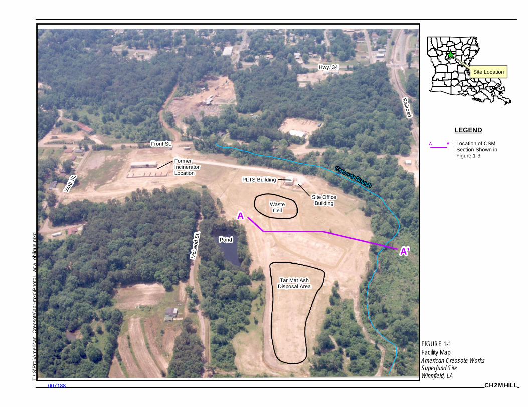
Site Location
T:\
IS\P
roj\A
mer
ican
_Cre
osot
e\a
pr-
mxd
\Pho
to1_
acw
_ob
lique
.mxd
Pond
Front St.
PLTS Building
Tar Mat AshDisposal Area
Railroad
Hwy. 34W
att S
t.
McL
eod
St.
Creosote Branch
WasteCell
Site OfficeBuilding
A
A’
FormerIncineratorLocation
FIGURE 1-1
American Creosote WorksSuperfund SiteWinnfield, LA
LEGEND
A A’ Location of CSMSection Shown inFigure 1-3
CH2MHILL
Facility Map
007188

(This page intentionally left blank)
007189
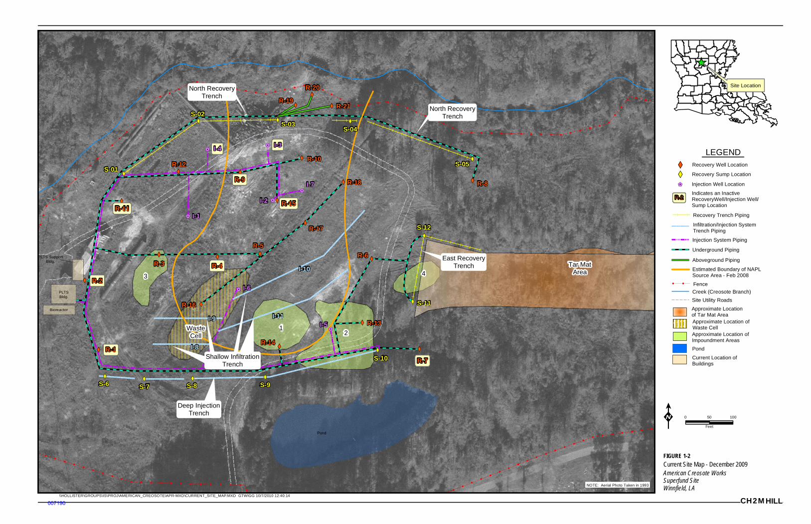
Site Location
LEGEND
PLTS SupportBldg.
PLTSBldg.
Bioreactor
Pond
I-2
R-19
R-20
R-21
I-9
I-8
I-11
I-103
WasteCell
12
4Tar Mat
Area
Deep InjectionTrench
Shallow InfiltrationTrench
East RecoveryTrench
North RecoveryTrench
North RecoveryTrench
R-7
I-5
S-9S-8S-7S-6
I-6
I-3
I-7
I-1
I-4
R-9 R-8
R-6R-5
R-4R-3
R-2
R-1S-10
S-12
S-11
S-05
S-04S-03
S-02
S-01
R-18
R-17
R-16
R-15
R-14
R-13
R-12
R-11
R-10
FIGURE 1-2
American Creosote WorksSuperfund SiteWinnfield, LA
0 10050
Feet
Recovery Well Location
Recovery Trench Piping
Injection System Piping
Underground Piping
Fence
Creek (Creosote Branch)
Pond
Current Location ofBuildings
Recovery Sump Location
Injection Well Location
NOTE: Aerial Photo Taken in 1993
Site Utility Roads
R-2Indicates an InactiveRecoveryWell/Injection Well/Sump Location
Aboveground Piping
Infiltration/Injection SystemTrench Piping
Approximate Locationof Tar Mat AreaApproximate Location ofWaste CellApproximate Location ofImpoundment Areas
Estimated Boundary of NAPLSource Area - Feb 2008
\\HOLLISTER\GROUPS\IS\PROJ\AMERICAN_CREOSOTE\APR-MXD\CURRENT_SITE_MAP.MXD GTWIGG 10/7/2010 12:40:14
CH2MHILL
Current Site Map - December 2009
007190

(This page intentionally left blank)
007191
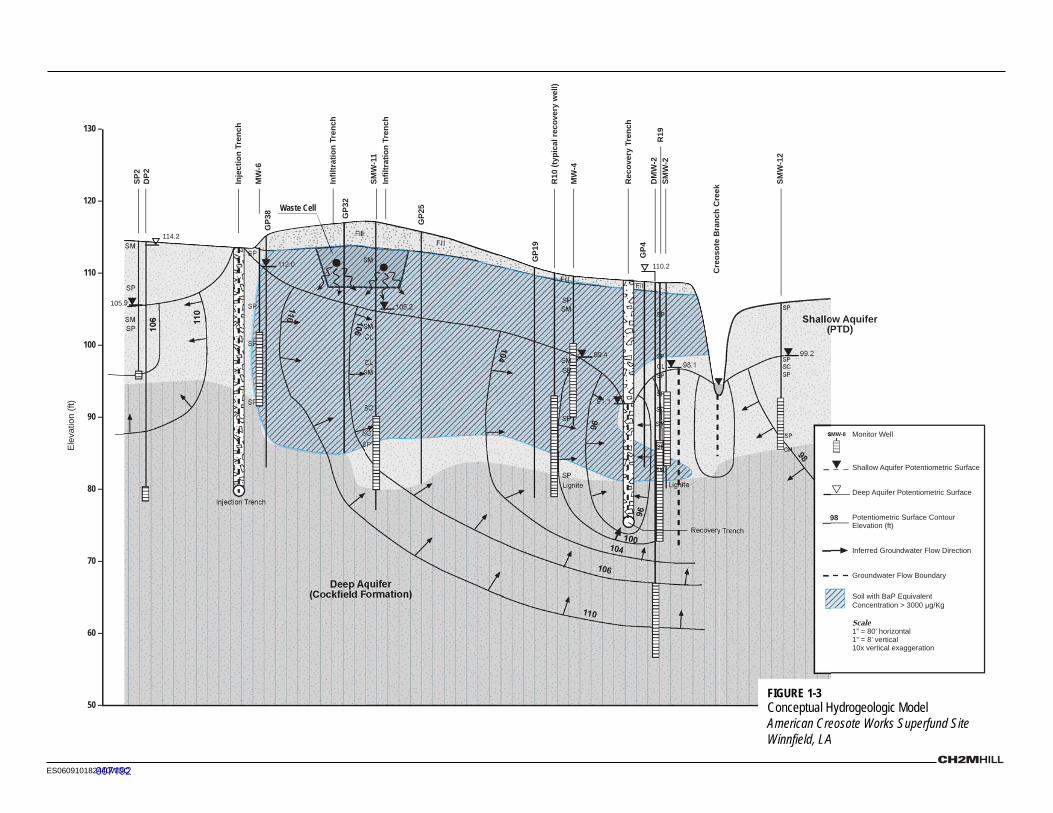
ES060910182440WDC
110
106
104104
96
106
110
100
96
98
110
106
Injection Trench
Recovery Trench
105.9
114.2
112.0
105.2
99.4
91.1
110.2
98.1
99.2
130 –
120 –
110 –
100 –
90 –
80 –
70 –
60 –
50 –
Ele
vatio
n (f
t)
(Cockfield Formation)Deep Aquifer
Shallow Aquifer(PTD)
Fill
SM
SM
SP
SP
SP
SPLignite
SM
SM
SM
CL
CL
SC
SC
SP
SM
SP
SPSM
SP
SP
SP
SP
FillFill
Fill
SP
SP
SP
CL
SP
SC
SM
SP
SM
Lignite
SP
SP
SPSC
SP
CH
Waste Cell
SP2
DP2
MW
-6
SMW
-11
Cre
osot
e B
ranc
h C
reek
SMW
-2R
19D
MW
-2
Rec
over
y Tr
ench
MW
-4
R10
(typ
ical
reco
very
wel
l)
Inje
ctio
n Tr
ench
GP3
8 GP3
2
GP2
5
GP1
9
GP4
SMW
-12
Infil
trat
ion
Tren
ch
Infil
trat
ion
Tren
ch
Monitor Well
Shallow Aquifer Potentiometric Surface
Deep Aquifer Potentiometric Surface
Potentiometric Surface ContourElevation (ft)
Inferred Groundwater Flow Direction
Groundwater Flow Boundary
Soil with BaP Equivalent Concentration > 3000 μg/Kg
Scale1” = 80’ horizontal1” = 8’ vertical10x vertical exaggeration
SMW-8
89
FIGURE 1-3 Conceptual Hydrogeologic ModelAmerican Creosote Works Superfund SiteWinnfield, LA
007192

(This page intentionally left blank)
007193
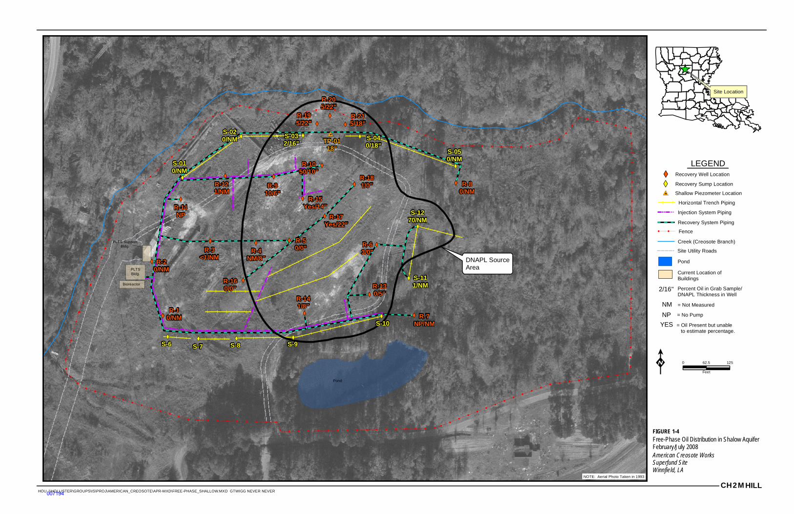
Site Location
LEGEND
CH2MHILL
PLTS SupportBldg.
PLTSBldg.
Bioreactor
Pond
R-195/22"
R-205/22"
R-215/18"
TP-0118"
DNAPL SourceArea
S-9S-8S-7S-6
R-910/6"
R-80/NM
R-7NP/NM
R-63/0"
R-50/0"R-4
NM/8"R-3
<1/NMR-2
0/NM
R-10/NM
S-10
S-1270/NM
S-111/NM
S-050/NM
S-040/18"
S-032/16"
S-020/NM
S-010/NM
R-181/0"
R-17Yes/22"
R-160/0"
R-15Yes/14"
R-141/8"
R-130/5"
R-121/NM
R-11NP
R-1050/10"
0 12562.5
Feet
Recovery Well Location
Horizontal Trench Piping
Injection System Piping
Recovery System Piping
Fence
Creek (Creosote Branch)
Pond
Current Location ofBuildings
Recovery Sump Location
Shallow Piezometer Location
NOTE: Aerial Photo Taken in 1993
Site Utility Roads
2/16" Percent Oil in Grab Sample/DNAPL Thickness in Well
= Not MeasuredNM
= No PumpNP
= Oil Present but unable to estimate percentage.
YES
FIGURE 1-4
American Creosote WorksSuperfund SiteWinnfield, LA
Free-Phase Oil Distribution in Shalow AquiferFebruary/July 2008
HOU \\HOLLISTER\GROUPS\IS\PROJ\AMERICAN_CREOSOTE\APR-MXD\FREE-PHASE_SHALLOW.MXD GTWIGG NEVER NEVER007194

(This page intentionally left blank)
007195
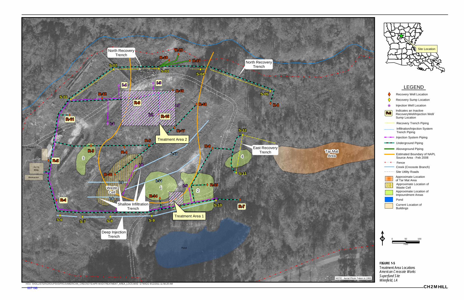
Site Location
LEGEND
PLTS SupportBldg.
PLTSBldg.
Bioreactor
Pond
R-19
R-20
R-21
I-9
I-8
I-11
I-103
WasteCell
12
4Tar Mat
Area
Deep InjectionTrench
Shallow InfiltrationTrench
East RecoveryTrench
North RecoveryTrench
North RecoveryTrench
R-7
Treatment Area 1
I-2
Treatment Area 2
I-5
S-9S-8S-7S-6
I-6
I-3
I-7
I-1
I-4
R-9 R-8
R-6R-5
R-4R-3
R-2
R-1S-10
S-12
S-11
S-05
S-04S-03
S-02
S-01
R-18
R-17
R-16
R-15
R-14
R-13
R-12
R-11
R-10
0 10050
Feet
Recovery Well Location
Recovery Trench Piping
Injection System Piping
Underground Piping
Fence
Creek (Creosote Branch)
Pond
Current Location ofBuildings
Recovery Sump Location
Injection Well Location
NOTE: Aerial Photo Taken in 1993
Site Utility Roads
R-2Indicates an InactiveRecoveryWell/Injection Well/Sump Location
Aboveground Piping
Infiltration/Injection SystemTrench Piping
Approximate Locationof Tar Mat AreaApproximate Location ofWaste CellApproximate Location ofImpoundment Areas
Estimated Boundary of NAPLSource Area - Feb 2008
HOU \\HOLLISTER\GROUPS\IS\PROJ\AMERICAN_CREOSOTE\APR-MXD\TREATMENT_AREA_LOCS.MXD GTWIGG 9/12/2011 11:56:20 AM
CH2MHILL
FIGURE 1-5
American Creosote WorksSuperfund SiteWinnfield, LA
Treatment Area Locations
007196

(This page intentionally left blank)
007197
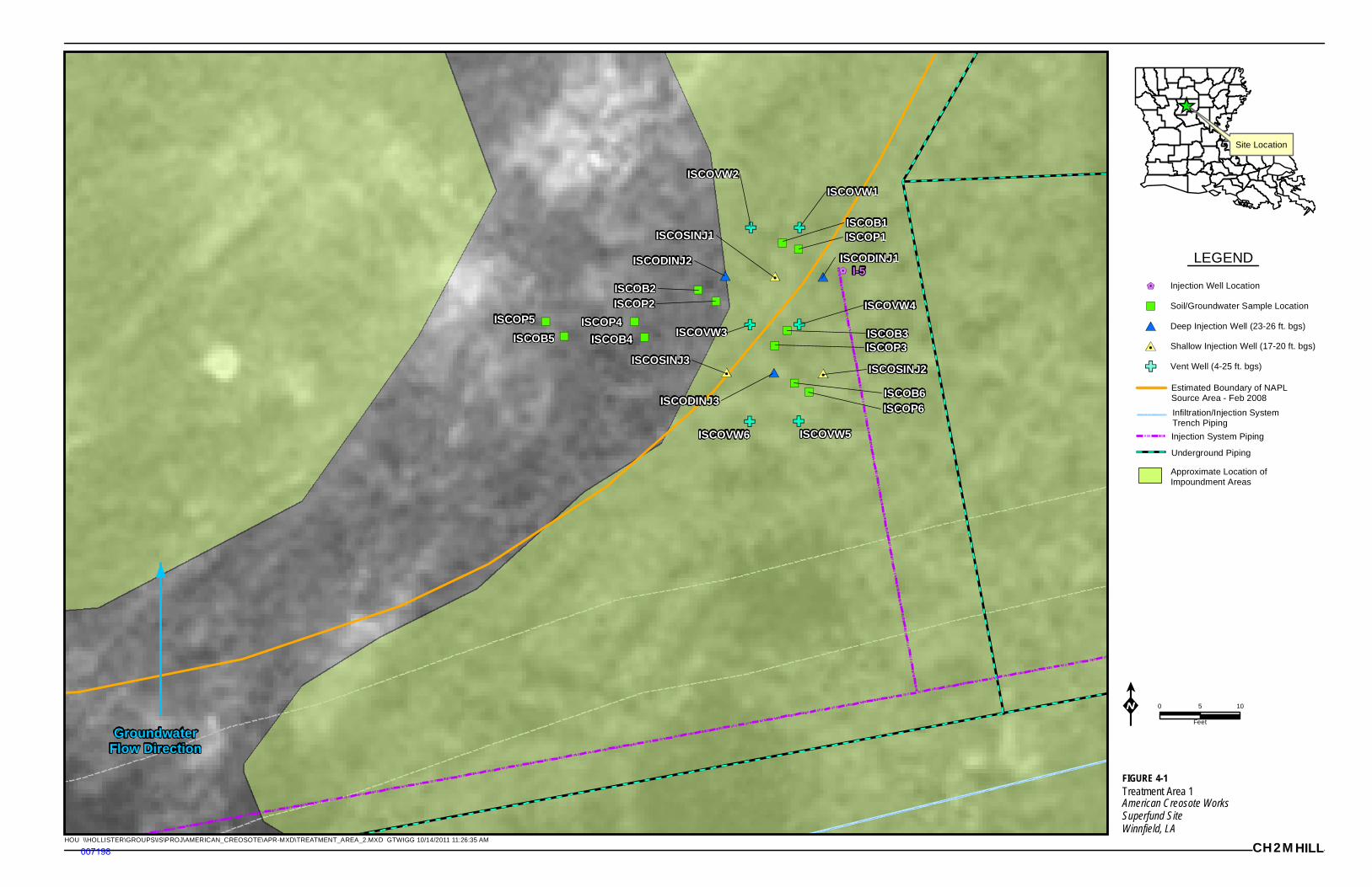
Site Location
LEGEND
ISCOB1
ISCOB3ISCOP4
ISCOB4
ISCOP5ISCOB5
ISCODINJ1
ISCOVW5ISCOVW6
ISCOP1ISCOSINJ1
ISCOB6ISCOP6ISCODINJ3
ISCOSINJ2
ISCOP3
ISCOVW4
ISCOVW1ISCOVW2
ISCODINJ2
ISCOB2ISCOP2
ISCOSINJ3
ISCOVW3
I-5
0 105
Feet
Injection System Piping
Underground Piping
Injection Well Location
Approximate Location ofImpoundment Areas
CH2MHILL
Estimated Boundary of NAPLSource Area - Feb 2008
Infiltration/Injection SystemTrench Piping
Soil/Groundwater Sample Location
Deep Injection Well (23-26 ft. bgs)
Shallow Injection Well (17-20 ft. bgs)
Vent Well (4-25 ft. bgs)
GroundwaterFlow Direction
HOU \\HOLLISTER\GROUPS\IS\PROJ\AMERICAN_CREOSOTE\APR-MXD\TREATMENT_AREA_2.MXD GTWIGG 10/14/2011 11:26:35 AM
FIGURE 4-1
American Creosote WorksSuperfund SiteWinnfield, LA
Treatment Area 1
007198

(This page intentionally left blank)
007199
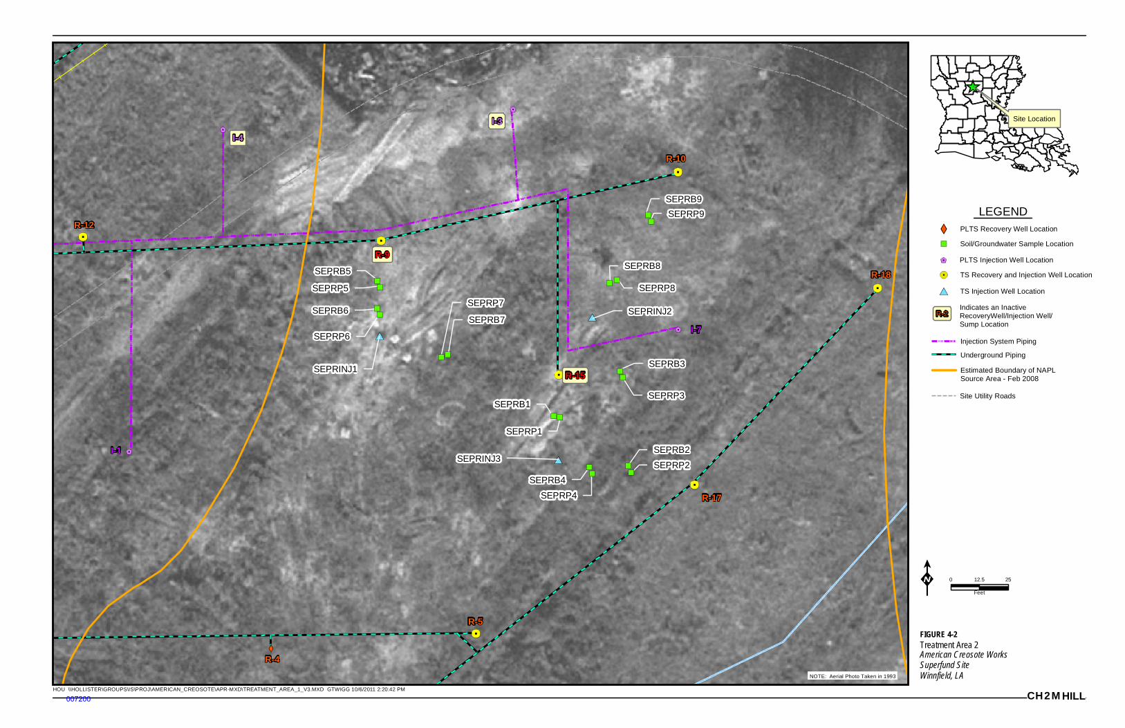
Site Location
LEGEND
R-9
R-15
SEPRB1
SEPRP1
SEPRB2
SEPRP2
SEPRB4
SEPRP4
SEPRB5
SEPRP5
SEPRB6
SEPRP6
SEPRB7
SEPRP7
SEPRB8
SEPRP8
SEPRB9
SEPRP9
SEPRB3
SEPRP3
R-18
R-12
I-4
I-3
R-10
R-17
R-5
I-7
I-1
R-4
SEPRINJ1
SEPRINJ2
SEPRINJ3
0 2512.5
Feet
PLTS Recovery Well Location
Injection System Piping
Underground Piping
PLTS Injection Well Location
NOTE: Aerial Photo Taken in 1993
Site Utility Roads
R-2Indicates an InactiveRecoveryWell/Injection Well/Sump Location
Estimated Boundary of NAPLSource Area - Feb 2008
CH2MHILL
Soil/Groundwater Sample Location
TS Recovery and Injection Well Location
HOU \\HOLLISTER\GROUPS\IS\PROJ\AMERICAN_CREOSOTE\APR-MXD\TREATMENT_AREA_1_V3.MXD GTWIGG 10/6/2011 2:20:42 PM
TS Injection Well Location
FIGURE 4-2
American Creosote WorksSuperfund SiteWinnfield, LA
Treatment Area 2
007200

(This page intentionally left blank)
007201
Appendix A Health and Safety Plan Addendum
007202

APPENDIX A: HEALTH AND SAFETY PLAN ADDENDUM
ACW_TTP_VER2.1.DOCX NOVEMBER 2011 ES111011092113DFW
(This page intentionally left blank)
007203
REMEDIAL ACTION CONTRACT
United States Environmental Protection Agency Region 6
Contract No. EP-W-06-021
Health and Safety Plan Addendum
American Creosote Works Site
Feasibility Study Winnfield, Louisiana
Task Order No. 0051-RIFS-06G3
Document Control No. 0051-02001
October 2010
In Association With: Weston Solutions Geo-Marine, Inc. E2 Consulting Engineers, Inc. Arrowhead Contracting, Inc.
007204

AMERICAN CREOSOTE WORKS SITE, FEASIBILITY STUDY HEALTH AND SAFETY PLAN
ADDENDUM
2010 ES TT STUDY HSP ADDENDUM AMERICAN CREOSOTE.DOC OCTOBER 2010 ES101410012121DFW\102870012
(This page intentionally left blank)
007205
2010 ES TT STUDY HSP ADDENDUM AMERICAN CREOSOTE.DOC OCTOBER 2010 ES101410012121DFW\102870012
American Creosote Works Site Feasibility Study
Health and Safety Plan Addendum
Prepared for
U.S. Environmental Protection Agency Contract No. EP-W-06-021
Task Order 0051-RIFS-06G3 CH2M HILL Project No. 411242
DCN 0051-02001
October 2010
12377 Merit Drive
Dallas, Texas 75251
007206

AMERICAN CREOSOTE WORKS SITE, FEASIBILITY STUDY HEALTH AND SAFETY PLAN
ADDENDUM
2010 ES TT STUDY HSP ADDENDUM AMERICAN CREOSOTE.DOC OCTOBER 2010 ES101410012121DFW\102870012
(This page intentionally left blank)
007207
2010 ES TT STUDY HSP ADDENDUM AMERICAN CREOSOTE.DOC V OCTOBER 2010 ES101410012121DFW\102870012
Contents
Section Page
Approval ................................................................................................................................... vii
1 Introduction ......................................................................................................................... 1-1
2 Applicability ....................................................................................................................... 2-1
3 General Project Information ............................................................................................ 3-1 3.1 Project Information and Background .................................................................. 3-1
3.1.1 General Wastes and Waste Volumes ...................................................... 3-2 3.1.2 Present Status and Issues ......................................................................... 3-3 3.1.3 CH2M HILL Project Activities ................................................................ 3-3
3.2 Site Background and Setting ................................................................................. 3-4 3.3 Description of Tasks ............................................................................................... 3-4
3.3.1 Hazwoper-Regulated Tasks ..................................................................... 3-4 3.3.2 Non-Hazwoper-Regulated Tasks ........................................................... 3-5
4 Project Organization and Responsibilities ................................................................... 4-1 4.1 Client ...................................................................................................................... 4-1 4.2 CH2M HILL ............................................................................................................ 4-1 4.3 CH2M HILL Subcontractors ................................................................................. 4-1 4.4 Employee Responsibilities .................................................................................... 4-2 4.5 Client Contractors .................................................................................................. 4-2
5 Standards of Conduct ........................................................................................................ 5-1
6 Safety Planning and Change Management ................................................................... 6-1
7 Project Hazard Analysis .................................................................................................... 7-1 7.1 Activity Hazard Analysis ...................................................................................... 7-1 7.2 Subcontractor Activity Hazard Analysis ............................................................ 7-1
8 General Hazards and Controls ........................................................................................ 8-1
9 Project-Specific Hazard Controls .................................................................................... 9-1 9.1 S-ISCO® Chemical Delivery ................................................................................. 9-1 9.2 S-ISCO® Chemical Injection and Process Monitoring ...................................... 9-1
10 Physical Hazards and Controls ...................................................................................... 10-1
11 Biological Hazards and Controls ................................................................................... 11-1
12 Contaminants of Concern ............................................................................................... 12-1
13 Site Monitoring ................................................................................................................. 13-1
14 Personal Protective Equipment ..................................................................................... 14-1 14.1 Required Personal Protective Equipment ......................................................... 14-1 14.2 Respiratory Protection ......................................................................................... 14-3
007208
CONTENTS
2010 ES TT STUDY HSP ADDENDUM AMERICAN CREOSOTE.DOC VI OCTOBER 2010 ES101410012121DFW\102870012
15 Worker Training and Qualification .............................................................................. 15-1
16 Medical Surveillance and Qualification ...................................................................... 16-1
17 Site-Control Plan .............................................................................................................. 17-1
18 Decontamination .............................................................................................................. 17-1
19 Emergency Response Plan .............................................................................................. 19-1 19.1 Pre-Emergency Planning ..................................................................................... 19-1 19.2 Emergency Equipment and Supplies ................................................................ 19-2 19.3 Incident Response ................................................................................................ 19-2 19.4 Emergency Medical Treatment .......................................................................... 19-2 19.5 Evacuation ............................................................................................................. 19-3 19.6 Evacuation Signals ............................................................................................... 19-3 19.7 Inclement Weather ............................................................................................... 19-3
20 Spill Containment Procedures ....................................................................................... 20-1 20.1 Additional ISCO Spill Containment Procedures ............................................. 20-1
20.1.1 Hydrogen Peroxide Spill: ....................................................................... 20-2 20.1.2 Sulfuric or Phosphoric Acid Spill:......................................................... 20-2 20.1.3 Ferrous Sulfate or Calcium Phosphate Spill: ....................................... 20-2
20.2 Additional S-EPR/S-ISCO Spill Containment Procedures ............................ 20-2
21 Inspections ......................................................................................................................... 21-1 21.1 Project Activity Self-Assessment Checklists .................................................... 21-1 21.2 Safe Behavior Observations ................................................................................ 21-1
22 Incident Notification, Reporting, and Investigation ................................................. 22-1
23 Records and Reports ........................................................................................................ 23-1 Tables
7-1 Task Hazard Analysis 14-1 PPE Specifications 14-2 Respirator Change-Out Schedule
Figures
3-1 Site Map
Attachments
1 Employee Signoff Form – Health and Safety Plan 2 Chemical Inventory/Register Form 3 Chemical-Specific Training Form 4 Project Activity Self-Assessment Checklists/Forms/Permits 5 Behavior Based Loss Prevention System Forms 6 Material Safety Data Sheets 7 Working Alone Standard 8 Tick Fact Sheet 9 Observed Hazard Form
007209
2010 ES TT STUDY HSP ADDENDUM AMERICAN CREOSOTE.DOC VII OCTOBER 2010
ES101410012121DFW\102870012
Approval Sheet
This site-specific Health and Safety Plan (HSP) Addendum has been written for use by CH2M HILL only. CH2M HILL claims no responsibility for its use by others unless that use has been specified and defined in project or contract documents. The plan is written for the specific site conditions and identified scope(s) of work and must be amended if those conditions or scope(s) of work change.
By approving this HSP, the Responsible Health and Safety Manager (RHSM) certifies that the personal protective equipment has been selected based on the project-specific hazard assessment.
Original Plan
RHSM Approval: Date:
Field Operations Manager Approval: Date:
Revisions
Revisions Made By: Date:
Description of Revisions to Plan:
Revisions Approved By: Date:
007210

APPROVAL SHEET
2010 ES TT STUDY HSP ADDENDUM AMERICAN CREOSOTE.DOC VIII OCTOBER 2010 ES101410012121DFW\102870012
(This page intentionally left blank)
007211

2010 ES TT STUDY HSP ADDENDUM AMERICAN CREOSOTE.DOC 1-1 OCTOBER 2010 ES101410012121DFW\102870012
SECTION 1
Introduction
This Addendum to the Health and Safety Plan (HSP) American Creosote Works (CH2M HILL, 2010) was developed to address Treatability Study specific activities not already covered in the HSP. For complete understanding of the health and safety issues at the site, both documents must be used.
007212

SECTION 1: 0BINTRODUCTION
2010 ES TT STUDY HSP ADDENDUM AMERICAN CREOSOTE.DOC 1-2 OCTOBER 2010 ES101410012121DFW\102870012
(This page intentionally left blank)
007213
2010 ES TT STUDY HSP ADDENDUM AMERICAN CREOSOTE.DOC 2-1 OCTOBER 2010 ES101410012121DFW\102870012
SECTION 2
Applicability
See the HSP American Creosote Works (CH2M HILL, 2010).
007214

SECTION 2: APPLICABILITY
2010 ES TT STUDY HSP ADDENDUM AMERICAN CREOSOTE.DOC 2-2 OCTOBER 2010 ES101410012121DFW\102870012
(This page intentionally left blank)
007215
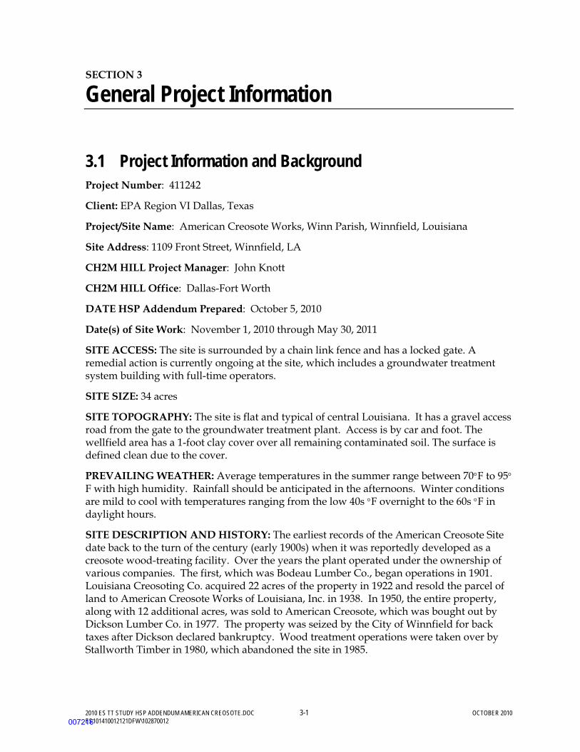
2010 ES TT STUDY HSP ADDENDUM AMERICAN CREOSOTE.DOC 3-1 OCTOBER 2010 ES101410012121DFW\102870012
SECTION 3
General Project Information
3.1 Project Information and Background Project Number: 411242
Client: EPA Region VI Dallas, Texas
Project/Site Name: American Creosote Works, Winn Parish, Winnfield, Louisiana
Site Address: 1109 Front Street, Winnfield, LA
CH2M HILL Project Manager: John Knott
CH2M HILL Office: Dallas-Fort Worth
DATE HSP Addendum Prepared: October 5, 2010
Date(s) of Site Work: November 1, 2010 through May 30, 2011
SITE ACCESS: The site is surrounded by a chain link fence and has a locked gate. A remedial action is currently ongoing at the site, which includes a groundwater treatment system building with full-time operators.
SITE SIZE: 34 acres
SITE TOPOGRAPHY: The site is flat and typical of central Louisiana. It has a gravel access road from the gate to the groundwater treatment plant. Access is by car and foot. The wellfield area has a 1-foot clay cover over all remaining contaminated soil. The surface is defined clean due to the cover.
PREVAILING WEATHER: Average temperatures in the summer range between 70°F to 95°F with high humidity. Rainfall should be anticipated in the afternoons. Winter conditions are mild to cool with temperatures ranging from the low 40s °F overnight to the 60s °F in daylight hours.
SITE DESCRIPTION AND HISTORY: The earliest records of the American Creosote Site date back to the turn of the century (early 1900s) when it was reportedly developed as a creosote wood-treating facility. Over the years the plant operated under the ownership of various companies. The first, which was Bodeau Lumber Co., began operations in 1901. Louisiana Creosoting Co. acquired 22 acres of the property in 1922 and resold the parcel of land to American Creosote Works of Louisiana, Inc. in 1938. In 1950, the entire property, along with 12 additional acres, was sold to American Creosote, which was bought out by Dickson Lumber Co. in 1977. The property was seized by the City of Winnfield for back taxes after Dickson declared bankruptcy. Wood treatment operations were taken over by Stallworth Timber in 1980, which abandoned the site in 1985.
007216

SECTION 3: GENERAL PROJECT INFORMATION
2010 ES TT STUDY HSP ADDENDUM AMERICAN CREOSOTE.DOC 3-2 OCTOBER 2010 ES101410012121DFW\102870012
During the operating history of the plant, there were apparently numerous releases of creosote and creosote- bearing wastes onto the site and into a series of pits connected to a neighboring creek. Sources of contamination at the site include five unlined pits used for the disposal of wastes generated by the wood-treating process, storage areas containing creosote, treated and untreated wood, and the plant at which the wood-treating operations took place. Contamination was also caused by discharges into onsite drainage ditches that received surface water run-off from the facility. The site was included on the National Priorities List by the EPA in 1992 with a HRS Score of 50.70. A Remedial Investigation (RI) was conducted in 1992, the Feasibility Study (FS) was completed in 1992, and the Record of Decision was signed on April 28, 1993.
The remedial action contract for incineration, bio-remediation of waste left in place, and pump-and-treat of the ground water was signed in June 1994. The U.S. Army Corps of Engineers (USACE) resident office was established at the site in December 1994. The USACE was the contracting officer for EPA during construction. The remedial design was completed in May 1996 and the onsite mobile incinerator was installed and tested in December 1996. The incineration phase for the 25,000 cubic yards of heavily contaminated material was completed in February 1998.
Construction of the fluids extraction and treatment system (PLTS) was completed and operations commenced in October 1996. The system has operated continuously since October 1996 recovering approximately 192,000 gallons of creosote and creosote emulsion from 79 million gallons of total fluids pumped. The system is expected to operate for the foreseeable future.
CH2M HILL assumed responsibility for site operations on September 30, 1999, hiring the onsite staff from IT Corporation when the contract was transferred.
3.1.1 General Wastes and Waste Volumes The principal contaminants in site soil include pentachlorophenol (PCP) detected at concentrations up to 6,000 parts per million (ppm) in tar residue, and carcinogenic polynuclear aromatic hydrocarbons (PAHs) detected at concentrations up to 500 ppm. These are pre-treatment concentrations and such values would only be found today in the waste material lying beneath the clay cover undergoing treatment via in situ bioremediation. Groundwater contaminants are of the same type with total PAH concentrations ranging from less than 0.0002 ppm to 100 ppm, PCP concentrations ranging from less than 0.05 ppm to 0.9 ppm, and total benzene, toluene, ethylbenzene and xylene (BTEX) concentrations ranging from less than 0.001 parts per billion (ppb) to 150 ppb. Benzene concentrations generally range from less than 0.001 ppm to 0.3 ppm. Several recovery wells and trench sumps also contain free-phase creosote. Additional information on these contaminants is provided in Section 2.5.
Remedial actions conducted since 1993 include excavation and incineration of 25,000 cubic yards of heavily contaminated soil from Tar Mat area, consolidation of less contaminated surface soil in Waste Cell area, and installation of a fluids (groundwater and free phase oil) extraction and treatment system. Deep subsurface contaminated soil and material consolidated in the Waste Cell is currently undergoing in situ biodegradation treatment. The fluids extraction and treatment system will address approximately 24 million gallons of contaminated ground water and 400,000 gallons of immobile and free phase creosote
007217
SECTION 3: GENERAL PROJECT INFORMATION
2010 ES TT STUDY HSP ADDENDUM AMERICAN CREOSOTE.DOC 3-3 OCTOBER 2010 ES101410012121DFW\102870012
product within the shallow aquifer, present at depths between about 15 and 30 feet below ground surface.
3.1.2 Present Status and Issues The U. S. Environmental Protection Agency, Region 6 (EPA) has retained CH2M HILL, Inc., under the EPA Region 6 Response Action Contract EP-W-06-021, Task Order No. 0042, to perform Treatability Study (TT) activities. The TT Study consists of three tests: in-situ chemical oxidation (ISCO), surfactant-enhanced product removal (SEPR) product removal, and in-situ stabilization. The objective of the TT study is to evaluate performance of three technologies (ISCO, SEPR, and stabilization) to address areas of residual (immobile) and/or mobile DNAPL present at the Site.
Process monitoring and data recording during the ISCO injection will be conducted by Geocleanse International, Inc. (GCI). Similarly, the SEPR/S-ISCO test field work will be conducted by VeruTEK and Evergreen Resources Group Inc. (ERGI) with oversite by CH2M HILL.
3.1.3 CH2M HILL Project Activities CH2M HILL project activities during the TT Study will include operation and maintenance (O&M) of the PLTS, fluid extraction equipment (wells, trench and pumps) and bioremediation, chemical oxidation, and surfactant injection systems (wells and trench), site maintenance and security, performance monitoring, well installation, and subsurface investigation. This work generally requires the following field activities:
Normal Operations
• Monitoring and injection well sampling/bailing, extraction wellhead sampling, and water level measurements
• PLTS and tank liquids sampling
• On-going PLTS operational tasks
− Tank/Bioreactor water level checks/meter readings − Pumping down sludge/lamella/NAPL concentrator tanks − Transfer of recovered creosote (NAPL) from storage tank to tanker transfer truck.
• Handling/mixing pilot test chemicals: hydrogen peroxide, and surfactant-enhanced product recovery chemicals.
• Monitor well and piezometer installation, subsurface investigations (soil borings),
• Surface water and sediment sampling, stormwater sampling, biosolids sampling.
Maintenance Operations
• Well system equipment repairs/replacements (pumps and piping) • PLTS and pilot test equipment repairs/replacement • Electrical/pumps and motor repair • Oil/water separator drive chain repair • Sand/carbon filter change-out
007218
SECTION 3: GENERAL PROJECT INFORMATION
2010 ES TT STUDY HSP ADDENDUM AMERICAN CREOSOTE.DOC 3-4 OCTOBER 2010 ES101410012121DFW\102870012
• Grounds maintenance (mowing and trimming) that includes heavy and light equipment operation
3.2 Site Background and Setting A current map of the ACW site and TT Study locations are provided in Figure 1-2 and 1-4 of the main text.
3.3 Description of Tasks Refer to project documents (i.e., Field Sampling Plan, Quality Assurance Project Plan, Site Management Plan, and TT Study Plan and other site-specific plans) for detailed task information. A health and safety risk analysis (Section 1.2) has been performed for each task and is incorporated in this plan through task-specific hazard controls and requirements for monitoring and protection. Additional TT Study activities require an approved amendment or revision to this plan before tasks begin. Subcontractors will provide these additional task-specific hazard controls and requirements prior to TT Study activities. Refer to Section 3.3.2 for procedures related to “clean” tasks that do not involve hazardous waste operations and emergency response (Hazwoper).
3.3.1 Hazwoper-Regulated Tasks The Treatability Study will be comprised of several phases of work, performed by CH2M Hill and Subcontractors including:
• Pre-test mobilization activities • Baseline sampling • Technology testing • Performance sampling
The following tasks will be included in each phase:
Pre-Test Operations • Monitoring, vent/recovery and piezometer
installation • Well system equipment repairs/replacements
(pumps and piping) • Plumbing of existing system wells to pilot
testing equipment • Well rehabilitation activities, including
injection of preliminary S-EPRTM • Staging of frac tanks, water level checks,
storage and sampling of well rehabilitation groundwater
Technology Testing Operations • Handling/mixing pilot test chemicals:
hydrogen peroxide, S-EPRTM, and S-ISCO® • Load-out and decon of NAPL and chemical
storage tanks • Tank water level measurements • PLTS and pilot test equipment
repairs/replacement • Transfer of contaminant laden groundwater
Baseline and Performance Testing Operations
• Subsurface soil and groundwater sampling • DNAPL sample collection
007219

SECTION 3: GENERAL PROJECT INFORMATION
2010 ES TT STUDY HSP ADDENDUM AMERICAN CREOSOTE.DOC 3-5 OCTOBER 2010 ES101410012121DFW\102870012
3.3.2 Non-Hazwoper-Regulated Tasks Under specific circumstances, the training and medical monitoring requirements of federal or state Hazwoper regulations are not applicable. It must be demonstrated that the tasks can be performed without the possibility of exposure in order to use non-Hazwoper-trained personnel. Contact the Responsible Health and Safety Manager prior to using non-Hazwoper-trained personnel for the following tasks when working on a regulated hazardous waste site.
Tasks Controls
• Utility locate activities • A trained Hazwoper person must be onsite during these actions • Surveying TT Study Areas
• Onsite administration (billing, reporting, training)
007220
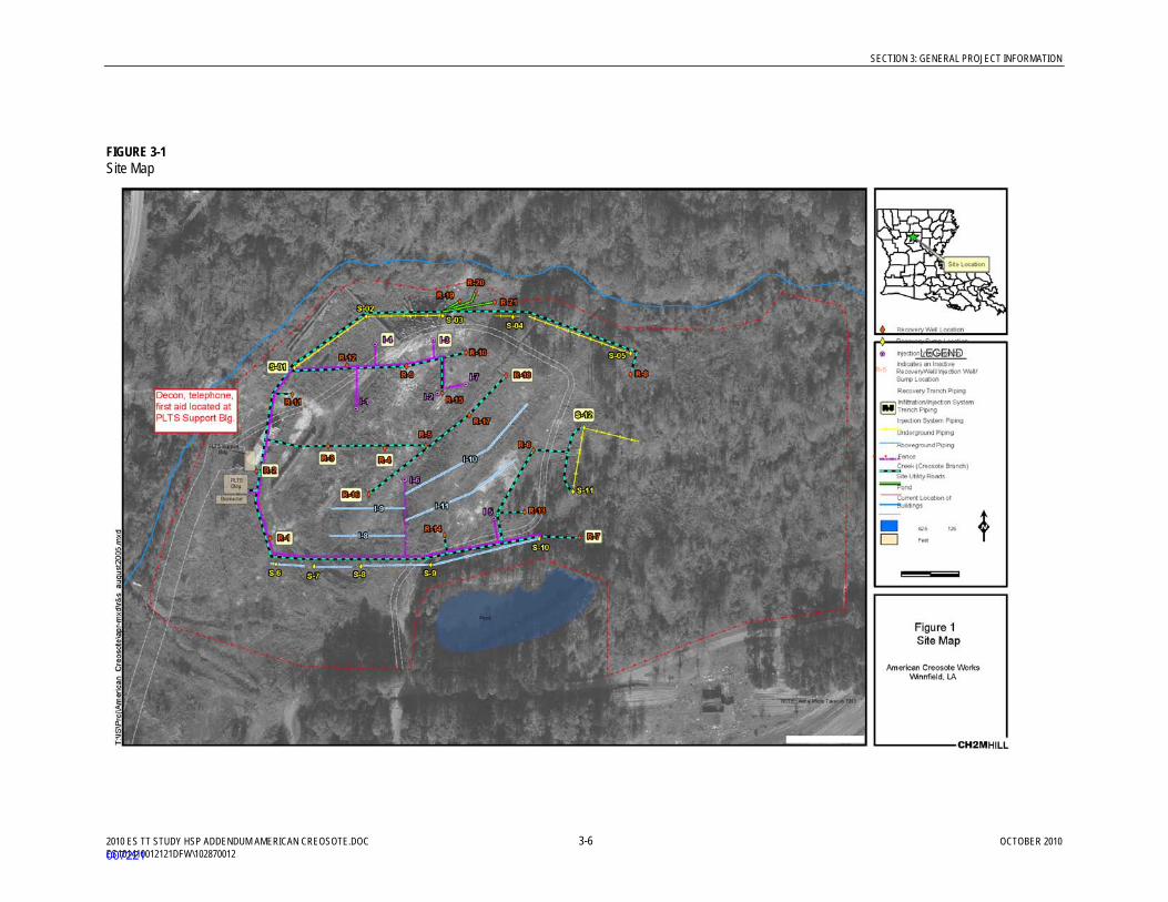
SECTION 3: GENERAL PROJECT INFORMATION
2010 ES TT STUDY HSP ADDENDUM AMERICAN CREOSOTE.DOC 3-6 OCTOBER 2010 ES101410012121DFW\102870012
FIGURE 3-1 Site Map
007221
2010 ES TT STUDY HSP ADDENDUM AMERICAN CREOSOTE.DOC 4-1 OCTOBER 2010
ES101410012121DFW\102870012
SECTION 4
Project Organization and Responsibilities
4.1 Client
See the HSP American Creosote Works (CH2M HILL, 2010).
4.2 CH2M HILL
See the HSP American Creosote Works (CH2M HILL, 2010).
4.3 CH2M HILL Subcontractors
(Reference CH2M HILL SOP HSE-215, Contracts and Subcontracts)
CH2M HILL subcontractors performing onsite Hazwoper activities for the TT Study include VeruTEK, Evergreen Resources Group Inc. (ERGI), and Geo-Cleanse International, Inc (GCI). Associated personnel provide drilling, injection and extraction oversite, performance evaluation, and groundwater monitoring support. From time to time, subcontractors may be contracted to support specific activities, such as surveying or transportation and disposal. When this occurs, the subcontract terms and conditions require subcontractor staff to adhere to the CH2M HILL HSP and addendums.
Subcontractors must comply with the following activities, and are responsible to:
• Comply with all local, state, and federal safety standards;
• Comply with project and owner safety requirements;
• Actively participate in the project safety program and either hold or attend and participate in all required safety meetings;
• Provide a qualified safety representative to interface with CH2M HILL;
• Maintain safety equipment and PPE for their employees;
• Maintain and replace safety protection systems damaged or removed by the subcontractor’s operations;
• Notify the SC of any accident, injury, or incident immediately and submit reports to CH2M HILL within 24 hours;
• Install contractually required general conditions for safety (for example, handrail, fencing, fall protection systems, floor opening covers);
• Conduct and document weekly safety inspections of project-specific tasks and associated work areas;
007222
SECTION 4: PROJECT ORGANIZATION AND RESPONSIBILITIES
2010 ES TT STUDY HSP ADDENDUM AMERICAN CREOSOTE.DOC 4-2 OCTOBER 2010 ES101410012121DFW\102870012
• Conduct site-specific and job-specific training for all subcontractor employees, including review of the CH2M HILL HSP, subcontractor HSPs, and subcontractor AHAs and sign appropriate sign-off forms; and
• Determine and implement necessary controls and corrective actions to correct unsafe conditions.
The subcontractors listed above may be required to submit their own site-specific HSP and other plans such as lead or asbestos abatement compliance plans. Subcontractors are responsible for the health and safety procedures specific to their work, and are required to submit their plans to CH2M HILL for review and acceptance before the start of field work.
Subcontractors are also required to prepare AHAs before beginning each activity posing hazards to their personnel. The AHA shall identify the principle steps of the activity, potential health and safety hazards for each step and recommended control measures for each identified hazard. In addition, a listing of the equipment to be used to perform the activity, inspection requirements, and training requirements for the safe operation of the equipment listed must be identified.
4.4 Employee Responsibilities See the HSP American Creosote Works (CH2M HILL, 2010).
4.5 Client Contractors See the HSP American Creosote Works (CH2M HILL, 2010).
007223

2010 ES TT STUDY HSP ADDENDUM AMERICAN CREOSOTE.DOC 5-1 OCTOBER 2010 ES101410012121DFW\102870012
SECTION 5
Standards of Conduct
See the HSP American Creosote Works (CH2M HILL, 2010).
007224

SECTION 5: STANDARDS OF CONDUCT
2010 ES TT STUDY HSP ADDENDUM AMERICAN CREOSOTE.DOC 5-2 OCTOBER 2010 ES101410012121DFW\102870012
(This page intentionally left blank)
007225

2010 ES TT STUDY HSP ADDENDUM AMERICAN CREOSOTE.DOC 6-1 OCTOBER 2010 ES101410012121DFW\102870012
SECTION 6
Safety Planning and Change Management
See the HSP American Creosote Works (CH2M HILL, 2010).
007226

SECTION 6: SAFETY PLANNING AND CHANGE MANAGEMENT
2010 ES TT STUDY HSP ADDENDUM AMERICAN CREOSOTE.DOC 6-2 OCTOBER 2010 ES101410012121DFW\102870012
(This page intentionally left blank)
007227
2010 ES TT STUDY HSP ADDENDUM AMERICAN CREOSOTE.DOC 7-1 OCTOBER 2010 ES101410012121DFW\102870012
SECTION 7
Project Hazard Analysis
See the HSP American Creosote Works (CH2M HILL, 2010).
7.1 Activity Hazard Analysis See the HSP American Creosote Works (CH2M HILL, 2010).
7.2 Subcontractor Activity Hazard Analysis CH2M HILL subcontractors are required to provide AHAs specific to their scope of work on the project for acceptance by CH2M HILL. Each subcontractor shall submit AHAs for their field activities, as defined in their scope of work, along with their project-specific safety plan and/or procedures. Additions or changes in field activities, equipment, tools, or material used to perform work or hazards not addressed in existing AHAs requires either a new AHA to be prepared or an existing AHA to be revised.
The following AHAs have been provided by Subcontractors and are appended to this HSP as Appendix 6:
• Process Monitoring • Vacuum Truck Operation • Well Installation • Injection of Peroxide
007228
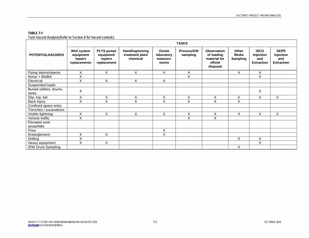
SECTION 7: PROJECT HAZARD ANALYSIS
2010 ES TT STUDY HSP ADDENDUM AMERICAN CREOSOTE.DOC 7-2 OCTOBER 2010 ES101410012121DFW\102870012
TABLE 7-1 Task Hazard Analysis(Refer to Section 8 for hazard controls)
POTENTIALHAZARDS
TASKS
Well system equipment
repairs replacements
PLTS pump/ equipment
repairs replacement
Handling/mixing treatment plant
chemical
Onsite laboratory measure-
ments
Process/GW sampling
Observation of loading
material for offsite
disposal
Other Media
Sampling
ISCO Injection
and Extraction
SEPR Injection
and Extraction
Flying debris/objects X X X X X X X Noise > 85dBA X X X Electrical X X X X Suspended loads Buried utilities, drums, tanks X X
Slip, trip, fall X X X X X X X X X Back injury X X X X X X X Confined space entry Trenches / excavations Visible lightning X X X X X X X X X Vehicle traffic X X X Elevated work areas/falls
Fires X Entanglement X X X Drilling X X X Heavy equipment X X X IDW Drum Sampling X
007229

2010 ES TT STUDY HSP ADDENDUM AMERICAN CREOSOTE.DOC 8-1 OCTOBER 2010 ES101410012121DFW\102870012
SECTION 8
General Hazards and Controls
See the HSP American Creosote Works (CH2M HILL, 2010).
007230

SECTION 8: GENERAL HAZARDS AND CONTROLS
2010 ES TT STUDY HSP ADDENDUM AMERICAN CREOSOTE.DOC 8-2 OCTOBER 2010 ES101410012121DFW\102870012
(This page intentionally left blank)
007231
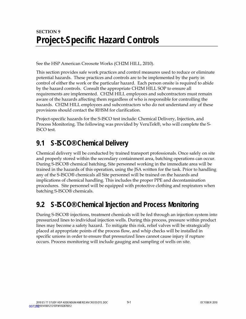
2010 ES TT STUDY HSP ADDENDUM AMERICAN CREOSOTE.DOC 9-1 OCTOBER 2010 ES101410012121DFW\102870012
SECTION 9
Project-Specific Hazard Controls
See the HSP American Creosote Works (CH2M HILL, 2010).
This section provides safe work practices and control measures used to reduce or eliminate potential hazards. These practices and controls are to be implemented by the party in control of either the work or the particular hazard. Each person onsite is required to abide by the hazard controls. Consult the appropriate CH2M HILL SOP to ensure all requirements are implemented. CH2M HILL employees and subcontractors must remain aware of the hazards affecting them regardless of who is responsible for controlling the hazards. CH2M HILL employees and subcontractors who do not understand any of these provisions should contact the RHSM for clarification.
Project-specific hazards for the S-ISCO test include: Chemical Delivery, Injection, and Process Monitoring. The following was provided by VeruTek®, who will complete the S-ISCO test.
9.1 S-ISCO® Chemical Delivery Chemical delivery will be conducted by trained transport professionals. Once safely on site and properly stored within the secondary containment area, batching operations can occur. During S-ISCO® chemical batching, Site personnel working in the immediate area will be trained in the hazards of this operation, using the JSA written for the task. Prior to handling any of the S-ISCO® chemicals all Site personnel will be trained on the hazards and implications of chemical handling. This includes the proper PPE and decontamination procedures. Site personnel will be equipped with protective clothing and respirators when batching S-ISCO® chemicals.
9.2 S-ISCO® Chemical Injection and Process Monitoring During S-ISCO® injections, treatment chemicals will be fed through an injection system into pressurized lines to individual injection wells. During this process, pressure within product lines may become a safety hazard. To mitigate this risk, relief valves will be strategically placed at appropriate points of the process flow, and whip checks will be installed in specific unions in order to ensure that pressurized lines cannot cause injury if rupture occurs. Process monitoring will include gauging and sampling of wells on site.
007232

SECTION 9: PROJECT-SPECIFIC HAZARD CONTROLS
2010 ES TT STUDY HSP ADDENDUM AMERICAN CREOSOTE.DOC 9-2 OCTOBER 2010 ES101410012121DFW\102870012
(This page intentionally left blank)
007233

2010 ES TT STUDY HSP ADDENDUM AMERICAN CREOSOTE.DOC 10-1 OCTOBER 2010 ES101410012121DFW\102870012
SECTION 10
Physical Hazards and Controls
See the HSP American Creosote Works (CH2M HILL, 2010).
007234

SECTION 10: PHYSICAL HAZARDS AND CONTROLS
2010 ES TT STUDY HSP ADDENDUM AMERICAN CREOSOTE.DOC 10-2 OCTOBER 2010 ES101410012121DFW\102870012
(This page intentionally left blank)
007235

2010 ES TT STUDY HSP ADDENDUM AMERICAN CREOSOTE.DOC 11-1 OCTOBER 2010 ES101410012121DFW\102870012
SECTION 11
Biological Hazards and Controls
See the HSP American Creosote Works (CH2M HILL, 2010).
007236

SECTION 11: BIOLOGICAL HAZARDS AND CONTROLS
2010 ES TT STUDY HSP ADDENDUM AMERICAN CREOSOTE.DOC 11-2 OCTOBER 2010 ES101410012121DFW\102870012
(This page intentionally left blank)
007237

2010 ES TT STUDY HSP ADDENDUM AMERICAN CREOSOTE.DOC 12-1 OCTOBER 2010 ES101410012121DFW\102870012
SECTION 12
Contaminants of Concern
See the HSP American Creosote Works (CH2M HILL, 2010).
007238

SECTION 12: CONTAMINANTS OF CONCERN
2010 ES TT STUDY HSP ADDENDUM AMERICAN CREOSOTE.DOC 12-2 OCTOBER 2010 ES101410012121DFW\102870012
(This page intentionally left blank)
007239

2010 ES TT STUDY HSP ADDENDUM AMERICAN CREOSOTE.DOC 13-1 OCTOBER 2010 ES101410012121DFW\102870012
SECTION 13
Site Monitoring
See the HSP American Creosote Works (CH2M HILL, 2010).
007240

SECTION 13: SITE MONITORING
2010 ES TT STUDY HSP ADDENDUM AMERICAN CREOSOTE.DOC 13-2 OCTOBER 2010 ES101410012121DFW\102870012
(This page intentionally left blank)
007241
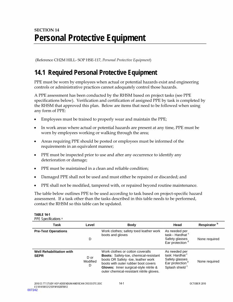
2010 ES TT STUDY HSP ADDENDUM AMERICAN CREOSOTE.DOC 14-1 OCTOBER 2010 ES101410012121DFW\102870012
SECTION 14
Personal Protective Equipment
(Reference CH2M HILL- SOP HSE-117, Personal Protective Equipment)
14.1 Required Personal Protective Equipment PPE must be worn by employees when actual or potential hazards exist and engineering controls or administrative practices cannot adequately control those hazards.
A PPE assessment has been conducted by the RHSM based on project tasks (see PPE specifications below). Verification and certification of assigned PPE by task is completed by the RHSM that approved this plan. Below are items that need to be followed when using any form of PPE:
• Employees must be trained to properly wear and maintain the PPE;
• In work areas where actual or potential hazards are present at any time, PPE must be worn by employees working or walking through the area;
• Areas requiring PPE should be posted or employees must be informed of the requirements in an equivalent manner;
• PPE must be inspected prior to use and after any occurrence to identify any deterioration or damage;
• PPE must be maintained in a clean and reliable condition;
• Damaged PPE shall not be used and must either be repaired or discarded; and
• PPE shall not be modified, tampered with, or repaired beyond routine maintenance.
The table below outlines PPE to be used according to task based on project-specific hazard assessment. If a task other than the tasks described in this table needs to be performed, contact the RHSM so this table can be updated.
TABLE 14-1 PPE Specifications a
Task Level Body Head Respirator b
Pre-Test Operations
D
Work clothes; safety toed leather work boots and gloves
As needed per task-- Hardhat c Safety glasses Ear protection d
None required
Well Rehabilitation with SEPR D or
Modified D
Work clothes or cotton coveralls Boots: Safety-toe, chemical-resistant boots OR Safety -toe, leather work boots with outer rubber boot covers Gloves: Inner surgical-style nitrile & outer chemical-resistant nitrile gloves.
As needed per task: Hardhat c Safety glasses Ear protection d
Splash shield c
None required
007242
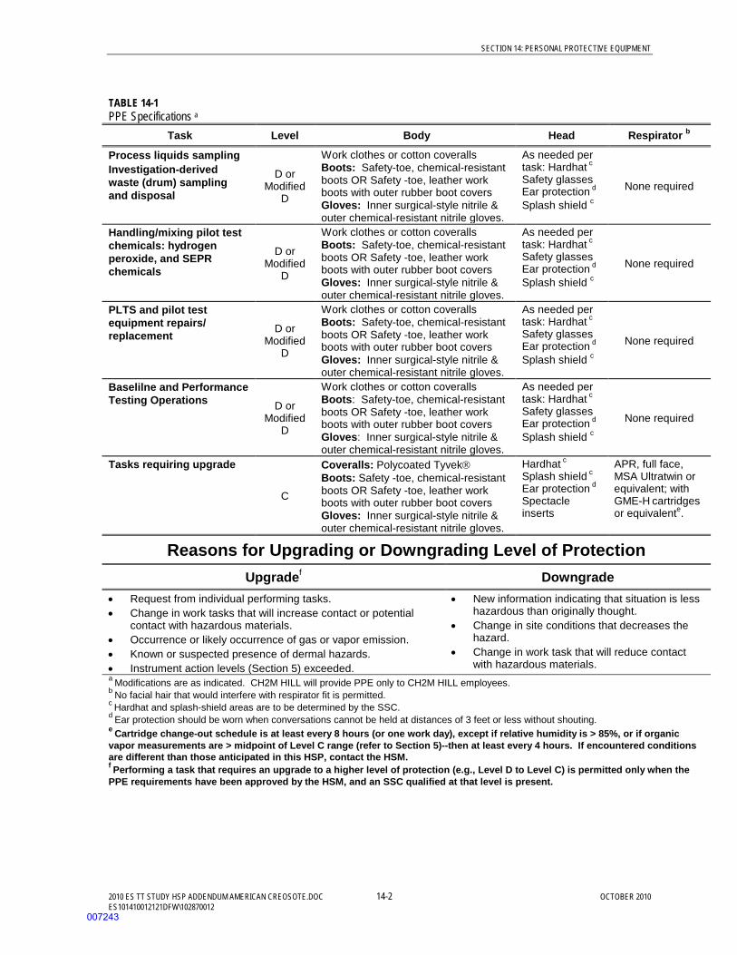
SECTION 14: PERSONAL PROTECTIVE EQUIPMENT
2010 ES TT STUDY HSP ADDENDUM AMERICAN CREOSOTE.DOC 14-2 OCTOBER 2010 ES101410012121DFW\102870012
TABLE 14-1 PPE Specifications a
Task Level Body Head Respirator b
Process liquids sampling Investigation-derived waste (drum) sampling and disposal
D or Modified
D
Work clothes or cotton coveralls Boots: Safety-toe, chemical-resistant boots OR Safety -toe, leather work boots with outer rubber boot covers Gloves: Inner surgical-style nitrile & outer chemical-resistant nitrile gloves.
As needed per task: Hardhat c Safety glasses Ear protection d
Splash shield c
None required
Handling/mixing pilot test chemicals: hydrogen peroxide, and SEPR chemicals
D or Modified
D
Work clothes or cotton coveralls Boots: Safety-toe, chemical-resistant boots OR Safety -toe, leather work boots with outer rubber boot covers Gloves: Inner surgical-style nitrile & outer chemical-resistant nitrile gloves.
As needed per task: Hardhat c Safety glasses Ear protection d
Splash shield c
None required
PLTS and pilot test equipment repairs/ replacement D or
Modified D
Work clothes or cotton coveralls Boots: Safety-toe, chemical-resistant boots OR Safety -toe, leather work boots with outer rubber boot covers Gloves: Inner surgical-style nitrile & outer chemical-resistant nitrile gloves.
As needed per task: Hardhat c Safety glasses Ear protection d
Splash shield c
None required
Baselilne and Performance Testing Operations D or
Modified D
Work clothes or cotton coveralls Boots: Safety-toe, chemical-resistant boots OR Safety -toe, leather work boots with outer rubber boot covers Gloves: Inner surgical-style nitrile & outer chemical-resistant nitrile gloves.
As needed per task: Hardhat c Safety glasses Ear protection d
Splash shield c
None required
Tasks requiring upgrade
C
Coveralls: Polycoated Tyvek Boots: Safety -toe, chemical-resistant boots OR Safety -toe, leather work boots with outer rubber boot covers Gloves: Inner surgical-style nitrile & outer chemical-resistant nitrile gloves.
Hardhat c Splash shield c Ear protection d
Spectacle inserts
APR, full face, MSA Ultratwin or equivalent; with GME-H cartridges or equivalente.
Reasons for Upgrading or Downgrading Level of Protection Upgradef Downgrade
• Request from individual performing tasks. • Change in work tasks that will increase contact or potential
contact with hazardous materials. • Occurrence or likely occurrence of gas or vapor emission. • Known or suspected presence of dermal hazards. • Instrument action levels (Section 5) exceeded.
• New information indicating that situation is less hazardous than originally thought.
• Change in site conditions that decreases the hazard.
• Change in work task that will reduce contact with hazardous materials.
a Modifications are as indicated. CH2M HILL will provide PPE only to CH2M HILL employees. b No facial hair that would interfere with respirator fit is permitted. c Hardhat and splash-shield areas are to be determined by the SSC. d Ear protection should be worn when conversations cannot be held at distances of 3 feet or less without shouting. e Cartridge change-out schedule is at least every 8 hours (or one work day), except if relative humidity is > 85%, or if organic vapor measurements are > midpoint of Level C range (refer to Section 5)--then at least every 4 hours. If encountered conditions are different than those anticipated in this HSP, contact the HSM. f Performing a task that requires an upgrade to a higher level of protection (e.g., Level D to Level C) is permitted only when the PPE requirements have been approved by the HSM, and an SSC qualified at that level is present.
007243
SECTION 14: PERSONAL PROTECTIVE EQUIPMENT
2010 ES TT STUDY HSP ADDENDUM AMERICAN CREOSOTE.DOC 14-3 OCTOBER 2010 ES101410012121DFW\102870012
14.2 Respiratory Protection (Reference CH2M HILL SOP HSE-121, Respiratory Protection)
During pilot testing, respiratory protection is required if adequate ventilation is unavailable. Implement the following when using respiratory protection:
• Respirator users must have completed appropriate respirator training within the past 12 months. Level C training is required for air-purifying respirators (APR) use and Level B training is required for supplied-air respirators (SAR) and self-contained breathing apparatus (SCBA) use. Specific training is required for the use of powered air-purifying respirators (PAPR).
• Respirator users must complete the respirator medical monitoring protocol and been approved for the specific type of respirator to be used.
• Tight-fitting facepiece respirator (negative or positive pressure) users must have passed an appropriate fit test within past 12 months.
• Respirator use shall be limited to those activities identified in this plan. If site conditions change that alters the effectiveness of the specified respiratory protection, the RHSM shall be notified to amend the written plan.
• Tight-fitting facepiece respirator users shall be clean-shaven and shall perform a user seal check before each use.
• Canisters/cartridges shall be replaced according to the change-out schedule specified in this plan. Respirator users shall notify the SC or RHSM of any detection of vapor or gas breakthrough. The SC shall report any breakthrough events to the RHSM for schedule upgrade.
• Respirators in regular use shall be inspected before each use and during cleaning
• Respirators in regular use shall be cleaned and disinfected as often as necessary to ensure they are maintained in a clean and sanitary condition.
• Respirators shall be properly stored to protect against contamination and deformation.
• Field repair of respirators shall be limited to routine maintenance. Defective respirators shall be removed from service.
• When breathing air is supplied by cylinder or compressor, the SC or RHSM shall verify the air meets Grade D air specifications.
• The SC or designee shall complete the H&S Self-Assessment Checklist – Respiratory Protection included in as attachment to this plan to verify compliance with CH2M HILL’s respiratory protection program.
007244
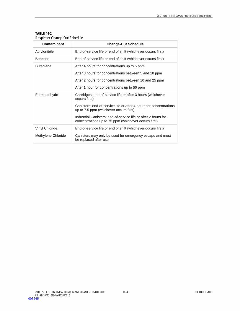
SECTION 14: PERSONAL PROTECTIVE EQUIPMENT
2010 ES TT STUDY HSP ADDENDUM AMERICAN CREOSOTE.DOC 14-4 OCTOBER 2010 ES101410012121DFW\102870012
TABLE 14-2 Respirator Change-Out Schedule
Contaminant Change-Out Schedule
Acrylonitrile End-of-service life or end of shift (whichever occurs first)
Benzene End-of-service life or end of shift (whichever occurs first)
Butadiene After 4 hours for concentrations up to 5 ppm
After 3 hours for concentrations between 5 and 10 ppm
After 2 hours for concentrations between 10 and 25 ppm
After 1 hour for concentrations up to 50 ppm
Formaldehyde Cartridges: end-of-service life or after 3 hours (whichever occurs first)
Canisters: end-of-service life or after 4 hours for concentrations up to 7.5 ppm (whichever occurs first)
Industrial Canisters: end-of-service life or after 2 hours for concentrations up to 75 ppm (whichever occurs first)
Vinyl Chloride End-of-service life or end of shift (whichever occurs first)
Methylene Chloride Canisters may only be used for emergency escape and must be replaced after use
007245

2010 ES TT STUDY HSP ADDENDUM AMERICAN CREOSOTE.DOC 15-1 OCTOBER 2010 ES101410012121DFW\102870012
SECTION 15
Worker Training and Qualification
See the HSP American Creosote Works (CH2M HILL, 2010).
007246

SECTION 15: WORKER TRAINING AND QUALIFICATION
2010 ES TT STUDY HSP ADDENDUM AMERICAN CREOSOTE.DOC 15-2 OCTOBER 2010 ES101410012121DFW\102870012
(This page intentionally left blank)
007247

2010 ES TT STUDY HSP ADDENDUM AMERICAN CREOSOTE.DOC 16-1 OCTOBER 2010 ES101410012121DFW\102870012
SECTION 16
Medical Surveillance and Qualification
See the HSP American Creosote Works (CH2M HILL, 2010).
007248

SECTION 16: MEDICAL SURVEILLANCE AND QUALIFICATION
2010 ES TT STUDY HSP ADDENDUM AMERICAN CREOSOTE.DOC 16-2 OCTOBER 2010 ES101410012121DFW\102870012
(This page intentionally left blank)
007249

2010 ES TT STUDY HSP ADDENDUM AMERICAN CREOSOTE.DOC 17-1 OCTOBER 2010 ES101410012121DFW\102870012
SECTION 17
Site-Control Plan
See the HSP American Creosote Works (CH2M HILL, 2010).
007250

SECTION 17: SITE-CONTROL PLAN
2010 ES TT STUDY HSP ADDENDUM AMERICAN CREOSOTE.DOC 17-2 OCTOBER 2010 ES101410012121DFW\102870012
(This page intentionally left blank)
007251
2010 ES TT STUDY HSP ADDENDUM AMERICAN CREOSOTE.DOC 18-1 OCTOBER 2010 ES101410012121DFW\102870012
SECTION 18
Decontamination
See the HSP American Creosote Works (CH2M HILL, 2010).
007252

SECTION 18: SECTION 18 17BDECONTAMINATION
2010 ES TT STUDY HSP ADDENDUM AMERICAN CREOSOTE.DOC 18-2 OCTOBER 2010 ES101410012121DFW\102870012
(This page intentionally left blank)
007253

2010 ES TT STUDY HSP ADDENDUM AMERICAN CREOSOTE.DOC 19-1 OCTOBER 2010 ES101410012121DFW\102870012
SECTION 19
Emergency Response Plan
See the HSP American Creosote Works (CH2M HILL, 2010).
(Reference CH2M HILL SOP HSE-106, Emergency Planning)
19.1 Pre-Emergency Planning • The Emergency Response Coordinator (ERC), typically the SC or designee, performs the
applicable pre-emergency planning tasks before starting field activities and coordinates emergency response with CH2M HILL onsite parties, the facility, and local emergency-service providers as appropriate. Pre-Emergency Planning activities performed by the ERC include:
• Review the facility emergency and contingency plans where applicable.
• Determine what onsite communication equipment is available (e.g., two-way radio, air horn).
• Determine what offsite communication equipment is needed (e.g., nearest telephone, cell phone).
• Confirm and post the “Emergency Contacts” page and route to the hospital located in this section in project trailer(s) and keep a copy in field vehicles along with evacuation routes and assembly areas. Communicate the information to onsite personnel and keep it updated.
• Field Trailers: Post “Exit” signs above exit doors, and post “Fire Extinguisher” signs above locations of extinguishers. Keep areas near exits and extinguishers clear.
• Review changed site conditions, onsite operations, and personnel availability in relation to emergency response procedures.
• Where appropriate and acceptable to the client, inform emergency room and ambulance and emergency response teams of anticipated types of site emergencies.
• Designate one vehicle as the emergency vehicle; place hospital directions and map inside; keep keys in ignition during field activities.
• Inventory and check site emergency equipment, supplies, and potable water.
• Communicate emergency procedures for personnel injury, exposures, fires, explosions, and releases.
• Rehearse the emergency response plan before site activities begin, including driving route to hospital. Drills should take place periodically but no less than once a year.
• Brief new workers on the emergency response plan.
007254
SECTION 19: SECTION 18 17BDECONTAMINATION
2010 ES TT STUDY HSP ADDENDUM AMERICAN CREOSOTE.DOC 19-2 OCTOBER 2010 ES101410012121DFW\102870012
• The ERC will evaluate emergency response actions and initiate appropriate follow-up actions.
19.2 Emergency Equipment and Supplies The ERC should mark the locations of emergency equipment on the site map and post the map.
Emergency Equipment and Supplies Location
• 20 (or two 10) class A,B,C fire extinguisher PLTS Building • First aid kit • Eye Wash • Emergency Shower • Potable water • Bloodborne-pathogen kit • Additional equipment (specify):
19.3 Incident Response In fires, explosions, or chemical releases, actions to be taken include the following:
• Notify appropriate response personnel. • Shut down CH2M HILL operations and evacuate the immediate work area. • Account for personnel at the designated assembly area(s). • Assess the need for site evacuation, and evacuate the site as warranted. • Implement HSE-111, Incident Notification, Reporting and Investigation. • Notify and submit reports to clients as required in contract.
Small fires or spills posing minimal safety or health hazards may be controlled with onsite spill kits or fire extinguishers without evacuating the site. When in doubt evacuate. Follow the incident reporting procedures in the “Incident Notification, Reporting, and Investigation” section of this HSP.
19.4 Emergency Medical Treatment Emergency medical treatment is needed when there is a life-threatening injury (such as severe bleeding, loss of consciousness, breathing/heart has stopped). When in doubt if an injury is life-threatening or not, treat it as needing emergency medical treatment.
• Notify 911 or other appropriate emergency response authorities as listed in the “Emergency Contacts” page located in this section.
• The ERC will assume charge during a medical emergency until the ambulance arrives or until the injured person is admitted to the emergency room.
• Prevent further injury, perform decontamination (if applicable) where feasible; lifesaving and first aid or medical treatment takes priority.
007255
SECTION 19: SECTION 18 17BDECONTAMINATION
2010 ES TT STUDY HSP ADDENDUM AMERICAN CREOSOTE.DOC 19-3 OCTOBER 2010 ES101410012121DFW\102870012
• Initiate first aid and CPR where feasible.
• Notify supervisor and if the injured person is a CH2M HILL employee, the supervisor will call the occupational nurse at 1-866-893-2514 and make other notifications as required by HSE SOP-111, Incident Notification, Reporting and Investigation.
• Make certain that the injured person is accompanied to the emergency room.
• Follow the Serious Incident Reporting process in HSE SOP-111, Incident Notification, Reporting and Investigation, and complete incident report using the HITS system on the Virtual Office or if not feasible, use the hard copy forms provided as an attachment to this HSP.
• Notify and submit reports to client as required in contract.
19.5 Evacuation • Evacuation routes, assembly areas, and severe weather shelters (and alternative routes
and assembly areas) are to be specified on the site map.
• Evacuation route(s) and assembly area(s) will be designated by the ERC or designee before work begins.
• Personnel will assemble at the assembly area(s) upon hearing the emergency signal for evacuation.
• The ERC and a “buddy” will remain on the site after the site has been evacuated (if safe) to assist local responders and advise them of the nature and location of the incident.
• The ERC will account for all personnel in the onsite assembly area.
• A designated person will account for personnel at alternate assembly area(s).
• The ERC will follow the incident reporting procedures in the “Incident Notification, Reporting and Investigation” section of this HSP.
19.6 Evacuation Signals Signal Meaning
• Grasping throat with hand • Emergency-help me. Thumbs up • OK; understood.
• Grasping buddy’s wrist • Leave area now. • Continuous sounding of horn • Emergency; leave site now.
19.7 Inclement Weather See the HSP American Creosote Works (CH2M HILL, 2010).
007256
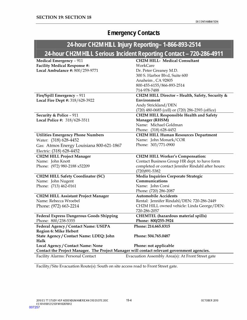
SECTION 19: SECTION 18 17BDECONTAMINATION
2010 ES TT STUDY HSP ADDENDUM AMERICAN CREOSOTE.DOC 19-4 OCTOBER 2010 ES101410012121DFW\102870012
Emergency Contacts
24-hour CH2M HILL Injury Reporting– 1-866-893-2514 24-hour CH2M HILL Serious Incident Reporting Contact – 720-286-4911
Medical Emergency – 911 Facility Medical Response #: Local Ambulance #: 800/259-9771
CH2M HILL- Medical Consultant WorkCare Dr. Peter Greaney M.D. 300 S. Harbor Blvd, Suite 600 Anaheim , CA 92805 800-455-6155/866-893-2514 714-978-7488
Fire/Spill Emergency – 911 Local Fire Dept #: 318/628-3922
CH2M HILL Director – Health, Safety, Security & Environment Andy Strickland/DEN (720) 480-0685 (cell) or (720) 286-2393 (office)
Security & Police – 911 Local Police #: 318/628-3511
CH2M HILL Responsible Health and Safety Manager (RHSM) Name: Michael Goldman Phone: (318) 628-4452
Utilities Emergency Phone Numbers Water: (318) 628-4452 Gas: Atmos Energy Louisiana 800-621-1867 Electric: (318) 628-4452
CH2M HILL Human Resources Department Name: John Monark/COR Phone: 303/771-0900
CH2M HILL Project Manager Name: John Knott Phone: (972) 980-2188 x52209
CH2M HILL Worker’s Compensation: Contact Business Group HR dept. to have form completed or contact Jennifer Rindahl after hours: (720)891-5382
CH2M HILL Safety Coordinator (SC) Name: John Nugent Phone: (713) 462-0161
Media Inquiries Corporate Strategic Communications Name: John Corsi Phone: (720) 286-2087
CH2M HILL Assistant Project Manager Name: Rebecca Wroebel Phone: (972) 663-2214
Automobile Accidents Rental: Jennifer Rindahl/DEN: 720-286-2449 CH2M HILL owned vehicle: Linda George/DEN: 720-286-2057
Federal Express Dangerous Goods Shipping Phone: 800/238-5355
CHEMTEL (hazardous material spills) Phone: 800/255-3924
Federal Agency / Contact Name: USEPA Region 6: Mike Hebert State Agency / Contact Name: LDEQ: John Halk Local Agency / Contact Name: None
Phone: 214.665.8315 Phone: 504.765.0487 Phone: not applicable
Contact the Project Manager. The Project Manager will contact relevant government agencies. Facility Alarms: Personal Contact
Evacuation Assembly Area(s): At Front Street gate
Facility/Site Evacuation Route(s): South on site access road to Front Street gate.
007257

SECTION 19: SECTION 18 17BDECONTAMINATION
2010 ES TT STUDY HSP ADDENDUM AMERICAN CREOSOTE.DOC 19-5 OCTOBER 2010 ES101410012121DFW\102870012
Directions to Local Hospital Driving Directions: From main gate turn North (right) and go north on Front street (SR-1231) for 0.3 miles; Veer left at the “Y” onto Beville street and go .4 miles to Lafayette street; Turn left onto Lafayette street and follow it until it dead ends into the Hospital emergency drive.
007258

SECTION 19: SECTION 18 17BDECONTAMINATION
2010 ES TT STUDY HSP ADDENDUM AMERICAN CREOSOTE.DOC 19-6 OCTOBER 2010 ES101410012121DFW\102870012
(This page intentionally left blank)
007259
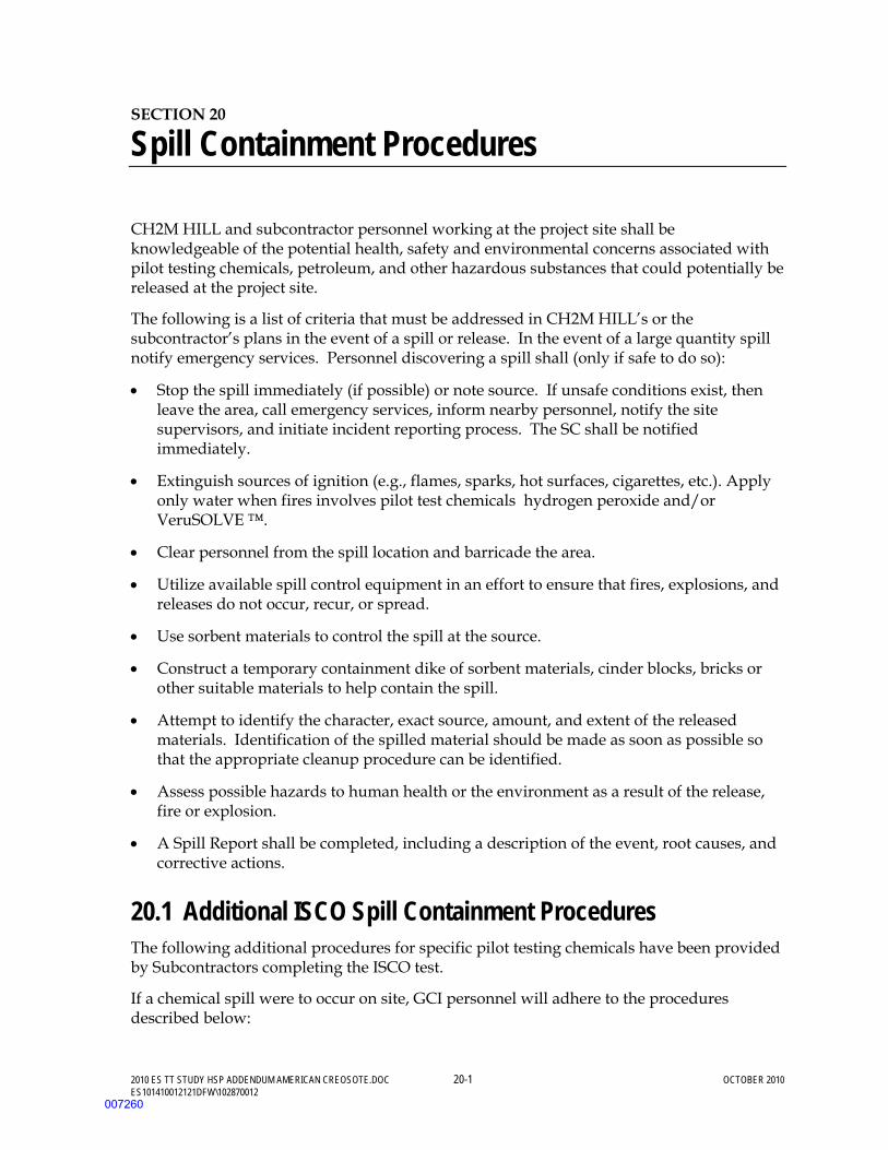
2010 ES TT STUDY HSP ADDENDUM AMERICAN CREOSOTE.DOC 20-1 OCTOBER 2010 ES101410012121DFW\102870012
SECTION 20
Spill Containment Procedures
CH2M HILL and subcontractor personnel working at the project site shall be knowledgeable of the potential health, safety and environmental concerns associated with pilot testing chemicals, petroleum, and other hazardous substances that could potentially be released at the project site.
The following is a list of criteria that must be addressed in CH2M HILL’s or the subcontractor’s plans in the event of a spill or release. In the event of a large quantity spill notify emergency services. Personnel discovering a spill shall (only if safe to do so):
• Stop the spill immediately (if possible) or note source. If unsafe conditions exist, then leave the area, call emergency services, inform nearby personnel, notify the site supervisors, and initiate incident reporting process. The SC shall be notified immediately.
• Extinguish sources of ignition (e.g., flames, sparks, hot surfaces, cigarettes, etc.). Apply only water when fires involves pilot test chemicals hydrogen peroxide and/or VeruSOLVE ™.
• Clear personnel from the spill location and barricade the area.
• Utilize available spill control equipment in an effort to ensure that fires, explosions, and releases do not occur, recur, or spread.
• Use sorbent materials to control the spill at the source.
• Construct a temporary containment dike of sorbent materials, cinder blocks, bricks or other suitable materials to help contain the spill.
• Attempt to identify the character, exact source, amount, and extent of the released materials. Identification of the spilled material should be made as soon as possible so that the appropriate cleanup procedure can be identified.
• Assess possible hazards to human health or the environment as a result of the release, fire or explosion.
• A Spill Report shall be completed, including a description of the event, root causes, and corrective actions.
20.1 Additional ISCO Spill Containment Procedures The following additional procedures for specific pilot testing chemicals have been provided by Subcontractors completing the ISCO test.
If a chemical spill were to occur on site, GCI personnel will adhere to the procedures described below:
007260
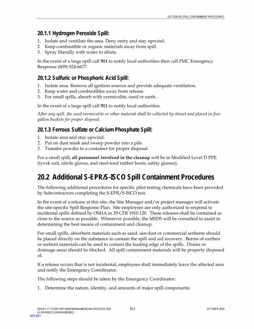
SECTION 20: SPILL CONTAINMENT PROCEDURES
2010 ES TT STUDY HSP ADDENDUM AMERICAN CREOSOTE.DOC 20-2 OCTOBER 2010 ES101410012121DFW\102870012
20.1.1 Hydrogen Peroxide Spill: 1. Isolate and ventilate the area. Deny entry and stay upwind. 2. Keep combustible or organic materials away from spill. 3. Spray liberally with water to dilute.
In the event of a large spill call 911 to notify local authorities then call FMC Emergency Response (609) 924-6677.
20.1.2 Sulfuric or Phosphoric Acid Spill: 1. Isolate area. Remove all ignition sources and provide adequate ventilation. 2. Keep water and combustibles away from release. 3. For small spills, absorb with vermiculite, sand or earth.
In the event of a large spill call 911 to notify local authorities.
After any spill, the used vermiculite or other material shall be collected by shovel and placed in five-gallon buckets for proper disposal.
20.1.3 Ferrous Sulfate or Calcium Phosphate Spill: 1. Isolate area and stay upwind. 2. Put on dust mask and sweep powder into a pile. 3. Transfer powder to a container for proper disposal.
For a small spill, all personnel involved in the cleanup will be in Modified Level D PPE (tyvek suit, nitrile gloves, and steel-toed rubber boots, safety glasses).
20.2 Additional S-EPR/S-ISCO Spill Containment Procedures The following additional procedures for specific pilot testing chemicals have been provided by Subcontractors completing the S-EPR/S-ISCO test.
In the event of a release at this site, the Site Manager and/or project manager will activate the site-specific Spill Response Plan. Site employees are only authorized to respond to incidental spills defined by OSHA in 29 CFR 1910.120. These releases shall be contained as close to the source as possible. Whenever possible, the MSDS will be consulted to assist in determining the best means of containment and cleanup.
For small spills, absorbent materials such as sand, sawdust or commercial sorbents should be placed directly on the substance to contain the spill and aid recovery. Berms of earthen or sorbent materials can be used to contain the leading edge of the spills. Drains or drainage areas should be blocked. All spill containment materials will be properly disposed of.
If a release occurs that is not incidental, employees shall immediately leave the affected area and notify the Emergency Coordinator.
The following steps should be taken by the Emergency Coordinator:
1. Determine the nature, identity, and amounts of major spill components;
007261
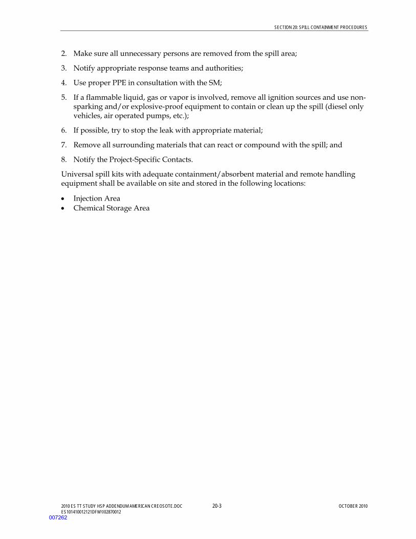
SECTION 20: SPILL CONTAINMENT PROCEDURES
2010 ES TT STUDY HSP ADDENDUM AMERICAN CREOSOTE.DOC 20-3 OCTOBER 2010 ES101410012121DFW\102870012
2. Make sure all unnecessary persons are removed from the spill area;
3. Notify appropriate response teams and authorities;
4. Use proper PPE in consultation with the SM;
5. If a flammable liquid, gas or vapor is involved, remove all ignition sources and use non-sparking and/or explosive-proof equipment to contain or clean up the spill (diesel only vehicles, air operated pumps, etc.);
6. If possible, try to stop the leak with appropriate material;
7. Remove all surrounding materials that can react or compound with the spill; and
8. Notify the Project-Specific Contacts.
Universal spill kits with adequate containment/absorbent material and remote handling equipment shall be available on site and stored in the following locations:
• Injection Area • Chemical Storage Area
007262

SECTION 20: SPILL CONTAINMENT PROCEDURES
2010 ES TT STUDY HSP ADDENDUM AMERICAN CREOSOTE.DOC 20-4 OCTOBER 2010 ES101410012121DFW\102870012
(This page intentionally left blank)
007263
2010 ES TT STUDY HSP ADDENDUM AMERICAN CREOSOTE.DOC 21-1 OCTOBER 2010 ES101410012121DFW\102870012
SECTION 21
Inspections
21.1 Project Activity Self-Assessment Checklists See the HSP American Creosote Works (CH2M HILL, 2010).
21.2 Safe Behavior Observations See the HSP American Creosote Works (CH2M HILL, 2010).
007264

SECTION 21: INSPECTIONS
2010 ES TT STUDY HSP ADDENDUM AMERICAN CREOSOTE.DOC 21-2 OCTOBER 2010 ES101410012121DFW\102870012
(This page intentionally left blank)
007265

2010 ES TT STUDY HSP ADDENDUM AMERICAN CREOSOTE.DOC 22-1 OCTOBER 2010 ES101410012121DFW\102870012
SECTION 22
Incident Notification, Reporting, and Investigation
(Reference CH2M HILL SOP HSE-111, Incident Notification, Reporting and Investigation)
See the HSP American Creosote Works (CH2M HILL, 2010).
007266

SECTION 22: INCIDENT NOTIFICATION, REPORTING, AND INVESTIGATION
2010 ES TT STUDY HSP ADDENDUM AMERICAN CREOSOTE.DOC 22-2 OCTOBER 2010 ES101410012121DFW\102870012
(This page intentionally left blank)
007267

2010 ES TT STUDY HSP ADDENDUM AMERICAN CREOSOTE.DOC 23-1 OCTOBER 2010 ES101410012121DFW\102870012
SECTION 23
Records and Reports
See the HSP American Creosote Works (CH2M HILL, 2010).
007268

SECTION 23:RECORDS AND REPORTS
2010 ES TT STUDY HSP ADDENDUM AMERICAN CREOSOTE.DOC 23-2 OCTOBER 2010 ES101410012121DFW\102870012
(This page intentionally left blank)
007269

Attachments
007270

ATTACHMENTS
2010 ES TT STUDY HSP ADDENDUM AMERICAN CREOSOTE.DOC OCTOBER 2010 ES101410012121DFW\102870012
(This page intentionally left blank)
007271

2010 ES TT STUDY HSP ADDENDUM AMERICAN CREOSOTE.DOC A-1 OCTOBER 2010 ES101410012121DFW\102870012
ATTACHMENT 1
Health and Safety Plan Employee Sign-off Form
EMPLOYEE SIGNOFF FORM Health and Safety Plan
The CH2M HILL project employees and subcontractors listed below have been provided with a copy of this HSP, have read and understood it, and agree to abide by its provisions.
Project Name: Project Number:
EMPLOYEE NAME (Please print) EMPLOYEE SIGNATURE COMPANY DATE
007272

2010 ES TT STUDY HSP ADDENDUM AMERICAN CREOSOTE.DOC A-2 OCTOBER 2010 ES101410012121DFW\102870012
ATTACHMENT 2
Chemical Inventory/Register Form
CHEMICAL INVENTORY/REGISTER FORM
Refer to SOP HSE-107, Attachment 1, for instructions on completing this form.
Location: American Creosote Works, Winn Parish, Winnfield, Louisiana
HCC:
Office Warehouse Laboratory Project:
Project No.: 344582
Regulated Product Location Container labeled (if yes)
MSDS available (if yes)
Hydrogen Peroxide (34% solution) Process area/chemical storage
SEPR solution Process area/chemical storage VeruSOL® Process area/chemical storage VeruSOLVE-HP®) Process area/chemical storage GreenCat™ Process area/chemical storage Stabilization Chemicals Lab
MSDS for the listed products will be maintained at:
007273
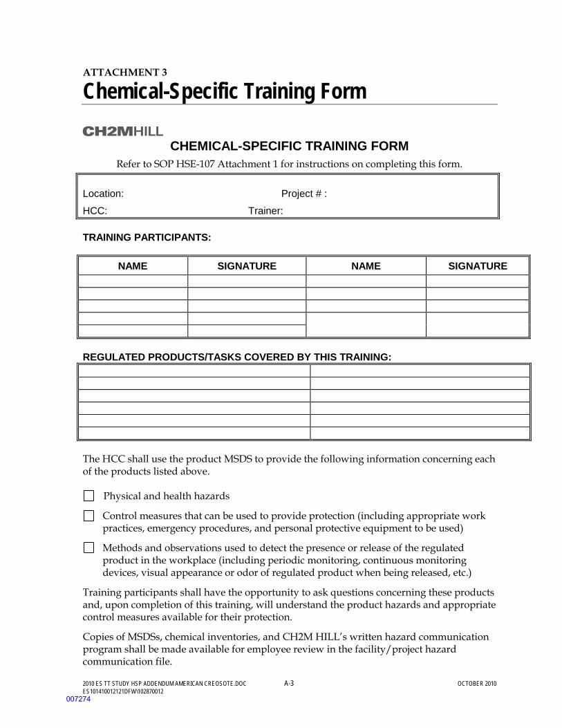
2010 ES TT STUDY HSP ADDENDUM AMERICAN CREOSOTE.DOC A-3 OCTOBER 2010 ES101410012121DFW\102870012
ATTACHMENT 3
Chemical-Specific Training Form
CHEMICAL-SPECIFIC TRAINING FORM
Refer to SOP HSE-107 Attachment 1 for instructions on completing this form. Location: Project # :
HCC: Trainer: TRAINING PARTICIPANTS:
NAME SIGNATURE NAME SIGNATURE REGULATED PRODUCTS/TASKS COVERED BY THIS TRAINING: The HCC shall use the product MSDS to provide the following information concerning each of the products listed above.
Physical and health hazards
Control measures that can be used to provide protection (including appropriate work practices, emergency procedures, and personal protective equipment to be used)
Methods and observations used to detect the presence or release of the regulated product in the workplace (including periodic monitoring, continuous monitoring devices, visual appearance or odor of regulated product when being released, etc.)
Training participants shall have the opportunity to ask questions concerning these products and, upon completion of this training, will understand the product hazards and appropriate control measures available for their protection.
Copies of MSDSs, chemical inventories, and CH2M HILL’s written hazard communication program shall be made available for employee review in the facility/project hazard communication file.
007274

2010 ES TT STUDY HSP ADDENDUM AMERICAN CREOSOTE.DOC A-4 OCTOBER 2010
ES101410012121DFW\102870012
ATTACHMENT 4
Project Activity Self-Assessment Checklists/Permits/Forms
The Project Activity Self-Assessment checklists, permits and forms will be provided with the final submission of the Work Plan.
007275
2010 ES TT STUDY HSP ADDENDUM AMERICAN CREOSOTE.DOC A-5 OCTOBER 2010 ES101410012121DFW\102870012
ATTACHMENT 5
Behavior Based Loss Prevention System Forms
See the HSP American Creosote Works (CH2M HILL, 2010).
Activity Hazard Analysis Pre-Task Safety Plans
Safe Behavior Observation Incident Report and Investigation
(use electronic form when possible) HITS
007276

2010 ES TT STUDY HSP ADDENDUM AMERICAN CREOSOTE.DOC A-6 OCTOBER 2010 ES101410012121DFW\102870012
ATTACHMENT 6
Material Safety Data Sheets
See the HSP American Creosote Works (CH2M HILL, 2010).
007277

ATTACHMENTS
2010 ES TT STUDY HSP ADDENDUM AMERICAN CREOSOTE.DOC OCTOBER 2010 ES101410012121DFW\102870012
(This page intentionally left blank)
007278
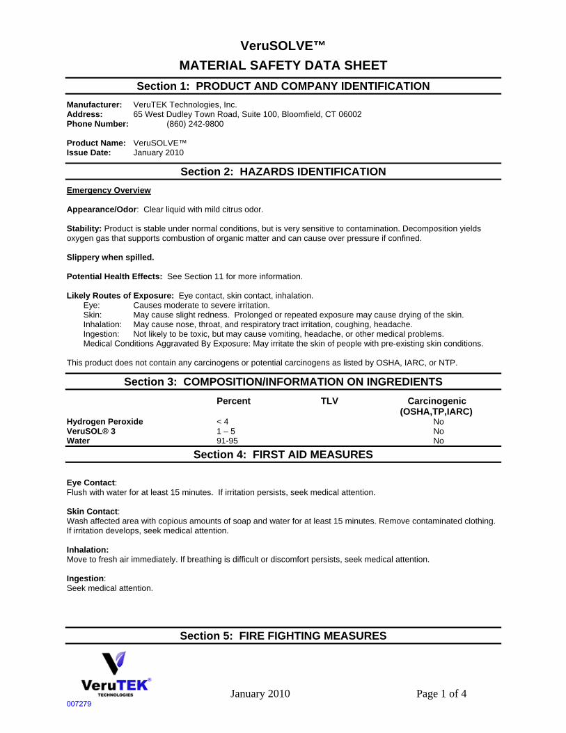
January 2010 Page 1 of 4
VeruSOLVE™ MATERIAL SAFETY DATA SHEET
Section 1: PRODUCT AND COMPANY IDENTIFICATION
Manufacturer: VeruTEK Technologies, Inc. Address: 65 West Dudley Town Road, Suite 100, Bloomfield, CT 06002 Phone Number: (860) 242-9800 Product Name: VeruSOLVE™ Issue Date: January 2010
Section 2: HAZARDS IDENTIFICATION
Emergency Overview Appearance/Odor: Clear liquid with mild citrus odor. Stability: Product is stable under normal conditions, but is very sensitive to contamination. Decomposition yields oxygen gas that supports combustion of organic matter and can cause over pressure if confined. Slippery when spilled. Potential Health Effects: See Section 11 for more information. Likely Routes of Exposure: Eye contact, skin contact, inhalation. Eye: Causes moderate to severe irritation. Skin: May cause slight redness. Prolonged or repeated exposure may cause drying of the skin. Inhalation: May cause nose, throat, and respiratory tract irritation, coughing, headache. Ingestion: Not likely to be toxic, but may cause vomiting, headache, or other medical problems. Medical Conditions Aggravated By Exposure: May irritate the skin of people with pre-existing skin conditions. This product does not contain any carcinogens or potential carcinogens as listed by OSHA, IARC, or NTP.
Section 3: COMPOSITION/INFORMATION ON INGREDIENTS
Percent TLV Carcinogenic (OSHA,TP,IARC) Hydrogen Peroxide < 4 No VeruSOL® 3 1 – 5 No Water 91-95 No
Section 4: FIRST AID MEASURES
Eye Contact: Flush with water for at least 15 minutes. If irritation persists, seek medical attention. Skin Contact: Wash affected area with copious amounts of soap and water for at least 15 minutes. Remove contaminated clothing. If irritation develops, seek medical attention. Inhalation: Move to fresh air immediately. If breathing is difficult or discomfort persists, seek medical attention. Ingestion: Seek medical attention.
Section 5: FIRE FIGHTING MEASURES
007279
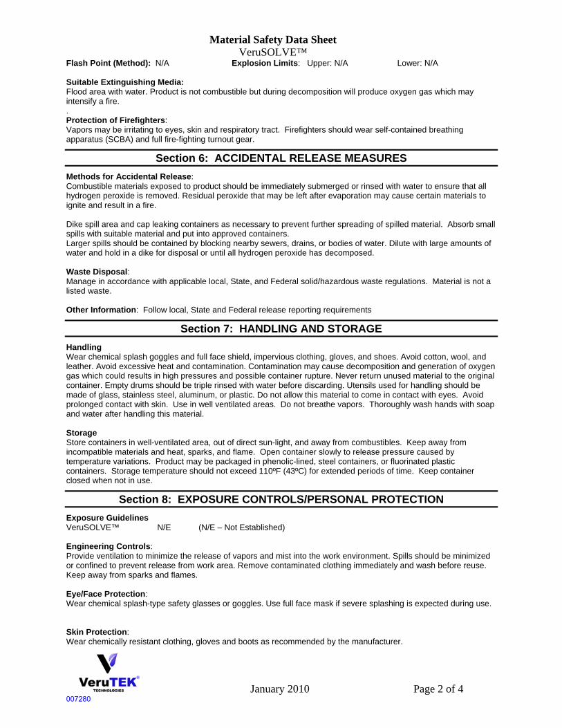
Material Safety Data Sheet VeruSOLVE™
January 2010 Page 2 of 4
Flash Point (Method): N/A Explosion Limits: Upper: N/A Lower: N/A Suitable Extinguishing Media: Flood area with water. Product is not combustible but during decomposition will produce oxygen gas which may intensify a fire. . Protection of Firefighters: Vapors may be irritating to eyes, skin and respiratory tract. Firefighters should wear self-contained breathing apparatus (SCBA) and full fire-fighting turnout gear.
Section 6: ACCIDENTAL RELEASE MEASURES
Methods for Accidental Release: Combustible materials exposed to product should be immediately submerged or rinsed with water to ensure that all hydrogen peroxide is removed. Residual peroxide that may be left after evaporation may cause certain materials to ignite and result in a fire. Dike spill area and cap leaking containers as necessary to prevent further spreading of spilled material. Absorb small spills with suitable material and put into approved containers. Larger spills should be contained by blocking nearby sewers, drains, or bodies of water. Dilute with large amounts of water and hold in a dike for disposal or until all hydrogen peroxide has decomposed. Waste Disposal: Manage in accordance with applicable local, State, and Federal solid/hazardous waste regulations. Material is not a listed waste. Other Information: Follow local, State and Federal release reporting requirements
Section 7: HANDLING AND STORAGE
Handling Wear chemical splash goggles and full face shield, impervious clothing, gloves, and shoes. Avoid cotton, wool, and leather. Avoid excessive heat and contamination. Contamination may cause decomposition and generation of oxygen gas which could results in high pressures and possible container rupture. Never return unused material to the original container. Empty drums should be triple rinsed with water before discarding. Utensils used for handling should be made of glass, stainless steel, aluminum, or plastic. Do not allow this material to come in contact with eyes. Avoid prolonged contact with skin. Use in well ventilated areas. Do not breathe vapors. Thoroughly wash hands with soap and water after handling this material. Storage Store containers in well-ventilated area, out of direct sun-light, and away from combustibles. Keep away from incompatible materials and heat, sparks, and flame. Open container slowly to release pressure caused by temperature variations. Product may be packaged in phenolic-lined, steel containers, or fluorinated plastic containers. Storage temperature should not exceed 110ºF (43ºC) for extended periods of time. Keep container closed when not in use.
Section 8: EXPOSURE CONTROLS/PERSONAL PROTECTION
Exposure Guidelines VeruSOLVE™ N/E (N/E – Not Established) Engineering Controls: Provide ventilation to minimize the release of vapors and mist into the work environment. Spills should be minimized or confined to prevent release from work area. Remove contaminated clothing immediately and wash before reuse. Keep away from sparks and flames. Eye/Face Protection: Wear chemical splash-type safety glasses or goggles. Use full face mask if severe splashing is expected during use. Skin Protection: Wear chemically resistant clothing, gloves and boots as recommended by the manufacturer.
007280
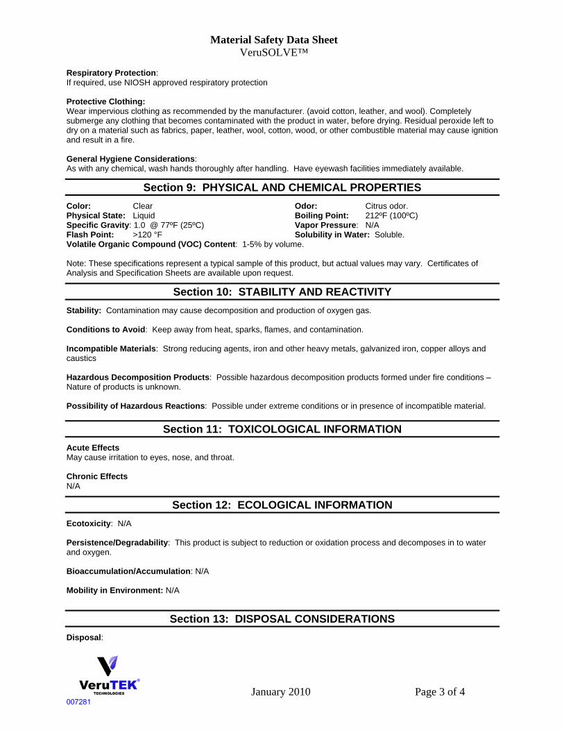
Material Safety Data Sheet VeruSOLVE™
January 2010 Page 3 of 4
Respiratory Protection: If required, use NIOSH approved respiratory protection Protective Clothing: Wear impervious clothing as recommended by the manufacturer. (avoid cotton, leather, and wool). Completely submerge any clothing that becomes contaminated with the product in water, before drying. Residual peroxide left to dry on a material such as fabrics, paper, leather, wool, cotton, wood, or other combustible material may cause ignition and result in a fire. General Hygiene Considerations: As with any chemical, wash hands thoroughly after handling. Have eyewash facilities immediately available.
Section 9: PHYSICAL AND CHEMICAL PROPERTIES
Color: Clear Odor: Citrus odor. Physical State: Liquid Boiling Point: 212ºF (100ºC) Specific Gravity: 1.0 @ 77ºF (25ºC) Vapor Pressure: N/A Flash Point: >120 °F Solubility in Water: Soluble. Volatile Organic Compound (VOC) Content: 1-5% by volume. Note: These specifications represent a typical sample of this product, but actual values may vary. Certificates of Analysis and Specification Sheets are available upon request.
Section 10: STABILITY AND REACTIVITY
Stability: Contamination may cause decomposition and production of oxygen gas. Conditions to Avoid: Keep away from heat, sparks, flames, and contamination. Incompatible Materials: Strong reducing agents, iron and other heavy metals, galvanized iron, copper alloys and caustics Hazardous Decomposition Products: Possible hazardous decomposition products formed under fire conditions – Nature of products is unknown. Possibility of Hazardous Reactions: Possible under extreme conditions or in presence of incompatible material.
Section 11: TOXICOLOGICAL INFORMATION
Acute Effects May cause irritation to eyes, nose, and throat. Chronic Effects N/A
Section 12: ECOLOGICAL INFORMATION
Ecotoxicity: N/A Persistence/Degradability: This product is subject to reduction or oxidation process and decomposes in to water and oxygen. Bioaccumulation/Accumulation: N/A Mobility in Environment: N/A
Section 13: DISPOSAL CONSIDERATIONS
Disposal:
007281

Material Safety Data Sheet VeruSOLVE™
January 2010 Page 4 of 4
Dispose of in accordance with applicable local , State, and Federal regulations. Material is not a listed hazardous waste.
Section 14: TRANSPORT INFORMATION
US DOT Shipping Classification Hazard Class: Not regulated Identification No.: Not applicable Packing Group: Not applicable Label/Placard: Not applicable
TDG Status: Not regulated IMO Status: Not regulated IATA Status: Not regulated
Section 15: REGULATORY INFORMATION
Global Inventories The components of this product are included in the following inventories: USA (TSCA) Canada (DSL) Australia (AICS) Korea (KECL) Philippines (PICCS) Proposition 65: California Safe Drinking Water and Toxic Enforcement Act of 1986 This product is not known to contain any chemicals currently listed as carcinogens or reproductive toxins under California Proposition 65 at levels which would be subject to the proposition.
Section 16: OTHER INFORMATION
NFPA 704: National Fire Protection Association Health – 0 (minimal hazard) Fire – 0 (minimal hazard) Reactivity – 0 (minimal hazard)
Legend OSHA – United States Occupational Health and Safety Administration IARC – International Agency for Research on Cancer NTP – National Toxicology Program NIOSH – National Institute for Occupational Safety and Health EPA – United States Environmental Protection Agency Caution: The user should conduct his/her own experiments and establish proper procedures and
control before attempting use on critical parts.
The information contained herein is based on current knowledge and experience: no responsibility is accepted that the information is sufficient or correct in all cases. Users should consider these data only as a supplement to other information obtained by the user. No warranty is expressed or implied regarding the accuracy of this data, the results to be obtained from the use thereof, or that any such use will not infringe any patent. Users should make independent determinations of suitability and completeness of information from all sources to assure proper use and disposal of these materials, the safety and health of employees and customers, and the protection of the environment. This information is furnished upon the condition the person receiving it shall determine the suitability for the particular purpose. This MSDS is to be used as a guideline for safe work practices and emergency response.
007282

June 2006 Page 1 of 4
VeruSOL MATERIAL SAFETY DATA SHEET
Section 1: PRODUCT AND COMPANY IDENTIFICATION
Manufacturer: VeruTEK Technologies, Inc. Address: 628-2 Hebron Avenue, Suite 505, Glastonbury, CT 06033 Phone Number: (860) 633-4900 Product Name: VeruSOL Issue Date: June 2006
Section 2: HAZARDS IDENTIFICATION
Emergency Overview Appearance/Odor: Light yellow, slightly viscous liquid with citrus odor. Product is Combustible. Slippery when spilled. Potential Health Effects: See Section 11 for more information. Likely Routes of Exposure: Eye contact, skin contact, inhalation. Eye: Causes moderate to severe irritation. Skin: May cause slight redness. Prolonged or repeated exposure may cause drying of the skin. Inhalation: May cause nose, throat, and respiratory tract irritation, coughing, headache. Ingestion: Not likely to be toxic, but may cause vomiting, headache, or other medical problems. Medical Conditions Aggravated By Exposure: May irritate the skin of people with pre-existing skin
conditions. This product does not contain any carcinogens or potential carcinogens as listed by OSHA, IARC, or NTP. OSHA Regulatory Status This material is combustible, which is defined as having a flash point between 100ºF (37.8ºC) and 200ºF (93.3ºC). Combustible materials are hazardous according to the OSHA Hazard Communication Standard (29 CFR 1910.1200).
Section 3: COMPOSITION/INFORMATION ON INGREDIENTS
The specific chemical identity is being withheld as a trade secret.
Section 4: FIRST AID MEASURES
Eye Contact: Remove contact lenses at once. Flush with water for at least 15 minutes. If irritation persists, seek medical attention.
Skin Contact: Wash affected area with copious amounts of soap and water. If irritation develops, seek medical attention.
Inhalation: Move to fresh air. If symptoms persist, seek medical attention. Ingestion: Seek medical attention immediately. DO NOT induce vomiting. Rinse mouth with water. Offer
water to drink. DO NOT administer anything by mouth to an unconscious person. General: As with any chemical, employees should thoroughly wash hands with soap and water after
handling this material.
Section 5: FIRE FIGHTING MEASURES
Suitable Extinguishing Media: Carbon dioxide, foam or dry chemical. Caution: Carbon dioxide will displace air in confined spaces and may create an oxygen deficient atmosphere.
Unsuitable Extinguishing Media: Water. Products of Combustion: Forms acrid fumes, carbon monoxide, carbon dioxide and oxides of nitrogen. Protection of Firefighters: Vapors may be irritating to eyes, skin and respiratory tract. Firefighters should
wear self-contained breathing apparatus (SCBA) and full fire-fighting turnout gear.
007283
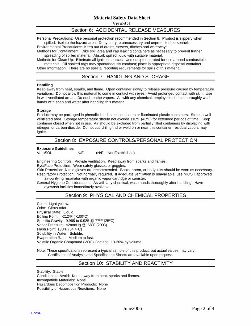
Material Safety Data Sheet VeruSOL
June2006 Page 2 of 4
Section 6: ACCIDENTAL RELEASE MEASURES
Personal Precautions: Use personal protection recommended in Section 8. Product is slippery when spilled. Isolate the hazard area. Deny entry to unnecessary and unprotected personnel.
Environmental Precautions: Keep out of drains, sewers, ditches and waterways. Methods for Containment: Dike spill area and cap leaking containers as necessary to prevent further
spreading of spilled material. Absorb spilled liquid with suitable material. Methods for Clean Up: Eliminate all ignition sources. Use equipment rated for use around combustible
materials. Oil soaked rags may spontaneously combust; place in appropriate disposal container. Other Information: There are no special reporting requirements for spills of this material.
Section 7: HANDLING AND STORAGE
Handling Keep away from heat, sparks, and flame. Open container slowly to release pressure caused by temperature variations. Do not allow this material to come in contact with eyes. Avoid prolonged contact with skin. Use in well ventilated areas. Do not breathe vapors. As with any chemical, employees should thoroughly wash hands with soap and water after handling this material. Storage Product may be packaged in phenolic-lined, steel containers or fluorinated plastic containers. Store in well ventilated area. Storage temperature should not exceed 110ºF (43ºC) for extended periods of time. Keep container closed when not in use. Air should be excluded from partially filled containers by displacing with nitrogen or carbon dioxide. Do not cut, drill, grind or weld on or near this container; residual vapors may ignite.
Section 8: EXPOSURE CONTROLS/PERSONAL PROTECTION
Exposure Guidelines VeruSOL N/E (N/E – Not Established) Engineering Controls: Provide ventilation. Keep away from sparks and flames. Eye/Face Protection: Wear safety glasses or goggles. Skin Protection: Nitrile gloves are recommended. Boots, apron, or bodysuits should be worn as necessary. Respiratory Protection: Not normally required. If adequate ventilation is unavailable, use NIOSH approved
air-purifying respirator with organic vapor cartridge or canister. General Hygiene Considerations: As with any chemical, wash hands thoroughly after handling. Have
eyewash facilities immediately available.
Section 9: PHYSICAL AND CHEMICAL PROPERTIES
Color: Light yellow. Odor: Citrus odor. Physical State: Liquid. Boiling Point: >212ºF (>100ºC) Specific Gravity: 0.968 to 0.985 @ 77ºF (25ºC) Vapor Pressure: <2mmHg @ 68ºF (20ºC) Flash Point: 130ºF (54.4ºC) Solubility in Water: Soluble. Evaporation Rate: Medium to fast. Volatile Organic Compound (VOC) Content: 10-30% by volume. Note: These specifications represent a typical sample of this product, but actual values may vary.
Certificates of Analysis and Specification Sheets are available upon request.
Section 10: STABILITY AND REACTIVITY
Stability: Stable. Conditions to Avoid: Keep away from heat, sparks and flames. Incompatible Materials: None Hazardous Decomposition Products: None Possibility of Hazardous Reactions: None
007284

Material Safety Data Sheet VeruSOL
June2006 Page 3 of 4
Section 11: TOXICOLOGICAL INFORMATION
Acute Effects An ingredient has been shown to have low oral toxicity (LD50>5 g/kg) and low dermal toxicity (LD50> 5g/kg) when tested on rabbits, It also showed low toxicity by inhalation (RD50>1 g/kg) when tested on mice. Product may be a skin and eye irritant. Inhalation may cause irritation of the nose, throat, and respiratory tract. Chronic Effects This product is not classified as a carcinogen by OSHA, IARC or NTP. This product has not been shown to produce genetic changes when tested on bacterial or animal cells. This product does not contain known reproductive or developmental toxins. Prolonged or repeated exposure can cause drying or dermatitis of skin. Improper storage and handling may lead to the formation of a possible skin sensitizer.
Section 12: ECOLOGICAL INFORMATION
Ecotoxicity: There is no information available at this time for this product. However, a spill may produce significant toxicity to aquatic organisms and ecosystems. Some studies have shown that certain bacteria and fungi have the ability to degrade terpenes, decreasing their toxicity to fish. When spilled, this product may act as an oil, causing a film, sheen, emulsion or sludge at or beneath the surface of a body of water.
Persistence/Degradability: Product is expected to be readily biodegradable. Bioaccumulation/Accumulation: No appreciable bioconcentration is expected in the environment. Mobility in Environment: Product volatilize rapidly.
Section 13: DISPOSAL CONSIDERATIONS
Disposal: Incinerate or dispose of in accordance with Local, State, and Federal Regulations. Taking regulations into consideration, waste may be incinerated or handled through EPA Spill Control Plan via landfill or dilution. Empty containers must be triple-rinsed prior to disposal.
Section 14: TRANSPORT INFORMATION
US DOT Shipping Classification Hazard Class: 3 Identification No.: UN2319 Packing Group: III Label/Placard: exception §173.150(f) applies. TDG Status: Hazardous IMO Status: Hazardous IATA Status: Hazardous The listed transportation classification does not address regulatory variations due to changes in package size, mode of shipment or other regulatory descriptions.
Section 15: REGULATORY INFORMATION
Global Inventories The components of this product are included in the following inventories: USA (TSCA) Canada (DSL) Australia (AICS) Korea (KECL) Philippines (PICCS) Proposition 65: California Safe Drinking Water and Toxic Enforcement Act of 1986 This product is not known to contain any chemicals currently listed as carcinogens or reproductive toxins under California Proposition 65 at levels which would be subject to the proposition.
007285
Material Safety Data Sheet VeruSOL
June2006 Page 4 of 4
Section 16: OTHER INFORMATION
NFPA 704: National Fire Protection Association Health – 1 (slight hazard) Fire – 2 (moderate hazard) Reactivity – 0 (minimal hazard)
Legend OSHA – United States Occupational Health and Safety Administration IARC – International Agency for Research on Cancer NTP – National Toxicology Program NIOSH – National Institute for Occupational Safety and Health EPA – United States Environmental Protection Agency Caution: The user should conduct his/her own experiments and establish proper procedures and
control before attempting use on critical parts.
The information contained herein is based on current knowledge and experience: no responsibility is accepted that the information is sufficient or correct in all cases. Users should consider these data only as a supplement to other information obtained by the user. No warranty is expressed or implied regarding the accuracy of this data, the results to be obtained from the use thereof, or that any such use will not infringe any patent. Users should make independent determinations of suitability and completeness of information from all sources to assure proper use and disposal of these materials, the safety and health of employees and customers, and the protection of the environment. This information is furnished upon the condition the person receiving it shall determine the suitability for the particular purpose. This MSDS is to be used as a guideline for safe work practices and emergency response.
007286
Page 1 of 11
MATERIAL SAFETY DATA SHEET Hydrogen Peroxide (20 to 40%)
MSDS Ref. No.: 7722-84-1-3 Date Approved: 06/03/2008 Revision No.: 11
This document has been prepared to meet the requirements of the U.S. OSHA Hazard Communication Standard, 29 CFR 1910.1200 and Canada’s Workplace Hazardous Materials Information System (WHMIS) requirements.
1. PRODUCT AND COMPANY IDENTIFICATION PRODUCT NAME: Hydrogen Peroxide (20 to 40%)
ALTERNATE PRODUCT NAME(S): Durox® Reg. & LR 35%, Oxypure® 35%, Standard 27.5 & 35%,
Super D® 25 & 35, Technical 35%, HTP 35%, OHP 35%, Chlorate
Grade, 20%, Semiconductor Reg, Seg, RGS, RGS 2, RGS 3, 31%
GENERAL USE: Durox® 35% Reg. & LR - meets the Food Chemical Codex
requirements for aseptic packaging and other food related
applications.
Oxypure® 35% - certified by NSF to meet NSF/ANSI Standard 60
requirements for drinking water treatment.
Standard 27.5 and 35% - most suitable grade for industrial bleaching,
processing, pollution abatement and general oxidation reactions.
Semiconductor Reg, Seg, RGS, RGS 2, RGS 3, 31% - conform to
ACS and Semi Specs. for wafer etching and cleaning, and
applications requiring low residues.
Super D® 25 and 35% - meets US Pharmacopoeia specifications for
3% topical solutions when diluted with proper quality water. While
manufactured to the USP standards for purity and to FMC's
demanding ISO 9002 quality standards, FMC does not claim that it's
Hydrogen Peroxide is manufactured in accordance with all
pharmaceutical cGMP conditions.
Technical 35% - essentially free of inorganic metals suitable for
chemical synthesis.
HTP 35% - specially formulated for aerospace equipment
conditioning.
OHP 35% - specially formulated for OHP process, advanced
oxidation, and activated peroxide applications
Chlorate Grade 20% - specially formulated for use in chlorate
manufacture or processing.
007287
Hydrogen Peroxide (20 to 40%) (7722-84-1-3) Date: 06/03/2008
Page 2 of 11
MANUFACTURER FMC CORPORATION FMC Peroxygens 1735 Market Street Philadelphia, PA 19103 (215) 299-6000 (General Information) [email protected] (Email - General Information) FMC of Canada Ltd. FMC Peroxygens PG Pulp Mill Road Prince George, BC V2N2S6 (250) 561-4200 (General Information)
EMERGENCY TELEPHONE NUMBERS (281) 474-8750 (Plant: Pasadena, TX, US - Call Collect) (250) 561-4221 (Plant: Prince George, BC, Canada - Call Collect) (303) 595-9048 (Medical - U.S. - Call Collect) For leak, fire, spill, or accident emergencies, call: (800) 424-9300 (CHEMTREC - U.S.A.) (613) 996-6666 (CANUTEC - Canada)
2. HAZARDS IDENTIFICATION EMERGENCY OVERVIEW: • Clear, colorless, odorless liquid • Oxidizer. • Contact with combustibles may cause fire. • Decomposes yielding oxygen that supports combustion of organic matters and can cause overpressure
if confined. • Corrosive to eyes, nose, throat, lungs and gastrointestinal tract.
POTENTIAL HEALTH EFFECTS: Corrosive to eyes, nose, throat and lungs. May cause irreversible tissue damage to the eyes including blindness. May cause skin irritation.
3. COMPOSITION / INFORMATION ON INGREDIENTS
Chemical Name CAS# Wt.% EC No. EC Class
Hydrogen Peroxide 7722-84-1 20 - 40 231-765-0 O, C, Xn; R5- R8-R35-R20/22
Water 7732-18-5 60 - 80 231-791-2 Not classified
007288
Hydrogen Peroxide (20 to 40%) (7722-84-1-3) Date: 06/03/2008
Page 3 of 11
4. FIRST AID MEASURES EYES: Immediately flush with water for at least 15 minutes, lifting the upper and lower eyelids intermittently. See a medical doctor or ophthalmologist immediately.
SKIN: Wash with plenty of soap and water. Get medical attention if irritation occurs and persists.
INGESTION: Rinse mouth with water. Dilute by giving 1 or 2 glasses of water. Do not induce vomiting. Never give anything by mouth to an unconscious person. See a medical doctor immediately.
INHALATION: Remove to fresh air. If breathing difficulty or discomfort occurs and persists, contact a medical doctor.
NOTES TO MEDICAL DOCTOR: Hydrogen peroxide at these concentrations is a strong oxidant. Direct contact with the eye is likely to cause corneal damage especially if not washed immediately. Careful ophthalmologic evaluation is recommended and the possibility of local corticosteroid therapy should be considered. Because of the likelihood of corrosive effects on the gastrointestinal tract after ingestion, and the unlikelihood of systemic effects, attempts at evacuating the stomach via emesis induction or gastric lavage should be avoided. There is a remote possibility, however, that a nasogastric or orogastric tube may be required for the reduction of severe distension due to gas formation.
5. FIRE FIGHTING MEASURES
EXTINGUISHING MEDIA: Flood with water.
FIRE / EXPLOSION HAZARDS: Product is non-combustible. On decomposition releases oxygen which may intensify fire.
FIRE FIGHTING PROCEDURES: Any tank or container surrounded by fire should be flooded with water for cooling. Wear full protective clothing and self-contained breathing apparatus.
FLAMMABLE LIMITS: Non-combustible
SENSITIVITY TO IMPACT: No data available
SENSITIVITY TO STATIC DISCHARGE: No data available
6. ACCIDENTAL RELEASE MEASURES
RELEASE NOTES: Dilute with a large volume of water and hold in a pond or diked area until hydrogen peroxide decomposes. Hydrogen peroxide may be decomposed by adding sodium metabisulfite or sodium sulfite after diluting to about 5%. Dispose according to methods outlined for waste disposal.
007289
Hydrogen Peroxide (20 to 40%) (7722-84-1-3) Date: 06/03/2008
Page 4 of 11
Combustible materials exposed to hydrogen peroxide should be immediately submerged in or rinsed with large amounts of water to ensure that all hydrogen peroxide is removed. Residual hydrogen peroxide that is allowed to dry (upon evaporation hydrogen peroxide can concentrate) on organic materials such as paper, fabrics, cotton, leather, wood or other combustibles can cause the material to ignite and result in a fire.
7. HANDLING AND STORAGE HANDLING: Wear chemical splash-type monogoggles and full-face shield, impervious clothing, such as rubber, PVC, etc., and rubber or neoprene gloves and shoes. Avoid cotton, wool and leather. Avoid excessive heat and contamination. Contamination may cause decomposition and generation of oxygen gas which could result in high pressures and possible container rupture. Hydrogen peroxide should be stored only in vented containers and transferred only in a prescribed manner (see FMC Technical Bulletins). Never return unused hydrogen peroxide to original container, empty drums should be triple rinsed with water before discarding. Utensils used for handling hydrogen peroxide should only be made of glass, stainless steel, aluminum or plastic.
STORAGE: Store drums in cool areas out of direct sunlight and away from combustibles. For bulk storage refer to FMC Technical Bulletins.
COMMENTS: VENTILATION: Provide mechanical general and/or local exhaust ventilation to prevent release of vapor or mist into the work environment.
8. EXPOSURE CONTROLS / PERSONAL PROTECTION EXPOSURE LIMITS
Chemical Name ACGIH OSHA Supplier
Hydrogen Peroxide
1 ppm (TWA)
1 ppm (PEL)
1.4 mg/m3 (PEL)
ENGINEERING CONTROLS: Ventilation should be provided to minimize the release of hydrogen peroxide vapors and mists into the work environment. Spills should be minimized or confined immediately to prevent release into the work area. Remove contaminated clothing immediately and wash before reuse.
PERSONAL PROTECTIVE EQUIPMENT
EYES AND FACE: Use chemical splash-type monogoggles and a full-face shield made of polycarbonate, acetate, polycarbonate/acetate, PETG or thermoplastic.
RESPIRATORY: If concentrations in excess of 10 ppm are expected, use NIOSH/DHHS approved self-contained breathing apparatus (SCBA), or other approved atmospheric-supplied respirator (ASR) equipment (e.g., a full-face airline respirator (ALR)). DO NOT use any form of air-purifying respirator (APR) or filtering facepiece (AKA dust mask), especially those containing oxidizable sorbants such as activated carbon.
007290
Hydrogen Peroxide (20 to 40%) (7722-84-1-3) Date: 06/03/2008
Page 5 of 11
PROTECTIVE CLOTHING: For body protection wear impervious clothing such as an approved splash protective suit made of SBR Rubber, PVC (PVC Outershell w/Polyester Substrate), Gore-Tex (Polyester trilaminate w/Gore-Tex), or a specialized HAZMAT Splash or Protective Suite (Level A, B, or C). For foot protection, wear approved boots made of NBR, PVC, Polyurethane, or neoprene. Overboots made of Latex or PVC, as well as firefighter boots or specialized HAZMAT boots are also permitted. DO NOT wear any form of boot or overboots made of nylon or nylon blends. DO NOT use cotton, wool or leather, as these materials react RAPIDLY with higher concentrations of hydrogen peroxide. Completely submerge hydrogen peroxide contaminated clothing or other materials in water prior to drying. Residual hydrogen peroxide, if allowed to dry on materials such as paper, fabrics, cotton, leather, wood or other combustibles can cause the material to ignite and result in a fire.
GLOVES: For hand protection, wear approved gloves made of nitrile, PVC, or neoprene. DO NOT use cotton, wool or leather for these materials react RAPIDLY with higher concentrations of hydrogen peroxide. Thoroughly rinse the outside of gloves with water prior to removal. Inspect regularly for leaks.
9. PHYSICAL AND CHEMICAL PROPERTIES ODOR: Odorless
APPEARANCE: Clear, colorless liquid
AUTOIGNITION TEMPERATURE: Non-combustible
BOILING POINT: 103ºC/218ºF (20%); 107ºC/225ºF (31%); 108ºC/226ºF
(35%)
COEFFICIENT OF OIL / WATER: Not available
DENSITY / WEIGHT PER VOLUME: Not available
EVAPORATION RATE: > 1 (Butyl Acetate = 1)
FLASH POINT: Non-combustible
FREEZING POINT: -15ºC/6ºF (20%); -26ºC/-15ºF (31%); -33ºC/-27ºF (35%)
ODOR THRESHOLD: Not available
OXIDIZING PROPERTIES: Strong oxidizer
PERCENT VOLATILE: 100
pH: <= 3.7
5.0 - 6.0 @ 25 °C (1% solution)
SOLUBILITY IN WATER: 100 %
SPECIFIC GRAVITY: 1.07 @ 20ºC/4ºC (20%); 1.11 @ 20ºC/4ºC (31%); 1.13 @
20ºC/4ºC (35%)
VAPOR DENSITY: (Air = 1): Not available
VAPOR PRESSURE: 28 mmHg @ 30ºC (20%); 24 mmHg @ 30ºC (31%); 23
mmHg @ 30ºC (35%)
007291
Hydrogen Peroxide (20 to 40%) (7722-84-1-3) Date: 06/03/2008
Page 6 of 11
10. STABILITY AND REACTIVITY CONDITIONS TO AVOID: Excessive heat or contamination could cause
product to become unstable.
STABILITY: Stable (heat and contamination could cause decomposition)
POLYMERIZATION: Will not occur
INCOMPATIBLE MATERIALS: Reducing agents, wood, paper and other combustibles, iron and other heavy metals, copper alloys and caustic.
HAZARDOUS DECOMPOSITION PRODUCTS: Oxygen which supports combustion.
COMMENTS: Materials to Avoid : Dirt, organics, cyanides and combustibles such as wood, paper, oils, etc.
11. TOXICOLOGICAL INFORMATION EYE EFFECTS: 35% hydrogen peroxide: Extremely irritating/corrosive (rabbit) [FMC Study Number: I83-748]
SKIN EFFECTS: 35% hydrogen peroxide: Mildly irritating after 4-hour exposure (rabbit) [FMC Study Number: I83-747]
DERMAL LD50: 35% hydrogen peroxide: > 2,000 mg/kg (rabbit) [FMC Study Number: I83-746]
ORAL LD50: 35% hydrogen peroxide: 1,193 mg/kg (rat) [FMC Study Number: I83-745]
INHALATION LC50: 50% hydrogen peroxide: > 0.17 mg/l (rat) [FMC Study Number: I89-1080]
TARGET ORGANS: Eyes, nose, throat and lungs
ACUTE EFFECTS FROM OVEREXPOSURE: Extremely irritating/corrosive to eyes and gastrointestinal tract. May cause irreversible tissue damage to the eyes including blindness. Inhalation of mist or vapors may be severely irritating to nose, throat and lungs. May cause skin irritation.
CHRONIC EFFECTS FROM OVEREXPOSURE: The International Agency for Research on Cancer (IARC) has concluded that there is inadequate evidence for carcinogenicity of hydrogen peroxide in humans, but limited evidence in experimental animals (Group 3 - not classifiable as to its carcinogenicity to humans). The American Conference of Governmental Industrial Hygienists (ACGIH) has concluded that hydrogen peroxide is a ’Confirmed Animal Carcinogen with Unknown Relevance to Humans’ (A3).
007292
Hydrogen Peroxide (20 to 40%) (7722-84-1-3) Date: 06/03/2008
Page 7 of 11
CARCINOGENICITY: Chemical Name IARC NTP OSHA Other Hydrogen Peroxide Not listed Not listed Not listed (ACGIH) Listed (A3,
Animal Carcinogen)
12. ECOLOGICAL INFORMATION ECOTOXICOLOGICAL INFORMATION: Channel catfish 96-hour LC50 = 37.4 mg/L Fathead minnow 96-hour LC50 = 16.4 mg/L Daphnia magna 24-hour EC50 = 7.7 mg/L Daphnia pulex 48-hour LC50 = 2.4 mg/L Freshwater snail 96-hour LC50 = 17.7 mg/L For more information refer to ECETOC "Joint Assessment of Commodity Chemicals No. 22, Hydrogen Peroxide." ISSN-0773-6339, January 1993
CHEMICAL FATE INFORMATION: Hydrogen peroxide in the aquatic environment is subject to various reduction or oxidation processes and decomposes into water and oxygen. Hydrogen peroxide half-life in freshwater ranged from 8 hours to 20 days, in air from 10-20 hrs. and in soils from minutes to hours depending upon microbiological activity and metal contaminants.
13. DISPOSAL CONSIDERATIONS DISPOSAL METHOD: An acceptable method of disposal is to dilute with a large amount of water and allow the hydrogen peroxide to decompose followed by discharge into a suitable treatment system in accordance with all regulatory agencies. The appropriate regulatory agencies should be contacted prior to disposal.
14. TRANSPORT INFORMATION U.S. DEPARTMENT OF TRANSPORTATION (DOT)
PROPER SHIPPING NAME: Hydrogen peroxide, aqueous solutions with not less than 20% but not more than 40% hydrogen peroxide
PRIMARY HAZARD CLASS / DIVISION: 5.1 (Oxidizer)
UN/NA NUMBER: UN 2014
PACKING GROUP: II
LABEL(S): Oxidizer, Corrosive
PLACARD(S): 5.1 (Oxidizer)
007293
Hydrogen Peroxide (20 to 40%) (7722-84-1-3) Date: 06/03/2008
Page 8 of 11
ADDITIONAL INFORMATION: DOT Marking: Hydrogen Peroxide, aqueous solution with not less than 20%, but not more than 40% Hydrogen Peroxide, UN 2014
Hazardous Substance/RQ: Not applicable
49 STCC Number: 4918775
DOT Spec: stainless steel/high purity aluminum cargo tanks and rail cars. UN Spec: HDPE drums. Contact FMC for specific details.
INTERNATIONAL MARITIME DANGEROUS GOODS (IMDG)
PROPER SHIPPING NAME: Hydrogen peroxide, aqueous solutions with not less than 20%, but not more than 60% hydrogen peroxide.
INTERNATIONAL CIVIL AVIATION ORGANIZATION (ICAO) / INTERNATIONAL AIR TRANSPORT ASSOCIATION (IATA)
PROPER SHIPPING NAME: Hydrogen peroxide, aqueous solutions with not less than 20%, but not more than 40% hydrogen peroxide (*).
OTHER INFORMATION: (*) Air regulations permit shipment of Hydrogen Peroxide (20 - 40%) in non-vented containers for Air Cargo Only aircraft, as well as for Passenger and Cargo aircraft. HOWEVER, all FMC Hydrogen Peroxide containers are vented and therefore, air shipments of FMC H202 is not permitted. IATA air regulations state that venting of packages containing oxidizing substances is not permitted for air transport. Protect from physical damage. Keep drums in upright position. Drums should not be stacked in transit. Do not store drum on wooden pallets.
15. REGULATORY INFORMATION
UNITED STATES
SARA TITLE III (SUPERFUND AMENDMENTS AND REAUTHORIZATION ACT)
SECTION 302 EXTREMELY HAZARDOUS SUBSTANCES (40 CFR 355, APPENDIX A): Not listed
SECTION 311 HAZARD CATEGORIES (40 CFR 370):
Fire Hazard, Immediate (Acute) Health Hazard
007294
Hydrogen Peroxide (20 to 40%) (7722-84-1-3) Date: 06/03/2008
Page 9 of 11
SECTION 312 THRESHOLD PLANNING QUANTITY (40 CFR 370): The Threshold Planning Quantity (TPQ) for this product, if treated as a mixture, is 10,000 lbs; however, this product contains the following ingredients with a TPQ of less than 10,000 lbs.: None, (conc. <52%)
SECTION 313 REPORTABLE INGREDIENTS (40 CFR 372):
Not listed
CERCLA (COMPREHENSIVE ENVIRONMENTAL RESPONSE COMPENSATION AND LIABILITY ACT)
CERCLA DESIGNATION & REPORTABLE QUANTITIES (RQ) (40 CFR 302.4): Unlisted (Hydrogen Peroxide 20-40%); RQ = 100 lbs.; Ignitability, Corrosivity
TSCA (TOXIC SUBSTANCE CONTROL ACT)
TSCA INVENTORY STATUS (40 CFR 710): Listed
RESOURCE CONSERVATION AND RECOVERY ACT (RCRA) RCRA IDENTIFICATION OF HAZARDOUS WASTE (40 CFR 261):
Waste Number: D001, D002
CANADA WHMIS (WORKPLACE HAZARDOUS MATERIALS INFORMATION SYSTEM):
This product has been classified in accordance with the hazard criteria of the Controlled Products Regulations and the MSDS contains all the information required by the Controlled Products Regulations. Hazard Classification / Division: C E D2B Product Identification Number: 2014 Ingredient Disclosure List: Listed Domestic Substance List: All components listed
INTERNATIONAL LISTINGS Hydrogen peroxide: China: Listed Japan (ENCS): (1)-419 Korea: KE-20204 Philippines (PICCS): Listed
HAZARD AND RISK PHRASE DESCRIPTIONS:
EC Symbols: O (Oxidizer)
007295
Hydrogen Peroxide (20 to 40%) (7722-84-1-3) Date: 06/03/2008
Page 10 of 11
C (Corrosive) Xn (Harmful) EC Risk Phrases: R5 (Heating may cause an explosion.) R8 (Contact with combustible material may cause fire) R35 (Causes severe burns.) R20/22 (Harmful by inhalation and if swallowed.)
16. OTHER INFORMATION HMIS
Health 3 Flammability 0 Physical Hazard 1 Personal Protection (PPE) H
Protection = H (Safety goggles, gloves, apron, the use of a supplied air or SCBA respirator is required in lieu of a vapor cartridge respirator)
HMIS = Hazardous Materials Identification System Degree of Hazard Code: 4 = Severe 3 = Serious 2 = Moderate 1 = Slight 0 = Minimal NFPA
Health 3 Flammability 0 Reactivity 1 Special OX
SPECIAL = OX (Oxidizer) NFPA (National Fire Protection Association) Degree of Hazard Code: 4 = Extreme 3 = High 2 = Moderate 1 = Slight 0 = Insignificant REVISION SUMMARY: This MSDS replaces Revision #10, dated April 27, 2006.
007296
Hydrogen Peroxide (20 to 40%) (7722-84-1-3) Date: 06/03/2008
Page 11 of 11
Changes in information are as follows: Section 1 (Product and Company Identification) Section 3 (Composition / Information on Ingredients) Section 15 (Regulatory Information) Section 16 (Other Information) Durox, Oxypure, Super D and FMC Logo - FMC Trademarks © 2008 FMC Corporation. All Rights Reserved.
FMC Corporation believes that the information and recommendations contained herein (including data and
statements) are accurate as of the date hereof. NO WARRANTY OF FITNESS FOR ANY PARTICULAR
PURPOSE, WARRANTY OF MERCHANTABILITY, OR ANY OTHER WARRANTY, EXPRESSED
OR IMPLIED, IS MADE CONCERNING THE INFORMATION PROVIDED HEREIN. The information
provided herein relates only to the specific product designated and may not be applicable where such
product is used in combination with any other materials or in any process. It is a violation of Federal law to
use this product in a manner inconsistent with its labeling. Further, since the conditions and methods of use
are beyond the control of FMC Corporation, FMC Corporation expressly disclaims any and all liability as
to any results obtained or arising from any use of the product or reliance on such information.
007297
Material Safety Data SheetFerrous sulfate MSDS
Section 1: Chemical Product and Company Identification
Product Name: Ferrous sulfate
Catalog Codes: SLF1516
CAS#: 13463-43-9
RTECS: Not available.
TSCA: TSCA 8(b) inventory: No products were found.
CI#: Not available.
Synonym: Ferrous Sulfate Hydrate; Ferrous Sulfate DriedPowder
Chemical Name: Ferrous Sulfate
Chemical Formula: FeSO4.xH2O
Contact Information:
Sciencelab.com, Inc.14025 Smith Rd.Houston, Texas 77396
US Sales: 1-800-901-7247International Sales: 1-281-441-4400
Order Online: ScienceLab.com
CHEMTREC (24HR Emergency Telephone), call:1-800-424-9300
International CHEMTREC, call: 1-703-527-3887
For non-emergency assistance, call: 1-281-441-4400
Section 2: Composition and Information on IngredientsComposition:
Name CAS # % by Weight
Ferrous sulfate 13463-43-9 100
Toxicological Data on Ingredients: Ferrous sulfate LD50: Not available. LC50: Not available.
Section 3: Hazards Identification
Potential Acute Health Effects: Hazardous in case of skin contact (irritant), of eye contact (irritant), of ingestion, of inhalation.
Potential Chronic Health Effects:CARCINOGENIC EFFECTS: Not available.MUTAGENIC EFFECTS: Not available.TERATOGENIC EFFECTS: Not available.DEVELOPMENTAL TOXICITY: Not available.The substance may be toxic to kidneys, liver, cardiovascular system, central nervous system (CNS).Repeated or prolonged exposure to the substance can produce target organs damage.
Section 4: First Aid Measures
Eye Contact:
p. 1007298
Check for and remove any contact lenses. In case of contact, immediately flush eyes with plenty of water for atleast 15 minutes. Cold water may be used. Get medical attention.
Skin Contact:In case of contact, immediately flush skin with plenty of water. Cover the irritated skin with an emollient. Removecontaminated clothing and shoes. Cold water may be used.Wash clothing before reuse. Thoroughly clean shoesbefore reuse. Get medical attention.
Serious Skin Contact:Wash with a disinfectant soap and cover the contaminated skin with an anti-bacterial cream. Seek medicalattention.
Inhalation:If inhaled, remove to fresh air. If not breathing, give artificial respiration. If breathing is difficult, give oxygen. Getmedical attention.
Serious Inhalation: Not available.
Ingestion:Do NOT induce vomiting unless directed to do so by medical personnel. Never give anything by mouth to anunconscious person. If large quantities of this material are swallowed, call a physician immediately. Loosen tightclothing such as a collar, tie, belt or waistband.
Serious Ingestion: Not available.
Section 5: Fire and Explosion Data
Flammability of the Product: Non-flammable.
Auto-Ignition Temperature: Not applicable.
Flash Points: Not applicable.
Flammable Limits: Not applicable.
Products of Combustion: Not available.
Fire Hazards in Presence of Various Substances: Not applicable.
Explosion Hazards in Presence of Various Substances:Risks of explosion of the product in presence of mechanical impact: Not available.Risks of explosion of the product in presence of static discharge: Not available.
Fire Fighting Media and Instructions: Not applicable.
Special Remarks on Fire Hazards: Not available.
Special Remarks on Explosion Hazards: Not available.
Section 6: Accidental Release Measures
Small Spill:Use appropriate tools to put the spilled solid in a convenient waste disposal container. Finish cleaning byspreading water on the contaminated surface and dispose of according to local and regional authorityrequirements.
Large Spill:Use a shovel to put the material into a convenient waste disposal container. Finish cleaning by spreading wateron the contaminated surface and allow to evacuate through the sanitary system. Be careful that the product is notpresent at a concentration level above TLV. Check TLV on the MSDS and with local authorities.
p. 2007299
Section 7: Handling and Storage
Precautions:Do not breathe dust. Wear suitable protective clothing. In case of insufficient ventilation, wear suitable respiratoryequipment. If you feel unwell, seek medical attention and show the label when possible. Avoid contact with skinand eyes.
Storage:Hygroscopic. Keep container tightly closed. Keep container in a cool, well-ventilated area. Do not store above24°C (75.2°F).
Section 8: Exposure Controls/Personal Protection
Engineering Controls:Use process enclosures, local exhaust ventilation, or other engineering controls to keep airborne levels belowrecommended exposure limits. If user operations generate dust, fume or mist, use ventilation to keep exposure toairborne contaminants below the exposure limit.
Personal Protection:Splash goggles. Lab coat. Dust respirator. Be sure to use an approved/certified respirator or equivalent.Gloves.
Personal Protection in Case of a Large Spill:Splash goggles. Full suit. Dust respirator. Boots. Gloves. A self contained breathing apparatus should be usedto avoid inhalation of the product. Suggested protective clothing might not be sufficient; consult a specialistBEFORE handling this product.
Exposure Limits: Not available.
Section 9: Physical and Chemical Properties
Physical state and appearance: Solid.
Odor: Not available.
Taste: Not available.
Molecular Weight: 151.9 g/mole + H20
Color: Grayish -white to yellowish. (Light.)
pH (1% soln/water): Not available.
Boiling Point: Not available.
Melting Point: Not available.
Critical Temperature: Not available.
Specific Gravity: Not available.
Vapor Pressure: Not applicable.
Vapor Density: Not available.
Volatility: Not available.
Odor Threshold: Not available.
Water/Oil Dist. Coeff.: Not available.
p. 3007300
Ionicity (in Water): Not available.
Dispersion Properties: See solubility in water.
Solubility: Soluble in cold water.
Section 10: Stability and Reactivity Data
Stability: The product is stable.
Instability Temperature: Not available.
Conditions of Instability: Incompatibles
Incompatibility with various substances: Not available.
Corrosivity: Not available.
Special Remarks on Reactivity:Hygroscopic.Loses water at about 300 C.
No other information found.
Special Remarks on Corrosivity: Not available.
Polymerization: Will not occur.
Section 11: Toxicological Information
Routes of Entry: Inhalation. Ingestion.
Toxicity to Animals:LD50: Not available.LC50: Not available.
Chronic Effects on Humans: May cause damage to the following organs: kidneys, liver, cardiovascular system, centralnervous system (CNS).
Other Toxic Effects on Humans: Hazardous in case of skin contact (irritant), of ingestion, of inhalation.
Special Remarks on Toxicity to Animals: Not available.
Special Remarks on Chronic Effects on Humans: May affect genetic material (mutagenic)
Special Remarks on other Toxic Effects on Humans:Acute Potential Health Effects:Skin: May cause skin irritation.Eyes: May cause eye irritation.Inhalation: May cause respiratory tract irritation.Ingestion: Harmful if swallowed. May cause gastrointestinal tract distrubances and irritation with nausea,vomiting, colic, constipation, diarrhea, black stool. May also affect behavior/Central Nervous System (somnolence-general depressed activity), respiration, cardiovascular system, liver, kidneys (pink urine discoloration).Chronic Potential Health Effects: Repeated exposure via ingestion may increase iron levels in the liver, andspleen. Damage may occur to spleen and liver.
Section 12: Ecological Information
Ecotoxicity: Not available.
p. 4007301
BOD5 and COD: Not available.
Products of Biodegradation:Possibly hazardous short term degradation products are not likely. However, long term degradation products mayarise.
Toxicity of the Products of Biodegradation: The product itself and its products of degradation are not toxic.
Special Remarks on the Products of Biodegradation: Not available.
Section 13: Disposal Considerations
Waste Disposal:Waste must be disposed of in accordance with federal, state and local environmentalcontrol regulations.
Section 14: Transport Information
DOT Classification: Not a DOT controlled material (United States).
Identification: Not applicable.
Special Provisions for Transport: Not applicable.
Section 15: Other Regulatory Information
Federal and State Regulations: No products were found.
Other Regulations: OSHA: Hazardous by definition of Hazard Communication Standard (29 CFR 1910.1200).
Other Classifications:
WHMIS (Canada): Not controlled under WHMIS (Canada).
DSCL (EEC):R36/38- Irritating to eyes and skin.S2- Keep out of the reach of children.S46- If swallowed, seek medical adviceimmediately and show this container or label.
HMIS (U.S.A.):
Health Hazard: 2
Fire Hazard: 0
Reactivity: 0
Personal Protection: E
National Fire Protection Association (U.S.A.):
Health: 2
Flammability: 0
Reactivity: 0
p. 5007302
Specific hazard:
Protective Equipment:Gloves.Lab coat.Dust respirator. Be sure to use anapproved/certified respirator orequivalent.Splash goggles.
Section 16: Other Information
References: Not available.
Other Special Considerations: Not available.
Created: 10/09/2005 05:33 PM
Last Updated: 11/06/2008 12:00 PM
The information above is believed to be accurate and represents the best information currently available to us. However, wemake no warranty of merchantability or any other warranty, express or implied, with respect to such information, and weassume no liability resulting from its use. Users should make their own investigations to determine the suitability of theinformation for their particular purposes. In no event shall ScienceLab.com be liable for any claims, losses, or damages of anythird party or for lost profits or any special, indirect, incidental, consequential or exemplary damages, howsoever arising, evenif ScienceLab.com has been advised of the possibility of such damages.
p. 6007303
Material Safety Data SheetPhosphoric acid, 85% MSDS
Section 1: Chemical Product and Company Identification
Product Name: Phosphoric acid, 85%
Catalog Codes: SLP5569, SLP4555, SLP1732
CAS#: Mixture.
RTECS: Not applicable.
TSCA: TSCA 8(b) inventory: Phosphoric Acid; Water
CI#: Not available.
Synonym: Phosphoric Acid 85%; Phosphoric Acid;Orthophosphoric acid
Chemical Name: Not applicable.
Chemical Formula: Not applicable.
Contact Information:
Sciencelab.com, Inc.14025 Smith Rd.Houston, Texas 77396
US Sales: 1-800-901-7247International Sales: 1-281-441-4400
Order Online: ScienceLab.com
CHEMTREC (24HR Emergency Telephone), call:1-800-424-9300
International CHEMTREC, call: 1-703-527-3887
For non-emergency assistance, call: 1-281-441-4400
Section 2: Composition and Information on IngredientsComposition:
Name CAS # % by Weight
Phosphoric Acid 7664-38-2 85-88
Water 7732-18-5 12-15
Toxicological Data on Ingredients: Phosphoric Acid: ORAL (LD50): Acute: 1530 mg/kg [Rat]. DERMAL (LD50): Acute: 2740mg/kg [Rabbit]. DUST (LC50): Acute: >850 mg/m 1 hours [Rat].
Section 3: Hazards Identification
Potential Acute Health Effects:Very hazardous in case of skin contact (irritant), of eye contact (irritant), of ingestion, . Hazardous in case of skincontact (corrosive, permeator), of eye contact (corrosive). Slightly hazardous in case of inhalation (lungsensitizer). Liquid or spray mist may produce tissue damage particularly on mucous membranes of eyes, mouthand respiratory tract. Skin contact may produce burns. Inhalation of the spray mist may produce severe irritationof respiratory tract, characterized by coughing, choking, or shortness of breath. Severe over-exposure can resultin death. Inflammation of the eye is characterized by redness, watering, and itching. Skin inflammation ischaracterized by itching, scaling, reddening, or, occasionally, blistering.
Potential Chronic Health Effects:CARCINOGENIC EFFECTS: Not available.
p. 1007304
MUTAGENIC EFFECTS: Not available.TERATOGENIC EFFECTS: Not available.DEVELOPMENTAL TOXICITY: Not available.The substance may be toxic to blood, liver, skin, eyes, bone marrow.Repeated or prolonged exposure to the substance can produce target organs damage. Repeated or prolongedcontact with spray mist may produce chronic eye irritation and severe skin irritation. Repeated or prolongedexposure to spray mist may produce respiratory tract irritation leading to frequent attacks of bronchial infection.Repeated exposure to a highly toxic material may produce general deterioration of health by an accumulation inone or many human organs.
Section 4: First Aid Measures
Eye Contact:Check for and remove any contact lenses. In case of contact, immediately flush eyes with plenty of water for atleast 15 minutes. Cold water may be used. Get medical attention immediately.
Skin Contact:In case of contact, immediately flush skin with plenty of water for at least 15 minutes while removing contaminatedclothing and shoes. Cover the irritated skin with an emollient. Cold water may be used.Wash clothing beforereuse. Thoroughly clean shoes before reuse. Get medical attention immediately.
Serious Skin Contact:Wash with a disinfectant soap and cover the contaminated skin with an anti-bacterial cream. Seek immediatemedical attention.
Inhalation:If inhaled, remove to fresh air. If not breathing, give artificial respiration. If breathing is difficult, give oxygen. Getmedical attention immediately.
Serious Inhalation:Evacuate the victim to a safe area as soon as possible. Loosen tight clothing such as a collar, tie, belt orwaistband. If breathing is difficult, administer oxygen. If the victim is not breathing, perform mouth-to-mouthresuscitation. WARNING: It may be hazardous to the person providing aid to give mouth-to-mouth resuscitationwhen the inhaled material is toxic, infectious or corrosive. Seek immediate medical attention.
Ingestion:Do NOT induce vomiting unless directed to do so by medical personnel. Never give anything by mouth to anunconscious person. If large quantities of this material are swallowed, call a physician immediately. Loosen tightclothing such as a collar, tie, belt or waistband.
Serious Ingestion: Not available.
Section 5: Fire and Explosion Data
Flammability of the Product: Non-flammable.
Auto-Ignition Temperature: Not applicable.
Flash Points: Not applicable.
Flammable Limits: Not applicable.
Products of Combustion: Not available.
Fire Hazards in Presence of Various Substances: of metals
Explosion Hazards in Presence of Various Substances: Non-explosive in presence of open flames and sparks, of shocks.
Fire Fighting Media and Instructions: Not applicable.
p. 2007305
Special Remarks on Fire Hazards:Reacts with metals to liberate flammable hydrogen gas.Formation of flammable gases with aldehydes, cyanides, mercaptins, and sulfides.
Special Remarks on Explosion Hazards: Mixtures with nitromethane are explosive. (Phosphoric Acid)
Section 6: Accidental Release Measures
Small Spill:Dilute with water and mop up, or absorb with an inert dry material and place in an appropriate waste disposalcontainer. If necessary: Neutralize the residue with a dilute solution of sodium carbonate.
Large Spill:Corrosive liquid. Poisonous liquid.Stop leak if without risk. Absorb with DRY earth, sand or other non-combustible material. Do not get water insidecontainer. Do not touch spilled material. Use water spray curtain to divert vapor drift. Use water spray to reducevapors. Prevent entry into sewers, basements or confined areas; dike if needed. Call for assistance on disposal.Neutralize the residue with a dilute solution of sodium carbonate. Be careful that the product is not present ata concentration level above TLV. Check TLV on the MSDS and with local authorities.
Section 7: Handling and Storage
Precautions:Do not ingest. Do not breathe gas/fumes/ vapor/spray. Never add water to this product. In case of insufficientventilation, wear suitable respiratory equipment. If ingested, seek medical advice immediately and show thecontainer or the label. Avoid contact with skin and eyes. Keep away from incompatibles such as oxidizing agents,combustible materials, metals, alkalis.May corrode metallic surfaces. Store in a metallic or coated fiberboard drum using a strong polyethylene innerpackage.
Storage: Keep container tightly closed. Keep container in a cool, well-ventilated area.
Section 8: Exposure Controls/Personal Protection
Engineering Controls:Provide exhaust ventilation or other engineering controls to keep the airborne concentrations of vapors below theirrespective threshold limit value. Ensure that eyewash stations and safety showers are proximal to thework-station location.
Personal Protection:Face shield. Full suit. Vapor respirator. Be sure to use an approved/certified respirator or equivalent. Gloves.Boots.
Personal Protection in Case of a Large Spill:Splash goggles. Full suit. Vapor respirator. Boots. Gloves. A self contained breathing apparatus should beused to avoid inhalation of the product. Suggested protective clothing might not be sufficient; consult a specialistBEFORE handling this product.
Exposure Limits:Phosphoric AcidTWA: 1 STEL: 3 (mg/m3) from ACGIH (TLV) [United States]TWA: 1 STEL: 3 (mg/m3) from OSHA (PEL) [United States]TWA: 1 STEL: 3 (mg/m3) from NIOSHTWA: 1 STEL: 3 (mg/m3) [Mexico]Consult local authorities for acceptable exposure limits.
Section 9: Physical and Chemical Properties
p. 3007306
Physical state and appearance: Liquid. (Syrupy liquid Viscous liquid.)
Odor: Odorless.
Taste: Acid.
Molecular Weight: Not applicable.
Color: Clear Colorless.
pH (1% soln/water): Acidic.
Boiling Point: 158°C (316.4°F)
Melting Point: 21°C (69.8°F)
Critical Temperature: Not available.
Specific Gravity: 1.685 @ 25 C (Water = 1)
Vapor Pressure: 0.3 kPa (@ 20°C)
Vapor Density: 3.4 (Air = 1)
Volatility: Not available.
Odor Threshold: Not available.
Water/Oil Dist. Coeff.: Not available.
Ionicity (in Water): Not available.
Dispersion Properties: See solubility in water.
Solubility:Easily soluble in hot water.Soluble in cold water.
Section 10: Stability and Reactivity Data
Stability: The product is stable.
Instability Temperature: Not available.
Conditions of Instability: Incompatible materials
Incompatibility with various substances: Reactive with oxidizing agents, combustible materials, metals, alkalis.
Corrosivity:Extremely corrosive in presence of copper, of stainless steel(304), of stainless steel(316).Highly corrosive in presence of aluminum.Non-corrosive in presence of glass.
Special Remarks on Reactivity:Reacts with metals to liberate flammable hydrogen gas.Incompatible with sodium tetrahydroborate producing a violent exothermic reaction.Heat generated with: alcohols, glycols, aldehydes, amides, amines, azo-compounds, carbamates, caustics,esters, ketones, phenols and cresols, organophosphates, epoxides, combustible materials, unsaturated halides,organic peroxides.Formation of flammable gases, with aldehydes, cyanides, mercaptins, and sulfides.
p. 4007307
Formation of toxic fumes with cyanides, fluorides, halogenated organics, sulfides, and organic peroxides.Do not mix with solutions containing bleach or ammonia.Incompatible with nitromethane, chlorides + staiinless steel.(Phosphoric Acid)
Special Remarks on Corrosivity:Minor corrosive effect on bronze.Severe corrosive effect on brass.Corrosive to ferrous metals and alloys.
Polymerization: Will not occur.
Section 11: Toxicological Information
Routes of Entry: Absorbed through skin. Dermal contact. Eye contact. Inhalation. Ingestion.
Toxicity to Animals:Acute oral toxicity (LD50): 1530 mg/kg [Rat].Acute dermal toxicity (LD50): 2740 mg/kg [Rabbit].
Chronic Effects on Humans: May cause damage to the following organs: blood, liver, skin, eyes, bone marrow.
Other Toxic Effects on Humans:Extremely hazardous in case of inhalation (lung corrosive).Very hazardous in case of skin contact (irritant), of ingestion, .Hazardous in case of skin contact (corrosive, permeator), of eye contact (corrosive).
Special Remarks on Toxicity to Animals: Not available.
Special Remarks on Chronic Effects on Humans: Not available.
Special Remarks on other Toxic Effects on Humans:Acute Potential Health Effects:Skin: Corrosive and causes severe skin irritation and can cause severe skin burns. May affect behavior(somnolence or excitement) if absorbed through skin.Eyes: Corrosive. Liquid or vapor causes severe eye irritation and can cause severe eye burns leading topermanent corneal damage or chemical conjunctivitis.Ingestion: May be harmful if swallowed. Causes irritation and burns of the gastrointestinal (digestive) tract.Causes severe pain, nausea, vomiting, diarrhea hematemesis, gastrointestinal hemmorrhaging, and shock. Maycause corrosion and permanent tissue destruction of the esophagus and digestive tract. May affect behavior andurinary system, liver (hepatocellular damage, hepatic enzymes increased), blood (blood dyscrasia). May also
Section 12: Ecological Information
Ecotoxicity: Not available.
BOD5 and COD: Not available.
Products of Biodegradation:Possibly hazardous short term degradation products are not likely. However, long term degradation products mayarise.
Toxicity of the Products of Biodegradation: The products of degradation are less toxic than the product itself.
Special Remarks on the Products of Biodegradation: Not available.
Section 13: Disposal Considerations
Waste Disposal:
p. 5007308
Waste must be disposed of in accordance with federal, state and local environmentalcontrol regulations.
Section 14: Transport Information
DOT Classification: Class 8: Corrosive material
Identification: : Phosphoric acid (Phosphoric Acid) UNNA: 1805 PG: III
Special Provisions for Transport: Not available.
Section 15: Other Regulatory Information
Federal and State Regulations:Connecticut hazardous material survey.: Phosphoric AcidIllinois toxic substances disclosure to employee act: Phosphoric acidIllinois chemical safety act: Phosphoric acidNew York release reporting list: Phosphoric acidRhode Island RTK hazardous substances: Phosphoric acidPennsylvania RTK: Phosphoric acidMinnesota: Phosphoric acidMassachusetts RTK: Phosphoric acidMassachusetts spill list: Phosphoric acidNew Jersey: Phosphoric acidNew Jersey spill list: Phosphoric acidLouisiana spill reporting: Phosphoric acidCalifornia Director's list of hazardous substances: Phosphoric acidTSCA 8(b) inventory: Phosphoric Acid; WaterSARA 313 toxic chemical notification and release reporting: Phosphoric acidCERCLA: Hazardous substances.: Phosphoric acid: 5000 lbs. (2268 kg)
Other Regulations: OSHA: Hazardous by definition of Hazard Communication Standard (29 CFR 1910.1200).
Other Classifications:
WHMIS (Canada): CLASS E: Corrosive liquid.
DSCL (EEC):R34- Causes burns.S26- In case of contact with eyes, rinseimmediately with plenty of water and seekmedical advice.S45- In case of accident or if you feel unwell,seek medical advice immediately (show thelabel where possible).
HMIS (U.S.A.):
Health Hazard: 3
Fire Hazard: 0
Reactivity: 0
Personal Protection:
National Fire Protection Association (U.S.A.):
Health: 3
p. 6007309
Flammability: 0
Reactivity: 0
Specific hazard:
Protective Equipment:Gloves.Full suit.Vapor respirator. Be sure to use anapproved/certified respirator orequivalent. Wear appropriate respiratorwhen ventilation is inadequate.Face shield.
Section 16: Other Information
References: Not available.
Other Special Considerations: Not available.
Created: 10/10/2005 08:47 PM
Last Updated: 11/06/2008 12:00 PM
The information above is believed to be accurate and represents the best information currently available to us. However, wemake no warranty of merchantability or any other warranty, express or implied, with respect to such information, and weassume no liability resulting from its use. Users should make their own investigations to determine the suitability of theinformation for their particular purposes. In no event shall ScienceLab.com be liable for any claims, losses, or damages of anythird party or for lost profits or any special, indirect, incidental, consequential or exemplary damages, howsoever arising, evenif ScienceLab.com has been advised of the possibility of such damages.
p. 7007310
Material Safety Data SheetSulfuric acid 66 Be MSDS
Section 1: Chemical Product and Company Identification
Product Name: Sulfuric acid 66 Be
Catalog Codes: SLS4414, SLS2197
CAS#: 7664-93-9
RTECS: WS5600000
TSCA: TSCA 8(b) inventory: Sulfuric acid
CI#: Not applicable.
Synonym: Oil of Vitriol; Sulfuric Acid
Chemical Name: Hydrogen sulfate
Chemical Formula: H2-SO4
Contact Information:
Sciencelab.com, Inc.14025 Smith Rd.Houston, Texas 77396
US Sales: 1-800-901-7247International Sales: 1-281-441-4400
Order Online: ScienceLab.com
CHEMTREC (24HR Emergency Telephone), call:1-800-424-9300
International CHEMTREC, call: 1-703-527-3887
For non-emergency assistance, call: 1-281-441-4400
Section 2: Composition and Information on IngredientsComposition:
Name CAS # % by Weight
Sulfuric acid 7664-93-9 91 - 95
Toxicological Data on Ingredients: Sulfuric acid: ORAL (LD50): Acute: 2140 mg/kg [Rat.]. VAPOR (LC50): Acute: 510 mg/m2 hours [Rat]. 320 mg/m 2 hours [Mouse].
Section 3: Hazards Identification
Potential Acute Health Effects:Very hazardous in case of skin contact (corrosive, irritant, permeator), of eye contact (irritant, corrosive), ofingestion, of inhalation. Liquid or spray mist may produce tissue damage particularly on mucous membranes ofeyes, mouth and respiratory tract. Skin contact may produce burns. Inhalation of the spray mist may producesevere irritation of respiratory tract, characterized by coughing, choking, or shortness of breath. Severeover-exposure can result in death. Inflammation of the eye is characterized by redness, watering, and itching.Skin inflammation is characterized by itching, scaling, reddening, or, occasionally, blistering.
Potential Chronic Health Effects:CARCINOGENIC EFFECTS: Classified 1 (Proven for human.) by IARC, + (Proven.) by OSHA. Classified A2(Suspected for human.) by ACGIH.MUTAGENIC EFFECTS: Not available.TERATOGENIC EFFECTS: Not available.
p. 1007311
DEVELOPMENTAL TOXICITY: Not available.The substance may be toxic to kidneys, lungs, heart, cardiovascular system, upper respiratory tract, eyes, teeth.Repeated or prolonged exposure to the substance can produce target organs damage. Repeated or prolongedcontact with spray mist may produce chronic eye irritation and severe skin irritation. Repeated or prolongedexposure to spray mist may produce respiratory tract irritation leading to frequent attacks of bronchial infection.Repeated exposure to a highly toxic material may produce general deterioration of health by an accumulation inone or many human organs.
Section 4: First Aid Measures
Eye Contact:Check for and remove any contact lenses. In case of contact, immediately flush eyes with plenty of water for atleast 15 minutes. Cold water may be used. Get medical attention immediately.
Skin Contact:In case of contact, immediately flush skin with plenty of water for at least 15 minutes while removing contaminatedclothing and shoes. Cover the irritated skin with an emollient. Cold water may be used.Wash clothing beforereuse. Thoroughly clean shoes before reuse. Get medical attention immediately.
Serious Skin Contact:Wash with a disinfectant soap and cover the contaminated skin with an anti-bacterial cream. Seek immediatemedical attention.
Inhalation:If inhaled, remove to fresh air. If not breathing, give artificial respiration. If breathing is difficult, give oxygen. Getmedical attention immediately.
Serious Inhalation:Evacuate the victim to a safe area as soon as possible. Loosen tight clothing such as a collar, tie, belt orwaistband. If breathing is difficult, administer oxygen. If the victim is not breathing, perform mouth-to-mouthresuscitation. WARNING: It may be hazardous to the person providing aid to give mouth-to-mouth resuscitationwhen the inhaled material is toxic, infectious or corrosive. Seek immediate medical attention.
Ingestion:Do NOT induce vomiting unless directed to do so by medical personnel. Never give anything by mouth to anunconscious person. Loosen tight clothing such as a collar, tie, belt or waistband. Get medical attention ifsymptoms appear.
Serious Ingestion: Not available.
Section 5: Fire and Explosion Data
Flammability of the Product: Non-flammable.
Auto-Ignition Temperature: Not applicable.
Flash Points: Not applicable.
Flammable Limits: Not applicable.
Products of Combustion:Products of combustion are not available since material is non-flammable. However, products of decompostioninclude fumes of oxides of sulfur. Will react with water or steam to produce toxic and corrosive fumes. Reactswith carbonates to generate carbon dioxide gas. Reacts with cyanides and sulfides to form poisonous hydrogencyanide and hydrogen sulfide respectively.
Fire Hazards in Presence of Various Substances: Combustible materials
Explosion Hazards in Presence of Various Substances:
p. 2007312
Risks of explosion of the product in presence of mechanical impact: Not available.Risks of explosion of the product in presence of static discharge: Not available.Slightly explosive in presence of oxidizing materials.
Fire Fighting Media and Instructions: Not applicable.
Special Remarks on Fire Hazards:Metal acetylides (Monocesium and Monorubidium), and carbides ignite with concentrated sulfuric acid.White Phosphorous + boiling Sulfuric acid or its vapor ignites on contact.May ignite other combustible materials.May cause fire when sulfuric acid is mixed with Cyclopentadiene, cyclopentanone oxime, nitroaryl amines,hexalithium disilicide, phorphorous (III) oxide, and oxidizing agents such as chlorates, halogens, permanganates.
Special Remarks on Explosion Hazards:M i x t u r e s o f s u l f u r i c a c i d a n d a n y o f t h e f o l l o w i n g c a n e x p l o d e : p - n i t r o t o l u e n e , p e n t a s i l ve rtrihydroxydiaminophosphate, perchlorates, alcohols with strong hydrogen peroxide, ammoniumtetraperoxychromate, mercuric nitrite, potassium chlorate, potassium permanganate with potassium chloride,carbides, nitro compounds, nitrates, carbides, phosphorous, iodides, picratres, fulminats, dienes, alcohols (whenheated)Nitramide decomposes explosively on contact with concentrated sulfuric acid.1,3,5-Trinitrosohexahydro-1,3,5-triazine + sulfuric acid causes explosive decompositon.
Section 6: Accidental Release Measures
Small Spill:Dilute with water and mop up, or absorb with an inert dry material and place in an appropriate waste disposalcontainer. If necessary: Neutralize the residue with a dilute solution of sodium carbonate.
Large Spill:Corrosive liquid. Poisonous liquid.Stop leak if without risk. Absorb with DRY earth, sand or other non-combustible material. Do not get water insidecontainer. Do not touch spilled material. Use water spray curtain to divert vapor drift. Use water spray to reducevapors. Prevent entry into sewers, basements or confined areas; dike if needed. Call for assistance on disposal.Neutralize the residue with a dilute solution of sodium carbonate. Be careful that the product is not present ata concentration level above TLV. Check TLV on the MSDS and with local authorities.
Section 7: Handling and Storage
Precautions:Keep locked up.. Keep container dry. Do not ingest. Do not breathe gas/fumes/ vapor/spray. Never add waterto this product. In case of insufficient ventilation, wear suitable respiratory equipment. If ingested, seek medicaladvice immediately and show the container or the label. Avoid contact with skin and eyes. Keep away fromincompatibles such as oxidizing agents, reducing agents, combustible materials, organic materials, metals, acids,alkalis, moisture.May corrode metallic surfaces. Store in a metallic or coated fiberboard drum using a strong polyethylene innerpackage.
Storage:Hygroscopic. Reacts. violently with water. Keep container tightly closed. Keep container in a cool, well-ventilatedarea. Do not store above 23°C (73.4°F).
Section 8: Exposure Controls/Personal Protection
Engineering Controls:Provide exhaust ventilation or other engineering controls to keep the airborne concentrations of vapors below theirrespective threshold limit value. Ensure that eyewash stations and safety showers are proximal to thework-station location.
p. 3007313
Personal Protection:Face shield. Full suit. Vapor respirator. Be sure to use an approved/certified respirator or equivalent. Gloves.Boots.
Personal Protection in Case of a Large Spill:Splash goggles. Full suit. Vapor respirator. Boots. Gloves. A self contained breathing apparatus should beused to avoid inhalation of the product. Suggested protective clothing might not be sufficient; consult a specialistBEFORE handling this product.
Exposure Limits:TWA: 1 STEL: 3 (mg/m3) [Australia] InhalationTWA: 1 (mg/m3) from OSHA (PEL) [United States] InhalationTWA: 1 STEL: 3 (mg/m3) from ACGIH (TLV) [United States] [1999] InhalationTWA: 1 (mg/m3) from NIOSH [United States] InhalationTWA: 1 (mg/m3) [United Kingdom (UK)]Consult local authorities for acceptable exposure limits.
Section 9: Physical and Chemical Properties
Physical state and appearance: Liquid. (Thick oily liquid.)
Odor: Odorless, but has a choking odor when hot.
Taste: Marked acid taste. (Strong.)
Molecular Weight: 98.08 g/mole
Color: Colorless.
pH (1% soln/water): Acidic.
Boiling Point:270°C (518°F) - 340 deg. CDecomposes at 340 deg. C
Melting Point: -35°C (-31°F) to -32 deg. C
Critical Temperature: Not available.
Specific Gravity: 1.84 (Water = 1)
Vapor Pressure: Not available.
Vapor Density: 3.4 (Air = 1)
Volatility: Not available.
Odor Threshold: Not available.
Water/Oil Dist. Coeff.: Not available.
Ionicity (in Water): Not available.
Dispersion Properties: See solubility in water.
Solubility:Easily soluble in cold water.Sulfuric is soluble in water with liberation of much heat.Soluble in ethyl alcohol
p. 4007314
Section 10: Stability and Reactivity Data
Stability: The product is stable.
Instability Temperature: Not available.
Conditions of Instability:Conditions to Avoid: Incompatible materials, excess heat, combustible material materials, organic materials,exposure to moist air or water, oxidizers, amines, bases.
Incompatibility with various substances:Reactive with oxidizing agents, reducing agents, combustible materials, organic materials, metals, acids, alkalis,moisture.
Corrosivity:Extremely corrosive in presence of aluminum, of copper, of stainless steel(316).Highly corrosive in presence of stainless steel(304).Non-corrosive in presence of glass.
Special Remarks on Reactivity:Hygroscopic. Strong oxidizer. Reacts violently with water and alcohol especially when water is added to theproduct.Incompatible (can react explosively or dangerously) with the following: ACETIC ACID, ACRYLIC ACID,AMMONIUM HYDROXIDE, CRESOL, CUMENE, DICHLOROETHYL ETHER, ETHYLENE CYANOHYDRIN,ETHYLENEIMINE, NITRIC ACID, 2-NITROPROPANE, PROPYLENE OXIDE, SULFOLANE, VINYLIDENECHLORIDE, DIETHYLENE GLYCOL MONOMETHYL ETHER, ETHYL ACETATE, ETHYLENECYANOHYDRIN, ETHYLENE GLYCOL MONOETHYL ETHER ACETATE, GLYOXAL, METHYL ETHYLKETONE, dehydrating agents, organic materials, moisture (water), Acetic anhydride, Acetone, cyanohydrin,Acetone+nitric acid, Acetone + potassium dichromate, Acetonitrile, Acrolein, Acrylonitrile, Acrylonitrile+water,Alcohols + hydrogen peroxide, ally compounds such as Allyl alcohol, and Allyl Chloride, 2-Aminoethanol,Ammonium hydroxide, Ammonium triperchromate, Aniline, Bromate + metals, Bromine pentafluoride,n-Butyraldehyde, Carbides, Cesium acetylene carbide, Chlorates, Cyclopentanone oxime, chlorinates, Chlorates +metals, Chlorine trifluoride, Chlorosulfonic acid, 2-cyano-4-nitrobenzenediazonium hydrogen sulfate, Cuprousnitride, p-chloronitrobenzene, 1,5-Dinitronaphthlene + sulfur, Diisobutylene, p-dimethylaminobenzaldehyde,1,3-Diazidobenzene, Dimethylbenzylcarbinol + hydrogen peroxide, Epichlorohydrin, Ethyl alcohol + hydrogenperoxide, Ethylene diamine, Ethylene glycol and other glycols, , Ethylenimine, Fulminates, hydrogen peroxide,Hydrochloric acid, Hydrofluoric acid, Iodine heptafluoride, Indane + nitric acid, Iron, Isoprene, Lithium silicide,Mercuric nitride, Mesityl oxide, Mercury nitride, Metals (powdered), Nitromethane, Nitric acid + glycerides,p-Nitrotoluene, Pentasilver trihydroxydiaminophosphate, Perchlorates, Perchloric acid, Permanganates + benzene,1-Phenyl-2-methylpropyl alcohol + hydrogen peroxide, Phosphorus, Phosphorus isocyanate, Picrates, Potassiumtert-butoxide, Potassium chlorate, Potassium Permanganate and other permanganates, halogens, amines,Potassium Permanganate + Potassium chloride, Potassium Permanganate + water, Propiolactone (beta)-,Pyridine, Rubidium aceteylene carbide, Silver permanganate, Sodium, Sodium carbonate, sodium hydroxide,Steel, styrene monomer, toluene + nitric acid, Vinyl acetate, Thalium (I) azidodithiocarbonate, Zinc chlorate, ZincIodide, azides, carbonates, cyanides, sulfides, sulfites, alkali hydrides, carboxylic acid anhydrides, nitriles, olefinicorganics, aqueous acids, cyclopentadiene, cyano-alcohols, metal acetylides,Hydrogen gas is generated by the action of the acid on most metals (i.e. lead, copper, tin, zinc, aluminum, etc.).Concentrated sulfuric acid oxidizes, dehydrates, or sulfonates most organic compounds.
Special Remarks on Corrosivity:Non-corrosive to lead and mild steel, but dillute acid attacks most metals.Attacks many metals releasing hydrogen.Minor corrosive effect on bronze.No corrosion data on brass or zinc.
Polymerization: Will not occur.
Section 11: Toxicological Information
Routes of Entry: Absorbed through skin. Dermal contact. Eye contact. Inhalation. Ingestion.
p. 5007315
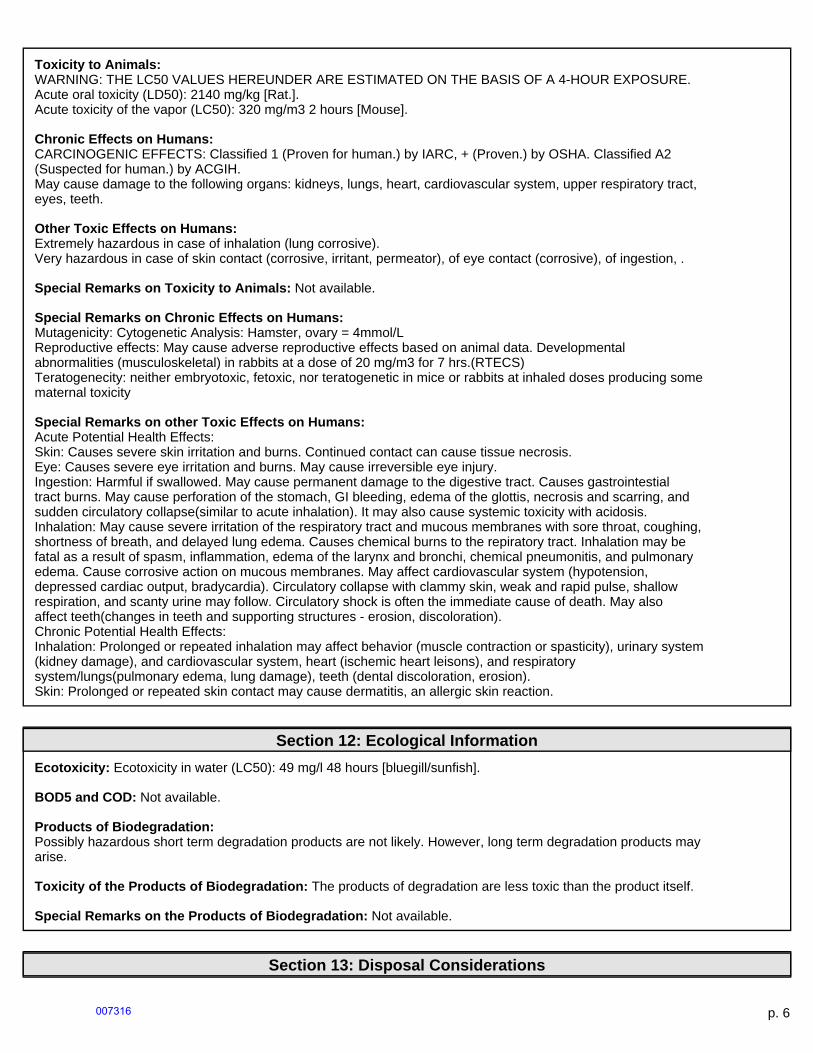
Toxicity to Animals:WARNING: THE LC50 VALUES HEREUNDER ARE ESTIMATED ON THE BASIS OF A 4-HOUR EXPOSURE.Acute oral toxicity (LD50): 2140 mg/kg [Rat.].Acute toxicity of the vapor (LC50): 320 mg/m3 2 hours [Mouse].
Chronic Effects on Humans:CARCINOGENIC EFFECTS: Classified 1 (Proven for human.) by IARC, + (Proven.) by OSHA. Classified A2(Suspected for human.) by ACGIH.May cause damage to the following organs: kidneys, lungs, heart, cardiovascular system, upper respiratory tract,eyes, teeth.
Other Toxic Effects on Humans:Extremely hazardous in case of inhalation (lung corrosive).Very hazardous in case of skin contact (corrosive, irritant, permeator), of eye contact (corrosive), of ingestion, .
Special Remarks on Toxicity to Animals: Not available.
Special Remarks on Chronic Effects on Humans:Mutagenicity: Cytogenetic Analysis: Hamster, ovary = 4mmol/LReproductive effects: May cause adverse reproductive effects based on animal data. Developmentalabnormalities (musculoskeletal) in rabbits at a dose of 20 mg/m3 for 7 hrs.(RTECS)Teratogenecity: neither embryotoxic, fetoxic, nor teratogenetic in mice or rabbits at inhaled doses producing somematernal toxicity
Special Remarks on other Toxic Effects on Humans:Acute Potential Health Effects:Skin: Causes severe skin irritation and burns. Continued contact can cause tissue necrosis.Eye: Causes severe eye irritation and burns. May cause irreversible eye injury.Ingestion: Harmful if swallowed. May cause permanent damage to the digestive tract. Causes gastrointestialtract burns. May cause perforation of the stomach, GI bleeding, edema of the glottis, necrosis and scarring, andsudden circulatory collapse(similar to acute inhalation). It may also cause systemic toxicity with acidosis.Inhalation: May cause severe irritation of the respiratory tract and mucous membranes with sore throat, coughing,shortness of breath, and delayed lung edema. Causes chemical burns to the repiratory tract. Inhalation may befatal as a result of spasm, inflammation, edema of the larynx and bronchi, chemical pneumonitis, and pulmonaryedema. Cause corrosive action on mucous membranes. May affect cardiovascular system (hypotension,depressed cardiac output, bradycardia). Circulatory collapse with clammy skin, weak and rapid pulse, shallowrespiration, and scanty urine may follow. Circulatory shock is often the immediate cause of death. May alsoaffect teeth(changes in teeth and supporting structures - erosion, discoloration).Chronic Potential Health Effects:Inhalation: Prolonged or repeated inhalation may affect behavior (muscle contraction or spasticity), urinary system(kidney damage), and cardiovascular system, heart (ischemic heart leisons), and respiratorysystem/lungs(pulmonary edema, lung damage), teeth (dental discoloration, erosion).Skin: Prolonged or repeated skin contact may cause dermatitis, an allergic skin reaction.
Section 12: Ecological Information
Ecotoxicity: Ecotoxicity in water (LC50): 49 mg/l 48 hours [bluegill/sunfish].
BOD5 and COD: Not available.
Products of Biodegradation:Possibly hazardous short term degradation products are not likely. However, long term degradation products mayarise.
Toxicity of the Products of Biodegradation: The products of degradation are less toxic than the product itself.
Special Remarks on the Products of Biodegradation: Not available.
Section 13: Disposal Considerations
p. 6007316

Waste Disposal:Sulfuric acid may be placed in sealed container or absorbed in vermiculite, dry sand, earth, or a similar material. Itmay also be diluted and neutralized. Be sure to consult with local or regional authorities (waste regulators) prior toany disposal. Waste must be disposed of in accordance with federal, state and local environmental controlregulations.
Section 14: Transport Information
DOT Classification: Class 8: Corrosive material
Identification: : Sulfuric acid UNNA: 1830 PG: II
Special Provisions for Transport: Not available.
Section 15: Other Regulatory Information
Federal and State Regulations:Illinois toxic substances disclosure to employee act: Sulfuric acidNew York release reporting list: Sulfuric acidRhode Island RTK hazardous substances: Sulfuric acidPennsylvania RTK: Sulfuric acidMinnesota: Sulfuric acidMassachusetts RTK: Sulfuric acidNew Jersey: Sulfuric acidCalifornia Director's List of Hazardous Substances (8 CCR 339): Sulfuric acidTennessee RTK: Sulfuric acidTSCA 8(b) inventory: Sulfuric acidSARA 302/304/311/312 extremely hazardous substances: Sulfuric acidSARA 313 toxic chemical notification and release reporting: Sulfuric acidCERCLA: Hazardous substances.: Sulfuric acid: 1000 lbs. (453.6 kg)
Other Regulations:OSHA: Hazardous by definition of Hazard Communication Standard (29 CFR 1910.1200).EINECS: This product is on the European Inventory of Existing Commercial Chemical Substances.
Other Classifications:
WHMIS (Canada):CLASS D-1A: Material causing immediate and serious toxic effects (VERY TOXIC).CLASS E: Corrosive liquid.
DSCL (EEC):R35- Causes severe burns.S2- Keep out of the reach of children.S26- In case of contact with eyes, rinseimmediately with plenty of water and seekmedical advice.S30- Never add water to this product.S45- In case of accident or if you feel unwell,seek medical advice immediately (show thelabel where possible).
HMIS (U.S.A.):
Health Hazard: 3
Fire Hazard: 0
Reactivity: 2
p. 7007317
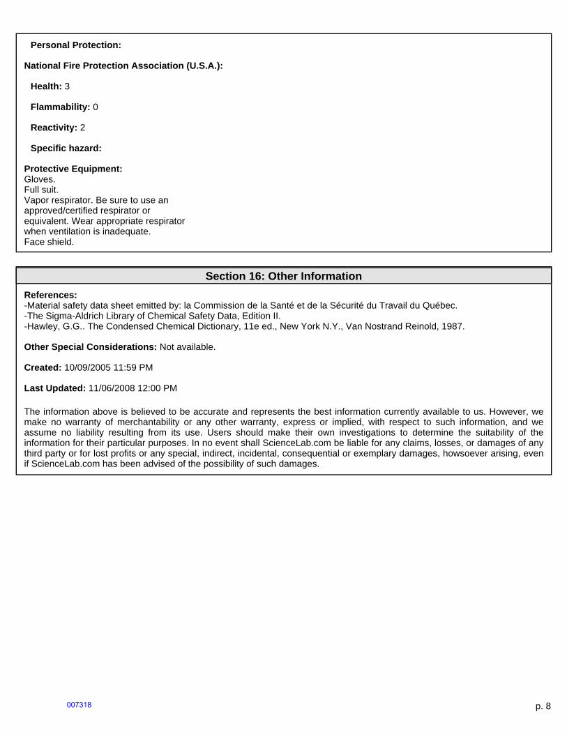
Personal Protection:
National Fire Protection Association (U.S.A.):
Health: 3
Flammability: 0
Reactivity: 2
Specific hazard:
Protective Equipment:Gloves.Full suit.Vapor respirator. Be sure to use anapproved/certified respirator orequivalent. Wear appropriate respiratorwhen ventilation is inadequate.Face shield.
Section 16: Other Information
References:-Material safety data sheet emitted by: la Commission de la Santé et de la Sécurité du Travail du Québec.-The Sigma-Aldrich Library of Chemical Safety Data, Edition II.-Hawley, G.G.. The Condensed Chemical Dictionary, 11e ed., New York N.Y., Van Nostrand Reinold, 1987.
Other Special Considerations: Not available.
Created: 10/09/2005 11:59 PM
Last Updated: 11/06/2008 12:00 PM
The information above is believed to be accurate and represents the best information currently available to us. However, wemake no warranty of merchantability or any other warranty, express or implied, with respect to such information, and weassume no liability resulting from its use. Users should make their own investigations to determine the suitability of theinformation for their particular purposes. In no event shall ScienceLab.com be liable for any claims, losses, or damages of anythird party or for lost profits or any special, indirect, incidental, consequential or exemplary damages, howsoever arising, evenif ScienceLab.com has been advised of the possibility of such damages.
p. 8007318

Material Safety Data SheetCalcium phosphate dibasic MSDS
Section 1: Chemical Product and Company Identification
Product Name: Calcium phosphate dibasic
Catalog Codes: SLC1030, SLC2821, SLC4609
CAS#: 7757-93-9
RTECS: Not available.
TSCA: TSCA 8(b) inventory: Calcium phosphate dibasic
CI#: Not available.
Synonym: Dicalcium Orthophosphate; Dicalciumphosphate; Calcium hydrogen orthophosphate CalciumHydrogen Phosphate; Calcium monohydrogen phosphaste
Chemical Name: Phosphoric acid, calcium salt (1:1)
Chemical Formula: CaHPO4
Contact Information:
Sciencelab.com, Inc.14025 Smith Rd.Houston, Texas 77396
US Sales: 1-800-901-7247International Sales: 1-281-441-4400
Order Online: ScienceLab.com
CHEMTREC (24HR Emergency Telephone), call:1-800-424-9300
International CHEMTREC, call: 1-703-527-3887
For non-emergency assistance, call: 1-281-441-4400
Section 2: Composition and Information on IngredientsComposition:
Name CAS # % by Weight
Calcium phosphate dibasic 7757-93-9 100
Toxicological Data on Ingredients: Calcium phosphate dibasic: ORAL (LD50): Acute: >10000 mg/kg [Rat]. DERMAL(LD50): Acute: >7940 mg/kg [Rabbit].
Section 3: Hazards Identification
Potential Acute Health Effects: Slightly hazardous in case of skin contact (irritant), of eye contact (irritant), of ingestion, ofinhalation.
Potential Chronic Health Effects:CARCINOGENIC EFFECTS: Not available.MUTAGENIC EFFECTS: Not available.TERATOGENIC EFFECTS: Not available.DEVELOPMENTAL TOXICITY: Not available.Repeated or prolonged exposure is not known to aggravate medical condition.
Section 4: First Aid Measures
p. 1007319
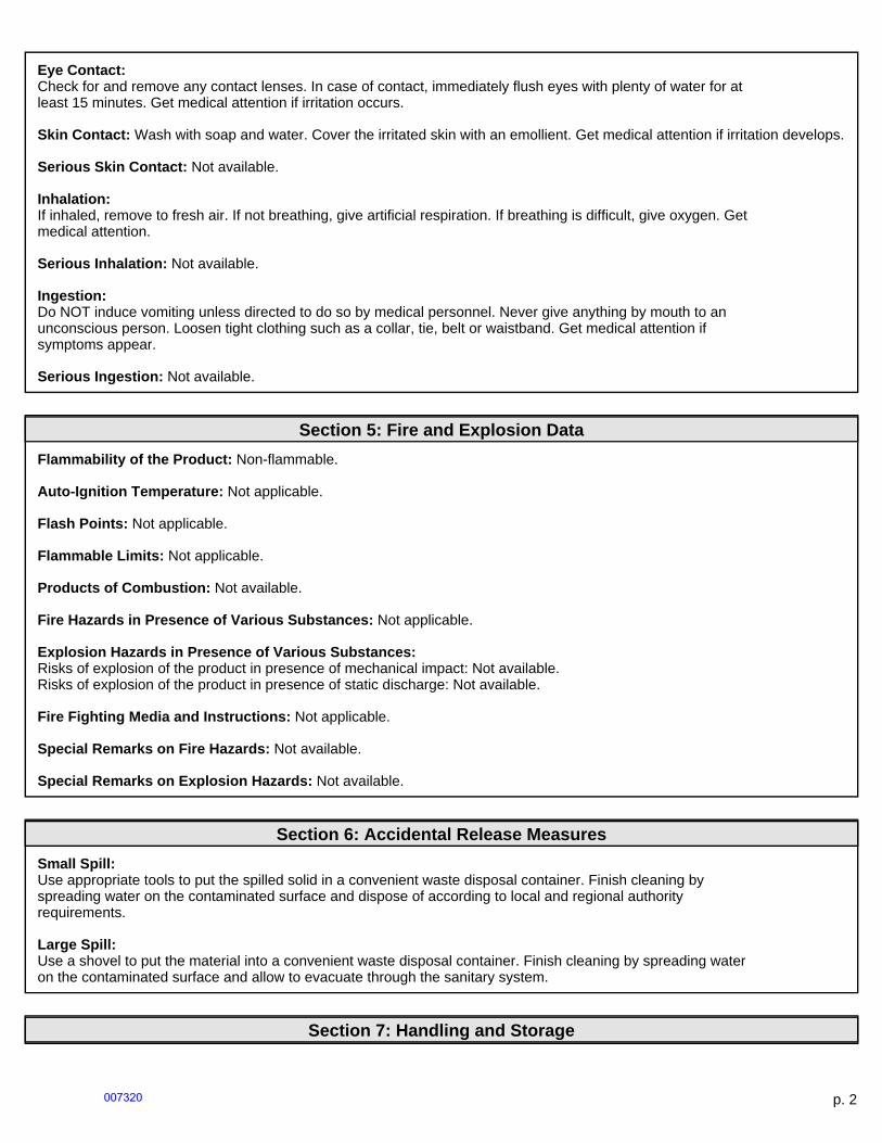
Eye Contact:Check for and remove any contact lenses. In case of contact, immediately flush eyes with plenty of water for atleast 15 minutes. Get medical attention if irritation occurs.
Skin Contact: Wash with soap and water. Cover the irritated skin with an emollient. Get medical attention if irritation develops.
Serious Skin Contact: Not available.
Inhalation:If inhaled, remove to fresh air. If not breathing, give artificial respiration. If breathing is difficult, give oxygen. Getmedical attention.
Serious Inhalation: Not available.
Ingestion:Do NOT induce vomiting unless directed to do so by medical personnel. Never give anything by mouth to anunconscious person. Loosen tight clothing such as a collar, tie, belt or waistband. Get medical attention ifsymptoms appear.
Serious Ingestion: Not available.
Section 5: Fire and Explosion Data
Flammability of the Product: Non-flammable.
Auto-Ignition Temperature: Not applicable.
Flash Points: Not applicable.
Flammable Limits: Not applicable.
Products of Combustion: Not available.
Fire Hazards in Presence of Various Substances: Not applicable.
Explosion Hazards in Presence of Various Substances:Risks of explosion of the product in presence of mechanical impact: Not available.Risks of explosion of the product in presence of static discharge: Not available.
Fire Fighting Media and Instructions: Not applicable.
Special Remarks on Fire Hazards: Not available.
Special Remarks on Explosion Hazards: Not available.
Section 6: Accidental Release Measures
Small Spill:Use appropriate tools to put the spilled solid in a convenient waste disposal container. Finish cleaning byspreading water on the contaminated surface and dispose of according to local and regional authorityrequirements.
Large Spill:Use a shovel to put the material into a convenient waste disposal container. Finish cleaning by spreading wateron the contaminated surface and allow to evacuate through the sanitary system.
Section 7: Handling and Storage
p. 2007320
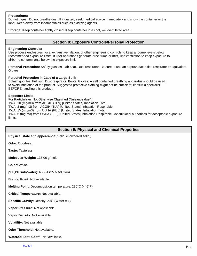
Precautions:Do not ingest. Do not breathe dust. If ingested, seek medical advice immediately and show the container or thelabel. Keep away from incompatibles such as oxidizing agents.
Storage: Keep container tightly closed. Keep container in a cool, well-ventilated area.
Section 8: Exposure Controls/Personal Protection
Engineering Controls:Use process enclosures, local exhaust ventilation, or other engineering controls to keep airborne levels belowrecommended exposure limits. If user operations generate dust, fume or mist, use ventilation to keep exposure toairborne contaminants below the exposure limit.
Personal Protection: Safety glasses. Lab coat. Dust respirator. Be sure to use an approved/certified respirator or equivalent.Gloves.
Personal Protection in Case of a Large Spill:Splash goggles. Full suit. Dust respirator. Boots. Gloves. A self contained breathing apparatus should be usedto avoid inhalation of the product. Suggested protective clothing might not be sufficient; consult a specialistBEFORE handling this product.
Exposure Limits:For Particlulates Not Otherwise Classified (Nuisance dust):TWA: 10 (mg/m3) from ACGIH (TLV) [United States] Inhalation Total.TWA: 3 (mg/m3) from ACGIH (TLV) [United States] Inhalation Respirable.TWA: 15 (mg/m3) from OSHA (PEL) [United States] Inhalation Total.TWA: 5 (mg/m3) from OSHA (PEL) [United States] Inhalation Respirable.Consult local authorities for acceptable exposurelimits.
Section 9: Physical and Chemical Properties
Physical state and appearance: Solid. (Powdered solid.)
Odor: Odorless.
Taste: Tasteless.
Molecular Weight: 136.06 g/mole
Color: White.
pH (1% soln/water): 6 - 7.4 (25% solution)
Boiling Point: Not available.
Melting Point: Decomposition temperature: 230°C (446°F)
Critical Temperature: Not available.
Specific Gravity: Density: 2.89 (Water = 1)
Vapor Pressure: Not applicable.
Vapor Density: Not available.
Volatility: Not available.
Odor Threshold: Not available.
Water/Oil Dist. Coeff.: Not available.
p. 3007321
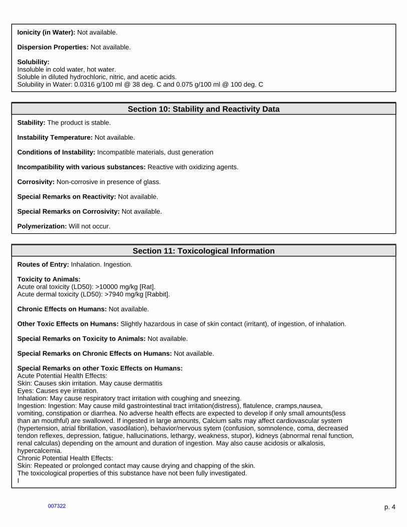
Ionicity (in Water): Not available.
Dispersion Properties: Not available.
Solubility:Insoluble in cold water, hot water.Soluble in diluted hydrochloric, nitric, and acetic acids.Solubility in Water: 0.0316 g/100 ml @ 38 deg. C and 0.075 g/100 ml @ 100 deg. C
Section 10: Stability and Reactivity Data
Stability: The product is stable.
Instability Temperature: Not available.
Conditions of Instability: Incompatible materials, dust generation
Incompatibility with various substances: Reactive with oxidizing agents.
Corrosivity: Non-corrosive in presence of glass.
Special Remarks on Reactivity: Not available.
Special Remarks on Corrosivity: Not available.
Polymerization: Will not occur.
Section 11: Toxicological Information
Routes of Entry: Inhalation. Ingestion.
Toxicity to Animals:Acute oral toxicity (LD50): >10000 mg/kg [Rat].Acute dermal toxicity (LD50): >7940 mg/kg [Rabbit].
Chronic Effects on Humans: Not available.
Other Toxic Effects on Humans: Slightly hazardous in case of skin contact (irritant), of ingestion, of inhalation.
Special Remarks on Toxicity to Animals: Not available.
Special Remarks on Chronic Effects on Humans: Not available.
Special Remarks on other Toxic Effects on Humans:Acute Potential Health Effects:Skin: Causes skin irritation. May cause dermatitisEyes: Causes eye irritation.Inhalation: May cause respiratory tract irritation with coughing and sneezing.Ingestion: Ingestion: May cause mild gastrointestinal tract irritation(distress), flatulence, cramps,nausea,vomiting, constipation or diarrhea. No adverse health effects are expected to develop if only small amounts(lessthan an mouthful) are swallowed. If ingested in large amounts, Calcium salts may affect cardiovascular system(hypertension, atrial fibrillation, vasodilation), behavior/nervous sytem (confusion, somnolence, coma, decreasedtendon reflexes, depression, fatigue, hallucinations, lethargy, weakness, stupor), kidneys (abnormal renal function,renal calculas) depending on the amount and duration of ingestion. May also cause acidosis or alkalosis,hypercalcemia.Chronic Potential Health Effects:Skin: Repeated or prolonged contact may cause drying and chapping of the skin.The toxicological properties of this substance have not been fully investigated.I
p. 4007322

Section 12: Ecological Information
Ecotoxicity: Ecotoxicity in water (LC50): >1000 mg/l 96 hours [Daphnia (daphnia)].
BOD5 and COD: Not available.
Products of Biodegradation:Possibly hazardous short term degradation products are not likely. However, long term degradation products mayarise.
Toxicity of the Products of Biodegradation: The product itself and its products of degradation are not toxic.
Special Remarks on the Products of Biodegradation: Not available.
Section 13: Disposal Considerations
Waste Disposal:Waste must be disposed of in accordance with federal, state and local environmentalcontrol regulations.
Section 14: Transport Information
DOT Classification: Not a DOT controlled material (United States).
Identification: Not applicable.
Special Provisions for Transport: Not applicable.
Section 15: Other Regulatory Information
Federal and State Regulations: TSCA 8(b) inventory: Calcium phosphate dibasic
Other Regulations: EINECS: This product is on the European Inventory of Existing Commercial Chemical Substances.
Other Classifications:
WHMIS (Canada): Not controlled under WHMIS (Canada).
DSCL (EEC):R36/38- Irritating to eyes and skin.S24/25- Avoid contact with skin and eyes.S26- In case of contact with eyes, rinseimmediately with plenty of water and seekmedical advice.S36- Wear suitable protective clothing.
HMIS (U.S.A.):
Health Hazard: 1
Fire Hazard: 0
Reactivity: 0
Personal Protection: E
National Fire Protection Association (U.S.A.):
Health: 1
p. 5007323
Flammability: 0
Reactivity: 0
Specific hazard:
Protective Equipment:Gloves.Lab coat.Dust respirator. Be sure to use anapproved/certified respirator orequivalent.Safety glasses.
Section 16: Other Information
References: Not available.
Other Special Considerations: Not available.
Created: 10/10/2005 08:16 PM
Last Updated: 10/10/2005 08:16 PM
The information above is believed to be accurate and represents the best information currently available to us. However, wemake no warranty of merchantability or any other warranty, express or implied, with respect to such information, and weassume no liability resulting from its use. Users should make their own investigations to determine the suitability of theinformation for their particular purposes. In no event shall ScienceLab.com be liable for any claims, losses, or damages of anythird party or for lost profits or any special, indirect, incidental, consequential or exemplary damages, howsoever arising, evenif ScienceLab.com has been advised of the possibility of such damages.
p. 6007324
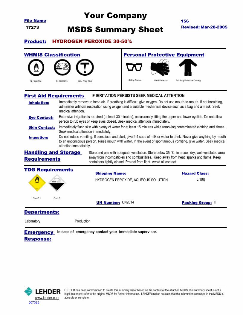
Revised: Mar-28-2005File Name
MSDS Summary Sheet17273156
Your Company
Product: HYDROGEN PEROXIDE 30-50%
IF IRRITATION PERSISTS SEEK MEDICAL ATTENTIONFirst Aid Requirements
Personal Protective EquipmentWHMIS Classification
C - Oxidizing E - Corrosive D2A - Very Toxic Safety Glasses Hand Protection Full Body Protective Clothing
Inhalation: Immediately remove to fresh air. If breathing is difficult, give oxygen. Do not use mouth-to-mouth. If not breathing, administer artificial respiration using oxygen and a suitable mechanical device such as a bag and a mask. Seek medical attention.
Eye Contact: Extensive irrigation is required (at least 30 minutes), occasionally lifting the upper and lower eyelids. Do not allow person to rub eyes or keep eyes closed. Seek medical attention immediately.
Skin Contact: Immediately flush skin with plenty of water for at least 15 minutes while removing contaminated clothing and shoes. Seek medical attention immediately.
Ingestion: Do not induce vomiting. If conscious and alert, give 2-4 cups of milk or water to drink. Never give anything by mouthto an unconscious person. Rinse mouth with water. In the event of spontaneous vomiting, give water. Seek medical attention immediately.
Handling and Storage Requirements
Store and use with adequate ventilation. Store below 35 °C in a cool, dry, well-ventilated area away from incompatibles and combustibles. Keep away from heat, sparks and flame. Keep containers tightly closed. Protect from light. Avoid all contact.
TDG Requirements
Packing Group:
Hazard Class:
UN Number:
Shipping Name:
Class 5.1 Class 8
HYDROGEN PEROXIDE, AQUEOUS SOLUTION
UN2014 II
5.1(8)
Departments:
Laboratory Production
Emergency Response:
In case of emergency contact your immediate supervisor.
LEHDER has been commisioned to create this summary sheet based on the content of the attached MSDS.This summary sheet is not a legal document; refer to the original MSDS for further information. LEHDER makes no claim that the information contained in the MSDS is accurate or complete.www.lehder.com
007325
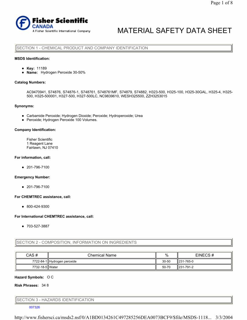
MSDS Identification:
Key: 11189 Name: Hydrogen Peroxide 30-50%
Catalog Numbers:
AC9470941, S74876, S74876-1, S748761, S748761MF, S74879, S74882, H323-500, H325-100, H325-30GAL, H325-4, H325-500, H325-500001, H327-500, H327-500LC, NC9839610, WESH325500, ZZH3253015
Synonyms:
Carbamide Peroxide; Hydrogen Dioxide; Peroxide; Hydroperoxide; Urea Peroxide; Hydrogen Peroxide 100 Volumes.
Company Identification:
Fisher Scientific 1 Reagent Lane Fairlawn, NJ 07410
For information, call:
201-796-7100
Emergency Number:
201-796-7100
For CHEMTREC assistance, call:
800-424-9300
For International CHEMTREC assistance, call:
703-527-3887
Hazard Symbols: O C Risk Phrases: 34 8
MATERIAL SAFETY DATA SHEET
SECTION 1 - CHEMICAL PRODUCT AND COMPANY IDENTIFICATION
SECTION 2 - COMPOSITION, INFORMATION ON INGREDIENTS
CAS # Chemical Name % EINECS # 7722-84-1 Hydrogen peroxide 30-50 231-765-0
7732-18-5 Water 50-70 231-791-2
SECTION 3 - HAZARDS IDENTIFICATION
Page 1 of 8
3/3/2004http://www.fishersci.ca/msds2.nsf/0/A1BD0134261C497285256DEA0073BCF9/$file/MSDS-1118...
007326
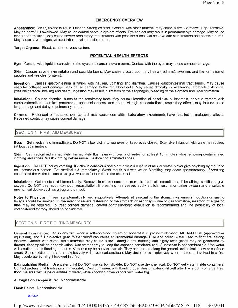
EMERGENCY OVERVIEW
Appearance: clear, colorless liquid. Danger! Strong oxidizer. Contact with other material may cause a fire. Corrosive. Light sensitive.May be harmful if swallowed. May cause central nervous system effects. Eye contact may result in permanent eye damage. May causeblood abnormalities. May cause severe respiratory tract irritation with possible burns. Causes eye and skin irritation and possible burns.May cause severe digestive tract irritation with possible burns. Target Organs: Blood, central nervous system.
POTENTIAL HEALTH EFFECTS Eye: Contact with liquid is corrosive to the eyes and causes severe burns. Contact with the eyes may cause corneal damage. Skin: Causes severe skin irritation and possible burns. May cause discoloration, erythema (redness), swelling, and the formation of papules and vesicles (blisters). Ingestion: Causes gastrointestinal irritation with nausea, vomiting and diarrhea. Causes gastrointestinal tract burns. May causevascular collapse and damage. May cause damage to the red blood cells. May cause difficulty in swallowing, stomach distension,possible cerebral swelling and death. Ingestion may result in irritation of the esophagus, bleeding of the stomach and ulcer formation. Inhalation: Causes chemical burns to the respiratory tract. May cause ulceration of nasal tissue, insomnia, nervous tremors withnumb extremities, chemical pneumonia, unconsciousness, and death. At high concentrations, respiratory effects may include acutelung damage and delayed pulmonary edema. Chronic: Prolonged or repeated skin contact may cause dermatitis. Laboratory experiments have resulted in mutagenic effects.Repeated contact may cause corneal damage.
Eyes: Get medical aid immediately. Do NOT allow victim to rub eyes or keep eyes closed. Extensive irrigation with water is required(at least 30 minutes). Skin: Get medical aid immediately. Immediately flush skin with plenty of water for at least 15 minutes while removing contaminated clothing and shoes. Wash clothing before reuse. Destroy contaminated shoes. Ingestion: Do NOT induce vomiting. If victim is conscious and alert, give 2-4 cupfuls of milk or water. Never give anything by mouth to an unconscious person. Get medical aid immediately. Wash mouth out with water. Vomiting may occur spontaneously. If vomitingoccurs and the victim is conscious, give water to further dilute the chemical. Inhalation: Get medical aid immediately. Remove from exposure and move to fresh air immediately. If breathing is difficult, giveoxygen. Do NOT use mouth-to-mouth resuscitation. If breathing has ceased apply artificial respiration using oxygen and a suitable mechanical device such as a bag and a mask. Notes to Physician: Treat symptomatically and supportively. Attempts at evacuating the stomach via emesis induction or gastriclavage should be avoided. In the event of severe distension of the stomach or esophagus due to gas formation, insertion of a gastrictube may be required. To treat corneal damage, careful ophthalmologic evaluation is recommended and the possibility of localcorticosteroid therapy should be considered.
General Information: As in any fire, wear a self-contained breathing apparatus in pressure-demand, MSHA/NIOSH (approved or equivalent), and full protective gear. Water runoff can cause environmental damage. Dike and collect water used to fight fire. Strongoxidizer. Contact with combustible materials may cause a fire. During a fire, irritating and highly toxic gases may be generated bythermal decomposition or combustion. Use water spray to keep fire-exposed containers cool. Substance is noncombustible. Use waterwith caution and in flooding amounts. Vapors may be heavier than air. They can spread along the ground and collect in low or confinedareas. Some oxidizers may react explosively with hydrocarbons(fuel). May decompose explosively when heated or involved in a fire.May accelerate burning if involved in a fire. Extinguishing Media: Use water only! Do NOT use carbon dioxide. Do NOT use dry chemical. Do NOT get water inside containers.Contact professional fire-fighters immediately. Cool containers with flooding quantities of water until well after fire is out. For large fires,flood fire area with large quantities of water, while knocking down vapors with water fog. Autoignition Temperature: Noncombustible Flash Point: Noncombustible
SECTION 4 - FIRST AID MEASURES
SECTION 5 - FIRE FIGHTING MEASURES
Page 2 of 8
3/3/2004http://www.fishersci.ca/msds2.nsf/0/A1BD0134261C497285256DEA0073BCF9/$file/MSDS-1118...
007327

Explosion Limits, lower: 40 vol % Explosion Limits, upper: 100 vol % NFPA Rating: (estimated) Health: 3; Flammability: 0; Instability: 1; Special Hazard: OX
General Information: Use proper personal protective equipment as indicated in Section 8. Spills/Leaks: Avoid runoff into storm sewers and ditches which lead to waterways. Clean up spills immediately, observing precautions in the Protective Equipment section. Use water spray to disperse the gas/vapor. Remove all sources of ignition. Absorb spill using anabsorbent, non-combustible material such as earth, sand, or vermiculite. Do not use combustible materials such as sawdust. Flush spill area with water. Provide ventilation. Do not get water inside containers. Keep combustibles (wood, paper, oil, etc.,) away from spilledmaterial.
Handling: Wash thoroughly after handling. Remove contaminated clothing and wash before reuse. Use only in a well-ventilated area. Contents may develop pressure upon prolonged storage. Do not get in eyes, on skin, or on clothing. Keep container tightly closed.Avoid contact with clothing and other combustible materials. Do not ingest or inhale. Store protected from light. Discard contaminatedshoes. Unused chemicals should not be returned to the container. Rinse empty drums and containers thoroughly with water beforediscarding. Storage: Keep away from heat, sparks, and flame. Do not store near combustible materials. Keep container closed when not in use.Store in a cool, dry, well-ventilated area away from incompatible substances. Store protected from light. Keep away form alkalies,oxidizable materials, finely divided metals, alcohols, and permanganates. Store below 35¦C. Store only in light-resistent containers fitted with a safety vent.
Engineering Controls: Use explosion-proof ventilation equipment. Facilities storing or utilizing this material should be equipped withan eyewash facility and a safety shower. Use adequate general or local exhaust ventilation to keep airborne concentrations below thepermissible exposure limits.
EXPOSURE LIMITS
OSHA Vacated PELs: Hydrogen peroxide: 1 ppm TWA; 1.4 mg/m3 TWA Water: No OSHA Vacated PELs are listed for this chemical.
PERSONAL PROTECTIVE EQUIPMENT Eyes: Wear appropriate protective eyeglasses or chemical safety goggles as described by OSHA's eye and face protectionregulations in 29 CFR 1910.133 or European Standard EN166. Skin: Wear appropriate protective gloves to prevent skin exposure. Clothing: Wear appropriate protective clothing to prevent skin exposure. Respirators: A respiratory protection program that meets OSHA's 29 CFR 1910.134 and ANSI Z88.2 requirements or EuropeanStandard EN 149 must be followed whenever workplace conditions warrant a respirator's use.
SECTION 6 - ACCIDENTAL RELEASE MEASURES
SECTION 7 - HANDLING AND STORAGE
SECTION 8 - EXPOSURE CONTROLS, PERSONAL PROTECTION
Chemical Name ACGIH NIOSH OSHA - Final PELs
Hydrogen peroxide 1 ppm 1 ppm TWA; 1.4mg/m3 TWA 75ppm IDLH 1 ppm TWA; 1.4mg/m3 TWA
Water none listed none listed none listed
Page 3 of 8
3/3/2004http://www.fishersci.ca/msds2.nsf/0/A1BD0134261C497285256DEA0073BCF9/$file/MSDS-1118...
007328
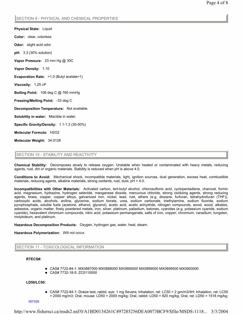
Physical State: Liquid Color: clear, colorless Odor: slight acid odor pH: 3.3 (30% solution) Vapor Pressure: 23 mm Hg @ 30C Vapor Density: 1.10 Evaporation Rate: >1.0 (Butyl acetate=1) Viscosity: 1.25 cP Boiling Point: 108 deg C @ 760 mmHg Freezing/Melting Point: -33 deg C Decomposition Temperature: Not available. Solubility in water: Miscible in water. Specific Gravity/Density: 1.1-1.2 (30-50%) Molecular Formula: H2O2 Molecular Weight: 34.0128
Chemical Stability: Decomposes slowly to release oxygen. Unstable when heated or contaminated with heavy metals, reducingagents, rust, dirt or organic materials. Stability is reduced when pH is above 4.0. Conditions to Avoid: Mechanical shock, incompatible materials, light, ignition sources, dust generation, excess heat, combustiblematerials, reducing agents, alkaline materials, strong oxidants, rust, dust, pH > 4.0. Incompatibilities with Other Materials: Activated carbon, tert-butyl alcohol, chlorosulfonic acid, cyclopentadiene, charcoal, formic acid, magnesium, hydrazine, hydrogen selenide, manganese dioxide, mercurous chloride, strong oxidizing agents, strong reducingagents, brass, copper, copper alloys, galvanized iron, nickel, lead, rust, ethers (e.g. dioxane, furfuran, tetrahydrofuran (THF)),carboxylic acids, alcohols, aniline, glycerine, sodium borate, urea, sodium carbonate, triethylamine, sodium fluoride, sodiumpyrophosphate, soluble fuels (acetone, ethanol, glycerol), acetic acid, acetic anhydride, nitrogen compounds, wood, wood, alkalies,asbestos, organic matter, finely powdered metals, iron, silver, platinum, palladium, ketones, cyanides (e.g. potassium cyanide, sodiumcyanide), hexavalent chromium compounds, nitric acid, potassium permanganate, salts of iron, copper, chromium, vanadium, tungsten,molybdeum, and platinum. Hazardous Decomposition Products: Oxygen, hydrogen gas, water, heat, steam. Hazardous Polymerization: Will not occur.
RTECS#:
CAS# 7722-84-1: MX0887000 MX0888000 MX0890000 MX0899000 MX0899500 MX0900000 CAS# 7732-18-5: ZC0110000
LD50/LC50:
CAS# 7722-84-1: Draize test, rabbit, eye: 1 mg Severe; Inhalation, rat: LC50 = 2 gm/m3/4H; Inhalation, rat: LC50 = 2000 mg/m3; Oral, mouse: LD50 = 2000 mg/kg; Oral, rabbit: LD50 = 820 mg/kg; Oral, rat: LD50 = 1518 mg/kg;
SECTION 9 - PHYSICAL AND CHEMICAL PROPERTIES
SECTION 10 - STABILITY AND REACTIVITY
SECTION 11 - TOXICOLOGICAL INFORMATION
Page 4 of 8
3/3/2004http://www.fishersci.ca/msds2.nsf/0/A1BD0134261C497285256DEA0073BCF9/$file/MSDS-1118...
007329
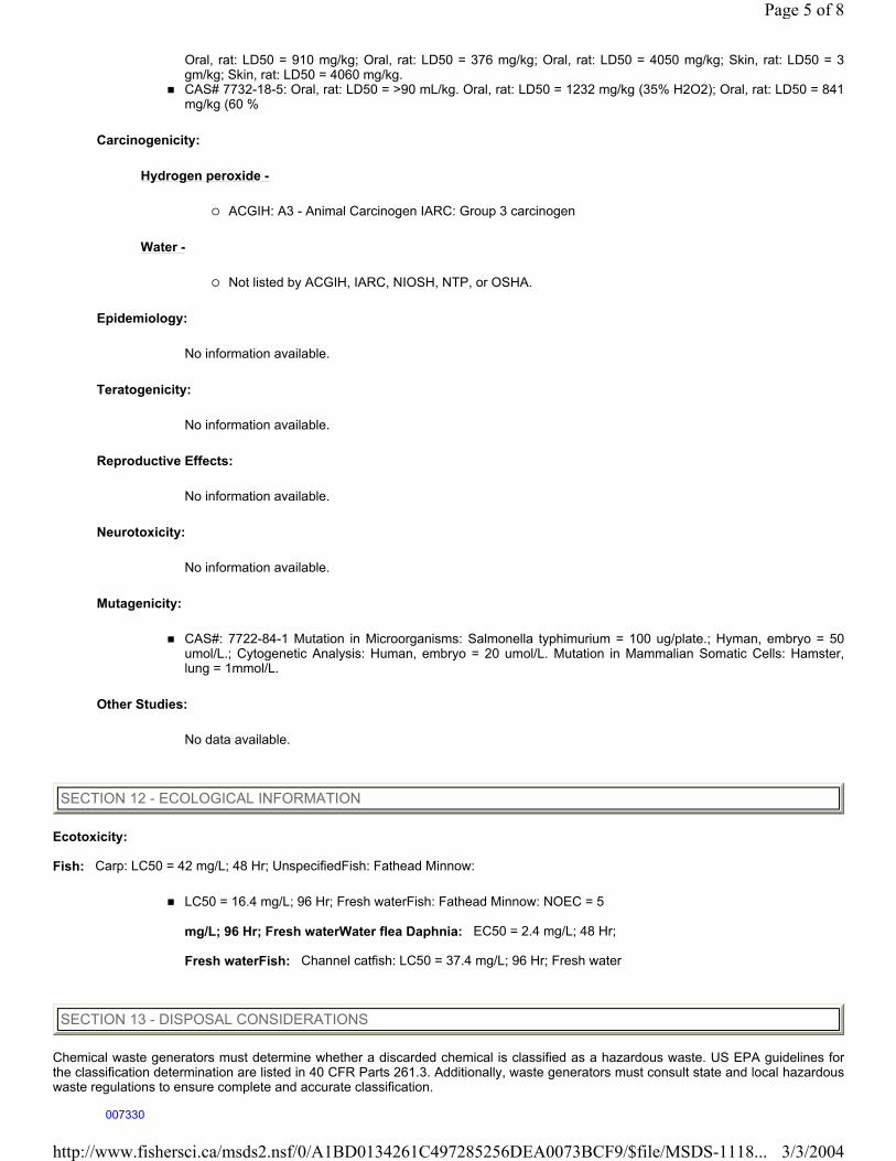
Oral, rat: LD50 = 910 mg/kg; Oral, rat: LD50 = 376 mg/kg; Oral, rat: LD50 = 4050 mg/kg; Skin, rat: LD50 = 3gm/kg; Skin, rat: LD50 = 4060 mg/kg. CAS# 7732-18-5: Oral, rat: LD50 = >90 mL/kg. Oral, rat: LD50 = 1232 mg/kg (35% H2O2); Oral, rat: LD50 = 841mg/kg (60 %
Carcinogenicity:
Hydrogen peroxide -
ACGIH: A3 - Animal Carcinogen IARC: Group 3 carcinogen
Water -
Not listed by ACGIH, IARC, NIOSH, NTP, or OSHA.
Epidemiology:
No information available.
Teratogenicity:
No information available.
Reproductive Effects:
No information available.
Neurotoxicity:
No information available.
Mutagenicity:
CAS#: 7722-84-1 Mutation in Microorganisms: Salmonella typhimurium = 100 ug/plate.; Hyman, embryo = 50umol/L.; Cytogenetic Analysis: Human, embryo = 20 umol/L. Mutation in Mammalian Somatic Cells: Hamster,lung = 1mmol/L.
Other Studies:
No data available.
Ecotoxicity: Fish: Carp: LC50 = 42 mg/L; 48 Hr; UnspecifiedFish: Fathead Minnow:
LC50 = 16.4 mg/L; 96 Hr; Fresh waterFish: Fathead Minnow: NOEC = 5 mg/L; 96 Hr; Fresh waterWater flea Daphnia: EC50 = 2.4 mg/L; 48 Hr; Fresh waterFish: Channel catfish: LC50 = 37.4 mg/L; 96 Hr; Fresh water
Chemical waste generators must determine whether a discarded chemical is classified as a hazardous waste. US EPA guidelines forthe classification determination are listed in 40 CFR Parts 261.3. Additionally, waste generators must consult state and local hazardouswaste regulations to ensure complete and accurate classification.
SECTION 12 - ECOLOGICAL INFORMATION
SECTION 13 - DISPOSAL CONSIDERATIONS
Page 5 of 8
3/3/2004http://www.fishersci.ca/msds2.nsf/0/A1BD0134261C497285256DEA0073BCF9/$file/MSDS-1118...
007330
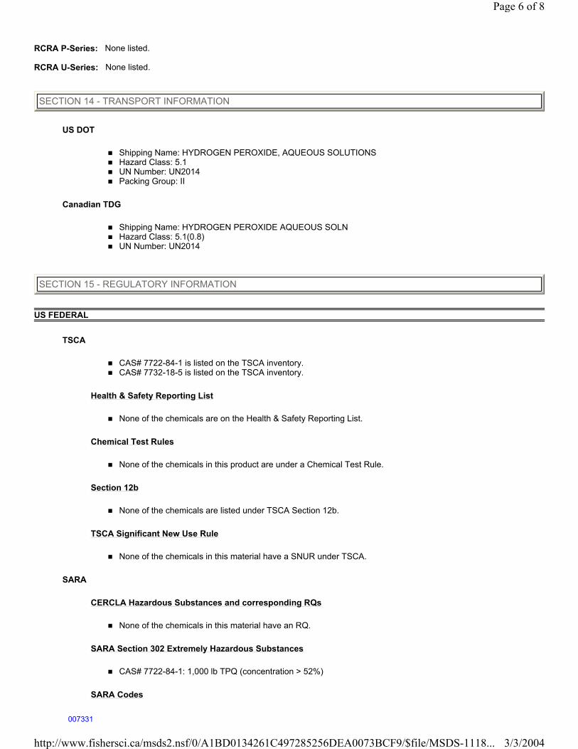
RCRA P-Series: None listed. RCRA U-Series: None listed.
US DOT
Shipping Name: HYDROGEN PEROXIDE, AQUEOUS SOLUTIONS Hazard Class: 5.1 UN Number: UN2014 Packing Group: II
Canadian TDG
Shipping Name: HYDROGEN PEROXIDE AQUEOUS SOLN Hazard Class: 5.1(0.8) UN Number: UN2014
US FEDERAL
TSCA
CAS# 7722-84-1 is listed on the TSCA inventory. CAS# 7732-18-5 is listed on the TSCA inventory.
Health & Safety Reporting List
None of the chemicals are on the Health & Safety Reporting List.
Chemical Test Rules
None of the chemicals in this product are under a Chemical Test Rule.
Section 12b
None of the chemicals are listed under TSCA Section 12b.
TSCA Significant New Use Rule
None of the chemicals in this material have a SNUR under TSCA.
SARA
CERCLA Hazardous Substances and corresponding RQs
None of the chemicals in this material have an RQ.
SARA Section 302 Extremely Hazardous Substances
CAS# 7722-84-1: 1,000 lb TPQ (concentration > 52%)
SARA Codes
SECTION 14 - TRANSPORT INFORMATION
SECTION 15 - REGULATORY INFORMATION
Page 6 of 8
3/3/2004http://www.fishersci.ca/msds2.nsf/0/A1BD0134261C497285256DEA0073BCF9/$file/MSDS-1118...
007331
CAS # 7722-84-1: acute, flammable.
Section 313
No chemicals are reportable under Section 313.
Clean Air Act:
This material does not contain any hazardous air pollutants. This material does not contain any Class 1 Ozone depletors. This material does not contain any Class 2 Ozone depletors.
Clean Water Act:
None of the chemicals in this product are listed as Hazardous Substances under the CWA. None of the chemicals in this product are listed as Priority Pollutants under the CWA. None of the chemicals in this product are listed as Toxic Pollutants under the CWA.
OSHA:
None of the chemicals in this product are considered highly hazardous by OSHA.
STATE
Hydrogen peroxide can be found on the following state right to know lists: California, New Jersey, Pennsylvania, Minnesota, Massachusetts. Water is not present on state lists from CA, PA, MN, MA, FL, or NJ. California No Significant Risk Level: None of the chemicals in this product are listed.
European/International Regulations
European Labeling in Accordance with EC Directives
Hazard Symbols: O C Risk Phrases:
R 34 Causes burns. R 8 Contact with combustible material may cause fire.
Safety Phrases:
S 3 Keep in a cool place. S 28 After contact with skin, wash immediately with... S 36/39 Wear suitable protective clothing and eye/face protection. S 45 In case of accident or if you feel unwell, seek medical advice immediately (show the label where possible).
WGK (Water Danger/Protection)
CAS# 7722-84-1: 0 CAS# 7732-18-5: No information available.
United Kingdom Occupational Exposure Limits
CAS# 7722-84-1: OES-United Kingdom, TWA 1 ppm TWA; 1.4 mg/m3 TWA CAS# 7722-84-1: OES-United Kingdom, STEL 2 ppm STEL; 2.8 mg/m3 STEL CAS# 7722-84-1: OES-United Kingdom, STEL 2 ppm STEL; 2.8 mg/m3 STEL
United Kingdom Maximum Exposure Limits
Page 7 of 8
3/3/2004http://www.fishersci.ca/msds2.nsf/0/A1BD0134261C497285256DEA0073BCF9/$file/MSDS-1118...
007332

Canada
CAS# 7722-84-1 is listed on Canada's DSL List. CAS# 7732-18-5 is listed on Canada's DSL List. This product has a WHMIS classification of C, E, D2A. CAS# 7722-84-1 is listed on Canada's Ingredient Disclosure List. CAS# 7732-18-5 is not listed on Canada's Ingredient Disclosure List.
Exposure Limits
CAS# 7722-84-1: OEL-AUSTRALIA:TWA 1 ppm (1.5 mg/m3) OEL-BELGIUM:TWA 1 ppm (1.4 mg/m3) OEL-DENMARK:TWA 1 ppm (1.4 mg/m3) OEL-FINLAND:TWA 1 ppm (1.4 mg/m3);STEL 3 ppm (4.2 mg/m3) OEL-FRANCE:TWA 1 ppm (1.5 mg/m3) OEL-GERMANY:TWA 1 ppm (1.4 mg/m3) OEL-THE NETHERLANDS:TWA 1 ppm (1.4 mg/m3) OEL-THE PHILIPPINES:TWA 1 ppm (1.4 mg/m3) OEL-SWITZERLAND:TWA 1 ppm (1.4 mg/m3);STEL 2 ppm (2.8 mg/m3) OEL-TURKEY:TWA 1 ppm (1.4 mg/m3) OEL-UNITED KINGDOM:TWA 1 ppm (1.5 mg/m3);STEL 2 ppm (3 mg/m3)
MSDS Creation Date: 4/21/1999, Revision #4 Date: 3/18/2003 The information above is believed to be accurate and represents the best information currently available to us. However, we make nowarranty of merchantability or any other warranty, express or implied, with respect to such information, and we assume no liabilityresulting from its use. Users should make their own investigations to determine the suitability of the information for their particularpurposes. In no way shall the company be liable for any claims, losses, or damages of any third party or for lost profits or any special,indirect, incidental, consequential or exemplary damages, howsoever arising, even if the company has been advised of the possibility ofsuch damages.
SECTION 16 - ADDITIONAL INFORMATION
Page 8 of 8
3/3/2004http://www.fishersci.ca/msds2.nsf/0/A1BD0134261C497285256DEA0073BCF9/$file/MSDS-1118...
007333
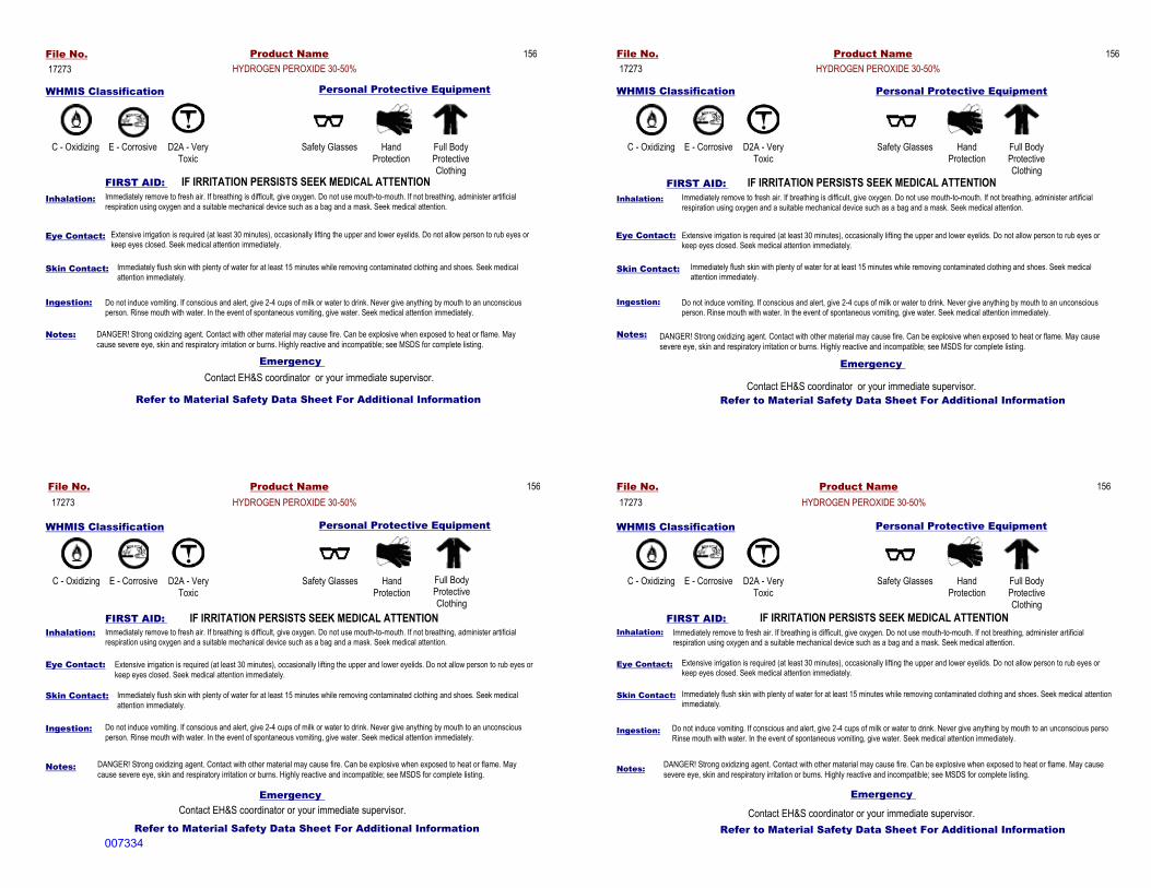
WHMIS Classification Personal Protective Equipment
FIRST AID: IF IRRITATION PERSISTS SEEK MEDICAL ATTENTION
Product NameFile No.
WHMIS Classification Personal Protective Equipment
IF IRRITATION PERSISTS SEEK MEDICAL ATTENTIONFIRST AID:
Eye Contact:Eye Contact:
Ingestion:Ingestion:
Eye Contact:
FIRST AID: IF IRRITATION PERSISTS SEEK MEDICAL ATTENTION
Ingestion:
Eye Contact:
Emergency
Refer to Material Safety Data Sheet For Additional Information
Emergency
Refer to Material Safety Data Sheet For Additional Information
Skin Contact:
Ingestion:
Notes: Notes:
Inhalation:
Skin Contact:
Refer to Material Safety Data Sheet For Additional Information
Emergency
Contact EH&S coordinator or your immediate supervisor.Refer to Material Safety Data Sheet For Additional Information
Emergency Contact EH&S coordinator or your immediate supervisor.
IF IRRITATION PERSISTS SEEK MEDICAL ATTENTIONFIRST AID:
Personal Protective EquipmentWHMIS ClassificationPersonal Protective EquipmentWHMIS Classification
Inhalation:
Notes:Notes:
Skin Contact:Skin Contact:
Inhalation:Inhalation:
Contact EH&S coordinator or your immediate supervisor.Contact EH&S coordinator or your immediate supervisor.
HYDROGEN PEROXIDE 30-50%17273
C - Oxidizing E - Corrosive D2A - Very Toxic
Safety Glasses Hand Protection
Full Body Protective Clothing
Immediately remove to fresh air. If breathing is difficult, give oxygen. Do not use mouth-to-mouth. If not breathing, administer artificial respiration using oxygen and a suitable mechanical device such as a bag and a mask. Seek medical attention.
Extensive irrigation is required (at least 30 minutes), occasionally lifting the upper and lower eyelids. Do not allow person to rub eyes or keep eyes closed. Seek medical attention immediately.
Immediately flush skin with plenty of water for at least 15 minutes while removing contaminated clothing and shoes. Seek medical attention immediately.
Do not induce vomiting. If conscious and alert, give 2-4 cups of milk or water to drink. Never give anything by mouth to an unconscious person. Rinse mouth with water. In the event of spontaneous vomiting, give water. Seek medical attention immediately.
DANGER! Strong oxidizing agent. Contact with other material may cause fire. Can be explosive when exposed to heat or flame. May cause severe eye, skin and respiratory irritation or burns. Highly reactive and incompatible; see MSDS for complete listing.
C - Oxidizing E - Corrosive D2A - Very Toxic
Safety Glasses Hand Protection
Full Body Protective Clothing
C - Oxidizing Safety GlassesE - Corrosive D2A - Very Toxic
Hand Protection
Full Body Protective Clothing
Immediately remove to fresh air. If breathing is difficult, give oxygen. Do not use mouth-to-mouth. If not breathing, administer artificial respiration using oxygen and a suitable mechanical device such as a bag and a mask. Seek medical attention.
Extensive irrigation is required (at least 30 minutes), occasionally lifting the upper and lower eyelids. Do not allow person to rub eyes or keep eyes closed. Seek medical attention immediately.
Immediately flush skin with plenty of water for at least 15 minutes while removing contaminated clothing and shoes. Seek medical attention immediately.
Do not induce vomiting. If conscious and alert, give 2-4 cups of milk or water to drink. Never give anything by mouth to an unconscious person. Rinse mouth with water. In the event of spontaneous vomiting, give water. Seek medical attention immediately.
DANGER! Strong oxidizing agent. Contact with other material may cause fire. Can be explosive when exposed to heat or flame. May cause severe eye, skin and respiratory irritation or burns. Highly reactive and incompatible; see MSDS for complete listing.
Immediately remove to fresh air. If breathing is difficult, give oxygen. Do not use mouth-to-mouth. If not breathing, administer artificial respiration using oxygen and a suitable mechanical device such as a bag and a mask. Seek medical attention.
Extensive irrigation is required (at least 30 minutes), occasionally lifting the upper and lower eyelids. Do not allow person to rub eyes or keep eyes closed. Seek medical attention immediately.
Immediately flush skin with plenty of water for at least 15 minutes while removing contaminated clothing and shoes. Seek medical attention immediately.
Do not induce vomiting. If conscious and alert, give 2-4 cups of milk or water to drink. Never give anything by mouth to an unconscious personRinse mouth with water. In the event of spontaneous vomiting, give water. Seek medical attention immediately.
DANGER! Strong oxidizing agent. Contact with other material may cause fire. Can be explosive when exposed to heat or flame. May cause severe eye, skin and respiratory irritation or burns. Highly reactive and incompatible; see MSDS for complete listing.
156
17273Product NameFile No.
HYDROGEN PEROXIDE 30-50%156 File No.
17273Product Name
HYDROGEN PEROXIDE 30-50%156
17273Product NameFile No.
HYDROGEN PEROXIDE 30-50%156
007334

ATTACHMENTS
2010 ES TT STUDY HSP ADDENDUM AMERICAN CREOSOTE.DOC OCTOBER 2010 ES101410012121DFW\102870012
(This page intentionally left blank)
007335

2010 ES TT STUDY HSP ADDENDUM AMERICAN CREOSOTE.DOC A-7 OCTOBER 2010 ES101410012121DFW\102870012
ATTACHMENT 7
Working Alone Standard
See the HSP American Creosote Works (CH2M HILL, 2010).
007336

2010 ES TT STUDY HSP ADDENDUM AMERICAN CREOSOTE.DOC A-8 OCTOBER 2010 ES101410012121DFW\102870012
ATTACHMENT 8
Tick Fact Sheet
See the HSP American Creosote Works (CH2M HILL, 2010).
007337

2010 ES TT STUDY HSP ADDENDUM AMERICAN CREOSOTE.DOC A-9 OCTOBER 2010 ES101410012121DFW\102870012
ATTACHMENT 9
Observed Hazard Form
See the HSP American Creosote Works (CH2M HILL, 2010).
007338

ATTACHMENTS
2010 ES TT STUDY HSP ADDENDUM AMERICAN CREOSOTE.DOC OCTOBER 2010 ES101410012121DFW\102870012
(This page intentionally left blank)
007339

Appendix B Soil and Groundwater Sampling Procedures
007340

APPENDIX B: SOIL AND GROUNDWATER SAMPLING PROCEDURES
ACW_TTP_VER2.1.DOCX NOVEMBER 2011 ES111011092113DFW
(This page intentionally left blank)
007341
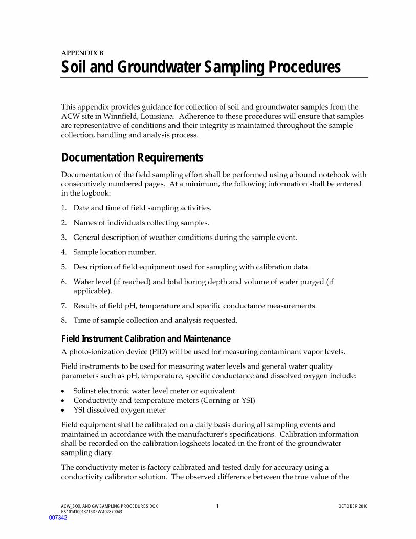
ACW_SOIL AND GW SAMPLING PROCEDURES.DOX 1 OCTOBER 2010 ES101410013716DFW\102870043
APPENDIX B
Soil and Groundwater Sampling Procedures
This appendix provides guidance for collection of soil and groundwater samples from the ACW site in Winnfield, Louisiana. Adherence to these procedures will ensure that samples are representative of conditions and their integrity is maintained throughout the sample collection, handling and analysis process.
Documentation Requirements Documentation of the field sampling effort shall be performed using a bound notebook with consecutively numbered pages. At a minimum, the following information shall be entered in the logbook:
1. Date and time of field sampling activities.
2. Names of individuals collecting samples.
3. General description of weather conditions during the sample event.
4. Sample location number.
5. Description of field equipment used for sampling with calibration data.
6. Water level (if reached) and total boring depth and volume of water purged (if applicable).
7. Results of field pH, temperature and specific conductance measurements.
8. Time of sample collection and analysis requested.
Field Instrument Calibration and Maintenance A photo-ionization device (PID) will be used for measuring contaminant vapor levels.
Field instruments to be used for measuring water levels and general water quality parameters such as pH, temperature, specific conductance and dissolved oxygen include:
• Solinst electronic water level meter or equivalent • Conductivity and temperature meters (Corning or YSI) • YSI dissolved oxygen meter
Field equipment shall be calibrated on a daily basis during all sampling events and maintained in accordance with the manufacturer's specifications. Calibration information shall be recorded on the calibration logsheets located in the front of the groundwater sampling diary.
The conductivity meter is factory calibrated and tested daily for accuracy using a conductivity calibrator solution. The observed difference between the true value of the
007342

AMERICAN CREOSOTE WORKS SITE, FEASIBILITY STUDY SOIL AND GROUNDWATER SAMPLING PROCEDURES
ACW_SOIL AND GW SAMPLING PROCEDURES.DOX 2 OCTOBER 2010 ES101410013716DFW\102870043
calibrator solution and the value measured by meter is the correction factor. Prior to performing this test the Red Line/Battery check test is performed by following the instructions on the face of the meter. When recording the calibrator solution conductivity measurement, make sure the temperature is also recorded in the field logbook.
The YSI dissolved oxygen meter is calibrated to the ambient atmospheric concentration adjusted for elevation and temperature. The YSI pH meter is calibrated daily using a manual or auto-calibration method requiring two buffer solutions: pH 7.0 and either pH 4.0 or pH 10.0. The buffers used depend on the range of pH expected in sampled groundwater or surface water.
The electronic water level indicator is tested for operability on a daily basis using the self-test function on the meter.
Field equipment model and identification numbers are also recorded with calibration measurements in the field notebook to document instrument deviations, which may occur between different model types.
Laboratory Analysis Samples shall be shipped at least every two days via overnight carrier to the subcontract laboratory. Samples held overnight prior to shipment shall be maintained in a refrigerator or iced cooler at a temperate of 2 to 4 degrees Celsius. Additional laboratory related information is provided in the Field Operations Plan (FOP) (CH2M HILL, 2006) Appendix D.
Sample Custody The chain-of-custody program is a means to trace the possession and handling of individual samples from the time of field collection through laboratory analysis. The chain-of-custody program includes:
• Sample labels • Chain-of-custody forms • Chain-of-custody seals • Sample packaging and shipment • Laboratory notebook and report
The chain-of-custody program described in this report is for the field aspects only. Laboratory chain-of-custody and control are mandatory for any laboratories performing environmental testing. Laboratory custody procedures are described in the subcontract laboratoy's Quality Assurance Program Manual.
Sample Labels A sample label will be affixed to each sample bottle before sample collection. The information contained on each label will include the following:
• Site description
007343

AMERICAN CREOSOTE WORKS SITE, FEASIBILITY STUDY SOIL AND GROUNDWATER SAMPLING PROCEDURES
ACW_SOIL AND GW SAMPLING PROCEDURES.DOX 3 OCTOBER 2010 ES101410013716DFW\102870043
• Sample location • Date and time sampled • Name of sample collector • Preservative type
The sample number will be determined by a coding system identifying the project site, a sample location, and date. An example may be:
ACW-MW3s-0104
Where: ACW = American Creosote Works site
MW3 = Monitor well 3.
0104 = year and month of sampling.
To maintain the integrity of field quality assurance samples, field duplicate, equipment blank, and trip blank samples shall be labeled with fictitious monitor well numbers so that their identity will not be evident to the laboratory. Samples shall be labeled using the following format:
Field Duplicate Sample = ACW-MWDD-0104
Where: DD = well number between 20 and 30
Equipment Blanks = BS-MWBBa-0104
Where: BB = well number between 31 and 40
Trip Blanks = BS-MWTT-0104
Where: TT = well number between 41 and 50
When collecting quality assurance and quality control samples, careful documentation shall be maintained in the field logbook so that the origin of the sample can be traced.
Field Logbook The sample team shall maintain a logbook for pilot testing activities. This logbook will be a bound notebook with numbered pages. At the start of each day the names of sample team members, weather conditions, and reason for sampling will be recorded. The Site Monitoring Officer will maintain custody of the field logbook at all times.
Data obtained on groundwater samples will be entered into the logbook and may include: the well identification, well depth, static water level depth and measurement technique, water turbidity (estimate) and color, water odor (if present), well yield including changes in pump performance, sample identification numbers, well evacuation procedure and equipment, sample withdrawal procedure and equipment, date and time of collection, well sampling sequence, types of sampling containers and preservative(s) used, parameters requested for analysis, field measurement and calibration data, analysis data and methods,
007344
AMERICAN CREOSOTE WORKS SITE, FEASIBILITY STUDY SOIL AND GROUNDWATER SAMPLING PROCEDURES
ACW_SOIL AND GW SAMPLING PROCEDURES.DOX 4 OCTOBER 2010 ES101410013716DFW\102870043
sample distribution and transporter, field observations on sampling event, and name of collector.
All log book entries will be made with nonerasable ink. Any corrections will be made by striking out the incorrect entry with a single line such that the original entry is not obliterated. The person making the correction will also initial and date the crossed out entry. The correct entry will then be made above the crossed-out entry.
Chain-of-Custody Custody of a sample is defined by the following criteria:
1. The sample is in your possession or in your view after being in your possession.
2. The sample that was in your possession was locked up or transferred to a designated secure area by you.
Each time the sample containers change hands, both the sender and receiver will sign and date the chain-of-custody form and specify what has changed hands. When a sample shipment is sent to the laboratory, the top signature copies are enclosed in plastic with the sample documentation and secured to the inside of the sample cooler lid. The third copy of the custody form will be retained in the project file. The laboratory will be instructed to sign its copy of the chain-of-custody sheet included with the samples and return a copy of the signed sheet along with the analytical results. A chain-of-custody record will be completed for each shipping container.
The following information is included on the chain-of-custody form:
• Sample number • Signature of sampler • Date and time of collection • Place of collection • Type of sample • Number and type of container • Inclusive dates of possession • Signature of receiver
In addition to the chain-of-custody form, other components of chain-of-custody control may include sample labels, sample seals, field logbook, and the laboratory logbook. The chain-of-custody form includes all elements of a sample analysis request sheet.
Chain-of-Custody Seals Chain-of-custody seals will be placed on individual coolers at any time the cooler is not in view of the sample team or is stored in an unsecured area. The team will sign and date the chain-of-custody seals and attach them in such a way that is necessary to break the seal in order to open the sample cooler. At least two chain-of-custody seals are attached to the sample cooler, one each on the front and back. Fiber tape may also be placed at each end of the custody seal for additional security.
007345

AMERICAN CREOSOTE WORKS SITE, FEASIBILITY STUDY SOIL AND GROUNDWATER SAMPLING PROCEDURES
ACW_SOIL AND GW SAMPLING PROCEDURES.DOX 5 OCTOBER 2010 ES101410013716DFW\102870043
Laboratory Logbook Once the sample has been received in the laboratory, the sample custodian or laboratory personnel will clearly document the processing steps that are applied to the sample. The results of the analysis of all quality-control samples will be identified specific to each batch of groundwater samples analyzed. The laboratory logbook will include the time, date, and name of the person who performed each processing step.
Sample Packaging and Shipment Packaging and shipment of samples to non-local laboratories should follow these guidelines:
1. Sample volume should be limited to the quantity necessary to conduct the requisite analysis and the smallest appropriate container should be used.
2. Samples, for which EPA approved analytical methods require preservation at 4 o C, shall be preserved by placing the sample containers in sturdy coolers filled with ice placed in double bagged one-gallon ziploc bags. Four to six bags of ice shall be placed in each cooler.
3. Shipping containers-All sample containers are to be placed inside a strong outside shipping container. A metal or plastic picnic cooler (ice chest) lined inside with hard plastic complies with the DOT drop test requirement. The container should also be taped shut to achieve as tight a seal as possible around the lid to prevent leakage should the container be accidentally turned over.
4. Glass containers-The container's screw-type lid must be tightened before it is placed in the shipping container. In the shipping container glass bottles should be separated by cushioning or absorbent material (e.g., Styrofoam, blotting paper or newspaper) to prevent contact with other hard objects and prevent breakage. For example, a 1-gallon glass bottle (organic sample) can be placed between two carved out Styrofoam sheets, which secure the bottle at the top and bottom. Small glass bottles (volatile organic samples) can be placed inside a foam cushion vial container to minimize breakage.
5. Plastic containers-Polyethylene bottles or cubit containers do not require cushioning materials to prevent breakage but do need to be protected from puncture by sharp objects. Caps are to be tightly screwed on before the plastic containers are placed in the shipping container.
6. Ice can be placed in separate sealed double plastic bags, or in large-mouthed plastic cubit containers with screwtype lids. Packing material such as bubble wrap or Styrofoam may be added to "top off" the cooler contents.
7. Place a copy of the chain-of-custody inside a plastic bag and secure it to the top of the shipping container lid form before closing and sealing.
8. Secure the cooler lid with several wrappings of fiber tape.
007346
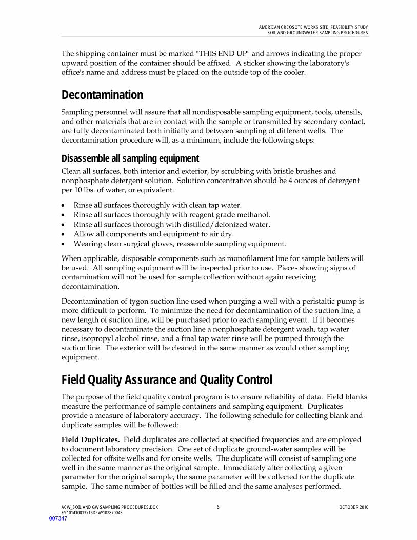
AMERICAN CREOSOTE WORKS SITE, FEASIBILITY STUDY SOIL AND GROUNDWATER SAMPLING PROCEDURES
ACW_SOIL AND GW SAMPLING PROCEDURES.DOX 6 OCTOBER 2010 ES101410013716DFW\102870043
The shipping container must be marked "THIS END UP" and arrows indicating the proper upward position of the container should be affixed. A sticker showing the laboratory's office's name and address must be placed on the outside top of the cooler.
Decontamination Sampling personnel will assure that all nondisposable sampling equipment, tools, utensils, and other materials that are in contact with the sample or transmitted by secondary contact, are fully decontaminated both initially and between sampling of different wells. The decontamination procedure will, as a minimum, include the following steps:
Disassemble all sampling equipment Clean all surfaces, both interior and exterior, by scrubbing with bristle brushes and nonphosphate detergent solution. Solution concentration should be 4 ounces of detergent per 10 lbs. of water, or equivalent.
• Rinse all surfaces thoroughly with clean tap water. • Rinse all surfaces thoroughly with reagent grade methanol. • Rinse all surfaces thorough with distilled/deionized water. • Allow all components and equipment to air dry. • Wearing clean surgical gloves, reassemble sampling equipment.
When applicable, disposable components such as monofilament line for sample bailers will be used. All sampling equipment will be inspected prior to use. Pieces showing signs of contamination will not be used for sample collection without again receiving decontamination.
Decontamination of tygon suction line used when purging a well with a peristaltic pump is more difficult to perform. To minimize the need for decontamination of the suction line, a new length of suction line, will be purchased prior to each sampling event. If it becomes necessary to decontaminate the suction line a nonphosphate detergent wash, tap water rinse, isopropyl alcohol rinse, and a final tap water rinse will be pumped through the suction line. The exterior will be cleaned in the same manner as would other sampling equipment.
Field Quality Assurance and Quality Control The purpose of the field quality control program is to ensure reliability of data. Field blanks measure the performance of sample containers and sampling equipment. Duplicates provide a measure of laboratory accuracy. The following schedule for collecting blank and duplicate samples will be followed:
Field Duplicates. Field duplicates are collected at specified frequencies and are employed to document laboratory precision. One set of duplicate ground-water samples will be collected for offsite wells and for onsite wells. The duplicate will consist of sampling one well in the same manner as the original sample. Immediately after collecting a given parameter for the original sample, the same parameter will be collected for the duplicate sample. The same number of bottles will be filled and the same analyses performed.
007347
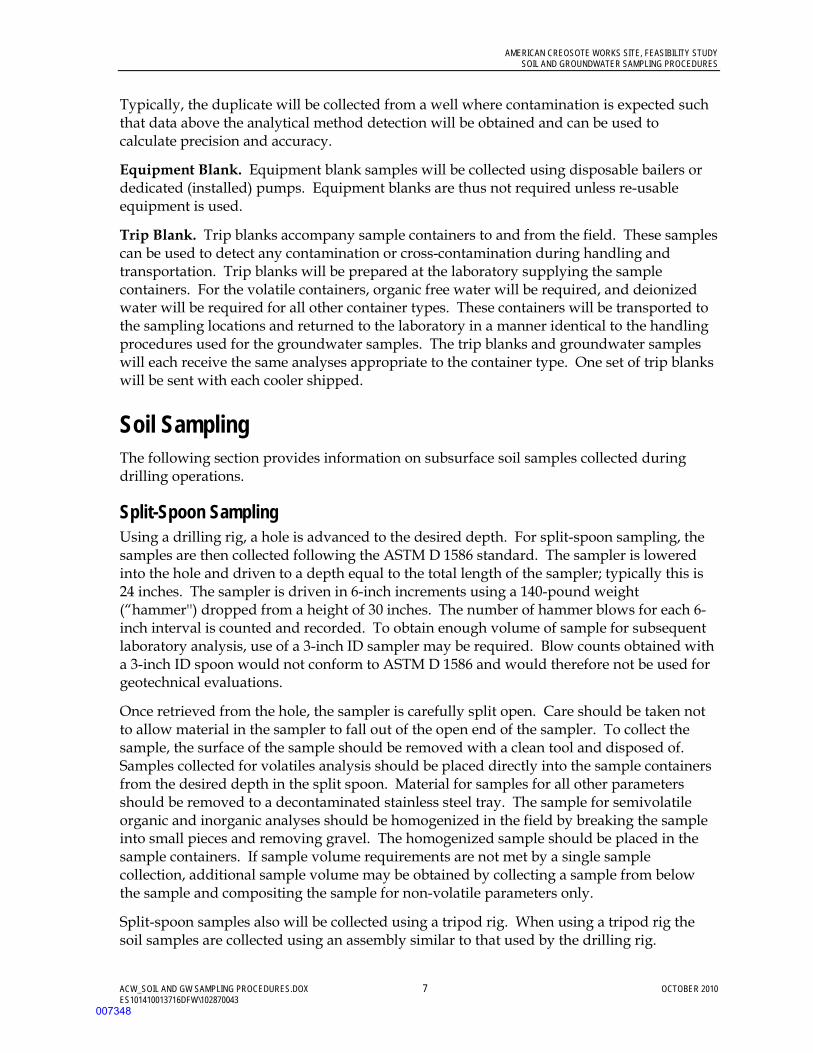
AMERICAN CREOSOTE WORKS SITE, FEASIBILITY STUDY SOIL AND GROUNDWATER SAMPLING PROCEDURES
ACW_SOIL AND GW SAMPLING PROCEDURES.DOX 7 OCTOBER 2010 ES101410013716DFW\102870043
Typically, the duplicate will be collected from a well where contamination is expected such that data above the analytical method detection will be obtained and can be used to calculate precision and accuracy.
Equipment Blank. Equipment blank samples will be collected using disposable bailers or dedicated (installed) pumps. Equipment blanks are thus not required unless re-usable equipment is used.
Trip Blank. Trip blanks accompany sample containers to and from the field. These samples can be used to detect any contamination or cross-contamination during handling and transportation. Trip blanks will be prepared at the laboratory supplying the sample containers. For the volatile containers, organic free water will be required, and deionized water will be required for all other container types. These containers will be transported to the sampling locations and returned to the laboratory in a manner identical to the handling procedures used for the groundwater samples. The trip blanks and groundwater samples will each receive the same analyses appropriate to the container type. One set of trip blanks will be sent with each cooler shipped.
Soil Sampling The following section provides information on subsurface soil samples collected during drilling operations.
Split-Spoon Sampling Using a drilling rig, a hole is advanced to the desired depth. For split-spoon sampling, the samples are then collected following the ASTM D 1586 standard. The sampler is lowered into the hole and driven to a depth equal to the total length of the sampler; typically this is 24 inches. The sampler is driven in 6-inch increments using a 140-pound weight (“hammer'') dropped from a height of 30 inches. The number of hammer blows for each 6-inch interval is counted and recorded. To obtain enough volume of sample for subsequent laboratory analysis, use of a 3-inch ID sampler may be required. Blow counts obtained with a 3-inch ID spoon would not conform to ASTM D 1586 and would therefore not be used for geotechnical evaluations.
Once retrieved from the hole, the sampler is carefully split open. Care should be taken not to allow material in the sampler to fall out of the open end of the sampler. To collect the sample, the surface of the sample should be removed with a clean tool and disposed of. Samples collected for volatiles analysis should be placed directly into the sample containers from the desired depth in the split spoon. Material for samples for all other parameters should be removed to a decontaminated stainless steel tray. The sample for semivolatile organic and inorganic analyses should be homogenized in the field by breaking the sample into small pieces and removing gravel. The homogenized sample should be placed in the sample containers. If sample volume requirements are not met by a single sample collection, additional sample volume may be obtained by collecting a sample from below the sample and compositing the sample for non-volatile parameters only.
Split-spoon samples also will be collected using a tripod rig. When using a tripod rig the soil samples are collected using an assembly similar to that used by the drilling rig.
007348
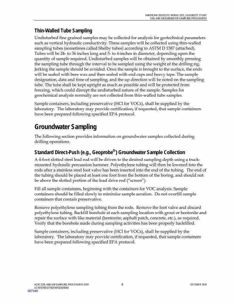
AMERICAN CREOSOTE WORKS SITE, FEASIBILITY STUDY SOIL AND GROUNDWATER SAMPLING PROCEDURES
ACW_SOIL AND GW SAMPLING PROCEDURES.DOX 8 OCTOBER 2010 ES101410013716DFW\102870043
Thin-Walled Tube Sampling Undisturbed fine grained samples may be collected for analysis for geotechnical parameters such as vertical hydraulic conductivity. These samples will be collected using thin-walled sampling tubes (sometimes called Shelby tubes) according to ASTM D 1587 (attached). Tubes will be 24- to 36 inches long and 3- to 4-inches in diameter, depending upon the quantity of sample required. Undisturbed samples will be obtained by smoothly pressing the sampling tube through the interval to be sampled using the weight of the drilling rig. Jerking the sample should be avoided. Once the sample is brought to the surface, the ends will be sealed with bees wax and then sealed with end caps and heavy tape. The sample designation, data and time of sampling, and the up direction will be noted on the sampling tube. The tube shall be kept upright as much as possible and will be protected from freezing, which could disrupt the undisturbed nature of the sample. Samples for geochemical analysis normally are not collected from thin-walled tube samples.
Sample containers, including preservative (HCl for VOCs), shall be supplied by the laboratory. The laboratory may provide certification, if requested, that sample containers have been prepared following specified EPA protocol.
Groundwater Sampling The following section provides information on groundwater samples collected during drilling operations.
Standard Direct-Push (e.g., Geoprobe) Groundwater Sample Collection A 4-foot slotted steel lead rod will be driven to the desired sampling depth using a truck-mounted hydraulic percussion hammer. Polyethylene tubing will then be lowered into the rods after a stainless steel foot valve has been inserted into the end of the tubing. The end of the tubing should be placed at least one foot from the bottom of the boring, and should not be above the slotted portion of the lead drive rod (“screen”).
Fill all sample containers, beginning with the containers for VOC analysis. Sample containers should be filled slowly to minimize sample aeration. Do not overfill sample containers that contain preservative.
Remove polyethylene sampling tubing from the rods. Remove the foot valve and discard polyethylene tubing. Backfill borehole at each sampling location with grout or bentonite and repair the surface with like material (bentonite, asphalt patch, concrete, etc.), as required. Verify that the borehole made during sampling activities has been properly backfilled.
Sample containers, including preservative (HCl for VOCs), shall be supplied by the laboratory. The laboratory may provide certification, if requested, that sample containers have been prepared following specified EPA protocol.
007349
Appendix C Capacity Test SOP
007350

APPENDIX C: CAPACITY TEST SOP
ACW_TTP_VER2.1.DOCX NOVEMBER 2011 ES111011092113DFW
(This page intentionally left blank)
007351
Designation: D 5472 – 93 (Reapproved 1999) e1
Standard Test Method forDetermining Specific Capacity and EstimatingTransmissivity at the Control Well 1
This standard is issued under the fixed designation D 5472; the number immediately following the designation indicates the year oforiginal adoption or, in the case of revision, the year of last revision. A number in parentheses indicates the year of last reapproval. Asuperscript epsilon (e) indicates an editorial change since the last revision or reapproval.
e1 NOTE—Section 10.2.1 was corrected editorially in August 1999.
1. Scope
1.1 This test describes a procedure for conducting a specificcapacity test, computing the specific capacity of a control well,and estimating the transmissivity in the vicinity of the controlwell. Specific capacity is the well yield per unit drawdown atan identified time after pumping started.
1.2 This test method is used in conjunction with TestMethod D 4050 for conducting withdrawal and injection welltests.
1.3 The method of determining transmissivity from specificcapacity is a variation of the nonequilibrium method of Theis(1) for determining transmissivity and storage coefficient of anaquifer. The Theis nonequilibrium method is given in TestMethod D 4106.
1.4 Limitations—The limitations of the technique for deter-mining transmissivity are primarily related to the correspon-dence between the field situation and the simplifying assump-tions of the Theis method.
1.5 The values stated in SI units are to be regarded asstandard.
1.6 This standard may involve hazardous materials, opera-tions, and equipment. This standard does not address safetyproblems associated with its use. It is the responsibility of theuser of this standard to establish appropriate safety and healthpractices and determine the applicability of regulatory limita-tions prior to use.
2. Referenced Documents
2.1 ASTM Standards:D 653 Terminology Relating to Soil, Rock, and Contained
Fluids2
D 4050 Test Method (Field Procedure) for Withdrawal andInjection Well Tests for Determining Hydraulic Propertiesof Aquifer Systems2
D 4106 Test Method for Analytical Procedure for Determin-ing Transmissivity and Storativity of Nonleaky ConfinedAquifers by the Theis Nonequilibrium Method2
D 4750 Test Method for Determining Subsurface LiquidLevels in a Borehole or Monitoring Well2
3. Terminology
3.1 Definitions:3.1.1 aquifer, confined—an aquifer bounded above and
below by confining beds and in which the static head is abovethe top of the aquifer.
3.1.2 aquifer, unconfined—an aquifer that has a water table.3.1.3 control well—well by which the head and flow in the
aquifer is changed by pumping, injecting, or imposing aconstant change of head.
3.1.4 head, static—the height above a standard datum of thesurface of a column of water that can be supported by the staticpressure at a given point.
3.1.5 hydraulic conductivity—(field aquifer test) the volumeof water at the existing kinematic viscosity that will move in aunit time under a unit hydraulic gradient through a unit areameasured at right angles to the direction of flow.
3.1.6 observation well—a well open to all or part of anaquifer, and used to make measurements.
3.1.7 specific capacity—well yield per unit drawdown at anidentified time after pumping started.
3.1.8 storage coeffıcient—the volume of water an aquiferreleases from or takes into storage per unit surface area of theaquifer per unit change in head.
3.1.9 transmissivity—the volume of water at the existingkinematic viscosity that will move in a unit time under a unithydraulic gradient through a unit width of the aquifer.
3.1.10 For definitions of other terms used in this method seeTerminology, D 653.
3.2 Symbols:Symbols and Dimensions:3.2.1 K—hydraulic conductivity [LT−1]3.2.2 m—saturated thickness [L]3.2.3 Q—discharge [L3T−1]3.2.4 Q/s—specific capacity [(L3T −1)L−1]3.2.5 r—well radius [L]3.2.6 s—drawdown [L]3.2.7 S—storage coefficient [dimensionless]3.2.8 T—transmissivity [L2T−1]3.2.9 T8—provisional value of transmissivity [L2T−1]3.2.10 t—elapsed time of pumping [T]
1 This test method is under the jurisdiction of ASTM Committee D-18 on Soiland Rock and is the direct responsibility of Subcommittee D18.21 on Ground Waterand Vadose Zone Investigations.
Current edition approved Nov. 15, 1993. Published January 1994.2 Annual Book of ASTM Standards, Vol 04.08.
1
Copyright © ASTM, 100 Barr Harbor Drive, West Conshohocken, PA 19428-2959, United States.
007352
3.2.11 u—r 2S/4Tt[dimensionless]3.2.12 W(u)—well function of “u” [dimensionless]3.2.13 c1— [W (u)/4p]
4. Significance and Use
4.1 Assumptions of the Theis(1) equation affect specificcapacity and transmissivity estimated from specific capacity.These assumptions are given below:
4.1.1 Aquifer is homogeneous and isotropic.4.1.2 Aquifer is horizontal, of uniform thickness, and infi-
nite in areal extent.4.1.3 Aquifer is confined by impermeable strata on its upper
and lower boundaries.4.1.4 Density gradient in the flowing fluid must be negli-
gible and the viscous resistance to flow must obey Darcy’sLaw.
4.1.5 Control well penetrates and receives water equallyfrom the entire thickness of the aquifer.
4.1.6 Control well has an infinitesimal diameter.4.1.7 Control well discharges at a constant rate.4.1.8 Control well operates at 100 percent efficiency.4.1.9 Aquifer remains saturated throughout the duration of
pumping.4.2 Implications of Assumptions and Limitations of Method.4.2.1 The simplifying assumptions necessary for solution of
the Theis equation and application of the method are neverfully met in a field test situation. The satisfactory use of themethod may depend upon the application of one or moreempirical correction factors being applied to the field data.
4.2.2 Generally the values of transmissivity derived fromspecific capacity vary from those values determined fromaquifer tests utilizing observation wells. These differences mayreflect 1) that specific-capacity represents the response of asmall part of the aquifer near the well and may be greatlyinfluenced by conditions near the well such as a gravel pack orgraded material resulting from well development, and 2)effects of well efficiency and partial penetration.
4.2.3 The values of transmissivity estimated from specificcapacity data are considered less accurate than values obtainedfrom analysis of drawdowns that are observed some distancefrom the pumped well.
5. Apparatus
5.1 Apparatus required for specific capacity testing includescontrol well, control well pump, discharge measuring equip-ment and water-level measuring equipment. The descriptionand function requirements of this equipment is given in TestMethod D 4050.
6. Conditioning Procedures
6.1 Conditioning procedures are conducted before the test toensure that the control well is properly equipped and that thewell discharge and water-level measuring equipment is opera-tional.
6.1.1 Equip the control well with a calibrated accumulatingwater meter or another type of calibrated well yield measuringdevice.
6.1.2 Provide the control well with a system for maintaininga constant discharge.
6.1.3 Equip control well for measuring the pretest waterlevel (prepumping water level) and pumping water levelsduring the specific capacity test.
6.1.4 Measure static water level immediately before startingthe pump.
6.1.5 Start pump and simultaneously measure elapsed timewith a stop watch or data recorder. After 3 to 5 minutes wellyield and drawdown should be measured and recorded.
6.1.6 If all the equipment is working properly, drawdownmeasurements can be obtained, and constant discharge main-tained, the equipment check can be ended.
6.1.7 Cease pumping and allow the water level to recover toits prepumping level before the specific capacity test procedure(Section 5) is initiated.
7. Test Procedure
7.1 Initiate well discharge.7.2 Measure the well yield and pumping water level in the
control well at predetermined time intervals, for example, 2-,5-, 10-, 20-, 30-, minutes after discharge is initiated. Adjust thedischarge rate during the test to maintain discharge within 5 %of the rate planned.
7.3 While test continues make the following calculations:7.3.1 Adjust drawdown for effects of desaturation of the
aquifer, if applicable (see Section 8).7.3.2 Determine the specific capacity (see Section 10) and
estimate transmissivity (see Section 11). If well bore storageeffects are negligible (see Section 9), compare the new value ofT8 to the value used to calculatec1, if the value is within 10 %,the test can be terminated.
7.3.3 If control well is not screened through the entirethickness of the aquifer, estimate the transmissivity of theaquifer following procedure in Sections 11 and 12.
8. Correction of Drawdown in an Unconfined Aquifer
8.1 The Theis equation is directly applicable to confinedaquifers and is suitable for use with limitations in unconfinedaquifers. If the aquifer is unconfined and drawdown is less than10 percent of the prepumping saturated thickness, little errorwill be introduced. If drawdown exceeds 25 percent of theprepumping saturated thickness, this test should not be used toestimate transmissivity. For unconfined aquifers with draw-down equal to 10 to 25 percent of the original saturatedthickness, correct the drawdown for the effects of reducedsaturated thickness by the following formula given by Jacob(2):
s85 s2~s2!2m (1)
where:s 5 measured drawdown in the control well,s8 5 corrected drawdown, andm 5 saturated thickness of the aquifer prior to pumping.
9. Well Bore Storage Effects
9.1 Evaluate the time criterion to determine if well-borestorage affects drawdown at the current duration of the test.Weeks(3) gives a time criterion modified after Papadopulosand Cooper(4) of t > 25 r 2/T after which drawdown in the
D 5472
2007353

control well is not affected by well-bore storage. For example,a well with a radius of 1 foot and aT of 1000 ft2/day has a timecriterion of t > 25 r 2/T 5 t > 25 (1)2/10005 t > 0.025days5 t > 36 min.
10. Computation of Specific Capacity
10.1 Record the drawdown and the time since pumpingstarted.
10.2 Compute the specific capacity of the control well fromthe average well yield (Q) and the drawdown (s):
Specific Capacity5 Q/s@~L3T21!L21# (2)
10.2.1 An example of specific capacity where discharge isgiven in American Standard Units (1000 gallons per minute)and drawdown in feet (50):
Specific Capacity5[1000 gpm (1440 min/day/7.48 gal/ft3)]/50 ft 53850 [(ft3/day)]ft
11. Estimate Transmissivity from Specific Capacity
11.1 A modification of the Theis(1) nonequilibrium equa-tion is used to evaluate transmissivity data derived fromspecific capacity as follows:
T 5 @W~u!/4p#Q/s (3)
11.1.1 A general form of the equation is:
T8 5 c1Q/s (4)
where:c 1 5 W ( u)/4p.
11.1.2 Calculate the value ofc 1 from a provisional value oftransmissivity,T8, estimated storage coefficient,S, well radius,r, and duration of the test,t. An example of the computation ofc1 using field values of discharge in American units is asfollows:
where:T8 5 11 000 ft2/day,S 5 2 3 10 −5
r 5 0.67 ft (16-in. diameter pipe),t 5 0.50 days
C1 5 W (u)/4pW (u) 5 (−0.5772 − Ln[u])
where:u 5 (r2S)/(4Tt)5 4.08093 10 −10
C1 5 (−0.5772 − Ln[4.08093 10−10)/4p]C1 5 (−0.5772 − Ln[4.08093 10−10])/12.5664C1 5 (−0.5772 − [−21.6195])/12.5664C1 5 21.0423/12.56645 1.6745
11.1.3 Calculate transmissivity from Eq 4;T 5 c1Q/s,AssumeQ/s 5 3850 [(ft3/day)/ft]T 5 1.67453 38505 6450 ft2/day (rounded)
11.1.4 If transmissivity calculated in 11.1.3 is not within10 % of the provisional transmissivity,T8, recalculatec1 fromthe new value of transmissivity and recalculate transmissivityby formula. In the example, because 6450 ft2/day is 59 percentof the initial T8 value of the 11 000 ft2/day, a more accuratec1
can be computed to match the newT8 value.T8 5 6450 ft2/day
S5 2 3 10−5
c1 5 W ( u)/4pW (u) 5 (−0.5772 − Ln[u])
where:u 5 (r2S)/(4Tt)5 8.97803 10 −6 5 6.95973 10−10
C1 5 (−0.5772 − Ln6.95973 10 −10)/4pC1 5 (−0.5772 − Ln 6.95973 10−10)/12.5664C1 5 (−0.5772 − (−21.0857)/12.5664C1 5 20.5085/12.56645 1.6320
thus:T8 5 C1(Q/s)5 1.63203 38505 6300 ft2/day (rounded).
The new value of transmissivity is within 10 % of thevalue used to compute transmissivity.
11.1.5 To obtain SI units, multiply American units by9.2903 10−2 for m2/day.
NOTE 1—The initial estimates of transmissivity can be based on valuesof transmissivity and storage of the aquifer determined at other locationsor from a general knowledge of the aquifer properties. The transmissivitycould be estimated from driller’s logs using methods described byGutentag and others(5). The storage coefficient can be estimated forunconfined aquifer as 0.2 and for confined aquifers as b3 10 −6, wherebis the thickness of the aquifer in feet. In areas where aquifer properties arenot known and drillers log data are lacking, the following values, modifiedfrom Harlan, Kolm, and Gutentag(6) can be used as initial estimates ofc1:
Confined aquifers 1.6Unconfined aquifers 0.8
12. Correction of Transmissivity for Partially PenetratingWell
12.1 If the full aquifer thickness is not screened, the value ofT8 represents the transmissivity of the screened section of theaquifer. To estimate the transmissivity of the full thickness ofthe aquifer, divide estimated transmissivity by the length of thescreened interval to compute the hydraulic conductivity (K).After computing (K) the hydraulic conductivity value ismultiplied by the entire thickness of the saturated thickness (m)of the aquifer to compute an estimate of transmissivity as:T 5 Km.
13. Report
13.1 Prepare a report containing all data, including a de-scription of the field site, well construction, plots of pumpingwater level and well discharge with time.
13.2 Present analysis of data, using iteration techniques forc, when results differ from initial input values ofT andS.
13.3 Compare estimated test conditions with the test methodassumptions listed in 4.1.
14. Precision and Bias
14.1 It is not practicable to specify the precision of thisprocedure because the response of aquifer systems duringaquifer tests is dependent upon ambient system stresses. Nostatement can be made about bias because no true referencevalues exist.
15. Keywords
15.1 aquifers; aquifer tests; control wells; hydraulic conduc-tivity; observation wells; specific capacity; storage coefficient;transmissivity; unconfined aquifers
D 5472
3007354
REFERENCES
(1) Theis, C. V., 1935, The Relation Between the Lowering of Duration ofDischarge of a Well Using Ground-Water Storage:American Geo-physical Union Transactions, v. 16. pt. 2, p. 519–524.
(2) Jacob, C. E., “Determining the Permeability of Water-Table Aquifers,”in Bentall, Ray, Compiler, “Methods of Determining Permeability,Transmissibility, and Drawdown,” U.S. Geological Survey Water-Supply Paper 1536-I, 1963, pp. 245–271.
(3) Weeks, E. P., 1978, Aquifer Tests—the State of the Art in Hydrology:in Proceedings Invitational Well-Testing Symposium, October 19–21,1977, Lawrence Berkeley Laboratory, University of California, LBL-7027, UC-66, TID 4500-R66, p. 14–26.
(4) Papadopulos, I. S., and Cooper, H. H., Jr., 1967, Drawdown in a Wellof Large Diameter: Water Resources Research, v. 3, no. 1, p. 241–244.
(5) Gutentag, E. D., Heimes, F. J., Krothe, N. C., Luckey, R. R., andWeeks, J. B., 1984, Geohydrology of the High Plains Aquifer in partsof Colorado, Kansas, Nebraska, New Mexico, Oklahoma, SouthDakota, Texas, and Wyoming: U.S. Geological Survey ProfessionalPaper 1400-B, 63 p.
(6) Harlan, R. L., Kolm, K. E., and Gutentag, E. D., 1989, Water-WellDesign and Construction: Elsevier, Amsterdam, 205, p.
The American Society for Testing and Materials takes no position respecting the validity of any patent rights asserted in connectionwith any item mentioned in this standard. Users of this standard are expressly advised that determination of the validity of any suchpatent rights, and the risk of infringement of such rights, are entirely their own responsibility.
This standard is subject to revision at any time by the responsible technical committee and must be reviewed every five years andif not revised, either reapproved or withdrawn. Your comments are invited either for revision of this standard or for additional standardsand should be addressed to ASTM Headquarters. Your comments will receive careful consideration at a meeting of the responsibletechnical committee, which you may attend. If you feel that your comments have not received a fair hearing you should make yourviews known to the ASTM Committee on Standards, at the address shown below.
This standard is copyrighted by ASTM, 100 Barr Harbor Drive, PO Box C700, West Conshohocken, PA 19428-2959, United States.Individual reprints (single or multiple copies) of this standard may be obtained by contacting ASTM at the above address or at610-832-9585 (phone), 610-832-9555 (fax), or [email protected] (e-mail); or through the ASTM website (www.astm.org).
D 5472
4007355

Appendix D Project Schedule
007356

APPENDIX D: PROJECT SCHEDULE
ACW_TTP_VER2.1.DOCX NOVEMBER 2011 ES111011092113DFW
(This page intentionally left blank)
007357
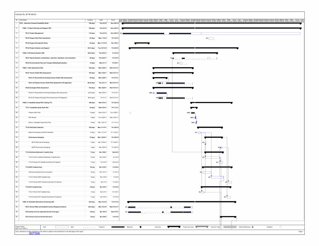
ID Task Name Duration Start Finish
1 TO51 - American Creosote Feasibility Study 738 days Thu 9/2/10 Sun 6/30/13
2 TASK 1: Project Planning and Support (PP) 738 days Thu 9/2/10 Sun 6/30/13
3 PP.01 Project Management 718 days Thu 9/2/10 Sun 6/30/13
4 PP.02 Prepare Work Plan Amendment 20 days Mon 1/16/12 Fri 2/10/12
5 PP.03 Prepare Site Specific Plans 55 days Mon 11/15/10 Sat 1/29/11
10 PP.04 Project Initiation and Support 447.6 days Tue 10/12/10 Fri 6/29/12
13 TASK 6: DE Data Evaluation (DE) 180.9 days Thu 6/23/11 Fri 3/2/12
14 DE.01 Data Evaluation (combination, reduction, tabulation, and evaluation) 26 days Thu 6/23/11 Fri 3/2/12
15 DE.02 Environmental Fate and Transport Modeling/Evaluation 10 days Mon 8/1/11 Fri 9/9/11
16 TASK 7: Risk Assessment (RA) 163 days Mon 2/28/11 Wed 10/12/11
17 RA.01 Human Health Risk Assessment 163 days Mon 2/28/11 Wed 10/12/11
18 RA.01.01 Review/Revise Existing Human Health Risk Assessment 55 days Mon 2/28/11 Fri 5/13/11
23 RA.01.02 Prepare Human Health Risk Assessment (FS Appendix) 86.46 days Thu 3/31/11 Wed 10/12/11
24 RA.02 Ecological Risk Assessment 163 days Mon 2/28/11 Wed 10/12/11
25 RA.02.01 Review/Revise Existing Ecological Risk Assessment 43.25 days Mon 2/28/11 Fri 5/13/11
26 RA.02.02 Prepare Ecological Risk Assessment (FS Appendix) 89.43 days Fri 4/1/11 Wed 10/12/11
27 TASK 8: Treatability Study/Pilot Testing (TT) 168 days Wed 10/5/11 Fri 5/25/12
28 TT.01 Treatability Study Work Plan 23 days Wed 10/5/11 Fri 11/4/11
29 Prepare Work Plan 15 days Wed 10/5/11 Tue 10/25/11
30 EPA Review 5 days Tue 10/25/11 Mon 10/31/11
31 Revise Treatability Study Work Plan 5 days Mon 10/31/11 Fri 11/4/11
32 TT.02 Field Data Collection 100 days Mon 11/14/11 Fri 3/30/12
33 Baseline Sampling and Well Installation 10 days Mon 11/14/11 Fri 11/25/11
34 Performance Sampling 70 days Mon 12/26/11 Fri 3/30/12
35 ISCO Peformance Sampling 5 days Mon 12/26/11 Fri 12/30/11
36 SEPR Performance Sampling 5 days Mon 3/26/12 Fri 3/30/12
37 TT.03 Solidification/Stabilization Treatability Study 73 days Mon 12/26/11 Wed 4/4/12
38 TT.03.01 Perform Solidification/Stabilization Treatability Study 60 days Mon 12/26/11 Fri 3/16/12
39 TT.03.02 Prepare S/S Treatability Study Report (FS Appendix) 15 days Thu 3/15/12 Wed 4/4/12
40 TT.04 SEPR Treatability Study 120 days Mon 12/12/11 Fri 5/25/12
41 Well Rehab and Baseline Recovery Evaluation 35 days Mon 12/12/11 Fri 1/27/12
42 TT.04.01 Perform SEPR Treatability Study 50 days Mon 1/30/12 Fri 4/6/12
43 TT.04.02 Prepare SEPR Treatability Study Report (FS Appendix) 15 days Mon 5/7/12 Fri 5/25/12
44 TT.05 ISCO Treatability Study 120 days Mon 12/5/11 Fri 5/18/12
45 TT.05.01 Perform ISCO Treatability Study 10 days Mon 12/5/11 Fri 12/16/11
46 TT.05.02 Prepare ISCO Treatability Study Report (FS Appendix) 15 days Mon 4/30/12 Fri 5/18/12
47 TASK 10: Remedial Alternatives Screening (RS) 445 days Mon 10/4/10 Fri 6/15/12
48 RS.01 Revise RAOs and Establish General Response Actions 66.9 days Mon 10/4/10 Wed 10/12/11
49 RS.02 Identify and Screen Applicable Remedial Technologies 148 days Mon 10/4/10 Wed 10/12/11
50 RS.03 Develop and Screen Remedial Alternatives 60 days Mon 3/26/12 Fri 6/15/12
0%
0%
0%
0%
0%
100%
0%
100%
100%
100%
0%
0%
0%
0%
0%
0%
0%
0%
0%
0%
0%
0%
M E B M E B M E B M E B M E B M E B M E B M E B M E B M E B M E B M E B M E B M E B M E B M E B M E B M E B M E B M E B M E B M E B M E B M E B M E B M E B M E B M E B M E B M E B M E B M E B M E B M E B M E B Mgust Septe Octobe Novem Decem Januar Febru March April May June July August Septe Octobe Novem Decem Januar Febru March April May June July August Septe Octobe Novem Decem Januar Febru March April May June July
Task Split Progress Milestone Summary Project Summary External Tasks External Milestone Deadline
Contract No. EP-W-06-021
Use or disclosure of data contained on this sheet is subject to the restrictions on the title page of this report. Page 1
Project: NameDate: Tue 10/25/11
007358

(This page intentionally left blank)
007359

ID Task Name Duration Start Finish
51 Develop Remedial Alternatives Concepts and Quantities 60 days Mon 3/26/12 Fri 6/15/12
52 Cost Estimating 20 days Mon 5/21/12 Fri 6/15/12
53 TASK 11: Remedial Alternatives Evaluation (RE) 15 days Mon 6/4/12 Fri 6/22/12
54 RE.01 Detailed Analysis of Alternatives 10 days Mon 6/4/12 Fri 6/15/12
55 RE.02 Comparative Analysis of Alternatives 5 days Mon 6/18/12 Fri 6/22/12
56 TASK 12: Feasibility Study Report (FS) 466 days Thu 12/9/10 Thu 9/20/12
57 FS.01 Prepare Draft Feasibility Study Report 455 days Thu 12/9/10 Wed 9/5/12
58 First Draft 432 days Thu 12/9/10 Fri 8/3/12
59 Prepare First Draft 251 days Thu 12/9/10 Fri 7/20/12
60 EPA Review 10 days Mon 7/23/12 Fri 8/3/12
61 Second Draft 23 days Mon 8/6/12 Wed 9/5/12
62 Incorporate 1st Draft Comments/Prepare Second Draft 12 days Mon 8/6/12 Tue 8/21/12
63 EPA Review 11 days Wed 8/22/12 Wed 9/5/12
64 FS.02 Prepare Final Feasibility Study Report 11 days Thu 9/6/12 Thu 9/20/12
65 Incorporate 2nd Draft Comments/Prepare Final Draft 11 days Thu 9/6/12 Thu 9/20/12
66 TASK 13: Post FS Support (PR) 104 days Fri 9/21/12 Wed 2/13/13
67 PR.01 Provide Post FS Meeting Support 84 days Fri 9/21/12 Wed 1/16/13
68 PR.02 Provide Post FS Technical Assistance 84 days Fri 9/21/12 Wed 1/16/13
69 PR.03 Prepare Feasibility Study Addendum 20 days Thu 1/17/13 Wed 2/13/13
70 Task 15: Task Order Closeout (CO) 10 days Tue 6/18/13 Sun 6/30/13
71 CO.01 File Closeout and Archiving 10 days Tue 6/18/13 Sun 6/30/13
72 CO.02 Prepare the Task Order Closeout Report (TOCR) 10 days Tue 6/18/13 Sun 6/30/13
0%
0%
0%
0%
0%
0%
0%
0%
0%
0%
0%
0%
0%
0%
M E B M E B M E B M E B M E B M E B M E B M E B M E B M E B M E B M E B M E B M E B M E B M E B M E B M E B M E B M E B M E B M E B M E B M E B M E B M E B M E B M E B M E B M E B M E B M E B M E B M E B M E B Mgust Septe Octobe Novem Decem Januar Febru March April May June July August Septe Octobe Novem Decem Januar Febru March April May June July August Septe Octobe Novem Decem Januar Febru March April May June July
Task Split Progress Milestone Summary Project Summary External Tasks External Milestone Deadline
Contract No. EP-W-06-021
Use or disclosure of data contained on this sheet is subject to the restrictions on the title page of this report. Page 2
Project: NameDate: Tue 10/25/11
007360

(This page intentionally left blank)
007361