ReLife: Transitional Housing for Victims of Natural Disaster
113
University of South Florida Scholar Commons Graduate eses and Dissertations Graduate School 11-20-2009 ReLife: Transitional Housing for Victims of Natural Disaster Alexander B. Smith University of South Florida Follow this and additional works at: hps://scholarcommons.usf.edu/etd Part of the American Studies Commons is esis is brought to you for free and open access by the Graduate School at Scholar Commons. It has been accepted for inclusion in Graduate eses and Dissertations by an authorized administrator of Scholar Commons. For more information, please contact [email protected]. Scholar Commons Citation Smith, Alexander B., "ReLife: Transitional Housing for Victims of Natural Disaster" (2009). Graduate eses and Dissertations. hps://scholarcommons.usf.edu/etd/21
Transcript of ReLife: Transitional Housing for Victims of Natural Disaster
University of South FloridaScholar Commons
Graduate Theses and Dissertations Graduate School
11-20-2009
ReLife: Transitional Housing for Victims of NaturalDisasterAlexander B. SmithUniversity of South Florida
Follow this and additional works at: https://scholarcommons.usf.edu/etd
Part of the American Studies Commons
This Thesis is brought to you for free and open access by the Graduate School at Scholar Commons. It has been accepted for inclusion in GraduateTheses and Dissertations by an authorized administrator of Scholar Commons. For more information, please contact [email protected].
Scholar Commons CitationSmith, Alexander B., "ReLife: Transitional Housing for Victims of Natural Disaster" (2009). Graduate Theses and Dissertations.https://scholarcommons.usf.edu/etd/21

ReLife: Transitional Housing for Victims of Natural Disaster
by
Alexander B. Smith
A thesis submitted in partial fulfillmentof the requirements for the degree of
Master of ArchitectureSchool of Architecture and Community Design
College of The ArtsUniversity of South Florida
Major Professor: Stanley Russell, M.ArchTimothy N. Clemmons, M.Arch
Kenneth Cowart, M.Arch
Date of Approval:November 20, 2009
Keywords: humanitarian, aid, home, design, catastrophe, recovery
© Copyright 2009, Alexander B. Smith
DEDICATION
I would like to dedicate this Thesis Document to my family who, with there love and support,
inspired me to study architecture. They were always there to help me through school. Thanks
to my parents for providing me the foundation for excellence in everything I commit to, my
grandparents for there generosity in assisting me throughout college, my brothers for teaching me
skills to endure when troubles arise, and my girlfriend for tolerating the long hours and late nights
that school required of me.
I also want to dedicate this Thesis to all the past, present, and future victims of disasters, especially
those of Hurricane Katrina. Your pain and suffering experienced during that disaster inspired me to
act and commit my time to helping improve your quality of life and those who may be affected in the
future.
ACKNOWLEDGEMENTS
I would like to thank my Thesis Committee for helping me throughout this process. In recognition
of his confidence, guidance, wisdom, and assistance freely given in helping me complete this Thesis
study I would like to recognize Professor Stanley Russell. He has helped me develop my skills to
prepare me for architecture and design for the rest of my life. Also thank you to Tim Clemmons and
Ken Cowart who always provided great insight into the design that kept me motivated to continue
my research.
TABLE OF CONTENTS i
List of Figures vi
Abstract xii
Project Research 1
Issue 1
Background 3
Design Intent 4
Process 10
Development 13
Case Studies 15
Disaster Housing Pilot Project - FEMA 17
Programmatic Space and Variability 17
Construction and Assembly 18
Mobility 18
Materiality 18
Paper Log Houses - Shigeru Ban 19
i
Programmatic Space and Variability 19
Construction and Assembly 20
Mobility 20
Materiality 21
Portable House - Office of Mobile Design 22
Programmatic Space and Variability 22
Construction and Assembly 23
Mobility 23
Materiality 23
Case Study Benefits 24
Disaster Pilot Projects 24
Paper Log Houses 25
Portable House 25
Other Studies 26
triPOD: a plug and Play housing system 26
ME:LU Modular Expandable Living Unit 27
Second-Life Iraqi Housing 28
Programmatic Spaces 29
Qualities of Space 30
ii

Space Usage and Relationships 31
Levels of Privacy 34
Unit Areas 36
Scenario Analysis 39
Site Selection 39
Flood Scenario 43
Wildfire Scenario 44
Hurricane Scenario 45
Concept Development 47
Conceptual Schematics 48
Design Development 52
Disaster Timeline 53
Principles of Design 54
Efficient Shipping 55
Connection to the Ground 56
Specific Site Attributes and Design 57
Gulfport Site Attributes 58
Gulfport House 1 59
Gulfport House 2 59
iii

Gulfport House 3 59
Gulfport Unit Designs 60
Gulfport Unit 1 60
Gulfport Unit 2 61
Gulfport Unit 3 62
Apollo Beach Site Attributes 63
Apollo Beach House 1 64
Apollo Beach House 2 64
Apollo Beach House 3 64
Apollo Beach Unit Designs 65
Apollo Beach Unit 1 65
Apollo Beach Unit 2 66
Apollo Beach Unit 3 67
Sectional Qualities 68
Material Study 69
Process of Designing a Unit 70
How to Build 70
How to Choose Type 72
Permanent Floor Plan Expansion 73
iv

How To Choose Unit Size 74
Unit Componenets 75
SIP Panel Options 77
Other Accessories 79
Utility Lines In SIP Panels 80
Extruded Structural System 80
Construction Assembly of Unit 81
Temporary Unit Timeline 82
Permanent Unit Timeline 84
Final Designs 86
Temporary Unit 86
Permanent Unit 88
Product Media 90
Unit Product Guide 91
Bibliography 93
v

LIST OF FIGURES
Figure 1. Thesis Poster xFigure 2. Hurricane destruction. 1Figure 3. Wildfire destruction. 1Figure 4. Flood destruction. 1Figure 5. Earthquake destruction. 2Figure 6. Hurricane prediction. 2Figure 7. Temporary shelters. 2Figure 8. Trailer interior. 3Figure 9. Trailer victim. 4Figure 10. Prefab construction. 5Figure 11. Trailer community. 6Figure 12. Samuel Mockbee architecture. 7Figure 13. Passive design. 7Figure 14. Grey water system. 8Figure 15. Doors Prototype. 8Figure 16. Push Button House. 8Figure 17. Red-Cross relief. 9Figure 18. Manufacturing industry. 10Figure 19. IKEA directions. 10Figure 20. Transitional house. 11Figure 21.Photovoltaic array. 12Figure 22. Disaster Pilot Project interior and exterior photos. 17Figure 23. Heston Modular example plan. 17Figure 24. Construction of Disaster Pilot Project. 18Figure 25. Transportation of Heston Modular. 18
vi

Figure 26. Individual plywood material unit. 18Figure 27. Laminated plywood sheathing. 18Figure 28. Construction of paper log houses. 19Figure 29. Paper log house plan in India. 19Figure 30. Individual bamboo material unit. 20 Figure 31. Paper Log House elevation and canopy. 20Figure 32. Paper Log Houses in Japan. 21Figure 33. Paper Log Houses in Turkey. 21Figure 34. Paper Log Houses in India. 21Figure 35. Portable house interior and exterior photos. 22Figure 36. Exterior facade of portable house. 22Figure 37. Portable house elevations. 22Figure 38. 3-D exploded axonometrics of Portable House. 23Figure 39. Transportation of Portable House. 23Figure 40. Rendering of Portable House. 23Figure 41. Pilot Project Diagram. 24Figure 42. Log House Diagram. 25Figure 43. Portable House Diagram. 25Figure 44. Construction of triPOD prefabricated modular system. 26Figure 45. Diagram of triPOD. 26Figure 46. Perspectives of ME:LU. 27Figure 47. Section-perspective of ME:LU. 27Figure 48. 3-D rendering of ME:LU. 27Figure 49. Modes of transport for Second-Life Iraqi Housing. 28Figure 50. Assembly of Second-Life Housing. 28Figure 51. Perspective of Second-Life. 28Figure 52. Daytime Usage Breakdown. 31Figure 53. Diagram of spaces with associations. 32Figure 54. Maximum occucpancy level for each room. 33Figure 55. Levels of privacy in plan and perspective. 34Figure 56. Privacy with floor plan. 34Figure 57. Early groupings of spaces with one another. 35
vii

Figure 58. Space Areas within Unit B. 35Figure 59. Ratio of Unit Areas to one another. 35Figure 60. Comparison of Unit Areas. 35Figure 61. Diagram of sites US wide. 39Figure 62. Diagram of natural disasters throughout Florida. 42Figure 63. Site research for flood scenario. 43Figure 64. Map of flood scenario. 43Figure 65. Site research for wildfire scenario. 44Figure 66. Map of wildfire scenario. 44Figure 67. Site research for hurricane scenario. 45Figure 68. Map of Gulfport hurricane scenario. 46Figure 69. Map of Apollo Beach hurricane scenario. 46Figure 70. Models of conceptual development. 47Figure 71. Detail of structural member with SIP panel. 48Figure 72. 3-D detail of structural system. 48Figure 73. Seven variations of unit B. 49Figure 74. Five sites within Apollo Beach scenario. 50Figure 75. Five sites within Gulfport scenario. 50Figure 76. Schematic plan and section of Unit A1. 51Figure 77. Schematic plan and section of Unit A2. 51Figure 78. Schematic plan and section of Unit B1. 51Figure 79. Schematic plan and section of Unit C1. 51Figure 80. Schematic plan and section of Unit C2. 51Figure 81. Disaster Timeline. 52Figure 82. Unit A Panels Stacked. 55Figure 83. Unit Stacked in Shipping Container. 55Figure 84. Auger Drill. 56Figure 85. Footing Assembly. 56Figure 86. Footing Cross-Section. 56Figure 87. Gulfport Site Graphic. 58Figure 88. Gulfport Site Model. 58Figure 89. Gulfport House 1. 59
viii

Figure 90. Gulfport House 2. 59Figure 91. Gulfport House 1. 59Figure 92. Unit 1 Initial Design. 60Figure 93. Unit 1 Initial Plan. 60Figure 94. Unit 1 Initial Model. 60Figure 95. Unit 1 Secondary Plan. 60Figure 96. Unit 1 Secondary Design. 60Figure 97. Unit 1 Secondary Model. 60Figure 98. Unit 2 Initial Design. 61Figure 99. Unit 2 Initial Plan. 61Figure 100. Unit 2 Initial Model. 61Figure 101. Unit 2 Secondary Plan. 61Figure 102. Unit 2 Secondary Design. 61Figure 103. Unit 2 Secondary Model. 61Figure 104. Unit 3 Initial Design. 62Figure 105. Unit 3 Initial Plan. 62Figure 106. Unit 3 Initial Model. 62Figure 107. Unit 3 Secondary Plan. 62Figure 108. Unit 3 Secondary Design. 62Figure 109. Unit 3 Secondary Model. 62Figure 110. Apollo Beach Site Graphic. 63Figure 111. Apollo Beach Site Model. 63Figure 112. Apollo Beach 4. 64Figure 113. Apollo Beach 5. 64Figure 114. Apollo Beach 6. 64Figure 115. Unit 4 Initial Design. 65Figure 116. Unit 4 Initial Plan. 65Figure 117. Unit 4 Initial Model. 65Figure 118. Unit 4 Secondary Plan. 65Figure 119. Unit 4 Secondary Design. 65Figure 120. Unit 4 Secondary Model. 65Figure 121. Unit 5 Initial Design. 66
ix
Figure 122. Unit 5 Initial Plan. 66Figure 123. Unit 5 Initial Model. 66Figure 124. Unit 5 Secondary Plan. 66Figure 125. Unit 5 Secondary Design. 66Figure 125. Unit 5 Secondary Design. 66Figure 126. Unit 5 Secondary Model. 66Figure 127. Unit 6 Initial Design. 67Figure 128. Unit 6 Initial Plan. 67Figure 129. Unit 6 Initial Model. 67Figure 130. Unit 6 Secondary Plan. 67Figure 131. Unit 6 Secondary Design. 67Figure 132. Unit 6 Secondary Model. 67Figure 133. Section Model 1. 68Figure 134. Section Model 2. 68Figure 135. Unit 3 Render. 69Figure 136. Unit 6 Render. 69Figure 137. Unit 1 Render. 69Figure 138. Unit 4 Render. 69Figure 139. How To Build Diagram. 71Figure 140. Temporary ReLife Unit. 72Figure 141. Permanent ReLife Unit. 72Figure 142. Permanent Unit Stage 1. 73Figure 143. Permanent Unit Stage 2. 73Figure 144. Permanent Unit Stage 3. 73Figure 145. Unit A Spaces. 74Figure 146. Unit B Spaces. 74Figure 147. Unit C Spaces. 74Figure 148. Footings. 75Figure 149. Living Space. 75Figure 150. Bedroom Space. 75Figure 151. Porch. 76Figure 152. Bathroom Space. 76
x

Figure 153. Kitchen/Dining Space. 76Figure 154. Window Wall Panel. 77Figure 155. Wall Panel. 77Figure 156. Floor Panel. 77Figure 157. SF-RE Panel. 78Figure 158. Door Panel. 78Figure 159. Roof/Ceiling Panel. 78Figure 160. Railings. 79Figure 161. Steps. 79Figure 162. Ramp. 79Figure 163. SIP Panel Utilities. 80Figure 164. Extruded Structural System. 80Figure 165. Temporary Unit Timeline. 82Figure 166. Temporary Unit Digram. 83Figure 167. Permanent Unit Timeline. 84Figure 168. Permanent Unit Digram. 85Figure 169. Temporary Unit Render. 86Figure 170. Temporary Unit Plan. 86Figure 171. Temporary Unit Section. 86Figure 172. Temporary Unit Model. 87Figure 173. Temporary Unit Model. 87Figure 174. Temporary Unit Model. 87Figure 175. Permanent Unit Render. 88Figure 176. Permanent Unit Plan. 88Figure 177. Permanent Unit Section. 88Figure 178. Permanent Unit Model. 89Figure 179. Permanent Unit Model. 89Figure 180. Permanent Unit Model. 89Figure 181. Product Guide P1,P8. 91Figure 182. Product Guide P2,P3. 91Figure 183. Product Guide P4,P5. 92Figure 184. Product Guide P6,P7. 92
xi

RELIFE: TRANSITIONAL HOUSING FOR VICTIMS OF NATURAL DISASTER
ALEANDER B. SMITH
ABSTRACT
Recent natural disasters around the globe have left individuals without shelter. Governments have
shown slow response for these victims with examples seen from the aftermath of Hurricane Katrina.
People are still living in structures that are hazardous to their health, insufficient for normal day
activity, and socially unacceptable. With the rising numbers of victims and the slow response of
governments to provide solutions, a new typology must be designed.
This thesis proposes a new typology that will create a responsive design that is efficient, aesthetic,
environmentally conscious, and ready for implementation. Transitional housing can be defined as
housing that is used during the rebuilding phase for the victims. It is not just an emergency shelter,
but a structure that provides a return to normalcy for the victim. For the design to be efficient it
must be easily constructed, shipped, and assembled on site. Aesthetic design, for the purpose of
xii
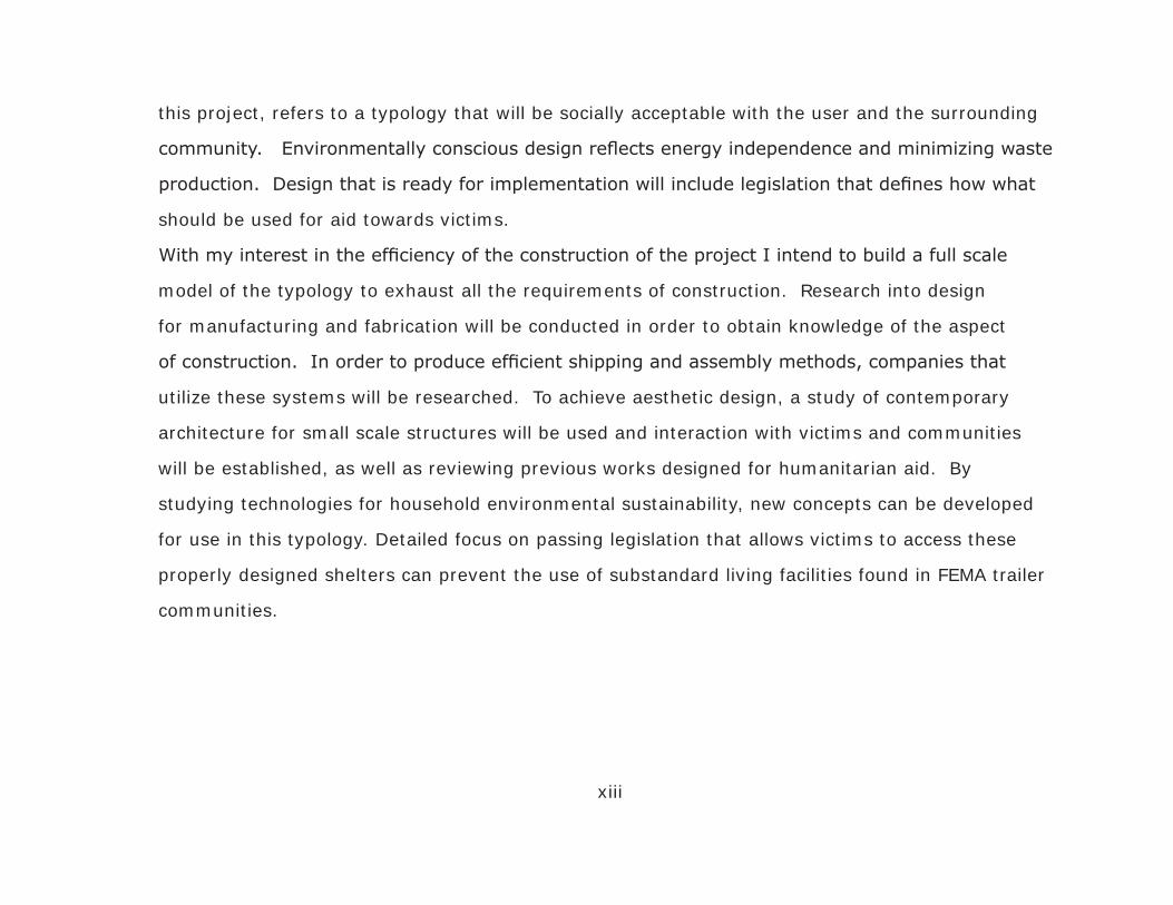
this project, refers to a typology that will be socially acceptable with the user and the surrounding
community. Environmentally conscious design reflects energy independence and minimizing waste
production. Design that is ready for implementation will include legislation that defines how what
should be used for aid towards victims.
With my interest in the efficiency of the construction of the project I intend to build a full scale
model of the typology to exhaust all the requirements of construction. Research into design
for manufacturing and fabrication will be conducted in order to obtain knowledge of the aspect
of construction. In order to produce efficient shipping and assembly methods, companies that
utilize these systems will be researched. To achieve aesthetic design, a study of contemporary
architecture for small scale structures will be used and interaction with victims and communities
will be established, as well as reviewing previous works designed for humanitarian aid. By
studying technologies for household environmental sustainability, new concepts can be developed
for use in this typology. Detailed focus on passing legislation that allows victims to access these
properly designed shelters can prevent the use of substandard living facilities found in FEMA trailer
communities.
xiii

Figure 1. Thesis Poster.
xiv

PROJECT RESEARCH
Recent disasters around the world have left individuals without
shelter. Governments have shown slow response for these victims
with examples seen from the aftermath of Hurricane Katrina. Living
conditions in current temporary housing units are causing health
problems and are socially unacceptable. With the rising number of
victims and the slow response of government to provide shelter, a new
typology must be designed. This new typology will create a responsive
design that is efficient, aesthetically acceptable, environmentally
conscious, and ready for implementation into the current framework
of society.
Issue
The Federal Emergency Management Agency (FEMA), part of the
Department of Homeland Security, is responsible for disaster relief
for catastrophic events in the United States. FEMA defines a major
disaster as a “result from a hurricane, earthquake, flood, tornado,
1
Figure 2. Hurricane destruction.
Figure 3. Wildfire destruction.
Figure 4. Flood destruction.

or major fire which the President determines warrants supplemental
federal aid”.1 Looking at hurricanes only, the April predictions for the
2009 season predict that 12 storms will hit the Gulf Coast region.2 The
victims that are affected by these disasters are usually displaced from
their homes during the initial emergency period, which has programs
that are an effective means of response. Problems arise during the
transitional period that lies between the initial emergency response
and full recovery of their previous living standards. Areas where there
are a large number of low income individuals are hit the worse because
of their lack of ability to provide funds for recovery. These areas are
where FEMA is needed the most but unfortunately not providing that
needed support. “Disaster recovery programs are failing to provide
long-term housing stability to low-income families because of the
programmatic focus on temporary as opposed to permanent housing.”3
Recent disaster plans passed by the government have restricted the use
of travel trailers in disaster situations by limiting occupancy time and
only using them as a last resort. The government is also researching
the specific needs of disaster victims to provide adequate support in
2
1 FEMA: The Disaster Process and Disaster Aid Programs, 20062 Stone, 20093 Henneberger, 2008
Figure 5. Earthquake destruction
Figure 6. Hurricane prediction
Figure 7. Temporary shelters.

a time of need.4 Unfortunately these plans are being made after the
fact and needed to be made before victims were left astray. Current
housing units that are provided during this period are sub-standard and
unhealthy.
Background
Currently about 19,000 Katrina units still remain occupied, down
from 143,000 initially. This number is unbelievable because of the poor health conditions found in
the travel trailers that were used for displaced victims. Not only were the environments poor, the
cost that FEMA spent on purchasing and maintaining these trailers was astronomical. NBC News
estimates expenses for each FEMA trailer at the Port Bienville site in Bay St. Louis, Mississippi could
reach a staggering $229,000. Most of these expenses are attributed to the hiring of contractors to
maintain the units including one who was paid $1.8 million by FEMA to clean septic tanks, but in turn
the contractor hired a subcontractor for around $330,000 to do the same work.5 The units themselves
only cost around $14,000 but because of insufficient design cause severe health problems. The Center
for Disease Control (CDC) performed a study of occupied FEMA-supplied travel trailers and mobile
homes to determine the formaldehyde levels present. Formaldehyde is a common chemical in our
environment and sources include: fiberglass, carpets, paper products, manufactured wood products,
3
4 Press, 20095 Myers & Gardella, 2007
Figure 8. Trailer interior.

tobacco products, and smog. Exposure to formaldehyde causes irritation of the eyes, nose, and throat
and can cause cancer. The CDC found that on average 77 parts per billion of formaldehyde were
found in all trailer types, with travel trailers having significantly higher levels than mobile homes.6
Conventional homes have an average of 20 ppb of formaldehyde present
in the air. The Sierra Club provided an independent study that found
that 83 percent of 52 trailers they tested contained formaldehyde levels
above 100 ppb, a level of concern for the National Cancer Institute.7
Poor health conditions and increased financial burden on the government
reinforces the need for a new design of transitional housing.
Design Intent
Efficient design is defined as one that is easily constructed, shipped, and assembled on site. The
design for a transitional housing for victims looks at what materials will be used in the construction
process. A transitional housing unit allows for occupancy longer than a year while still remaining
temporary. Strictly temporary shelters only provide survival conditions are not means of transition
back to normalcy. Modular design and the use of standardized units that are easily accessible in local
communities benefit the design by reducing waste, allowing variability, and ultimately reducing the
overall price of construction. The waste seen in modern day construction is because of lack of insight
into apparent materials that are readily available in standardized sizes. For example, if design is
4
6 FEMA-Provided Travel Trailer Study, 20087 Kerensky, 2008
Figure 9. Trailer victim.

focused around the unit of measurement of a sheet of plywood, 4’ x 8’, insight can be seen in basing
all formal qualities around that measurement. By working directly with
a specific or set of materials, future preparations are already being made
for construction processes. The framework that develops around this
material, and within it, will also follow new techniques of construction.
Because of the need to easily assemble these transitional housing units,
the joint will serve as a key component of the construction process.
Already studied in great detail in all architecture, this project requires creativity in joinery systems
that are quickly adaptable as well as stable at the same time. Lastly, efficient design will require easy
shipment of the project. This process of inquiry enables new areas of study to be developed. In order
to design something that is shipped with minimal space requirements, the final design will have to be
deconstructed to provide further investigation into the manufacturing process. This deconstruction
will allow for further standardization and creation of a kit of parts for construction. Once a kit of
parts is designed, aspects of shipping these parts are incorporated into the holistic approach of the
project. Efficient design of transitional housing incorporates material standardization, unique joinery,
and manufacture processes.
Aesthetically acceptable design refers to a strategy that is socially acceptable to the user and
especially to the community. Further design exploration for disaster mitigation is needed within the
architecture community and creates collaboration between society and the designers. Projects need to
5
Figure 10. Prefab construction.
push the boundaries of socially responsible design. Too many times designs are created by formulaic
solutions that use little insight from users and the community.8 The
individuals affected by disaster vary from location to location. Also the
different disasters vary the requirements for acceptable design solutions
for the program. The community as a whole also affects the acceptability
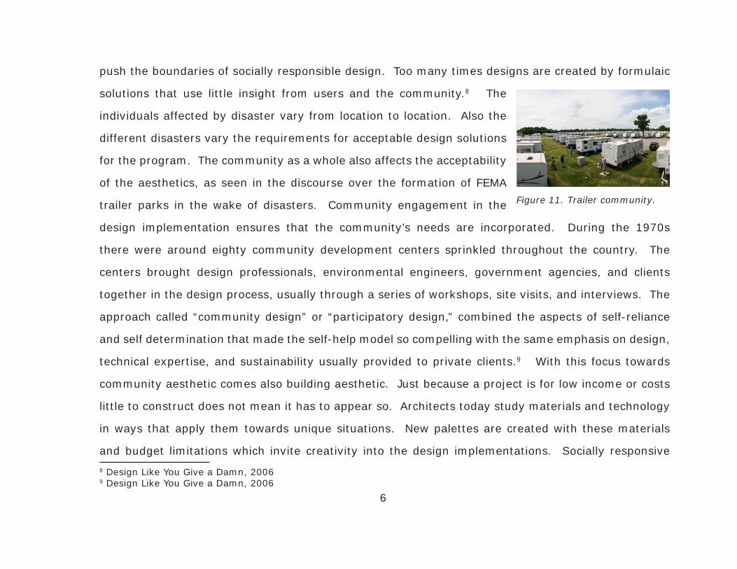
of the aesthetics, as seen in the discourse over the formation of FEMA
trailer parks in the wake of disasters. Community engagement in the
design implementation ensures that the community’s needs are incorporated. During the 1970s
there were around eighty community development centers sprinkled throughout the country. The
centers brought design professionals, environmental engineers, government agencies, and clients
together in the design process, usually through a series of workshops, site visits, and interviews. The
approach called “community design” or “participatory design,” combined the aspects of self-reliance
and self determination that made the self-help model so compelling with the same emphasis on design,
technical expertise, and sustainability usually provided to private clients.9 With this focus towards
community aesthetic comes also building aesthetic. Just because a project is for low income or costs
little to construct does not mean it has to appear so. Architects today study materials and technology
in ways that apply them towards unique situations. New palettes are created with these materials
and budget limitations which invite creativity into the design implementations. Socially responsive
6
8 Design Like You Give a Damn, 20069 Design Like You Give a Damn, 2006
Figure 11. Trailer community.

architecture relies on the architect to remember the relationship to the
client. Samuel Mockbee exemplifies the relation of the architect to the
client, disregarding the economics of the situation.
With the already present challenges to be efficient and aesthetic
comes the need to be environmentally conscious. Sustainable architecture
today is defined with many terms and variations. Sustainability will
be defined as making conscious ecological decisions in every aspect
of planning, design, construction, and manufacture.10 By making this
conscious effort to assess the “greenness” of a building, many design
implications have to be taken into account. Material selection and use, as
mentioned earlier in the efficiency of the construction, also contributes to
the sustainability of the project. One third of all waste in landfills comes
from building construction and demolition. Energy consumption from the
running of buildings accounts for the larger source of energy use in the
world today and therefore serves as a necessary study for all applications
of architecture. Consumption of energy can be limited and offset by designing passive heating and
cooling, use of daylight systems, and actively collecting the sun’s rays with photovoltaic systems.
With the nature of the project temporary, it requires the design to incorporate better means of waste
7
10 Stang & Hawthorne, 2005
Figure 12. Samuel Mockbee architecture.
Figure 13. Passive design.

removal because of the potential that these systems will be inaccessible
because of the context of the site. Technologies have developed to
create sustainable approaches that limit waste accumulation. Also the
conservation of water needs to be implemented to reduce the strain
on the supply source. Grey water technology systems not only reduce
waste but also reuse the water for other uses and can be filtered by
mean of passive treatment. This conscious effort for sustainable design
at every stage leaves a final result open to variation and one that may
not be evident until reached.
Architects throughout the country have designed many similar
projects that follow these same principles and create relief for victims of
disasters. Though many of these designs reflect immediate response,
their concepts can be studied to reflect the mobility of design.11 With
these precedents that exist throughout the world, why were there so
many shortcomings in aid for victims of Hurricane Katrina? One major
problem is the lack of proper legislation describing what specifically
should be used for aid. Federal aid comes in many forms as waivers,
checks, and temporary housing for victims. Further complicating relief
8
11 Siegal, 2008
Figure 14. Grey water system.
Figure 15. Doors prototype.
Figure 16. Push Button House.

operations in disaster situations are the large number of humanitarian
organizations, UN and donor aid agencies, and Red Cross-related
groups. This presents a wonderful challenge: Designing and effectively
implementing a coherent strategy that maximizes the resources of each
organization.12 Bias committees have been formed in past disasters for
distribution of aid such as the Committee of Fifty, a self appointed citizens’
committee designated by President Hoover in the wake of the famous San Francisco earthquake and
fire of 1906. This Committee was convinced that efficiency was the top priority and routinely refused
to be pressured into what they regarded as “inefficient giving.” This resulted in relief that benefitted
business and lacked the responsibility and decency to take care of the needs of the poor and minority
populations.13 Improper planning also contributed to the insufficient aid for victims of hurricane
Katrina. Detailed focus on passing legislation that allows victims to access these properly designed
shelters could have prevented the substandard living qualities found in FEMA trailer communities. The
design implications associated with an understanding of the political nature and selection of projects
by the government opens up new concepts in design. These concepts should be rightfully studied and
presented by the architect because of his/her knowledge of the project. You have already accepted
the responsibility of design and should assist in reaching full fruition of the built form. A typology
that creates responsive design that is efficient, aesthetic, environmentally conscious, and readily
9
12 Natsios, 199713 Hartman & Squires, 2006
Figure 17. Red Cross relief.

implemented requires intensive research that studies precedence in design of temporary structures,
values of the community, emerging technological paradigms, and current policy.
Process
Efficient design renders many architectural implications. How
we discover these implications is the result of exhaustive study.
This research will dive into the study of materials in detail. Material
knowledge will help to provide a building block for the overall design,
beginning the kit of parts mentioned earlier. Not only is the material
important, but the craft of construction serves a great role. Craft
can be seen in the detailing work of shaker boxes and other great
craftsmen of the past. Also analyzing current precedents of small
scale, site assembled vernacular architecture will give insight into the
joinery systems required of this typology. To ensure that the project is
not wasteful during construction and that the deconstruction process
further develops the design, research into companies that instill efficient
manufacturing processes is needed. The IKEA Concept guides the way
IKEA products are designed, manufactured, sold, and assembled. All of these factors contribute to
transforming the IKEA Concept into a reality.14 It is important to note that this research is to develop
10
14 IKEA Concept, 2009
Figure 18. Manufacturing industry.
Figure 19. IKEA directions.

efficient standards for manufacture of the project and should not remove the importance of the client,
architect relationship. Variation will be implemented to prevent the creation of a stale architecture
that is merely replicated. These manufacturing companies provide important knowledge that reflects
the quality control and cost efficiency of premade construction techniques.
When trying to design for the aesthetic of the client and the community the best method of data
collection is direct interviews with the parties involved. Samuel Mockbee created a strong relation to
the client’s needs in the design. He said to “love your neighbor as yourself. This is the most important
thing because nothing else matters. In doing so, an architect will act on a foundation of decency
which can be built upon. Go above and beyond the call of a ‘smoothly
functioning conscious’; help those who aren’t likely to help you in return,
and do so even if nobody is watching!” The Rural Studio, under the
direction of Samuel Mockbee, provided a strong dialogue with the client
that allowed a free flow of information and a vast wealth of knowledge
provided by the client on the soul of the project. Study of a transitional
community in Sri Lanka also provides insight into the use of a series of workshops that collaborate
with the families and the local government to design safe shelters that enable them to carry on with
everyday tasks and a return to normalcy. This resulted in a design that met government approval and
the displaced families’ needs.15
1115 Design Like You Give a Damn, 2006
Figure 20. Transitional house.

Researching for the development of an environmentally conscious will study the emerging
technology being invented by engineers and designers. Ever progressing techniques of energy
conservation are being designed because of the strong influence to help preserve the nature we live
in. Quantitative analysis of the recordings of electrical consumption will be assessed along with the
qualitative analysis of living conditions within the structure. The precedence being set by current
sustainable architecture is ever present in society with recent booms in
this area of interest. Because the quality of life is so important, choosing
the correct finishes on the interior will determine the air quality of the
enveloped space. Also a lot of energy is used in the production of materials,
embodied energy, which can be limited by choosing materials that need
little fabrication or are recycled from previous architectural works in the
area. Solar technology has advanced exponentially with a great number of materials for insulation
of the heat as well as direct energy production by the collection of the sun’s rays with photovoltaic.
The quantitative data on this subject is very comprehensive. Close investigation occurs when the use
of one technology is used in another way within the building.16 For example, using photovoltaics to
collect sun rays for energy production can also serve as a shading device that passively cools an area
within the building. Suburban sprawl, with its low-density, low-rise development, has turned out to
be one of mankind’s more harmful intrusions on the environment. New movements have raised valid
12
16 Schittich, 2003
Figure 21. Photovoltaic array.

concerns about suburban sprawl and neighborhoods that are scaled for cars rather than people. The
detailing of shading devices is also very complex and variable within the design. All these analyses
work collaboratively to help implement environmentally conscious design.
To implement design that coordinates with written legislature to enable the use of the project
in these situations will depend on the intensive study of current regulations set by federal and non-
government organizations. Limits on cost, building code restriction, and qualification standards
are all set by organizations in HUD and FEMA. HUD is the US Department of Housing and Urban
Development and was founded in 1965 to develop and execute policy on housing and cities. FEMA is
the Federal Emergency Management Association and deals directly with federal aid provided to areas
of disaster, declared by the President. A greater understanding of the guidelines set by these and
other organizations at the beginning of the design process will provide a basis for argument for how
this project will help benefit victims and actually be implemented.
Development
This new typology for victims of catastrophe will be efficient, aesthetically acceptable,
environmentally conscious, and ready for implementation into the current framework of society.
The design project will be developed through a series of models and a full scale production of one
unit. It will be selected for a specific site, in a recent area declared as a natural disaster area, for
study into the efficiency of the structure. A client or set of clients will be selected to provide insight
into the needs of that displaced person or family. Not only are the functional needs of the user
13

important, but also a sense of place in society and a feeling of home are necessary components
of the design. Further analysis of the site will include its macro and micro location, climate,
surrounding influences, history, access, views, topography, ecology, and hazards in the area that
pose a concern. Along with a need to understand the context of the area is the need to develop a
detailed program and problem statement for defining the issues of the project. Next is to develop
goals and objectives, or benchmarks, along the way that will help to guide the design and solve the
problems defined above. A concept for the project will reflect inherent qualities found in the context
of the site and the client. Finally the solution will be implemented to fulfill all these requirements
previously set. This method of design is a constructive approach that uses these classical problem
solving techniques, its elements, sequencing, and feedback monitoring processes to create a built
form that is more than just a solution to the problem.
14

CASE STUDIES
definition: an empirical inquiry that investigates a contemporary phenomenon within its real-life
context, especially when the boundaries between phenomenon and context are not clearly evident
Three projects were chosen at the beginning to investigate heavily into the framework and design of
the project. These case studies follow a set of design criteria that were established before deciding
on investigation of the case. The criteria were narrowed down from a list to include: programmatic
space and variability, construction and assembly, mobility, and materiality.
Programmatic Space and Variability: This refers to the floor plan of the building. How this plan
relates the number of individuals that are housed in the structure. It also refers to the ability of the
structure to be varied in size and orientation.
Construction and Assembly: This criterion refers to the projects’ methods of construction. Are they
built prefab in a factory off site and assembled on site or are they constructed on site in a traditional
matter?
15
Mobility: This refers to the projects’ ease of changing its location once placed on site. Is it able to
be moved or shifted once located in the certain scenario?
Materiality: This refers to the materials that are used in the construction of the project. Are they
traditional materials or are they new age materials that are being used for the first time?
16

17
Disaster Housing Pilot Project - FEMAIn November of 2008 the Department of Homeland Security, Federal Emergency Management Agency, Disaster Assistance Section issued a solicitation in order to award up to five (5) contracts for the manufacture of temporary housing units, specifically travel trailer models. The travel trailers shall be built to meet FEMA’s performance specifications, which include requirements to eliminate the use of formaldehyde emitting materials such that the unoccupied indoor air quality tests below .016 ppm.
Programmatic Space and Variability The results for the bid generated many designs with 5 being selected by FEMA. These designs follow the strict guidelines and vary in size from 311ft2 to 640ft2 of interior space. The largest project, the Heston – Modular, features 2 bedrooms, 1 bath, and a kitchen/dining area.
Figure 22. Disaster Pilot Project interior and exterior photos.
Figure 23. Heston Modular example plan.
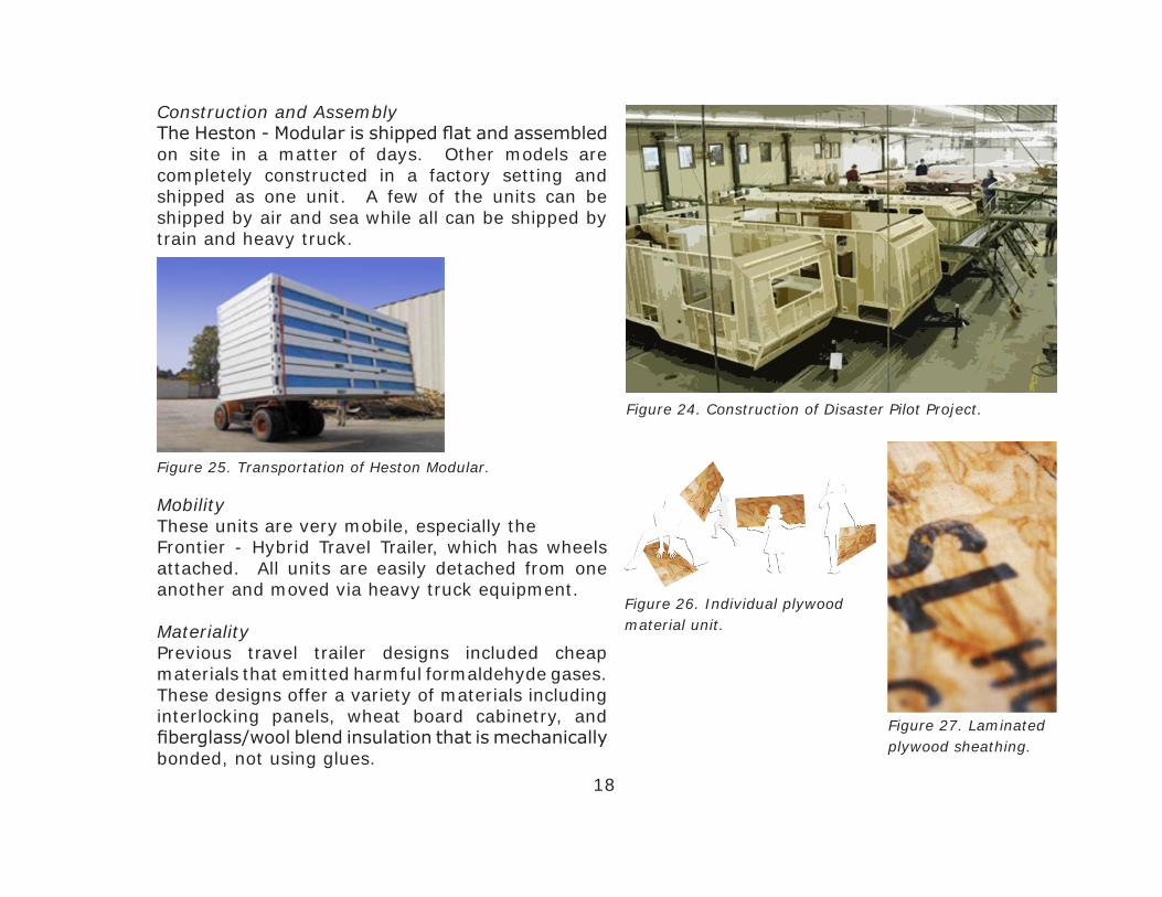
Construction and Assembly The Heston - Modular is shipped flat and assembled on site in a matter of days. Other models are completely constructed in a factory setting and shipped as one unit. A few of the units can be shipped by air and sea while all can be shipped by train and heavy truck.
18
Figure 24. Construction of Disaster Pilot Project.
Mobility These units are very mobile, especially the Frontier - Hybrid Travel Trailer, which has wheels attached. All units are easily detached from one another and moved via heavy truck equipment.
Materiality Previous travel trailer designs included cheap materials that emitted harmful formaldehyde gases. These designs offer a variety of materials including interlocking panels, wheat board cabinetry, and fiberglass/wool blend insulation that is mechanically bonded, not using glues.
Figure 25. Transportation of Heston Modular.
Figure 27. Laminated plywood sheathing.
Figure 26. Individual plywood material unit.
19
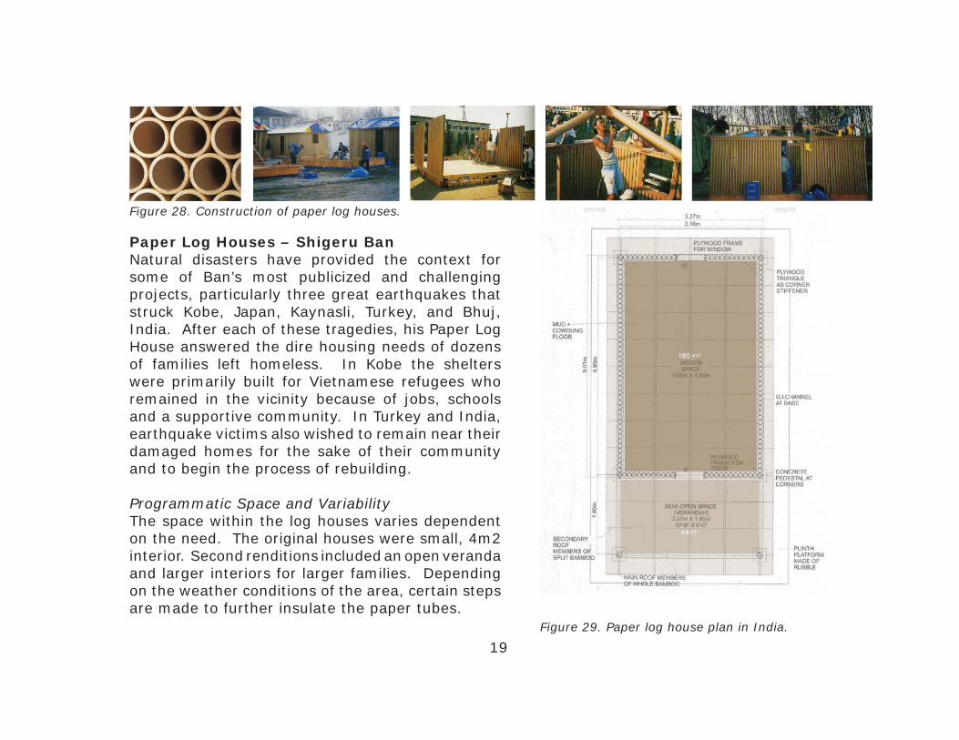
Paper Log Houses – Shigeru BanNatural disasters have provided the context for some of Ban’s most publicized and challenging projects, particularly three great earthquakes that struck Kobe, Japan, Kaynasli, Turkey, and Bhuj, India. After each of these tragedies, his Paper Log House answered the dire housing needs of dozens of families left homeless. In Kobe the shelters were primarily built for Vietnamese refugees who remained in the vicinity because of jobs, schools and a supportive community. In Turkey and India, earthquake victims also wished to remain near their damaged homes for the sake of their community and to begin the process of rebuilding.
Programmatic Space and Variability The space within the log houses varies dependent on the need. The original houses were small, 4m2 interior. Second renditions included an open veranda and larger interiors for larger families. Depending on the weather conditions of the area, certain steps are made to further insulate the paper tubes.
Figure 28. Construction of paper log houses.
Figure 29. Paper log house plan in India.

Construction and Assembly A construction leader is assigned to each house. Prefabricated elements are prepared off-site and trucked on-site the morning of assembly. The first 6 houses are assembled after 8 hours and 21 are built within a month. Since the paper tubes are lightweight, everyone can get involved in assembly process.
Mobility The material is very lightweight but durable and strong which allows for easy transportation of the pieces. Since the tubes are standardized units with a hollow space in the interior, they take up a lot of space when shipping. There are both benefits and disadvantages to the tube.
20
Figure 31. Paper Log House elevation and canopy.
Figure 30. Individual bamboo material unit.
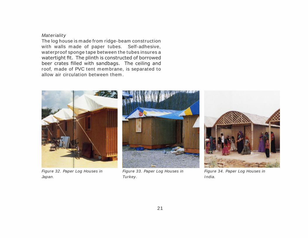
Materiality The log house is made from ridge-beam construction with walls made of paper tubes. Self-adhesive, waterproof sponge tape between the tubes insures a watertight fit. The plinth is constructed of borrowed beer crates filled with sandbags. The ceiling and roof, made of PVC tent membrane, is separated to allow air circulation between them.
Figure 32. Paper Log Houses in Japan.
Figure 33. Paper Log Houses in Turkey.
Figure 34. Paper Log Houses in India.
21

22
Figure 35. Portable house interior and exterior photos.
Figure 37. Portable house elevations.
Portable House – Office of Mobile DesignJennifer Siegal, the founder of OMD, challenges preconceived notions of the trailer park and has created Portable House as a “provocative counterpoint” to the assumptions of the mainstream housing unit. OMD is based in Los Angeles, a city where many buildings are temporary fixtures constructed to serve a limited purpose and then demolished.
Programmatic Space and Variability Central to the Portable Houses is its kitchen and bathroom facility, which also serves as a division between the sleeping area and the lounge. The
Figure 36. Exterior facade of portable house.

compact house can be enlarged when extra space is needed by sliding out and extending the structure containing the lounge area.
Construction and Assembly The houses are factory-made and consequently relatively cheap to buy, however, for the same reason they are also constructed to a higher standard. The basic module steel frame is 12’ x 60’. The home takes 4-8 weeks to construct depending on specs and is trucked fully assembled.
Mobility It is much quicker to build, is capable of relocation, and costs about 15% less than a comparable conventionally built house. On site assembly for the single module ShowHouse took only 2 hours. More complex projects are unlikely to relocate once installed.
Materiality A primary aim for the Portable House is to make the fullest use of sustainable building materials. The interior partitions are made with fiberboard derived from recycled waste paper, the flooring is made from bamboo, Polygal is used in place of glass, and structural wall paneling is used for its added insulation properties.
23
Figure 38. 3-D exploded axonometrics of Portable House.
Figure 39. Transportation of Portable House.
Figure 40. Rendering of Portable House.

Case Study BenefitsEach of these case studies proved to be very beneficial towards the research of new and traditional construction techniques. The most important derivation from each case is the unit established within the encompassing whole. Each case creates some standard of construction and simplifies it to a group of units that are combined to create the greater whole. Discovering these units provides me with the parts to the kit of each project. These parts deal directly with the material makeup of each case and how that material is incorporated into the design.
Disaster Pilot ProjectsThese projects use very standardized construction techniques. The material used within each project is oriented strand board (OSB). This is a very inexpensive material that is made of compressed wood and adhesives. It is a typical material found in temporary mobile housing. The material has some disadvantages because it has to be protected somehow from the elements by another fenestration material. The material is also hidden under the skin of the project, hiding all tectonics of the structure. This diagram shows the unit within the whole and the visual aspects of the material.
Figure 41. Pilot Project Diagram.
24

Paper Log HousesThe material used in these log houses is a standardized tube made of recycled paper. Shigeru Ban is known for using this material throughout the world and is very accustomed to its properties. The tube is very lightweight, easily manageable by one individual, and is combined with others to form the skin and structure of the house. It is a sustainable material also because it composed of recycled tubes from other projects. The tubes are arranged consecutively to form the outer structure of the house. Since the units are rather small they are easy to handle but require lots of labor to assemble the large amount required to form a house. The diagram shows the floor plan reflected in the shape and the unit within the structure.
Portable HouseThis house uses a number of materials but the most unique is the polygal material found in place of the windows. This material is very lightweight and flexible but much stronger than traditional glass with its multi layer system. This material expresses the tectonics by showing the structure between the panels, which is a standardized shape. The diagram shows the unit within the structure and displays is multi layer aspects of the material.
Figure 42. Log House Diagram.
Figure 43. Portable House Diagram.
25

Other StudiestriPOD: a Plug and Play housing system
This housing system is a prefabricated pod-like structure that uses a core center to supply all systems
required to function. A core serving as the spine contains all the mechanical equipment of the building
and serves as the main circulation space. The entire structure is designed with modular widths
allowing for ease of assembly and disassembly of the pod structure. Standardized pods are placed as
needed by the occupants in connections within the central core. The pods can be recycled completely
and used at other sites, allowing families to personalize their home as they need certain spaces. This
study employs the use of complete prefabrication off site and installs these PODS after fabrication.
The pods must meet dimensions of the core leaving little chance for much variation within the unit.
The project benefits from the use of factory made objects preventing the loss of material found at
traditional building site.
Figure 44. Construction of triPOD prefabricated modular system.
Figure 45. Diagram of triPOD.26

ME:LU Modular Expandable Living Unit
This living unit takes advantage of the large amount of shipping containers found throughout the world.
These containers provide a modular unit that is structurally sound within itself and a standardized size.
Not only do they employ green technologies like solar energy and hot water heating, passive heating
and cooling, electrical and water conservation, and recycled materials, but they also distill the design
down to the needs of an individual to live. This utilitarian design provides an attractive solution to the
needs of the community.
27
Figure 46. Perspectives of ME:LU.
Figure 47. Section-perspective of ME:LU.
Figure 48. 3-D rendering of ME:LU.
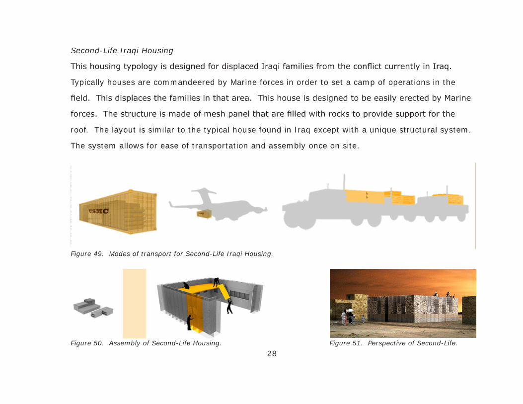
Second-Life Iraqi Housing
This housing typology is designed for displaced Iraqi families from the conflict currently in Iraq.
Typically houses are commandeered by Marine forces in order to set a camp of operations in the
field. This displaces the families in that area. This house is designed to be easily erected by Marine
forces. The structure is made of mesh panel that are filled with rocks to provide support for the
roof. The layout is similar to the typical house found in Iraq except with a unique structural system.
The system allows for ease of transportation and assembly once on site.
28
Figure 49. Modes of transport for Second-Life Iraqi Housing.
Figure 50. Assembly of Second-Life Housing. Figure 51. Perspective of Second-Life.

29
PROGRAMMATIC SPACES
Designing for the programmatic spaces of your structure starts to regulate the limits of the project.
This is the first step to assigning a scope of work to the design and begins to set parameters. These
parameters will define what spaces are included, how much space will be there, and what the user
expects to get out of these spaces. The methods for developing the program is either design based,
knowledge based, agreement based, value based, or a combination of one or all of these. Certain
attributes are assigned to the project that include general properties that are applied to one or a
number of the spaces and start to talk about the quality of space. Once the quality is determined a
scale is set and orientation on the site is determined.

30
Qualities of Space
The quality of the space lists a number of attributes that are assigned to each space and describe its
character. This design strives for certain qualities and they are listed below.
- Allow for interaction between the user and the surrounding community.
- Provide space for gathering of groups or multiple users within the unit.
- Incorporate space for seating and dining for the main occupants of the unit.
- Create a functional, efficient cooking area that allows ease of movement, but does not occupy
too much interior space.
- Provide a bathing area that allows extreme privacy while still being intensely well lit.
- Include a sleeping area that is private and peaceful but also adaptable to multiple users.
- All spaces should be flexible and adaptable to different users.
- Include transitional spaces that define levels of privacy within the structure.
- Provide space for mechanical systems and services so that the structure may function on its
own.

Space Usage and Relationships
To get a better understanding of the spaces a daytime use breakdown was assessed for each space
to determine what spaces were used the most and required the most floor area. I looked at the
space based on a weekday and weekend and compared the hourly usage. During a weekday and
weekend the bedroom space still used the most time, about eight (8) hours per day, though most of
that time is spent asleep. The majority of the other time was spent in the living room, two (2) hours
during a weekday and five (5) hours during a weekend day. The porch was the 3rd most occupied
space, depending on the family style and weather, and the living and dining areas usually equaled
each other comparatively. Obviously hours were higher during weekends because of lack of work
on those days. Both on weekdays and weekends more hours were spent at home than not. The
table below shows a comparison of the hourly usage of each space to one another during the week
and weekend.
31Figure 52. Daytime Usage Breakdown.

Below is a list of associations found in each room that describes the atmosphere that would hopefully
be found in that space. They are listed in hierarchical order from most time spent to least time
spent in each room.
Bedroom – quiet, calm, relaxed, tranquil, private
Living/Porch – very public, loud, exciting, bright
Dining – interactive, semi-public, conversational
Kitchen – workable, functional, efficient
Bathroom – very private, very light, sedate, exclusive
Service – hidden, protected, restricted
32
Figure 53. Diagram of spaces with associations.

Though some rooms reflected high hourly usage, those rooms do not always accommodate for
the most people at once. These numbers vary depending on the associations with those rooms.
Rooms that are very private tend to accommodate only a few individuals even though those people
occupy those rooms the most hours. The bedroom used the most hours during the day and only
accommodates a couple people. The living area accommodates the most individuals. The bedroom,
porch, and dining areas all hold the same amount of people and depend on the number of individuals
the residence houses. The table below lists the number of people each room would accommodate.
33
Figure 54. Maximum occucpancy level for each room.
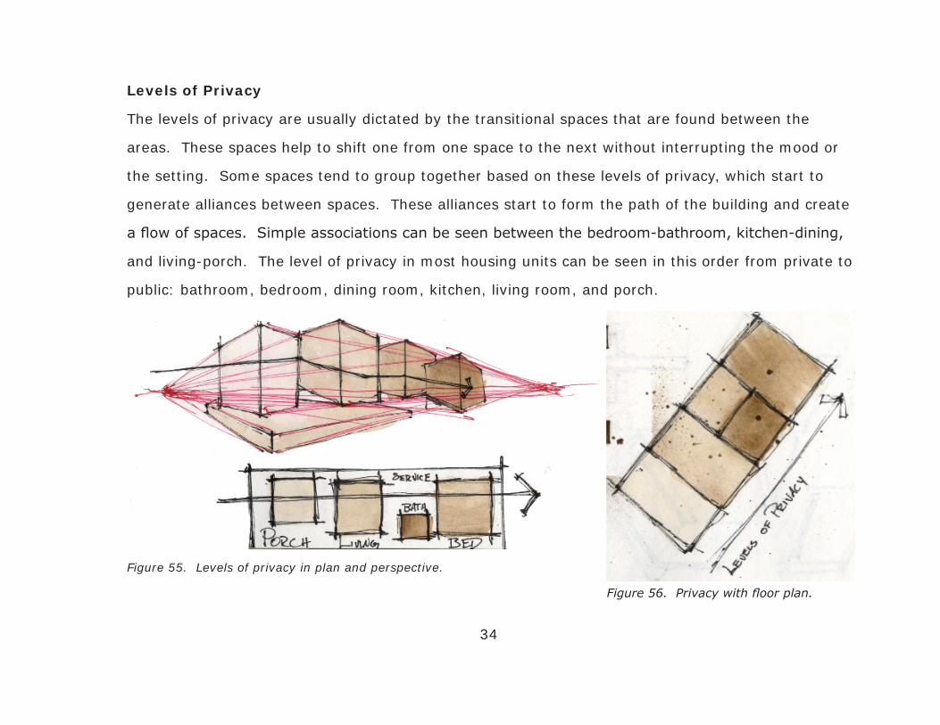
Levels of Privacy
The levels of privacy are usually dictated by the transitional spaces that are found between the
areas. These spaces help to shift one from one space to the next without interrupting the mood or
the setting. Some spaces tend to group together based on these levels of privacy, which start to
generate alliances between spaces. These alliances start to form the path of the building and create
a flow of spaces. Simple associations can be seen between the bedroom-bathroom, kitchen-dining,
and living-porch. The level of privacy in most housing units can be seen in this order from private to
public: bathroom, bedroom, dining room, kitchen, living room, and porch.
34
Figure 55. Levels of privacy in plan and perspective.
Figure 56. Privacy with floor plan.

35
Figure 57. Early groupings of spaces with one another.
36
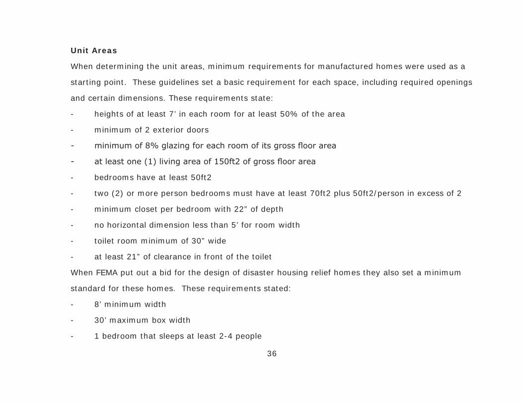
Unit Areas
When determining the unit areas, minimum requirements for manufactured homes were used as a
starting point. These guidelines set a basic requirement for each space, including required openings
and certain dimensions. These requirements state:
- heights of at least 7’ in each room for at least 50% of the area
- minimum of 2 exterior doors
- minimum of 8% glazing for each room of its gross floor area
- at least one (1) living area of 150ft2 of gross floor area
- bedrooms have at least 50ft2
- two (2) or more person bedrooms must have at least 70ft2 plus 50ft2/person in excess of 2
- minimum closet per bedroom with 22” of depth
- no horizontal dimension less than 5’ for room width
- toilet room minimum of 30” wide
- at least 21” of clearance in front of the toilet
When FEMA put out a bid for the design of disaster housing relief homes they also set a minimum
standard for these homes. These requirements stated:
- 8’ minimum width
- 30’ maximum box width
- 1 bedroom that sleeps at least 2-4 people
- 1 bathroom
- 14 cubic foot (c.f.) refrigerator, electric oven/cooktop range
- furnace, rooftop A/C, microwave
- 20 gallon water heater
- living room with at least 70ft2
- kitchen with at least 20ft2
- bathroom with at least 20ft2
- bedroom with at least 35ft2
- estimated total of around 250ft2
These guidelines help to provide a base starting point for determining the floor areas of the different
spaces. In order to provide adequate space for different family sizes, it was determined that 3
different unit sizes would be designed and distributed based on family size and occupancy levels.
Another contributing factor of the floor dimensions is the standard width of a trailer on an 18-
wheeler truck. Since these units will be delivered to residents in their neighborhood, a key design
aspect is that they fit on a standard truck. All these room dimensions were based on that width.
Below is a list of the 3 unit sizes with their associated room sizes for each. The diagram shows the
relationship between the 3 unit areas. Unit B is about 50% larger than Unit A and Unit C is more
than two (2) times the size of Unit A.
37

38
Figure 59. Ratio of Unit Areas to one another.
Figure 58. Space Areas within Unit B.
Figure 60. Comparison of Unit Areas.

SCENARIO ANALYSIS
When determining the site for this design normal conditions do not face the situation. Traditionally
designs are focused around an already predetermined site that is selected by either the architect
or the client. Since this design is based on the occurrence of a natural disaster, the site could
potentially be anywhere in the world.
39
Site Selection
Due to its abundance of disaster-prone areas the
United States will be the site or focus area of this
transitional unit. Throughout the US areas have
been hit heavily by a number of different natural
disasters mainly including wildfires, floods,
tornadoes, earthquakes, and hurricanes. Figure 61. Diagram of sites US wide.

40
Because of my familiarity with the state of Florida and its constant occurrence of natural disasters,
it will be used as the secondary site for code enforcement of the design. Since this design is for
disaster preparation and mitigation the Tampa Bay region will be used as the primary site because
it has yet been hit by a large disaster in recent years. Specific sites throughout Florida were chosen
as precedent areas that had already been affected by disaster in past years. Certain site selection
criteria are used in determining the appropriate study sites for this transitional unit. These criteria
include:
- middle to low class neighborhood
- history of natural disaster occurrence
- high density of homes in neighborhood
- variation of lot size and orientation
- proximity to water
- relation to woodland areas
- elevation and flood zone category
41
In recent months the state of Florida has experienced moderate rainfalls, especially in the middle
of the state. These rainfalls were needed desperately in most areas but have proven to be costly
in some counties, especially Volusia County on the East Coast. This county has seen water levels
above four (4) feet in most areas for the past few weeks in May. It is in part due to its proximity to
water but also because it is in the lowest category of elevation which is very prone to flood. Many
residents have been displaced during this time to local shelters in the area. This is a typical example
of flood in the state and affects thousands each year.
The last major wildfire to affect Florida was in 1999 when one destroyed a number of homes in Port
St. Lucie, FL. The wildfire started from a small brush fire that quickly spread because of high winds.
All in all the fire destroyed over a dozen homes and 2,400 acres of land. Another contributing factor
to the devastation was the lack of adequate fire hydrants in the neighborhood. This area is a very
dense neighborhood with lots of trees, located close to the wooded areas on Gaitland Boulevard.
In 2004 hurricane Charley struck the southwest coast of Florida near Port Charlotte, FL. The area
was devastated by the category 4 hurricane, the largest to hit the state since hurricane Andrew
struck 12 years earlier. The hurricane was expected to make landfall further north in Tampa but
changed course suddenly and hit Hardee and DeSoto counties instead. It was a very strong but fast
moving storm; otherwise damage would have been much more severe.

42
Figure 62. Diagram of natural disasters throughout Florida.

43
Flood Scenario
An area in Tampa Bay that is very prone to flood is a neighborhood called Shore Acres. Located
on the Tampa Bay in Pinellas County this neighborhood sees high levels of water every time any
moderate level of rain falls. The area varies in property value from high end to moderate income.
The very low elevation is cause for much of the flooding and proximity to the bay. Storm drains
often flood when high tide rises. This area sees constant flooding is a prime example for a flood
scenario to take place.
Figure 63. Site research for flood scenario.
Figure 64. Map of flood scenario.
44
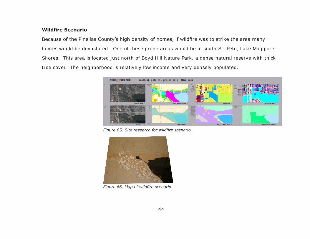
Wildfire Scenario
Because of the Pinellas County’s high density of homes, if wildfire was to strike the area many
homes would be devastated. One of these prone areas would be in south St. Pete, Lake Maggiore
Shores. This area is located just north of Boyd Hill Nature Park, a dense natural reserve with thick
tree cover. The neighborhood is relatively low income and very densely populated.
Figure 65. Site research for wildfire scenario.
Figure 66. Map of wildfire scenario.
45
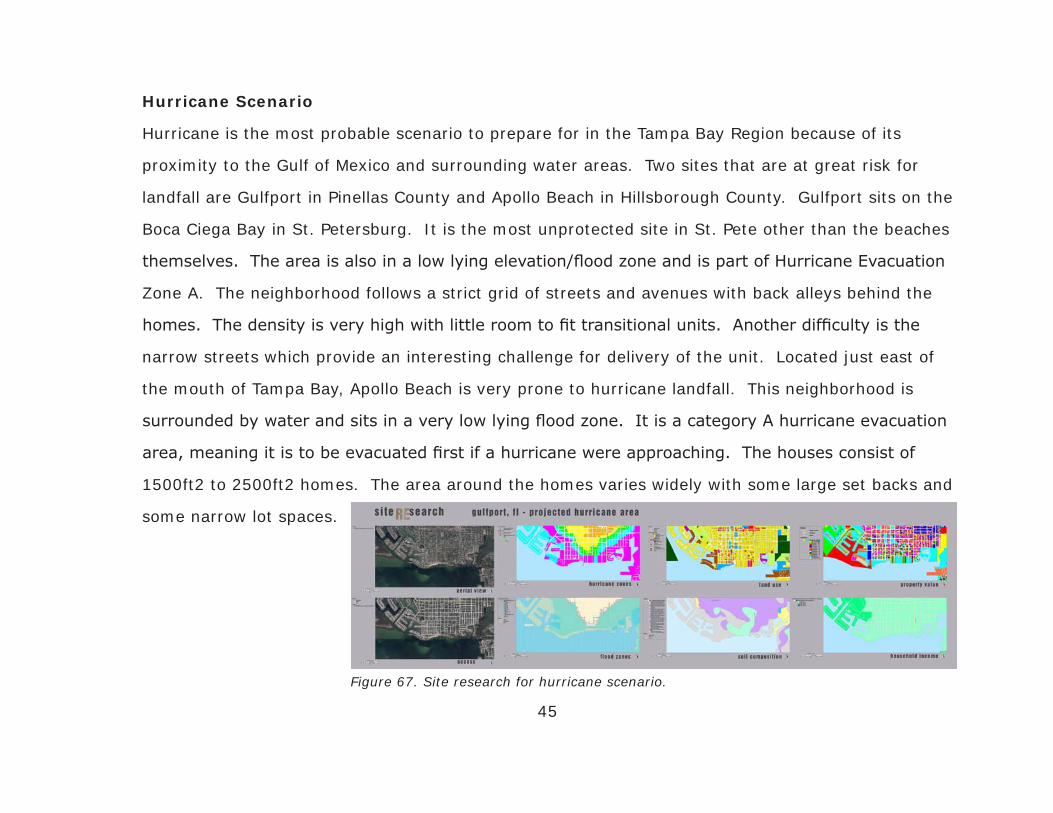
Hurricane Scenario
Hurricane is the most probable scenario to prepare for in the Tampa Bay Region because of its
proximity to the Gulf of Mexico and surrounding water areas. Two sites that are at great risk for
landfall are Gulfport in Pinellas County and Apollo Beach in Hillsborough County. Gulfport sits on the
Boca Ciega Bay in St. Petersburg. It is the most unprotected site in St. Pete other than the beaches
themselves. The area is also in a low lying elevation/flood zone and is part of Hurricane Evacuation
Zone A. The neighborhood follows a strict grid of streets and avenues with back alleys behind the
homes. The density is very high with little room to fit transitional units. Another difficulty is the
narrow streets which provide an interesting challenge for delivery of the unit. Located just east of
the mouth of Tampa Bay, Apollo Beach is very prone to hurricane landfall. This neighborhood is
surrounded by water and sits in a very low lying flood zone. It is a category A hurricane evacuation
area, meaning it is to be evacuated first if a hurricane were approaching. The houses consist of
1500ft2 to 2500ft2 homes. The area around the homes varies widely with some large set backs and
some narrow lot spaces.
Figure 67. Site research for hurricane scenario.

46
Figure 68. Map of Gulfport hurricane scenario. Figure 69. Map of Apollo Beach hurricane scenario.
47
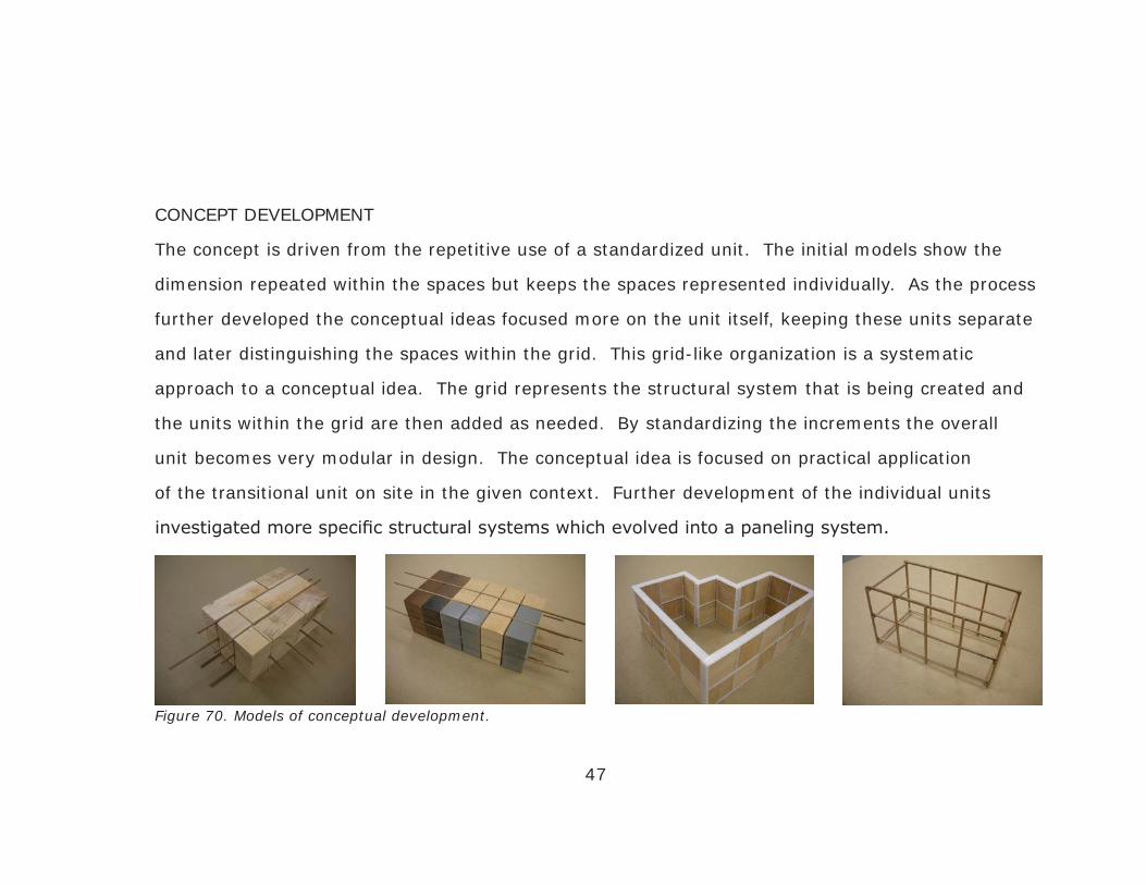
CONCEPT DEVELOPMENT
The concept is driven from the repetitive use of a standardized unit. The initial models show the
dimension repeated within the spaces but keeps the spaces represented individually. As the process
further developed the conceptual ideas focused more on the unit itself, keeping these units separate
and later distinguishing the spaces within the grid. This grid-like organization is a systematic
approach to a conceptual idea. The grid represents the structural system that is being created and
the units within the grid are then added as needed. By standardizing the increments the overall
unit becomes very modular in design. The conceptual idea is focused on practical application
of the transitional unit on site in the given context. Further development of the individual units
investigated more specific structural systems which evolved into a paneling system.
Figure 70. Models of conceptual development.

48
CONCEPTUAL SCHEMATICS
Further evolution of the concept led to variation in size of each unit. Base knowledge of a structural
systems and SIP (structural insulated panel) systems led to the development of a 4’ x 4’ grid. This
size was determined to be an adequate size for 1-2 individuals to easily handle and assemble on
site. This new grid produced new unit areas that followed this standard. These areas include: Unit
A – 288ft2, Unit B – 432ft2, Unit C – 624ft2. The structural system is comprised of aluminum
columns and beams. These members allow easy assembly of the structure. They are lightweight,
stronger than conventional building technologies, and easily connect with one another in any
direction. The structure is modular and allows customization on site.
Figure 71. Detail of structural member with SIP panel.
Figure 72. 3-D detail of structural system.

49
Investigation into adaptablility of the unit shows variation capabilities of Unit B on a number of sites.
Seven (7) variation were adapted to show this customization on site. Further development shows
room orientation within each unit and starts to break down the paneling system into standardized 4’
x 8’ sections. When exploded 3-dimensionally the structural system starts to expose walls, floors,
and ceiling conditions.
Figure 73. Seven variations of unit B.
50
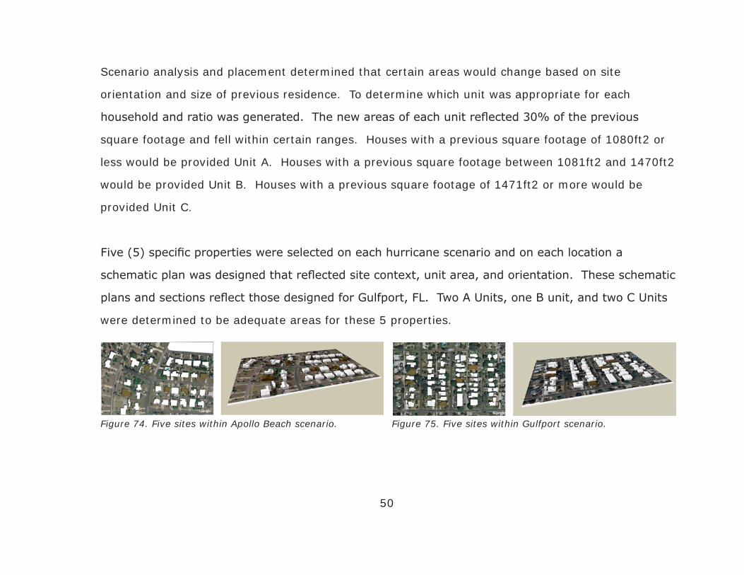
Scenario analysis and placement determined that certain areas would change based on site
orientation and size of previous residence. To determine which unit was appropriate for each
household and ratio was generated. The new areas of each unit reflected 30% of the previous
square footage and fell within certain ranges. Houses with a previous square footage of 1080ft2 or
less would be provided Unit A. Houses with a previous square footage between 1081ft2 and 1470ft2
would be provided Unit B. Houses with a previous square footage of 1471ft2 or more would be
provided Unit C.
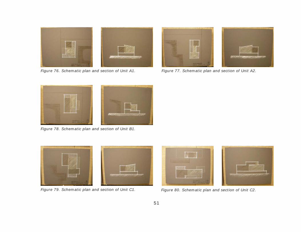
Five (5) specific properties were selected on each hurricane scenario and on each location a
schematic plan was designed that reflected site context, unit area, and orientation. These schematic
plans and sections reflect those designed for Gulfport, FL. Two A Units, one B unit, and two C Units
were determined to be adequate areas for these 5 properties.
Figure 74. Five sites within Apollo Beach scenario. Figure 75. Five sites within Gulfport scenario.
51
Figure 76. Schematic plan and section of Unit A1. Figure 77. Schematic plan and section of Unit A2.
Figure 78. Schematic plan and section of Unit B1.
Figure 79. Schematic plan and section of Unit C1. Figure 80. Schematic plan and section of Unit C2.

52
DESIGN DEVELOPMENT
Initial schematic design looked at the scenario present in each site and reacted to found attributes.
To further the development of the design a set of criteria would have to be written that would drive
the shaping of the unit. These principles would also begin to define who, specifically, would be
provided with assistance and when it would be provided. Defining the time period where transitional
housing fell in the overall situation is important.

Figure 81. Disaster Timeline. 53
Disaster Timeline
Current professionals working for the Task Force on Disaster Planning in Hillsborough County have
estimated a time of 3-5 years for victims to recover from a natural disaster. This diagram shows the
breakdown of a natural disaster, making sure to point out when the transitional housing unit is to
be used. The timeline is separated into 4 sections: the disaster, emergency response, transitional
housing, and recovery. The two paths that run across the diagram are those associated with the
ReLife transitional housing unit and that of FEMA current strategies. It is important to point out that
54
the time when the ReLife Unit is used is after the American Red Cross or similar organization has
provided immediate disaster response to the area. Most likely power and other utilities would have
been re-established by then and plans would be started for recovery. The unit is used during the
extended period where victims are starting to rebuild there previous homes.
Principles of Design
Defining a set of criteria for design helps establish a starting point that can be built upon throughout
the process. This set of criteria guides the development of the unit, and clearly delineates who the
unit is for and what it will include. Earlier research started to define these principles. The unit is
designed for single family homes, not multi-family disaster housing and not emergency housing but
transitional housing. It also designed to be efficient, on site, adaptable, environmentally conscious,
and aesthetically pleasing. These criteria were established very early in the design process and have
evolved throughout. The ability to be on site of the previous home allows it to be either next to the
damaged house or replacing the totally destroyed home. The adaptability of the unit is key to its
design; allowing to fit any site, user customization, varying in size for families, and varying in terms
of destruction. The units adaptability also provides space for systems that allow the unit to function
independent of city utilities if the need arises. The efficiency of the unit is its ability to be easily
shipped to the site and assembled.

55
Efficient Shipping
Using a SIP panel kit of parts allows the ease of stacking units
inside of a shipping container. Multiples of these units can be
shipped at once providing assistance for more than one family
at a time. The unit to the right is Unit A which can easily fit
3 sets of units within one shipping container. The size of the
panel also makes it easy for individuals to load/unload them.
A standard shipping container dimensions are 39’5”L x 7’8”W
x 7’10”H, inside dimensions. The floor area is about 300ft2
and volume is 2390ft3. If Unit C, the largest unit, was stacked
its size would be 25’L x 7’6”W x 7’H with a floor coverage of
187.5ft2 and volume of 1312ft3. This unit size unfolds and
assembles to 624ft2 of interior space. One container can
almost hold two Unit C’s which would unfold to shelter 1248ft2.
Popular designs today use shipping containers as shelters. If
this was the case one container would only shelter 300ft2 of
space when you could ship stack-able units and shelter 4 times
the that amount of space of pre-assembled units.
Figure 82. Unit A Panels Stacked.
Figure 83. Unit Stacked in Shipping Container.

56
Connection to the Ground
Using pre-cast concrete piles allow for easy assembly on site.
The piles also allow the unit to adapt to any site attributes
found. Installation of the piles require little work with an
auger drill that is easily manageable by two individuals. The
spun piles come in standard sizes and are simply placed in the
hole that is formed by the auger bit.
The modular housing system supplies ground plate
connections that are easily attached to the installed concrete
piles. The extruded aluminum supports slip over the ground
plate and bolt into the sides of the post. This system creates
a strong connection to the ground, linking the entire structure
with the earth preventing any uplift that could be foreseen in
hurricane prone areas. It also creates a strong base for the
entire structure to help prevent uneven settling over time.
Figure 84. Auger Drill.
Figure 86. Footing Cross-Section
Figure 85. Footing Assembly.

57
SPECIFIC SITE ATTRIBUTES AND DESIGN
Narrowing down the scenarios to design for a hurricane seemed to be the most important decision
to properly prepare the state of Florida. The two sites chosen were Gulfport and Apollo Beach,
both very prone areas for hurricane landfall. Within each of these scenarios 3 sites were chosen for
study, developing attributes that varied to show the adaptability of the ReLife Transitional Housing
Unit. These sites varied in size, foundation, orientation, and destruction. The main difference
between these two selections was the density found in the neighborhood. Gulfport is located in St.
Petersburg and because of this its streets are smaller and the houses are situated on smaller lots,
closer to one another. Apollo Beach on the other hand is located in a suburban neighborhood with
larger streets and space between the homes.

Figure 87. Gulfport Site Graphic.
58
Gulfport Site Attributes
A set of statistics are set for each site in order to regulate the
design. By creating specific scenarios, the unit can be design
to adapt to any and all situations. The house were selected
based on size, foundation and construction, and year built.
Each house was given a hypothetical amount of damage and
from that the design was determined. Figure 88. Gulfport Site Model.

Gulfport House 1
Foundation: Continuous Footing
Floor System: Slab on Grade
Exterior Wall: Stucco
Year Built: 1950 Living Area Ft2: 1791ft2
Minor damage, Temporary Unit C built next to home.
59
Figure 89. Gulfport House 1.
Figure 90. Gulfport House 2.
Figure 91. Gulfport House 1.
Gulfport House 2
Foundation: Continuous Footing
Floor System: Pier and Beam
Exterior Wall: Frame/Custom Wood
Year Built: 1938 Living Area Ft2: 1313ft2
Minor damage, Temporary Unit B built next to home.
Gulfport House 3
Foundation: Continuous Footing
Floor System: Slab on Grade
Exterior Wall: Concrete Block
Year Built: 1957 Living Area Ft2: 923ft2
Total destruction, Permanent Unit A built on existing slab.

60
Gulfport Unit Designs
Gulfport Unit 1
The initial design of unit 1 was completely driven by the
structural system and layout on site. Two large bedrooms
flanked the living space. The secondary design utilized 3
bedrooms. The spaces also began to push/pull the outside
facade of the building and create a more interesting aesthetic.
Using the tatami floor plan design, the living space became
more harmonious.
Figure 92. Unit 1 Initial Design. Figure 93. Unit 1 Initial Plan.
Figure 96. Unit 1 Secondary Design. Figure 95. Unit 1 Secondary Plan.
Figure 94. Unit 1 Initial Model.
Figure 97. Unit 1 Secondary Model.

61
Gulfport Unit 2
Like that of unit 1, unit 2 lacked aesthetics when initially
designed. The plan and section were completely restricted by
the rigid structural system being used. After rethinking the
entire design and working with facades that push and pull on
one another, the overall design evolved into the secondary
design.
Figure 98. Unit 2 Initial Design. Figure 99. Unit 2 Initial Plan.
Figure 102. Unit 2 Secondary Design. Figure 101. Unit 2 Secondary Plan.
Figure 100. Unit 2 Initial Model.
Figure 103. Unit 2 Secondary Model.

62
Gulfport Unit 3
Unit 3 differed a lot in size tothe rest and creativity was
enlightened on this design because of those small size
restrictions. Initially the design was very simple but
unfortunately boring. The secondary design looked at showing
signifigance to the entrance and created a lateral partii within
the floor plan that drew the eye across the length of the unit.
Spaces were organized along this datum, connecting all of them
together.
Figure 104. Unit 3 Initial Design. Figure 105. Unit 3 Initial Plan.
Figure 108. Unit 3 Secondary Design. Figure 107. Unit 3 Secondary Plan.
Figure 106. Unit 3 Initial Model.
Figure 109. Unit 3 Secondary Model.

Figure 110. Apollo Beach Site Graphic.
63
Apollo Beach Site Attributes
A set of statistics are set for each site in order to regulate the
design. By creating specific scenarios, the unit can be design
to adapt to any and all situations. The house were selected
based on size, foundation and construction, and year built.
Each house was given a hypothetical amount of damage and
from that the design was determined. Figure 111. Apollo Beach Site Model.

Apollo Beach House 4
Foundation: Continuous Footing
Floor System: Slab on Grade
Exterior Wall: Concrete Block
Year Built: 1974 Living Area Ft2: 1398ft2
Minor damage, Temporary Unit B built next to home.
64
Figure 112. Apollo Beach 4.
Figure 113. Apollo Beach 5.
Figure 114. Apollo Beach 6.
Apollo Beach House 5
Foundation: Continuous Footing
Floor System: Slab on Grade
Exterior Wall: Concrete Block
Year Built: 1968 Living Area Ft2: 1144ft2
Total destruction, Permanent Unit B built on existing slab.
Apollo Beach House 6
Foundation: Continuous Footing
Floor System: Slab on Grade
Exterior Wall: Concrete Block
Year Built: 1968 Living Area Ft2: 1735ft2
Minor damage, Temporary Unit C built next to home.

65
Apollo Beach Unit Designs
Apollo Beach Unit 4
Initially unit 4 was limited by the small area on the driveway for
building the unit. Looking strictly at the shape and orientation
of this pad, the design was formulated. After rethinking the
design principles the spaces began to react like those of the
previous units, organizing themselves around the central living
space.
Figure 115. Unit 4 Initial Design. Figure 116. Unit 4 Initial Plan.
Figure 119. Unit 4 Secondary Design. Figure 118. Unit 4 Secondary Plan.
Figure 117. Unit 4 Initial Model.
Figure 120. Unit 4 Secondary Model.

66
Apollo Beach Unit 5
Initially unit 5 was interesting because it enclosed the outside
porch space, but the interior did not provide any variation. The
secondary design created interior spaces that changed in ceiling
heights and had lots of variation. It also started to pay close
attention to how the dining space acted as a temporary space,
popping up as needed from the wall.
Figure 121. Unit 5 Initial Design. Figure 122. Unit 5 Initial Plan.
Figure 125. Unit 5 Secondary Design. Figure 124. Unit 5 Secondary Plan.
Figure 123. Unit 5 Initial Model.
Figure 126. Unit 5 Secondary Model.

67
Apollo Beach Unit 6
Unit 6 is another quite large unit that initially provided some
variation within the space, creating two large bedrooms on
two corners of the unit. The secondary design shows an
immense amount of variation in the facade and the open living
and dining space stretches the length of the unit. This unit
especially provides privacy for all the inhabitants with three
separate bedrooms.
Figure 127. Unit 6 Initial Design. Figure 128. Unit 6 Initial Plan.
Figure 131. Unit 6 Secondary Design. Figure 130. Unit 6 Secondary Plan.
Figure 129. Unit 6 Initial Model.
Figure 132. Unit 6 Secondary Model.

68
Sectional Qualities
The section models were created after the
secondary designs to look at the interior
spaces within the unit. Initially the living
space had 12’ high ceilings, the living/dining
space had 8’ high ceilings, and the bedroom
space was 8’ tall interiorly with a 2’ step up
inside. This provided variation in heights that
created interesting feeling within each space,
either enclosure or openness. After defense
of the unit, my committee noted that the unit
needed to remain rather simple for assembly
by non-professionals and it also needed
to give access to all peoples, including the
handicapped. From that the interior spaces
changed, mainly the bedroom space increased
to 10’ high ceilings and the step up was
eliminated. These studies also started to look
at the materials used in the different spaces.
Figure 133. Section Model 1.
Figure 134. Section Model 2.
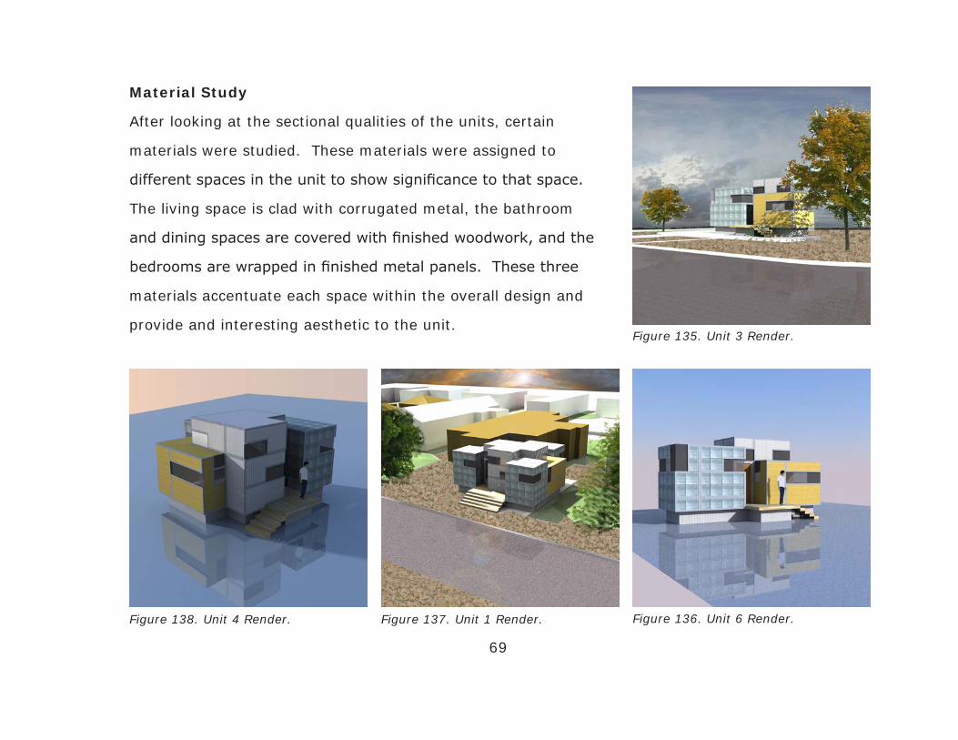
69
Material Study
After looking at the sectional qualities of the units, certain
materials were studied. These materials were assigned to
different spaces in the unit to show significance to that space.
The living space is clad with corrugated metal, the bathroom
and dining spaces are covered with finished woodwork, and the
bedrooms are wrapped in finished metal panels. These three
materials accentuate each space within the overall design and
provide and interesting aesthetic to the unit.Figure 135. Unit 3 Render.
Figure 136. Unit 6 Render.Figure 137. Unit 1 Render.Figure 138. Unit 4 Render.
70
PROCESS OF DESIGNING A UNIT
By combining frames, panels, and doors from the ReLIFE series with energy conserving devices, you
can create exactly the transitional housing unit that fits you and your family’s needs. Alternatively
you can choose different wall, roof, and floor systems and add or remove interior panels as you wish.
Either way, the result is a transitional housing unit that is custom-designed to suit both your site
conditions and the space that you require.
How To Build
Whether you are thinking of designing your own transitional housing unit or buying one of the
existing solutions, there are 3 simple steps to follow
1. Pick your type. Has your home been only partially damaged or is it completely destroyed?
There are selections that are for long-term temporary use, located next to your previous house.
There are also units that are designed to expand as you can afford, eventually replacing your original
home.
2. Choose your size. Your size unit is determined by the previous square footage of your home,
size of your family, and space available on site. The unit is offered in 3 sizes that are roughly 1/3
the size of your original home.
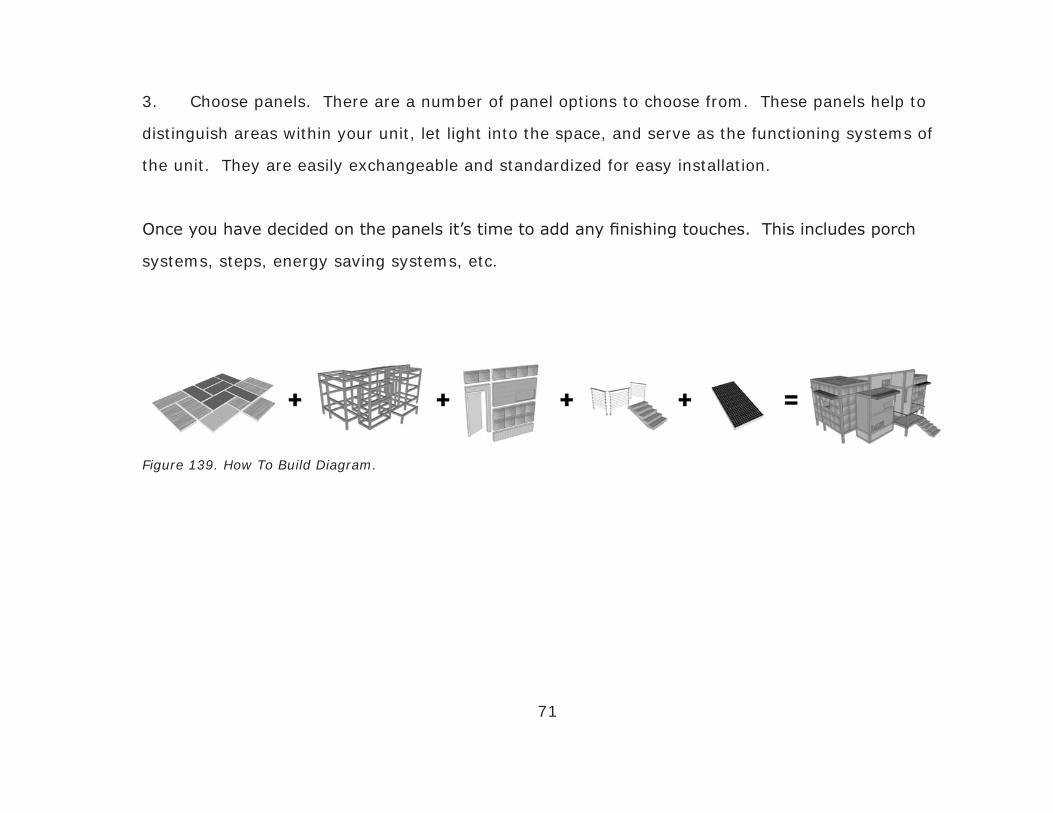
71
Figure 139. How To Build Diagram.
3. Choose panels. There are a number of panel options to choose from. These panels help to
distinguish areas within your unit, let light into the space, and serve as the functioning systems of
the unit. They are easily exchangeable and standardized for easy installation.
Once you have decided on the panels it’s time to add any finishing touches. This includes porch
systems, steps, energy saving systems, etc.

72
How To Choose Type
Below you see the two different types of ReLIFE Housing Unit. The first is temporary, built on site
of the previous home. The other is permanent and is built on the foundation of the previous home.
These units can be designed to fit the site and the foundation, allowing multiple combinations to
occur. Depending on the extent of damage to your home caused by the natural disaster, you will
choose whether the unit will be temporary or remain permanently.
Permanent ReLife Transitional Housing Unit
This unit expands multiple times throughout its
life, eventually covering the entire foundation of
your previous home, replacing your lost house.
Temporary ReLife Transitional Housing Unit
This unit remains one size throughout its use
during the rebuilding of your previous home.
Figure 140. Temporary ReLife Unit. Figure 141. Permanent ReLife Unit.

73
Permanent Floor Plan Expansion
This progression of a unit shows how the permanent ReLIFE Unit adapts to the given foundation and
evolves into a house that fits the old shape of your original home. The designers pay close attention
to the original floor plate and design an expandable unit that resembles the design and floor area of
your original home. Using this system of design provides efficient response when in need and allows
you to remain in your community.
Figure 142. Permanent Unit Stage 1. Figure 143. Permanent Unit Stage 2. Figure 144. Permanent Unit Stage 3.

74
How To Choose Unit Size
Below are the 3 options for size of unit based on the original square footage of your home. These
units are roughly one third of your original home and consist of a living room, dining room/kitchen,
bathroom, and 1-3 bedrooms depending on unit size. These spaces are shown with different panels
and represent the area that would be found in each space. Each panel is 4’ x 8’ and fits easily into
different configurations.
Figure 145. Unit A Spaces. Figure 146. Unit B Spaces. Figure 147. Unit C Spaces.
Unit Size A
Floor Area = 288ft2
For Homes 0ft2 - 1080ft2
1 Bedroom/1Bath
Accommodates up to 2
people.
Unit Size B
Floor Area = 432ft2
For Homes 1081ft2 - 1470ft2
2 Bedroom/1Bath
Accommodates up to 4 people.
Unit Size C
Floor Area = 624ft2
For Homes 1471ft2 - 2400ft2
3 Bedroom/1Bath
Accommodates up to 6 people.

Unit Components
75
Footings
Each unit either attaches to the
existing foundation with metal
plates or attaches to cylindrical
footers that are placed on site.
Living Space
The main public space within
the unit, the living space has
12ft high ceilings and sub-
flooring for water and electrical
utilities.
Bedroom Space
Each bedroom space has roof
extensions that raise the ceiling
height to 10ft. Window shades
help block out summer sun but
allow in winter sun.
Figure 148. Footings. Figure 149. Living Space. Figure 150. Bedroom Space.
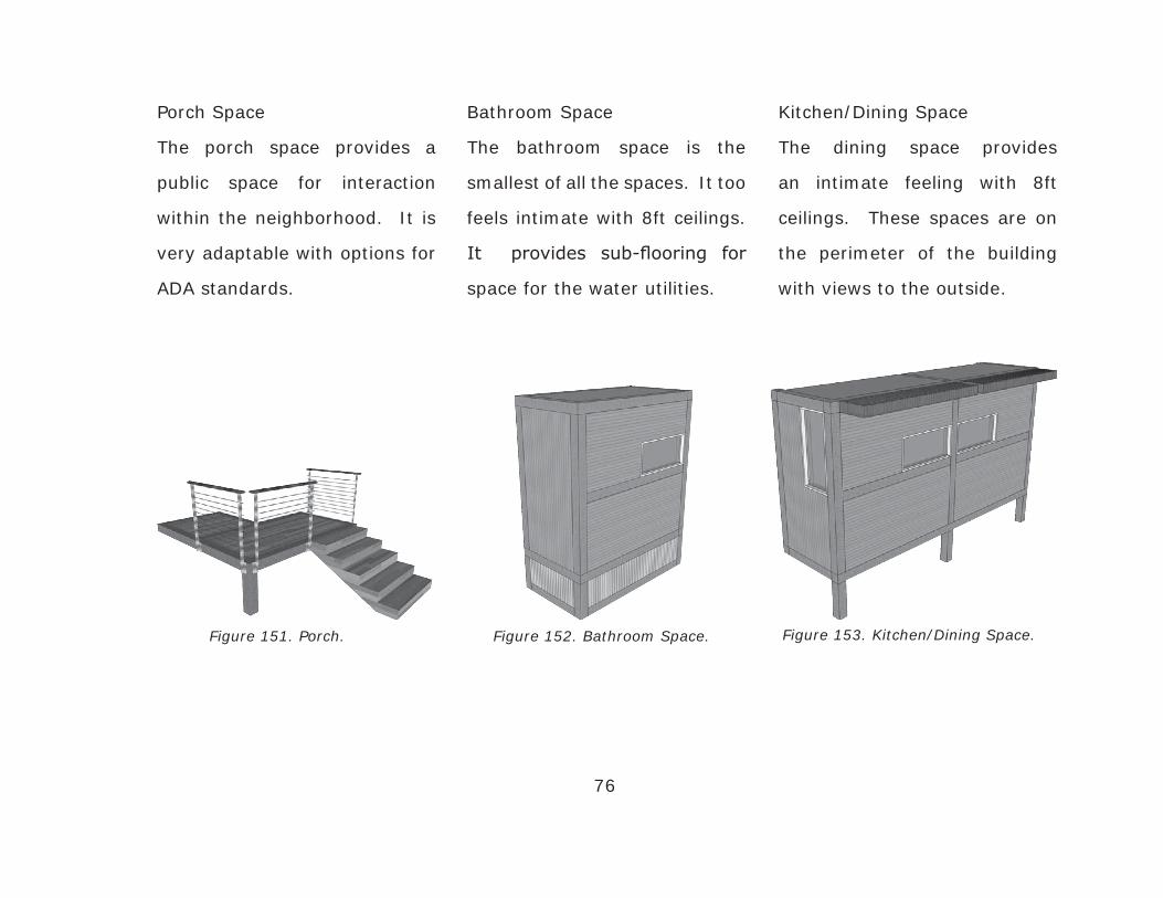
Kitchen/Dining Space
The dining space provides
an intimate feeling with 8ft
ceilings. These spaces are on
the perimeter of the building
with views to the outside.
Bathroom Space
The bathroom space is the
smallest of all the spaces. It too
feels intimate with 8ft ceilings.
It provides sub-flooring for
space for the water utilities.
Porch Space
The porch space provides a
public space for interaction
within the neighborhood. It is
very adaptable with options for
ADA standards.
76
Figure 151. Porch. Figure 152. Bathroom Space. Figure 153. Kitchen/Dining Space.

77
SIP Panel OptionsWindow Wall PanelThis panel can be arranged in any direction providing ample interior light.Dimensions: 8’ x 3’9” x 6”Window Dim.: 4’ x 1’11.5”, with 2” mullionAvailable Surfaces: Corrugated Steel Finished Metal Panel Finished Wood Hardi-Panel Gypsum Interior
Wall PanelThis panel is universal throughout the unit.Dimensions: 8’ x 3’9” x 6”Available Surfaces: Corrugated Steel Finished Metal Panel Finished Wood Hardi-Panel Gypsum Interior
Floor PanelThis panel provides extra support for traffic inside and out of the unit.Dimensions: 8’ x 3’9” x 6”Available Surfaces: Hardwood Flooring Bamboo Flooring Cork Flooring Tile Flooring Glass with HOG Water Storage
Figure 154. Window Wall Panel.
Figure 155. Wall Panel.
Figure 156. Floor Panel.

78
Figure 157. SF-RE Panel.
Figure 158. Door Panel.
Figure 159. Roof/Ceiling Panel.
Sub-Floor/Roof Extension PanelThese panels provide storage for utilities under the unit and also extend ceiling heights in the bedrooms and living room.Dimensions: 8’ x 1’7.5” x 6”Available Surfaces: Corrugated Steel Finished Metal Panel Finished Wood Hardi-Panel Gypsum Interior
Door PanelThese panels provide openings in spaces and can be used interior or exterior, depending on surfaces.Dimensions: 8’ x 3’9” x 6”Door Dim.: 7’ x 3’, with 2” door frameAvailable Surfaces: Corrugated Steel Finished Metal Panel Finished Wood Hardi-Panel Gypsum Interior
Roof/Ceiling PanelThis panel is lightweight for ease of installation above spaces.Dimensions: 8’ x 3’9” x 6”Available Surfaces: Corrugated Steel Finished Metal Panel Finished Wood Photovoltaic Cells Gypsum Interior
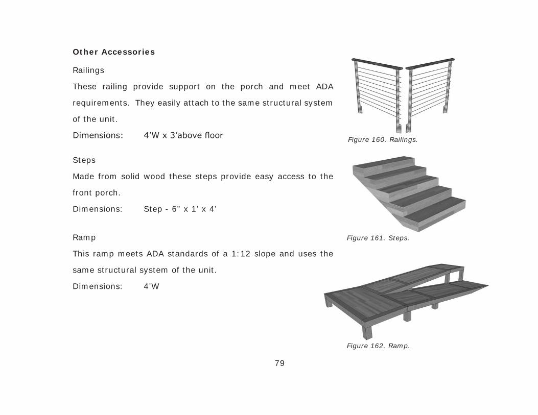
Railings
These railing provide support on the porch and meet ADA
requirements. They easily attach to the same structural system
of the unit.
Dimensions: 4’W x 3’above floor
Steps
Made from solid wood these steps provide easy access to the
front porch.
Dimensions: Step - 6” x 1’ x 4’
Ramp
This ramp meets ADA standards of a 1:12 slope and uses the
same structural system of the unit.
Dimensions: 4’W
79
Other Accessories
Figure 160. Railings.
Figure 161. Steps.
Figure 162. Ramp.
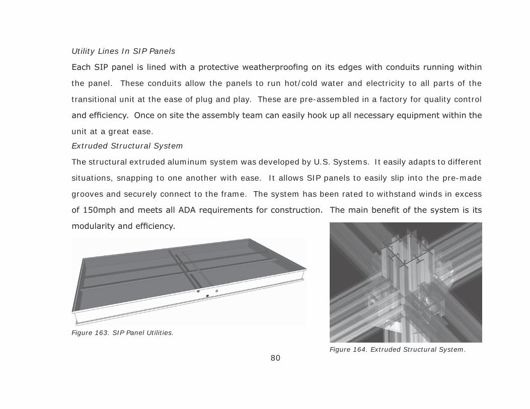
Utility Lines In SIP Panels
Each SIP panel is lined with a protective weatherproofing on its edges with conduits running within
the panel. These conduits allow the panels to run hot/cold water and electricity to all parts of the
transitional unit at the ease of plug and play. These are pre-assembled in a factory for quality control
and efficiency. Once on site the assembly team can easily hook up all necessary equipment within the
unit at a great ease.
80
Extruded Structural System
The structural extruded aluminum system was developed by U.S. Systems. It easily adapts to different
situations, snapping to one another with ease. It allows SIP panels to easily slip into the pre-made
grooves and securely connect to the frame. The system has been rated to withstand winds in excess
of 150mph and meets all ADA requirements for construction. The main benefit of the system is its
modularity and efficiency.
Figure 163. SIP Panel Utilities.
Figure 164. Extruded Structural System.

81
CONSTRUCTION ASSEMBLY OF UNIT
This time line further breaks down and details the time period when the Transitional Housing Unit is
in use. One time line is for a temporary unit and the other is for a permanent unit. After each time
line is a diagram of the steps that are detailed in the time line.
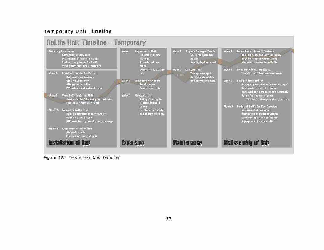
82
Figure 165. Temporary Unit Timeline.
Temporary Unit Timeline

Figure 166. Temporary Unit Digram.
83

Figure 167. Permanent Unit Timeline.
84
Permanent Unit Timeline

Figure 168. Permanent Unit Digram.
85

Final Designs
86
Temporary Unit
The design of the Temporary Unit is a compilation of the
initial design and secondary designs. After the sectional
and material studies the design evolved into a cohesive
unit that represents all the design principles laid out early
in the process. The roof line angles towards the south in
order to capture the most sun for the photovoltaic cells on
the top. The plan shows the layout of the interior spaces
with finishes that would be found in a typical unit. There
is a visual connection across the unit that connects all the
spaces around the living space.
Figure 169. Temporary Unit Render.
Figure 170. Temporary Unit Plan.
Figure 171. Temporary Unit Section.

87
Figure 172. Temporary Unit Model.
Figure 173. Temporary Unit Model. Figure 174. Temporary Unit Model.

88
Permanent Unit
The permanent unit follows the outlines of the original
foundation and expands to reach its edges. Close study
of the previous home took place prior to the initial design
since this unit will remain permanent. After a year at the
early stage the unit begins to add additional floors and
wall to expand the rooms. Originally the idea was to add
individual walls and coverings but after further investigation
it was found to be easier to add entire rooms or spaces to
the central space. That way the exterior envelope remains
enclosed. After all the spaces have been added the entire
unit is re-assessed for sealed joints around fenestrations.
Figure 175. Permanent Unit Render.
Figure 176. Permanent Unit Plan.
Figure 177. Permanent Unit Section.

89
Figure 178. Permanent Unit Model.
Figure 180. Permanent Unit Model.Figure 179. Permanent Unit Model.

90
PRODUCT MEDIA
One of the key points of this research is to provide a solution to solve the current problems. For this
plan to be truly ready for implementation it must have the documents prepared for it to be used.
One of these such documents is a Product Guide that will guide the victim through the process of
selecting a size, type, configuration, and all the components of the transitional housing unit. The
following pages form the Product Guide for the ReLIFE Transitional Housing Unit. This product guide
develops this design from a fictional idea into a reality that is ready to be tested with the public.

90
Figure 181. Product Guide P1,P8. Figure 182. Product Guide P2,P3.

90
Figure 183. Product Guide P4,P5. Figure 184. Product Guide P6,P7.

91
BIBLIOGRAPHY
Design Like You Give a Damn. (2006). New York: Metropolis Books.
FEMA: The Disaster Process and Disaster Aid Programs. (2006, September 13). Retrieved April 2009,
from FEMA: http://www.fema.gov/hazard/dproc.shtm
FEMA-Provided Travel Trailer Study. (2008, November 13). Retrieved April 2009, from Center for
Disease Control and Prevention: http://www.cdc.gov/nceh/ehhe/trailerstudy/formaldehyde.htm
Hartman, C., & Squires, G. D. (2006). There is No Such Thing as a Natural Disaster: Race, Class,
and Hurrican Katrina. New York: Taylor and Francis Group, LLC.
Henneberger, J. (2008, December 15). Put an end to FEMA trailers by moving people quickly into
permanent housing. Retrieved April 2009, from Texas Housers: http://texashousers.net/2008/12/15/
put-an-end-to-the-fema-trailer-by-moving-directly-to-permanent-housing/

92
Hurricane Charley. (2009, July 20). Retrieved July 26, 2009, from Wikipedia: http://en.wikipedia.
org/wiki/Hurricane_Charley
IKEA Concept. (2009, March 11). Retrieved March 11, 2009, from IKEA: http://www.ikea.com/ms/
en_US/about_ikea_new/about/index.html
Institue, S., & Institute, S. (2007). Design for the Other 90%. New York: Cooper-Hewitt National
Design Museum.
Kerensky, B. (2008, July 11). TOP STORY: Toxic trailers from FEMA still source of debate and
concern . Retrieved April 2009, from Oh My Gov: http://ohmygov.com/blogs/general_news/
archive/2008/07/11/toxic-trailers-from-fema-still-source-of-debate-and-concern.aspx
Kronenburg, R. (2008). Portable Architecture: Design and Technology. Boston: Architectural Press.
Kronenburg, R. (2003). Transportable Environments 2. New York: Spon Press.
Myers, L., & Gardella, R. (2007, November 15). $229,000 FEMA Trailers. Retrieved April 2009, from
MSNBC: http://www.msnbc.msn.com/id/21824609

93
Natsios, A. S. (1997). U.S. Foreign Policy and the Four Horsemen of the Apocalypse: Humanitarian
relief in complex emergencies. Connecticut: Praeger Publishers.
Press, A. (2009, January 17). USA Today. Bush administration finishes disaster housing plan .
Schittich, C. (2003). In Detail: solar architecture. Switzerland: Publishers for Architecture.
Siegal, J. (2008). More Mobile: Portable Architecture for Today. New York: Princeton Architectural
Press.
Stang, A., & Hawthorne, C. (2005). The Green House: new directions in sustainable architecture.
New York: Princeton Architectural Press.
Stone, J. (2009, April 9). USA Today. More communication, education needed in hurricanes .
Topham, S. (2004). Move House. Munich: Prestel.