Safety relief valve manufacturers, Pressure relief valve manufacturers
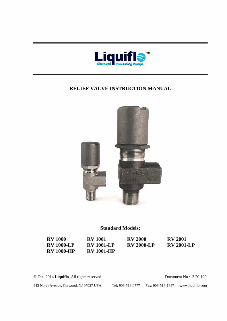
RELIEF VALVE INSTRUCTION MANUAL
Standard Models: RV 1000 RV 1001 RV 2000 RV 2001 RV 1000-LP RV 1001-LP RV 2000-LP RV 2001-LP RV 1000-HP RV 1001-HP
© Oct. 2014 Liquiflo, All rights reserved Document No.: 3.20.100 443 North Avenue, Garwood, NJ 07027 USA Tel: 908-518-0777 Fax: 908-518-1847 www.liquiflo.com
TM
LIQUIFLO Relief Valve Instruction Manual
2
Relief Valve Instructions: (Refer to diagram on page 3.) Your new Liquiflo Relief Valve is maintenance free. The only adjustment on the valve is the resetting of the relieving point. This is done by loosening the lock nut (2) and rotating the large cap (1). (Turn cap COUNTERCLOCKWISE for lower relief setting; turn CLOCKWISE for higher relief setting.) A general guideline for pressure setting is 10-15 PSI above the system operating pressure. The relief valve should be installed as close to the pump as possible and without any valves or accessories between the relief valve and the pump.
If, for any reason, the valve must be disassembled, this can easily be done by loosening the lock nut (2) and unscrewing the adjusting cap (1). Remove the safety pin (7) and pull out the internal spring cap (8). This exposes the spring (4) and valve pin (5) assembly.
For reassembly, simply reverse the above action. (Push in the internal spring cap with spring and valve pin, replace the safety pin, etc.)
CAUTION: ALWAYS MAKE SURE THERE IS NO PRESSURE IN THE SYSTEM BEFORE DISASSEMBLING THE VALVE. IT IS BEST TO REMOVE THE VALVE FROM THE SYSTEM. Always flush the system before disassembling to eliminate the chance of getting harmful materials on the skin or in the eyes.
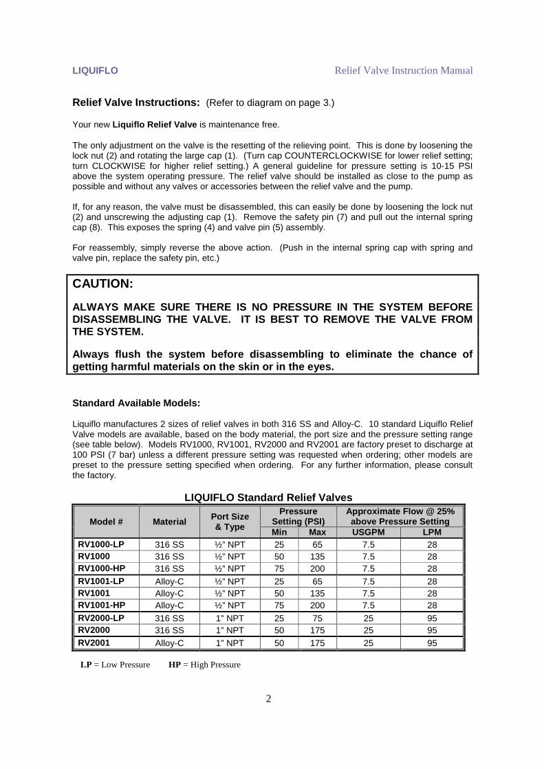
Standard Available Models: Liquiflo manufactures 2 sizes of relief valves in both 316 SS and Alloy-C. 10 standard Liquiflo Relief Valve models are available, based on the body material, the port size and the pressure setting range (see table below). Models RV1000, RV1001, RV2000 and RV2001 are factory preset to discharge at 100 PSI (7 bar) unless a different pressure setting was requested when ordering; other models are preset to the pressure setting specified when ordering. For any further information, please consult the factory.
LIQUIFLO Standard Relief Valves
Model # Material Port Size & Type
Pressure Setting (PSI)
Approximate Flow @ 25% above Pressure Setting
Min Max USGPM LPM RV1000-LP 316 SS ½” NPT 25 65 7.5 28 RV1000 316 SS ½” NPT 50 135 7.5 28 RV1000-HP 316 SS ½” NPT 75 200 7.5 28 RV1001-LP Alloy-C ½” NPT 25 65 7.5 28 RV1001 Alloy-C ½” NPT 50 135 7.5 28 RV1001-HP Alloy-C ½” NPT 75 200 7.5 28 RV2000-LP 316 SS 1” NPT 25 75 25 95 RV2000 316 SS 1” NPT 50 175 25 95 RV2001 Alloy-C 1” NPT 50 175 25 95
LP = Low Pressure HP = High Pressure
LIQUIFLO Relief Valve Instruction Manual
3
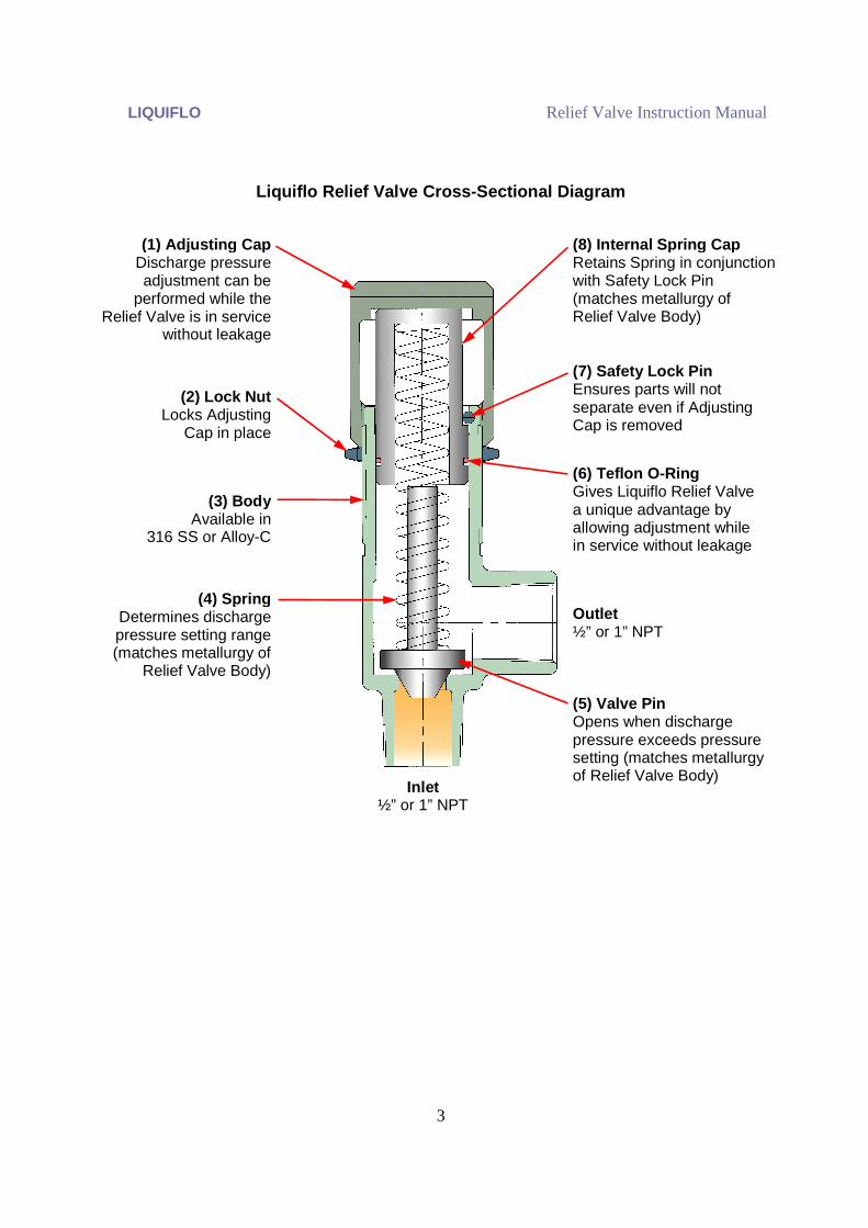
Outlet ½” or 1” NPT
(6) Teflon O-Ring Gives Liquiflo Relief Valve a unique advantage by allowing adjustment while in service without leakage
(3) Body Available in
316 SS or Alloy-C
(4) Spring Determines discharge pressure setting range (matches metallurgy of
Relief Valve Body)
(8) Internal Spring Cap Retains Spring in conjunction with Safety Lock Pin (matches metallurgy of Relief Valve Body)
(7) Safety Lock Pin Ensures parts will not separate even if Adjusting Cap is removed
(2) Lock Nut Locks Adjusting
Cap in place
Inlet ½” or 1” NPT
(5) Valve Pin Opens when discharge pressure exceeds pressure setting (matches metallurgy of Relief Valve Body)
(1) Adjusting Cap Discharge pressure adjustment can be
performed while the Relief Valve is in service
without leakage
Liquiflo Relief Valve Cross-Sectional Diagram