Reliance: Herreshoff Marine Museum - DOCS@RWU
72
Roger Williams University DOCS@RWU Engineering and Construction Management Community Partnerships Center 2013 Reliance: Herreshoff Marine Museum Arnold Robinson Community Partnerships Center, [email protected] George Dalton Sean Damico Eric Doremus Brian Fortier See next page for additional authors Follow this and additional works at: hp://docs.rwu.edu/cpc_ecm Part of the Engineering Commons , and the History Commons is Document is brought to you for free and open access by the Community Partnerships Center at DOCS@RWU. It has been accepted for inclusion in Engineering and Construction Management by an authorized administrator of DOCS@RWU. For more information, please contact [email protected]. Recommended Citation Robinson, Arnold; Dalton, George; Damico, Sean; Doremus, Eric; Fortier, Brian; Goncalo, Jeffrey; and Lee, Arthur, "Reliance: Herreshoff Marine Museum" (2013). Engineering and Construction Management. Paper 1. hp://docs.rwu.edu/cpc_ecm/1
Transcript of Reliance: Herreshoff Marine Museum - DOCS@RWU

Roger Williams UniversityDOCS@RWU
Engineering and Construction Management Community Partnerships Center
2013
Reliance: Herreshoff Marine MuseumArnold RobinsonCommunity Partnerships Center, [email protected]
George Dalton
Sean Damico
Eric Doremus
Brian Fortier
See next page for additional authors
Follow this and additional works at: http://docs.rwu.edu/cpc_ecm
Part of the Engineering Commons, and the History Commons
This Document is brought to you for free and open access by the Community Partnerships Center at DOCS@RWU. It has been accepted for inclusionin Engineering and Construction Management by an authorized administrator of DOCS@RWU. For more information, please contact [email protected].
Recommended CitationRobinson, Arnold; Dalton, George; Damico, Sean; Doremus, Eric; Fortier, Brian; Goncalo, Jeffrey; and Lee, Arthur, "Reliance:Herreshoff Marine Museum" (2013). Engineering and Construction Management. Paper 1.http://docs.rwu.edu/cpc_ecm/1

AuthorsArnold Robinson, George Dalton, Sean Damico, Eric Doremus, Brian Fortier, Jeffrey Goncalo, and Arthur Lee
This document is available at DOCS@RWU: http://docs.rwu.edu/cpc_ecm/1


The Roger Williams University Community Partnerships Center The Roger Williams University (RWU) Community Partnerships Center (CPC) provides project-based assistance to non-profit organizations, government agencies and low- and moderate-income communities in Rhode Island and southeastern Massachusetts. Our mission is to undertake and complete projects that will benefit the local community while providing RWU students with experience in real-world projects that deepen their academic experiences.
CPC projects draw upon the skills and experience of students and faculty from RWU programs in areas such as: • ArchitectureandUrbanDesign • HistoricPreservation • Law • JusticeStudies • Business • Education • EngineeringandConstructionManagement • EnvironmentalScienceandSustainability • CommunityDevelopment • VisualArtsandDigitalMedia • MarketingandCommunications • GraphicDesign • PoliticalScience • Psychology • History • AmericanStudies • Finance • PublicAdministration • PublicRelations • WritingStudies • SustainableStudies
Community partnerships broaden and deepen the academic experiences of RWU students by allowing them to work on real-world projects, through curriculum-based and service-learning opportunities collaborating with non-profit and community leaders as they seek to achieve their missions. The services provided by the CPC would normally not be available to these organizations due to their cost and/or diverse needs.
i
CPCProjectDisclaimer:Thereadershallunderstandthefollowinginregardstothisprojectreport: 1. The Project is being undertaken in the public interest; 2. The deliverables generated hereunder are intended to provide conceptual information only to assist design and planning and such are not intended, nor should they be used, for construction or other project implementation. Furthermore,professionaland/orotherservicesmaybeneededtoultimatelyimplementthedesiredgoalsofthepublic in ownership of the project served. 3. The parties understand, agree and acknowledge that the deliverables being provided hereunder are being performed by students who are not licensed and/or otherwise certified as professionals. Neither RWU nor the CPC makes any warranties or guarantees expressed or implied, regarding the deliverables provided pursuant to thisAgreementandthequalitythereof,andSponsorshouldnotrelyontheassistanceasconstitutingprofessionaladvice. RWU, the CPC, the faculty mentor, and the students involved are not covered by professional liability insurance. 4. Neither RWU, the CPC, the faculty mentor, nor the students involved assume responsibility or liability for thedeliverablesprovidedhereunderorforanysubsequentusebysponsororotherpartyandSponsoragreestoindemnifyandholdharmlessRWU,theCenter,theFacultyMentor,andtheCenter’sstudentagainstanyandallclaimsarisingoutofSponsor’sutilization,sale,ortransferofdeliverablesprovidedunderthisAgreement.
Community Partnerships Center Roger Williams University OneOldFerryRoad Bristol,RI02809 [email protected] http://cpc.rwu.edu
ii

Te
ENGR 490 Fall 2012
Building a Museum Quality, 1/6th Scale Replica of the 1903 Americas Cup Defender,
Submitted: 12/14/2012Lead Engineers: George Dalton | Sean Damico | Eric Doremus | Brian Fortier | Jeffrey GoncaloClient: Arthur Lee | Herreshoff Marine MuseumFaculty Supervisor: Dr. William Palm
chnical Mentor: Dr. Gilbert BrunnhoefferIn Partnership With: Herreshoff Marine Museum, Bristol RI
iii
TheRogerWilliamsUniversityRelianceteamisworkingincooperationwiththeHerreshoffMarineMuseuminBris-tol,RItocreatea1/6thscalemodelofthe1901AmericasCupdefender,theReliance.Theprojectcanbebrokenupintotwosub-projects.Thefirst,todesignamuseum-qualitycradletoholdthe24ftfullyriggedmodelata15Oangle.The second sub-project is to perform full strength/structural analysis of all the critical components on the model to ensure that their strength is great enough to withstand the applied forces. This second sub-project is going to be the focusofthespring2013semesterwhiletheFall2012semesterfocusedonthecradledesign.
Afterdeterminingourfinalcradledesign,structuralanalysisvalidatedtheuseoftwosquarechannel4”x4”x0.5”steelcolumnsforthe‘legs’ofthecradle,while3/8”boltssecuredC3x3.5A36steeloutriggerbeamstothecenterbeamconstructedofAmericanStandardS3x5.7A36steel.
Abstract
iv
Table of Contents
v

vi

List of Figures
vii
List of Tables
viii
List of Acronyms
Ourclientandprojectmanager,SandyLeefromtheHerreshoffMarineMuseum(HMM),proposedadesignprojecttothestudentsoftheEngineeringDesigncourseatRogerWilliamsUniversitytoassisttheHMMinthebuildingofa1/6thscalereplicaofthe1901AmericasCupDefender,theReliance. This project includes structural analysis of the criticalcomponentsonthemodel,aswellasdesignandanalysisofacradlethatwillholdthemodelata150angle.TheoriginalRelianceyachtmeasured205ftfromthetipofthebowsprittotheendoftheboomand220ftfromthebottom of the keel to the tip of the topmast. Our 1/6th scale replica will measure roughly 33ft from tip to tip and 37ftfromkeeltotipoftopmast.Thisscaledmodelwillbefullyriggedwithsailsandalltheriggingcomponentswillbe produced using similar materials to those that were used on the original yacht.
Lookingdeeperintothedesigningofacradleandstructuralanalysisofcriticalcomponents,foreaseofconstruction,theHMMwouldalsolikeexpertiseonstructuraladhesivesthatmaybeusedonthemodelandcradledesigns.Ourgoalistodevelopthecradledesigninsuchamannerthatitmeetsallrequirementsoftheclientincludingbutnotlimited to portability, display angle, and above all safety. Afterreviewingwhatneededtobedonetocompletethedesignproject,ourteambrokedowntheworkforthe2012falland2013springsemester.Itwasdeterminedthatthemostpracticalapproachwouldbetofinalizeacradledesignby the end of the fall semester and perform all structural analysis on the model during the spring semester.
Introduction
1
AtthebeginningofourfallsemestertheHMMandMr.Leeseemedtohaveaveryclearvisionofwhattheywantedforthecradledesign.AfterextensivecommunicationbetweenthegroupandMr.Lee,wefoundourlistofcustomerneedsgrowingwitheachmeeting.ThroughourmeetingswithMr.Leeweformedalistofcradledesignconstraintsand assumptions, as shown below, to guide our team in the formulating of our designs.
1.CradleDesignConstraints a. Needs to be portable b.15degreetilt c.Structurallysound d.Aestheticallypleasing e.Lowcost f.Lessobtrusiveisbetter 2.Assumptions a. Model will never be placed in the water or sailed b. Model will never be displayed without the cradle c. Model will be indoors at all times
Oneofthekeyobjectivesofourprojectwastohavedisplaysofthehull,deckandsparsintimeforthisyear’sJuly4thactivitiesthatwilltakeplaceinBristol.
To ensure our team is staying on task we have adopted the following mission statement:“The2012-2013HerreshoffMarineMuseumSeniorDesignprojectencompassesnumeroustaskstoassisttheHer-reshoffteaminthestructuraldesignandanalysisofa1/6thscalemodeloftheReliancewithsafetyandqualityatthehighestpriority.”
Throughout the year we plan to look back on our mission statement to ensure we have not lost sight of our goals and ensureweareworkingtosatisfyingtheneedsofourclient,theHerreshoffMarineMuseum.Wearehappytoprovideaid to a local non-profit organization to establish a partnership between Roger Williams University and the local com-munity to hope to build on this relationship in the years to come.
2

TheRWURelianceteamiscomposedof5seniorcivilengineeringstudentsaswellastwofacultymentorsandsuper-visors.GeorgeDalton,SeanDamico,EricDoremus,BrianFortier,andJeffreyGoncalomakeupthestudentportionofthegroup.Theteam’stechnicalmentorisDr.GilbertBrunnhoefferwhileDr.WilliamPalmactsastheteam’ssupervisor.
GeorgeDaltonhasengagedaleadroleincreatingSolidWorksmodelsofvariouspartsofthemodel,suchastheboom,gaff,andspars,aswellasderivingaprocesstocalculatethecenterofgravityofthehull.HeworkedwithEricDore-mustopresentatthe2012RI-ASCESpaindinnerinNarragansett,RIandhasmadeamajorcontributiontowardsthe final cradle design specifications.
SeanDamicohastakentheroleasthestudentprojectmanager.HisexpertiseinSolidWorkshasbeenputtousetocreateseveraldraftsofthemanycradledesignsthatdevelopedduringthecourseofthisproject.Hehasorganizedthe team, using resources such as Microsoft Project to keep the team on track and on schedule. In addition to this, Mr.Damicohasputforthamajoreffortinmilestonereportsaswellasanalysisanddesignofthefinalcradledesign.
EricDoremushasassumedtheresponsibilityofdraftinga3DmodelofthehullinSolidWorksanddraftingtheinitialteamPowerPointpresentations.Hehasalsobeenputinchargeoftheteam’sbinderaswellasputtingtogetherthefinalreport,makingsurethatallimportantdocuments,emails,andmeetingsareaccountedfor.Hisknowledgeandexperienceof3DprintingtechnologyaswellasSolidWorksexperiencehasbeenputtouseduringthecourseofthisproject.
BrianFortiercreatedhisownuniquecradledesignaswellasworkedhandinhandwithMr.Daltontocalculatethecenterofgravityofthemodelhull.HehasplayedamajorroleinthecompletionofthevariousMilestoneReportsand has made many contributions towards finalizing the member sizing in our final cradle design.
JeffreyGoncaloputforthamajorefforttocalculatethecenterofgravityoftheupperriggingofthemodel.HehasputforthamajorefforttowardsthecreationofPowerPoint’s,milestonereports,aswellasrevisionstofinalizethecradle design.
Project Planning
3

UponreceivingourinitialprojectstatementonSeptember17th,aninterviewwithMr.Lee,theHMMRelianceProj-ectManager,wasimmediatelyestablishedforSeptember20th.InpreparationforthemeetingourgroupcomposedseveralquestionsthatwereemailedtoMr.Leeforourmeeting.Duringourmeeting,Mr.Leerelayedhisanswersingreatdetailincludingwhathewouldliketoseeasthefinaloutcomeofouryear-longproject.Atthemeetingweobserved the layout of the museum, the proposed location of the display, and the actual hull of the Reliance model. Mr.LeealsopresentedcopiesoftheoriginalRelianceplansforconstruction.Afterdeterminingtheteam’sobjectives,itwasrecognizedthattheprojectwasgoingtorequireagreatdealofinformationregardingthespecificationsofthemodel.ItwascommunicatedtoMr.Leethatitwouldbenecessaryfortheteamtoacquireextensiveplansinordertosuccessfullyanalyzethemodelandcreateaneffectivecradledesign.Mr.Leewasabletoscanwhatplanshehadontoadiskaswellasdrawseveralviewsofthemodelindetail.ThedisksanddrawingsweretransferredtoMr.DamicoonSaturday,September29th.TheteamcontinuedtostayincontactwithMr.Leeforfuturerequireddataincluding,but not limited to, the weight of the model, center of gravity, weight of mast, material of mast, hull cross sections, and the thickness of the hull.
Customer Needs AnalysisData Collection Approach
4

Summary of Raw Data
5

Hierarchical List of Primary and Secondary Needs
Importance ratings for the secondary needs are indicated by the number of *’s, with *** denoting critically important needs.
6

Reflections on Results and Process
We have interacted with the client a great deal since the beginning of the project. Through these exchanges, we have discovered numerous design objectives the client would like us to achieve. The needs of our customer were prioritized bywhatMr.Leediscussedwhenaskedwhathewantedustoaccomplish.Sinceourcradledesignwillbeseenbythegeneralpublic,safetyisoftheutmostimportance.Allofthestructuralneedswerebasedoffoftheideaofmakingitsafe,whereasallofourotherneedsdealtwiththestructure’saestheticappeal.Someaspectsofthestructure’saestheticsweredeterminedmoreimportantthanothersbasedonwhatMr.Leestressedmultipletimes.Furthermore,wereal-ized that these objectives will be hard to achieve if we are not given numerous specifications relating to the model. We willbeworkingwithMr.Leeperiodicallytoensurealldesiredmodelinformationisacquired.
Togainanevengreaterunderstandingofthecustomers’needs,wecouldinteractwithpeopleotherthanourprojectmanager,Mr.Lee.TheReliance model is being built for museum visitors, so their input is also very important. We could interview these museum visitors or have them fill out a survey to get an understanding of what they would like to see. In order to get possible overlooked information on the Reliance,wecouldtalktotheHerreshoffMuseumstaff,volunteers, or the RelianceenthusiaststhatMr.Leehasmentionedtous.Whilewefeelwehaveagreatunderstand-ingofwhatourcustomers’needsare,ourteamneedstomakesureeveryoneaffectedbythisproject’svoiceisheard.
7

Target SpecificationsExecutive SummaryThe target specifications were concluded by analyzing customer needs, constraints, and various similar designs on the markettoday.Althoughnumerousmetricsalreadyexistwithinourprojectduetothelackofalterationstothemodel,we comprised a list based on the needs and design goals given to us by our client. The metrics are compared to those insimilarprojectsinthemaritimeandmarinemodelingfield.However,duetothenatureofthisprojectbeingacustom build many typical applications do not closely coincide with those found in this project. Ultimately from our analysis we were able to determine the key metrics that will prove to define the success of our work as it relates to meetingandorexceedingourclient’sneeds.
IntroductionThefollowinganalysisisbasedupontheneedspresentedtousbyourclientMr.LeefromtheHerreshoffMarineMuseum. Most needs were generated from specific lines of work necessary to the success of the overall project. Oth-ershavestemmedfromthesetocoverallnecessaryworktobecompleted.Fromtheseneedsasystemofmetricsweredeveloped to account for necessary standards and means by which our design and analysis must adhere to for overall successofthedesiredrequirements.InTable4acomparisonofeachmetricismadetotheirdesignatedneed.
InthesubsequentTablesthecostumersneedsandtheirrespectivemetricshavebeenbenchmarkedtothoseofsimilarprojects and or practices currently found in the field today. The RelianceprojecthasbeencomparedtotheAmericasCupExhibitattheMFAinBoston,TheDefiant,currentlyonexhibitoutsidetheHMM,andstandardizedboatsup-portsfoundattheNewportBoatYard.Fromthesethreeoutsidesourcesweareabletogainagreaterunderstandingof both the importance of each need as it pertains to similar projects and how well each source correlates by means of metrics.
8

Benchmark ComparisonsTheAmericasCupexhibitattheMFAin2005showedtwofullsizeAmericasCupsailboatstiltedataslightangletoreplicatethelooksasiftheywereundersail.Althoughtheseboatswereplacedoutsideandwerenotriggedwithanysails,wewereinspiredbythefactthattheywereonlysupportedbycables.The1992AmericasCupcontender,theDefiantiscurrentlyplacedoutsideonapermanent,uprightstructureinfrontofHMM.ThisInternationalAmeri-casCupClassboatis75ftlonganddoesnothaveanysailsriggedatthetime.Althoughthisboatisnotplacedatanangle,itgaveusagoodideaonhowwecouldpossiblysupportthemodel.Standardboatsupports,whichcanbeseen at any boat yard, are typically used for short term storage. We have ruled these out of our possible cradle design becauseoftheirbulkinessandlimitedabilitytoplacetheboatatanangle.Sinceourdesignissounique,itishardtocompareitwiththebenchmarkslistedabove.OurprojectstandsoutonitsownbecauseofthefactthatHMMistryingtoreplicateaboatfrom1903,usingthesameorsimilarmaterialsthatwouldhavebeenfoundontheboat.Thehulldoesnotholdthenormalstructuralintegritythattheactualboatwouldhave,soauniquecradledesignwithan internal support is necessary to provide structure to the model.
9

Methods and Results
Specificationswereestablishedthroughamulti-stepprocesswhichtranslatedcustomerneedintodesignspecifica-tions.First,acustomerneedstablewascreatedandtheimportanceofeachneedwasrankedonascaleofonetofiveas displayed in Table 2. The customer needs were established through client meetings in which our group was briefed on their overall vision of the project. The importance rating assigned to each need was determined by considering the clients stress on the individual need as well as its importance to the overall outcome of the project.
Table 2: Project Metrics based upon customer needs as listed in Table 1. Each metric is related to specific needs and ranked by importance. Units have been provided for each metric in the quantity in which they
are evaluated.
10

Next, a list of metrics surrounding the project was generated from the customer needs. The list consists of general specifications that will be needed to successfully complete the project since the Reliance consists of several hundred minor specifications that branch from those listed. The metrics were then linked to their correspondent customer needs in a needs-metrics matrix displayed in Table 3.
Table 3: Metrics Benchmarking. All metrics found in Table 2 are com-pared to three outside sources. As seen above many of the metrics do
not correlate from the Reliance project to other models and or stan-dards found in the field today.
11

In order to compare the specifications of the Reliance Project with similar projects a metrics competitive benchmark-ing chart was created as shown in Table 4. Metrics of the comparative projects were determined through research of theprojects.Afterestablishingmetricsofsimilarprojects,thecustomerneedsofourprojectwererelatedtothecom-parative projects and ranked by importance. The customer needs importance of the related projects was determined through analysis of assumed goals of the respective designs.
Table 4: Needs Benchmarking. Each need as seen in Table 1 above has been compared to those in the three outside sources as seen in the last three columns. From this table we are able to see how the needs of our project correlate to those in other previously com-
pleted projects. This will allow us to easily find resources for problems that may develop among our specified needs and look into different means by which they were overcome.
12

Concept GenerationExecutive SummaryStemmingfromourclient’sneedsandexternalvisits,conceptdesignswereconstructedandcompared.Theclientneeds were then used to establish selection criteria and the concept designs were compared to determine how well they metthecriteria.Eachdesignwasthengivenaratingforhowwellitmeteachselectioncriteriaandaweightedratingsystem was constructed based on the importance of the criteria. The data concluded the hybrid designs met the most client needs and therefore should be examined further.
13

Introduction
ConceptDesignshavebeenformedbyanalyzingvariouscriteriaincludedinthecustomerneedsandconstraints.Theconceptswerealldesignedwiththeclient’sdesiresinmind,buttakedifferentapproachesindoingso.
FromourinitialmeetingwithMr.LeeonSeptember20th2012,untilourgroupmeetingonOctober18th,2012,everymemberofourgroupbrainstormeddesignideasindividually.Everyonewasresponsiblefordraftingadesignfor the cradle that would hold up the model. Throughout the process of identifying customer needs and developing targetspecifications,thegrouptookuniquemeasuresofgettinginspirationtocomeupwithacreativesolutiontoour design problem.
AfterourinitialmeetingonSeptember20th,Mr.LeewaskindenoughtotakethegrouponatouroftheHerreshoffMarineMuseumandtheworkshopsonthemuseum’sgrounds.Wewereabletoseeotherlargemodelsofboatsandhowtheywereputondisplay.AlthoughthedisplayfortheReliancemodelwillbeuniquetotheothermodelscur-rently at museum, we were able to see how a cradle enhances the viewing of the model. On the tour we were also able to see the hull of the Reliance model for the first time. Once seeing it in person, we were able to understand the grandeur this model will project once it is completed.
InfrontoftheHerreshoffMarineMuseum,istheInternationalAmerica’sCupClassboat,theDefiant.Theboatis75feet long and is held upright. It is visible from Route 114, which the Reliance model will be too, once it is completed. The boat gave us on idea of how massive the rigging will be on our model in comparison to the hull.
OnSaturday,September22nd,thegrouptookatriptoNewport,RhodeIsland,tovisittheNewportShipyard.Thereweremanydifferentshapes,sizes,andtypesofshipsthatwereinthewaterandhelduprightonland.Whilemostoftheshipswerehelduprightbythestandardsteelblocksthatareheldplacedaroundthehull,somerequiredextrasupport to keep it up straight. One of the ships in particular, used a very thick rope tied from the top of the topmast to a large concrete block on the ground. This inspired the idea of cable stabilizers that appeared in a few of the early concept designs.
OnOctober18th,allmembersofthegroupcametogetherintheShawmutConstructionRoominRogerWilliams’Engineeringbuildingwithourdesignconcepts.Wedrewallofourdesignsonagiantwhiteboardandwentthroughtheideabehindeachdesign.Wediscussedwhatwelikedabouteachdesignandwhatwethoughtwasn’tpragmatic.Asagroup,wevotedonthreedesignstomoveforwardwithandpresenttoourprojectmanager,Mr.Lee.
14

Concept DesignsCantilever CradleConceptDesign#1allowsforthemodeltobefullysupportedwithminimalobstructiontothehullfromthefrontalviewasshownbelowinFigure1.
Figure 1: Cantilever Cradle front viewer’s perspective
In this design the active rigging components tie directly into the internal structure and the hull itself is supported along the outside edge of the deck. This will ensure that there are no forces that will jeopardize the integrity of the fiberglass and that the mast and rest of the rigging components rely purely on the structural integrity of the internal structure,displayedbelowinFigure2.
Figure 2: Cantilever Cradle internal structure and frame.
15

Lookingintotheinternalstructureitselfweseethatthemastissupportedbyasteelframe.Thedesignofsailboatsmakes it so that at the mast connection point there are only direct compressive forces and the active stays are pure tensileforces.Becauseofthis,themastsupportframewillbeactingagainstthecompressiveforceexertedandthestayswill be attached to the outer edge of the frame to take all of the tensile forces exerted. Ultimately by this concept we arecompletelyremovingthefiberglasshullfromthemodel’sstructuralintegrityandthecradleitselfcoulddisplaythemast and the rest of the rigging without the hull in place.
To counteract the moment created by the cantilever design the rear of the upright structure will be bolted to the groundorinthecasethisisunobtainable,weightwillbeaddedtotherearofthebaseplate.Asfortheportabilityofthe cradle the internal structure can be detached from the base and uprights by means of pins. This will allow for the two members to become completely separate from one another to enable ease of transportation and a smaller profile foraccessintotheTFGreenairportandotherbuildingsinwhichitmayendupbeforeitsfinalhomeatHMM.
Free FloatingOursecondconceptdesignisbasedoffapreviousdisplayofAmerica’sCupboatsattheBostonMuseumofFineArtsbyRogerMartinDesign.Thisdesignissupportedbyasinglesteelcolumnplacednearthecenterofmassandcon-nectedtoaballandsocketjoint,asshowninFigure3.
Figure 3: Free Floating viewer’s perspective
16

Fourstabilizingcables,twoatthebowandtwoatthesternwillbetiedintoacentercolumnI-beam,whichrunsthelengthofthehull.AsupportcableconnectedtoawallorsurfacerunningparalleltotheI-beamwillactasadditionalsupportforthestructure,asshowninFigure4.
Figure 4: Free Floating internal structure
TheinternalstructurewillconsistofasteelI-Beamextendingthelengthofthehull,equippedwith5C-channelsand1I-Beamatthemastlocation.Thesebeamswillactassupportforthehullhavingthedeckrestontherubberpaddingat the ends of the beams as well as support for the main riggings which will be tied into the C-channel to take the load offthehull.ThemastistobesupportedbyasteelmastsleevehavingasteelplateboltedintotheI-Beamandbracedtogiveextrasupport.ThecentercolumnwillbeboltedintothebottomoftheI-Beamandalsobracedtogiveextrasupport. The structure will then be placed in a ball and socket joint, which is mounted by a concrete footing, allowing the boat to rotate and adjust the angle if necessary. The purpose of this design is to give the model an aesthetically appealinglookbyappearingtobefreefloatingandsupportedbyacosteffectiveminimalstructure.
17

Natural Surroundings
ForConceptDesign3wetookadifferentapproachbyincorporatingtheboat’snaturalsurroundingsintothecradle.TheReliancewillbeheldata10°angletoportraytheboatcuttingthroughtheoceanwhileundersailasshowninFigure5andFigure6
Figure 5: Natural Surroundings front viewer’s perspective
Figure 6: Natural Surroundings back viewer’s perspective
18
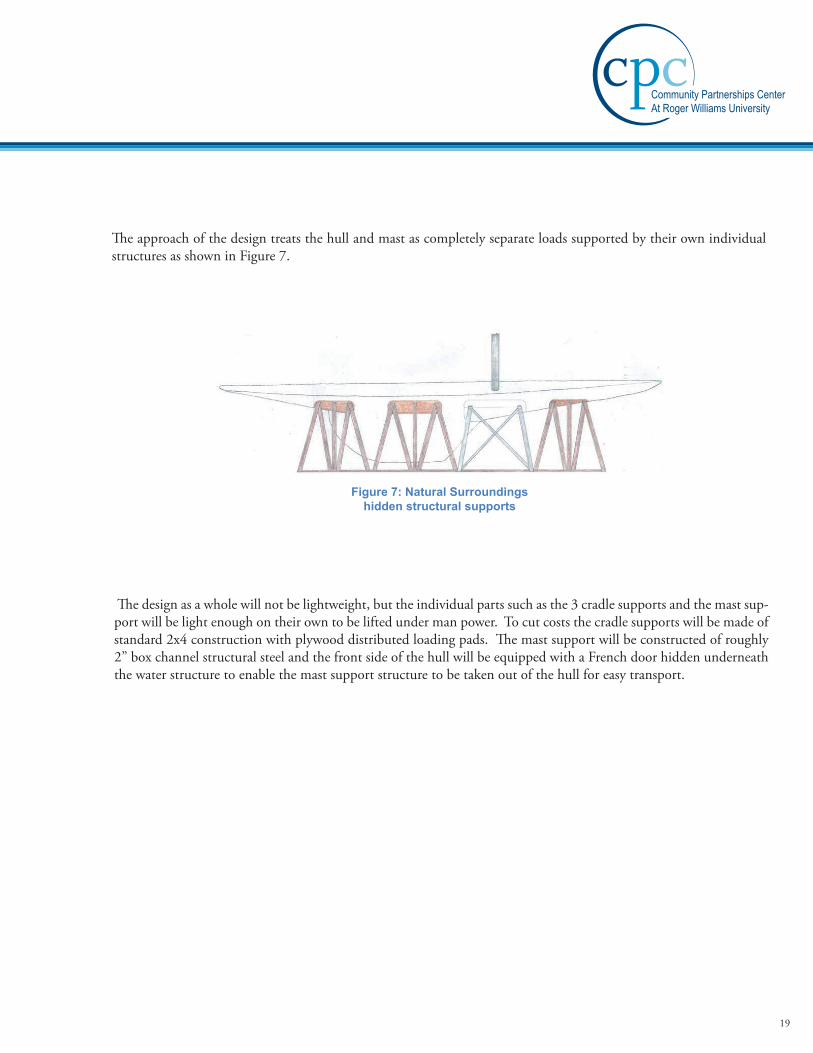
The approach of the design treats the hull and mast as completely separate loads supported by their own individual structuresasshowninFigure7.
Figure 7: Natural Surroundings hidden structural supports
The design as a whole will not be lightweight, but the individual parts such as the 3 cradle supports and the mast sup-port will be light enough on their own to be lifted under man power. To cut costs the cradle supports will be made of standard 2x4 construction with plywood distributed loading pads. The mast support will be constructed of roughly 2”boxchannelstructuralsteelandthefrontsideofthehullwillbeequippedwithaFrenchdoorhiddenunderneaththe water structure to enable the mast support structure to be taken out of the hull for easy transport.
19
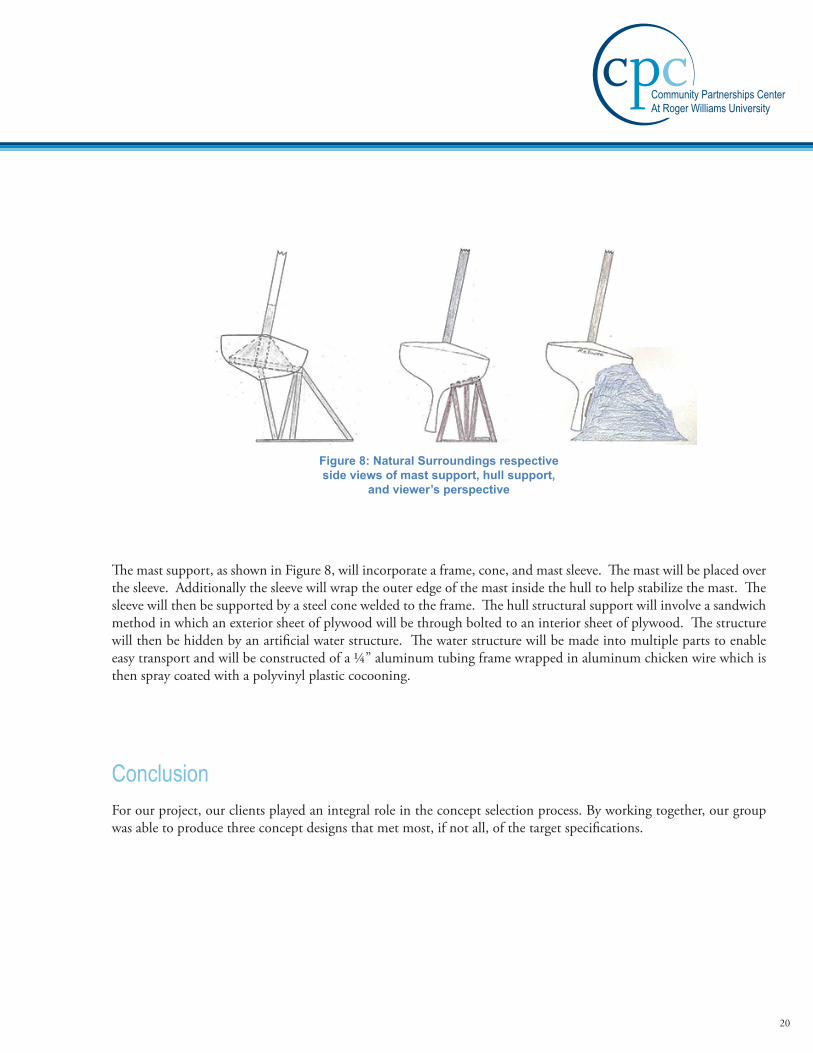
Figure 8: Natural Surroundings respective side views of mast support, hull support,
and viewer’s perspective
Themastsupport,asshowninFigure8,willincorporateaframe,cone,andmastsleeve.Themastwillbeplacedoverthesleeve.Additionallythesleevewillwraptheouteredgeofthemastinsidethehulltohelpstabilizethemast.Thesleeve will then be supported by a steel cone welded to the frame. The hull structural support will involve a sandwich method in which an exterior sheet of plywood will be through bolted to an interior sheet of plywood. The structure will then be hidden by an artificial water structure. The water structure will be made into multiple parts to enable easytransportandwillbeconstructedofa¼”aluminumtubingframewrappedinaluminumchickenwirewhichisthen spray coated with a polyvinyl plastic cocooning.
ConclusionForourproject,ourclientsplayedanintegralroleintheconceptselectionprocess.Byworkingtogether,ourgroupwas able to produce three concept designs that met most, if not all, of the target specifications.
20
Concept SelectionIntroductionEachconceptdesignhaditsstrengthsandweaknesses,sowhenwepresentedourdesignstoourclientswefoundoutwhichspecificationsweremostimportanttothem.Afteralengthydiscussionofourdesignsandclarifyinganyques-tions or concerns they had expressed, they liked the minimal exposed structure of the free floating design, and the supportanddurabilitythatthecantilevercradleoffered.Wequicklycameupwithadesignthatcombinedfeaturesof the cantilever cradle and free floating design. They seemed to like this idea, so we decided to come up with three “hybrid”designsthatincorporatedourcustomer’sadditionalconstraintsanddesires.
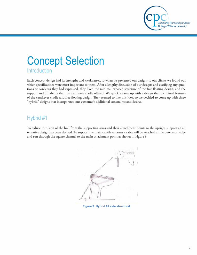
Hybrid #1To reduce intrusion of the hull from the supporting arms and their attachment points to the upright support an al-ternative design has been devised. To support the main cantilever arms a cable will be attached at the outermost edge andrunthroughthesquarechanneltothemainattachmentpointasshowninFigure9.
Figure 9: Hybrid #1 side structural
21

Atthispointthecablewillberedirectedbymeansofapulleyandattachedtothebacksidefaceoftheverticalsupport.It is at this connection point that the main stabilizer of the upright support will also be attached. The main stabilizer will consist of a tie rod that will fasten to the base plate of the cradle. The critical points of the cradle design will be foundinthetensilestressesofthesupportcableandtie-rod.Stemmingfromthisitcanalsobeassumedthattheshearstresses in the pulley through bolts and bolts at all connection locations will be substantial.
Hybrid #2OneofthemainissuesthatdevelopedwiththeFreeFloatingdesignwasportability.Duetotheanchorcablesneedinga substantial platform to be mounted to, the versatility of display locations is limited. To solve this issue and option hasbeenaddedtotheFreeFloatingdesigntogiveittheabilitytostandalone.
Figure 10: Hybrid #2 side structural
AsshowninFigure10abaseplatehasbeenaddedwhichwillprovideafoundationfortheballandsocketjointstofasten to. Two supports will attach the internal structure to the baseplate, acting as cross members. These two supports will keep the hull upright at a fifteen-degree angle and counter act the high center of gravity of the model. This design will increase the portability and versatility of the cradle design. When the model reaches its final destination in the HMMatriumthebaseplateandsupportingrodscanberemoved.Thedesignofthenewatriumshouldaccountfortherequiredanchorsupportsofthedesign,whichincludesaconcretesupportfoundationandanchoringwall.
22

Hybrid #3Hybrid#3iscombinationoftheCantileverCradlesbasesupportwiththe internalstructureoftheFreeFloatingdesign.ThemaindifferenceinthisdesignisthatthemastsupportisanextensionofthefrontbasesupportasshowninFigure11.
Figure 11: Hybrid #3 frame
Byincorporatingthemastsleeveintothebasesupport,Hybrid#3isthemostminimalstructure.Usingthelegde-sign of the cantilever cradle, the structure will also be portable since the foundation will consist of legs mounted to a baseplateandnotensioncablerequirements.
Screening and ScoringInordertoassesstheconceptdesignsonanequalplatformascreeningmatrixwasconstructed.Thescreeningmatrixenablesustoseetheadvantagesanddisadvantagesofeachdesigninasidebysidecomparison.Bydesignatingonedesign as the reference for each selection criteria and assigning it a zero, other models could then be compared to the reference by a plus or minus. The pluses and minuses for each concept were then summed to provide a score for each design,asshowninTable5.
23

Table 5: Concept Screening Matrix used to identify concepts requiring further
examination or discontinuation
Aconceptscoringsheetwasthendevisedtodetermineconceptrankingsintermsofweightedsumsonselectioncri-teria.Eachselectioncriteriawasgivenaweightedfactorontheoveralldesignandtheconceptsweregivenaratingbetweenoneandfiveastohowwelltheymeteachcriterion.Scoresforeachdesignconceptwerethenconstructedby summing the weighted scores of each criteria associated with each design, as shown in Table 6.
Table 6: Concept Scoring Matrix used to determine concept rankings
In theory, by having a weighted score assigned to each design we can determine which design best suits the needs of the client. It also enables us to decide on which design concepts to discontinue or examine further.
24

Conclusion
AfterpresentingourupdatedHybriddesignstoMr.LeeandothersatHMM,theHybrid3designwaschosenasthebestcradle.OurclientlikedtheminimalstructureandportabilitythatHybrid3offered.Italsoallowsforacomplete3600viewingperspective,withlittletonoobstructiontothepublic.ItisinterestingtonotethatinTable6,Hybrid3 also scored the highest total score.
Concept Testing PlanExecutive SummaryAconcepttestingplanhasbeendevelopedtoensurethefeasibilityandintegrityofthefinaldesign.Thefinaldesignhas been approved for further testing by both customer and design team based upon the preliminary drawings and design concepts. The testing plan is established around a series of uncertainties and risks that cannot be accurately determined from the preliminary design and dimensions. The risks and uncertainties have been further developed into aseriesofquestionswhichdriveasystemofdifferenttestsfromwhichanswerswillbeconcluded.Table3correlateseachquestiontothespecificmeansoftestingthatwillensurefeasibilityandultimatelydeemthedesignacceptable.Thepurpose,experimentalplanandscheduleforeachrespectivetestaresummedupinTable10throughTable12.Basedupontheproposedschedule,alltestingandfurtheranalysiswillbefinalizedbyDecember2nd,2012givennosignificanterrorsariseduringtesting.Fromouranalysiswewillbeabletodeterminethesizingofthestructuralcom-ponents of the cradle design and furthermore deem the overall design ready for construction.
25
Risk and Uncertainties AssessmentThe preliminary design of the final proposed concept goes into great detail to describe the methods by which the cradlewillhouseand support theReliancemodel in itsgivenorientation.However, thecradledesignhasyet toundergotheoreticalcalculationand/orSolidWorksanalysistodeterminethestructuralmember’sintegrity.Tothispointalldimensionsandmembersizinghavebeenstrictlybaseduponclearancerequirementsthatareprovidedviathehull’sgeometry.Majorrisksare foundinthemember’sabilitytoremainstructurallysoundgiventhe loadingrequirements.Toassesstheserisks,twomeansofanalysiscanbeconducted.Firstwecandeterminewhetherornotthepresentsizingwillholdthegivenload.Alternatively,wecandeterminethemaximumsizingnecessarytosupporttheloadingrequirementswhilestillallowingforafactorofsafetyof2.5.Ultimatelywearehopingthatbothsizingrequirementsandloadingneedscanbemetwiththecurrentdesign.Ifthisbecomesanissuefurtherdesignwillneedto be developed to meet the given necessities.
Giventhedesiretohavethemodeldisplayedata15degreeangle,thecradlewillundergoalargetippingforcemak-ing the entire structure want to heel over and drop. To counteract this, the cradle has been designed to work against thistippingforce.Inpreliminarydesign,differentideasweredevelopedthatwouldensurethemodelwouldnottip.Testing will allow us to determine which method will be necessary and/or if any precautions will need to be taken to alter the base of the cradle to ensure the model remains upright.
Ourultimategoalistoeliminateriskfromthedesignbydeterminingtherequirementsofthecradlegiventhefore-seeableconditionsinwhichthecradleandmodelwillbeondisplay.Atnopointcanthemodelbecomearisktothepublicand/orstaffthatwillbearoundit.Likethenameitself,Reliance, we want the designed cradle to be reliable and uphold its integrity over its lifetime.
26

Design TestingTodetermineameansoftestingtheproposedcradledesignaseriesofquestionsweredevelopedtoactasafoundationbywhichthecradlewillberated.Thequestionsasseeninthelistbelowwereestablishedfromtherisksanduncer-tainties as noted before. Once the tests and analysis have been conducted we will be able to develop answers to each questionanddeterminewhetherthedesignisindeedfeasibleorfurtheralterationstothecradleneedtobemade.
Table 7: List of questions based upon risk and uncer-tainty assessment. Each question is numbered and falls
under its specific category within the cradle design.
27

Table 8: Analyses and testing list de-veloped from needs as seen in Table 1.
28

Table 9: Comparison table linking each question to their respective means of test-ing. By testing a majority of the questions by more than one means the conclusions
that are made can be considered to be accurate
29

Testing Overview
Table 10: Theoretical Testing and Analysis.
30

Table 11: SolidWorks Modeling and Analysis.
31

Table 12: Scaled Model Prototype to determine clear-ances within hull with respect to internal structure.
ConclusionFromourtestinganalysiswewillbeabletodeterminewhetherornotthefinalproposedconceptisfeasible.Uptonowall structural analysis anddesign specificationshavebeenpurelybasedoffof theoretical concepts, clearancerequirementsdrivenbythemodel,andeducatedassumptions.Bytestingthecradledesignbymultiplemeansandmethods we are able to gain accurate insight into the unknowns and potential risks that could prove to be a hazard uponfinalconstruction.OuranalysiswillgiveboththedesignteamandtheHMMproofofintegrityandfeasibil-ity for the design enabling the project to move towards construction. In the case that the results prove the design inadequatetohandlethegivenloadingconditions,alterationswillbemadetothedesigntofixthegivenissue.Oncethe cradle is redesigned, it will be tested again by the same methods to ensure that the alterations meet the necessary conditions and fall within safety factors as specified by the client. In conjunction with structural analysis testing of theupperriggingstructure/components(tobecompletedspringsemester2013)thefinalanalysisofthecradledesignwillgiveHMMastrongfoundationfromwhichtocompletethe1/6thscaleReliance model.
32

Concept TestingExecutive SummaryThe main objective of the design was to build a cradle capable of supporting the applied loads with minimal deflec-tion. To do so, it was necessary to theoretically split the boat into multiple sections, including the upper rigging, hull, and internal structure. The weight of each section had to be calculated based on unit weight and volume of material. Aftercalculatingtheweightsandcenterofmassofeachsection,wehadtosolveforthereactionforcesactingoneachloading pad and outrigger of the cradle. Once this was complete, the sizing of the outriggers and center spine beam couldbedetermined.Oncebeamsizeswereresolved,theboltsizesrequiredtosafelyconnecteachoutriggertothecenterspineneededtobefound.Afterthesizingofallloadingmembersthatwouldbeactingonthesupportcolumnwas determined, the sizing of the support columns could be calculated to achieve the desired minimal deflection. Finally,afterverifyingthatthestructurewouldbecapableofsupportingtheappliedloads,itwasnecessarytoperformanalysis on the model as a whole to determine that the model would not be subject to tipping. The methods below explain our logic and approach used to verify the structure will be capable of safely supporting the applied load.
IntroductionAfterreceivingthespecificdesigncriteriafromourclient,ourconceptdesignswerenarroweddowntoonecradledesign. To prove the concept would work, it was necessary to perform a detailed analysis on all load bearing members toensurestructuralintegrity.Thefollowingreportexplainsthethoughtprocessandmethodsusedtoverifythequal-ity of the proposed cradle design.
33

Whendeterminingthesizeofthemembersintheinternalstructure,ananalysisofthehullwascompleted.Sincethe forces of the upper rigging are acting directly down the main mast into the forward column, there was no need to incorporate it into calculating the sizing of the beams and outriggers. The points at which the stays will be tied in will exert minimal positive load, which will reduce the deflection acting on the outriggers and therefore were excluded fromcalculations.Thedeterminationofthehull’smasswascalculatedfirstbytheuseofthehull’soriginalblueprints.The hull was separated into five sections by dividing the distances between the outriggers. This was done because the outrigger positions are specifically placed to directly connect stays or other rigging components to the cradle that would otherwise imply heavy loads into the hull. These sections were then broken into several common shapes in ordertofindthesurfaceareaofeachofthesectionsforboththedeckandrightviewoftheyacht’sblueprintsthenscaleddowntothemodel’sactualsize.Alossfactorwasappliedtothesidesectionssincetheareaswereanalyzedasifthey were flat and not curved, as the model. Then, from an assumption taken from our client regarding the thickness ofthehull(3/16”),thevolumeofeachsectionwasdetermined.Thetotalvolumewasfoundbyaddingupallthesec-tionstocreatethesolidhull.Fromthis,thepercentvolumeofboththedeckandsidewasthencalculated.ThroughtheuseofSolidWorks,theunitweightofthedensestreadilyavailablefiberglasswasobtainedandusedindeterminingthetotalmassofthehullandthemassofeachsection.Fromthisthepointloadsactingonthehullpersectionwereobtained by adding the deck and side view loads. The location of these point loads were determined by finding the centroids for each of the sections. This was done by obtaining the centroids of each of the common shapes used in determining the areas and combining them through means of geometric decomposition, where the sum of the areas multipliedbythecentroidsweredividedbythesumoftheareas.ThiscanbesummedbyEquation1displayedbelow.AnexampleoftheresultsforthisequationcanbevisualizedinFigure12.
Methods
Equation 1
Figure 12: Visual of geometric decomposition
34

Todeterminethereactingforcesactingontheoutriggerpads,thethreemomentequationwasused,asshowninEquation2.
M1L1 + 2M 2 (L1 + L2 )+M 3L2 +6A1a1L1
+ 6A2b2L2
= 6EI h1L1
+ h3L2
⎛⎝⎜
⎞⎠⎟
Equation 2
Equation2expressesageneralrelationamongmomentsatanythreepointsinabeam,henceitisknownasthethree
momentequation.Sincepoints1,2,and3areonthesamelevelinthedeflectedbeam,theheights h1 and h3 be-comezero.thereforetherighthandsideoftheequationalsobecomeszero.Thethreepointsselectedinapplyingtheequationtocontinuousbeamsarethepointsatthesupports,assumingitisarigidbody;theequationwasusedtodeterminethebendingmomentsinthebeamoverthesupports.SincetherearefivereactionforcesA-E,theequa-tionwasusedthreetimes,onceeachforA-C,B-D,andC-E.MomentsB,C,andDwerethenfoundbytheuseofmatrices.Fromthis,thebeamwasthenanalyzedagainwiththemomentsandthereactionforcesweredetermined.Sincethismethoddeterminedthereactionforcesasifitwasplaceddirectlydownthemiddleofthehull’scenterline,theforceswheretheoutriggerswereplacedweresimplydividedinhalfsinceeachoutriggerisequidistanceapartfromthe center beam. The determination of member sizing for the center beam and outriggers were calculated through meansofdeterminingthemaximumdeflection.Defelectionwasdeterminedbymethodsofintegrationofthebeamsmomentequation,withthefirstintegrationresultinginslope,andthesecondintegrationresultingindeflection.ThisishowninEquation3,Equation4,andEquation5below.
EI d2ydx2
= Moment
EI dydx
= Slope
EIy = Displacement
Equation 3
Equation 4
Equation 5
35

The longest outrigger with the largest load was checked for the chosen C-channel beam. This was analyzed as a can-tilever beam having a point load on one end and fixed on the other with a distributed load for the mass of the beam itself. In order to determine the sizing of the center beams, it was necessary to split the cradle into two separate beams since the beams are connected by a mast sleeve. There was a cantilever beam reaching out for the front support of the hull and a rear beam being dual supported. The forward beam was analyzed the same way as the outriggers except multipleforceswereanalyzed.Thereardualsupportbeamhadtobeanalyzedbyadifferentmethodsincetherewasa support roughly two thirds of the length. The reaction forces on this beam had to be determined first then analyzed instead of having a boundary condition being the whole length of the beam as if it was a cantilever beam.
When determining the sizing of the support columns, the column supporting the mast was analyzed since this will be supportingthelargestload.First,theloadsoftheentireinternalstructure,hull,andupperriggingwerecalculatedtofind the load needed to be supported. Then the load was drawn on a free body diagram to show the load acting verti-callyagainsttheangledcolumn.TheloadwasthenfoundintheXandY-directionwithrespecttothe15degreeheelangle,thex-axisrunningparalleltothemast.SincetheloadintheX-directionwasactingdirectlydownthecolumnitwasignoredandonlytheloadactingintheY-directionwasanalyzedjustasacantileverasexplainedbefore.Thedeflection was found to check that the correct sizing for the column was chosen.
The bolt sizing for the internal structure was evaluated by checking the bolt shear force on the bolt supporting the largestload.BoltshearwasdeterminedbyusingEquation6,wherethetauallowableisgivenbyusingthemaximumshearstressknownforthesizeboltandafactorofsafetyof2.5forcommonbuildingcodes.
Equation 6
Tactualwasdeterminedbytakingtheloadanddividingitbythearea.ThisisshownbelowinEquation7.ThenTactual and Tallowable were compared to check that the actual does not exceed the allowable.
Equation 7
𝝉𝝉𝑨𝑨𝑨𝑨𝑨𝑨𝑨𝑨𝑨𝑨𝑨𝑨 ≤ 𝝉𝝉𝑨𝑨𝑨𝑨𝑨𝑨𝑨𝑨𝑨𝑨 =𝝉𝝉𝒚𝒚𝑭𝑭.𝑺𝑺.
𝝉𝝉𝑨𝑨𝑨𝑨𝑨𝑨𝑨𝑨𝑨𝑨𝑨𝑨 =𝑷𝑷𝑨𝑨
36

Finally,thedeterminationofwhetherornotthemodelwouldtipwascheckedbymeansofabasictippingcalculationusing the center of mass of the upper rigging, hull, cradle, and base plate. The center of mass for the upper rigging was determinedbyfirstsettingthebottomofthemainmastastheoriginofthesystem.Afterthecentroidofeachpartoftheupperrigging(i.e.sails,booms,spars,gaff,clubs...)waslocatedwithrespecttotheorigin,theywerecombinedthroughmeansofgeometricdecompositionasdoneinEquation1.Thecenterofmassofthecradleandhullwerealready calculated and explained previously in this section. The baseplate was treated as a symmetrical shape having the center of mass directly between the two column supports. The forces applied to the center of mass of the upper rigging and hull were then combined and compared to the sum of the forces applied to the internal structure and base plate to check that the model would not tip with the applied load found.
ResultsThe results for the internal structure member sizing and load forces acting on the structure are shown below in the following tables. These results were calculated as stated above in the methods section. Table 13 and Table 14 display the results from calculating the sections of the hull from the prints. The calculations for finding the areas of the sec-tionscanbeseeninFigure13andFigure14intheappendices.Fromthisthevolumesweredeterminedandpercentvolume of the whole hull, finally determining the force acting on each section.
Table 13: Calculated weight of deck sections
37
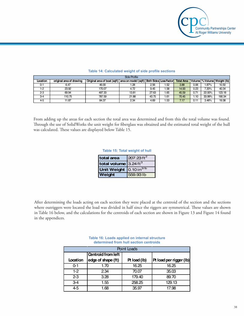
Table 14: Calculated weight of side profile sections
Fromaddinguptheareasforeachsectionthetotalareawasdeterminedandfromthisthetotalvolumewasfound.ThroughtheuseofSolidWorkstheunitweightforfiberglasswasobtainedandtheestimatedtotalweightofthehullwascalculated.ThesevaluesaredisplayedbelowTable15.
Table 15: Total weight of hull
Afterdeterminingtheloadsactingoneachsectiontheywereplacedatthecentroidofthesectionandthesectionswhere outriggers were located the load was divided in half since the riggers are symmetrical. These values are shown inTable16below,andthecalculationsforthecentroidsofeachsectionareshowninFigure13andFigure14foundin the appendices.
Table 16: Loads applied on internal structure determined from hull section centroids
38

Through the use of the three moment method explained above, the loads acting on the loading pads at the end of each outriggerweredetermined.Table17displaysthisdatahavingmember“D”havingthelargestforceof160.5lbactingoneachoftheloadingpads.ThiscalculationfordeterminingtheloadsactingonthepadsisvisualizedinFigure15andFigure16locatedintheappendices.
Table 17: load applied to each loading pad on end of outriggers
Afterdeterminingthepointloadsactingonalloutriggers,thereactionforcesofthesupportcolumnswerecalculatedand included the weight of the upper riggings. The upper rigging acting solely on the front support made it possible toonlyanalyzethatsupportsinceitwouldbesupportingahigherloadthantherearsupport.Afterdeterminingtheload applied to the support column, the angle of the force was accounted for to calculate the load that would be ap-pliedacrossthex-axisofthebeamasshowninTable18.
Table 18: determination of load ap-plied to front “mast” column
39

When checking to see if the chosen members sizing would suffice the forces that are going to be applied, the members underthemostforcewerecheckedfordeflection.Sincetheoutriggersaregoingtoallbethesamesizemember“D”waschosenanddeflectioncalculatedwasonly-4.5E-03inprovingthatthebeamselectedfortheoutriggersfortheinternalstructurearesuffice.ThiscalculationisshownintheappendicesunderFigure18.Thecheckforthecenterbeam’smembersoftheinternalstructurewasalsocheckedthroughmeansofdeflection.Therearbeamhavingthelargestloadappliedonlyincurredadeflectionof-1.34E-01inandtheforwardbeamhavingasmallerdeflectionof-8.76E-02in.ThisproofisshownintheappendicesunderFigure19,Figure20,andFigure21,wherethecalculationfor deflection is displayed. The final check for member sizing was for the mast column since the support column un-derneath the mast was supporting more of a load since the mast and upper rigging load was acting down it this was theonlycolumnnecessaryforanalysis.Aftercalculatingdeflection,whichcanbeseeninFigure23,thedeflectioncalculatedwas-3.08E-04inprovingthatthecolumnsizechosenwouldsupporttheloadactingonit.AllcalculateddeflectionspreviouslystatedaredisplayedbelowinTable19.
Table 19: chosen members and their maximum deflection
The final calculation made was the determination of the bolt size. This was done by choosing a nominal bolt size and checking the shear stress it was undergoing to the allowable shear stress that the bolt can handle. When doing this the bolt location chosen was where the most force is going to be applied. This location is where the rear center beam is
connectedtothemastsleeve.AfterdeterminingtheshearforceonthebolttheTactual was determined and compared
to the Tallowable .Sincetheactualwaslessthantheallowablethesizedboltchecksfortheappliedload.ThesevaluesareshownbelowinTable20andthecalculationsaredisplayedintheappendicesunderFigure24.
Table 20: displays the bolt shear force ex-erted on the bolt undergoing the most load
40
Discussion and Conclusion
In examining our results it was discovered that the weight of the hull was much higher than originally thought. It wasalsodeterminedthatthestrengthofsteelisveryhighandwewereabletousethesmallestofS-beams,C-channel,and box beams to hold the weight of the model. Not only will this decrease weight, but it will also decrease cost. We also learned that a boat hull is one of the hardest structures to analyze due to the unconventional shape as compared to standard structures.
The analysis of the cradle design, which meets all target specifications, has determined that it will be capable of safely supportingtheappliedloadsoftheupperrigging,hull,anditsownweight.OutriggersconstructedofC3x3.5A36steel will be capable of supporting the design load acting on the loading pads located on the outer edge of each out-riggertoprovideanacceptablelevelofdeflectionwiththemaximumbeing0.0045inches.Theoutriggerswillbeat-tachedtothecenterspinewhichwillbeAmericanStandardS3x5.7A36steelbeamsprovidingamaximumdeflectionof0.134inches.Afterdeterminingthesizingoftheoutriggersandspine,itwasdeterminedthattheoriginalplanofusinga4”x4”x.5”columnwouldbemorethancapableofsupportingtheloadasthedeflectionwouldbeminimalat.0003inches.Itwasthenverifiedthat¼”boltswouldbecapableofsupportingtheappliedloads,butforlengthrequirementsandproductavailabilityitwasdecidedtouse3/8”bolts.Afteritwasconfirmedthatthestructureisstructurally sound, a tipping calculation was done in which it was determined that in order for the cradle to tip, it neededtohaveatotalweightof2025lb.Asofnow,wearesafelyunderthatlimitat667lb.Therefore,thestructurewill stand and support all applied loads.
Lookingintothefuture,additionaltestingwillberequiredasmoreinformationcomesin.Additionaltestingwillinclude the design of the loading pads to ensure they will not puncture through the hull. The sizing of the pads can beadjustedtoachieveadesiredpressureoneachpad.Furthermore,allcalculationswerebasedonweightsdeterminedfrom unit weights and volumes of parts pulled from drawings and therefore are subject to change. The complete analysisofthecradledesignwilllikelybecompletebyMarchof2013.
41

Final SpecificationsAtthemidwaypointoftheFallsemestertargetspecificationsweresetbaseduponacompilationoftheclient’sneedsand project goals. To date, there are still numerous specifications that have yet to be finalized due to either its place-mentfallingundertheSpringschedulecompletionofworkorschedulepostponementsfromtheHerreshoffMu-seum. Many of the specifications were not critical to the scheduled completion of work for this semester and have beenhelduntilrequirednextsemester.AsforHMMdelayswearestillwaitingforthemodelhullandothermodelcomponentstobemovedtotheHerreshoffworkshopatwhichpointquantitiesforitemssuchasmodelhullweightwill be determined.
Table21displaysallofourfinalspecificationsasoftheendoftheFall2012semester.Asnotedbefore,somespeci-ficationshaveyettobeobtainedwhichisdenotedasunknowninTable1.Asnottodelayourprojectschedule,weare moving forward by making theoretical assumptions or calculated values to enter into our testing and analysis. We have conducted our testing in a manner so that once information is presented the calculations conducted prior can bere-runwiththenewnumbersinExcelformattedworksheets.Thiswillreducethetimesubstantiallytoredothecalculations with the correct values.
WhenwedevelopedasystemofmetricsbackinearlyFall,ananalysiswasgeneratedtodeterminehowwellothermodelcradlesanddesignsmetourneeds.ForthisreportwehavecreatedTable22inasimilarfashiontoratehowourdesignhasultimatelymettheclient’sneedsintheend.Thistableallowsustoseeiftherehavebeencertainneedsthatwereoverlookedand/orareasinwhichimprovementscanbemadebeforefinalizingthedesign.Atitscurrentstandings the design meets the majority of the needs with high ranks.
42

Table 21: Initial and Final Specifications for Cradle Design
Table 22: How well Final Specifications met Customer's Needs
43

Preliminary Project Cost AnalysisExecutive SummaryAt the end of the Fall 2012 semester a wide range of work has been completed that encompasses project tasks such as model cradle design and testing. During the course of this semester a final design has been generated and preliminary testing for its feasibility has been conducted. For the 2013 Winter interces-sion and Spring 2013 semester, we will be transitioning into detailed testing and analysis of both the designed cradle and Reliance model. This stage includes refining and optimizing our cradle design as well as assigning and fixing the cradle’s design details. We will be performing a structural analysis of the model’s critical components, including both theoretical analysis and failure testing to remove risk and ensure the model’s structural integrity. By the completion of the 2013 spring semester we are hoping to have all project objectives and goals completed including a finalized cradle design and structural analy-sis of the Reliance model.
Estimated CostsDuetothefactthatourportionoftheReliance project is strictly design, there are few costs associated with our work. ByacquiringvolunteerworkfromRogerWilliamsUniversityfacultyandstudents,theHereshoffMarineMuseumhas saved a substantial amount of money. Table 23 displayed below, demonstrates the costs that the museum could haveexpectedtopayiftheywereunabletoacquirevolunteerworkforthedesign.
Table 23: Estimated Labor Costs
44

The only costs we see in the future for our design team are associated with prototyping. It is expected that the cost to printa3Dmodelofthehullwillbeapproximately$320.Weestimatethatanadditional$80willbeneededfortheconstructionofacradleprototypeforatotalprototypecostofabout$400.
Attheendofourproject,weareplanningondonatinganyremainingfundstotheHMMforusetowardsthecostoftherelianceproject.SincetheHMMrunspurelyondonationsfromoutsidesources,wewouldliketobeabletohelpout as much as we can to insure the success of the reliance project and future exhibits at the museum.
Downstream Development AnalysisExecutive SummaryTheFallsemester’saccomplishmentsincludethecompletionofdesigningacradletodisplaythemodel,performingapreliminarystructuralintegrityanalysisonthefinalizeddesign,andresearchingthepotentialincorporationof3Dprintingandstructuraladhesivesintotheconstructionofthemodelboat.Duringthespringsemester,thegroupwillbeprimarilyfocusedonperformingstructuralanalysisonthemodel’scriticalcomponents,refiningthecradledesign,and completing in depth analysis of the entire structure.
Detailed DesignOne component of the project is to ensure that during the scaling down process, the fully rigged model will not fail or break. In order to accomplish this, we will be performing a structural analysis of the model’s critical components, which includes a theoretical analysis and physical failure testing to remove risk and ensure the model’s structural integrity. Some of the critical components include the blocks, halyards, and pad eyes. We will be performing failure testing on these parts by using the uni-versal testing machine located in room 119 of the School of Engineering, Computing, and Construc-tion Management at Roger Williams University. By using this machine, we will be able to determine the maximum tensile and shear force on the components to make the component yield and/or fail. By comparing our results to our theoretical analysis of the model we will be able to conclude whether the component will be able to handle the required loading conditions.
45
Asideprojectthatwaslookedintothissemesterencompassedtheideaofusingstructuraladhesivesinthemodelconstruction. The client believed that there may be an application for the use of adhesives that would make for an ease of constructability. It has been concluded that an acrylic adhesive would be best for the model boat if instituted. Sincefiberglassissimplyaglass-strengthenedplastic,aplasticbondersuchasanacrylicadhesivewouldbethebestchoice. Next semester we will be determining which specific one will be best. We have already received a free sample from the company Permabond and are hoping to test other adhesives from other companies to determine the best for the given application.
Functional PrototypeDuringthe2013winterintersession,Ericwilllookinto3Dprintinga1/90thscaleprototypeofReliance hull based uponthespecsofthefiberglasshullmadeforthemodel.Theprototype,3DprintedatR&DTechnologies,willbeapproximatelytwentyincheslongandmadeoutofaphotopolymeracrylic.Furthermore,weareplanningoncon-structing a scale model of the cradle out of balsa wood to use in conjunction with the hull. The prototypes will allow us to gain a greater sense for clearances within the closed hull as well as provide insight as to how to gain access into thehullforconstructionofthecradle’sinternalstructure.
Complete Design DocumentationUpon completion of testing and analysis of the cradle design our team will be documenting the final design to submit totheHerreshoffMarineMuseum.Thefinalcradledesignandresultsfromourstructuralanalysiswillbedocumentedin a prototype and final report, which will include design drawings and fabrication specifications. The final design results will also be communicated to our clients by an oral presentation, which will be aided by a PowerPoint deck containing results from our final report.
46

Design CompetitionsTheteamiscurrentlyplanningonenteringourcradledesign,andalltheworkwe’vecompletedforthisproject,intotwocollegiateengineeringdesigncompetitions.Thefirstone is the2013StructuralEngineeringInstitutestudentstructuraldesigncompetition.Anyteamofundergraduatecivilengineeringstudentsiseligibletosubmitastructuraldesign whose innovative project demonstrates excellence in structural engineering. Three finalist teams will be invited topresenttheirdesignsattheStructures2013CongressinPittsburg,Pennsylvania,May2nd–4th,2013.Thesub-missionisduebyJanuary15,2013.
TheseconddesigncompetitiontheteamplansonenteringistheNCEESEngineeringAward.NCEESinvitesABETaccredited programs from all engineering disciplines to submit collaborative projects that demonstrate a meaningful partnershipbetweenprofessionalpracticeandeducation.EntriesmustbereceivedbyMay6th,2013,andthegrandprizeis$25,000.
Finallyourteamwillbeenteringourdesignintothe2013RogerWilliamsUniversityAcademicShowcase.TheAca-demicShowcaseisanannualeventthatcelebratesthecreativeachievementsandinterestsofanycurrently-enrolledfull-time student. This weekend-long exhibition of student academic and co-curricular talent is held every spring and showcasessubmissionsfromfreshmanthroughseniorsinmanydifferentcategories.
ConclusionLookingforwardtothe2013Winterintersessionand2013Springsemester,weplanon3Dprintingourprototype,establishing our final specifications, finalizing our cradle design, performing structural analysis on the model, and ef-fectivelycommunicatingallofourfindingstoourclient.Asofcurrentwebelievethatallofourspecifiedgoalswillbemetontimeandwithinthebudgetallocatedtous.OurmaingoalistoeffectivelycompleteourprojecttoadegreeinwhichweareprovidingtheHerreshoffMuseumwithaperfecteddesignandassurancethattheirconstructionofthemodel will stand as the premier attraction for years to come.
47

ReferencesAmericanInstituteofSteelConstruction,comp.ManualofSteelConstruction.7thed.NewYork:AmericanInstituteofSteelConstruction,1970.Print.
Coutu."R&DTechnologies,Inc."R&DTechnologies,Inc.N.p.,2012.Web.14Dec.2012.
Elco."MetalsDepot."MetalsDepot.N.p.,2012.Web.14Dec.2012.
"HerreshoffMarineMuseum&America'sCupHallofFame."HerreshoffMarineMuseum&America'sCupHallofFame.N.p.,2012.Web.14Dec.2012.
Hibbeler,R.C.MechanicsofMaterials.UpperSaddleRiver,NJ:Pearson/PrenticeHall,2008.Print.
Hibbeler,R.C.StructuralAnalysis.England:PRENTICE-HALLINC(NJ),2008.Print.
Martin,Roger."AmericasCupYachtSculpture."AmericasCupYachtSculpture.RodgerMartinYachtDesign,2012.Web.14Dec.2012.<http://www.rodgermartindesign.com/portfolio/mfa-sculpture/>.
48

AppendicesAppendix A: Calculations
Figure 13: calculations of centroids and surface areas per hull section
49

Figure 14: calculations of centroids and surface areas per hull section continued
50
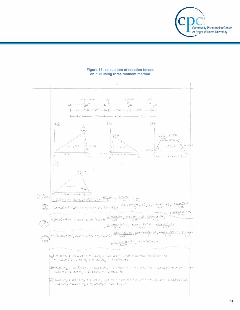
Figure 15: calculation of reaction forces on hull using three moment method
51
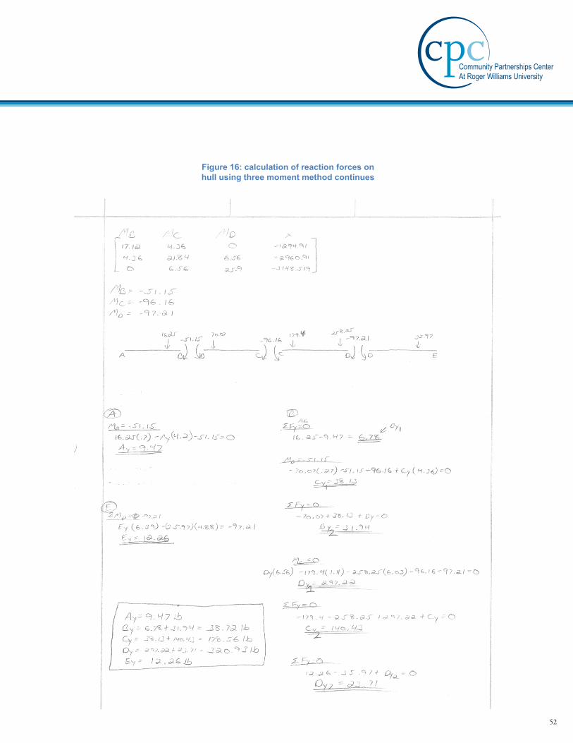
Figure 16: calculation of reaction forces on hull using three moment method continues
52

Figure 17: visual reference used to determine torque applied to outrig-
gers and center spine
53

Figure 18: calculation of deflection of outrigger undergoing largest moment
54

Figure 19: calculation of deflection of front cantilever excluding support arm
55

Figure 20: calculation of deflection on S-beam spine
56

Figure 21: calculation of deflection on S-beam spine continued
57

Figure 22: determination of largest moment applied to support column
58

Figure 23: deflection of support column supporting highest load
59

Figure 24: Determination of shear force acting on bolt
60