Reliable Dynamic Motions for a Stiff Quadruped
10
Reliable Dynamic Motions for a Stiff Quadruped Katie Byl, Alec Shkolnik, Sam Prentice, Nick Roy, and Russ Tedrake Computer Science and Artificial Intelligence Lab, MIT, Cambridge, MA 02139 [email protected], {shkolnik,prentice,nickroy,russt}@mit.edu Summary. We present a kinodynamic planning methodology for a high-impedance quadruped robot to negotiate a wide variety of terrain types with high reliability. We achieve motion types ranging from dynamic, double-support lunges for efficient loco- motion over extreme obstacles to careful, deliberate foothold and body pose selections which allow for precise foothold placement on rough or intermittent terrain. 1 Introduction Legged robots such as RHex [1] can handle many types of extreme terrain with impressive robustness, but an approach that is blind to the upcoming terrain is inherently incapable of precise foothold selection. On the other hand, position- controlled robots which are capable of precise foot placements have thus far been able to traverse significantly rough terrain only by using relatively slow, crawling gaits [10, 8, 6], typically enabled by decoupling body and leg movements, e.g., [11]. Robots such as the Raibert hopper [9] demonstrate that simple control principles can stabilize a dynamic legged machine and allow it to select foot placement on mildly rough and intermittent terrain [3]. This has been generalized for a dynamic quadruped [2] as well. However, the control problem of how to make the gaits of such robots adaptable to varying terrain has not yet been addressed adequately in the literature. There has been surprisingly little work on kinodynamic planning of underactuated gaits with the careful foot placement necessary for rough terrain on real robots. In our approach to the foothold selection and dynamic motion planning tasks for legged locomotion, we first design a family of simple, low-level motion strate- gies which can achieve either slow, careful footsteps or fast, dynamic motions, as required by the upcoming terrain. A high-level planner can then select from among these low-level options to obtain an appropriate trade-off between speed and accuracy to travel across rough terrain. The platform we use to demonstrate this approach is a small, point-footed quadruped robot called LittleDog, which is made by Boston Dynamics and is currently used as part of the DARPA-sponsored Learning Locomotion project. The goal of the project is to develop a walking controller which enables the robot to traverse a variety of rough terrain both quickly and robustly. The LittleDog robot has 12 motors with large gear ratios, two at each hip and one at each knee. O. Khatib et al. (Eds.): Experi. Robotics: The 11th Intern. Sympo., STAR 54, pp. 319–328. springerlink.com c Springer-Verlag Berlin Heidelberg 2009
Transcript of Reliable Dynamic Motions for a Stiff Quadruped

Reliable Dynamic Motions for a Stiff Quadruped
Katie Byl, Alec Shkolnik, Sam Prentice, Nick Roy, and Russ Tedrake
Computer Science and Artificial Intelligence Lab, MIT, Cambridge, MA [email protected], {shkolnik,prentice,nickroy,russt}@mit.edu
Summary. We present a kinodynamic planning methodology for a high-impedancequadruped robot to negotiate a wide variety of terrain types with high reliability. Weachieve motion types ranging from dynamic, double-support lunges for efficient loco-motion over extreme obstacles to careful, deliberate foothold and body pose selectionswhich allow for precise foothold placement on rough or intermittent terrain.
1 Introduction
Legged robots such as RHex [1] can handle many types of extreme terrain withimpressive robustness, but an approach that is blind to the upcoming terrain isinherently incapable of precise foothold selection. On the other hand, position-controlled robots which are capable of precise foot placements have thus far beenable to traverse significantly rough terrain only by using relatively slow, crawlinggaits [10, 8, 6], typically enabled by decoupling body and leg movements, e.g.,[11]. Robots such as the Raibert hopper [9] demonstrate that simple controlprinciples can stabilize a dynamic legged machine and allow it to select footplacement on mildly rough and intermittent terrain [3]. This has been generalizedfor a dynamic quadruped [2] as well. However, the control problem of how tomake the gaits of such robots adaptable to varying terrain has not yet beenaddressed adequately in the literature. There has been surprisingly little workon kinodynamic planning of underactuated gaits with the careful foot placementnecessary for rough terrain on real robots.
In our approach to the foothold selection and dynamic motion planning tasksfor legged locomotion, we first design a family of simple, low-level motion strate-gies which can achieve either slow, careful footsteps or fast, dynamic motions,as required by the upcoming terrain. A high-level planner can then select fromamong these low-level options to obtain an appropriate trade-off between speedand accuracy to travel across rough terrain.
The platform we use to demonstrate this approach is a small, point-footedquadruped robot called LittleDog, which is made by Boston Dynamics and iscurrently used as part of the DARPA-sponsored Learning Locomotion project.The goal of the project is to develop a walking controller which enables the robotto traverse a variety of rough terrain both quickly and robustly. The LittleDogrobot has 12 motors with large gear ratios, two at each hip and one at each knee.
O. Khatib et al. (Eds.): Experi. Robotics: The 11th Intern. Sympo., STAR 54, pp. 319–328.springerlink.com c© Springer-Verlag Berlin Heidelberg 2009

320 K. Byl et al.
Fig. 1. LittleDog walks carefully on pegs
The high gear ratios (85:1) make the joints so stiff that the robot can hold itsown weight in an upright stance even when the power is switched off. The bodyhas a mass of 1.8 kg, which is significantly greater than the mass of each leg(at 0.25 kg). The robot has a variety of sensors which include (most notably)encoders at each of the 12 joints, an IMU, 3-axis force sensors at each foot,and current, voltage and temperature sensors. Additionally, it operates withina Vicon motion capture (mocap) environment which provides 6-DOF positioninformation for the robot body and for the terrain with a 50 ms latency; a sub-millimeter accuracy terrain map is provided. The robot has a 1 kHz internal PDcontrol loop on desired joint trajectories. All other control is done by an externalcomputer in a 100 Hz loop through a wireless connection.
When exact foot placement is critical, we can use the stiff joints of the robotto position the body and legs carefully, as shown in Figure 1. For more dynamicmotions, the velocity and power limits do not allow for a truly ballistic, airborne“jump”. However, by carefully planning the desired ground reaction forces, wecan achieve repeatable, bipedal “lunging” motions which allow the front legs toclear gaps or vertical obstacles or to initiate a climb where there is a step interrain height, as depicted in Figures 2, 5 and 8.
Fig. 2. LittleDog climbs a step dynamically
2 Technical Approach
Planning ground reaction forces is central to our methodology. For slow motions,such as the peg-walking in Figure 1, we use the standard, quasi-static crawlinggait [7] in which the projection of the center of mass (COM) of the robot isalways within the support polygon. Slow walking is performed sequentially byfirst moving the body into a 3-legged support polygon and then moving theremaining “swing” leg.
Reliable Dynamic Motions for a Stiff Quadruped 321
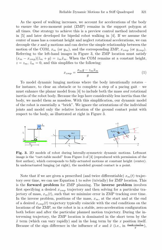
As the speed of walking increases, we account for accelerations of the bodyto ensure the zero-moment point (ZMP) remains in the support polygon atall times. One strategy to achieve this is a preview control method introducedin [5] and later developed for bipedal robot walking in [4]. If we assume thecenter of mass has a constant height and neglect rotational accelerations, we candecouple the x and y motions and can derive the simple relationship between themotion of the COM, xm (or ym), and the corresponding ZMP, xzmp (or yzmp).Referring to the left-hand images in Figure 3, the ZMP location must satisfy(xm − xzmp)(zm + g) = zmxm. When the COM remains at a constant height,z = zm, zm = 0, and this simplifies to the following:
xzmp =xmg − zmxm
g(1)
To model dynamic lunging motions where the body intentionally rotates –for instance, to clear an obstacle or to complete a step of a pacing gait – wemust enhance the planar model from [4] to include both the mass and rotationalinertia of the robot body. Because the legs have considerably less inertia than thebody, we model them as massless. With this simplification, our dynamic modelof the robot is essentially a “brick”. We ignore the orientations of the individualjoints and model only the relative location of the ground contact point withrespect to the body, as illustrated at right in Figure 3.
m, Jz
m
xm
gL
1
L2
m, Jα
θ1
θ2
x
z
g
(xm
,zm
)
Fig. 3. 2D models of robot during laterally-symmetric dynamic motions. Leftmostimage is the “cart-table model” from Figure 3 of [4] (reproduced with permission of thefirst author), which corresponds to fully-actuated motions at constant height (center).In underactuated lunging (at right), the modeled ground contact is a point.
Note that if we are given a prescribed (and twice differentiable) xm(t) trajec-tory over time, we can use Equation 1 to solve (trivially) for ZMP location. Thisis the forward problem for ZMP planning. The inverse problem involvesfirst specifying a desired xzmp trajectory and then solving for a particular tra-jectory of mass, xm(t), such that we minimize error in ZMP tracking over time.In the inverse problem, positions of the mass, xm, at the start and at the endof a desired xzmp(t) trajectory typically coincide with the end conditions on thelocations of the ZMP, so the robot is in a stable, zero-acceleration configurationboth before and after the particular planned motion trajectory. During the in-tervening trajectory, the ZMP location is dominated in the short term by thex term (which can vary rapidly) and in the long term by the x position itself.Because of the sign difference in the influence of x and x (i.e., in xmg−zmxm
g ),

322 K. Byl et al.
these short-term and long-term goals are at odds; we will generally have to shiftthe ZMP in the opposite direction from our eventual goal. There are a varietyof ways to solve control problems of this type; the preview control solution [5, 4]is simply the one we prefer to use.
The preview control method augments this inherently second-order system(i.e., a simple mass and inertia being pushed around) by including accelerationas an additional state. By using acceleration as a state variable, we can createa state-space model which has the ZMP itself as a desired output, and we canthen use a linear-quadratic cost – mostly on the desired output, with a smalladditional cost on actuation effort – to solve for the required x trajectory overtime which will minimize our cost function. Performing this for both (x, z) and(y, z) relationships independently results in a way to generate x(t) and y(t)trajectories automatically for whatever overall speed we deem prudent, basedon how rough the terrain is.
What is exciting and somewhat unexpected is that we can also plan double-support motions reliably using this same, basic preview control strategy. For adynamic lunging motion, there is no longer a support polygon, since the robot bal-ances precariously on just two feet during a motion. Our planning now requires aZMP which is precisely on the line connecting these two feet for a short duration(about 0.3 sec). We will simultaneously open the inter-leg angle between the sup-port legs and the body quickly during our ZMP-balancing time window. Figure 3(right) illustrates such a motion with a 2D planar model. Although rotational ac-celerations now clearly violate our assumptions in Equation 1, pinning the grossmotion of the center of mass to the idealized preview control solution in fact goesa long way toward decoupling the calculations for the x motion of the body versusits orientation angle, α: the overall motion of the mass in x essentially balancesan inverted pendulum system. Commanding an additional hip angle on top of thenominal motions obtained from the inverse kinematics solution for the x motiongenerates an additional, rotational momentum. This motion acts to destabilizethis planned equilibrium, but if these motions are commanded to happen rapidlyenough, then 1) the body successfully does pitch upward and 2) the additional mo-ments caused by pitching the body shift both the COM and the “fictitious ZMP”forward of the line of double-support stance, stabilizing the total motion to ensurethe robot lands by falling forward rather than backward.
Similar tactics are employed to achieve a fast, stable dynamic walking gait.When walking, we utilize a “diagonal” gait, in which a single body movement ac-companies two leg steps: a front leg step, followed by a back leg on the diagonally-opposing side. As the body accelerates from rest to the front swing foot, the ZMPmoves in the direction opposite the acceleration. By design, the ZMP still re-mains within the support triangle, however. As the body decelerates with thefront leg still in the air, the robot enters a brief double-support phase duringwhich it is rocked onto the front foot which is about to touch down. The entiremotion produces a fast gait and ensures that feet are unloaded before they arelifted off the ground, enhancing the dynamic stability of the system and allowingfor dynamic walking over rough terrain.

Reliable Dynamic Motions for a Stiff Quadruped 323
0.5 1 1.5−0.05
0
0.05
0.1
0.15
Time (sec)
Loca
tion
in x
(m
)Preview Control Solution
Step transitionCOM trajectoryZMP trajectory
−0.2 0 0.2 0.4 0.6 0.8−0.05
0
0.05
0.1
0.15
Time (sec)
Loca
tion
in x
(m
)
Tcom
= 0.4 sec
Step transitionCOM trajectoryZMP trajectory
Fig. 4. The inverse (left) and forward (right) problems ZMP trajectory
At left in Figure 4 is an example of a solution to the inverse problem for the1D motion of a point mass which is at a height of zm = 0.135 m; the previewcontrol model used is described in more detail in [4]. The desired ZMP trajectoryin this example is a step function, going from 0 to 0.1 m at t = 1 second. Thecenter of mass moves monotonically from the 0 to 0.1 m while the ZMP exhibitssome overshoot, going somewhat outside of this 0-0.1 m range. The magnitudeof the overshoot in ZMP is only about 5 mm while the distance to the edge ofthe support polygon is typically on the order of 5 cm (10x further). However,there are two significant penalties to be paid for such an overly-cautious solution.First, calculating the inverse solution in real-time is computationally expensive,which would result in significant pauses between steps on the real robot. Second,the actual time required to move the mass is significantly slower (approximately1.0 seconds) than it needs to be. To optimize our speed in fast walking, wedeliberately plan for more aggressive excursions of the ZMP to achieve motionsof the mass which are approximately twice as fast as the inverse solution shownin Figure 4. The solution we use is a smooth half-cosine wave shape motion forthe mass, timed such that the ZMP moves nearly as cleanly from one supportpolygon to the next as for the inverse solution while overshoot (i.e. extra push-off and braking by the stance legs) is allowed for additional speed. At right inFigure 4 is a forward solution of the following form:
xm = x0 + (xf − x0) ∗ 1/2 ∗ (1 − cos(π/Tcos)) (2)
where x0 and xf are the initial and final positions of the mass, respectively.Note that both the trajectories of both xm and xzmp are each half-cosine waves.From Equation 1, we find that the peak overshoot in ZMP occurs for the masstrajectory in Equation 2 comes at both t = 0 and at t = Tcos. Solving for thediscursion of the ZMP at t = 0, we find:
xzmp(0) =−zm
gxm =
−zm
g
(xf − x0)2
(π
Tcos
)2
(3)

324 K. Byl et al.
3 Results
We apply the dynamic locomotive behaviors described in the previous section tonegotiate a wide variety of terrain type. Some examples are shown in Figure 5.We calculated the average speed of crossing the terrains as the robot moves fromstart to goal over a distance of 1.2 meters. The speed ranged from 5.6 cm/sec(for very rocky terrain) to 12.5 cm/sec when walking on flat terrain. For a senseof scale, the leg length is approximately 16 cm when fully extended and about12 cm in a nominal stance pose with a slight bend at the knee. The body isapproximately 20 cm in length.
There are two classes of terrain in which our method yields the most sig-nificant speed improvement over a crawl gait solution. One is for intermittentobstacles, including the thin, vertical (“jersey”) barriers and the gap obstacles,as illustrated in Figure 5. Here, swinging both front legs over the obstacle in adouble-support lunge allows us to perform at over twice speed of a statically-stable crawl. The second type of terrain where dynamic planning greatly im-proves speed is for rough terrain where a) footholds are flat enough to avoidsignificant slippage and b) the path between footholds do not present signifi-cant vertical obstacles. Here, there is little risk of collisions with terrain featureswhich would knock us off course during an open-loop trajectory; we cross suchrough terrain at over 80% of our speed on flat terrain.
Fig. 5. LittleDog traversing various terrain dynamically
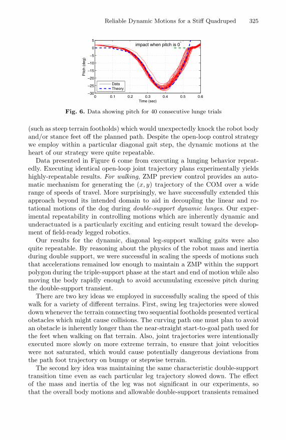
In addition to the speed benefits of planning dynamic, double-support motionson the terrain types mentioned, we also report significant reliability. For theterrain types where we plan for the fastest speeds (gaps, jersey barrier andmodular boards), we observe success rates at or above 95% at top speeds. Forsuch terrain, it is worth noting that success requires appropriate clearance ofthe upcoming obstacle and joint trajectories that are not near the saturationlimits (primarily in joint velocity). For example, although the peak angle ofpitch during a double support lunge had some variability, as shown in Figure 6,the duration of the motion was repeatable enough to ensure we attained ourdesired end pose as the robot rotated back onto all four feet after clearing anobstacle. The problems of finding mid-air trajectories for the non-support feetwhich would avoid collisions and would end in an appropriate configuration atlanding were relatively simple, as compared with planning the dynamic motionsof robot body and the corresponding joint trajectories for the two legs used indouble support. For fast, double-support walking, repeatability also dependedcritically on avoiding unexpected collisions with the terrain or other situations
Reliable Dynamic Motions for a Stiff Quadruped 325
0 0.1 0.2 0.3 0.4 0.5 0.6−30
−25
−20
−15
−10
−5
0
5
impact when pitch is 0°
Time (sec)
Pitc
h (d
eg)
DataTheory
Fig. 6. Data showing pitch for 40 consecutive lunge trials
(such as steep terrain footholds) which would unexpectedly knock the robot bodyand/or stance feet off the planned path. Despite the open-loop control strategywe employ within a particular diagonal gait step, the dynamic motions at theheart of our strategy were quite repeatable.
Data presented in Figure 6 come from executing a lunging behavior repeat-edly. Executing identical open-loop joint trajectory plans experimentally yieldshighly-repeatable results. For walking, ZMP preview control provides an auto-matic mechanism for generating the (x, y) trajectory of the COM over a widerange of speeds of travel. More surprisingly, we have successfully extended thisapproach beyond its intended domain to aid in decoupling the linear and ro-tational motions of the dog during double-support dynamic lunges. Our exper-imental repeatability in controlling motions which are inherently dynamic andunderactuated is a particularly exciting and enticing result toward the develop-ment of field-ready legged robotics.
Our results for the dynamic, diagonal leg-support walking gaits were alsoquite repeatable. By reasoning about the physics of the robot mass and inertiaduring double support, we were successful in scaling the speeds of motions suchthat accelerations remained low enough to maintain a ZMP within the supportpolygon during the triple-support phase at the start and end of motion while alsomoving the body rapidly enough to avoid accumulating excessive pitch duringthe double-support transient.
There are two key ideas we employed in successfully scaling the speed of thiswalk for a variety of different terrains. First, swing leg trajectories were sloweddown whenever the terrain connecting two sequential footholds presented verticalobstacles which might cause collisions. The curving path one must plan to avoidan obstacle is inherently longer than the near-straight start-to-goal path used forthe feet when walking on flat terrain. Also, joint trajectories were intentionallyexecuted more slowly on more extreme terrain, to ensure that joint velocitieswere not saturated, which would cause potentially dangerous deviations fromthe path foot trajectory on bumpy or stepwise terrain.
The second key idea was maintaining the same characteristic double-supporttransition time even as each particular leg trajectory slowed down. The effectof the mass and inertia of the leg was not significant in our experiments, sothat the overall body motions and allowable double-support transients remained

326 K. Byl et al.
Fig. 7. Predicted pitching (nose-down) motion during double support phase
essentially constant (at about 0.25 sec in duration) over the various terrainboards we tested. Our most significant speed improvements from using thisdynamic double-support gait came when the quarter-second transition was asignificant fraction of a two-legged motion, but the same reasoning allowed forsteady, repeatable walking over a wide range of overall speeds on rough terrain.
4 Discussion
Many of the most successful bipedal robots to date (e.g., Honda’s ASIMO,Kawada’s HRP-2, and KAIST’s Hubo, to name a few) are based on motionplanning and feedback stabilization strategies which regulate the zero-momentpoint (ZMP) of the ground reaction forces to be safely inside the supportingpolygon. This regulation is accomplished with high-gain servo motors, but isaided by direct measurements of the ground reaction forces through load cellsin the feet. The methods presented here can be interpreted as extending theZMP-style motion planning into dynamic regimes where the supporting polygonis a line, and the distance between the ZMP and the edge of the support polygon(aka the ZMP-margin) is at best identically zero.
Perhaps the most important lesson here is that this reasoning about groundreaction forces proved to be relevant and powerful despite the fact that our robotwas seemingly missing all of the prerequisites for force control. Specifically, recallthat commands here were delivered over a low-bandwidth (100 Hz) commandinterface to highly-geared (stiff) position-controlled joints on the robot. Further-more, we did not have an accurate dynamic model of the robot, nor accurate forcesensors in the feet; no load cell feedback was used in generating these motions. Infact, it is the gross motion of the center of mass that dominates the productionof ground reaction forces, and desired center of mass trajectories can be trackednicely with stiff position control. This idea is presumably well-understood bythe ZMP-walking community, but is perhaps an under-appreciated aspect of thesuccess of their robots.
5 Future Work
Our future aim is to plan for arbitrary final footholds for the front feet and(especially) for initial footholds. Figure 8 shows LittleDog climbing particu-larly extreme terrain, using the same lunge used to climb a step (Figure 2).

Reliable Dynamic Motions for a Stiff Quadruped 327
Fig. 8. LittleDog using a dynamic lunge to get onto elevated rough terrain
This sequence currently executes with approximately 70% reliability. Our cur-rent dynamic climbing motion also requires that all four feet of the dog areinitially on flat, even terrain. A significant goal in generalizing foothold selec-tion is to achieve bounding over rough terrain. This task is particularly difficultbecause the front and back feet have wide separation, meaning significant en-ergy is lost in impact when the front feet of our non-compliant quadruped hitthe ground.
6 Conclusions
In this paper, we present a reasoned approach for planning highly-repeatabledynamic motions for a quadruped robot which lacks either passive complianceor sensory feedback bandwidth – two typical approaches for achieving dynamicgaits. Instead of using such natural or control-based compliant dynamics, wereason about a simplified physical model of the robot body to design plannedground forces and body motions which are compatible for underactuated, double-support phases in motion. If saturation limits (primarily in velocity) of the robotare carefully avoided, the high impedance of the robot ensures that plannedjoint trajectories are executed with high fidelity, and planned underactuatedtrajectories result in good repeatability over each short (0.3 sec) double-supportphase. Interspersing double-support phases with three-legged support periodi-cally corrects for any small deviations (e.g., in pitch) to keep the overall trajec-tory of the robot near a higher-level set of pre-planned, nominal gait poses. Thisstraight-forward strategy allows us to negotiate significant examples of roughterrain (gaps, hurdles, etc.) at over twice the speed of a traditional “crawl” gait.Equally significant and perhaps less intuitively, we obtain more reliable resultsby using this careful reasoning about the ground reaction forces and body mo-tions than in using a crawl gait. Although, a crawl gait is often assumed to be a“conservative” strategy on rough terrain, violations of the static assumption andswing-leg collisions with terrain become more probable as speed increases – bothresulting in unexpected moments which may topple the robot. Our approachprovides a practical solution to the dual goals of increasing both speed andreliability of locomotion while also enabling efficient negotiation of significantterrain obstacles.

328 K. Byl et al.
References
1. Altendorfer, R., Moore, N., Komsuoglu, H., Buehler, M., Brown Jr., H.B., Mc-Mordie, D., Saranli, U., Full, R., Koditschek, D.E.: RHex: A biologically inspiredhexapod runner. Autonomous Robots 11(3), 207–213 (2001)
2. Buehler, M., Playter, R., Raibert, M.: Robots step outside. In: Int. Symp. AdaptiveMotion of Animals and Machines (AMAM), pp. 1–4 (2005)
3. Hodgins, J., Raibert, M.: Adjusting step length for rough terrain locomotion. IEEETrans. on Robotics and Automation 7(3), 289–298 (1991)
4. Kajita, S., Kanehiro, F., Kaneko, K., Fujiware, K., Harada, K., Yokoi, K.,Hirukawa, H.: Biped walking pattern generation by using preview control of zero-moment point. In: Proc. of the IEEE International Conference on Robotics andAutomation (ICRA), September 2003, pp. 1620–1626 (2003)
5. Katayama, T., Ohki, T., Inoue, T., Kato, T.: Design of an optimal controller fora discrete-time system subject to previewable demand. International Journal ofControl 41(3), 677–699 (1985)
6. Zico Kolter, J., Rodgers, M.P., Ng, A.Y.: A Control Architecture for QuadrupedLocomotion Over Rough Terrain. In: Proc. of the IEEE Int. Conf. on Robotics andAutomation (ICRA), pp. 811–818 (2008)
7. McGhee, R.B., Frank, A.A.: On the Stability Properties of Quadruped CreepingGaits. Mathematical Biosciences 3, 331–351 (1968)
8. Pongas, D., Mistry, M., Schaal, S.: A Robust Quadruped Walking Gait for Travers-ing Rough Terrain. In: Proc. of the IEEE Int. Conf. on Robotics and Automation,ICRA (2007)
9. Raibert, M.H.: Legged Robots That Balance. The MIT Press, Cambridge (1986)10. Rebula, J., Neuhaus, P., Bonnlander, B., Johnson, M., Pratt, J.: A Controller for
the LittleDog Quadruped Walking on Rough Terrain. In: Proc. of the IEEE Int.Conf. on Robotics and Automation, ICRA (2007)
11. Shkolnik, A., Tedrake, R.: Inverse kinematics for a point-foot quadruped robotwith dynamic redundancy resolution. In: Proc. of the IEEE Int. Conf. on Roboticsand Automation (ICRA) (2007)