Relations between UML diagrams - sinf.ase.ro - Curs 8 System Design - engl.pdf · diagram to focus...
50
Relations between UML diagrams
Transcript of Relations between UML diagrams - sinf.ase.ro - Curs 8 System Design - engl.pdf · diagram to focus...

Relations between UML diagrams

Re-iterate and improve Analysis model.
Analyze dependencies between diagrams.
Build a design model of a computer system, considering various architecture types.
Agenda

Modeling purpose
After system analysis, we proceed with system
modeling (or design) in order to:
Facilitate the correct understanding of the system;
Remove information an operation redundancy;
Reduce the run time for various queries and updates of
database;
Reduce the customer waiting time.

Realizarea cazurilor de utilizare
Design and implementation of use cases
Sequence diagram– it is expanded starting from the system sequence diagram, adding a controller and domain classes;
Design class diagram– it is expanded starting from the domain classes model and updated based on sequence diagrams Messages (calls) that are received by an object should become methods of that
class Class definitions– they are written in the programming language chosen for
implementation of design and controller classes. User interface classes– forms or pages added to manage user interface between
actors and controller classes. DB access classes– they are added to manage requests for querying or saving data
into the DB
Detailed design of the static model A detailed version of the class diagram is designed, including navigation visibility
for associations. Based on the sequence diagrams, the signature of the class methods is completed The solution is partitioned in packages (grouping elements), as deemed necessary
Design class diagram
Stereotypes are added for classes Persistent class– a class whose objects have to exist after
the system is turned off Entity class– an identifier for a problem domain class. Boundary / view class – a class that is situated at the
automated boundary of a system, such as in input form or a Web page
Control class – a class that mediates between boundary and entity classes, acting as a control panel between user level (visualization) and business level
Data access class– a class that is used to receive or send data from/to a database

Navigation visibility
It is an object ability to view and interact with another object
It is implemented by adding into a class a object reference variable;
It is symbolized as an arrow on one of the association ends – Client can view and interact with Sale

Navigability rules
One-many association that indicates a superior-subordinate relationship ensures navigation from superior to subordinates
Mandatory associations in which objects of a class cannot exists without objects of another class, usually provide navigation from the most independent class to the most dependent one.
When an object needs information from another object, a navigable association might be necessary
Detailed Class Diagram
Go through the use cases
Select the domain classes that are involved in each use case; Check the preconditions and postconditions for their completion.
Add a controller class to be responsible for the use case
Determine the requirements for navigation visibility
Fill in the attributes of each class with visibility and type
Note: Many times multiplicities are removed from the diagram to focus on navigation, but they can be retained


Class Methods
You can use the CRC - Class, Responsibility, Collaboration cards technique
What are the responsibilities of a class and how it collaborates with other classes to realize the use case
It is obtained through brainstorming
You can use detailed sequence diagrams - each message received by an object of a class must have a corresponding method in that class

CRC examples


Protection against change
A design principle is to separate the parts that are stable from the parts that undergo numerous changes.
Separate forms and pages in the user interface that have a high probability of changing from the logic of the application.
The connection to the database and SQL logic that are likely to change is kept in separate classes from the application logic
Use adapter classes that can change for interaction with other systems
If you choose between two design variants, choose one that offers greater protection against change
Design of the database
It starts from the class model
The structure of the database is selected
Typically we work with relational databases, but there may be platforms that work with object-oriented databases
Designing the DB architecture (distributed, etc)
Design the schema of the database (Entity Relationship Diagram)
Tables and columns in relational model
Design the referential integrity constraints
References through external keys

Designing the interfaces
After completing the use case diagrams and the first stable version of interaction and classes diagrams are developed, it is recommended to implement a prototype of the IT system.
This prototype is called interface prototype because it has the role to:
Refine the relationships between actors and interface classes;
Obtain feedback from the client (client) on the visual aspect of the application.

Designing the interfaces
The first step - investigating the actors' expectation on the interface by completing specific questionnaires consisting of the following questions: What level of training (computer science) the actor
requires to achieve a certain functionality?
Does the actor have working experience in window-based environments?
Does the actor have experience in using other automated process modeling systems?
Is it necessary to consult documents / catalogs in parallel with the use of the application?
Does the actor want to implement 'rescue / restoration' facilities?

Designing the interfaces
The goals of the prototype are:
Setting interface requirements for key application functionalities;
It demonstrates to the client (in a visual form) that the project requirements have been well understood and are achievable;
The start of the development phase of the standard interface elements.
Designing the interfaces
Screen structure maps (charts) are used to describe the flow of the application following the main ways of use.
Representation :
Square shapes for modal window representation (requires a user response to continue an activity).
Square shapes with rounded corners for the representation of non-modal windows
The crossing direction shows the window navigation path.

Windows that contain Tabs
Screen structure diagram
Main window
Class management
Search teacher
Search student

Use case modeling

Modelarea cazurilor de utilizare
It was modelled a central use case that describes situations when receptionists interact with the software application. This use case groups the actions of hotel staff.
It differs from the initial model that included two main groups of activities, the latest includes 5 groups: 1. Login;
2. Booking management;
3. Pre-arrival reports and documents;
4. Accommodation management;
5. Other reports.

Use case: Login
This use case refers to the process of accessing the application.
According to this use case, the only people who can access the application are the authorized persons to whom the user name and password have been communicated

Detail: Booking management

Use case modeling(2)
The initial use cases: Booking request and şi Finding available rooms have been merged in the case called Booking- Availability check..
Actor- Receptionist
he deals with receiving booking requests, requests expressing customer choices.
In this situation, the interaction of the actor with the system consists in consulting the availability of rooms by checking whether the requested type of accommodation is possible during the mentioned period.
Thus, the actor offers a prompt response, without losing time with information and checks.

Use case modeling(3)
Initial use case: Request Acceptance / Rejection and Documentation on booking details are merged now into one use case.
Practically, the only responsibility of the staff is to provide the application with the booking data.
Updating of availability is done automatically, and filling in that log is no longer required for obvious reasons.

Use case modeling(4)
In various situations, it may be necessary to change the dates of a booking: arrival date or departure date. in case of non-payment of the guarantee, the reservation state is
changed from guaranteed to non-guaranteed, it is possible to change the arrival time limit.
Also, a reservation can be canceled. These two cases resulted from the original Document Management
use case. Unlike the original model, that manual placement of bookings is no longer done because it is not necessary.
Also, there is no need to complete that Modification-Cancellation Form. The actor only needs to make the appropriate modification or cancellation, and the availability will update automatically.
Update client data is a new created use case because customer information will be retained and changes to customer data may occur

Detail: Pre-arrival reports and documents

Use case modeling(5) This case of use was created as a result of modeling two initial cases: Reservation Report
Processing and Preparing for Customers Arrival. We have a more complex case that highlights a lot of possibilities for the actor to interact with the computer application.
A new use case where the actor - Receptionist staff - interacts with the system to get reports for maids on the rooms to be cleaned.
Another case that is the result of returning of reports by the maids with the strict descriptions of clean rooms. Thus, the reception staff changes the status of the corresponding room: clean / unclean.
The actor can request and get an exact situation with the state of rooms at any time. The rooms may be free / clean (ready to be distributed), free / uncleaned (also called "checked-out", require at least 30 minutes to be cleaned), occupied, blocked.
Another necessary information for the reception staff is the Arrivals and Departures List, which the actor can also get at any time, without losing time by checking those booking forms.
Guaranteed reservation list on the expected arrival of the next day will be issued at 08.00 every day for transmission to the accounting department. The updated list must be returned by 22.00 the same day. At 22:00, updates are made. Where applicable, guaranteed reservations become non-guaranteed. Staff interaction with the system at this step can be seen in the use of Modify Booking.

Detail: Accommodation management

Use case modeling (6)
Client Registration and Room Assignment have become one, as the assignment of the camera, (and the status change) is done automatically without requiring the actor's direct involvement.
Client recording is primarily a legal requirement. If a customer who has a reservation is registered, then the necessary data already exists. For walk-in customers, registration information is provided to the system.
For walk-in clients, the reception staff must also update the availability of the rooms during the client's stay, in order to avoid overbooking.
Whether it is a customer with reservation (who paid partially or fully for the stay) or a walk-in client, at the time of delivery of the key, the payment must be made in full. The money is collected by the reception staff and a receipt is issued.
It is checked whether the departure date is the date announced, and if not, the necessary adjustments are operated and the room state is changed to free / uncleaned.

Static structure modeling
After analysis, it was decided to renounce to some classes and introduce others. Booking request disappears due to the fact that it is no longer useful. The Booking form is the only document that contains all the relevant information about a potential customer and his / her request for accommodation. Also, many of the information in the form is entered in the hotel log, which means more time consuming.
Information about hotel customers are needed, so a new classes appear: Client and Booking, and the Log class disappears.
The Booking diagram turns into Availability, Room and Room type that does not keep track of all rooms, but only the total number of rooms of each type.
The Modification/ Cancelation form also disappears as new attributes will be entered in the Booking class to allow the cancellation operation and new methods to allow for changes to the booking.
The Registration form becomes Registration that has fewer attributes, because by creating the client class, certain information is no longer duplicated.
Also, two classes have been introduced User and Who, classes used to access the application or to monitor access to the application.

Class model

Dynamic structure modeling
• The staff must login before querying or updating information. This way, it is possible to know who has accessed the application, and in case of errors it's known why the error occurred.
• The user-password combination is validated. • Depending on the response, access to the application is accepted or
not.

Booking management– Avalability check
• Before making a reservation or a walk-in client registration, reception personnel must check if the required room type is available for the required date.
• Depending on system response for availability check, a client response is also offered

Accepting booking request
• When a positive response is given to the customer, we proceed to booking registration.
• The first step is to verify the existence of the customer. If it does not exist, its data will be saved.
• The booking itself is then recorded. • At the time of automatic save, the availability for the required days and
type of room will be decremented.

Activity diagram: Login
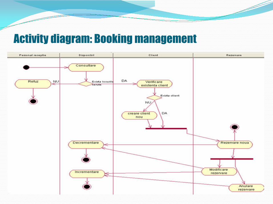
Activity diagram: Booking management

Activity diagram: Pre-arrival reports and documents
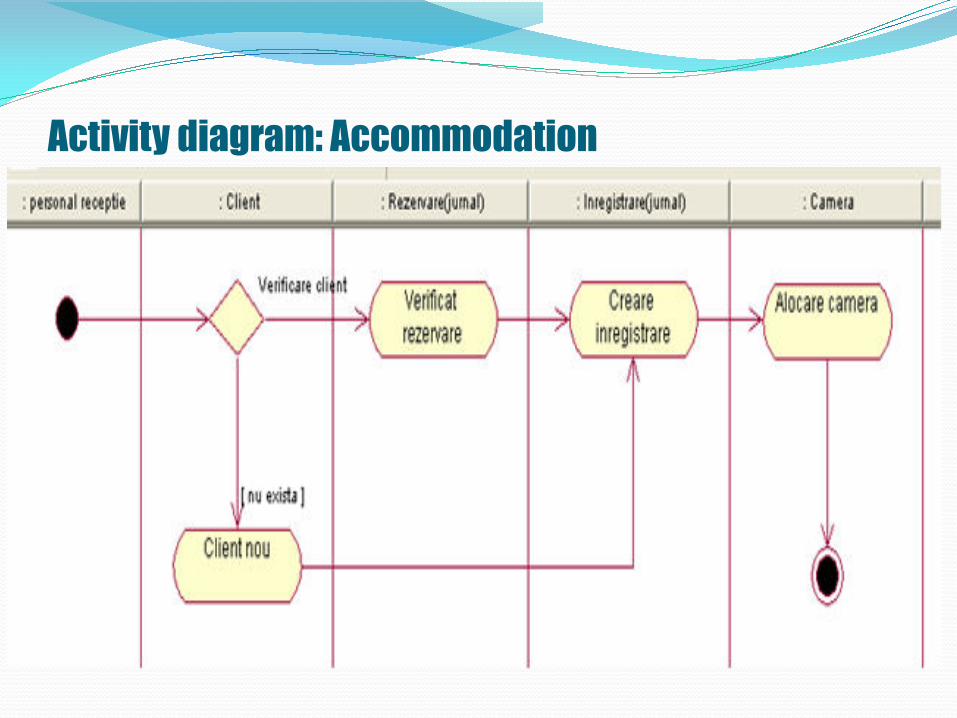
Activity diagram: Accommodation

Activity diagram: Room release

Full class diagram După analiza acestor diagrame obţinem completă a
claselor:

Component diagram
A component diagram shows the dependencies between different software components that make up an IT system.
These dependencies are:
Static - occur in the compilation or link-editing steps
Dynamic - occur during execution
A component is a software module (source code, binary code, dll, executable etc) with a well-defined interface.

Component diagram
Usually, the name of a component is the name of the file represented by the component.
Objects implemented by a component instance are represented graphically inside the component instance symbol.
Graphical representation of components in UML

Component diagram
The component diagram is a graph of components between which there are dependency or composition relationships (components physically included in other components).
Component dependencies are graphically represented through interrupted lines between a client component and a service provider component, targeting the vendor component.
The dependency relationship means that the classes included in the client component can inherit, instantiate or use classes included in the vendor component.
There may also be relationships of dependence between components and interfaces of other components, relationships that mean that a client uses vendor component operations

Component diagram
Examples of predefined stereotypes for components:
<<Main Program>>
<<SubProgram>>
<<Package>>
<<DLL>>
<<Task>>
<<EXE>>

Component diagram example

Deployment diagram
Deployment diagrams show the configuration of the processing elements during execution and the components, processes and objects they contain.
A deployment diagram is a graph of nodes connected through communication associations.
A node is a physical entity that is a processing resource with memory and processing capabilities (computing devices, human resources, mechanical processing resources).
A node is graphically represented by a parallelepiped. A node type has a name associated, and an instance of a node has (optionally) an instance name and a type name (instance name: type name). An association between two nodes indicates the existence of a communication path between nodes.

Deployment diagram
Deployment diagrams can be used to represent components that may belong to certain nodes by embedding the component symbol within the symbol representing the node.
There may also be dependency relationships between components.
Deployment diagram
Deployment diagrams contain two types of nodes: Execution environments and devices.
Execution environments are hardware components capable of running programs.
Devices are non-computing hardware components. The name associated with a device is generally generic (eg printer, modem, terminal etc.)
A connection is a hardware link (generally bidirectional) between two devices or processors.
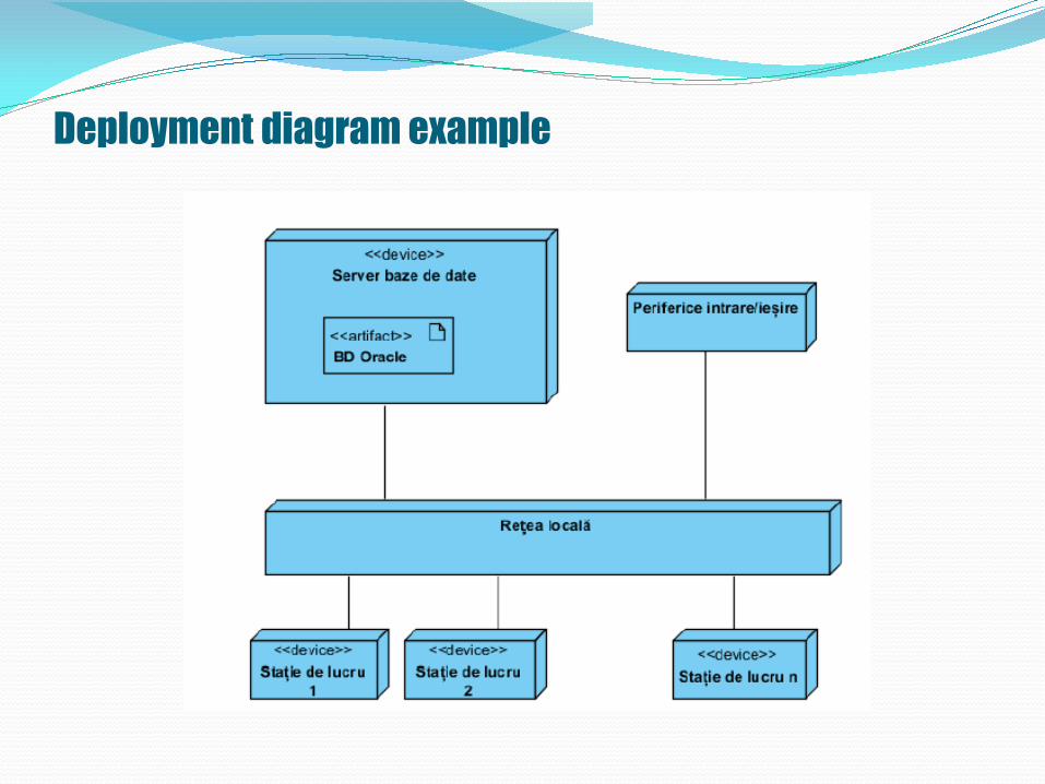
Deployment diagram example


![Curs 1-6 Traumatisme Curs [Compatibility Mode]](https://static.fdocuments.in/doc/165x107/577cdf6d1a28ab9e78b135f9/curs-1-6-traumatisme-curs-compatibility-mode.jpg)