RELAP5 Analyses of a Deep Burn High Temperature Reactor Core Hongbin Zhang*, Michael Pope, Haihua...
13
RELAP5 Analyses of a Deep Burn High Temperature Reactor Core Hongbin Zhang*, Michael Pope, Haihua Zhao Idaho National Laboratory *Email: [email protected] 2010 RELAP5 International Users Seminar September 20-23, 2010, West Yellowstone, Montana Acknowledgement: Authors are grateful for Paul Bayless’s help to set up the RELAP5 input deck.
-
Upload
roderick-short -
Category
Documents
-
view
217 -
download
0
Transcript of RELAP5 Analyses of a Deep Burn High Temperature Reactor Core Hongbin Zhang*, Michael Pope, Haihua...
RELAP5 Analyses of a Deep Burn High Temperature Reactor Core
Hongbin Zhang*, Michael Pope, Haihua ZhaoIdaho National Laboratory
*Email: [email protected] RELAP5 International Users SeminarSeptember 20-23, 2010, West Yellowstone, Montana
Acknowledgement: Authors are grateful for Paul Bayless’s help to set up the RELAP5 input deck.

Prismatic Deep Burn Concept
LWR used fuel
TRU kernelTRU TRISO
Compacts
Fuel ElementsDeep Burn Core
Burn-up to 750 GWD/MT is feasible
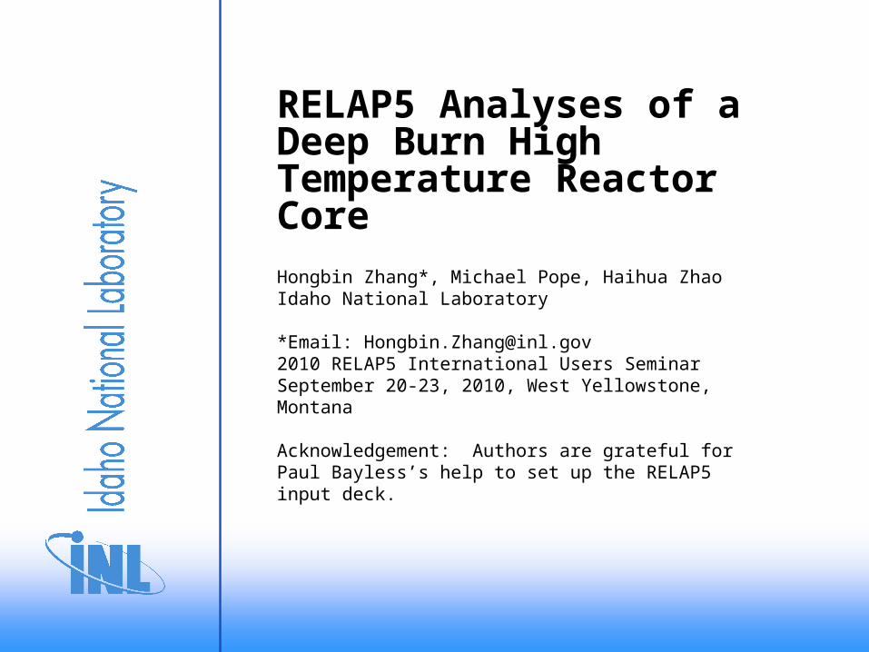
Fuel Composition• Packing fraction of TRISO particles is 18%.
• Fuel kernel diameter is 200 um.
• TRU fuel representative of PWR spent fuel after 5 years of cooling.
Nuclide Fraction (wt%)Np-237 6.8
Pu-238 2.9
Pu-239 49.5
Pu-240 23.0
Pu-241 8.8
Pu-242 4.9
Am-241 2.8
Am-242 0.02
Am-243 1.4

2D Lattice Calculations
• DRAGON – collision probability transport code developed by Institut de Génie Nucléaire, École Polytechnique de Montréal, Montréal. 172 energy groups for various temperature and burnups.
• 23 group homogenized cross sections generated for DIF3D.
• Reflector: 1-D model of the core with a representative fuel region and a reflector zone.
Schematic of 1/12 fuel block model used in DRAGON
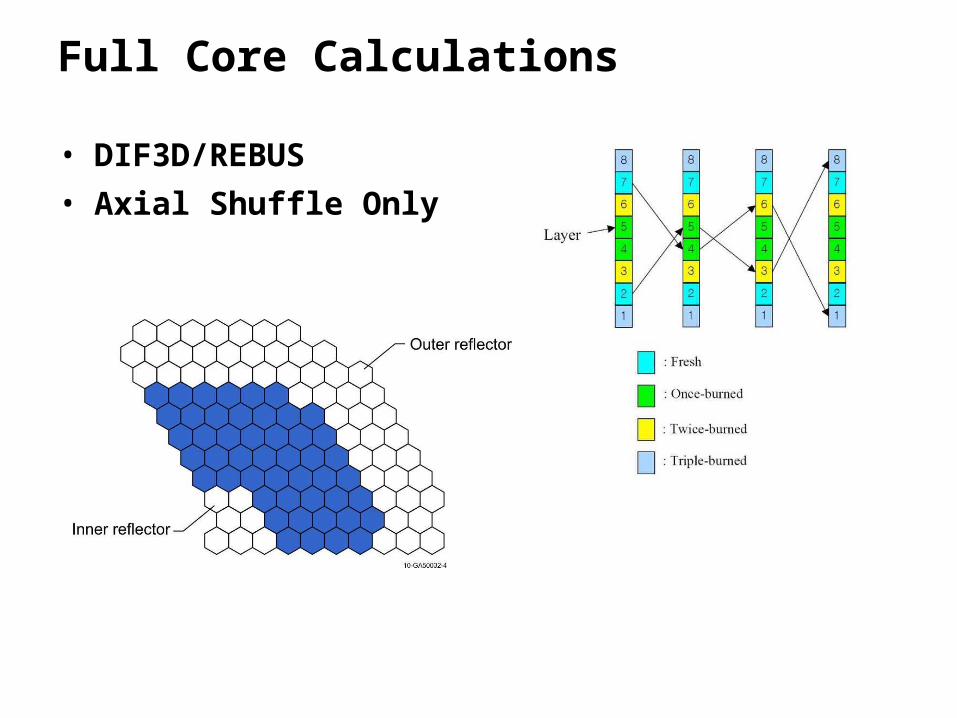
Full Core Calculations
• DIF3D/REBUS
• Axial Shuffle Only
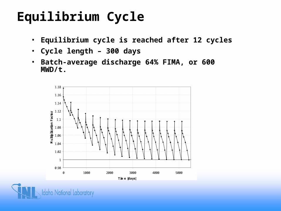
Equilibrium Cycle
• Equilibrium cycle is reached after 12 cycles
• Cycle length – 300 days
• Batch-average discharge 64% FIMA, or 600 MWD/t.
0.98
1
1.02
1.04
1.06
1.08
1.1
1.12
1.14
1.16
1.18
0 1000 2000 3000 4000 5000
Time [days]
Mu
ltip
lica
tio
n F
acto
r

Decay Heat Curve
Decay heat curve is from calculations by Professor Kostadin Ivanov at Penn State
0%
1%
2%
3%
4%
5%
6%
7%
0 20 40 60 80 100 120
Time (Hr)
Dec
ay h
eat,
%
Fuel at 7 GWd/ton burnup
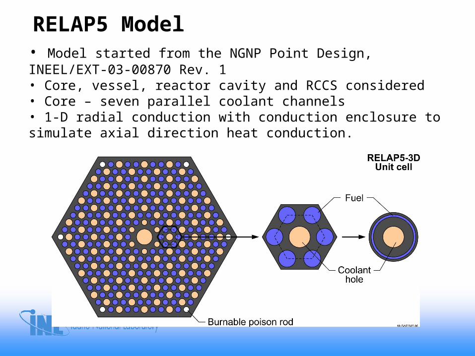
RELAP5 Model• Model started from the NGNP Point Design, INEEL/EXT-03-00870 Rev. 1• Core, vessel, reactor cavity and RCCS considered• Core – seven parallel coolant channels• 1-D radial conduction with conduction enclosure to simulate axial direction heat conduction.
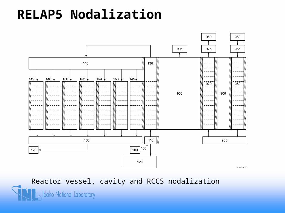
RELAP5 Nodalization
Reactor vessel, cavity and RCCS nodalization

RELAP5 Steady State Results
• Reactor Power: 600 MWth.
• Reactor Inlet Temperature: 491°C.
• Reactor Outlet Temperature: 850°C.
• Core Flow Rate: 324 KG/S
• Bypass Flow Fraction: 12%

Low Pressure Conduction Cooldown Results
0
200
400
600
800
1000
1200
1400
1600
1800
2000
0 10 20 30 40 50 60 70 80 90 100
Time (Hr)
Te
mp
era
ture
(C
)
Fuel
Vessel

High Pressure Conduction Cooldown Results
0
200
400
600
800
1000
1200
1400
1600
0 10 20 30 40 50 60 70 80 90 100
Time (Hr)
Te
mp
era
ture
(C
)
Fuel
Vessel

Summary
• LPCC (depressurized loss of forced cooling) transients showed fuel temperatures exceed 1600oC
• However, very conservative consumptions went into the RELAP5 calculations
– Burnable poisons and power flattening measures were not considered
– Very conservative decay heat curve was used
• Ongoing promising work by other researchers to use burnable poisons and better fuel shuffling scheme to lower fuel temperature.