REL 521 * 1 - ABB Group€¦ · · 2015-05-16the two optionally built-in serial ports, brings REL...
19
1 MAK 506 003-BEN Page 1 ...\..- REL 521 * 1.2 Line distance protection terminal ABB Network Partner (SEgS 02 16) Features ~ .The basic version of REL 521 includes: -three distance protection zones with individual setting of the directionality and reach in reac- live and resistive direction -instantaneous overcurrent protection -switch-onto-fault protection facilities -programmable communication schemes with a built-in unblocking function, weak end infeed logic and current reversallogic -three-phase tripping -presentation of the measured mean values of the line current, voltage, active power, reactive power and frequency, together with the actual statuses of all input and internai binary signals -extensive configuration possibilities by use of built-in logical gales, timers and user config- urable connections between different func- tions, binary inputs and binary outputs .Simultaneous measurement of the phase- phase and ph ase-earth loop impedances within the numerical measuring elements that are indi- vidual for each type of fault and each distance zone ensures fast and reliable fault detection .The minimum operating time is 13 ms .The multiprocessor-based design guarantees high availability together with excellent possibili- ties for extensive combination of different option al functions .Numerical filtering and measuring technique ensures a correct performance du ring CT satu- ration and CVT transients .Versatile local man machine communication (MMC) from the relay front panel, together with the two optionally built-in serial ports, brings REL 521 close to the user, whether he be located in a substation, controi centre or office .Extensive self-supervision with fault diagnostics presented on an MM I unit .Oetailed disturbance reporting for the last ten disturbances with up to 150 time-tagged events for each reported disturbance ..~.a'..~. .~~, Changed since Oclober 1997 Data subject lo change wilhoul nolice
Transcript of REL 521 * 1 - ABB Group€¦ · · 2015-05-16the two optionally built-in serial ports, brings REL...

1 MAK 506 003-BENPage 1...\..-
REL 521 * 1.2
Line distance protection terminal
ABB Network Partner
(SEgS 02 16)
Features~
.The basic version of REL 521 includes:
-three distance protection zones with individualsetting of the directionality and reach in reac-live and resistive direction
-instantaneous overcurrent protection
-switch-onto-fault protection facilities
-programmable communication schemes witha built-in unblocking function, weak end infeedlogic and current reversallogic
-three-phase tripping-presentation of the measured mean values of
the line current, voltage, active power, reactivepower and frequency, together with the actualstatuses of all input and internai binary signals
-extensive configuration possibilities by use ofbuilt-in logical gales, timers and user config-urable connections between different func-tions, binary inputs and binary outputs
.Simultaneous measurement of the phase-phase and ph ase-earth loop impedances withinthe numerical measuring elements that are indi-vidual for each type of fault and each distancezone ensures fast and reliable fault detection
.The minimum operating time is 13 ms
.The multiprocessor-based design guaranteeshigh availability together with excellent possibili-ties for extensive combination of differentoption al functions
.Numerical filtering and measuring techniqueensures a correct performance du ring CT satu-ration and CVT transients
.Versatile local man machine communication(MMC) from the relay front panel, together withthe two optionally built-in serial ports, bringsREL 521 close to the user, whether he belocated in a substation, controi centre or office
.Extensive self-supervision with fault diagnosticspresented on an MM I unit
.Oetailed disturbance reporting for the last tendisturbances with up to 150 time-tagged eventsfor each reported disturbance
..~.a'..~. .~~,Changed since Oclober 1997Data subject lo change wilhoul nolice
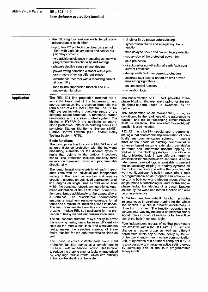
ABB Network Partner REL 521 * 1.2
Line distance protection terminal
-single or three-phase autoreclosing
-synchronism check and energizing checkfunction
-time delayed under and overvoltage protection
-supervision of the protected power line
-stub protection
-directional or non-directional earth fault over-current protection
-4-step earth fault overcurrent protection
-accurate fault locator based on weil proven
measuring algorithms-on-line controi function
-simulation logic I
Application~
The basic version of REL 521 provides three-phase tripping. Single-phase tripping for the sin-gle-phase-to-earth faults is available as anoption.
The acceleration of an overreaching zone, asconditioned by the readiness of the autoreclosingfunction and the corresponding circuit breakeritself, is available. The so-called "loss-of-load"function is also included.
REL 521 has a built-in, special user-programma-bre logic that enables the implementation of prac-tically any communication scheme. It coversmost of the needs of existing communicationschemes based on zone extension, permissiveoverreach and underreach transfer tripping, asweil as on the blocking principle. In addition tothis, unblocking logic in two different modes isavailable within the permissive schemes. A sepa-rate current reversal logic is available to preventthe unnecessary tripping of healthy systems onthe multi-circuit lines and within the complex net-work configurations. A built-in weak infeed logicis programmable so as to operate in echo modeonly, or in both echo and tripping mode. When asingle-phase autoreclosing is used for the single-phase faults, the tripping of a circuit breakercaused by the weak end infeed function can alsobe phase-selective.
A built-in switch-onto-fault function providesinstantaneous three-phase tripping for the wholeline section if a circuit breaker accidentally isclosed on to a fault. The function operates in aconventionai way (by means of an external binarysignal from a CB controi switch), or by the activa-tio n of the built-in optionallogic.
Four independent groups of setting parametersare available within the REL 521. The user canchange an active group as weil as differentparameters within any of them locally by the aidof the user-friendly man machine communicationunit, or by means of a personal computer (PC). Itis also possible to change an active setting groupby activating one of the four programmablebinary inputs.
.The following functions are available optionally,independent of each other:
-up to five I/O printed circuit boards, each ofthe m with eight binary inputs and twelve out-put relay contacts
-two additional distance measuring zones withprogrammable directionality and settings
-phase-selective single-phase tripping-power swing detection element with a pro-
grammable effect on different zones
-disturbance recorder with a recording time ofat least 10 s
-fuse failure supervision function and CT-supervision function
~ -The REL 521 line protection terminal rep re-sents the basic unit of the transmission andsub-transmission line protection terminals thatform a part of a PYRAMID system. The PYRA-MID system includes a complete range of thecomplex object terminals, a functional stationmonitoring, and a station controi system. Theblocks in PYRAMID are available as stand-alone protection units or as building blocks in acomplete Station Monitoring System (SMS),Station Controi System (SCS) and/or Relay
Testing System (RTS).
Basic functionsThe basic protection function in REL 521 is a fullscheme distance protection with the individualmeasuring elements for the different types offaults that belong to the various impedancezones. The protection includes basically threeimpedance measuring zones with programmable
directionality.
The quadrilateral characteristic of each imped-anGe zon e with an individual and independentsetting of the reach in reactive and resistivedirection, ensures an optimized application for allline lengths on single lines as weil as on lineswithin the complex network configurations. Auto-matiG adaptation of the earth return compensa-tion contributes additionally to the adaptability ofa terminal. The quadrilateral characteristicensures a maximum resistive coverage for allfaults and a maximum limitation of load influence.The load compensated reactance characteristicof zone 1 makes REL 521 applicable for the pro-tection of heavy loaded long transmission lines.
The full scheme distance relay's ability to coverthe evolving faults, faults between different cir-cuits on the multi-circuit lines, and simultaneousfaults, makes the selective clearing of thesefaults feasible for the sub-transmission lines asweil.
The phase selective instantaneous overcurrentprotection function serves as a complement tothe basic underimpedance function. This in orderto reduce the tripping time for faults characterizedby very high fault currents, which can criticallyinfluence the stability of the system.
---
Connections between different functional inputsand outputs, binary inputs and binary outputs areuser configurable. The user can configure allbuilt-in functions according to his needs. A highnumber of different logical gates and timers withindividual settable time delays extends addition-ally the total flexibility of terminals.
The MMI serves as an information unit, present-ing in a Iogicalorder starting and tripping signalsthat have appeared during each of the last tenrecorded disturbances.
Furthermore, each of the two local MMC possi-bilities takes over the functionality of the measur-ing instruments such as the A-meter, V-meter,VAr-meter, W-meter and Hz-meter. The actualstatuses of all binary input signals and internailogical signals are available too. Directional testsduring commissioning become a routine by usingthe REL 521 and its man machine communica-tion possibilities.
Up to 150 time-tagged events for each of the lastten recorded disturbances are available via SMS,SCS or the PC-connection on the front. Time syn-chronization is possible by means of the minutepulses wired to a separate binary input as weil asvia the optionally built-in communication ports forremote communication.
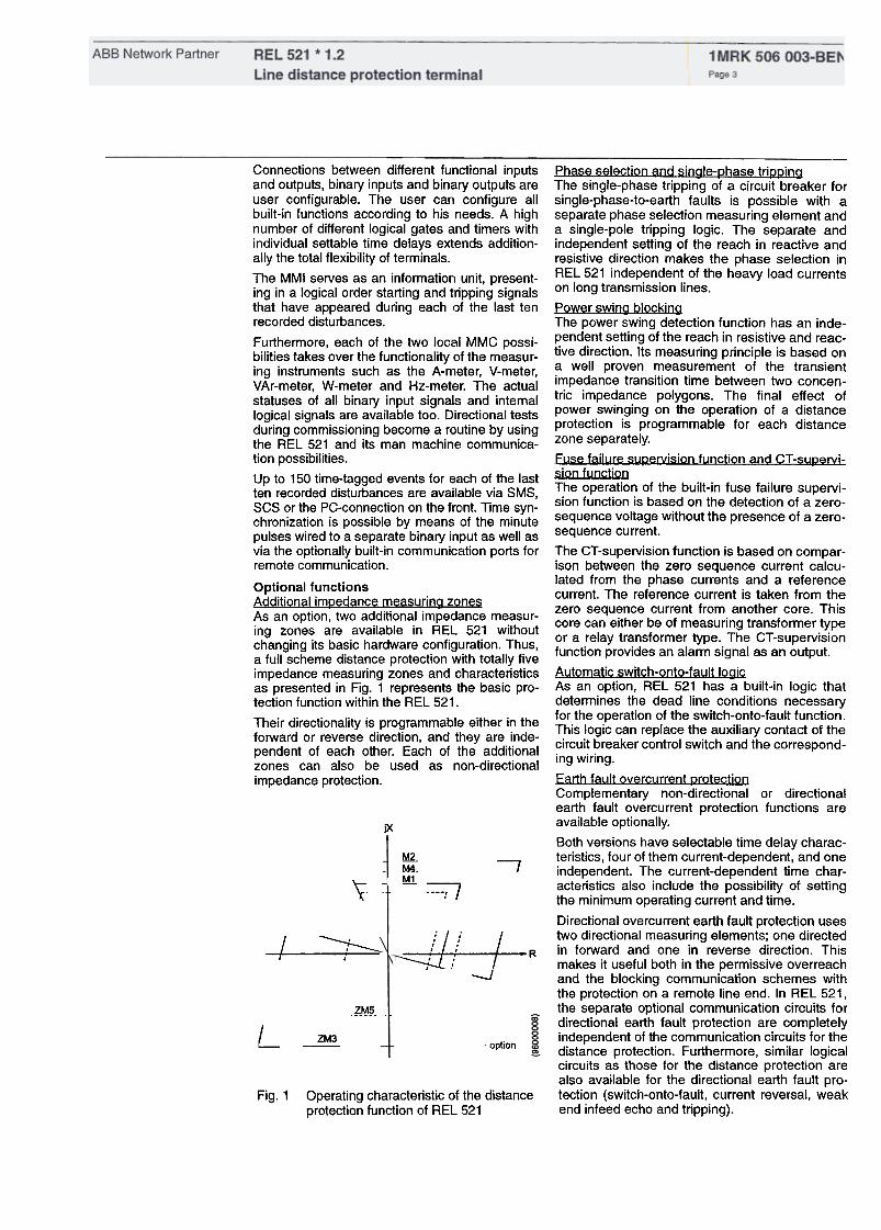
Optional functionsAdditional im(2edancemeasuring zonesAs an option, two additional impedance measur-ing zones are available in REL 521 withoutchanging its basic hardware configuration. Thus,a full scheme distance protection with totally fiveimpedance measuring zones and characteristicsas presented in Fig. 1 represents the basic pro-tection function within the REL 521.
Their directionality is programmable either in theforward or reverse direction, and they are inde-pendent of each other. Each of the additionalzones can also be used as non-directional
impedance protection.
jX
~
._ZM4.~ I
'\
=;I
--Phase selection and single-~hase tri~~ingThe single-phase tripping of a circuit breaker forsingle-phase-to-earth faults is possible with aseparate phase selection measuring element anda single-pole tripping logic. The separate andindependent setting of the reach in reactive andresistive direction makes the phase selection inREL 521 independent of the heavy load currentson long transmission lines.
Power swing blockingThe power swing detection function has an inde-pendent setting of the reach in resistive and reac-tive direction. Its measuring principle is based ona weil proven measurement of the transientimpedance transition time between two concen-tric impedance polygons. The final effect ofpower swinging on the operation of a distanceprotection is programmable for each distancezone separately.
Fuse failure su~ervision function and CT -su~ervi-sion functionThe operation of the built-in fuse failure supervi-sion function is based on the detection of a zero-sequence voltage without the presence of a zero-sequence current.
The CT-supervision function is based on compar-isDn between the zero sequence current calcu-lated from the phase currents and a referencecurrent. The reference current is taken from thezero sequence current from another care. Thiscare can either be of measuring transformer typeor a relay transformer type. The CT -supervisionfunction provides an alarm signal as an output.
Automatic switch-onto-fault logicAs an option, REL 521 has a built-in logic thatdetermines the dead line conditions necessaryfor the operation of the switch-onto-fault function.This logic can replace the auxiliary contact of thecircuit breaker controi switch and the correspond-
ing wiring.
Earth fault overcurrent ~rotectionComplementary non-directional or directionalearth fault overcurrent protection functions areavailable optionally.
80th versions have selectable time delay charac-teristics, four of the m current-dependent, and oneindependent. The current-dependent time char-acteristics als o include the possibility of settingthe minimum operating current and time.
Directional overcurrent earth fault protection usestwo directional measuring elements; one directedin forward and one in reverse direction. Thismakes it useful both in the permissive overreachand the blocking communication schemes withthe protection on a remote line end. In REL 521,the separate optional communication circuits fordirectional earth fault protection are completelyindependent of the communication circuits for thedistance protection. Furthermore, similar logicalcircuits as those for the distance protection arealso available for the directional earth fault pro-tection (switch-onto-fault. current reversal, weakend infeed echo and tripping).
I/===t ::::::::::
\
~f t ~. ..:: ;: R
-J
?-~~-
L ZM3option
Fig. 1 Operating characteristic of the distanceprotection function of REL 521
ABB Network Partner1 MRK 506 003-BENPage 4
REL 521 * 1.2
Line distance protection terminal
In addition an optional 4-step earth fault protec-tian is available. The 4-step earth fault protectionis intended for solidly earth ed systems wherethere is a need for selectivity both for low andhigh zero sequence currents.The 4-step earth fault protection have three stepswith definite time function and one step with com-bined definite and inverse time function.
The 4-step earth fault protection measures zerosequence current (310) and zero sequence volt-age (3UO). The directional function has an char-acteristic angle of 65 degrees i.e. maximumsensitivity is achieved when the zero sequencecurrent follows the polarized voltage (-3UO) by65 degrees. All four steps can be made direc-tional or non-directional.
In order to avoid influences on the directionalmeasurement by harmonics in the voltage the 4-step earth fault protection is equipped with anharmonic filter. The inverse-time function step isalways blocked if the second harmonic exceedsthe set value (20 or 32% of the zero sequencecurrent). The definite time functions can be setindividually with or with out second harmonic
blocking.
The operation is stabilized against second har-monics. This allows settings for high sensitivitywithout unwanted tripping due to residual inrushcurrents in the transformer.
Fault locatorAn optional fault locator is an essentiai comple-ment to the distance protection, since it mea-sures distance to the fault with great accuracy.
The option provides a fault location together withthe information on the actual primary and sec-ondary phasors of the voltages and currents in arelay point. The pre-fault and fault values of cur-rents and voltages in a relay point, recordedtogether with their phase relations for the last tenrecorded disturbances, are also available.
A calculation algorithm compensates the effect ofthe load currents and the apparent fault resis-tance.
Disturbance recorderThe disturbance recording function is an impor-tant part of a station monitoring system, whichenables the evaluation of different events withinthe power system.
The optional disturbance recorder with a highperformance is one of the building blocks withinthe REL 521. It can memorize up to 10 analogueand 48 binary signals (input binary signals orinternai signals) that are available within the ter-minal. The minimum total recording time is 10seconds.
Any of the recorded analogue and binary signalsis programmable to start arecording. Further-more, analogue signals are programmable foroverfunctions and underfunctions, and binary sig-nals can start recording with a transition from alogical O to a logical 1 and vice versa.
The time base is synchronized with an internaiclock and via the synchronizing facilities furtheron to the system. Pre-fault time, post-fault timeand limit time are settable in wide ranges.
The disturbance recorder option can be selectedas a disturbance recorder with extended memory.
It is possible to locally collect disturbance recordsby means of a PC used for local man machinecommunication, as weil as remotely within theSMS. The disturbance evaluating PC-based pro-gram type REVAL, operating in MS Windows, isalso available.
AutoreclosingThe autoreclosing option consists of a single and/or three-phase one or multi-shot autoreclosing.
The reclosing function can be selected to performsingle-phase and/or three phase reclosing fromeight single shot to multiple shot reclosing pro-grams. The three-phase autoreclose open timecan be selected to give either high speed autore-closing or delayed autoreclosing.
Three phase autoreclosing can be performedwith or with out the use of an optional synchro-nism check or energizing check function.
Extensive information on the operation of areclosing function is available to the user at anytime.
S~nchronism andenergizing check functionThe built-in synchronism check function has allthe characteristic operating parameters settablein wide ranges. The energizing check functionmakes possible energizing of dead line as weil asenergizing of dead busbar or energizing in bothdirections.
Breaker failure grotectionThe optional breaker failure protection as builtinta REL 521 measures the current flowingthrough a corresponding line circuit breaker.
Two timers are available, one independent on theother: timer T1 for a repeated tripping of ils owncircuit breaker, and timer T2 that operates thecorresponding output relays, connected inta thebreaker failure tripping logic.
Any one of the internai tripping functions will startthe operation of the breaker failure protection. Itis argO possible to program the correspondingbinary inputs for the purpose of starting thebreaker failure protection.
Under/Overvoltage grotectionOptional voltage measuring functions are avail-able in the REL 521 terminals. Operating valuesof the overvoltage and undervoltage measuringelements are settable in wide ranges, indepen-dent one of another. Each of the m has built in anindependent time delayed element with wide set-ting range.
S~stem sugervision functions and stub grotectionDifferent supervision functions that supervise aprotected power line, as weil as the near vicinityof REL 521, are available as an option among thesupervision functions of the system.

Optional input/output facilitiesThe basic version of REL 521 comprises fourbinary inputs and five output relay contacts. Oneof them is anormally closed contact, used for thesignalization of a continuous self-supervisionfunction. Between one and five additional printedcircuit boards, each of them comprising eightbinary inputs and twelve independent outputrelay contacts, are available as an option. All thebinary inputs are freely programmable for any ofthe built-in functions to assure the greatest possi-ble flexibility. All of the REL 521 internai logicalsignals can controi one or more of the output
relays.
All the output relays are freely programmable toany of the internallogical signals.
Optional remote serial communicationOptionally, the corresponding software and oneor two serial communication ports are availablewith the REL 521. They are installed independentof each other on the back plane of the terminal.Remote communication with REL 521 uses theoptical fibres to eliminate the .influence of theelectromagnetic interferences. This enables theREL 521 to be a part of the SMS and/or the SCSat the same time.
Their functionality is based on a measurement ofthe line current (overload protection) and a differ-ence in the phase currents (broken conductorprotection). A loss-of-voltage function with ils trip-ping logic is useful in systems with a built-in auto-matiG restoration function.
The overload protection will change to a stub pro-tection by energizing the corresponding binaryinput in REL 521. It can thus be effectively used
in switchyards with 11/2 circuit breaker configura-
tion when VTs are installed on the line side of thecircuit breakers.
On-line controi functionsOptionally built-in function block makes possibleon line remote controi of up to ten binary signals.On this way the on line controi of the circuitbreakers as weil as different built in functions ispossible remotely via the SCS and SMS.
Simulation logicThe optional simulation logic makes possible tothe user to program an appearance and timesequence of different intemal logical signals andon this way test the operation of different built-indisturbance reporting functions, event handlingwithin the SMS and SCS and exercise the signalflow within the substation.
Design The REL 521 line protection terminal is supplied
in a closed case of common ABB look, which is 3/4 of 19" rack wide and 6U (10") high. A mother-
board is mounted under the front cover of the ter-minal. All other units are of plug-in type and thuseasily removable. Screw connection terminals,mounted on the back plane of the terminal, servefor the electrical connections to the external cir-cuits. Optional optical connectors of type SPA-ZC 21 that serve for remote communication pur-poses within the SCS and SMS are located onthe back plane too.
The basic configuration of REL 521 consists ofthe following units:
-Transformer unit with five voltage and five cur-rent input transformers
-NO conversion unit for 10 analogue signals,operating with a sampling frequency of2000 Hz
-Multiprocessor-basedcentral processing unitthat performs all the REL 521 measuring func-tians
-Power supply unit, which comprises a regu-lated DC/DC converter that provides stabilizedauxiliary voltage to all static circuits. Fourbinary input circuits together with the five out-put relays are installed in the same unit.
-Man machine interface unit is installed on thefront plane of REL 521 and serves as a localcommunication facil ity between the user andthe equipment.
The following hardware units are available
optionally:-up to five input/output units, each of them con-
sisting of eight binary inputs and twelve relayoutput contacts.
-one or two serial interface units of typeSPA ZC 2, intended for remote communicationDurooses.

ABB Network Partner1 MRK 506 003-BENPage 6
Basic versionThe measuring technique used in the REL 521terminal is based on pure numerical methods.The measuring signal processors operate withnumerical signals derived from the analogue-to-digital converter (see Fig. 2).
The self-supervision function operates continu-ously and includes:
-normal microprocessor watchdog function
-checking of digitized measuring signals
-checksum verification of PROM contents
-checksum verification of all types of signalcommunication
-read-write-read-write cycling of the memorycells and internai registers
Transformer unitTotally ten analogue input quantities are pro-cessed in a transformer unit:
-three currents as phase currents of a pro-tected line
-residual current (310) of a protected line
-residua! current (310) of aparalIei operating
line when used (for an optional fault locationfunction only)
-three phase-to-earth voltages of a protectedline
-open delta voltage of a protected line (for anoption al directiona! earth fault protection func-tian, when used)
-one phase-to-earth voltage from the busbarside of a circuit breaker (for an optional syn-chro check /energizirig check function, when
used)
NO conversion unitAnti-aliasing low pass analogue filters filter theanalogue signals before they enter the multi-plexer and an analogue-to-digital converter. Aseparate signal processor in an NO conversionunit performs digital low-pass filtering. The totalbandwidth of the filtered signals will then be suit-able for protection purposes.
The information is then converted from paralIei toserial mode and transmitted to the measuring unit(central processing unit).
Measuring unit (central Qrocessing unit)REL 521 is based on a multiprocessor designwith a 32 bit microcontroller and a number of dig-ital signal processors (OS P). Encoded serialinformation from the NO converter unit isdecoded and changed back to the paralIei infor-mation in the measuring unit. Band pass numeri-Gal filtering of the corresponding current andvoltage signals is performed as weil.
Three OSPs perform abasic impedance measur-ing function. They calculate the impedance asseen for the different fault loops on the basis ofthe complex values of the measured voltages,currents, and changes in the currents. The result-ing impedance is compared with the reactanceand resistance limits determined by the relay set-tings for each fault loop and each distance zoneseparately for each millisecond.
In order to measure the same operational imped-anGe for all fault loops, an earth fault compensa-tio n has been applied for measurement in thephase-to-earth fault loops. It influences the mea-surement in a reactive direction only. The com-pensation will be automatically adapted to linepositive and zero sequence parameters, for eachdistance zone separately.

The resistive reach is adjustable separately for -simplified testing of different functions and wir-
the earth fault measuring .Ioops, and .for the ing.d.u:ing commissioning or any other testing
phase-to-phase fault measurlng loops. It IS setta- actlvltles, not only within REL 521 but also in
ble for the different distance zones, indepen- the external circuits, is feasible by' using the
dently of each other. possibility of setting any of the most important
To maintain a definite directional measurement REL 521 internallogical signals at the logical
for the faults close to the relay point a loop volt- value 1., O, o: at t~e ~ctuallogical value. Gom-
age signal is used in conjunctiorl with a phase pl.et~ slgna.lllng, tripping and logica~ circuits
locked positive sequence memory voltage that wlthln the .lIne b~y can .be tes~ed this way. The
lasts for approximately 100 mg. uSe: ~~ option al simulation loglc makes these
.., actlvltles even more comfortable,A 32 bit mlcrocontroller dlrects the information ,.flow over the CAN bus with the different signal !wo connection POI~ts (transmitti~g a~d receiv-
processors, input/output units and also performs Ing): for t~e connection. of the op~lcal flbres, are
some different logical functions, built into the REL avallable !n the MMI ~nlt.. Thus,. dlsturbance-free
521 line terminal. It also controls the following loGar serl~1 commU~lcatlon with the personal
three communication ports: computer IS als o avallable.
-to the man machine communication unit and The use. of ,a pe~sonal computer simplifies the
connected PC, if any, for local man machine comm.unlcatlon with R,::~ 521 to ~ gre~t exte:nt,
communication and gives the user addltlonal functlonallty WhlCh,
due to the lack of space, is not available in the
-to the station monitoring system SMS (option) MMI unit itself:
-to the substation controi system SCS (option) -up to 150 time-tagged events are available for
Power suQRI~ unit each of the last ten recorded disturbances
The power supply unit c,omprises a:.egulated. ~C/ -disturbance records can be collected by a per-
DC converter th~t p~ovl?es ~ ~tablllzed auxlllary sonal computer and corresponding softwarvoltage to all statIc clrcurts wrthln the REL 521 as e.
weil as to all output relays. Four binary input cir- Options
cuits together with the five output relays are The REL 521 line protection terminal is easily
installed in the same unit. adaptable to the requirements for the protection
Man machine interface (MMI) unit of any transmission powerline, thanks to ils mod-The MmaMcI I . t h Al BB I k d .ular design and multiprocessor-based configura-
Uni as a common 00 an IS,. ..installed on the front plane of REL 521 It is used tlon. This w.ay, the addltlonal hard~are modules
", .and/or addltlonal software functlons can befor local communlcatlon with the personnel on ..'
." .added to the baslc version.
slte. The folloWlng most Important functlons are
unified in the MMI unit: InQut/OutQut units
-settings: Four groups of setting parameters As an opti<?n,. up to fi,:,e in~ut/ou~put units, each of
are settable or readable only by menu-struc- them consIstIng of elght blnary Inputs and twelve
tured, self-explanatory MMI software. Different relay output contacts are avallable to the user of
t h bl .th ' h d ' ff REL521. parame ers are c angea e WI In I e I erent
setting groups. The selection of an active set- Binary inputs are freely programmable as the
ting group is also possible. input logical signals to any of the built-in func-
-information handling: The most important tions, includ!ng th~. ,disturbance recording and
information on the last ten disturbances, event recordlng facIlItIes.
including the time of disturbance, ils duration, This enables the extensive monitoring and evalu-
together with the starting and tripping signals, ation of operation for the terminal itself as weil as
is stored in REL 521 and available to the user that of all associated external circuits.
at any time. via the MMI unit. Inform,ation about More than 300 interna! signals are available for
the a?tualllne current, vol~age, actlve a~d signalling purposes and all of them are freely pro-
rea~tlve power toget~er w!th frequency IS als o grammable to operate any of the additional out-
avallable. The same IS valid for the statuses of put relays
all important internallogical signals. If the ., ..optional fault location is included in REL 521 , Remote senal communication
the information on distance to fault, together One or. two serial interface units of. ty~e SPA-
with the phasors of the pre-fault and fault cur- ZC 21, Intend,ed for. remote communlcatlon !:>ur-
rents and voltages, is available for the last ten poses: make It posslble for t~e REL 5~1 terminal
disturbances as weil. to be Included at the same time both In the SCS
..and SMS or in only one of them. The units are-fault traclng. The f~ult;Y part.of a REL 521 as optional and they are located on the back lane
detected by the bullt-m contInuous self super- of REL 521 P
vision will be presented by the corresponding .
code on the MMI unit. Plastic optical fibres up to the single length of 30
meters, and glass fibres up to the single length of
500 meters can be used as a communication
media.

Technical data
power consumptionbasic terminaleach I/O-boardeach output relay
;14W_1W
$0,1 W
IBinarYlnput ~~cuitsI dc voltage AL
l
Ur = (24/30) VUr = (48/60) V
IUr= (110/125) VIUr= (220/250) V
IZ 20%:1:20%:1:20%1:1:20%
I max. 0,05 W/input
max. 0,1 W/inputI max. 0,2 W/input,max.
0,4 W/input
120°CI
max. 2%
'-50 C to +550 C
I
(10-90)% '(10-90)%
*) max. 350 A for 1 s when COMBIFLEX test switch Included together with the product

Table 6: Contact data (reference standard: IEC 255)---Trip and Signal relaysIFunction or quantity
I
Max sy~tem volt~ge I1250 V ac, dc
11000 V rms
I Fast signal relays
1250 V ac, dc
1800 V dcTest voltage across open contact,1 min
Current carrying capacitycontinuous1 s
8A11OA
ISA10A
Making capacity at inductive road withUR>10 m5
0,251,05
laoA10 A
0,4 AO,4A
i250V/S.OA~reakin~ capacity for ac, cos <p>O,4 250 V/8,0 A
Breaking capacity for dcwith UR<40 ms
t Max~m cap";"Citive io~ -
Table 8: Mean values

ABB Network Partner 1 MRK 506 003-BENPage 10
REL 521 * 1.2
Line distance protection terminal
Table 9: Event recording
Table 10: Remote serial communication
lFunctlonI
Protocol
I Communication speed
I Slave number
I Value
SPA
1300,
1200, 2400, 4800 or 9600 bit/s
'1 to 899
~~~~~=:=yes/no
I ~;a:;~r piastIc
Remote change of active group allowed
I
Remote changed of settings allowed
I Connectors and optical fibres
Table 11: DIsturbance recorder
Settlng range'o -48!
'O -10
!2kHZI (5-250) Hz
(O -5000)% of 'r in steps of 1%
1:- :. _.: I (O -200)% of Ir in steps of 1%
I Functlon
I Number ofbinary signals
I ~~~~:~~~:~aIOgUe signals
Sampling rate
Recording bandwidth
Overcurrent triggering
,(O
-200)% of UrI "3 in steps of 1% at 100 V seG
Undercurrent triggering
';
Number of recorded disturbances
---~
I~~; 1~~):o~f ~~/~31~ s,t~~s~~~ 1%
(50 -300) ms In steps of 10 ms
(100 -3000) ms In steps of 100 ms
(500 -4000) ms in steps of 100 m~
Max 10 disturbances
Value.I Functlon
I
(0,01-2,0) X UrI -./3 at 100 V secoIO,1%~fUr/i3
(0,01-110) x Jr! (0,01-60) X Ir0,5% of Jr---ItyPical15 Smaximum 40 s with extended mem_ory
Tor 30 years with leap years \ I*) The amount of harmonics can affect the maximum storage time

ABB Network Partner 1MRK 506 003-BE~Page 11
REL 521 * 1.2
Line distance protection terminal
I
Value
128ms
Table 12: Zone impedance measurlng elements
Functlon
Operate time
typical
Min. operate current
I ~setting ~atio
I tnree phase or single and three phase
included in the measuring accuracy
Impedance setting range at Jr = 1 A
reactive reach
positive sequence reactance X1zero sequence reactance Xoresistive reachpositive sequence resistance R1zero sequence resistance Rofault resistancefor phase -phase faultsfor phase -earth-faults
Settlng range of timersfor impedance zones
Table 13:Phase selection
I Function
Impedance setting range at Ir = 1 A
reactive reachpositive seq. reactance X1zero seq. reactance Xoresistive reachfor phase-phase faultsfor phase-earth-faults
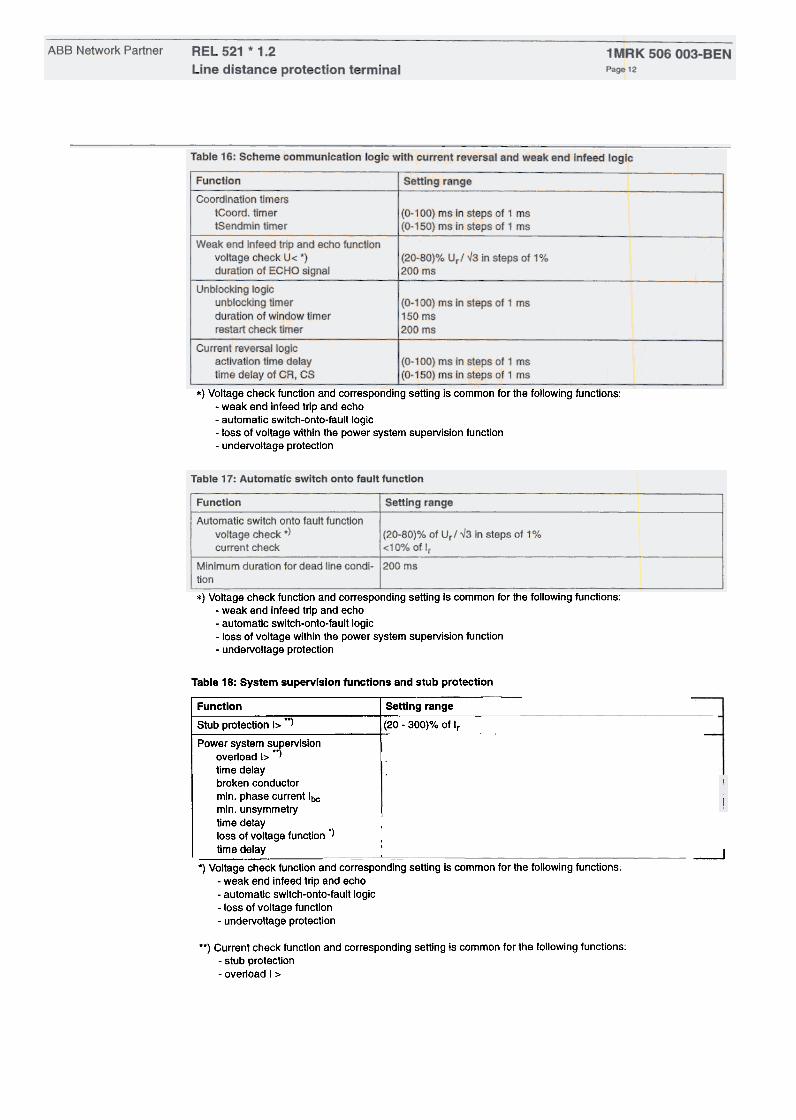
*) Voltage check functlon and corresponding setting is common for the following functions:-weak end Infeed trip and echo-automatic switch-onto-fault logic-loss of voltage within the power system supervision function
-undervoltage protection
*) Voltage check function and corresponding setting is common for the following functions:-weak end infeed trip and echo-automatic switch-onto-fault logic-loss of voltage within the power system supervision function
-undervoltage protection
I (20-300)% of Ir in steps of 1%(0-60) s In steps of 1 s
10% of Ir20% of max. phase currentI (O-50) s in step of 1 s1(20-80)%
of Ur/"3 in steps of 1%
ils
~
Table 18: System supervision functions and stub protection
Function Setting rangeStub protection I> ., (20 -300)%-;;1 Ir ~
Power system s~pervisionoverload I> )
time delaybrokenconductormin. phase current Ibcmin. unsymmetry ,time delay .loss of voltage function ") ,
time delay ~ :_~ ~ -
*) Voltage check functlon and corresponding setting is common for the following functions:-weak end infeed trip and echo-automatic switch-onto-fault logic-loss of voltage function
-undervoltage protection
**) Current check function and corresponding setting is common for the following functions:
-stub protection-overload I >

Table 19: Fuse failure supervision function
I Settlng range
Zero sequence quantities:
operating voltage 3Uo ,(10 -50)% of Ur'-.l3 in steps of 1%operating current 310 (10 -50)% of Ir In steps of 1%
Table 20: CT supervision
Table 21: Fault locator
Table 23: Under- and overvoltage prote!ction
I
Functlon
I Operating voltageundervoltage .jI
TI_~~~:~.ltagellme delayI
undervoltage
overvoltage
I Settlng range
I (20-80)% of UrI -43 in steps of 1%
I (80-2~0)% of UrI -43 in steps of 1o/~
: (O -5) s in steps of 0,1 s
I (O -5) s in steps of 0,1 s
*j Voltage check function and corresponding setting is common for the following functions:-automatic switch-onto-fault logic-loss of voltage function
-undervoltage protection-weak end infeed echo and trip
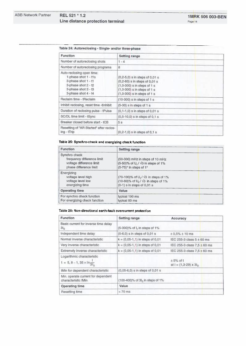
Table 25: Synchro-check and energizing check function
Table 26: Non-directional earth.fault overcurrent protection

ABB Network Partner 1 MRK 506 003-BENPage 15
REL 521 * 1.2
Line distance protection terminal
IAccuracy
l Operating value for directlonal currentmeasurement
\ forward 310 at <p = 650
reverse(5-35)% of Ir in steps of 1 %60% of the setting for forwardI
operation
Characteristic angle 650 lagging
!Independent time delay I (0-6,0) s in steps of 0,01 s
l:t
O,5%:t 10 ms
lEG 255-3 class 5:t 60 msIIEC
255-3 class 7,5:t 60 ms'IEC
255-3 class 7,5 :t 60 ms
Normal inverse characteristic k = (0,05-1,1) in steps of 0,01
I
Very inverse c~aracteristic k = (0,05-1,1) in steps of 0,01
I
Extremely inverse characterlstic
I
k = (0,05-1,1) in steps of 0,01
Logarlthmic characteristicIt = 5.8-1.35xln3To
l:t
5% ottat I = (1,3-29) x 310
I
(O,OS-G,O) s in steps of 0.01 stMin for dependent charact.
Min. operate current for dependent char-acteristic IMin I (100-400)% of 310 in steps of 1%
!110~V ~
11%01110",3
Rated voltage
l Minimum polarising vohageI Communication scheme
I Coordination timer tCoord
I Weak end infeedI voltage check 3Uo
I Operating time
i None, Permissive, Blocking
(0-150) ms in steps of 1 ms
](5-70)% of 110/~3 in steps of 1o/e
Value
1< 70 msI Resetting time
I ~~tting~ang~(50 -2500)% of Ir in steps of 1%
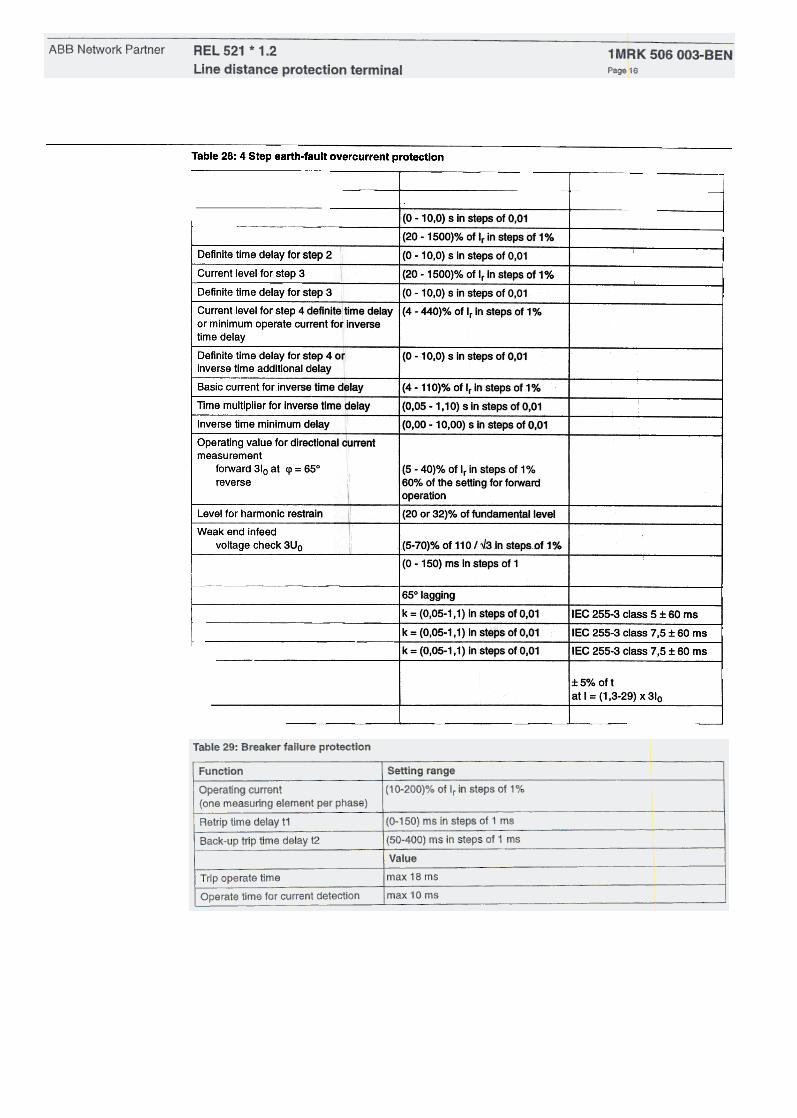
Table 28: 4 Step earth-fault overcurrent protection
Functlon
Current level for step 1
Definite time delay for step 1
! Current level for step 2
I
(O -10,0) s in steps of 0,01
(20 -1500)% of Ir in steps of 1%I
I Defin~e time ~Iay for_step 2
I~
-10.~s in steps of 0,01
(20.1500)% of Ir in steps of 1%
I (O -10,0) s in steps of 0,01
I Current level for step 3---
I ~ite t~:del~or s~ ~Current level for step 4 definite time delayor minimum operate current for inversetime delay
(4 -440)% of Ir in steps of 1%
Definite time delay for step 4 orinverse time additional delay
(O -10,0) S in steps of 0,01
I
Basic current for inverse time deJay(4 -110)% of Ir in steps of 1%
Time multiplier for inverse time delayI -
1(0,05
-1,10) s in steps of 0,01
I
Inverse time minimum delay(0,00 -10,00) s in steps of 0,01
Operating value for directional currentmeasurement
forward 310 at lp = 650
reverse(5 -40)% of Ir in steps of 1%1600;0 of the setting for forward
operation
(20 or 32)% of fundamentailevei
I
Level for harmonic restrain.-Weak end infeed
voltage check 3Uo (5-70)% of 110 I v3 in steps of 1%
Coordination timer tCoord 1(0 -150) ms in steps of 1
I
Characteristic angle650 lagging
k = (0,05-1, 1) in steps of 0,01 lEG 255-3 Glass 5:t 60 ms
k = (0,05-1,1) in steps of 0,01
IIEG
255-3 Glass 7,5 I 60 ms
Ik
= (0,05-1,1) In steps of 0,01 IIEC 255-3 class 7,5:1:60 ms
1:1:
5% of t
at I = (1,3-29) x 310
r110/~3V
I Normal inverse characteristic
~erYi~se -;;~a_ct~~cExtremely inverse characteristic
-
Logarithmic characteristicIt = 5,8-1,35xlnSTo
Rated voltage

Ordering
The basic version of REL 521 is a phase-to-phase and phase-to-ground line distance protection terminalwith three impedance measuring zones and scheme communication logic including current reversal andweak end infeed. High set instantaneous phase overcurrent protection and event recorder are also includedin the basic version.
Ordering Number: 1MRK 000 494-AA Quantity: I I'
Basicdata:
Frequency, fr
Ac voltage, Ur
Dc voltage, EL
50/60 Hz
100/110/11
48/60/110/
D1AD 24/30 V
OSAO 48/60 V
Basic data to specify:
Aated current, Ir
Interface dc voltage, AL 1 D 110/125 V D 220/250 V
Options:Binary in/out rnodule, 8 inputs and 12 output relays.Totally 5 I/O rnodules can be selected.
Quantity (specify interface dc voltage RL2 below) 1 D 2 D
Interface dc voltage, RL2:D 24/30 V D 48/60 V D 110/125 V1MRK 000 173-GA 1MRK 000 173-AB 1MRK 000 173-BBTwo additional zones
Single phase trippingAutornatic switch anta fault logic
Fuse failure (zero sequence quantities) and CT supervision functlonPower swing blocking
Autorecloser, single- and/or three-phase
Synchrocheck and energizing check
Breaker failure protectlon
Earth-fault overcurrent protectlon (only ona alternativecan be selected):
Non-directlonal
Directlonal cornparison or non-directlonal
4-step earth fault overcurrent protection
3D 40 50
D 220/250 V1MAK 000 173-CB
D 1MAK 000 251-AA
D 1 MAK 000 252-AA
D 1MAK 000 253-AA
D 1MAK 000 254-AB
D 1 MAK 000 255-AA
D 1 MAK 000 257-AA
D 1 MAK 000 265-AA
D 1MAK 000 258-AA
D 1MRK 000 259-AA
D 1 MRK 000 260-AA
D 1 MRK 000 209-AA
D 1 MRK 000 256-AA
D 1MRK 000 261-AA
D 1MRK 000 262-AA
D 1MRK 000 263-AA
D 1MRK 001 376-AA
D 1MRK 000 266-AA
D 1MRK 000 267-AA
D 1MRK 000 264-AA
Under/Overvoltage protection
System supervision functions
Fault locator
Disturbance recorder (only ona alternative can be selected):
Disturbance recorder
Disturbance recorder with extended memory
On-line controi function (10 signals)
Simulation logic
Remote communication (SMS/SCS)
5/120 V
125/220/25 V

Bus connection unit for remote communication, type SPA-ZC21 (one for esch port if used):
Transmitter Receiver Quantity:
Plastic
Plastic
Glass
Glass
Plastic
Glass
Plastic
Glass
10101010
20202020
1MRK 000 194-AA
1MRK 000 194-BA
1MRK 000 194-CA
1MRK 000 194-DA
D 1 MAK 000 371-CA
D RK795 017-AA
COMBITEST test switch module RTXP 24 mounted with the terminal inRHGS6 case with window door
DIntemai earthing D External earthing
On/Off switch for the dc-supply
D 1MRK 000 020-BR
D 1 MRK 000 020-DA
D 1MRK 000 020-Y
D 1 MKC 980 001-2
D 1 MRK 000 020-B8
D 1MKC 980 001-2
D
Mounting details with IP40 degree of protection from the front:
19" rack
Wall mounting
Flush mounting
additional for IP54 (protection terminal on ly)
Seml-flush mounting
addition al for IP54 (protection terminal only)
No mounting details
1 MAK 506 003-UEN
1MKC 950 001-1
AS 881 007-AA
1MAK 000 314-GB
1 MAK 000 077-DB
1 MAK 000 078-AA
1MAK 000 876-KA
1MAK 000 876-GA
Accessories:User's Guide for REL 521 * 1.2 Quantity: I I
Frontconnectioncable forPC (Opto/9-pol D-sub) Quantity: I I
SMS-BASE, version 2.0, Basic program for SMS and PC front Quantity: I IconnectionSM/REL 521 SMS Program module for REL 521 * 1.2 Quantity: I I
RECOM Dlsturbance collection program, version 1.3 Quantity: I I
REVAL Disturbance evaluation program, english version Quantity: I I
CAP 531 -Graphical configuration tool Quantity: l ~CAP/REL 521, CAP program module for REL 521 * 1.2 1) Quantity: -I
1) SMS-BASE and SM/REL 521 is required
For Dur reference and statistics we would be pleas ed if we are provided with the following application data:
End user:Country:
Voltage level: kVStation name:
c=

1 MRK 506 003-BEr..Page 19
-Sample specification Line protection terminal with full scheme distance
protection as a main protection function, and adirectional or non-directional earth fault overcur-rent protection function as an optional comple-ment. The fault location function, included as anoption, should have an accuracy higher than 2%,and should not depend on fault resistance, loadcurrent, nor supply of a fault from the differentsources. The design should be microprocessor-based with at least one microprocessor for eachbasic protection function.
Remote communication with the line protectionterminal should be possible from two differentlocations and independent on one another.
A distance protection function should contain fiveindependent impedance measuring zones withquadrilateral characteristics and independent set-tings of the reach in reactive and resistive direc-tian, separately for phase-to-earth and for multi-phase faults. The directionality of all zones, inde-pendent one another, should be programmable.An earth return compensation sh ou Id be settableindependently for each impedance zone.
The line protection terminal should also be appro-priate for the protection of lines within complexnetwork configurations. The full scheme designmust assure reliable operation for simultaneousand intersystem faults on multi-circuit lines asweil as for the different evolving faults.
The minimum operating time of a protection mustnot be more than 13 ms. The maximum operatingtime of distance protection Zone 1, specified for aSIR <10 and faults within 50% of a set reach,must not exceed 40 ms and must be given in theisochronical diagrams measured for the protec-tian terminal connected to capacitive voltagetransformers. The characteristic of distance zone1 in reactive direction must be compensated for aload current. The memory voltage for the properdirectional discrimination at close-in three-phasefaults should be based on a positive sequence
voltage.
It must be possible to select between the direc-tional and non-directional version, when choosingthe earth fault overcurrent protection function. Ilsoperation should be bas ed on a measurement ofthe zero-sequence quantities on the protectedline. Time delay should be selectable betweenindependent and all standardized dependenttime characteristics.
A wide range of permissive tripping and blockingscheme communication logics should be avail-able for the distance protection as weil as for thedirectional earth fault overcurrent protection func-tian. Scheme communication logics should beindependent for both protection schemes withindependent communication facilities. Standardlogics such as current reversal, weak end infeedecho and trip should be provided for both protec-tio n functions. Logics operating with out separatereverse directed measuring elements are not
acceptable.
Local man machine communication should bebased on a user-friendly, menu-structured pro-gram, and performed by the use of a permanentlyinstalled man machine interface unit, type testedtogether with a line protection terminal.
The pre-fault and fault values of currents andvoltages must be available for fault analyzing pur-poses. Remote communication should be possi-ble via a local fibre optical network and thestandard CCITT telephone network. Correspond-ing computer programs must be available. Theremote setting of the different setting parameterswithin at least four groups of setting parametersmust be possible.
The monitoring and controlling of all input andoutput logical signals as weil as tripping signalsmust be possible both locally and remotely. Con-tinuous self supervision function with self diag-nostic possibilities must be included in a lineprotection terminal.
References1MRK 514 003-BEN
1MRK 506 003-UEN
1 MRK 506 003-REN
34 SPACOM 22 EN1 A
1MRK 511 014-BEN
1MRK 511 034-BEN
Series RE 500Mechanical design mounting accessories
User's Guide REL 521 .1.2
Reference List REL 521
SPA-ZC 21
SMS 010
CAP 531