REINFORCED EARTHreinforcedearth.com/sites/default/files/rectangular_panel... · Rectangular Panels....
30
REINFORCED EARTH Construction and Quality Control Procedures Manual Rectangular Panels Construction Manual: Rectangular Panels
Transcript of REINFORCED EARTHreinforcedearth.com/sites/default/files/rectangular_panel... · Rectangular Panels....

REINFORCED EARTH
Construction and Quality ControlProcedures Manual
Rectangular Panels
Con
stru
ctio
n M
anua
l: R
ecta
ngul
ar P
anel
s


CONSTRUCTION AND QUALITY CONTROLPROCEDURES MANUAL
CONTENTS
I. Preface................................................................................................................................................4
II. Non-Disclosure and Disclaimer...........................................................................................................5
III. Introduction..........................................................................................................................................6 A. Purpose......................................................................................................................................6 B. Responsibilities..........................................................................................................................6 C. Plans,Specifications,Layout.....................................................................................................6 D. Components..............................................................................................................................7 E.MaterialsandServicesProvidedbyTheReinforcedEarthCompany.......................................7 F. Equipment,MaterialsToolsandWorkSuppliedbytheContractor............................................8
IV. HandlingReinforcedEarthMaterials A. Concrete Facing Panels............................................................................................................9 B. Reinforcing Strips, Fasteners and Joint Materials...................................................................10
V. Construction Procedures...................................................................................................................12A. Overview..................................................................................................................................12ErectingTolerances.................................................................................................................14
B. Foundation Preparation...........................................................................................................14 C.ErectingtheInitialPanelCourse.............................................................................................15 D. Joint Materials.........................................................................................................................17 E.Backfilling................................................................................................................................17 F. Reinforcing Strips....................................................................................................................19 G. Constructing Second and Subsequent Courses.....................................................................20 H. CompletionofWall..................................................................................................................22
VI. Condition-CauseRelationships..........................................................................................................23
VII. Appendix A. FacingPanelTypesandNomenclature...................................................................................24 B. GlossaryofTerms....................................................................................................................26 C. SafetyTipsforUnloadingReinforcedEarthProducts.............................................................27 D. CompanyLocationsandContactInformation..........................................................................28
4 www.re in fo rcedear th .com
I. Preface
This Construction and Quality Control Procedures Manual has been prepared as a guide in buildingReinforcedEarthstructures.
ItscontentsshouldbethoroughlyreviewedbytheContractor,thesuperintendentandtheforemanresponsibleforconstructionpriortothedeliveryofReinforcedEarthmaterialstothejobsite.
TheReinforcedEarthCompanywillprovideconstructionadvisorstoassisttheContractorintheimplementationofcorrectconstructionprocedures.However,intheeventofanyconflictbetweenthePlans,SpecificationsorContractDocumentsandthisManual, theformerwillprevail. If there isanydoubtwithregardtoanyaspectoftheReinforcedEarthconstruction,contactTheReinforcedEarthCompanybeforecommencingorcontinuingwork.
TheReinforcedEarthCompanysuppliesprecast concrete facingpanelsandaccessories tobeused inconjunctionwithothermaterials in theconstructionofReinforcedEarth retainingwallsdetailed from theconstructiondrawings.TheconstructionandqualitycontrolproceduresmanualfurnishedbyTheReinforcedEarthCompanyisintendedtoprovideageneralexplanationofthesystem.ItistheContractor’sobligationtodeviseandexecuteaprojectspecificerectionsequence,panelunloading,handlingandbracingsystem,andfallprotectionsystem.Thebracingsystemshown in theconstructionandqualitycontrolproceduresmanualisgeneralinnatureanddoesnotaccountforprojectspecificcriteria.Compliancewiththeguidelinesinthismanualdoesnotrelievethecontractorofitsresponsibilitytoadheretotheprojectplans,specificationsandcontractdocumentsorcompliancewithallfallprotection,safetylaws,standardsandproceduresatthejobsite.Contractorsshouldtakespecialprecautionstopreventthepanelsfromshiftingorfallingduringtheerection process.
©2011TheReinforcedEarthCompany.TheinformationcontainedinthisConstructionandQualityControlProceduresManualisprovidedasaguidelinefortheconstructionofReinforcedEarth®structurescomprisedofcertainmaterialssuppliedbyTheReinforcedEarthCompany.ThisManualisnotbeusedforanyotherpurpose.ReproductionofthecontentsofthisdocumentinwholeorpartwithoutthewrittenconsentofTheReinforcedEarthCompanyisexpresslyprohibited.Allrightsreserved.
“ReinforcedEarth”,thecruciformshapeofthepanelsandtheReinforcedEarthlogoareregisteredtrademarksofTheReinforcedEarthCompany.
51-800-446-5700
II. Non-Disclosure Notice and Disclaimer
1. ThisDocumentisthepropertyofTheReinforcedEarthCompany,withheadquartersat8614WestwoodCenterDrive,Suite1100,Vienna,Virginia,22182,andcontainsinformation,whichisproprietarytoTheReinforcedEarthCompany.ThisDocument isbeingmadeavailablesolely foruse inconnectionwithyourinterestorparticipationintheproposedReinforcedEarthproject,andfornootherpurpose.
2. Exceptasspecifiedintheparagraphaboveyoumustnot,withoutthepriorexpresswrittenconsentofTheReinforcedEarthCompany,useanyoftheinformationcontainedinthisDocumentwhethertoconstruct,design,manufacture,fabricate,assemble,produceorinstall,orotherwiseutilize-orcausethesameoranyofthemtobedone-anyelementsofReinforcedEarth(whetherornotpatented),orspecialformsofequipmentuniquetotheproduction,manufacture,fabrication,assembly,installation,orutilizationofReinforcedEarth,orforanyotherpurpose.
3. ThisDocumentandtheinformationcontainedhereinmustnotbecopiedordisclosedinanymannerorform,inwholeorinpart,toanythirdpartywithoutthepriorexpresswrittenconsentofTheReinforcedEarthCompany.
4. ReceiptofDocumentgivesnoentitlementtoanypropertyright intheDocumentor intheinformationcontainedthereinbyvirtueofthetemporarysupplyoftheDocumentinaccordanceherewith.
5. ReinforcedEarthstructuresdesignedbyTheReinforcedEarthCompanycompriseorarebasedsolelyupon:
(a) TheinternalstabilityoftheReinforcedEarthstructurebaseduponthedesignassumptions notedonalldrawingsprovidedbytheTheReinforcedEarthCompanyrelatingtothe structureandtheexternalloads,surchargesandsitegeometriessuppliedbyoronbehalfof theOwner.
(b) Thelayoutandgeometryofthestructurebaseduponsurveydetails,plansand drawingssuppliedbyoronbehalfoftheOwner;and
(c) TheJobSpecifications.
Thedesigndoesnotincludeacheckoftheoverallstabilityofthefoundationsoilsbeloworbehindthestructure,noracheckofanypotentialfailureplanesexternaltothestructure,noracheckofthestabilityofanypermanentortemporaryslopesaboveorbelowthewallortemporaryexcavations.Basedonthecompletenessandaccuracyoftheaboveinformationusedorrelieduponindesigningthestructure,TheReinforcedEarthCompanywarrantstheinternalstabilityofthestructureonly.
6.Upondemand,theDocumentandallcopiesthereofmustbeimmediatelysurrenderedandreturnedtoTheReinforcedEarthCompany.
6 www.re in fo rcedear th .com
III. IntroductionReinforcedEarth®isacompositematerial formedbytheinteractionbetweenafrictionalsoilandreinforcingstrips.Inconcept,itislikereinforcedconcrete;thatis,ReinforcedEarthisaneconomicalmeansofimprovingthemechanicalpropertiesofbasicmaterial,earth,byreinforcingitwithanother,steel.
The reinforcing strips resist stressesproducedwithinthesoilmass;stressesaretransferredtothestripsviafriction.
A Reinforced Earth structure constructed using thistechniqueisshownasthe“reinforcedvolume”inFigure1.PrecastConcretepanelsareusedatthefaceofthereinforcedvolumetopreventerosionofthebackfillandtoprovideanattractive,finishedappearance.
The Contractor and Owner should verify that the Contractor’s on-site erection personnel are in possession of and are familiar with the recommendations of this Procedures Manual.
TechnicalAdvisorsfromtheReinforcedEarthCompanyare available on site during initial construction and thereafter on a request basis. They may assist theContractor withmaterial scheduling and coordinationand provide advice on recommended construction proceduresforReinforcedEarthstructuresassetoutinthismanual.
Technical Advisors are not available on-site on a full-time basis, and are not provided with the intent of replacing the Owner’s and Contractor’s designated quality control and/or inspection staff.
C. Plans, Specifications, and Layout
• Priortocommencinganysitework,thecontractorshould verify that the latest issue of the Plans,Specifications,andContractDocuments-approvedforconstruction-arebeingusedtobuildtheretainingwall.
• TheContractorshouldalsoconfirmthattheretainingwallisbeingconstructedattheproperlocationbyverifyingelevation,line,grade,offset,andallotherlocation criteria.
Only the Engineer can Enforce the requirements of the Plan, Specifications, and Contract Documents. A. Purpose
This document is intended to provide the Owner,Contractor,Engineerandtheinspectionstaff,thosewhoareresponsibleforoverallqualitycontrolandinspectionduring construction with the criteria necessary tomonitortheerectionofReinforcedEarthstructuresforcompliancewiththePlans,Specifications,andContractDocuments.
Unreinforcedconcrete leveling pad
Precastconcretefacing panels
Select granular back�ll
Originalgrade
Randomback�ll
Temporaryconstructionexcavation
TYPICAL SECTION OF A REINFORCED EARTH STRUCTURE
REINFORCEDVOLUME
Reinforcing strips
Figure 1
B. Responsibilities
It is the Contractor’s responsibility to completeconstruction in strict accordance with the Plans,Specifications, and Contract Documents. To assistthe Contractor in this regard, The Reinforced EarthCompanyprovidesrecommendederectionproceduresinthismanual.NothinginthisdocumentisintendedtorelievetheContractoroftheresponsibilityofcomplyingwithallsafetystandardsandconstructionprocedures,includingfallprotection,atthejobsite.

71-800-446-5700
D. Components
ReinforcedEarthstructuresconsistofthefollowing:
Concrete Leveling Pad – A cast-in-place or precast unreinforcedconcretelevelingpadservesasasmooth,level surface for placing panels. Generally this padis6-in. thickand12-in.wide.Refer to thePlansandSpecificationsfordimensionsandrequirements.
Precast Concrete Facing Panels• Full-size–orAn–panelsareusedforthemajority
of the structure. The subscript “n” in paneldesignations indicates the number of reinforcingstripconnectionsortiestripsoneachpanel.
• Alternating full and half height panels of varyingheightsaretypicallyrequiredintheinitialcourse.
• Top-coursepanelsmayhaveaflattopandvaryinheighttoprovideasteppedtransitionatthetopofthestructure.
• Speciallycut,bent,orslopingpanelsasrequiredbythegeometryofthestructure.
Facing Panel Joint Materials • Rubberbearingpadsareplaced in thehorizontal
jointsthroughoutthestructuretopreventconcreteto concrete contact. Rubber shims are used asneededtoadjustforminorvariationsinpanelheight.
• Filtercloth isappliedwithadhesive to thebackfillside of the panels to cover all the horizontal andverticalpaneljoints.
Reinforcing Strips • Ribbedstripsaresuppliedina50-mm(2-in.)width
andvaryinglengthsasrequiredbythedesignofthestructure.
• HighAdherence(HA)ladderstripsaresuppliedin100-mm(4-in.)widthandvaryinglengthasrequiredbythedesignofthestructure.
Both types of reinforcing strips are either galvanizedforpermanentapplicationsorblacksteelfortemporaryapplications.
Fasteners – During construction, reinforcing strips arefastenedtotiestripconnectionsembeddedinthebackofeachfacingpanelusing½-in. diameter bolts, washersandnutsmadeofgalvanizedstructuralsteel.
Select Granular Backfill – Backfill conforming toContract Specifications must be used within the reinforced volume.
E. Materials and Services Provided by The Reinforced Earth Company
• Engineering and design of the Reinforced Earthstructure
• Precast concrete facing panels• Horizontalandverticaljointmaterialandadhesive• Reinforcing strips• Bearingpadsandshims• Structuralbolts,washerandnuts• One set of panel lifting devices• Delivery of The Reinforced Earth Company
furnished materials to the site (F.O.B.) with twohoursoftimeallowedforunloading
• Initialon-sitetechnicalassistanceReinforcing strips, bolt sets, filter fabric, adhesive,bearingpads,andotherspecialitemsprovidedbyTheReinforcedEarthCompanyarebundledandpackedtominimizedamageinunloadingandhandling.
Materials should be thoroughly inspected upon delivery to the job site. Any damaged items should be set aside and The Reinforced Earth Company notified immediately. Materials should be handled and stored to prevent damage or theft. Filter fabric must be stored in a sheltered location and protected from sunlight. Adhesive must be stored in dry location and protected from the elements.
Certificates of compliance with project specificationsforallmaterialsarefurnishedbyTheReinforcedEarthCompany.However,itistheContractor’sresponsibilitytoverify thatallmaterials receivedat the jobsitearein accordance with shipping documents and projectrequirements. Anydiscrepancies shouldbe reportedtoTheReinforcedEarthCompanyimmediately.
To prevent construction delays, the Contractor should continuously monitor the quantity of materials on hand to ensure an adequate supply consistent with the Plans, Specifications, and Contract Documents.

8 www.re in fo rcedear th .com
Summary of Work Performed by Contractor
• Site preparation including shoring, excavation andinstallationofdrainagesystemsasrequired.
• Formingandpouringconcretelevelingpad(s).• Markwalllayoutlineonlevelingpad(s).• Construction of the Reinforced Earth structure
consistingof theerectionandpositioningof facingpanels, installation of joint materials, connectionof reinforcing strips, placement and compaction of SelectGranularBackfill.
• Placementofanyconcretecoping,trafficbarrier,orotherC.I.P.Concreteasrequired.
F. Equipment, Materials, Tools and Work Supplied by ContractorMaterials and Equipment supplied by the Contractor:
• Panel lifting – A hydraulic crane, boom truck orsimilar equipment is required. A standard 5½-in. thickAn facingpanelsweighs3,400lbs;theheaviestplain finish panel weighs 5,300 lbs. Panels witharchitecturalfinishmaybeheavier.
• Backfilling – Dump trucks, scrapers, dozers,graders, front-end loaders, water trucks, etc, areused for hauling dumping and spreading backfill.(Specificequipmentselectionwilldependonbackfill,liftthickness,compactionspecifications,etc).
• Compaction–Largesmooth-drumvibratoryrollersare used for mass compaction of most backfills.Fineuniformsandsarecompactedusingasmooth-drum static roller.
• Small walk-behind vibrating rollers or flat-platecompactorsareneeded forcompactionwithin3 ft.of facing panels.
• ¾-in.WoodenSpacers(Figure2).• Woodenwedges inaquantityat leastsufficient to
provide4to6wedgesperverticaljointforthelengthofstructureunderconstruction(Figure2).
• Clamps, one per vertical joint for the length ofstructure under construction. Additional clamps willbeneededtobracetheinitialcourseofpanels(Figure2).
• Nylonslingsforunloadingpanelstacks.• Lumberfortheinitialcourseofpanels(Figures1)• 24-in.to30-in.Crowbars(pinchbars)• A 4 ft. carpenter level• Wrenchesorsocketsets(7/8-in.)• Clawhammersand16pennyduplexnails• A Sledge Hammer• Chalkline• Broomsorbrushes• A plumb bob• Equal length cables with shackles to connect to
panel lifting devices• LargeSizeCaulkingGunfor(2)lbtubes• SurveyEquipment
Figure 2
1 ½" Clamp must beable to open to 7"
12"
½"all-threadbolt
NutWasher
2 X 6 lumber2 X 4 lumber or
12"
CLAMPOne per vertical joint plus clamps for initial course
4"
1 ½"
1 ½"
3/8" max
WOODEN WEDGESix per vertical joint required
3/4"Approx 3" to 4"
Approx 1" to 2"
3/4" WOODEN SPACER
One per vertical joint on initial course
Required clamp opening may be wider than 7” if panels have an architectural �nish
91-800-446-5700
IV. Handling Reinforced Earth MaterialsA. Concrete Facing Panels
Panel Delivery-Priortothestartofconstruction,theContractorshouldestablishapaneldeliveryschedulethat will allow The Reinforced Earth Company’sprecastertomatchtheirpanelproductionanddeliverytotheContractor’sconstructionschedule.
Panelsareusuallydeliveredonflatbedtrailersinstacksoffourorfivepanelshigh.Thedeliverypointismadeasclosetotheretainingwallsasatruckcanbedrivenunder its own power.
Panelsshouldbefreeofanysurfacedefectsthatmayoccur in transportation, unloading, or storage at theconstruction site, including:• Chippedorbrokenfrontcorners.• Permanent stains on exposed face.• Acrackinpanel’sexposedface.Thesepanelsmayberepairedbeforetheyareusedinthestructure.
Unloading Panels -Undernormalconditions,a two-hourunloadingperiodisallowedperdeliverytounloadpanels.Inthistime,panelsmaybeplaceddirectlyintothestructurebeingconstructedortemporarilystackedfollowingeitherofthesemethods:
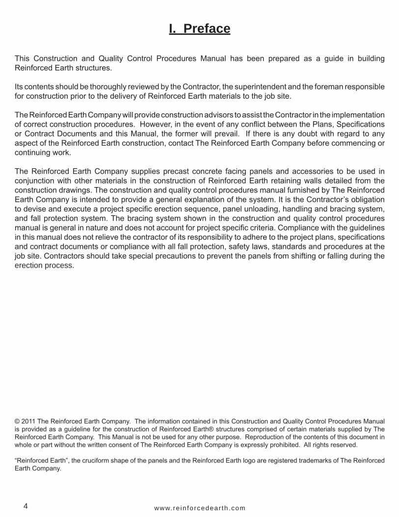
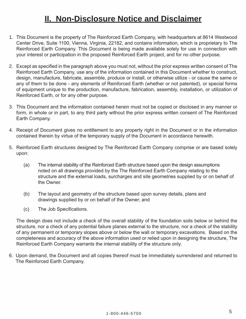
1. byusingliftingdevicestoliftandhandleindividualpanels(Figure3Aand3B)OR
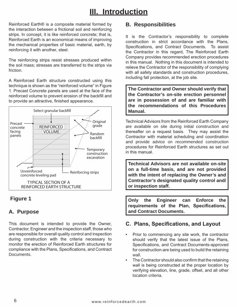
2. byusingnylonslingstoliftandhandleindividualorstacksofpanels(Figure4)
Care must be taken to protect facing panels fromdamageduringhandlingandstorage.
Panels can be stored at the job site by re-stacking.Select a location with firm, level ground for bothstabilityandtoprotectpanelsfromstaining.Carefullyliftandplaceeachpanelfacedownonthenylonpadsof thedunnage. Stacksshouldbenomore thanfivepanelshighwithdunnageusedbetweeneachpanelasillustrated in Figure 5.
Figure 3B
Figure 3A
Never re-stack panels without dunnage. Never place panels face down directly on the ground. Never stand panels up on end.
Figure 4
Any repairs to panels must be completed to the satisfaction of the Engineer.
ATTACHING "RAPID LIFT" DEVICE

10 www.re in fo rcedear th .com
Note: All dunnage and pallets remain the property of The Reinforced Earth Company. They should be stacked and made available for pick-up as soon as they are no longer needed for panel storage.
Panel Storage - Panels should be securely set andblockedonfirm, levelgroundtopreventdamageandstaining during storage.
Figure 5
B. Reinforcing Strips, Fasteners, and Joint Materials
Reinforcing strips - Stripsmaybeup to 32 ft. longand are delivered to the site in bundles of 25 each.Eachbundleweighsapproximately30lbs.perlinearft.Storageintheopenisacceptablebutbundlesshouldnotbeplaceddirectlyontheground(Figure6A).
High Adherence (HA) Ladder Reinforcing Strips - alternatereinforcementtype(Figure6B).
Figure 6A
Figure 6B
PANELS RE-STACKED ON SITE
Dunnage
Not
mor
e th
an 5
hig
h
Dunnage to be aligned with lifting inserts
111-800-446-5700
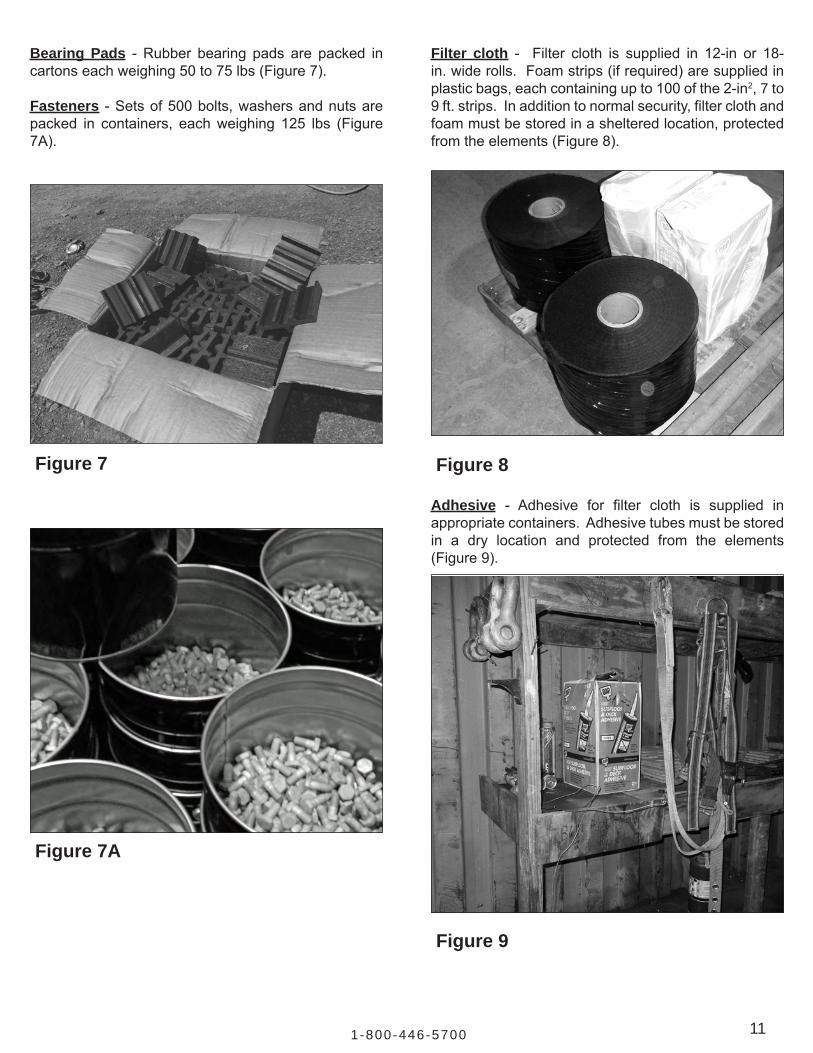
Bearing Pads - Rubber bearing pads are packed incartonseachweighing50to75lbs(Figure7).
Fasteners -Setsof500bolts,washersandnutsarepacked in containers, eachweighing 125 lbs (Figure7A).
Figure 7
Figure 7A
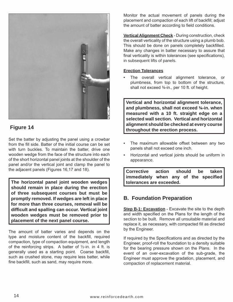
Filter cloth - Filter cloth is supplied in 12-in or 18-in.widerolls.Foamstrips(ifrequired)aresuppliedinplasticbags,eachcontainingupto100ofthe2-in2, 7 to 9ft.strips.Inadditiontonormalsecurity,filterclothandfoammustbestoredinashelteredlocation,protectedfromtheelements(Figure8).
Figure 8
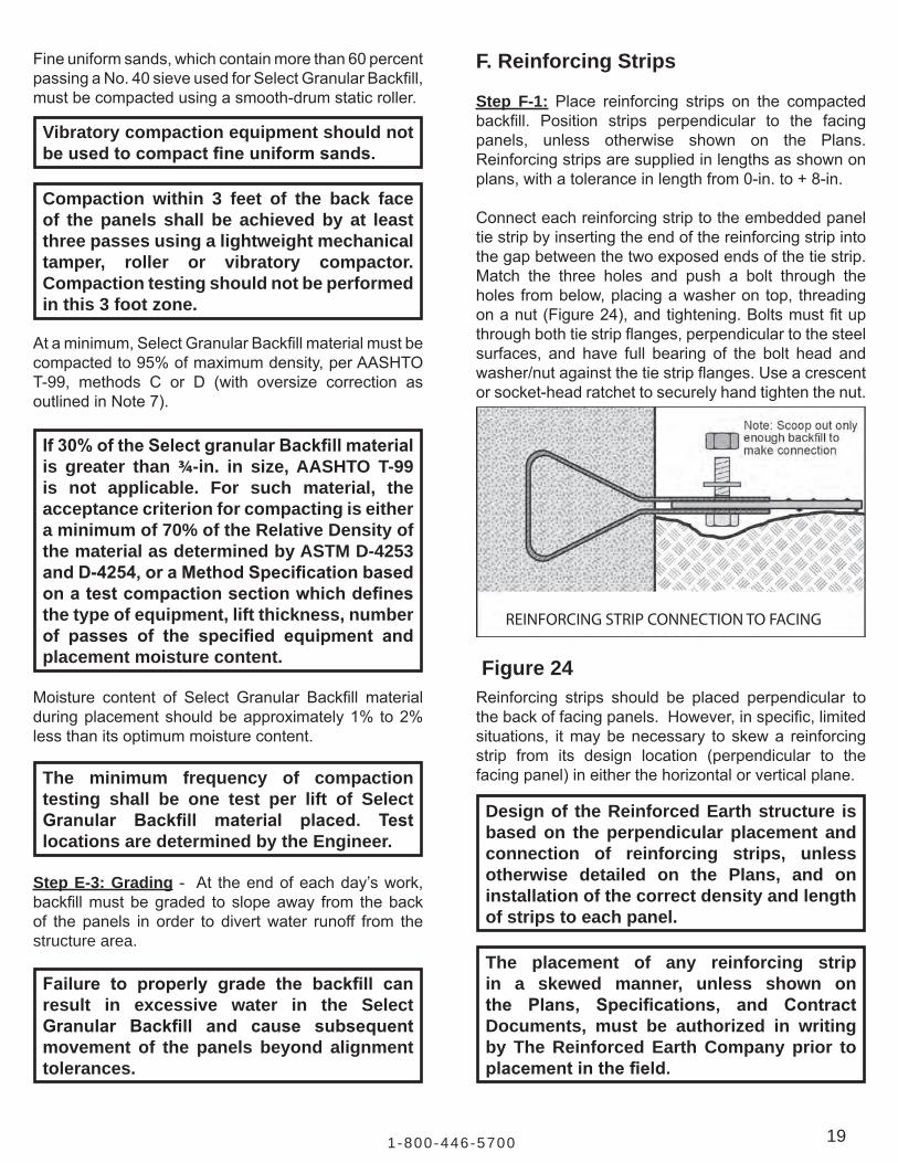
Adhesive - Adhesive for filter cloth is supplied inappropriatecontainers.Adhesivetubesmustbestoredin a dry location and protected from the elements(Figure9).
Figure 9

12 www.re in fo rcedear th .com
V. Construction ProceduresA. Overview
The basic erection sequence for a Reinforced Earthstructurecanbesummarizedinthesesteps:• Preparethesiteincludingexcavationandinstallation
ofdrainagesystemsifrequired.• Form and pour leveling pad (see Step B-3 for
tolerances).• Set and brace the initial course of facing panels,
which consists of alternating half- and full-heightpanels.
• Usewood wedges and clamps to hold panels inposition.
• Attachfilterclothwithadhesive.• Spread and compact backfill in lifts up to 1 to 2
inchesabovethelowestlevelofpaneltiestrips• Connect reinforcing strips to panel tie strips.• Spreadandcompactbackfillinliftstowithin3to5
inchesofthetopofthehalfpanels.• Placebearingpadsandset thesecondcourseof
full panels• Repeatcycleofbackfillingandcompactinginlifts,
connecting strips, placing filter cloth and bearingpads and setting panels until design height isreached.
• Aseachcourseiscompleted,removethewoodenwedgesfromthepanelsinthecoursethreelevelsbelow.
• Settoppanels;connectstrips,completebackfillingand compaction.
• Remove all wedges and clamps.• Installconcretecoping,trafficbarriers,oranyC.I.P.
concrete as required.
The finished appearance of a Reinforced Earthstructuredependstoalargeextentonthecaretakeninerectingandpositioningfacingpanels.Forthisreason,particularattentionmustbepaidtotheinitialcourseoffacingpanelsandtobackfillplacement.
Closeattentiontodetailandaccuracyatthispointwillhelpensuretroublefreeandrapidconstructionoftheremainderofthestructure.
Lifting, Placing and Spacing Panels - Panels can be liftedfromthehorizontal,orstackedposition,directlytoaverticalpositionbyattachingaliftingdevicetoeachof the twocast-in-place lifting insertsat the topedgeof thepanel (Figure3). Usedunnageasblocking topreventdamageaseachpanelrotatesfromhorizontaltovertical(Figure10).
Figure 10
The following position, alignment and procedures should be reviewed prior to the start of construction.
Woodblocking
Lift
Swing
Lift
Lift
Truck bed or ground
LIFTING PANELS FROM STACKS
When placing the initial course of panels, insert aspacertocreateajoint¾”widebetweeneachpanelatthebaseofthefrontfaceofthewall(Figure11B).Note:Aminimumofonespacershouldremaininplaceuntilthenextpaneljoint(inthedirectionofpanelplacement)hasbeenestablishedbyaspacer.Subsequentcoursesofpanelswillbeplacedbycentering thepanel in its’respectiveslot(Figure26).

131-800-446-5700
12
34
56
Note: Panels are set consecutively and may be set starting from either end
Direction of construction Panelbeing placed
CONSTRUCTION SEQUENCE
Figure 11A
Direction of Construction
VERIFY HORIZONTAL LEVEL
4 - ft level
Sight along panel tops
Figure 13
Set Batter -Panelsmustbegivenaslightbatter,ortilt, toward the backfill in order to compensate for asubsequent outwardmovement, which occurs duringbackfill placement and compaction. This movementwill tend topush thepanel toa trueverticalposition.Measurebatterusinga4ft.level(Figure14).
Asshown inFigure13,usea4 ft. level toverify thatthenewpanelislevel.Thensightbackalongthetopsof the panels to ensure that the new panel is at theelevationoftheothersinitscourse.
Correctanyvariationsby lifting thepanelslightlyandinsertingrubbershimsinthehorizontaljointatthepanelbase. Recheckthehorizontalspacingandalignmentafteranysuchadjustment.
Care should be taken to assure that the panel remains centered and properly located until it has been aligned, battered, and clamped.
Figure 11B
Check alignment - Visually check the alignment ofeachpanel inrelationtoeitherthecontrol lineontheleveling pad for the initial course of panels or to thepanelbelowinsubsequentcourses.Makeadjustmentswith a crowbar on the fill sides of the panel (Figure12)so that thesurfacesofsuccessivepanelcoursesare aligned. Do not attempt to adjust the panel byusingthecrowbaronthefrontside–thiscanresultinunacceptablechippingorspalling.
Check horizontal level. Thehorizontallevelofeachpanelshouldbecheckedandadjustedinordertoassureauniformappearanceandeven joints throughout thestructure. Small rubber shims are provided to aid inlevelingthepanels.
Figure 12
Adjust panel base to the front
Adjust panel base to the rear
ADJUST PANEL ALIGNMENT
14 www.re in fo rcedear th .com
Monitor the actual movement of panels during theplacementandcompactionofeachliftofbackfill;adjusttheamountofbatteraccordingtofieldconditions.
Vertical Alignment Check-Duringconstruction,checktheoverallverticalityofthestructureusingaplumbbob.Thisshouldbedoneonpanelscompletelybackfilled.Makeanychangesinbatternecessarytoassurethatfinalverticalityiswithintolerances(seespecifications),in subsequent lifts of panels.
Erection Tolerances• The overall vertical alignment tolerance, or
plumbness, from top to bottom of the structure,shallnotexceed¾-in.,per10ft.ofheight.
• The maximum allowable offset between any twopanelsshallnotexceedoneinch.
• Horizontalandvertical jointsshouldbeuniform inappearance.
Vertical and horizontal alignment tolerance, and plumbness, shall not exceed 3/4-in. when measured with a 10 ft. straight edge on a selected wall section. Vertical and horizontal alignment should be checked at every course throughout the erection process.
Corrective action should be taken immediately when any of the specified tolerances are exceeded.
The amount of batter varies and depends on thetype and moisture content of the backfill, requiredcompaction,typeofcompactionequipment,andlengthof the reinforcing strips. A batter of½-in. in 4 ft. is generally used as a starting point. Coarse backfill,suchascrushedstone,mayrequirelessbatter,whilefinebackfill,suchassand,mayrequiremore.
B. Foundation Preparation
Step B-1: Excavation-ExcavatethesitetothedepthandwidthspecifiedonthePlansforthelengthofthesection to be built. Remove all unsuitable material and replaceit,asnecessary,withcompactedfillasdirectedbytheEngineer.
IfrequiredbytheSpecificationsandasdirectedbytheEngineer,proof-rollthefoundationtoadensitysuitablefor thebearingpressureshownon thePlans. In theevent of an over-excavation of the sub-grade, theEngineermustapprovethegradation,placement,andcompaction of replacement material.
Figure 14
Setthebatterbyadjustingthepanelusingacrowbarfromthefillside.Batteroftheinitialcoursecanbesetwith turn buckles. To maintain the batter, drive onewoodenwedgefromthefaceofthestructureintoeachoftheshorthorizontalpaneljointsattheshoulderofthepaneland/or thevertical jointandclampthepanel totheadjacentpanels(Figures16,17and18).
The horizontal panel joint wooden wedges should remain in place during the erection of three subsequent courses but must be promptly removed. If wedges are left in place for more than three courses, removal will be difficult and spalling can occur. Vertical joint wooden wedges must be removed prior to placement of the next panel course.

151-800-446-5700
Evaluation and approval of foundation suitability is the responsibility of the Engineer. Any foundation soils found to be unsuitable shall be removed and replaced with material approved by the Engineer. The material shall then be compacted, as directed by the Engineer, to a density suitable for the bearing pressure as shown on the Plans, Specifications, and Contract Documents.
Foundation evaluation and control are critical; the behavior and performance of a Reinforced Earth structure is largely dependent upon the foundation on which the reinforced volume is placed.
Step B-2: Drainage System(s) - Installanydrainagesystem(s)asrequiredbythePlansandSpecificationsorasdirectedbytheEngineer.
Step B-3: Leveling Pad -An unreinforced smoothfinishconcretelevelingpadisformedandcastateachfoundation elevation. Leveling pads have nominaldimensionsof6-in.thickby1ft.wideandarecastusinga minimum 2,000-psi, 28-day compressive strengthconcrete.Levelingpadsshouldcureforaminimumof12hoursbeforethesettingofpanels.
Leveling padsmust be cast to the design elevationsas shown on the Plans. The allowable elevationtolerancesare+0.01 ft (1/8-in) and–0.02 ft. (1/4-in.) atdesign elevation.
If thePlanscall for thestructuretohaveastep-upinelevation,pourthehigherlevelingpadasindicatedonthePlans.Leavea12-in.maximum(9-in typical)gapbetweenthehigherpadandthecenterlineofthejointofthelastpanelofthelowercourse(Figure15).
An improperly placed leveling pad can result in subsequent panel misalignment and decreased wall construction productivity.
asindicatedon plans
9" TYP.
LEVELING PADS AT PANEL STEP UP
2.46'
Figure 15
Step B-4: Wall Line-Onthelevelingpadestablishalayoutlineforthefrontfaceofthestructure.Thismaybedifferent than thewall’sLOLgiven in thecontractdocuments.
C. Erecting the Initial Panel Course
Step C-1: Panel Placement -Panel layoutusuallybeginsatthelowestlevelingpadorafixedpointsuchasacornerorexistingstructure(Figure16).Placethefirstpanel[1],thismaybeafullorhalfheightpanel,onthelevelingpad.Checkthehorizontallevelandshimasneeded.Alignthefaceofthepanelalongthelayoutline;andusingbracinginadditiontowoodenwedgesatthebaseofthepanel,setthebatterforthepanel.
Beginbracing the initialcourseofpanelsbysecurelyattaching two adequate lumber braces to each fullpaneland toanypanel inexcessof3 ft. inheight.Asinglebracemaybeusedonpanels3ft. inheightorless(Figures18and19).Bracingshouldbeusedonsubsequentcourseswhenpossible.

16 www.re in fo rcedear th .com
Figure 17
Figure 18
Step C-2: Second Panel Placement - Place thesecond panel [2] on the leveling pad and place aspacertocreateajoint¾-in. wide between it and panel [1] (Figure 16). Spacers must be used during panel erection.Spacersaresuppliedby theContractorandmaybefabricatedfromanyavailable¾-in.material.
Figure 16
Step C-3: Setting Panel Batter-Setthepanel’sbatterasbefore.Clamp thepanel topanel [1] as shown inFigure17.Tightenclampssufficientlytoholdthepanelinpositionwithoutmovement.Woodenwedgesmaybeusedatthebaseofthepanelstotemporarilysetbatterintheinitialcourseofpanels.These wedges must be removed during subsequentconstruction.
Panels must be braced as shown in Figures 18 and 19 prior to releasing the crane from the panel. Bracing must remain in place until all braced panels have had reinforcing strips attached and have been backfilled and compacted up to the top of the braced panels.
1 23
45
6
Direction of construction
Full panels
PLACEMENT OF PANELS IN INITIAL COURSE(Bracing is not shown for illustrative purposes.)
Half panels
Concrete leveling pad
Note: Numbers in squaresshow order of placement
Clamps
3/4” Spacers (typ.)
Bearing pads are not used under the first course ofpanels between the leveling pad, unless specificallyshownonthePlansorseparatelyauthorizedinwritingby The Reinforced Earth Company. If needed, onlyrubbershimsmaybeusedtoshimbetweenthelevelingpadandfirstcourseofpanels.Permanentwoodshimsarenotpermittedatanypointinthestructure.
Throughout construction it is of utmost importance that the panel type and number of tie strips of each panel match the requirements as shown on the approved Plans.

171-800-446-5700
2 X 4Lumber
2 X 4 Lumber (minimum)
BRACED INITIAL COURSE OF PANELS
Figure 19
Step C-4: Placea thirdpanel [3],aligning thepanelwiththecontrollineandusea¾-in. spacer to ensure spacing.Check the horizontal level of the panel andshimasnecessary.Setthepanel’sbatter.
Step C-5:Continuesetting thepanels in thismannerandsitebackalong the topsof the fullheightpanelsto assure that each new panel is at the elevation oftheothersinthatcourse(Figure13).Aftertenpanelshavebeenset,recheckthewall’salignmentbysightingalongthewallface.Adjustpanelsifneededtoobtainatrue line.
D. Joint Materials
Step D-1:Jointmaterialsareinstalledfromthebackfillsideofthestructureonly.Filterclothpreventsthelossoffinebackfillparticleswhileallowingthestructuretobe free draining. Bearing pads prevent concrete-to-concretecontactbetweenfacingelementsvertically.
• FilterClothisaffixedtothebackfillsideofboththeverticalandthehorizontalpanel joints(Figure20)usingseveraldabsofacontactadhesive.
The adhesive provides a temporary attachment for the filter cloth and should be used sparingly. It is not recommended that the filter cloth be glued solid to the back of the panel. Filter cloth is not generally required at the base of the wall where the panel rests on the leveling pad.
• Bearing pads are placed on top of each panel.Thicknessand/or quantity at various levelswithinthe structure may differ and must be in strictaccordancewith thePlans. Bearingpadsshouldbeplaced1/4”clearofbackpanellip.
Bearing Blokhorizontal jointmaterial
1' - 0" typical
Filter cloth
Foam jointmaterial(may not berequired)
(Not to scale - joint spacing expanded for illustration)
JOINT MATERIALS
Figure 20
E. Backfilling
The constructibility and performance of aReinforcedEarth structure directly relates to the quality of theSelectGranularBackfillandtothemannerinwhichitis installed.
Prior to placing the Select Granular Backfill, theContractorshallcertifytotheEngineerthatthematerialconforms to the requirements stated in the Plans,Specifications,andContractDocumentsforReinforcedEarthstructures.
Bearing pads are designed to compress during the construction process. The initial joint created by the bearing pads may decrease in size when the wall is completely constructed.
Select Granular Backfill material to be used in the reinforced volume must be tested and shown to strictly conform to the Specifications. Material, which does not conform, cannot be used as Select Granular Backfill.

18 www.re in fo rcedear th .com
SECOND COURSE OF BACKFILL
3’ - 4' Dumped back�ll
Height of half panel
Figure 23The gradation of the Select Granular Backfill shouldbe tested periodically during construction to assurecompliance with the Specifications. This gradationtestingshouldbeperformedforevery2,000cubicyardsofmaterialplacedand/orwhenevertheappearanceorbehaviorofthematerialnoticeablychanges.
Step E-2: Compaction -Largesmooth-drumvibratoryrollers are used to accomplish mass compaction ofSelect Granular Backfill materials, except for fineuniform sands.
Immediate gradation and moisture testing is required if either excessive panel movement or backfill pumping occurs during construction.
Sheep foot Rollers are never to be used for compaction of Select Granular Backfill.
Step E-1: Place and compact initial lifts of Select GranularBackfill up tobottom rowof panel tie strips(Figure 21). Note that the uniform loose thicknessplacement of each lift of backfill material must notexceed1ft.Thelevelofthecompactedbackfillshouldbe2+ inchesabove the tiestripsasshown inFigure22.Inordertoavoidpushingthebracedpanelsoutofalignment, initial liftsofbackfillareneitherplacednorcompactedagainstthebackofthepanels
OnlyafterthefirstlayerofreinforcingstripshasbeenconnectedtothepaneltiestripsasdetailedinSectionF and a lift of backfill placed and compacted overthestripscanbackfill thenbeplacedandcompactedagainstthebackofthepanelsillustratedinFigure23.
Compacteachbackfill lift usinga largesmooth-drumvibratoryrollerexceptwithina3ft.zonedirectlybehindthe panels where a small hand-operated vibratorycompactor must be used to avoid undue panel movement.
Aftercompactionhastakenplace,checkwallalignmentvisuallyandwithaleveladjustpanelsasnecessary.
FIRST COURSE OF BACKFILL
12 " +
Do not back�ll against paneluntil connecting �rst layer of stripsand back�lling over them
Figure 21
2"
Bolt connection
Reinforcing strip
2' - 0" +
Panelface
Tie stripcast inpanel
BACKFILL SLOPE AT CONNECTION
Place back�ll tolevel as shown
+
Figure 22
191-800-446-5700
Moisture content of Select Granular Backfill materialduringplacementshouldbeapproximately1% to2%lessthanitsoptimummoisturecontent.
Vibratory compaction equipment should not be used to compact fine uniform sands.
Compaction within 3 feet of the back face of the panels shall be achieved by at least three passes using a lightweight mechanical tamper, roller or vibratory compactor. Compaction testing should not be performed in this 3 foot zone.
If 30% of the Select granular Backfill material is greater than 3/4-in. in size, AASHTO T-99 is not applicable. For such material, the acceptance criterion for compacting is either a minimum of 70% of the Relative Density of the material as determined by ASTM D-4253 and D-4254, or a Method Specification based on a test compaction section which defines the type of equipment, lift thickness, number of passes of the specified equipment and placement moisture content.
Fineuniformsands,whichcontainmorethan60percentpassingaNo.40sieveusedforSelectGranularBackfill,mustbecompactedusingasmooth-drumstaticroller.
Ataminimum,SelectGranularBackfillmaterialmustbecompactedto95%ofmaximumdensity,perAASHTOT-99, methods C or D (with oversize correction asoutlinedinNote7).
The minimum frequency of compaction testing shall be one test per lift of Select Granular Backfill material placed. Test locations are determined by the Engineer.
Step E-3: Grading - At theendofeachday’swork,backfillmustbegraded toslopeaway from thebackof the panels in order to divertwater runoff from thestructure area.
Failure to properly grade the backfill can result in excessive water in the Select Granular Backfill and cause subsequent movement of the panels beyond alignment tolerances.
F. Reinforcing Strips
Step F-1: Place reinforcing strips on the compactedbackfill. Position strips perpendicular to the facingpanels, unless otherwise shown on the Plans.Reinforcingstripsaresuppliedinlengthsasshownonplans,withatoleranceinlengthfrom0-in.to+8-in.
Connecteachreinforcingstriptotheembeddedpaneltiestripbyinsertingtheendofthereinforcingstripintothegapbetweenthetwoexposedendsofthetiestrip.Match the three holes and push a bolt through theholes frombelow,placingawasherontop, threadingonanut(Figure24),andtightening.Boltsmustfitupthroughbothtiestripflanges,perpendiculartothesteelsurfaces, and have full bearing of the bolt head andwasher/nutagainstthetiestripflanges.Useacrescentorsocket-headratchettosecurelyhandtightenthenut.
Figure 23 Figure 24
Design of the Reinforced Earth structure is based on the perpendicular placement and connection of reinforcing strips, unless otherwise detailed on the Plans, and on installation of the correct density and length of strips to each panel.
The placement of any reinforcing strip in a skewed manner, unless shown on the Plans, Specifications, and Contract Documents, must be authorized in writing by The Reinforced Earth Company prior to placement in the field.
Reinforcing strips should be placed perpendicular tothebackoffacingpanels.However,inspecific,limitedsituations, itmaybenecessary toskewa reinforcingstrip from its design location (perpendicular to thefacingpanel)ineitherthehorizontalorverticalplane.
REINFORCING STRIP CONNECTION TO FACING

20 www.re in fo rcedear th .com
G. Constructing Second and Subsequent Courses
Step G-1: Only after backfill has reached the top ofthehalfpanelscanconstructionofthesecondcoursebegin.Throughoutconstruction,panelsshouldonlybesetafterbackfillingandcompactiontogradehasbeencompleted.
Removing the clamps from a panel or placing any panel atop a panel, which has not been completely backfilled can create an unstable situation, and lead to misalignment of panels, and is strictly prohibited.
Beginthesecondandsubsequentcoursesofpanelsattheendof thewallwhereconstructionbegan(Figure26).
Step G-2: Remove the clamp holding the full heightpanels[1]and[3]tothehalfheightpanel[2].(Aseachcourseproceeds,removeonlytwoclampsatatimetoallowforsettingofeachnewpanel.Clampsshouldnotberemovedpriortocompletebackfillingoftheaffectedpanels.) To prevent concrete-to-concrete contact athorizontal joints, set four bearing pads onto the topedge of panel [2]. Allow for 1/4” clearance betweenbearingpadandbackofpanellip.
101
12 4
102
Note: Numbers in squaresshow order of placement.
Direction of construction
PLACEMENT SEQUENCE FOR SECOND COURSE
653
103
Figure 26
Direction of Construction
SEQUENCE OF PANEL PLACEMENT AT STEP-UP
Figure 25
Step F-3: Step-up: If required tomakeastep-up inelevationofthewall,usethefollowingprocedure.
Markawalllayoutlineontheupperlevelpadtoestablishawall-facecontrolline.Placethenextrequiredpanelalong the control line, space¾-in. set its batter and braceifnecessary.Thencontinueconstructionoftheuppercourseusing theprocedureusedon the lowerlevel.
Metal tracks of earthmoving equipment must never come in contact with the reinforcing strips. Rubber-tired vehicles, however, can operate directly on the exposed strips if backfill conditions permit and care is exercised.
Step F-2:Dumpbackfillontothereinforcingstripssothatthetoeofthebackfillpileis3-4ft.fromthepanels.Spread thebackfillbypushing thepileparallel to thepanelsandwindrowingittowardthepanelsandtowardthefreeendstrips.Ifstripsarelong,asecondloadmaybe required tobackfill to theendsof thestrips. Ifso,dump and spread this load only after spreading thefirst.Continue to backfill to the full height of the halfpanels(Figure23).
211-800-446-5700
Step G-3:Setthefullheightpanel[101]ontothehalfheight panel [2] (Figure 26), centering the panel toensureequal vertical jointsandmatching thepanel’sfrontfacetothatofpanel[2].Setthebatterofthepanelasforthepanelsofthefirstcourseandclampthefullheightpanel [101] to the initialcoursepanels [1]and[3].Don’tover-tightentheclampsastheymayremovethebattersetinthepanel.
Continuetosetfullheightpanelsinthesamesequence.Asworkproceeds,checkthewall’salignmentfrequently.InstalljointmaterialasinStepD-1.
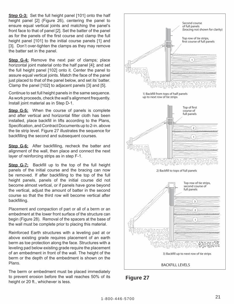
Step G-5: When the course of panels is completeand after vertical and horizontal filter cloth has beeninstalled,placebackfill in liftsaccording to thePlans,Specification,andContractDocumentsupto2-in.abovethetiestriplevel.Figure27illustratesthesequenceforbackfillingthesecondandsubsequentcourses.
Step G-6: After backfilling, recheck the batter andalignmentofthewall,thenplaceandconnectthenextlayerofreinforcingstripsasinstepF-1.
1
1
2
1
2
3
Top row of tie strips,�rst course of full panels
Second courseof full panels(bracing not shown for clarity)
1) Back�ll from tops of half panelsup to next row of tie strips
Top of �rstcourse offull panels
2) Back�ll to tops of full panels
Top row of tie strips,second course of full panels
3) Back�ll up to next row of tie strips
BACKFILL LEVELS
Figure 27
Step G-4: Remove the next pair of clamps; placehorizontaljointmaterialontothehalfpanel[4];andsetthefullheightpanel[102]ontoit.Centerthepaneltoassureequalverticaljoints.Matchthefaceofthepaneljustplacedtothatofthepanelbelow,andsetits’batter.Clampthepanel[102]toadjacentpanels[3]and[5].
Step G-7: Backfill up to the top of the full heightpanels of the initial course and the bracing can nowbe removed. If after backfilling to the top of the fullheight panels, panels of the initial course did notbecomealmostvertical,orifpanelshavegonebeyondthevertical,adjusttheamountofbatterinthesecondcoursesothat thethirdrowwillbecomeverticalafterbackfilling.
Placement and compaction of part or all of a berm or an embedmentatthelowerfrontsurfaceofthestructurecanbegin(Figure28).Removalofthespacersatthebaseofthewallmustbecompletepriortoplacingthismaterial.
ReinforcedEarth structureswith a leveling pad at orabove existing grade requires placement of an earthbermastoeprotectionalongtheface.Structureswithalevelingpadbelowexistinggraderequiretheplacementofanembedmentinfrontofthewall.TheheightofthebermorthedepthoftheembedmentisshownonthePlans.
Thebermorembedmentmustbeplacedimmediatelytopreventerosionbeforethewall reaches50%of itsheightor20ft.,whicheverisless.

22 www.re in fo rcedear th .com
H. Completion of the Wall
Step H-1:Inplacingtopcoursepanels,theconstructionsequencecontinuesaspreviouslyoutlined.However,top course panels have either a flat or a slopingedgeandmaybesuppliedinvaryingheightstomeetfinished-elevation requirements. Special care shouldbe exercised in placement of top panels exceeding 6 ft. inheight.Asufficientcrewsizeshouldbeprovidedtosafelyinstallandbracelargeheightpanels,particularlyinhighwindandinclementweatherconditions.RefertothePlansforthelocationofspecifictoppanels.Step H-2: After backfilling is complete, remove allclampsandwoodenwedgesfromthestructure.Step H-3: Install top wall treatment. If required. Several typesarecommonlyused:• Cast-in-Place - If required, rebar for connection will
protrudefromtoppanels.Allnecessaryattachmentdetailsforabarrier,coping,parapet,orpavedditchwillbeshownintheplans.
• Precast Coping - If approved, precast coping will besupplied.AttachmentdetailswillbeshowninthePlans.
• Plain-Thetopofpanelswillremainexposedwithno further treatmentnecessary.Sometimescalledstepped top.
Panelbattershouldbecheckedafterbackfillingeachcoursewithnecessaryadjustmentsmadeinsubsequentcourses to ensure plumbness.
Quality control requirements for Select GranularBackfilling, includingdensityandplacementmoisture,arethesameforthesecondandsubsequentcoursesasforthefirstcourse,unlessotherwiseindicatedinthePlansorSpecifications.
At least two, but no more than three rows of panel wedges should remain in place at all times during erection. When construction is complete, all wedges must be removed.
Finishgrade
Originalgrade
(a) Berm in front of wall
Originaland �nishgrade
(b) Embedment
WALL TOE PROTECTION
Figure 28
Step G-8:Whenbackfill reaches the topof the initialcourseof fullpanels(which ishalfwayupthesecondcourse),beginplacingthenextcourseofpanels.
Repeat steps G-1 throughG-5 for panel installation,backfill placement and compaction, reinforcing stripinstallation, and placement of horizontal/verticaljoint materials. Follow these same procedures forthe second and subsequent panel courses until thestructure is ready to be topped off. Bracing may beused on all subsequent courses, if practical, to assist withmaintainingbatterandwallalignmentaswellasprovidingadditionalstabilitytothestructureduringtheconstruction process.
Aftertheerectionofeachcourseofpanels,thewoodenwedges of that course and the two courses below itshould be checked to ensure that they are securelyseated.

231-800-446-5700
ReinforcedEarthstructuresaretobeerectedinstrictcompliancewiththestructuralandaestheticrequirementsofthePlans,Specifications, and Contract Documents. The desired results can be achieved through the use of quality materials, correctconstructionprocedures,andproperinspection.However,consideringthenatureofconstructionwork,theremaybeoccasionswhendimensionaltolerancesand/oraestheticlimitsareexceeded.Correctivemeasuresmustbetakenimmediatelytoreturnthestructure to acceptable tolerances.
VI. Condition-Cause Relationships
CAUSECONDITION 1. Distortion in Wall
(a)Differentialsettlementorlowspotinwall(b)Overallwallleaning(c)Panelcontact,resultinginspalling/chipping
2.(a)Firstcoursedifficulttosetand/ormaintain level.
(b)Panel-topanelcontactresultinginspalling and/orchipping.
3. Wall Leaning Out
4. Wall Leaning In
5. Wall Out of Horizontal Alignment Tolerance, or Bulging
6. Panels Do Not Fit Properly in IntendedLocations Resulting In Subsequent Panels Spalling or Chipping
Foundation (subgrade) material too weak or wet forproperbearing.Iffillmaterial,poorqualityorimpropercompaction.
Levelingpadnotwithintolerance.
a) Panelsnotbatteredsufficiently.b) Largebackfillplacingand/orcompaction
equipmentworkingwithin3-ft.zoneofbackofwall.c) Backfillmaterialplacedwetofoptimummoisture
content.d) Backfillcontainsexcessivefinematerials(beyond theSpecificationsforpercentofmaterialspassing
aNo.200sieve).e) Backfillmaterialpushedagainstbackofwall before being compacted on strips.f) Excessiveorvibratorycompactiononuniform
finesand(morethan60percentpassingaNo.40sieve).
g) Backfillmaterialdumpedclosetofreeendofreinforcingstrips,thenspreadtowardsbackofwall,causingbulgeinstripsandpushingpanelout.
h) Wedgesnotseatedsecurely.i) Clampsnottight.j) Excessivecompactiveeffort.k) Excessiveliftthickness.l) Plasticityindexofbackfillmaterialinexcessof
specificationlimits.
a) ExcessivebattersetinpanelsforSelectGranularBackfillmaterialbeingused.
b) Inadequatecompactionofbackfill.
(a)Seecauses3C-G,and3I.(b)Backfillsaturated(heavyrainorimpropergradingofbackfillaftereachday’soperation).
(a)Panelsarenotlevel.(b)Differentialsettlement(seeCondition1).(c)Failuretousespacersbetweenpanels.(d)Levelingpadincorrect.

24 www.re in fo rcedear th .com
VII. Appendix
A. Facing Panel Types and Nomenclature
A. Panel Designations: Alldesignand/orshopdrawings,andprecastpanels,aredesignedasfollows:
Key to Panel Designation: XX – X – RX – X.XX
BasicPanelTypePanelModificationNumberofTieStrips Panel ReinforcementPanelWidth OrDeflectionAngle(forbentpanels) Where(X)canbealetterordigit
251-800-446-5700
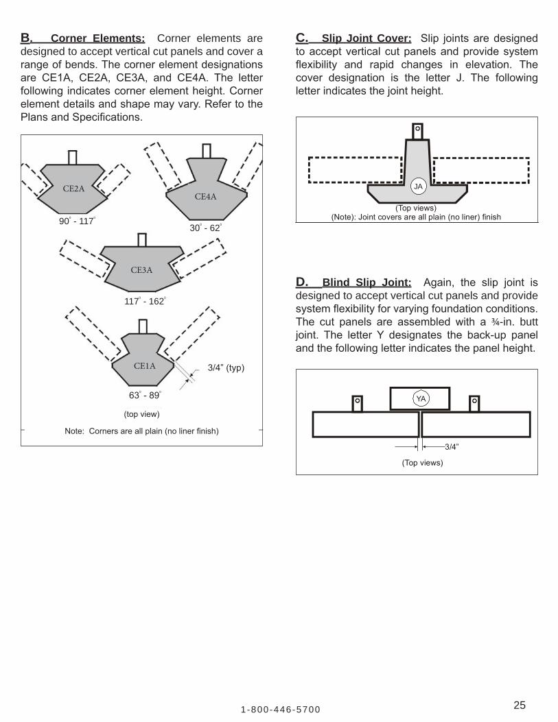
C. Slip Joint Cover: Slip jointsaredesignedtoacceptverticalcutpanelsandprovidesystemflexibility and rapid changes in elevation. Thecover designation is the letter J. The followingletterindicatesthejointheight.
D. Blind Slip Joint: Again, the slip joint isdesigned to accept vertical cut panels and provide systemflexibilityforvaryingfoundationconditions.The cut panels are assembled with a¾-in. butt joint. The letter Y designates the back-up panelandthefollowingletterindicatesthepanelheight.
(Topviews)
YA
3/4”
(Topviews)
JA
(Note):Jointcoversareallplain(noliner)finish
B. Corner Elements: Corner elements are designed to accept vertical cut panels and cover a rangeofbends.Thecornerelementdesignationsare CE1A, CE2A, CE3A, and CE4A. The letterfollowingindicatescornerelementheight.Cornerelementdetailsandshapemayvary.RefertothePlansandSpecifications.
CE2ACE4A
CE3A
CE1A
900 - 1170 300 - 620
1170 - 1620
630 -890
3/4”(typ)
(topview)
Note:Cornersareallplain(nolinerfinish)

26 www.re in fo rcedear th .com
B. Glossary of Terms
Agency
Contract Documents
Contractor
Engineer
Inspector
Owner
Plans
Specifications
Technical Advisor
Work
Theperson(s),firm,orcorporationactingasAgentfortheOwner.
TheOwner-Contractagreement,includingtheconditionsoftheContract(general,supplementary,andotherconditions),thedrawings,Specificationsand the provisions of the agreement between the Contractor andTheReinforcedEarthCompany;andalsoincludingalladdendaissuedpriortoexecutionoftheContract,allmodificationstheretoandanyotheritemsspecificallystipulatedasbeingincludedintheContractDocuments.
Theindividual,firmorcorporationundertakingtheexecutionoftheWorkunderthetermsoftheContract,andactingdirectlythroughitsAgentsoremployees.
Theperson(s)designatedbytheOwner,ashavingauthoritativechargeovercertainspecificengineeringoperationsandduties.
TheauthorizedrepresentativeassignedtomakeadetailedinspectionofanyorallportionsoftheWorkormaterialsthereofintheOwner’sbehalf.
TheOwnerofaproject.Theagency,person,firmorcorporationwithwhichaContracthasbeenmadeforthepaymentoftheWorkperformedundertheContract.
The official approved plans, profiles, typical cross sections, workingdrawings and supplemental drawings, or exact reproductions thereof,whichshowthelocations,character,dimensionsanddetailsoftheWorkto be performed.
Adescription, forcontractpurposes,of thematerialsandworkmanshiprequiredinastructure(s),asalsoshownontherelatedworkingdrawings.The written material containing the standard provisions and specialprovisions,asmaybenecessary,pertainingtothequantitiesandqualitiesofmaterialstobefurnishedundertheContract.
RepresentativeofTheReinforcedEarthCompanywhomaybeavailabletoassist theContractorwithmaterial schedulingandcoordination,andgiveadviceontherecommendedconstructionproceduresapplicabletoReinforcedEarthstructuresassetoutinthismanual.
TheentirescopeoftheWorktobeperformedatthesiteoftheconstructionproject including labor, materials, equipment, transportation and suchotherfacilitiesasarenecessarytofulfillallobligationsundertheContract.

271-800-446-5700
C. Safety Tips for Unloading Reinforced Earth Products
1. Uponarrivaloftruck,examinetheloadforanyshiftingorunstableconditionspriortoremovingtie downs. 2. Thetruckshouldbeonlevelgroundwhenunloading.Unloadingonunlevelgroundcouldresult inshiftingofpanelsorpossiblypanelsfallingfromtrailer. 3. Liftingequipment(straps,cables,ringclutches,etc.)shouldbecheckedforexcessivewearor crackingpriortounloadingtruck. 4. Donotmovethetractorwhileproductisnottieddown. 5. Ifdriversarerequiredtoremovechainsorbindersnexttolaneofmovingtraffic,conesand flagmanshouldbeusedtodirecttrafficawayfromthetraileranddriver. 6. Driversarenottrainedasriggersorswampersandshouldstayincaborclearawayfromunloading operations.Thedriversareactinginadeliverycapacityonly. 7. Personalprotectiveequipmentrequiredbythegeneralcontractoronsiteshouldalsoberequiredof deliverydrivers. 8. Personnelshouldnotbeallowedunderasuspendedload. 9. Onceremovedfromthetrailer,panelsnotplaceddirectlyinthewallshouldbestackedorsecuredon flatgroundtopreventtippingorfalling. 10. Areasbetweenthetruckandcraneshouldberestrictedtopersonnelrequiredtounloadtrailer. 11. IfanyunsafesituationsexistwhileloadingorunloadingRECoproducts,contactThe ReinforcedEarthCompanyimmediatelytoeliminateanyhazardsorexposuretoillnessorinjury.

28 www.re in fo rcedear th .com
D. The Reinforced Earth Company Offices
TheReinforcedEarthCompanymaintainsfull-serviceofficesthroughouttheUnitedStates.Contacttheofficeservingyourareafortechnicalservice:
SoutheastRegion Atlanta,GA (770)242-9415
NortheastRegion Boston,MA (978)664-2830
CentralRegion Dallas,TX (817)283-5503 Midwest Chicago,IL (630)898-3334 SouthwestRegion SanDiego,CA (858)576-2400
WesternRegion Denver,CO (303)790-1481
Central-Northeast&Mid-AtlanticRegion Reston,VA (703)547-8797
FloridaRegion Orlando,FL (407)226-2840
Corporate HeadquartersTheReinforcedEarthCompany12001SunriseValleyDr.,Ste400
Reston, VA 20191
Telephone:(703)547-8797or(800)446-5700
www.reinforcedearth.com
SAFETY BULLETINFebruary25,2014
Re: Safety Reminder for Reinforced Earth® Panel Installation
PleasereviewtheReinforcedEarth®ConstructionManualcarefullyandpracticesafetyinallaspectsofhandlingandinstallingReinforcedEarthwallmaterials.Thefollowingprovidesimportantsafetyreminderswhenhandlingandinstallingwallpanels:
1.Panelsatthelevellingpadcourseshouldbeexternallybracedasshownintheconstruction manual upon installation and before additional panels are installed.
2.Panelsmustremainattachedtoliftingequipmentuntilsuchtimeasexternalbracing,wedgesandshoulderclampsareinplaceandsecured.
3.Allsubsequentpanelsmustremainattachedtotheliftingequipmentuntilalignmentadjustmentshavebeenmadeandwedgesandclampshavebeeninstalledandsecured.
4.Cutpanelsadjacenttoacast-in-placestructurerequirespecialattention.Bracing,wedgingandclampingisrequiredbeforereleasingthepanelfromtheliftingequipment.Timberorsteelanglecanbeanchoredtotheverticalsurfaceoftheadjacentcast-in-placestructureandthenthecutpanelcanbewedgedandclampedtothesecuredtimberorangle.
5.Thelastpanelatthefreeendofwallshouldbeexternallybracedonthefreeendaswellassecuredwithwedgesandaclamptotheadjacentpanel.
Pleaseensureyourcrewisawareoftheabovesafetyreminders.

Corporate Headquarters12001SunriseValleyDr.,Ste400
Reston, Virginia 20191800.446.5700
www.reinforcedearth.com
REINFORCED EARTH


![Fatigue of a Rectangular Reinforced Concrete CS - …...Fatigue of a Rectangular Reinforced Concrete CS Combination calculatoric forces and moments at ‚= 5.0m: LC Vy[kN] Vz[kN] My[kNm]](https://static.fdocuments.in/doc/165x107/5ec001511c97f46f10127c66/fatigue-of-a-rectangular-reinforced-concrete-cs-fatigue-of-a-rectangular-reinforced.jpg)