Reinforced Concrete Structures - School of Engineeringengineering.sfsu.edu/download/Seismic6.pdf ·...
47
1 Reinforced Concrete Structures Outline Basics of Reinforced Concrete Types of Reinforced Concrete Structures Deficiencies Rehabilitation Strategies Hyatt, Baguio, Phillipine Islands, 1991
Transcript of Reinforced Concrete Structures - School of Engineeringengineering.sfsu.edu/download/Seismic6.pdf ·...
1
Reinforced Concrete Structures
Outline
Basics of Reinforced ConcreteTypes of Reinforced Concrete StructuresDeficienciesRehabilitation Strategies
Hyatt, Baguio, Phillipine Islands, 1991
2
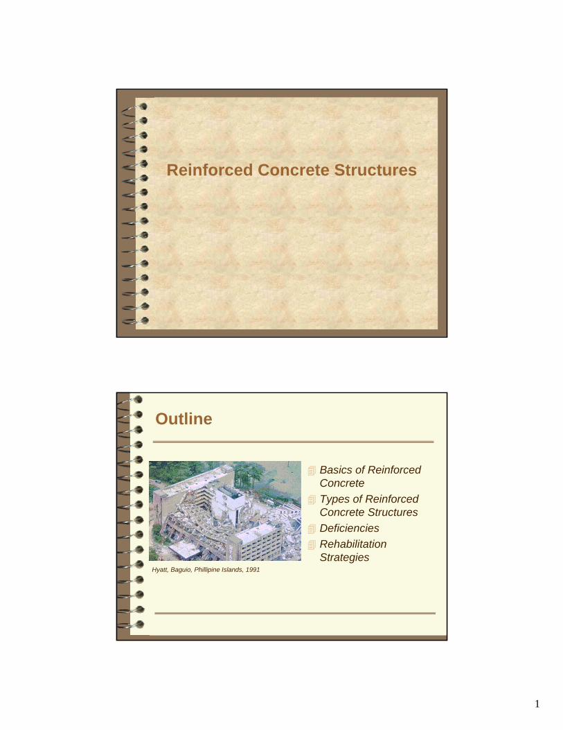
Properties of Concrete
Mixture of:– paste
• cement & water– coarse aggregate
• crushed rock– fine aggregate
• sand
Strong in Compression
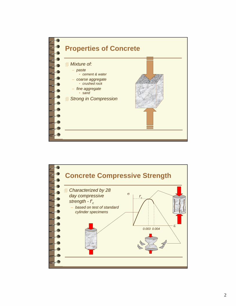
Concrete Compressive Strength
Characterized by 28 day compressive strength - f’c– based on test of standard
cylinder specimens
σ
ε
f’c
0.003 0.004

3
Concrete Compressive Strength
Early concrete f’c~2,000 psiModern concrete– western U.S.
3,000 psi < f’c < 6,000 psi– eastern U.S.
f’c ranges to 20,000 psi
Increasing compressive strength generally corresponds to more brittle behavior
σ
ε
f’c
Concrete Compressive BehaviorMore ductile behavior can be obtained by:– delaying onset of large
negative stiffness in concrete
– achieved by confinement• can increase compressive
strength• can increase ultimate
compressive strain ~0.015
σ
ε
f’c
Effect of confinement

4
Tensile Properties of Concrete
Concrete is weak in tension– cracks– pulls apart
Modulus of rupture typically taken as 7.5√ f’c for normal weight concrete
5√ f’c for light weight concrete
Reinforcing Steel
Steel has good tension strengthProvides reinforced concrete with stiffness and strength in tension
• Prevents cracks from opening andhelps concrete retain its strength

5
Reinforcing Steel
For the reinforcing to be effective, tension must transfer from concrete to steel
This mechanism is known as bond
Modern steel has deformations to increase bond older steel (pre-1930 did not)
Reinforcing for Concrete Compression
Concrete is strong in compressionUnder extreme loads:– split– spall– crush

6
Confinement Steel
Binds concrete togetherPrevents vertical splitting under compression– effectively decreases
onset of negative stiffness
Delays crushing
Confinement Steel
Confinement is achieved through Poisson effects– as concrete compresses,
it grows in the transverse direction
– hoop steel confining the inner core must also grow
– hoops develop tension as they grow
– induces compression as secondary principal stress

7
Confinement Steel
Most efficient form of confinement steel is a continuous round hoop
This is approximated byspiral reinforcement
Confinement Steel
Confinement can be approximated by rectangular ties
Cross ties improve effectiveness of rectangular ties

8
Confinement Steel
To be effective, confinement steel must be– closely spaced (~4”)– developed for tension
inside the confined core of the member
• 135 degree minimum hooks
Confined core
Flexure
Combined influence of compression and tension on different faces of memberCracks tensile faceYields or debondstensile steelCrushes compressive faceBuckles compressive steel
9
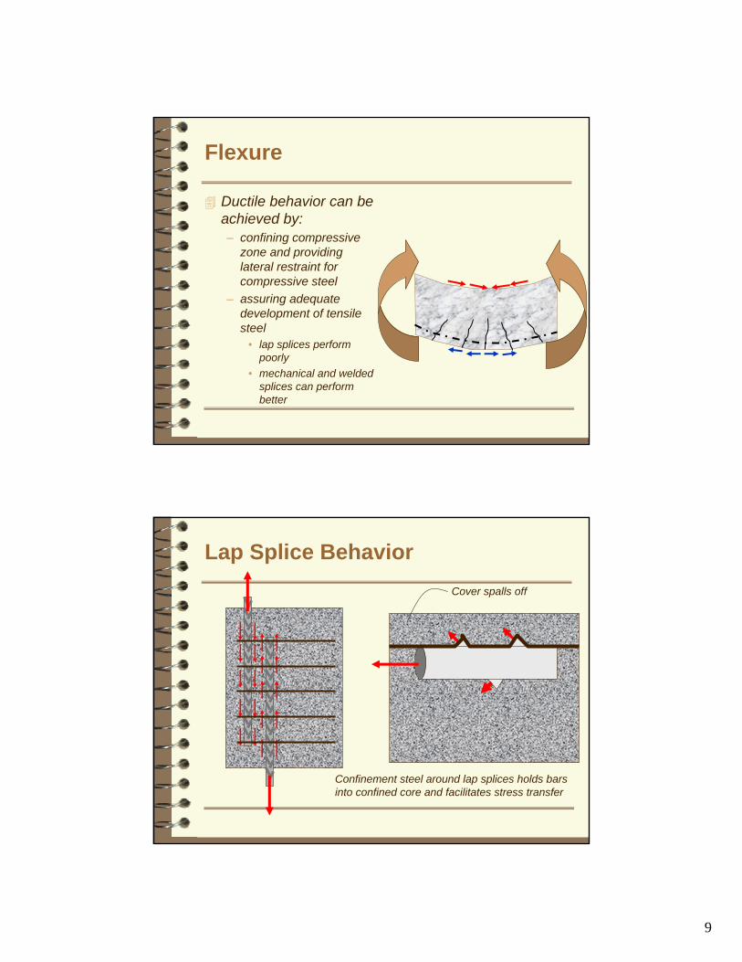
Flexure
Ductile behavior can be achieved by:– confining compressive
zone and providing lateral restraint for compressive steel
– assuring adequate development of tensile steel
• lap splices perform poorly
• mechanical and welded splices can perform better
Lap Splice BehaviorCover spalls off
Confinement steel around lap splices holds bars into confined core and facilitates stress transfer
10
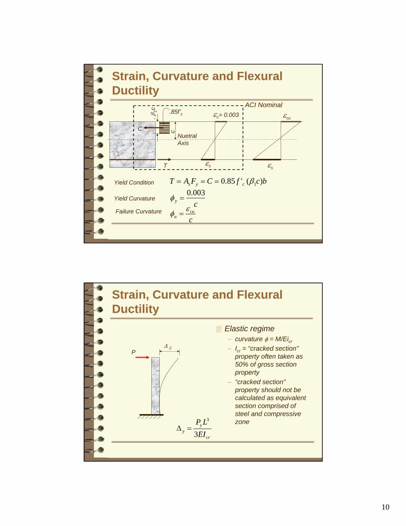
Strain, Curvature and Flexural Ductility
bcfCFAT cys )('85.0 1β===Yield Condition
NuetralAxis
c
. β1c .85f’c
T εs
εc= 0.003
C
Yield Curvaturecy003.0
=φFailure Curvature
εcu
εs
ccu
uεφ =
ACI Nominal
Strain, Curvature and Flexural Ductility
Elastic regime– curvature φ = M/Eicr
– Icr = “cracked section”property often taken as 50% of gross section property
– “cracked section”property should not be calculated as equivalent section comprised of steel and compressive zone
∆ ΕP
cr
yy EI
LP3
3
=∆

11
Cracked section properties
Equivalent section, consisting of steel area in tension and concrete compressive zone
exists only, locally at cracks
In between cracks, more of concreteis effective, both in tension and compressionresulting in more rigid section
Appropriate cracked section properties mustaccount for the “average”section properties considering cracked anduncracked zones
Strain, Curvature and Flexural Ductility
∆
Plastic regime– all plastic curvature is assumed to
be accommodated within a discrete zone around the yield area known as the “hinge zone”
– hinge zone typically assumed to have a length ranging from d/2 to d
P
Plastic hinge zonelength = Lp
L
p
T
pyT
ppp
LL
∆∆=
∆+∆=∆
⎟⎠⎞
⎜⎝⎛ −=∆
µ
φ 2

12
Stress Strain Relationships: Steel
( ) ( )⎥⎥⎦
⎤
⎢⎢⎣
⎡
−−
−−⎟⎠⎞
⎜⎝⎛ −+
+
⎥⎥
⎦
⎤
⎢⎢
⎣
⎡+
=p
shsu
ssuysu
shs
y
ss
sss ffsign
fE
Efεεεεεε
ε
ε 12
1
1
05.020
fy
εy
ACI
fy
εy
fsu
εsh εsu εsu
Real
ysu
shsush ff
Ep−−
=εε
Esh
Es
Various Grades of Reinforcement

13
Concrete Stress Strain Relation:
Mander et al. (1989)
Steel Stress Strain Relation:
0
1
2
3
4
5
6
7
8
9
10
0.000 0.005 0.010 0.015 0.020 0.025
Strain
Stre
ss
Unconfined Cover Confined
Conservative estimate of ultimate strain governed by hoop fracture (Priestley et al.)
cc
suyhscu f
f'
4.1004.0
ερε +=
f’c
f’cc

14
Confinement of Circular Columns
cc
e
AA
ek =
Confinement Effectiveness Coeff
Area of Core Concrete
Effectively Confined Core
)1(4
2ccscc dA ρπ
−=
απ
⎟⎟⎠
⎞⎜⎜⎝
⎛−=
sse d
sdA2
'14
2
α = 2 for circular hoops;1 for spirals
s
sp
s
ssps ds
Ads
dAConcreteofVol
SteelofVol 44/..
.2 ===
ππ
ρ
eslysp kdsffA ×= '2
yjs
jacketysel f
dt
fkf2
21' == ρ
Asp fy Asp fyf’l
From free body diagram
Define volumetric ratio of lateral steel:slyjjacket dfft 112 ' ×=×
Therefore,
Confinement of Circular Columns
15
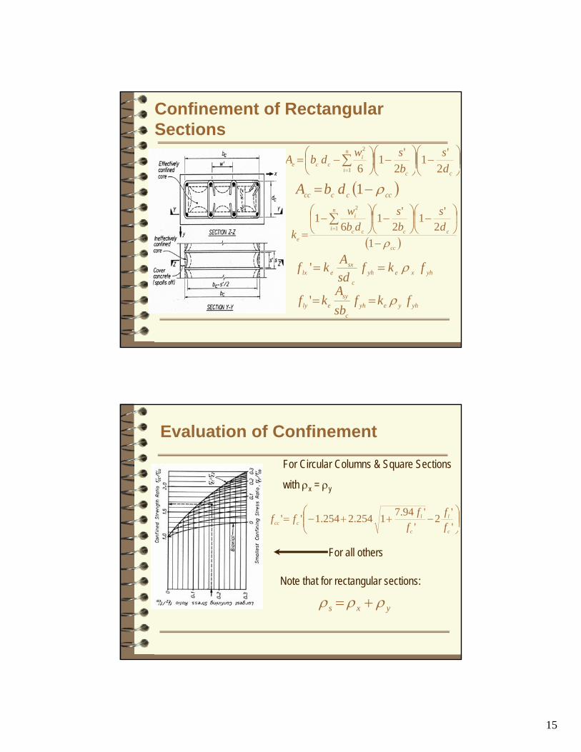
Confinement of Rectangular Sections
⎟⎟⎠
⎞⎜⎜⎝
⎛−⎟⎟
⎠
⎞⎜⎜⎝
⎛−⎟
⎠⎞
⎜⎝⎛ −= ∑
= cc
n
i
icce d
sbswdbA
2'1
2'1
61
2
( )cccccc dbA ρ−= 1
( )cc
cc
n
i cc
i
e
ds
bs
dbw
kρ−
⎟⎠
⎞⎜⎝
⎛−⎟
⎠
⎞⎜⎝
⎛−⎟
⎠
⎞⎜⎝
⎛−
=∑
=
12
'12
'16
11
2
yhxeyhc
sxelx fkf
sdAkf ρ=='
yhyeyhc
syely fkf
sbA
kf ρ=='
Evaluation of Confinement
⎟⎟⎠
⎞⎜⎜⎝
⎛−++−=
''2
''94.71254.2254.1''
c
l
c
lccc f
ff
fff
For Circular Columns & Square Sections
with ρx = ρy
For all others
Note that for rectangular sections:
yxs ρρρ +=
16
Moment Curvature Analysis
Shows variation of sectional moment against increasing curvatureUseful for evaluating ductility capacity of a sectionM-φ analysis is for a constant axial load onlyMaximum moments from M-φ analyses for various P s can be used to generate overstrength P-M interaction curve
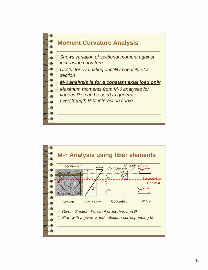
M-φ Analysis using fiber elements
Given: Section, f’c, steel properties and PStart with a given φ and calculate corresponding M
εu Confined σ−εUnconfined σ−ε
ysi
Section Strain Dgm Concrete σ Steel σ
c Neutral Axis
φ
yci
Fiber element
Centroid

17
Assumptions of M-φ Analysis
Plane sections remain plain before and after bendingWhen compression strain exceeds spallingstrain strain, cover is lost and stress in cover = 0.Concrete does not have strength in tensionBond slip ignoredTransverse steel prevents bar buckling & so compression capacity of steel is maintained
M-φ Analysis; Steps
Step 1: For a given φ assume a neutral axis depth cStep 2: Create the strain diagram and find the strains at the various steel locations and center of the compression fibersStep 3: Integrate the stresses to find the axial load
ssc TCCP −+=
∑∑∑===
++=ns
jsjsj
nc
iccicci
nc
icici AfAfAfP
111

18
Step 4; Check P (=Pcalc)against given P.If P-Pcalc > tolerance go back to step 1 and start with a new “c”. However, if P-Pcalc <= tolerance , go to step 5
Step 5: Calculate moment M
sj
ns
jsjsj
nc
iciccicci
nc
icicici yAfyAfyAfM ∑∑∑
===
++=111
Step 6: Choose next φ and repeat
M-f Analysis; Steps
Effect of Confinement on M-φ

19
Effect of Axial Load on M-φ
Axial Load Moment Interaction
P1
P2
P
M
M
φ
φ
M
Overstrength P-M Interaction
ACI Nominal P-M Interaction
ACI Design P-M Interaction

20
Shear
Results from non-aligned, equal but opposite forces
Tends to push elements “out of square”
Is a natural by-product of non-uniform flexure in a structural member
Effects of Shear
Results in diagonal crack patterns in walls
Results in cracks inclined at 45o in beams and columns

21
Effects of Shear
Shear forces must always be in equilibriumDiagonal between “effective” point of application of these balanced shear forces defines the principal stress planes
•Principal Compression Stress
•Principal Tensile Stress
Effects of Shear
Classical diagonal “shear” crack is really a principal tensile stress crackShear behavior can be conceived as a diagonal compressive behavior, rather than a pure “shear” behavior
22
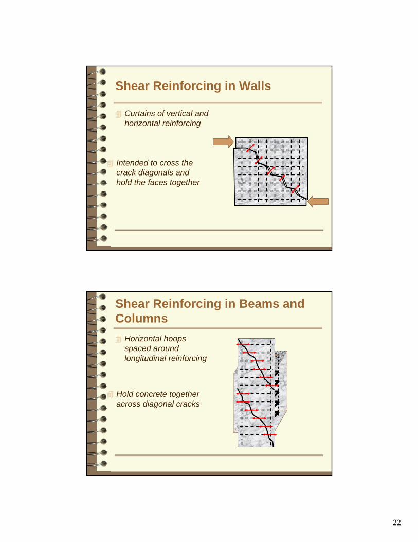
Shear Reinforcing in Walls
Curtains of vertical and horizontal reinforcing
Intended to cross the crack diagonals and hold the faces together
Shear Reinforcing in Beams and Columns
Horizontal hoops spaced around longitudinal reinforcing
Hold concrete together across diagonal cracks
23
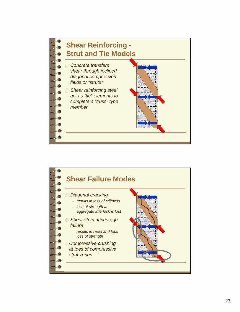
Shear Reinforcing -Strut and Tie Models
Concrete transfers shear through inclined diagonal compression fields or “struts”
Shear reinforcing steel act as “tie” elements to complete a “truss” type member
Shear Failure Modes
Diagonal cracking– results in loss of stiffness– loss of strength as
aggregate interlock is lost
Shear steel anchoragefailure– results in rapid and total
loss of strength
Compressive crushing at toes of compressive strut zones

24
Shear Strength of Beam-Columns
pscn VVVV ++=
θcots
DfAV yhv
s
′=
θπ cot2 s
DfAV yhv
s
′=
ecc AfkV '= grosse AA 8.0=
αtanPVp =
Circular
Rectangular
θ typically ranges between 30 to 35 degrees
Concrete Shear Strength Vc
Priestley et al.(1996)
25
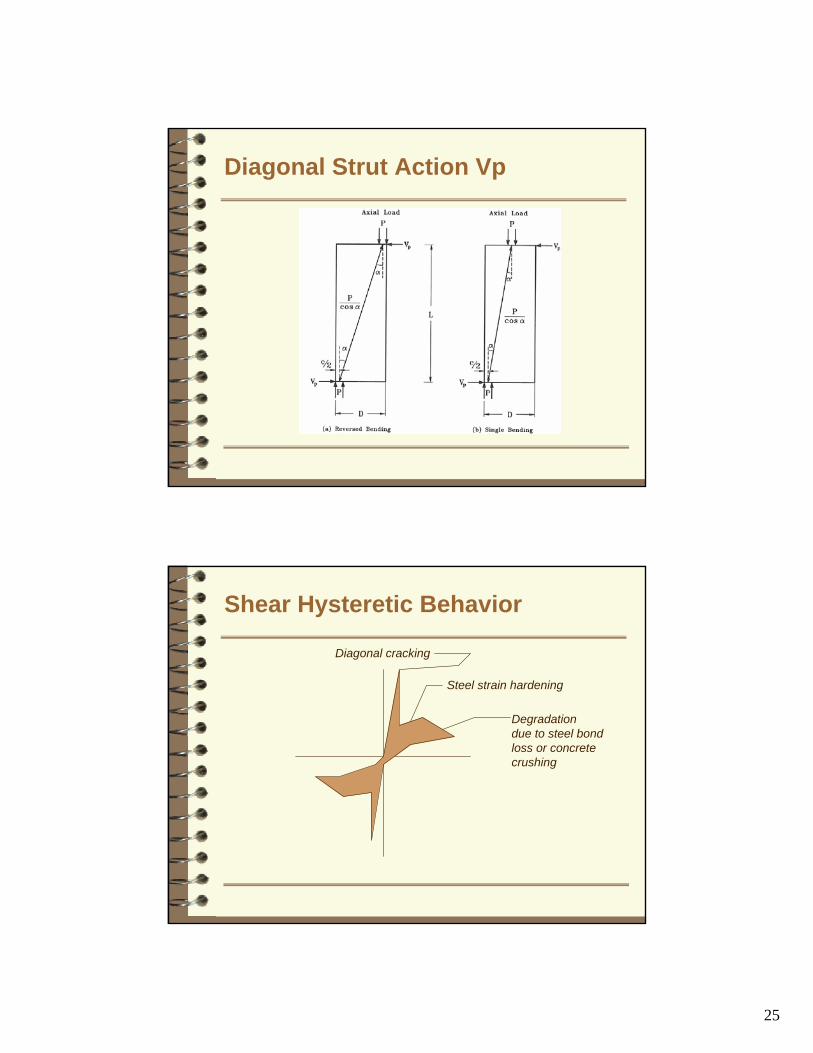
Diagonal Strut Action Vp
Shear Hysteretic Behavior
Diagonal cracking
Steel strain hardening
Degradationdue to steel bondloss or concretecrushing
26
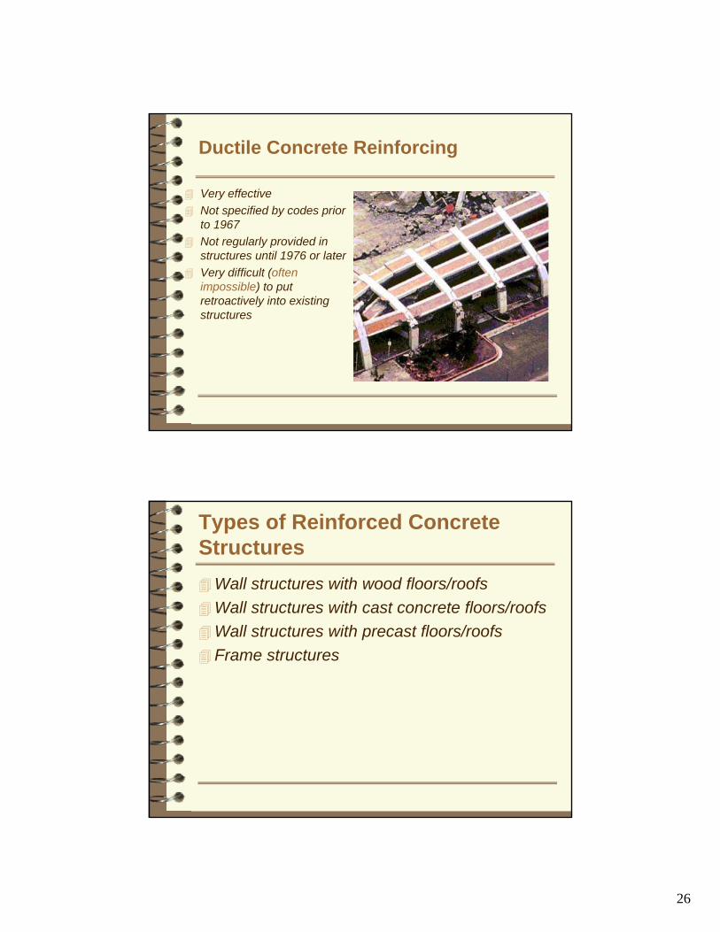
Ductile Concrete Reinforcing
Very effectiveNot specified by codes prior to 1967Not regularly provided in structures until 1976 or laterVery difficult (often impossible) to put retroactively into existing structures
Types of Reinforced Concrete Structures
Wall structures with wood floors/roofsWall structures with cast concrete floors/roofsWall structures with precast floors/roofsFrame structures
27
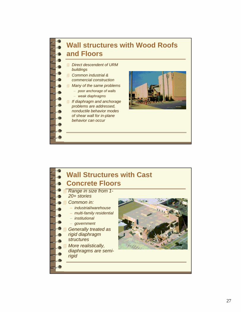
Wall structures with Wood Roofs and Floors
Direct descendent of URM buildingsCommon industrial & commercial constructionMany of the same problems– poor anchorage of walls– weak diaphragms
If diaphragm and anchorage problems are addressed, nonductile behavior modes of shear wall for in-plane behavior can occur
Wall Structures with Cast Concrete FloorsRange in size from 1-20+ storiesCommon in:– industrial/warehouse– multi-family residential– institutional– government
Generally treated as rigid diaphragm structuresMore realistically, diaphragms are semi-rigid
28
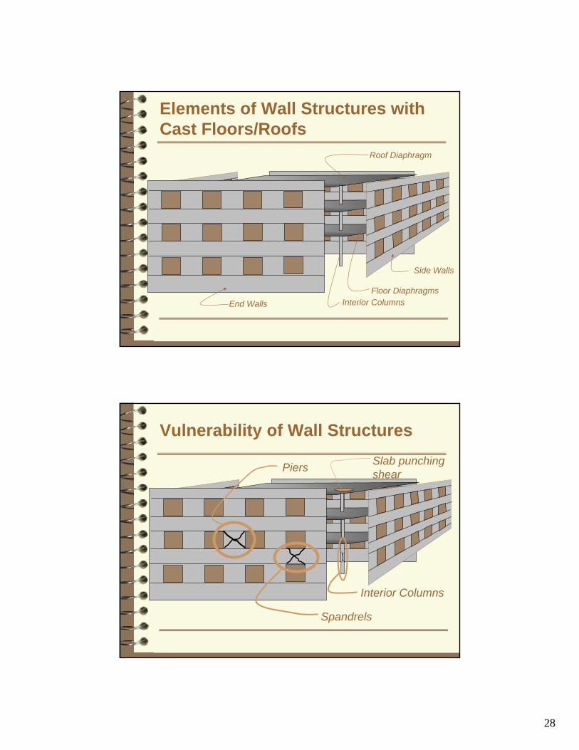
Elements of Wall Structures with Cast Floors/Roofs
End Walls
Side Walls
Roof Diaphragm
Floor DiaphragmsInterior Columns
Vulnerability of Wall Structures
Piers
Spandrels
Interior Columns
Slab punchingshear

29
Vulnerability of Wall StructuresPiers
Spandrels
Interior Columns
Slab punchingshear
Although many of these behavioral modes are quite brittle, performance of these structures is highly dependent on induced deformationGood behavior is obtained by ensuring that deformation induced by design earthquake does not exceed failure deformation for critical elements
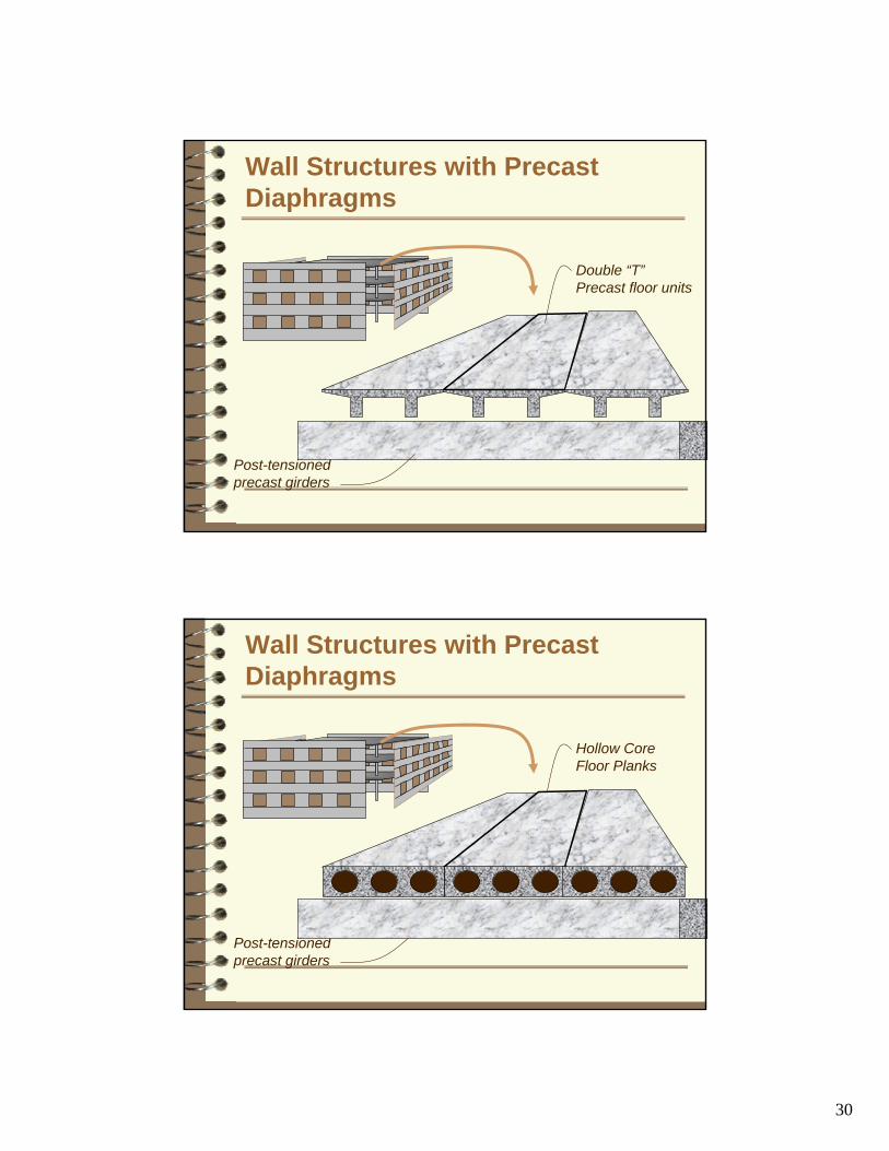
Wall Structures with PrecastDiaphragms
Common in industrial applicationsSimilar to other Wall structures, but has poor continuity and no formal diaphragms unless topping slab providedIf topping slab is present, behaves as rigid or semi-rigid diaphragm building
30
Wall Structures with PrecastDiaphragms
Double “T”Precast floor units
Post-tensionedprecast girders
Wall Structures with PrecastDiaphragms
Hollow CoreFloor Planks
Post-tensionedprecast girders

31
Concrete Frame
Became popular in 1950sUsed for many large structures in 1960sCommon in office and institutional occupancies
Elements of Concrete Frames
Exterior Columns
Exterior Spandrels
Floor and Roof Slabs
Interior Columns
32
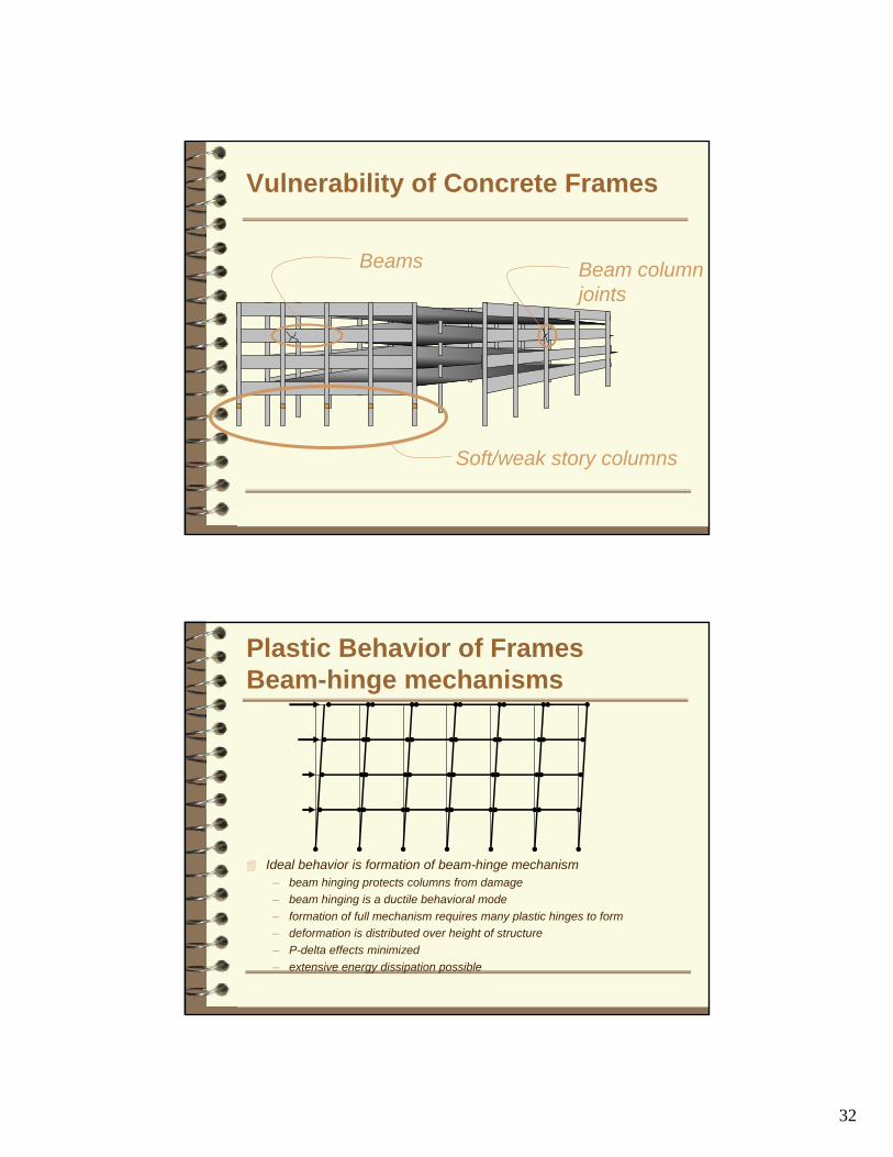
Vulnerability of Concrete Frames
Soft/weak story columns
Beam column joints
Beams
Plastic Behavior of FramesBeam-hinge mechanisms
Ideal behavior is formation of beam-hinge mechanism– beam hinging protects columns from damage– beam hinging is a ductile behavioral mode– formation of full mechanism requires many plastic hinges to form– deformation is distributed over height of structure– P-delta effects minimized– extensive energy dissipation possible
33
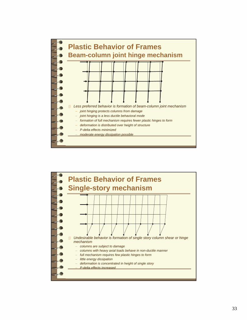
Plastic Behavior of FramesBeam-column joint hinge mechanism
Less preferred behavior is formation of beam-column joint mechanism– joint hinging protects columns from damage– joint hinging is a less ductile behavioral mode– formation of full mechanism requires fewer plastic hinges to form– deformation is distributed over height of structure– P-delta effects minimized– moderate energy dissipation possible
Plastic Behavior of FramesSingle-story mechanism
Undesirable behavior is formation of single story column shear or hinge mechanism
– columns are subject to damage– columns with heavy axial loads behave in non-ductile manner– full mechanism requires few plastic hinges to form– little energy dissipation– deformation is concentrated in height of single story– P-delta effects increased

34
Frame Behavioral Modes
Many older concrete frames are subject to single-story behavioral modes– short column (shear
sensitive columns)• inadequate horizontal
reinforcing• presence of
architectural elements that shorten effective span
Methods of Strengthening & Stiffening
• Shear Walls• Economical and effective (very stiff and strong)• May be placed on interior or exterior• Often have significant architectural impact• Can be blended with existing architecture
35
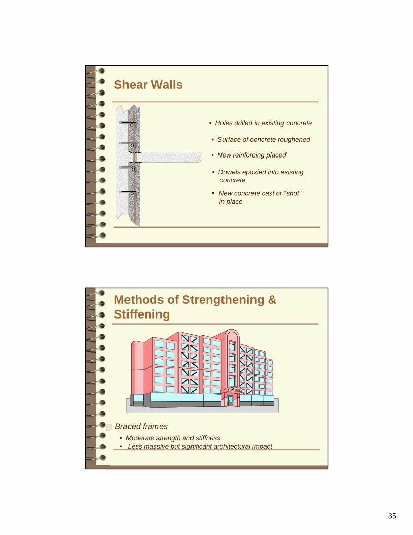
• New concrete cast or “shot”in place
Shear Walls
• Holes drilled in existing concrete
• Surface of concrete roughened
• New reinforcing placed
• Dowels epoxied into existingconcrete
Methods of Strengthening & Stiffening
Braced frames• Moderate strength and stiffness• Less massive but significant architectural impact
36
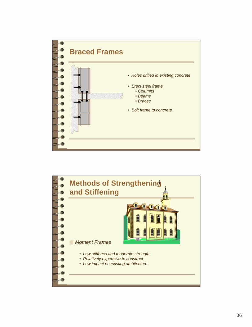
Braced Frames
• Holes drilled in existing concrete
• Erect steel frame• Columns• Beams• Braces
• Bolt frame to concrete
Methods of Strengtheningand Stiffening
Moment Frames
• Low stiffness and moderate strength• Relatively expensive to construct• Low impact on existing architecture

37
• New concrete cast in place
Moment Frames
• Surface of concrete roughened
• Dowels epoxied into existingconcrete
• Holes drilled in existing concrete
• New reinforcing placed
Energy Dissipation
Very effective upgrade for concrete framesInstalled as part of a braced frame systemMore costly than standard braced framesMaintenance required over life

38
Energy Dissipation Devices
F
D
Friction
F
D
Fluid ViscousVisco Elastic
F
D
Hysteretic
Energy Dissipation Devices
Always installed as part of braced frameMore expensive then braced framesBetter performance than braced framesCan effectively reduce seismic response by 50%

39
Energy Dissipation Devices
Fluid viscous dampersFriction dampersHysteretic dampers– ADAS– Unbonded Braces
Viscoelastic dampers
Seismic Isolation
Fixed - base structure Isolated Structure
40
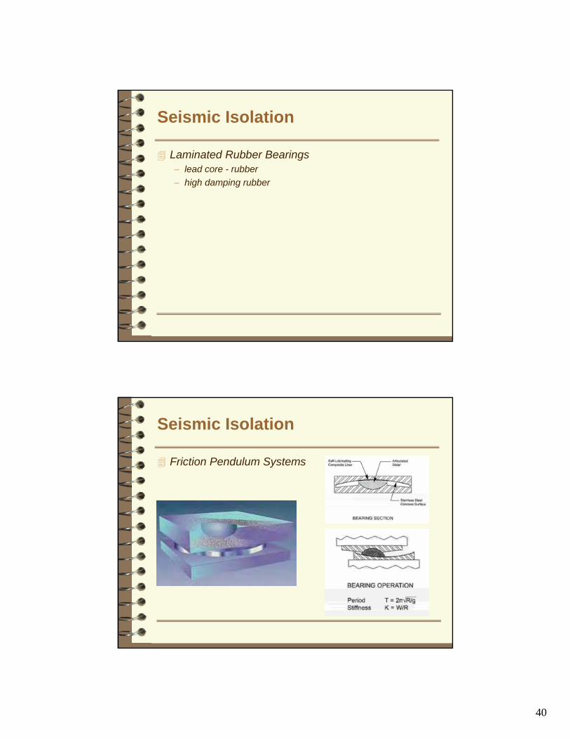
Seismic Isolation
Laminated Rubber Bearings– lead core - rubber– high damping rubber
Seismic Isolation
Friction Pendulum Systems
41
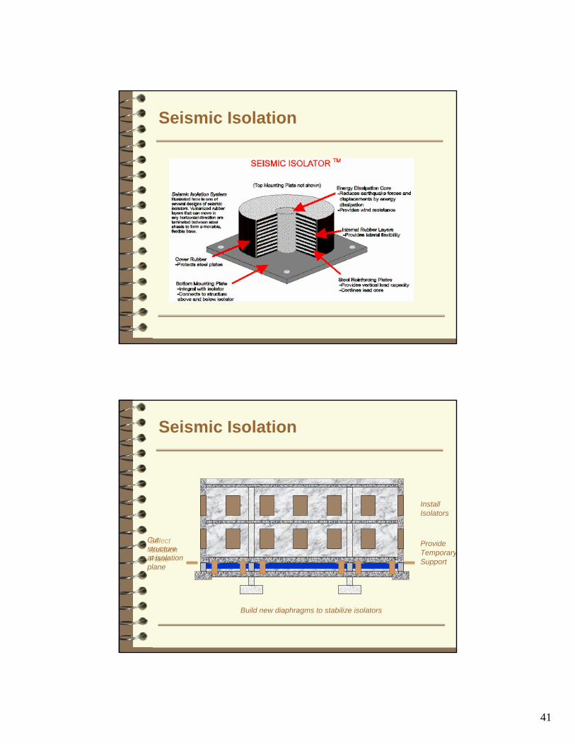
Seismic Isolation
Seismic Isolation
SelectIsolationPlane
Cutstructureat isolationplane
InstallIsolators
`
Build new diaphragms to stabilize isolators
`
ProvideTemporarySupport
42
Seismic Isolation
Expensive but highly effective technologyMost applicable to structures with period less than 1 sec.For structures with moderate strength has low impact on architecture of superstructureBest overall seismic performance
Methods of Enhancing Ductility
Removal (or replacement) of brittle componentsProviding shear heads at column slab interfacesRemoval of short column conditionsProvision of external reinforcement (Jacketing)
43
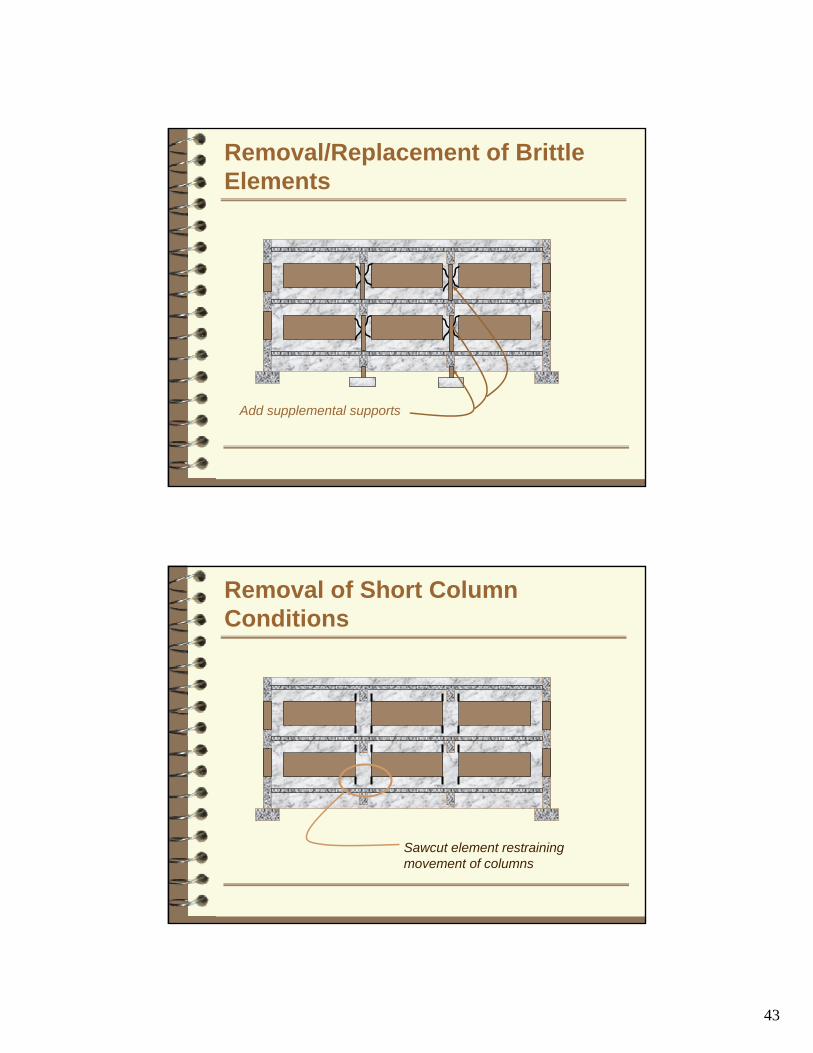
Removal/Replacement of Brittle Elements
Add supplemental supports
Removal of Short Column Conditions
Sawcut element restrainingmovement of columns

44
Composite Fabrics
Serve same purpose as reinforcing, except on exterior rather than interior of elementsCommon retrofit applications– Supplemental shear reinforcing in walls– Supplemental shear attachment of precast
elements– Confinement jacketing
Composite Fabrics
Material comes in sheets - like wall paperfibers aligned with sheettension strength provided only in fiber direction
Carbon or Glass fibers emedded in epoxy resin matrixGlass fiber subject to chemical attach from concreteEpoxy resins photo sensitive

45
Composite Fabrics
Advantages– economical– applies easily– minimal architectural
impact
Disadvantages– potential for degradation– limited applications
Supplemental Wall Reinforcing
Material applies in sheets (like wall paper)Reinforcing fibers are aligned along sheetSheets must be placed in orthogonal directions to simulate reinforcing
• Surface preparationand bonding critical
• Over-reinforcement possible

46
Supplemental Attachment
Confinement
Jacketing must completely and continuously encase elements, to form hoops of reinforcementMost effective on round membersRectangular corners must be rounded

47
Summary
Many (most?) concrete structures constructed prior to mid-1970s at significant riskMany techniques are available to improve these structuresUpgrades usually consist of– modifying response of structure to reduce deformation
induced by earthquake• strengthening and stiffening• adding damping• isolation (period shift)
– providing additional ductility for existing members to accommodate deformation