Reinforced Concrete Nominal Moment Calculator – A …One of the primary objectives of an...
14
Reinforced Concrete Nominal Moment Calculator – A Computer tool for Civil Engineering Students Abstract One of the primary objectives of an undergraduate reinforced concrete design course is to learn how to calculate the nominal moment capacity of reinforced concrete beams. This is traditionally accomplished by using basic mechanics, ultimate strength design principles and the Whitney stress block concept. Often this is overwhelming to students due to the plethora of variables in the ACI 2 code, the composite nature of reinforced concrete and the time it takes for new complex concepts to sink in. For this reason, in addition to classroom examples and homework, it is helpful to have a computer tool to assist in the learning process. Toward this end a computer program (Nominal Moment Calculator) with graphical user interface has been created. The Nominal Moment Calculator allows for up to 100 separate layers of steel (tensile or compressive), both rectangular and T-beams, user defined material properties, a graphical representation of the depth to neutral axis, c, and a descriptive output of calculations. Theory, program capabilities, sample classroom assignments, benefits toward ABET 1 objectives and results in the classroom due to use of the Nominal Moment Calculator are discussed. 1 Introduction Reinforced concrete design is perhaps one of the most challenging design courses undergraduate Civil engineering students must take. This is probably due to the composite nature of reinforced concrete and the seemingly endless barrage of ACI 2 variables used. More specifically, students often get overwhelmed with the mechanics of the Whitney stress block concept and strain compatibility for calculating the nominal moment capacity of reinforced concrete beams. The problem is further exacerbated when compression reinforcement, T-beams and multiple layers of steel are considered. Any strategies that foster student interest and comprehension are useful. The usual lectures, homework assignments and computation labs are appropriate, but it seems worthwhile to supplement these traditional methods with a computer program which can quickly provide results and verification. Students can also gain more experience by being able to modify computer input and quickly see the resulting effects on the output. With the above in mind, a computer program, called Nominal Moment Calculator, which is consistent with ACI 318-08 2 , has been created. In the following sections theory behind the computer program, design of the graphical user interface, sample output, sample assignments, student benefits, ABET 1 objectives addressed and conclusions are provided. 2 Theory behind Nominal Moment Calculator 2.1 General nominal moment strength by strain compatibility
Transcript of Reinforced Concrete Nominal Moment Calculator – A …One of the primary objectives of an...

Reinforced Concrete Nominal Moment Calculator –
A Computer tool for Civil Engineering Students
Abstract
One of the primary objectives of an undergraduate reinforced concrete design course is to learn
how to calculate the nominal moment capacity of reinforced concrete beams. This is traditionally
accomplished by using basic mechanics, ultimate strength design principles and the Whitney
stress block concept. Often this is overwhelming to students due to the plethora of variables in
the ACI2 code, the composite nature of reinforced concrete and the time it takes for new complex
concepts to sink in. For this reason, in addition to classroom examples and homework, it is
helpful to have a computer tool to assist in the learning process. Toward this end a computer
program (Nominal Moment Calculator) with graphical user interface has been created. The
Nominal Moment Calculator allows for up to 100 separate layers of steel (tensile or
compressive), both rectangular and T-beams, user defined material properties, a graphical
representation of the depth to neutral axis, c, and a descriptive output of calculations. Theory,
program capabilities, sample classroom assignments, benefits toward ABET1 objectives and
results in the classroom due to use of the Nominal Moment Calculator are discussed.
1 Introduction
Reinforced concrete design is perhaps one of the most challenging design courses undergraduate
Civil engineering students must take. This is probably due to the composite nature of reinforced
concrete and the seemingly endless barrage of ACI2 variables used. More specifically, students
often get overwhelmed with the mechanics of the Whitney stress block concept and strain
compatibility for calculating the nominal moment capacity of reinforced concrete beams. The
problem is further exacerbated when compression reinforcement, T-beams and multiple layers of
steel are considered. Any strategies that foster student interest and comprehension are useful.
The usual lectures, homework assignments and computation labs are appropriate, but it seems
worthwhile to supplement these traditional methods with a computer program which can quickly
provide results and verification. Students can also gain more experience by being able to modify
computer input and quickly see the resulting effects on the output. With the above in mind, a
computer program, called Nominal Moment Calculator, which is consistent with ACI 318-082,
has been created.
In the following sections theory behind the computer program, design of the graphical user
interface, sample output, sample assignments, student benefits, ABET1 objectives addressed and
conclusions are provided.
2 Theory behind Nominal Moment Calculator
2.1 General nominal moment strength by strain compatibility

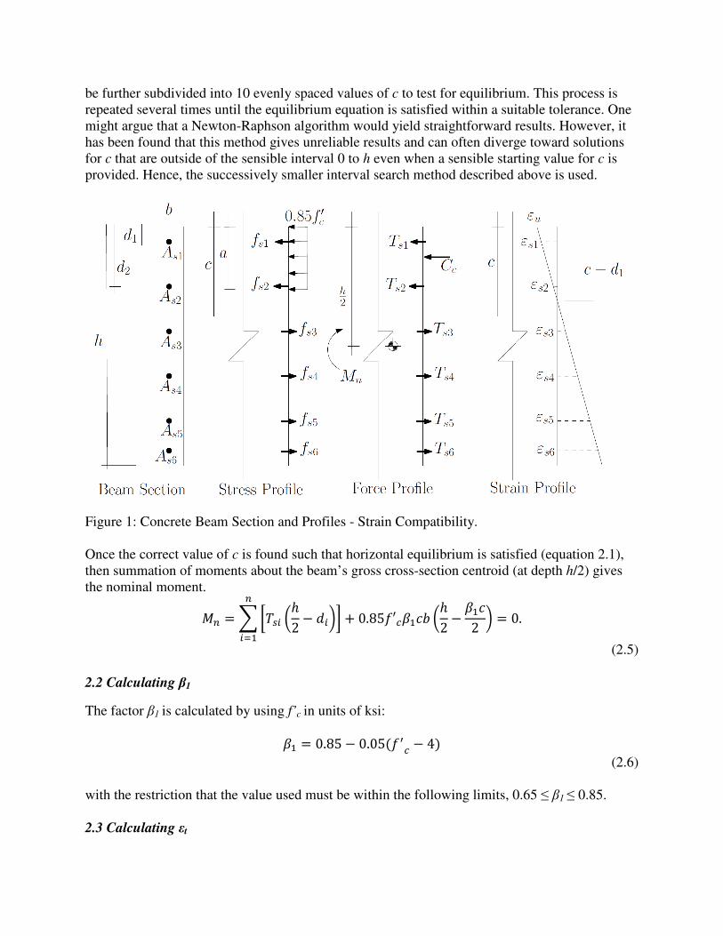
For brevity, only the development of the theory for rectangular beams is presented herein. The
case of T-beams follows from similar arguments and little modification.
Consider a rectangular beam with n-layers of steel as shown in Figure 1. In the Force Profile of
the figure the steel force, Tsi, at layer i is calculated based on an algorithm given below.
According to the Whitney stress block concept (see Nilson et al4 for more) the concrete
compressive force, Cc, is calculated as the Whitney stress, 0.85 f’c, times the area, ab = β1cb,
over which it acts. Note that if a steel bar is in the compression zone, the concrete not present
due to the presence of the steel bar is accounted for below in the algorithm for Tsi.
In Figure 1 an arbitrary distance to the neutral axis, c, is shown. The ensuing formulas are written
in terms of this unknown distance c. Horizontal force equilibrium is satisfied when the correct
value of c is used. Summing forces in the horizontal direction and choosing positive forces to the
left as shown in the Force Profile of Figure 1 yields the following:
���� + �� = ���� + 0.85 ′����� = 0,�
���
�
���
(2.1)
where force in a steel bar at layer i is Tsi (negative in tension and positive in compression due to
the formula for strain given below). The Tsi values are found by using the following algorithm:
(i) Determine the strain in bar i
��� = �� − ��� � ��,
where εu= 0.003 is the ultimate concrete strain specified by code.
(2.2)
(ii) Determine the stress in the steel bar at layer i
�� = ����� (2.3)
where the following restrictions apply to fsi in the following order given.
(a) Check if steel stress exceeds yield. If | fsi | > fy then fsi = (fsi /| fsi |) fy.
(b) Check if steel is in compression, if so; adjust for concrete not present at the steel
layer. If fsi > 0 then fsi = fsi −0.85 f’c.
(iii) Finally, the value of Tsi is calculated based on the above results.
��� = ����� (2.4)
The correct value of c will be between 0 and h. For example, it is straightforward to test 10
evenly spaced values of c in the interval 0 to h. The increment that bounds the best value of c can
be further subdivided into 10 evenly spaced values of c to test for equilibrium. This process is
repeated several times until the equilibrium equation is satisfied within a suitable tolerance. One
might argue that a Newton-Raphson algorithm would yield straightforward results. However, it
has been found that this method gives unreliable results and can often diverge toward solutions
for c that are outside of the sensible interval 0 to h even when a sensible starting value for c is
provided. Hence, the successively smaller interval search method described above is used.
Figure 1: Concrete Beam Section and Profiles - Strain Compatibility.
Once the correct value of c is found such that horizontal equilibrium is satisfied (equation 2.1),
then summation of moments about the beam’s gross cross-section centroid (at depth h/2) gives
the nominal moment.
�� = ����� �ℎ2 − ��"� + 0.85 ′����� �ℎ2 −���2 " = 0.
�
���
(2.5)
2.2 Calculating β1
The factor β1 is calculated by using f’c in units of ksi:
�� = 0.85 − 0.05( $� − 4) (2.6)
with the restriction that the value used must be within the following limits, 0.65 ≤ β1 ≤ 0.85.
2.3 Calculating εt

The maximum tensile strain in the steel is calculated as
�' = �()* − �� ��.
(2.7)
2.4 Calculating ϕ
The nominal resistance factor for beam bending is calculated as
+ = 0.483 + 83.3�'. (2.8)
with the restriction that the value used must be within the following limits, 0.65 ≤ ϕ ≤ 0.9. For εt
≥ 0.005 the value of ϕ is 0.9. With the ϕ factor in hand one can then calculate the nominal
factored moment, ϕMn, required by code and compare it to the factored moment caused by the
applied loads.
Figure 2: Main screen of Nominal Moment Calculator application.
3 Input and design of the graphical user interface
The graphical user interface (GUI) has been designed as simply as possible to be self
explanatory. The GUI has a typical menu bar but with only three menu items, File, Input and
Help (see Figure 2).
3.1 File
The File menu contains the typical options of Open, Save, Save As and Exit. The output and
input files are in a simple editable text file format. This is deliberate so that an input file with
many layers of steel could be computer generated and loaded into the Nominal Moment
Calculator without having to type in all the data.
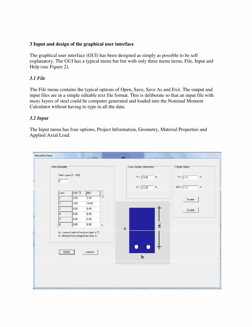
3.2 Input
The Input menu has four options, Project Information, Geometry, Material Properties and
Applied Axial Load.

Figure 3: Geometry input screen of Nominal Moment Calculator application.
3.2.1 Project Information
In the Project Information option the user may input the following fields: project title, job
number, beam description and designed by.
3.2.2 Geometry
For Geometry the user can select number of layers of steel, the total steel area for each layer i
and the depth di from the compression face to layer i. For rectangular beams the user can input
the beam width b and beam height h. When the T-beam option is enabled the user can also input
the T-beam flange thickness hf and the effective width beff . The Geometry input screen is shown
in Figure 3.
3.2.3 Material Properties
The user may enter the steel properties of modulus of elasticity, Es, and yield stress, fy. The
default values are 29,000 ksi and 60 ksi respectively. The user may also enter the concrete
properties of ultimate compressive stress, f’c and ultimate compressive strain, εu. The default
values are 3 ksi and 0.003.
3.2.4 Applied Axial Load
For rectangular beams only, the program does allow the user to input an axial load applied at the
beam’s gross cross section centroid. This option is not available for T-beams. The axial load
option is beneficial for a nominal moment calculation of a shear wall with axial and moment
loads applied to the cross-section. The default axial load is 0.0 kips.
3.3 Help
The help menu item contains the three options of Help, Disclaimer and About. The Help option
is a brief scroll bar with help text describing the program input. A Disclaimer is provided to
avoid liability for improper use of the program. Version information is provided in the About
option.
3.4 Calculations and Graphical Output To Screen
Two forms of output are provided on the main screen of the application (see Figure 2). First, a
text field is provided which shows detailed information about the calculations and final results
for ϕMn. The text field is automatically updated when any input item is changed. Output
calculations can be selected (highlighted) and saved to clipboard or sent to a printer. Second, a
graphical representation of the beam cross-section is drawn on the screen. The steel bars and
their location are shown. The concrete of the cross-section in compression is depicted by shading
on the cross-section down to the neutral axis c. This graphical representation can be sent to
printer also.

4 Sample output
To demonstrate use of the program and the resulting output, several examples are provided. A
rectangular beam with two layers of steel and a T-beam are given as examples.
4.1 Example 1 - Rectangular Beam
A rectangular beam is given with the following information, h=18 inches, b=12 inches, n=2
layers of steel, As1 = 2 in2, d1 = 2 inches, As2 = 2 in
2, d2 = 15 inches, f’c = 3 ksi, fy = 60 ksi. The
main screen and the geometry input pages for this case are shown in Figures 2 and 3. The results
indicate that the top layer of steel is in the compression zone and has not yet yielded. This
problem, if done by hand, would likely require several tedious iterations to find the correct value
of c. The output of calculations is given below.
Project Title: Example 1
Job #: 1
Beam Description: Example reinforced concrete beam with two layers of steel
Designed By: L. L. Yaw
Code Used: ACI 318-08
**********************
**** User Input ****
**********************
eu = 0.0030 in/in
fc = 3.000 ksi
fy = 60.000 ksi
Es = 29000.000 ksi
Pu = 0.000 kips
n = 2 layers of steel
Steel Area and Location From Compression Face
Layer# As(inˆ2) d(in)
1 2.00 2.00
2 2.00 15.00
Cross-Section Dimensions
b = 12.00 inches
h = 18.00 inches
***********************
***Output of Results***
***********************
** Analysis Type = Rectangular Beam **
Beta1 = 0.85, Alpha1 = 0.85
***Start Force Summary***
Steel Reinforcement Results At Each Layer
Layer# As(inˆ2) d(in) Ts(kip) es(in/in)
1 2.00 2.000 -51.32 -0.00088
2 2.00 15.000 120.00 0.01286
Maximum Steel Tensile Strain
et = 0.01286 in/in
The Concrete Compressive Force (reduced for any compression steel)
Cf = 68.68 kips
The Applied Axial Force
Pu = 0.00 kips
***End Force Summary***
Distance From Compression Face to Neutral Axis
c = 2.837 in
**Nominal Moment Strength**
Mn = 1618.61 kip-in
Mn = 134.88 kip-ft
***************************
** Phi Mn **
***************************
Phi = 0.900
PhiMn = 1456.75 kip-in
PhiMn = 121.40 kip-ft
***************************
***************************
*******End of Output*******
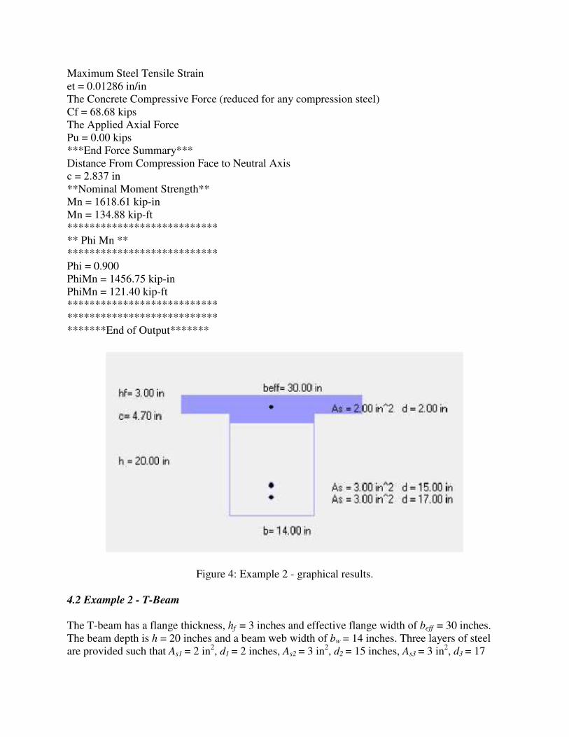
Figure 4: Example 2 - graphical results.
4.2 Example 2 - T-Beam
The T-beam has a flange thickness, hf = 3 inches and effective flange width of beff = 30 inches.
The beam depth is h = 20 inches and a beam web width of bw = 14 inches. Three layers of steel
are provided such that As1 = 2 in2, d1 = 2 inches, As2 = 3 in
2, d2 = 15 inches, As3 = 3 in
2, d3 = 17

inches. The material properties are f’c = 3 ksi and εu = 0.003 for concrete and fy = 60 ksi for steel.
The calculated output is given below. The graphical output for this case is shown in Figure 4
Project Title: Example 1
Job #: 1
Beam Description: Example reinforced concrete beam with two layers of steel
Designed By: L. L. Yaw
Code Used: ACI 318-08
**********************
**** User Input ****
**********************
eu = 0.0030 in/in
fc = 3.000 ksi
fy = 60.000 ksi
Es = 29000.000 ksi
Pu = 0.000 kips
n = 3 layers of steel
Steel Area and Location From Compression Face
Layer# As(inˆ2) d(in)
1 2.00 2.00
2 3.00 15.00
3 3.00 17.00
Cross-Section Dimensions
b = 14.00 inches
h = 20.00 inches
hf = 3.00 inches
beff = 30.00 inches
***********************
***Output of Results***
***********************
** Analysis Type = T-Beam **
Beta1 = 0.85, Alpha1 = 0.85
***Start Force Summary***
Steel Reinforcement Results At Each Layer
Layer# As(inˆ2) d(in) Ts(kip) es(in/in)
1 2.00 2.000 -100.00 -0.00172
2 3.00 15.000 180.00 0.00657
3 3.00 17.000 180.00 0.00785
Maximum Steel Tensile Strain
et = 0.00785 in/in
The Overhanging Beam Flanges Concrete Compressive Force
Ff = 122.40 kips
The Beam Web Concrete Compressive Force (reduced for any compression steel)
Cf = 137.60 kips
The Applied Axial Force
Pu = 0.00 kips

***End Force Summary***
Distance From Compression Face to Neutral Axis
c = 4.703 in
**Nominal Moment Strength**
Mn = 5101.40 kip-in
Mn = 425.12 kip-ft
***************************
** Phi Mn **
***************************
Phi = 0.900
PhiMn = 4591.26 kip-in
PhiMn = 382.60 kip-ft
***************************
***************************
*******End of Output*******
5 Sample assignments
Several example assignments are provided that make use of the Nominal Moment Calculator.
These assignments are easily integrated into a typical course in reinforced concrete design.
5.1 Assignment # 1
(a) Students are assigned regular reinforced concrete beam problems in which they are
required to find ϕMn by hand.
(b) Students are required to use the Nominal Moment Calculator to verify their results of part
(a). If they find differences in results they need to verify that they have entered all of the
correct information and/or they need to go back to their hand calculations and find what
they did incorrectly.
5.2 Assignment # 2
(a) Consider the following given beam. The beam has a depth h = 18 inches and a beam
width of b = 9 inches. One layer of steel is provided such that As1 = 2 in2, d1 = 15 inches.
The material properties are f’c = 3 ksi and εu = 0.003 for concrete and fy = 60 ksi for steel.
Input the information for the given beam into the Nominal Moment Calculator. What are
the results for ϕMn, c, εt and ϕ?
(b) Change the concrete strength for the beam of part (a) to f’c = 5 ksi. How does c change?
Why?
(c) Change area of steel for the beam of part (a) to As1 = 4 in2. How does c change? Why?
(d) Change area of steel for the beam of part (a) to As1 = 12 in2. What happens to εt? Why?
What happens to ϕ? Why?
5.3 Assignment # 3
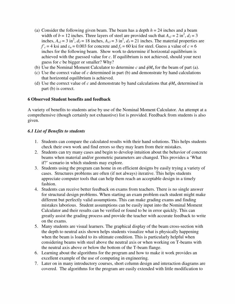
(a) Consider the following given beam. The beam has a depth h = 24 inches and a beam
width of b = 12 inches. Three layers of steel are provided such that As1 = 2 in2, d1 = 3
inches, As2 = 3 in2, d2 = 18 inches, As3 = 3 in
2, d3 = 21 inches. The material properties are
f’c = 4 ksi and εu = 0.003 for concrete and fy = 60 ksi for steel. Guess a value of c = 6
inches for the following beam. Show work to determine if horizontal equilibrium is
achieved with the guessed value for c. If equilibrium is not achieved, should your next
guess for c be bigger or smaller? Why?
(b) Use the Nominal Moment Calculator to determine c and ϕMn for the beam of part (a).
(c) Use the correct value of c determined in part (b) and demonstrate by hand calculations
that horizontal equilibrium is achieved.
(d) Use the correct value of c and demonstrate by hand calculations that ϕMn determined in
part (b) is correct.
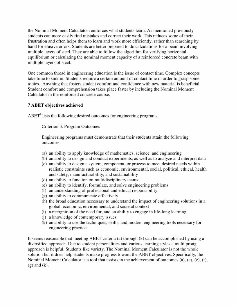
6 Observed Student benefits and feedback
A variety of benefits to students arise by use of the Nominal Moment Calculator. An attempt at a
comprehensive (though certainly not exhaustive) list is provided. Feedback from students is also
given.
6.1 List of Benefits to students
1. Students can compare the calculated results with their hand solutions. This helps students
check their own work and find errors so they may learn from their mistakes.
2. Students can try many cases and begin to develop intuition about the behavior of concrete
beams when material and/or geometric parameters are changed. This provides a ‘What
if?’ scenario in which students may explore.
3. Students using the program can home in on efficient designs by easily trying a variety of
cases. Structures problems are often (if not always) iterative. This helps students
appreciate computer tools that can help them reach an acceptable design in a timely
fashion.
4. Students can receive better feedback on exams from teachers. There is no single answer
for structural design problems. When starting an exam problem each student might make
different but perfectly valid assumptions. This can make grading exams and finding
mistakes laborious. Student assumptions can be easily input into the Nominal Moment
Calculator and their results can be verified or found to be in error quickly. This can
greatly assist the grading process and provide the teacher with accurate feedback to write
on the exams.
5. Many students are visual learners. The graphical display of the beam cross-section with
the depth to neutral axis shown helps students visualize what is physically happening
when the beam is loaded to its ultimate condition. This is particularly helpful when
considering beams with steel above the neutral axis or when working on T-beams with
the neutral axis above or below the bottom of the T-beam flange.
6. Learning about the algorithms for the program and how to make it work provides an
excellent example of the use of computing in engineering.
7. Later on in many introductory courses, short column design and interaction diagrams are
covered. The algorithms for the program are easily extended with little modification to

allow computation of points on a column interaction diagram. Hence, the information
learned by using the nominal moment calculator is a precursor to future topics. Students
can with adequate guidance write their own algorithms to construct concrete column
interaction diagrams.
8. Using computers for learning exercises appeals to many students.
9. Computers are often used in professional practice. The Nominal Moment Calculator
provides an input page as mentioned previously where students may enter project title,
job number, beam description and designed by. These items are a small but simple
introduction of how real world professionals document their work. Every form of
professionalism that can be instilled in students during the course of their education will
be beneficial to them.
10. Shear walls in flexure require the calculation of their nominal moment. Rectangular walls
can be easily treated as rectangular beams with multiple layers of steel. When shear walls
have a thicker boundary element than the rest of the wall, the T-beam option may be used
with multiple layers of steel.
11. The nominal moment capacity of masonry beams or shear walls can be calculated. The
Nominal Moment Calculator allows the user to alter the ultimate compressive strain
specified for the materials being used. Per MSJC3 section 3.3.2(c) the maximum usable
strain εmu is assumed to be 0.0035 for clay masonry and 0.0025 for concrete masonry.
Hence, the Nominal Moment Calculator prepares the way to introduce design of masonry
flexural elements and how they are designed differently than concrete.
12. Undergraduate students are better prepared for graduate school. The extension of the
Whitney stress block concept and strain compatibility for a singly reinforced concrete
beam to the general case of n layers of steel is beneficial to a student’s development.
Many concepts in graduate school are general extensions of simpler cases covered in
undergraduate courses. Developing this kind of thinking in students early on helps them
think toward the ‘next’ step. It leads to thinking that allows them to confront more
difficult problems.
6.2 Student Feedback
Student feedback has been very positive since the program was included in the reinforced
concrete course. Students really appreciate the ability to verify their own work and, if they find a
mistake, discover on their own what they did incorrectly. The user interface is consistently
described as ‘very easy to use’. The graphical display is based on input and students have
realized dimensional input mistakes by looking at the graphical results. Many students
specifically note that the graphical display helps them better visualize and internalize the
concepts involved in nominal moment calculations. This is very appealing to them instead of just
looking at equations. Students enjoy being able to change variables and immediately see the
results. This helps them develop better understanding and intuition about how reinforced
concrete beams function. Students recognize the benefits from using the application.
6.3 Observed Results in the Classroom
The Nominal Moment Calculator is a beneficial supplement for students. Clearly, the traditional
class room lectures and hand calculation exercises are still needed in the course. However, using
the Nominal Moment Calculator reinforces what students learn. As mentioned previously
students can more easily find mistakes and correct their work. This reduces some of their
frustration and often helps them to learn and work more efficiently, rather than searching by
hand for elusive errors. Students are better prepared to do calculations for a beam involving
multiple layers of steel. They are able to follow the algorithm for verifying horizontal
equilibrium or calculating the nominal moment capacity of a reinforced concrete beam with
multiple layers of steel.
One common thread in engineering education is the issue of contact time. Complex concepts
take time to sink in. Students require a certain amount of contact time in order to grasp some
topics. Anything that fosters student comfort and confidence with new material is beneficial.
Student comfort and comprehension takes place faster by including the Nominal Moment
Calculator in the reinforced concrete course.
7 ABET objectives achieved
ABET1 lists the following desired outcomes for engineering programs.
Criterion 3. Program Outcomes
Engineering programs must demonstrate that their students attain the following
outcomes:
(a) an ability to apply knowledge of mathematics, science, and engineering
(b) an ability to design and conduct experiments, as well as to analyze and interpret data
(c) an ability to design a system, component, or process to meet desired needs within
realistic constraints such as economic, environmental, social, political, ethical, health
and safety, manufacturability, and sustainability
(d) an ability to function on multidisciplinary teams
(e) an ability to identify, formulate, and solve engineering problems
(f) an understanding of professional and ethical responsibility
(g) an ability to communicate effectively
(h) the broad education necessary to understand the impact of engineering solutions in a
global, economic, environmental, and societal context
(i) a recognition of the need for, and an ability to engage in life-long learning
(j) a knowledge of contemporary issues
(k) an ability to use the techniques, skills, and modern engineering tools necessary for
engineering practice.
It seems reasonable that meeting ABET criteria (a) through (k) can be accomplished by using a
diversified approach. Due to student personalities and various learning styles a multi prong
approach is helpful. Students like variety. The Nominal Moment Calculator is not the whole
solution but it does help students make progress toward the ABET objectives. Specifically, the
Nominal Moment Calculator is a tool that assists in the achievement of outcomes (a), (c), (e), (f),
(g) and (k).
8 Conclusion
A computer program for the calculation of the nominal moment capacity of reinforced concrete
beams is included in a standard undergraduate reinforced concrete design course. The intent is to
help students learn the concepts of reinforced concrete beam design better for the various cases
of rectangular beams, T-beams, compression reinforcement and multiple layers of steel. The
feedback from students, regarding the computer application, has been very positive. Students
really appreciate being able to check their hand calculations with the Nominal Moment
Calculator. The computer program, which supplements traditional lectures and homework
problems, also helps students make progress toward achieving ABET outcomes (a), (c), (e), (f),
(g) and (k). Many other benefits have also been identified. Learning is a multifaceted endeavor.
A diversified use of learning tools is helpful and appreciated by students when learning complex
concepts in the engineering curriculum.
The Nominal Moment Calculator (mnN.exe) can be downloaded from the following location:
http://people.wallawalla.edu/~louie.yaw/otherfiles/
References
1. ABET. CRITERIA FOR ACCREDITING ENGINEERING PROGRAMS - Effective for Evaluations During
the 2010-2011 Accreditation Cycle. ABET, Inc., Baltimore, Maryland, 2009.
2. ACI. ACI 318-08, Building Code Requirements for Structural Concrete and Commentary. American
Concrete Institute, Farmington Hills, Michigan, 2008.
3. MSJC. Masonry Standards Joint Committee (MSJC), Building Code Requirements and Specification for
Masonry Structures. The Masonry Society, Boulder, Co, 2008.
4. A. H. Nilson, D. Darwin, and C.W. Dolan. Design of Concrete Structures. McGraw-Hill, New York, NY,
14th edition, 2010.