Reinforced Brick-Masonry Light Vaults. Semi … · Reinforced Brick-Masonry Light Vaults....
21
1 Reinforced Brick-Masonry Light Vaults. Semi-Prefabrication, Construction, Testing and Numerical Modeling. F. López-Almansa a* , V. Sarrablo b , P.B. Lourenço c , J.A.O. Barros c , P. Roca d , F. da Porto e , C. Modena e a Architecture Structures Department, Technical University of Catalonia, Avda. Diagonal 649, 08028 Barcelona, Spain b Architecture Construction Department, International University of Catalonia, Immaculada 22, 08017 Barcelona, Spain c Civil Engineering Department, University of Minho, Guimarães 4800-058, Portugal d Construction Engineering Department, Technical University of Catalonia, C. Jordi Girona 1/3, 08034 Barcelona, Spain e Department of Structural and Transportation Engineering, University of Padova, via Marzolo 9, 35131 Padua, Italy Abstract This work deals with short to mid span-length light vaults made of reinforced brick-masonry. The research is oriented at proposing semi- prefabrication and construction techniques. Numerical models for predicting the structural behavior of this type of structures are developed. Experimental research is performed with the following three main objectives: (i) validating the proposed construction techniques, (ii) investigating the structural performance, and (iii) calibrating the numerical models. The obtained results show that the proposed techniques are feasible, and that the structural behavior is adequate in terms of ductility and of strength. The structural system can be modeled with the developed numerical tools. Keywords: vaulted roofs, light roofs, nonlinear structural analysis, damage models, semi-prefabrication, reinforced brick masonry, brick shells. 1 Introduction Historical and traditional construction has made use of bricks in arches, vaults and shells, leading to slender, light and ingenious solutions whose strength was mostly guaranteed by the curved shape like those built by the Spanish architect Rafael Guastavino (Huerta, 2003; Friedman 2008). The Uruguayan engineer Eladio Dieste (Anderson, 2004; Daguerre, 2003 and Pedreschi 2000) built a number of reinforced brick masonry vaults and double-curvature shells spanning up to 50 m with only about 120 mm thickness. In spite of the numerous architectural advantages and the sustainability of such clever technologies, nowadays are not widely used mainly due to the following reasons: The technology is labor demanding. It booms the cost, mainly for developed countries, and impairs the feasibility and reliability of these roofing solutions. The structural behavior is complex because of irregular shapes, the coexistence of several materials and the relevance of rheology and, in some cases, of buckling. Hence, there are no reliable and accurate numerical models. This hinders the comprehension of the mechanical and resisting principles, causes a lack of design guidelines and prevents the development of daring or innovative solutions. For creating imaginative and complex shapes, designers require powerful CAD tools. The major design codes, namely the Eurocodes and the NAs, do not consider these roofing technologies. The objective of the present research is to foster the use of reinforced brick masonry shells for vaulted light roofs. The strategy consists of overcoming each of the aforementioned limitations through the following developments: To propose semi-prefabrication and construction technologies for light-weight reinforced brick masonry vaults using light formworks and virtually no moulds. This includes the design of special-purpose bricks. This research is supported by extensive testing. One of the main concerns has been to lower the cost up to roughly those of competing techniques, mainly concrete and steel based. To develop a finite element code (called PRO-SHELL) to describe accurately the structural behavior of shell roofs. A simpler software (called DBS-ROOF) is also derived for daily use. These numerical tools are calibrated with experimental results obtained in the framework of the research. To derive software modeling tools for architectural design of vaulted roofs. The resulting software package is referred as ARCH-ROOF. This software is able to optimize the shape of the vault following structural criteria. ARCH-ROOF is easily connectable to PRO-SHELL and to DBS-ROOF, thus allowing integrated design and structural analysis. Design guidelines arising from this research might be incorporated in relevant codes. * Corresponding author. Tel.: + 34-93-4016316; FAX + 34-93-4016320; e-mail: [email protected]
Transcript of Reinforced Brick-Masonry Light Vaults. Semi … · Reinforced Brick-Masonry Light Vaults....
1
Reinforced Brick-Masonry Light Vaults. Semi-Prefabrication, Construction, Testing and Numerical Modeling.
F. López-Almansaa*
, V. Sarrablob, P.B. Lourençoc, J.A.O. Barrosc, P. Rocad, F. da Portoe, C. Modenae
a Architecture Structures Department, Technical University of Catalonia, Avda. Diagonal 649, 08028 Barcelona, Spain b Architecture Construction Department, International University of Catalonia, Immaculada 22, 08017 Barcelona, Spain
c Civil Engineering Department, University of Minho, Guimarães 4800-058, Portugal d Construction Engineering Department, Technical University of Catalonia, C. Jordi Girona 1/3, 08034 Barcelona, Spain
e Department of Structural and Transportation Engineering, University of Padova, via Marzolo 9, 35131 Padua, Italy
Abstract This work deals with short to mid span-length light vaults made of reinforced brick-masonry. The research is oriented at proposing semi-prefabrication and construction techniques. Numerical models for predicting the structural behavior of this type of structures are developed. Experimental research is performed with the following three main objectives: (i) validating the proposed construction techniques, (ii) investigating the structural performance, and (iii) calibrating the numerical models. The obtained results show that the proposed techniques are feasible, and that the structural behavior is adequate in terms of ductility and of strength. The structural system can be modeled with the developed numerical tools. Keywords: vaulted roofs, light roofs, nonlinear structural analysis, damage models, semi-prefabrication, reinforced brick masonry, brick shells.
1 Introduction Historical and traditional construction has made use of bricks in arches, vaults and shells, leading to slender, light and ingenious solutions whose strength was mostly guaranteed by the curved shape like those built by the Spanish architect Rafael Guastavino (Huerta, 2003; Friedman 2008). The Uruguayan engineer Eladio Dieste (Anderson, 2004; Daguerre, 2003 and Pedreschi 2000) built a number of reinforced brick masonry vaults and double-curvature shells spanning up to 50 m with only about 120 mm thickness. In spite of the numerous architectural advantages and the sustainability of such clever technologies, nowadays are not widely used mainly due to the following reasons: The technology is labor demanding. It booms the cost, mainly for developed countries, and impairs the feasibility and
reliability of these roofing solutions. The structural behavior is complex because of irregular shapes, the coexistence of several materials and the relevance of
rheology and, in some cases, of buckling. Hence, there are no reliable and accurate numerical models. This hinders the comprehension of the mechanical and resisting principles, causes a lack of design guidelines and prevents the development of daring or innovative solutions.
For creating imaginative and complex shapes, designers require powerful CAD tools. The major design codes, namely the Eurocodes and the NAs, do not consider these roofing technologies. The objective of the present research is to foster the use of reinforced brick masonry shells for vaulted light roofs. The strategy consists of overcoming each of the aforementioned limitations through the following developments: To propose semi-prefabrication and construction technologies for light-weight reinforced brick masonry vaults using light
formworks and virtually no moulds. This includes the design of special-purpose bricks. This research is supported by extensive testing. One of the main concerns has been to lower the cost up to roughly those of competing techniques, mainly concrete and steel based.
To develop a finite element code (called PRO-SHELL) to describe accurately the structural behavior of shell roofs. A simpler software (called DBS-ROOF) is also derived for daily use. These numerical tools are calibrated with experimental results obtained in the framework of the research.
To derive software modeling tools for architectural design of vaulted roofs. The resulting software package is referred as ARCH-ROOF. This software is able to optimize the shape of the vault following structural criteria. ARCH-ROOF is easily connectable to PRO-SHELL and to DBS-ROOF, thus allowing integrated design and structural analysis.
Design guidelines arising from this research might be incorporated in relevant codes.
* Corresponding author. Tel.: + 34-93-4016316; FAX + 34-93-4016320; e-mail: [email protected]

2
This paper concentrates mainly on the two first points above. These techniques refer exclusively to short to mid span vaults, i.e. up to about 12 m. This research belongs to a project funded by the European Commission (ISO-BRICK, 2004) aimed at promoting innovative semi-prefabrication and construction techniques for reinforced brick masonry vaults; partners belong mainly to Spain, Portugal and Italy. 2 Proposed vaults The vaults are mainly intended to cover rectangular spaces, as described in Figure 1 depicting a rectangular space split in parallel strips. Each strip is composed of one or several semi-prefabricated sheets; for instance, in Figure 1 each strip is composed of two sheets.
Figure 1. Vaulted roof
The main geometrical parameters of the vaults are denoted as follows (see Figure 1): L is the span length; nL is the number of parallel vaults (only a vault is shown in Figure 1); l is the width of each strip; nl is the number of strips per vault (nl = 12 in Figure 1); b is the roof length (b = nl × l), S is the arc-length of each sheet; nS is the number of sheets per strip (nS = 2 in Figure 1); F is the rise of the vault; t is the vault thickness. Table 1 shows the range values of these parameters. “Tested range” accounts for the values considered in the experiments while “Suggested range” refers to the recommended values for real applications; vaults exceeding these limits might require further testing.
(a) (b) (c)
Figure 2. Reinforced brick masonry vaults: (a) laboratory tests; (b,c) prototype built in Matera (Italy) (da Porto et al., 2005; Piaggio, 2005). Figure 2 shows three views of completed vaults. As shown in Figure 2(c), the aspect of the lower surface of the vault is an orthogonal network of fair-face bricks.
l
L
ELEVATION
PLAN VIEW
strip
sheets
vault
supports
b
t F
L
S

3
a Limited only by the prefabrication and transportation facilities b The upper bound depends mainly on L through structural and constructional issues
(a) (b)
Figure 3. Bricks: (a) type B2; (b) type B3 Special bricks were designed and fabricated. Figure 3 shows two solutions, termed B2 (Figure 3(a)) and B3 (Figure 3(b)). The upper faces of the bricks of Figure 3 are dove-tailed rugged to increase their bonding while the lower face is fair-face flat. Both bricks are 100 mm long, 240 mm wide and 45 mm deep; this size was chosen to allow easy handling and proper fitting inside the sheets and the vaults. The purpose of the side grooves is discussed in the next section. Next two sections present the suggested procedures to build wall or column-supported barrel vaults intended to cover a rectangular space like the one schematically represented in Figure 1. The proposed solution includes two consecutive phases: semi-prefabrication of flexible steel-brick sheets and on-site construction. 3 Semi-prefabrication The outputs of this phase are flexible yet monolithic steel-brick sheets; Figure 4 displays a pair of views of completed sheets.
Figure 4. Completed steel-brick sheets Figure 4 shows that the sheets are composed by a topping steel layer and a bottom layer consisting of bricks arranged with continuous joints –orthogonal pattern– in four rows and steel bars laying in some of these joints, thus forming the lower longitudinal reinforcement. The production of the sheets is composed of the following five consecutive steps: (i) laying of a thin glued film on flat boards, (ii) arrangement of the bricks and the lower longitudinal reinforcement bars on this layer, (iii) placement of the upper steel layer, (iv) mechanical connection between the upper and lower steel layers, and (v) transportation to the truck or to any temporary storage space. A description of these phases follows. Placement of the lower film. The process starts by laying the pre-glued film on the working boards with the purposes of guaranteeing immobility of bricks during their placement, serving as a temporary protective layer, preventing accidental brick falling, avoiding sliding of bricks during transportation and in steep surfaces during the construction phase, avoiding mortar leakage in the construction phase, and allowing ease demolding. To guarantee an even gluing of the bricks, a soft support layer might be placed under the film; conventional foam was used. Cleanliness, dryness and lower face geometrical regularity
Table 1. Range of the geometrical parameters
Geometrical parameter L (m) nL l (m) nl S (m) nS F (m) t (mm) Tested range 4 - 10 1 1 1 - 3 4.15 – 6.55 1 - 2 0.34 – 5.37 75 - 100
Suggested range 3 - 12 any # 1 any # 3.15 – a any # 0.30 – b 75 - 100
inner joints
outer joints

4
of bricks are crucial to this purpose. Laying of bricks and of the longitudinal lower reinforcement. Different alternative solutions were considered to guide the placement of bricks on the film; all of them used mechanical elements shaped like the desired network. The four rows of bricks are laid together with the longitudinal lower reinforcement following always the same order: (i) one row of bricks is laid; (ii) longitudinal reinforcement bar in the first joint is placed; (iii) the adjacent second row of bricks is laid; (iv) the next steel bars and rows of bricks are consecutively placed until completing the assembly. The grooves in the sides of the bricks (Figure 3) allow the insertion of mechanical elements intended to keep the lower longitudinal reinforcement bars in their desired positions. Two solutions are suggested for such elements: a series of short transversal bars welded to the main one as a kind of “fish-bone” (Figure 5) and special purpose mechanical fasteners (Figure 6).
Figure 5. Laid bricks with fish bone solution as longitudinal reinforcement
(a)
(b) (c)
Figure 6. Laid bricks with mechanical fasteners to fix the longitudinal reinforcement: (a) fasteners for brick B2; (b) fasteners for brick B3; (c) example of installed system with fasteners
Placement of the upper steel layer. Two possibilities have been considered as topping steel layer, namely an expanded metal sheet (see Figure 4) and a conventional welded mesh (see Figure 15). The second solution can play the role of top reinforcement but the resulting sheet can have difficulties on fitting highly curved shapes. Hence, the first alternative is generally recommended except for near-flat roofs. It should be kept on mind that the expanded metal does not contribute significantly to the strength of the vault (Oliveira et al. 2002). Connection between the upper and lower steel layers. This step consists of tying all the lower bars to the upper steel layer with steel wires. The result is a monolithic, movable and flexible film-bricks-steel assembly. Transportation. The produced sheets are conveyed flat by truck to the construction site. A conventional crane is used for transportation from the prefabrication tables to the truck or to stock, and from the truck to the final location. Two possibilities have been considered for these operations, see Figure 7: (a) to hang the sheet from hooks connected to its upper side and to
inner joints
outer joint
fish-bones
fasteners
5
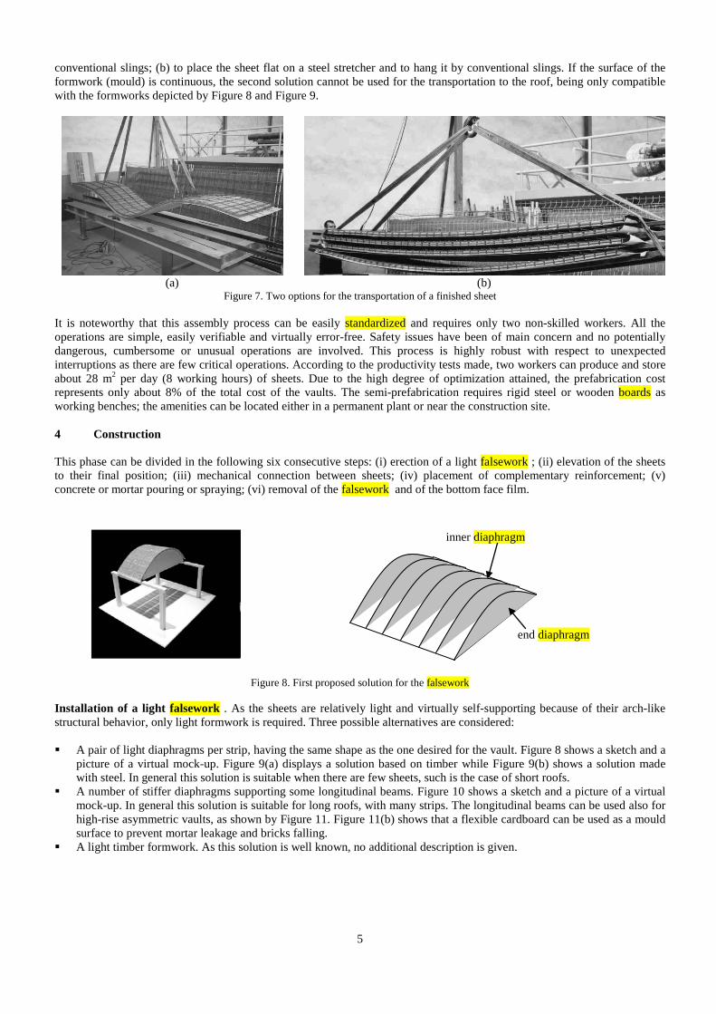
conventional slings; (b) to place the sheet flat on a steel stretcher and to hang it by conventional slings. If the surface of the formwork (mould) is continuous, the second solution cannot be used for the transportation to the roof, being only compatible with the formworks depicted by Figure 8 and Figure 9.
(a) (b)
Figure 7. Two options for the transportation of a finished sheet It is noteworthy that this assembly process can be easily standardized and requires only two non-skilled workers. All the operations are simple, easily verifiable and virtually error-free. Safety issues have been of main concern and no potentially dangerous, cumbersome or unusual operations are involved. This process is highly robust with respect to unexpected interruptions as there are few critical operations. According to the productivity tests made, two workers can produce and store about 28 m2 per day (8 working hours) of sheets. Due to the high degree of optimization attained, the prefabrication cost represents only about 8% of the total cost of the vaults. The semi-prefabrication requires rigid steel or wooden boards as working benches; the amenities can be located either in a permanent plant or near the construction site. 4 Construction This phase can be divided in the following six consecutive steps: (i) erection of a light falsework ; (ii) elevation of the sheets to their final position; (iii) mechanical connection between sheets; (iv) placement of complementary reinforcement; (v) concrete or mortar pouring or spraying; (vi) removal of the falsework and of the bottom face film.
Figure 8. First proposed solution for the falsework
Installation of a light falsework . As the sheets are relatively light and virtually self-supporting because of their arch-like structural behavior, only light formwork is required. Three possible alternatives are considered: A pair of light diaphragms per strip, having the same shape as the one desired for the vault. Figure 8 shows a sketch and a
picture of a virtual mock-up. Figure 9(a) displays a solution based on timber while Figure 9(b) shows a solution made with steel. In general this solution is suitable when there are few sheets, such is the case of short roofs.
A number of stiffer diaphragms supporting some longitudinal beams. Figure 10 shows a sketch and a picture of a virtual mock-up. In general this solution is suitable for long roofs, with many strips. The longitudinal beams can be used also for high-rise asymmetric vaults, as shown by Figure 11. Figure 11(b) shows that a flexible cardboard can be used as a mould surface to prevent mortar leakage and bricks falling.
A light timber formwork. As this solution is well known, no additional description is given.
inner diaphragm
end diaphragm

6
(a)
(b)
Figure 9. Timber board and steel falseworks (first solution)
Figure 10. Second proposed solution for the falsework Elevation of the sheets to their final position. The sheets are elevated by a crane with slings connected to them by any of the two possibilities described in Figure 7. In steep locations, a kind of “hooked tilting” transportation will be used. Figure 12 displays consecutively, from left to right, such process for the formwork depicted by Figure 11. Mechanical connection among sheets. Once the sheets are placed in their final position, should be tied together by proper mechanical devices. Two types of connections exist: transversal, i.e. among adjacent parallel sheets, and longitudinal, i.e. among following sheets. Only the longitudinal connections dealing with the lower reinforcement are described in this step; those dealing with the upper reinforcement, as well as the transversal connections are discussed in the next step. For the mechanical connections among the lower longitudinal reinforcement bars, two general procedures are foreseen: overlapping and welding. Welding has some disadvantages since it is expensive and requires skilled workers, especial devices and power supply. However, in highly or even moderately curved surfaces it constitutes the only reliable mean to link the two adjoining sheets because the overlapping is not feasible due to the difficulties of introducing the connecting bars in the curved joints among neighboring bricks.
(a) (b) (c)
Figure 11. Example of formwork. Second solution
brick-steel strip j i
longitudinal beam j i
end diaphragm j i

7
Figure 12. Placement of sheets on the falsework Placement of complementary reinforcement. Two additional reinforcements are still required: Transversal lower reinforcement bars, with the purposes of providing resistance for transversal bending and of
guaranteeing evenness among adjacent sheets. Such bars lay along the joints between bricks; normally a bar every three or more joints would be sufficient.
Upper reinforcement made of conventional welded steel mesh. This reinforcement is needed only if expanded metal sheet has been used in the semi-prefabrication phase. The structural continuity will be guaranteed by overlapping of the adjacent meshes, as it is usually done in conventional continuous laminar structures of reinforced concrete.
Additionally, bars can be placed in the joints among adjacent sheets to provide further longitudinal flexural strength and stiffness (Figure 13).
Figure 13. Joint between adjacent sheets with 12 mm re-bar Concreting. The construction can be completed from the extrados with a concrete or mortar pouring or spraying. The main requirements of such material are: Compressive strength higher than about 5 MPa. Proper penetration. Relevant to obtain an even and aesthetic appearance of the intrados and to provide the re-bars with
enough protection against corrosion and with good bond properties. Only shallow penetration inside the holes of the bricks to avoid excessive self weight. Small segregation in steep surfaces. The first requirement is mostly related to the mix design requirements, namely water/cement ratio and binder strength and content. The other requirements deal mostly with the concrete slump, which can be optimized using proper water content, additives and superplasticizers (Barros et al. 2003). The penetrability depends also on the maximum aggregate size; a diameter up to 1/5 of the recess to be filled can be used. To avoid excessive concrete penetration into the bricks’ holes, their extremities can be blocked by any material of low cost and easy application.
mortar bed
12 mm re-bar j i
8 mm re-bar j i
separator j i

8
(a) (b) (c) (d) (e)
Figure 14. First solution for concreting (No Pressure). Conventional (gravity) concreting
(a) (b) (c)
Figure 15. Second solution for concreting (Low Pressure). Forced (spraying) concreting
(a) (b) (c)
Figure 16. Third solution for concreting (High Pressure). Sprayed mortar Three possibilities are considered for the concreting of the vaults: (a) Conventional gravity pouring as shown in Figure 14; (b) Mortar sprayed by a low pressure pump with a thin nozzle, as shown in Figure 15; and (c) Concrete sprayed by a high pressure pump with a thick nozzle, as shown in Figure 16. In case of the first possibility, fluid mortar (using superplasticizers) can be used to fill the joints, while conventional mortar or concrete can be applied for the topping layer. Manual compaction is required to guarantee proper filling of the joints. In the vaults built at Spain the mortar is composed of a part of cement, three parts of aggregate and half part of water. A 2 mm maximum aggregate size was used. In the vaults built at Italy two different premixed mortars were used to fill the joints and to form the top layer. Both are hydraulic lime based mortars with rheoplastic properties and a 4 mm maximum aggregate size. Additives were used only in the concrete for the joints. The characteristics of the mix composition of the vault built in Portugal can be found in (Barros et al. 2003). In the second possibility for concreting, two types of mortar have been used: “high strength” with about 30 MPa of compressive strength, developed specifically for this purpose, and conventional sprayable mid strength mortar, used normally for inner walls lining and with about 16 MPa of

9
compressive strength. Finally, the third possibility for concreting is based on a concrete that is usually utilized for swimming pools and similar retaining walls, where a 3 mm maximum aggregate size was used. For any solution, the formwork could be vibrated. The outer surface can be evened by a conventional screed as shown in Figure 14(e) and in Figure 16(c). The second concreting possibility is significantly more expensive than the other ones due to the high cost of the mortar and of the spraying pump; moreover, the personnel has to be qualified. The first concreting solution is slower but can be speed up using more workers; this is not possible in the second solution unless more pumps are used. The third concreting possibility is significantly faster. Removal of the film and of the falsework. After the concrete or mortar hardening, the lower plastic film layer can be manually removed and, in general, no further cleaning or other operations of the underside are required. Figure 17(a) shows a view of this operation and the obtained result is visible in Figure 17(b). One of the key issues in this step is to avoid remains of glue in the outer surface of the bricks, meaning that too strong glue has to be avoided. The proper aesthetic appearance of the intrados is of the major importance as the aesthetics is the most appealing advantage of these roofing techniques.
(a) (b)
Figure 17. Film removal 5 Testing 5.1 Global description A number of tests have been carried out; their main objectives are: Designing and validating the proposed semi-prefabrication and construction technologies. Noticeably, such validation has
to include normal (rough) operation conditions. Assessing the local and global structural performance of the vaults. The main issues to be investigated are the collapse
loads, the most expectable failure modes, the ductility, the creep behavior, the stiffness, the natural frequencies and the punching shear strength.
Calibrating the developed numerical models. To include as much as relevant situations as possible, besides the span-rise and shape of the vault, additional analyzed issues are: (1) instantaneous or sustained load, (2) applied force or prescribed displacement, (3) slab-like or shell-like behavior (bending or combined membrane-bending action), (4) hinged, clamped or elastic sliding ends, (5) individual or coupled behavior with other structural elements, and (6) high or low strength mortar.
The tests are designed according to these objectives yet accounting for time, budget and space constraints. The experiments can be broadly divided in three groups: (1) materials (2) small specimens of vaults and (3) full-scale vaults. Loading tests of similar vaults built by traditional techniques were carried out previously (Sarrablo, 2002), being the results similar to those described in this paper. Nevertheless, the preliminary results provided evidence of adequate structural performance of the vaults and of the possibility of simulating it with simple numerical models. 5.2 Tests carried out in Portugal: Materials and small specimens The tests carried out at the Structural Laboratory of the Civil Engineering Department, University of Minho, can be categorized in two groups, namely, material tests and structural tests with prototypes. The first group of tests had the purpose of assessing the properties of the materials constituting the developed reinforced masonry shell system, namely: (i) direct tension and compression behavior of brick units; (ii) direct compression behavior of mortar and concrete; (iii) bond between brick and mortar; (iv) tensile behavior of expanded metal sheet, steel wire meshes and steel bars. The structural tests with prototypes had the purpose of assessing the performance of the structural system when submitted to: (i) in-plane shear with

10
distinct levels of lateral confinement; (ii) out-of-plane loading with flexural failure mode; (iii) out-of-plane loading with shear failure load. Figure 18(a) presents the test set-up used to evaluate the compression Young’s Modulus of the adopted bricks. The test set-up shown in Figure 18(b) was used to evaluate the direct tensile behavior of brick specimens. The typical failure mode is represented in Figure 18(c). From the typical tensile stress vs. displacement, included in Figure 19, the tensile strength was obtained, together with the stress-crack opening relationship and the fracture energy. Detailed information about these tests can be found elsewhere (Lourenço et al. 2005). To assess the brick-concrete bond performance, uniaxial tensile tests were carried out according to the test set-up shown in Figure 20(a). Figure 20(b) represents a typical stress-displacement plot for a specimen with the brick holes aligned with the applied load.
(b)
(a) (c)
Figure 18. Testing of bricks: (a) uniaxial compression in full size specimens; (b, c) uniaxial tension in small samples with notches
Figure 19. Typical stress-elongation response for bricks under uniaxial tension

11
(a) (b)
Figure 20. Brick-concrete bond test. Test set-up (a) and typical stress-displacement relationship (b) To assess the behavior of the steel reinforcing bars and the expanded metal sheet, tensile tests were performed according to EN 10 002–1 (1990). Expanded metal sheets were tested at different orientations, see Figure 21. Panels of mortar reinforced with expanded metal sheets of distinct orientations were also tested in direct tension. Typical load-deflection relationships for the expanded metal sheet are represented in Figure 21(c). The details can be found in (Oliveira et al. 2002). The results from these experiments concluded that the light expanded metal sheet proposed cannot be used as a reinforcing system of the concrete layer of the reinforced masonry shell system, since the expanded metal sheet has low tensile strength and is too deformable, particularly for tensile forces parallel to the short sides of the rhomb.
(a) (b) (c)
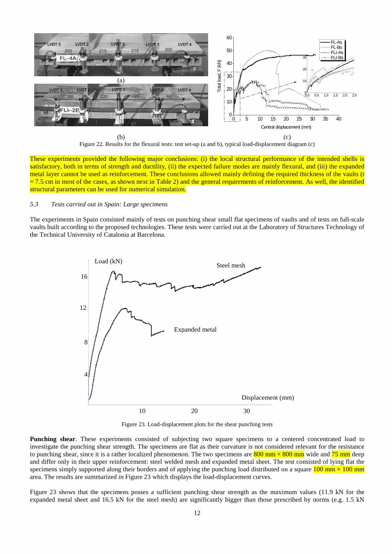
Figure 21. Tests of expanded metal sheet: (a) test set-up; (b) failure pattern and (c) stress-elongation response Shear tests in stack bonded masonry panels were carried out according to EN 1052–4 (2000), see (Lourenço et al. 2004) for details. To evaluate the behavior of the structural system when subjected to positive and negative bending moments, series of tests with the panel concrete layer turned upwards and downwards were carried out, see Figure 22). The shear resistance of the structural system was also evaluated by performing series of tests with a shear span ratio between 2.0 and 2.3. A total number of twenty reinforced masonry panels were tested. Figure 22(c) represents the average load-central deflection of the panels. Detailed analysis of this experimental program can be found in (Barros et al. 2005). It is noted that all panels failed in a bending ductile mode, except one that failed in shear. The loading configurations inducing negative moments are the most unfavorable for the proposed shell structural system. The results also indicate that brittle shear failure modes have low probability to occur.
0.00 0.04 0.08 0.12 0.16 0.20 0.240.0
0.2
0.4
0.6
0.8
1.0
Bond
stre
ss (M
Pa)
Displacement (mm)
0
3
6
9
12
15
0 20 40 60 80 100
DISPLACEMENT (mm)
LOAD
(kN)
M10-0M11-0M12-0
12
(a)
(b) (c) Figure 22. Results for the flexural tests: test set-up (a and b), typical load-displacement diagram (c)
These experiments provided the following major conclusions: (i) the local structural performance of the intended shells is satisfactory, both in terms of strength and ductility, (ii) the expected failure modes are mainly flexural, and (iii) the expanded metal layer cannot be used as reinforcement. These conclusions allowed mainly defining the required thickness of the vaults (t = 7.5 cm in most of the cases, as shown next in Table 2) and the general requirements of reinforcement. As well, the identified structural parameters can be used for numerical simulation. 5.3 Tests carried out in Spain: Large specimens The experiments in Spain consisted mainly of tests on punching shear small flat specimens of vaults and of tests on full-scale vaults built according to the proposed technologies. These tests were carried out at the Laboratory of Structures Technology of the Technical University of Catalonia at Barcelona.
Figure 23. Load-displacement plots for the shear punching tests
Punching shear. These experiments consisted of subjecting two square specimens to a centered concentrated load to investigate the punching shear strength. The specimens are flat as their curvature is not considered relevant for the resistance to punching shear, since it is a rather localized phenomenon. The two specimens are 800 mm × 800 mm wide and 75 mm deep and differ only in their upper reinforcement: steel welded mesh and expanded metal sheet. The test consisted of lying flat the specimens simply supported along their borders and of applying the punching load distributed on a square 100 mm × 100 mm area. The results are summarized in Figure 23 which displays the load-displacement curves. Figure 23 shows that the specimens posses a sufficient punching shear strength as the maximum values (11.9 kN for the expanded metal sheet and 16.5 kN for the steel mesh) are significantly bigger than those prescribed by norms (e.g. 1.5 kN
0 5 10 15 20 25 30 35 400
10
20
30
40
50
60
0.0 0.5 1.0 1.5 2.0 2.50
10
20
30
Tota
l load
, F (k
N)
Central displacement (mm)
FL-As FL-Bs FLI-As FLI-Bs
4
8
12
16
10 20 30
Load (kN)
Displacement (mm)
Steel mesh
Expanded metal

13
according to European regulations, European Committee for Standardization 2001) and than those expected for normal working conditions. In the specimen with steel welded mesh reinforcement the separation among consecutive bars was 25% bigger than the size of the loading area and such load was applied between two adjoining ribs; in spite of that, the resistance is higher for the specimen with the steel mesh and its behavior is more ductile. Tests on full scale vaults. Table 2 shows the main characteristics of the tested vaults (López-Almansa et al., 2010). The bricks and steel in the specimens were also tested to obtain their strengths and deformation moduli. Brick compressive or tensile strength is not considered relevant as the observed failure modes do not include brick failure. Steel yielding point is of relevance, since large elongations were detected. Both B 400 S (fyk = 400 MPa) and B 500 S (fyk = 500 MPa) steel types were used since they are contemplated by the Spanish regulations (EHE, 1999; UNE 36068, 1994) and are currently used in construction practices. In spite of these nominal values, yielding points obtained from testing ranged in between 550 and 600 MPa. The mortar strength has been determined according to European standard EN 1015-115 (1999).
Table 2. Full scale tested vaults (l = 1m)
Vault name
L × F × t × b (m)
nl × ns
Support conditions
Top / bottom reinforcement
(mm2 / m2)
Top / bottom
steel yielding
point (MPa)
Top / bottom
mechanical cover (mm)
Top / bottom mortar
strength (MPa)
Loading position
v0 4 × 1 × 0.075 × 1 3 × 1 Hinged ends 0 / 141.37 - / 400 - / 17 - -
v1 4 × 1 × 0.075 × 1 1 × 1 Hinged ends 0 / 141.37 - / 3 × 500
+ 2 × 400a - / 17 2.92 / 4.35 L / 2
v2 4 × 1 × 0.075 × 1 1 × 1 Hinged ends 141.37 / 251.33 400 / 500 42 / 13 2.09 / 3.34 L / 2
v3 4 × 1 × 0.075 × 2 2 × 1 Hinged
corners 141.37 / 141.37 400 / 8 × 500 + 2 ×
400b 42 / 13 4.578 / 4.578 L / 2
v4 4.1 × 0.34 × 0.075 × 1 1 × 1 Hinged ends 141.37 / 141.37
500 / 3 × 500 + 2 ×
400a 42 / 13 4.320 / 4.320 -
v5 6 × 1 × 0.075 × 1 1 × 1 Hinged ends 141.37 / 141.37
500 / 3 × 500 + 2 ×
400a 42 / 15 3.937 / 3.937 L / 3
v6 10 × 3.30 × 0.075 × 1 1 × 2 Clamped
ends 251.33 / 141.37 500 / 500 57 / 18 25.495 / 25.495 L / 4
v7 4 × 1 × 0.01 × 1 1 × 1 Hinged ends 141.37 / 251.33 500 / 500 67 / 13 25.097 / 25.097 -
v8 4 × 1 × 0.075 × 1 1 × 1 Hinged ends 141.37 / 251.33 500 / 500 22 / 16 41.420 /
41.420 L / 2
v9 4 × 1 × 0.075 × 1 1 × 1 Hinged ends 141.37 / 251.33 500 / 500 22 / 16 37.970 /
37.970 L / 2
v10 4 × 1 × 0.075 × 1 1 × 1 Hinged
(sliding) ends 141.37 / 251.33 500 / 500 22 / 16 36.580 / 36.580 L / 2
v11 6.50 × 4.47 ×
0.08 × 2 (asymmetric)
2 × 2 Hinged (elastic
sliding) ends 251.33 / 251.33 500 / 500 24 / 24 - -
a In the three inner bars fyk = 500 MPa and in the two outer ones fyk = 400 MPa b In one sheet fyk = 500 MPa in the three inner bars and fyk = 400 MPa in the two outer ones; in the other sheet fyk = 500 MPa in
all the bars
The structural experiments consisted of four types of loading tests: Line instantaneous loading; vaults v1, v2, v5, v6, v8, v9 and v10. The load is applied by a hydraulic jack up to failure; the
objective is to investigate the loading capacity and the ductility. Point instantaneous loading; vault v3. The objective is to investigate the importance of biaxial bending. Sustained loading; vault v7. The load is applied by cement bags; the objective is to investigate the creep behavior. Support displacement + line instantaneous loading; vault v10. A horizontal displacement of 45 mm of the supports was
applied, followed by a concentrated load until failure; the objective is to investigate the influence on the loading capacity of the lateral flexibility of the supporting members.

14
It is noted that vaults v0, v4, v7, v8 and v11 were not structurally tested. Figure 24 and Figure 25 show typical global views of the testing assemblies, for vaults v1 and v6, respectively. As shown in Figure 25, remote sensing was employed to control the geometry and deformation for vault v6.
Figure 24. Testing rig for vault v1
Figure 25. Testing rig for vault v6
Figure 26. Load-deflection relationship for vaults v9 and v10 Table 3 shows the main results for each of the tested vaults, in terms of collapse loads. A comparison between the values for vaults v9 and v10 shows a significant decrease in the ultimate vertical load because of the initial support displacement, see Figure 26. The reference (López-Almansa et al., 2010) contains a deeper discussion.
Support frame
Loading piston Loading frame
Support frame
Displacement sensor
Hinged connection
Frame for sensors
Vault
Remote measurement
Hydraulic jack
Loading platform
10 20
30
40 50
40 80 120 Deflection (mm)
Load (kN)
Vault v10
Vault v9

15
Table 3. Tests results
Vault v1 v2 v3 v5 v6 v7 v8 v9 v10 Collapse load (kN) 16.392 15.137 21.567 8.526 14.706 - 35.511 45.157 36.374
These experiments corroborated the conclusions of those in Portugal for local behavior. Moreover, the following new major conclusions were obtained: (i) the global structural performance of the intended vaults is satisfactory, both in terms of strength and ductility, (ii) the expected global failure modes are mainly flexural, and (iii) the proposed semi-prefabrication and technologies are feasible. As in the tests carried out in Portugal, the new identified structural parameters can be used for numerical simulation. 5.4 Tests in Italy: Prototypes The experiments in Italy consisted mainly of tests on full-scale vaults and prototypes built according to the proposed technologies, see also (da Porto et al., 2005). Characterization tests on the materials and additional experiments on flat specimens of vaults were also performed. All these tests were carried out at the University of Padua. Tests on materials. These tests deal with bricks of type B3 (see Figure 3(b)) and mortar. Structural and non structural experiments on the brick units were carried out in accordance to the testing methods for clay block for flooring (UNI 9730-3, 1990). The mean value of compressive strength in the direction parallel to the holes (on the gross cross sectional area) and in the direction orthogonal to the holes (on the shells area) and the mean value of the deformation modulus are reported in Table 4. In particular, the compressive strength orthogonal to the holes was determined on Siamese specimens. The tests revealed a good behavior of the unit; the lateral side wings for the placement of the re-bars did not present brittle phenomena. Non structural tests for the determination of the attitude to the efflorescence and of the water absorption were performed on simple units and on the units treated with an anti-salt product. In both cases, low or no tendency to efflorescence was revealed. The initial rate of water absorption was 15.5 g/dm2 min. The mortars adopted for the joints and for the topping, were selected among premixed commercially available products. The consistence of the mortars was measured according to EN 1015-3 (1998); it was 210 mm and 230 mm for the joints and topping mortars, respectively. The mechanical properties of the mortars were determined according to EN 1015-11 (1999) and UNI 6556 (1976), and are summarized in Table 4.
Table 4. Mechanical properties of mortars and bricks (MPa)
Mortar Flexural Strength
Mortar Compressive Strength
Mortar Elastic Modulus Bricks Compressive
Strength (parallel) Bricks Compressive
Strength (orthogonal)
Bricks Elastic
Modulus Joints Topping Joints Topping Joints Topping 5.1 5.2 17.7 23.9 15680 25840 43.4 19.28 8350
Tests on flat specimens of vaults. Unidirectional flexural tests were carried out on two square specimens (about 1 × 1 m2) built with longitudinal joints 20 mm and 30 mm wide, respectively. Figure 27 shows the testing rig.
Figure 27. Test set-up Figure 28(a) displays a picture describing the failure of the panel with 30 mm joints and Figure 28(b) shows the vertical load-mid span deflection diagram for the two tested panels. The joints width did not strongly affect the ultimate capacity.

16
(a) (b)
Figure 28. Panel at collapse (a) and load-deflection diagram for both panels (b)
Tests on a laboratory full scale vault. A 1:1 scale model of the prototype vaults to be built in Italy was constructed and tested. The geometrical parameters are: span length L = 8 m, rise F = 2.5 m and thickness t = 0.1 m (Figure 1). Two types of experiments were carried out: dynamic vibration tests and static loading under load control, using a line load at 2.6 m from the support. Figure 29 shows the testing rig for the static test. The static test consisted of an initial loading-unloading cycle up to 10 kN and a second loading phase until the final capacity of the vault. Figure 30 displays, for both loading phases, the applied force vs. the vertical displacement of the loaded section.
Figure 29. Sensors and actuator for the static loading of the laboratory vault built in Italy
Figure 30. Force-displacement plots for the laboratory vault built in Italy Figure 30 shows a permanent displacement after the first cycle, indicating some damage as confirmed by the dynamic identification tests, whose results are included in Table 5. On the second loading phase the test was stopped when two main hinges were clearly visible, one under the loading position and the other symmetrically placed. It is worth stressing that the structure exhibited considerable ductility. The dynamic tests consisted of vibration tests with excitation generated by an instrumented hammer. Five accelerometers were installed to register the responses at several points of the vault, and these outputs allowed measuring the natural frequencies and the mode shapes. These tests were performed twice, namely prior to the static loading and after the first loading cycle, in order to investigate the influence of the damage in the dynamic parameters. Table 5 shows the first three frequencies in both cases. The relatively low decrease of the natural frequencies indicates that the damage due to the load cycle was marginal.
-5 0 5 10 15 20 25 30 35
0
10
20
30
40
50
60 Load (kN) (2 cm) Load (kN) (3 cm)
Forc
e (k
N)
Displacement (mm)
-5 0 5 10 15 20 25 30 35 40-2
0
2
4
6
8
10
12
14
16
18
20
22
Forc
e (k
N)
Displacement (mm)
Load (1) (kN) Load (2) (kN)

17
Table 5. First three natural frequencies before and after the first loading cycle (Hz)
Mode Prior to test After load cycle 1 6.84 6.46 2 15.05 14.58 3 25.44 24.36
Tests on the prototype buildings. Two prototype buildings were built at Matera and at Ronco all’Adige in Italy; their characteristics were selected to complement the conclusions derived from the experiments carried out in Spain and to fit the particular requirements of the ISO-BRICK project. The shapes of the vaults are equal to the one of the laboratory model described in Figure 29; edge beams were incorporated to provide lateral support. Both buildings were submitted to static loading-unloading cycles similar to those of the laboratory model. Figure 31 describes the testing set-up and Figure 32 shows, for both buildings, the applied force vs. the vertical displacement of the loaded section. The diagrams from Figure 32 show similar results for both buildings. However, the Ronco all’Adige vault exhibited a significant permanent displacement, which can arise from poor curing and from premature loading.
Figure 31. Testing rig for the prototype buildings
Figure 32. Load-deflection plots for the prototype buildings These experiments corroborated the conclusions of those in Portugal and Spain for local and global behavior, respectively. Moreover, the following new major conclusions were obtained: (i) the proposed semi-prefabrication and technologies are feasible under normal operation conditions (e.g., not only in a laboratory), (ii) the structural behavior can be satisfactory described with the derived numerical models. About this last issue, noticeably, the edge beam (see Figure 2 and Figure 31) behaved as predicted.
0,0 0,4 0,8 1,2 1,60,0
0,5
1,0
1,5
2,0
2,5
Forc
e (k
N)
Deflection (mm)
Matera load (kN) Ronco load (kN)

18
6 Numerical modeling 6.1 Derived analysis tools The availability of reliable and accurate numerical models of the structural behavior is crucial to the spread and improvement of any construction technology. In general, it is advisable to derive two types of algorithms: (1) a sophisticated and accurate nonlinear finite element model able to account for all the relevant structural issues, to provide comprehensive information about the response and to allow parametric studies and (2) a simpler algorithm capable to cope only with the most relevant issues and provide the necessary design information. Due to its inherent complexity and computational cost, the first model is not envisaged as a practical design tool rather as an instrument to derive general conclusions or to deal with complex or daring solutions; conversely, the second model is mainly intended for daily use in less complex cases where a sound experience exists. Obviously, the accuracy and reliability of both codes has to be checked with experimental results. Two algorithms lying within these categories have been developed. The first one is called PRO-SHELL while the second one is termed DBS-ROOF. 6.2 PRO-SHELL PRO-SHELL is an advanced nonlinear finite element code (Hanganu, Oñate and Barbat, 2002) aimed at simulating up to failure possible situations affecting the structural performance of the proposed roofs. PRO-SHELL is able to reproduce second-order static/time-dependent/dynamic shell behavior accounting for large displacements. Creep is described by a Kelvin model and dynamic capabilities refer both to linear modal analysis and to nonlinear transient response using the Newmark method. Direct and indirect actions can be simulated, together with quasi-brittle (brick units, mortar) and plastic (steel) material behavior. Quasi-brittle mechanical nonlinearities are described by a multiaxial isotropic damage model (Hanganu, Oñate and Barbat, 2002), while a conventional uniaxial plastic model with strain hardening is used for steel. The required parameters for brick units and mortar are the deformation moduli, the tensile and compressive strength and the Poisson’s ratio; their values are derived from the tests. Steel is described by a uniaxial bilinear plastic model without strain hardening; the yielding point and the deformation modulus are obtained from testing and the maximum longitudinal strain is 20%. The vaults are modeled by 3D parallelepiped elements with 20 nodes and three DOF per node. Following a micro-modeling approach, each material (steel, bricks and mortar) is represented independently, while no special materials are used for interfaces. The contribution of the expanded metal sheet to the stiffness and strength is neglected as confirmed by testing (Oliveira, et al. 2002). The pre- and post-processing user interfaces are eased through GiD code (CIMNE, 2007). Figure 33(a) shows a FE mesh for vault v11 including a column and an edge beam. Figure 33(b) shows the computed damage distribution for vault v5 in a situation near collapse. Damage index ranges between 0 (no damage) and 1 (destruction).
(a) (b)
Figure 33. Finite element analysis with PRO-SHELL. Mesh for vault v11 (a) and damage distribution near collapse for vault v5 (b)
6.3 DBS-ROOF Under concentrate loading the ultimate strength is mainly governed by the ductile formation of transversal hinges as confirmed by all the experiments and by all the numerical simulations using PRO-SHELL (see Figure 33(b)), which suggests that one-dimensional limit analysis yields accurate estimations of the collapse loads and failure modes. This idea has motivated the development of DBS-ROOF code (Roca et al. 2006). It consists of a simple plastic model of the ultimate capacity of reinforced arches based on the plasticity theory applied to arches according to Heyman’s formulation (Heyman, 1982). This formulation is based on the static approach of limit analysis and consists of applying the so-called Safe and Uniqueness Theorems. The main innovation consists of representing the reinforcement in terms of equivalent depth increase, the failure criterion being that the thrust line lies inside the two effective bounds. Figure 34 displays an example of thrust

19
lines. The collapse mechanism is formed by two hinges located in the intersections between such lines and the effective boundaries.
Figure 34. Thrust lines derived from DBS-ROOF 7 Comparison between numerical and experimental results The tests on vaults carried out at Spain were simulated with PRO-SHELL and DBS-ROOF to assess their accuracy and reliability. Table 6 presents the numerical and experimental collapse loads. The predicting accuracy of both numerical tools is satisfactory, given the complexity of the analyzed structural systems and the uncertainties in the geometrical and mechanical parameters. In vault v6 two possibilities were considered for the supported conditions, namely hinged and clamped ends, being the real situation intermediate. Moreover, a nonlinear geometric analysis was performed with PRO-SHELL. The collapse load was slightly lower than the first order one and fits better the experimental value. The observed strength reduction of vault v10 (about 20%, compared to v9) due to the supports opening (45 mm) could not be reproduced by PRO-SHELL which predicted a dramatic decrease for openings larger than 40 mm. This might be due to the difficulty of simulating the ultimate behavior by continuum mechanics because of the possible discrete opening of masonry joints and the sliding of the reinforcement. An obvious conclusion is that these vaults seem to have more ductile behavior than predicted by a continuous damage model. Figure 35 displays the experimental load-deflection plots of vaults v2, v5 and v9 and the curves of the simulation by PRO-SHELL. Comparison among both sets of results shows a good accuracy, even near collapse. Other comparisons with previous tests (Sarrablo, 2002) yielded similar degrees of accuracy.
Table 6. Comparison between numerical and experimental results. Collapse loads (kN)
Vault v1 v2 v3 v5 v6 v8 v9 v10 Experimental results 16.392 15.137 21.567 8.526 14.706 35.511 45.157 36.374
PRO-SHELL 16.50 16.30 24.00 7.70 12.70a / 20.70b / 18.90c 45.40 45.40 - DBS-ROOF 16.20 17.30 22.00 9.00 10.60a / 15.80b 43.50 43.50 -
aHinged ends; bClamped ends; cSecond order analysis with clamped ends.
Load (kN)
Displacement (mm)
50
40
30
20
10
30 20 10 60 50 40
v9
v2
v5
Experimental Numerical
material boundaries
strength boundaries (Safe)
strength boundaries (Uniqueness)

20
Figure 35. Experimental and simulated results for vault v5
The experiments of the laboratory vault (see Figure 29) and of the prototype buildings built at Italy were simulated with Straus7 (Strand7, 2005) and PRO-SHELL computer programs. Straus7 was used to reproduce the dynamic tests while PRO-SHELL was considered to simulate the static proofs. Straus7 provided the following values for the first three natural frequencies: 7.12 Hz (1st mode), 15.07 Hz (2nd mode) and 16.37 Hz (3rd mode). Comparison with the experimental results included in Table 5 shows a reasonable accuracy given the complexity of the vault and the uncertainty in the material parameters. The mode shapes are also close to the experimentally determined. PRO-SHELL predicted a collapse load 23.57 kN, quite close to the measured value (about 22.97 kN, see Figure 30). Figure 36 displays the deformed shape.
Figure 36. Simulated deformed shape near collapse for the laboratory vault built at Italy 8 Conclusions Regarding the proposed technology, the main conclusion is that is feasible. The production is divided in two phases: semi-prefabrication and on-site construction. The first phase is inexpensive, robust, easily verifiable, secure, error-free, does not require qualified personnel nor advanced facilities and can be easily systematized. In both phases the security issues have been of main concern. Regarding the structural behavior, two major conclusions arise: (a) is adequate and (b) can be properly simulated with the derived numerical tools. The structural performance is satisfactory in terms of ductility and strength, both for direct and indirect actions; this conclusion is supported by testing and by numerical simulation. The finite element code PRO-SHELL can reproduce the structural behavior virtually until collapse while the simpler model DBS-ROOF can predict the ultimate loading capacity with a reasonable degree of accuracy. Finite element linear models are adequate for describing the behavior prior to any damage.
ACKNOWLEDGEMENTS This work has received financial support from the Catalonian Government (CIDEM, “CERARMAT” IT –Technological Innovation– project 605) the Spanish Government (Ministry of Industry and Energy, “PRECERAM” ATYCA project M172/1999) and the European Commission (“ISO-BRICK” CRAFT –Cooperative Research– Project G5ST-CT-2001-50095). All these supports are gratefully acknowledged. References [1] Anderson, S. Eladio Dieste: Innovation in Structural Art. Princeton Architectural Press, New York, 2004. [2] Barros, J.A.O., Lourenço, P.J.B., Oliveira, J.T., Bonaldo E. Contribution for a Full Prefabrication Approach of
Masonry Reinforced Shells. Technical report 03-DEC/E-05, Dep. Civil Eng., School Eng. University of Minho, 15 p., February 2003.
[3] Barros J.A.O., Oliveira J.T., Bonaldo E., Lourenço P.B., Flexural behavior of reinforced masonry panels. ACI Structural Journal. 103(3) pp. 418-426 (2006).
[4] CIMNE. GiD program. The personal pre-post processor. The Universal adaptive and user-friendly pre and post processing system for computer analysis in science and engineering. CIMNE, Barcelona, Spain (2007). Available from
21
http://www.gidhome.com. [5] da Porto F., Casarin F., Garbin E., Grendene M., Modena C., Valluzzi M.R. Design Assisted by Testing of Semi-
Prefabricated Reinforced Brick Masonry Vaults. 10th Canadian Masonry Symposium, Banff (2005). [6] Daguerre M. Eladio Dieste 1917-2000. Ed. Mondadori Electa (2003). [7] EHE. Instruction about Structural Concrete (in Spanish). Spanish Ministry of Public Works, (1999). [8] EN 10 002–1. Metallic materials – Tensile testing, Part 1: Method of test (at ambient temperature). Brussels (1990). [9] EN 1015-3: Determination of consistence of fresh mortar by flow table (1998). [10] EN 1015-11: Determination of flexural and compressive strength of hardened mortar (1999). [11] EN 1052-4 : Determination of shear strength including damp proof course (2000). [12] European Normalisation Committee. Deformed steel weldable bars for reinforced concrete (in Spanish). UNE
36068:1994 (1994). [13] European Committee for Standardization. EN 772-1:2000. “Methods of test for masonry units. Part 1: Determination of
compressive strength”. CEN/TC125, 2001. [14] Friedman D. Analysis of archaic fireproof floor systems. Structural Analysis of Historic Construction (2008). [15] Hanganu A.D., Oñate E., Barbat A.H. A finite element methodology for local/global damage evaluation in civil
engineering structures. Computers & Structures; 80 1667-1687 (2002). [16] Heyman J. The masonry arch. Ellis Horwood Limited, (1982). [17] Huerta, A. (Antonio Becchi; Massimo Corradi; Federico Foce; Orietta Pedemonte Editors). Essays on the History of
Mechanics: In Memory of Clifford Ambrose Truesdell and Edoardo Benvenuto. 256 pp., Basel/Boston: Birkhäuser, 2003. Article from Santiago Huerta, “The Mechanics of Timbrel Vaults: A Historical Outline”.
[18] ISO-BRICK (Industrial Solutions for Construction of Reinforced Brick Masonry Shell Roofs) Craft Research Project. Deliverable # 37. Report about the Proposed Technologies (non-confidential). European Commission 2004.
[19] López-Almansa F., Roca P., Sarrablo V., Cahís X. and Canet J.M. Experiments on reinforced brick masonry vaulted light roofs. ACI Structural Journal. To be published.
[20] Lourenço P.B., Almeida J.C., Barros J.A. Experimental investigation of bricks under uniaxial tensile testing. Masonry International, 18(1), pp.11-20 (2005).
[21] Lourenço P.B., Barros J.O., Oliveira J.T. Shear testing of stack bonded masonry. Construction and Building Materials. 18, pp.125-132 (2004).
[22] Oliveira J.T., Barros J.O., Lourenço P.B., Marques Pinho A. Uniaxial testing of expanded metal sheet. Report 02-DEC/E-11. University of Minho (2002). Available from www.civil.uminho.pt/masonry.
[23] Oliveira, J.T., Barros, J.A.O., Lourenço, P.J.B., Pinho A.M. Uniaxial testing of expanded metal sheet. Technical report 02-DEC/E-12. Dep. Civil Eng., School Eng. University of Minho, 33 p., October 2002.
[24] Pedreschi, R. Eladio Dieste. The Engineer's Contribution to Contemporary Architecture. Thomas Telford, London, 2000. [25] Piaggio J.M. The shell vaults in reinforced brick masonry (in Italian). Costruire in Laterizio (www.laterizio.it) n° 107
2005 60-73. Gruppo Editoriale Faenza Editrice S. p. A. [26] Roca P., López-Almansa F., Miquel J., Hanganu A. Limit Analysis of Reinforced Masonry Vaults. Engineering
Structures. Vol. 29, Núm. 3 Pág. 431-439 (2007). [27] Sarrablo V. Contribution to the feasibility of Reinforced Masonry Shell Roofs through semi-prefabricated solutions.
Proposal for short span shells (in Spanish), Ph.D. Thesis, Architecture Structures Department, Technical University of Catalonia, 2002.
[28] Strand7. Theoretical Manual (2005). Available from http://www.strand7.com.