Regulatory Guide 1.161 (Draft was DG-1023) Evaluation of - NRC
40
U.S. NUCLEAR REGULATORY COMMISSION REGULATORY GI OFFICE OF NUCLEAR REGULATORY RESEARCH REGULATORY GUIDE 1.161 (Draft was DG-1023) EVALUATION OF REACTOR PRESSURE VESSELS WITH CHARPY UPPER-SHELF ENERGY LESS THAN 50 FT-LB. USNRC nEGUIATOU GUIDES Regulatory Guides are Issued to describe and make available to the ptuIbio such Information as methods acceptable to the NRO staff for Implement ing specific parts of the Commission's regulations, techniques used by the staff in evaluating specific problems or postulated accidents, and data needed by the NRC staff In Its review of applications for permits and licenses. Regulatory guides are not substitutes for regulations, and com pliance with them Is not required. Methods and solutions different from those set out In the guldes will be acceptable If they provide a basis for the findings requIsite to the Issuance or continuance of a permit or license by the Commission. This guide was Issued after consideration of comments received from the public. Comments and suggestions for Improvements in these guldes are encouraged at all times, and guides wii = be revised, as apprprrate, to accommodate comments and to reflect new Information or experience. June 1995 UIDE Written comments may be submitted to the Rules Review and Directives Branch, DFRPS, ADM, U.S. Nuclear Regulatory Conrvnsslon, Washing ton, DC 20555-0001. The guides are Issued In the following ten broad divisions: 1. Power Reactors S. Products 2. Research and Test Reactors 7. Transportation 3. Fuels and Materials Facilities 8. Occupational Health 4. Environmental and Siting :. Antitrust and Financial Review 5. Materials and Plant Protection 10. General Single copies of regulatory guides may be obtained free of charge by writ ing the Office of Administration, Attention: Distribution and Services Section, U.S. Nuclear Regulatory Commission, Washington, DC 206565-0001; or by fax at (301)415-2260. Issued guides may also be purchased from the National Technical Infor matlon Service on a standing order basis. Details on this service may be obtained by writing NTIS, 5285 Port Royal Road, Springfield, VA 22161.
Transcript of Regulatory Guide 1.161 (Draft was DG-1023) Evaluation of - NRC
U.S. NUCLEAR REGULATORY COMMISSION
REGULATORY GI OFFICE OF NUCLEAR REGULATORY RESEARCH
REGULATORY GUIDE 1.161 (Draft was DG-1023)
EVALUATION OF REACTOR PRESSURE VESSELS WITH CHARPY UPPER-SHELF ENERGY LESS THAN 50 FT-LB.
USNRC nEGUIATOU GUIDES
Regulatory Guides are Issued to describe and make available to the ptuIbio such Information as methods acceptable to the NRO staff for Implementing specific parts of the Commission's regulations, techniques used by the staff in evaluating specific problems or postulated accidents, and data needed by the NRC staff In Its review of applications for permits and licenses. Regulatory guides are not substitutes for regulations, and compliance with them Is not required. Methods and solutions different from those set out In the guldes will be acceptable If they provide a basis for the findings requIsite to the Issuance or continuance of a permit or license by the Commission.
This guide was Issued after consideration of comments received from the public. Comments and suggestions for Improvements in these guldes are encouraged at all times, and guides wii = be revised, as apprprrate, to accommodate comments and to reflect new Information or experience.
June 1995
UIDE
Written comments may be submitted to the Rules Review and Directives Branch, DFRPS, ADM, U.S. Nuclear Regulatory Conrvnsslon, Washington, DC 20555-0001. The guides are Issued In the following ten broad divisions:
1. Power Reactors S. Products 2. Research and Test Reactors 7. Transportation 3. Fuels and Materials Facilities 8. Occupational Health 4. Environmental and Siting :. Antitrust and Financial Review 5. Materials and Plant Protection 10. General
Single copies of regulatory guides may be obtained free of charge by writing the Office of Administration, Attention: Distribution and Services Section, U.S. Nuclear Regulatory Commission, Washington, DC 206565-0001; or by fax at (301)415-2260. Issued guides may also be purchased from the National Technical Informatlon Service on a standing order basis. Details on this service may be obtained by writing NTIS, 5285 Port Royal Road, Springfield, VA 22161.

CONTENTS
* A. INTRODUCTION .............................................................................. 1
B. DISCU SSION .................................................................................. I
NOMENCLATURE .............................................................................. 2
C. REGULATORY POSITION ....................................................................... 3
1. ACCEPTANCE CRITERIA ................................................................ 3 1.1 Levcl A mnd B Conditions ........................................................... 3 1.2 Leve C Condition ................................................................. 3 1.3 Level D Condition ................................................................. 4
2. ANALYSIS M ETHODS ................................................................... 4 2.1 Level A mnd B Conditions ........................................................... 4 2.2 Level C Condition ................................................................. 7 2.3 Level D Condition ................................................................. 8
3. MATERIAL PROPERTIES ................................................................ 8 3.1 Welds Made Using Linde 80 Flux .................................................... 9 3.2 Generic Reactor Pressure Vessel Welds ............................................... 9 3.3 Reactor Pressure Vessel Base (Plate) Materials ......................................... 9
4. TRANSIENT SELECTION ............................................................... I I 4.1 Plant-Specific Transients .......................................................... I 4.2 Bounding Transients .............................................................. 1
D. IM PLEM ENTATION ........................................................................... 11
REFERENCES ........................................................................................ 12
APPENDIX A: Examples ............................................................................. A-1
APPENDIX B: Computation of Stress Intensity Factors ...................................................... B-l
REGULATORY ANALYSIS ............................................................................ R-l
m.°

A. INTRODUCTION
> Appendix 0. Fracture Toughness Requirements" to 10 CFR Part 50, "Domestic .Licensing of Production and Utilization Facilities," requires, in part, that the reactor vessel betline materials ". . must have Charpy upper- shelfnergy of no less than 75 fl-lb (102J) initially and must maintain upp•r-shelf energy throughout the life of the vessel of no less than 50 ft-lb (68J), unless it is demotrated in a manner approved by the Director, Office of Nuclear Reactor Regulation, that lower values of upper-shelf energy will provide margin of safety against fracture equivalent to those required by Appe.ndx 0 of the ASME Code."' Charpy uppcr-shelf energy is defined in ASTM E 185-79 (Ref. 1) and -82 WR 2), which are incorporated by reference in Appendix KL
"Reactor Vessel Material Surveillance Program Requirements to 10 CFR Part 50. This guide describes general procedures acceptable to the NRC staff for demonstrating equivalence to the margins of safety in Appendix 0 of the ASME Code (Ref. 3). Several examples using these procdures are presented in Appendix A to this guide and in more detail in NUREG/CR-6023 Ref. 4).
This regulatory guide contains information collections that are subject to the Paperwork Reduction Act of 1980 (44 U.SC. 3501 et seq.). This regulatory guide has been submitted to the Office of Management and Budget for review and approval of the information collections. These information collections and record keeping are needed for demonstrating compliance with Appendix 0 to 10 CFR Part 50 for the remaining duratienofthe plants license if Charpy upper-shelf energy ofthe materials in the beitline region may drop, or may have dropped, below the 50 ft-lb regulatory limit
The public reporting burden for this collection of information is estimated to average 960 hours per response, including the time for reviewing instructions, semrcing existing data sources, gathering and mAinta;nin the data needed, and completing and reviewing the collection of ifnnation. Send comments regarding this burden estimate or any other aspect of this collection of information, including suggestions for further reducing the reporting burden, to the Information and Records Management Branch (T6F33), U.S. Nulear Regulatory Caomission, Washington DC 20555; and to the Desk Officer, Office of Information and Regulatory Affairs, NEOB-10202 (3150-0011), Office of Management and Budget, Washington, DC 20503.
B. DISCUSSION
The problem of evaluating materials that do not satisfy the 50 ft-lb upper-shdf enry requirement was recognized by the NRC staff several years ago and was designated Unresolved Safety Issue A-1 1, "Reactor Vessel Materials Toughness." In 1982, the staffcompleted resolution ofUSI A-l I by issuing NUREG-0744, "Resolution of the Task A-1l Reactor "Vessel Materials Toughness Safety Issue (Ref. 5), which
provided methods for evaluating the fracture behavior of these materials. Further, Generic Letter 82-26 (Ref. 6) was issued to advise licensees of the USI resolution. No new requirements were implemented as part of the USI resolution. However, neither NUREG-0744 nor Generic Letter 82-26 contained criteria for demonstrating equivalence of margins with Appendix 0 of the ASME Code. Rather, the NRC staff asked Section X) of the ASME Boiler Pressure Vessel Code Committee to develop and suggest to the staff appropriate criteria.
In February 1991, the Chairman of the ASME Section XI Subgroup on Evaluation and Standards provided to the NRC staffcriteria that had been developed by members of the Working Group on Flaw Evaluation (WGFE) and the Working Group on Operating Plant Criteria (WGOPC) (Ref 7). Although these criteria did not represent ASME Code criteria, they did represent the best opinion of knowledgeable persons familiar with the problem and with the ASME Code.
Upon review, the NRC staff found these criteria to be acceptable for denstrating margins of safety equivalent to those in Appendix 0 of the ASME Code (Ref. 3). However. specific methods for evaluating the criteria still were being developedby the ognizant ASME Code committees. Further, those efforts were not expected to provide specific guidance on determining event sequences and transients to be considered, nor were they exected to provide specific guidance on approprit material properties.
This guide has been developed to provide comprehensive guidance acceptable to the NRC staff for evaluating reactorpressure vesses when the Charpy upper-shelf energy falls below the 50 ft-lb limit of Appendix G to 10 CFR Part 50. The analysis methods in the Regulatory Position are based on methods developed for the ASME Code, Section XI, Appendix K ( 8). The staff has reviewed the analysis methods in Appendix K and finds that they are echnically acceptable but are not complete, because Appendix K does not provide information on the selection of transients and gives very little detail on the selection of material properties. In this regulatory guide, specific guidance is provided on selecting transients for consideration and on appropriate material properties to be used in the analyses.
Ductile tearing is the dominant fracture process in the upper-shelf region of the Charpy impact energy versus a .aim fnveor RPV materials. The conditions govern
ing cleavage mode-conversion of the ductile tearing process in materials with low Charpy upper-shelf energy are still not well understood and are not considered in this regulatory guide.
The material property needed to characterize ductile taring in the analysis methods in this regatory guide is the material's J-integral fracture resistance, the J-R curve. This curve is a function of the material, the irradiation condition, the loading rate, and the material temperature. The curve is detrmined by testing the specific material, uider the conditions of interest, in accordance with the American Society for
1.161-1

Testing and Materials Standard Test Method E 1152-87, "Standard Test Method for Determining J-R Curves' (Ref. 9).
Unfortunately, the specific material of interest (Le., the material from the beltline region of the reactor vessel under operation) is seldom available for testing. Thus, testing programs have used generic materials that are expected to represent the range of actual materials used in fabricating reactor pressure vessels in the United States. Statistical analyses of these generic data have been performed and reported in NUREG/CR-5729, -Multivariable Modeling of Pressure Vessel and Piping J-R Data' (Ref. 10). These analyses provide a method for determnining the material's Jintegral fractre resistance that the NRC staff finds acceptable for use in the methods described in this guide. Other methods for determining the material property may be used on an individual-case basis ifjustified.
NOMENCLATURE
The following terms are used in this regulatory guide and its equations
a The flaw depth, which includes ductile flaw growth (in inches).
a, The effective flaw depth, which includes ductile flaw growth and a plastic-zone correction (in inches).
a*. The effective stable flaw depth, which includes ductile flaw growth and a plastic-zone correction (in inches).
a,*. The effective stable flaw depth at tensile instability of the remaining ligament, which includes ductile flaw growth and a plastic-zone correction (in inches).
a. The postulated initial flaw depth (in inches).
2c The total flaw length, which includes ductile flaw growth (in inches).
B, Net-section thickness of the ASTM E 1152-87 (Ref. 9) test specimen used in determining material tearing resistance, J-R curve, behavior (in inches).
Cl ,C2 Coefficients used in the equation for the C3, C4 material tearing resistance, J-R curve.
CR The cooldown rate ('F/hour).
CVN Charpy v-notch upper-shelf energy (fl-lb.).
E Young's modulus of elasticity (ksi).
E' /(_v2)O (ksi).
F,. F2, F3 Geometry factors used to calculate the stress intensity factors (dimensionless).
Jww The J-integral from the applied loads (in.-lb/i. 2).
Jm,.ia The material's J-integral fracture resistance (in.lb/in.2), J-R curve.
jai The material's J-integral fracture resistance at a ductile flaw growth of 0.10 in. (in.-lb/'in).
KI& The mode I stress intensity factor caused by the radial thermal gradient through the cladding applied to the vessel inner surface, calculated with no plastic zone correction (ksi Ain.).
KV The mode I stress intensity factor caused by the internal pressure, calculated with no plastic-zone correction (ksi 4tin.); K,.' and K.m are the axial and circumferential values, respectively.
4ý K,, calculated with a plastic-zone correction (ksi fin.).
K1 The mode I stress intensity factor caused by the radial thermal gradient through the vessel wall, calculated with no plastio-zone corroection
Y.; K. calculated with a plastio-zone correction (ksi
'in.).
p Internal pressure (ksi).
p. The maximum accumulation pressure as defined in the plant-specific Overpressure Protection Report, but not eceding 1.1 times the design pressure (ksi).
1• The inner radius of the vessel (in inches).
SF The safety factor (dimensionless).
t The wall thickness of the vessel's base metal (in inches).
The sum of the vessel wall thickness, t, and the cladding thickness, t.L (in inches).
tlL The thickness of the stainless steel cladding applied to the vessel inner surface (in inches).
T Metal tWeraturp, at crack-tip, used in the analysis ('F).
1.161-2

WF The margin factor = 2 standard deviations on test data (dimensionless).
A reference material's flow stress, specified as 85 ksi in ASME Section XI, Appendix K (Ref. 8), on Charpy upper-shelf energy.
of
The following criteria are acceptable to the NRC staff for demonstrating that the margins of safety against ductile fracture are equivalent to those in Appendix 0 to Section III of the ASME Code. Licensees may follow this regulatory guide to determine the equivalent safety margins, or they may use any other methods, procedures, or selection of materials data and transients to demonstrate compliance with Appendix o to 10 CFR Part 50. If licensees choose to follow this regulatory guide, they must use the acceptance criteria, analysis methods, material properties, and selection of transients as described in this regulatory guide. The acceptance criteria are to be satisfied for each category of transients, namely, Service Load Levels A and B (normal and upset), Level C (emergenc), and Level D (faulted) conditions. These
service load levels are described in Standard Review Plan 3.9.3 (Ref 11). Because of differences in acceptable outcome during the various sevice load levels, different criteria have been developed for Levels A and B, C, and D.
1.1 Level A and B Conditions
When the upper-shelf Charpy energy of the base metal is less than 50 ft-lb, postulate both axial and circumferential interior flaws and use the toughness properties for the corresponding orientation. For a weld with Charpy upper-shelf energy less than 50 fl-lb, postulate an interior surface flaw oriented along the weld of concern and orient the flaw plane in the radial direction. Postulate a semi-elliptical surface flaw with an aht = 0.25 and with an aspect ratio of 6-to-I surface length to flaw depth. A smaller flaw size may be used on an individual-case basis ifjustified. Two criteria must be satisfied as described below. The maximum accumulation pressure, discussed below, is the maximum pressure defined in the Over Pressure Protection Report that satisfies the requirement of Section III, NB-731 1(b), of the ASME Code (Re 12).
1.1.1 The crack driving force must be shown to be less than the material toughness as given by Equation 1:
(1)
where J,, is the J-integral value calculated for the postulated flaw under pressure and thermal loading where the assumed pressure is 1.15 times the maximum accumulation pressure, with thermal loading using the plant-specific heatup and cooldown conditions. The parameter J,, is the J-integral characteristic of the material's resistance to ductile tearing Q...), as denoted by a J-R curve test, at a crack extension of 0.1 inch.
1.1.2 The flaw must be stable under ductile crack growth as given by Equation 2:
< C'V 8a a a
(with load held constant)
(2)
at
= p~fod = lal
where J,•. is calculated for the postulated flaw under pressure and thermal loading for all service level A and B conditions where the assumed pressure is 1.25 times the maximum accumulation pressure, with thermal loading, as defined above. The material's J-integral fracture resistance should represent a conservative estimate of the data for the vessel material under evaluation (i.e., mean - 2 standard deviations). Methods for determining the J-integral fracture resistance, J-R curve, are discussed in Regulatory Position 3 of this guide. Methods for determining the appropriate service level conditions are discussed in Regulatory Position 4 of this guide.
1.2 Level C Condition
When the Charpy upper-shelf energy of the base metal is less than 50 ft-lb, postulate both axial and circumferential interior flaws and use the toughness properties for the correspending orientation. When the Charpy upper-shelf energy of any weld material is less than 50 ft-lb, postulate an interior surface flaw with its major axis oriented along the weld of concern and the flaw plane oriented in the radial direction. Consider postulated surface flaws with depths up to one-tenth the base metal wall thickness, plus the clad thickness, but with te total depth not to exceed 1.0 inch (2.54 cm) and with an aspect ratio of 6-to- I surface length to flaw depth. A smaller maximum flaw depth may be used on an individual-cas basis if justified. For these evaluations, two criteria must be satisfied.
11.1 The crack driving force must be shown to be less than the material toughness as given by Equation 3:
aWpped < Jo.1 (3)
1.161-3
1, The material's yield stress (ksi).
v Poisson's ratio (dimensionless), specified as 0.3.
C. REGULATORY POSITION
1. ACCEPTANCE CRITERIA
J~vpied < J0.1

where J., is the J-integral value calculated for the postulWted flaw in the beltline region of the reactor vessel under the governing Service Level C condition, with a safety factor of 1.0 on the applied loading. J01 is the J-integral characteristic of the material resistance to ductile tearing (JQ..), as denoted by a J-R curve test, at a crack extension of 0.l inch.
1.,2 The flaw must also be stable under ductile crack growth as given by Equation 4:
8a aa(4)
(with load held constant) at
i'amp~~ = Jtmlt,1
where Jo is calculated for the postulated flaw under the governing Service Level C condition, with a safety factor of 1.0 on the applied loading. The material's J-integral fracture resistance hould represent a conservative estimate of the data for the vessel material under evaluation (i.e., mean - 2 standard deviations). The J-integral resistance versus crack growth, J-R curve, is defined in Regulatory Position 3 of this guide. Determination of the appropriate service level conditions is discussed in Regulatory Position 4 of this guide.
1.3 Level D Condition
When the Charpy upper-shelf energy of the base metal is less than 50 ft-lb, postulate both axial and circumferential interior flaws and use the toughness properties for the correspending orientation. When the Charpy upper-shelf energy of any weld material is less than 50 ft-lb, postulate an interior semi-elliptic surface flaw with the major axis oriented along the weld of concern and the flaw plane oriented in the radial direction. Consider postulated surface flaws with depths up to one-tenth the base metal wall thickness, plus the clad thickness, but with total depth not to exceed 1.0 inch (2.54 cm) and with an aspect ratio of 6-to-I surface length to flaw depth. A smaller maximum flaw depth may be used on an individual case basis if justified.
For these evaluations, the postulated flaw must be stable under ductile crack growth as given by Equation 5:
at
(5)
(with load held constant)
Jw1'ppWia = J.mWAial
where J.3P is calculated for the postulated flaw under the governing Service Level D condition, with a safety factor of 1.0 on the applied loading. Additionally, the flaw depth,
including stable tring, should not be greater than 75% of the vessel wall thickness, and the remaining ligament should be safe from tensile instability. The material's J-integral fracture resistance should reflect a best estimate, Le., the mean value, of the data representative of the vessel material under evaluation.
The J-integral resistance versus crack growth, J-R curve, is discussed in Regulatory Position 3 of this guide. Methods for determining the appropriate service level conditions are discussed in Regulatory Position 4 of this guide.
2. ANALYSIS METHODS
The analysis methods described in this guide are acceptable to the NRC staff for evaluating the criteria described above. Other methods may be used ifjustifled on a case-by-case basis.
2.1 Level A and B Conditions
The acceptance criteria discussed in Regulatory Position 1.1 for Level A and B conditions involve a comparison of the applied J-integral to the material's J-integral fracture resistanc at a ductile flaw extension of 0.1 inch and a determination that this flaw would be stable under the applied loading. Procedures are detailed below for (1) calculating the applied J-integral for Service Levels A and B flaws and loading conditions and (2) determining that the slope of the material's J-integral resistance curve is greater than the slope of the applied J-integral versus crack depth curve at the equillritum point on the J-R curve where the two curves intersect, as illustrated in Figure 1.
2.1.1 Calculation of the Applied J-Integral The calculation of the applied J-integral consists of two
steps: Step 1 is to calculate the effective flaw depth, which includes a plastic-zone correction, and Step 2 is to calculate the J-integral for small-scale yielding based on this effective flaw depth.
Step I For an axial flaw with depth'a equal to (0.25t + 0. 1 in.),
calculate the stress intensity factor from internal pressure, p, with a safety factor, SF, on pressure equal to 1.15, using Equation 6:
K F=(s) p, [I + (Rl11] (7c)°3 F, (6)
F, = 0.982 + 1.006(a/t)2
This equation for K,"" is applicable to 0.05 - a/t < 0.50, and it includes the effect of pressure acting on the flaw faces.
1.161-4
K

0) E 4)
S -- Evaluation Point
Crack Extension, Aa
Figure 1. Comparison of the Slope of the Applied J-Integral and J-R Curve.
1.161-5

For a circumferential flaw with depth 'a equal to (0.25t + 0. 1 in.), calculate the stress intensity factor from internal pressure, p., with a safety factor, SF, on pressure equal to 1.15, using Equation 7:
K4'- = ($F)p. [ I + (R,/(2t1)) ] ( a)°0'SF, 7
F2 = 0.885 + 0.233 (aft) + 0.345(a/t)62
This equation for Kip' is applicable to 0.05 :c a/t s 0.50, and it includes the effect of pressure acting on the flaw faces.
For an axial or circumferential flaw with depth 'a' equal to (0.25t + 0.1 in.), the "steady-state" (time independent) sess intensity factor from radial thermal gradients is obtained by using Equation 8:
KIt = ((CR)10oo)t" F3 (8)
F3 = 0.69 + 3.127(a/t) - 7.435(a/62 + 3.532(a/t)3
This equation for Kit is valid for 0.2 :g a/t 0.50, and 0 s CR g 100F&r. This equation does not include the contribution to K, from the cladding thickness, t ... If the steady-state values of thermally induced K,, are used, the material J-R curve should correspond to the temperature at the beginning of the transient, when a uniformly high temperature is present across the vessel wall thickness, leading to the lowest J-R curve. The above Kjt expression can be replaced with an improved accuracy solution if an appropriate justification is provided.
Calculate the effective flaw depth for small-scale yielding, a,, using Equation 9:
a, = a + (T) [ ( t•_.. 7[ U (9)
Step 2 For an axial flaw, calculate the stress intensity factor
from internal pressure for small-scale yielding, C, by substituting a. in place of 'a' in Equation 6, including the equation for F,. For a circumferential flaw, calculate K; by substituting a. in place of 'a' in Equation 7, including the equation for F2. For an axial or circumferential flaw, calculate the sress intensity factor from the radial thermal gradients for small-scale yielding Ký, by substituting a, in place of 'a' in Equation 8, including the equation for F3.
The J-integral from the applied loads for small-scale yielding is given by Equation 10:
J,,,,~a = 1000(K,,a.4 IE' (10)
Alternatively, in place of the steady-state Equation 8, a thermal transient stress analysis may be performed for the
limiting cooldown rate, including the contributions of cladding to thermal stress and the thermal stress intensity factor. For this alternative analysis method (also described in Reference, 4), the main features for computing KY, and Kk., which are applied in examples in Appendix A, are given in. Appendix B.1- The limiting condition should be determined for the transient time at which the material's J-R curve will be greater than or equal to the Jbw for evaluating Equations 1 and 2. The main steps are:
a. Determine the temperature gradient across the vessel wall thickness, in 10 to 20 time steps over thefull duration of the tra•sLient; and compute the corresponding thermal stress histozy, taking into account the cladding thickness, t,.
b. For each time step. compute K. and uL values as a function of the crack depth in the range 0.05 s a/t s 0.5.
c. For Equation 1. calculate the pressure-induced K, and the J... using Equations 9 and 10, at a crack-tip depth of(0.25t' + 0.1 in.) for each time step.
d. Use Step a to find crack-tip temperature history at each time step. See Figure A-I in Appendix A for an example.
e, For a given material condition, determine the J-R values at the crack extension of 0.1 inch by using the crack-tip temperature history from Step d. See Figure A-2 in Appendix A for an example.
f Compare the material's J-R values as a function of time in Step e with the Jý, values in Step c. See Figure A-2 in Appendix A for an example. The time at which the J-R value is just equal to the J,,w determines the critical condition for evaluating Equation 1.
g. At the time determined in Step Z evaluate Equation 2 to verify the stability of the predicted flaw growth.
2.1.2 Evaluation of Flaw Stability Flaw stability is evaluated by a direct application of the
flaw stability criterion given by Equation 2. The applied Jintegral is calculated for a series of flaw depths corresponding to increasing amounts of ductile flaw growth. The applied pressure, p, is set equal to the maximum accumulated pressure for Savice, Level A and B conditions, ps, with a safety factor, SF, equal to 1.25. The applied J-integral for Service Level A and B conditions may be calculated using Equations 6 through 10. Each pair of the applied J-integral and flaw depth is plotted on a crack driving force diagram to produce the
'The equations provided in Appendix B may be used if the transient temperature hstoy can be approxmatedI adequaty by either an exponential or a polynomial equatio. IV it cannot be approximated adequately, a mom rigorous approach should be used.
Te omer code egmv iuAppeandix B is for general illustration licensees assume responslity for the correctness of the computer codes ty use.
K
1.161-6

applied J-integral curve as illustrated in Figure 1. The materiars J-R curve also is plotted on the crack driving force diagram. Flaw stbiity at a given applied load is demonstrated if the slope of the applied J-integral curve is less than the slope of the material's J-R curve at the equilibrium point on the J-R curve where the two curves intersect.
2.2 Level C Condition
The acceptance criteria discussed in Regulatory Position 1 for Service Level C conditions are similar to those for Service Levels A and B, with the exceptions of the crack size to be considered and the safety factor applied to the pressure loading. For Service Level C conditions, flaw sizes up to one-tenth the base metal wall thickness, plus the clad thickness t.L but with a total depth not to exceed 1.0 inch (2.54 cm), are to be considered. A safety factor of 1.0 is used for both pressure and thermal loading. As with the Service Level A and B criteria, for Service Level C it must be demonstrated that the applied J is less than the material's fracture resistance at a crack extension of 0.1 inch, and that the flaw must be stable under the applied loading.
Procedures are described below for (1) determining the applied J-integral for Service Level C flaw and loading conditions and (2) determining that the slope of the material's J-integral fracture resistance, J-R curve, is greater than the slope of the applied J-integral versus crack depth curve.
2.2.1 Calculation of the Applied J-Integral The calculation of the applied J-integral consists of two
steps: Step I is to calculate the effective flaw depth, which includes a plastic-zone correction, and Step 2 is to calculate the J-integral for small-scale yielding based on this effective flaw depth.
Step ) Postulate a series of flaws with depths ranging up to
cladding thickness plus 0. 1 times the base metal wall thickness, but not exceeding 1.0 inch (2.54 cm). The number of flaws and the specific flaw sizes to be postulated should be m icrient to determine the peak value of the applied J-integral over this size range. For each of these postulated flaws, the analysis flaw size 'a' should be the sum of the postulated flaw size plus 0. 1-inch ductile crack extension. For axial flaws, at each analysis flaw size, calculate the stress intensity factor arising from internal pressure, p., with a safety factor, SF, on internal pressure equal to 1.0, using Equation 11:
K4',"'= (sF9p. [ I÷+(R/t ) ] ( 7raf5F, 11 F1 =0.982+1.006(alt'?; with 0.05<a/tr'0.5
For circumferential flaws, at each analysis flaw size calculate the stress intensity factor arising from internal pressure, p. with a safety factor, SF, on pressure equal to 1.0, "using Equation 12:
K4p -=(S•)p,(. I +R/(2t)](a)O.SF2 (12)
F2 = 0.885.0233(a/ft)+0.345(a/t)2
These equations for Kip'"w are valid for 0.05 s at' s 0.5, and include the effect of pressure acting on the flaw faces.
If it can be demonstrated that the actual cooldown rate could be bounded by a "constant" cooldown rate, for each crack depth the stress intensity factor arising from radial thermal gradient, including cladding effects (see Example 4 in Appendix A) is given by Equation 13:
K,-[-0.012771 *0.549525(- R)-0.611352( )21000 1000
+(0.565199,0.046752(.-2-))( 1-.95371("y 1000 t I
*1.6287(-a1(t•P t
(13)
This equation is applicable to 0.05 < a&t' r. 0.5, and 100 g CR < 600TFhour. The CR values less than 100"F/hour are covered under Service Levels A and B (see Equation 8). The cladding thickness ist . -51l6 in., R, = 86.875 in., base metal thickness t = 8.625 in., and RA' ratio = 9.72. Details of the analysis results are given in Appendix A. Equation 13 is based on the current state of knowledge on K solutions for 6:1 asect-ratio flaws subjected to non-uniform stress gradients in the crack-depth direction. The above I. expression can be replaced with an improved accuracy solution if an appropriate justification is provided.
Calculate the effective flaw depth for small-scale yielding, a,, using Equation 14:
= a + (-L) I(K I Kft) 12 a (14)
Step 2 For each flaw size considered, calculate the stress
intensity factor arising from internal pressure for small-scale yielding, IC by substituting a. in place of 'a' in Equation 11 for the axial flaws and in Equation 12 for the circumferential flaws. Similarly, calculate the stress intensity factor arising from radial thermal gradients for small-scale yielding, Y, by substituting a. in place of 'a' in Equation 13. The J-integral arising from the applied loads for small-scale yielding is given by Equation 15:
JWpphtd = 1000 (K:7P+ K)2 IE / (15)
In an actual transient the cooldown rate initially may vary sigoificantly with time. Therefore, transient-specific peak thermal stress-induced KCH and K,4& computations may be necessary. If so, in place of Equation 13, a thermal transient
1.161-7

stress analysis may be performed for the specific transient, including the contrinbutions of cladding to thermal stress and the stress intensity factor. For this alternative analysis method the main features for computing K. and I., which are applied on examples in Appendix A, are given in Appendix B.u The limiting condition should be determined for the transient time at which the materiars resistance (I-R curve) will be greater than or equal to the J,, for evaluating Equations I and 2. The main steps are:
a. Determine the temperature gradient across the vessel wall thickness, in 10 to 20 time steps over the full duration of the transiet, and compute the corresponding thermal stress history, taking into account the cladding thickness, tI.
b. For each time step, compute Ka and KkL values as a function of the crack depth in the range 0.05 : a/t' < 0.5.
c. For Equation 1, calculate the pressure-induced Ky. and the J.P.., using Equations 14 and 15, at a crack-tip depth of ((0.( t + tý, + 0.1 in.) < 1 in.) for each time step.
d. Use Step a to find crack-tip temperature history at each time step. See Figure A-i in Appendix A for an example.
e. For a given imterial condition, dtermine the J-R values at the crack extension of 0.1 inch by using the crack-tip temperature history from Step d. See Figure A-2 in Appendix A for an example.
f. Compare the material's J-R values as a function of time in Step e with the J3 values in Step c. See Figure A-2 in Appendix A for anexample. The time at which the J-R value is just equal to the J, determines the critical condition for evaluating Equation 1.
g. At the timedetennined in Step f, evaluate Equation 2 to verify the stability of predicted flaw growth.
2.2.2 Evaluation of Flaw Stability Flaw stability is evaluated by a direct application of the
flaw stability criterion given by Equation 4. The applied Jintegral is calculated for a series of flaw depths corresponding to increasing amounts of ductile flaw growth. The applied pressure, p, is set equal to the peak pressure for the Service Level C transient under consideration with a safety factor, SF, equal to 1.0. The applied J-integral for Service Level C conditions may be calculated using Equations I I through 15. Each pair of the applied J-integral and flaw depth is plotted on a crack driving force diagram to produce the applied J-integral curve as illustrated in Figure 1. The materiars J-R curve also is plotted on the crack driving force diagram and intersects the abscissa at the initial flaw depth, a,. Flaw stability at a given applied load is demonstrated if the slope of the applied Jintegral curve is less than the slope of the material's J-R curve at the equilibrium point on the J-R curve where the two curves intersect.
2.3 Level D Condition
The acceptance criteria discussed in Regulatory Position I for Level D Service Conditions involve only the stability of K the postulated flaws. Additionally, the stable flaw depth must not exceed 75% of the vessel wall thickness, and the remaining ligament must be safe from the tensile instability.
Stability of ductile crack extension is demonstrated for Service Level D in the same manner used for Service Level C. However, the material properties should represent only the best estimate (i.e, mean value) of the J-R curve for the vessel material under evaluation.
Tensile stability of the remaining ligament is conservatively demonstrated if Equation 16 is satisfied.
Ofa (16)
Where, from Reference 13, for a semi-elliptical flaw,
a** - [a*(l - (1 + 2c'A 2)4 )] / (1 - (a*/A){1 + 2c"A2)-]
3. MATERIAL PROPERTIES
The statistical analyses reported in Reference 10 addressed a broad range of materials and conditions For the purposes of this guide, the NRC staff has concluded that only the ASTM E 1152-87 (Ref 9) definition of the J-integral fracture resistance curve should be used. This determination requires that a test specimen's net thickness, B%, be specified. Smaller specimens typically produce more conservative (lower) J-R curves than larger specimens. However, larger specimens are needed to provide large amounts of crack growth needed in evaluating certain stability criteria described in Regulatory Position 2 of this regulatory guide. The NRC staff recommends the test specimen's net-section thickness, B, to be 1.0 inches (2.54 cm) for determining the J-integral resistance curve using the methods specified in Regulatory Position 3. This is a reasonable compromise and slightly simplifies the equations for the material J-ft curve. The neutron fluence attenuation at any depth in the vessel wall (such as near the crack tip) should be determined using Regulatory Guide 1.99 (Ref 14).
This guide provides methods for determining the Iintegral fracture resistance of three classes of materials: welds Sm factured with Linde 80 welding flux, generic welds used in fabricating reactor pressure vessels, and plate materials (low and high toughness). The J-R curves for plant-specific materials may be used if justified on a case-by-case basi. Otherwise, the material's J-integral fracture resistance may be determined from Equation 17, developed in Reference 10:
J4=(0) {C)(Aa) 0exp[C3 (Aap])C4
\1
(17)
1.161-8

The coefficients in Equation 17 for each material type are discussed below. As noted earlier, the net-section thickness, B., of ASTM E 1152-87 (Ref. 9) compact-tension (CT) specimem to be considered is specified as I inch. In addition to the Charpy (CVN) models discussed in this guide, Reference 10 contains two other models, namely the CopperFluence (Cu-ft) models and the pre-inradiation Charpy (CVN) models, which may be used to determine the material's J-R curves.
3.1 Welds Made Using Linde 80 Flux
For analyses addressing Service Levels A, B, and C, a conservative representation of the J-R curve is obtained by setting the margin factor, MF = 0.648. For analyses addressing Service Level D. set MF = 1.0.
Cl = exp[-3.67 +1.45 ln(CVh) -0.00308T7
C2 = 0.077 + 0.116 InCl
C0 = -0.0812 - 0.0092 lnCI
C4 = -0.5
(18)
(19)
(20)
(21)
3.2 Generic Reactor Pressure Vessel Welds
For analyses addressing Service Levels A, B, and C, a conservative representation of the J-R curve is obtained by setting the margin faictor, M - 0.629. For analyses addressing Service Level D, set M - 1.0.
C1 = exp[-4.12+1.49 ln(CYh)-0.00249T
C2 = 0.077 + 0.116 InCl
C3 = -0.0812 - 0.0092 InCI
C4 = -0.5
(22)
(23)
(24)
(25)
3.3 Reactor Pressure Vessel Base (Plate) Materials
The elastic-plastic fracture toughness of plate materials may be relatively high or quite low, depnding on a variety of chemical, metallurgical, and thermo-mechanical processing variables. The statistical analyses reported in Reference 10 included only materials that exhibited a J-R curve with a significantly rising slope, ic., the higher toughness materials. However, test results reported in NUREG/CR-5265, "Size Effects on J-R Curves for A-302B Plate" (Ref. 15), clearly show J-R curves with very little, if any, increase in slope. References 15,16, and 17 provide some insight into the nature of the low toughness issue for the plate materials. While there are several variables that influence the fratr toughness,
sulphur content seeins to be areasonable indicator of the plate tougnss, with a "higher" sulphur content indicating "lower' fracture toughness ( 17). A sulphur content ofO.018 wt-% is a good demarcation for high- and low-toughness values.
Because of the low-toughness plate issue, and because of the relat*ivy sparse data base that could be used to estimate the firature toughness for these materials, a fracture toughness model is only provided for high-toughness plate materials. If the sulphur content of the plate is less than 0.018 wt-%, the plate models described in Reference 10 may be used. However, if the sulphur content is greater than or equal to 0.018 wt-%, justification sbxzld be provided for use of the models in Reference 10. Factors that might justify use of these hightoughness models could include information about the year of manufacture of the plate and any special thermo-mechanical processing that would serve to improve the fracture toughness of the plate. If adequate justification cannot be provided, a low-toughness plate model should be developed and used.
The CVN value should be for the proper orientation of the plate material (see Figure 2). For example, for axial flaws the CVN value for the L-T (strong) orientation in the vessel wall should be used. Similarly, for circunferential flaws the CVN value for the T-L (weak) orientation should be used. In many cases, the CVN values for both orientations may not be known. ff the CVN value for the T-L (weak) orientation is not available, the L-T (strong) orientation CVN value may be multiplied by a factor of 0.65 (Ref. 18) to obtain the CVN value for the T-L (weak) orientation. However, if the CVN value for the T-L (weak) orientation is known and the L-T (sdrug) orientation is to be estimated, the CVN value for the L-T (strong) orientation is assumed to be the same as that of the T-L (weak) orientation.
3.3.1 High-Toughness Model (S < 0.018 Wt-%) For plate material with sulphur content greater than
0.018 wt-%, the use of this model should be justified as discussed above.
For analyses addressing Service Levels A, B, and C, a conservative representation of the J-R curve is obtained by setting the margh fctor, MW = 0.749. For analyses addressing Service Level D, set MF - 1.0.
CI = exp[-2.44+1.13 ln(C/WA)-0.0027771
C2 = 0.077 + 0.116 InCl
C0 = -0.0812 - 0.0092 InCl
C4 = -0.409
(26)
(27)
(28)
(29)
1.161-9

DEFINITION OF ASME AND ASTM ORIENTATIONS
"WEAK" DIRECTION
ASME TRANSVERSE ASTM T-L
RPV CIRC. FLAW
"STRONG" DIRECTION
ASME LONGITUDINAL ASTM L-T
RPV AXIAL FLAW
K
Figure 2. DefInition of the ASNM and ASIh Flaw Oricntations in an RPV.
1.161-10

3.3.2 Low-Toughness Plate (S k 0.018 Wt-%) For analyses addressing materials with a sulphur content
greatcr than 0.018 wt-%, the J-R curve data are scarce. Very > limited J-R data for a 6-inch-thick specimen (ASTM 6T CT
at 180I' temperature) from an A-302B plate in the T-L (weak) orientation, avaiable in NUREOGCR-5265 (Ref 15), may be used with adjustments for the specimen temperature and CVN value (Ref. 19), or a material-specificjustification should be provided to support the use of other data. For analyses addressing Service Levels A, B, and C, a lowerbound reptwentation (mean - 2 standard deviations) of the J-R curve should be used. For analyses addressing Service Level D, the mean value of the J-R curve should be usecd
Additional J-R curve test data for the low-toughness A302B plate material are presently being generated. Regulatory guidance will be updated, ifjustified, based on the results obtained from the test data collected for J-R curve in lowtoughness plate material.
4. TRANSIENT SELECTION
Selection of the limiting transients for Service Levels C and D is a key aspect of evaluating the integrity of reactor pressure vessels that contain materials with Charpy uppershelf energy less than 50 fl-lb. Generally, Service Levels A and B are limiting. However, there may be plant-specific consicerations that make Service Levels C or D controlling for ductile fracture.
To provide reasonable assurance that the limiting service loading conditions have been identified, either oftwo approaches may be used: a plant-specific transient evaluation or a generic bounding analysis. It should be noted that plants may be grouped and limiting transients for these groups may be determined. The plant-specific transient evaluation is the preferred approach. However, since some licensees may not have the specific transient infoafnaion needed for this analysis, a conservative "bounding" anasis may be performed for each service level. Specific guidance for each of these approaches is provided below.
As described in the Discussion section of this guide, ductile tearing is the dominant fraure process in the uppershelf region, and the possibility of mode-conversion to cleavage (brittle) fracture is not considered in this regulatory guide. The analyses using these bounding transients need only address the transient from its beginning to the time at which the metal at the tip of the flaw being analyzed reaches a tm rau equivalent to the adjusted RT. plus 500F. In this regulatory guide, an adusted RTmr plus 50WF (which typically represents the low-temperatu overpressure protection systen's enabling temperature) is taken as the lower temperature limit for upper-shelfbehavior.
This regulatory guide states that licensees should consider a spectrum of transients, including ATWS (anticipated transient without scram). Although ATWS is not a design basis transient, for compliance with Appendix G to 10 CFR Part 50 it was considered in Reference 4 for evaluation of low upper-shelf energy materials. Based on the generic analyses in Refermne 4 and additional staff calculations,
ATWS in currently operating light-water-reactor (LWR) vessels in the United States is not found to be a dominant transient with respect to the low Charpy upper-shelf energy issue, and no further action is necessary with respect to ATWS. However, for designs other than the currently operating LWR vessels in the United States, ATWS could become a dominating transient, and as such needs to be considered as a Service Level C transient for further evaluation. A plantspecific justification should be provided for consideration of such designs at another service load level. For such designs, lioensees should consider the assumptions used in the generic analyses of Reference 4 to be sure that they are bounding for theirplant-specific applications. If these generic analyses are not bounding, plant-specific analyses should be performed.
4.1 Plant-Specific Transients To provide reasonable assurance that the limiting
service loading conditions have been identified on a plantspecific basis, the Service Level C and D design transients and events that are necessary to demonstrate compliance with Standard Review Plan 3.9.3 (Ref. 11) should be used.
When Ihis transient list isnot available or is incomplete, the most complete list oftransicnts for these service levels that is available for similar plant designs should be used. Typically, the most complet list of transients would be for the later-vintage plants from a particular vendor. This list should be reviewed, and the limiting transients for the reactor vessel being analyzed should be defined. Once the transients are defined, system-levl thermal-hydraulic analyses should be performed to determine the limiting presmre-temperaturetime history for each transient being considered. This history provides the input to the analyses described in this guide.
4.2 Bounding Transients When the plant-specific transients are not available or
when developing or updating the pressure-temperature-time histoy would be an undue burden, a conservative "bounding" pressure-tenmprature-time history may be used. This history shxmld anticipate a pressure equal to the shut-off head for the high-pressure injection system and a cooldown rate of 400OF per hour for Service Level C and 6001' per hour for Service Level D. These values are based on the NRC staffs experience in performing the bounding analyses (for examples, see Appendix A of this regulatory guide and Reference 4). Altematives to these cooldown rates may be used ifjustified by the plant-specific safety-injection flows and temperatures.
D. IMPLEMENTATION TIhe purpose of this section is to provide information to
applicants and licensees regarding the NRC staffs plans for using this regulatory guide.
Except in those cases in which an applicant or licensee proposes an acceptable alternative method for complying with specified portions of the Commission's regulations, the methods descnled in this guide reflecting public comments will be used by tlhe NRC staff in the evaluation of applications fornew licenses and for evaluating compliance with Appendix Gto 10 CFR Part 50.
1.161-11
REFERENCES
1. American Society for Testing and Materials, "Standard Practice for Conducting Surveillance Tests for Light-Water Cooled Nuclear Power Reactor Vesses," ASTM E 185-79, July 1979.'
2. American Society for Testing and Materials, "Standard Practice for Conducting Surveillance Tests for Light-Water Cooled Nuclear Power Reactors, ASTM E 185-82, July 1982.'
3. American Society ofMechanical Engineers, Section XI, Division 1, "Rules for Inservice Inspection of Nuclear Power Plant Components,* of the ASVE Boiler and Pressure Vessel Code, New York, through 1988 Addenda and 1989 Edition.2
4. TL Dickson, Genric Analyses for Evalualion ofLow Charpy Upper-Shelf Energy Effects on Safety Margins Against Fracture of Reactor Pressure Vessel Materials," USNRC, NUREG/CR-6023, July 1993.3
5. R. Jdmson, "Resolution of the Task A-II Reactor Vessel Materials Toughness Safety Issue," USNRC, NUREG-0744, Volume I (Revision 1) and Volume 2 (Revision 1), October 1982.
6. Generic Letter No. 82-26, "NUREO-0744 Rev. 1; Pressure Vessel Material Fracture Toughness," Issued by Darrel G. Eisenhut, Director, Division of Licensing NRR, USNRC, November 12, 1982.!
7. Letter from Warren H Bamford, Chairman of the ASME Subgroup on Evaluation Standards for ASME Section XI, to James E. Richardson, USNRC, Subject: Response to NRC Request, A-I l Issue, February 20, 1991.!
8. American Society of Mechanical Engineers, Assessment of Reactor Vessels with Low Upper Shelf Charpy Impact EncrU Levels," Appendix K, A93, pp. 482.1-482.15, Section XI, "Rules for Inservice Inspection of Nuclear Power Plant Components," 1992 Edition, 1993 Addenda, New York, December 1993.
9. American Society for Testing and Materials, "Standard Test Method for Determining J-R Curves," ASTM E 1152-87, May 1987.1
10. ED. Eason, J.R Wright and BE. Nelson, 'Multivariable Modeling of Pressure Vessel and Piping J-R Data," USNRC, K, NUREG/CR-5729, May 1991.3
11. AW. Srkiz, "ASME Code Class 1. 2, and 3 Components, Components Supports, and Core Structures," Revision I to Appendix A to Section 3.9.3 of NUREG-0800, "Standard Review Plan for the Review of Safety Analysis Reports for Nuclear Power Plants," pages 3.9.3-12 to 3.9.3-20, April 1984.'
12. American Society ofMechanical Engineers, Section III, "Nuclear Power Plant Components," of the ASME Boiler and Pressure Vessel Code, New York, through 1988 Addenda and 1989 Edition.?
13. J•M. Bloom, "Validation of the Deformation Plasticity Failure Assessment Diagram (DPFAD) Approach - The Case of An Axial Flaw in a Pressurized Cylinder," Transactions of the ASME, Journal of Pressure Vessel Technology, Volume 112, pp. 213-217, 1990.
14. USNRC, "Radiation Embrittlement of Reactor Vessel Materials," Regulatory Guide 1.99, Revision 2, May 1988.4
15. A.L. Hiser and J.B. Terrell, "Size Effects on J-R Curves for A-302B Plate," USNRC, NUREG/CR-5265, January 1989.
'Copies may be obtained from the American Society for Testing and Materials, 1916 Race Street, Philadelphia, PA 19103.
'Copies may be obtained fiam the American Society of Mechanical Enginer, 345 East 47th Street, New York. NY 10017.
'Copies am available forinata or copyingfra fee fion the NRC Publio Document Room at 2120 L Street NW., Washingtm, DC; Ie PDR's mailing a&de is Mail Stop LLU Washington DC 20555; telephone (202) 634-3273, fax (202) 634-3343. Copies may be purchased at cunrent rates firom the
U.S. Government Printing Office, Post Office Box 37082, Washington, DC 20013-7022 (telephone (202) 512-1S00) or from the National Technical Information Service by writing NTIS at 5285 Port Royal Road, Springfield, VA 22161.
Copies are available for inspeci orcopying for a fee fun th NRC Public Docmnent Room at 2120 L Street NW. Washington DC-, the PDR g address is Mail Stop .L-6, Washington DC 20555; telephone (202)634-3273, fax (202)634-3343.
1.161-12

16. TJ. Oriesba& and E. Smith, 'A Review ofthe ASME Low Upper Shelf Toughness Evaluation Procedures for Nuclear Reactor Pressure Vessels, Nuclear Engineering andDesign, Volume 130, No. 3, pp. 259-266,1991.
17. Y. Mishima et al., 'Manufacture and Characteristics of a Heavy Section Steel Test Plate with Changing Mechanical Properties in the Though-Thidmess Dircticng Nuclear Engineering and Design, Volume 137, No. 3, pp. 323-334, 1992.
18. CZ Serpan, Jr., USNRC, Memorandum to C.Y. Cheng, USNRC, "Ratio of Transverse to Longitudinal Orientation Charpy Upper Shelf Energy,' June 25, 1990.4
19. AL KaIlsm, USNRC, Memorandu to C.Y. Chang, USNRC, 'Summay of Fractr Toughness Estimates for Irradiated Yankee Rowe Vessel Materials,' August 30, 1990.4
1.161-13
APPENDIX A:
EXAMPLES
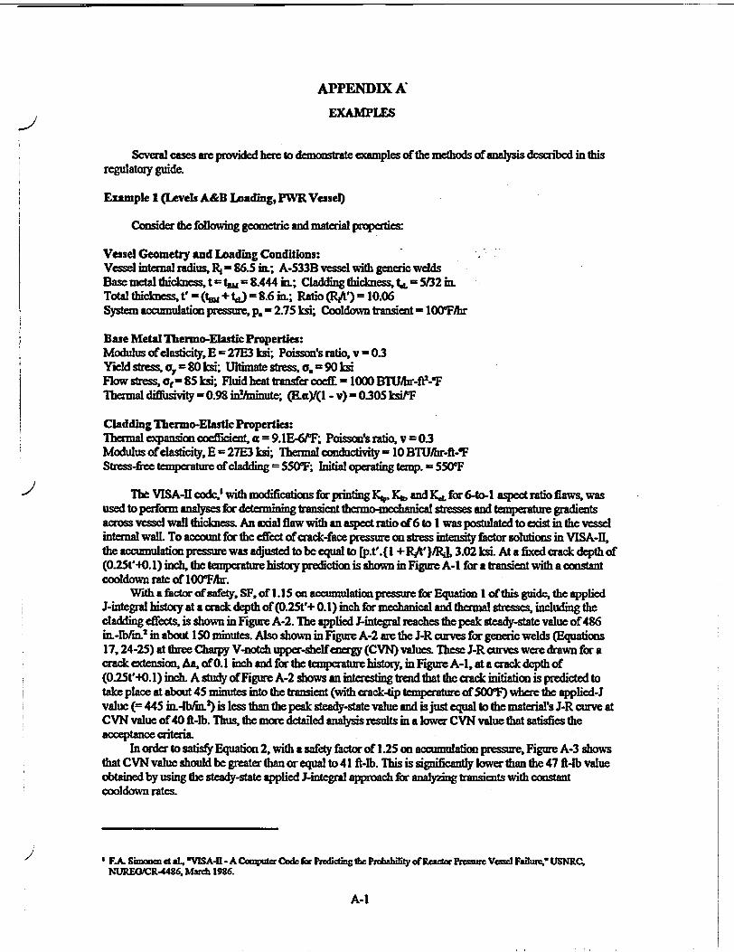
Several cases are provided hem to demonstrate examples of the methods of analysis described in this regulatory guide.
Example 1 (Levels A&B Loading, PWR Vessel)
Consider the following geometric and material properties:
Vessel Geometry and Loading Conditions: Vessel internal radius, IR = 86.5 in.; A-533B vessel with generic welds Base metal thickness, t = tam = 8.444 in.; Cladding thickness, = 5132 in. Total thicknes t' - (tm + W - 8.6 in.; Ratio (RN') - 10.06 System accumulation pressure, p. = 2.75 ksi; Cooldown transient = 10 0 Fihr
Base Metal Thermo-Elastic Properties: Modulus of elasticity, E = 27E3 ksi; Poisson's ratio, v = 0.3 Yield stress, a, - 80 ksi; Ultimate stmre, o.= 90 ksi Flow stress, ot = 85 ksi; Fluid heat transfr cocf- =1000 BTU[hr-O-'F Theral diusivity = 0.98 inninte; (E&.,Y(l - v) = 0.305kiPF
Cladding Thermo-Elastic Properties: Thermal expansion coefficient, a = 9.1E-6PF; Poisson's ratio, v = 0.3 Modulus of elasticity, E - 27E3 ksi; Thermal conductivity = 10 BTUihr-fl-¶F Stress-free temperature ofcladding = 5500F; Initial operating temp. = 550OF
The VISA-iI code,. with modifications for printing KI, Ka, and KI for 6-to-I aspect ratio flaws, was used to perform analyses for determining transient theamo-mcchanical stresses and temperature gradients across vessel wall thickness. An sxdal flaw with an aspect ratio of 6 to I was postulated to xist in the vessel internal wall. To account for the effect of crack-face pressure on stress intensity factor solutions in VISA-Il, the accumulation pressure was adjusted to be equal to [p.t'.{ l + RPA')}/, 3.02 ksi. At a fixed crack depth of (0.25t'-O. 1) inch, the tempcrature history prediction is shown in Figre A-I for a transient with a constant cooldown rate of IO0•ihr.
With a factor of safety, SF, of 1.15 on accumulation pressure for Equation I of this guide, the applied J-integral history at a crack depth of (0.25t'+ 0.1) inch for mechanical and thermal stresses, including the cladding effects, is shown in Figure A-2. The applied J-integna reaches the peak steady-state value of 486 in.-Ib/imn in about 150 minutes. Also shown in Figure A-2 are the J-R curves for generic welds (Equations 17, 24-25) at three Charpy V-notch uppcr-sheffencrgy (CVN) values. These J-R curves were drawn for a crack extnsion, As, of 0.1 inch and for the temperature history, in Figure A-I, at a crack depth of (0.25t'-O.1) inch A study ofFigure A-2 shows an interesting trend that the crack initiation is predicted to take place at about 45 minutes into the transient (with crack-tip temperature of 500F¶) where the applied-J value (-- 445 in.-lb/i. 2 ) is less than the peak steady-state value and is just equal to the material's J-R curve at CVN value of 40 ft-lb. Thus, the more detailed analysis results in a lower CVN value that satisfies the acceptance criteria.
In order to satisfy Equation 2, with a safety factor of 1.25 on accumulation pressure, Figure A-3 shows that CVN value should be greater than or equal to 41 ft-lb. This is significantly lower than the 47 fi-lb value obtained by using the steady-state applied J-integral approach for analyzing transients with constant cooldown rates.
'F.A Simoaen gt at, VISA-HI - A Computer Code for Preddting the Probabfity oafReacdr Presmer Vene F&Rlhe, USNRC. NUREOICR-4436, March 1926.
A-1

Example 2 (Levels C and D Loading, PWR Vessel)
The problem statement was presented in a meeting of the ASME Section XI Working Groups on Flaw Evaluation and Operating Plant Criteria (in Louisville, Kentucky, on December 1, 1992), where results of the analyses were compared by the participants. The vessel geometry and material properties are:
PWR vessel internal radius, R4 - 90.0 inch; A-533B plate material thickness, t = tsu - 9.0 inch; Cladding thickness, tI, = 0, Rf& = 10 Copper, Cu = 0.35wt%; Nickel, Ni = 0.3 wt%; Initial RTm. = 0.01F
Pre-irradiated CVN, - 108 R-lb (L-T orientation) Surface fluence, •t = 3.0E19 n/cm2
Flaw orientation = Axial, in plate material; Flaw aspect ratio 6 to I Fluid temperature at vessel surface, T(tm) - [550 - 25011 - exmg- 0.1 tm)W]'F with time, tin, in minutes. Heat transfer coefE = 320 BTU/br-t-OF; Thermal diffusivity = 0.98 in.2/min Elastic modulus, E = 28E3 ksi; Poisson's ratio, v =0.3; a f S&IE-6 inlm.-0F Yield stress, oy = 80 ksi; Flow stres, of-85 ksi
J-R curve: J = (SF).[CI.(Aa)c. cxpfC3.(Aa)"4] in.-kipr/ 2
where. ln(Cl) = [-2.89+1.22 ln(CVN,) - 0.0027 T + 0.014 ((t)] C2 = [0.077 + 0.116 ln(Cl)] C3 = [- 0.0812 - 0.0092 ln(Cl)] C4 --0.417 SF = 0.741 forLevelC events
The VISA-i code was used to determine thermal stress and temperature history for the Level C transient specified in the problem. It was found that at time tm = 20 minutes, the peak thermal stresses occur. The corresponding peak thermal strews intensity factor as a function of crack depth to vessel thickness ratio, a/, of semi-elliptical flaws is given as:
Kj- [21.026+374.22(a/t)-1593.56(aA)0+2912.1(a/t)-2029.7(a/)] ksih"m. with 0.05 ! at • 0.5
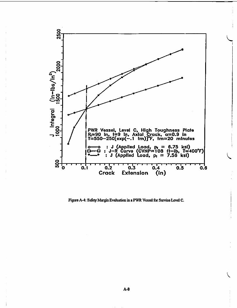
Therefore, at a = I inch, K, - 46.6 ksi-"in. At an internalpressure, p - I ksi, the pressure induced K, - 18.9 ksi-fin. Now, ifthe pressure, p, is increased, then at a pressure of 6.75 ksi, the J-applied at a = (0.It + t. + 0.1) inch becomes equal to the material's J-R curve as shown in Figure A-4. This will mark an "initiation" of ductile flaw growth. The temperature at the crack-tip (a= 0.It + t,) for time tmn= 20 minutes is 400OF. If internal pressure p is further increased, in Figure A-4 it can be seen that at pressure p = 7.56 ksi the crack growth becomes unstable. That is, the slope of the J-applied curve becomes greater than the slope of the material's J-R curve.
Example 3 (Levels C and D Loading, BWR Vessel)
The problem statement is the same as in Example 2, except for a BWR vessel geometlry. The vessel geometric details are:
BWR vessel internal radius, R. = 120.0 inch; A-533B plate material Thickness, t = t, - 6.0 in.; Cladding thickness, t., = 0, M - 20 Flaw orientation - Axial, in plate material; Flaw aspect ratio - 6 to I
The VISA-il code was used to determine thermal stress and temperature history for the Level C transient specified in the problem. It was found that at time tin =16 minutes, peak thermal stresses occur. The corresponding peak thermal stress intensity factor as a function of crack depth to vessel thickness ratio, alt, of semi-elliptical flaws is given as:
KI, = [I 2.243+227.94(at)-972.71 (aht)4+1785.2(a/t)3-1249.3(at)4] ksi"in., with 0.05 < a/t < 0.5
A-2
Therefore, at a = I inch, K -= 27.9 ksi-"in. At an internal pressure, p = I ksi, the pressure-induced K -= 37.0 ksiWin. If the pressure, p, is increased, at a pressur of4.55 ksi, the J-applied at a = (0.1 t + tL + O. I) inch becomes equal to the material's J-R curve as shown in Figure A-5, which will mark an "initiation" of ductile flaw growh The temperature at the crack tip (a-= 0.1t + t.) for time tmi= 16 minutes is 4050F. If the pressure, p, is further increased (see Figure A-5), it can be seen that at a pressure p = 4.75 ksi the crack growth has become unstable. The slope of the J-applied curve is now greater than the slope of the materials J-R curve.
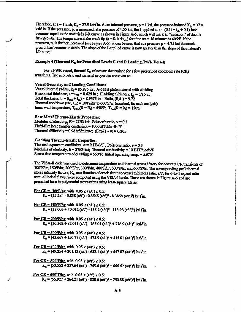
Example 4 (Thermal K1t for Prescribed Levels C and D Leading, PWR Vessel)
For a PWR vessel, thermal K3 values are determined for a few prescribed cooldown rate (CR) transients. The geometric and material properties are iven as:
Vessel Geometry and Loading Conditions: Vessel internal radius, Rý = 86.875 in.; A-533B plate material with cladding Base metal thickness, t = tm - 8.625 in.; Cladding thickness, t. = 5/16 in. Total thickness, t' = (thj + W -98.9375 in.; Ratio, W/t') = 9.72 Thermal cooldown rate, CR = 100"Fihr to 600"Fihr (constant, for each analysis) Inner wall temperature, Tk .(R - = 550'F; TsJR = R) = 150F
Base Metal Thermo-Elastic Properties: Modulus of elasticity, E = 27E3 ksi; Poisson's ratio, v = 0.3 Fluid-film heat transfer coefficient,= 1000 BTUihr-f -PF Thermal diffusivity = 0.98 in!/minute; (Ea)/(I - v) = 0.305
Cladding Thermo-Elastic Properties: Thermal expansion coefficient, a = 9.1E-61F; Poisson's ratio, v = 0.3 Modulus of elasticity, E = 27E3 ksi; Thermal conductivity- 10 BTU/hr-ft-OF Sftr -free temperature of cladding = 550-F; Initial operating temp. = 550WF
The VISA-i1 code was used to determine temperature and thermal stress history for constant CR transients of 1 00F/hr, 15( 0F/hr, 20(0Fir, 30(0F/hr, 400-F/hr, 500rFihr, and 600¶bhr. The corresponding peak thermal stress intensity factors, Y41, as a function ofcrack depth to vessel thickness ratio, aWt,, for 6-to. i aspect ratio semi-elliptical flaws, were computed using the VISA-11 code. These are shown in Figure A-6 and are presented here in polynomial expressions using least-square fits as:
For CR - 100"Fhr with 0.05 <(aft') < 0.5: Ka - [27.284 - 5.838 (aft') - 0.3548 (aft') 2 - 8.3858 (aht'Y] ksifin.
For CR - 150°F/hr, with 0.05 g (aft') s 0.5: K,4 = [32.003 + 40.012 (aft') - 138.2 (a/t'r - 113.98 (aht')r] ksif"in
For CR = 200F/hr with 0.05 < (aft') g 0.5: KI = [36.362 + 82.011 (aft') - 265.01 (aft')r + 226.9 (aft')2] ksi/rin.
For CR - 300F7hr with 0.05 : (aft') 10.5: K,4 = [43.667 + 150.77 (aft') - 474.9 (aft')2 + 415.01 (a/t')2] ksijrin.
For CR - 400°F/hr with 0.05 r. (aft') < 0.5: Kft = [49.254 + 201.12 (aft') - 632.1 (a/t'r + 557.87 (a/t')3] ksii"in.
For CR - 500OF/hr with 0.05 < (aft') < 0.5: 4 = [53.552 + 237.64 (aft') - 749.6 (aA')2 + 666.62 (aft') 3] ksarin
For CR - 600F•hr with 0.05 g (at') < 0.5: K,, = [56.927 + 264.21 (a/t') - 838.6 (aft')2 + 750.88 (aft')2] ksiv"in.
A-3

These results were also used in developing the unified Equation 13 for K, where the constant CR and the nomalizhd crack depth, at', are used as dependent vaiables. A least-square statistical fit was performed to
obtain Equation 13. The czoss-product term, (CRXa/'), was also used in developing this fit, in addition to the
polynomial terms in aW and CIL
A-4

L. 0
iz
4-
30 ..... 60 ..... 9 ..... 0 Transient Time (Minutes)
Figure A-i: Transient Tcmperatxnc H-istory at Crack Tip for Scrvce Levels A and B.
A-5
CD-
t"o
O0
an PWR Vessel, Service Levels A and 8 11R=86.5 In, t =0.156 In, t'8.6 I,. a/t*=0.25 l O0"/hr Cooldown for 150 Minutes
•o--o Temperature at the Crack-Tip 0
""150

0-.
Co
0 U)
.-D1
PWR, Level A&B, Generic Welds. t.L0. 156 In C R3,1486.5in, t'=8.6 In, Axial Crack, a/V'0.25
Io 00*F/hr Cooldown, Critical Time =45 Minutes
o---o : J (Applied Load, Criteria No. 1) Crack Extension = 0.1 In.
+-+ : J-R Curve (CVN - 41 ft-1b) O-'-- : J-R Curve (CVN - 40 ff-ib) *" * J-R Curve (CVN = 39 ft-lb)
6 . 3b 60 90 120 150 Transient Time (Minutes)
Figure A-2: J-Applied mnd J-R Curve History at Crack Tip for Service Levels A and B at a Crack Extensio of 0.1 inch.
A-6

0
C
o PWR. Level A&B, Generic Welds, f.O=.l 56 In S R=86.51n, f=8.6 In.. Axial Crack, a/t=0.25 j o00F/hr Cooldown. Critical Time =45 Minutes
o--o : J (pplied Load. Criteria No. 1) ICe---1.. J-% Curve (CVt=41 ft-lb, T=5.00TF) I ,-- .J (Applied Load, Criteria No. 2)
i . .. ... .......... ,.,,.
"0.1 " 0.2 Crack Extension
0.4 (in)
0.5 0.6
Figure A-3: Acceptable Upper-Shelf Ewrgy in a PWR Vessel for Service Levels A and B.
A-7
N CE) -o T C
4C
.0
0
|
, I ; i I
0.1 0.2 Crack
0.3 Extension
0.4 0.5 0.6 (in)
Figure A4: Safdy Margin Evaluation in a PWR Vessel for Service Lcve C.
A-S
0VUn C4
0 0
.0 CdA
T
-o
i'5
* PWR Vessel, Level C, High Toughness Plate R1=90 In, t=9 In, Axial Crack, ao0.9 In T=550-250[exp(-.1 tm)]°F, tm=20 minutes
: J (Appliled Load, pi = 6.75 ksl) "1--43 :J-R Curve (CVNP= 108 ft-lb, T=4000F)
-- : J (Applied Load, ph = 7.56 ksl)
K
K0 a a
v

0
0.2 0.3 0.4 Crack Extension (in)
Figure A-5: Safety Margin Evaluation in a BWR Vessel for Sevice Level C.
A-9

I • I.- I8 .
'C 8.93 Ii. td€. a 5/16 a..
(-60F0r.
F-50 M.
+.4 r
C
I-V). X Cý <-00 FlIV.
<-0 Fltw.
0 . . . , , ,, , , , , , ,, , , , , Tftnllfly -Ise F 0 0.2 0.3 0.4 0.5 I Normalized Crack Depth (a/f)
Figure A-6: Peak Thermal Stress Intensity Factors in a PWR Vessel for Transients with Several Different, but Constant. Cooldown Rates.
K
A-1O

"APPENDIX B
COMPUTATION OF STRESS INTENSITY FACTORS
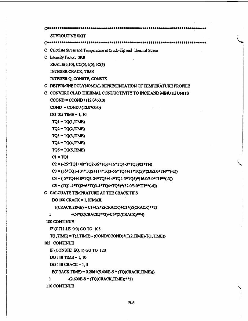
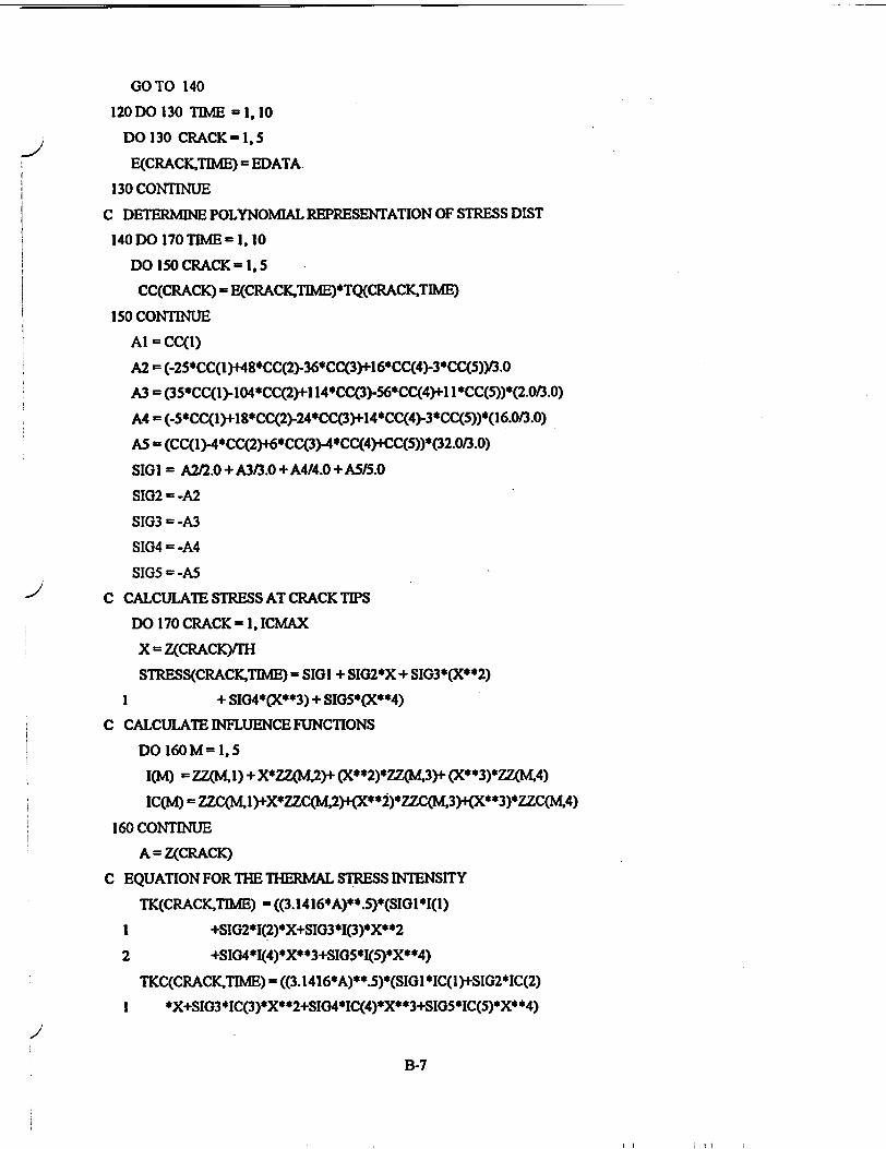
Information about computing transient temperature gradient across the vessel wall thickness, themal stresses, pressure, and thermal stress intensity factors (K.,, Kt) are provided in this Appendix as FORTRAN subroutines fiom the VISA-1 code. Additional details on the computational method, theory used, limitations, and names of the major variables used are available in NUREG/CR-4486' and NUREG/CR-3384.' The computer code provided in this Appendix is for general illustration only, to show how the cladding effects could be incorporated for thermal stresses and thermal sres intensity factors caused by differential fthemal expansion between the cladding and the base metal. i.censees should ensure that the computer codes they use include an idepth evaluation of ts effiects.
A description of cladding-iduced thermal stress intensity factors is presented in Appendix A to NUREOICR-4486. Limitations of the stress intensity factor correction factors for finite length semi-elliptical surface flaws are indicated in Appendix C to NUREG/CR-4486. In developing these correction factors, only uniform membrane and linear bending stresses were considered. In addition, the correction factors for circunfe-ential flaws were assumed to be the same as the ones for axial flaws. Improved solutions may be used on a case-by-case basis ifjustified.
'F.A Shnonen et al, *VISA-H - A Computer Code for Predicting te Probability of Reactor Pressure Vessel Failure* USNRC,
NUREG/CR-4486, March 1986. D.L Stevens et al., 'VISA- ACoemputer Code for Predicting the hbability of Reactor Pressure Vessel Failure," USNRC, NUREO/CR-33S4, September 1983. Copies are available for inspection orcopying fora fee from the NRC Public Document Roomn at 2120 L Stee NW., Washingto DC, the PDR's ai'ling address is Mail Stop U,6. Washingtm, DC 20555; telephone (202)634-3273; fax (202)634-3343. Copies ofNUREOICRs may be purchased at curent rates from e d U.S. Government Printing Office, Post Office Box 37082, Washington, DC 20013-7082 (telephone (202)512-1200); or from the Natioad Tedmical Information Service by writing NTIS at 5285 Poat Royal Road, pringd, VA 22161.
13-
I I

Taken From: VISA-H Code LNUREG/CR-4486 (1986). NUREQXR-3384 (1983)]
SUBROUTINE SPKI
Calculate PresstireValuesand, Stren Intensity Factor, PKI
DIMENSION CONST(5)
REAL 1(5). IC(5)
INTEGER CRAM TBE
C DETERMNE POLYNOMIAL REPRESENTATION OF PRESSURE
CONST(l) = PDATA(I)
CONST(2) = ((-2.5)*PDATA(I)+48*PDATA(2)-36*PDATA(3)+
I 16*PDATA(4)-3*PDATA(S))1(3*TMAX)
CONST(3) = (35*PDATA(l)-104*PDATA(2)+114*PDATA(3)
I 56*PDATA(4)fI I *PDATA(5))*V(3*TMX**2)
CONST(4) = ((-5)*PDATA(])+18*PDATAC2)-24*PDATA(3)+
I 14*PDATA(4)-3*PDATA(5))*161(3*TMAX**3)
CONST(5) = (PDATA(l)-4*PDATA(2)+6*PDATA(3)-4*PDATA(4)+
I PDATA(5))*32/(3*TMAX**4)
C Calculate PRESSURE Component of Applied K, PKI, For Each 1-kne Crack Depth
OUTRAD=RAD+TH
FACTOR = RAD**2.0 / (OUTRAD**2.0 - RAD**2.0)
C
DO 120 TAM = 1, 10
IT = TMAX*TflvWI0.0
DOI 10 CRACK= 1, 1CMAX
X=Z(CRACKYM
C CALCULATE INFLUENCE COEFFICIENTS
DO 100M= 1,5
IM =ZZ(Kl)+X*ZZOA.2)+(X**2)*ZZ(K3)+(X**3)*72XK4)
IC(M) - ZZC(MI) + X*ZZC(K2) + (X**2)*ZZC043) + (X**3)*ZZC(K4)
100 CONTINU13
PRES(TDAE) = CONST(I)+CONST(2)*TT+CONST(3)*TT**2+CONST(4)*TT*
I *3+CONST(5)*TT**4
PKI(CRACK.TIME) = PRESCrB4E)*((3.1416*Z(CRACK))**.5)*(10.5238*1(1)
I -1.1524*I(-2)*X40.1729*1(3)*(X**2)-0.0230*1(4)
2 *(X**3)+0.0029*1(5)*(X**4))
B-2

PKIC(CRACK,TIMfE) = 5*pREs(TIME)((3. 1416*Z(CRACK))**.5)*1C(I)
RATIO = RAD / (1O.0*5 TH)
PKI(CRACK.TIME) - RATIO * PKI(CRACKTIME)
PKIC(CRACK,TIME) = RATIO * PKIC(CRACK.TIME)
c CALCULATE HOOP STRESS
SHOOP(CRACKTIE) = FACTORS* PRES(TME)
1 (1.0 + (OUTRAD/CRAD + Z(CRACK)))**2.0)
110 CONTINUE
C CALCULATE LONGITUDINAL STRESS
SLONCTCITIME) = PRES(TIME) *FACTOR
120 CONTINUE
RETUR}N
END
SUBROUTINE TPOLY
C CALCULATE WATER TEMPERATURES USING A POLYNOMIAL' MODEL
REAL TEMP(5), CONST(5), S(5). AN(4). Y(4,5). KTEST
REAL K, KO, CP(4), SUM(4)
INTEGER TIME, CRACK. CONSTK CONSTE
INTEGER Q C KPOLYNOMIAL Modeling of The Wate Temperature
C Determine Meta Temperature For EACH CRACK DEPTH AND TIME INTERVAL
DO 100N= 1,5
TEMP(N) - TDATA(N) - TINT
100 CONTINUE
C FIT A 'POLYNOMIAL TO THE WATER TEMERATURE
CONST(1) = TEMP(1)
CONsT(2) - ((..25)*TEMP(1) + 48*TEMP(2) - 36*TEMP(3) +
1 16*TEMP(4) - 3*TEM[P(5WY(3*TMAI)
CONST(3) - (35*TEMOP(1) - 1O4*TEMP(2) +11 4*TEMP(3)
I 56*TEMP(4) + I I *TEhe(5))*2/(3*TMAX**2)
CONST(4) = ((-5)*TEMP() + 18*TEMP(2) -24*TEMP(3) +
1 14*TEMP(4) - 3*TEMP(5)Y'16/(3*TMAX**3)
CONST(5) = (TEMP(1) - 4*TEMP(2) + 6*TEMP(3) - 4*TEMP(4) +
I TEIP(5))*32I(3*TMAX**4)
DO 150 TIME =1. 10
B-3

"TT = TMAX*TIMFJIO.
C EQUATION FOR THE TEMPERATURE OF THE WATER
TWATER(TIME) = TINT+CONST(I)+ CONST(2)*TT + CONST(3)*TT**2 +
1 CONST(4)*TT**3 + CONST(5)*TT**4
DO 150 CRACK= 1,5
K=KO
I1O X = ZQ(CRACK)/TM
TAU - K*TTfTH**2
DO 120M= 1, 5
W(M) = CONST(M) *
120 CONTINUE
DO 130N- 1,4
ALNQ - AL(NQ)
AN(N) = 2 * SIN(ALNQ)/(ALNQ + SIN(ALNQ)* COS(ALNQ))
CP(N) = COS(ALNQ (I-X))
Y(N,I) -I - EXP(-(ALNQ**2)*TAU)
DO 130 M -2, 5
Y(NM) = TAU**(M-I) - (Y (NM-IyALNQ**2)*(M-1)
130 CONTINUE
DO 140N= 1,4 ,
ALNQ - AL(NQ)
SUM(N) - AN(N) * CP(N) * (S(I) * EXP(-(ALNQ**2*TAU)) + S(2)
I * Y(N,IYALNQ**2 +2*S(3)* Y(N,2)ALNQ**2 + 3 *S(4) * Y(N,3)
2 /ALNQ**2 +4 *S(5)*Y(N,4)/ALNQ**2)
140 CONTINUE
C EQUATION FOR THE QUARTER POINT TEMPERATURES
TQ(CRACK,TIME) - TWATER(TIME) - SUM(I) - SUM(2) - SUM(3) - SUM(4)
C CONTROL FOR THE CONSTANT KAPPA OPTION
IF (CONSTK-.EQ. 1) GO TO 150
C TESTFOR THE ACCURACY OF KAPPA FOR THE GIVEN METAL TEMPERATURE,
C IF THE DESIRED ACCURACY IS NOT OBTAINED, ITERATE ON KAPPA
C FOR THIS CRACK DEPTH AND TIME.
KTEST = 1.030 - (5.97E-7)*((T(CRACKTIME))**2)
IF ((ABS(KTEST-K)) JLE. 0.0001) GO TO 150
K=KIEST
GOTO 110
150 CONTINUE
B-4

RETURN
END
SUBROUTINE TEXP
C Calculate WATER TEMPERATURES Using an 'Exponential Decay" Model
REAL B. KTEST, K, KO. SUM(4)
INTEGER CRACK, TIME, CONSTK, CONSTE
INTEGER Q
C EXPONENTIAL DECAY MODEL OF THE WATER TEMPERATURE
DO 130 TIME = 1, 10
TT = TMAX*TIMFl0.
C EQUATION FOR THE TEMPERATURE OF WATER
TWATER(TIME) = TO + DT * (I-EXP(-BE*TT))
DO 130 CRACK i 1,5
K=KO
100 WSQ = BE*TH*THK
TAU - K*TT/(TH*TH)
DO 120N=1,4
ALNQ = AL(N.Q)
B = -DT*((2*SIN(ALNQ)/(ALNQ+(SIN(ALNQ))*(COS(ALNQ))))
I *(EXP(-(ALNQ**2*TAU))-EXP(-WSQ*TAU))I((ALNQ**2/WSQ)-1))
X =i ZQ(CRACKYTH
SUM(N) = B * COS(ALNQ*(I -X))
120 CONTINUE
C EQUATON FOR THE -QUARTER POINTS" TEMPERATURE VALUES
TQ(CRACKTIME) = TWATER(TIME) - SUM(1) - SUM(2) - SUM(3) - SUM(4)
C CONTROL FOR THE CONSTANT KAPPA OPTION
IF (CONSTK.EQ. 1) GO TO 130
C TEST FOR KAPPA ACCURACY AND CONTROL OF KAPPA OPTION
KTEST = 1.030 - (5.97E-7)*((T(CRACKTIvE))**2)
IF ((ABS(KTEST-K)) IE. 0.0001) GO TO 130
K =KTEST
GO TO 100
130 CONTINUE
RETURN
END
B-5
,I i ,
SUBROUTINE SKIT
C Calculate Stress and Temperature at Crack-Tip and Thermal Stress
C Intensity Factor, SKIt
REAL E(5,10), CC(5), I(5), IC(5)
INTEGER CRACK, TIME
INTEGER Q, CONSTE, CONSTK
C DETERMIINE POLYNOMIAL REPRESENTATION OF TEMPERATURE PROFILE
C CONVERT CLAD TIHERMAL CONDUCTIVITY TO INCH AND MINUTE UNITS
CCOND = CCOND / (12.0*60.0)
COND = COND /(12.0*60.0)
DO 105 TIME - 1, 10
TQI = TQ(I.TIME)
TQ2 - TQ(2,TIME)
TQ3 - TQ(3,TIME)
TQ4 = TQ(4.TIME)
TQ5 = TQ(5,TIME)
Cl =TQI
C2 = (-25*TQI+48*TQ2-36*TQ3+16*TQ4-3*TQS)/(3*TH)
C3 = (35*TQI-104*TQ2+114*TQ3-56*TQ4+1 I *TQS)*(2.0/3.0*TH**(-2))
C4 = (-5*TQI+1 S*TQ2-24*TQ3+14*TQ4-3*TQS)*(16.03.0*TH**(-3))
C5 = (TQI-4*TQ2+6*TQ3-4*TQ4+TQ5)*(32.0/3.0*TH**(-4))
C CALCUATE TEMPRATURE AT THE CRACK TIPS
DO 100 CRACK = 1, ICMAX
T(CRACKTIME) = C1+C2*Z(CRACK)+C3*(Z(CRACK)**2)
I -C4*(Z(CRACK)**3)+C5*(Z(CRACK)**4)
100 CONTINUE
IF (CTH .LE. 0.0) GO TO 105
T(,TIME) = T(2,TIME) - (COND/CCOND)*(r(2,TIME)-T(ITME))
105 CONTINUE
IF (CONSTE .EQ. 1) GO TO 120
DO 10 TIME = 1, 10
DO 110 CRACK = 1,5
E(CRACKTIME) = 0.286+(5.400E-5 * (TQ(CRACK,TIMED)))
1 -(2.600E-8 * (TQ(CRACK,TIME))**2)
110 CONTINUE
B-6
K
K
GO TO 140
120 DO 130 TIME = 1.10
DO 130 CRACK - 1, 5
E(CRACK,TIME) - EDATA
130 CONTINUE
C DETERMIN POLYNOMIAL REPRESENTATION OF STRESS DIST
140 DO 170 TIME - 1, 10
DO 150 CRACK - 1, 5
CC(CRACK) - E(CRACKTIMAE)*TQ(CRACK.TIIE
150 CONTINUE
Al =CCWI
A2 - (-25*CC(1)48*CC(2)-36*CC(3)+16*CC(4)-3*CC(5)Yt3.0
A3- (35*CC(1)d104*CCC)+1 14*CC(3)-56*CC(4)+1 1 *CC(5))*(2.0/3 0)
A4 = (-5*CC(1)+18*CC(2)-24*CC(3)+14*CC(4)-3*CC(5))*(16.0I3.0)
A5 - (CC(l)-4*CC(2)+6*CC(3)-4*CC(4)+CC(5))*(32.0I3.0)
SIG) = AMf.0 + A3/3.0 + A414.0 + A5/5.0
SIG2 =-A2
SIG3 = -A3
SIG4 = -A4
IGS = -A5
C CALCULATE STRESS AT CRACK TIPS
DO 170 CRACK - 1. ICMAX
X =Z(CRACK)/TH
STRESS(CRACK,TIME) - SlGI + S102*X + SIG3*(X**2)
I + SIG4*(X**3) + SIGS*(X**4)
C CALCULATE INFLUENCE FUNCTIONS
DO 160M= 1,5
I(M = ZZ(M1) +X*ZZ(M,2)+ (X**2)*ZZQM.43)+ (X**3)*ZZ(M.4)
IC(M) =ZZC(Mj)+X*ZZC(M2)4(X**2)*ZZC(MK3)+(X**3)*ZZC(MA)
160 CONTINUE
A = Z(CRACK)
C EQUATION FOR THE THERMAL STRESS INTENSITY
TK(CRACKTIE) - ((3.1416*A)**.5)*(SIGI 1(1)
I +51G2*I(2)*X+SIG3*I(3)*X**2
2 +SIG4*IK4)*X**3+SI050I(5)*X**4)
TKC(CRACK,TilvE) =(3. 141 6A)**.5)*(SIO1 *IC(1)+SIG2*IC(2)
I *X+51G3*IC(3)*X**2+5104*IC(4)*X**3+5105*IC(5)*X**4)
B-7
. I I I

170 CONTINUE
RETURN
END
SUBROUTINE KICLAD
C THIS SUBROUTINE CALCULATES STRESSES AND STRESS INTENSITY FACTORS
C DUE TO THE PRESENCE OF "CLADDING" ON THE I.D. SURFACE OF THE VESSEL
INTEGER CRACK, TIME
INTEGER CONSTE, CONSTK, Q
REAL 10, 11
DO 170 TIME- I, 10
C CALCULATE STRESS DISTRIBUTION THROUGH VESSEL WALL
C TEMP AT CLAD/BASE METAL INTERFACE
TI = 0.5*(T(2,TIME) + T(3,TIME))
C TEMPERATURE AT THE VESSEL I.D.
TO - T(,TIME)
C STRESS-FREE TEMPERATURE
TI= SFREET
C CALCULATE STRESS DISTRIBUTION DUE TO CLAD K C SIGCI = STRESS IN CLAD AT VESSEL I.D.
C SIGC2 = STRESS IN CLAD AT CLAD/BASE METAL INTERFACE
C SIGBI = STRESS IN BASE METAL AT CLAD/BASE METAL INTERFACE
C SIGB2 - STRESS IN BASE METAL AT VESSEL O.D.
DELEA - CLADE*CALPHA*(I-ARATIO)/(I-CLADNU)
C CALCULATE STRESS IN CLAD (KSI)
SIGCI - DELEA* (TI - TO)
SIGC2 = DELEA ( -TI)
C CALCULATE FORCE DEVELOPED IN CLAD
FCLAD = CTH*0.5*(SIGCI + SIGC2)
C CALCULATE STRESSES IN BASE METAL (KSI)
RO -RAD
RI = RAD +CTH
R2 =RAD+TH
CONST = 1.0/((R2/RI) 2.0-1.0)*(RO-RI)/RI *DELEA
I *(TI-O.5*(TO+TI))
SIGBI = CONST * (I + (R2/RI)**2.0)
B-8

SIGB2 - CONST * 2.0
C CALCULATE FORCE DEVELOPED IN BASE M[ETAL
FBASE - (CTH-TH*0.S*(SIGBI+SIGB2)
C ADJUST SIGB 1 AND'SIGB2 TO BALANCE FORCES FCLAD AND FBASE
SIGINC - 0.5*(SIGBI-SIGB2)
SIGAVE -0.5*(SIGBI+SIGB2)*FCLAD/FBASE
SlOB 1 - SIGAVE + SIGINC
SIGB2 - SIGAVE - SIGINC
C CALCULATE CONSTANTS DESCRIB3ING STRESS DISTRIB3UTION
C QI - SLOPE OF CLAD STRESS DISTR.
QI - (SIGCI-SIGC2)/SIGC1/(CTHITH
C P -SLOPE OF BASE METAL STRESS DISTR.
P = (SIGB2-SIGB1Y/SIGCJC/ I((IH-CTHYMH
C -R -INTERCEPT OF BASE METAL STRESS GRAD. AT VESSEL L.D.
R-=-(SIOBMI/SIO - P*CTWFH)
C CALCULATE STRESS AND KI DUE TO CLAD FOR ALL Z(CRACK'S,
C KI AT THE L.D. SURFACE EQUALS ZERO (LE.,CRACKDEPTH = ZERO)
SCLAD(1,TJME) - SIOCI
CLADK(1,TIME) = 0.0
C KIlIN CLAD NEAR CLAD/BASE METAL INTERFACE
SCLAD(2,TDME) = SIGC2
ALP = Z(2)/TH
10 = 1. l22+0.9513*ALP-0.624*ALP**2.0+8.3306*ALP**3.0
Il = 0.6825+0.3704*ALP-O.0832*ALP**2.O+2.8251 *ALP* $3.0
CLADK(2,TIME) - SQRT(3. 14159*Z(2))*SIGC1 *(IO-QI*ALP*I1)
C CALCULATE KI IN BASE M[ETAL
XI= CTH/TH
DO 170 CRACK = 3,35
ALP - Z(CRACK)/T
SCLAD(CRACKTIME) = (-R+ALP*P)*SIGCI
10 - 1. 1 2240.9513*ALP-0.624*ALP**2.0+8.3306*ALP**3.0
CLADK(CRACK,TIMvE) - SQRT(3. 14159*Z(CRACK))*SIGC1 *1.751938
I *((IO-0.63662)*((1 .0+R)*ASINQUI/ALP)+ALP*((QI+R*P)
2 *SQRT(1 QWXALP)**2.)-QI)-1 .570796*R)+(IO01 .0)*(((1 .0+R)-XYt.
3 *(QI+R*P))*SQRT(1 .- (XALP)**2.)+ALPt2.0*(QI+R*P)*ASIN(XIIALP)
4 -1 .0-0.7894*R*P*ALP))
170 CONTINUE
B-9
I I
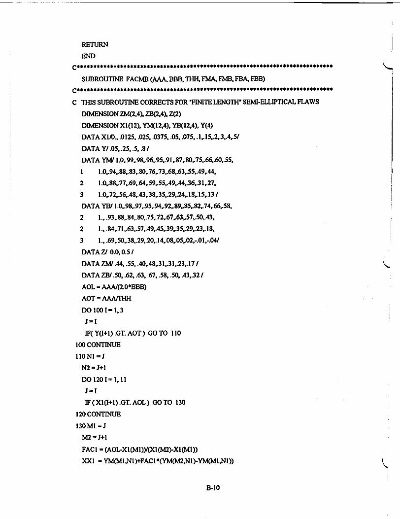
RETURN
END
SUBROUTINE FACMB (AAA, BBB, THH, FMA, FMB, FBA, FBB)
C THIS SUBROUTINE CORRECTS FOR *FINITE LENGTH" SEMI-ELLIPTICAL FLAWS
DIMENSION ZM(2,4), ZB(2,4), Z(2)
DIMENSION X1(12), YM(12,4), YB(12,4), Y(4)
DATA XI/O., .0125, .025, .0375, .05, .075,.l,.15,.2,.3,.4,5I
DATA Y/.05, .25, .5, .8 /
DATA YM/ 1.0,.99,.98,.96,.95,.91,.87,.80,.75,.66,.60,.55,
1 1.0,.94,.88,.83,.80,.76,.73,.68,.63,.55,49,.44,
2 1 .0,.88,.77,.69,.64,.59,.55,.49,.44,36,31,.27,
3 1.0,.72,.56,.48,.43,.38,.35,.29,.24,. 18,.15,.131
DATA YB/ i.0,98,97,.95,.94,.92,.89,85,.82,74,.66,.58,
2 1., .93,.88,.84,.80,.75,.72,.67,.63,.57,.50,.43,
2 1., .84,.71 ,.63,.57,.49,.45,.39,.35,.29,.23,.18,
3 1., .69,.50,.38,.29,.20,.14,.08,.05,.02,-.01,-.041
DATA Z/ 0.0, 0.5 /
DATA ZM/.44,.55, .40,.48,.31,.31,.23,.17 I
DATA ZB/.50, .62, .63, .67, .58, .50, .43,.32 I
AOL = AAAI(2.0*BBB)
AOT = AAAfTHH
DO 100- I=1,3
J=I
IF(Y(I+1).GT.AOT) GO TO 110
100 CONTINUE
liONI =J
N2 =J+l
DO 1201= 1, 11
J=I
IF(XI(I+1).GT.AOL) GOTO 130
120 CONTINUE
130 MI =J
M2 = J+l
FACI = (AOL-XI(M1))/(Xl(M2)-XI(M1))
XXI = YM(MI ,N1)+FAC I *(YM(M2,NI)-YM(MI,N1))
B-10

MU =YM(MIN2)+FACI*(YM(M2,N2)-YM(MI.N2))
FAC =(AOT-Y(NI)Y(Y(N2)-Y(Nl))
IF (AOT IT. 0.05 ) FAC 0.0
F (AOT.GT. 0.80) FAC 1.0
FMA = XXI + FAC*(XX2 - XXI
XXI = YB(MINl) + FACI*(YB(tMNl)-YB(MINl))
xm -YB(miN2)+FACI*(YB(tMN2)-YB(MI.N2))
IFBA - XXI + FAC*(XM - XXI
FAC I = AOL/0-5
XXI -ZKI.Nl)+FACI*(U4C2,Nl)-ZM(INl))
)m =zm(iN2)+FACI*(ZM(2,N2)-ZM(l.N2))
FMB = XXI + FAC*(3M-XXI)
XXI - ZB(INl) + FACI*(ZB(2,Nl)- ZB(INl))
XM = ZB(IN2) +FACI*(ZB<2.N2)- ZB(I.N2))
FBB - XXI + FAC*(XM -XXI)
RETURN
END
B-11

REGULATORY ANALYSIS
1. STATEMENT OF THE PROBLEM
Appendix 0, 'Fracur Toughness Requircmencs,' to 10 CFR Part 50, 'Domestic Licensing of Production and Utilization Facilities,' requires, in part, that the reactor vessel bcltline materials '... must have Charpy upper-shelf energy of no less than 75 ft-lb (102J) initia"ly and must maintain uppcer-shelf energy throughout the life of the vessel of no less than 50 ft-lb (68J). unless it is demonstrated in a manner approved by the Director, Office of Nuclear Reactor Regulation, that lower values of upper-shcfenergy will provide margins of safety against fracture equivalent to those required by Appendix ofothe ASME Code." This Regulatoxy Guide 1.161, 'Evaluation of Reactor Prcssure Vessels with Charpy Upper-Shelf
Ener-y Less Than 50 ft-lb,' has been developed to provide acceptance criteria and analysis methods acceptable to the NRC staff for demonstrating margins equivalent to those in Appendix 0 to Section III of the ASME Code.
Publication ofrgulatcry guidance was undertaken because no comprehensive guidance currently exists, and there are reactors, both pressurized water reactors and boiling water reactors, with upper-shelf energy that is projected to fall below the 50 ft-lb regulatory limit before the end of the current license period. Withut comprehensive regulatory guidance. each affected licensee will have to submit a plant-specific analysis, including acceptance criteria and evaluation methods, and the staffwill have to evaluate each submittal without the benefit of staed acceptance criteria and approved evaluation methods.
2. OBJECTIVES
The objective of this guide is to provide acceptance criteria and evaluation methods acceptable to the NRC staff for demonstrating margins equivalent to those in Appendix 0 to Section MI of the ASME Code for those beltline materials whose Charpy upper-shelf energy falls below the regulatory limit provided in Appendix 0 to 10 CFR Part 50.
3. ALTERNATIVES
Two alternatives to issuing evaluation procedures for pressure vessels with Charpy upper-shelf energy less than 50 ft-lb were considered: (1) endorse actions being implemented by Section X[ of the ASME Code and (2) take no action.
3.1 Endone ASME Code, Section XI, Appendix K
The ASME, in Section X)M has published Appendix K' that provides acceptance criteria and evaluation procedures for pressure vessels with Charpy upper-shclf energy less than 50 ft-lb. However, the Appendix K evaluation procedures curently address only Service Levels A and B, and no guidance on specific materials properties is provided. It is important that all four service levels be considered in the evaluations, and it is important that specific guidance on estimating material properties be provided. Given the ASME codification process, and the process whereby the NRC endorses ASME appendices and code cases, the time delay in obtaining suitable guidance would be excessive. At present, the ASME's Appendix K does not provide complete guidance. As discussed above, Appendix K does not provide information on the selection of transients, and it gives very little detail on the selection of material properties. As such, a request for revision of Appendix K to Section XM of the ASME Code will have to be made.
3.2 Take No Action
As discussed in SECY-93-048,2 'Status of Reactor Pressure Vessel Issues Including Compliance With 10 CFR Part 50, Appendices 0 and IV, using the NRC staffs generic criteria for estimating Charpy upper-shelf energy, there are currently 15 plants that would have calculated upper-shelf energy less than 50 ft-lb and 3 others that would haveuppcr-shelf energy below 50 ft-lb before the end of their operating licenses. Appendix 0 to 10 CFR Part 50 requires that licensees submit
,A.npdxK emously, Code Caw N-•S 12), "Asesment cef tor Vessels with low Upper ShelfCmpy kmpact Er"y ls,' Amrica Society of Mechanical Engineers, Section Xn 1993.
2 Jcmes MK Taylor, Executive Director for Opcrat, SECY-93-04, Policy Issue (Infamtloo) for the Connissionae, USNRC Fchuay 25, 199. ics am~ ava'lable fr"or m eorpying f a fee =fr9= NRC Public Document Room at 2120 L Sret NW., Washington, DC; 1he PDR's maiing
address is Mail Stop LL.6, Washgto. DC 20555; telephone (202)634-3273; fax (202)634-3343.
R-1

analyses to demonstrate margins equivalent to those in Appendix G to Section MI of the ASME Code 3 years before the upper-shelf energy of any beitline materials falls below 50 ft-lb. Therefore, taking no action is not a viable alternative.
4. COSTS AND BENEFITS OF ALTERNATIVES
The cost and benefits of the two alternatives discussed above are presented here.
4.1 Endorse Appendix K to ASME Code Section XI
The acceptance criteria proposed in Appendix K to ASME Section XI are identical to those proposed in this regulatory guide. The regulatory guide analysis procedures for Service Levels A and B were taken from Appendix K. However, the guide provides procedures applicable to Service Levels C and D. The regulatory guide provides specific guidance on appropriate material properties and on selection of transients for consideration, whereas Appendix K does not provide these procedures and guidance. Without this guidance, each affected licensee would have to develop appropriate procedures for Service Levels C and D, justify the choice of transients, and develop plant-specific material properties.
It is estimated that without the guidance of this regulatory guide, developing plant-specific procedutes and material Upopties and applying them to check and report the analysis results would require an additional 6 staff-months (1040 hours)
for each affected licensee. Assuming that half of the affected licensees either belong to owners! groups or could make use ofcoimon data, the total additional burden on the licensees that would be incurred by plant-specific analyses is estimated as 9 plants x 6 staff-months per plant, or 54 staff-months (9360 hours).
In addition to the increased burden on the licensees, it is estimated that an additional 1.5 NRC staff-month would be required to review each plant-specific submittal. Thus, the total increased burden on the NRC staff assuming that half of the affected plants can be grouped, is estimated to be 9 plants x 1.5 staff-month per plant, or 13.5 staff-months (2340 hours). This estimate assumes that there would be only minor discussions with the licensees.
4.2 Take No Action
As discussed in Section 3.2 above, taking no action is judged to be a nonviable alternative.
5. DECISION RATIONALE K
It is rehmnded tat the reglatory guide be issued because it would offer a comprehensive set of acceptance criteria, evaluation procedures, and material properties that can be used to perform the analyses required under Appendix 0 to 10 CFR Part 50 for those pressum vessels that have Charpy upper-shelf energy of any beltline material that falls below 50 ft-lb. Issuing the regulatory guide is recommended over the alternative of endorsing Appendix K to ASME Section XI because Appendix K does not currently include (1) analysis procedures for Service Levels C and D, (2) guidance on selecting the transients for evaluation, or (3) details on tempesture-dependent material properties. Further, it is estimated that preparing plant-specific analyses that include the procedures and data that are not addressed in Appendix K would require approximately 54 staff-months of effort for the industry and approximately 9 staff-months for the NRC to review the additional information.
The NRC staff considered the possibility of worling with the ASME Code Section XI working group to modify Appendix K to include the missing procedures and data. However, given the number of plants that could need the guidance in the near term, and given the ASME codification process and the NRC's process for endorsing ASME documents, the time needed to modify and endorse Appendix K was judged to be excessive,.
The efficacy cdw procedures in the regulatory guide was demonstrated by generic bounding calculations3 performed by the NRC staff in preparing SECY-93-048. These calculations demonstrated that the requirement in Appendix 0 to 10 CFR Part 50 to demonstrate margins equivalent to those in Appendix O to Section Ill to the ASME Code could be satisfied for materials with Charpy upper-shelf energy less than 50 ft-lb for all the generic vessel geometries and material combinations considered.
3 Charles Z. Seapan. Jr., NRC, Memorandum to Jack Stunider, NRC, January 15, 1993, "Generic Bounding Analyses for Evaluation of Low Charpy UperýME .ffeon Safety Margi Against Fracture of RPV Beltine Plate and Weld Materials', Charles Z. Serpan Jr.. NRC. Memorandum to Jack Strmider, NRC, Fdxuay s, 1993, "Additional hrmation Regarding Results of Generic Bounding Analyses for Evaluation of Pressure Vessels Fabrcated Using Low ChaW Uppr-Shelf Energy Materials." Copies are available for inspection or copying for a fee firom the NRC Public Document Room at 2120 L Street NW., Washington, DQ, the PDR's mailing a is Mail Stop .L6. Washington. DC 20555; telepo (202)634-3273; fax (202)634-3343.
R-2

The regulatory guide acce-,.snce criteria were taken directly from the ASME efforts. The criteria were developed by the ASME Code Section XI working group over an I I-year period and represent the collective judgment of a body of cxerts representing the NRC stafl research contractors, nuclear utilities, nuclear power plant vendors, consultants, and
S academia. Similarly, the evaluation procedures for Service Levels A and B were developed by this group. The procedures in the regulatory guide for Service Levels A and B are essentially identical to those in Appendix K to ASME Section 3. Thus, the aoceptance criteria and die evaluation procedures for thc service levels that generally control the analyses are based on the consensus technical 6pinion of a large group of technical cxpes and were developed over an extended period.
The evaluation procedures for Service Levels C and D were developed by the staff and build on the procedures for Service Levels A and B. As part of a continuing effort by die ASME Section XI working group, the NRC staff has compared 1he regulatory guide procedures to odr procedures that are being developed by various organizaticns. The comparison was very favorbl; with the procedures proposed in the regulatory guide predicting lower acceptable Charpy upper-shelf energy values than would be predicted by the other procedures, which were less rigorous and, consequently, more conservative.
The procedures for transient selection are based on procedures that have already been endorsed by the star Alternatively, generic bounding transients can be used ifjustified.
The guidance on material properties is based on a state-of-the-art statistical evaluation of all available fracture touglmess data. A broad range of alternatives is offered in the regulatory guide so that methods acceptable to the staff arc offered for virtually every siuation and combination of circumstances.
The regulatory guidc provides timely, cost-effectivc guidance that is based on the consensus of a lar group of tecdincal experts represnting divers• badcgmrmds and nerecst The specific guidance is comprehensive and would provide an effective and definitive approach to performing equivalent margin anaiyscs.
'N L
PR ein
g r
J n meycled~
Federal Recycling Program
R-3

}
UNITED STATES NUCLEAR REGULATORY COMMISSION
WASHINGTON, D.C. 20555-0001
FIRST CLASS MAIL POSTAGE AND FEES PAID
USNRC PERMIT NO. G-67
OFFICIAL BUSINESS PENALTY FOR PRIVATE USE, $300
/