
Regulations concerning construction and supervision · PDF fileRegulations concerning...
45
1 Regulations concerning construction and supervision of smaller cargo ships Legal basis: Laid down by the Norwegian Maritime Authority on dd. mm 2013 pursuant to the Act of 16 February 2007 No. 9 relating to Ship safety and Security (Ship Safety and Security Act) sections 2 third paragraph, 6, 9, 11, 12 first and second paragraph, 13, 21, 41 third paragraph, 43 fifth paragraph, 45 and 47, cf. Royal Decree of 16 February 2007 No. 171 and the Ministry of Trade and Industry's Formal Delegation of 31 May 2007 No. 590. EEA references: The EEA Agreement, Annex II, chapter XIX point 1 (Directive 98/34/EC amended by Directive 98/48/EC). Chapter 1 General Section 1 Scope of application (1) These Regulations shall apply to Norwegian cargo ships of 8 metres and above in overall length, but below 24 metres in length (L). (2) For the purpose of these Regulations, cargo ship shall mean a ship which is not: a) passenger ship; b) fishing vessel; c) barge; or d) auxiliary vessel operating together with its parent ship. (3) Passenger ship shall mean a ship certified to carry passengers or a ship which is covered by the scope of application of the Regulation of 24 November 2009 No. 1400 concerning the operation of vessels carrying 12 passengers or less, etc., and which is engaged only in activities described therein. Section 2 Existing ships (1) Cargo ships the keel of which was laid before 1 January 2014 shall comply with the provisions of the Norwegian Regulations applicable at the time of the construction of the ship. In addition later amendments applicable to cargo ships the keel of which was laid before 1 January 2014 shall apply, as laid down in Regulations previously in force, and in chapter 13 of these Regulations. (2) The Norwegian Maritime Authority may order that the ship wholly or partly shall comply with newer provisions than the provisions in force at the time the keel of the ship was laid, in the event of: a) modifications in the use or operation; b) replacement of equipment; c) repairs, conversions; d) increased draught; or for other reasons, after a specific assessment of safety based on the general structural design, equipment, arrangement and condition of the ship. Section 3 Equipment voluntarily installed on board Equipment which is voluntarily installed on board shall comply with the provisions of these Regulations.
Transcript of Regulations concerning construction and supervision · PDF fileRegulations concerning...

1
Regulations concerning construction and supervision of
smaller cargo ships
Legal basis: Laid down by the Norwegian Maritime Authority on dd. mm 2013 pursuant to the Act of 16 February 2007 No.
9 relating to Ship safety and Security (Ship Safety and Security Act) sections 2 third paragraph, 6, 9, 11, 12 first and second
paragraph, 13, 21, 41 third paragraph, 43 fifth paragraph, 45 and 47, cf. Royal Decree of 16 February 2007 No. 171 and the
Ministry of Trade and Industry's Formal Delegation of 31 May 2007 No. 590.
EEA references: The EEA Agreement, Annex II, chapter XIX point 1 (Directive 98/34/EC amended by Directive 98/48/EC).
Chapter 1 General
Section 1 Scope of application
(1) These Regulations shall apply to Norwegian cargo ships of 8 metres and above in overall length,
but below 24 metres in length (L).
(2) For the purpose of these Regulations, cargo ship shall mean a ship which is not:
a) passenger ship;
b) fishing vessel;
c) barge; or
d) auxiliary vessel operating together with its parent ship.
(3) Passenger ship shall mean a ship certified to carry passengers or a ship which is covered by the
scope of application of the Regulation of 24 November 2009 No. 1400 concerning the operation of
vessels carrying 12 passengers or less, etc., and which is engaged only in activities described therein.
Section 2 Existing ships
(1) Cargo ships the keel of which was laid before 1 January 2014 shall comply with the provisions of
the Norwegian Regulations applicable at the time of the construction of the ship. In addition later
amendments applicable to cargo ships the keel of which was laid before 1 January 2014 shall apply,
as laid down in Regulations previously in force, and in chapter 13 of these Regulations.
(2) The Norwegian Maritime Authority may order that the ship wholly or partly shall comply with
newer provisions than the provisions in force at the time the keel of the ship was laid, in the event of:
a) modifications in the use or operation;
b) replacement of equipment;
c) repairs, conversions;
d) increased draught;
or for other reasons, after a specific assessment of safety based on the general structural design,
equipment, arrangement and condition of the ship.
Section 3 Equipment voluntarily installed on board
Equipment which is voluntarily installed on board shall comply with the provisions of these
Regulations.

2
Chapter 2 Construction and strength
Section 4 Construction standards
(1) Vessels of less than 15 metres in overall length shall be constructed, dimensioned and equipped
in accordance with one of the following standards:
a) Nordic Boat Standard for Commercial Boats less than 15 metres, 1990;
b) DNV's standard for certification No. 2.21 Craft April 2010.
(2) Vessels of 15 metres and above in overall length shall be constructed, dimensioned and
equipped in accordance with one of the following standards:
a) DNV's standard for certification No. 2.21 Craft April 2010;
b) DNV's rules for classification of steel ships, as last amended January 2013;
c) DNV's rules for classification of high speed light craft, as last amended January 2013;
d) DNV's rules for the construction and classification of wooden ships, 1970, and the
supplement dated 1 April 1972;
e) DNV's rules for the construction and classification of ferro cement vessels, 1974.
(4) Vessels operating in areas with ice shall be strengthened for ice. The ice‐strengthening of the
vessel shall be done in accordance with rules from a recognised classification society. Vessels built in
accordance with the Nordic Boat Standard may as an alternative to rules from a recognised
classification society use Nordic Boat Standard C33.
(5) Areas of the hull which may be subjected to increased loads or damages, e.g. due to use of deck
equipment such as crane or winch, shall be strengthened. Areas which cannot be strengthened shall
have an internal watertight barrier preventing further flooding of the vessel in the event of damage.
(6) Production conditions for ships constructed wholly or partly of fibreglass‐reinforced polyester or
other cast materials shall comply with the rules of Det Norske Veritas or equivalent rules for
production conditions.
Section 5 Anchor and mooring equipment
(1) Vessels of less than 15 metres in overall length shall have anchor and mooring equipment in
accordance with Nordic Boat Standard C16.
(2) Vessels of 15 metres and above in overall length shall have anchor and mooring equipment in
accordance with DNV's rules for classification of steel ships or DNV's rules for classification of high
speed light craft.
Section 6 Deck machinery
(1) Deck machinery shall be mounted on foundations. The foundations shall be constructed and
dimensioned in accordance with the standard that the vessel is otherwise constructed, dimensioned
and equipped in accordance with. Account shall be taken of the forces that the deck machinery is
constructed to withstand.

3
(2) Deck machinery shall mean machinery placed on deck which can transfer external forces to the
surrounding structure. Deck machinery includes, inter alia, power‐operated blocks and winches, but
not cargo‐handling appliances. Lifting equipment for life‐saving appliances is also not included.
Section 7 Foundations for lifting equipment for life‐saving appliances
(1) Foundations for davit, crane or other lifting equipment used for life‐saving appliances shall be
dimensioned according to the standard that the vessel is otherwise constructed, dimensioned and
equipped in accordance with or according to the International Life‐Saving Appliance (LSA) Code as
last amended by the MSC.320(89) chapter 6.
(2) The foundations shall in any case be dimensioned with a safety factor of 4.5 against the ultimate
strength of the material.
Section 8 Towing and anchor‐handling equipment
Vessels performing towing or anchor‐handling operations shall comply with the provisions of
section 48 of the Regulations of 15 September 1992 No. 695 concerning the construction of
passenger ships, cargo ships and barges, applicable for towing equipment and anchor‐handling
equipment, respectively.
Chapter 3 Watertight integrity
Section 9 Watertight subdivision
The dimensioning and construction of watertight bulkheads and means of closure for openings in
such bulkheads shall comply with the standard by which the vessel is otherwise constructed,
pursuant to chapter 2.
Section 10 Wooden vessels
Vessels which are constructed, dimensioned and equipped in accordance with DNV's rules for the
construction and classification of wooden ships, 1970, shall in addition have a watertight collision
bulkhead at a distance of at least 0.05L from the forward perpendicular, afterpeak bulkheads at a
suitable distance from the after perpendicular and a bulkhead at either end of the machinery space,
one of which may be the afterpeak bulkhead. Openings in the peak bulkhead for necessary
ventilation of the forepeak and afterpeak shall be placed as high as possible below deck.
Section 11 Openings in watertight bulkheads
(1) Watertight bulkheads shall have as few openings as possible. Cable and pipe penetrations shall
be so designed and constructed that the watertight integrity of the bulkhead is maintained.
(2) Doors and hatches in watertight bulkheads shall also be watertight and of equivalent strength to
the unpierced bulkhead. Manholes shall be bolted tight.

4
Section 12 Openings in collision bulkhead
(1) Openings or penetrations in the collision bulkhead below the freeboard deck are not permitted.
If a tank for liquid has been arranged in front of the collision bulkhead, a pipe penetration may be
arranged in order to convey this liquid. A valve shall in this case be fitted on the pipe directly on the
bulkhead. The valve shall be operable from above the freeboard deck.
(2) Vessels of 15 metres and above in overall length with forward superstructure shall have a
collision bulkhead which is extended weathertight to the first deck above the freeboard deck. The
extension shall be located within the limits prescribed for the location of the collision bulkhead in the
standard that the vessel is constructed in accordance with. Where the extension is not located
directly above the collision bulkhead below, the part of the deck which forms the step shall be
weathertight. Openings in the collision bulkhead above the freeboard deck shall be capable of being
closed weathertight.
Section 13 Moving parts penetrating the hull
Vessels with moving parts penetrating the hull below the deepest waterline shall have an internal
watertight barrier which prevents the further flooding of the vessel in the event of a leak. The
compartment that can be flooded shall not be greater than what is necessary to be able to carry out
maintenance, repairs and similar. Openings in the internal watertight barrier below the freeboard
deck shall have watertight means of closure of the same strength as the adjacent structure. The
means of closure shall be marked on both sides stating that it shall be kept closed while at sea. The
compartment within the opening shall have a water level meter with an alarm to the wheelhouse
which is activated when the water level in the compartment reaches a maximum of 0.3 m.
Chapter 4 Load line conditions
Section 14 Superstructure deck and closed vessel
(1) The superstructure deck is the complete or partial deck forming the top of a superstructure,
deckhouse or other erection situated at a height of not less than 1.8 metres above the freeboard
deck. Where this height is less than 1.8 metres, the top of such deckhouses or other erections shall
be treated in the same way as the freeboard deck.
(2) Closed vessel shall mean a vessel with deck which can be closed weathertight from the stern to
the stem uninterrupted by other than superstructure or deckhouse so constructed that sea water will
not flood spaces below deck.
Section 15 Weathertight integrity and means of closure
(1) Openings to below the freeboard deck or other volumes included as buoyancy in the stability
calculations, shall be fitted with weathertight means of closure.
(2) Small openings, for instance for passing through wires, chains, scuppers, tackles, etc., are not
considered open if immersion takes place at an angle of heel of 30 degrees or more.

5
(3) Means of closure shall be of the same strength as the surrounding structure.
Section 16 Height of coamings and sills, means of closure, freeing port area, air pipes, sanitation
drains, etc.
(1) The height of coamings and sills, means of closure, freeing port area, air pipes, sanitation drains,
etc. on closed vessels of 15 metres and above in overall length shall comply with sections 17 to 25.
(2) The height of coamings and sills, means of closure, freeing port area, air pipes, sanitation drains,
etc. on closed vessels of less than 15 metres in overall length and on open vessels shall comply with
the Nordic Boat Standard for Commercial Boats less than 15 metres, 1990, C4 and C5.
Section 17 Doors
(1) The height of sills of doors shall be at least 600 mm on the freeboard deck and 300 mm on the
superstructure deck.
(2) With the exception of doorways giving direct access to machinery spaces, these heights may be
reduced to 380 mm and 150 mm, respectively, if there is access from the deck above.
(3) It shall be possible for each door to be opened and closed from each side of the bulkhead.
(4) Weathertight doors shall comply with the requirements of NS‐6090 or equivalent.
Section 18 Hatches
(1) The height of coamings of hatches shall be at least 600 mm on the freeboard deck and 300 mm
on the superstructure deck.
(2) This height may be reduced or the coamings omitted if the hatch is not used at sea and
battening devices are spaced not more than 300 mm apart.
(3) Hatches which are flush with the deck shall be permanently bolted to the deck and be
watertight.
(4) Weathertight hatches shall comply with the requirements of NS‐2743, NS‐6028 or equivalent.
Section 19 Sidescuttles and windows
(1) Sidescuttles shall comply with the requirements of NS‐6141 or equivalent.
(2) Windows shall comply with the requirements of NS‐6149 or equivalent.
(3) Wheelhouse windows shall comply with the requirements of NS‐6150 or equivalent.
(4) The lower edge of the opening of sidescuttles shall be fitted at least 500 mm above the deepest
waterline. Sidescuttles fitted less than 1000 mm above the deepest waterline shall be of the non‐
opening type.
(5) Compartments included as buoyancy volumes or which protect the openings of such
compartments shall be fitted with hinged deadlights on the inside of sidescuttles and windows.
Windows on or below the freeboard deck are not permitted in such compartments. As an alternative
to deadlights, hinged storm covers may be used on sidescuttles and windows in the second tier.
Deadlights shall be capable of being closed watertight below the freeboard deck and weathertight
above the freeboard deck. Storm covers shall be capable of being closed weathertight.

6
Section 20 Air pipes
(1) The height from the deck to the point on the air pipe where water may have access below shall
be at least 760 mm on the freeboard deck and at least 450 mm on the superstructure deck.
(2) Air pipes shall be placed so that they are protected against damage in connection with work on
deck.
(3) Air pipe openings shall be fitted with weathertight means of closure. If the air pipe opening is
immersed at an angle of heel of less than 40 degrees, the weathertight means of closure shall
automatically be closed upon immersion.
(4) The height of air pipes may be reduced to 450 mm on the freeboard deck if necessitated by
operational considerations and the air pipe is fitted with automatic means of closure.
Section 21 Ventilators
(1) The height above deck of coamings of ventilators shall be at least 760 mm on the freeboard deck
and 450 mm on the superstructure deck.
(2) Ventilators with a coaming height of 3.4 m or less above the freeboard deck, or 1.7 m or less
above the superstructure deck, shall be capable of being closed weathertight by means of closure
permanently attached to the ventilator or adjacent structure. Where the coaming of any ventilator
has a height of more than 900 mm, it shall be specially supported.
(3) Machinery space ventilators which are necessary for the continuous supply of air to the
machinery space or immediate supply of air to the generator room shall have a height not requiring
weathertight means of closure.
Section 22 Freeing ports
(1) Where bulwarks on weather parts of the freeboard deck form wells, the minimum freeing port
area (A) in square metres, on each side of the vessel for each well shall be
A = 0.07 x l
where the length of the well (l) need not be taken as greater than 0.7L.
(2) Where the bulwark is more than 1,200 mm in average height, A shall be increased by 0.004 m2
per metre of length of well for each 100 mm difference in height.
(3) Where the bulwark is less than 900 mm in average height, A may be decreased by 0.004 m2 per
metre of length of well for each 100 mm difference in height.
(4) The minimum freeing port area for each well on the superstructure deck shall be one‐half of A.
(5) Freeing ports over 300 mm in depth shall be fitted with bars spaced between 150 mm and 230
mm apart.
Section 23 Port and ramps
(1) There shall be no port or ramps in the side, bow or stern below the freeboard deck.

7
(2) The lower edge of port openings shall be fitted at least 200 mm above the deepest waterline.
(3) Port and ramps shall be made watertight with gaskets and toggles spaced not more than 300
mm apart.
Section 24 Hull penetrations
(1) Discharges and inlets led through the shell to or from spaces below the freeboard deck or to or
from spaces in superstructures or deckhouses included as buoyancy in the stability calculations shall
be fitted with effective and accessible means for preventing water from passing inboard.
(2) Each separate discharge shall have an automatic non‐return valve with a device for positive
closure from an accessible position above the freeboard deck. The means for operating the positive
action valve shall be readily accessible and shall be provided with an indicator showing whether the
valve is open or closed.
(3) Where the vertical distance from the deepest waterline to the inboard end of the discharge pipe
exceeds 0.01L, the discharge may be fitted with two non‐return valves with no means of positive
closure, provided that the innermost valve is always accessible for inspection during the operation of
the vessel. Where the vertical distance exceeds 0.02L, the discharge may be fitted with a single non‐
return valve with no means of positive closure.
(4) Scuppers and discharge pipes from any level shall, when they pierce the shell either more than
450 mm below the freeboard deck or less than 600 mm above the deepest waterline, be fitted with a
non‐return valve at the shell. Except when required pursuant to the first paragraph, such a valve may
be omitted if the pipe is of a thickness as indicated in the sixth paragraph.
(5) All shell fittings and valves required by this section shall be of steel, bronze or other ductile
material. All pipes shall be of steel or other equivalent material. With the exception of machinery
spaces, other materials may be used in vessels constructed of a material other than steel.
(6) The thickness of steel pipes between the shell and the non‐return valve shall not be less than:
a) 7 mm for pipes with an outer diameter of 80 mm or less,
b) 10 mm for pipes with an outer diameter of 180 mm, and
c) 12.5 mm for pipes with an outer diameter of 220 mm or more.
(7) The thickness of steel pipes inboard of the non‐return valve shall not be less than:
a) 4.5 mm for pipes with an outer diameter of 155 mm or less, and
b) 6 mm for pipes with an outer diameter of 230 mm or more.
(8) For intermediate sizes the thickness shall be determined by linear interpolation.
Section 25 Bulwarks and guard rails
(1) All exposed parts of the deck shall be fitted with bulwarks or guard rails. Guard rails may be
removable if necessary for the operation of the vessel.
(2) The height of bulwarks and guard rails shall be at least 1,000 mm from the deck.
(3) The height of the lowest opening of the guard rails shall not exceed 230 mm. The height of the
other openings shall not exceed 380 mm. The distance between the guard rail stanchions shall not
exceed 1,500 mm.
Chapter 5 Stability documentation

8
Section 26 Stability information
(1) Before the vessel is put into service, stability information shall be prepared to enable the master
by rapid and simple processes to obtain accurate guidance as to the ship’s trim and stability under all
conditions.
(2) Hull geometry, hydrostatics, cross curves, limit curves and supporting documentation shall be
prepared by means of software listed on the Norwegian Maritime Authority's list of approved
stability calculation programmes.
Section 27 Stability information on board
(1) A stability poster shall be posted in the wheelhouse. The poster shall include information
showing the vessel's limitations. It shall as a minimum include the following information, as
appropriate for the vessel:
a) type of cargo and maximum amount of cargo in cargo spaces and on decks pursuant to
sections 29, 30 and 31;
b) information about use of ballast;
c) limitations when using anti‐rolling tank(s);
d) maximum permitted heeling moment from crane.
(2) The following stability documentation shall be kept on board:
a) tank plans and tables or curves stating, i. a., the volume, centre of gravity, and free surface
effects at different levels for each tank;
b) hydrostatics;
c) cross curves;
d) limit curves;
e) loading conditions;
f) example of the preparation of other loading conditions and control against permitted limit
curves.
Section 28 Determination of lightship data
(1) The vessel shall be subjected to an inclining test when construction and equipping is completed.
The actual displacement and position of the centre of gravity shall be determined before the vessel is
put into service.
(2) When several vessels are built in a series with identical main dimensions, identical structure and
hull design, and with equal weight and placement of equipment, the requirement for an inclining test
shall not apply where, upon calculation or weighing, it can be documented that the vessel's
lightweight is equal to the result of the inclining test of a previously constructed vessel in the series.
An inclining test shall be performed if the deviation of the lightship weight exceeds 2%, or the
deviation of the longitudinal centre of gravity exceeds 1% of the overall length. An inclining test shall
in any case always be performed for the first two vessels in a series.
(3) Within ten years after the last approved lightship data, a displacement measurement shall be
made to disclose any alterations in the ship's displacement and longitudinal centre of gravity. A new

9
inclining test shall be performed whenever a deviation of the lightship weight exceeding 2% of the
ship’s weight, or a deviation of the longitudinal centre of gravity exceeding 1% of the overall length,
is found or anticipated.
(4) Where alterations are made to a vessel affecting its lightship condition and the position of the
centre of gravity, an approved company or the Norwegian Maritime Authority shall consider whether
the vessel shall be re‐inclined or whether previously determined lightship data can be accepted with
correction for the alterations made. Revised stability calculations shall then be prepared based on
new lightship data following alterations.
(5) Inclining tests and displacement measurements shall be performed according to procedures laid
down by the Norwegian Maritime Authority.
Section 29 Loading conditions
(1) Loading conditions which cover all operations of the vessel shall be calculated, including the
following loading conditions which are relevant with regard to the operation of the vessel and any
less favourable cargo distributions:
a) ship fully equipped without cargo;
b) ship fully equipped with cargo holds fully loaded, where the cargo shall be presumed to be
homogeneously distributed in all holds, including hatches;
c) ship fully equipped with maximum deck cargo and any cargo below deck homogeneously
loaded. The stowage weight of the deck cargo and the length, breadth, height and centre of
gravity of the deck cargo shall be given in the calculations.
(2) The loading conditions described in subparagraphs a), b) and c) shall be calculated for the ship
with 100% provisions and 100% fuel and 10% provisions and 10% fuel.
(3) In the loading conditions described in subparagraphs b) and c) the ship shall be loaded to the
deepest waterline. This also applies when account is taken of ice accretion and trapped water in the
deck cargo.
Section 30 Additional conditions for ships carrying out towing, crane or anchor‐handling operations
(1) If vessels carrying out towing operations do not comply with the towing criteria of section 37
when the vessel is loaded in accordance with section 29 subparagraphs a), b) and c), corrected
loading conditions shall be calculated, showing the limitations of the loading capacity during towing
operations.
(2) For ships carrying out crane operations, the maximum permitted heeling moment from crane
when the vessel is loaded as described in section 29 subparagraphs a), b) and c) shall be calculated.
The calculations shall be based on the criteria of section 38. Information regarding maximum
permitted weight shall be calculated as a function of extension and direction of the crane boom. The
SWL of the crane shall in no case be exceeded.
(3) Vessels carrying out anchor‐handling operations shall calculate a loading condition where the
ship is fully equipped and loaded in the most unfavourable condition under which the ship can carry
out anchor‐handling operations. The stability criteria of section 38 shall be met when the maximum
pulling force of the winch is placed as a weight in the stern. The weight shall be placed in the

10
outermost point bounding the area of movement of the towline, for instance a stop pin or similar
arrangements preventing the towline from passing this point. If limitations of the loading capacity
and similar are assumed, this shall be clearly stated in the instructions for the master in the stability
manual.
Section 31 Specific loading conditions for vessels with cargo wells
The following loading conditions shall be calculated for vessels with openings or valves for free
flooding or circulation in wells:
a) vessel fully equipped, with 100% provisions and 100% fuel, empty well and without cargo in
cargo holds, if any;
b) as for subparagraph a), but with 10% provisions and 10% fuel;
c) vessel fully loaded, with 100% provisions an 100% fuel, fully equipped, flooded well and the
amount of water ballast necessary to obtain immersion in accordance with the freeboard;
d) as for subparagraph c), but with empty water ballast tanks;
e) vessel fully loaded, with 10% provisions and 10% fuel;
f) vessel with cargo well partly loaded, indicating the least favourable stability situation that
will occur with regard to free surfaces, cargo distribution, etc.
Section 32 Preconditions when calculating loading conditions
With regard to the calculation of the loading conditions described in sections 29 to 31, the
following shall apply:
a) In the fully loaded conditions, the cargo shall be homogeneously distributed among all cargo
holds, hatch coamings and trunks, if any, and the same density shall be used for all spaces
available for the carriage of this cargo. Where the specific weight of the cargo in the
homogeneous conditions is less than for sea water for vessels carrying liquid cargo, such as
e.g. fish in bulk or fish in ice or water, fully loaded conditions with specific weight as for sea
water shall in addition be calculated taking into account the free surface effects.
b) When calculating the free surface effects in tanks for consumable liquids it shall be assumed
that, for each type of liquid, at least one pair of transverse side tanks or a single centre tank
has a free surface. The tank(s) that shall be assumed to have free liquid surface shall be the
tank(s) where the free surface effects are the largest. The maximum free surface effects that
the tank(s) can have between associated departure condition and arrival condition shall be
used.
c) Where the ship is equipped with one or more anti‐rolling tank(s) the stability calculations
shall take due account of the reduction in stability caused by the use of such tank(s). If the
anti‐rolling tank(s) for stability reasons cannot be used for all loading conditions, instructions
for the use of the tank(s) shall be prepared, as well as loading conditions corresponding to
the instructions.
d) If the amount of water ballast is different in the departure condition and the arrival
condition, intermediate conditions shall be calculated indicating when water ballast must be

11
replenished or drained. The calculations shall in that case indicate the stability situation
immediately prior to replenishing or after drainage of water ballast.
e) If, in one particular condition, there is a need to use water ballast or a particular distribution
of provisions in order to achieve a particular capacity, the stability manual shall give clear
instructions on the necessary quantity and placement.
f) The consequence of loss of crane load shall be particularly considered if, when lifting by
crane at sea, counter ballasting is used in order to balance heeling moment due to the
weight in the crane.
g) The weight of ice shall be taken into account if the vessel is operating in areas where there is
a danger of ice accretion. The ship shall be capable of satisfying the stability requirements in
all loading conditions, with the weight of ice added. The weight of ice shall be considered to
be at least 30 kg/m2 for exposed weather decks, gangways and front bulkheads of
superstructures and deckhouses, and at least 7.5 kg/m2 for projected lateral planes on both
sides of the ship above the waterline. The weight of ice on non‐continuous surfaces such as
railings, rigging, spars (except masts) and equipment shall be included by increasing the total
area of the projected lateral plane of the ship’s sides by 5%. The static moment of this area
shall be increased by 10%.
h) For vessels with cargo wells arranged with free flooding of the well, in other words with
direct communication to the sea, the following shall in addition apply:
1. The loading conditions shall be calculated with correction for free surface effects in
the cargo well. Cargo holds shall be included in the stability calculations as an
integrated part of the hull, and documented in the specifications for the other parts
of the hull. Data on the volume, centres of gravity, moments of inertia and similar
shall appear from the sounding table for the cargo well. The specific weight of the
cargo shall be set at 1.025 tons/m3 for such calculations.
2. Hydrostatic curves shall in addition be laid out with the well totally excluded from
the buoyancy. The hydrostatic curve shall be clearly marked to the effect that it
applies only when the well is excluded from the buoyancy.
3. When the vessel is fully bunkered and fully equipped, the draught shall not exceed
the draught corresponding to the assigned freeboard. The water level inside the well
shall then be regarded as equal to the water level outside.
4. If the vessel is arranged so that the water level inside the well can be increased in
relation to the water level outside, stability calculations shall be prepared showing
that the requirements for stability have been complied with in such loading
conditions. Loading conditions in which the water level inside the well is below the
water level outside are not permitted.
Section 33 Calculation of stability curves
(1) Hydrostatic curves shall be laid out, containing the hydrostatic parameters necessary for the
calculation of the stability.
(2) The cross curves shall be calculated for a sufficient number of angles of heel, depending on the
shape and size of the ship.
(3) In the calculation of cross curves the ship shall be capable of trimming freely during heeling.

12
(4) Hydrostatic curves, cross curves and KG limit curves shall be calculated for the ship without trim,
for maximum trim and for intermediate trim values. The curves shall be calculated for a total of at
least three trim values.
(5) Superstructures, deckhouses, trunks, etc. may be included in the buoyancy, provided that the
openings in such volumes are fitted with means of closure in accordance with these Regulations.
(6) If the ship will sink due to flooding through an opening, the GZ curve shall be terminated at the
angle of flooding in question, and the ship shall be considered to have lost all stability.
(7) The KG limit curves, or equivalent tables, shall show the maximum permissible height of the
ship’s centre of gravity for intact stability at various draughts and trim values. The KG limit curves
shall be based on the stability criteria applicable for the vessel. KG limit curves shall be drawn up for
trim values corresponding to those for which hydrostatics and cross curves have been calculated.
(8) For vessels carrying out towing or anchor‐handling operations, limit curves showing KGmax during
such operations shall in addition be drawn up.
Chapter 6 Stability criteria
Section 34 General
(1) All ships shall have sufficient stability and satisfactory trim, so that any list is avoided, in all
relevant loading conditions.
(2) Ballast shall be located and secured so that it cannot shift. Permanent ballast shall not be
removed or moved.
(3) Where liquid ballast is to be used as permanent ballast, it shall be stored in sealed tanks which
are completely full. Detailed information thereof shall be included in the vessel instructions and the
stability documentation.
Section 35 Intact stability criteria for closed vessels
(1) Unless otherwise provided in this chapter, the following stability criteria shall be satisfied for all
loading conditions when the cross curves are calculated with free trim:
a) The area below the righting arm curve (GZ curve) shall be at least 0.055 metre radians
calculated up to an angle of heel of 30 degrees, and at least 0.09 metre radians calculated up
to 40 degrees or the angle of flooding if that angle is less than 40 degrees. In addition the
area below the GZ curve between the heeling angles of 30 and 40 degrees, or between 30
degrees and the angle of flooding if that angle is less than 40 degrees, shall be at least 0.03
metre radians.
b) The righting arm (GZ) shall be at least 0.20 metres at an angle of heel of 30 degrees or more.
c) The angle of heel at which the righting arm (GZmax) is at its maximum value shall not be less
than 25 degrees.
d) The initial metacentric height (GM) shall be at least 0.15 metres.
(2) If the vessel because of its shape fails to comply with the first paragraph subparagraph c), the
first paragraph subparagraphs a) and c) may be replaced by the following:

13
a) The area below the GZ curve shall be at least 0.07 metre radians calculated to an angle of
heel of 15 degrees when the maximum righting arm (GZmax) occurs at 15 degrees, and 0.055
metre radians up to 30 degrees when GZmax occurs at 30 degrees or more. When GZmax occurs
between 15 and 30 degrees, the area requirement below the GZ curve up to the angle where
GZmax occurs shall be determined by this formula:
Minimum area = 0.055 + 0.001 (30 degrees – θmax),
where θmax is the angle where GZmax occurs. In addition the area below the GZ curve between
30 and 40 degrees, or between 30 degrees and the angle of flooding if the latter is less than
40 degrees, shall be not less than 0.03 metre radians.
b) The angle of heel where GZmax occurs shall not be less than 15 degrees.
Section 36 Intact stability criteria for open vessels
Open vessels shall comply with DNV's standard for certification No. 2.21 Craft April 2010, chapter 2,
section 2 parts D and E.
Section 37 Additional stability requirements for ship carrying out towing operations
(1) Ships carrying out towing operations shall be closed vessels.
(2) When a ship carrying out towing operations is exposed to a transverse force giving the ship a
transverse speed through the water of 5 knots, the first intersection between the heeling arm curve
and the righting arm curve (GZ curve) shall occur at an angle which is less than the angle of flooding.
(3) When a ship carrying out towing operations is exposed to a transverse force equal to the ship’s
maximum towing force multiplied by 0.65, the area between the righting arm curve (GZ curve) and
the heeling arm curve calculated from the first point of intersection to the angle which occurs first of
40°, the angle of GZmax and the angle of flooding, shall be equal to or greater than 0.010 metre
radians. The vertical arm of the heeling moment shall be taken from the centre of the propeller(s) to
the fastening point of the hawser.
Section 38 Additional stability requirements when using crane and in connection with anchor‐
handling operations
(1) Ships equipped with deck crane and ships equipped with winch in order to carry out anchor‐
handling operations shall be closed vessels.
(2) The maximum angle of heel due to heeling moment from the crane shall be 7 degrees, or the
angle resulting in parts of the freeboard deck being located closer than 200 mm to the waterline, if
this angle is smaller. The area between the righting arm curve (GZ curve) and the heeling arm curve
calculated from the first point of intersection to the angle which occurs first of 40° and the angle of
flooding, shall be equal to or greater than 0.090 metre radians. GZmax between the righting arm and
the heeling arm shall be at least 200 mm.

14
Section 39 Alternative stability requirements for vessels with cargo wells
Loading conditions for partly flooded wells may have a GZmax of at least 0.10 m and a positive GZ
curve up to at least 20 degrees, provided that the flooding and discharging of the well takes place
only in port, and the cargo well is either completely empty or completely flooded when the vessel is
at sea.
Chapter 7 Freeboard
Section 40 Freeboard for closed vessels
(1) The freeboard shall be determined based on stability, trim and hull strength etc., but shall in no
place or in no loading condition be less than 200 mm from the upper edge of the deck at side to the
waterline.
(2) Vessels shall have a bow height of at least 43 x (overall length [m]) + 310 mm measured vertically
at the stem from the loaded waterline to the exposed deck. Where the bow height is obtained by
sheer, the sheer shall extend for a length of at least 0.20 x (overall length [m]) measured from the
forwardmost part of the hull.
(3) Where the bow height is obtained by a superstructure arrangement, such superstructure shall
be enclosed and extend from the stem to a point at least 0.10 x (overall length [m]) abaft the
forwardmost part of the hull. The requirement for bow height shall be satisfied for 0 trim and for
loading conditions with forward trim.
(4) For vessels of 15 metres and above in overall length the draught marks and deck line shall be
indicated on the ship's sides in accordance with the marking form issued by the Norwegian Maritime
Authority.
(5) For vessels of less than 15 metres in overall length the draught marks shall be indicated on both
sides of the vessel in accordance with Nordic Boat Standard C2.
(6) Vessels not carrying cargo are exempt from the requirement for indication of draught marks. The
strength and stability for such ships shall be based on the largest draught which the ship will have in
its intended operation.
Section 41 Freeboard for open vessels
Open vessels shall comply with DNV's standard for certification No. 2.21 Craft April 2010, chapter 2,
section 2 part B200.
Chapter 8 Machinery and electrical installations
Section 42 Machinery
(1) Machinery, generators, steering gear, pumps, piping systems etc. shall comply with DNV's
standard for certification No. 2.21 Craft April 2010, chapter 5, sections 1 to 4.

15
(2) In addition the following equipment shall be type‐approved by a recognised classification
society:
a) Propulsion and auxiliary machinery, gears, etc. with a 100 kW rating and above.
b) Steering gear installations with appurtenant control systems.
c) Boiler installations and pressure vessels with a working pressure of 3.5 bar.
(3) Communication between the bridge and the machinery space shall be possible. Such
communication shall be carried out by telephone or an equivalent arrangement.
Section 43 Main source of electrical power
Where the auxiliary services essential for the safety and propulsion of the ship are dependent on
electrical power, the vessel shall have two or more main generating sets. One of the main generating
sets can be operated by the main engine for propulsion.
Section 44 Emergency source of electrical power
(1) An emergency source of electrical power with emergency switchboard located above the
bulkhead deck, which is not contiguous to the boundaries of machinery spaces of category A, the
main source of electrical power or the main switchboard, shall be provided.
(2) There shall be a clear division between the main and emergency source of power so that fire or
other casualty or malfunction in one installation does not affect the other.
(3) The emergency source of electrical power may be an accumulator battery or a generator that
complies with the requirements of section 45. Where the emergency source of electrical power is a
generator, the generator shall be provided with a separate fuelling system.
(4) The emergency source of electrical power shall be automatically connected in the event of loss
of the main source of electrical power. It shall be so arranged that it will operate efficiently even if
the ship is listed to 22.5 degrees and the trim of the ship is up to 10 degrees from an even keel.
(5) The emergency switchboard shall be situated as close to the emergency source of electrical
power as practicable.
(6) It shall be possible to restore propulsion to the ship from a dead ship condition within 30
minutes after a blackout.
Section 45 The capacity of the emergency source of power
(1) For vessels of 15 metres and above in overall length the emergency source of electrical power
shall have sufficient capacity to supply the fire pump for 30 minutes.
(2) The emergency source of electrical power shall moreover be capable of operating the following
for three hours:
a) Emergency lighting
1. at every muster or embarkation station and over the sides;
2. in all alleyways, stairways and exits giving access to the muster or embarkation
stations;
3. in the machinery spaces, and in the place where the emergency source of power is
situated;

16
4. in the spaces where radio and main navigating equipment are situated;
5. at the fire pump and at the starting position of the fire pump's engine.
b) Lights.
c) Internal means of communication necessary in an emergency situation.
d) The fire detection system, the fire alarm system and the general alarm system.
e) The ship’s sprinkler pump, if any and if it is electrically operated.
f) The ship’s daylight signalling lamp, if it is operated by the ship’s main source of electrical
power.
Section 46 Transitional source for emergency generator
Where a generator is used as emergency source of power, a transitional source of electrical power
shall be provided. The transitional source shall consist of one or more accumulator batteries. The
transitional source shall be capable of supplying electrical power for 30 minutes without recharging
to:
a) emergency lighting as laid down in section 45, second paragraph, subparagraph a) point 1 to
5;
b) the fire detection system, the fire alarm system and the general alarm system.
Section 47 Main alarm system and personal address system
The main alarm system and the personal address system (PA system) shall be supplied with electrical
power both from the ship's main source of power and from an emergency source of power.
Chapter 9 Fire protection, fire detection and fire‐fighting
Section 48 General provisions on materials used in accommodation spaces and for insulation
(1) Insulating materials shall be non‐combustible. The requirement shall not apply to cargo spaces
or refrigerated compartments in service spaces. In the vicinity of engines and fuel oil lines the
insulation shall not be capable of absorbing oil.
(2) All internal sheeting, ceilings, smoke barriers and associated fixings in accommodation spaces,
corridors, stairway enclosures, control rooms and service spaces shall be of non‐combustible
material.
(3) All unprotected surfaces in corridors and stairway enclosures, on ceilings in accommodation
spaces, service spaces and control stations shall have low flame spread characteristics. The same
applies to surfaces and grounds in concealed or inaccessible spaces in accommodation spaces,
service spaces and control stations.
(4) Paints, varnishes and other finishes shall not be capable of producing excessive quantities of
smoke or toxic gases or vapours.
(5) Primary deck coverings within accommodation and service spaces and control stations shall not
produce smoke at elevated temperatures, give off substances which may be toxic or give rise to a risk
of explosion.

17
Section 49 Fire‐resisting divisions
(1) Fire‐resisting divisions shall be provided in bulkheads and decks as described in the table below.
(2) Where there is doubt as to the classification of a space, or where it is possible to assign two
classifications to a space, it shall be treated as a space within the relevant category having the most
stringent division.
Space category (1) (2) (3) (4) (5) (6) (7) (8) (9)
Control stations (1) * * * B-0 A-0a B-15 A-60 A-0 A-60 A-60
Corridors (2) * * B-0 A-0a B-15 A-60 A-0 A-0 A-0
Accommodation spaces (3) * B-0 A-0a B-15 A-60 A-0 A-0 A-0
Stairway enclosures (4) B-0 A-0a
B-15 A-0a A-60 A-0 A-0 A-0
Service spaces (high risk) (5) B-15 A-60 B-15 A-0 A-0 Machinery spaces category 'A' (6) A-0 A-0 A-0b A-60Galley (7) * A-0 A-0 Cargo spaces (8) A-0 A-0 Ro-ro and vehicle spaces (9) *
a See section 53 for clarification as to what applies for stairway enclosures depending
on the number of decks the space penetrates.
b Cargo spaces used for stowing dangerous goods shall be insulated to 'A‐60' class
standard, unless the dangerous goods are stowed at least three metres away from
the machinery space bulkhead.
* The division shall be of non‐combustible material.
(3) The various spaces are categorised as follows:
(1) Control stations:
Spaces containing emergency sources of power and lighting, spaces containing the ship's
radio equipment, fire control stations, machinery control rooms located outside the
machinery space, and spaces containing fire alarm centres.
(2) Corridors:
Corridors and lobbies.
(3) Accommodation spaces:
Spaces used as public spaces, lavatories and bathrooms, cabins, offices, hospitals, recreation
rooms and pantries containing no cooking appliances.
(4) Stairway enclosures:
Interior stairwells, lift trunks, enclosed escape trunks and escalators. Stairways between
decks in the same room are exempt.
(5) Service spaces (high risk):

18
Saunas, paint lockers and store‐rooms having a floor area of 4 m2 or more, spaces for the
storage of flammable liquids and workshops other than those forming part of the machinery
spaces.
(6) Machinery spaces category 'A':
Spaces containing internal combustion machinery used for propulsion, internal combustion
machinery with a total power output of not less than 375 kW, oil‐fired boilers or other oil‐
fired equipment such as gas generators, incinerators, etc.
(7) Galley:
Galley, pantry containing cooking appliances.
(8) Cargo spaces:
All spaces used for cargo, including tanks for the carriage of oil, and trunks and hatch
coamings to such spaces.
(9) Ro‐ro and vehicle spaces:
Spaces used for the carriage of motor vehicles with fuel in their tanks, or spaces where
goods can be loaded in a horizontal direction.
Section 50 Arrangement of fire insulation
In order to prevent heat transmission in the intersection or terminal point for struts, bulkheads and
decks and in the penetration of bulkheads and decks the fire insulation shall be carried past these at
a distance of at least 450 mm. In the cases where there are different class standard requirements for
the fire insulation in accordance with the table in section 49, the insulation with the highest class
standard shall be carried at a distance of 450 mm past the relevant area.
Section 51 Penetrations of bulkheads and decks
Penetrations for the passage of pipes, cables, trunks, beams and similar shall not reduce the fire
integrity of the bulkhead or deck.
Section 52 Openings in bulkheads and decks
(1) Doors, hatches and other openings in bulkheads and decks shall have the same fire integrity as
the bulkhead or deck in which they are located, in accordance with section 49.
(2) Watertight doors need not be insulated.
(3) Ventilation openings in doors may be arranged in the lower portion of doors in accommodation
leading to corridors, but not to stairway enclosures. The net area of such ventilation openings shall
not exceed 0.05 m2.
(4) Doors to machinery spaces of category 'A' shall be gastight. Doors to machinery spaces of
category 'A' from accommodation spaces or control stations, or doors not normally kept closed, shall
be self‐closing.
(5) Self‐closing doors which are fitted with hold‐back mechanisms shall be capable of remote
release.

19
Section 53 Stairway enclosures and lifts
(1) Stairway enclosures which penetrate only a single deck shall have a self‐closing door and shall
have at least 'B‐0' class divisions against adjacent spaces on one of the decks.
(2) Stairway enclosures which penetrate more than a single deck shall have at least 'A‐0' class
divisions against adjacent spaces on all decks. All doors to these spaces shall be self‐closing.
(3) Lift trunks shall be treated the same way as staircases.
(4) Interior stairways between half decks and levels in the same area or space shall not be
considered as stairway enclosures that should be enclosed in accordance with the first and second
paragraphs. Such stairways shall be constructed of steel or equivalent material where they form part
of an escape route.
Section 54 Means of escape
(1) Stairways, ladders or corridors, or combinations thereof, which provide safe escape to open
decks, muster stations and life‐saving appliances, shall be arranged. The ordinary exit(s) of the
spaces may be used as means of escape. Lifts are not considered means of escape.
(2) In accommodation spaces, service spaces and control stations at least two separate means of
escape shall be arranged from each space or group of spaces on each deck. Vessels with only a
detached deckhouse may have one means of escape.
(3) On vessels with wheelhouse or superstructures with only one door windows may be used as
means of escape.
(4) All machinery spaces shall have at least two separate means of escape, except in the cases
described below where there shall be at least one means of escape:
a) The machinery space is so small that two separate means of escape is not practicable.
b) The exit from the machinery space gives direct access to the open deck.
(5) Means of escape shall be arranged as follows:
a) From spaces below weather decks:
The means of escape shall consist of two separate exits in the form of stairways, trunks or
corridor(s) leading to open deck.
b) From spaces above weather decks:
The means of escape shall consist of two separate stairways or doors, or combinations
thereof, leading to open deck.
(6) No dead‐end corridors shall be of a length of more than 7 m.
(7) Means of escape shall have a clear width of at least 700 mm. Where this is not practicable the
size of the clear width can be reduced by up to 100 mm. For hatches these dimensions shall apply to
both the length and width of the hatch.
(8) Doors and hatches which form part of escape routes shall be operable from both sides in a
simple manner.
Section 55 Ventilation systems
(1) Ventilation openings and ventilation fans serving those spaces shall be capable of being closed or
stopped from a position outside the space.

20
(2) Ventilation openings to machinery spaces, cargo spaces and accommodation spaces shall have
means of closure of non‐combustible material.
(3) Ventilation ducts which are two metres or more in length with a cross‐sectional area of more
than 0.02 m2 shall be of non‐combustible material.
(4) The requirement for wheel‐marking does not apply to penetrations where steel sleeves are
directly attached to the ventilation duct.
Section 56 Arrangement of ventilation ducts
(1) Ventilation systems to machinery spaces of category 'A' and galleys shall be separated from
other ventilation systems.
(2) Ventilation ducts to machinery spaces of category 'A' and galleys which pass through
accommodation spaces, service spaces or control stations shall be:
a) constructed of steel having a thickness of at least 3 mm;
b) suitably secured and stiffened;
c) fitted with automatic fire dampers at the penetration;
d) insulated to 'A60' class standard at least 5 m from the fire dampers
or
a) constructed of steel having a thickness of at least 3 mm;
b) suitably secured and stiffened;
c) insulated to 'A60' class standard throughout the accommodation spaces, service spaces or
control stations.
(3) The ventilation ducts to accommodation spaces, service spaces and control stations which shall
pass through machinery spaces of category 'A' or galley shall be:
a) constructed of steel having a thickness of at least 3 mm;
b) suitably secured and stiffened;
c) fitted with automatic fire damper(s) at the penetration;
d) arranged so that the fire integrity of machinery spaces of category 'A' or galley is maintained
at the penetrations
or
a) constructed of steel having a thickness of at least 3 mm;
b) suitably secured and stiffened;
c) insulated to 'A60' class standard throughout the machinery space of category 'A' or the
galley.
Section 57 Penetrations for ventilation ducts in 'A' class bulkheads
(1) For penetrations for ventilation ducts with a cross‐sectional area of less than 0.02 m2, a steel
sleeve having a thickness of 3 mm and a length of 200 mm shall be arranged. For penetrations in
bulkheads the length of the sleeve shall be distributed as evenly as possible on each side of the
bulkhead. For penetrations in decks the sleeve shall be arranged on the lower side of the deck
pierced.
(2) For penetrations for ventilation ducts with a cross‐sectional area of 0,02 m2 or more, a steel
sleeve having a thickness of 3 mm and a length of 900 mm shall be arranged. The length of the sleeve

21
shall be distributed as evenly as possible on each side of the division, and the sleeve shall be
insulated to the same fire class standard as the division.
(3) For penetration for ventilation ducts with a cross‐sectional area of 0,075 m2 or more, automatic
fire dampers with indicator shall be arranged in addition to the requirements of the second
paragraph. The fire damper shall be capable of being closed manually from both sides of the
penetration.
(4) Fire dampers are not required where the ventilation duct passes through a space without
ventilating it, the space is surrounded by 'A' class fire divisions and the duct has the same fire
integrity as the divisions which it pierces.
Section 58 Materials in piping systems
(1) Seawater pipes, bilge pipes, pipes conveying oil and other pipelines required for the safety of the
ship shall be made of non‐combustible material.
(2) Necessary short, flexible pipe connections are permitted on seawater pipes where these
connections are made of a material which is resistant to fire.
(3) Short, flexible pipe connections are permitted for pipes conveying oil, if necessitated by
vibrations. Such pipe connections shall be resistant to oil, reinforced and made of a material which is
resistant to fire.
(4) Where failure of the material due to fire may lead to flooding, scuppers, sanitary discharges or
other outlets which are close to the waterline shall be made by materials which are resistant to fire.
Seawater inlets and outlets below the water line shall be fitted with a shutoff valve or cock.
Section 59 Fuel oil tanks and piping systems
(1) Lines from storage, settling or service tanks which are arranged above a double bottom shall
have a valve fitted on the tank. The valve shall be capable of being closed from outside the space
where the tank is located.
(2) Deep tanks adjacent to shaft or pipe tunnel shall have a valve fitted on the tank. Pipelines
outside the pipe tunnel shall have an additional valve.
(3) Fuel oil lines shall be placed as far as possible away from exhaust pipes and hot engine parts.
(4) Fuel oil pumps shall be capable of being stopped from a position outside the space where they
are located.
Section 60 Heating installations
(1) Heating elements shall be arranged and fixed so that the risk of fire is minimal. The arrangement
and placement of the sources of heat shall be such that materials nearby are not charred or catch
fire.
(2) Heating by means of open flame is not permitted in accommodation spaces.
Section 61 Storage of gas and combustibles

22
(1) Gases and combustibles not carried as cargo, but intended for use on board the vessel, shall be
stored in a separate store‐room which:
a) has direct access from the open deck;
b) is ventilated in such a way that gases do not accumulate in the space;
c) has only the necessary cables and fittings;
d) does not contain sources of heat.
(2) Spaces for the storage of combustibles shall be equipped with one of the following fixed fire‐
extinguishing systems:
a) CO2 system providing a minimum volume of free gas equal to 40% of the gross volume of the
space;
b) dry powder system with 0.5 kg powder per m3 gross volume of the space;
c) water‐based sprinkler system supplying 5 l/m2 per minute, which may be connected to the
fire main; or
d) other equivalent system.
(3) Where the store‐room has a deck area of less than 4 m2, a CO2 portable fire extinguisher
providing a minimum volume of free gas equal to 40% of the gross volume of the space may be used
in lieu of a fixed fire‐extinguishing system. In this case, a hatch shall be arranged in the room so that
the extinguisher may be used without entering the room.
(4) Gas cylinders stored on board shall be clearly labelled with the name of their contents. Cylinders,
valves, regulators and pipes shall be protected against damage, large fluctuations of temperature
and frost.
Section 62 Fire detection and fire alarm systems
(1) Central alarm panels and detectors for fire detection and fire alarm systems shall be arranged
and installed in accordance with chapter 9 of The International Code for Fire Safety Systems (FSS
Code) as last amended by MSC.311(88).
(2) A fire detection and fire alarm system shall be arranged in machinery spaces of category 'A' and
in cargo spaces with flammable or explosive cargo. The system shall provide an audio‐visual alarm at
the steering position or other manned control room. If the machinery space is manned, an alarm
shall also be given in the machinery space.
(3) A fire detection and fire alarm system shall be arranged in the accommodation spaces, service
spaces and control stations. The system shall provide an audible alarm in the event of fire. Manually
operated call points shall be provided at exits and means of escape on vessels with superstructure.
Section 63 Fire pumps
(1) All closed vessels, except for vessels with a detached wheelhouse, shall have at least one fire
pump.
(2) The fire pump shall:
a) be capable of being started from the steering position or other readily accessible
position;
b) not be put out of operation by single‐point errors;

23
c) have relief valves where fire pump delivery pressure can exceed the designed
working pressure of the fire main.
(3) The vessel's other pumps, such as bilge pumps and ballast pumps etc., may be used as fire
pumps, provided that they are not used for pumping flammable liquids or that a change‐over
arrangement has been arranged.
(4) If more than one fire pump is arranged, each of the pumps shall have a capacity not less than
80% of the total capacity divided by the number of pumps.
Section 64 Capacity of fire pumps
The total required capacity of the fire pumps is calculated by the following formula:
Q=〖(0.15√(L(B+D) )+2.25)〗2 [m3⁄t]
with a pressure of 2.5 bar at the hydrant(s), but no less than 10 m3⁄t, where the following is indicated
in metres:
L = the vessel's length between perpendiculars
B = the vessel's maximum moulded breadth
D = the vessel's moulded depth to bulkhead deck amidships
Section 65 Fire mains
(1) Vessels equipped with fire pumps shall have a fire main. The vessel's arrangement for washing
the deck may be used as a fire main if it satisfies the requirements for a fire main in these
Regulations.
(2) The fire main and associated valves shall be arranged so that no damage is caused by deck cargo
or by the typical operations carried out by the vessel.
(3) The fire main shall:
a) have a diameter based on the capacity of the pumps and be sufficient to ensure an even
distribution and an even pressure to the fire hoses;
b) be made of non‐combustible materials which are heat‐resistant; and
c) be self‐draining or fitted with drain cocks to avoid frost damage.
Section 66 Hydrants
(1) Machinery spaces of category 'A' shall have a separate hydrant arranged in the machinery space
or near the entrance to the machinery space, so that the entire machinery space can be reached by
the jet of water from a single length of hose.
(2) The hydrants shall have couplings enabling the removal of fire hoses when the fire pump or fire
pumps are in operation.
(3) Hydrants shall be arranged so that:
a) any part of the vessel accessible to the crew shall be reachable by a single length of hose;
b) they do not become inaccessible due to deck cargo or the ship's intended operations;
c) fire hoses may be readily connected.

24
Section 67 Hose stations
(1) A hose station shall be provided near each hydrant. The hose station shall consist of a fire hose
and appurtenant nozzle with connection to the hydrant, and coupling spanners.
(2) The vessel shall in addition to the fire hoses required by the first paragraph have at least one
spare fire hose.
(3) The length of the fire hoses shall be no more than 20 metres.
Section 68 Portable fire extinguishers
(1) Portable fire extinguishers shall be suitable for extinguishing the types of fire that can arise, see
table below. The classification of fires is in accordance with ISO 3941:2007 Classification of fires.
Extinguishing medium Suitable for use on fires involving:
Water wood, paper, textiles and similar materials
Foam wood, paper, textiles and flammable liquids
Dry powder/dry chemical (standard/classes B, C)
flammable liquids, electrical equipment and flammable gases
Dry powder/dry chemical (standard/classes A, B, C)
wood, paper, textiles, flammable liquids, electrical equipment and flammable gases
Dry powder/dry chemical (metal) combustible metals
CO2 flammable liquids and electrical equipment
Wet chemical cooking grease, fats or oil fires
(2) The contents of required fire extinguishers shall be at least as indicated below:
a) Dry powder extinguishers: 5 kg
b) CO2 extinguishers: 5 kg
c) Foam extinguishers: 9 litres
(3) Fire extinguishers with a total weight of more than 23 kg are not considered portable.
(4) The number of suitable extinguishers in the various spaces shall be as indicated in the table
below:
Type of space Minimum number of extinguishers Corridors The walking distance between extinguishers shall not
exceed 25 metres on each deck. Accommodation/public spaces One extinguisher per 250 m2 deck area. Minimum one
extinguisher per deck. Galleys One extinguisher
One additional extinguisher if deep fryer is installed. Machinery spaces category 'A' Sufficient number to ensure that no point in the
machinery space is more than 10 metres walking distance from an extinguisher, but minimum one extinguisher.
Other machinery spaces One extinguisher

25
Control room for propulsion machinery
One extinguisher
Room for main electrical switchboard
One extinguisher
Wheelhouse/bridge One extinguisher Two extinguishers where the wheelhouse is larger than 50 m2.
Store-room One extinguisher Ro-ro spaces Maximum 20 metres walking distance from an
extinguisher on each deck.
(5) Extinguishers may be located outside, near the entrance, of the space for which they are
intended.
(6) Extinguishers placed in locations where they may be exposed to frost shall be of a frost‐proof
type.
(7) Pressurised extinguishers are not permitted in cabins.
(8) CO2 extinguishers are not permitted in accommodation spaces.
(9) Extinguishers containing an extinguishing medium which either by itself or under expected
conditions of use gives off toxic gases in such quantities as to endanger persons are not permitted on
board.
(10) Spare charges shall be provided for each of the first 10 extinguishers, and for half of the
remaining extinguishers. If the extinguishers cannot be recharged on board, an equivalent number of
spare extinguishers shall be provided.
(11) Extinguishers shall be subject to yearly inspections and service. Inspection and service shall be
undertaken by a competent person in accordance with NS 3910:2006. The extinguishers shall be
pressure‐tested every ten years.
Section 69 Other fire‐fighting equipment
(1) A sufficient number of fire axes shall be provided in the accommodation spaces, near exits and
means of escape.
(2) A fire blanket shall be provided on board. The fire blanket shall be located readily accessible in
an appropriate location.
Section 70 Fixed fire‐extinguishing systems
(1) Fixed fire‐extinguishing systems shall be of one of the following types:
a) Gas‐based system in compliance with chapter 5 of the FSS Code
b) Foam‐based system in compliance with chapter 6 of the FSS Code
c) Water‐based system in compliance with chapter 7 of the FSS Code
The FSS Code means The International Code for Fire Safety Systems (FSS Code) as last amended by
MSC.311(88).
(2) The system may be based on manual or automatic release; however CO2 systems shall only be
capable of manual release.
(3) Systems using Halon 1211, 1301 or 2402, or perfluorocarbons shall be prohibited.
(4) Spaces for storage of fire‐extinguishing medium for gas‐based systems shall have ventilation to
the open air so that gas cannot enter the accommodation spaces.

26
(5) A description of the fire‐extinguishing system with instructions for use and maintenance of the
system in accordance with the manufacturer's instructions shall be provided on board. Instructions
for use shall be posted near the point of operation.
Section 71 Fixed fire‐extinguishing systems in machinery spaces of category 'A'
Machinery spaces of category 'A' shall be provided with a fixed fire‐extinguishing system satisfying
the requirements of section 72.
Section 72 Alternative solutions for fire‐extinguishing systems in machinery spaces of category 'A'
(1) In machinery spaces of category 'A' with a gross volume of up to 40 m3 an arrangement with CO2
as fire‐extinguishing medium may be installed in lieu of a fire‐extinguishing system as laid down in
section 71. The following conditions shall be met:
a) The system shall only be capable of manual release, based on two manual actions. The
release arrangement shall be placed in a readily accessible place, outside the protected
space, and shall be secured against unintentional release. Instructions for release shall be
posted at the arrangement.
b) Release of the fire‐extinguishing medium shall activate an audible alarm.
c) The fire‐extinguishing medium shall be placed in a separate space outside the space
which the fire‐extinguishing system is meant to serve, and in such a way that it is
protected against sea water spray, mechanical influences and temperatures above 50C. d) Piping and nozzles shall be arranged so as to ensure an even distribution of the fire‐
extinguishing medium in the space. The piping and the nozzles shall ensure that 85% of
the fire‐extinguishing medium is discharged within two minutes.
e) The quantity of fire‐extinguishing medium shall be such that a volume of free gas equal
to 40% of the volume of the space is provided. The volume of free gas shall for CO2 here
be calculated as 0.56 m3/kg.
(2) Systems based on other fire‐extinguishing medium which is demonstrated to provide at least the
equivalent safety and fire‐extinguishing characteristics may be used. Automatic release is permitted
for fire‐extinguishing medium other than CO2.
(3) In machinery spaces with a gross volume of up to 5 m3 a suitable portable fire‐extinguisher may
be used in lieu of the above mentioned fire‐extinguishing systems. The fire‐extinguishing medium is
lead to the machinery space by placing the hose of the extinguisher in a pipe penetration in bulkhead
or deck. Discharges from the piping shall be placed in the machinery space so that the fire‐
extinguishing medium is distributed evenly in the machinery space.
Section 73 Fixed fire‐extinguishing system in cargo spaces
In cargo spaces where dangerous goods or other flammable cargo is carried, a fixed fire‐
extinguishing system complying with the requirements of section 70 shall be arranged.
Section 74 Fire control plan

27
The fire control plan showing the fire protection appliances and the fire‐extinguishing installations
shall be permanently exhibited in a central and conspicuous position.
Section 75 Wheel‐marking
Equipment and materials shall be wheel‐marked if possible.
Chapter 10 Duty to notify and document control
Section 76 Duty to notify
(1) When a contract for the construction, conversion or major repair of a ship has been placed or
when a ship is purchased from abroad, for which a trading certificate is required, a notification
thereof shall be sent to the Norwegian Maritime Authority.
(2) When a contract for the construction, conversion or major repair of a ship has been placed, or
when a ship is purchased from abroad, for which vessel instructions are required, a notification
thereof shall be sent to an approved company.
(3) The notification shall be submitted on the prescribed form together with a drawing of the
general arrangement (GA).
(4) In the event of cancellation, changes in the contractual relationship or similar, implying that the
ship is no longer to be registered in a Norwegian Ship Register or is no longer considered Norwegian,
or in the event of modification of the design of the vessel, a notification thereof shall be sent to the
Norwegian Maritime Authority or approved company, respectively.
Section 77 Submission of documentation
(1) Documentation as set out in Appendix 1 shall be submitted. The Norwegian Maritime Authority
may also request that documentation other than the documentation mentioned in the Appendix be
submitted as necessary. The necessary supporting documentation shall be made available to the
surveyors during a survey.
(2) Unless otherwise provided, the documentation shall be submitted to the Norwegian Maritime
Authority in the case of ships requiring a trading certificate, and to approved company in the case of
ships requiring vessel instructions.
(4) The documentation shall be submitted in ample time before the commencement of the
construction, conversion or repair.
(5) A report regarding the inclining test and calculation of lightship data shall be received before the
ship is put into service or does a trial run.
(6) Final loading conditions based on the preliminary loading conditions and corrected with regard
to lightship data shall be submitted at the latest within one month of the date of delivery of the ship.
Chapter 11 Supervision during construction, conversion and major repair
Section 78 Supervision during construction, conversion and major repair

28
(1) During construction, conversion or major repair the Norwegian Maritime Authority or approved
company shall supervise to the extent considered necessary. The company shall submit a request for
and arrange for survey for the entire period.
(2) For ships constructed wholly or partly of fibreglass‐reinforced polyester or other cast materials,
surveys shall also include inspection of production conditions which shall comply with the rules of
Det Norske Veritas or equivalent rules for production conditions. If documentation is available that
production conditions, etc. have been previously inspected and found to be satisfactory and not
been subsequently altered, no new survey is required.
(3) The company shall be able to produce documentary evidence that production and production
conditions, use of materials, etc. are in compliance with the rules.
Chapter 12 Certificates
Section 79 Vessel instructions
(1) Vessels of 8 metres and above in overall length, but less than 15 metres, shall have valid vessel
instructions indicating vessel data and limitations on the use of the vessel, including information
about the length, breadth and draught, trade area and operational restrictions of the vessel.
(2) In order for vessel instructions to be issued, the company must present the vessel for a complete
inspection by an approved company if the vessel has not been subject to a complete or periodic
simplified inspection during the last 30 months. The inspection by approved company may include
matters as are covered by these Regulations as well as by other regulations which may apply to the
vessel in question.
(3) The company shall carry out an internal audit for complete or periodic simplified inspection. The
completion of such internal audit shall be documented on the notification form and report form
prescribed by the Norwegian Maritime Authority. This form and completed report form shall be
delivered to approved company before the complete or periodic simplified inspection may
commence.
(4) Where the vessel is required to have radio safety certificate pursuant to the Regulations of 17
December 2004 No. 1856 concerning radio communication for cargo ships, or report form and
installation attestation or declaration of survey from an accepted electrical enterprise, these shall be
issued or renewed before the vessel instructions may be issued or renewed.
(5) The validity of the vessel instructions shall be renewed by periodic simplified inspection every 30
months. The vessel shall be presented for periodic simplified inspection within a period of 30 months
of the date for the last complete inspection or of the date for the last periodic simplified inspection.
The inspection may be carried out within six months prior to the expiry of the current validity period,
without the date of the next inspection being changed.
(6) All inspections shall be documented on report form prescribed by the Norwegian Maritime
Authority.
(7) Valid vessel instructions and report form shall be kept on board. Vessel instructions shall be
exhibited in a conspicuous place.
Section 80 Trading certificate

29
For vessels of 15 metres and above in overall length, but below 24 metres in length (L), the
Regulations of 15 June 1987 No. 506 concerning survey for the issue of certificates to passenger
ships, cargo ships and lighters, and concerning other surveys, etc., shall apply.
Section 81 Special provisions for inspection of towing and anchor‐handling winches, towing hooks
and safety equipment for use during towing and anchor‐handling
(1) Towing and anchor handling winches with appurtenant equipment, towing hooks with
appurtenant equipment and equipment such as guide pins, wire or chain stoppers, towing eyes and
similar equipment shall be inspected in order to disclose any wear and tear, deformation, cracks,
damage and similar.
(2) The testing of the towing and anchor‐handling winch shall be carried out in accordance with the
manufacturer's instructions. The emergency release shall be tested at full towing power. Following
the function test, the winch shall be disassembled as necessary.
(3) Load tests and, if necessary, tests of the emergency release of guide pins, wire or chain stoppers,
towing eyes and similar equipment shall be carried out in accordance with the manufacturer's
instructions.
(4) An approved company shall carry out the inspection before the issuance of vessel instructions,
and thereafter every second periodic simplified inspection. Inspections apart from these shall be
carried out by qualified persons on board. The completion of such inspections shall be documented,
and the documentation shall be kept on board.
Section 82 Special provisions for inspection of hull and machinery
(1) Inspections of hull and machinery shall be carried out in accordance with DNV's rules for
classification of steel ships, as last amended January 2013, part 7.
(2) For ships constructed in accordance with DNV's rules for classification of high‐speed light crafts,
as last amended January 2013, and for vessels constructed in accordance with DNV's rules for the
construction and classification of wooden ships, 1970, and the supplement dated 1 April 1972,
inspections of hull and machinery shall be carried out in accordance with these standards.
Section 83 Inspection of electrical installations for ships required to have vessel instructions
(1) Valid report form and installation attestation or declaration of survey issued by the Norwegian
Directorate for Civil Protection (DSB) or an accepted electrical enterprise, shall be kept on board the
vessel.
(2) In order for the documents pursuant to the first paragraph to be issued, the vessel must be
presented for a complete inspection by an approved electrical enterprise if the vessel has not been
subject to a complete or periodic simplified inspection within the last five years.
(3) The vessel shall be presented for periodic simplified inspection by an accepted electrical
enterprise within a period of five years of the date for the last complete inspection or of the date for
the last periodic simplified inspection. The inspection may be carried out within six months prior to
the expiry of the current period, without the date of the next inspection being changed.
(4) All inspections shall be carried out as set out in the report form prescribed by the DSB.

30
(5) The vessel shall also be presented for inspection if the electrical installations are converted or
modified, have suffered damage or undergo repairs.
Chapter 13 Existing ships
Section 84 Vessels the keel of which was laid before 1 January 2014
For vessels the keel of which was laid before 1 January 2014, the following provisions shall apply:
a) Chapter 1 regarding general provisions.
b) Chapter 2 regarding construction and strength:
Section 5 regarding anchor and mooring equipment and section 8 regarding towing and
anchor‐handling equipment.
c) Chapter 5 regarding stability documentation and chapter 6 regarding stability criteria:
Ships which do not have stability calculations for cargo ships approved by the Norwegian
Maritime Authority shall comply with chapters 5 and 6 in their entirety. For ships which
already have stability calculations for cargo ships approved by the Norwegian Maritime
Authority, the following shall apply: For ships carrying out towing operations, and which do
not have towing stability for cargo ships approved by the Norwegian Maritime Authority, and
for vessels carrying out crane operations or anchor‐handling operations, stability calculations
for such operations shall be prepared in addition to the existing stability manual.
d) Chapter 7 regarding freeboard:
Section 40 regarding freeboard for closed vessels, first, fifth and sixth paragraph.
e) Chapter 9 regarding fire protection, fire detection and fire‐fighting:
Section 68 regarding portable fire‐extinguishers, section 69 regarding other fire‐fighting
equipment and section 74 regarding fire control plan.
f) Chapter 10 regarding duty to notify and document control.
g) Chapter 11 regarding supervision during construction, conversion and major repair.
h) Chapter 12 regarding certificates.
i) Chapter 13 regarding existing ships.
j) Chapter 14 regarding concluding provisions.
Section 85 Transitional provisions for existing ships
(1) For vessels the keel of which was laid before 1 January 2014 chapter 14 shall apply at the latest:
a) 1 January 2015 for ships the keel of which was laid before 1 January 1990;
b) 1 January 2016 for ships the keel of which was laid on or after 1 January 1990.
(2) Until these dates the regulations which were in force for the various ships on 31 December 2013
shall apply.
Chapter 14 Concluding provisions
Section 86 Exemptions

31
(1) The Norwegian Maritime Authority may, upon written application, exempt a ship from one or
more of the requirements in these Regulations if one of the following conditions is met:
a) it is established that special reasons exist which make the requirement less essential for
the ship, and that the exemption does not compromise safety;
b) it is established that compensating measures will maintain the same level of safety as the
requirement of these Regulations.
(2) The Norwegian Maritime Authority may attach conditions to the exemption.
Section 87 Entry into force
These Regulations enter into force on 1 January 2014.
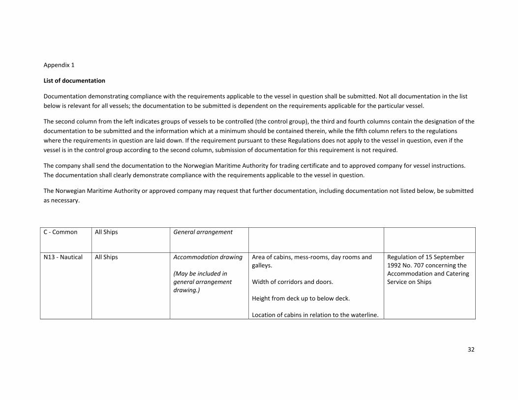
32
Appendix 1
List of documentation
Documentation demonstrating compliance with the requirements applicable to the vessel in question shall be submitted. Not all documentation in the list
below is relevant for all vessels; the documentation to be submitted is dependent on the requirements applicable for the particular vessel.
The second column from the left indicates groups of vessels to be controlled (the control group), the third and fourth columns contain the designation of the
documentation to be submitted and the information which at a minimum should be contained therein, while the fifth column refers to the regulations
where the requirements in question are laid down. If the requirement pursuant to these Regulations does not apply to the vessel in question, even if the
vessel is in the control group according to the second column, submission of documentation for this requirement is not required.
The company shall send the documentation to the Norwegian Maritime Authority for trading certificate and to approved company for vessel instructions.
The documentation shall clearly demonstrate compliance with the requirements applicable to the vessel in question.
The Norwegian Maritime Authority or approved company may request that further documentation, including documentation not listed below, be submitted
as necessary.
C ‐ Common All Ships General arrangement
N13 ‐ Nautical All Ships Accommodation drawing (May be included in general arrangement drawing.)
Area of cabins, mess‐rooms, day rooms and galleys. Width of corridors and doors. Height from deck up to below deck. Location of cabins in relation to the waterline.
Regulation of 15 September 1992 No. 707 concerning the Accommodation and Catering Service on Ships

33
All Ships Escape routes (May be included in fire control and safety plan)
Means of access, exits and means of escape. Stairways and ladders Width of stairways and appurtenant doors.
Regulation of 15 September 1992 No. 707 concerning the Accommodation and Catering Service on Ships
All Ships Navigating bridge visibility (May be included in general arrangement drawing.)
Blind sectors on bridge Details of windows on bridge
Regulation of 15 September 1992 No. 701 concerning Navigational Aids and Arrangements on the Bridge and in the Wheelhouse, and Communication Equipment in the Wheelhouse of Ships
All Ships Lighting arrangement
Placement Blind sectors Type approval certificate
Regulations of 1 December 1975 No. 5 for Preventing Collisions at Sea
All Ships Wheelhouse arrangement
Layout Profile Cross‐section of forward and after sections and sides. Seats in radio room. Location of equipment Information about equipment regarding manufacturer and type approval.
Regulation of 15 September 1992 No. 701 concerning Navigational Aids and Arrangements on the Bridge and in the Wheelhouse, and Communication Equipment in the Wheelhouse of Ships

34
RM9 ‐ Life‐saving appliances
All Ships Life‐saving arrangements (May be included in fire control and safety plan)
Lifeboats and liferafts with davits in relation to hull and propeller. Arrangements for bringing persons gently on board, if any. Liferafts Means of embarkation Radar transponders and EPIRB. Lifejackets Lifebuoys Immersion suits Water outlets in the vessel's side. Manufacturer, size, type, capacity, etc., shall be indicated for the life‐saving equipment.
Regulation of 17 December 2004 No. 1855 concerning life‐saving appliances on cargo ships
All Ships Rescue boat arrangement
Foundation and underlying structure of davit with appurtenant calculations.
Regulation of 17 December 2004 No. 1855 concerning life‐saving appliances on cargo ships
M12 ‐ Machine
All new ships between 8 and 15 metres All ships between 15 and 24 metres
Fuel oil arrangement
Regulations of dd. month 2014 concerning construction and supervision of smaller cargo ships

35
All new ships between 8 and 15 metres All ships between 15 and 24 metres
Bilge water arrangement
Arrangement of bilge water system Calculations of system capacity
Regulations of dd. month 2014 concerning construction and supervision of smaller cargo ships
All new ships between 8 and 15 metres All ships between 15 and 24 metres
Sea water inlets and outlets
Regulations of dd. month 2014 concerning construction and supervision of smaller cargo ships
All new ships between 8 and 15 metres All ships between 15 and 24 metres
Starting air system
Regulations of dd. month 2014 concerning construction and supervision of smaller cargo ships
All new ships between 8 and 15 metres All ships between 15 and 24 metres
Machinery space arrangement
Arrangement of machinery spaces Means of escape from machinery spaces
Regulations of dd. month 2014 concerning construction and supervision of smaller cargo ships
All new ships between 8 and 15 metres All ships between 15 and 24 metres
Ballast water arrangement
Arrangement of ballast water system Calculations of system capacity
Regulations of dd. month 2014 concerning construction and supervision of smaller cargo ships
All new ships between 8 and 15 metres All ships between 15 and 24 metres
Propulsion and propeller arrangement
Regulations of dd. month 2014 concerning construction and supervision of smaller cargo ships

36
All new ships between 8 and 15 metres All ships between 15 and 24 metres
Documentation for machinery
Type approval from recognised classification society for propulsion machinery, auxiliary machinery, steering gear, boilers and pressure vessels.
Regulations of dd. month 2014 concerning construction and supervision of smaller cargo ships
All new ships between 8 and 15 metres All ships between 15 and 24 metres
Report or confirmation concerning a completed torsional oscillation check for machinery with an output of more than 500 kW, or 300 kW if the length of the shaft arrangement exceeds 6 metres.
E16 ‐ Electrical documentation
All new ships Layout of emergency generator room
Arrangement of room where the emergency source of power is located
Regulations of dd. month 2014 concerning construction and supervision of smaller cargo ships
All new ships Power balance for emergency power
Power balance/load analysis for the emergency power system
Regulations of dd. month 2014 concerning construction and supervision of smaller cargo ships
All new ships Emergency lighting
Lighting of muster stations, as well as corridors, stairways and exits giving access to the muster stations
Regulations of dd. month 2014 concerning construction and supervision of smaller cargo ships
S14 ‐ Hull
New ships between 8 and 15 metres All ships between 15 and 24 metres
Profile and deck plan Longitudinal showing water ballast tanks, bulkheads, erections, hatches etc.
Shall, inter alia, include the vessel's main dimensions, baseline, maximum draught and frame spacing.
Regulations of dd. month 2014 concerning construction and supervision of smaller cargo ships

37
New ships between 8 and 15 metres All ships between 15 and 24 metres
Midship section Transverse showing design of bottom, camber etc.
Shall show the frames essential for the dimensioning, generally at least one frame in each space. The midship section drawing shall contain information about the vessel's equipment number and anchor equipment. The baseline shall be sketched in for each frame.
Regulations of dd. month 2014 concerning construction and supervision of smaller cargo ships
New ships between 8 and 15 metres All ships between 15 and 24 metres
Shell expansion Shall show the shell expansion in unfolded condition.
Regulations of dd. month 2014 concerning construction and supervision of smaller cargo ships
New ships between 8 and 15 metres All ships between 15 and 24 metres
Watertight / tank bulkheads
Regulations of dd. month 2014 concerning construction and supervision of smaller cargo ships
New ships between 8 and 15 metres All ships between 15 and 24 metres
Forepart and stern construction drawing
Regulations of dd. month 2014 concerning construction and supervision of smaller cargo ships
New ships between 8 and 15 metres All ships between 15 and 24 metres
Foundations for deck machinery/equipment
The drawings shall show the foundations including the underlying structure of anchor winches, towing winches, davits, etc. The capacity of the various load‐bearing components shall be specified on the drawings.
Regulations of dd. month 2014 concerning construction and supervision of smaller cargo ships

38
New ships between 8 and 15 metres All ships between 15 and 24 metres
Deck arrangement The drawing shall show the placement of deck machinery (winches, davits, etc.), launching arrangement, etc.
Regulations of dd. month 2014 concerning construction and supervision of smaller cargo ships
New ships between 8 and 15 metres All ships between 15 and 24 metres
Hatch cover for cargo spaces
Regulations of dd. month 2014 concerning construction and supervision of smaller cargo ships
New ships between 8 and 15 metres All ships between 15 and 24 metres
Rudder arrangement Regulations of dd. month 2014 concerning construction and supervision of smaller cargo ships
New ships between 8 and 15 metres All ships between 15 and 24 metres
Dimensioning calculations Dimensioning calculations in accordance with chapter 2 of the Regulations of dd. month year concerning construction and supervision
of smaller cargo ships. The calculations shall support the selected dimensions.
Regulations of dd. month 2014 concerning construction and supervision of smaller cargo ships
All Ships Documentation for anchor and mooring equipment
Selected anchor equipment and equipment number pursuant to the Regulations shall be sketched in, normally on the midship section drawing. (Or other relevant drawing, e.g. anchor arrangement.) Calculation of equipment number shall be submitted.
Regulations of dd. month 2014 concerning construction and supervision of smaller cargo ships

39
S10 ‐ Stability All Ships Preliminary stability calculations
Intact stability calculations, with loading conditions Input data for hull description Instructions for use of anti‐rolling tanks,
Regulations of dd. month 2014 concerning construction and supervision of smaller cargo ships
All Ships
Documentation for towing and anchor‐handling equipment (Vessels with a particular class for anchor‐handling and towing equipment may instead submit documentation thereof.)
Drawings and calculations of the towing/anchor‐handling winch, wire/ chain stopper, guide pins, towing hooks, etc. shall be submitted for approval. An arrangement drawing of the anchor‐handling plan showing the system to be used shall be submitted for inspection and possible spot test. The drawing shall show the wire routing and all equipment forming part of the ship’s anchor‐handling system, as well as fastenings on deck which may be used during anchor‐handling. The drawing shall also indicate the SWL/breaking load for all components forming part of the system. An arrangement drawing of the towing arrangement plan for tugs for ocean towing shall be submitted for inspection and possible spot test. An arrangement drawing in accordance with subparagraph a) and/or b) shall be delivered with the ship together with certificates for movable equipment.
Regulations of dd. month 2014 concerning construction and supervision of smaller cargo ships

40
indicating limitations when using anti‐rolling tanks. The instructions shall be supported by loading conditions. GMmin/ KGmaxcurves with examples of the use of these. Cross curves Hydrostatic curves and tables Tank plan Sounding tables for tanks Lines drawing Outline of buoyancy volumes with means of closure and flooding openings. Stability information for towing, if any. Information about maximum permitted weight as a function of extension and direction of crane, if applicable. Stability information for anchor‐handling, if any.
All Ships Inclining test report
The inclining test shall be carried out in accordance with the Norwegian Maritime Authority's procedure, and the report shall
Regulations of dd. month 2014 concerning construction and supervision of smaller cargo

41
contain: Lightship data Draught measurements Description of inclining weights, with weight and centre of gravity Length of pendulums and pendulum readings Description of the movements of the inclining weights Arm for moved weights Heeling moment for each move and plot of heeling moment Calculation of GM for the listed ship Additional weights Hydrostatics for heeling waterline Calculation of lightship data
ships
All Ships Final stability calculations
Stability calculations with updated lightship data according to approved inclining test report
Regulations of dd. month 2014 concerning construction and supervision of smaller cargo ships
LS6 ‐ Load line All Ships Freeboard plan
The vessel's overall length, length (L) and moulded depth
Regulations of dd. month 2014 concerning construction and

42
Extension and height of weathertight enclosed superstructure. Location and type of means of closure for hatches in freeboard deck and superstructure. Exterior doors in weathertight superstructure and deckhouse protecting accesses to below freeboard deck and first superstructure deck. Sidescuttles in ship's sides and superstructure. Windows in erections on freeboard deck and first superstructure deck. The heights of coamings and sills of hatches and doors. Location and area of freeing ports. Location and type of valves for sanitary pipelines, scuppers, etc. and of other overboard ventilators. Outline of means of closure, location and indication of height above deck for air pipes and ventilators. Location of deck line at L/2. Bulwarks and guard rails.
supervision of smaller cargo ships

43
Doors in shipside, bow and outboard side.
B19 ‐ Structural fire protection
All new ships Insulation arrangement or fire divisions
Structural fire protection with subdivision into A and B class divisions. Location of all A and B class divisions in bulkheads and decks. Details of A class divisions, with regard to connections and materials used. Categorisation of rooms.
Regulations of dd. month 2014 concerning construction and supervision of smaller cargo ships
All new ships Door plan
Fire class standard of doors Dimensions of doors Hold‐back mechanisms, if any Ventilation openings or similar in the doors, if any.
Regulations of dd. month 2014 concerning construction and supervision of smaller cargo ships
All new ships Ventilation arrangement
Arrangement/layout of the ventilation ducts in accommodation spaces, control stations, service spaces, store‐rooms, machinery spaces and, if applicable, cargo spaces and pump rooms. Details of penetrations in bulkheads and decks.
Regulations of dd. month 2014 concerning construction and supervision of smaller cargo ships
B11 ‐ Fire‐fighting
All Ships Fire control and safety plan
The drawing shall show the location of: The vessel's structural fire protection with A and B class bulkheads. Fire detection and fire alarm
Regulations of dd. month 2014 concerning construction and supervision of smaller cargo ships Regulation of 17 December

44
Sprinkler systems Fixed fire‐extinguishing equipment Portable fire‐extinguishing equipment Access to spaces and decks etc. Stopping of fans and dampers in the ventilation system. Shut‐off valves for fuel oil and lubricating oil. Life‐saving appliances and other safety equipment Symbols shall be in accordance with a recognised international standard. Fire pump and emergency fire pump, if any, with capacity.
2004 No. 1856 concerning radio communication Regulation of 17 December 2004 No. 1855 concerning life‐saving appliances on cargo ships
All new ships Fire main
Arrangement of fire main system Location of main fire pumps and hydrants Location of emergency fire pump Capacity of main fire pumps and emergency fire pumps
Regulations of dd. month 2014 concerning construction and supervision of smaller cargo ships
All new ships Fire alarm and fire detection
General arrangement showing the location of: ‐ fire detection in accommodation, service and machinery spaces
Regulations of dd. month 2014 concerning construction and supervision of smaller cargo

45
‐ fire alarmsConnection diagram (one‐line diagram) showing: ‐ coupling of the loops for the units indicated on the general arrangement Copy of type approval certificate.
ships
All new ships Fixed fire‐extinguishing system in machinery spaces
Type approval certificate Manual showing documentation required by type approval certificate Arrangement drawings showing location of nozzles and release stations Capacity calculations Instructions for activation of system
Regulations of dd. month 2014 concerning construction and supervision of smaller cargo ships
All new ships Manual for fire‐extinguishing system
Regulations of dd. month 2014 concerning construction and supervision of smaller cargo ships