Refrigeration System Equipment Room Design
8
Refrigeration System Equipment Room Design The purpose of this newsletter is to provide interim guidance to designers of mechanical equipment rooms housing chillers that employ refrigerants classified by ASHRAE Standard 34-1992. The advent of new and replacement non-CFC refrigerants has resulted in a great deal of uncertainty in the design community. ASHRAE has attempted to remedy a large share of this uncertainty by quickly rewriting Standards 15 and 34 to accommodate recently applied HCFC and HFC refrigerants. Interim guidance may be helpful until both of these standards are approved and in full circulation. The Fane Company intends to provide an application manual entitled "Refrigeration System Equipment Room Design," based on the newly approved ASHRAE Standard 75-1992, Safety Code for Mechanical Refrigeration. Publication of that manual will obsolete this newsletter. The focus of this newsletter is on changes to mechanical equipment room design requirements brought on by a change from CFC- 7 1 to the alternative HCFC-123 in centrifugal chillers. Both are low-pressure refrigerants that operate at subatmospheric pressures in evaporators and slightly above atmospheric pressure in condensers of centrifugal water chillers.A smaller number of centrifugal chiller plants employ medium or high-pressure refrigerants. It is important to recognize that the ASHRAE safety code (Standard 15) applies to equipment rooms with chillers using all refrigerants, except water. Thus, changes to this standard are significant to designers of chiller systems, regardless of the refrigerant used in the chillers. ASHRAE Standards The American Society of Heating, Refrigerating and Air Conditioning Engineers (ASHRAE) is an organization whose members come from all aspects of the HVAC industry. Together, the members draft "standards" and "guidelines" to assure safe distribution and use of HVAC products. These standards can be considered state- of-the-art design practices; frequently they are adopted and enforced by local code authorities. Until this occurs, it is the owner's/designer'sprerogative to specify design according to the standards. However, when design issues are raised in court, the legal system often refers to the state-of-the-artdesign practice at the time the building was designed. The Design Process A system designer who faces the task of designing a mechanical equipment room that houses refrigeration equipment needs a "recipe." Based on our review of Standards 15 and 34, a nine-step process seems well suited. 1 Define safety group classification. 2 Define occupancy group classification. 3 Define refrigerating system classification. 4 Determine which refrigerant quantity rules 5 Determine best equipment layout arrangement. 6 Design ventilation system. 7 Design refrigerant pressure-relief piping. 8 Select safety monitoring equipment. 9 Determine extent of automation desired. -
Transcript of Refrigeration System Equipment Room Design

Refrigeration System Equipment Room Design The purpose of this newsletter is to provide interim guidance to designers of mechanical equipment rooms housing chillers that employ refrigerants classified by ASHRAE Standard 34-1992. The advent of new and replacement non-CFC refrigerants has resulted in a great deal of uncertainty in the design community. ASHRAE has attempted to remedy a large share of this uncertainty by quickly rewriting Standards 15 and 34 to accommodate recently applied HCFC and HFC refrigerants. Interim guidance may be helpful until both of these standards are approved and in full circulation.
The Fane Company intends to provide an application manual entitled "Refrigeration System Equipment Room Design," based on the newly approved ASHRAE Standard 75-1992, Safety Code for Mechanical Refrigeration. Publication of that manual will obsolete this newsletter.
The focus of this newsletter is on changes to mechanical equipment room design requirements brought on by a change from CFC- 7 1 to the alternative HCFC-123 in centrifugal chillers. Both are low-pressure refrigerants that operate at subatmospheric pressures in evaporators and slightly above atmospheric pressure in condensers of centrifugal water chillers. A smaller number of centrifugal chiller plants employ medium or high-pressure refrigerants. It is important to recognize that the ASHRAE safety code (Standard 15) applies to equipment rooms with chillers using all refrigerants, except water. Thus, changes to this standard are significant to designers of chiller systems, regardless of the refrigerant used in the chillers.
ASHRAE Standards The American Society of Heating, Refrigerating and Air Conditioning Engineers (ASHRAE) is an organization whose members come from all aspects of the HVAC industry. Together, the members draft "standards" and "guidelines" to assure safe distribution and use of HVAC products. These standards can be considered state- of-the-art design practices; frequently they are adopted and enforced by local code authorities. Until this occurs, it is the owner's/designer's prerogative to specify design according to the standards. However, when design issues are raised in court, the legal system often refers to the state-of-the-art design practice at the time the building was designed.
The Design Process A system designer who faces the task of designing a mechanical equipment room that houses refrigeration equipment needs a "recipe." Based on our review of Standards 15 and 34, a nine-step process seems well suited.
1 Define safety group classification. 2 Define occupancy group classification. 3 Define refrigerating system classification. 4 Determine which refrigerant quantity rules 5 Determine best equipment layout arrangement. 6 Design ventilation system. 7 Design refrigerant pressure-relief piping. 8 Select safety monitoring equipment. 9 Determine extent of automation desired.
-

Safety Group Two ASHRAE Standards deal with the use and handling of refrigerant in an equipment room: Standard 15 and Standard 34. Purpose and scope of each is shown in Figure 1. Standard 34 defines "Safety Group Classifications of Refrigerants" according to their toxicity and flammability. The measure of toxicity delineation between Group A and Group B refrigerants is a "threshold limit value-time weighted average: (TLV-TWA) concentration of 400 parts per million (ppm), as shown in Figure 2. Standard 34 defines TLV-TWA as ". . .the time weighted average concentration for a normal 8-hour workday and a 40-hour work week, to which nearly all workers may be repeatedly exposed, day after day, without adverse effect"
The primary application of this definition is likely to be workers in facilities that produce or store the chemical; although a case could be made for those rare mechanical equipment rooms where workers are present on a continuous 40-hour week basis.
The letter designation for toxicity is followed by a number used to designate flammability. Refrigerants with no flame propagation potential are given a "1 ,I' lower flammability refrigerants receive a "2" and refrigerants with a higher flammability are assigned a "3." Standard 34 defines the flame propagation and lower flammability limits (LFL) for each of these three categories.
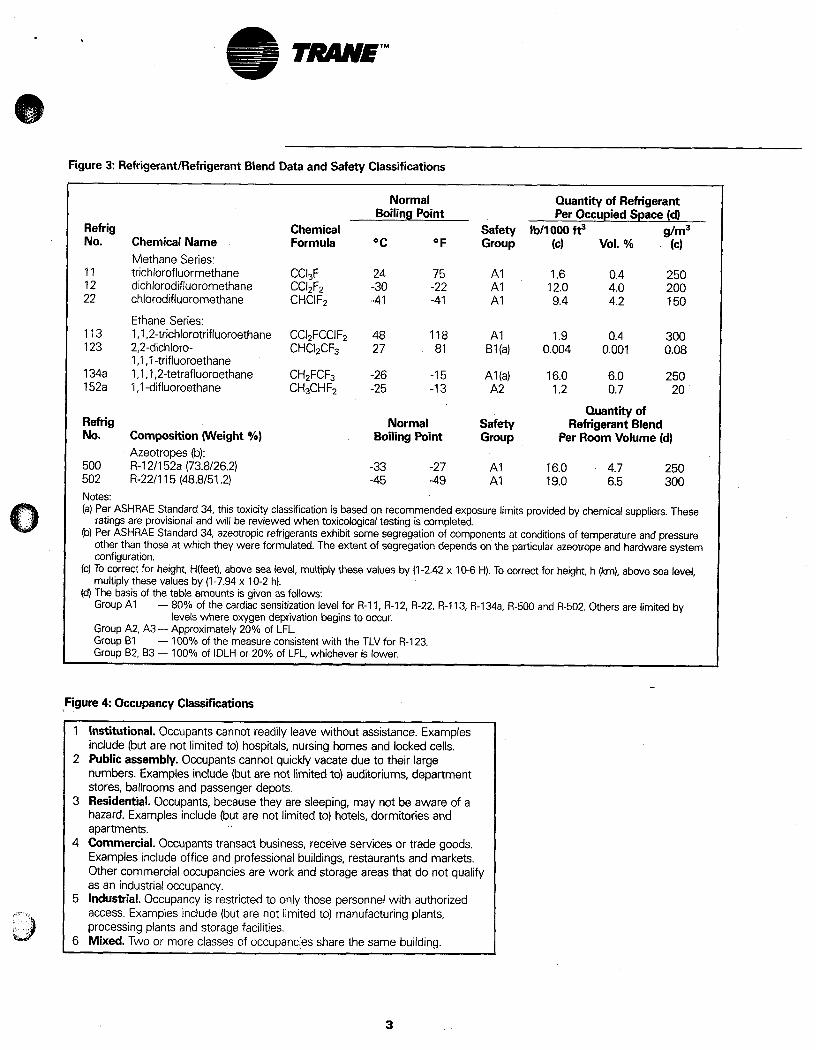
Specific values are shown in Figure 2. Designators for the most common refrigerants are shown in Figure 3. ASHRAE Standard 15 uses these same designators to delineate the design criteria for refrigeration equipment located in or near a building.
Occupancy Group Occupancy classifications are based on the ability of people to respond in the event of an emergency. ASHRAE has defined six occupancy classifications that reflect how a building is used. All equipment, other than piping, located less than 20 feet from any building opening is governed by one of these six occupancy classifications, shown in Figure 4.
Figure 1
Standard 34: Standard 15: Number Designation and Safety Classification of Refrigerants
Purpose: ". . .to establish a simple means of referring to common refrigerants instead of using the chemical name, formula or trade name. It also establishes a uniform system for assigning reference numbers and safety classifications to refrigerants."
Scope: " . . .provides an unambiguous system for numbering refrigerants and assigning composition-designating prefixes for refrigerants. Safety classifications based on toxicity and flammability data are included.
Safety Code for Mechanical Refrigeration
Purpose: " . . .to promote the safe design, construction, installation and operation of refrigerating systems."
Scope: ". . . establishes reasonable safeguards of life, limb, health and property; defines practices that are consistent with safety; and prescribes safety standards."
". . . applies a) to mechanical refrigerating systems and heat pumps used in the occupancies defined in Section 4 (occupancy classification) and installed subsequent to adoption of this code and b) to parts replaced and components added after adoption of this code."
Figure 2: ASHFiAE Standard 34 Refrigerant Safety Classifications
Safety Group Higher (a) Group A3 Group B3 Flammability
Lower (b) Group A2 Group 82 Flammability No Flame Group A I Group B1 Propagation
Lower Higher Toxicity(c) Toxicity(c)
Notes: Class A signifies refrigerants for which toxicity has not been identified at concentrations less than or equal to 400 ppm, based on data used to determine threshold limit value-time weighted average (TLV-TWA) or consistent indices.
Class B signifies refrigerants for which there is evidence of toxicity at concentrations below 400 ppm, based on data used to determine TLV-TWA or consistent indices.
Class 1 indicates refrigerants that do not show flame propagation when tested in air at 101 kPa (14.7 psia) and 18 C (65 F).
Class 2 signifies refrigerants having a lower flammability limit (LFL) of more than 0.10 kg/m3 (0.00625 Ib/ft3 at 21 C and 101 kPa (70 F and 14.7 psia) and a heat combustion of less than 19,000 kJ/kg (8,174 Btu/lb). The heat of combustion shall be calculated assuming that combustion products are in the gas phase and in their most stable state (e.g., C, N, S give C02, N,, SO3, F and CI give HF and HCI if there is enough H in the molecule, otherwise they give F2 and CI,; excess H is converted to H20.
Class 3 indicates refrigerants that are highly flammable, as defined by an LFL of less than or equal to 0.10 kg/m3 (0.00625 Ib/ft3 at 21 C and 101 kPa (70 F and 14.7 psia) or a heat of combustion greater than or equal to 19,000 kJ/kg (8,174 Btu/lb). The heat of combustion is calculated as explained above in the definition of a Class 2 category.
2
~ ~~
Figure 3: Refrigerant/Refrigerant Blend Data and Safety Classifications
1 Institutional. Occupants cannot readily leave without assistance. Examples ' include (but are not limited to) hospitals, nursing homes and locked cells. 1 2 Public assembly. Occupants cannot quickly vacate due to their large
numbers. Examples include (but are not limited to) auditoriums, department 1 stores, ballrooms and passenger depots. 1 3 Residential. Occupants, because they are sleeping, may not be aware of a
hazard. Examples include (but are not limited to) hotels, dormitories and apartments.
4 Commercial. Occupants transact business, receive services or trade goods. Examples include office and professional buildings, restaurants and markets. Other commercial occupancies are work and storage areas that do not qualify as an industrial occupancy.
5 Industrial. Occupancy is restricted to only those personnel with authorized access. Examples include (but are not limited to) manufacturing plants, processing plants and storage facilities.
6 Mixed. Two or more classes of occupancies share the same building.
Refrig No.
11 12 22
113 123
134a 152a
Chemical Name Methane Series: trichlorofluormethane dichlorodifluoromethane chlorodifluoromethane
Ethane Series: 1 ,I .2-trichlorotrifluoroethane 2,2-dichloro- 1 ,I ,I-trifluoroethane 1 ,I ,1,2-tetrafluoroethane 1 ,I -difluoroethane
Normal Boiling Point
Chemical Formula OC OF
CC13F 24 75 CC12FZ -30 -22 CHCIF2 -41 -41
CC12FCCIF2 48 118 CHC12CF3 27 81
CH2FCF3 -26 -1 5 CH3CHFz -25 -1 3
Quantity of Refrigerant Per Occupied Space (d)
Ib/l 000 f? g/m3 (C) VOl. % (C)
1.6 0.4 250 12.0 4.0 200 9.4 4.2 150
1.9 0.4 300 0.004 0.001 0.08
16.0 6.0 250 1.2 0.7 20
Quantity of Refrig Normal Safety Refrigerant Blend No. Composition (Weight YO) Boiling Point Group Per Room Volume (d)
500 R-I 2/152a (73.8/26.2) -33 -27 A I 16.0 4.7 250 502 R-22/115 (48.8/51.2) -45 -49 A I 19.0 6.5 300 Notes: (a) Per ASHRAE Standard 34, this toxicity classification is based on recommended exposure limits provided by chemical suppliers. These
ratings are provisional and will be reviewed when toxicological testing is completed. (b) Per ASHRAE Standard 34, azeotropic refrigerants exhibit some segregation of components at conditions of temperature and pressure
other than those at which they were formulated. The extent of segregation depends on the particular azeotrope and hardware system configuration.
(c) To correct for height, H(feet), above sea level, multiply these values by (1 -2.42 x 10⁻⁶ H). To correct for height, h (km), above sea level, multiply these values by (1-7.94 x 10⁻² h).
(d) The basis of the table amounts is given as follows: Group AI
Group A2. A3 - Approximately 20% of LFL. Group B1 Group 82, B3 - 100% of IDLH or 20% of LFL, whichever is lower.
Azeotropes (b):
- 80% of the cardiac sensitization level for R-I 1, R-I 2, R-22, R-I 13, R-I 34a, R-500 and R-502. Others are limited by
- 100% of the measure consistent with the TLV for R-I 23.
levels where oxygen deprivation begins to occur.
3

Figure 6 System Application Requirements
Refrig Group
A I
A2
A3
B1
82
B3
System Probability
High Low High Low High Low High Low High Low High Low
Institutional 1 4 5 7 9 9
1 6 4 56 7: 9 9
Occupancy Classification Public Assembly,
Residential, Commercial 2 4 5 7 9 9 2,6 4 5,6 7 9 9
Industrial 3 4
36.8 7
3,6,8 7 3.6 4
368 7
3,6,8 7
Refrigerant Quantity Rules From ASH RAE Standard 15 1 The refrigerant amount is limited to 50% of that listed in Figure 3, except Rule 2 applies in
kitchens, laboratories and mortuaries. If any portion of a refrigerant system containing more than one pound of refrigerant (except R-744) is in a room with a flame-sustaining device, this device shall be provided with a hood to exhaust combustion products to the open air. Otherwise, Rules 5 and 6 shall be followed.
2 The refrigerant amount is limited as listed in Figure 3. 3 The refrigerant amount is unlimited when:
a) the machinery-containing area is separated from the areas of the building not containing machinery by tight construction with tight-fitting doors;
b) free escape from the area is unhampered; c) the number of persons in a machinery-room-containing-space on any floor above the
first floor (ground level or deck level) is equal to or less than one person per 100 sq ft (9.3m2) of floor area, or if the number exceeds one person per 100 sq ft (9.3m2), the machinery-containing space shall be provided with the required number of doors opening directly into approved building exits;
concentrate to provide an alarm at the following levels: Group A1 below 19.5% volume oxygen; Groups A2 and A3 at levels listed in Figure 3; and Groups BI, 82 and 83 (except ammonia) at no higher than their TLV (or toxicity measure consistent therewith). Otherwise the rules for commercial occupancy apply.
4 When the quantity of refrigerant in the largest system exceeds Figure 3 amounts, all
5 Refrigerant amounts and types of systems are limited as shown in Figure 6. 6 Applications involving air conditioning for human comfort are not allowed. 7 When the quantity of refrigerant in the largest system exceeds Figure 3 amounts, all
d) detectors are located in areas where refrigerant vapor from a leak is likely to
refrigerant-containing parts, except piping and those parts outside the building, shall be installed in a machinery room per Section 11.13 of ASHRAE Standard 15-1992.
refrigerant-containing parts, except piping and those parts outside the building, shall be installed in a machinery room per Section 11 .I4 of ASHRAE Standard 15-1 992 with limitations on refrigerant quantities as follows: 550 Ib (250kg)- Institutional No limit except Rule 8- Public Assembly No limit except Rule 8- Residential No limit except Rule 8- Commercial No limit except Rule 8- Industrial Otherwise, Rule 5 applies to the amount of Group A2, A3, B2 or 83 refrigerant in the system.
8 When the quantity of refrigerant exceeds Figure 3 amounts, all refrigerant-containing parts except piping, low-side components, condensers and parts outside the building shall be installed in a machinery room per Section 1 1 .I 3 of ASHRAE Standard 15-1 992. In addition, refrigerants of Groups A2, A3, B2 and B3 shall meet the following requirements: a) The special machinery room requirements of Section 1 1 .I 4 of ASHRAE Standard 15-1 992
shall apply. b) Except for ammonia, amounts in excess of 1100 Ib (500 kg) shall be approved by the
authority having jurisdiction. 9 Use of these refrigerants is prohibited except in laboratories in commercial occupancies. Only
unit systems containing not more than 6.6 Ib (3kg) of Group A3 or B3 refrigerant shall be used unless the laboratory is occupied.
Controls must be provided to increase the ventilation rate from normal to purge. Automatic control shall be accomplished by linking the alarm output of a refrigerant (or oxygen deprivation) monitor into the ventilation system. Additionally, a switch to initiate the purge ventilation rate should be located outside the main entrance to the mechanical equipment room
The location of the ventilation system inlets and discharges are referenced by Standard 15 only with regard to their guarding, avoidance of recirculation and their exclusive dedication to ventilation of the equipment room. Figure 8 suggests a configuration that provides for the complete purging of refrigerant from the equipment room by "sweeping" air across all refrigeration equipment.
When exhaust fans are used to keep the equipment room cool, or remove smoke from combustion, inlets are often located near the ceiling as both heat and smoke tend to rise. If the same ventilation system serves as the refrigerant exhauster, provisions must be made for inlets at both floor and ceiling levels, because refrigerants are three to five times heavier than air. Figure 9 shows a proper way to handle this dual-purpose requirement.
Refrigerant Pressure Relief Piping In general, all equipment specifications require pressure relief devices to protect components and packages from rupture due to high pressure fIom fire or other abnormal conditions. This requirement is also spelled out in Standard 15. Once the equipment is installed, each pressure relief device or fusible plug must be piped to a safe location outside the equipment room. The terminus of this piping needs to be at least 15 feet above the adjoining ground and at least 20 feet from any window, ventilation opening or exit in any building. PVC piping is not recommended since many adhesives used in this type piping construction have not been tested for refrigerant compatibility.
5

Refrigerating System Refrigerating system classification is the third step. There are five designations, but they are based on the method used to extract or deliver heat. Figure 5 identifies these five system types schematically and by name. Systems are either high probability or low probability systems. System probability indicates the relative likelihood of refrigerant leaking from a refrigerant system into an occupancy- classified area. Direct and indirect open spray systems are high probability systems. The basic design or location of components is such that refrigerant leakage from a failed connection, seal or component could enter the area under consideration. Examples of these systems are direct-expansion split systems, rooftop air conditioners and open spray air washers. All other systems, including most chillers, are considered low probability.
Refrigerant Quantity Figure 6 indicates that the application of group A1 and B1 refrigerants in low probability systems in any occupancy results in Rule 4. Rule 4 states that if the refrigerant quantities exceed those shown in Figure 3, as almost always occurs, a mechanical equipment room is required.
Equipment Layout Once the refrigerant quantities shown in Figure 3 are exceeded and Rule 4 applies, it points to Section 1 1.1 3 of ASHRAE Standard 15. Virtually any enclosed plant employing any chiller using any of the common commercial refrigerants (R-1 1, R-12, R-22, R-500, R-123 or R-l34a) should be designed in accordance with Section 1 1.1 3 which prescribes specific requirements for:
8
Minimum headroom
Tight-fitting doors
Oxygen or refrigerant sensor/detector (with periodic testing)
Mechanical ventilation
Prohibited open flames
Restricted personnel.
8
8
8
8
8
Figure 5: Refrigeration System Classification (from ASHRAE Standard 34)
Air Or Substance System Cooling Or To Be Cooled Or
Designation
Direct
Indirect Open Spray
Vent i!
Indirect Closed
While the exact equipment layout is not specified, it is generally good practice to situate chillers such that airflow patterns around them do not result in areas of air stagnation. Figure 7 shows two possible configurations for a multiple chiller plant. Positioning chillers as shown in Arrangement A provides good air movement, .while Arrangement B creates stagnant air areas between the chillers.
Ventilation Ventilation volume requirements for mechanical equipment rooms are covered by Standard 15. Most rooms require mechanical ventilation because they are fully enclosed and usually attached in some way to the remainder of the building. Standard 15 defines two distinct ventilation rates: one for normal ventilation and another for purging. The normal ventilation rate applies only to occupied periods and is the larger of: a) 0.5 cfm per square foot of equipment room area or 20 cfm per person
4
or b) the air volume required to maintain a maximum temperature rise of 18 F.
The purge ventilation rate is found by the equation Q = 100 x 0 = airflow (cu ft/min) G = mass of refrigerant (Ibs) in the largest
where
system, any part of which is located in the machinery room.
"Q' represents the minimum airflow that the ventilation system must be capable of providing while the equipment room is purged of refrigerants. According to Standard 15, it is, not necessary to run the ventilation system at this volume continuously, provided that the normal rate
Thus two distinct ventilation rates are defined for the mechanical equipment room. Multiple fans, multispeed fans or other modulation devices may be used if a two-tiered ventilation system is used.
is maintained during occupancy. I /
(... ...I tjl ,,
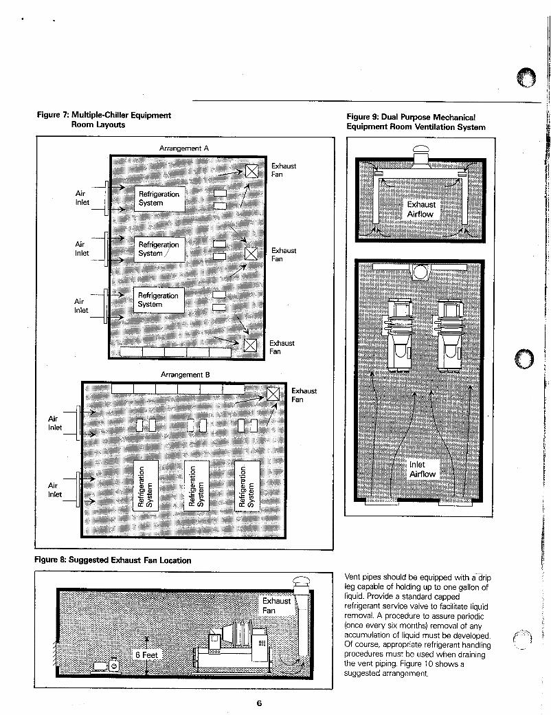
Figure 7 Multiple-Chiller Equipment Room Layouts
Figure 9: Dual Purpose Mechanical Equipment Room Ventilation System
Air Inlet
Air Inlet
Arrangement A
- Air Inlet -
Arrangement B
Exhaust Fan
Exhaust Fan
Exhaust Fan
Exhaust Fan
Figure 8: Suggested Exhaust Fan Location
I 1 Vent pipes should be equipped with a3rip leg capable of holding up to one gallon of liquid. Provide a standard capped refrigerant service valve to facilitate liquid removal. A procedure to assure periodic (once every six months) removal of any accumulation of liquid must be developed. Of course, appropriate refrigerant handling procedures must be used when draining the vent piping. Figure 10 shows a suggested arrangement.
I
6

Figure 1 0 Suggested Refrigerant Vent Piping
1 -2
1. Roof. 2. Alternate piping arrangment. 3. Purge discharge vent line. 4. Outside wall. 5. Rupture disc assembly. 6. Flexible steel connection. 7. Drip leg (length as required for
8. %" FL x lh'' NPT drain valve. easy access).
Purge units are used on low pressure chillers to remove water and noncondensable gas that have found their way into the refrigerant circuits. In the course of separating and eliminating noncondensable gas from the refrigerant, a certain amount of refrigerant is carried along with the purge unit discharge. This refrigerant must be piped to a place outside the equipment room, according to Standard 15. It is convenient to use the same vent piping required for the pressure relief, as shown in Figure IO. Additionally, it is prudent to follow these three simple rules for equipment Selection
1 Choose a purge unit with low refrigerant- to-noncondensable-gas discharge ratio and one that can operate with the chiller off. 2 Routinely monitor the chiller for leaks by logging the operation of the purge system and the chiller operating hours. This data provides an excellent indicator of refrigeration system integrity. 3 Choose a purge unit that embodies a safety system to prevent excessive purging due to malfunction or a large leak.
Safety Monitoring Equipment According to Standard 15, all equipment rooms containing refrigerants must be equipped with a long-term monitor that will automatically signal an alarm and start the ventilation system. Long-term monitors have the following characteristics: 4 Permanently mounted. 5 Continuously operated. 6 Stable over the range of temperatures, humidities and barometric pressures to which they will be exposed. 7 Zero drift or auto-zeroing. 8 Outputs to trigger external alarm(s) and to start auxiliary equipment. 9 Long service life. 10 Require little maintenance. 11 Refrigerant-specific (to avoid nuisance alarms).
Monitors for group AI refrigerants must use an oxygen deprivation sensor. All other refrigerants must use a refrigerant sensor. With an oxygen deprivation sensor, a monitor is set to alarm at 19.5 percent volume, since there is insufficient odor warning, and the greatest danger is asphyxiation. A refrigerant sensor type is set no higher than the refrigerants TLV':
Refrigerant sensors can also be used with Group 1 refrigerants, providing much faster detection of refrigerant leaks and thus minimizing loss of refrigerant. This attribute can be valuable in connection with high pressure refrigerants, where refrigerant
losses can be large and can occur quickly, compared to low pressure refrigerants.
Sensor location is imprecisely defined by ASHRAE Standard 15 as " . . . locate the sensor where refrigerant is likely to concentrate." Key points to remember are:
Focus on areas of concentration, rather than leakage.
Account for airflow patterns in the equipment room.
Focus on occupant safety as the main objective.
Recognize that occupants are likely exposed to refrigerant danger through inhalation.
0
e
0
0
Taking these factors into account, the recommended height for the sensor is 18 inches above the floor. Occasionally, equipment rooms are oddly shaped and a single sensor may not fulfill all requirements. Single monitors with multipoint sensors are available for these applications. As a general guideline, a refrigeration system should not be more than 50 feet from a refrigerant sensor.
Automation This subject deserves more attention than can be given in this newsletter. Suffice it to say that chiller plant automation systems provide enabling technology to bring cost- effective refrigerant monitoring to any plant. Professional facilities managers recognize the operating benefits associated with automated monitoring, integrated' with the chiller plant automation system. Refrigerant cost savings alone can quickly pay for the added equipment. Further, a permanent refrigerant monitor record can hold valuable data if the proper operation of a plant is ever challenged.
' 1990-1991 Threshold Limit Values for Chemical Substances and Physical Agents and Biological Exposure Indices, American Conference of Governmental Industrial Hygienists, Columbus, OH, 1990. Trane Integrated Comfort"" systems.
7

e h
A Publication of The Trane Company Commercial Systems Group La Crosse, WI 54601
The Systems Manual The Trane Systems Manual is a unique, comprehensive resource that will give you an added advantage whey facing your clients. With the Systems Manual, you can easily pull together a professional HVAC presentation to effectively communicate your system and equipment ideas. This colorful manual consists of marketing presentation brochures that discuss the importance of comfort for six market segments: offices, schools, healthcare, stores, manufacturing and the lodging industry.
Behind each market segment tab are single sheets that describe most of the commonly used airside systems; single-zone, variable air volume, fan-coilhnit ventilators and water-source heat pumps.
Next, on single sheets, are descriptions of popular system options and control strategies such as heat recovery, thermal storage, low temperature air, demand limiting and optimum startlstop, to name a few.
To help communicate the myriad of equipment alternatives, the manual also includes a complete portfolio of Trane equipment in a featurelbenefit format. At this point, system schematic sheets assist in pulling each of the components together as a system.
For existing building projects, a section is devoted to the unique requirements of constant volume systems such as multizone, induction, dual duct and terminal reheat. This section provides an easy to understand description of the system along with energy saving retrofit ideas.
Finally, the manual provides the presentation support for marketing the system designer's efforts in determining which system is best for an application. This section, called computer-aided systems engineering, outlines the system design and analysis tools available from The Trane Company. Overall, a comprehensive systems presentation tool developed for use by HVAC practitioners.
,
For information on how to obtain the Trane Systems Manual, or for information on Trane's broad line of products and services, contact your local Trane commercial sales office.
@American Standard IN. 1992 a Printed on recycled paper as part of 48 The Trane Company's recycling program