
Refining Processes Handbook 2006
222
Technology Solutions Sponsored by:
-
Upload
neagu-mihaela -
Category
Documents
-
view
389 -
download
30
Transcript of Refining Processes Handbook 2006

7/18/2019 Refining Processes Handbook 2006
http://slidepdf.com/reader/full/refining-processes-handbook-2006 1/222
Technology Solutions
Sponsored by:

7/18/2019 Refining Processes Handbook 2006
http://slidepdf.com/reader/full/refining-processes-handbook-2006 2/222
AlkylationAlkylation, catalytic
Alkylation--feed preparation
Alkylation-HF
Alkylation-sulfuric acid
Aromatics
Aromatics extractive distillation
Aromatics recovery
Benzene reduction
Biodiesel
Catalytic dewaxing
Catalytic reforming
Coking
Coking, fluid
Coking,flexi
Crude distillationCrude topping units
Deasphalting
Deep catalytic cracking
Deep thermal conversion
DesulfurizationDewaxing
Dewaxing/wax deoiling
Diesel-ultra-low-sulfur diesel (ULSD)
Diesel-upgrading
Ethers
Ethers-ETBE
Ethers-MTBE
Flue gas denitrification
Flue gas desulfurization-SNOX
Fluid catalytic cracking
Fluid catalytic cracking-pretreatment
Gas treating-H2S removal
Gasification
Gasoline desulfurization
Gasoline desulfurization, ultra deepH2S and SWS gas conversion
H2S removal
Hydroconversion-VGO & DAO
Hydrocracking
Hydrocracking (ISOCRACKING)Hydrocracking (LC-FINING)
Hydrocracking-residue
Hydrodearmatization
Hydrofinishing
Hydrofinishing/hydrotreating
Hydrogen
Hydrogenation
Hydrogen-HTCT and HTCR twin plants
Hydrogen-HTER-p
Hydrogen-methanol-to-shift
Hydrogen-recovery
Hydrogen-steam reforming
Hydrogen-steam-methane
reforming (SMR)
Hydroprocessing, residueHydroprocessing, ULSD
Hydrotreating
Hydrotreating (ISOTREATING)
Hydrotreating diesel
Processes index - 1 [next page]
Technology Solutions
Sponsored by:

7/18/2019 Refining Processes Handbook 2006
http://slidepdf.com/reader/full/refining-processes-handbook-2006 3/222
Hydrotreating/desulfurizationHydrotreating-aromatic saturation
Hydrotreating-lube and wax
Hydrotreating-RDS/VRDS/UFR/OCR
Hydrotreating-resid
Hydrotreating-residue
Isomerization
Isooctene/isooctane
Lube and wax processing
Lube extraction
Lube hydrotreating
Lube oil refining, spent
Lube treating
Mercaptan removal
NOx abatement
NOx reduction, low-temperatureO2 enrichment for Claus units
O2 enrichment for FCC units
Olefin etherfication
Olefins recovery
Olefins-butenes extractive distillationOlefins-dehydrogenation of
light parraffins to olefins
Oligomerization-C3 /C4 cuts
Oligomerization-polynaphtha
Paraxylene
Prereforming with feed ultra purification
Pressure swing adsorption-rapid cycle
Refinery offgas-purification and olefins recovery
Resid catalytic cracking
Slack wax deoiling
SO2 removal, regenerative
Sour gas treatment
Spent acid regneration
Spent lube oil re-refining
Sulfur processing
Sulfur recovery
Thermal gasoil
Treating jet fuel/kerosine
Treating-gasesTreating-gasoline and LPG
Treating-gasoline desulfurization,
ultra deep
Treating-gasoline sweetening
Treating-kerosine and heavy naphtha
sweetening
Treating-phenolic caustic
Treating-pressure swing adsorptionTreating-propane
Treating-reformer products
Treating-spent caustic deep neutralization
Vacuum distillation
Visbreaking
Wax hydrotreating
Wet gas scrubbing
Wet Scrubbing system, EDV
White oil and wax hydrotreating
Processes index - 2 [previous page]
Technology Solutions
Sponsored by:

7/18/2019 Refining Processes Handbook 2006
http://slidepdf.com/reader/full/refining-processes-handbook-2006 4/222
ABB Lummus GlobalAir Products and Chemicals, Inc.
Axens
Bechtel
Belco Technologies Corp.
CB&I
CDTECHChevron Lummus Global LLC.
ConocoPhillips
Davy Process Technology
DuPont
ExxonMobil Engineering & Research
Foster WheelerGas Technology Products
Genoil Inc.
Goar, Allison & Associates
GTC Technology Inc.Haldor Topsoe
Kobe Steel Ltd.
Linde AG
Lurgi
Merichem Chemicals & Refinery Services LLC
Process Dynamics, Inc.Refining Hydrocarbon Technology LLC
Shaw Stone &Webster
Shell Global Solutions International BV
Technip
Uhde GmbH
UOP LLC
Company index
Technology Solutions
Sponsored by:

7/18/2019 Refining Processes Handbook 2006
http://slidepdf.com/reader/full/refining-processes-handbook-2006 5/222
AlkylationCoking
Fluid catalytic cracking
Hydrotreating
Hydrotreating-aromatic saturation
ABB Lummus Global

7/18/2019 Refining Processes Handbook 2006
http://slidepdf.com/reader/full/refining-processes-handbook-2006 6/222
Hydrogen-recoveryOlefins recovery
Air Products and Chemicals, Inc.

7/18/2019 Refining Processes Handbook 2006
http://slidepdf.com/reader/full/refining-processes-handbook-2006 7/222
Alkylation-feed preparationBenzene reduction
Catalytic reforming
Ethers
Gasoline desulfurization, ultra deep
Hydroconversion-VGO & DAO
HydrocrackingHydrocracking-residue
Hydrotreating diesel
Hydrotreating-resid
Isomerization
Lube oil refining, spent
Oligomerization-C3 /C4 cutsOligomerization-polynaphtha
Spent lube oil re-refining
Axens

7/18/2019 Refining Processes Handbook 2006
http://slidepdf.com/reader/full/refining-processes-handbook-2006 8/222
DewaxingDewaxing/wax deoiling
Lube extraction
Lube extraction
Lube hydrotreating
Lube hydrotreating
Wax hydrotreating
Bechtel

7/18/2019 Refining Processes Handbook 2006
http://slidepdf.com/reader/full/refining-processes-handbook-2006 9/222
NOx reduction, low-temperatureSO2 removal, regenerative
Wet Scrubbing system, EDV
Belco Technologies Corp.

7/18/2019 Refining Processes Handbook 2006
http://slidepdf.com/reader/full/refining-processes-handbook-2006 10/222
Catalytic reformingCrude topping units
Hydrogen-steam reforming
Hydrotreating
CB&I

7/18/2019 Refining Processes Handbook 2006
http://slidepdf.com/reader/full/refining-processes-handbook-2006 11/222
Alkylation, catalyticHydrogenation
Hydrotreating
Isomerization
CDTECH

7/18/2019 Refining Processes Handbook 2006
http://slidepdf.com/reader/full/refining-processes-handbook-2006 12/222
DewaxingHydrocracking (ISOCRACKING)
Hydrocracking (LC-FINING)
Hydrofinishing
Hydrotreating (ISOTREATING)
Hydrotreating-RDS/VRDS/UFR/OCR
Chevron Lummus Global LLC.

7/18/2019 Refining Processes Handbook 2006
http://slidepdf.com/reader/full/refining-processes-handbook-2006 13/222
AlkylationCoking
Gasoline desulfurization
Isomerization
Processes:
Technology Solutions, a division of ConocoPhillips, is a premier provider of technology solutions forthe vehicles of today and the oilfields and energy systems of tomorrow. Backed by modern research facilitiesand a strong tradition of innovation, we develop, commercialize and license technologies that help oil andgas producers, refiners and manufacturers reach their business and operational. From enhanced productionmethods, to gasoline sulfur removal processes to valuable catalysts that enhance fuel cell operation, Tech-nology Solutions prepares producers, refiners and consumers alike for a cleaner, more beneficial future.Strengths of Our Business
• Focused efforts on developing and commercializing technologies that enable refiners to economically
produce clean fuels and upgrade hydrocarbons into higher value products• Strategic alignment with both Upstream and Downstream energy segments to effectively capitalize on
extensive R&D, commercial and operational expertise• Strong relationship-building and problem-solving abilities• Customer inter-facing and advocacyIndustries ServedTechnology Solutions supports both Upstream and Downstream energy segments, including:• Carbon and petroleum coke• Gasification• Sulfur chemistry• Hydrocarbon processing and upgrading• Upstream technologies• Enhanced recovery
Corporate OverviewConocoPhillips (NYSE:COP) is an international, integrated energy company. It is the third-largest integrat-
ed energy company in the United States, based on market capitalization, and oil and gas proved reservesand production; and the second largest refiner in the United States. Worldwide, of non government-con-trolled companies, ConocoPhillips has the fifth-largest total of proved reserves and is the fourth-largestrefiner. Headquartered in Houston, Texas, ConocoPhillips operates in more than 40 countries. As of March31, 2006, the company had approximately 38,000 employees worldwide and assets of $160 billion.
For More Information: ConocoPhillips Technology SolutionsEmail: [email protected]
Web: www.COPtechnologysolutions.com
Technology Solutions

7/18/2019 Refining Processes Handbook 2006
http://slidepdf.com/reader/full/refining-processes-handbook-2006 14/222
Prereforming with feed ultra purification
Davy Process Technology

7/18/2019 Refining Processes Handbook 2006
http://slidepdf.com/reader/full/refining-processes-handbook-2006 15/222
Alkylation
DuPont

7/18/2019 Refining Processes Handbook 2006
http://slidepdf.com/reader/full/refining-processes-handbook-2006 16/222
Alkylation-sulfuric acidCatalytic dewaxing
Coking, fluid
Coking,flexi
Fluid catalytic cracking
Gas treating-H2S removal
Gasoline desulfurization, ultra deepGasoline desulfurization, ultra deep
Hydrocracking
Hydroprocessing, ULSD
Lube treating
NOx abatement
Pressure swing adsorption-rapid cycle
Wet gas scrubbing
ExxonMobil Engineering & Research
7/18/2019 Refining Processes Handbook 2006
http://slidepdf.com/reader/full/refining-processes-handbook-2006 17/222
CokingCrude distillation
Deasphalting
Hydrogen-steam reforming
Visbreaking
• Integrated hydrogen solutions: Combining hydrogen recoveryand optimized steam
• Upgrade refinery residuals into value-added products
• Optimize turnaround projects
• Drivers for additional delayed coking capacity in the refiningindustry
• When solvent deasphalting isthe most appropriate technology for upgrading residue
Processes:
Foster Wheeler is a global engineering and construction contractor and power equipment supplier, witha reputation for delivering high-quality, technically-advanced, reliable facilities and equipment on time, onbudget and with a world-class safety record.
Our Engineering & Construction Group designs and constructs leading-edge processing facilities forthe upstream oil & gas, LNG & gas-to-liquids, refining, chemicals & petrochemicals, power, environmental,pharmaceuticals, biotechnology & healthcare industries. Foster Wheeler is a market leader in heavy oilupgrading technologies, offering world-leading technology in delayed coking, solvent deasphalting, andvisbreaking, and providing cost-effective solutions for the refining industry.
Services:
• Market studies• Master planning• Feasibility studies• Concept screening• Environmental engineering• Front-end design (FEED)• Project management (PMC)• Engineering (E)• Procurement (P)• Construction (C) & construction management (Cm)
• Commissioning & start-up• Validation• Plant operations & maintenance• Training
Our Global Power Group, world-leading experts in combustion technology, designs, manufactures anderects steam generating and auxiliary equipment for power stations and industrial markets worldwide, andalso provides a range of after-market services.
Email: [email protected]: www.fosterwheeler.com
Technical articles:

7/18/2019 Refining Processes Handbook 2006
http://slidepdf.com/reader/full/refining-processes-handbook-2006 18/222
H2S removalH2S removal
H2S removal
Gas Technology Products

7/18/2019 Refining Processes Handbook 2006
http://slidepdf.com/reader/full/refining-processes-handbook-2006 19/222
Hydrotreating-residue
Genoil Inc.

7/18/2019 Refining Processes Handbook 2006
http://slidepdf.com/reader/full/refining-processes-handbook-2006 20/222
Sulfur processingSulfur recovery
Goar, Allison & Associates
7/18/2019 Refining Processes Handbook 2006
http://slidepdf.com/reader/full/refining-processes-handbook-2006 21/222
AromaticsAromatics recovery
Desulfurization
Paraxylene
GTC Technology Inc.

7/18/2019 Refining Processes Handbook 2006
http://slidepdf.com/reader/full/refining-processes-handbook-2006 22/222
Diesel-ultra-low-sulfur diesel (ULSD)Diesel-upgrading
Flue gas denitrification
Flue gas desulfurization-SNOX
Fluid catalytic cracking-pretreatment
H2S and SWS gas conversion
HydrocrackingHydrodearmatization
Hydrogen-HTCT and HTCR twin plants
Hydrogen-HTER-p
Hydrogen-methanol-to-shift
Hydrogen-steam-methane reforming (SMR)
Hydrotreating
Sour gas treatment
Spent acid regneration
Haldor Topsoe

7/18/2019 Refining Processes Handbook 2006
http://slidepdf.com/reader/full/refining-processes-handbook-2006 23/222
Hydrocracking
Kobe Steel Ltd.

7/18/2019 Refining Processes Handbook 2006
http://slidepdf.com/reader/full/refining-processes-handbook-2006 24/222
O2 enrichment for Claus units
O2 enrichment for FCC units
Linde AG

7/18/2019 Refining Processes Handbook 2006
http://slidepdf.com/reader/full/refining-processes-handbook-2006 25/222
Biodiesel
Lurgi

7/18/2019 Refining Processes Handbook 2006
http://slidepdf.com/reader/full/refining-processes-handbook-2006 26/222
Treating jet fuel/kerosineTreating-gases
Treating-gasoline and LPG
Treating-gasoline desulfurization, ultra deep
Treating-gasoline sweetening
Treating-kerosine and heavy naphtha sweetening
Treating-phenolic causticTreating-propane
Treating-reformer products
Treating-spent caustic deep neutralization
Merichem Chemicals & Refinery Services LLC

7/18/2019 Refining Processes Handbook 2006
http://slidepdf.com/reader/full/refining-processes-handbook-2006 27/222
HydrotreatingHydrotreating-lube and wax
Lube and wax processing
Process Dynamics, Inc.

7/18/2019 Refining Processes Handbook 2006
http://slidepdf.com/reader/full/refining-processes-handbook-2006 28/222
AlkylationIsooctene/isooctane
Olefin etherfication
Refining Hydrocarbon Technology LLC

7/18/2019 Refining Processes Handbook 2006
http://slidepdf.com/reader/full/refining-processes-handbook-2006 29/222
Deep catalytic crackingFluid catalytic cracking
Refinery offgas-purification and olefins recovery
Resid catalytic cracking
Shaw Stone & Webster

7/18/2019 Refining Processes Handbook 2006
http://slidepdf.com/reader/full/refining-processes-handbook-2006 30/222
Crude distillationDeep thermal conversion
Fluid catalytic cracking
Gasification
Hydrocracking
Hydroprocessing, residue
Thermal gasoil
Visbreaking
Shell Global Solutions International BV

7/18/2019 Refining Processes Handbook 2006
http://slidepdf.com/reader/full/refining-processes-handbook-2006 31/222
Crude distillationHydrogen
Technip

7/18/2019 Refining Processes Handbook 2006
http://slidepdf.com/reader/full/refining-processes-handbook-2006 32/222
Aromatics extractive distillationEthers-ETBE
Ethers-MTBE
Hydrofinishing/hydrotreating
Hydrogen
Lube treating
Olefins-butenes extractive distillation
Olefins-dehydrogenation of light parraffins to olefins
Slack wax deoiling
Vacuum distillation
White oil and wax hydrotreating
Uhde GmbH

7/18/2019 Refining Processes Handbook 2006
http://slidepdf.com/reader/full/refining-processes-handbook-2006 33/222
Alkylation (2)Alkylation-HF
Catalytic reforming
Fluid catalytic cracking
Hydrocracking
Hydrotreating (2)
Hydrotreating/desulfurization
Isomerization (3)
Mercaptan removal
Treating-pressure swingadsorption
• Concepts for an overall refinery energy solution through novel in-tegration of FCC flue gas powerrecovery
• Changing refinery configura-tion for heavy and syntheticcrude processing
Processes:
For more than 90 years, UOP LLC, a Honeywell company, has been a leader in developing and com-mercializing technology for license to the oil refining, petrochemical and gas processing industries. Startingwith its first breakthrough technology, UOP has contributed processes and technology that have led to ad-vances in such diverse industries as motor fuels, plastics, detergents, synthetic fibers and food preservatives.UOP is the largest process licensing organization in the world, providing more than 50 licensed processesfor the hydrocarbon processing industries and holding more than 2,500 active patents.
UOP offices are in Des Plaines, Illinois, USA (a northwest suburb of Chicago). The company employsnearly 3,000 people in its facilities in the United States, Europe and Asia.
The petroleum refining industry is the largest market for UOP technology, products and services. UOPprocesses are used throughout the industry to produce clean-burning, high-performance fuels from a vari-
ety of hydrocarbon products. For example, for 60 years our Platforming process has been used to upgradelow-octane naphtha to high-octane unleaded gasoline, a higher performance fuel. Other technologies con-vert mercaptans to innocuous disulfides, remove sulfur from fuel, and recover high-purity hydrogen fromimpure gas streams.
Technologies developed by UOP are almost entirely responsible for providing the fundamental rawmaterials – benzene, toluene and xylene (BTX) – of the aromatics-based petrochemicals industry. Theseproducts form the basis of such familiar products as synthetic rubber, polyester fibers, polystyrene foam,glues and pharmaceuticals. UOP technologies produce such olefins as ethylene and propylene, used in arange of products from contact lenses to food packaging. UOP has been active in the development of syn-thetic detergent chemicals since 1947, and today almost half of the world’s soft (biodegradable) detergentsare produced through UOP-developed processes.
UOP’s gas processing technologies are used for separating, drying and treating gases produced from oiland gas wells and atmospheric gases.UOP is the world’s leading producer of synthetic molecular sieve adsorbents used in purifying natural gas,
separating paraffins and drying air through cryogenic separation. Molecular sieves also are used in insulat-ing glass, refrigeration systems, air brake systems, automotive mufflers and deodorizing products.
UOP provides engineering designs for its processes, and produces key mechanical equipment for some ofits processes. It also offers project management, cost estimation, procurement and facility-design services.UOP’s staff of engineers provides customers with a wide range of services, including start-up assistance,operating technical services such as process monitoring and optimization, training of customer personnel,catalyst and product testing, equipment inspection, and project management.
For more information: [email protected]
Technical articles:

7/18/2019 Refining Processes Handbook 2006
http://slidepdf.com/reader/full/refining-processes-handbook-2006 34/222
AlkylationApplication: The AlkyClean process converts light olefins into alkylateby reacting the olefins with isobutane over a true solid acid catalyst.
AlkyClean’s unique catalyst, reactor design and process scheme allowoperation at low external isobutane-to-olefin ratios while maintainingexcellent product quality.
Products: Alkylate is a high-octane, low-Rvp gasoline component usedfor blending in all grades of gasoline.
Description: The light olefin feed is combined with the isobutane make-up and recycle and sent to the alkylation reactors which convert theolefins into alkylate using a solid acid catalyst (1). The AlkyClean process
uses a true solid acid catalyst to produce alkylate, eliminating the safetyand environmental hazards associated with liquid acid technologies. Si-multaneously, reactors are undergoing a mild liquid-phase regenerationusing isobutane and hydrogen and, periodically, a reactor undergoes ahigher temperature vapor phase hydrogen strip (2). The reactor and mildregeneration effluent is sent to the product-fractionation section, whichproduces n-butane and alkylate products, while also recycling isobutaneand recovering hydrogen used in regeneration for reuse in other refineryhydroprocessing units (3). The AlkyClean process does not produce anyacid soluble oils (ASO) or require post treatment of the reactor effluent or
final products.
Product: The C5+ alkylate has a RON of 93–98 depending on processing
conditions and feed composition.
Economics:
Investment (2006 USGC basis 10,000-bpsd unit) $/bpsd 4,200
Operating cost, $/gal 0.08
Installation: Demonstration unit at Neste Oil’s Porvoo, Finland Refinery.
Reference: “The AlkyClean process: New technology eliminates liquid
acids,” NPRA 2006 Annual Meeting, March 19–21, 2006.D’Amico, V., J. Gieseman, E. von Broekhoven, E. van Rooijen and
H. Nousiainen, “Consider new methods to debottleneck clean alkylateproduction,” Hydrocarbon Processing, February 2006, pp. 65–70.
Licensor: ABB Lummus Global, Albemarle Catalysts and Neste Oil.
�
�
�

7/18/2019 Refining Processes Handbook 2006
http://slidepdf.com/reader/full/refining-processes-handbook-2006 35/222
AlkylationApplication: Convert propylene, butylenes, amylenes and isobutane tothe highest quality motor fuel using ReVAP (Reduce Volatility Alkylation
Process) alkylation.
Products: An ultra-low-sulfur, high-octane and low-Rvp blending stockfor motor and aviation fuels.
Description: Dry liquid feed containing olefins and isobutane is chargedto a combined reactor-settler (1). The reactor uses the principle of dif-ferential gravity head to effect catalyst circulation through a cooler pri-or to contacting highly dispersed hydrocarbon in the reactor pipe. Thehydrocarbon phase that is produced in the settler is fed to the main
fractionator (2), which separates LPG-quality propane, isobutane recycle,n-butane and alkylate products. A small amount of dissolved catalyst isremoved from the propane product by a small stripper tower (3). Majorprocess features are:
• Gravity catalyst circulation (no catalyst circulation pumps re-quired)
• Low catalyst consumption• Low operating cost• Superior alkylate qualities from propylene, isobutylene and amyl-
ene feedstocks
• Onsite catalyst regeneration• Environmentally responsible (very low emissions/waste)• Between 60% and 90% reduction in airborne catalyst release over
traditional catalysts• Can be installed in all licensors’ HF alkylation units.With the proposed reduction of MTBE in gasoline, ReVAP offers sig-
nificant advantages over sending the isobutylene to a sulfuric-acid-al-kylation unit or a dimerization plant. ReVAP alkylation produces higheroctane, lower Rvp and lower endpoint product than a sulfuric-acid-alkyl-ation unit and nearly twice as many octane barrels as can be producedfrom a dimerization unit.
Yields: Feed type Butylene Propylene-butylene mixAlkylate product
Gravity, API 70.1 71.1Rvp, psi 6–7 6–7ASTM 10%, °F 185 170ASTM 90%, °F 236 253RONC 96.0 93.5
Per bbl olefin convertedi-Butane consumed, bbl 1.139 1.175Alkylate produced, bbl 1.780 1.755
Installation: 147 worldwide licenses.
Licensor: ConocoPhillips.
�
�
�
�

7/18/2019 Refining Processes Handbook 2006
http://slidepdf.com/reader/full/refining-processes-handbook-2006 36/222
AlkylationApplication: To combine propylene, butylenes and amylenes with isobutanein the presence of strong sulfuric acid to produce high-octane branched
chain hydrocarbons using the Effluent Refrigeration Alkylation process.
Products: Branched chain hydrocarbons for use in high-octane motorfuel and aviation gasoline.
Description: Plants are designed to process a mixture of propylene,butylenes and amylenes. Olefins and isobutane-rich streams along witha recycle stream of H2SO4 are charged to the STRATCO Contactor reac-tor (1). The liquid contents of the Contactor reactor are circulated at highvelocities and an extremely large amount of interfacial area is exposed
between the reacting hydrocarbons and the acid catalyst from the acidsettler (2). The entire volume of the liquid in the Contactor reactor is main-tained at a uniform temperature, less than 1°F between any two pointswithin the reaction mass. Contactor reactor products pass through a flashdrum (3) and deisobutanizer (4). The refrigeration section consists of acompressor (5) and depropanizer (6).
The overhead from the deisobutanizer (4) and effluent refrigerantrecycle (6) constitutes the total isobutane recycle to the reaction zone.This total quantity of isobutane and all other hydrocarbons is maintainedin the liquid phase throughout the Contactor reactor, thereby serving to
promote the alkylation reaction. Onsite acid regeneration technology isalso available.
Product quality: The total debutanized alkylate has RON of 92 to 96clear and MON of 90 to 94 clear. When processing straight butylenes,the debutanized total alkylate has RON as high as 98 clear. Endpoint ofthe total alkylate from straight butylene feeds is less than 390°F, and lessthan 420°F for mixed feeds containing amylenes in most cases.
Economics (basis: butylene feed):
Investment (basis: 10,000-bpsd unit), $ per bpsd 4,500
Utilities, typical per bbl alkylate: Electricity, kWh 13.5 Steam, 150 psig, lb 180 Water, cooling (20°F rise), 103 gal 1.85
Acid, lb 15 Caustic, lb 0.1
Installation: Over 600,000 bpsd installed capacity.
Reference: Hydrocarbon Processing, Vol. 64, No. 9, September 1985,pp. 67–71.
Licensor: DuPont.
�
�
�

7/18/2019 Refining Processes Handbook 2006
http://slidepdf.com/reader/full/refining-processes-handbook-2006 37/222
AlkylationApplication: The RHT-Alkylation process is an improved method to reactC3– C5 olefins with isobutane using the classical sulfuric acid alkylation
process. This process uses a unique mixing device — eductor(s) — thatprovides low-temperature (25 – 30°F) operations at isothermal condi-tions. This eductor mixing device is more cost-effective than other de-vices being used or proposed. It is maintenance free and does not re-quire replacement every two to three years. This mixing device can be aretrofit replacement for existing contactors. In addition, the auto refrig-eration vapor can be condensed by enhancing pressure and then easilyabsorbed in hydrocarbon liquid, without revamping the compressor.
Description: In the RHT-Alkylation, C3– C5 feed from FCC or any other
source including steam cracker, etc., with isobutane make-up, recycleisobutene, and recovered hydrocarbons from the depropanizer bottomand refrigeration vapors are collected in a surge drum — the C4 system(5). The mixture is pumped to the reactor (1) to the eductor suction port.The motive fluid is sent to the eductor nozzle from the bottom of reac-tor, which is essentially sulfuric acid, through pumps to mix the reactantswith the sulfuric-acid catalyst.
The mixing is vigorous to move the reaction to completion. Themakeup acid and acid-soluble oil (ASO) is removed from the pump dis-charge. The process has provisions to install a static mixer at the pump
discharge. Some feed can be injected here to provide higher OSV, whichis required for C3 alkylation. Reactor effluent is withdrawn from thereactor as a side draw and is sent to acid/ hydrocarbon coalescer (2)where most of the acid is removed and recycled to the reactor (1). Thecoalescers are being used by conventional process to reduce the acid inthe hydrocarbon phase to 7–15 wppm. The enhanced coalescer designRHT can reduce the sulfuric acid content in the hydrocarbon phase tonegligible levels (below <1 wppm).
After the coalescer, the hydrocarbon phase is heated and flashed
increasing the alkylate concentration in the hydrocarbon, which is sentthrough the finishing coalescer where essentially all of the remainingacid is removed.
The hydrocarbon is sent to distillation column(s) (7), to separate alkyl-ate product and isobutane, which is recycled. The butane is sent to offsitesor can be converted back to isobutane for processing units requirements.
The auto refrigeration occurs in the reactor at temperatures 25 –30°F. Theisothermal condition lowers acid consumption and yields higher octaneproduct due to improved selectivity of 2,4,4 trimethylpentane.
The auto-refrigeration vapor is compressed (or first enhanced thepressure by the ejector and then absorbed in a heavy liquid — alkylate,which provides a low-cost option) and then condensed. Some liquid issent to depropanizer (6); propane and light ends are removed. The bot-toms are recycled to C4 system and sent to the reactor.
The major advances of RHT process are threefold: eductor mixingdevice, advance coalescer system to remove acid from hydrocarbon (dry
system), and C4 autorefrigeration vapors recovery by absorption, mak-ing compressor redundant.
�
�
�
Continued
Alkylation ti d Commercial units: T h l i d f i li ti

7/18/2019 Refining Processes Handbook 2006
http://slidepdf.com/reader/full/refining-processes-handbook-2006 38/222
Economics: For a US Gulf Coast unit 1Q 2006 with a capacity of 10,000bpd alkylate unit
CAPEX ISBL, MM USD 31.2Utilities ISBL costs, USD/ bbl alkylate 3,000Power, kWh 4,050*
Water, cooling, m3
/ h 1,950Steam, kg / h 25,600
* Power could be less for absorption applicationFCC Feed (about 15% isobutelene in C4 mixed stream)
Product properties: Octane (R+M) / 2:94.8 – 95.4
Alkylation, continued Commercial units: Technology is ready for commercialization.
References:US patent 5,095168.US Patent 4,130593.Kranz, K., “Alkylation Chemistry,” Stratco, Inc., 2001.Branzaru, J., “Introduction to Sulfuric Acid Alkylation,” Stratco, Inc.,
2001.
Nelson, Handbook of Refining.Meyers, R. A., Handbook of Refining, McGraw Hill, New York,1997.
Licensor: Refining Hydrocarbon Technologies LLC.

7/18/2019 Refining Processes Handbook 2006
http://slidepdf.com/reader/full/refining-processes-handbook-2006 39/222
AlkylationApplication: The Alkad process is used with HF alkylation technology toreduce aerosol formation in the event of an HF release, while maintain-
ing unit operability and product quality. The Alkad process is a passivemitigation system that will reduce aerosol from any leak that occurswhile additive is in the system.
Description: The additive stripper sends acid, water and light-acid sol-uble oils overhead and on to the acid regenerator. Heavy acid solubleoils and the concentrated HF-additive complex are sent to the additivestripper bottoms separator. From this separator the polymer is sent toneutralization, and the HF-additive complex is recycled to the reactorsection. The acid regenerator removes water and light-acid soluble oils
from the additive stripper overhead stream. The water is in the form ofa constant boiling mixture (CBM) of water and HF.
There is no expected increase in the need for operator manpower.Maintenance requirements are similar to equipment currently in stan-dard operation in an HF alkylation unit in similar service.
Experience: ChevronTexaco, the co-developer of the Alkad process, in-stalled facilities to use this technology in the HF Alkylation unit at theirformer El Dorado, Kansas, refinery. This unit began initial operations in1994.
Installation: One unit is under construction.
Licensor: UOP LLC and Chevron Corp.
�

7/18/2019 Refining Processes Handbook 2006
http://slidepdf.com/reader/full/refining-processes-handbook-2006 40/222
AlkylationApplication: UOP’s Indirect Alkylation (InAlk) process uses solid catalyststo convert light olefins (mainly C4 but also C3 and C5) to alkylate.
Description: The InAlk process makes premium alkylate using a combi-nation of commercially proven technologies. Iso-butene reacts with itselfor with other C3– C5 olefins via polymerization. The resulting mixture ofhigher molecular weight iso-olefins may then be hydrogenated to forma high-octane paraffinic gasoline blendstock that is similar to alkylate,but usually higher in octane, or it may be left as an olefinic high-octanegasoline blending component.
Either resin or solid phosphoric acid (SPA) catalysts are used to po-lymerize the olefins. Resin catalyst primarily converts iso-butene. SPA
catalyst also converts n-butenes. The saturation section uses either abase-metal or noble-metal catalyst.
Feed: A wide variety of feeds can be processed in the InAlk process.Typical feeds include FCC-derived light olefins, steam-cracker olefinsand iC4 dehydrogenation olefins.
Installation: The InAlk process is an extension of UOP’s catalytic con-densation and olefin saturation technologies. UOP has licensed and de-signed more than 400 catalytic condensation units for the production of
polygasoline and petrochemical olefins and more than 200 hydrogena-tion units of various types. Currently five InAlk units are in operation.
Licensor: UOP LLC.
�
�

7/18/2019 Refining Processes Handbook 2006
http://slidepdf.com/reader/full/refining-processes-handbook-2006 41/222
Alkylation, catalyticApplication: CDAlky process is an advanced sulfuric acid-catalyzed al-kylation process that reacts light olefin streams from refinery sources,
such as fluid catalytic cracking (FCC) units or from steam-cracking units,with iso-paraffins to produce motor fuel alkylate.
Description: The patented CDAlky process is an advanced sulfuric acid-catalyzed alkylation process for the production of motor fuel alkylate. Theprocess flow diagram shows the basic configuration to process a mixedC4-olefin feed and produce a bright, clear, high-quality motor fuel alkyl-ate, without the need for water/caustic washes or bauxite treatment.
This process yields a higher-quality product while consuming sig-nificantly less acid than conventional technologies. The flow scheme is
also less complex than conventional designs, which reduces capital andoperating costs.
Conventional sulfuric-acid alkylation units use mechanical mixingin their contactors to achieve the required contact between acid andhydrocarbon phases, and are characterized by high acid consumption.In addition, conventional technologies are unable to take the full ben-efit of operating at lower temperature, which substantially improvesalkylate quality and lowers acid consumption.
CDTECH has developed a novel contactor that operates at lowertemperatures and substantially reduced acid consumption—50%+. The
CDAlky process uses conventional product fractionation, which can con-sist of a single column or two columns. This process has been designedto make it possible to reuse equipment from idled facilities.
The benefits of the CDAlky process include:• Lower acid consumption• Lower utilities• Reduced operating cost• Reduced environmental exposure• Higher octane product
• Lower CAPEX—simpler flowsheet with fewer pieces of equipment• Highly flexible operation range—maximum absolute product oc-tane or maximum octane barrels
• Lower maintenance—no mechanical agitator or complex seals• Less corrosion due to dry system• No caustic waste stream
Installation: Consistent with time-tested methodology for developingnew processes, CDTECH has been operating a 2-bpd pilot plant in thisnovel mode of operation for an extended time period without the pen-alties associated with conventional technologies.
Licensor: CDTECH.
�

7/18/2019 Refining Processes Handbook 2006
http://slidepdf.com/reader/full/refining-processes-handbook-2006 42/222
Alkylation—feed preparationApplication: Upgrades alkylation plant feeds with Alkyfining process.
Description: Diolefins and acetylenes in the C4 (or C3– C4) feed react se-lectively with hydrogen in the liquid-phase, fixed-bed reactor under mildtemperature and pressure conditions. Butadiene and, if C3s are present,methylacetylene and propadiene are converted to olefins.
The high isomerization activity of the catalyst transforms 1-buteneinto cis- and trans-2-butenes, which affords higher octane-barrel pro-duction.
Good hydrogen distribution and reactor design eliminate channelingwhile enabling high turndown ratios. Butene yields are maximized, hy-drogen is completely consumed and, essentially, no gaseous byproducts
or heavier compounds are formed. Additional savings are possible whenpure hydrogen is available, eliminating the need for a stabilizer. The pro-cess integrates easily with the C3 /C4 splitter.
Alkyfining performance and impact on HF alkylation product:The results of an Alkyfining unit treating an FCC C4 HF alkylation
unit feed containing 0.8% 1,3-butadiene are:Butadiene in alkylate, ppm < 101-butene isomerization, % 70Butenes yield, % 100.5
RON increase in alkylate 2MON increase in alkylate 1Alkylate end point reduction, °C –20The increases in MON, RON and butenes yield are reflected in a
substantial octane-barrel increase while the lower alkylate end point re-duces ASO production and HF consumption.
Economics:
Investment: New unit ISBL cost:
For an HF unit, $/bpsd 430For an H2SO4 unit, $/bpsd 210
Annual savings for a 10,000-bpsd alkylation unit: HF unit, US$ 4.1 millionH2SO4 unit, US$ 5.5 million
Installation: Over 90 units are operating with a total installed capacityof 800,000 bpsd.
Licensor: Axens.
�
�
�

7/18/2019 Refining Processes Handbook 2006
http://slidepdf.com/reader/full/refining-processes-handbook-2006 43/222
Alkylation—HFApplication: HF Alkylation improves gasoline quality by adding clean-burning, mid-boiling-range isoparaffins and reducing gasoline pool va-
por pressure and olefin content by conversion of C3– C5 olefin compo-nents to alkylate.
Description: The alkylation reaction catalytically combines C3– C5 olefinswith isobutane to produce motor-fuel alkylate. Alkylation takes place inthe presence of HF catalyst under conditions selected to maximize alkyl-ate yield and quality.
The reactor system is carefully designed to ensure efficient contact-ing and mixing of hydrocarbon feed with the acid catalyst. Efficient heattransfer conserves cooling water supply. Acid inventory in the reactor
system is minimized by combining high heat-transfer rates and lowertotal acid circulation.
Acid regeneration occurs in the acid regenerator or via a patentedinternal-acid-regeneration method. Internal regeneration allows therefiner to shutdown the acid regenerator, thereby realizing a utilitysavings as well as reducing acid consumption and eliminating polymerdisposal.
Feed: Alkylation feedstocks are typically treated to remove sulfur andwater. In cases where MTBE and TAME raffinates are still being pro-
cessed, an oxygenate removal unit (ORU) may be desirable.Selective hydrogenation of butylene feedstock is recommended toreduce acid regeneration requirements, catalyst (acid) consumption andincrease alkylate octane by isomerizing 1-butene to 2-butene.
Efficiency: HF Alkylation remains the most economically viable methodfor the production of alkylate. The acid consumption rate for HF Alkyla-tion is less than 1/100th the rate for sulfuric alkylation units. And un-like sulfuric alkylation units, HF Alkylation does not require refrigerationequipment to maintain a low reactor temperature.
Installations: Over 20 UOP licensed HF alkylation units are in operation.
Licensor: UOP LLC.
�
�

7/18/2019 Refining Processes Handbook 2006
http://slidepdf.com/reader/full/refining-processes-handbook-2006 44/222
Alkylation, sulfuric acidApplication: Autorefrigerated sulfuric-acid catalyzed process that com-bines butylene (and propylene or pentylene if desired) with isobutane
to produce high-octane gasoline components that are particularly at-tractive in locations that are MON limited. Technology can be installedgrassroots or retrofit into existing alkylation facilities.
Products: A low-sulfur, low-Rvp, highly isoparaffinic, high-octane (espe-cially MON) gasoline blendstock is produced from this alkylation process.
Description: Olefin feed and recycled isobutane are introduced into thestirred, autorefrigerated reactor (1). Mixers provide intimate contact be-tween the reactants and acid catalyst. Highly efficient autorefrigerationremoves heat of reaction heat from the reactor. Hydrocarbons, vaporizedfrom the reactor to provide cooling, are compressed (2) and returned tothe reactor. A depropanizer (3), which is fed by a slipstream from therefrigeration section, is designed to remove any propane introduced tothe plant with the feeds.
Hydrocarbon products are separated from the acid in the settlercontaining proprietary internals (4). In the deisobutanizer (5) isobutaneis recovered and recycled along with makeup isobutane to the reactor.Butane is removed from alkylate in the debutanizer (6) to produce alow-Rvp, high-octane alkylate product. A small acid stream containing
acid soluble oil byproducts is removed from the unit and is either regen-erated on site or sent to an off-site sulfuric acid regeneration facility torecover acid strength.
Yields:Alkylate yield 1.8 bbl C5
+ / bbl butylene feedIsobutane required 1.2 bbl / bbl butylene feedAlkylate quality 97 RON / 94 MONRvp, psi 3
Utilities: typical per barrel of alkylate produced:Water, cooling, M gal 2Power, kWH 9
Steam, lb 200H2SO4, lb 19NaOH, 100%, lb 0.1
Operating experience: Extensive commercial experience in bothExxonMobil and licensee refineries, with a total operating capacity of119,000-bpsd at 11 locations worldwide. Unit capacities currently rangefrom 2,000 to 30,000 bpd. The license of the world’s largest alkylationunit, with a capacity of 83,000 bpd, was recently announced at ReliancePetroleum Limited’s Export Refinery in Jamnagar, India. A revamp hasbeen completed at ExxonMobil’s Altona, Australia refinery and a newunit at TNK-BP’s Ryazan, Russia refinery is scheduled to start-up in mid-2006. The larger units take advantage of the single reactor/settler trains
with capacities up to 9,500 bpsd.
START
Alkylateproduct
Butane
product
Olefin feed
Recycle acidMakeup
isobutane
Propane product
Recycle
isobutaneRefrigerant
14
5 6
3
2
Continued
Alkylation, sulfuric acid, continued Economic advantages:

7/18/2019 Refining Processes Handbook 2006
http://slidepdf.com/reader/full/refining-processes-handbook-2006 45/222
Technical advantages:• Autorefridgeration is thermodynamically more efficient, allows
lower reactor temperatures, which favor better product quality, andlowers energy usage.
• Staged reactor results in a high average isobutane concentra-tion, which favors high product quality.
• Low space velocity results in high product quality and reducedester formation eliminating corrosion problems in fractionation equip-ment.
• Low reactor operating pressure translates into high reliabil-ity for the mechanical seals for the mixers, which operate in the vaporphase.
Alkylation, sulfuric acid, continued g• Lower capital investment—Simple reactor/settler configura-
tion, less compression requirements translate into a significant invest-ment savings compared to indirect refrigeration systems
• Lower operating costs—Autorefrigeration, lower mixing andcompression power requirements translate into lower operating costs
• Better economy of scale —Reactor system is simple and easilyexpandable with 9,500 bpsd single train capacities easily achievable.
Reference: Lerner, H., “Exxon sulfuric acid alkylation technology,” Hand-book of Petroleum Refining Processes, 2nd Ed., R. A. Meyers, Ed., pp.1.3–1.14.
Licensor: ExxonMobil Research & Engineering Co.

7/18/2019 Refining Processes Handbook 2006
http://slidepdf.com/reader/full/refining-processes-handbook-2006 46/222
AromaticsApplication: The GT-TransAlk technology produces benzene and xylenesfrom toluene and/or heavy aromatics streams. The technology features
a proprietary catalyst and can accommodate varying ratios of feedstock,while maintaining high activity and selectivity.
Description: The GT-TransAlk technology encompasses three main pro-cessing areas: feed preparation, reactor and product stabilization sec-tions. The heavy aromatics stream (usually derived from catalytic refor-mate) is fed to a C10 /C11 splitter. The overhead portion, along with anytoluene that may be available, is the feed to the transalkylation reactorsection. The combined feed is mixed with hydrogen, vaporized, and fedto the reactor. The un-reacted hydrogen is recycled for re-use. The prod-
uct stream is stabilized to remove fuel gas and other light components.The process reactor is charged with a proprietary catalyst, which
exhibits good flexibility to feed stream variations, including 100% C 9+aromatics. Depending on the feed composition, the xylene yield canvary from 27 to 35% and C9 conversion from 53 to 67%.
Process advantages include:• Simple, low cost fixed-bed reactor design• Selective toward xylene production, with high toluene/C9 conver-
sion rates• Physically stable catalyst• Flexible to handle up to 100% C9+ components in feed• Flexible to handle benzene recycle to increase xylene yields• Moderate operating parameters; catalyst can be used as replace-
ment to other transalkylation units, or in grassroots designs• Decreased hydrogen consumption due to low cracking rates• Efficient heat integration scheme, reduces energy consumption.
Licensor: GTC Technology Inc.
�

7/18/2019 Refining Processes Handbook 2006
http://slidepdf.com/reader/full/refining-processes-handbook-2006 47/222
Aromatics extractive distillationApplication: Recovery of high-purity aromatics from reformate, pyrolysisgasoline or coke oven light oil using extractive distillation.
Description: In Uhde’s proprietary extractive distillation (ED) Morphylaneprocess, a single-compound solvent, N-Formylmorpholine (NFM), alters thevapor pressure of the components being separated. The vapor pressure ofthe aromatics is lowered more than that of the less soluble nonaromatics.
Nonaromatics vapors leave the top of the ED column with some solv-ent, which is recovered in a small column that can either be mounted onthe main column or installed separately.
Bottom product of the ED column is fed to the stripper to separatepure aromatics from the solvent. After intensive heat exchange, the lean
solvent is recycled to the ED column. NFM perfectly satisfies the neces-sary solvent properties needed for this process including high selectivity,thermal stability and a suitable boiling point.
Uhde’s new single-column morphylane extractive distillation processuses a single-column configuration, which integrates the ED column andthe stripper column of the conventional design. It represents a superiorprocess option in terms of investment and operating cost.
Economics:
Pygas feedstock:
Production yield Benzene Benzene/toluene Benzene 99.95% 99.95% Toluene – 99.98%
Quality Benzene 30 wt ppm NA* 80 wt ppm NA* Toluene – 600 wt ppm NA*
Consumption Steam 475 kg/t ED feed 680 kg/t ED feed**
Reformate feedstock with low-aromatics content (20 wt%):Benzene
Quality Benzene 10 wt ppm NA*
Consumption Steam 320 kg/t ED feed
*Maximum content of nonaromatics **Including benzene/toluene splitter
Installation: More than 55 Morphylane plants (total capacity ofmore than 6 MMtpy). The first single-column Morphylane unit wentonstream in 2004.
References: Diehl, T., B. Kolbe and H. Gehrke, “Uhde Morphylane Ex-tractive Distillation—Where do we stand?” ERTC Petrochemical Confer-ence, October 3–5, 2005, Prague.
�
Continued
Aromatics extractive distillation, continued

7/18/2019 Refining Processes Handbook 2006
http://slidepdf.com/reader/full/refining-processes-handbook-2006 48/222
Emmrich, G., U. Ranke and H. Gehrke, “Working with an extractive dis-tillation process,” Petroleum Technology Quarterly , Summer 2001, p. 125.
Licensor: Uhde GmbH.
o at cs e t act e d st at o , continued

7/18/2019 Refining Processes Handbook 2006
http://slidepdf.com/reader/full/refining-processes-handbook-2006 49/222
Aromatics recoveryApplication: GT-BTX is an aromatics recovery process. The technologyuses extractive distillation to remove benzene, toluene and xylene (BTX)
from refinery or petrochemical aromatics streams such as catalytic re-formate or pyrolysis gasoline. The process is superior to conventionalliquid-liquid and other extraction processes in terms of lower capital andoperating costs, simplicity of operation, range of feedstock and solventperformance. Flexibility of design allows its use for grassroots aromaticsrecovery units, debottlenecking or expansion of conventional extractionsystems.
Description: The technology has several advantages:• Less equipment required, thus, significantly lower capital cost
compared to conventional liquid-liquid extraction systems• Energy integration reduces operating costs• Higher product purity and aromatic recovery• Recovers aromatics from full-range BTX feedstock without pre-
fractionation• Distillation-based operation provides better control and simplified
operation• Proprietary formulation of commercially available solvents exhibits
high selectivity and capacity• Low solvent circulation rates• Insignificant fouling due to elimination of liquid-liquid contactors• Fewer hydrocarbon emission sources for environmental benefits• Flexibility of design options for grassroots plants or expansion of
existing liquid-liquid extraction units• Design avoids contamination of downsream products by objec-
tionable solvent carryover.Hydrocarbon feed is preheated with hot circulating solvent and fed
at a midpoint into the extractive distillation column (EDC). Lean solventis fed at an upper point to selectively extract the aromatics into the col-umn bottoms in a vapor/liquid distillation operation. The nonaromatichydrocarbons exit the top of the column and pass through a condenser.A portion of the overhead stream is returned to the top of the column as
reflux to wash out any entrained solvent. The balance of the overheadstream is the raffinate product, requiring no further treatment.
Rich solvent from the bottom of the EDC is routed to the solvent-re-
covery column (SRC), where the aromatics are stripped overhead. Strip-ping steam from a closed-loop water circuit facilitates hydrocarbon re-moval. The SRC is operated under a vacuum to reduce the boiling pointat the base of the column. Lean solvent from the bottom of the SRCis passed through heat exchange before returning to the EDC. A smallportion of the lean circulating solvent is processed in a solvent-regenera-tion step to remove heavy decomposition products.
The SRC overhead mixed aromatics product is routed to the purifi-cation section, where it is fractionated to produce chemical-grade ben-zene, toluene and xylenes.
�
�
Continued

7/18/2019 Refining Processes Handbook 2006
http://slidepdf.com/reader/full/refining-processes-handbook-2006 50/222
7/18/2019 Refining Processes Handbook 2006
http://slidepdf.com/reader/full/refining-processes-handbook-2006 51/222
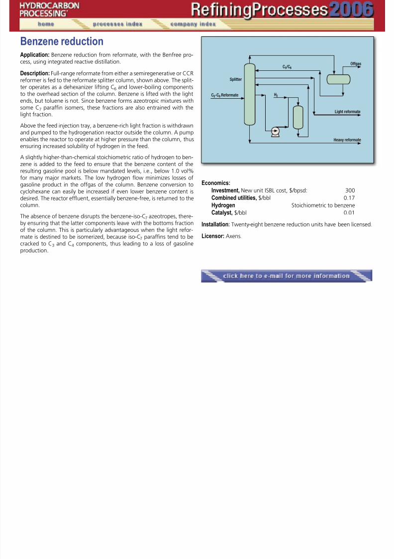
Benzene reductionApplication: Benzene reduction from reformate, with the Benfree pro-cess, using integrated reactive distillation.
Description: Full-range reformate from either a semiregenerative or CCRreformer is fed to the reformate splitter column, shown above. The split-ter operates as a dehexanizer lifting C6 and lower-boiling componentsto the overhead section of the column. Benzene is lifted with the lightends, but toluene is not. Since benzene forms azeotropic mixtures withsome C7 paraffin isomers, these fractions are also entrained with thelight fraction.
Above the feed injection tray, a benzene-rich light fraction is withdrawnand pumped to the hydrogenation reactor outside the column. A pumpenables the reactor to operate at higher pressure than the column, thusensuring increased solubility of hydrogen in the feed.
A slightly higher-than-chemical stoichiometric ratio of hydrogen to ben-zene is added to the feed to ensure that the benzene content of theresulting gasoline pool is below mandated levels, i.e., below 1.0 vol%for many major markets. The low hydrogen flow minimizes losses ofgasoline product in the offgas of the column. Benzene conversion tocyclohexane can easily be increased if even lower benzene content isdesired. The reactor effluent, essentially benzene-free, is returned to thecolumn.
The absence of benzene disrupts the benzene-iso-C7 azeotropes, there-by ensuring that the latter components leave with the bottoms fractionof the column. This is particularly advantageous when the light refor-mate is destined to be isomerized, because iso-C7 paraffins tend to becracked to C3 and C4 components, thus leading to a loss of gasolineproduction.
Economics:
Investment, New unit ISBL cost, $/bpsd: 300
Combined utilities, $/bbl 0.17
Hydrogen Stoichiometric to benzene
Catalyst, $/bbl 0.01
Installation: Twenty-eight benzene reduction units have been licensed.
Licensor: Axens.
�

7/18/2019 Refining Processes Handbook 2006
http://slidepdf.com/reader/full/refining-processes-handbook-2006 52/222
BiodieselApplication: Consumption of primary energy has risen substantially inrecent years, and greenhouse gases (GHG) emissions have increased by
a substantial amount. To counter this trend, there is a global strong em-phasis on regenerative energy such as biofuels to effectively reduce oravoid such emissions.
Description: The Lurgi biodiesel process is centered on the transesterifi-cation of different raw materials to methyl ester using methanol in thepresence of a catalyst. In principle, most edible oils and fats — both veg-etable and animal sources— can be transesterified if suitably prepared.
Transesterification is based on the chemical reaction of triglycerideswith methanol to methyl ester and glycerine in the presence of an alka-
line catalyst. The reaction occurs in two mixer-settler units. The actualconversion occurs in the mixers. The separation of methyl ester as thelight phase and glycerine water as the heavy phase occurs in the set-tlers due to the insolubility of both products. Byproduct componentsare removed from the methyl ester in the downstream washing stage,which operates in a counter-current mode. After a final drying step un-der vacuum, the biodiesel is ready for use.
Any residual methanol contained in the glycerine water is removedin a rectification column. In this unit operation, the methanol has a puri-ty, which is suitable for recycling back to process. For further refinement
of the glycerine water, optional steps are available such as chemicaltreatment, evaporation, distillation and bleaching to either deliver crudeglycerine at approximately 80% concentration or pharmaceutical-gradeglycerine at >99.7% purity.
Economics: The (approximate) consumption figures—without glycerinedistillation and bleaching—stated below are valid for the production ofone ton of rapeseed methyl ester at continuous operation and nominalcapacity.
Steam, kg 320
Water, cooling water (t = 10°C), m3 25Electrical energy, kWh 12
Methanol, kg 96Catalyst (Na-Methylate 100%), kg 5Hydrochloric Acid (37%), kg 10
Caustic soda (50%), kg 1.5Nitrogen, Nm3 1
Installation: Lurgi has been building biodiesel plants for 20 years. Only inthe last five years, Lurgi has contracted more than 40 plants for the pro-duction of biodiesel with capacities ranging from 30,000 to 200,000 tpy.
Licensors: Lurgi AG.
�

7/18/2019 Refining Processes Handbook 2006
http://slidepdf.com/reader/full/refining-processes-handbook-2006 53/222
Catalytic reformingApplication: Upgrade various types of naphtha to produce high-octanereformate, BTX and LPG.
Description: Two different designs are offered. One design is conventionalwhere the catalyst is regenerated in place at the end of each cycle. Oper-ating normally in a pressure range of 12 to 25 kg /cm2 (170 to 350 psig)and with low pressure drop in the hydrogen loop, the product is 90 to 100RONC. With its higher selectivity, trimetallic catalysts RG582 and RG682make an excellent catalyst replacement for semi-regenerative reformers.
The second, the advanced Octanizing process, uses continuous cata-lyst regeneration allowing operating pressures as low as 3.5 kg /cm 2 (50psig). This is made possible by smooth-flowing moving bed reactors (1–3)
which use a highly stable and selective catalyst suitable for continuousregeneration (4). Main features of Axens’ regenerative technology are:
• Side-by-side reactor arrangement, which is very easy to erect andconsequently leads to low investment cost.
• The Regen C2 catalyst regeneration system featuring the dry burnloop, completely restores the catalyst activity while maintaining itsspecific area for more than 600 cycles.
Finally, with the new CR401 (gasoline mode) and AR501 (aromaticsproduction) catalysts specifically developed for ultra-low operating pres-sure and the very effective catalyst regeneration system, refiners operat-
ing Octanizing or Aromizing processes can obtain the highest hydrogen,C5+ and aromatics yields over the entire catalyst life.
Yields: Typical for a 90°C to 170°C (176°F to 338°F) cut from light Ara-
bian feedstock: Conventional OctanizingOper. press., kg /cm2 10 –15 <5Yield, wt% of feed:Hydrogen 2.8 3.8
C5+ 83 88 RONC 100 102
MONC 89 90.5
Economics:
Investment: Basis 25,000 bpsd continuous Octanizing unit, batterylimits, erected cost, US$ per bpsd 1,800
Utilities: typical per bbl feed:Fuel, 103 kcal 65Electricity, kWh 0.96Steam, net, HP, kg 12.5Water, boiler feed, m3 0.03
Installation: Of 130 units licensed, 75 units are designed with continu-ous regeneration technology capability.
Reference: “Octanizing reformer options to optimize existing assets,”
NPRA Annual Meeting, March 15 –17, 2005, San Francisco.
�
�
Continued
Catalytic reforming, continued

7/18/2019 Refining Processes Handbook 2006
http://slidepdf.com/reader/full/refining-processes-handbook-2006 54/222
“Fixed Bed Reformer Revamp Solutions for Gasoline Pool Improve-ment,” Petroleum Technology Quarterly, Summer 2000.
“Increase reformer performance through catalytic solutions,” Sev-enth ERTC, November 2002, Paris.
“Squeezing the most out of fixed-bed reactors,” Hart Show Special,NPRA 2003 Annual.
Licensor: Axens.

7/18/2019 Refining Processes Handbook 2006
http://slidepdf.com/reader/full/refining-processes-handbook-2006 55/222
Catalytic dewaxingApplication: Use the ExxonMobil Selective Catalytic Dewaxing (MSDW)process to make high VI lube base stock.
Products: High VI / low-aromatics lube base oils (light neutral throughbright stocks). Byproducts include fuel gas, naphtha and low-pour diesel.
Description: MSDW is targeted for hydrocracked or severely hydrotreatedstocks. The improved selectivity of MSDW for the highly isoparaffinic-lubecomponents results in higher lube yields and VIs. The process uses mul-tiple catalyst systems with multiple reactors. Internals are proprietary (theSpider Vortex Quench Zone technology is used). Feed and recycle gasesare preheated and contact the catalyst in a down-flow-fixed-bed reactor.Reactor effluent is cooled, and the remaining aromatics are saturated in apost-treat reactor. The process can be integrated into a lube hydrocrackeror lube hydrotreater. Post-fractionation is targeted for client needs.
Operating conditions:Temperatures, ° F 550 – 800Hydrogen partial pressures, psig 500 – 2,500LHSV 0.4 – 3.0Conversion depends on feed wax contentPour point reduction as needed.
Yields: Light neutral Heavy neutralLube yield, wt% 94.5 96.5C1– C4, wt% 1.5 1.0C5– 400°F, wt% 2.7 1.8400°F – Lube, wt% 1.5 1.0H2 cons, scf / bbl 100 – 300 100 – 300
Economics: $3,000 – 5,500 per bpsd installed cost (US Gulf Coast).
Installation: Eight units are operating and four are in design.
Licensor: ExxonMobil Research and Engineering Co.
�

7/18/2019 Refining Processes Handbook 2006
http://slidepdf.com/reader/full/refining-processes-handbook-2006 56/222
Catalytic reformingApplication: Increase the octane of straight-run or cracked naphthas forgasoline production.
Products: High-octane gasoline and hydrogen-rich gas. Byproducts maybe LPG, fuel gas and steam.
Description: Semi-regenerative multibed reforming over platinum or bi-metallic catalysts. Hydrogen recycled to reactors at the rate of 3 mols / mol to 7 mols /mol of feed. Straight-run and /or cracked feeds are typi-cally hydrotreated, but low-sulfur feeds (<10 ppm) may be reformedwithout hydrotreatment.
Operating conditions: 875°F to 1,000°F and 150 psig to 400 psig reac-
tor conditions.
Yields: Depend on feed characteristics, product octane and reactor pres-sure. The following yields are one example. The feed contains 51.4%paraffins, 41.5% naphthenes and 7.1% aromatics, and boils from 208°Fto 375°F (ASTM D86). Product octane is 99.7 RONC and average reactorpressure is 200 psig.
Component wt% vol% H2 2.3 1,150 scf/bbl C1 1.1 — C2 1.8 — C3 3.2 — iC4 1.6 — nC4 2.3 — C5+ 87.1 — LPG — 3.7 Reformate — 83.2
Economics: Utilities, (per bbl feed) Fuel, 103 Btu release 275
Electricity, kWh 7.2 Water, cooling (20°F rise), gal 216 Steam produced (175 psig sat), lb 100
Licensor: CB&I Howe-Baker.
�
�

7/18/2019 Refining Processes Handbook 2006
http://slidepdf.com/reader/full/refining-processes-handbook-2006 57/222
Catalytic reformingApplication: The CCR Platforming process is used throughout the worldin the petroleum and petrochemical industries. It produces feed for an
aromatics complex or a high-octane gasoline blending product and asignificant amount of hydrogen.
Description: Hydrotreated naphtha feed is combined with recycle hy-drogen gas and heat exchanged against reactor effluent. The combinedfeed is then raised to reaction temperature in the charge heater and sentto the reactor section.
Radial-flow reactors are arranged in a vertical stack. The predomi-nant reactions are endothermic; so an interheater is used between eachreactor to reheat the charge to reaction temperature. The effluent from
the last reactor is heat exchanged against combined feed, cooled andsplit into vapor and liquid products in a separator. The vapor phase ishydrogen-rich. A portion of the gas is compressed and recycled back tothe reactors. The net hydrogen-rich gas is compressed and charged to-gether with the separator liquid phase to the product recovery section.This section is engineered to provide optimum performance.
Catalyst flows vertically by gravity down the reactor stack. Overtime, coke builds up on the catalyst at reaction conditions. Partially de-activated catalyst is continually withdrawn from the bottom of the reac-tor stack and transferred to the CCR regenerator.
Installation: UOP commercialized the CCR Platforming process in 1971and now has commissioned more than 180 units (more than 3.9 millionbpd of capacity) with another 30 in various stages of design, construc-tion and commissioning.
Efficiency/product quality: Commercial onstream efficiencies of morethan 95% are routinely achieved in CCR Platforming units.
Licensor: UOP LLC.
�

7/18/2019 Refining Processes Handbook 2006
http://slidepdf.com/reader/full/refining-processes-handbook-2006 58/222
CokingApplication: Conversion of atmospheric and vacuum residuals, hydro-treated and hydrocracked resids, visbroken resids, asphalt, pyrolysis tar,
decant oil, coal tar, pitch, solvent-refined and Athabasca bitumen.Description: Feedstock is introduced (after heat exchange) to the bot-tom of the coker fractionator (1) where it mixes with condensed recycle.The mixture is pumped through the coker heater (2) where the desiredcoking temperature is achieved, to one of two coke drums (3). Steamor boiler feedwater is injected into the heater tubes to prevent coking inthe furnace tubes. Coke drum overhead vapors flow to the fractionator(1) where they are separated into an overhead stream containing thewet gas, LPG and naphtha; two gas oil sidestreams; and the recycle that
rejoins the feed.The overhead stream is sent to a vapor recovery unit (4) where theindividual product streams are separated. The coke that forms in one ofat least two (parallel connected) drums is then removed using high-pres-sure water. The plant also includes a blow-down system, coke handlingand a water recovery system.
Operating conditions:Heater outlet temperature, °F 900 –950Coke drum pressure, psig 15 –90
Recycle ratio, vol/vol feed, % 0 –100 Yields:
Vacuum residue of
Middle East hydrotreated Coal tar
Feedstock vac. residue bottoms pitchGravity, °API 7.4 1.3 –21.0Sulfur, wt% 4.2 2.3 0.5
Conradson
carbon, wt% 20.0 27.6 4 8
Products, wt% Gas + LPG 7.9 9.0 3.9Naphtha 12.6 11.1 —
Gas oils 50.8 44.0 31.0Coke 28.7 35.9 65.1
Economics:
Investment (basis: 20,000 bpsd straight-run vacuum residue feed,US Gulf Coast 2006, fuel-grade coke, includes vapor recovery), US$per bpsd (typical) 6,000
�
�
�
Continued
Coking, continued

7/18/2019 Refining Processes Handbook 2006
http://slidepdf.com/reader/full/refining-processes-handbook-2006 59/222
Economics (continued):
Utilities, typical/bbl of feed:Fuel, 103 Btu 123Electricity, kWh 3.6Steam (exported), lb 1Water, cooling, gal 58
Boiler feedwater, lbs 38Condensate (exported), lbs 24
Installation: More than 60 units.
Reference: Mallik, R. and G. Hamilton, “Delayed coker design consid-erations and project execution,” NPRA 2002 Annual Meeting, March17–19, 2002.
Licensor: ABB Lummus Global.

7/18/2019 Refining Processes Handbook 2006
http://slidepdf.com/reader/full/refining-processes-handbook-2006 60/222
CokingApplication: Upgrading of petroleum residues (vacuum residue, bitumen,solvent-deasphalter pitch and fuel oil) to more valuable liquid products
(LPG, naphtha, distillate and gas oil). Fuel gas and petroleum coke arealso produced.
Description: The delayed coking process is a thermal process and con-sists of fired heater(s), coke drums and main fractionator. The crackingand coking reactions are initiated in the fired heater under controlledtime-temperature-pressure conditions. The reactions continue as theprocess stream moves to the coke drums. Being highly endothermic,the coking-reaction rate drops dramatically as coke-drum temperaturedecreases. Coke is deposited in the coke drums. The vapor is routed to
the fractionator, where it is condensed and fractionated into productstreams—typically fuel gas, LPG, naphtha, distillate and gas oil.When one of the pair of coke drums is full of coke, the heater outlet
stream is directed to the other coke drum. The full drum is taken offline,cooled with steam and water and opened. The coke is removed by hy-draulic cutting. The empty drum is then closed, warmed-up and madeready to receive feed while the other drum becomes full.
ConocoPhillips ThruPlus Delayed Coking Technology provides sev-eral advantages:
• Experienced owner-operator. More coke has been processed
by ConocoPhillips’ ThruPlus Delayed Coking Technology than by anyother competing process. The company has more than 50+ years ex-perience and today owns and operates 17 delayed cokers worldwide,with a combined capacity of more than 650,000 bpd. First licensing ourThruPlus Delayed Coking Technology in 1981, there are now 31 installa-tions worldwide, with a combined capacity of 1.1 million bpd and morecoming online in the US, Canada, and Brazil.
• Robust coke drum design. Drums designed to ConocoPhillips’specifications provide long operating service life—more than 20 yearswithout severe bulging or cracking—even when run on short drum cy-cles. The key is understanding drum fatigue at elevated temperatures.We do understand, and we design accordingly.
• Optimum heater design and operation. The proprietary designmethodology minimizes the conditions that cause coke deposits in theheater tubes. When combined with ConocoPhillips’ patented distillate
recycle technology, the result is maximum furnace run-length and im-proved liquid yields.
• Highly reliable coke handling system. The sloped concretewall and pit-pad system allows space for an entire drum of coke to becut without moving any of it. This allows the process side to operate atfull capacity, even if there is an issue with the coke handling system. Thesloped wall also improves safety and requires little maintenance over thelife of the unit.
• Short coke drum cycle time. We push the limits of reducingcycle times, running sustained 10-hour cycles, producing both anode
and fuel coke. Success in safely reducing cycle time requires a thoroughunderstanding of each phase of the cycle and the process. Since we’ve
�

7/18/2019 Refining Processes Handbook 2006
http://slidepdf.com/reader/full/refining-processes-handbook-2006 61/222

7/18/2019 Refining Processes Handbook 2006
http://slidepdf.com/reader/full/refining-processes-handbook-2006 62/222
CokingApplication: Upgrade residues to lighter hydrocarbon fractions using theSelective Yield Delayed Coking (SYDEC) process.
Description: Charge is fed directly to the fractionator (1) where it com-bines with recycle and is pumped to the coker heater. The mixture isheated to coking temperature, causing partial vaporization and mildcracking. The vapor-liquid mix enters a coke drum (2 or 3) for furthercracking. Drum overhead enters the fractionator (1) to be separated intogas, naphtha, and light and heavy gas oils. Gas and naphtha enter thevapor recovery unit (VRU)(4). There are at least two coking drums, onecoking while the other is decoked using high-pressure water jets. Thecoking unit also includes a coke handling, coke cutting, water recovery
and blowdown system. Vent gas from the blowdown system is recov-ered in the VRU.
Operating conditions: Typical ranges are:Heater outlet temperature, ºF 900 – 950Coke drum pressure, psig 15 – 100Recycle ratio, equiv. fresh feed 0 – 1.0Increased coking temperature decreases coke production; increases
liquid yield and gas oil end point. Increasing pressure and/or recycle ra-tio increases gas and coke make, decreases liquid yield and gas oil end
point. Yields:
Operation:Products, wt% Max dist. Anode coke Needle cokeGas 8.7 8.4 9.8Naphtha 14.0 21.6 8.4Gas oil 48.3 43.8 41.6Coke 29.3 26.2 40.2
Economics:Investment (basis 65,000 –10,000 bpsd) 2Q 2005 US Gulf), $ per bpsd 3,000 –5,200
Utilities, typical per bbl feed: Fuel, 103 Btu 120 Electricity, kWh 3 Steam (exported), lb 35 Water, cooling, gal 36
Installations: Currently, 52 delayed cokers are installed worldwide witha total installed capacity over 2.5 million bpsd
References: Handbook of Petroleum Refining Processes, Third Ed., Mc-Graw-Hill, pp. 12.33 –12.89.
“Delayed coking revamps,” Hydrocarbon Processing, September 2004.“Residue upgrading with SYDEC Delayed Coking: Benefits & Eco-
nomics,” AIChE Spring National Meeting, April 23–27, 2006, Orlando.“Upgrade refinery residuals into value-added products,” Hydrocar-
bon Processing, June 2006.
Licensor: Foster Wheeler/UOP LLC.
�
�

7/18/2019 Refining Processes Handbook 2006
http://slidepdf.com/reader/full/refining-processes-handbook-2006 63/222
Coking, fluidApplication: Continuous fluid, bed coking technology to convert heavyhydrocarbons (vacuum residuum, extra heavy oil or bitumen) to full-range lighter liquid products and fluid coke. Product coke can be soldas fuel or burned in an integrated fluid bed boiler to produce steam andpower.
Products: Liquid products can be upgraded through conventionalhydrotreating. Fluid coke is widely used as a solid fuel, with particularadvantages in cement kilns and in fluid-bed boilers.
Description: Feed (typically 1,050°F+ vacuum resid) enters the scrubber(1) for heat exchange with reactor overhead effluent vapors. The scrub-ber typically cuts 975°F+ higher boiling reactor effluent hydrocarbons
for recycle back to the reactor with fresh feed. Alternative scrubber con-figurations provide process flexibility by integrating the recycle streamwith the VPS or by operating once-through which produces higher liq-uid yields. Lighter overhead vapors from the scrubber are sent to con-ventional fractionation and light ends recovery. In the reactor (2), feedis thermally cracked to a full range of lighter products and coke.
The heat for the thermal cracking reactions is supplied by circulatingcoke between the burner (3) and reactor (2). About 20% of the cokeis burned with air to supply process heat requirements, eliminating the
need for an external fuel supply. The rest of the coke is withdrawn andeither sold as a product or burned in a fluid bed boiler. Properties of thefluid coke enable ease of transport and direct use in fuel applications,including stand alone or integrated cogeneration facilities.
Yields: Example, typical Middle East vacuum resid (~25 wt% Concar-bon, ~5 wt% sulfur): Recycle Once-Through Light ends, wt% 11.8 10.4 Naphtha (C5-350°F), wt% 11.5 9.5
Distillate (350 – 650°F), wt% 14.5 13.1 Heavy gas oil (650°F+), wt% 32.1 39.7
C5+ liquids, wt% 58.1 62.3
Net product coke, wt % 25.7 23.9
Coke consumed for heat, wt% 4.4 3.4Investment: TPC, US Gulf Coast, 2Q 2003 estimate including gas pro-cessing, coke handling and wet gas scrubbing for removing SOx fromthe burner overhead
Capital investment, $/bp/sd 3,300
Competitive advantages:• Single train capacities >100 Mbpsd; greater than other processes• Process wide range of feeds, especially high metals, sulfur and CCR• Internally heat integrated, minimal use of fuel gas, and lower coke
production than delayed coking
START
Reactor productsto fractionator
Net coke
1
2
3
Airblower
AirHot
cokeColdcoke
Flue gas to CO boiler
Continued
Coking, fluid, continued

7/18/2019 Refining Processes Handbook 2006
http://slidepdf.com/reader/full/refining-processes-handbook-2006 64/222
• Lower investment and better economy of scale than delayed cok-ing
• Efficient integration with fluid bed boilers for cogeneration ofsteam and electric power.
Licensor: ExxonMobil Research and Engineering Co.

7/18/2019 Refining Processes Handbook 2006
http://slidepdf.com/reader/full/refining-processes-handbook-2006 65/222
Coking, flexiApplication: Continuous fluid-bed coking technology to convert heavy
hydrocarbons (vacuum residuum, extra heavy oil or bitumen) to full-range lighter liquid products and Flexigas—a valuable lower Btu fuelgas. Applicable for complete conversion of resid in refineries with lim-ited outlets for coke, for heavy feed conversion at the resource, andlocations where low-cost clean fuel is needed or where natural gas hashigh value.
Products: Liquid products can be upgraded through conventionalhydrotreating. Clean Flexigas with <10 vppm H2S can be burned in fur-naces or boilers, replacing fuel oil, fuel gas or natural gasfuels.
Description: FLEXICOKING has essentially the same reactor (1)/scrubber(2) sections as FLUID COKING, and also has the same process flexibilityoptions: recycle, once-through and VPS integrated.
Process heat for the coking and gasification reactions is suppliedby circulating hot coke between the heater (3) the reactor (2), and thegasifier (4). Coke reacts with air and steam in the gasifier (4) to produceheat and lower BTU gas that is cleaned with FLEXSORB hinder aminetreating to <10 vppm of H2S. About 97% of the coke generated is con-sumed in the process; a small amount of purge coke is withdrawn from
the heater (3) and fines system (5), which can be burned in cement kilnsor used for vanadium recovery. Partial gasification/coke withdrawal andoxygen-enrichment can be used to provide additional process flexibility.
Yields: Example, typical Middle East vacuum resid (~25 wt% Concar-bon, ~5 wt% sulfur):
Recycle Once-through Light ends, (C4 ),wt% 11.8 10.4 Naphtha (C5-350°F), wt% 11.5 9.5 Distillate (350 – 650°F), wt% 14.5 13.1
Heavy gas oil (650°F+), wt% 32.1 39.7 C5+ Liquids, wt% 58.1 62.3
Purge coke, wt% ~1 ~1 Flexigas, MBtu/kbbl of feed 1,200 1,100
Investment: TPC, US Gulf Coast, 2Q03 estimate including gas process-ing, coke handling, Flexigas treating and distribution
Capital investment, $/bp/sd 4,700
Competitive advantages:• Fully continuous commercially proven integrated fluid bed coking
and fluid bed gasification process that produces valuable liquid productsand gaseous fuels.
• Low value coke is converted in the process to clean product Flexi-
gas fuel gas for use within the refinery or by nearby third-party powerplants or other consumers.
START
Reactor productsto fractionator
Low heatingvalue coke gas
1
2
3 4
5
5
Airblower
Steam
Cokefines
Sourwater
Directcontactcooler
Steamgeneration
Tertiary cyclones
Air
Hotcoke
Coldcoke
Continued
Coking, flexi, continued

7/18/2019 Refining Processes Handbook 2006
http://slidepdf.com/reader/full/refining-processes-handbook-2006 66/222
• Particularly attractive for SAGD tar sands upgrading with large fuelrequirements. Much lower investment and more reliable than delayedcoking plus partial oxidation or direct gasification of solids or heavyfeeds.
Licensor: ExxonMobil Research and Engineering Co.

7/18/2019 Refining Processes Handbook 2006
http://slidepdf.com/reader/full/refining-processes-handbook-2006 67/222
Crude distillationApplication: Separates and recovers the relatively lighter fractions (e.g.,naphtha, kerosine, diesel and cracking stock) from a fresh crude oil charge.The vacuum flasher processes the crude distillation bottoms to producean increased yield of liquid distillates and a heavy residual material.
Description: The charge is preheated (1), desalted (2) and directed to apreheat train (3) where it recovers heat from product and reflux streams.The typical crude fired heater (4) inlet temperature is on the order of550 ° F, while the outlet temperature is on the order of 675°F to 725°F.Heater effluent then enters a crude distillation column (5) where lightnaphtha is drawn off the tower overhead (6); heavy naphtha, kerosine,diesel and cracking stock are sidestream drawoffs. External reflux forthe tower is provided by pumparound streams (7–10). The atmosphericresidue is charged to a fired heater (11) where the typical outlet tem-perature is on the order of 725 °F to 775°F.
From the heater outlet, the stream is fed into a vacuum tower(12), where the distillate is condensed in two sections and withdrawnas two sidestreams. The two sidestreams are combined to form crack-ing feedstock. An asphalt base stock is pumped from the bottom ofthe tower. Two circulating reflux streams serve as heat removal mediafor the tower.
Yields: Typical for Merey crude oil:
Crude unit products wt% °API Pour, °FOverhead & naphtha 6.2 58.0 — Kerosine 4.5 41.4 – 85 Diesel 18.0 30.0 – 10 Gas oil 3.9 24.0 20 Lt. vac. gas oil 2.6 23.4 35 Hvy. vac. gas oil 10.9 19.5 85 Vac. bottoms 53.9 5.8 (120)*
Total 100.0 8.7 85
*Softening point, °FNote: Crude unit feed is 2.19 wt% sulfur. Vacuum unit feed is 2.91 wt% sulfur.
Economics:
Investment ( basis: 100,000–50,000 bpsd,2nd Q, 2005, US Gulf ), $ per bpsd 900 – 1,400
Utility requirements, typical per bbl fresh feed
Steam, lb 24Fuel (liberated), 103 Btu ( 80 – 120 )Power, kWh 0.6Water, cooling, gal 300 – 400
Installation: Foster Wheeler has designed and constructed crude unitshaving a total crude capacity in excess of 15 MMbpsd.
Reference: Encyclopedia of Chemical Processing and Design, Marcel-Dekker, 1997, pp. 230 – 249.
Licensor: Foster Wheeler.
11
START
Flash gas
Light naphtha
Heavy naphthaKerosine
Diesel
Cracker feed
To vac. system
Lt. vac. gas oil
Hvy. vac.
gas oil
Vac. gas oil
(cracker feed)
Asphalt
Stm.Stm.
34
5
6
7
8
9
10
2
1
Stm.
Crude
12

7/18/2019 Refining Processes Handbook 2006
http://slidepdf.com/reader/full/refining-processes-handbook-2006 68/222
Crude distillationApplication: The Shell Bulk CDU is a highly integrated concept. It sepa-rates the crude in long residue, waxy distillate, middle distillates and anaphtha minus fraction. Compared with stand-alone units, the overallintegration of a crude distillation unit (CDU), hydrodesulfurization unit(HDS), high vacuum unit (HVU) and a visbreaker (VBU) results in a 50%reduction in equipment count and significantly reduced operating costs.A prominent feature embedded in this design is the Shell deepflash HVUtechnology. This technology can also be provided in cost-effective pro-cess designs for both feedprep and lube oil HVUs as stand-alone units.For each application, tailor-made designs can be produced.
Description: The basic concept of the bulk CDU is the separation ofthe naphtha minus and the long residue from the middle distillatefraction, which is routed to the HDS. After desulfurization in the HDSunit, final product separation of the bulk middle distillate stream fromthe CDU takes place in the HDS fractionator (HDF), which consists of amain atmospheric fractionator with side strippers.
The long residue is routed hot to a feedprep HVU, which recoversthe waxy distillate fraction from long residue as the feedstock for acat-cracker or hydrocracker unit (HCU). Typical flashzone conditionsare 415°C and 24 mbara. The Shell design features a deentrainmentsection, spray sections to obtain a lower flashzone pressure, and a
VGO recovery section to recover up to 10 wt% as automotive diesel.The Shell furnace design prevents excessive cracking and enables a5-year run length between decoke.
Yields: Typical for Arabian light crude
Products wt, %Gas C1 – C4 0.7Gasoline C5 – 150°C 15.2Kerosine 150 – 250°C 17.4Gasoil (GO) 250 – 350°C 18.3
VGO 350 – 370°C 3.6Waxy distillate (WD) 370 – 575°C 28.8Residue 575°C+ 16.0
Economics: Due to the incorporation of Shell high capacity internalsand the deeply integrated designs, an attractive CAPEX reduction can beachieved. Investment costs are dependent on the required configurationand process objectives.
Installation: Over 100 Shell CDUs have been designed and operatedsince the early 1900s. Additionally, a total of some 50 HVU units havebeen built while a similar number has been debottlenecked, includingmany third-party designs of feedprep and lube oil HVUs.
Licensor: Shell Global Solutions International B.V.
� �
�

7/18/2019 Refining Processes Handbook 2006
http://slidepdf.com/reader/full/refining-processes-handbook-2006 69/222
Crude distillationApplication: The D2000 process is progressive distillation to minimize thetotal energy consumption required to separate crude oils or condensates
into hydrocarbon cuts, which number and properties are optimized to fitwith sophisticated refining schemes and future regulations. This process isapplied normally for new topping units or new integrated topping/vacu-um units but the concept can be used for debottlenecking purpose.
Products: This process is particularly suitable when more than twonaphtha cuts are to be produced. Typically the process is optimized toproduce three naphtha cuts or more, one or two kerosine cuts, two at-mospheric gas oil cuts, one vacuum gas oil cut, two vacuum distillatescuts, and one vacuum residue.
Description: The crude is preheated and desalted (1). It is fed to a firstdry reboiled pre-flash tower (2) and then to a wet pre-flash tower (3).The overhead products of the two pre-flash towers are then fraction-ated as required in a gas plant and rectification towers (4).
The topped crude typically reduced by 2 / 3 of the total naphtha cut isthen heated in a conventional heater and conventional topping column(5). If necessary the reduced crude is fractionated in one deep vacuumcolumn designed for a sharp fractionation between vacuum gas oil, twovacuum distillates (6) and a vacuum residue, which could be also a road
bitumen.Extensive use of pinch technology minimizes heat supplied by heat-ers and heat removed by air and water coolers.
This process is particularly suitable for large crude capacity from150,000 to 250,000 bpsd.
It is also available for condensates and light crudes progressive distil-lation with a slightly adapted scheme.
Economics:
Investment (basis 230,000 bpsd including atmospheric and
vacuum distillation, gas plant and rectification tower) $750 to$950 per bpsd (US Gulf Coast 2000).
Utility requirements, typical per bbl of crude feed: Fuel fired, 103 btu 50–65 Power, kWh 0.9–1.2
Steam 65 psig, lb 0–5 Water cooling, (15°C rise) gal 50–100
Total primary energy consumption: for Arabian Light or Russian Export Blend: 1.25 tons of fuel
per 100 tons of Crude for Arabian Heavy 1.15 tons of fuel
per 100 tons of Crude
Installation: Technip has designed and constructed one crude unit andone condensate unit with the D2000 concept. The latest revamp proj-
�
�
Continued
Crude distillation, continued

7/18/2019 Refining Processes Handbook 2006
http://slidepdf.com/reader/full/refining-processes-handbook-2006 70/222
ect currently in operation shows an increase of capacity of the existingcrude unit of 30% without heater addition.
Licensor: TOTAL and Technip.

7/18/2019 Refining Processes Handbook 2006
http://slidepdf.com/reader/full/refining-processes-handbook-2006 71/222
Crude topping unitsApplication: Crude topping units are typically installed in remote areasto provide fuel for local consumption, often for use at pipeline pumpingstations and at production facilities.
Products: Diesel is typically the desired product, but kerosine, turbinefuel and naphtha are also produced.
Description: Crude topping units comprise of four main sections: pre-heat/heat recovery section, fired heater, crude fractionation (distillation),and product cooling and accumulation. The fired heater provides heatfor the plant. Fuel for the heater can be residual products, offgas, natu-ral gas, distillate product, or combinations of these fuels, dependingon the installation. Heat integration reduces emissions and minimizes
process-energy requirements. Depending on the individual site, an elec-trostatic desalter may be required to prevent fouling and plugging, andcontrol corrosion in the fractionation section.
Crude topping units are modularized, which reduces constructioncost and complexity. Modular units also allow installation in remote ar-eas with minimal mobilization. These units are typically custom designedto meet individual customer requirements.
Crude topping units are self-contained, requiring few utilities for opera-tion. Utility packages, wastewater treatment facilities and other associated
offsites are often supplied, depending on the individual site requirements.Operating conditions:
Column pressure, psig 0 – 20Temperature, °F 550 – 650
Licensor: CB&I Howe-Baker.
�

7/18/2019 Refining Processes Handbook 2006
http://slidepdf.com/reader/full/refining-processes-handbook-2006 72/222
DeasphaltingApplication: Prepare quality feed for FCC units and hydrocrackers fromvacuum residue, and blending stocks for lube oil and asphalt manufac-turing.
Products: Deasphalted oil (DAO) for catalytic cracking and hydrocrackingfeedstocks, resins for specification asphalts, and pitch for specificationasphalts and residue fuels.
Description: Feed and light paraffinic solvent are mixed and thencharged to the extractor (1). The DAO and pitch phases, both containingsolvents, exit the extractor. The DAO and solvent mixture is separatedunder supercritical conditions (2). Both the pitch and DAO products arestripped of entrained solvent (3,4). A second extraction stage is utililized
if resins are to be produced.
Operating conditions: Typical ranges are:Solvent various blends of C3– C7 hydrocarbons includ-
ing light naphthasPressure, psig 300 – 600Temp., °F 120 – 450Solvent to oil ratio: 4/1 to 13/1
Yields:
Feed, type Lube oil Cracking stock Gravity, ºAPI 6.6 6.5 Sulfur, wt% 4.9 3.0 CCR, wt% 20.1 21.8 Visc, SSU@210ºF 7,300 8,720 Ni/V, wppm 29/100 46/125
DAO Yield, vol.% of feed 30 65 Gravity, ºAPI 20.3 15.1 Sulfur, wt% 2.7 2.2
CCR, wt% 1.4 6.2 Visc., SSU@210ºF 165 540
Ni/V, wppm 0.25/0.37 4.5/10.3Pitch
Softening point, R&B, ºF 149 240 Penetration@77ºF 12 0
Economics:Investment (basis: 40,000 –2,000 bpsd)
2Q 2005, US Gulf, $/bpsd 800 – 3,000Utilities, typical per bbl feed:
Fuel, 103 Btu (hot oil) 56 – 100 Electricity, kWh 1.9 – 2.0 Steam, 150 psig, lb 6 – 9 Water, cooling (25ºF rise), gal 10
�
�
�
�
Continued
Deasphalting, continued

7/18/2019 Refining Processes Handbook 2006
http://slidepdf.com/reader/full/refining-processes-handbook-2006 73/222
Installations: Over 50 units installed; this also includes both UOP andFoster Wheeler units originally licensed separately before merging thetechnologies in 1996.
References: Handbook of Petroleum Refining Processes, Third Ed., Mc-Graw Hill, 2003, pp. 10.37–10.61.
“When Solvent Deasphalting is the Most Appropriate Technologyfor Upgrading Residue,” International Downstream Technology Confer-ence, February 15 –16, 2006, London.
Licensor: Foster Wheeler/UOP LLC.

7/18/2019 Refining Processes Handbook 2006
http://slidepdf.com/reader/full/refining-processes-handbook-2006 74/222
Deep catalytic crackingApplication: Selective conversion of gasoil and paraffinic residual feed-stocks.
Products: C2– C5 olefins, aromatic-rich, high-octane gasoline anddistillate.
Description: DCC is a fluidized process for selectively cracking a widevariety of feedstocks to light olefins. Propylene yields over 24 wt% areachievable with paraffinic feeds. A traditional reactor/regenerator unitdesign uses a catalyst with physical properties similar to traditional FCCcatalyst. The DCC unit may be operated in two operational modes: max-imum propylene (Type I) or maximum iso-olefins (Type II).
Each operational mode utilizes unique catalyst as well as reaction
conditions. Maximum propylene DCC uses both riser and bed crackingat severe reactor conditions while Type II DDC uses only riser crackinglike a modern FCC unit at milder conditions.
The overall flow scheme of DCC is very similar to that of a conven-tional FCC. However, innovations in the areas of catalyst development,process variable selection and severity and gas plant design enablesthe DCC to produce significantly more olefins than FCC in a maximumolefins mode of operation.
This technology is quite suitable for revamps as well as grassroot
applications. Feed enters the unit through proprietary feed nozzles, asshown in the schematic. Integrating DCC technology into existing refin-eries as either a grassroots or revamp application can offer an attractiveopportunity to produce large quantities of light olefins.
In a market requiring both propylene and ethylene, use of boththermal and catalytic processes is essential, due to the fundamentaldifferences in the reaction mechanisms involved. The combination ofthermal and catalytic cracking mechanisms is the only way to increasetotal olefins from heavier feeds while meeting the need for an increasedpropylene to ethylene ratio. The integrated DCC/steam cracking com-
plex offers significant capital savings over a conventional stand-alonerefinery for propylene production.
Products (wt% of fresh feed) DCC Type I DCC Type II FCCEthylene 6.1 2.3 0.9Propylene 20.5 14.3 6.8Butylene 14.3 14.6 11.0 in which IC4
= 5.4 6.1 3.3
Amylene — 9.8 8.5 in which IC5
= — 6.5 4.3
Installation: Six units are currently operating in China and one in Thailand.Several more units are under design in China and one in Saudi Arabia.
Reference: Dharia, D., et al., “Increase light olefins production,” Hydro-carbon Processing, April 2004, pp. 61–66.
Licensor: Shaw Stone & Webster and Research Institute of PetroleumProcessing, Sinopec.

7/18/2019 Refining Processes Handbook 2006
http://slidepdf.com/reader/full/refining-processes-handbook-2006 75/222
Deep thermal conversionApplication: The Shell Deep Thermal Conversion process closes the gapbetween visbreaking and coking. The process yields a maximum of distil-lates by applying deep thermal conversion of the vacuum residue feedand by vacuum flashing the cracked residue. High-distillate yields areobtained, while still producing a stable liquid residual product, referredto as liquid coke. The liquid coke, not suitable for blending to commer-cial fuel, is used for speciality products, gasification and/or combustion,e.g., to generate power and/or hydrogen.
Description: The preheated short residue is charged to the heater (1)and from there to the soaker (2), where the deep conversion takes place.The conversion is maximized by controlling the operating temperatureand pressure. The soaker effluent is routed to a cyclone (3). The cycloneoverheads are charged to an atmospheric fractionator (4) to produce thedesired products like gas, LPG, naphtha, kero and gasoil. The cycloneand fractionator bottoms are subsequently routed to a vacuum flasher(5), which recovers additional gasoil and waxy distillate. The residual liq-uid coke is routed for further processing depending on the outlet.
Yields: Depend on feed type and product specifications.
Feed, vacuum residue Middle EastViscosity, cSt @100°C 615
Products in % wt. on feedGas 3.8Gasoline, ECP 165°C 8.2Gas oil, ECP 350°C 19Waxy distillate, ECP 520°C 22.8Residue ECP 520°C+ 46.2
Economics: The typical investment for a 25,000-bpd unit will be about$1,900 to $2,300/bbl installed, excluding treating facilities. (Basis: West-ern Europe, 2004.).
Utilities, typical consumption/production for a 25,000-bpd unit,dependent on configuration and a site’s marginal econmic values forsteam and fuel:
Fuel as fuel oil equivalent, bpd 417Power, MW 1.2Net steam production (18 bar), tpd 370
Installation: To date, six Shell Deep Thermal Conversion units have beenlicensed. In four cases, this has involved revamping an existing ShellSoaker Visbreaker unit. Post startup services and technical services forexisting units are available from Shell Global Solutions.
Reference: Hydrocarbon Engineering, September 2003.
Licensor: Shell Global Solutions International B.V. and ABB LummusGlobal B.V.
�
�

7/18/2019 Refining Processes Handbook 2006
http://slidepdf.com/reader/full/refining-processes-handbook-2006 76/222
DesulfurizationApplication: GT-BTXPlus addresses overall plant profitability by desul-furizing the FCC stream with no octane loss and decreased hydrogenconsumption by using a proprietary solvent in an extractive distillationsystem. This process also recovers valuable aromatics compounds. Olefin-rich raffinate can be recycled to FCC or to aromatizing unit.
Description: FCC gasoline, with endpoint up to 210 °C, is fed to the GT-BTXPlus unit, which extracts sulfur and aromatics from the hydrocarbonstream. The sulfur and aromatic components are processed in a conven-tional hydrotreater to convert the sulfur into H 2S. Because the portionof gasoline being hydrotreated is reduced in volume and free of olefins,hydrogen consumption and operating costs are greatly reduced. In con-trast, conventional desulfurization schemes process the majority of thegasoline through hydrotreating and caustic-washing units to eliminatethe sulfur. That method inevitably results in olefin saturation, octanedowngrade and yield loss.
GT-BTXPlus has these advantages:• Segregates and eliminates FCC-gasoline sulfur species to meet a
pool gasoline target of 20 ppm• Preserves more than 90% of the olefins from being hydrotreated
in the HDS unit; and thus, prevents significant octane loss andreduces hydrogen consumption
• Fewer components are sent to the HDS unit; consequently, asmaller HDS unit is needed and there is less yield loss
• High-purity BTX products can be produced from the aromatic-richextract stream after hydrotreating
• Olefin-rich raffinate stream (from the ED unit) can be recycled tothe FCC unit to increase the light olefin production.
FCC gasoline is fed to the extractive distillation column (EDC). Ina vapor-liquid operation, the solvent extracts the sulfur compoundsinto the bottoms of the column along with the aromatic components,while rejecting the olefins and nonaromatics into the overhead as raf-
finate. Nearly all of the nonaromatics, including olefins, are effectivelyseparated into the raffinate stream. The raffinate stream can be op-
tionally caustic washed before routing to the gasoline pool, or to aro-matizing unit.
Rich solvent, containing aromatics and sulfur compounds, is routedto the solvent recovery column, (SRC), where the hydrocarbons and sul-fur species are separated, and lean solvent is recovered in columns bot-
toms. The SRC overhead is hydrotreated by conventional means andused as desulfurized gasoline, or directed to an aromatics productionplant. Lean solvent from the SRC bottoms are treated and recycled backto the EDC.
Economics: Estimated installed cost of $1,000 / bpd of feed and produc-tion cost of $0.50 / bbl of feed for desulfurization and dearomatization.
Licensor: GTC Technology Inc.
�
�
�

7/18/2019 Refining Processes Handbook 2006
http://slidepdf.com/reader/full/refining-processes-handbook-2006 77/222
DewaxingApplication: Bechtel’s Dewaxing process is used to remove waxy com-ponents from lubrication base-oil streams to simultaneously meet de-sired low-temperature properties for dewaxed oils and produce slackwax as a byproduct.
Description: Waxy feedstock (raffinate, distillate or deasphalted oil) ismixed with a binary-solvent system and chilled in a very closely controlledmanner in scraped-surface double-pipe exchangers (1) and refrigeratedchillers (2) to form a wax/oil/solvent slurry.
The slurry is filtered through the primary filter stage (3) and dewaxedoil mixture is routed to the dewaxed oil recovery section (5) to separatesolvent from oil. Prior to solvent recovery, the primary filtrate is used tocool the feed/solvent mixture (1). Wax from the primary stage is slurriedwith cold solvent and filtered again in the repulp filter (4) to reduce theoil content to approximately 10%.
The repulp filtrate is reused as dilution solvent in the feed chillingtrain. The wax mixture is routed to a solvent-recovery section (6) to re-move solvent from the product streams (hard wax and soft wax). Therecovered solvent is collected, dried (7) and recycled back to the chillingand filtration sections.
Economics:
Investment (Basis: 7,000-bpsd feedratecapacity, 2006 US Gulf Coast), $/bpsd 11,200
Utilities, typical per bbl feed: Fuel, 103 Btu (absorbed) 160 Electricity, kWh 15 Steam, lb 35 Water, cooling (25°F rise), gal 1,100
Installation: Over 100 have been licensed and built.
Licensor: Bechtel Corp.
�
�

7/18/2019 Refining Processes Handbook 2006
http://slidepdf.com/reader/full/refining-processes-handbook-2006 78/222
DewaxingApplication: Selectively convert feedstock’s waxy molecules by isomeriza-tion in the presence of ISODEWAXING Catalysts. The products are high-quality base oils that can meet stringent cold flow properties.
Description: ISODEWAXING Catalysts are very special catalysts that con-vert feedstocks with waxy molecules (containing long, paraffinic chains)into two or three main branch isomers that have low-pour points. Theproduct also has low aromatics content. Typical feeds are: raffinates,slack wax, foots oil, hydrotreated VGO, hydrotreated DAO and uncon-verted oil from hydrocracking.
As shown in the simplified flow diagram, waxy feedstocks are mixedwith recycle hydrogen and fresh makeup hydrogen, heated and chargedto a reactor containing ISODEWAXING Catalyst (1). The effluent willhave a much lower pour point and, depending on the operating severity,the aromatics content is reduced by 50– 80% in the dewaxing reactor.
In a typical configuration, the effluent from a dewaxing reactor iscooled down and sent to a finishing reactor (2) where the remainingsingle ring and multiple ring aromatics are further saturated by the ISO-FINISHING Catalysts. The effluent is flashed in high-pressure and low-pressure separators (3, 4). Small amounts of light products are recoveredin a fractionation system (5).
Yields: The base oil yields strongly depend on the feedstocks. For a typi-cal low wax content feedstock, the base oil yield can be 90–95%. Higherwax feed will have a little lower base oil yield.
Economics:
Investment: This is a moderate investment process; for a typical sizeISODEWAXING/ISOFINISHING Unit, the capital for ISBLis about 6,000 $/bpsd.
Utilities: Typical per bbl feed: Power, kW 3.3Fuel , kcal 13.4 x 10³
Steam, superheated, required, kg 5.3Steam, saturated, produced, kg 2.4Water, cooling, kg 192
Chemical-hydrogen consumption, Nm3 /m3 oil 30~50
Installation: More than twelve units are in operation and six units are invarious stages of design or construction.
Reference: NPRA Annual Meeting, March 2005, San Francisco, PaperAM-05-39.
Licensor: Chevron Lummus Global LLC.
�
�

7/18/2019 Refining Processes Handbook 2006
http://slidepdf.com/reader/full/refining-processes-handbook-2006 79/222
Dewaxing/wax deoilingApplication: Bechtel’s Dewaxing/Wax Fractionation processes are usedto remove waxy components from lubrication base-oil streams to si-multaneously meet desired low-temperature properties for dewaxed oilsand produce hard wax as a premium byproduct.
Description: Bechtel’s two-stage solvent dewaxing process can be ex-panded to simultaneously produce hard wax by adding a third deoilingstage using the Wax Fractionation process. Waxy feedstock (raffinate,distillate or deasphalted oil) is mixed with a binary-solvent system andchilled in a very closely controlled manner in scraped-surface double-pipe exchangers (1) and refrigerated chillers (2) to form a wax/oil/solventslurry.
The slurry is filtered through the primary filter stage (3) and dewaxedoil mixture is routed to the dewaxed oil recovery section (6) to separatesolvent from oil. Prior to solvent recovery, the primary filtrate is used tocool the feed/solvent mixture (1).
Wax from the primary stage is slurried with cold solvent and filteredagain in the repulp filter (4) to reduce the oil content to approximately10%. The repulp filtrate is reused as dilution solvent in the feed chillingtrain. The low-oil content slack wax is warmed by mixing with warmsolvent to melt the low-melting-point waxes (soft wax) and is filtered ina third stage filtration (5) to separate the hard wax from the soft wax.
The hard and soft wax mixtures are each routed to solvent recovery sec-tions (7,8) to remove solvent from the product streams (hard wax andsoft wax). The recovered solvent is collected, dried (9) and recycled backto the chilling and filtration sections.
Economics:
Investment (Basis: 7,000-bpsd feedratecapacity, 2006 US Gulf Coast), $/bpsd 13,200
Utilities, typical per bbl feed: Fuel, 103 Btu (absorbed) 230 Electricity, kWh 25
Steam, lb 25 Water, cooling (25°F rise), gal 1,500
Installation: Seven in service.
Licensor: Bechtel Corp.
�
�

7/18/2019 Refining Processes Handbook 2006
http://slidepdf.com/reader/full/refining-processes-handbook-2006 80/222
Diesel—ultra-low-sulfur diesel (ULSD)Application: Topsøe ULSD process is designed to produce ultra-low-sulfurdiesel (ULSD) (5–50 wppm S) from cracked and straight-run distillates.By selecting the proper catalyst and operating conditions, the process
can be designed to produce 5 wppm S diesel at low reactor pressures(<500 psig) or at higher reactor pressure when products with improveddensity, cetane, and polyaromatics are required.
Description: Topsøe ULSD process is a hydrotreating process that com-bines Topsøe’s understanding of deep-desulfurization kinetics, high-ac-tivity catalyst, state-of-the-art reactor internal, and engineering exper-tise in the design of new and revamped ULSD units. The ULSD processcan be applied over a very wide range of reactor pressures.
Our highest activity BRIM catalyst is specifically formulated withhigh-desulfurization activity and stability at low reactor pressure (~ 500psig) to produce 5 wppm diesel. This catalyst is suitable for revampingexisting low-pressure hydrotreaters or in new units when minimizinghydrogen consumption.
The highest activity BRIM catalyst is suitable at higher pressure whensecondary objectives such as cetane improvement and density reductionare required. Topsøe offers a wide range of engineering deliverables tomeet the needs of the refiners. Our offerings include process scopingstudy, reactor design package, process design package, or engineering
design package.
Installation: Topsøe has licensed more than 50 ULSD hydrotreaters ofwhich more than 40 units are designed for less than 10 wppm sulfur inthe diesel. Our reactor internals are installed in more than 60 ULSD units.
References: Low, G., J. Townsend and T. Shooter, “Systematic approach for the
revamp of a low-pressure hydrotreater to produce 10-ppm, sulfur-freediesel at BP Conyton Refinery,” 7th ERTC, Paris, November 2002.
Sarup, B., M. Johansen, L. Skyum and B. Cooper, “ULSD Productionin Practice,” 9th ERTC, Prague, November 2004.
Hoekstra, G., V. Pradhan, K. Knudsen, P. Christensen, I. Vasalos andS. Vousvoukis, “ULSD: Ensuring the unit makes on-spec. product,” NPRAAnnual Meeting, Salt Lake City, March 2006.
Licensor: Haldor Topsøe A/S.
�
�

7/18/2019 Refining Processes Handbook 2006
http://slidepdf.com/reader/full/refining-processes-handbook-2006 81/222
Diesel upgradingApplication: Topsøe’s Diesel Upgrading process can be applied for im-provement of a variety of diesel properties, including reduction of dieselspecific gravity, reduction of T90 and T95 distillation (Back-end-shift),
reduction of aromatics, and improvements of cetane, cold-flow prop-erties, (pour point, clouds point, viscosity and CFPP) and diesel colorreduction (poly shift). Feeds can range from blends of straight-run andcracked gas oils up to heavy distillates, including light vacuum gas oil.
Description: Topsøe’s Diesel Upgrading process is a combination of treatingand upgrading. The technology combines state-of-the-art reactor internals,engineering expertise in quality design, high-activity treating catalyst andproprietary diesel upgrading catalyst. Every unit is individually designed toimprove the diesel property that requires upgrading. This is done by se-
lecting the optimum processing parameters, including unit pressure andLHSV and determining the appropriate Topsøe high-activity catalysts andplant lay-out. The process is suitable for new units or revamps of existinghydrotreating units.
In the reactor system, the treating section uses Topsøe’s high-activ-ity CoMo or NiMo catalyst, such as TK-575 BRIM or TK-576 BRIM, toremove feed impurities such as sulfur and nitrogen. These compoundslimit the downstream upgrading catalyst performance, and the purifiedstream is treated in the downstream upgrading reactor. Reactor catalyst
used in the application is dependent on the specific diesel property thatrequires upgrading. Reactor section is followed by separation and strip-ping/fractionation where final products are produced.
Like the conventional Topsøe hydrotreating process, the diesel up-grading process uses Topsøe’s graded-bed loading and high-efficiencypatented reactor internals to provide optimal reactor performance andcatalyst utilization. Topsøe’s high-efficiency internals are effective for awide range of liquid loading. Topsøe’s graded-bed technology and theuse of shape-optimized inert topping material and catalyst minimizethe pressure drop build-up, thereby reducing catalyst skimming require-
ments and ensuring long catalyst cycle lengths.
References: Patel, R., “How are refiners meeting the ultra-low-sulfurdiesel challenge?” NPRA Annual Meeting, San Antonio, March 2003.
Fuente, E., P. Christensen, and M. Johansen, “Options for meetingEU year 2005 fuels specifications,” 4th ERTC, November 1999.
Installations: A total of 16 units; six in Asia-Pacific region, one in theMiddle East, two in Europe and seven HDS/HDA units (see Hydrodearo-matization).
Licensor: Haldor Topsøe A/S.
�
�
�

7/18/2019 Refining Processes Handbook 2006
http://slidepdf.com/reader/full/refining-processes-handbook-2006 82/222
EthersApplication: Production of high-octane reformulated gasoline compo-nents (MTBE, ETBE, TAME and/or higher molecular-weight ethers) fromC1 to C2 alcohols and reactive hydrocarbons in C4 to C6 cuts.
Description: Different arrangements have been demonstrated depend-ing on the nature of the feeds. All use acid resins in the reaction section.The process includes alcohol purification (1), hydrocarbon purification(2), followed by the main reaction section. This main reactor (3) operatesunder adiabatic upflow conditions using an expanded-bed technologyand cooled recycle. Reactants are converted at moderate well-controlledtemperatures and moderate pressures, maximizing yield and catalyst life.The main effluents are purified for further applications or recycle.
More than 90% of the total per pass conversion occurs in the ex-panded-bed reactor. The effluent then flows to a reactive distillationsystem (4), Catacol. This system, operated like a conventional distillationcolumn, combines catalysis and distillation. The catalytic zones of theCatacol use fixed-bed arrangements of an inexpensive acidic resin cata-lyst that is available in bulk quantities and easy to load and unload.
The last part of the unit removes alcohol from the crude raffinateusing a conventional waterwash system (5) and a standard distillationcolumn (6).
Yields: Ether yields are not only highly dependent on the reactive olefins’content and the alcohol’s chemical structure, but also on operatinggoals: maximum ether production and/or high final raffinate purity (forinstance, for downstream 1-butene extraction) are achieved.
Economics: Plants and their operations are simple. The same inexpen-sive (purchased in bulk quantities) and long-lived, non-sophisticated cat-alysts are used in the main reactor section catalytic region of the Catacolcolumn, if any.
Installation: Over 25 units, including ETBE and TAME, have been licensed.Twenty-four units, including four Catacol units, are in operation.
Licensor: Axens.
�
�

7/18/2019 Refining Processes Handbook 2006
http://slidepdf.com/reader/full/refining-processes-handbook-2006 83/222
Ethers—ETBEApplication: The Uhde (Edeleanu) ETBE process combines ethanol andisobutene to produce the high-octane oxygenate ethyl tertiary butylether (ETBE).
Feeds: C4 cuts from steam cracker and FCC units with isobutene con-tents ranging from 12% to 30%.
Products: ETBE and other tertiary alkyl ethers are primarily used in gas-oline blending as an octane enhancer to improve hydrocarbon com-bustion efficiency. Moreover, blending of ETBE to the gasoline pool willlower vapor pressure (Rvp).
Description: The Uhde (Edeleanu) technology features a two-stage re-
actor system of which the first reactor is operated in the recycle mode.With this method, a slight expansion of the catalyst bed is achieved thatensures very uniform concentration profiles in the reactor and, mostimportant, avoids hot spot formation. Undesired side reactions, such asthe formation of di-ethyl ether (DEE), are minimized.
The reactor inlet temperature ranges from 50°C at start-of-run toabout 65°C at end-of-run conditions. One important feature of the two-stage system is that the catalyst can be replaced in each reactor sepa-rately, without shutting down the ETBE unit.
The catalyst used in this process is a cation-exchange resin and is available
from several manufacturers. Isobutene conversions of 94% are typical forFCC feedstocks. Higher conversions are attainable when processing steam-
cracker C4 cuts that contain isobutene concentrations of about 25%.ETBE is recovered as the bottoms product of the distillation unit. The
ethanol-rich C4 distillate is sent to the ethanol recovery section. Water isused to extract excess ethanol and recycle it back to process. At the topof the ethanol / water separation column, an ethanol / water azeotrope isrecycled to the reactor section. The isobutene-depleted C4 stream maybe sent to a raffinate stripper or to a molsieve-based unit to remove
oxygenates such as DEE, ETBE, ethanol and tert- butanol.
Utility requirements: (C4 feed containing 21% isobutene; per metricton of ETBE):
Steam, LP, kg 110Steam, MP, kg 1,000
Electricity, kWh 35Water, cooling, m3 24
Installation: The Uhde (Edeleanu) proprietary ETBE process has beensuccessfully applied in three refineries, converting existing MTBE units.Two other MTBE plants are in the conversion stage.
Licensor: Uhde GmbH.
�
�

7/18/2019 Refining Processes Handbook 2006
http://slidepdf.com/reader/full/refining-processes-handbook-2006 84/222
Ethers—MTBEApplication: The Uhde (Edeleanu) MTBE process combines methanoland isobutene to produce the high-octane oxygenate—methyl tertiarybutyl ether (MTBE).
Feeds: C4-cuts from steam cracker and FCC units with isobutene con-tents range from 12% to 30%.
Products: MTBE and other tertiary alkyl ethers are primarily used in gas-oline blending as an octane enhancer to improve hydrocarbon combus-tion efficiency.
Description: The technology features a two-stage reactor system ofwhich the first reactor is operated in the recycle mode. With this meth-od, a slight expansion of the catalyst bed is achieved which ensures veryuniform concentration profiles within the reactor and, most important,avoids hot spot formation. Undesired side reactions, such as the forma-tion of dimethyl ether (DME), are minimized.
The reactor inlet temperature ranges from 45°C at start-of-run toabout 60°C at end-of-run conditions. One important factor of the two-stage system is that the catalyst may be replaced in each reactor sepa-rately, without shutting down the MTBE unit.
The catalyst used in this process is a cation-exchange resin and isavailable from several catalyst manufacturers. Isobutene conversions of
97% are typical for FCC feedstocks. Higher conversions are attainablewhen processing steam-cracker C4 cuts that contain isobutene concen-trations of 25%.
MTBE is recovered as the bottoms product of the distillation unit.The methanol-rich C4 distillate is sent to the methanol-recovery section.Water is used to extract excess methanol and recycle it back to process.The isobutene-depleted C4 stream may be sent to a raffinate stripperor to a molsieve-based unit to remove other oxygenates such as DME,MTBE, methanol and tert-butanol.
Very high isobutene conversion, in excess of 99%, can be achieved
through a debutanizer column with structured packings containing ad-ditional catalyst. This reactive distillation technique is particularly suited
when the raffinate-stream from the MTBE unit will be used to producea high-purity butene-1 product.
For a C4 cut containing 22% isobutene, the isobutene conversionmay exceed 98% at a selectivity for MTBE of 99.5%.
Utility requirements, (C4 feed containing 21% isobutene; per metric tonof MTBE):
Steam, MP, kg 100 Electricity, kWh 35 Water, cooling, m3 15 Steam, LP, kg 900
Installation: The Uhde (Edeleanu) proprietary MTBE process has beensuccessfully applied in five refineries. The accumulated licensed capacityexceeds 1 MMtpy.
Licensor: Uhde GmbH.
�
�

7/18/2019 Refining Processes Handbook 2006
http://slidepdf.com/reader/full/refining-processes-handbook-2006 85/222
Flue gas denitrificationApplication: The Topsøe SCR DeNOx process removes NOx from fluegases through reactions with an ammonia-based reducing agent overa specially designed fixed-bed monolithic catalyst. By carefully select-ing the catalyst parameters, channel size and chemical composition, theprocess covers a wide range of operating conditions and flue-gas dustcontents and may be applied to practically all types of refinery units in-cluding furnaces, boilers, crackers and FCC units.
Products: The Topsøe SCR DeNOx converts NOx into inert nitrogen andwater vapor. The process may be designed for NOx reductions in excessof 95% and with an ammonia leakage of just a few ppm.
Description: The reducing agent such as ammonia or urea, aqueous or
pure, is injected into the flue gas stream in stoichiometric proportion tothe amount of NOx in the flue gas, controlled by measurement of fluegas flow and NOx concentration. The injection takes place in a grid overthe entire cross-section of the flue-gas duct to ensure a uniform distribu-tion of NOx and ammonia upstream the SCR catalyst vessel.
The process incorporates Topsøe’s well-proven corrugated mono-lithic DNX catalyst. DNX is manufactured in small units, which may becombined into larger modules to match any requirement in terms ofvessel dimensions and pressure drop, and in both horizontal and verticalvessel configurations.
The DNX catalyst is based on a fiber-reinforced ceramic carrier, whichgives a unique combination of a high strength and a high micro-poros-ity. The high micro-porosity provides a superior resistance to catalystpoisons and low weight. The fibers add flexibility to the catalyst so thatit can tolerate a wide range of heating and cooling rates.
Operating conditions: Typical operating conditions range from 300°C to500°C (570–930°F), up to 3 bar (44 psia) and up to 50 g/Nm3 of dust inthe flue gas.
Installation: More than 50 refinery units use Topsøe SCR DeNOx catalystand technology. The applications range from low-dust furnaces to high-dust FCC units and temperatures up to 500°C (930°F).
References: Damgaard, L., B. Widroth and M. Schröter: “Control refin-ery NOx with SCRs,” Hydrocarbon Processing, November 2004.
Licensor: Haldor Topsøe A/S.
�

7/18/2019 Refining Processes Handbook 2006
http://slidepdf.com/reader/full/refining-processes-handbook-2006 86/222
Flue gas desulfurization—SNOXApplication: The SNOX process treats boiler flue gases from the com-bustion of high-sulfur fuels, such as heavy residual oil and petroleumcoke. The SNOX process is a combination of the Topsøe WSA processand the Topsøe SCR DeNOx process. The process removes SO2, SO3 andNOx as well as dust. The sulfur is recovered in the form of concentratedcommercial-grade sulfuric acid. The SNOX process is distinctly differentfrom most other flue gas desulfurization processes in that its economyincreases with increasing sulfur content in the flue gas.
Description: Dust is removed from the flue gas by means of an electro-static precipitator or a bag filter. The flue gas is preheated in a gas/gasheat exchanger. Thereafter, it is further heated to approximately 400°Cand ammonia is added, before it enters the reactor, where two differentcatalysts are installed. The first catalyst makes the NOx react with ammo-nia to form N2 and water vapor, and the second catalyst makes the SO2
react with oxygen to form SO3. The second catalyst also removes anydust traces remaining. During the cooling in the gas/gas heat exchanger,most of the SO3 reacts with water vapor to form sulfuric acid vapor. Thesulfuric acid vapor is condensed via further cooling in the WSA con-denser, which is a heat exchanger with vertical glass tubes.
Concentrated commercial-grade sulfuric acid is collected in thebottom of the WSA condenser and is cooled and pumped to storage.
Cleaned flue gas leaves the WSA condenser at 100°C and can be sentto the stack without further treatment. The WSA condenser is cooled byatmospheric air. The cooling air can be used as preheated combustionair in the boiler. This process can achieve up to 98% sulfur removal andabout 96% NOx removal.
Other features of the SNOX process are:• No absorbent is applied• No waste products are produced. Besides dust removed from the
flue gas, the only products are cleaned flue gas and concentratedcommercial-grade sulfuric acid.
• High degree of heat efficiency• Modest utility consumption
• Attractive operating economy• Simple, reliable and flexible process.
Installation: Four SNOX units have been contracted for cleaning of a to-
tal of more than three million Nm3 / h of flue gas. Additionally, 50 WSAplants have been contracted. These are similar to SNOX plants, onlysmaller, and some without NOx removal, for other applications than fluegas cleaning.
Licensor: Haldor Topsøe A/S.
�

7/18/2019 Refining Processes Handbook 2006
http://slidepdf.com/reader/full/refining-processes-handbook-2006 87/222
Fluid catalytic crackingApplication: Selective conversion of a wide range of gas oils into high-value products. Typical feedstocks are virgin or hydrotreated gas oils butmay also include lube oil extract, coker gas oil and resid.
Products: High-octane gasoline, light olefins and distillate. Flexibility ofmode of operation allows for maximizing the most desirable product.The new commercially proven FCC/ Indmax technology selectively cracksmolecules of different sizes and shapes, thus maximizing light olefins(propylene and ethylene) production.
Description: The Lummus process incorporates an advanced reactionsystem, high-efficiency catalyst stripper and a mechanically robust,single-stage fast fluidized bed regenerator. Oil is injected into the
base of the riser via proprietary Micro-Jet feed injection nozzles (1).Catalyst and oil vapor flow upwards through a short-contact time,all-vertical riser (2) where raw oil feedstock is cracked under opti-mum conditions.
Reaction products exiting the riser are separated from the spentcatalyst in a patented, direct-coupled cyclone system (3). Productvapors are routed directly to fractionation, thereby eliminating non-selective, post-riser cracking and maintaining the optimum prod-uct yield slate. Spent catalyst containing only minute quantities ofhydrocarbon is discharged from the diplegs of the direct-coupled
cyclones into the cyclone containment vessel (4). The catalyst flowsdown into the stripper containing proprietary modular grid (MG)baffles (5).
Trace hydrocarbons entrained with spent catalyst are removedin the MG stripper using stripping steam. The MG stripper efficient-ly removes hydrocarbons at low steam rate. The net stripper vaporsare routed to the fractionator via specially designed vents in thedirect-coupled cyclones. Catalyst from the stripper flows down thespent-catalyst standpipe and through the slide valve (6). The spent
catalyst is then transported in dilute phase to the center of the re-generator (8) through a unique square-bend-spent catalyst transfer
line (7). This arrangement provides the lowest overall unit elevation.Catalyst is regenerated by efficient contacting with air for completecombustion of coke. For resid-containing feeds, the optional cata-lyst cooler is integrated with the regenerator. The resulting flue gasexits via cyclones (9) to energy recovery/flue gas treating. The hot
regenerated catalyst is withdrawn via an external withdrawal well(10). The well allows independent optimization of catalyst densityin the regenerated catalyst standpipe, maximizes slide valve (11)pressure drop and ensures stable catalyst flow back to the riser feedinjection zone.
The catalyst formulation can be tailored to maximize the mostdesired product. For example, the formulation for maximizing lightolefins (Indmax operation) is a multi-component mixture that pro-motes the selective cracking of molecules of different sizes andshapes to provide very high conversion and yield of light olefins.
�
Continued
Economics:
Fluid catalytic cracking, continued

7/18/2019 Refining Processes Handbook 2006
http://slidepdf.com/reader/full/refining-processes-handbook-2006 88/222
Economics:
Investment (basis: 30,000 bpsd including reaction/regenerationsystem and product recovery. Excluding offsites, power recoveryand flue gas scrubbing US Gulf Coast 2006.)$/bpsd (typical) 2,400–3,500
Utilities, typical per bbl fresh feed:
Electricity, kWh 0.8–1.0Steam, 600 psig (produced) 50–200Maintenance, % of investment per year 2–3
Installation: Fifteen grassroots units licensed. Twenty-eight units re-vamped, with five revamps in design stage.
Licensor: ABB Lummus Global.

7/18/2019 Refining Processes Handbook 2006
http://slidepdf.com/reader/full/refining-processes-handbook-2006 89/222
Fluid catalytic crackingApplication: FLEXICRACKING IIIR converts high-boiling hydrocarbons in-cluding residues, gas oils, lube extracts and/or deasphalted oils to highervalue products.
Products: Light olefins for gasoline processes and petrochemicals, LPG,blend stocks for high-octane gasoline, distillates and fuel oils.
Description: The FLEXICRACKING IIIR technology includes process de-sign, hardware details, special mechanical and safety features, controlsystems, flue gas processing options and a full range of technical servic-es and support. The reactor (1) incorporates many features to enhanceperformance, reliability and flexibility, including a riser (2) with patentedhigh-efficiency close-coupled riser termination (3), enhanced feed injec-
tion system (4) and efficient stripper design (5). The reactor design andoperation maximizes the selectivity of desired products, such as naphthaand propylene.
The technology uses an improved catalyst circulation system withadvanced control features, including cold-walled slide valves (6). Thesingle vessel regenerator (7) has proprietary process and mechanical fea-tures for maximum reliability and efficient air/catalyst distribution andcontacting (8). Either full or partial combustion is used. With increasingresidue processing and the need for additional heat balance control,partial burn operation with outboard CO combustion is possible, or KBR
dense phase catalyst cooler technology may be applied. The ExxonMobilwet gas scrubbing or the ExxonMobil-KBR Cyclofines TSS technologiescan meet flue gas emission requirements.
Yields: Typical examples:
Resid feed VGO + lube extracts VGO feed
mogas distillate mogas
operation operation operation
FeedGravity, °API 22.9 22.2 25.4Con carbon, wt% 3.9 0.7 0.4Quality 80% Atm. Resid 20% Lube Extracts 50% TBP – 794°F (Hydrotreated)
Product yieldsNaphtha, lv% ff 78.2 40.6 77.6(C4 / FBP) (C4 / 430°F) (C4 / 260°F) (C4 / 430°F)Mid Dist., lv% ff 13.7 49.5 19.2(IBP / FBP) (430 / 645°F) (260 / 745°F) (430 / 629°F)
�
�
Continued
Installation: More than 70 units with a design capacity of over 2 5-mil-
Fluid catalytic cracking, continued

7/18/2019 Refining Processes Handbook 2006
http://slidepdf.com/reader/full/refining-processes-handbook-2006 90/222
Installation: More than 70 units with a design capacity of over 2.5 million bpd fresh feed.
References: Ladwig, P. K., “Exxon FLEXICRACKING IIIR fluid catalyticcracking technology,” Handbook of Petroleum Refining Processes, Sec-ond Ed., R. A. Meyers, Ed., pp. 3.3–3.28.
Licensor: ExxonMobil Research and Engineering Co. and Kellogg Brown& Root, Inc. (KBR).

7/18/2019 Refining Processes Handbook 2006
http://slidepdf.com/reader/full/refining-processes-handbook-2006 91/222
Fluid catalytic crackingApplication: Selective conversion of gas oil feedstocks.
Products: High-octane gasoline, distillate and C3– C4 olefins.
Description: Catalytic and selective cracking in a short-contact-time riserwhere oil feed is effectively dispersed and vaporized through a propri-etary feed-injection system. Operation is carried out at a temperatureconsistent with targeted yields. The riser temperature profile can beoptimized with the proprietary mixed temperature control (MTC) sys-tem. Reaction products exit the riser-reactor through a high-efficiency,close-coupled, proprietary riser termination device RSS (Riser SeparatorStripper). Spent catalyst is pre-stripped followed by an advanced high-efficiency packed stripper prior to regeneration. The reaction product
vapor may be quenched to give the lowest possible dry gas and maxi-mum gasoline yield. Final recovery of catalyst particles occurs in cyclonesbefore the product vapor is transferred to the fractionation section.
Catalyst regeneration is carried out in a single regenerator equippedwith proprietary air and catalyst distribution systems, and may be oper-ated for either full or partial CO combustion. Heat removal for heavierfeedstocks may be accomplished by using reliable dense-phase cata-lyst cooler, which has been commercially proven in over 56 units. Asan alternative to catalyst cooling, this unit can easily be retrofitted toa two-regenerator system in the event that a future resid operation isdesired.
The converter vessels use a cold-wall design that results in minimumcapital investment and maximum mechanical reliability and safety. Re-liable operation is ensured through the use of advanced fluidizationtechnology combined with a proprietary reaction system. Unit designis tailored to the refiner’s needs and can include wide turndown flex-ibility. Available options include power recovery, wasteheat recovery,flue gas treatment and slurry filtration. Revamps incorporating propri-etary feed injection and riser termination devices and vapor quench
result in substantial improvements in capacity, yields and feedstockflexibility within the mechanical limits of the existing unit.
Installation: Shaw Stone & Webster and Axens have licensed 27 full-technology units and performed more than 150 revamp projects.
Reference: Meyers, R., Handbook of Petroleum Refining Process, Third Ed.
Licensor: Shaw Stone & Webster and Axens, IFP Group Technologies.

7/18/2019 Refining Processes Handbook 2006
http://slidepdf.com/reader/full/refining-processes-handbook-2006 92/222
Fluid catalytic crackingApplication: To convert heavy distillates and residues into high-valueproducts, including selective propylene production when required, us-ing the Shell FCC Process.
Description: In this process, Shell’s high-performance feed nozzle systemfeeds hydrocarbons to a short contact-time riser; this design ensuresgood mixing and rapid vaporization into the hot catalyst stream. Crack-ing selectivity is enhanced by the feed nozzles and proprietary riser-in-ternals, which reduce catalyst back mixing while reducing overall riserpressure drop.
Riser termination design incorporates reliable close-couple cyclonesthat provide rapid catalyst/hydrocarbon separation. It minimizes postriser cracking and maximizes desired product yields, with no slurry cleanup required. Stripping begins inside the first cyclone, followed by a high-capacity baffle structure.
A single-stage partial or full-burn regenerator delivers excellent per-formance at low cost. Proprietary internals are used at the catalyst inletto disperse catalyst, and the catalyst outlet to provide significant catalystcirculation enhancement. Catalyst coolers can be added for more feed-stock flexibility.
Cyclone-systems in the reactor and regenerator use a proprietarydesign, thus providing reliability, efficiency and robustness. Flue gas
cleanup can be incorporated with Shell’s third-stage separator.Two FCC design options are available. The Shell 2 Vessel design isrecommended to handle less heavy feeds with mild coking tendencies;the Shell External Reactor is preferred for heavy feeds with high cokingtendencies. These designs are proven reliability champions due to sim-plicity of components and incorporation of Shell’s extensive operatingexperience.
Installations: Over 30 grassroots units designed/licensed, including 7 tohandle residue feeds, and over 30 units revamped.
Supplier: Shell Global Solutions International B.V.
�
�

7/18/2019 Refining Processes Handbook 2006
http://slidepdf.com/reader/full/refining-processes-handbook-2006 93/222
Fluid catalytic crackingApplication: Selectively convert gas oils and residue feedstocks intohigher value products using the FCC/RFCC/PetroFCC process.
Products: Light olefins (for alkylation, polymerization, etherification orpetrochemicals), LPG, high-octane gasoline, distillates and fuel oils.
Description: UOP’s process uses a side-by-side reactor/regenerator con-figuration and a patented pre-acceleration zone to condition the regen-erated catalyst. Modern Optimix feed distributors inject the feed intothe riser, which terminates in a vortex separation system (VSS). A high-efficiency stripper then separates the remaining hydrocarbons from thecatalyst, which is then reactivated in a combustor-style regenerator. WithRxCat technology, a portion of the catalyst that is pre-stripped by the
riser termination device can be recycled back to the riser via a standpipeand the MxR chamber.
The reactor zone features a short-contact-time riser, state-of the-art riser termination device for quick separation of catalyst and vapor,with high hydrocarbon containment (VSS/VDS technology) and RxCattechnology, wherein a portion of the pre-stripped (carbonized) catalystfrom the riser termination device is blended with the hotter regeneratedcatalyst in a proprietary mixing chamber (MxR) for delivery to the riser.
Unlike other approaches to increasing the catalyst-to-oil ratio, thistechnology does not affect the total heat balance and, therefore, doesnot increase coke yield. The reactor temperature can be lowered to re-duce thermal cracking with no negative impact on conversion, thus im-proving product selectivity. The ability to vary the carbonized/regener-ated catalyst ratio provides considerable flexibility to handle changes infeedstock quality and shortens the time for operating adjustments byenabling rapid switches between gasoline, olefins or distillate operat-ing modes. Since coke yield can be decreased at constant conversion,capacity and reaction severity can be increased, and CO2 emissions re-duced. Furthermore, because the catalyst delivered to the regenerator
has a higher coke content, it requires less excess oxygen at a given tem-perature to sustain the same kinetic combustion rate. RxCat technology
has been licensed for use in four units, two of which are currently inconstruction. The first unit to incorporate RxCat technology has beenoperating successfully since the second quarter of 2005.
The combustor-style regenerator burns coke in a fast-fluidized envi-ronment completely to CO2 with very low levels of CO. The circulation
of hot catalyst from the upper section to the combustor provides addedcontrol over the burn-zone temperature and kinetics and enhances ra-dial mixing. Catalyst coolers can be added to new and existing units toreduce catalyst temperature and increase unit flexibility for commercialoperations of feeds up to 6 wt% Conradson carbon. A recent study ofeight different combustor-style regenerators and 15 bubbling-bed re-generators clearly demonstrated that at a given excess oxygen level, lessNOx is emitted from the combustor-style regenerators than other avail-able technologies.
�
Continued
For heavier residue feeds, the two-stage regenerator is used. In thefi t t th b lk f th b i b d f th t
increased conversion, higher selectivity for desired products, the abilityto operate at high catalyst flux and increased capacity, and lower steamconsumption. One application of AF trays resulted in a 0.04 wt% reduc-tion in coke, a 14°F (8°C) drop in the regenerator temperature, and a
Fluid catalytic cracking, continued

7/18/2019 Refining Processes Handbook 2006
http://slidepdf.com/reader/full/refining-processes-handbook-2006 94/222
first stage, upper zone, the bulk of the carbon is burned from the cata-lyst, forming a mixture of CO and CO2. Catalyst is transferred to thesecond stage, lower zone, where the remaining coke is burned in com-plete combustion, producing low levels of carbon on regenerated cata-lyst. A catalyst cooler is located between the stages. This configurationmaximizes oxygen use, requires only one train of cyclones and one flue
gas stream, which avoids costly multiple flue gas systems and creates ahydraulically-simple. The two stage regenerator system has processedfeeds up to 8.5 wt% Conradson carbon.
PETROFCC is a customized application using mechanical featuressuch as RxCAT technology for recontacting carbonized catalyst, highseverity processing conditions and selected catalyst and additives toproduce high yields of propylene, light olefins and aromatics for petro-chemical applications.
UOP’s Advanced Fluidization (AF) spent catalyst stripper internals
provide a family of options (trays, grids and packing) all with state of theart efficiency. Often the optimal selection is dependent on the uniqueconfiguration of the unit, site constructability and inspection issues.Within residence constraints, the new designs can save about 10 feet inlength compared to 1990s units of the same capacity and diameter. Thebenefits provided by the AF internals include reduced coke, lower re-generator temperature, higher catalyst circulation, lower dry gas make,
, ( ) p g p ,2.3 LV% boost in conversion. Another FCC unit utilizes these trays tohandle a high catalyst flux rate of over 2-M lb/ft2 min. The installationof AF grids in a small unit increased conversion and gasoline yield by 3.0LV% and 2.8 LV% respectively, paying back the investment in less thanthree months. UOP’s stripper technology has been implemented in more
than 36 FCC units with a combined on-stream capacity exceeding 1MMbpsd.
Installation: All of UOP’s technology and equipment are commerciallyproven for both process performance and mechanical reliability. UOPhas been an active designer and licensor of FCC technology since theearly 1940s and has licensed more than 215 FCC, Resid FCC and MSCCprocess units. More than 150 of these units are operating worldwide. Inaddition to applying our technology and skills to new units, UOP is alsoextensively involved in the revamping of existing units. During the past
15 years, UOP’s FCC Engineering department has undertaken 40 to 60revamp projects or studies per year.
Licensor: UOP LLC.

7/18/2019 Refining Processes Handbook 2006
http://slidepdf.com/reader/full/refining-processes-handbook-2006 95/222
Fluid catalytic cracking—pretreatmentApplication: Topsøe’s FCC pretreatment technology is designed to treata wide variety of feedstocks ranging from gas oils through heavy-vacu-um gas oils and coker streams to resids. This pretreatment process can
maximize FCC unit performance.
Objectives: The processing objectives range from deep desulfurizationfor meeting gasoline-sulfur specifications from the FCC products, to de-nitrogenation and metals removal, thus maximizing FCC catalyst activ-ity. Additional objectives can include Conradson carbon reduction andsaturation of polyaromatics to maximize gasoline yields.
Description: The Topsøe FCC Pretreatment technology combines under-standing of kinetics, high-activity catalysts, state-of-the-art internals and
engineering skills. The unit can be designed to meet specific process-ing objectives in a cost-effective manner by utilizing the combination ofprocessing severity and catalyst activity.
Topsøe has experience in revamping moderate- to low-pressureunits for deep desulfurization. Such efforts enable refiners to directlyblend gasoline produced from the FCC and meet future low-sulfur (lessthan 15 ppm) gasoline specifications.
An additional option is Topsøe’s Aroshift process that maximizes theconversion of polyaromatics which can be equilibrium limited at highoperating temperatures. The Aroshift process increases the FCC conver-
sion, and the yield of gasoline and C3 /C4 olefins, while reducing theamount of light- and heavy-cycle oil. Furthermore, the quality of theFCC gasoline is improved.
Topsøe has a wide variety of catalysts for FCC pretreatment service. Thecatalyst types cover TK-558 BRIM, a CoMo catalyst with high desulfurizationactivity, and TK-559 BRIM, a NiMo catalyst with hydrodesulfurization andhigh hydrodenitrogenation activity. Topsøe offers a wide range of engi-neering scopes from full scoping studies, reactor design packages andprocess design packages to engineering design packages.
Operating conditions: Typical operating pressures range from 60 to 125bar (900 to 1,800 psi), and temperatures from 300°C to 430°C (575°Fto 800°F).
References: Andonov, G., S. Petrov, D. Stratiev and P. Zeuthen, “MCHCmode vs. HDS mode in an FCC unit in relation to Euro IV fuels specifica-
tions,” 10th ERTC, Vienna, November 2005.Patel R., H. Moore and B. Hamari, “FCC hydrotreater revamp for low-sulfur gasoline,” NPRA Annual Meeting, San Antonio, March 2004.
Patel, R., P. Zeuthen and M. Schaldemose, “Advanced FCC feed pre-treatment technology and catalysts improves FCC profitability,” NPRAAnnual Meeting, San Antonio, March 2002.
Installations: Four units in the US.
Licensor: Haldor Topsøe A/S.
�
�

7/18/2019 Refining Processes Handbook 2006
http://slidepdf.com/reader/full/refining-processes-handbook-2006 96/222
Gas treating—H2S removalApplication: Remove H2S selectively, or remove a group of acidic impuri-ties (H2S, CO2, COS, CS2 and mercaptans) from a variety of streams, de-pending on the solvent used. FLEXSORB SE technology has been used in
refineries, natural gas production facilities and petrochemical operations.FLEXSORB SE or SE Plus solvent is used on: hydrogenated Claus plant
tail gas to give H2S, ranging down to H2S <10 ppmv; pipeline naturalgas to give H2S <0.25 gr/100 scf; or FLEXICOKING low-Btu fuel gas. Theresulting acid gas byproduct stream is rich in H2S.
Hybrid FLEXSORB SE solvent is used to selectively remove H 2S, aswell as organic sulfur impurities commonly found in natural gas.
Description: A typical amine system flow scheme is used. The feed gascontacts the treating solvent in the absorber (1). The resulting rich sol-
vent bottom stream is heated and sent to the regenerator (2). Regen-erator heat is supplied by any suitable heat source. Lean solvent fromthe regenerator is sent through rich/lean solvent exchangers and coolersbefore returning to the absorber.
FLEXSORB SE solvent is an aqueous solution of a hindered amine.FLEXSORB SE Plus solvent is an enhanced aqueous solution, which hasimproved H2S regenerability yielding <10 vppm H2S in the treated gas.Hybrid FLEXSORB SE solvent is a hybrid solution containing FLEXSORB SEamine, a physical solvent and water.
Economics: Lower investment and energy requirements based primarilyon requiring 30% to 50% lower solution circulation rates, compared toconventional amines.
Installations: Total gases treated by FLEXSORB solvents are about 2 bil-lion scfd and the total sulfur recovery is about 900 long tpd.
FLEXSORB SE—31 plants operating, three in designFLEXSORB SE Plus—19 plants operating, nine in designHybrid FLEXSORB SE—two plants operating, three in designOver 60 plants operating or in design.
Reference: Garrison, J., et al., “Keyspan Energy Canada Rimbey acid gasenrichment with FLEXSORB SE Plus technology,” 2002 Laurance ReidGas Conditioning Conference, Norman, Oklahoma.
Adams-Smith, J., et al., Chevron USA Production Company, “CarterCreek Gas Plant FLEXSORB tail gas treating unit,” 2002 GPA AnnualMeeting, Dallas.
Connock, L., et al., “High recovery tail gas treating,” Sulphur, No.296, November/ December 2004.
Fedich, R., et al., “Selective H2S Removal,” Hydrocarbon Engineer-ing, May 2004.
Fedich, R. B., et al., “Solvent changeover benefits,” HydrocarbonEngineering, Vol. 10, No. 5, May 2005.
“Gas Processes 2006,” Hydrocarbon Processing, January 2006.
Licensor: ExxonMobil Research and Engineering Co.
�
�

7/18/2019 Refining Processes Handbook 2006
http://slidepdf.com/reader/full/refining-processes-handbook-2006 97/222
GasificationApplication: The Shell Gasification Process (SGP) converts the heaviestresidual liquid hydrocarbon streams with high-sulfur and metals contentinto a clean synthesis gas and valuable metal oxides. Sulfur (S) is re-
moved by normal gas treating processes and sold as elemental S.The process converts residual streams with virtually zero value as
fuel-blending components into valuable, clean gas and byproducts.This gas can be used to generate power in gas turbines and for makingH2 by the well-known shift and PSA technology. It is one of the few ul-timate, environmentally acceptable solutions for residual hydrocarbonstreams.
Products: Synthesis gas (CO+H2), sulfur and metal oxides.
Process description: Liquid hydrocarbon feedstock (from very lightsuch as natural gas to very heavy such as vacuum flashed crackedresidue, VFCR and ashphalt) is fed into a reactor, and gasified withpure O2 and steam. The net reaction is exothermic and produces agas primarily containing CO and H2. Depending on the final syngasapplication, operating pressures, ranging from atmospheric up to 65bar, can easily be accommodated. SGP uses refractory-lined reactorsthat are fitted with both burners and a heat-recovery-steam generator,designed to produce high-pressure steam—over 100 bar (about 2.5tons per ton feedstock). Gases leaving the steam generator are at atemperature approaching the steam temperature; thus, further heatrecovery occurs in an economizer.
Soot (unconverted carbon) and ash are removed from the raw gasby a two-stage waterwash. After the final scrubbing, the gas is virtuallyparticulate-free; it is then routed to a selective-acid-gas-removal system.Net water from the scrubber section is routed to the soot ash removalunit (SARU) to filter out soot and ash from the slurry. By controlled oxi-dation of the filtercake, the ash components are recovered as valuableoxides—principally vanadium pentoxide. The (clean) filtrate is returned
to the scrubber.
A related process—the Shell Coal Gasification Process (SCGP)—gas-ifies solids such as coal or petroleum coke. The reactor is different, butmain process layout and work-up are similar.
Installation: Over the past 40 years, more than 150 SGP units have beeninstalled that convert residue feedstock into synthesis gas for chemicalapplications. The latest, flagship installation is in the Shell Pernis refinerynear Rotterdam, The Netherlands. This highly complex refinery dependson the SGP process for its H2 supply. Similar projects are underway inCanada and Italy.
The Demkolec Power plant at Buggenum, The Netherlands pro-duces 250 Mwe based on the SCGP process. The Shell middle distillatesynthesis plant in Bintulu, Malaysia, uses SGP to convert 100 million scfdof natural gas into synthesis gas that is used for petrochemical applica-
tions.
�
Continued
Reference: “Shell Gasification Process,” Conference Defining the Fu-t B h i J 1 2 2004
Gasification, continued

7/18/2019 Refining Processes Handbook 2006
http://slidepdf.com/reader/full/refining-processes-handbook-2006 98/222
ture, Bahrain, June 1–2, 2004.“Shell Gasification Process for Upgrading Gdansk Refinery,” The
6th European Gasification Conference IChemE, Brighton, May 10–12,2004.
“Overview of Shell Global Solutions Worldwide Gasification Devel-opments,” 2003 Gasification Technologies Conference, San Francisco,Oct. 12–15, 2003.
Licensor: Shell Global Solutions International B.V.

7/18/2019 Refining Processes Handbook 2006
http://slidepdf.com/reader/full/refining-processes-handbook-2006 99/222
Gasoline desulfurizationApplication: Convert high-sulfur gasoline streams into a low-sulfur gas-oline blendstock while minimizing octane loss, yield loss and operatingcost using S Zorb sulfur removal technology.
Products: Load-sulfur blending stock for gasoline motor fuels.
Description: Gasoline from the fluid catalytic cracker unit is combinedwith a small hydrogen stream and heated. Vaporized gasoline is injectedinto the fluid-bed reactor (1), where the proprietary sorbent removessulfur from the feed. A disengaging zone in the reactor removes sus-pended sorbent from the vapor, which exits the reactor to be cooled.
Regeneration: The sorbent (catalyst) is continuously withdrawn from the
reactor and transferred to the regenerator section (2), where the sulfuris removed as SO2 and sent to a sulfur-recovery unit. The cleansed sor-bent is reconditioned and returned to the reactor. The rate of sorbentcirculation is controlled to help maintain the desired sulfur concentra-tion in the product.
Economics:
Typical operating conditions:Temperature, °F 750 – 825Pressure, psig 100 – 500
Space velocity, whsv 4 – 8Hydrogen purity, % 70 – 99Total H2 usage, scf / bbl 40 – 60
Case study premises:25,000 - bpd feed775 - ppm feed sulfur25 - ppm product sulfur ( 97% removal )No cat gasoline splitter
Results:C5+ yield, vol% of feed >100%Lights yield, wt% of feed < 0.1
(R+M) loss2 <0.3Operating cost, ¢/gal* 0.9
* Includes utilities, 4% per year maintenance and sorbent costs.
Installation: Forty-three sites licensed as of 1Q 2004.
Licensor: ConocoPhillips.
�
�
�

7/18/2019 Refining Processes Handbook 2006
http://slidepdf.com/reader/full/refining-processes-handbook-2006 100/222
Gasoline desulfurization, ultra-deepApplication: Ultra-deep desulfurization of FCC gasoline with minimaloctane penalty using Prime-G+ process.
Description: FCC debutanizer bottoms are fed directly to a first reactorwherein, under mild conditions, diolefins are selectively hydrogenatedand mercaptans are converted to heavier sulfur species. The selectivehydrogenation reactor effluent is then usually split to produce an LCN(light cat naphtha) cut and an HCN (heavy cat naphtha).
The LCN stream is mercaptans-free with a low-sulfur and diolefinconcentration, enabling further processing in an etherification or al-kylation unit. The HCN then enters the main Prime-G+ section whereit undergoes in a dual catalyst reactor system; a deep HDS with verylimited olefins saturation and no aromatics losses produces an ultra-
low-sulfur gasoline.The process provides flexibility to advantageously co-process other
sulfur-containing naphthas such as light coker naphtha, steam crackernaphtha or light straight-run naphtha.
Industrial results:
Full-range FCC Gasoline, Prime-G+
40°C–220°C Feed ProductSulfur, ppm 2,100 50*(RON + MON) / 2 87.5 86.5 (RON + MON) / 2 1.0% HDS 97.6 30 ppm pool sulfur after blendingPool sulfur specifications as low as less than 10 ppm are attained
with the Prime-G+ process in two units in Germany.
Economics:
Investment: Grassroots ISBL cost, $/bpsd 600–800
Installation: Currently, 126 units have been licensed for a total capacity
of 3.3 million bpsd. Seventy Prime-G+ units are already in operation,producing ultra-low-sulfur gasoline.
OATS process: In addition to Prime-G+ TAME and TAEE etherificationtechnology, the OATS (olefins alkylation of thiophenic sulfur) process,initially developed by BP, is also exclusively offered for license by Axensfor ultra-low-sulfur gasoline production.
Reference: “Prime-G+: From pilot to start-up of world’s first commercial10 ppm FCC gasoline desulfurization process,” NPRA Annual Meeting,March 17–19, 2002, San Antonio.
Licensor: Axens.
�

7/18/2019 Refining Processes Handbook 2006
http://slidepdf.com/reader/full/refining-processes-handbook-2006 101/222
Gasoline desulfurization, ultra-deepApplication: Reduce sulfur in gasoline to less than 10 ppm byhydrodesulfurization followed by cracking and isomerization to recoveroctane with the OCTGAIN process.
Description: The basic flow scheme of the OCTGAIN process is similar tothat of a conventional naphtha hydrotreater. Feed and recycle hydrogenmix is preheated in feed/effluent exchangers and a fired heater then in-troduced into a fixed-bed reactor. Over the first catalyst bed, the sulfurin the feed is converted to hydrogen sulfide (H2S) with near completeolefin saturation. In the second bed, over a different catalyst, octane isrecovered by cracking and isomerization reactions. The reactor effluentis cooled and the liquid product separated from the recycle gas usinghigh- and low-temperature separators.
The vapor from the separators is combined with makeup gas, com-pressed and recycled. The liquid from the separators is sent to the prod-uct stripper where the light ends are recovered overhead and desulfur-ized naphtha from the bottoms. The product sulfur level can be as lowas 5 ppm. The OCTGAIN process can be retrofitted into existing refineryhydrotreating units. The design and operation permit the desired levelof octane recovery and yields.
EMRE has an alliance with Kellogg Brown & Root (KBR) to providethis technology to refiners.
Yields: Yield depends on feed olefins and desired product octane.
Installations: Commercial experience with two operating units.
Reference: Halbert, T., et al., “Technology Options For Meeting Low-Sul-fur Mogas Targets,” NPRA Annual Meeting, March 2000.
Licensor: ExxonMobil Research and Engineering Co.
�
�

7/18/2019 Refining Processes Handbook 2006
http://slidepdf.com/reader/full/refining-processes-handbook-2006 102/222
Gasoline desulfurization, ultra-deepApplication: Reduce sulfur in FCC gasoline to levels as low as <10 wppmby selective hydrotreating to maximize octane retention with the SCAN-fining technology.
Description: The feed is mixed with hydrogen, heated with reactor efflu-ent exchange and passed through a pretreat reactor for diolefin satura-tion. After further heat exchange with reactor effluent and preheat usinga utility, the hydrocarbon/hydrogen mixture enters the main reaction sec-tion which features ExxonMobil Research and Engineering Co. (EMRE)proprietary selective catalyst systems. In this section of the plant, sulfuris removed in the form of H2S under tailored process conditions, whichstrongly favor hydrodesulfurization while minimizing olefin saturation.
The feed may be full-range, intermediate or heavy FCC-naphtha
fraction. Other sulfur-containing streams such as light-coker naphtha,steam cracker or light straight-run naphthas can also be processed withFCC naphthas. SCANfining technology can be retrofitted to existingunits such as naphtha or diesel hydrotreaters and reformers. SCANfiningtechnology also features ExxonMobil’s proprietary reactor internals suchas Automatic Bed Bypass Technology for onstream mitigation of reactorplugging/pressure drop buildup.
For high-sulfur feeds and/or very low-sulfur product, with low levelsof product mercaptans variations in the plant design from SCANfining I
Process to the SCANfining II Process for greater HDS selectivity, or addi-tion of a ZEROMER process step for mercaptan conversion, or additionof an EXOMER process unit for mercaptan extraction.
EMRE has an alliance with Kellogg Brown & Root (KBR) to pro-vide SCANfining technology to refiners and an alliance with MerichemChemicals & Refinery Services LLC to provide EXOMER technology torefiners.
Yields: Yield of C5+ liquid product is typically over 100 LV%.
Installation: Thirty-seven units under design, construction or operationhaving combined capacity of over 1.1 million bpsd.
References: Sapre, A.V., et al., “Case History: Desulfurization of FCCnaphtha,” Hydrocarbon Processing, February 2004.
Ellis, E. S., et al., “Meeting the Low Sulfur Mogas Challenge,” World
Refining Association Third European Fuels Conference, March 2002.Licensor: ExxonMobil Research and Engineering Co.
�
�
H S d SWS i

7/18/2019 Refining Processes Handbook 2006
http://slidepdf.com/reader/full/refining-processes-handbook-2006 103/222
H2S and SWS gas conversionApplication: The ATS process recovers H2S and NH3 in amine regenera-tor offgas and sour water stripper gas (SWS gas) as a 60% aqueoussolution of ATS – ammonium thiosulfate (NH4 )2S2 O3, which is the stan-
dard commercial specification. The ATS process can be combined witha Claus unit; thus increasing processing capacity while obtaining a totalsulfur recovery of > 99.95%. The ATS process can also handle SWS gasalone without ammonia import while the S / N balance is adjusted byexchanging H 2S surplus and deficit with a Claus unit.
ATS is increasingly used as a fertilizer (12- 0 - 0 -26S) for direct appli-cation and as a component in liquid fertilizer formulations.
Description: Amine regenerator off gas is combusted in a burner / wasteheat boiler. The resulting SO2 is absorbed with ammonia in a two-stage
absorber to form ammonium hydrogen sulfite (AHS). NH3 and H2 S con-tained in the SWS gas plus imported ammonia (if required) is reactedwith the AHS solution in the ATS reactor. The ATS product is withdrawnas a 60% aqueous solution that meets all commercial specifications forusage as a fertilizer. Unreacted H2S is returned to the H2S burner.
Except for the H2S burner / waste heat boiler, all process steps occurin the liquid phase at moderate temperatures and neutral pressure. TheAHS absorber and ATS reactor systems are chilled with cooling water.
More than 99.95% of the sulfur and practically 100% of the am-monia contained in the feed gas streams are recovered. Typical emissionvalues are: SOx <100 ppmv NOx <50 ppmv H2S <1 ppmv NH3 <20 ppmv
Installation: One Topsøe 30,000 mtpy ATS plant is operating in NorthernEurope.
Licensor: Haldor Topsøe A/S.
�
H S l

7/18/2019 Refining Processes Handbook 2006
http://slidepdf.com/reader/full/refining-processes-handbook-2006 104/222
H2S removalApplication: LO-CAT removes H2S from gas streams and produces el-emental sulfur. LO-CAT units are in service treating refinery fuel gas,hydrodesulfurization offgas, sour-water-stripper gas, amine acid gas,
claus tail gas and sulfur tank vent gas. Sulfur capacities are typically lessthan 25 ltpd down to several pounds per day. Key benefits of operationare high (99.9%) H2S removal efficiency, and flexible operation, with vir-tually 100% turndown capability of H2S composition and total gas flow.Sulfur is recovered as a slurry, filter cake or high-purity molten sulfur.The sulfur cake is increasingly being used in agriculture, but can also bedeposited in a nonhazardous landfill.
Description: The conventional configuration is used to process combus-tible gas and product gas streams. Sour gas contacts the dilute, propri-
etary, iron chelate catalyst solution in an absorber (1), where the H2S isabsorbed and oxidized to solid sulfur. Sweet gas leaves the absorber foruse by the refinery. The reduced catalyst solution returns to the oxidizer(2), where sparged air reoxidizes the catalyst solution. The catalyst solu-tion is returned to the absorber. Continuous regeneration of the catalystsolution allows for very low chemical operating costs.
In the patented autocirculation configuration, the absorber (1) andoxidizer (2) are combined in one vessel, but separated internally by baf-fles. Sparging of the sour gas and regeneration air into the speciallydesigned baffle system creates a series of “gas lift” pumps, eliminatingthe external circulation pumps. This configuration is ideally suited fortreating amine acid gas and sour-water-stripper gas streams.
In both configurations, sulfur is concentrated in the oxidizer coneand sent to a sulfur filter, which can produce filter cake as high as 85%sulfur. If desired, the filter cake can be further washed and melted toproduce pure molten sulfur.
Operating conditions: Operating pressures range from vacuum condi-tions to 1,000 psi. Operating temperatures range from 40°F to 140°F.
Hydrogen sulfide concentrations range from a few ppm to 100%. Sul-fur loadings range from a few pounds per day to 25+ tons per day. No
restrictions on type of gas to be treated; however, some contaminants,such as SO2, may increase operating costs.
Installations: Presently, 160 licensed units are in operation with fourunits under construction.
Reference: Nagl, G., W. Rouleau and J. Watson,, “Consider optimizedIron-Redox processes to remove sulfur,” Hydrocarbon Processing, Janu-
ary 2003, pp. 53–57.Licensor: Gas Technology Products, a division of Merichem Chemical &Refinery Services LLC.
�
�
�
H S l

7/18/2019 Refining Processes Handbook 2006
http://slidepdf.com/reader/full/refining-processes-handbook-2006 105/222
H2S removalApplications: Sulfur-Rite is a solid-bed scavenger for removal of H2S fromaerobic and anaerobic gas streams. Suitable applications are generallysulfur loads below 200 lb/d sulfur, and/or remote refinery locations. Sul-
fur vents, loading and unloading facilities, or backup insurance for otherrefinery sulfur-removal systems are examples.
The spent media is nonpyrophoric, and is suitable for disposition innonhazardous landfills.
Description: Single-bed (shown) or dual “lead-lag” configurations arepossible. Sour gas is saturated prior to entering media bed. Gas entersvessel top, flows over media where H2S is removed and reacted. Sweetgas exits the bottom of vessel. In the single-vessel configuration, whenthe H2S level exceeds the level allowed, the vessel must be bypassed,
media removed through the lower manway, fresh media installed andvessel returned to service.
For continuous operation, a dual “lead-lag” configuration is desir-able. The two vessels operate in series, with one vessel in the lead posi-tion, the other in the lag position. When the H2S level at the outlet ofthe lead vessel equals the inlet H2S level (the media is completely spent),the gas flow is changed and the vessels reverse rolls, so that the “lag”vessel becomes the “lead” vessel. The vessel with the spent media isbypassed. The media is replaced, and the vessel with fresh media is re-turned to service in the “lag” position.
Operating conditions: Gas streams up to 400°F can be treated. Gasstreams should be at least 50% water saturated.
Installations: Sixteen units installed.
Licensor: Gas Technology Products, a division of Merichem Chemical &Refinery Services LLC.
�
the removal of spent solution and the addition of fresh solution without

7/18/2019 Refining Processes Handbook 2006
http://slidepdf.com/reader/full/refining-processes-handbook-2006 106/222
H2S removalApplication: ELIMINATOR technology consisting of a full line of ELIMI-NATOR products removes hydrogen sulfide (H2S) and light mercaptansfrom a variety of process gas streams in a safe, efficient, environmentally
friendly and easy to operate manner.
Description: The ELIMINATOR technology is extremely versatile, and itsperformance is not sensitive to operating pressure. In properly designedsystems, H2S concentrations of less than 1 ppm can easily be achievedon a continuous basis.
A number of different treatment methodologies may be used totreat sour gas streams.
• Line injection—ELIMINATOR can be sprayed directly into a gasstream with removal of the spent product in a downstream knockoutpot.
• Sparge tower—Sour gas is bubbled up through a static volume ofELIMINATOR. A lead-lag vessel arrangement can be installed to allow for
the removal of spent solution and the addition of fresh solution withoutshutting down. This arrangement also results in the optimum utilizationof the solution.
• Packed tower—Sour gas is contacted with circulating solution ofELIMINATOR in a counter, packed-bed scrubber.
Products: A full line of ELIMINATOR products can treat any type of gasstreams.
Economics: Operating costs are very favorable for removing less than250 kg/d of H2S.
Installation: Fifteen units in operation.
Licensor: Gas Technology Products, a division of Merichem Chemicals &Refinery Services LLC.
H d i VGO d DAO

7/18/2019 Refining Processes Handbook 2006
http://slidepdf.com/reader/full/refining-processes-handbook-2006 107/222
Hydroconversion—VGO and DAOApplication: An ebullated-bed process H-OilDC is used for hydrocon-version (hydrocracking and hydrotreating) of heavy vacuum gasoil andDAO having high Conradson carbon residue and metal contents and
low asphaltene content. It is best suited for high severity operations andapplications requiring long run lengths.
Description: The flow diagram includes integrated mid-distillate hydro-treating for an ultra-low-sulfur-diesel product. The typical battery limitsscheme includes oil- and hydrogen-fired heaters, an advanced designhot high-pressure separator and ebullating pump recycle system, a re-cycle gas scrubber and product separation and fractionation.
Catalyst in the reactor is replaced periodically without shutdownand, for cases of feeds with low metal contents, the catalyst can be re-
generated onsite to reduce catalyst consumption.Various catalysts are available as a function of the feedstock and
the required objectives. An H-OilDC unit can operate for four-year runlengths at constant catalyst activity with conversion in the 20-80% rangein once-through mode and to more than 95% in recycle mode with upto 99% hydrodesulfurization.
Operating conditions:Temperature, °F 750– 820Hydrogen partial pressure, psi 600 –1,500
LHSV, hr –1 0.5 –3.0Conversion, wt% 20 –80 in once-through mode
Example: VGO + DAO feed: a blend of heavy VGO and C5 DAO con-taining close to 100 ppm metals is processed at 80% conversion at anoverall desulfurization rate of over 96%.
Economics: Basis—2005 US Gulf Coast
Investment in $ per bpsd 2,500 – 4,000
Utilities, per bbl of feed Fuel, 103 Btu 60 Power, kWh 3
Catalyst makeup, lb 0.01– 0.3
Installation: The H-OilDC process has two references, one in operationand one under construction, with a total cumulative capacity of 139,900bpsd. This technology has been commercially demonstrated based onthe ebullated bed reactor making a total of nine references for residueand VGO hydroconversion.
Licensor: Axens.
��
H d ki

7/18/2019 Refining Processes Handbook 2006
http://slidepdf.com/reader/full/refining-processes-handbook-2006 108/222
HydrocrackingApplication: Upgrade vacuum gas oil alone or blended with variousfeedstocks (light-cycle oil, deasphalted oil, visbreaker or coker gasoil).
Products: Jet fuel, diesel, very-low-sulfur fuel oil, extra-quality FCCfeed with limited or no FCC gasoline post-treatment or high VI lubebase stocks.
Description: This process uses a refining catalyst usually followed byan amorphous and/or zeolite-type hydrocracking catalyst. Main featuresof this process are:
• High tolerance toward feedstock nitrogen• High selectivity toward middle distillates• High activity of the zeolite, allowing for 3–4 year cycle lengths and
products with low aromatics content until end of cycle.Three different process arrangements are available: single-step/
once-through; single-step/total conversion with liquid recycle; and two-step hydrocracking. The process consists of: reaction section (1, 2), gasseparator (3), stripper (4) and product fractionator (5).
Product quality: Typical for HVGO (50/50 Arabian light/heavy):
Feed, Jet HVGO fuel DieselSp. gr. 0.932 0.800 0.826
TBP cut point, °C 405– 565 140 –225 225 –360Sulfur, ppm 31,700 <10 <10Nitrogen, ppm 853 <5 <5Metals, ppm <2 – –Cetane index – – 62Flash pt., °C – 40 125Smoke pt., mm, EOR – 26–28 –Aromatics, vol%, EOR – < 12 < 8Viscosity @ 38°C, cSt 110 – 5.3PAH, wt%, EOR <2
Economics:Investment: (Basis: 40,000-bpsd unit, once-through, 90% con-
version, battery limits, erected, engineering fees included, 2000Gulf Coast), $ per bpsd 2,500 –3,500
Utilities, typical per bbl feed: Fuel oil, kg 5.3 Electricity, kWh 6.9 Water, cooling, m3 0.64 Steam, MP balance
Installation: More than 50 references, cumulative capacity exceeding1 million bpsd, conversions up to 99%.
Licensor: Axens.
�
�
H d ki

7/18/2019 Refining Processes Handbook 2006
http://slidepdf.com/reader/full/refining-processes-handbook-2006 109/222
HydrocrackingApplication: Convert a wide variety of feedstocks including vacuumdeep-cut gas oil, coker gas oils, de-asphalted oil (DAO), and FCC cy-cle oils into high-quality, low-sulfur fuels using ExxonMobil Research
and Engineering Company’s (EMRE) moderate pressure hydrocracking(MPHC) process.
Products: Products include a wide range of high-quality, low-sulfur dis-tillates and blending stocks including LPG, high-octane gasoline, high-quality reformer naphtha. Unconverted bottoms product from the MPHCunit is very low in sulfur and is an excellent feedstock for fluid catalyticcracking (FCC), lube-oil basestock production, steam cracking and low-sulfur fuel oil.
Description: The process uses a multiple catalyst system in multi-bedreactor(s) that incorporates proprietary advanced quench and redistri-bution internals (Spider Vortex). Heavy hydrocarbons and recycle gasare preheated and contact the catalyst in the trickle-phase fixed-bedreactor(s). Reactor effluent is flashed in high- and low-temperatureseparators. An amine scrubber removes H2S from the recycle gas be-fore it gets compressed and re-circulated back to the unit. An opti-mized, low cost stripper/fractionator arrangement is used for productrecovery.
When higher-quality distillates are required, the addition of a low-
cost, highly integrated distillate post-treating unit (PTU) can be incor-porated in the design to meet or exceed high-pressure hydrocrackingproduct quality at lower capital cost and hydrogen consumption
Operating conditions and yields: Typical operating conditions on a Mid-dle East VGO for a once-through MPHC operation are shown:
Operation conditions:
Configuration MPHC MPHC MPHC Nominal conversion, % 35 50 50
H2 pressure, psig 800 800 1,250
Yields: Naphtha, wt% 4 10 10 Kero/jet, wt% 6 10 10
Diesel, wt% 22 26 27 LSGO (FCC feed), wt% 65 50 50 H2 consumption, wt% 1.0 –1.5 1.3 –1.8 1.5 – 2.0
Product quality: Kero sulfur, wppm 20 – 200 20 – 200 20 – 200 Kero smoke Pt, mm 13 – 18 15 – 20 17 – 22 Diesel sulfur, wppm 30 – 500 30 – 300 30 – 200 Diesel cetane no. 45 – 50 47 – 52 50 – 55
�
Continued
Utilities, per bbl of feed: Electric power, kW 4.1 7.2
Hydrocracking, continued

7/18/2019 Refining Processes Handbook 2006
http://slidepdf.com/reader/full/refining-processes-handbook-2006 110/222
p , Fuel (absorbed), Btu 67,100 69,600 Steam, MP (export), lb (15.9) (21.1) Water, cooling, gal 101 178 Wash water, gal 1.5 2.2 Lean amine, gal 36.1 36.1
EMRE’s MPHC process is equally amenable to revamp or grassrootsapplications. EMRE has an alliance with Kellogg Brown & Root (KBR) toprovide MPHC technology to refiners.
Economics: Investment $/ bpsd 2,000 – 3,000
Installation: Four operating units; two in construction.
Licensor: ExxonMobil Research and Engineering Co.
Hydrocracking

7/18/2019 Refining Processes Handbook 2006
http://slidepdf.com/reader/full/refining-processes-handbook-2006 111/222
HydrocrackingApplication: Topsøe’s hydrocracking process can be used to convertstraight run vacuum gas oils and heavy cracked gas oils to high quality“sulfur-free” naphtha, kerosene, diesel, and FCC feed, meeting current
and future regulatory requirements. In addition, high VI lube stocks andpetrochemical feedstock can be produced to increase the refinery’s prof-itability.
Product: By proper selection of operating conditions, process configura-tion, and catalysts, the Topsøe hydrocracking process can be designedfor high conversion to produce high smoke point kerosine and highcetane diesel. The process can also be designed for lower conversion/ upgrade mode to produce low sulfur FCC feed with the optimum hy-drogen uptake or high VI (>145) lube stock. The FCC gasoline produced
from a Topsøe hydrocracking unit does not require post-treatment forsulfur removal.
Description: Topsøe’s hydrocracking process uses well proven co-currentdownflow fixed bed reactors with state - of - the - art reactor internals andcatalysts. The process uses recycle hydrogen and can be configured inpartial conversion once-through feed mode or with recycle of partiallyconverted oil to obtain 100% conversion to diesel and lighter prod-ucts. Topsøe’s zeolitic and amorphous hydrocracking catalysts have beenproven in several commercial hydrocrackers.
Operating conditions: Typical operating pressure and temperaturesrange from 55 to 170 bar (800 to 2500 psig) and 340 to 420°C (645 to780°F).
Installations: One operating licensed hydrocracking unit. Topsøe hydro-cracking catalysts have been supplied to eight hydrocrackers.
Licensor: Haldor Topsøe A/S.
�
�
�
�
Hydrocracking

7/18/2019 Refining Processes Handbook 2006
http://slidepdf.com/reader/full/refining-processes-handbook-2006 112/222
HydrocrackingApplication: Process to upgrade ultra-heavy oil to high-quality distillatesusing the KOBELCO SPH (Slurry-Phase Hydrocracking) process.
Description: In the KOBELCO SPH, ultra-heavy oil is hydrocracked via aslurry-bed reactor (1). In the hydrocracking (HC) step, a dispersed naturallimonite ore (-FeOOH) is used as the catalyst. The hydrocracked productsare sent to an inline hydrotreating (HT) step and a solid-liquid separation(SLS) step. The HT step is designed to apply economically temperaturesand pressures from the hydrocracking reactions. It consists of two-stagefixed-bed reactors (2) filled with conventional hydrotreating catalysts.
The SLS step applies vacuum flashing (3) and toluene-insoluble (TI)removal (4). The TI (coke) and limonite catalyst that adsorb heavy met-als are removed from the residual. The solid-free fraction from the top
of the TI-remover is combined with the heavy fraction from the vacuumflasher and recycled to the hydrocracking reactor.
Typical operating conditions, product yields and properties for atmo-spheric topped bitumen (ATB) from Athabasca oil sands as the feed are:
Feed properties: API gravity, 6.7°; 524°C+ residue, 48.5 wt%; sulfur, 5.0wt%; nitrogen, 0.44 wt%; carbon residue, 14.3 wt%; TI, 0.61 wt%.
Operating conditions:Hydrocracking: 450°C, 10MPa, 1 hr residence time, 0.5 wt%
as Fe catalyst loading:1st stage hydrotreating: 350°C, 10MPa, 1 hr –1 LHSV2nd stage hydrotreating: 350°C, 10MPa, 0.5 hr –1 LHSV
Product yields and properties:Products Naphtha Diesel fuel VGO ResidueCut range, °C C5 –177 177–343 343–524 524+
Total yields, vol% on ATB 19.7 52.0 30.8 3.0First stage HT / Second stage HT Sulfur, ppm (wt) 27/1 141/2 1600/–
Nitrogen, ppm (wt) 9/1 91/1 1550/–Total hydrogen consumption: 2.8 wt% on ATB (314 Nm3 /m3 ATB).
Economics: For a 55,000-bpsd facility installed with an existing upgraderin northern Alberta, Canada. The construction cost is estimated atUS$409 million (2004 basis).
Utilities (per bbl fresh feed):Fuel, thousand kcal 30Electricity, kWh 19
Water, cooling, m3
2.2
Installations: No commercial units; a 3-bpd demonstration unit has beenoperated for over 1,500 hours.
Reference: Okui, T., M. Yasumuro, M.Tamura, T. Shigehisa, and S. Yui,“Convert oil sands into distillate cost-effectively,” Hydrocarbon Process-ing, January 2006, pp.79-85.
Licensor: Kobe Steel Ltd.
�
�
�
�
Hydrocracking

7/18/2019 Refining Processes Handbook 2006
http://slidepdf.com/reader/full/refining-processes-handbook-2006 113/222
HydrocrackingApplication: To convert heavy VGO and other low-cost cracked and ex-tracted feedstocks into high-value, high-quality products, such as low-sulfur diesel, jet fuel, high-octane light gasoline and reformer feed via
the Shell Hydrocracking Process. Unconverted or recycle oil are primefeeds for secondary processing in FCCUs, lube base oil plants and eth-ylene crackers.
Description: Heavy feed hydrocarbons are preheated with reactor efflu-ent (1). Fresh hydrogen is combined with recycle gas from the cold high-pressure separator, preheated with reactor effluent, and then heated ina single-phase furnace. Reactants pass via trickle flow through multi-bedreactor(s) containing proprietary pre-treat, cracking and post-treat cata-lysts (2). Interbed ultra-flat quench internals and high dispersion nozzle
trays combine excellent quench, mixing and liquid flow distribution atthe top of each catalyst bed while maximizing reactor volume utiliza-tion. After cooling by feed streams, reactor effluent enters a separatorsystem. Hot effluent is routed to fractionation (3).
Two-stage, series flow and single-stage unit design configurationsare available including a single-reactor, stacked-bed design suitable forcapacities up to 10,000 tpd in partial or full-conversion modes. Thecatalyst systems are carefully tailored for the desired product slate andcatalyst cycle length.
Installations: Over 30 new and revamp designs installed or under de-sign. Revamps have been implemented in own or other licensors’ de-signs usually to debottleneck and increase feed heaviness.
Supplier: Shell Global Solutions International B.V.
�
�
�
Hydrocracking
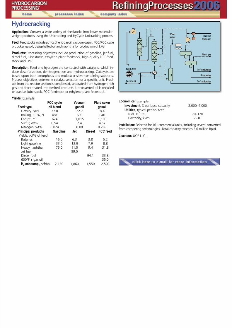
7/18/2019 Refining Processes Handbook 2006
http://slidepdf.com/reader/full/refining-processes-handbook-2006 114/222
HydrocrackingApplication: Convert a wide variety of feedstocks into lower-molecular-weight products using the Unicracking and HyCycle Unicracking process.
Feed: Feedstocks include atmospheric gasoil, vacuum gasoil, FCC/RCC cycleoil, coker gasoil, deasphalted oil and naphtha for production of LPG.
Products: Processing objectives include production of gasoline, jet fuel,diesel fuel, lube stocks, ethylene-plant feedstock, high-quality FCC feed-stock and LPG.
Description: Feed and hydrogen are contacted with catalysts, which in-duce desulfurization, denitrogenation and hydrocracking. Catalysts arebased upon both amorphous and molecular-sieve containing supports.Process objectives determine catalyst selection for a specific unit. Prod-
uct from the reactor section is condensed, separated from hydrogen-richgas and fractionated into desired products. Unconverted oil is recycledor used as lube stock, FCC feedstock or ethylene-plant feedstock.
Yields: Example:
FCC cycle Vacuum Fluid coker
Feed type oil blend gasoil gasoilGravity, °API 27.8 22.7 8.4Boiling, 10%, °F 481 690 640End pt., °F 674 1,015 1,100
Sulfur, wt% 0.54 2.4 4.57Nitrogen, wt% 0.024 0.08 0.269
Principal products Gasoline Jet Diesel FCC feed Yields, vol% of feed
Butanes 16.0 6.3 3.8 5.2Light gasoline 33.0 12.9 7.9 8.8Heavy naphtha 75.0 11.0 9.4 31.8Jet fuel 89.0Diesel fuel 94.1 33.8
600°F + gas oil 35.0H2 consump., scf/bbl 2,150 1,860 1,550 2,500
Economics: Example:
Investment, $ per bpsd capacity 2,000–4,000
Utilities, typical per bbl feed:Fuel, 103 Btu 70–120Electricity, kWh 7–10
Installation: Selected for 161 commercial units, including several convertedfrom competing technologies. Total capacity exceeds 3.6 million bpsd.
Licensor: UOP LLC.
�
�
Hydrocracking

7/18/2019 Refining Processes Handbook 2006
http://slidepdf.com/reader/full/refining-processes-handbook-2006 115/222
HydrocrackingApplication: Convert naphthas, AGO, VGO, DAO, cracked oils from FCCunits, delayed cokers and visbreakers, and intermediate products fromresidue hydroprocessing units using the Chevron Lummus Global ISO-
CRACKING Process.
Products: Lighter, high-quality, more valuable products: LPG, gasoline,catalytic reformer feed, jet fuel, kerosene, diesel and feeds for FCC, eth-ylene cracker or lube oil units.
Description: A broad range of both amorphous/zeolite and zeoliticcatalysts, including noble-metal zeolitic catalysts, are used to tailor theISOCRACKING Process exactly to the refiner’s objectives. In general,the process involves a staged reactor system with an initial stage of
hydrotreating and partially hydrocracking the feed, and a subsequentstage continuing the conversion or product upgrade process in a morefavorable environment.
Feeds can be introduced in between stages using Chevron LummusGlobal patented split-feed injection technology, or effluent flow paths canbe arranged to best utilize hydrogen and minimize quench-gas requirementsusing proprietary SSRS (single-stage reaction sequenced) technology.
Most modern large-capacity flow schemes involving heavy sour gasoils require two reactors (1, 4) and one high-pressure separation system(2) with an optional recycle gas scrubber (5) and one recycle-gas com-
pressor (8). The low-pressure separators (3), product stripper (6) andfractionator (7) provide the flexibility to fractionate products either inbetween reaction stages or at the tail-end, depending on desired prod-uct slate and selectivity requirements.
Single-stage options are used in once-through mode typically formild hydrocracking or when a significant quantity of unconverted oil isrequired for FCC, lubes, or ethylene units. The single-stage recycle op-tion is used for lower capacity units when economical. The reactors usepatented internals technology called ISOMIX for near-flawless mixingand redistribution.
Yields: Typical from various feeds:
Feed VGO VGO VGO VGOGravity, API 24.1 24.1 24.1 21.3TBP range, °F 700–1,100 700–1,100 700–1,100 700–1,100Nitrogen, wppm 2,500 2,500 2,500 900Sulfur, wt % 1.9 1.9 1.9 2.5Mode Max. Diesel Max. Jet Max. Mid- Max. Mid- Distillate Distillate
+ Lubes
Yields, vol % Naphtha 22.8 30.8 14.0 18 Jet/kerosine – 79.7 22.0 50 Diesel 85.5 – 73.0 35 UCO – – – 10
�
�
Continued
Feed VGO VGO VGO VGO
Product quality
Hydrocracking, continued

7/18/2019 Refining Processes Handbook 2006
http://slidepdf.com/reader/full/refining-processes-handbook-2006 116/222
Kerosine smoke, mm 29–32 29–32 29–32 Diesel cetane number 58–64 58–64 58–64 UCO BMCI 6–8 UCO Waxy V.I. 143–145 UCO Dewaxed V.I. 131–133
Economics: ISBL total installed cost of 35,000-BPSD unit at 100% con-version to middle distillates using Middle Eastern VGO feed (USGC, mid-2006 basis): $150 million.
Process fuel (absorbed), MMBtu/hr 180Electricity, MW 10CW, gpm 2,500Steam (export at 150 psig), M lb/hr 22
Installation: More than 60 units worldwide with over one million-bpsd
total capacity.
Licensor: Chevron Lummus Global LLC.
Hydrocracking—residue

7/18/2019 Refining Processes Handbook 2006
http://slidepdf.com/reader/full/refining-processes-handbook-2006 117/222
Hydrocracking—residueApplication: H-OilRC is an ebullated-bed process for hydrocracking at-mospheric or vacuum residue. It is the ideal solution for feedstocks hav-ing high metal, CCR and asphaltene contents. The process can have two
different objectives: at high conversion, to produce stable products; or,at moderate conversion, to produce a synthetic crude oil.
Description: The flow diagram illustrates a typical H-OilRC unit that in-cludes oil and hydrogen fired heaters, an optional inter stage separa-tor, an internal recycle cup providing feed to the ebullating pump, highpressure separators, recycle gas scrubber and product separation andfractionation (not required for synthetic crude oil production).
Catalyst is replaced periodically in the reactor, without shutdown.Different catalysts are available as a function of the feedstock and
the required objectives. An H-OilRC unit can operate for three-year runlengths at constant catalyst activity with conversion in the 50 – 80%range and hydrodesulfurization as high as 85%.
Operating conditions:Temperature, °F 770– 820Hydrogen partial pressure, psi 1,600 –1,950LHSV, hr –1 0.25– 0.6Conversion, wt% 50 – 80
Examples: Ural VR feed: a 540°C+ cut from Ural crude is processed at66% conversion to obtain a stable fuel oil containing less than 1%wtsulfur, 25% diesel and 30% VGO. The diesel cut is further hydrotreated
to meet ULSD specifications using an integrated Prime-D unit. Arab Me-
dium VR feed: a vacuum residue from a blend 70% Arab Light-30%Arab Heavy containing 5.5wt% sulfur is processed at above 75% con-version to obtain a stable fuel oil with 2wt% sulfur.
Economics: Basis 2005 US Gulf Coast
Investment in $ per bpsd 4,500 – 6,500
Utilities, per bbl of feedFuel, 103 Btu 70Power, kWh 11
Catalyst makeup, lb 0.2– 0.8
Installation: There are seven H-OilRC units in operation with a total capac-ity of 300,000 bpsd. Two additional references for H-OilDC, the ebullatedbed technology for VGO and DAO, add another 139,900 bpsd.
Licensor: Axens.
�
�
Hydrocracking

7/18/2019 Refining Processes Handbook 2006
http://slidepdf.com/reader/full/refining-processes-handbook-2006 118/222
HydrocrackingApplication: Desulfurization, demetalization, CCR reduction and hydro-cracking of atmospheric and vacuum resids using the LC-FINING Pro-cess.
Products: Full range of high-quality distillates. Residual products canbe used as fuel oil, synthetic crude or feedstock for a resid FCC, coker,visbreaker or solvent deasphalter.
Description: Fresh hydrocarbon liquid feed is mixed with hydrogen andreacted within an expanded catalyst bed (1) maintained in turbulence byliquid upflow to achieve efficient isothermal operation. Product quality ismaintained constant and at a high level by intermittent catalyst additionand withdrawal. Reactor products flow to a high-pressure separator (2),
low-pressure separator (3) and product fractionator (4). Recycle hydro-gen is separated (5) and purified (6).Process features include onstream catalyst addition and withdrawal.
Recovering and purifying the recycled H2 at low pressure rather than at highpressure can reduce capital cost and allows design at lower gas rates.
Operating conditions: Reactor temperature, °F 725 – 840Reactor pressure, psig 1,400 – 3,500H2 partial pressure, psig 1,000 – 2,700
LSHV 0.1 to 0.6Conversion, % 40 – 97+Desulfurization, % 60 – 90Demetalization, % 50 – 98CCR reduction, % 35 – 80
Yields: For Arabian heavy/Arabian light blends:
Atm. resid Vac. resid
Feed Gravity, °API 12.40 4.73 4.73 4.73Sulfur, wt % 3.90 4.97 4.97 4.97
Ni / V, ppmw 18 /65 39 /142 39 /142 39 /142Conversion, vol% 45 60 75 95 (1,022°F+)
Products, vol% C4 1.11 2.35 3.57 5.53C5–350°F 6.89 12.60 18.25 23.86350 –700°F (650°F) (15.24) 30.62 42.65 64.81700 (650°F) –1,022°F (55.27) 21.46 19.32 11.921,022°F+ 25.33 40.00 25.00 5.0
C5+, °API / wt% S 23.70 / 0.54 22.5 / 0.71 26.6 / 0.66 33.3 / 0.33
�
�
Continued
Economics:
Investment, estimated (US Gulf Coast, 2006)Si e bpsd fresh feed 92 000 49 000
Hydrocracking, continued

7/18/2019 Refining Processes Handbook 2006
http://slidepdf.com/reader/full/refining-processes-handbook-2006 119/222
Size, bpsd fresh feed 92,000 49,000$/bpsd typical fresh feed 3,000 5,000 5,800 7,200
Utilities, per bbl fresh feedFuel fired, 103 Btu 56.1 62.8 69.8 88.6Electricity, kWh 8.4 13.9 16.5 22.9
Steam (export), lb 35.5 69.2 97.0 97.7Water, cooling, gal. 64.2 163 164 248
Installation: Six LC-FINING units are in operation, and two LC-FININGUnits are in engineering.
Licensor: Chevron Lummus Global LLC.
Hydrodearomatization

7/18/2019 Refining Processes Handbook 2006
http://slidepdf.com/reader/full/refining-processes-handbook-2006 120/222
HydrodearomatizationApplication: Topsøe’s two-stage hydrodesulfurization hydrodearomati-zation (HDS/HDA) process is designed to produce low-aromatics distil-late products. This process enables refiners to meet the new, stringent
standards for environmentally friendly fuels.
Products: Ultra-low sulfur, ultra-low nitrogen, low-aromatics diesel, ker-osine and solvents (ultra-low aromatics).
Description: The process consists of four sections: initial hydrotreating,intermediate stripping, final hydrotreating and product stripping. Theinitial hydrotreating step, or the “first stage” of the two-stage reactionprocess, is similar to conventional Topsøe hydrotreating, using a Topsøehigh-activity base metal catalyst such as TK-575 BRIM to perform deep
desulfurization and deep denitrification of the distillate feed. Liquid ef-fluent from this first stage is sent to an intermediate stripping section, inwhich H2S and ammonia are removed using steam or recycle hydrogen.Stripped distillate is sent to the final hydrotreating reactor, or the “secondstage.” In this reactor, distillate feed undergoes saturation of aromaticsusing a Topsøe noble metal catalyst, either TK-907/TK-911 or TK-915, ahigh-activity dearomatization catalyst. Finally, the desulfurized, dearoma-tized distillate product is steam stripped in the product stripping columnto remove H2S, dissolved gases and a small amount of naphtha formed.
Like the conventional Topsøe hydrotreating process, the HDS/HDA
process uses Topsøe’s graded bed loading and high-efficiency patentedreactor internals to provide optimum reactor performance and catalystuse leading to the longest possible catalyst cycle lengths. Topsøe’s highefficiency internals have a low sensitivity to unlevelness and are designedto ensure the most effective mixing of liquid and vapor streams and max-imum utilization of catalyst. These internals are effective at high liquidloadings, thereby enabling high turndown ratios. Topsøe’s graded-bedtechnology and the use of shape-optimized inert topping and catalystsminimize the build-up of pressure drop, thereby enabling longer catalystcycle length.
Operating conditions: Typical operating pressures range from 20 to 60barg (300 to 900 psig), and typical operating temperatures range from320°C to 400°C (600°F to 750°F) in the first stage reactor, and from260°C to 330°C (500°F to 625°F) in the second stage reactor. An ex-
ample of the Topsøe HDS/HDA treatment of a heavy straight-run gas oilfeed is shown below:
Feed ProductSpecific gravity 0.86 0.83Sulfur, ppmw 3,000 1Nitrogen, ppmw 400 <1Total aromatics, wt% 30 <10Cetane index, D-976 49 57
�
�
�
Continued
References: Cooper, Hannerup and Søgaard-Andersen, “Reduction ofaromatics in diesel,” Oil and Gas, September 1994.
de la Fuente E P Christensen and M Johansen “Options for meet
Hydrodearomatization, continued

7/18/2019 Refining Processes Handbook 2006
http://slidepdf.com/reader/full/refining-processes-handbook-2006 121/222
de la Fuente, E., P. Christensen, and M. Johansen, Options for meet-ing EU year 2005 fuel specifications,” 4th ERTC, Paris, November 1999.
Installation: A total of seven units.
Licensor: Haldor Topsøe A/S.
Hydrofinishing

7/18/2019 Refining Processes Handbook 2006
http://slidepdf.com/reader/full/refining-processes-handbook-2006 122/222
HydrofinishingApplication: Deeply saturate single- and multiple-ring aromatics in base-oil feedstocks. The product will have very low-aromatics content, veryhigh-oxidation stability and high thermal stability.
Description: ISOFINISHING catalysts hydrogenate aromatics at relative-ly low reaction temperatures. They are especially effective in completepolyaromatics saturation—a reaction that is normally equilibrium limited.Typical feedstocks are the effluent from a dewaxing reactor, effluent fromhydrated feeds or solvent-dewaxed feedstocks. The products are highlystabilized base-oil, technical-grade white oil or food-grade white oil.
As shown in the simplified flow diagram, feedstocks are mixed withrecycle hydrogen and fresh makeup hydrogen, heated and charged to areactor containing ISOFINISHING Catalyst (1). Effluent from the finishing
reactor is flashed in high-pressure and low-pressure separators (2, 3).A very small amount of light products are recovered in a fractionationsystem (4).
Yields: For a typical feedstock, such as dewaxing reactor effluent, theyield can be >99%. The chemical-hydrogen consumption is usually verylow, less than ~10 Nm3 /m3 oil.
Economics:
Investment: For a stand-alone ISOFINISHING Unit, the ISBL capital isabout 3,000 –5,000 $/bpsd, depending on the pressurelevel and size.
Utilities: Typical per bbl feed: Power, kW 2.6 Fuel, kcal 3.4 x 10³
Installation: Twenty-five units are in various stages of operation, con-struction or design.
Reference: NPRA Annual Meeting, March 2004, San Antonio, PaperAM-04-68.
Licensor: Chevron Lummus Global LLC.
�
�
Hydrofinishing/hydrotreating

7/18/2019 Refining Processes Handbook 2006
http://slidepdf.com/reader/full/refining-processes-handbook-2006 123/222
Hydrofinishing/hydrotreatingApplication: Process to produce finished lube-base oils and special oils.
Feeds: Dewaxed solvent or hydrogen-refined lube stocks or raw vacuumdistillates for lubricating oils ranging from spindle oil to machine oil andbright stock.
Products: Finished lube oils (base grades or intermediate lube oils) andspecial oils with specified color, thermal and oxidation stability.
Description: Feedstock is fed together with make-up and recycle hydro-gen over a fixed-bed catalyst at moderate temperature and pressure.The treated oil is separated from unreacted hydrogen, which is recycled.Very high yields product are obtained.
For lube-oil hydrofinishing, the catalytic hydrogenation process is
operated at medium hydrogen pressure, moderate temperature and lowhydrogen consumption. The catalyst is easily regenerated with steamand air.
Operating pressures for hydrogen-finishing processes range from25 to 80 bar. The higher-pressure range enables greater flexibility withregard to base-stock source and product qualities. Oil color and thermalstability depend on treating severity. Hydrogen consumption dependson the feed stock and desired product quality.
Utility requirements (typical, Middle East Crude), units per m3 of feed:
Electricity, kWh 15 Steam, MP, kg 25 Steam, LP, kg 45 Fuel oil, kg 3 Water, cooling, m3 10
Installation: Numerous installations using the Uhde (Edeleanu) propri-etary technology are in operation worldwide. The most recent referenceis a complete lube-oil production facility licensed to the state of Turk-menistan.
Licensor: Uhde GmbH.
�
Hydrogen

7/18/2019 Refining Processes Handbook 2006
http://slidepdf.com/reader/full/refining-processes-handbook-2006 124/222
HydrogenApplication: Production of hydrogen ( H2 ) from hydrocarbon (HC) feed-stocks, by steam reforming.
Feedstocks: Ranging from natural gas to heavy naphtha as well as po-tential refinery offgases. Many recent refinery hydrogen plants havemultiple feedstock flexibility, either in terms of back-up or alternativeor mixed feed. Automatic feedstock change-over has also successfullybeen applied by TECHNIP in several modern plants with multiple feed-stock flexibility.
Description: The generic flowsheet consists of feed pretreatment, pre-reforming (optional), steam-HC reforming, shift conversion and hydro-gen purification by pressure swing adsorption (PSA). However, it is often
tailored to satisfy specific requirements.Feed pretreatment normally involves removal of sulfur, chlorine andother catalyst poisons after preheating to 350°C to 400°C.
The treated feed gas mixed with process steam is reformed in a firedreformer (with adiadatic pre-reformer upstream, if used) after neces-sary superheating. The net reforming reactions are strongly endother-mic. Heat is supplied by combusting PSA purge gas, supplemented bymakeup fuel in multiple burners in a top-fired furnace.
Reforming severity is optimized for each specific case. Waste heatfrom reformed gas is recovered through steam generation before the
water-gas shift conversion. Most of the carbon monoxide is further con-verted to hydrogen. Process condensate resulting from heat recoveryand cooling is separated and generally reused in the steam system afternecessary treatment. The entire steam generation is usually on naturalcirculation, which adds to higher reliability. The gas flows to the PSA unitthat provides high-purity hydrogen product (up to < 1ppm CO) at nearinlet pressures.
Typical specific energy consumption based on feed + fuel – exportsteam ranges between 3.0 and 3.5 Gcal / KNm3 ( 330 – 370 Btu / scf ) LHV,depending upon feedstock, plant capacity, optimization criteria andsteam-export requirements. Recent advances include integration of hy-
drogen recovery and generation, and recuperative (post-)reforming alsofor capacity retrofits.
Installations: TECHNIP has been involved in over 240 hydrogen plants
worldwide, covering a wide range of capacities. Most installations arefor refinery application with basic features for high reliability and opti-mized cost.
Licensor: Technip.
�
�
Hydrogen

7/18/2019 Refining Processes Handbook 2006
http://slidepdf.com/reader/full/refining-processes-handbook-2006 125/222
HydrogenApplication: Production of hydrogen for refinery applications (e.g.,hydrotreating and hydrocracking) as well as for petrochemical and otherindustrial uses.
Feed: Natural gas, refinery offgases, LPG, naphtha or mixtures thereof.
Product: High-purity hydrogen (typically >99.9%), CO, CO2, HP steamand/or electricity may be produced as separate creditable byproduct.
Description: The plant generally comprises four process units. The feedis desulfurized (1), mixed with steam and converted to synthesis gas in asteam reformer (2) over a nickel-containing catalyst at 20 – 40 bar pres-sure and outlet temperatures of 800 – 900°C.
The Uhde steam reformer features a well-proven, top-fired design
with tubes made of centrifugally cast alloy steel and a unique propri-etary “cold” outlet manifold system for enhanced reliability. A furtherspecialty is Uhde’s bi-sectional steam system for the environment-friend-ly full recovery of process condensate and production of contaminant-free high-pressure export steam (3) with a proven process gas coolerdesign. The Uhde steam reformer concept also includes a modularizedshop-tested convection bank to maximize plant quality and minimizeconstruction risks.
The final process units are the adiabatic carbon monoxide (CO) shift(4) and the pressure swing adsorption unit (5) to obtain high-purity hy-drogen. Process options include feed evaporation, adiabatic feed pre-reforming and/or HT/LT shift to process, e.g., heavier feeds and/or opti-mize feed/fuel consumption and steam production.
Uhde’s design allows combining maximized process heat recovery andoptimized energy efficiency with operational safety and reliability. Uhdeusually offers tailor-made designs based on either its own or the custom-er’s design standards. The hydrogen plant is often fully integrated into therefinery, particularly with respect to steam production and the usage ofrefinery waste gases. Furthermore, Uhde has wide experience in the con-
struction of highly reliable large-scale reformers for hydrogen capacities ofup to 220,000 Nm3 / h (197 MMscfd) in single-train configurations.
Economics: Depending on the individual plant concept, the typical con-sumption figure for natural gas based plants (feed + fuel – steam) maybe lower than 3.13 Gcal /1,000 Nm3 (333 MMBtu/ MMscf) or 3.09 (329)with prereforming.
Installation: Uhde has recently been awarded several designs for hydro-gen plants. These include a 150,000 Nm³/ h (134 MMscfd) plant for Shellin Canada, a 91,000 Nm³/ h (81 MMscfd) plant for Bayernoil in Germanyand a 100,000 Nm³/ h (89 MMscfd) plant for SINCOR C.A. in Venezuela.In addition, Uhde is cooperating with Caloric, Germany, in executing acontract from Shell for a 10,000 Nm3 /h (9 MMscfd) plant in Argentina.This marks the first success in the partnership of Uhde and Caloric inthe field of smaller-sized hydrogen plants. During 2006, Uhde will alsostartup Europe’s largest hydrogen plant for Neste Oil Corp. of Finland,formerly Fortum Oil, with a capacity of 155,000 Nm³/ h (139 MMscfd).
�
�
Continued
References: Ruthardt, K., K. R. Radtke and J. Larsen, “Hydrogen trends,”Hydrocarbon Engineering, November 2005, pp. 41– 45.
Michel M “Design and Engineering Experience with Large-Scale
Hydrogen, continued

7/18/2019 Refining Processes Handbook 2006
http://slidepdf.com/reader/full/refining-processes-handbook-2006 126/222
Michel, M., Design and Engineering Experience with Large ScaleHydrogen Plants,” Oil Gas European Magazine, Vol. 30 (2004) No. 2 in:Erdöl Erdgas Kohle Vol. 120 (2004) No. 6, pp. OG 85– 88.
Licensor: Uhde GmbH.
Hydrogenation

7/18/2019 Refining Processes Handbook 2006
http://slidepdf.com/reader/full/refining-processes-handbook-2006 127/222
HydrogenationApplication: The CDHydro process is used to selectively hydrogenate diole-fins in the top section of a hydrocarbon distillation column. Additional ap-plications—including mercaptan removal, hydroisomerization and hydro-
genation of olefins and aromatics are also available.
Description: The patented CDHydro process combines fractionationwith hydrogenation. Proprietary devices containing catalyst are installedin the fractionation column’s top section (1). Hydrogen is introducedbeneath the catalyst zone. Fractionation carries light components intothe catalyst zone where the reaction with hydrogen occurs. Fraction-ation also sends heavy materials to the bottom. This prevents foulantsand heavy catalyst poisons in the feed from contacting the catalyst. Inaddition, clean hydrogenated reflux continuously washes the catalystzone. These factors combine to give a long catalyst life. Additionally,mercaptans can react with diolefins to make heavy, thermally-stable sul-fides. The sulfides are fractionated to the bottoms product. This caneliminate the need for a separate mercaptan removal step. The distillateproduct is ideal feedstock for alkylation or etherification processes.
The heat of reaction evaporates liquid, and the resulting vapor iscondensed in the overhead condenser (2) to provide additional reflux.The natural temperature profile in the fractionation column results in avirtually isothermal catalyst bed rather than the temperature increase
typical of conventional reactors.The CDHydro process can operate at much lower pressure thanconventional processes. Pressures for the CDHydro process are typicallyset by the fractionation requirements. Additionally, the elimination of aseparate hydrogenation reactor and hydrogen stripper offers significantcapital cost reduction relative to conventional technologies.
Feeding the CDHydro process with reformate and light-straight runfor benzene saturation provides the refiner with increased flexibility toproduce low-benzene gasoline. Isomerization of the resulting C5 / C6
overhead stream provides higher octane and yield due to reduced ben-
zene and C7+ content compared to typical isomerization feedstocks.
Economics: Fixed-bed hydrogenation requires a distillation column fol-lowed by a fixed-bed hydrogenation unit. The CDHydro process elimi-nates the fixed-bed unit by incorporating catalyst in the column. Whena new distillation column is used, capital cost of the column is only 5%
to 20% more than for a standard column depending on the CDHydroapplication. Elimination of the fixed-bed reactor and stripper can reducecapital cost by as much as 50%.
Installation: Forty-five CDHydro units are in commercial operation forC4, C5, C6 and benzene hydrogenation applications. Nineteen unitshave been in operation for more than five years and total commer-cial operating time now exceeds 100 years for CDHydro technologies.Twelve additional units are currently in engineering / construction.
Licensor: CDTECH.
�
�
�
Hydrogen—HTCR and HTCR twin

7/18/2019 Refining Processes Handbook 2006
http://slidepdf.com/reader/full/refining-processes-handbook-2006 128/222
y gplantsApplication: Produce hydrogen from hydrocarbon feedstocks such as:natural gas, LPG, naphtha, refinery offgases, etc., using the Haldor Top-søe Convective Reformer (HTCR). Plant capacities range from approxi-mately 5,000 Nm3 / h to 25,000+ Nm3 / h (5 MM scfd to 25+ MMscfd) andhydrogen purity from about 99.5 – 99.999+%. This is achieved withoutany steam export.
Description: The HTCR-based hydrogen plant can be tailor-made to suitthe customer’s needs with respect to feedstock flexibility. A typical plantcomprises feedstock desulfurization, pre-reforming, HTCR reforming,shift reaction and pressure swing adsorption (PSA) purification to obtainproduct-grade hydrogen. PSA offgases are used as fuel in the HTCR. Ex-cess heat in the plant is efficiently used for process heating and processsteam generation.
A unique feature of the HTCR is the high thermal efficiency. Productgas and flue gas are cooled by providing heat to the reforming reac-tion to about 600°C (1,100°F). The high thermal efficiency is utilizedto design energy-efficient hydrogen plants without the need for steamexport. In larger plants, the reforming section consists of two HTCR re-formers operating in parallel.
Economics: HTCR-based hydrogen plants provide the customer witha low-investment cost and low operating expenses for hydrogen pro-duction. The plant is supplied as a skid-mounted unit providing a shortinstallation time. These plants provide high operating flexibility, reliabil-ity and safety. Fully automated operation, startup and shutdown allowminimum operator attendance. A net energy efficiency of about 3.4Gcal / 1,000 Nm3 hydrogen (361 MMBtu /scf H2) is achieved dependingon size and feedstock.
Installations: Twenty-eight licensed units.
Licensor: Haldor Topsøe A/S.
�
Hydrogen—HTER-p

7/18/2019 Refining Processes Handbook 2006
http://slidepdf.com/reader/full/refining-processes-handbook-2006 129/222
y g pApplication: Topsøe’s proprietary and patented HTER-p (Haldor Top-søe Exchange Reformer—parallel installation) technology is a revampoption for production increase in a steam-reforming-based hydrogen
plant. The technology allows hydrogen capacity increases of more than25%. This option is especially advantageous because the significant ca-pacity expansion is possible with minimal impact on the existing tubularreformer, which usually is the plant bottleneck.
Description: The HTER-p is installed in parallel with the tubular steammethane reformer (SMR) and fed independently with desulfurizedfeed taken upstream the reformer section. This enables individual ad-
justment of feedrate and steam- and process steam-to-carbon ratio toobtain the desired conversion. The hydrocarbon feed is reformed over
a catalyst bed installed in the HTER-p. Process effluent from the SMRis transferred to the HTER-p and mixed internally with the product gasfrom the HTER-p catalyst. The process gas supplies the required heatfor the reforming reaction in the tubes of the HTER-p. Thus, no addi-tional firing is required for the reforming reactions in the HTER-p.
Economics: An HTER-p offers a compact and cost-effective hydrogencapacity expansion. The investment cost is as low as 60% of that for anew hydrogen plant. Energy consumption increases only slightly. For a25% capacity increase, the net energy consumption is 3.13 Gcal / 1,000
Nm3
H2 (333 MM Btu / scf H2 ).
References: Dybkjær, I., and S. W. Madsen, “Novel Revamp Solutionsfor Increased Hydrogen Demands,” Eighth European Refining Technol-ogy Conference, November 17–19, 2003, London, UK
Licensor: Haldor Topsøe A/S.
�
�
Hydrogen—Methanol-to-Shift

7/18/2019 Refining Processes Handbook 2006
http://slidepdf.com/reader/full/refining-processes-handbook-2006 130/222
y gApplication: Topsøe’s proprietary Methanol-to-Shift technology is a re-vamp option for hydrogen production increase for a reforming-basedhydrogen plant. This technology can raise hydrogen production ca-
pacity by more than 25%. The capacity expansion is flexible and canbe changed in very short time; the technology is suitable for capacitypeak shaving and offers the refiner higher feedstock and product slateflexibility.
Description: Additional hydrogen is produced by reforming of methanolover Topsøe’s novel dual-function catalyst—LK-510. When installed in theexisting CO shift converter and fed simultaneously with methanol and re-formed gas, the LK-510 catalyst promotes both the conversion of CO withsteam to H2 and CO2 and the reforming of methanol to H2 and CO2.
Methanol from a day tank is pumped to a steam-heated evaporatorand fed as vapor to the existing CO shift converter, now loaded withthe LK-510 catalyst. In most cases, it will be necessary to revamp thePSA unit for the additional capacity and to check the equipment down-stream of the CO shift converter and modify as required.
Economics: The Methanol-to-Shift revamp technology is a low-invest-ment option for hydrogen capacity increase and is rapid to install. Thetotal investment cost is less than 40% of that of a new hydrogen plant.Methanol consumption is approximately 0.54 kg / Nm3 hydrogen (0.03
lb/scf H2).
References: Dybkjær, I., and S. W. Madsen, “Novel Revamp Solutionsfor Increased Hydrogen Demands,” Eighth European Refining Technol-ogy Conference, November 17–19, 2003, London, UK.
Licensor: Haldor Topsøe A/S.
�
Hydrogen—recovery

7/18/2019 Refining Processes Handbook 2006
http://slidepdf.com/reader/full/refining-processes-handbook-2006 131/222
y g yApplication: To recover and purify hydrogen or to reject hydrogen fromrefinery, petrochemical or gas processing streams using a PRISM mem-brane. Refinery streams include hydrotreating or hydrocracking purge,
catalytic reformer offgas, fluid catalytic cracker offgas or fuel gas. Pet-rochemical process streams include ammonia synthesis purge, methanolsynthesis purge or ethylene offgas. Synthesis gas includes those gener-ated from steam reforming or partial oxidation.
Product: Typical hydrogen (H2) product purity is 90 – 98% and, in somecases, 99.9%. Product purity is dependent upon feed purity, availabledifferential partial pressure and desired H2 recovery level. Typical H2 re-covery is 80–95% or more.
The hydrocarbon-rich nonpermeate product is returned at nearly
the same pressure as the feed gas for use as fuel gas, or in the case ofsynthesis gas applications, as a carbon monoxide (CO) enriched feed tooxo-alcohol, organic acid, or Fisher-Tropsch synthesis.
Description: Typical PRISM membrane systems consist of a pretreatment(1) section to remove entrained liquids and preheat feed before gas en-ters the membrane separators (2). Various membrane separator con-figurations are possible to optimize purity and recovery, and operatingand capital costs such as adding a second stage membrane separator(3). Pretreatment options include water scrubbing to recover ammonia
from ammonia synthesis purge stream.Membrane separators are compact bundles of hollow fibers contained in
a coded pressure vessel. The pressurized feed enters the vessel and flows onthe outside of the fibers (shell side). Hydrogen selectively permeates throughthe membrane to the inside of the hollow fibers (tube side), which is at lowerpressure. PRISM membrane separators’ key benefits include resistance to wa-ter exposure, particulates and low feed to nonpermeate pressure drop.
Membrane systems consist of a pre-assembled skid unit with pres-sure vessels, interconnecting piping, and instrumentation and are fac-tory tested for ease of installation and commissioning.
Economics: Economic benefits are derived from high-product recoveriesand purities, from high reliability and low capital cost. Additional ben-efits include relative ease of operation with minimal maintenance. Also,systems are expandable and adaptable to changing requirements.
Installations: Over 270 PRISM H2 membrane systems have been com-missioned or are in design. These systems include over 54 systems in re-
finery applications, 124 in ammonia synthesis purge and 30 in synthesisgas applications.
Licensor: Air Products and Chemicals, Inc.
�
�
Hydrogen — steam reforming

7/18/2019 Refining Processes Handbook 2006
http://slidepdf.com/reader/full/refining-processes-handbook-2006 132/222
Application: Production of hydrogen for refinery hydrotreating and hydro-cracking or other refinery, petrochemical and other uses.
Feedstock: Light hydrocarbons such as natural gas, refinery fuel gas, LPG/bu-
tane mixed pentanes and light naphtha.
Product: High-purity hydrogen (99.9+%) at any required pressure.
Description: The feed is heated in the feed preheater and passed throughthe hydrotreater (1). The hydrotreater converts sulfur compounds to H2S andsaturates any unsaturated hydrocarbons in the feed. The gas is then sent tothe desulfurizers (2). These adsorb the H2S from the gas.
The desulfurized feed gas is mixed with steam and superheated in thefeed preheat coil. The feed mixture then passes through catalyst-filled tubes in
the reformer (3). In the presence of nickel catalyst, the feed reacts with steamto produce hydrogen and carbon oxides. Heat for the endothermic reform-ing reaction is provided by carefully controlled external firing in the reformer.Combustion air preheat is used, if applicable to limit export steam.
Gas leaving the reformer is cooled by the process steam generator (4). Gasis then fed to the shift converter (5), which contains a bed of copper-promotediron-chromium catalyst. This converts CO and water vapor to additional H2 and CO2. Shift converter effluent gas is cooled, condensate is separated andthe gas is sent to a PSA hydrogen purification system (6).
The PSA system operates on a repeated cycle having two basic steps: ad-sorption and regeneration. PSA offgas is sent to the reformer, where it providesmost of the fuel requirement. Hydrogen from the PSA unit is sent off plot. Asmall hydrogen stream is recycled to the feed of the plant for hydrotreating.
The thermal efficiency of the plant is optimized by recovery of heatfrom the reformer flue gas stream and from the reformer effluent processgas stream. This energy is utilized to preheat reformer feed gas and generatesteam for reforming and export. The process design is customized for eachapplication depending on project economics and export steam demand.
Economics: Typical utilities per Mscf of hydrogen production based on anatural gas feedstock and maximum export steam:
Feed and fuel, MM Btu LHV 0.44Export steam, lb 75Boiler feedwater, lb 115Power, kW 0.5Water, cooling, gal 10
Installations: Over 175 plants worldwide — ranging in size from less than1 MMscfd to over 120 MMscfd capacities. Plant designs for capacitiesfrom 1 to 200 MMscfd.
Supplier: CB&I Howe Baker.
�
�
Hydrogen—steam reforming

7/18/2019 Refining Processes Handbook 2006
http://slidepdf.com/reader/full/refining-processes-handbook-2006 133/222
Application: Manufacture hydrogen for hydrotreating, hydrocracking orother refinery or chemical use.
Feedstock: Light saturated hydrocarbons: refinery gas or natural gas,LPG or light naphtha.
Products: Typical purity 99.99%; pressure 300 psig, with steam or CO2
as byproducts.
Description: Hydrogen is produced by steam reforming of hydrocarbonswith purification by pressure swing adsorption (PSA). Feed is heated (1)and then hydrogenated (2) over a cobalt-molybdenum catalyst bed fol-lowed by purification (3) with zinc oxide to remove sulfur. The purifiedfeed is mixed with steam and preheated further, then reformed over
nickel catalyst in the tubes of the reforming furnace (1).Foster Wheeler’s Terrace Wall reformer combines high efficiency with
ease of operation and reliability. Depending on size or site requirements,Foster Wheeler can also provide a down-fired furnace. Combustion airpreheat can be used to reduce fuel consumption and steam export.
Pre-reforming can be used upstream of the reformer if a mixtureof naphtha and light feeds will be used, or if steam export must beminimized. The syngas from the reformer is cooled by generating steam,then reacted in the shift converter (4) where CO reacts with steam toform additional H
2 and CO
2.
In the PSA section (5), impurities are removed by solid adsorbent,and the adsorbent beds are regenerated by depressurizing. Purge gasfrom the PSA section, containing CO2, CH4, CO and some H2, is used asfuel in the reforming furnace. Heat recovery from reformer flue gas maybe via combustion air preheat or additional steam generation. Variationsinclude a scrubbing system to recover CO2.
Economics:Investment: 10 –100 MMscfd, First Q 2005, USGC $10 – 60 millionUtilities, 50 MMscfd plant:
Air Steampreheat generation
Natural gas, feed + fuel, MMBtu/hr 780 885Export steam at 600 psig/700ºF, lb/hr 35,000 130,000Boiler feedwater, lb/hr 70,000 170,000
Electricity, kW 670 170 Water, cooling, 18ºF rise, gpm 350 350
Installations: Over 100 plants, ranging from less than 1 MMscfd to 95MMscfd in a single train, with numerous multi-train installations.
Reference: Handbook of Petroleum Refining Processes, Third Ed., Mc-Graw-Hill, 2003, pp 6.3–6.33.
Licensor: Foster Wheeler.
�
�
Hydrogen—steam methanef i (SMR)

7/18/2019 Refining Processes Handbook 2006
http://slidepdf.com/reader/full/refining-processes-handbook-2006 134/222
reforming (SMR)Application: Production of hydrogen from hydrocarbon feedstocks suchas: natural gas, LPG, butane, naphtha, refinery offgases, etc., using the
Haldor Topsøe radiant-wall Steam Methane Reformer (SMR). Plant ca-pacities range from 5,000 Nm3 /h to more than 200,000 Nm3 /h hydro-gen (200+ MMscfd H2) and hydrogen purity of up to 99.999+%.
Description: The Haldor Topsøe SMR-based hydrogen plant is tailor-madeto suit the customer’s needs with respect to economics, feedstock flex-ibility and steam export. In a typical Topsøe SMR-based hydrogen plant,a mix of hydrocarbon feedstocks or a single feedstock stream is first de-sulfurized. Subsequently, process steam is added, and the mixture is fedto a prereformer. Further reforming is carried out in the Haldor Topsøeradiant wall SMR. The process gas is reacted in a medium-temperatureCO shift reactor and purified by pressure swing absorption (PSA) to ob-tain product-grade hydrogen. PSA offgases are used as fuel in the SMR.Excess heat in the plant is efficiently used for process heating and steamgeneration.
The Haldor Topsøe radiant wall SMR operates at high outlet temper-atures up to 950°C (1,740°F). The Topsøe reforming catalysts allow op-eration at low steam-to-carbon ratio. Advanced Steam Reforming usesboth high outlet temperature and low steam-to-carbon ratio, which are
necessary for high-energy efficiency and low hydrogen production cost.The Advanced Steam Reforming design is in operation in many indus-trial plants throughout the world.
Economics: The Advanced Steam Reforming conditions described canachieve a net energy efficiency as low as 2.96 Gcal /1,000 Nm3 hydrogenusing natural gas feed (315 MM Btu/scf H2).
Installations: More than 100 units.
References: Rostrup-Nielsen, J. R. and T. Rostrup-Nielsen, “Large scalehydrogen production,” CatTech, Vol. 6, no. 4, 2002.
Dybkjær, I., and S. W. Madsen, “Advanced reforming technologiesfor hydrogen production,” Hydrocarbon Engineering, December/Janu-
ary 1997/1998.Gøl, J.N., and I. Dybkjær, “Options for hydrogen production,” HTI
Quarterly : Summer 1995.
Licensor: Haldor Topsøe A/S.
�
�
�
Hydroprocessing, residue

7/18/2019 Refining Processes Handbook 2006
http://slidepdf.com/reader/full/refining-processes-handbook-2006 135/222
Application: Produces maximum distillates and low-sulfur fuel oil, orlow-sulfur LR-CCU feedstock, with very tight sulfur, vanadium and CCRspecifications, using moving bed “bunker” and fixed-bed technologies.
Bunker units are available as a retrofit option to existing fixed-bed resi-due HDS units.
Description: At limited feed metal contents, the process typically usesall fixed-bed reactors. With increasing feed metal content, one or moremoving-bed “bunker” reactors are added up-front of the fixed-bed re-actors to ensure a fixed-bed catalyst life of at least one year. A steadystate is developed by continuous catalyst addition and withdrawal: thecatalyst aging is fully compensated by catalyst replacement, at typically0.5 to 2 vol% of inventory per day.
An all bunker option, which eliminates the need for catalyst change-out,is also available. A hydrocracking reactor, which converts the synthetic vacu-um gasoil into distillates, can be efficiently integrated into the unit. A widerange of residue feeds, like atmospheric or vacuum residues and deasphaltedoils, can be processed using Shell residue hydroprocessing technologies.
Operating conditions:Reactor pressures: 100 – 200 bar 1,450 – 3,000 psiReactor temperatures: 370 – 420°C 700 – 790°F
Yields: Typical yields for an SR HYCON unit on Kuwait feed:
Feedstock SR (95% 520C+) with integrated HCU
Yields: [%wof] [%wof]Gases C1 – C4 3 5Naphtha C5 – 165°C 4 18Kero + gasoil 165 – 370°C 20 43VGO 370 – 580°C 41 4Residue 580°C+ 29 29H2 cons. 2 3
Economics: Investment costs for the various options depend strongly on
feed properties and process objectives of the residue hydroprocessing
unit. Investment costs for a typical new single string 5,000 tpsd SR-Hy-con unit will range from 200 to 300 MM US$; the higher figure includesan integrated hydrocracker.
Installation: There is one unit with both bunker reactors and fixed-bedreactors, operating on short residue (vacuum residue) at 4,300 tpd or27 Mbpsd capacity, and two all-fixed bed units of 7,700 and 7,000 tpd(48 and 44 Mbpsd resp.), the latter one in one single string. Commercialexperiences range from low-sulfur atmospheric residues to high-metal,high-sulfur vacuum residues with over 300-ppmw metals.
Reference: Scheffer, B., et al, “The Shell Residue Hydroconversion Pro-cess: Development and achievements,” The European Refining Technol-ogy Conference, London, November 1997.
Licensor: Shell Global Solutions International B.V.
� �
� �
�
�
Hydroprocessing, ULSD

7/18/2019 Refining Processes Handbook 2006
http://slidepdf.com/reader/full/refining-processes-handbook-2006 136/222
Application: A versatile family of ExxonMobil Research and EngineeringCo. (EMRE) process technologies and catalysts are used to meet all cur-rent and possible future premium diesel requirements.
ULSD HDS—Ultra-deep hydrodesulfurization process to produce distil-late products with sulfur levels below 10 wppm.
HDHC—Heavy-distillate mild-hydrocracking process for the reduction ofT90 and T95 boiling points, and high-level density reduction.
MAXSAT—High-activity aromatics saturation process for the selectivereduction of polyaromatics under low pressure and tempera-ture conditions.
CPI—Diesel cloud point improvement by selective normal paraffin hydro-cracking (MDDW) or by paraffin isomerization dewaxing (MIDW).
Description: EMRE units combine the technologies listed above inlow-cost integrated designs to achieve the necessary product uplift atminimum investment and operating cost. For ultra-low-sulfur-dieselhydrodesulfurization (ULSD HDS), a single-stage single-reactor processcan be designed. A small cetane improvement, together with the reduc-tion of polyaromatics to less than 11 wt.% or as low as 5 wt.%, canbe economically achieved with proper specification of catalyst, hydrogenpartial pressure, space velocity and the installation of high-performanceSpider Vortex internals.
The addition of heavy-diesel hydrocracking (HDHC) function to theHDS reactor can achieve T95 boiling point reduction together withhigher levels of density and aromatics reduction and greater cetaneimprovement.
When feedstock aromatics are very high, or very low aromatics inthe product are desired, a second-stage aromatics saturation (MAXSAT)system is specified to avoid very high design pressures required for asingle-step base-metal hydrotreating catalyst system. When the distil-late product must also meet stringent fluidity specifications, EMRE canoffer either paraffin isomerization dewaxing (MIDW) or selective normal
paraffin cracking-based dewaxing technologies (MDDW). These can be
closely integrated with ULSD HDS and other functions to achieve the fullupgrading requirements.
The EMRE ULSD technologies are equally amenable to revamp orgrassroots applications. EMRE has an alliance with Kellogg Brown &Root (KBR) to provide these technologies to refiners.
Economics:
Investment: (Basis: 20,000–35,000 bpsd, 1st quarter2004 US Gulf Coast)
New unit, $/bpsd 1,200–2,000
Installation: Nineteen distillate upgrading units have applied the EMREULSD technologies. Twelve of these applications are revamps.
Licensor: ExxonMobil Research and Engineering Co.
�
Hydrotreating

7/18/2019 Refining Processes Handbook 2006
http://slidepdf.com/reader/full/refining-processes-handbook-2006 137/222
Application: Hydroprocessing of middle distillates, including crackedmaterials (coker/visbreaker gas oils and LCO), using SynTechnologymaximizes distillate yield while producing ultra-low-sulfur diesel (ULSD)
with improved cetane and API gain, reduced aromatics, T95 reductionand cold-flow improvement through selective ring opening, saturationand/or isomerization. Various process configurations are available forrevamps and new unit design to stage investments to meet changingdiesel specifications.
Products: Maximum yield of improved quality distillate while minimizingfuel gas and naphtha. Diesel properties include less than 10-ppm sulfur,with aromatics content (total and/or PNA), cetane, density and T95 de-pendent on product objectives and feedstock.
Description: SynTechnology includes SynHDS for ultra-deep desulfuri-zation and SynShift / SynSat for cetane improvement, aromatics satura-tion and density / T95 reduction. SynFlow for cold flow improvementcan be added as required. The process combines ABB Lummus Glob-al’s cocurrent and/or patented countercurrent reactor technology withspecial SynCat catalysts from Criterion Catalyst Co. LP. It incorporatesdesign and operations experience from Shell Global Solutions to maxi-mize reactor performance by using advanced reactor internals.
A single-stage or integrated two-stage reactor system provides
various process configuration options and revamp opportunities. In atwo-stage reactor system, the feed, makeup and recycle gas are heatedand fed to a first-stage cocurrent reactor. Effluent from the first stageis stripped to remove impurities and light ends before being sent to thesecond-stage countercurrent reactor. When a countercurrent reactoris used, fresh makeup hydrogen can be introduced at the bottom ofthe catalyst bed to achieve optimum reaction conditions.
Operating conditions: Typical operating conditions range from 500 –1,000 psig and 600°F – 750°F. Feedstocks range from straight-run
gas oils to feed blends containing up to 70% cracked feedstocks thathave been commercially processed. For example, the SynShift up-
grading of a feed blend containing 72% LCO and LCGO gave theseperformance figures:
Feed blend ProductGravity, °API 25 33.1Sulfur, wt% (wppm) 1.52 (2)Nitrogen, wppm 631 <1Aromatics, vol% 64.7 34.3Cetane index 34.2 43.7Liquid yield on feed, vol% 107.5
Economics: SynTechnology encompasses a family of low-to-moder-ate pressure processes. Investment cost will be greatly dependent onfeed quality and hydroprocessing objectives. For a 30,000 to 35,000-
�
Continued
bpsd unit, the typical ISBL investment cost in US$/bpsd (2006 US GulfCoast) are:
Revamp existing unit 600 –1,300New unit for deep HDS 1 500–1 700
Hydrotreating, continued

7/18/2019 Refining Processes Handbook 2006
http://slidepdf.com/reader/full/refining-processes-handbook-2006 138/222
New unit for deep HDS 1,500 1,700New unit for cetane improvement and HDA 2,100 –2,500
Installation: SynTechnology has been selected for more than 30 units,
with half of the projects being revamps. Twenty units are in operation.Licensor: ABB Lummus Global, on behalf of the SynAlliance, which in-cludes Criterion Catalyst and Technologies Co., and Shell Global Solu-tions.
Hydrotreating

7/18/2019 Refining Processes Handbook 2006
http://slidepdf.com/reader/full/refining-processes-handbook-2006 139/222
Application: Reduction of the sulfur, nitrogen and metals content ofnaphthas, kerosines, diesel or gas oil streams.
Products: Low-sulfur products for sale or additional processing.
Description: Single or multibed catalytic treatment of hydrocarbon liq-uids in the presence of hydrogen converts organic sulfur to hydrogensulfide and organic nitrogen to ammonia. Naphtha treating normally oc-curs in the vapor phase, and heavier oils usually operate in mixed-phase.Multiple beds may be placed in a single reactor shell for purposes ofredistribution and/or interbed quenching for heat removal. Hydrogen-rich gas is usually recycled to the reactor(s) to maintain adequate hydro-gen-to-feed ratio. Depending on the sulfur level in the feed, H2S may bescrubbed from the recycle gas. Product stripping is done with either areboiler or with steam. Catalysts are cobalt-molybdenum, nickel-molyb-denum, nickel-tungsten or a combination of the three.
Operating conditions: 550°F to 750°F and 400 psig to 1,500 psig reac-tor conditions.
Yields: Depend on feed characteristics and product specifications. Re-covery of desired product typically exceeds 98.5 wt% and usually ex-ceeds 99%.
Economics:Utilities, (per bbl feed) Naphtha DieselFuel, 103 Btu release 48 59.5Electricity, kWh 0.65 1.60Water, cooling (20°F rise), gal 35 42
Licensor: CB&I Howe-Baker.
�
Hydrotreating

7/18/2019 Refining Processes Handbook 2006
http://slidepdf.com/reader/full/refining-processes-handbook-2006 140/222
Application: The CDHydro and CDHDS processes are used to selectivelydesulfurize FCC gasoline with minimum octane loss.
Products: Ultra-low-sulfur FCC gasoline with maximum retention ofolefins and octane.
Description: The light, mid and heavy cat naphthas (LCN, MCN, HCN)are treated separately, under optimal conditions for each. The full-range FCC gasoline sulfur reduction begins with fractionation of thelight naphtha overhead in a CDHydro column. Mercaptan sulfur re-acts quantitatively with excess diolefins to produce heavier sulfur com-pounds, and the remaining diolefins are partially saturated to olefinsby reaction with hydrogen. Bottoms from the CDHydro column, con-taining the reacted mercaptans, are fed to the CDHDS column wherethe MCN and HCN are catalytically desulfurized in two separate zones.HDS conditions are optimized for each fraction to achieve the desiredsulfur reduction with minimal olefin saturation. Olefins are concentrat-ed at the top of the column, where conditions are mild, while sulfuris concentrated at the bottom where the conditions result in very highlevels of HDS.
No cracking reactions occur at the mild conditions, so that yieldlosses are easily minimized with vent-gas recovery. The three productstreams are stabilized together or separately, as desired, resulting in
product streams appropriate for their subsequent use. The two columnsare heat integrated to minimize energy requirements. Typical reformerhydrogen is used in both columns without makeup compression. Thesulfur reduction achieved will allow the blending of gasoline that meetscurrent and future regulations.
Catalytic distillation essentially eliminates catalyst fouling becausethe fractionation removes heavy-coke precursors from the catalyst zonebefore coke can form and foul the catalyst pores. Thus, catalyst life incatalytic distillation is increased significantly beyond typical fixed-bedlife. The CDHydro/CDHDS units can operate throughout an FCC turn-
around cycle up to six years without requiring a shutdown to regenerate
or to replace catalyst. Typical fixed-bed processes will require a mid FCCshutdown to regenerate/replace catalyst, requiring higher capital costfor feed, storage, pumping and additional feed capacity.
Economics: The estimated ISBL capital cost for a 50,000-bpd CDHydro/ CDHDS unit with 95% desulfurization is $40 million (2005 US Gulf Coast).Direct operating costs—including utilities, catalyst, hydrogen and octanereplacement—are estimated at $0.04/gal of full-range FCC gasoline.
Installation: Twenty-one CDHydro/CDHDS units are in operation treatingFCC gasoline and 12 more units are currently in engineering/construc-tion. Total licensed capacity exceeds 1.3 million bpd.
Licensor: CDTECH.
�
�
�
Hydrotreating

7/18/2019 Refining Processes Handbook 2006
http://slidepdf.com/reader/full/refining-processes-handbook-2006 141/222
Application: Topsøe hydrotreating technology has a wide range of ap-plications, including the purification of naphtha, distillates and residue,as well as the deep desulfurization and color improvement of diesel fueland pretreatment of FCC and hydrocracker feedstocks.
Products: Ultra-low-sulfur diesel fuel, and clean feedstocks for FCC andhydrocracker units.
Description: Topsøe’s hydrotreating process design incorporates our in-dustrially proven high-activity TK catalysts with optimized graded-bedloading and high-performance, patented reactor internals. The combi-nation of these features and custom design of grassroots and revamphydrotreating units result in process solutions that meet the refiner’sobjectives in the most economic way.
In the Topsøe hydrotreater, feed is mixed with hydrogen, heatedand partially evaporated in a feed/effluent exchanger before it entersthe reactor. In the reactor, Topsøe’s high-efficiency internals have alow sensitivity to unlevelness and are designed to ensure the mosteffective mixing of liquid and vapor streams and the maximum utili-zation of the catalyst volume. These internals are effective at a highrange of liquid loadings, thereby enabling high turndown ratios. Top-søe’s graded-bed technology and the use of shape-optimized inerttopping and catalysts minimize the build-up of pressure drop, there-
by enabling longer catalyst cycle length. The hydrotreating catalyststhemselves are of the Topsøe TK series, and have proven their highactivities and outstanding performance in numerous operating unitsthroughout the world. The reactor effluent is cooled in the feed-ef-fluent exchanger, and the gas and liquid are separated. The hydro-gen gas is sent to an amine wash for removal of hydrogen sulfideand is then recycled to the reactor. Cold hydrogen recycle is used asquench gas between the catalyst beds, if required. The liquid productis steam stripped in a product stripper column to remove hydrogensulfide, dissolved gases and light ends.
Operating conditions: Typical operating pressures range from 20 to 80barg (300 to 1,200 psig), and typical operating temperatures range from320°C to 400°C (600°F to 750°F).
References: Cooper, B. H. and K. G. Knudsen, “Production of ULSD: Cat-alyst, kinetics and reactor design,” World Petroleum Congress, 2002.
Patel, R. and K. G. Knudsen, “How are refiners meeting the ul-
tra-low-sulfur diesel challenge,” NPRA Annual Meeting, San Antonio,March 2003.
Topsøe, H., K. Knudsen, L. Skyum and B. Cooper, “ULSD with BRIMcatalyst technology,” NPRA Annual Meeting, San Francisco, March 2005.
Installation: More than 60 Topsøe hydrotreating units for the various ap-plications above are in operation or in the design phase.
Licensor: Haldor Topsøe A/S.
�
�
Hydrotreating

7/18/2019 Refining Processes Handbook 2006
http://slidepdf.com/reader/full/refining-processes-handbook-2006 142/222
Application: The IsoTherming process provides refiners an economicalmeans to produce ultra-low-sulfur diesel (ULSD), low-sulfur and low-nitrogen FCC feedstocks, and other very low-sulfur hydrocarbon prod-
ucts. In addition, IsoTherming can provide a cost-effective approach towax and petrolatum hydrogenation to produce food-grade or pharma-ceutical-grade oil and wax products, and lubestock hydroprocessing forsulfur reduction and VI improvement.
Products: ULSD, low-sulfur FCC feed, low-sulfur gasoline-kerosine typeproducts. High-quality lube-oil stock and food- and pharmaceutical-grade oil and wax.
Description: This process uses a novel approach to introduce hydrogeninto the reactor; it enables much higher space velocities than conven-tional hydrotreating reactors. The IsoTherming process removes thehydrogen mass transfer limitation and operates in a kinetically limitedmode since hydrogen is delivered to the reactor in the liquid phase assoluble hydrogen.
The technology can be installed as a simple pre-treat unit aheadof an existing hydrotreater reactor or a new stand-alone process unit.Fresh feed, after heat exchange, is combined with hydrogen in ReactorOne mixer (1). The feed liquid with soluble hydrogen is fed to IsoTherm-ing Reactor One (2) where partial desulfurization occurs. The stream is
combined with additional hydrogen in Reactor Two Mixer (3), and fed toIsoTherming Reactor Two (4) where further desulfurization takes place.Treated oil is recycled (5) back to the inlet of Reactor One. This re-
cycle stream delivers more hydrogen to the reactors and also acts as aheat sink; thus, a nearly isothermal reactor operation is achieved.
The treated oil from IsoTherming Reactor Two (4) may then be fedto additional IsoTherming reactors and / or to a trickle hydrotreating re-actor (6) in the polishing mode to produce an ultra-low-sulfur product.
Operating conditions: Typical diesel IsoTherming conditions are:
Diesel feed IsoTherming Treated product
pre-treat reactor from existing
conventional
reactor LCO, vol% 40
SR, vol% 60Sulfur, ppm 7,500 900 5Nitrogen, ppm 450 50 0H2 consumption, scf/bbl 300 150LHSV, Hr–1* 5 2.5Reactor T 30 30Reactor pressure, psig 1,110 900
*Based on fresh feedrate without recycle
�
�
Continued
Economics: Revamp investment (basis 15,000 –20,000 bpsd, 1Q 2004,US Gulf Coast) $400/bpsd diesel
Installation: Four units have been licensed for ULSD; two units licensed
Hydrotreating, continued

7/18/2019 Refining Processes Handbook 2006
http://slidepdf.com/reader/full/refining-processes-handbook-2006 143/222
for gasoil mild hydrocracking.
Licensor: P. D. Licensing, LLC (Process Dynamics, Inc.).
Hydrotreating

7/18/2019 Refining Processes Handbook 2006
http://slidepdf.com/reader/full/refining-processes-handbook-2006 144/222
Application: Hydrodesulfurization, hydrodenitrogenation and hydro-genation of petroleum and chemical feedstocks using the Unionfiningand MQD Unionfining processes.
Products: Ultra-low-sulfur diesel fuel; feed for catalytic reforming,FCC pretreat; upgrading distillates (higher cetane, lower aromatics);desulfurization, denitrogenation and demetallization of vacuum and at-mospheric gas oils, coker gas oils and chemical feedstocks.
Description: Feed and hydrogen-rich gas are mixed, heated and contact-ed with regenerable catalyst (1). Reactor effluent is cooled and separated(2). Hydrogen-rich gas is recycled or used elsewhere. Liquid is stripped(3) to remove light components and remaining hydrogen sulfide, or frac-tionated for splitting into multiple products.
Operating conditions: Operating conditions depend on feedstock anddesired level of impurities removal. Pressures range from 500 to 2,000psi. Temperatures and space velocities are determined by process objec-tives.
Yields:
Purpose FCC feed Desulf. Desulf. Desulf.
Feed, source VGO + Coker AGO VGO DSLGravity, °API 17.0 25.7 24.3 32.9Boiling range, °F 400/1,000 310/660 540/1,085 380/700Sulfur, wt% 1.37 1.40 3 1.1Nitrogen, ppmw 6,050 400 1,670 102Bromine number — 26 — —
Naphtha, vol% 4.8 4.2 3.9 1.6Gravity, °API 45.0 50.0 54.0 51Boiling range, °F 180/400 C4 /325 C4 /356 C5 /300Sulfur, ppmw 50 <2 <2 <1Nitrogen, ppmw 30 <1 <2 <0.5
Distillate, vol% 97.2 97.6 98.0 99.0Gravity, °API 24.0 26.9 27.8 35.2Boiling range, °F 400+ 325/660 300+ 300Sulfur, wt% 0.025 0.001 0.002 0.001
H2 consump., scf/bbl 700 350 620 300
Economics:
Investment, $ per bpsd 1,200–2,000
Utilities, typical per bbl feed:Fuel, 103 Btu 40–100Electricity, kWh 0.5–1.5
Installation: Several hundred units installed.
Licensor: UOP LLC.
�
�
HydrotreatingA li ti fi d h lf

7/18/2019 Refining Processes Handbook 2006
http://slidepdf.com/reader/full/refining-processes-handbook-2006 145/222
Application: RCD Unionfining process reduces the sulfur, nitrogen, Con-radson carbon, asphaltene and organometallic contents of heavier resi-due-derived feedstocks to allow them to be used as either specification
fuel oils or as feedstocks for downstream processing units such as hydro-crackers, fluidized catalytic crackers, resid catalytic crackers and cokers.
Feed: Feedstocks range from solvent-derived materials to atmosphericand vacuum residues.
Description: The process uses a fixed-bed catalytic system that operates atmoderate temperatures and moderate to high hydrogen partial pressures.Typically, moderate levels of hydrogen are consumed with minimal pro-duction of light gaseous and liquid products. However, adjustments canbe made to the unit’s operating conditions, flowscheme configuration or
catalysts to increase conversion to distillate and lighter products.Fresh feed is combined with makeup hydrogen and recycled gas,
and then heated by exchange and fired heaters before entering theunit’s reactor section. Simple downflow reactors incorporating a gradedbed catalyst system designed to accomplish the desired reactions whileminimizing side reactions and pressure drop buildup are used. Reactoreffluent flows to a series of separators to recover recycle gas and liquidproducts. The hydrogen-rich recycle gas is scrubbed to remove H2S andrecycled to the reactors while finished products are recovered in thefractionation section. Fractionation facilities may be designed to simplyrecover a full-boiling range product or to recover individual fractions ofthe hydrotreated product.
Economics:
Investment (basis: 15,000 – 20,000 bpsd, 2Q 2002, US Gulf Coast)$ per bpsd 2,000 – 3,500
Utilities, typical per barrel of fresh feed (20,000 bpsd basis)Fuel, MMBtu/hr 46Electricity, kWh 5,100Steam, HP, lb / hr 8,900Steam, LP, lb / hr 1,500
Installation: Twenty-six licensed units with a combined licensed capacityof approximately 900,000 bpsd. Commercial applications have includedprocessing of atmospheric and vacuum residues and solvent-derivedfeedstocks.
Licensor: UOP LLC.
�
�
�
HydrotreatingA li ti H d i f li h d iddl di ill d i
�

7/18/2019 Refining Processes Handbook 2006
http://slidepdf.com/reader/full/refining-processes-handbook-2006 146/222
Application: Hydrotreating of light and middle distillates and various gasoils, including cracked feedstocks (coker naphtha, coker LGO and HGO,visbreaker gas oil, and LCO) using the ISOTREATING Process for deep
desulfurization, denitrification and aromatics saturation and to producelow-sulfur naphtha, jet fuel, ultra-low sulfur diesel (ULSD), or improved-quality FCC feed.
Description: Feedstock is mixed with hydrogen-rich treat gas, heatedand reacted over high-activity hydrogenation catalyst (1). Several CoMoand NiMo catalysts are available for use in the ISOTREATING Process. Oneor multiple beds of catalyst(s), together with Chevron Lummus Global’sadvanced high-efficiency reactor internals for reactant distribution andinterbed quenching, are used.
Reactor effluent is cooled and flashed (2) producing hydrogen-richrecycle gas, which, after H2S removal by amine (3), is partially used asquench gas while the rest is combined with makeup hydrogen gas toform the required treat gas. An intermediate pressure level flash (4) canbe used to recover some additional hydrogen-rich gas from the liquideffluent prior to the flashed liquids being stripped or fractionated (5) toremove light ends, H2S and naphtha-boiling range material, and/or tofractionate the higher boiling range materials into separate products.
Operating conditions: Typical reactor operating conditions can range
from 600 –2,300 psig and 500 –780°F, 350 –2,000 psia hydrogen partialpressure, and 0.6-3 hr –1 LHSV, all depending on feedstock(s) and prod-uct quality objective(s).
Yields: Depends on feedstock(s) characteristics and product require-ments. Desired product recovery is maximized based on required flashpoint and/or specific fractionation specification. Reactor liquid product(350°F plus TBP material) is maximized through efficient hydrogenationwith minimum lighter liquid product and gas production. Reactor liq-uid product (350°F plus) yield can vary between 98 vol% from straight-
run gas oil feed to >104 vol% from predominantly cracked feedstock
to produce ULSD (<10 wppm sulfur). Chemical-hydrogen consumptionranges from 450 –900+ scf/bbl feed.
Economics: Investment will vary depending on feedstock characteristicsand product requirements. For a 40,000–45,000-bpsd unit for ULSD,the ISBL investment cost (US Gulf Coast 2006) is $700 –1,000/ bpsd fora revamped unit and $1,700 –1,900/ bpsd for a new unit.
Installation: Currently, there are more than 60 units operating based onISOTREATING technology and an additional 10 units in various stages ofengineering.
Licensor: Chevron Lummus Global LLC.
�
�
�
Hydrotreating, dieselA li ti P d l l lf di l (ULSD) d hi h li di

7/18/2019 Refining Processes Handbook 2006
http://slidepdf.com/reader/full/refining-processes-handbook-2006 147/222
Application: Produce ultra-low-sulfur diesel (ULSD) and high-quality die-sel fuel (low aromatics, high cetane) via Prime-D toolbox of proven state-of-the-art technology, catalysts and services.
Description: In the basic process, as shown in the diagram, feed andhydrogen are heated in the feed-reactor effluent exchanger (1) and fur-nace (2) and enter the reaction section (3), with possible added volumefor revamp cases. The reaction effluent is cooled by the exchanger (1)and air cooler (4) and separated in the separator (5). The hydrogen-rich gas phase is treated in an existing or new amine absorber for H2Sremoval (6) and recycled to the reactor. The liquid phase is sent to thestripper (7) where small amounts of gas and naphtha are removed andhigh-quality product diesel is recovered.
Whether the need is for a new unit or for maximum reuse of existingdiesel HDS units, the Prime-D hydrotreating toolbox of solutions meetsthe challenge. Process objectives ranging from low-sulfur, ultra-low-sul-fur, low-aromatics, and/or high cetane number are met with minimumcost by:
• Selection of the proper catalyst from the HR 500 Series, based onthe feed analysis and processing objectives. HR 500 catalysts cover therange of ULSD requirements with highly active and stable catalysts. HR526 CoMo exhibits high desulfurization rates at low to medium pres-sures; HR 538/HR 548 NiMo have higher hydrogenation activities at
higher pressures.• Use of proven, efficient reactor internals, EquiFlow, that allow
near-perfect gas and liquid distribution and outstanding radial tempera-ture profiles.
• Loading catalyst in the reactor(s) with the Catapac dense loadingtechnique for up to 20% more reactor capacity. Over 10,000 tons ofcatalyst have been loaded quickly, easily and safely in recent years usingthe Catapac technique.
• Application of Advanced Process Control for dependable opera-tion and longer catalyst life.
• Sound engineering design based on years of R&D, process design
and technical service feedback to ensure the right application of theright technology for new and revamp projects.
Whatever the diesel quality goals—ULSD, high cetane or low aro-matics—Prime-D’s Hydrotreating Toolbox approach will attain your goalsin a cost-effective manner.
Installation: Over 150 middle distillate hydrotreaters have been li-censed or revamped. They include 56 low- and ultra-low-sulfur dieselunits (<50 ppm), as well as a number of cetane boosting units. Mostof those units are equipped with Equiflow internals.
References: “Getting Total Performance with Hydrotreating,” PetroleumTechnology Quarterly, Spring 2002.
“Premium Performance Hydrotreating with Axens HR 400 SeriesHydrotreating Catalysts,” NPRA Annual Meeting, March 2002, SanAntonio.
�
�
Continued
“The Hydrotreating Toolbox Approach,” Hart’s European Fuel News,May 29, 2002.
“Squeezing the most from hydrotreaters,” Hydrocarbon Asia, April/ May 2004.
Hydrotreating, diesel, continued

7/18/2019 Refining Processes Handbook 2006
http://slidepdf.com/reader/full/refining-processes-handbook-2006 148/222
Licensor: Axens.
Hydrotreating/desulfurizationApplication: Th S l tFi i i li d lf i ti t h

7/18/2019 Refining Processes Handbook 2006
http://slidepdf.com/reader/full/refining-processes-handbook-2006 149/222
Application: The SelectFining process is a gasoline desulfurization tech-nology developed to produce ultra-low-sulfur gasoline by removingmore than 99% of the sulfur present in olefinic naphtha while:
• Minimizing octane loss• Maximizing liquid yield• Minimizing H2 consumption• Eliminating recombination sulfur.
Description: The SelectFining process can hydrotreat full boiling-range(FBR) olefinic naphtha or, when used in conjunction with a naphtha split-ter, any fraction of FBR naphtha.
The configuration of a single-stage SelectFining unit processingFBR olefinic naphtha (Fig. 1) is very similar to that of a conventional
hydrotreater. The operating conditions of the SelectFining process aresimilar to those of conventional hydrotreating: it enables refiners to re-use existing idle hydroprocessing equipment.
Since FBR olefinic naphtha can contain highly reactive di-olefins(which may polymerize and foul equipment and catalyst beds), the Se-lectFining unit may include a separate reactor for di-olefin stabilization.Incoming naphtha is mixed with a small stream of heated hydrogen-richrecycle gas and directed to this reactor. The “stabilized” naphtha is thenheated to final reaction conditions and processed in the unit’s main reac-tor over SelectFining catalyst.
Effluent from the main reactor is washed, cooled and separated intoliquid and gaseous fractions. Recovered gases are scrubbed (for H2S re-moval) and recycled to the unit’s reactor section, while recovered liquidsare debutanized (for Rvp control) and sent to gasoline blending.
Process chemistry: While the principal reactions that occur in ahydrotreater involve conversion of sulfur and nitrogen components,conventional hydrotreaters also promote other reactions, includingolefin saturation, reducing the feed’s octane. UOP’s S 200 SelectFiningcatalyst was developed to effectively hydrotreat the olefinic naphtha
while minimizing olefin saturation. It uses an amorphous alumina sup-
port (with optimized acidity) and non-noble metal promoters to achievethe optimal combination of desulfurization, olefin retention and operat-ing stability.
In addition to processing FBR naphtha, the SelectFining technologycan also be used in an integrated gasoline upgrading configuration that
includes naphtha splitting, Merox extraction technology for mercaptanremoval and ISAL hydroconversion technology for octane recovery.
Economics: A SelectFining unit can preserve olefins while desulfurizingFBR naphtha from a fluid catalytic cracking unit. When producing a 50-wppm sulfur product (~98% HDS), the additional olefin retention pro-vided by the single-stage SelectFining unit corresponds to a 2.5 (R+M)/2octane advantage relative to conventional hydrotreating. This advantageincreases to 3.5 (R+M)/2 when a two-stage unit is used. Based upon anoctane value of $0.25 per octane-bbl, hydrogen cost of $3 per 1,000
�
Continued
SCFB and 20,000 BPSD naphtha throughput, the resulting savings inprocessing costs can range from $4 to $6 million per year dependingupon the SelectFining process flowscheme applied.
Installation: UOP’s experience in hydroprocessing and gasoline
Hydrotreating/desulfurization, continued

7/18/2019 Refining Processes Handbook 2006
http://slidepdf.com/reader/full/refining-processes-handbook-2006 150/222
Installation: UOP s experience in hydroprocessing and gasolinedesulfurization is extensive with approximately 200 Unionfining unitsand more than 240 Merox units (for naphtha service) in operation.
Licensor: UOP LLC.
Hydrotreating—aromatic saturationApplication: Hydroprocessing of middle distillates including cracked

7/18/2019 Refining Processes Handbook 2006
http://slidepdf.com/reader/full/refining-processes-handbook-2006 151/222
Application: Hydroprocessing of middle distillates, including crackedmaterials (coker/visbreaker gas oils and LCO), using SynTechnologymaximizes distillate yield while producing ultra-low-sulfur diesel (ULSD)with improved cetane and API gain, reduced aromatics, T95 reductionand cold-flow improvement through selective ring opening, saturationand/or isomerization. Various process configurations are available forrevamps and new unit design to stage investments to meet changingdiesel specifications.
Products: Maximum yield of improved quality distillate while minimizingfuel gas and naphtha. Diesel properties include less than 10-ppm sulfur,with aromatics content (total and/or PNA), cetane, density and T95 de-pendent on product objectives and feedstock.
Description: SynTechnology includes SynHDS for ultra-deep desulfuri-zation and SynShift/SynSat for cetane improvement, aromatics satura-tion and density/T95 reduction. SynFlow for cold flow improvement canbe added as required. The process combines ABB Lummus Global’s co-current and/or patented countercurrent reactor technology with specialSynCat catalysts from Criterion Catalyst Co. LP. It incorporates designand operations experience from Shell Global Solutions to maximize reac-tor performance by using advanced reactor internals.
A single-stage or integrated two-stage reactor system providesvarious process configuration options and revamp opportunities. In atwo-stage reactor system, the feed, makeup and recycle gas are heatedand fed to a first-stage cocurrent reactor. Effluent from the first stageis stripped to remove impurities and light ends before being sent to thesecond-stage countercurrent reactor. When a countercurrent reactor isused, fresh makeup hydrogen can be introduced at the bottom of thecatalyst bed to achieve optimum reaction conditions.
Operating conditions: Typical operating conditions range from 500 –1,000 psig and 600°F – 750°F. Feedstocks range from straight-run gas
oils to feed blends containing up to 70% cracked feedstocks that have
been commercially processed. For example, the SynShift upgrading ofa feed blend containing 72% LCO and LCGO gave these performancefigures:
Feed blend ProductGravity, °API 25 33.1
Sulfur, wt% (wppm) 1.52 (2)Nitrogen, wppm 631 <1Aromatics, vol% 64.7 34.3Cetane index 34.2 43.7Liquid yield on feed, vol% 107.5
Economics: SynTechnology encompasses a family of low-to-moderatepressure processes. Investment cost will be greatly dependent on feedquality and hydroprocessing objectives. For a 30,000 to 35,000-bpsd unit,the typical ISBL investment cost in US$/bpsd (2006 US Gulf Coast) are:
�
Continued
Revamp existing unit 600 –1,300New unit for deep HDS 1,500 –1,700New unit for cetane improvement and HDA 2,100 –2,500
Installation: SynTechnology has been selected for more than 30 units
Hydrotreating—aromatic saturation, continued

7/18/2019 Refining Processes Handbook 2006
http://slidepdf.com/reader/full/refining-processes-handbook-2006 152/222
Installation: SynTechnology has been selected for more than 30 units,with half of the projects being revamps. Twenty units are in operation.
Licensor: ABB Lummus Global, on behalf of the SynAlliance, which in-
cludes Criterion Catalyst and Technologies Co., and Shell Global Solu-tions.
Hydrotreating—lube and waxApplication: The IsoTherming process provides refiners with a cost-

7/18/2019 Refining Processes Handbook 2006
http://slidepdf.com/reader/full/refining-processes-handbook-2006 153/222
Application: The IsoTherming process provides refiners with a cost-effective approach to lube and wax hydrotreating to produce high-qual-ity lube-base stocks and food-grade waxes.
Products: High-quality lube oils, food- or pharmaceutical-grade oil andwax products.
Description: This process uses a novel approach to introduce hydro-gen into the reactor; it enables much higher LHSV than conventionalhydrotreating reactors. The IsoTherming process removes the hydro-gen mass transfer limitation and operates in a kinetically limited modesince hydrogen is delivered to the reactor in the liquid phase as solublehydrogen.
The technology can be installed as a simple pre-treat unit ahead of
an existing hydrotreater reactor or a new stand-alone process unit. Freshfeed, after heat exchange, is combined with hydrogen in Reactor Onemixer (1). The liquid feed with soluble hydrogen is fed to IsoThermingReactor One (2) where partial desulfurization, denitrofication and satu-ration occurs.
The stream is combined with additional hydrogen in ReactorTwo mixer (3), and fed to IsoTherming Reactor Two (4) where furtherdesulfurization, denitrofication and saturation take place. Treated oil isrecycled (5) to the inlet of Reactor One. This recycle stream delivers more
hydrogen to the reactors and also acts as a heat sink; thus, a nearly iso-thermal reactor operation is achieved.
Economics: Investment (basis 5,000 bpd)Lube-base oil grassroots $7.5 millionLube-base oil retrofit $3.1 millionParaffin wax grassroots $6.0 millionMicro-wax grassroots $13.0 millionWhite oil $10.7 million
Licensor: P. D. Licensing, LLC (Process Dynamics, Inc.).
�
Hydrotreating—RDS/VRDS/UFR/OCRApplication:Hydrotreat atmospheric and vacuum residuum feedstocks

7/18/2019 Refining Processes Handbook 2006
http://slidepdf.com/reader/full/refining-processes-handbook-2006 154/222
Application: Hydrotreat atmospheric and vacuum residuum feedstocksto reduce sulfur, metals, nitrogen, carbon residue and asphaltene con-tents. The process converts residuum into lighter products while im-
proving the quality of unconverted bottoms for more economic down-stream use.
Products: Residuum FCC feedstock, coker feedstock, SDA feedstock orlow-sulfur fuel oil. VGO product, if separated, is suitable for further up-grading by FCC units or hydrocrackers for gasoline/mid-distillate manu-facture. Mid-distillate material can be directly blended into low-sulfurdiesel or further hydrotreated into ultra-low-sulfur diesel (ULSD).
The process integrates well with residuum FCC units to minimizecatalyst consumption, improve yields and reduce sulfur content of FCC
products. RDS/VRDS also can be used to substantially improve the yieldsof downstream cokers and SDA units.
Description: Oil feed and hydrogen are charged to the reactors in aonce-through operation. The catalyst combination can be varied signifi-cantly according to feedstock properties to meet the required productqualities. Product separation is done by the hot separator, cold separatorand fractionator. Recycle hydrogen passes through an H2S absorber.
A wide range of AR, VR and DAO feedstocks can be processed. Ex-isting units have processed feedstocks with viscosities as high as 6,000
cSt at 100°C and feed-metals contents of 500 ppm.Onstream Catalyst Replacement (OCR) reactor technology has beencommercialized to improve catalyst utilization and increase run lengthwith high-metals, heavy feedstocks. This technology allows spent cata-lyst to be removed from one or more reactors and replaced with freshwhile the reactors continue to operate normally. The novel use of up-flow reactors in OCR provides greatly increased tolerance of feed solidswhile maintaining low-pressure drop.
A related technology called UFR (upflow reactor) uses a multibedupflow reactor for minimum pressure drop in cases where onstream
catalyst replacement is not necessary. OCR and UFR are particularly well
suited to revamp existing RDS/VRDS units for additional throughput orheavier feedstock.
Installation: Over 26 RDS/VRDS units are in operation. Six units have ex-tensive experience with VR feedstocks. Sixteen units prepare feedstockfor RFCC units. Four OCR units and two UFR unit are in operation, withanother six in engineering. Total current operating capacity is about 1.1million bpsd
References: Reynolds, “Resid Hydroprocessing With Chevron Technol-ogy,” JPI, Tokyo, Japan, Fall 1998.
Reynolds and Brossard, “RDS/VRDS Hydrotreating Broadens Appli-cation of RFCC,” HTI Quarterly, Winter 1995/96.
Reynolds, et al., “VRDS for conversion to middle distillate,” NPRAAnnual Meetng, March 1998, Paper AM-98-23.
Licensor: Chevron Lummus Global LLC.
�
�
Hydrotreating—residApplication: Upgrade or convert atmospheric and vacuum residues us-
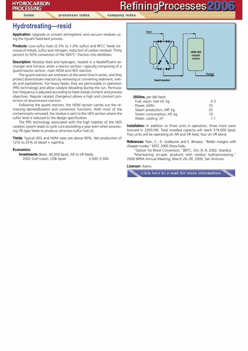
7/18/2019 Refining Processes Handbook 2006
http://slidepdf.com/reader/full/refining-processes-handbook-2006 155/222
Application: Upgrade or convert atmospheric and vacuum residues using the Hyvahl fixed-bed process.
Products: Low-sulfur fuels (0.3% to 1.0% sulfur) and RFCC feeds (re-
moval of metals, sulfur and nitrogen, reduction of carbon residue). Thirtypercent to 50% conversion of the 565°C+ fraction into distillates.
Description: Residue feed and hydrogen, heated in a feed/effluent ex-changer and furnace, enter a reactor section—typically comprising of aguard-reactor section, main HDM and HDS reactors.
The guard reactors are onstream at the same time in series, and theyprotect downstream reactors by removing or converting sediment, met-als and asphaltenes. For heavy feeds, they are permutable in operation(PRS technology) and allow catalyst reloading during the run. Permuta-
tion frequency is adjusted according to feed-metals content and processobjectives. Regular catalyst changeout allows a high and constant pro-tection of downstream reactors.
Following the guard reactors, the HDM section carries out the re-maining demetallization and conversion functions. With most of thecontaminants removed, the residue is sent to the HDS section where thesulfur level is reduced to the design specification.
The PRS technology associated with the high stability of the HDScatalytic system leads to cycle runs exceeding a year even when process-
ing VR-type feeds to produce ultra-low-sulfur fuel oil. Yields: Typical HDS and HDM rates are above 90%. Net production of12% to 25% of diesel + naphtha.
Economics:
Investments (Basis: 40,000 bpsd, AR to VR feeds,2002 Gulf coast), US$/ bpsd 3,500–5,500
Utilities, per bbl feed: Fuel, equiv. fuel oil, kg 0.3 Power, kWhr 10 Steam production, MP, kg 25 Steam consumption, HP, kg 10 Water, cooling, m3 1.1
Installation: In addition to three units in operation, three more werelicensed in 2005 / 06. Total installed capacity will reach 319,000 bpsd.Two units will be operating on AR and VR feed, four on VR alone.
References: Plain, C., D. Guillaume and E. Benaezi, “Better margins withcheaper crudes,” ERTC 2005 Show Daily.
“Option for Resid Conversion,” BBTC, Oct. 8 – 9, 2002, Istanbul.“Maintaining on-spec products with residue hydroprocessing,”
2000 NPRA Annual Meeting, March 26–28, 2000, San Antonio.
Licensor: Axens.
�
�
Hydrotreating—residueApplication: Upgrading or converting atmospheric and vacuum residues

7/18/2019 Refining Processes Handbook 2006
http://slidepdf.com/reader/full/refining-processes-handbook-2006 156/222
pp pg g g pusing the Genoil GHU process.
Products: Removal of metals, maximize desulfurization (>90%), deni-
trogenation (>70%), reduction of carbon residue (>90%) with API in-crease during the conversion process. Up to 90% conversion of 350°C+fraction into distillates.
Description: Genoil has developed devices that enhance the mixing ofliquid hydrocarbons as well as highly efficient reactor internals. Thesemodifications have contributed to the high level of residue conversion,desulfurization, denitrogenation and turnaround time.
Residue feed and hydrogen are heated in feed effluent exchangerand furnace and enter the reactor section. The reactor section is typically
comprised of a guard-section hydrodemineralization (HDM) reactor, andsulfur-removal section—hydrodesulfurization (HDS).
The guard-reactor section protects the downstream HDS reactors byremoving metals and asphaltenes. Catalyst and operational objectives canbe adjusted according to feed metals content through different mechani-cal means to insure longer runtimes and constant protection for down-stream reactors.
After the guard section carries out the final removal of metals andconversion, the HDS section removes the sulfur to design specifications.With these factors in mind, Genoil has come up with a hydroconversionprocess that provides higher conversion, higher desulfurization and de-nitrogenation rates at lower pressure by using a simple, easy to operateprocess.
The upgrading process can be used as a field upgrader where heavyoil can be upgraded to WTI specification, pipeline specifications and pipe-lined to refineries. Unconverted oil from the GHUunit can be sold as astable, low-sulfur fuel oil or sent to another heavy-oil conversion unit forfurther upgrading.
Yields: Net increase in production from 0 –10% naphtha, 1–20% kero-
sine and 21– 47% diesel.
Investment: Based on 20,000 bpd, atmospheric or vacuum or VR feeds,$3,000 – 5,000/bbl based of Gulf Coast rates.
Installations: Genoil owns and operates a 10 BPD demonstration plantat Two Hill, Alberta where we have conducted testing on several differ-ent types of residue and crudes shipped to our facility by various com-panies. We are currently working with several companies to get firstcommercial installation of the GHU process.
Reference: Asia Pacific Refining Conference Bangkok, Thailand, Sep-tember, 2005.
RPBC Moscow, Russia, April Conference 2006.Middle East Refining Conference, Doha, Qatar, May 2006. America Oil and Gas Reporter, October 2005.Energy Magazine, June 2005, Petroleum Technology Quarterly, Jan-
uary 2006.Oil & Gas Product News, “Surge Global Announcement,” Jan./Feb.
2005.
Licensor: Genoil Inc.
�
IsomerizationApplication: C5 /C6 paraffin-rich hydrocarbon streams are isomerized to

7/18/2019 Refining Processes Handbook 2006
http://slidepdf.com/reader/full/refining-processes-handbook-2006 157/222
pp 5 6 p yproduce high RON and MON product suitable for addition to the gaso-line pool.
Description: Several variations of the C5 / C6 isomerization process areavailable. The choice can be a once-through reaction for an inexpensive-but-limited octane boost, or, for substantial octane improvement and asan alternate (in addition) to the conventional DIH recycle option, the Ip-sorb Isom scheme shown to recycle the normal paraffins for their com-plete conversion. The Hexorb Isom configuration achieves a completenormal paraffin conversion plus substantial conversion of low (75) oc-tane methyl pentanes gives the maximum octane results. With the mostactive isomerization catalyst (chlorinated alumina), particularly with theAlbemarle /Axens jointly developed ATIS2L catalyst, the isomerizationperformance varies from 84 to 92: once-through isomerization -84,isomerization with DIH recycle -88, Ipsorb -90, Hexorb-92.
Operating conditions: The Ipsorb Isom process uses a deisopentanizer(1) to separate the isopentane from the reactor feed. A small amount ofhydrogen is also added to reactor (2) feed. The isomerization reactionproceeds at moderate temperature producing an equilibrium mixture ofnormal and isoparaffins. The catalyst has a long service life. The reactorproducts are separated into isomerate product and normal paraffins inthe Ipsorb molecular sieve separation section (3) which features a novelvapor phase PSA technique. This enables the product to consist entirelyof branched isomers.
Economics: (Basis: Ipsorb “A” Isomerization unit with a 5,000-bpsd 70RONC feed needing a 20-point octane boost):
Investment*, million US$ 13.6
Utilities: Steam, HP, tph 1.0 Steam, MP, tph 8.5
Steam, LP, tph 6.8
Power, kWh /h 310 Cooling water, m3 / h 100
* Mid-2002, Gulf coast, excluding cost of noble metals
Installation: Of 35 licenses issued for C5 / C6 isomerization plants, 14units are operating including one Ipsorb unit.
Reference: Axens /Albemarle, “Advanced solutions for paraffinisomerization,” NPRA Annual Meeting, March 2004, San Antonio.
“Paraffins isomerizatioin options,” Petroleum Technology Quarterly,Q2, 2005.
Licensor: Axens.
�
�
IsomerizationApplication: Convert normal olefins to isoolefins.
�

7/18/2019 Refining Processes Handbook 2006
http://slidepdf.com/reader/full/refining-processes-handbook-2006 158/222
pp
Description:
C4 olefin skeletal isomerization (ISOMPLUS)A zeolite-based catalyst especially developed for this process pro-
vides near equilibrium conversion of normal butenes to isobutylene athigh selectivity and long process cycle times. A simple process schemeand moderate process conditions result in low capital and operatingcosts. Hydrocarbon feed containing n-butenes, such as C4 raffinate, canbe processed without steam or other diluents, nor the addition of cata-lyst activation agents to promote the reaction. Near-equilibrium con-version levels up to 44% of the contained n-butenes are achieved atgreater than 90% selectivity to isobutylene. During the process cycle,
coke gradually builds up on the catalyst, reducing the isomerization ac-tivity. At the end of the process cycle, the feed is switched to a freshcatalyst bed, and the spent catalyst bed is regenerated by oxidizing thecoke with an air/nitrogen mixture. The butene isomerate is suitable formaking high purity isobutylene product.
C5 olefin skeletal isomerization (ISOMPLUS)A zeolite-based catalyst especially developed for this process pro-
vides near-equilibrium conversion of normal pentenes to isoamylene athigh selectivity and long process cycle times. Hydrocarbon feeds con-
taining n-pentenes, such as C5 raffinate, are processed in the skeletalisomerization reactor without steam or other diluents, nor the additionof catalyst activation agents to promote the reaction. Near-equilibriumconversion levels up to 72% of the contained normal pentenes are ob-served at greater than 95% selectivity to isoamylenes.
Economics: The ISOMPLUS process offers the advantages of low capitalinvestment and operating costs coupled with a high yield of isobutyleneor isoamylene. Also, the small quantity of heavy byproducts formed caneasily be blended into the gasoline pool. Capital costs (equipment, labor
and detailed engineering) for three different plant sizes are:
Total installed cost: Feedrate, Mbpd ISBL cost, $MM 10 8 15 11 30 20
Utility consumption: per barrel of feed (assuming an electric-motor-driven compressor) are:
Power, kWh 3.2Fuel gas, MMBtu 0.44
Steam, MP, MMBtu 0.002Water, cooling, MMBtu 0.051Nitrogen, scf 57–250
Installation: Two plants are in operation. Two licensed units are in vari-ous stages of design.
Licensor: CDTECH and Lyondell Chemical Co.
�
IsomerizationApplication: Hydrisom is the ConocoPhillips selective diolefin hydroge-

7/18/2019 Refining Processes Handbook 2006
http://slidepdf.com/reader/full/refining-processes-handbook-2006 159/222
pp y p y gnation process, with specific isomerization of butene-1 to butene-2 and3-methyl-butene-1 to 2-methyl-butene-1 and 2-methyl-butene-2. TheHydrisom Process uses a liquid-phase reaction over a commercially avail-able catalyst in a fixed-bed reactor.
Description: The ConocoPhillips Hydrisom Process is a once-through re-action and, for typical cat cracker streams, requires no recycle or cooling.Hydrogen is added downstream of the olefin feed pump on ratio controland the feed mixture is preheated by exchange with the fractionatorbottoms and/or low-pressure steam. The feed then flows downwardover a fixed bed of commercial catalyst.
The reaction is liquid-phase, at a pressure just above the bubblepoint of the hydrocarbon/hydrogen mixture. The rise in reactor tem-perature is a function of the quantity of butadiene in the feed and theamount of butene saturation that occurs.
The Hydrisom Process can also be configured using a proprietarycatalyst to upgrade streams containing diolefins up to 50% or more,e.g., steam cracker C4 steams, producing olefin-rich streams for use aschemical, etherification and/or alkylation feedstocks.
Installation of a Hydrisom unit upstream of an etherification and/ or alkylation unit can result in a very quick payout of the investmentdue to:
• Improved etherification unit operations• Increased ether production• Increased alkylate octane number• Increased alkylate yield• Reduced chemical and HF acid costs• Reduced ASO handling• Reduced alkylation unit utilities• Upgraded steam cracker or other high diolefin streams (30% to
50%) for further processing.
Installation: Ten units licensed worldwide, including an installation atthe ConocoPhillips Sweeny, Texas, Refinery.
Licensor: ConocoPhillips.
�
IsomerizationApplication: The widely used Butamer process is a high-efficiency, cost

7/18/2019 Refining Processes Handbook 2006
http://slidepdf.com/reader/full/refining-processes-handbook-2006 160/222
pp y p g y,effective means of meeting the demands for the production of isobu-tane by isomerizing normal butane (nC4) to isobutane (iC4).
Motor-fuel alkylate is one blending component that has seen a sub-stantial increase in demand because of its paraffinic, high-octane, low-vapor pressure blending properties. Isobutane is a primary feedstock forproducing motor-fuel alkylate.
Description: UOP’s innovative hydrogen-once-through (HOT) Butamer pro-cess results in substantial savings in capital equipment and utility costs byeliminating the need for a product separator or recycle-gas compressor.
Typically, two reactors, in series flow, are used to achieve highonstream efficiency. The catalyst can be replaced in one reactor whileoperation continues in the other. The stabilizer separates the light gas
from the reactor effluent.A Butamer unit can be integrated with an alkylation unit. In this
application, the Butamer unit feed is a side-cut from an isostripper col-umn, and the stabilized isomerate is returned to the isostripper column.Unconverted n-butane is recycled to the Butamer unit, along with n-bu-tane from the fresh feed. Virtually complete conversion of n-butane toisobutane can be achieved.
Feed: The best feeds for a Butamer unit contain the highest practicaln-butane content, and only small amounts of isobutane, pentanes and
heavier material. Natural gas liquids (NGL) from a UOP NGL recovery unitcan be processed in a Butamer unit.
Yield: The stabilized isomerate is a near-equilibrium mixture of isobutaneand n-butane with small amounts of heavier material. The light-endsyield from cracking is less than 1 wt% of the butane feed.
Installation: More than 70 Butamer units have been commissioned, andadditional units are in design or construction. Butamer unit feed capaci-ties range from 800 to 35,000+ bpsd (74 to 3,250 tpd).
Licensor: UOP LLC.
�
IsomerizationApplication: The Par-Isom process is an innovative application using

7/18/2019 Refining Processes Handbook 2006
http://slidepdf.com/reader/full/refining-processes-handbook-2006 161/222
high-performance nonchlorided-alumina catalysts for light-naphthaisomerization. The process uses PI-242 catalyst, which approaches theactivity of chlorided alumina catalysts without requiring organic chlorideinjection. The catalyst is regenerable and is sulfur and water tolerant.
Description: The fresh C5 / C6 feed is combined with make-up and re-cycle hydrogen which is directed to a charge heater, where the reactantsare heated to reaction temperature. The heated combined feed is thensent to the reactor. Either one or two reactors can be used in series, de-pending on the specific application.
The reactor effluent is cooled and sent to a product separator wherethe recycle hydrogen is separated from the other products. Recoveredrecycle hydrogen is directed to the recycle compressor and back to thereaction section. Liquid product is sent to a stabilizer column where lightends and any dissolved hydrogen are removed. The stabilized isomerateproduct can be sent directly to gasoline blending.
Feed: Typical feed sources for the Par-Isom process include hydrotreatedlight straight-run naphtha, light natural gasoline or condensate and lightraffinate from benzene extraction units.
Water and oxygenates at concentrations of typical hydrotreatednaphtha are not detrimental, although free water in the feedstock mustbe avoided. Sulfur suppresses activity, as expected, for any noble-metalbased catalyst. However, the suppression effect is fully reversible by sub-sequent processing with clean feedstocks.
Yield: Typical product C5+ yields are 97 wt% of the fresh feed. Theproduct octane is 81 to 87, depending on the flow configuration andfeedstock qualities.
Installation: The first commercial Par-Isom process unit was placed inoperation in 1996. There are currently 10 units in operation. The firstcommercial application of PI-242 catalyst was in 2003, and the unit hasdemonstrated successful performance meeting all expectations.
Licensor: UOP LLC.
�
IsomerizationApplication: Most of the implemented legislation requires limiting

7/18/2019 Refining Processes Handbook 2006
http://slidepdf.com/reader/full/refining-processes-handbook-2006 162/222
benzene concentration in the gasoline pool. This has increased thedemand for high-performance C5 and C6 naphtha isomerization tech-nology because of its ability to reduce the benzene concentration inthe gasoline pool while maintaining or increasing the pool octane. ThePenex process has served as the primary isomerization technology forupgrading C5 / C6 light straight-run naphtha.
Description: UOP’s innovative hydrogen-once-through (HOT) Penex pro-cess results in sustantial savings in capital equipment and utility costs byeliminating the need for a product separator or recycle-gas compressor.The Penex process is a fixed-bed process that uses high-activity chlo-ride-promoted catalysts to isomerize C5 / C6 paraffins to higher-octane-branched components. The reaction conditions promote isomerizationand minimize hydrocracking.
Typically, two reactors, in series flow, are used to achieve highonstream efficiency. The catalyst can be replaced in one reactor whileoperation continues in the other. The stabilizer separates light gas fromthe reactor effluent.
Products: For typical C5 / C6 feeds, equilibrium will limit the product to83 to 86 RONC on a single hydrocarbon pass basis. To achieve higheroctane, UOP offers several schemes in which lower octane componentsare separated from the reactor effluent and recycled back to the reac-tors. These recycle modes of operation can lead to product octane ashigh as 93 RONC, depending on feed quality.
Yields:Penex process: Octane 86Penex process/DIH: Octane 90Penex process/Molex process: Octane 91DIP/Penex process/DIH: Octane 93
Feed: Penex process can process feeds with high levels of C6 cyclics andC7 components. In addition, feeds with substantial levels of benzenecan be processed without the need for a separate saturation section.
Installation: UOP is the leading world-wide provider of isomerization tech-nology. More than 120 Penex units are in operation. Capacities rangefrom 1,000 bpsd to more than 25,000 bpsd of fresh feed capacity.
Licensor: UOP LLC.
�
Isooctene/isooctaneApplication: New processes, RHT-isooctene and RHT-isooctane, can be
d i i MTBE i i /i d i

7/18/2019 Refining Processes Handbook 2006
http://slidepdf.com/reader/full/refining-processes-handbook-2006 163/222
used to revamp existing MTBE units to isooctene/isooctane production.Feeds include C4 iso-olefin feed from FCC, steam crackers, thermalcrackers or on-purpose iso-butylene from dehydrogenation units. The
processes uses a unique configuration for dimerization. A new selectiva-tor is used, together with a dual-bed catalyst.
The configuration is capable of revamping conventional or reactivedistillation MTBE units. The process provides higher conversion, betterselectivity, conventional catalyst, and a new selectivator supports withlonger catalyst life with a dual catalyst application.
The process is designed to apply a hydrogenation unit to convertisooctene into isooctane, if desired, by utilizing a dual-catalyst system,in the first and finishing reactors. The process operates at lower pressure
and provides lower costs for the hydrogenation unit.Description: The feed is water washed to remove any basic compoundsthat can poison the catalyst system. Most applications will be directedtoward isooctene production. However as olefin specifications are re-quired, the isooctene can be hydrogenated to isooctane, which is anexcellent gasoline blending stock.
The RHT isooctene process has a unique configuration; it is flexibleand can provide low per pass conversion through dilution, using a newselectivator. The dual catalyst system also provides multiple advantages.
The isobutylene conversion is 97–99 %, with better selectivity and yieldtogether with enhanced catalyst life. The product is over 91% C8 olefins,and 5 – 9% C12 olefins, with very small amount of C16 olefins.
The feed after water wash, is mixed with recycle stream, whichprovides the dilution (also some unreacted isobutylene) and is mixedwith a small amount of hydrogen. The feed is sent to the dual-bed re-actor for isooctene reaction in which most of isobutylene is convertedto isooctene and codimer. The residual conversion is done with single-resin catalyst via a side reactor. The feed to the side reactor is taken asa side draw from the column and does contain unreacted isobutylene,
selectivator, normal olefins and non-reactive C4s. The recycle stream
provides the dilution, and reactor effluent is fed to the column at mul-tiple locations. Recycling does not increase column size due to the
unique configuration of the process. The isooctene is taken from thedebutanizer column bottom and is sent to OSBL after cooling or as issent to hydrogenation unit. The C4s are taken as overhead stream andsent to OSBL or alkylation unit. Isooctene/product, octane (R+M)/2 isexpected to be about 105.
If isooctane is to be produced the debutanizer bottom, isoocteneproduct is sent to hydrogenation unit. The isooctene is pumped to therequired pressure (which is much lower than conventional processes),mixed with recycle stream and hydrogen and is heated to the reaction
�
�
�
Continued
Economics: Isooctene Isooctane1
CAPEX ISBL, MM USD(US Gulf Coast 1Q 06, 1,000 bpd) 8.15 5.5
Utilities basis 1,000-bpd isooctene/isooctane Power, kWh 65 105 Water, cooling, m3 /h 154 243
temperature before sending it the first hydrogenation reactor. This reac-tor uses a nickel (Ni) or palladium (Pd) catalyst.
If feed is coming directly from the isooctene unit, only a start-upheater is required. The reactor effluent is flashed, and the vent is sentto OSBL. The liquid stream is recycled to the reactor after cooling (to
h t f ti ) d ti i f d d t th fi i hi
Isooctene/Isooctane, continued

7/18/2019 Refining Processes Handbook 2006
http://slidepdf.com/reader/full/refining-processes-handbook-2006 164/222
Steam, HP, kg/h 3,870 4,650Basis: FCC feed (about 15 –20% isobutelene in C4 mixed stream)1These util ities are for isooctene / isooctane cumulative.
Installation: Technology is ready for commercial application.
Licensor: Refining Hydrocarbon Technologies LLC.
remove heat of reaction) and a portion is forwarded to the finishingreactor—which also applies a Ni or Pd catalyst (preferably Pd catalyst) —and residual hydrogenation to isooctane reaction occurs. The isooctane
product, octane (R+M)/2 is >98.The reaction occurs in liquid phase or two phase (preferably two
phases), which results in lower pressure option. The olefins in isoocteneproduct are hydrogenated to over 99%. The finishing reactor effluent issent to isooctane stripper, which removes all light ends, and the productis stabilized and can be stored easily.

7/18/2019 Refining Processes Handbook 2006
http://slidepdf.com/reader/full/refining-processes-handbook-2006 165/222
Lube extractionApplication: Bechtel’s MP Refining process is a solvent-extraction pro-
th t N th l 2 lid (NMP) th l t t l
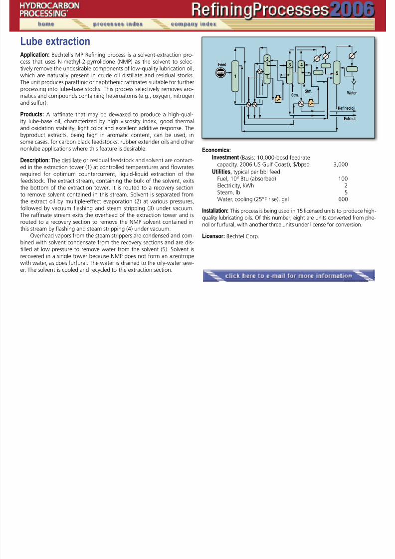
7/18/2019 Refining Processes Handbook 2006
http://slidepdf.com/reader/full/refining-processes-handbook-2006 166/222
cess that uses N-methyl-2-pyrrolidone (NMP) as the solvent to selec-tively remove the undesirable components of low-quality lubrication oil,which are naturally present in crude oil distillate and residual stocks.The unit produces paraffinic or naphthenic raffinates suitable for furtherprocessing into lube-base stocks. This process selectively removes aro-matics and compounds containing heteroatoms (e.g., oxygen, nitrogenand sulfur).
Products: A raffinate that may be dewaxed to produce a high-qual-ity lube-base oil, characterized by high viscosity index, good thermaland oxidation stability, light color and excellent additive response. Thebyproduct extracts, being high in aromatic content, can be used, insome cases, for carbon black feedstocks, rubber extender oils and othernonlube applications where this feature is desirable.
Description: The distillate or residual feedstock and solvent are contact-ed in the extraction tower (1) at controlled temperatures and flowratesrequired for optimum countercurrent, liquid-liquid extraction of thefeedstock. The extract stream, containing the bulk of the solvent, exitsthe bottom of the extraction tower. It is routed to a recovery sectionto remove solvent contained in this stream. Solvent is separated fromthe extract oil by multiple-effect evaporation (2) at various pressures,followed by vacuum flashing and steam stripping (3) under vacuum.The raffinate stream exits the overhead of the extraction tower and isrouted to a recovery section to remove the NMP solvent contained inthis stream by flashing and steam stripping (4) under vacuum.
Overhead vapors from the steam strippers are condensed and com-bined with solvent condensate from the recovery sections and are dis-tilled at low pressure to remove water from the solvent (5). Solvent isrecovered in a single tower because NMP does not form an azeotropewith water, as does furfural. The water is drained to the oily-water sew-er. The solvent is cooled and recycled to the extraction section.
Economics:
Investment (Basis: 10,000-bpsd feedratecapacity, 2006 US Gulf Coast), $/bpsd 3,000
Utilities, typical per bbl feed: Fuel, 103 Btu (absorbed) 100 Electricity, kWh 2 Steam, lb 5 Water, cooling (25°F rise), gal 600
Installation: This process is being used in 15 licensed units to produce high-quality lubricating oils. Of this number, eight are units converted from phe-nol or furfural, with another three units under license for conversion.
Licensor: Bechtel Corp.
�
�
�
Continued
Lube extractionApplication: Bechtel’s Furfural Refining process is a solvent-extraction
h f f l h l l i l d i

7/18/2019 Refining Processes Handbook 2006
http://slidepdf.com/reader/full/refining-processes-handbook-2006 167/222
process that uses furfural as the solvent to selectively remove undesir-able components of low lubrication oil quality, which are naturally pres-ent in crude oil distillate and residual stocks. This process selectively re-moves aromatics and compounds containing heteroatoms (e.g., oxygen,nitrogen and sulfur). The unit produces paraffinic raffinates suitable forfurther processing into lube base stocks.
Products: A raffinate that may be dewaxed to produce a high-qual-ity lube-base oil, characterized by high viscosity index, good thermaland oxidation stability, light color and excellent additive response. Thebyproduct extracts, being high in aromatic content, can be used, insome cases, for carbon black feedstocks, rubber extender oils and othernonlube applications where this feature is desirable.
Description: The distillate or residual feedstock and solvent are contact-ed in the extraction tower (1) at controlled temperatures and flowratesrequired for optimum countercurrent, liquid-liquid extraction of thefeedstock. The extract stream, containing the bulk of the solvent, exitsthe bottom of the extraction tower. It is routed to a recovery section toremove solvent contained in this stream. Solvent is separated from theextract oil by multiple-effect evaporation (2) at various pressures, fol-lowed by vacuum flashing and steam stripping (3) under vacuum. The
raffinate stream exits the overhead of the extraction tower and is routedto a recovery section to remove the furfural solvent contained in thisstream by flashing and steam stripping (4) under vacuum.
The solvent is cooled and recycled to the extraction section. Over-head vapors from the steam strippers are condensed and combined withthe solvent condensate from the recovery sections and are distilled atlow pressure to remove water from the solvent. Furfural forms an azeo-trope with water and requires two fractionators. One fractionator (5)separates the furfural from the azeotrope, and the second (6) separateswater from the azeotrope. The water drains to the oily-water sewer. The
solvent is cooled and recycled to the extraction section.
Economics:
Investment (Basis: 10,000-bpsd feed rate capacity,2006 US Gulf Coast), $/ bpsd 3,100
Utilities, typical per bbl feed: Fuel, 103 Btu (absorbed) 120 Electricity, kWh 2
Steam, lb 5 Water, cooling (25°F rise), gal 650
Installation: For almost 60 years, this process has been or is being usedin over 100 licensed units to produce high-quality lubricating oils.
Licensor: Bechtel Corp.
�
��
�
Lube hydrotreatingApplication: The Bechtel Hy-Finishing process is a specialized hydrotreatingtechnology to remove impurities and improve the quality of paraffinic

7/18/2019 Refining Processes Handbook 2006
http://slidepdf.com/reader/full/refining-processes-handbook-2006 168/222
technology to remove impurities and improve the quality of paraffinicand naphthenic lubricating base oils. In the normal configuration, thehydrogen finishing unit is located in the processing scheme between thesolvent extraction and solvent dewaxing units for a lube plant operatingon an approved lube crude. In this application, the unit operates undermild hydrotreating conditions to improve color and stability, to reducesulfur, nitrogen, oxygen and aromatics, and to remove metals.
Another application is Hy-Starting, which is a more severe hydro-treating process (higher pressure and lower space velocity) and upgradesdistillates from lower-quality crudes. This unit is usually placed beforesolvent extraction in the processing sequence to upgrade distillate qual-ity and, thus, improve extraction yields at the same raffinate quality.
Description: Hydrocarbon feed is mixed with hydrogen (recycle plusmakeup), preheated, and charged to a fixed-bed hydrotreating reac-tor (1). Reactor effluent is cooled in exchange with the mixed feed-hy-drogen stream. Gas-liquid separation of the effluent occurs first in thehot separator (2) then in the cold separator (3). The hydrocarbon liquidstream from each of the two separators is sent to the product stripper (4)to remove the remaining gas and unstabilized distillate from the lube-oilproduct. The product is then dried in a vacuum flash (5). Gas from thecold separator is amine-scrubbed (6) to remove H2S before compression
in the recycle hydrogen compressor (7).Economics:
Investment (Basis 7,000-bpsd feedrate capacity, 2006 US Gulf Coast), $/bpsd 5,100
Utilities, typical per bbl feed: Fuel, 103 Btu (absorbed) 20 Electricity, kWh 5 Steam, lb 15 Water, cooling (25°F rise), gal 400
Licensor: Bechtel Corp.
�
�
Lube hydrotreatingApplication: Hy-Raff is a new process to hydrotreat raffinates from anextraction unit of a solvent based lube oil plant for upgrading standard

7/18/2019 Refining Processes Handbook 2006
http://slidepdf.com/reader/full/refining-processes-handbook-2006 169/222
extraction unit of a solvent-based lube oil plant for upgrading standardGroup I lube-base oils to produce Group II base oils. Sulfur is reduced tobelow 0.03 wt% and saturates are increased to greater than 90 wt%.The integration of this process into an existing base oil plant allowsthe operator to cost-effectively upgrade base-oil products to the newspecifications rather than scrapping the existing plant and building anexpensive new hydrocracker-based plant.
The product from the Hy-Raff unit is a lube-base oil of sufficientquality to meet Group II specifications. The color of the finished prod-uct is significantly improved over standard-base oils. Middle distillatebyproducts are of sufficient quality for blending into diesel.
Description: Raffinate feed is mixed with hydrogen (recycle plus make-up), preheated, and charged to a fixed-bed hydrotreating reactor (1).The reactor effluent is cooled in exchange with the mixed feed-hydrogenstream. Gas-liquid separation of the effluent occurs first in the hot sepa-rator (2) then in the cold separator (3). The hydrocarbon liquid streamfrom each of the two separators is sent to the product stripper (4) toremove the remaining gas and unstabilized distillate from the lube-oilproduct, and product is dried in a vacuum flash (5). Gas from the coldseparator is amine-scrubbed (6) for removal of H2S before compressionin the recycle-hydrogen compressor (7).
Economics:
Investment (Basis 7,000-bpsd feedrate capacity, 2006 U.S. Gulf Coast), $/bpsd 7,100
Utilitiies, typical per bbl feed: Fuel, 103 Btu (absorbed) 70 Electricity, kWh 5 Steam, lb 15 Water, cooling (25°F rise), gal 200
Licensor: Bechtel Corp.
�
�
Lube oil refining, spentApplication: The Revivoil process can be used to produce high yields ofpremium quality lube bases from spent motor oils Requiring neither

7/18/2019 Refining Processes Handbook 2006
http://slidepdf.com/reader/full/refining-processes-handbook-2006 170/222
premium quality lube bases from spent motor oils. Requiring neitheracid nor clay treatment steps, the process can eliminate environmentaland logistical problems of waste handling and disposal associated with
conventional re-refining schemes.
Description: Spent oil is distilled in an atmospheric flash distillationcolumn to remove water and gasoline and then sent to the ThermalDeasphalting (TDA) vacuum column for recovery of gas oil overheadand oil bases as side streams. The energy-efficient TDA column featuresexcellent performance with no plugging and no moving parts. Metalsand metalloids concentrate in the residue, which is sent to an optionalSelectopropane unit for brightstock and asphalt recovery. This schemeis different from those for which the entire vacuum column feed goes
through a deasphalting step; Revivoil’s energy savings are significant,and the overall lube oil base recovery is maximized. The results are sub-stantial improvements in selectivity, quality and yields.
The final, but very important step for base oil quality is a specifichydrofinishing process that reduces or removes remaining metals andmetalloids, Conradson Carbon, organic acids, and compounds contain-ing chlorine, sulfur and nitrogen. Color, UV and thermal stability arerestored and polynuclear aromatics are reduced to values far below thelatest health thresholds. Viscosity index remains equal to or better than
the original feed. For metal removal (> 96%) and refining-purificationduty, the multicomponent catalyst system is the industry’s best.
Product quality: The oil bases are premium products; all lube oil basespecifications are met by Revivoil processing from Group 1 throughGroup 2 of the API basestocks definitions. Besides, a diesel can be ob-tained, in compliance with the EURO 5 requirements (low sulfur).
Health & safety and environment: The high-pressure process is in linewith future European specifications concerning carcinogenic PNA com-
pounds in the final product at a level inferior to 5 wppm (less than 1wt% PCA - IP346 method).
Economics: The process can be installed stepwise or entirely. A simplerscheme consists of the atmospheric flash, TDA and hydrofinishing unitand enables 70 – 80% recovery of lube oil bases. The Selectopropane
unit can be added at a later stage, to bring the oil recovery to the 95%level on dry basis. Economics below show that for two plants of equalcapacity, payout times before taxes are two years in both cases.
Investment: Basis 100,000 metric tpy, water-free, ISBL 2004 GulfCoast, million US$
Configuration 1 (Atm. flash, TDA and Hydrofinishing units) 30
Configuration 2 (Same as above + Selectopropane unit) 35
�
Continued
Utilities: Basis one metric ton of water-free feedstock
Config. 1 Config. 2Electrical power, kWh 45 55Fuel, million kcal 0.62 0.72Steam LP kg 23 2
Lube oil refining, spent, continued

7/18/2019 Refining Processes Handbook 2006
http://slidepdf.com/reader/full/refining-processes-handbook-2006 171/222
Steam, LP, kg — 23.2Steam, MP, kg 872 890Water, cooling, m3 54 59
Installation: Ten units have been licensed using all or part of the RevivoilTechnology.
Licensor: Axens and Viscolube SpA.
Lube treatingApplication: Lube raffinates from extraction are dewaxed to provide base-stocks having low pour points (as low as 35°C) Basestocks range from
�

7/18/2019 Refining Processes Handbook 2006
http://slidepdf.com/reader/full/refining-processes-handbook-2006 172/222
stocks having low pour points (as low as –35 C). Basestocks range fromlight stocks (60N) to higher viscosity grades (600N and bright stock).Byproduct waxes can also be upgraded for use in food applications.
Feeds: DILCHILL dewaxing can be used for a wide range of stocks that boilabove 550°F, from 60N up through bright stock. In addition to raffinatesfrom extraction, DILCHILL dewaxing can be applied to hydrocracked stocksand to other stocks from raffinate hydroconversion processes.
Processes: Lube basestocks have low pour points. Although slack wax-es containing 2–10 wt% residual oil are the typical byproducts, lower-oil-content waxes can be produced by using additional dewaxing and/or“warm-up deoiling” stages.
Description: DILCHILL is a novel dewaxing technology in which wax crystalsare formed by cooling waxy oil stocks, which have been diluted with ketonesolvents, in a proprietary crystallizer tower that has a number of mixingstages. This nucleation environment provides crystals that filter more quicklyand retain less oil. This technology has the following advantages over con-ventional incremental dilution dewaxing in scraped-surface exchangers: lessfilter area is required, less washing of the filter cake to achieve the sameoil-in-wax content is required, refrigeration duty is lower, and only scrapedsurface chillers are required which means that unit maintenance costs are
lower. No wax recrystallization is required for deoiling.Warm waxy feed is cooled in a prechiller before it enters the DILCHILL
crystallizer tower. Chilled solvent is then added in the crystallizer towerunder highly agitated conditions. Most of the crystallization occurs inthe crystallizer tower. The slurry of wax/oil/ketone is further cooled inscraped-surface chillers and the slurry is then filtered in rotary vacuumfilters. Flashing and stripping of products recover solvent. Additional fil-tration stages can be added to recover additional oil or/to produce low-oil content saleable waxes.
Economics: Depend on the slate of stocks to be dewaxed, the pourpoint targets and the required oil-in-wax content.
Utilities: Depend on the slate of stocks to be dewaxed, the pour pointtargets and the required oil-in-wax content.
Installation: The first application of DILCHILL dewaxing was the conver-sion of an ExxonMobil affiliate unit on the U.S. Gulf Coast in 1972. Sincethat time, 10 other applications have been constructed. These applica-tions include both grassroots units and conversions of incremental dilu-tion plants. Six applications use “warm-up deoiling.”
Licensor: ExxonMobil Research and Engineering Co.
�
Lube treatingApplication: Process to produce lube oil raffinates with high viscosityindex from vacuum distillates and deasphalted oil

7/18/2019 Refining Processes Handbook 2006
http://slidepdf.com/reader/full/refining-processes-handbook-2006 173/222
index from vacuum distillates and deasphalted oil.
Feeds: Vacuum distillate lube cuts and deasphalted oils.
Products: Lube oil raffinates of high viscosity indices. The raffinates con-tain substantially all of the desirable lubricating oil components presentin the feedstock. The extract contains a concentrate of aromatics thatmay be utilized as rubber oil or cracker feed.
Description: This liquid-liquid extraction process uses furfural or N-methyl pyrrolidone (NMP) as the selective solvent to remove aromat-ics and other impurities present in the distillates and deasphalted oils.The solvents have a high solvent power for those components that areunstable to oxygen as well as for other undesirable materials includ-ing color bodies, resins, carbon-forming constituents and sulfur com-pounds. In the extraction tower, the feed oil is introduced below the topat a predetermined temperature. The raffinate phase leaves at the topof the tower, and the extract, which contains the bulk of the furfural, iswithdrawn from the bottom. The extract phase is cooled and a so-called“pseudo raffinate“ may be sent back to the extraction tower. Multi-stage solvent recovery systems for raffinate and extract solutions secureenergy efficient operation.
Utility requirements (typical, Middle East Crude), units per m3 of feed: Electricity, kWh 10 Steam, MP, kg 10 Steam, LP, kg 35 Fuel oil, kg 20 Water, cooling, m3 20
Installation: Numerous installations using the Uhde (Edeleanu) propri-etary technology are in operation worldwide. The most recent is a com-plete lube-oil production facility licensed to the state of Turkmenistan.
Licensor: Uhde GmbH.
�
Mercaptan removalApplication: Extraction of mercaptans from gases, LPG, lower boilingfractions and gasolines or sweetening of gasoline jet fuel and diesel by

7/18/2019 Refining Processes Handbook 2006
http://slidepdf.com/reader/full/refining-processes-handbook-2006 174/222
fractions and gasolines, or sweetening of gasoline, jet fuel and diesel byin situ conversion of mercaptans into disulfides.
Products: Essentially mercaptan sulfur-free, i.e., less than 5 ppmw, andconcomitant reduced total sulfur content when treated by Merox ex-traction technique.
Description: Merox units are designed in several flow configurations,depending on feedstock type and processing objectives. All are charac-terized by low capital and operating costs, ease of operation and mini-mal operator attention.
Extraction: Gases, LPG and light naphtha are countercurrently extracted
(1) with caustic containing Merox catalyst. Mercaptans in the rich causticare oxidized (2) with air to disulfides that are decanted (3) before theregenerated caustic is recycled.
Sweetening: Minalk is now the most prevalent Merox gasoline sweeten-ing scheme. Conversion of mercaptans into disulfides is accomplishedwith a fixed bed of Merox catalyst that uses air and a continuous injec-tion of only minute amounts of alkali. Sweetened gasoline from thereactor typically contains less than one ppm sodium.
Heavy gasoline, condensate, kerosine/jet fuel and diesel can be
sweetened in a fixed-bed unit that closely resembles Minalk, except thata larger amount of more concentrated caustic is recirculated intermit-tently over the catalyst bed. A new additive, Merox Plus catalyst activa-tor, can be used to greatly extend catalyst life.
Economics: Typical capital investment and operating costs of someMerox process schemes are given based on 2004 dollars for a 10,000-bpsd capacity liquid unit and 10 million-scfd gas unit with modular de-sign and construction.
Heavy
naphtha
Product Gas LPG Gasoline fixed bedScheme Ext. Ext. MinalkEst. plant capital, modular $103 2,600 2,000 1,100 1,500Direct operating cost, ¢/bbl (¢/106 scf) (1.5) 0.4 0.2 1.0
Installations: Capacity installed and under construction exceeds 13 millionbpsd. More than 1,600 units have been commissioned to date, with capaci-ties between 40 and 140,000 bpsd. UOP has licensed gas Merox extractionunits with capacities as high as 2.9-billion-scfd for mercaptan control.
Licensor: UOP LLC.
�
�
NOx abatementApplication: Flue gases are treated with ammonia via ExxonMobil’s propri-etary selective noncatalytic NOx reduction technology—THERMAL DeNOx

7/18/2019 Refining Processes Handbook 2006
http://slidepdf.com/reader/full/refining-processes-handbook-2006 175/222
etary selective noncatalytic NOx reduction technology THERMAL DeNOx.NOx plus ammonia (NH3) are converted to elemental nitrogen and waterif temperature and residence time are appropriate. The technology hasbeen widely applied since it was first commercialized in 1974.
Products: If conditions are appropriate, the flue gas is treated to achieveNOx reductions of 40% to 70%+ with minimal NH3 slip or leakage.
Description: The technology involves the gas-phase reaction of NO withNH3 (either aqueous or anhydrous) to produce elemental nitrogen if con-ditions are favorable. Ammonia is injected into the flue gas using steamor air as a carrier gas into a zone where the temperature is 1,600°Fto 2,000°F. This range can be extended down to 1,300°F with a small
amount of hydrogen added to the injected gas. For most applications,wall injectors are used for simplicity of operation.
Yield: Cleaned flue gas with 40% to 70%+ NOx reduction and less than10-ppm NH3 slip.
Economics: Considerably less costly than catalytic systems but relativelyvariable depending on scale and site specifics. Third-party studies haveestimated the all-in cost at about 600 US$ / ton of NOx removed.
Installation: Over 135 applications on all types of fired heaters, boilersand incinerators with a wide variety of fuels (gas, oil, coal, coke, woodand waste). The technology can also be applied to full-burn FCCU re-generators.
Reference: McIntyre, A. D., “Applications of the THERMAL DeNOx pro-cess to utility and independent power production boilers,” ASME JointInternational Power Generation Conference, Phoenix, 1994.
McIntyre, A. D., “The THERMAL DeNOx process: Liquid fuels appli-cations,” International Flame Research Foundation’s 11th Topic Oriented
Technical Meeting, Biarritz, France, 1995.
McIntyre, A. D., “Applications of the THERMAL DeNOx process toFBC boilers,” CIBO 13th Annual Fluidized Bed Conference, Lake Charles,Louisiana, 1997.
Licensor: ExxonMobil Research and Engineering Co., via an alliance with
Engineers India Ltd. (for India) and Hamon Research-Cottrell (for the restof the world).
�
�
�

7/18/2019 Refining Processes Handbook 2006
http://slidepdf.com/reader/full/refining-processes-handbook-2006 176/222
Oxygen enrichment for Claus unitsApplication: Increase the capacity of Claus plants and decompose haz-ardous materials such as ammonia
Liquid oxygen tank
VaporizerClaus plant process
control system
C t ll

7/18/2019 Refining Processes Handbook 2006
http://slidepdf.com/reader/full/refining-processes-handbook-2006 177/222
Description: As “clean fuels” regulations become effective, refiners
must recover more sulfur in their Claus plants. As a byproduct of deepdesulfurization, ammonia is generated and typically must be decom-posed in the Claus plant. To upgrade the sulfur recovery units (SRUs)accordingly, oxygen enrichment is an effcient and low-cost option.Oxygen enrichment can increase sulfur capacity substantially and iscapable of decomposing ammonia from sour-water stripper gas veryefficiently.
Oxygen addition can be done in three levels, depending on therequired capacity increase:
1. Up to approximately 28% oxygen. Oxygen is simply added to
the Claus furnace air. This can raise sulfur capacity by up to 25%.2. Up to approximately 40% oxygen. The burner of the Claus fur-
nace must be replaced. Up to 50% additional sulfur capacity can beachieved by this method.
3. Beyond 40% oxygen. The temperature in the Claus furnace iselevated so high that the product gas must be recycled to maintaintemperature control. This process is expensive and, therefore, rarelyapplied.
Oxygen sources can be liquid oxygen tanks, onsite ASUs or pipe-
line supply. Oxygen consumption in Claus plants fluctuates widely inmost cases; thus, tanks are the best choice due to ease of operation,flexibility and economy. For oxygen addition into the CS air duct, anumber of safety rules must be observed. The oxygen metering deviceFLOWTRAIN contains all of the necessary safety features, includingflow control, low-temperature and low-pressure alarm and switch-off,and safe standby operation. All features are connected to the Clausplants’ process control system.
An effcient mixing device ensures even oxygen distribution in theClaus air. A proprietary Claus burner was developed especially for ap-
plication for air- and oxygen-enriched operations. This burner provides
for a short and highly turbulent flame, which ensures good approachtoward equilibrium for Claus operation and for the decomposition ofammonia.
Economics: As oxygen enrichment provides substantial additional
Claus capacity, it is a low-cost alternative to building an additional Clausplant. It can save investment, manpower and maintenance. Installedcost for oxygen enrichment per level 1 is typically below $250,000.For level 2, the investment costs range from $200,000 to $500,000and depend on the size of the Claus plant. Operating costs are variedand depend on the duration of oxygen usage. Typically, annual costsof oxygen enrichment are estimated as 10% to 40% of the cost for aClaus plant, providing the same additional sulfur capacity. Due to im-proved ammonia destruction maintenance work, as cleaning of heat
Measuring andcontrol unitFLOWTRAIN
Onsite ASU
1 Alternative oxygen sources2 FLOWTRAIN with all required safety features
3 Oxygen injection and mixing device4 Claus reaction furnace with burner for air and/or oxygen enriched operation
Oxygen pipeline Acid gas plus sour
water stripper gas
Air
BFW
Steam
4
3
1
2 Process gasto catalytic
reactors
Controller
Continued
exchanger tubes from ammonium salts and the respective corrosionbecome substantially less.
Installations: Over 10, plus numerous test installations to quantify theeffects of capacity increase and ammonia decomposition.
Oxygen enrichment for Claus units, continued

7/18/2019 Refining Processes Handbook 2006
http://slidepdf.com/reader/full/refining-processes-handbook-2006 178/222
Reference: Reinhardt, H. J. and P. M. Heisel, “Increasing the capacity ofClaus plants with oxygen,” Reports on Science and Technology, No. 61
(1999), p. 2.
Contributor: Linde AG, Division Gas and Engineering.
Oxygen enrichment for FCC unitsApplication: Increase the throughput capacity by up to 50% and/or con-version in FCC units; process heavier feeds; overcome blower limita-
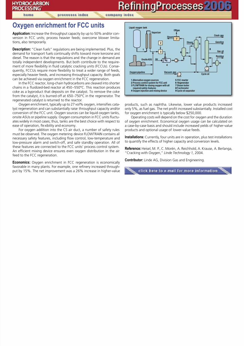
7/18/2019 Refining Processes Handbook 2006
http://slidepdf.com/reader/full/refining-processes-handbook-2006 179/222
tions, also temporarily.
Description: “Clean fuels” regulations are being implemented. Plus, thedemand for transport fuels continually shifts toward more kerosine anddiesel. The reason is that the regulations and the change in demand aretotally independent developments. But both contribute to the require-ment of more flexibility in fluid catalytic cracking units (FCCUs). Conse-quently, FCCUs require more flexibility to treat a wider range of feeds,especially heavier feeds, and increasing throughput capacity. Both goalscan be achieved via oxygen enrichment in the FCC regeneration.
In the FCC reactor, long-chain hydrocarbons are cleaved into shorterchains in a fluidized-bed reactor at 450 –550°C. This reaction produces
coke as a byproduct that deposits on the catalyst. To remove the cokefrom the catalyst, it is burned off at 650 –750°C in the regenerator. Theregenerated catalyst is returned to the reactor.
Oxygen enrichment, typically up to 27 vol% oxygen, intensifies cata-lyst regeneration and can substantially raise throughput capacity and/orconversion of the FCC unit. Oxygen sources can be liquid oxygen tanks,onsite ASUs or pipeline supply. Oxygen consumption in FCC units fluctu-ates widely in most cases; thus, tanks are the best choice with respect toease of operation, flexibility and economy.
For oxygen addition into the CS air duct, a number of safety rulesmust be observed. The oxygen metering device FLOWTRAIN contains allnecessary safety features, including flow control, low-temperature andlow-pressure alarm and switch-off, and safe standby operation. All ofthese features are connected to the FCC units’ process control system.An efficient mixing device ensures even oxygen distribution in the airfeed to the FCC regeneration.
Economics: Oxygen enrichment in FCC regeneration is economicallyfavorable in many plants. For example, one refinery increased through-
put by 15%. The net improvement was a 26% increase in higher-value
products, such as naphtha. Likewise, lower value products increasedonly 5%, as fuel gas. The net profit increased substantially. Installed costfor oxygen enrichment is typically below $250,000.
Operating costs will depend on the cost for oxygen and the durationof oxygen enrichment. Economical oxygen usage can be calculated ona case-by-case basis and should include increased yields of higher-value
products and optional usage of lower-value feeds.Installations: Currently, four units are in operation, plus test installationsto quantify the effects of higher capacity and conversion levels.
Reference: Heisel, M. P., C. Morén, A. Reichhold, A. Krause, A. Berlanga,“Cracking with Oxygen,” Linde Technology 1, 2004.
Contributor: Linde AG, Division Gas and Engineering.
�
� � �
�
�
Olefin etherificationApplication: New processing methods improve etherification of C4– C7
reactive olefins including light catalytic naphtha (LCN) with alcohol (e.g.,

7/18/2019 Refining Processes Handbook 2006
http://slidepdf.com/reader/full/refining-processes-handbook-2006 180/222
methanol and ethanol). The processes, RHT-MixedEthers, RHT-MTBE,RHT-ETBE, RHT-TAME and RHT-TAEE, use unique concepts to achieve the
maximum conversion without applying cumbersome catalyst in the col-umn. The processing economics provide improvements over other avail-able ether technologies currently available. The technology suite canbe applied to ethyl tertiary butyl ether (ETBE) production in which wetethanol can be used in place of dry ethanol. The drier can be eliminated,which is approximately half the cost for an etherification unit. The RHTethers processes can provide the highest conversion with unique mul-tiple equilibrium stages.
Description: The feed is water washed to remove basic compounds
that are poisons for the resin catalyst of the etherification reaction. TheC4 ethers—methyl tertiary butyl ether (MTBE)/ETBE), C5– tertiary amylmethyl ether (TAME/ tertiary amyl ethyl ether (TAEE) and C6 /C7 ethersare made in this process separately. The reaction is difficult; heavierethers conversion of the reactive olefins are equilibrium conversion ofabout 97% for MTBE and 70% for TAME and much lower for C6 /C7 ethers are expected.
Higher alcohols have similar effects (azeotrope hydrocarbon/alcoholrelationship decreases when using methanol over ethanol). The equilib-rium conversions and azeotrope effects for higher ethers are lower, as isexpected. After the hydrocarbon feed is washed, it is mixed with alcoholwith reactive olefin ratio control with alcohol.
The feed mixture is heated to reaction temperature (and mixed withrecycle stream (for MTBE/ETBE only) and is sent to the first reactor (1),where equilibrium conversion is done in the presence of sulfonated resincatalyst, e.g. Amberlyst 15 or 35 or equivalent from other vendors.
Major vaporization is detrimental to this reaction. Vapor-phase re-active olefins are not available for reaction. Additionally at higher tem-peratures, there is slight thermal degradation of the catalyst occurs. The
reactor effluent is sent to fractionator (debutanizer or depentanizer) to
separate the ether and heavy hydrocarbons from C4 or C5 hydrocarbons,which are taken as overhead. Single or multiple draw offs are taken fromthe fractionation column. In the fractionation column, unreacted olefins(C4 or C5) are sent to the finishing reactor (5). This stream normally doesnot require alcohol, since azeotrope levels are available. But, some ad-
ditional alcohol is added for the equilibrium-stage reaction. Dependingon the liquid withdrawn (number of side draws), the conversion can beenhanced to a higher level than via other conventional or unconven-tional processes.
By installing multiple reactors, it is possible to extinct the olefinswithin the raffinate. The cost of side draws and reactors can achievepay-off in 6 to 18 months by the higher catalyst cost as compared toother processes. This process could provide 97– 99.9% isobutene con-version in C4 feed (depending on the configuration) and 95 – 98+% ofisoamylenes in C5 stream.
�
�
Continued
The ether product is taken from the bottom, cooled and sent to thestorage. The raffinate is washed in extractor column (6) with and is sentto the OSBL. The water/alcohol mixture is sent to alcohol recovery col-umn (7) where the alcohol is recovered and recycled as feed.
For ETBE and TAEE, ethanol dehydration is required for most of theprocesses, whereas for RHT process, wet ethanol can be used providing
Olefin etherification, continued catalyst. Distillation is done at optimum conditions. Much lower steamconsumption for alcohol recovery. For example, the C5 feed case requiresless alcohol with RHT configuration (azeotropic alcohol is not required)and lowers lower steam consumption.
Economics:CAPEX ISBL, MM USD (US Gulf Coast 1Q06,
1,000-bpd ether product) 9.1Utilities Basis 1,000 bpd ether

7/18/2019 Refining Processes Handbook 2006
http://slidepdf.com/reader/full/refining-processes-handbook-2006 181/222
p p p gmaximum conversions. If need be, the TBA specification can be met byoptimum design with additional equipment providing high ETBE yield
and conversion. Cost of ethanol dehydration is much more than thepresent configuration for the RHT wet-ethanol process.
The total capital cost /economics is lower with conventional catalystusage, compared to other technologies, which use complicated struc-ture, require installing a manway (cumbersome) and require frequentlycatalyst changes outs.
The RHT ether processes can provide maximum conversion as com-pared to other technologies with better economics. No complicated orproprietary internals for the column including single source expensive
Utilities Basis ,000 bpd et ePower kWh 45.0Water, cooling m3 / h 250Steam MP, Kg / h 6,000
Basis: FCC Feed (about 15–20% isobutylene in C4 mixed stream)
Commercial units: Technology is ready for commercialization.
Licensor: Refining Hydrocarbon Technologies LLC.
Olefins recoveryApplication: Recover high-purity hydrogen (H2) and C2
+ liquid productsfrom refinery offgases using cryogenics.

7/18/2019 Refining Processes Handbook 2006
http://slidepdf.com/reader/full/refining-processes-handbook-2006 182/222
Description: Cryogenic separation of refinery offgases and purges con-
taining 10– 80% H2 and 15 – 40% hydrocarbon liquids such as ethylene,ethane, propylene, propane and butanes. Refinery offgases are option-ally compressed and then pretreated (1) to remove sulfur, carbon di-oxide ( CO2), H2 O and other trace impurities. Treated feed is partiallycondensed in an integrated multi-passage exchanger system (2) againstreturning products and refrigerant.
Separated liquids are sent to a demethanizer (3) for stabilizationwhile hydrogen is concentrated (4) to 90 – 95%+ purity by further cool-ing. Methane, other impurities, and unrecovered products are sent tofuel or optionally split into a synthetic natural gas (SNG) product and
low-Btu fuel. Refrigeration is provided by a closed-loop system (5). MixedC2
+ liquids from the demethanizer can be further fractionated (6) intofinished petrochemical feeds and products such as ethane, ethylene,propane and propylene.
Operating conditions: Feed capacities from 10 to 150+ million scfd. Feedpressures as low as 150 psig. Ethylene recoveries are greater than 95%,with higher recoveries of ethane and heavier components. Hydrogenrecoveries are better than 95% recovery.
Economics: Hydrogen is economically co-produced with liquid hydro-carbon products, especially ethylene and propylene, whose high valuecan subsidize the capital investment. High hydrocarbon liquid productsrecovery is achieved without the cost for feed compression and subse-quent feed expansion to fuel pressure. Power consumption is a functionof hydrocarbon quantities in the feed and feed pressure. High-purityhydrogen is produced without the investment for a “back-end” PSAsystem. Project costs can have less than a two-year simple payback.
Installations: Five operating refinery offgas cryogenic systems processing
FCC offgas, cat reformer offgas, hydrotreater purge gas, coker offgas
and refinery fuel gas. Several process and refrigeration schemes usedsince 1987 with the most recent plant startup in 2001.
Reference: US Patents 6,266,977 and 6,560,989.Trautmann, S. R. and R. A. Davis, “Refinery offgases—alternative
sources for ethylene recovery and integration,” AIChE Spring Meeting,New Orleans, March 14, 2002, Paper 102d.
Licensor: Air Products and Chemicals Inc.
�
�
�
Olefins—butenes extractive distillationApplication: Separation of pure C4 olefins from olefinic/paraffinic C4 mix-tures via extractive distillation using a selective solvent. BUTENEX is the
hd h l l h l fi f f d k

7/18/2019 Refining Processes Handbook 2006
http://slidepdf.com/reader/full/refining-processes-handbook-2006 183/222
Uhde technology to separate light olefins from various C4 feedstocks,which include ethylene cracker and FCC sources.
Description: In the extractive distillation (ED) process, a single-com-pound solvent, N-Formylmorpholine (NFM), or NFM in a mixture withfurther morpholine derivatives, alters the vapor pressure of the com-ponents being separated. The vapor pressure of the olefins is loweredmore than that of the less soluble paraffins. Paraffinic vapors leave thetop of the ED column, and solvent with olefins leaves the bottom of theED column.
The bottom product of the ED column is fed to the stripper toseparate pure olefins (mixtures) from the solvent. After intensive heat
exchange, the lean solvent is recycled to the ED column. The solvent,which can be either NFM or a mixture including NFM, perfectly satisfiesthe solvent properties needed for this process, including high selectivity,thermal stability and a suitable boiling point.
Economics:
Consumption per metric ton of FCC C4 fraction feedstock: Steam, t / t 0.5 – 0.8 Water, cooling (T = 10°C ), m3 / t 15.0 Electric power, kWh/t 25.0
Product purity: n - Butene content 99.+ wt.– % min. Solvent content 1 wt.– ppm max.
Installation: Two commercial plants for the recovery of n - butenes havebeen installed since 1998.
Licensor: Uhde GmbH.
�
Olefins—dehydrogenation of lightparaffins to olefinsApplication: The Uhde STeam Active Reforming (STAR) process produces

7/18/2019 Refining Processes Handbook 2006
http://slidepdf.com/reader/full/refining-processes-handbook-2006 184/222
Application: The Uhde STeam Active Reforming (STAR) process produces(a) propylene as feedstock for polypropylene, propylene oxide, cumene,
acrylonitrile or other propylene derivatives, and (b) butylenes as feed-stock for methyl tertiary butyl ether (MTBE), alkylate, isooctane, polybu-tylenes or other butylene derivatives.
Feed: Liquefied petroleum gas (LPG) from gas fields, gas condensatefields and refineries.
Product: Propylene (polymer- or chemical-grade); isobutylene; n-butylenes;high-purity hydrogen (H2) may also be produced as a byproduct.
Description: The fresh paraffin feedstock is combined with paraffin re-
cycle and internally generated steam. After preheating, the feed is sentto the reaction section. This section consists of an externally fired tubularfixed-bed reactor (Uhde reformer) connected in series with an adiabat-ic fixed-bed oxyreactor (secondary reformer type). In the reformer, theendothermic dehydrogenation reaction takes place over a proprietary,noble metal catalyst.
In the adiabatic oxyreactor, part of the hydrogen from the intermediateproduct leaving the reformer is selectively converted with added oxygenor air, thereby forming steam. This is followed by further dehydrogenation
over the same noble-metal catalyst. Exothermic selective H2 conversionin the oxyreactor increases olefin product space-time yield and suppliesheat for further endothermic dehydrogenation. The reaction takes placeat temperatures between 500– 600°C and at 4 – 6 bar.
The Uhde reformer is top-fired and has a proprietary “cold” out-let manifold system to enhance reliability. Heat recovery utilizes processheat for high-pressure steam generation, feed preheat and for heat re-quired in the fractionation section.
After cooling and condensate separation, the product is subse-quently compressed, light-ends are separated and the olefin product is
separated from unconverted paraffins in the fractionation section.
Apart from light-ends, which are internally used as fuel gas, theolefin is the only product. High-purity H2 may optionally be recoveredfrom light-ends in the gas separation section.
Economics: Typical specific consumption figures (for polymer-gradepropylene production) are shown (per metric ton of propylene product,
including production of oxygen and all steam required):Propane, kg/metric ton 1,200Fuel gas, GJ/metric ton 6.4Circul. cooling water, m3 /metric ton 170Electrical energy, kWh/metric ton 100
Installation: Two commercial plants using the STAR process for dehydro-genation of isobutane to isobutylene have been commissioned (in theUS and Argentina). More than 60 Uhde reformers and 25 Uhde second-ary reformers have been constructed worldwide.
�
Continued
References: Heinritz-Adrian, M., “Advanced technology for C3 /C4 dehy-drogenation, “ First Russian & CIS GasTechnology Conference, Moscow,Russia, September 2004.
Heinritz-Adrian, M., N. Thiagarajan, S. Wenzel and H. Gehrke,“STAR—Uhde’s dehydrogenation technology (an alternative route toC3- and C4-olefins),” ERTC Petrochemical 2003, Paris, France, March
Olefins, continued

7/18/2019 Refining Processes Handbook 2006
http://slidepdf.com/reader/full/refining-processes-handbook-2006 185/222
3 4
2003.Thiagarajan, N., U. Ranke and F. Ennenbach, “Propane/butane de-
hydrogenation by steam active reforming,” Achema 2000, Frankfurt,Germany, May 2000.
Licensor: Uhde GmbH.
Oligomerization—C3 /C4 cutsApplication: To dimerize light olefins such as ethylene, propylene andbutylenes using the Dimersol process. The main applications are:
Di i ti f l d i hi h t l b ili

7/18/2019 Refining Processes Handbook 2006
http://slidepdf.com/reader/full/refining-processes-handbook-2006 186/222
• Dimerization of propylene, producing a high-octane, low-boilingpoint gasoline called Dimate
• Dimerization of n-butylene producing C8 olefins for plasticizer syn-thesis.
The C3 feeds are generally the propylene cuts from catalytic crack-ing units. The C4 cut source is mainly the raffinate from butadiene andisobutylene extraction.
Description: Dimerization is achieved in the liquid phase at ambienttemperature by means of a soluble catalytic complex. One or severalreactors (1) in series are used. After elimination of catalyst (2, 3), theproducts are separated in an appropriate distillation section (4).
Product quality: For gasoline production, typical properties of the Di-mate are:
Specific gravity, @15°C 0.70End point, °C 20570% vaporized, °C 80Rvp, bar 0.5RONC 96MONC 81RON blending value, avg. 103
Economics: For a plant charging 100,000 tpy of C3 cut (% propylene)and producing 71,000 tpy of Dimate gasoline:
Investment for a 2002 ISBL Gulf Coast erected cost,excluding engineering fees, US $7 million
Utilities per ton of feedElectric power, kWh 10.8Steam, HP, t 0.14Water, cooling, t 28.5Catalyst + chemicals, US$ 9.3
Installation: Twenty-seven units have been built or are under construc-tion.
Reference: “Olefin oligomerization with homogeneous catalysis,” 1999Dewitt Petrochemical Conference, Houston.
Licensor: Axens.
�
�
�
�
Oligomerization—polynaphthaApplication: To produce C6+ isoolefin fractions that can be used as high-octane blending stocks for the gasoline pool and high-smoke-pointblending stocks for kerosine and jet fuel The Polynaphtha and electopol
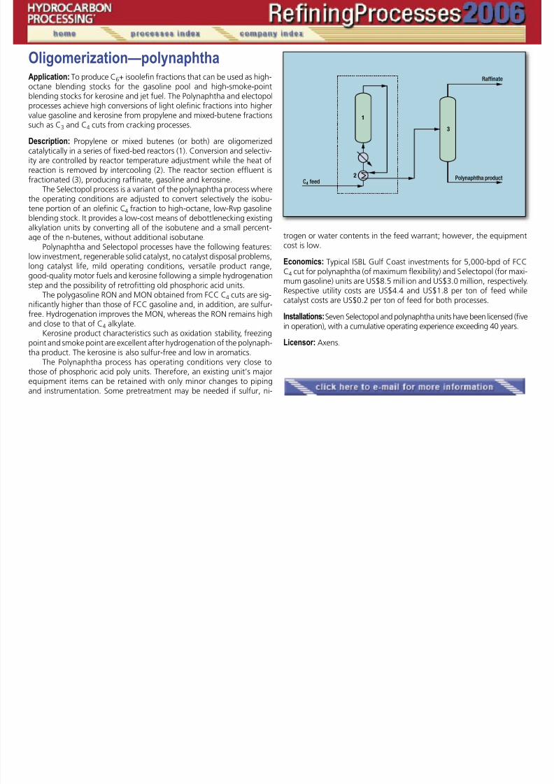
7/18/2019 Refining Processes Handbook 2006
http://slidepdf.com/reader/full/refining-processes-handbook-2006 187/222
blending stocks for kerosine and jet fuel. The Polynaphtha and electopolprocesses achieve high conversions of light olefinic fractions into higher
value gasoline and kerosine from propylene and mixed-butene fractionssuch as C3 and C4 cuts from cracking processes.
Description: Propylene or mixed butenes (or both) are oligomerizedcatalytically in a series of fixed-bed reactors (1). Conversion and selectiv-ity are controlled by reactor temperature adjustment while the heat ofreaction is removed by intercooling (2). The reactor section effluent isfractionated (3), producing raffinate, gasoline and kerosine.
The Selectopol process is a variant of the polynaphtha process wherethe operating conditions are adjusted to convert selectively the isobu-
tene portion of an olefinic C4 fraction to high-octane, low-Rvp gasolineblending stock. It provides a low-cost means of debottlenecking existingalkylation units by converting all of the isobutene and a small percent-age of the n-butenes, without additional isobutane.
Polynaphtha and Selectopol processes have the following features:low investment, regenerable solid catalyst, no catalyst disposal problems,long catalyst life, mild operating conditions, versatile product range,good-quality motor fuels and kerosine following a simple hydrogenationstep and the possibility of retrofitting old phosphoric acid units.
The polygasoline RON and MON obtained from FCC C4 cuts are sig-
nificantly higher than those of FCC gasoline and, in addition, are sulfur-free. Hydrogenation improves the MON, whereas the RON remains highand close to that of C4 alkylate.
Kerosine product characteristics such as oxidation stability, freezingpoint and smoke point are excellent after hydrogenation of the polynaph-tha product. The kerosine is also sulfur-free and low in aromatics.
The Polynaphtha process has operating conditions very close tothose of phosphoric acid poly units. Therefore, an existing unit’s majorequipment items can be retained with only minor changes to piping
and instrumentation. Some pretreatment may be needed if sulfur, ni-
trogen or water contents in the feed warrant; however, the equipmentcost is low.
Economics: Typical ISBL Gulf Coast investments for 5,000-bpd of FCCC4 cut for polynaphtha (of maximum flexibility) and Selectopol (for maxi-mum gasoline) units are US$8.5 mill ion and US$3.0 million, respectively.Respective utility costs are US$4.4 and US$1.8 per ton of feed while
catalyst costs are US$0.2 per ton of feed for both processes.
Installations: Seven Selectopol and polynaphtha units have been licensed (fivein operation), with a cumulative operating experience exceeding 40 years.
Licensor: Axens.
�
�

7/18/2019 Refining Processes Handbook 2006
http://slidepdf.com/reader/full/refining-processes-handbook-2006 188/222
Economics: Table 1 lists the benefits of the CrystPX process.
TABLE 1. Techno-economic comparison of CrystPX to conventionaltechnologies
Basis: 90% PX feed purity, 400,000 tpy of 99.9 wt% PX
CrystPX Other crystallization technologies
Paraxylene, continued

7/18/2019 Refining Processes Handbook 2006
http://slidepdf.com/reader/full/refining-processes-handbook-2006 189/222
Investment cost, $MM 26.0 40.0
Paraxylene recovery, % 95 95Electricity consumption, kWh/ ton PX 50 80
Operation mode Continuous Batch
Licensor: GTC Technology Inc.
Note: CrystPX is a proprietary process technology marketed and licensedby GTC Technology Inc., in alliance with Lyondell Chemical Co.
Prereforming with feedultra purificationApplication: Ultra-desulfurization and adiabatic-steam reforming of hy-

7/18/2019 Refining Processes Handbook 2006
http://slidepdf.com/reader/full/refining-processes-handbook-2006 190/222
pp g ydrocarbon feed from refinery offgas or natural gas through LPG to naph-
tha feeds as a prereforming step in the route to hydrogen production.
Description: Sulfur components contained in the hydrocarbon feed areconverted to H 2 S in the HDS vessel and then fed to two desulfurizationvessels in series. Each vessel contains two catalyst types—the first forbulk sulfur removal and the second for ultrapurification down to sulfurlevels of less than 1 ppb.
The two-desulfurization vessels are arranged in series in such a waythat either may be located in the lead position allowing online changeout of the catalysts. The novel interchanger between the two vessels
allows for the lead and lag vessels to work under different optimizedconditions for the duties that require two catalyst types. This arrange-ment may be retrofitted to existing units.
Desulfurized feed is then fed to a fixed bed of nickel-based catalystthat converts the hydrocarbon feed, in the presence of steam, to a prod-uct stream containing only methane together with H 2, CO, CO 2 andunreacted steam which is suitable for further processing in a conven-tional fired reformer. The CRG prereformer enables capital cost savingsin primary reforming due to reductions in the radiant box heat load. Italso allows high-activity gas-reforming catalyst to be used. The ability to
increase preheat temperatures and transfer radiant duty to the convec-tion section of the primary reformer can minimize involuntary steamproduction.
Operating conditions: The desulfurization section typically operates be-tween 170 ° C and 420 ° C and the CRG prereformer wil l operate over awide range of temperatures from 250 ° C to 650 ° C and at pressures upto 75 bara.
Installation: CRG process technology covers 40 years of experience withover 150 plants built and operated. Ongoing development of the cata-lyst has lead to almost 50 such units since 1990.
Catalyst: The CRG catalyst is manufactured under license by Johnson
Matthey Catalysts.
Licensor: The process and CRG catalyst are licensed by Davy ProcessTechnology.
�

7/18/2019 Refining Processes Handbook 2006
http://slidepdf.com/reader/full/refining-processes-handbook-2006 191/222
Refinery offgas—purificationand olefins recoveryApplication: Purification and recovery of olefins from FCC, RFCC and
�

7/18/2019 Refining Processes Handbook 2006
http://slidepdf.com/reader/full/refining-processes-handbook-2006 192/222
DCC offgas.
Products: Hydrogen, methane, ethylene and LPG.
Description: Refinery offgas streams (ROG) from fluid catalytic cracker(FCC) units, deep catalytic cracking (DCC) units, catalytic pyrolysis pro-cess (CPP) units and coker units are normally used as fuel gas in re-fineries. However, these streams contain significant amounts of olefins(ethylene and propylene), which can be economically recovered. In fact,many such streams can be recovered with project payout times of lessthan one year.
Offgas-recovery units can be integrated with existing olefins unitsor, if the flows are large enough, stand-alone units may be feasible.Offgas-recovery units can be broken down into sections including feedcontaminant removal, ethylene recovery and propylene recovery. Feedcontaminants including acid gases, O2, NOx, arsine, mercury, ammonia,nitrites, COS, acetylenes and water must be removed. It is critical thatthe designer of the unit be experienced with feedstock pretreatmentsince many of the trace components in the ROG streams can impact theultimate product purity, catalyst performance and operational safety.
The ethylene recovery section can be a stand-alone unit where ei-
ther dilute ethylene or polymer-grade ethylene (PGE) is produced; or aunit where partially recovered streams suitable for integration into anethylene plant recovery section are produced.
Integration of treated ROG into an ethylene plant involves compres-sion and treatment /removal of contaminants. If an ethylene product isrequired (dilute ethylene or PGE), an additional section is needed thatseparates hydrogen, nitrogen and methane in a cold box, followed by ademethanizer, a deethanizer; and for PGE and C2 splitter.
Removal of contaminants including acid gases, COS, RSH, NO2, NH3,HCN, H2O, AsH3 and Hg is achieved by established processing methods,
depending on the concentrations in the ROG feed. The difficult con-
taminants to remove in the ROG are the O2 and NOx, which are typicallyremoved by hydrogenation to H2O and NH3. Commercially available hy-drogenation catalysts cause significant loss of ethylene to ethane. BASF
together with Shaw have developed a copper-based catalyst (R3-81),which in sulfided form is capable of complete hydrogenation of the O2 and NOx.
Deoxo reactor. The Deoxo Reactor, in which the sulfided-copper catalyst(R3-81) is used, serves a dual function. By removing the O 2, NOx andacetylene, it provides necessary purification of olefins but is also vitaltoward the safety of the process. Without it, the formation of explosivedeposits in and around the cold box can become an issue. An additional,
�
�
�
�
�
�
�
Continued
economic benefit of the Shaw Stone & Webster solution, comes fromthe superior selectivity of the special catalyst— allowing deep removal ofO2 and NOx, with negligible ethylene loss.
Installation: Three units are currently operating. Several units are underconstruction, and many units are under design.
Refinery offgas—purification and olefins recovery,continued

7/18/2019 Refining Processes Handbook 2006
http://slidepdf.com/reader/full/refining-processes-handbook-2006 193/222
Licensor: Shaw Stone & Webster Inc.
Resid catalytic crackingApplication: Selective conversion of gasoil and heavy residual feed-stocks.
Products: Hi h t li di till t d C C l fi

7/18/2019 Refining Processes Handbook 2006
http://slidepdf.com/reader/full/refining-processes-handbook-2006 194/222
Products: High-octane gasoline, distillate and C3– C4 olefins.
Description: For residue cracking the process is known as R2R (reactor–2 re-generators). Catalytic and selective cracking occurs in a short-contact-timeriser where oil feed is effectively dispersed and vaporized through a propri-etary feed-injection system. Operation is carried out at a temperature con-sistent with targeted yields. The riser temperature profile can be optimizedwith the proprietary mixed temperature control (MTC) system.
Reaction products exit the riser-reactor through a high-efficiency,close-coupled, proprietary riser termination device RSS (riser separatorstripper). Spent catalyst is pre-stripped followed by an advanced high-ef-ficiency packed stripper prior to regeneration. The reaction product va-por may be quenched to give the lowest dry gas and maximum gasolineyield. Final recovery of catalyst particles occurs in cyclones before theproduct vapor is transferred to the fractionation section.
Catalyst regeneration is carried out in two independent stagesequipped with proprietary air and catalyst distribution systems resultingin fully regenerated catalyst with minimum hydrothermal deactivation,plus superior metals tolerance relative to single-stage systems. Thesebenefits are derived by operating the first-stage regenerator in a partial-burn mode, the second-stage regenerator in a full-combustion mode
and both regenerators in parallel with respect to air and flue gas flows.The resulting system is capable of processing feeds up to about 6 wt%ConC without additional catalyst cooling means, with less air, lower cat-alyst deactivation and smaller regenerators than a single-stage regen-erator design. Heat removal for heavier feedstocks (above 6 CCR) maybe accomplished by using a reliable dense-phase catalyst cooler, whichhas been commercially proven in over 56 units.
The converter vessels use a cold-wall design that results in mini-mum capital investment and maximum mechanical reliability and safety.Reliable operation is ensured through the use of advanced fluidization
technology combined with a proprietary reaction system. Unit design
is tailored to refiner’s needs and can include wide turndown flexibility.Available options include power recovery, wasteheat recovery, flue-gastreatment and slurry filtration.
Existing gas oil units can be easily retrofitted to this technology. Re-vamps incorporating proprietary feed injection and riser termination de-
vices and vapor quench result in substantial improvements in capacity,yields and feedstock flexibility within the mechanical limits of the exist-ing unit.
Installation: Shaw Stone & Webster and Axens have licensed 27 full-technology R2R units and performed more than 150 revamp projects.
Reference: Meyers, R., Handbook of Petroleum Refining Process, Third Ed.
Licensor: Shaw Stone & Webster and Axens, IFP Group Technologies.
Slack wax deoilingApplication: Process to produce high-melting and low-oil containinghard wax products for a wide range of applications.

7/18/2019 Refining Processes Handbook 2006
http://slidepdf.com/reader/full/refining-processes-handbook-2006 195/222
Feeds: Different types of slack waxes from lube dewaxing units, includ-
ing macrocrystalline (paraffinic) and microcrystalline wax (from residualoil). Oil contents typically range from 5–25 wt%.
Products: Wax products with an oil content of less than 0.5 wt%, exceptfor the microcrystalline paraffins, which may have a somewhat higheroil content. The deoiled wax can be processed further to produce high-quality, food-grade wax.
Description: Warm slack wax is dissolved in a mixture of solvents andcooled by heat exchange with cold main filtrate. Cold wash filtrate
is added to the mixture, which is chilled to filtration temperature inscraped-type coolers. Crystallized wax is separated from the solution ina rotary drum filter (stage 1). The main filtrate is pumped to the soft-waxsolvent recovery section. Oil is removed from the wax cake in the filterby thorough washing with chilled solvent.
The wax cake of the first filter stage consists mainly of hard wax andsolvent but still contains some oil and soft wax. Therefore, it is blown offthe filter surface and is again mixed with solvent and repulped in an agi-tated vessel. From there the slurry is fed to the filter stage 2 and the waxcake is washed again with oil-free solvent. The solvent containing hard
wax is pumped to a solvent recovery system. The filtrate streams of filterstage 2 are returned to the process, the main filtrate as initial dilution tothe crystallization section, and the wash filtrate as repulp solvent.
The solvent recovery sections serve to separate solvent from thehard wax respectively from the soft wax. These sections yield oil-freehard wax and soft wax (or foots oil).
Utility requirements (slack wax feed containing 20 wt% oil, per metricton of feed):
Steam, LP, kg 1,500 Water, cooling, m3 120
Electricity, kWh 250
Installation: Wax deoiling units have been added to existing solvent de-waxing units in several lube refineries. The most recent reference in-cludes the revamp of a dewaxing unit into two-stage wax deoiling; thisunit went onstream in 2005.
Licensor: Uhde GmbH.
�
�
�
SO2 removal, regenerativeApplication: Regenerative scrubbing system to recover SO2 from flue gascontaining high SO2 levels such as gas from FCC regenerator or inciner-ated SRU tail gas and other high SO2 applications. The LABSORB process

7/18/2019 Refining Processes Handbook 2006
http://slidepdf.com/reader/full/refining-processes-handbook-2006 196/222
ated SRU tail gas and other high SO2 applications. The LABSORB processis a low pressure drop system and is able to operate under varying condi-
tions and not sensitive to variations in the upstream processes.
Products: The product from the LABSORB process is a concentrated SO2
stream consisting of approximately 90% SO2 and 10% moisture. Thisstream can be sent to the front of the SRU to be mixed with H2S andform sulfur, or it can be concentrated for other marketable uses.
Description: Hot dirty flue gas is cooled in a flue-gas cooler or waste-heat recovery boiler prior to entering the systems. Steam produced canbe used in the LABSORB plant. The gas is then quenched to adiabatic
saturation (typically 50°C–75°C) in a quencher/pre-scrubber; it proceedsto the absorption tower where the SO2 is removed from the gas. Thetower incorporates multiple internal and re-circulation stages to ensuresufficient absorption.
A safe, chemically stable and regenerable buffer solution is con-tacted with the SO2-rich gas for absorption. The rich solution is thenpiped to a LABSORB buffer regeneration section where the solution isregenerated for re-use in the scrubber. Regeneration is achieved usinglow-pressure steam and conventional equipment such as strippers, con-densers and heat exchangers.
Economics: This process is very attractive at higher SO2 concentrationsor when liquid or solid effluents are not allowed. The system’s bufferloss is very low, contributing to a very low operating cost. Additionally,when utilizing LABSORB as an SRU tail-gas treater, many componentsnormally associated with the SCOT process are not required; thus savingconsiderable capital.
Installations: One SRU tail-gas system and two FCCU scrubbing systems.
Reference: Confuorto, Weaver and Pedersen, “LABSORB regenerative
scrubbing operating history, design and economics,” Sulfur 2000, SanFrancisco, October 2000.
Confuorto, Eagleson and Pedersen, “LABSORB, A regenerable wetscrubbing process for controlling SO2 emissions,” Petrotech-2001, NewDelhi, January 2001.
Licensor: Belco Technologies Corp.
�
Sour gas treatmentApplication: The WSA process (Wet gas Sulfuric Acid) treats all types ofsulfur-containing gases such as amine and Rectisol regenerator offgas,SWS gas and Claus plant tail gas in refineries, gas treatment plants,
�
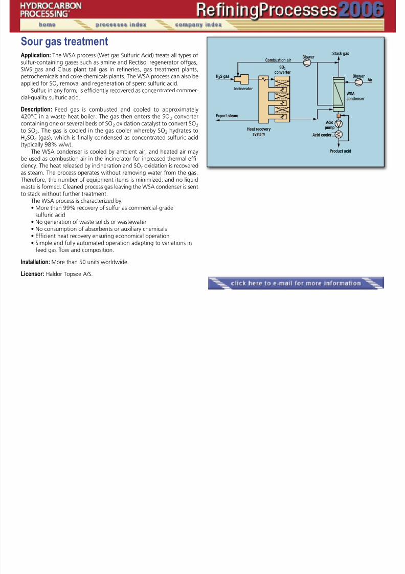
7/18/2019 Refining Processes Handbook 2006
http://slidepdf.com/reader/full/refining-processes-handbook-2006 197/222
petrochemicals and coke chemicals plants. The WSA process can also be
applied for SOx removal and regeneration of spent sulfuric acid.Sulfur, in any form, is efficiently recovered as concentrated commer-
cial-quality sulfuric acid.
Description: Feed gas is combusted and cooled to approximately420°C in a waste heat boiler. The gas then enters the SO2 convertercontaining one or several beds of SO2 oxidation catalyst to convert SO2 to SO3. The gas is cooled in the gas cooler whereby SO3 hydrates toH2SO4 (gas), which is finally condensed as concentrated sulfuric acid(typically 98% w/w).
The WSA condenser is cooled by ambient air, and heated air maybe used as combustion air in the incinerator for increased thermal effi-ciency. The heat released by incineration and SO2 oxidation is recoveredas steam. The process operates without removing water from the gas.Therefore, the number of equipment items is minimized, and no liquidwaste is formed. Cleaned process gas leaving the WSA condenser is sentto stack without further treatment.
The WSA process is characterized by:• More than 99% recovery of sulfur as commercial-grade
sulfuric acid
• No generation of waste solids or wastewater• No consumption of absorbents or auxiliary chemicals• Efficient heat recovery ensuring economical operation• Simple and fully automated operation adapting to variations in
feed gas flow and composition.
Installation: More than 50 units worldwide.
Licensor: Haldor Topsøe A/S.
�
Spent acid regenerationApplication: The WSA process (Wet gas Sulfuric Acid) treats spent sul-furic acid from alkylation as well as other types of waste sulfuric acidin the petrochemical and chemicals industry. Amine regenerator offgas

7/18/2019 Refining Processes Handbook 2006
http://slidepdf.com/reader/full/refining-processes-handbook-2006 198/222
and /or refinery gas may be used as auxiliary fuel. The regenerated acid
will contain min. 98% H2SO4 and can be recycled directly to the alkyla-tion process.
The WSA process is also applied for conversion of H2S and removalof SOx.
Description: Spent acid is decomposed to SO2 and water vapor in anincinerator using amine regenerator offgas or refinery gas as fuel. TheSO2 containing flue gas is cooled in a waste-heat boiler and solid matteroriginating from the acid feed is separated in an electrostatic precipita-tor. By adding preheated air, the process gas temperature and oxygen
content are adjusted before the catalytic converter converting SO2 toSO3. The gas is cooled in the gas cooler whereby SO3 is hydrated toH2SO4 (gas), which is finally condensed as 98% sulfuric acid.
The WSA condenser is cooled by ambient air. The heated air may beused as combustion air in the burner for increased thermal efficiency. Theheat released by incineration and SO2 oxidation is recovered as steam.
The process operates without removing water from the gas. There-fore, the number of equipment items is minimized and no liquid wasteis formed. This is especially important in spent acid regeneration whereSO3 formed by the acid decomposition will otherwise be lost with thewastewater.
The WSA process is characterized by:• No generation of waste solids or wastewater• No consumption of absorbents or auxiliary chemicals• Efficient heat recovery ensuring economical operation• Simple and fully automated operation adapting to variations in
feed flow and composition.
Installation: More than 50 WSA units worldwide, including 7 for spentacid regeneration.
Licensor: Haldor Topsøe A/S.
�

7/18/2019 Refining Processes Handbook 2006
http://slidepdf.com/reader/full/refining-processes-handbook-2006 199/222

7/18/2019 Refining Processes Handbook 2006
http://slidepdf.com/reader/full/refining-processes-handbook-2006 200/222
Sulfur processingApplication: The D’GAASS Sulfur Degassing Process removes dissolvedH2S and H2Sx from produced liquid sulfur. Undegassed sulfur can createodor problems and poses toxic and explosive hazards during the storage
d f li id lf
�

7/18/2019 Refining Processes Handbook 2006
http://slidepdf.com/reader/full/refining-processes-handbook-2006 201/222
and transport of liquid sulfur.
Description: Degasification is accomplished in a pressurized vertical ves-sel where undegassed sulfur is efficiently contacted with pressurizedprocess air (instrument or clean utility air). The contactor vessel may belocated at any convenient location. The undegassed sulfur is pumped tothe vessel and intimately contacted with air across special fixed vesselinternals.
Operation at elevated pressure and a controlled temperature ac-celerates the oxidation of H2S and polysulfides (H2Sx) to sulfur. The de-gassed sulfur can be sent to storage or directly to loading without ad-
ditional pumping. Operation at elevated pressure allows the overheadvapor stream to be routed to the traditional incinerator location, or tothe SRU main burner or TGTU line burner—thus eliminating the degas-sing unit as an SO2 emission source.
Economics: D’GAASS achieves 10 ppmw combined H2S/H2Sx in productsulfur without using catalyst. Elevated pressure results in the followingbenefits: low capital investment, very small footprint, low operating costand low air requirement. Operation is simple, requiring minimal opera-tor and maintenance time. No chemicals, catalysts, etc., are required.
Installations: Twenty-one D’GAASS units in operation. Twenty-six ad-ditional trains in engineering and construction phase with total capacityover 25,000 long ton per day (LTPD).
Reference: US Patent 5,632,967.Nasato, E. and T. A. Allison, “Sulfur degasification—The D’GAASS
process,” Laurance Reid Gas Conditioning Conference, Norman, Okla-homa, March, 1998.
Fenderson, S., “Continued development of the D’GAASS sulfur de-
gasification process,” Brimstone Sulfur Recovery Symposium, Canmore,Alberta, May 2001.
Licensor: Goar, Allison & Associates, Inc.
Sulfur recoveryApplication: The COPE Oxygen Enrichment Process allows existing Claussulfur recovery/tail gas cleanup units to increase capacity and recov-ery, can provide redundant sulfur processing capacity, and can improve
b ti f f it i l id
��
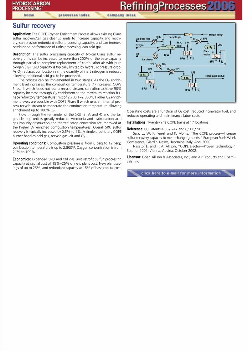
7/18/2019 Refining Processes Handbook 2006
http://slidepdf.com/reader/full/refining-processes-handbook-2006 202/222
combustion performance of units processing lean acid gas.
Description: The sulfur processing capacity of typical Claus sulfur re-covery units can be increased to more than 200% of the base capacitythrough partial to complete replacement of combustion air with pureoxygen (O2). SRU capacity is typically limited by hydraulic pressure drop.As O2 replaces combustion air, the quantity of inert nitrogen is reducedallowing additional acid gas to be processed.
The process can be implemented in two stages. As the O2 enrich-ment level increases, the combustion temperature (1) increases. COPEPhase I, which does not use a recycle stream, can often achieve 50%
capacity increase through O2 enrichment to the maximum reaction fur-nace refractory temperature limit of 2,700ºF – 2,800ºF. Higher O2 enrich-ment levels are possible with COPE Phase II which uses an internal pro-cess recycle stream to moderate the combustion temperature allowingenrichment up to 100% O2.
Flow through the remainder of the SRU (2, 3, and 4) and the tailgas cleanup unit is greatly reduced. Ammonia and hydrocarbon acidgas impurity destruction and thermal stage conversion are improved atthe higher O2 enriched combustion temperatures. Overall SRU sulfurrecovery is typically increased by 0.5% to 1%. A single proprietary COPE
burner handles acid gas, recycle gas, air and O2.
Operating conditions: Combustion pressure is from 6 psig to 12 psig;combustion temperature is up to 2,800ºF. Oxygen concentration is from21% to 100%.
Economics: Expanded SRU and tail gas unit retrofit sulfur processingcapacity at capital cost of 15% – 25% of new plant cost. New plant sav-ings of up to 25%, and redundant capacity at 15% of base capital cost.
Operating costs are a function of O2 cost, reduced incinerator fuel, andreduced operating and maintenance labor costs.
Installations: Twenty-nine COPE trains at 17 locations.
Reference: US Patents 4,552,747 and 6,508,998.
Sala, L., W. P. Ferrell and P. Morris, “The COPE process—Increasesulfur recovery capacity to meet changing needs,” European Fuels WeekConference, Giardini Naxos, Taormina, Italy, April 2000.
Nasato, E. and T. A. Allison, “COPE Ejector—Proven technology,”Sulphur 2002, Vienna, Austria, October 2002.
Licensor: Goar, Allison & Associates, Inc., and Air Products and Chemi-cals, Inc.
�

7/18/2019 Refining Processes Handbook 2006
http://slidepdf.com/reader/full/refining-processes-handbook-2006 203/222
Treating—jet fuel/kerosineApplication: NAPFINING / MERICAT II / AQUAFINING systems eliminatenaphthenic acids and mercaptans from kerosine to meet acid numberand mercaptan jet fuel specifications. Caustic, air and catalyst are usedalong with FIBER FILM Contactor technology and an upflow catalyst im
�

7/18/2019 Refining Processes Handbook 2006
http://slidepdf.com/reader/full/refining-processes-handbook-2006 204/222
along with FIBER-FILM Contactor technology and an upflow catalyst im-
pregnated carbon bed saturated with caustic.
Description: In the NAPFINING system, the caustic phase flows alongthe fibers of the FIBER-FILM Contactor as it preferentially wets the fi-bers. The kerosine phase simultaneously flows through the caustic-wet-ted fibers where naphthenic acids react with the caustic phase to formsodium naphthenate. The two phases disengage and the naphthenicacid-free kerosine flows to the MERICAT II where the mercaptans reactwith caustic, air, and catalyst in the FIBER-FILM Contactor to form disul-fides. The two phases disengage again and the kerosine flows upwards
through a catalyst impregnated carbon bed where the remaining heavymercaptans are converted to disulfides.
An AQUAFINING system is then used to water wash the kerosinedownstream of the MERICAT II vessel to remove sodium. Salt driers andclay filters are used downstream of the water wash to remove water,surfactants and particulates to ensure a completely clean product.
Competitive advantages: FIBER-FILM Contactor technology requiressmaller processing vessels thus saving valuable plant space and reduc-ing capital expenditure. Onstream factor is 100% whereas electrostatic
precipitators and downflow fixed-bed reactors onstream factors are un-predictable.
Installation: One hundred seventy-five installations worldwide.
References: Hydrocarbon Technology International, 1993.Petroleum Technology Quarterly, Winter 1996/97.
Licensor: Merichem Chemicals & Refinery Services LLC.
Treating—gasesApplication: AMINEX and THIOLEX systems extract H2S from gases withamine or caustic solution using FIBER-FILM Contactor technology.
Description: In an AMINEX system, the amine phase flows along the fi-

7/18/2019 Refining Processes Handbook 2006
http://slidepdf.com/reader/full/refining-processes-handbook-2006 205/222
Description: In an AMINEX system, the amine phase flows along the fibers of the FIBER-FILM Contactor as it preferentially wets the fibers. Thegas phase flows through the Contactor parallel to the amine-wettedfibers as the H2S is extracted into the amine. The two phases disengagein the separator vessel with the rich amine flowing to the amine regen-eration unit and the treated gas flowing to its final use.
Similarly, a THIOLEX system employs the same process utilizing caus-tic to preferentially wet the fibers as the H2S is extracted into the causticphase. The rich caustic flows to sulfidic caustic storage and the treatedgas flows to its final use.
Competitive advantages: FIBER-FILM Contactor technology requires
smaller processing vessels thus saving valuable plant space and reducingcapital expenditures.
Installation: Four installations worldwide in THIOLEX service.
Reference: Hydrocarbon Processing, Vol. 63, No. 4, April 1984, P. 87.
Licensor: Merichem Chemicals & Refinery Services LLC.
�
Treating— gasoline and LPGApplication: THIOLEX/REGEN systems extract H2S and mercaptans fromgases and light liquid hydrocarbon streams, including gasolines, withcaustic using FIBER-FILM Contactor technology. It can also be used tohydrolyze and remove COS from LPG and propane

7/18/2019 Refining Processes Handbook 2006
http://slidepdf.com/reader/full/refining-processes-handbook-2006 206/222
hydrolyze and remove COS from LPG and propane.
Description: In a THIOLEX system, the caustic phase flows along thefibers of the FIBER-FILM Contactor as it preferentially wets the fibers.Hydrocarbon flows through the caustic-wetted fibers where the H2S andmercaptans are extracted into the caustic phase. The two phases disen-gage and the caustic flows to the REGEN where the caustic is regener-ated using heat, air and catalyst. The disulfide oil formed in this reactionmay be removed via gravity separation, FIBER-FILM solvent washing ora combination of the two. The regenerated caustic flows back to theTHIOLEX system for continued re-use.
COS is removed from LPG or propane by either employing AMINEXtechnology using an amine solution or THIOLEX technology using anMEA/caustic solution to hydrolyze the COS to H2S and CO2 which areeasily removed by amine or caustic.
Competitive advantages: FIBER-FILM Contactor technology requiressmaller processing vessels thus saving valuable plant space and reducingcapital expenditures.
Installation: At present, 350 installations worldwide.
References: Oil & Gas Journal, August 12, 1985, p. 78.Hydrocarbon Engineering, February 2000.
Licensor: Merichem Chemicals & Refinery Services LLC.
�
Treating—gasoline desulfurization,ultra deepApplication: EXOMER extracts recombinant mercaptan sulfur from se-lectively hydrotreated FCC gasoline streams with a proprietary treating
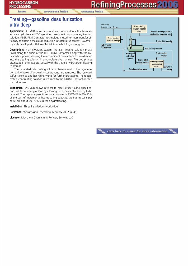
7/18/2019 Refining Processes Handbook 2006
http://slidepdf.com/reader/full/refining-processes-handbook-2006 207/222
y y g p p y gsolution. FIBER-FILM Contactor technology is used for mass transfer ef-ficiency to obtain a maximum reduction in total sulfur content. EXOMERis jointly developed with ExxonMobil Research & Engineering Co.
Description: In an EXOMER system, the lean treating solution phaseflows along the fibers of the FIBER-FILM Contactor along with the hy-drocarbon phase, allowing the recombinant mercaptans to be extractedinto the treating solution in a non-dispersive manner. The two phasesdisengage in the separator vessel with the treated hydrocarbon flowingto storage.
The separated rich treating solution phase is sent to the regenera-tion unit where sulfur-bearing components are removed. The removedsulfur is sent to another refinery unit for further processing. The regen-erated lean treating solution is returned to the EXOMER extraction stepfor further use.
Economics: EXOMER allows refiners to meet stricter sulfur specifica-tions while preserving octane by allowing the hydrotreater severity to bereduced. The capital expenditure for a grass roots EXOMER is 35 – 50%of the cost of incremental hydrotreating capacity. Operating costs perbarrel are about 60 –70% less than hydrotreating.
Installation: Three installations worldwide.
Reference: Hydrocarbon Processing, February 2002, p. 45.
Licensor: Merichem Chemicals & Refinery Services LLC.
�
Treating— gasoline sweeteningApplication: MERICAT systems oxidize mercaptans to disulfides by react-ing mercaptans with air and caustic in the presence of catalyst usingFIBER-FILM Contactor technology.

7/18/2019 Refining Processes Handbook 2006
http://slidepdf.com/reader/full/refining-processes-handbook-2006 208/222
Description: In a MERICAT system, the caustic phase flows along the fi-bers of the FIBER-FILM Contactor as it preferentially wets the fibers. Priorto entering the FIBER-FILM Contactor the gasoline phase mixes with airthrough a proprietary air sparger. The gasoline then flows through thecaustic-wetted fibers in the Contactor where the mercaptans are ex-tracted and converted to disulfides in the caustic phase. The disulfidesare immediately absorbed back into the gasoline phase. The two phasesdisengage and the caustic is recycled back to the FIBER-FILM Contactoruntil spent.
Competitive advantages: FIBER-FILM Contactor technology uses smallerprocessing vessels while guaranteeing the sodium content of the prod-uct. This saves valuable plant space and reduces capital expenditure.
Installation: At present, 135 installations worldwide.
Licensor: Merichem Chemicals & Refinery Services LLC.
�

7/18/2019 Refining Processes Handbook 2006
http://slidepdf.com/reader/full/refining-processes-handbook-2006 209/222
Treating—phenolic causticApplication: ECOMERICAT removes phenols from phenolic caustics byneutralization in conjunction with solvent washing using a FIBER-FILMContactor.

7/18/2019 Refining Processes Handbook 2006
http://slidepdf.com/reader/full/refining-processes-handbook-2006 210/222
Description: An ECOMERICAT system contacts the spent caustic with aslipstream of sweetened gasoline containing CO2 whereby neutralizingthe spent caustic, springing the phenols, absorbing the phenols intothe sweetened gasoline yielding neutral brine with minimal phenoliccontent.
Competitive advantages: • Minimizes spent caustic disposal cost• Reduces the phenol content of spent caustic and increases the
phenol content of sweetened gasoline thus adding value• Operates over a wide pH range• Simple to operate• No corrosion problems due to the buffering effect of CO2.
Installation: One installation worldwide.
Licensor: Merichem Chemicals & Refinery Services LLC.
�
Treating—Pressure swing adsorptionApplication: Pressure swing adsorption (PSA) process selectively adsorb-ing impurities from product streams. The impurities are adsorbed in afixed-bed adsorber at high pressure and desorbed by “swinging” theadsorber from the feed to the tail gas pressure and by using a high-pu-
�

7/18/2019 Refining Processes Handbook 2006
http://slidepdf.com/reader/full/refining-processes-handbook-2006 211/222
adsorber from the feed to the tail gas pressure and by using a high pu
rity purge. The desired component is not adsorbed and is recovered athigh purity.
Description: A PSA system operates as a batch process. However, mul-tiple adsorbers operating in a staggered sequence are used to produceconstant feed, product and tail gas flows.
Step 1: Adsorption. The feed gas enters an adsorber at a high pres-sure, impurities are adsorbed and high-purity product is produced. Flowis normally in the upwardly direction. When an adsorber has reachedits adsorption capacity, it is taken offline, and the feed automatically
switched to a fresh adsorber.Step 2: Co-current depressurization. To recover the product trapped
in the adsorbent void spaces, the adsorber is co-currently (in the direc-tion of feed flow) depressurized. The product gas withdrawn is usedinternally to repressurize and purge other adsorbers.
Step 3: Counter-current depressurization. At the end of the co-cur-rent depressurization step, the adsorbent is partially regenerated bycounter-currently depressurizing the adsorber to the tail-gas pressure,and thereby rejecting the impurities.
Step 4: Purge. The adsorbent is purged with a high-purity stream(taken from another adsorber on the cocurrent depressurization step) ata constant pressure to further regenerate the bed.
Step 5: Repressurization. The repressurization gas is provided fromthe co-current depressurization step and a slipstream from the product.When the adsorber has reached the adsorption pressure, the cycle hasbeen completed. The vessel is ready for the next adsorption cycle.
UOP’s polybed PSA system offers:• High reliability (greater than 99.8% onstream time)• Minimal manpower requirements due to automatic operation• Reduced equipment costs and enhanced performance based on
high performance
• Adsorbents and advanced PSA cycles• Lower operating and equipment costs for downstream process
units• Flexibility to process more than one feedstock• Minimal feed pretreatment and utility requirements• Adsorbents last for the life of the mechanical equipment (more
than 30 years).
�
�
Continued
Installation: Since commercialization in 1966, UOP has provided over700 PSA systems in more than 60 countries in the refining, petrochemi-cal, polymer, steel and power-generation industries. The Polybed PSAsystem has demonstrated exceptional economic value in many appli-cations, such as hydrogen recovery from refinery off-gases, monomerrecovery monomers in polyolefin plants, hydrogen extraction from gas-ification syngas, helium purification for industrial gas use, adjustmentof synthesis gas for ammonia production methane purification for pet-
Treating—pressure swing adsorption, continued

7/18/2019 Refining Processes Handbook 2006
http://slidepdf.com/reader/full/refining-processes-handbook-2006 212/222
of synthesis gas for ammonia production, methane purification for pet
rochemicals production, and H2 /CO ratio adjustment for syngas used inthe manufacture of oxo-alcohols. Feed conditions typically range from(7–70 kg/cm2g) (100 to 1,000 psig), with concentrations of the desiredcomponent from 30 – 98+ mol %. System capacities range from less than1 to more than 350 MMscfd (less than 1,100 to more than 390,000Nm3 /h).
Licensor: UOP LLC.

7/18/2019 Refining Processes Handbook 2006
http://slidepdf.com/reader/full/refining-processes-handbook-2006 213/222

7/18/2019 Refining Processes Handbook 2006
http://slidepdf.com/reader/full/refining-processes-handbook-2006 214/222

7/18/2019 Refining Processes Handbook 2006
http://slidepdf.com/reader/full/refining-processes-handbook-2006 215/222
Vacuum distillationApplication: Process to produce vacuum distillates that are suitable forlubricating oil production by downstream units, and as feedstocks toFCC and hydrocracker units.
�

7/18/2019 Refining Processes Handbook 2006
http://slidepdf.com/reader/full/refining-processes-handbook-2006 216/222
Feed: Atmospheric bottoms from crude oils (atmospheric residue) orhydrocracker bottoms.
Product: Vacuum distillates of precisely defined viscosities and flash points(for lube production) and low metals content (for FCC and hydrocrackerunits) as well as vacuum residue with specified softening point, penetra-tion and flash point.
Description: Feed is preheated in a heat-exchanger train and fed to thefired heater. The heater outlet temperature is controlled to produce therequired quality of vacuum distillates and residue. Structured packingsare typically used as tower internals to achieve low flashzone pressureand, hence, to maximize distillate yields. Circulating reflux streams en-able maximum heat recovery and reduced column diameter.
A wash section immediately above the flash zone ensures that themetals content in the lowest side draw is minimized. Heavy distillatefrom the wash trays is recycled to the heater inlet or withdrawn as met-als cut.
When processing naphthenic residues, a neutralization section maybe added to the fractionator.
Utility requirements (typical, North Sea Crude), units per m³ of feed:
Electricity, kWh 5Steam, MP, kg 15
Steam production, LP, kg 60Fuel oil, kg 7Water, cooling, m³ 3
Installation: Numerous installations using the Uhde (Edeleanu) propri-etary technology are in operation worldwide. The most recent referenceis a 86,000-bpd unit for a German refinery, which was commissionedin 2004; the unit produces vacuum distillates as feedstock for FCC andhydrocracker units.
Licensor: Uhde GmbH.
�
�
�
�
VisbreakingApplication: Manufacture incremental gas and distillate products and simul-taneously reduce fuel oil viscosity and pour point. Also, reduce the amountof cutter stock required to dilute the resid to meet the fuel oil specifications.Foster Wheeler/UOP offer both “coil” and “soaker” type visbreaking pro-
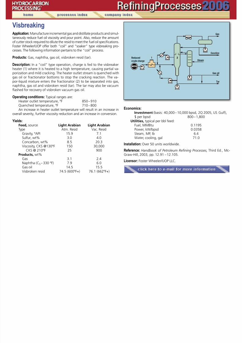
7/18/2019 Refining Processes Handbook 2006
http://slidepdf.com/reader/full/refining-processes-handbook-2006 217/222
cesses. The following information pertains to the “coil” process.
Products: Gas, naphtha, gas oil, visbroken resid (tar).
Description: In a “coil” type operation, charge is fed to the visbreakerheater (1) where it is heated to a high temperature, causing partial va-porization and mild cracking. The heater outlet stream is quenched withgas oil or fractionator bottoms to stop the cracking reaction. The va-por-liquid mixture enters the fractionator (2) to be separated into gas,naphtha, gas oil and visbroken resid (tar). The tar may also be vacuumflashed for recovery of visbroken vacuum gas oil.
Operating conditions: Typical ranges are:Heater outlet temperature, ºF 850 – 910Quenched temperature, ºF 710 – 800An increase in heater outlet temperature will result in an increase in
overall severity, further viscosity reduction and an increase in conversion.
Yields:Feed, source Light Arabian Light ArabianType Atm. Resid Vac. Resid
Gravity, ºAPI 15.9 7.1 Sulfur, wt% 3.0 4.0 Concarbon, wt% 8.5 20.3 Viscosity, CKS @130ºF 150 30,000 CKS @ 210ºF 25 900Products, wt% Gas 3.1 2.4 Naphtha (C5 – 330 ºF) 7.9 6.0 Gas oil 14.5 15.5
Visbroken resid 74.5 (600ºF+) 76.1 (662ºF+)
Economics:Investment (basis: 40,000 – 10,000 bpsd, 2Q 2005, US Gulf),
$ per bpsd 800 – 1,800Utilities, typical per bbl feed: Fuel, MMBtu 0.1195 Power, kW/bpsd 0.0358
Steam, MP, lb 6.4 Water, cooling, gal 71.0
Installation: Over 50 units worldwide.
Reference: Handbook of Petroleum Refining Processes, Third Ed., Mc-Graw-Hill, 2003, pp. 12.91 – 12.105.
Licensor: Foster Wheeler/UOP LLC.
�
�
VisbreakingApplication: The Shell Soaker Visbreaking process is most suitable to re-duce the viscosity of vacuum (and atmospheric) residues in (semi) complexrefineries. The products are primarily distillates and stable fuel oil. The to-tal fuel oil production is reduced by decreasing the quantity of cutter stock

7/18/2019 Refining Processes Handbook 2006
http://slidepdf.com/reader/full/refining-processes-handbook-2006 218/222
required. Optionally, a Shell vacuum flasher may be installed to recoveradditional gas oil and waxy distillates as cat cracker or hydrocracker feedfrom the cracked residue. The Shell Soaker Visbreaking technology hasalso proven to be a very cost-effective revamp option for existing units.
Description: The preheated vacuum residue is charged to the visbreakerheater (1) and from there to the soaker (2). The conversion takes placein both the heater and the soaker. The operating temperature and pres-sure are controlled such as to reach the desired conversion level and/ or unit capacity. The cracked feed is then charged to an atmospheric
fractionator (3) to produce the desired products like gas, LPG, naph-tha, kerosine, gas oil, waxy distillates and cracked residue. If a vacuumflasher is installed, additional gas oil and waxy distillates are recoveredfrom the cracked residue.
Yields: Vary with feed type and product specifications.
Feed, vacuum residue Middle EastViscosity, cSt @100°C 615
Products, wt% Gas 2.2Gasoline, 165°C EP 4.8Gas oil, 350°C EP 13.6Waxy distillate, 520°C EP 23.4Residue, 520°C+ 56
Economics: The typical investment for a 25,000-bpd unit will be about$1,200 to $1,500/bbl installed, excluding treating facilities. (Basis: West-ern Europe, 2004.)
Utilities, typical consumption consumption/production for a 25,000-
bpd unit, dependent on configuration and a site’s marginal economicvalues for steam and fuel:
Fuel as fuel oil equivalent, bpd 400Power, MW 1.2Net steam production (18 bar), tpd 370
Installation: More than 70 Shell Soaker Visbreakers have been built. Poststartup services and technical services for existing units are available from
Shell Global Solutions.
Licensor: Shell Global Solutions International B.V. and ABB LummusGlobal B.V.
�
�
Wax hydrotreatingApplication: Hydrogen finishing technology has largely replaced claytreatment of low-oil-content waxes to produce food- and medicinal-grade product specifications (color, UV absorbency and sulfur) in newunits. Advantages include lower operating costs, elimination of environ-
�

7/18/2019 Refining Processes Handbook 2006
http://slidepdf.com/reader/full/refining-processes-handbook-2006 219/222
mental concerns regarding clay disposal and regeneration, and highernet wax product yields.Bechtel has been offering for license the Wax Hy-Finishing process.
Bechtel now is marketing a line of modular, standard hydrogen finish-ing units for wax treatment. Standard sizes are 500, 1,000, 2,000 and3,000-bpsd feedrate.
The core of the unit is standardized; however, individual modules aremodified as needed for specific client needs. This unit will be fabricatedto industry standards in a shop environment and delivered to the plantsite as an essentially complete unit. Cost and schedule reductions of at
least 20% over conventional stick-built units are expected. The standardlicensor’s process guarantees and contractor’s performance guarantees(hydraulic and mechanical) come with the modules.
Description: Hard-wax feed is mixed with hydrogen (recycle plus make-up), preheated, and charged to a fixed-bed hydrotreating reactor (1).The reactor effluent is cooled in exchange with the mixed feed-hydrogenstream. Gas-liquid separation of the effluent occurs first in the hot sepa-rator (2) then in the cold separator (3). The hydrocarbon liquid streamfrom each of the two separators is sent to the product stripper (4) to
remove the remaining gas and unstabilized distillate from the wax prod-uct, and the product is dried in a vacuum flash (5). Gas from the coldseparator is either compressed and recycled to the reactor or purgedfrom the unit if the design is for once-through hydrogen.
Economics:
Investment (Basis 2,000-bpsd feedrate capacity, 2006 US Gulf Coast), $/bpsd 7,300
Utilitiies, typical per bbl feed: Fuel, 103 Btu (absorbed) 30 Electricity, kWh 5 Steam, lb 25 Water, cooling (25°F rise), gal 300
Licensor: Bechtel Corp.
�
�
Wet gas scrubbing (WGS)Application: To reduce fluid catalytic cracking unit (FCCU) particulate(catalyst) and sulfur oxides (SOx) emissions to achieve compliance withenvironmental regulations—generally NSPS (New Source PerformanceStandards) and consent decrees (in the US). The technology can also be
�
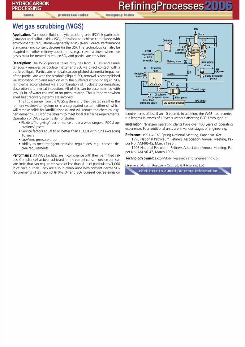
7/18/2019 Refining Processes Handbook 2006
http://slidepdf.com/reader/full/refining-processes-handbook-2006 220/222
adapted for other refinery applications, e.g., coke calciners when fluegases must be treated to reduce SOx and particulate emissions.
Description: The WGS process takes dirty gas from FCCUs and simul-taneously removes particulate matter and SOx via direct contact with abuffered liquid. Particulate removal is accomplished via inertial impactionof the particulate with the scrubbing liquid. SO2 removal is accomplishedvia absorption into and reaction with the buffered scrubbing liquid. SO3
removal is accomplished via a combination of nucleate condensation,absorption and inertial impaction. All of this can be accomplished with
low- (3-in. of water column) or no pressure drop. This is important whenaged heat recovery systems are involved.
The liquid purge from the WGS system is further treated in either therefinery wastewater system or in a segregated system, either of whichwill remove solids for landfill disposal and will reduce the chemical oxy-gen demand (COD) of the stream to meet local discharge requirements.Operation of WGS systems demonstrates:
• Flexible/”forgiving” performance under a wide range of FCCU op-erations/upsets
• Service factors equal to or better than FCCUs with runs exceeding
10 years• Low/zero pressure drop• Ability to meet stringent emission regulations, e.g., consent de-
cree requirements.
Performance: All WGS facilities are in compliance with their permitted val-ues. Compliance has been achieved for the current consent decree particu-late limits that can require emission of less than ½-lb of particulates /1,000lb of coke burned. They are also in compliance with consent decree SO2 requirements of 25 vppmd @ 0% O2 and SO3 consent decree emission
requirements of less than 10 vppmd. In addition, the WGS has recordedrun lengths in excess of 10 years without affecting FCCU throughput.
Installation: Nineteen operating plants have over 400 years of operatingexperience. Four additional units are in various stages of engineering.
Reference: 1991 AIChE Spring National Meeting, Paper No. 62c.1990 National Petroleum Refiners Association Annual Meeting, Pa-
per No. AM-90-45, March 1990.1996 National Petroleum Refiners Association Annual Meeting, Pa-
per No. AM-96-47, March 1996.
Technology owner: ExxonMobil Research and Engineering Co.
Licensor: Hamon Research-Cottrell, GN-Hamon, LLC.
�
Wet scrubbing system, EDVApplication: EDV Technology is a low pressure drop scrubbing system,to scrub particulate matter (including PM2.5), SO2 and SO3 from fluegases. It is especially well suited where the application requires high reli-ability, flexibility and the ability to operate for 4 – 7 years continuously

7/18/2019 Refining Processes Handbook 2006
http://slidepdf.com/reader/full/refining-processes-handbook-2006 221/222
without maintenance shutdowns. The EDV technology is highly suitedfor FCCU regenerator flue-gas applications.
Products: The effluents from the process will vary based on the re-agent selected for use with the scrubber. In the case where a sodium-based reagent is used, the product will be a solution of sodium salts.Similarly, a magnesium-based reagent will result in magnesium salts.A lime/limestone-based system will produce a gypsum waste. The EDVtechnology can also be used with the LABSORB buffer thus makingthe system regenerative. The product, in that case, would be a usable
condensed SO 2 stream.
Description: The flue gas enters the spray tower through the quenchsection where it is immediately quenched to saturation temperature.It proceeds to the absorber section for particulate and SO2 reduction.The spray tower is an open tower with multiple levels of BELCO-G-Nozzles. These nonplugging and abrasion-resistant nozzles removeparticulates by impacting on the water/reagent curtains. At the sametime, these curtains also reduce SO 2 and SO 3 emissions. The BELCO-G-Nozzles are designed not to produce mist; thus a conventional mist
eliminator is not required.Upon leaving the absorber section, the saturated gases are direct-ed to the EDV filtering modules to remove the fine particulates and ad-ditional SO3. The filtering module is designed to cause condensation ofthe saturated gas onto the fine particles and onto the acid mist, thusallowing it to be collected by the BELCO-F-Nozzle located at the top.
To ensure droplet-free stack, the flue gas enters a droplet separa-tor. This is an open design that contains fixed-spin vanes that induce acyclonic flow of the gas. As the gases spiral down the droplet separa-tor, the centrifugal forces drive any free droplets to the wall, separat-
ing them from the gas stream.
Economics: The EDV wet scrubbing system has been extremely suc-cessful in the incineration and refining industries due to the very highscrubbing capabilities, very reliable operation and reasonable price.
Installation: More than 200 applications worldwide on various pro-cesses including 43 FCCU applications, 5 heater applications, 1 SRUtailgas unit and 1 fluidized coker application to date.
Reference: Confuorto and Weaver, “Flue gas scrubbing of FCCU re-generator flue gas—performance, reliability, and flexibility—a case his-tory,” Hydrocarbon Engineering, 1999.
Eagleson and Dharia, “Controlling FCCU emissions,” 11th Refin-ing Technology Meeting, HPCL, Hyderabad, 2000.
Licensor: Belco Technologies Corp.
�
White oil and wax hydrotreatingApplication: Process to produce white oils and waxes.
Feeds: Nonrefined as well as solvent- or hydrogen-refined naphthenic orparaffinic vacuum distillates or deoiled waxes.

7/18/2019 Refining Processes Handbook 2006
http://slidepdf.com/reader/full/refining-processes-handbook-2006 222/222
Products: Technical- and medical-grade white oils and waxes for plasti-cizer, textile, cosmetic, pharmaceutical and food industries. Products arein accordance with the US Food and Drug Administration (FDA) regula-tions and the German Pharmacopoeia (DAB 8 and DAB 9) specifications.
Description: This catalytic hydrotreating process uses two reactors. Hydro-gen and feed are heated upstream of the first reaction zone (containing aspecial presulfided NiMo/alumina catalyst) and are separated downstreamof the reactors into the main product and byproducts (hydrogen sulfideand light hydrocarbons). A stripping column permits adjusting product
specifications for technical-grade white oil or feed to the second hydro-genation stage.
When hydrotreating waxes, however, medical quality is obtainedin the one-stage process. In the second reactor, the feed is passedover a highly active hydrogenation catalyst to achieve a very low levelof aromatics, especially of polynuclear compounds. This scheme per-mits each stage to operate independently and to produce technical- ormedical-grade white oils separately. Yields after the first stage rangefrom 85% to 99% depending on feedstock. Yields from the second
Installation: Four installations use the Uhde (Edeleanu) proprietary tech-nology, one of which has the largest capacity worldwide.
Licensor: Uhde GmbH.
�
�
�


![Hydrocarbon Processing Refining Processes 2000[2]](https://static.fdocuments.in/doc/165x107/577cb99d1a28aba7118d7d9a/hydrocarbon-processing-refining-processes-20002.jpg)


