Reference Point 1 Specification - OBSAI - OBSAI Spec v2_1.pdf · Use of an OBSAI reference or...
124
Reference Point 1 Specification Version 2.1 Issue 2-1 1 (124) Copyright 2008, OBSAI, All Rights Reserved.
Transcript of Reference Point 1 Specification - OBSAI - OBSAI Spec v2_1.pdf · Use of an OBSAI reference or...

Reference Point 1 Specification Version 2.1
Issue 2-1 1 (124)
Copyright 2008, OBSAI, All Rights Reserved.

Reference Point 1 Specification
Issue 2-1 2 (124)
Copyright 2008, OBSAI, All Rights Reserved.
Table of Contents
1 Summary of changes ......................................................................................... 6 2 Scope .................................................................................................................. 8 3 Control / Management Plane Topology ............................................................ 9 4 Control / Management Protocol Architecture .................................................. 9
4.1 Basic Principles ............................................................................................. 9 4.2 Physical Layer (Layer 1) ............................................................................... 9 4.3 Data Link Layer (Layer 2) .............................................................................. 9 4.4 Network Layer (Layer 3) ................................................................................ 9 4.5 Transport Layer (Layer 4) ........................................................................... 10 4.6 Upper Layers .............................................................................................. 10
5 Control Plane .................................................................................................... 11 5.1 BTS External Protocols ............................................................................... 11 5.2 BTS Internal Protocols ................................................................................ 14
5.2.1 Design Principles ................................................................................. 14 6 Management Plane ........................................................................................... 18
6.1 BTS External Protocols ............................................................................... 18 6.2 BTS Internal Protocols ................................................................................ 19
7 OAM&P Interfaces- General ............................................................................ 21 7.1 Modeling XML Schema in OBSAI ............................................................... 22
7.1.1 Element Definition ................................................................................ 22 7.1.2 Attribute Definitions .............................................................................. 23
8 RP1 - Synchronization Plane ........................................................................... 25 8.1 Synchronization Hierarchy .......................................................................... 25 8.2 Time and Frequency Reference .................................................................. 25
8.2.1 Transport Module ................................................................................. 25 8.2.2 Proprietary Module (PM) ...................................................................... 26
8.3 System Clock .............................................................................................. 26 8.4 Time Synchronization .................................................................................. 27
8.4.1 Synchronization Burst Format .............................................................. 27 8.5 Synchronization Network- Physical Layer ................................................... 30 8.6 Synchronization Network- Topology ............................................................ 31

Reference Point 1 Specification
Issue 2-1 3 (124)
Copyright 2008, OBSAI, All Rights Reserved.
Appendix A : UDPCP Specification and Example of SOAP Binding .............. 32 Appendix B Fault Management .......................................................................... 50 Appendix C Performance Management ............................................................. 58 Appendix D Configuration Management ........................................................... 84 Appendix E Software Management ................................................................. 106 Glossary ................................................................................................................. 115
Abbreviations ....................................................................................................... 115 Definition of Terms ............................................................................................... 121
References ............................................................................................................. 123

Reference Point 1 Specification
Issue 2-1 4 (124)
Copyright 2008, OBSAI, All Rights Reserved.
FOREWORD 1 2 3 4 5 6 7 8
9
10 11
12 13 14 15 16 17 18 19 20 21 22 23 24 25 26 27 28 29 30 31 32 33 34 35 36 37 38 39 40 41 42 43
OBSAI description and specification documents are developed within the Technical Working Group of the Open Base Station Architecture Initiative Special Interest Group (OBSAI SIG). Members of the OBSAI TWG serve voluntarily and without compensation. The description and specifications developed within OBSAI represent a consensus of the broad expertise on the subject within the OBSAI SIG. The OBSAI SIG uses the following terminology in the specifications:
• "shall" expresses a provision that is binding
• "should" and "may" expresses non-mandatory provisions
• "will" expresses a declaration of purpose on the part of the OBSAI SIG. It may be necessary to use "will" in cases where the simple future tense is required
Use of an OBSAI reference or specification document is wholly voluntary. The existence of an OBSAI Specification does not imply that there are no other ways to produce, test, measure, purchase, market, or provide other goods and services related to the scope of the OBSAI Specification. Furthermore, the viewpoint expressed at the time a specification is approved and issued is subject to change brought about through developments in the state of the art and comments received from users of the specification. Every OBSAI Specification is subjected to review in accordance with the Open Base Station Architecture Initiative Rules And Procedures. Implementation of all or part of an OBSAI Specification may require licenses under third party intellectual property rights, including without limitation, patent rights (such a third party may or may not be an OBSAI Member). The Promoters of the OBSAI Specification are not responsible and shall not be held responsible in any manner for identifying or failing to identify any or all such third party intellectual property rights. The information in this document is subject to change without notice and describes only the product defined in the introduction of this documentation. This document is intended for the use of OBSAI Member’s customers only for the purposes of the agreement under which the document is submitted, and no part of it may be reproduced or transmitted in any form or means without the prior written permission of OBSAI Management Board. The document has been prepared for use by professional and properly trained personnel, and the customer assumes full responsibility when using it. OBSAI Management Board, Marketing Working Group and Technical Working Group welcome

Reference Point 1 Specification
Issue 2-1 5 (124)
Copyright 2008, OBSAI, All Rights Reserved.
1 2 3 4 5 6 7 8 9
10 11 12 13 14 15 16 17 18 19 20 21 22 23 24 25 26 27 28 29 30 31 32 33 34 35 36 37 38 39 40 41
customer comments as part of the process of continuous development and improvement of the documentation. The information or statements given in this document concerning the suitability, capacity, or performance of the mentioned hardware or software products cannot be considered binding but shall be defined in the agreement made between OBSAI members. However, the OBSAI Management Board, Marketing Working Group or Technical Working Group have made all reasonable efforts to ensure that the instructions contained in the document are adequate and free of material errors and omissions. OBSAI liability for any errors in the document is limited to the documentary correction of errors. OBSAI WILL NOT BE RESPONSIBLE IN ANY EVENT FOR ERRORS IN THIS DOCUMENT OR FOR ANY DAMAGES, INCIDENTAL OR CONSEQUENTIAL (INCLUDING MONETARY LOSSES), that might arise from the use of this document or the information in it. This document and the product it describes are considered protected by copyright according to the applicable laws. OBSAI logo is a registered trademark of Open Base Station Architecture Initiative Special Interest Group. Other product names mentioned in this document may be trademarks of their respective companies, and they are mentioned for identification purposes only. Copyright © Open Base Station Architecture Initiative Special Interest Group. All rights reserved. Users are cautioned to check to determine that they have the latest edition of any OBSAI Specification. Interpretations: Occasionally questions may arise regarding the meaning of portions of standards as they relate to specific applications. When the need for interpretations is brought to the attention of OBSAI, the OBSAI TWG will initiate action to prepare appropriate responses. Since OBSAI Specifications represent a consensus of OBSAI Member’s interests, it is important to ensure that any interpretation has also received the concurrence of a balance of interests. For this reason OBSAI and the members of its Technical Working Groups are not able to provide an instant response to interpretation requests except in those cases where the matter has previously received formal consideration. Comments on specifications and requests for interpretations should be addressed to:
Peter Kenington Chairman, OBSAI Technical Working Group Linear Communications Consultants Ltd. Email: [email protected]

Reference Point 1 Specification
Issue 2-1 6 (124)
Copyright 2008, OBSAI, All Rights Reserved.
1 Summary of changes
Version Approved by Date Comment
1.0 OBSAI Management Board
10/17/2003 Initial Release
1.05 Draft 08/19/2004 Updated BTS Reference Architecture, .
Updated System Clock parameters in sections 8.3 and 8.4.
Defined the CRC generator polynomial for Synchronization Burst messages in sections 8.4.1.4
Updated UDPCP Specification in Appendix A. See section A.6 for detailed UDPCP revision history.
Updated OAM&P – Interfaces General section.
Appended Fault Management Specification in Appendix B.
Appended Performance Management Specification in Appendix C.
Appended Configuration Management Specification in Appendix D.
Appended Software Management Specification in Appendix E.
1.1 OBSAI Management Board
08/19/2004 Updated release
1.1.06 Draft 02/24/2005 Added reference to Test Messages Specification (section 7 and References)
Definition of “change” operation of <modifyParameterReq> corrected in D.4.5.1
Modified UDPCP protocol. Version number incremented to 002.
1.1.07 Proposal approval 06/15/2005 Agreed SW updates included
Reference Point 1 Specification
Issue 2-1 7 (124)
Copyright 2008, OBSAI, All Rights Reserved.
2.0 OBSAI Management Board
04/27/2006 CRC initialization change
WiMAX synchronization burst inclusion
Editorial improvements for synchronization
New architecture diagram incorporated
2.01 Draft 05/24/07 Minor editorial corrections and minor additions to incorporate LTE
2.02 Draft 03/03/08 Minor updates to pictures
2.1 OBSAI Management Board
07/14/2008 LTE Update release

Reference Point 1 Specification
Issue 2-1 8 (124)
Copyright 2008, OBSAI, All Rights Reserved.
2 Scope 1
This document specifies Reference Point 1 characteristics for the Control Plane (C-Plane, also known as "signaling") and Management Plane (M-Plane, also known as "OAM&P").
2 3 4 5 6 7 8 9
10 11 12 13 14 15 16 17 18
The User Plane (U-Plane, also known as "payload") belongs to RP2 and RP3. Nevertheless, RP1 and RP2 shall use a common BTS internal transport infrastructure. That means that the same protocol specifications (layer 1 to 3) apply for both Reference Points. In this document, references are made to respective chapters of the “Reference Point 2 Specification”. Chapter 3 and Chapter 4 of this specification describe the Reference Point 1 Control and Management Plane Topology and Architecture. Chapter 5 and chapter 6 of this specification describe the Reference Point 1 characteristics for the Control Plane and Management Plane. Chapter 7 describes general characteristics of OAM&P interfaces. Chapter 8 describes the Reference Point 1 characteristics for the Synchronization Plane.

Reference Point 1 Specification
Issue 2-1 9 (124)
Copyright 2008, OBSAI, All Rights Reserved.
3 Control / Management Plane Topology 1
This applies to both RP1 and RP2. Refer to “Reference Point 2 Specification”.
2 3
6 7 8 9
10 11
13 14
16 17
19 20
4 Control / Management Protocol Architecture 4
4.1 Basic Principles 5
This applies to both RP1 and RP2. Refer to “Reference Point 2 Specification”. OBSAI RP1 uses the IP family of protocols, for example bit presentation uses network bit order (which is generally used in the IP family of protocols). Principles from the IP family of protocols shall also be used within OBSAI.
4.2 Physical Layer (Layer 1) 12
This applies to both RP1 and RP2. Refer to “Reference Point 2 Specification”.
4.3 Data Link Layer (Layer 2) 15
This applies to both RP1 and RP2. Refer to “Reference Point 2 Specification”.
4.4 Network Layer (Layer 3) 18
This applies to both RP1 and RP2. Refer to “Reference Point 2 Specification”.

Reference Point 1 Specification
Issue 2-1 10 (124)
Copyright 2008, OBSAI, All Rights Reserved.
1
3 4 5 6
7
8
9
11
4.5 Transport Layer (Layer 4) 2
Interfaces associated with RP1 shall support the following Transport Layer protocols for the Control & Management Plane, appropriate to the Upper Layer (see section 4.6) protocol in use:
• TCP [RFC793]
• SCTP [RFC2960]
• UDPCP [Appendix A]
4.6 Upper Layers 10
RP1 related Upper Layer protocols fall into following categories: 1. BTS external Control Plane protocols (see chapter 5.1) 12
13 2. BTS internal Control Plane protocols (see chapter 5.2) 14
15 3. BTS external Management Plane protocols (see chapter 6.1) 16
17 4. BTS internal Management Plane protocols (see chapter 6.2) 18
19
20
Reference Point 1 Specification
Issue 2-1 11 (124)
Copyright 2008, OBSAI, All Rights Reserved.
5 Control Plane 1
5.1 BTS External Protocols 2
External Radio Network Layer (RNL) protocols have been defined by standardization bodies dedicated to the specification of RAN/BSS functions. They are beyond the scope of OBSAI. 3G examples are
3 4 5
6
7 8 9
10 11 12 13 14 15 16 17 18 19 20 21
• 3GPP Iub NBAP [3GPP TS 25.433]
• 3GPP2 Abis/A3 External Control Plane protocols are terminated at the CCM. The TM shall pass through respective PDU's transparently and shall not perform any protocol termination or conversion of RNL protocols. The corresponding protocol architecture may be different depending upon the characteristics of the Network Interface. The TM shall perform an interworking function at the transport layer to adapt the external protocol to either SCTP/IP or TCP/IP if the transport protocol at the network interface is different from that. The TM shall further encapsulate the data into the network, data-link, and physical layers as defined in the following figure. It is permissible to extend SCTP/IP or TCP/IP to the baseband module where required. This can be beneficial in, for example, 3GPP LTE systems.

Reference Point 1 Specification
Issue 2-1 12 (124)
Copyright 2008, OBSAI, All Rights Reserved.
IPv6(IPv4 opt.)
802.3 MACNetwork I/Fdependent
Network I/Fdependent
NetworkInterface(s)
RNL
TNL
802.3 MAC
IPv6(IPv4 opt.)
TM CCM
802.3 PHY100Base-TX1000BaseT
802.3 PHY100Base-TX1000BaseT
C-Plane App.(e.g. NBAP)
SCTPTCP
C-Plane(ext.)
Network I/Fdependent
SCTPTCP
Network I/Fdependent
*
1 2 3 4 5 6 7 8
Figure 1 Protocol Architecture- TM Provides Transport Layer IWF
* Additional termination points may be located in TM, depending on the Network Interface type.
Reference Point 1 Specification
Issue 2-1 13 (124)
Copyright 2008, OBSAI, All Rights Reserved.
IPv6(IPv4 opt.)
802.3 MACNetwork I/Fdependent
Network I/Fdependent
NetworkInterface(s)
RNL
TNL
802.3 MAC
IPv6(IPv4 opt.)
TM CCM
802.3 PHY100Base-TX1000BaseT
802.3 PHY100Base-TX1000BaseT
C-Plane App.(e.g. NBAP)
SCTPTCP
C-Plane(ext.)
1 2 3
4 5 6 7 8
9
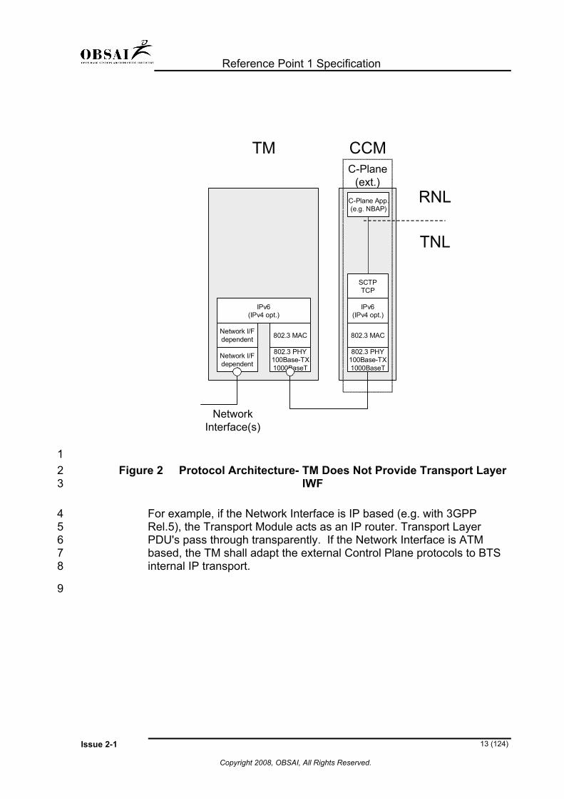
Figure 2 Protocol Architecture- TM Does Not Provide Transport Layer IWF
For example, if the Network Interface is IP based (e.g. with 3GPP Rel.5), the Transport Module acts as an IP router. Transport Layer PDU's pass through transparently. If the Network Interface is ATM based, the TM shall adapt the external Control Plane protocols to BTS internal IP transport.

Reference Point 1 Specification
Issue 2-1 14 (124)
Copyright 2008, OBSAI, All Rights Reserved.
5.2 BTS Internal Protocols 1
Internal call processing signaling between the CCM and the other modules occurs over the RP1 Control plane. This signaling covers management of radio and other system resources of the OBSAI BTS.
2 3 4
6 7 8 9
10 11 12 13 14 15 16 17 18 19 20 21 22 23 24
5.2.1 Design Principles 5
The OBSAI architecture for supporting communication between the CCM and the other modules in the BTS shall support a direct interface, an indirect interface or a combination of both. Regardless of the interface chosen, the communication shall be socket based. For all internal communications, TCP or UDPCP shall be used at the transport layer. Module resource management application (MRMA) software responsible for module level resource management shall reside on the local hardware (for example, the BBM MRMA shall reside on the BBM). The overall management of the BTS level radio and shared system resources shall be performed by the BTS resource manager (BRM) resident on the CCM. The MRMAs shall communicate with the BRM via a direct interface or an indirect interface as described in sections 5.2.1.1 and 5.2.1.2 respectively. All module vendors shall be responsible for providing the MRMA resident on their modules. However, the BRM shall be the responsibility of the BTS integrator. The implementation details of the MRMA and BRM are out of scope of this specification.

Reference Point 1 Specification
Issue 2-1 15 (124)
Copyright 2008, OBSAI, All Rights Reserved.
5.2.1.1 Direct Interface 1 The direct interface as shown in Figure 3 implies direct communication between the BRM and the MRMAs. This interface is undefined above the transport layer in this release of the RP1 specification.
2 3 4 5
TM BBM V1 BBM V2 RFM PM
OBSAI BTS
TM MRMA
CCMBTS
Resource Manager(BRM)
BBM V1MRMA
RFM MRMA
BBM V2MRMA
PM MRMA
V1: Vendor 1V2: Vendor 2
OBSAI specified.Proprietary implementation is out of OBSAI scope.
6 7
8 9
Figure 3 Direct Interface

Reference Point 1 Specification
Issue 2-1 16 (124)
Copyright 2008, OBSAI, All Rights Reserved.
5.2.1.2 Indirect Interface 1 The indirect interface shown in Figure 4 implies that the communication between the BRM and the MRMAs occurs indirectly via proxies. The module vendor shall provide the MRMA Proxy software resident on the CCM in addition to the MRMA (i.e., the BBM vendor shall provide the BBM MRMA as well as the BBM MRMA Proxy).
2 3 4 5 6 7 8 9
10 11 12 13
A single MRMA Proxy shall be loaded on the CCM for each module type. For example, in a BTS with multiple CDMA BBMs, a single instantiation of the BBM MRMA Proxy shall reside on the CCM or the two TMs of a redundant BTS shall be served by a single TM MRMA Proxy. The interface between the BRM and the MRMA proxies may be OBSAI specified or BTS integrator proprietary.
TM BBM V1 BBM V2 RFM PM
OBSAI BTS
TM MRMA
CCMBRM
TMMRMA Proxy
BBM V1MRMA Proxy
BBM V2MRMA Proxy
RFMMRMA Proxy
PMMRMA Proxy
BBM V1 MRMA
RFM MRMA
BBM V2 MRMA
PMMRMA
OBSAI specified or proprietary.Vendor choice.Proprietary implementation is out of OBSAI scope.
V1: Vendor 1V2: Vendor 2
14 15 16 17 18 19 20 21 22 23 24
Figure 4 Indirect Interface With this revision of the RP1 specification, it is expected that all modules of the same function/mode (e.g., TM, CCM) will be manufactured by the same vendor. This will enable effective resource management of N instances of a particular module type without specifying protocols and messages required for inter-module communication across different vendors’ modules. Concurrent BTS operation with more than one access technology can be accommodated by loading appropriate MRMA proxies.

Reference Point 1 Specification
Issue 2-1 17 (124)
Copyright 2008, OBSAI, All Rights Reserved.
NetworkInterface(s)
RNL
TNL
BBM/RFM
802.3 MAC
IPv6(IPv4 opt.)
TCPUDPCP
MRMA
C-Plane(int.)
802.3 PHY100Base-TX1000Base-T
802.3 MAC
TM
802.3 PHY100Base-TX/1000Base-T
802.3 MAC
IPv6(IPv4 opt.)
CCM
802.3 PHY100Base-TX1000BaseT
TCPUDPCP
BRM MRMAProxies
TCP
C-Plane(ext.)
C-Plane(int.)
1 2 3 4
5
Figure 5 Indirect Interface Examples: BBM/RFM
Signaling

Reference Point 1 Specification
Issue 2-1 18 (124)
Copyright 2008, OBSAI, All Rights Reserved.
6 Management Plane 1
6.1 BTS External Protocols 2
Although external OAM&P protocols (e.g. SNMP, TELNET/CLI) are not specified by OBSAI, they are assumed to be IP based. The protocols are terminated at the CCM.
3 4 5 6 7 8 9
10 11 12
There are no conceptual differences with regard to the characteristics of the Network Interface (ATM or IP). The Transport Module always acts as an IP router for external OAM&P protocols. In case of an ATM based Network Interface, OAM&P related IP datagrams are adapted to ATM cells (AAL5) for transport over the RAN. The figure below illustrates the protocol architecture.

Reference Point 1 Specification
Issue 2-1 19 (124)
IPv6/IPv4
802.3 MACNetwork I/Fdependent
Network I/Fdependent
NetworkInterface(s)
802.3 MAC
IPv6/IPv4
TM CCM
802.3 PHY100Base-TX1000BaseT
802.3 PHY100Base-TX1000BaseT
BTS MasterAgent
M-Plane(ext.)
TCPUDP
1 2
4 5 6 7 8 9
10 11 12 13
Figure 6 External Management Plane
6.2 BTS Internal Protocols 3
Control, status and alarm data sent between a BTS Master Agent and the Module Agents shall be coded in Simple Object Access Protocol [SOAP] messages. A corresponding parser does not need to be a validating one. SOAP can potentially be used in combination with a variety of transport protocols. The transport protocol options specified by OBSAI are TCP and UDPCP. The figure below illustrates the protocol architecture that supports communication between the BTS Master Agent and Module Agents.
Copyright 2008, OBSAI, All Rights Reserved.

Reference Point 1 Specification
Issue 2-1 20 (124)
Copyright 2008, OBSAI, All Rights Reserved.
IPv6(IPv4 opt.)
802.3 MAC
NetworkInterface(s)
802.3 MAC
IPv6(IPv4 opt.)
TM BBM/RFMCCM
802.3 PHY100Base-TX1000BaseT
802.3 PHY100Base-TX1000BaseT
M-Plane(int.)
802.3 MAC
IPv6(IPv4 opt.)
802.3 PHY100Base-TX1000BaseT
M-Plane(int.)
ModuleAgent
CCMAgent
BTS MasterAgent
TMAgent
SOAP/XML SOAP/XMLSOAP/XML
TCPUDPCP
M-Plane(int.)
TCPUDPCP
TCPUDPCP
1 2 3
Figure 7 Internal Management Plane

Reference Point 1 Specification
Issue 2-1 21 (124)
Copyright 2008, OBSAI, All Rights Reserved.
7 OAM&P Interfaces- General 1
This section specifies aspects common to all OAM&P functions at the RP1 interface. Definition of terms associated with each aspect of OAM&P is in accordance with those provided by ITU, 3GPP, 3GPP2 and other industry management standards. These concepts and the corresponding SOAP message structures are defined.
2 3 4 5 6 7
8 9
10
It is assumed that the reader is familiar with the following:
• OAM&P principles described in the OBSAI System Reference Document.
• General concepts of XML and SOAP defined by W3C (www.w3c.org). 11
12 13 14 15
The messages are based on usage scenarios specified by the W3C. All SOAP header elements must be namespace qualified. For example, for RP1 the namespace is “http://www.obsai.org/oamp/2004/09/rp1”. Header
16 17
18 The Header element contains the following elements:
Element Name Usage
to Specifies the address of the message receiver.
from Specifies the address of the message sender.
Id The id is used by the sender to uniquely identify the request or notification. The value is assigned by the sender during creation of the request or notification. The sender has to ensure that the value is unique in the scope of the sender.
RelatesTo Reference identifier to correlate request/response message pairs.
If the receiver receives the Request message and the id is non-null and non-empty, it copies it to the Response or Exception message (i.e. receiver shall reply with same string by copying the received value to the response or error message).

Reference Point 1 Specification
Issue 2-1 22 (124)
Copyright 2008, OBSAI, All Rights Reserved.
Action Defines the intent/type of the message as follows:
Fault Management: ”OBSAI_FM”
Performance Management: ”OBSAI_PM”
Configuration Management: ”OBSAI_CM”
Software Management: ”OBSAI_SwM”
Test : ”OBSAI_Test”. Test messages are specified in [OBSAI_Test]. Other vendor specific values may also be specified.
Version Specifies the version of the OAM&P fragment that this message belongs to.
For example, if the action is “OBSAI_FM” and version is 1.1, then this message is an FM message from FM fragment version 1.1.
responseRequested If included in the header, this indicates that the receiver is required to respond to the message.
1 Body
2 3
4 5 6 7 8 9
11 12 13 14 15 16
18 19 20
The Body element contains the payload of the message (i.e. where the main end-to-end information is conveyed). The tag of the first element in the body in a message shall contain the message name. All timestamp information in the body of OBSAI OAM&P messages shall be formatted in Coordinated Universal Time (UTC) according to XML datatype “dateTime” (e.g. YYYY-MM-DDThh:mm:ssZ).
7.1 Modeling XML Schema in OBSAI 10
The following section provides guidelines for modeling XML Schema for the OBSAI OAM&P specification. This guideline provides recommended practices on how to model the XML schema that is used to validate the XML file. The following design guidelines for XML elements are applicable in the scope of OAM&P.
7.1.1 Element Definition 17
Element Definitions specify a type definition for an element by either reference or explicit Datatype. The element type can be a built-in data type defined in the XML Schema language or a user-defined Datatype

Reference Point 1 Specification
Issue 2-1 23 (124)
Copyright 2008, OBSAI, All Rights Reserved.
(using the simpleType or Complex Type element definitions). Below is an example of an element definition: <element name="<elementName>" type ="<Datatype>" default=”<Value>” nillable="true" minOccurs=0 maxOccurs=1/> The first letter of the <elementName> shall be lower case and any subsequent word that is embedded in the name shall begin with an upper case letter followed by a lower case letter. In case the element contains no valid data (e.g. "null" value in a database table) it shall be marked by using the nillable attribute in XML. <element name=”code” nillable=”true”/> If the element can be empty (i.e. no value) then the minOccurs attribute shall be used.
1 2 3 4 5 6 7 8 9
10 11 12 13 14 15 16 17 18
20 21
23 24 25 26 27 28 29 30
32 33 34 35 36 37 38
7.1.2 Attribute Definitions 19
The first letter of the <attributeName> name is to be lowercase.
7.1.2.1 Complex Type/Simple Type Definitions 22 Type definitions in XML schema are defined using the Complex Type element and simpleType element. The first letter of the <Complex TypeName> and <SimpleTypeName> name is to be an upper case letter followed by a lower case letter, and any subsequent word that is embedded in the name shall begin with an upper case letter followed by a lower case letter.
7.1.2.2 Comments in XML schema 31 Comments in the XML schema are represented using the annotation tag: <annotation> <documentation>Documentation Text</documentation> </annotation>

Reference Point 1 Specification
Issue 2-1 24 (124)
Copyright 2008, OBSAI, All Rights Reserved.
7.1.2.3 Modeling Date types in XML 1 XML built-in datatypes as defined by W3C shall be used. 2
4
6 7
7.1.2.4 Modeling Arrays in XML 3 XML built-in datatypes as defined by W3C shall be used.
7.1.2.5 Modeling Enumerations in XML 5 XML built-in datatypes as defined by W3C shall be used.

Reference Point 1 Specification
Issue 2-1 25 (124)
Copyright 2008, OBSAI, All Rights Reserved.
8 RP1 - Synchronization Plane 1
8.1 Synchronization Hierarchy 2
The synchronization hierarchy and basic principles are described in the “OBSAI System Reference Document”
3 4
7 8 9
10 11 12 13
14
15 16
17 18 19 20 21
8.2 Time and Frequency Reference 5
8.2.1 Transport Module 6
The TM shall provide synchronization information, such as clock and Synchronization Status Messages (SSM) extracted from the Network Interface. The TM shall provide the derived clock and SSM to the CCM for further processing to generate the BTS system clock and time reference signals. In addition, the TM may be able to synchronize the Network Interfaces based on the following:
• System clock provided by CCM
• A clock reference recovered from a selected ingress Network Interface
• A free running clock The TM and the CCM shall negotiate Clock and Frequency Reference selection to select proper reference clock input where there is more than one source available.

Reference Point 1 Specification
Issue 2-1 26 (124)
Copyright 2008, OBSAI, All Rights Reserved.
8.2.2 Proprietary Module (PM) 1
A PM may take many forms, although one likely form is that of a module to provide system time and a frequency reference, based on Global Positioning System (GPS) time. If used for this purpose, the PM shall provide the following signals to the CCM:
2 3 4 5
6 7 8 9
10 11 12 13 14 15
17 18 19 20 21 22 23 24 25 26 27 28 29 30 31 32 33 34 35
• A system time reference synchronous to UTC time (except for leap seconds) with the same time origin as GPS time. This information is transported in a System Time Message (STM) over the C-Plane infrastructure.
• A one pulse per second (PPS) reference clock, synchronized to GPS, over a dedicated link. This signal serves to validate the STM (mentioned above) providing the means of delivering highly accurate system time information to the CCM. Additionally, PPS serves as a frequency reference from which the CCM can generate the system clock.
8.3 System Clock 16
The CCM shall provide a common system clock to the BBM, RFM, TM and PMs. This common system clock will be used as a frequency reference for all modules in the system and shall support concurrent operation of WCDMA, CDMA2000, GSM/EDGE, WiMAX and 3GPP LTE. The system clock is delivered through the use of a single clock network. The CCM shall provide the system clock to all modules contained within its shelf. This shall be accomplished over dedicated, point-to-point links. Additionally, the CCM shall provide one extra system clock output for the purposes of delivering a frequency reference to an Extension Module that may be located in an additional shelf. All modules receiving the system clock shall contain two clock inputs- one from each of the CCMs that comprise a redundant pair. See Figure 11 for a description of the synchronization network topology. The system clock shall be a digital signal operating with the parameters described in Table 1. Additionally, the System Clock shall conform to requirements for wander generation, tolerance, and transfer according to G.812, Type II.

Reference Point 1 Specification
Issue 2-1 27 (124)
Copyright 2008, OBSAI, All Rights Reserved.
Table 1 System Clock Operating Parameters 1
Parameter Symbol Values
Min Typical Max Unit Frequency FCLK -0.016
ppm 30.72 +0.016
ppm MHz
Duty Cycle TDUTY_CYCLE 40 50 60 %
PP Jitter TP-P JITTER -- 400 600 ps
8.4 Time Synchronization 2
Over a common synchronization network, the CCM shall provide frame timing and time stamping, for each of the air interface systems, independently. The time synchronization shall be provided via periodic synchronization bursts containing air-interface-specific frame numbers and time references. The CCM shall periodically cycle through each type of burst necessary for synchronization of the BTS. The CCM shall provide bursts with a minimum of 30 milliseconds between any two bursts.
3 4 5 6 7 8 9
10
12 13 14 15
8.4.1 Synchronization Burst Format 11
The synchronization bursts shall follow the message format in Figure 8, and conform to the frame timing in Figure 9. The LSB of each field shall be transmitted first. The length of each synchronization burst bit shall be eight periods of the System Clock.
Start1
Type8
Type Specific Information64
CRC16
End1
16 17 18 19 20
Figure 8 Synchronization Burst Format

Reference Point 1 Specification
Issue 2-1 28 (124)
Copyright 2008, OBSAI, All Rights Reserved.
Synchronization Burst, CCM Output
Synchronization Burst, as re-clocked within end point module
System Clock 30.72 MHz
1 2
4 5
7
Figure 9 Synchronization Burst Frame Timing
8.4.1.1 Start and End Definition 3 The Start and End bits shall be one bit in width and shall both be set to a “1”. The link shall be set to “0” between messages.
8.4.1.2 Type Field Definition 6
Type Bits Not Used 00h
RP3 Bus (FDD) Frame Number 01h
WCDMA/FDD Frame Number 02h
GSM/Edge1 Frame Number 03h
GSM/Edge2 Frame Number 04h
GSM/Edge3 Frame Number 05h
WCDMA/TDD Frame Number 06h
CDMA2000 Frame Number 07h
Time of Day 08h
Reserved 09h – 7Fh
802.16 Frame Number, 2 ms Frame Duration
80h
802.16 Frame Number, 2.5 ms Frame Duration
81h
802.16 Frame Number, 4 ms Frame Duration
82h
802.16 Frame Number, 5 ms Frame Duration (WiMAX Mandatory)
83h
802.16 Frame Number, 8 ms Frame Duration
84h

Reference Point 1 Specification
Issue 2-1 29 (124)
802.16 Frame Number, 10 ms Frame Duration
85h
802.16 Frame Number, 12.5 ms Frame Duration
86h
802.16 Frame Number, 20 ms Frame Duration
87h
3GPP LTE Frame Number 88h
Spare 89h - FFh
1 2 3 4 5 6 7 8 9
11 12
Figure 10 Synchronization Burst Format- Type Field Notes:
1. Any module receiving a synchronization burst of type “Spare” shall ignore the burst.
2. Any module receiving a synchronization burst of type “Reserved” shall send an appropriate alarm to the CCM.
8.4.1.3 Type Specific Information Field Definition 10 Frame Numbering Type Type Specific Information
01h-07h 80h-88h
Frame Number
13 14
15 16 17 18 19
Type Specific Information:
• Frame Number: Frame Number with reference to the corresponding air interface (64 bit, unsigned integer)
Time of Day Stamping Type Type Specific Information
08h Spare LeapSecs TODSrc GPSTime 20
21
22
Type Specific Information:
• Spare: Unused bits, shall be set to zero by the CCM. (16 bit)
Copyright 2008, OBSAI, All Rights Reserved.

Reference Point 1 Specification
Issue 2-1 30 (124)
Copyright 2008, OBSAI, All Rights Reserved.
• TODSrc: Time Of Day Source (8 bit, unsigned integer) shall be encoded as
1 2 3 4 5 6 7
8 9
10 11 12
14 15 16 17 18
19
20 21
23 24
o 01h: GPS o 02h: NTP (Network Time Protocol over Network Interface) o 03h: Real Time Clock o 04h: Time Since Power-Up (CCM keeps track of the
elapsed time since the last power cycle)
• LeapSecs: Time, in seconds, between GPS and UTC time (8 bit, signed integer)
• GPSTime: GPS Time, seconds since January 6, 1980 (32 bit, unsigned integer)
8.4.1.4 CRC Field Definition 13
The CRC field shall be a 16 bit sequence calculated over the Type and Type Specific Information fields of the message, starting with the left-most bit of the Type field (Figure 8). The following generator polynomial is used:
x16
+ x12
+ x5 +1
The initial value of the CRC shall be 0x0000.
8.5 Synchronization Network- Physical Layer 22
The physical layer for the synchronization network, both system clock and time synchronization (synchronization bursts) shall be LVDS.

Reference Point 1 Specification
Issue 2-1 31 (124)
Copyright 2008, OBSAI, All Rights Reserved.
2 3
8.6 Synchronization Network- Topology 1
The following figure details the synchronization network topology.
BB N/RF N
BB N/RF NCM 2CM 1 TM 2TM 1
LVDS
Reference Clock
System Clock + Time Sync
SHELF 1
BB N/RF N/GPM NEM 2EM 1
BB 1/RF 1/GPM 1
SHELF 2
To Next Shelf
GPM 2GPM 1
4 5 6 7
Figure 11 Synchronization Network Topology

Reference Point 1 Specification
Issue 2-1 32 (124)
Copyright 2008, OBSAI, All Rights Reserved.
Appendix A : UDPCP Specification and Example of SOAP Binding
1
2
3
4 5 6 7 8 9
10 11 12 13
A.1 Scope This appendix describes the UDP-based Communication Protocol (UDPCP) that is designed to meet the needs of Base Station internal communications. UDPCP provides reliable and unreliable transport services over UDP/IP so that it can be applied as a general purpose transport solution in Base Stations. In addition to the UDPCP specification this document also provides an example of XMLP (SOAP) layer binding to the UDPCP that is compliant with the W3C “XML Protocol Abstract Model” specification. The layered architecture of the UDPCP-based communication stack is illustrated below:
UDPCP
UDPCP Binding
Socket API
UDP
IPv4/IPv6
Managementservice
SOAP Application
UDPCP_Task
UDPCP_Communication service
Packet assembly/disassembly service
SOAP (XMLP)
14 15 16 17
Figure 12 Layered architecture of the UDPCP-based communication stack.

Reference Point 1 Specification
Issue 2-1 33 (124)
Copyright 2008, OBSAI, All Rights Reserved.
1
2
3
4
5
6
7
8 9
10 11
12
13 14 15 16 17 18 19 20
21
22
23
24
25
26
27
28
A.2 UDPCP Features The UDPCP communication service supports the following features:
• Connectionless communication for serial mode data transfer
• Acknowledged and unacknowledged transfer modes
• Retransmissions Algorithm
• Checksum Algorithm
• Fragmentation of long messages (dis-assembly/re-assembly) to match to the MTU during transport:
• Broadcasting and multicasting messages to multiple peers in unacknowledged transfer mode
A.3 UDPCP Transport Protocol UDPCP supports application level messages up to 64 KBytes (limited by 16-bit packet data length field). Messages that are longer than the MTU shall be fragmented. The protocol places the following restrictions upon the fragment that is submitted to the underlying UDP layer: - The size of a valid fragment shall be 12 octets minimum - The maximum size of a valid fragment shall conform to the MTU. UDPCP provides a reliable transport service that will perform message retransmissions in case transport failures occur
A.3.1 UDPCP Packet Types
There are two types of UDPCP packets:
• UDPCP Data Packet
• UDPCP Acknowledge Packet
A.3.2 Data Packet Transfer Modes
UDPCP supports the following:
• Acknowledged data packet transfer
• Unacknowledged data packet transfer

Reference Point 1 Specification
Issue 2-1 34 (124)
Copyright 2008, OBSAI, All Rights Reserved.
A.3.2.1 UDPCP Data Packet Format 1
2 3
A UDPCP Data Packet includes header and payload. The packet format is as shown below:
MsgType reserved
Checksum
PAYLOAD DATA (variable length in octets)
Fixed lengthmessageheader
0 1 2 3 4 5 6 7 8 9 0 10 1 2 3 4 5 6 7 8 9 0 1 2 3 4 5 6 7 8 90 1 2 3
Fragment Amount Fragment Number
Message ID Message Data Length
Version N C S D
4 5 6 7 8 9
10 11 12 13 14 15 16 17 18 19 20 21
22 23
24 25
26 27
Figure 13 UDPCP Data Packet Checksum: 32-bits (unsigned integer)
This field contains the Adler32 checksum value of the UDPCP Data packet. If the C-bit is set to 0 (i.e., checksum not in use), this field shall contain a value of 0. Note: A sample C code for computing Adler-32 checksum can be found in RFC 1950 and RFC 2960
Msg Type: 2-bits These bits indicate the message type. For a data packet this field shall be binary 01.
Version: 3-bits These bits indicate the protocol version. Packets conforming to this version of this UDPCP specification shall have this field set to 002 binary.
Packet Transfer Options (N, C, S, D and Reserved): 11-bits The individual bits of this field shall be used as follows:
• If the N-bit is 0, and the S-bit is 0, every packet shall be acknowledged.
• If the N-bit is 0 and the S-bit is 1 only the last fragment that completes the message shall be acknowledged.
• If the N-bit is 1 and S bit is “don’t care”, the packet or message shall not be acknowledged.

Reference Point 1 Specification
Issue 2-1 35 (124)
Copyright 2008, OBSAI, All Rights Reserved.
1 2 3
4
5
6 7 8 9
10 11 12 13 14 15 16 17 18 19 20 21 22
23
24 25 26
• If the C-bit is 1 the Checksum field contains the checksum of the UDPCP packet. If C-bit is 0, the Checksum field shall contain a value of 0.
• In a data packet the D-bit shall be set to 0.
• The Reserved-bits shall be set to 0.
Fragment Amount: 8-bits (unsigned integer) This field indicates the total number of fragments of a message. If a message is unfragmented this field may be 0 or 1.
Fragment Number: 8-bits (unsigned integer) This field shall be used to indicate the fragment number of the current packet in transport. The first fragment of the message shall have a value of 0.
Message ID: 16-bits (unsigned integer) This field contains a unique 16-bit message identifier. Generation of the message identifier is specified in A.3.2.3. Same Message ID value is used for all fragments belonging to the same message.
Message Data Length: 16-bits (unsigned integer) This field indicates the length of the payload data of the message in octets.
Payload Data: variable length in octets This field contains user data.
MSB = bit 0
A.3.2.2 UDPCP Acknowledge Packet Format
A receiver shall acknowledge reception of an error free packet or message in Acknowledged Transfer mode (N = 0). This packet has the following format:
0 1 2 3 4 5 6 7 8 9 0 10 1 2 3 4 5 6 7 8 9 0 1 2 3 4 5 6 7 8 90 1 2 3
Checksum
Reserved
Message ID Message Data Length = 0
Fixed lengthmessageFragment Amount Fragment NumberMsg
Type Version N C S D
27 28 29 30
Figure 14 UDPCP Acknowledge Packet
Checksum: 32-bits (unsigned integer)

Reference Point 1 Specification
Issue 2-1 36 (124)
Copyright 2008, OBSAI, All Rights Reserved.
This field contains the Adler32 checksum value of the UDPCP Acknowledge packet. If the C-bit is set to 0 (i.e., checksum not in use), this field shall contain a value of 0.
1 2 3 4 5 6 7 8 9
10 11 12 13
14 15 16
17 18 19
20
21 22 23 24 25 26 27 28 29 30 31 32
33
34 35 36
Msg Type: 2-bits These bits indicate the message type. For an Acknowledge packet, this field shall be binary 10.
Version: 3-bits These bits indicate the protocol version. Packets conforming to this version of this UDPCP specification shall have this field set to 002 binary.
Packet Transfer Options (N, C, S, D and Reserved): 11-bits The N and S bits of this field shall be set. The other bits shall be used as follows:
• If the C-bit is 1 the Checksum field contains the checksum of the UDPCP Acknowledge packet. If C-bit is 0, the Checksum field shall contain a value of 0.
• In an acknowledge packet the D-bit shall be set to 0 the first time a packet is acknowledged. The D bit may be set to 1 to indicate a duplicate data packet.
• The Reserved-bits shall be set to 0.
Fragment Amount: 8-bits (unsigned integer) This field contains a copy of the total number of fragments of the data packet being acknowledged.
Fragment Number: 8-bits (unsigned integer) This field contains a copy of the fragment number of the data packet being acknowledged.
Message ID: 16-bits (unsigned integer) This field contains a copy of the unique 16-bit message identifier of the packet being acknowledged.
Message Data Length: 16-bits (unsigned integer) The message data length field shall be set to 0 in the Acknowledge packet i.e. no payload bytes will be transported.
A.3.2.3 Message ID Generation and Synchronization
The transmitter shall guarantee that the Message ID in each message sent to a receiver is unique. During normal operation, the Message ID shall be non-zero.

Reference Point 1 Specification
Issue 2-1 )
1 2 3 4 5
6
7
8
9 10
11
12 13
14
15
16
17
18 19 20 21
22
However, to enable transmitter and receiver synchronization after a UDPCP reset, the first transmitted message shall have Message ID = 0 and shall be sent using acknowledged mode. This message is used only for synchronization and is hereafter referred to as Sync Msg. The Sync Msg shall have the following:
• Type = Data Packet
• Message Data Length = 0
• N-bit = 0
• S-bit = 0
A.3.2.4 Duplicate Message Detection
Duplicate Messages are detected by the receiver if all of the following are the same as those of the recent fragment(s):
• Fragment Amount
• Fragment Number
• Message ID
• Source IP Address
• Source Port The receiver should maintain the latest received message from each transmitter. The receiver shall acknowledge (with D-bit set to 1) and discard a duplicate fragment in acknowledge transfer mode.
A.4 UDPCP API
37 (124
Copyright 2008, OBSAI, All Rights Reserved.
messageReceived() messageReceived()
UDPCPService A
commInd() commInd()
UDPCPService B
confMessage() confMessage()
sendMessage() sendMessage()
23 24 25
Figure 15 UDPCP API Usage

Reference Point 1 Specification
Issue 2-1 38 (124)
Copyright 2008, OBSAI, All Rights Reserved.
The UDPCP provides an API to the upper layer applications that use the UDPCP Services. The UDPCP API shall have the following methods:
1 2 3
4 5
6 7
8 9
10
11
12 13 14 15 16 17 18
• sendMessage (to, opt, message): This method is used for sending a message with specified options (opt).
• messageReceived (from, message): This method is used for handling a received message.
• commInd (): This method is used to indicate communication status to the upper layers.
• confMessage (): UDPCP service configuration
A.4.1 Transmitter Functions
If acknowledge transfer mode is used, the transmitter shall wait for an acknowledge response for a configurable timeout period. If the transmitter does not receive the acknowledge message during this timeout period it shall resend the message with the same Message ID for a configurable retry count. Once the maximum number of retransmissions is exceeded, the transmitter should notify the upper layers of the failed transmission.

Reference Point 1 Specification
Issue 2-1 39 (124)
Copyright 2008, OBSAI, All Rights Reserved.
The following flowchart shows a simplified example of the transmitter software.
1 2
[No]
- - - Transmit Packet
Free Buffer
AcknowledgeRequired?
[No]
[Yes]
Acknowledgereceived?
[Yes]
[No]
Free Buffer
ResendTimeout?
Retransm.exceeded?
Timeout Loop
[Yes]
[Yes]
[No]
Retransmit Loop
Notify successfulpacket delivery
Notify failed packetdelivery
Send Packet
3 4
5
6 7 8 9
10 11 12 13 14
Figure 16 Simplified Transmitter Example Flowchart
A.4.2 Receiver Functions
Since the receiver function in the UDPCP Service may get corrupted or receive unknown fragments (not valid UDPCP packets) from the lower layers, it is more complex and must be capable of responding to many adverse situations. Some examples are listed here:
- The message cannot be delivered to the upper layers e.g. due to full buffers
- The message integrity check (checksum) fails i.e. it is corrupted - The message can be too long or short - The message is in the wrong format (no valid UDPCP header)

Reference Point 1 Specification
Issue 2-1 40 (124)
Copyright 2008, OBSAI, All Rights Reserved.
- Any combination of the above can occur 1 2 3 4 5 6 7 8 9
10 11 12 13 14 15
- The Acknowledge packet can be lost, causing the transmitter to send a duplicate copy of a message that has already passed to the upper layers
The receiver function shall silently discard all other types of packets from other peer(s) except valid UDPCP Data Packets or Acknowledge packets. If a received Data Packet is valid, the receiver sends an Acknowledge packet (acknowledge transfer mode) to the transmitter. When a complete message is received (all fragments of a long message or the single packet containing a non-fragmented message), the message and information about its sender are delivered to the upper layers. The following figure shows a simplified example of the receiver software.
Convert packet tohost endian
ReceivedData Packet?
[No]
[Yes]
Integrity OK?
Ackrequired?
[Yes]
[No]
[Yes]
Create Ackmessage
Messagecompleted?
Reassemblemessage
[No]
[Yes]
Free Buffer
[No] Received AckPacket?
Convert packet tohost endian
[Yes]
Free Buffer Free Buffer
[No]
- - - UDPPacketReceived
Send AckTomessage
Deliver messageto upper layer
DeliverAckToPacket
message
16 17
18
Figure 17 Simplified Receiver Example flowchart

Reference Point 1 Specification
Issue 2-1 41 (124)
Copyright 2008, OBSAI, All Rights Reserved.
A.4.3 Example Protocol Diagrams 1
2 3 4 5
The following figure shows an acknowledged message transfer. In this example it is assumed that the message length does not exceed the used maximum UDP packet size i.e. messages need not be fragmented at the UDPCP.
sendMessage(to, opt, message) Data
(messageHdr, message)messageReceived(from, message)
Acknowledge(messageHdr)
Transmitter AUDPCPService A
UDPCPService BReceiver A Transmitter B
Receiver B
6 7 8 9
10 11
Figure 18 Message transfer (no error) in Acknowledge mode (Non-Fragmented)
The following figure shows a message transfer with errors, in Acknowledge transfer mode. Again it is assumed that the message is not longer than the used maximum UDP packet size.
sendMessage(to, opt, message) Data
(messagHdr, message)Error
detected
Data(messageHdr, message) messageReceived
(from, message)Acknowledge(messageHdr)
re-transmitmessage
Transmitter AUDPCPService A
UDPCPService BReceiver A Transmitter B
Receiver B
12 13 14 15
Figure 19: Message transfer with error in Acknowledge mode (Non-fragmented)
Reference Point 1 Specification
Issue 2-1 42 (124)
Copyright 2008, OBSAI, All Rights Reserved.
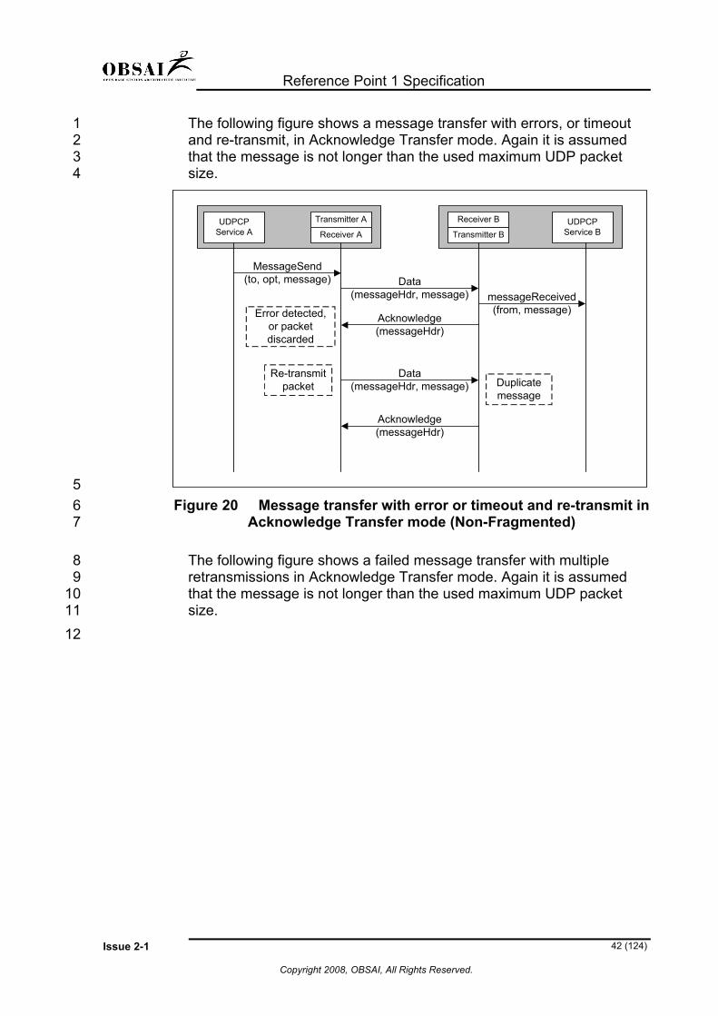
The following figure shows a message transfer with errors, or timeout and re-transmit, in Acknowledge Transfer mode. Again it is assumed that the message is not longer than the used maximum UDP packet size.
1 2 3 4
MessageSend(to, opt, message) Data
(messageHdr, message) messageReceived(from, message)
Acknowledge(messageHdr)
Error detected,or packetdiscarded
Acknowledge(messageHdr)
Duplicatemessage
Transmitter AUDPCPService A
UDPCPService BReceiver A Transmitter B
Receiver B
Data(messageHdr, message)
Re-transmitpacket
5 6 7
8 9
10 11 12
Figure 20 Message transfer with error or timeout and re-transmit in Acknowledge Transfer mode (Non-Fragmented)
The following figure shows a failed message transfer with multiple retransmissions in Acknowledge Transfer mode. Again it is assumed that the message is not longer than the used maximum UDP packet size.

Reference Point 1 Specification
Issue 2-1 43 (124)
Copyright 2008, OBSAI, All Rights Reserved.
messageSend(to, opt, message) Data
(messageHdr, message)
noResponse(to, opt)
Timeout,re-transmit
Packetdiscarded
Timeout,re-transmit
UDPCPService A
UDPCPService B
Transmitter A
Receiver A Transmitter B
Receiver B
Data(messageHdr, message)
Packetdiscarded
Data(messageHdr, message)
Packetdiscarded
Timeout,max. re-
transmissionsexceeded
1 2 3 4 5 6 7
Figure 21 Message transfer with multiple retransmissions in Acknowledge Transfer mode
(Retry exceeded and Non-Fragmented) The following figure shows a message transfer, for a message that is longer than the MTU. The case shown is for Acknowledge Transfer mode (for each fragment).
sendMessage(to, opt, message) Data
(messageHdr, message1/3)
messageReceived(from, message)Acknowledge
(messageHdr)
Transmitter AUDPCPService A
UDPCPService BReceiver A Transmitter B
Receiver B
Data(messageHdr, message 3/3)
Data(messageHdr, message 2/3)
Acknowledge(messageHdr)
Acknowledge(messageHdr)
8 9
10 Figure 22 Successful Message transfer in Acknowledge (per fragment) Transfer mode

Reference Point 1 Specification
Issue 2-1 44 (124)
Copyright 2008, OBSAI, All Rights Reserved.
The following figure shows message transfer for a message that is longer than the MTU in Acknowledge Transfer mode (per message).
1 2
sendMessage(to, opt, message) Data
(messageHdr, message1/3)
messageReceived(from, message)
Acknowledge(messageHdr)
Transmitter AUDPCPService A
UDPCPService BReceiver A Transmitter B
Receiver B
Data(messageHdr, message 3/3)
Data(messageHdr, message 2/3)
3 4 5 6 7 8
Figure 23 Successful Message transfer in Acknowledge Transfer mode (per message and Fragmented)
The following figure shows a message transfer in non-acknowledged mode.
sendMessage(to, opt, message) Data
(messageHdr, message)messageReceived(from, message)
Transmitter AUDPCPService A
UDPCPService BReceiver A Transmitter B
Receiver B
9
10
11
12 13
14
Figure 24 Message transfer in non-acknowledged mode
A.4.4 Interface to UDP layer
The UDPCP Communication Service assumes that standard BSD Socket API shall be applied toward the IP Stack.

Reference Point 1 Specification
Issue 2-1 45 (124)
Copyright 2008, OBSAI, All Rights Reserved.
A.5 Example of UDPCP Interface to the XMLP layer 1
2 3 4 5 6 7 8 9
10 11 12 13
The UDPCP communication service can provide transport services for various application protocols. One example is to use UDPCP for transporting XMLP messages (SOAP). This requires that an application layer API should be specified in conformance with the underlying protocol binding recommendations, that are specified in the W3C's XLM Protocol Abstract Model specification [http://www.w3c.org/TR/2003/WD-xmlp-am-20030220/]. This chapter provides an example binding of the XMLP Processor and UDPCP layer. The following figure shows a logical layered view of the binding model with the XML protocol processor (SOAP) being bound to underlying transports:
XMLP (SOAP) Application
XMLP Handler(s)
XMLP (SOAP) Processor
UDPCP Binding
UDP
HTTP
TCP
HTTP Binding
UDPCP
TCP Binding
TCP
XMLP LayerXMLP_UNITDATA
Binding PrimitivesOPMSG
14 15 16
17
18 19
Figure 25 XMLP (SOAP) binding model
A.5.1 UDPCP Binding
The following UDPCP binding specification is based on the XML Protocol Abstract Model specification.
Reference Point 1 Specification
Issue 2-1 46 (124)
Copyright 2008, OBSAI, All Rights Reserved.
A.5.1.1 Message Correlation 1
2 3 4 5 6 7 8 9
10 11 12 13
14 15 16 17
18 19 20 21
22 23 24 25
26 27 28 29
30
31 32 33 34 35 36 37 38 39 40
The UDPCP supports only one-way message exchange patterns, so e.g. two-way message correlation must be implemented at the upper layers. The RP1 specification defines the required information elements “Id” and “relatesTo” for message correlation to be used in the header part of a SOAP message. In order to keep UDPCP Binding layer compatible with the XMLP Abstract Model, there shall be applied four pairs of primitives associated with operation delineation and hence message correlation:
OP.start-req and OP.start-conf A OP.start-req primitive is sent from the XML protocol processor to the binding to request initialisation of a new correlated message exchange. The binding responds with a OP.start-conf primitive.
OP.start-ind and OP.start-resp A OP.start-ind primitive is sent from the binding to the XMPL layer to indicate that a new correlated message exchange is being requested. The XML protocol processor responds with a OP.start-resp primitive.
OP.end-req and OP.end-conf An OP.end-req primitive is sent from the XML protocol processor to the binding to terminate a correlated message exchange. The binding responds with an OP.end-conf primitive
OP.end-ind and OP.end-resp An OP.end-ind primitive is sent from the binding to the XML protocol processor to indicate that a correlated message exchange is to be terminated. The XML protocol processor concludes the operation with the invocation of an OP.end-resp primitive.
The final primitive ERR.ind is sent from the binding to the XML protocol processor when an error occurs, e.g. if a MSG.req cannot be honoured then an ERR.ind is generated. Errors are correlated to a particular message exchange using the mechanism described above.
A.5.1.2 Message Exchange Patterns
There are only two simple one-way message exchange patterns in UDPCP Binding: sending or receiving only one message. In order to maintain compatibility with the XMLP Abstract Model, a session is opened for receiving/sending a message. A new session is opened for each subsequent message. The Initiator peer should initialize UDPCP receiver functions i.e. listening socket(s) that use a well-know port(s) during its start-up in order to receive replies from the Responder peers. The following tables show how the XMLP binding primitives are mapped onto the UDPCP protocol actions, on the initiator and receiver, for a

Reference Point 1 Specification
Issue 2-1 47 (124)
Copyright 2008, OBSAI, All Rights Reserved.
simple one-way message exchange; time increases moving down the tables.
1 2 3
Initiator Binding Primitive Binding Action OP.start-req(To, From, BindingContext) Open UDPCP session OP.start-conf(SessionID) MSG.req(SessionID, Message) Send message ERR.ind(SessionID) If sending fails OP.end-req(SessionID) Close UDPCP session OP.end-conf
Responder
4
Binding Primitive Binding Action Receive message OP.start-ind(SessionID, To, From, BindingContext) Open UDPCP sessionOP.start-resp MSG.ind(SessionID, Message) OP.end-ind(SessionID) Close UDPCP sessionOP.end-resp
The layer that started the session is responsible for closing it as soon as possible.
5 6
7 8
9
10 11
UDPCP does not have any means to close sessions remotely. Both responder and sender peer have to close sessions independently.
A.5.1.3 To and From
Because UDPCP is an IP based protocol both “To” and “From” contain two fields: IP address and port.

Reference Point 1 Specification
Issue 2-1 48 (124)
Copyright 2008, OBSAI, All Rights Reserved.
A.5.1.4 SessionID 1
2 3 4 5
6
7 8
9
10 11 12 13 14
Because UDPCP is meant to be simple, only one unique number that identifies the session is required. Identification numbers are independent from other peers and may be different for the ‘sending’ and ‘responder’ sides.
A.5.1.5 Message
‘Message’ is a character array type variable containing the full message.
A.5.1.6 BindingContext
BindingContext is to provide UDPCP customization for upper layers. Its structure is flexible because new UDPCP versions may appear in the future, having more features. If any of these values are missing, they shall be replaced with default values. BindingContext structure example in abstract language: 15
16 17 18
19
20
21 22
23 24
25
26 27 28
BindingContext(“UDPCP”).property(“Ack”) = true/false BindingContext(“UDPCP”).property(“ChecksumInUse”) = true/false BindingContext(“UDPCP”).property(“Version”) = number
A.6 Appendix A Revision History
A.6.1 RP1 Version 2.0
The following changes and improvements are made to this version of the UDPCP specification:
• Homogenized terms “portion”, “fragment” and datagram. Now referred to as “Fragment”.
• Updated UDPCP version number to 002.
• Changed section A.3.2.3 to clarify usage of Message ID during synchronization.

Reference Point 1 Specification
Issue 2-1 49 (124)
Copyright 2008, OBSAI, All Rights Reserved.
A.6.2 RP1 Version 1.1 1
2 3
4 5
6 7 8
9 10
11 12
13
14
15 16
17 18
19
20 21 22
23 24
25 26
27 28 29
30 31
32
33
The following changes and improvements are made to the UDPCP specification:
• Added references to the Adler-32 checksum calculation algorithm specifications (RFC 1950 and RFC 2960)
• SAPI fields are removed from the UDPCP header. This functionality can be implemented easily at the upper layers, and now the UDPCP header will be fixed length (12-octets)
• Added explanation how the checksum will be calculated from UDPCP messages
• S-bit for former SAPI option is changed to fragment/message acknowledge option.
• Added D-bit to enable duplicate message detection.
• Added chapter for Message ID generation.
• Added a mechanism how UDPCP is able to detect peer reset is explained in order to make UDPCP more reliable.
• Implementation specific issues are removed from the figure “simplified receiver flowchart”.
• Added Protocol Example Diagrams
• “Upper Layers” Chapter has been removed, as the presented runtime structure of the UDPCP and SOAP is implementation specific.
• UDPCP Implementation example is removed as this is not intended to be a SW architecture specification.
• OAM&P related chapters are removed, as these are implementation specific issues.
• UDPCP Binding is simplified to contain support only for one-way message exchange patterns (“virtual connection” is removed) as two-way message correlation will be handled in the upper layers.
• Restructuring and removal of implementation specific and redundant information.
A.6.3 RP1 Version 1.0
• The original version of the UDPCP
34

Reference Point 1 Specification
Issue 2-1 50 (124)
Copyright 2008, OBSAI, All Rights Reserved.
Appendix B Fault Management 1
2 3 4 5
6
7 8 9
10 11
This appendix specifies the Fault Management (FM) part of the OAM&P interface at RP1. In the realm of OBSAI, Fault Management covers the following aspects
• Reporting faults and alarms
• Managing faults and alarms The concepts for these are presented and the corresponding SOAP message structures are defined. However, the document does not contain a complete set of attributes that must be implemented. It is assumed that the reader is familiar with the general concepts of XML and SOAP as defined by W3C® (http://www.w3c.org). 12
13 14
15
16 17 18 19 20
The fault management functionality in the Module Agent shall fulfill the specified requirements in order to be compliant with this specification.
B.1 Version and history The following table shall contain the version information associated with the FM aspect of OBSAI OAM&P specifications. This version information shall be used in the <version> element in the header of all FM messages.
Version number Release information 1.0 First release of FM
21
22
23 24 25 26 27 28 29
B.2 Specific FM Definitions Alarm: An alarm represents an abnormal condition of a Module, whose severity is characterized by one of the following values: “minor”, “major” or “critical”. Note: An alarm is different from a warning (see below). Active Alarm: An alarm that has not been cleared. An alarm is active until the fault that caused the alarm is corrected and a clear alarm is generated.

Reference Point 1 Specification
Issue 2-1 51 (124)
Copyright 2008, OBSAI, All Rights Reserved.
Alarm List: The alarm list contains a list of alarms that are currently active.
1 2 3 4 5 6 7 8
9
10
11 12 13 14 15 16 17 18 19
20
21 22
23
24 25 26 27 28 29 30 31
Alarm Notification: A notification is used to inform the recipient about the occurrence of an alarm or, to indicate that the alarm situation is cleared. Warning: A warning is a special case of an alarm that does not require clearing.
B.3 Fault Management Concepts
B.3.1 Faults and Alarms
The Module Agent shall detect all faults immediately. After the recognition of a fault, the Module Agent shall store the alarm information locally and send an alarm notification to the BTS Master Agent. All detected faults shall cause an alarm on the module. The module shall have the capability to report correlated or raw alarms to the BTS Master Agent. The Module Agent shall clear an alarm when a detected fault is no longer present in the module and send a notification to the BTS Master Agent (see also “B.3.3 Clearing of Alarms“).
B.3.2 Active Alarms List
The Module Agent shall maintain a list that contains information pertaining to all active alarms.
B.3.3 Clearing of Alarms
All alarms caused by a fault with severities “critical”, “major” and “minor” shall be cleared. An alarm is cleared if the fault situation in the module ceases. Alarms caused by faults with severity level “warning” are considered informative and they shall not need clearing. Each time an alarm is cleared; the Module Agent will remove it from the active alarms list and send an appropriate clear alarm notification to the BTS Master Agent.

Reference Point 1 Specification
Issue 2-1 52 (124)
Copyright 2008, OBSAI, All Rights Reserved.
B.3.4 Enabling/Disabling Notifications 1
2 3 4 5 6 7 8 9
10 11 12
13
14 15 16 17 18
The BTS Master Agent shall have the capability to disable or enable all or selected alarm notifications sent by the module agents. The module shall continue to perform all alarm related functions like alarm generation and clearing, even if notifications to the BTS Master Agent are disabled. After reset, all notifications shall be disabled by default. When all notifications are enabled, a notification for every active alarm shall be sent. When a specific alarm notification is enabled, the notification is sent if the alarm is active. When a connection to a module is lost (e.g. due to module restart or removal) the BTS master agent shall clear all alarms from its alarm list for this module.
B.3.5 Alarm History Information
The module agents are not required to maintain the alarm history. It is expected that the BTS Master agent will implement this functionality.

Reference Point 1 Specification
Issue 2-1 53 (124)
1
2
3
4
5 6 7 8 9
10 11 12
B.4 FM Messages This section describes the various FM operations specified by OBSAI.
B.4.1 Alarm Notification
The <alarmNotif> message shall be used for communicating alarm notifications to the BTS Master Agent. The notification contains information that identifies the alarm, its source and state etc. It shall be possible to configure Alarm Notifications to be acknowledged. In that case the Module Agent shall include “responseRequested” element in the SOAP Header part of the <alarmNotif> message (see B.4.2.1). The BTS Master Agent shall then send <notificationAck> message to the Module Agent.
BTS MasterAgent
ModuleAgent
An error situation isdetected
<alarmNotif> {faultState = active}
<notificationAck>(optional)
The error situationis over
<alarmNotif> {faultState = cleared}
<notificationAck>(optional)
13 14
Figure 26 Alarm notification scenario
Copyright 2008, OBSAI, All Rights Reserved.

Reference Point 1 Specification
Issue 2-1 54 (124)
Copyright 2008, OBSAI, All Rights Reserved.
B.4.1.1 Alarm Notification Message Elements 1
2 3
OBSAI specified SOAP Body elements of the <alarmNotif> notification message are shown in the table below: Element Name Usage faultId This element is used to classify a fault situation in a
module. It is a fault-specific integer value that shall be unique within the context of a Module Agent.
faultSource This element identifies the object or source of a fault. The Module Agent is responsible for ensuring a unique identification of the fault source.
faultSeverity Fault severity conveys the severity level of the fault as follows:
”critical”: denotes a critical alarm that requires a clearing event.
”major”: denotes a major alarm that requires a clearing event
”minor”: denotes a minor alarm that requires a clearing event.
”warning”: denotes a warning which does not require a clearing event.
faultState This element conveys information on the state of a fault
“active” : indicates the occurrence of a new fault in the Module Agent
“cleared”: indicates the fault has been cleared. faultText Textual description of the fault so that it can be
understood by humans (optional) eventTime Timestamp to indicate the time when the
notification was generated.
4
5 6
7 8 9
10
B.4.1.2 Optional Notification Acknowledge message elements
The <notificationAck> message is a generic and optional message that may be used to acknowledge the receipt of any notification. The <relatesTo> field in the header provides information about the notification being acknowledged.

Reference Point 1 Specification
Issue 2-1 55 (124)
Copyright 2008, OBSAI, All Rights Reserved.
B.4.2 Manage Alarms Requests 1
2 3 4
5
6 7 8
9 10 11 12
The <manageAlarmsReq> message shall be used for controlling alarm reporting from the Module Agent to the BTS Master Agent.
B.4.2.1 Enabling Alarm Notifications
The BTS Master Agent shall be able to enable all or selected alarm notifications from a module by using the <manageAlarmsReq> message.
The Module Agent shall respond with the <manageAlarmsRsp> message to indicate that alarm notifications are enabled. Additionally, the Module Agent shall send alarm notifications for all “active” alarms for which notifications were enabled.
BTS MasterAgent
ModuleAgent
<manageAlarmsReq> {enable }
<manageAlarmsRsp>
<alarmNotif> {faultState = active}
<alarmNotif> {faultState = active}
<alarmNotif> {faultState = active}
. . .
Sendnotificationsfor the activealarms
Enable sending AlarmNotifications
13 14
15
16 17
18 19
Figure 27 Scenario for enabling alarm notifications
B.4.2.2 Disabling Alarm Notifications
The BTS Master Agent shall disable all, or selected, alarm notifications from a module, by using the <manageAlarmsReq> message.
The Module Agent shall respond with the <manageAlarmsRsp> message to indicate that alarm notifications are disabled. Subsequently,

Reference Point 1 Specification
Issue 2-1 56 (124)
Copyright 2008, OBSAI, All Rights Reserved.
the module agent shall not send notifications for such alarms until these are enabled again.
1 2 3
BTS MasterAgent
ModuleAgent
<manageAlarmsReq> {disable}
<manageAlarmsRsp>
Disable sending AlarmNotifications
4 5 6
7
8 9
Figure 28 Scenario for disabling alarm notifications
B.4.2.3 Manage Alarms Request message elements
The <manageAlarmsReq> message shall contain the following SOAP Body elements: Element Name Usage
scope Optional element that determines the scope of this request. If this element is set to “all” it indicates that this request pertains to all managed objects in the module.
managedObject Structure that contains Managed Object, operation and parameter value(s). Complex Type containing attributes:
class: class name (optional)
distName: distinguishedName
vendor (optional)
One or more managedObject elements may be specified in this message.
If the scope is set to ‘all’ then this element(s) may be omitted.

Reference Point 1 Specification
Issue 2-1 57 (124)
Copyright 2008, OBSAI, All Rights Reserved.
operation Element that indicates the requested operation to be performed on the managed object(s) containing the attribute:
“enable” : indicates that the alarm shall be enabled
“disable”: indicates that the alarm shall be disabled
parameter This element contains a user-friendly name of the alarm.
1
2 3
The corresponding reply message <manageAlarmsRsp> shall contain the following SOAP Body elements: Element Name Usage
status Status of the requested operation:
“OK”: indicates that the operation was successful
“fail”: indicates that the operation failed
failureReason If <status> element is present and is equal to “fail”, this field shall indicate the reason for the failure. Otherwise, it shall be omitted.
4
5

Reference Point 1 Specification
Issue 2-1 58 (124)
Copyright 2008, OBSAI, All Rights Reserved.
Appendix C Performance Management 1
2 3 4 5 6
7
8 9
10 11 12
This appendix specifies the Performance Management (PM) part of the OAM&P interface at RP1. In the realm of OBSAI, ‘Performance Management’ covers the following PM functions:
• Measurement Result Exchange
• Measurement Administration The concepts for these are presented and the corresponding SOAP message structures are defined. However, the specifications do not contain a complete set of attributes that must be implemented. It is assumed that the reader is familiar with the general concepts of XML and SOAP as defined by W3C® (http://www.w3.org/). 13
14 15 16
17
18 19 20 21 22
The performance management functionality in the Module Agent shall fulfill the specified requirements in order to be compliant with this specification.
C.1 Version and history The following table shall contain the version information associated with the PM aspect of OBSAI OAM&P specifications. This version information shall be used in the <version> element in the header of all PM messages.
Version number Release information 1.0 First release of PM
Future release • Changed element filename to fileName.
• Changed element newAttValues to newAttributeValues and oldAttValues to oldAttributeValues in C.4.8.2
23

Reference Point 1 Specification
Issue 2-1 59 (124)
Copyright 2008, OBSAI, All Rights Reserved.
C.2 Specific PM Definitions 1
2 3 4 5 6
7 8 9
10
11
12 13 14
15
16
17
18 19 20 21 22
23 24
25
26 27
Measurement Job: A process that is executed in the modules to collect performance data Measurement Object: Entity from which the performance data is monitored PM Measurements: Performance data related storage registers
• Threshold: PM measurements may have configurable thresholds. If the value of the PM measurement crosses its threshold value, a threshold crossing notification is sent.
C.3 Performance Management Concepts
C.3.1 Performance Data Storage
PM data storage functionality in the BTS modules is an implementation specific issue. However, current measurement value and previous measurement value shall be retained in the module.
C.3.2 Performance Data Reporting
The messages for the following PM reporting shall be provided:
• On demand reporting
• Periodic reporting Furthermore, the capability to set a schedule and to specify the reported information in that schedule, (measurement job) may be provided. The results of a measurement request shall be forwarded in one of three different ways:
• The results shall be sent via notifications as soon as they are available
• The results shall be retrieved on demand
• The results shall be stored in files and transferred or retrieved when required.

Reference Point 1 Specification
Issue 2-1 60 (124)
Copyright 2008, OBSAI, All Rights Reserved.
C.3.3 Thresholds And Alerts 1
2 3
4 5
6
7
8
9
10
11
12 13 14 15 16
A typical implementation for measurement thresholds and alerts, that the Module Agents shall support, is as follows:
• Ability to set and modify threshold values for performance measurements
• Ability to send a notification when a threshold value is modified.
• Ability to enable/disable threshold crossing alerts (TCA)
• Retrieval of TCA reporting status (enabled or disabled)
C.4 PM Messages This section describes the various PM operations specified by OBSAI.
C.4.1 Initialize PM Measurements
The BTS Master Agent shall be able to initialize storage registers for performance data by using the <resetPMMeasurementsReq> command. The Module Agent shall respond to the BTS Master Agent with a <resetPMMeasurementsRsp> message.
Module in operationalstate
ModuleAgent
BTS MasterAgent
Initialize PMMeasurements
<resetPMMeasurementsReq>
<resetPMMeasurementsRsp>
17 18 Figure 29 Initialize Measurement Data

Reference Point 1 Specification
Issue 2-1 61 (124)
Copyright 2008, OBSAI, All Rights Reserved.
C.4.1.1 Reset PM Measurements Request Message Elements
1 2
3 4
The <resetPMMeasurementsReq> message shall contain the following SOAP Body elements: Element Name Sub-element
Name Usage
scope Optional element that determines the scope of this request. If this element is set to “all” it indicates that this request pertains to all managed objects in the module.
measurement
Element containing measurement objects to be initialized.
There may be more than one instance of this element in this message.
If the scope is set to “all” then this element(s) may be omitted.
measType Sub-element in <measurement> containing a measurement type e.g., traffic, link, etc.
There may be more than one instance of this sub-element in this measurement element.
managedObject Sub-element in <measurement> structure that contains Managed Object, operation and parameter value(s). Complex Type containing attributes:
class: class name (optional)
distName: distinguishedName
vendor: vendor information (optional)
5
6 7
8 9
C.4.1.2 Reset PM Measurements Response Message Elements
The <resetPMMeasurementsRsp> message shall contain the following SOAP Body elements: Element Name Usage
status Status of the requested operation:
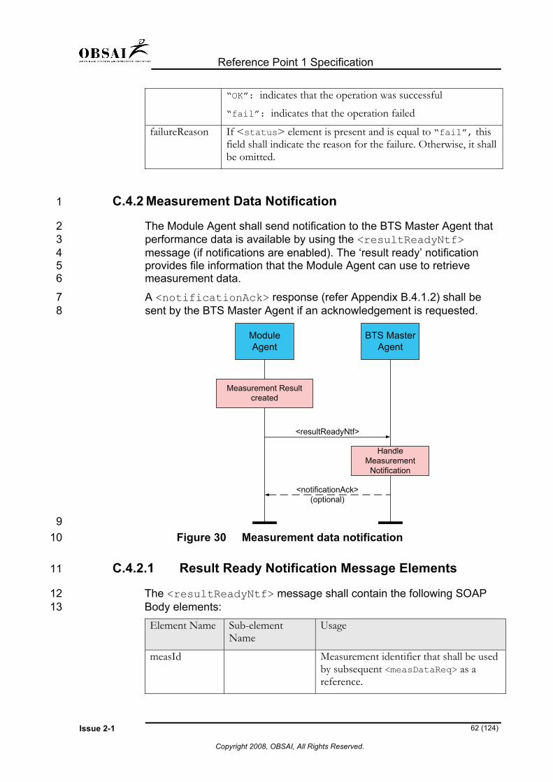
Reference Point 1 Specification
Issue 2-1 62 (124)
Copyright 2008, OBSAI, All Rights Reserved.
“OK”: indicates that the operation was successful
“fail”: indicates that the operation failed
failureReason If <status> element is present and is equal to “fail”, this field shall indicate the reason for the failure. Otherwise, it shall be omitted.
C.4.2 Measurement Data Notification 1
2 3 4 5 6
7 8
The Module Agent shall send notification to the BTS Master Agent that performance data is available by using the <resultReadyNtf> message (if notifications are enabled). The ‘result ready’ notification provides file information that the Module Agent can use to retrieve measurement data.
A <notificationAck> response (refer Appendix B.4.1.2) shall be sent by the BTS Master Agent if an acknowledgement is requested.
Measurement Resultcreated
<resultReadyNtf>
ModuleAgent
BTS MasterAgent
<notificationAck>(optional)
HandleMeasurement
Notification
9 10
11
12 13
Figure 30 Measurement data notification
C.4.2.1 Result Ready Notification Message Elements
The <resultReadyNtf> message shall contain the following SOAP Body elements: Element Name Sub-element
Name Usage
measId Measurement identifier that shall be used by subsequent <measDataReq> as a reference.

Reference Point 1 Specification
Issue 2-1 63 (124)
Copyright 2008, OBSAI, All Rights Reserved.
measSchedule An element of Complex Type containing attributes:
- name: name for the schedule
- replaces: optional element
- function: optional element
This element and its associated sub-elements shall be included when the availability of a scheduled report is being notified.
scheduleItem A sub-element of measurement schedule element. Complex Type containing attributes:
- scheduled: identifier of a schedule item
- priority: optional element
- startTime: time when the measurement shall be started
- stopTime: time when the measurement terminates
fileRetrievallnfo
This element contains file retrieval information.
protocol Indicates the preferred file transfer protocol for retrieving the measurement data:
- “FTP”
- “TFTP”
- “HTTP”
- “SOAP”
userId Optional user Id to be used for measurement retrieval
password Optional password to be used for measurement retrieval
resultURL If the <protocol> is “HTTP”, the URL of the measurement result shall be provided. Otherwise, this element shall not be present in this message.
ipAddress If the protocol is either “FTP” or “TFTP”, the IP Address to open a file transfer session shall be provided. Otherwise, this element shall not be present in this message.

Reference Point 1 Specification
Issue 2-1 64 (124)
Copyright 2008, OBSAI, All Rights Reserved.
fileName If the protocol is either “FTP” or “TFTP”, this element identifies an individual filename including path. Otherwise, this element shall not be present in this message.
format If the protocol is either “FTP” or “TFTP”, this element identifies the file format of the file e.g.3GPP_PM_XML, 3GPP_PM_ASN1...or proprietary. Otherwise, this element shall not be present in this message.
1
2
3 4 5
6 7 8
C.4.3 Request Measurement Data
The BTS Master Agent shall be able to request a Module Agent to send performance data, including parameters and accumulation period, by using the <measDataReq> command.
The Module Agent shall respond with a <measDataRsp> message that contains measurement result data, in XML-format, or the file information necessary for downloading measurement results.
<measDataRsp>
ModuleAgent
BTS MasterAgent
<measDataReq>
CreateMeasurement
Result
HandleMeasurement
Result
9 10 11
12 13 14
Figure 31 Measurement Result exchange, report included in response
When the <measDataRsp> message contains the file information, the Master Agent can retrieve the file using the specified file transfer procedure.
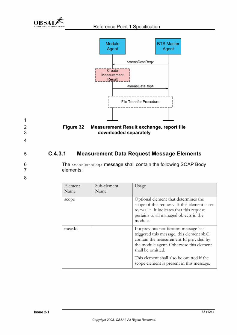
Reference Point 1 Specification
Issue 2-1 65 (124)
Copyright 2008, OBSAI, All Rights Reserved.
<measDataRsp>
ModuleAgent
BTS MasterAgent
<measDataReq>
CreateMeasurement
Result
File Transfer Procedure
1 2 3 4
5
6 7 8
Figure 32 Measurement Result exchange, report file downloaded separately
C.4.3.1 Measurement Data Request Message Elements
The <measDataReq> message shall contain the following SOAP Body elements: Element Name
Sub-element Name
Usage
scope Optional element that determines the scope of this request. If this element is set to “all” it indicates that this request pertains to all managed objects in the module.
measId If a previous notification message has triggered this message, this element shall contain the measurement Id provided by the module agent. Otherwise this element shall be omitted.
This element shall also be omitted if the scope element is present in this message.
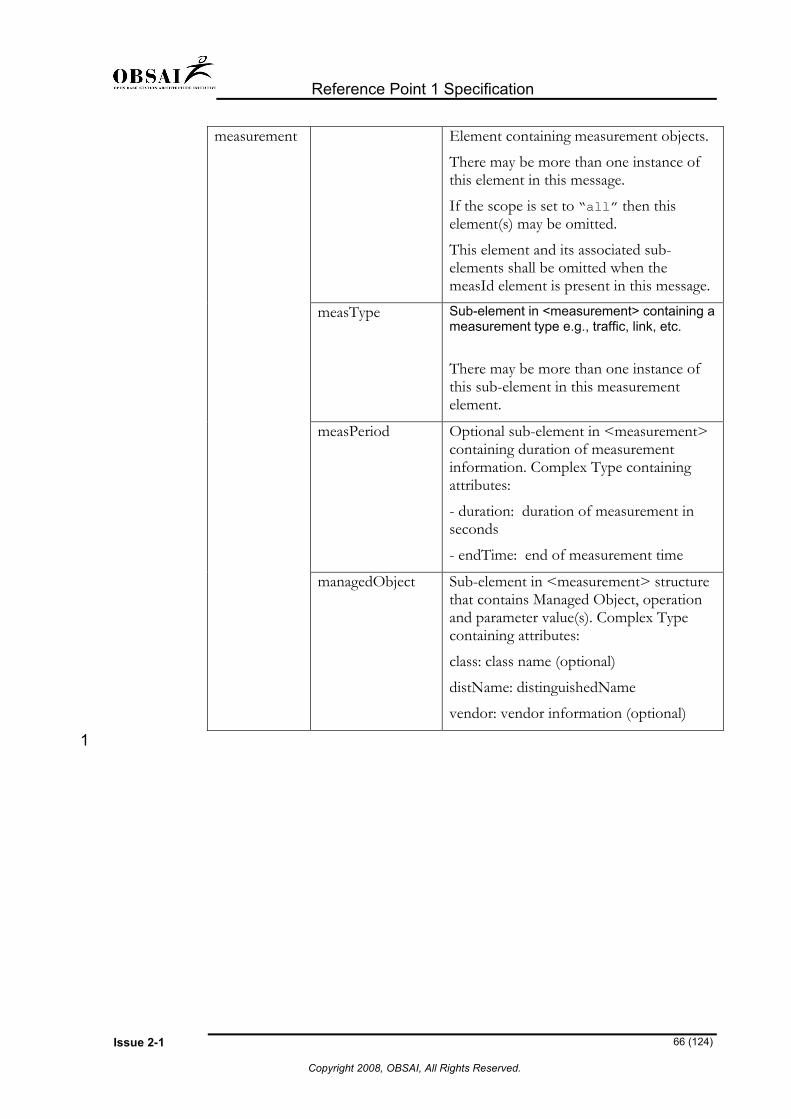
Reference Point 1 Specification
Issue 2-1 66 (124)
Copyright 2008, OBSAI, All Rights Reserved.
measurement Element containing measurement objects.
There may be more than one instance of this element in this message.
If the scope is set to “all” then this element(s) may be omitted.
This element and its associated sub-elements shall be omitted when the measId element is present in this message.
measType
Sub-element in <measurement> containing a measurement type e.g., traffic, link, etc.
There may be more than one instance of this sub-element in this measurement element.
measPeriod
Optional sub-element in <measurement> containing duration of measurement information. Complex Type containing attributes:
- duration: duration of measurement in seconds
- endTime: end of measurement time
managedObject Sub-element in <measurement> structure that contains Managed Object, operation and parameter value(s). Complex Type containing attributes:
class: class name (optional)
distName: distinguishedName
vendor: vendor information (optional)
1

Reference Point 1 Specification
Issue 2-1 67 (124)
Copyright 2008, OBSAI, All Rights Reserved.
C.4.3.2 Measurement Data Response Message Elements 1
2 3
The <measDataRsp> message shall contain following SOAP Body elements: Element Name Sub-element
Name Usage
measId This element shall echo the <measId> specified in the associated measDataReq message.
measurement Element containing measurement objects.
There may be more than one instance of this element in this message. This element and its associated sub-elements shall be omitted if this message contains file retrieval information.
measPeriod Sub-element in <measurement> containing duration of measurement information. Complex Type containing attributes:
- duration: duration of measurement in seconds
- endTime: end of measurement time
measType
Sub-element in <measurement> containing a measurement type e.g., traffic, link, etc.
There may be more than one instance of this sub-element in this measurement element.
managedObject Sub-element in <measurement> structure that contains Managed Object, operation and parameter value(s). Complex Type containing attributes:
class: class name (optional)
distName: distinguishedName
vendor: vendor information (optional)
measValue A sub-element in <measurement> containing the measurement result.
fileRetrievallnfo This element contains file retrieval information. It shall be omitted if <measurement> element is present.

Reference Point 1 Specification
Issue 2-1 68 (124)
Copyright 2008, OBSAI, All Rights Reserved.
protocol
Indicates the preferred file transfer protocol for retrieving the measurement data:
- “FTP”
- “TFTP”
- “HTTP”
- “SOAP”
userId Optional user Id to be used for measurement retrieval
password Optional password to be used for measurement retrieval
resultURL If the <protocol> is “HTTP”, the URL of the measurement result shall be provided. Otherwise, this element shall not be present in this message.
ipAddress If the protocol is either “FTP” or “TFTP”, the IP Address to open a file transfer session shall be provided. Otherwise, this element shall not be present in this message.
fileName If the protocol is either “FTP” or “TFTP”, this element identifies an individual filename including path. Otherwise, this element shall not be present in this message.
format If the protocol is either “FTP” or “TFTP”, this element identifies the file format of the measurement result file e.g.3GPP_PM_XML, 3GPP_PM_ASN1...or proprietary. Otherwise, this element shall not be present in this message.
C.4.4 Create Measurement Schedule 1
2 3
4 5 6
7 8
The BTS Master Agent shall be able to create a measurement schedule for PM data reporting by using the <setScheduleReq> message.
This message shall contain the measurement schedule description e.g. the measured parameters (or measured objects), reporting interval, start time of reports and number of reports.
The Module Agent shall respond with a <setScheduleRsp> message.

Reference Point 1 Specification
Issue 2-1 69 (124)
Copyright 2008, OBSAI, All Rights Reserved.
<setScheduleRsp>
ModuleAgent
BTS MasterAgent
CreateMeasurement
Schedule
<setScheduleReq>
1 2
3
4 5
Figure 33 Schedule Measurement Data Reporting
C.4.4.1 Set Schedule Request Message Elements
The <setScheduleReq> message shall contain the following SOAP Body elements: Element Name Sub-element Name Usage
measSchedule An element of Complex Type containing attributes:
- name (name for the schedule)
- replaces (optional element)
- function (optional element)
There can be more than one instance of this element.
scheduleItem A sub-element of <measSchedule> element. Complex Type containing attributes:
- scheduleId: identifier of a schedule item)
- priority: optional element
- startTime: time when the measurement shall be started
- stopTime: time when the measurement terminates

Reference Point 1 Specification
Issue 2-1 70 (124)
Copyright 2008, OBSAI, All Rights Reserved.
measurement Element containing measurement objects.
There may be more than one instance of this element in this message.
managedObject Sub-element in <measurement> that contains Managed Object, operation and parameter value(s). Complex Type containing attributes:
class: class name (optional)
distName: distinguishedName
vendor: vendor information (optional)
measType
Sub-element in <measurement> containing a measurement type e.g., traffic, link, etc.
There may be more than one instance of this sub-element in this measurement element.
measPeriod Sub-element in <measurement> containing duration of measurement information. Complex Type containing attributes:
- duration: duration of measurement in seconds
- endTime: end of measurement time for the first measurement. This time shall be incremented by <measInterval> for each additional measurement.
measInterval Sub-element of <measurement> containing the time interval between measurements in seconds.
1
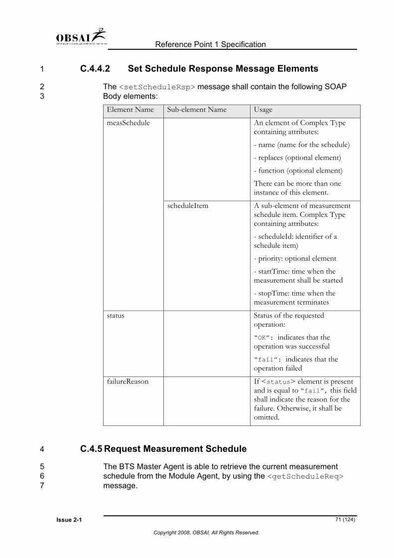
Reference Point 1 Specification
Issue 2-1 71 (124)
Copyright 2008, OBSAI, All Rights Reserved.
C.4.4.2 Set Schedule Response Message Elements 1
2 3
The <setScheduleRsp> message shall contain the following SOAP Body elements: Element Name Sub-element Name Usage
measSchedule An element of Complex Type containing attributes:
- name (name for the schedule)
- replaces (optional element)
- function (optional element)
There can be more than one instance of this element.
scheduleItem
A sub-element of measurement schedule item. Complex Type containing attributes:
- scheduleId: identifier of a schedule item)
- priority: optional element
- startTime: time when the measurement shall be started
- stopTime: time when the measurement terminates
status Status of the requested operation:
“OK”: indicates that the operation was successful
“fail”: indicates that the operation failed
failureReason If <status> element is present and is equal to “fail”, this field shall indicate the reason for the failure. Otherwise, it shall be omitted.
C.4.5 Request Measurement Schedule 4
5 6 7
The BTS Master Agent is able to retrieve the current measurement schedule from the Module Agent, by using the <getScheduleReq> message.

Reference Point 1 Specification
Issue 2-1 72 (124)
Copyright 2008, OBSAI, All Rights Reserved.
The Module Agent responds by sending a <getScheduleRsp> message, that contains a measurement schedule description.
1 2
<getScheduleRsp>
ModuleAgent
BTS MasterAgent
<getScheduleReq>
3 4 5
6
7 8
Figure 34 Retrieve Measurement Data Reporting schedule
C.4.5.1 Get Schedule Request Message Elements
The <getScheduleReq> message shall contain the following SOAP Body elements: Element Name Sub-element Name Usage
scope If this element is set to “all”, the response shall report information of all schedules in the module. If this is used then the <measSchedule> element shall be omitted
measSchedule An element of Complex Type containing attributes:
- name (name for the schedule)
- replaces (optional element)
- function (optional element)

Reference Point 1 Specification
Issue 2-1 73 (124)
Copyright 2008, OBSAI, All Rights Reserved.
scheduleItem A sub-element of measurement schedule item. Complex Type containing attributes:
- scheduleId: identifier of a schedule item)
- priority: optional element
- startTime: time when the measurement shall be started
- stopTime: time when the measurement terminates
C.4.5.2 Get Schedule Response Message Elements 1
2 3
The <getScheduleRsp> message shall contain the following SOAP Body elements: Element Name Sub-element Name Usage
measSchedule An element of Complex Type containing attributes:
- name (name for the schedule)
- replaces (optional element)
- function (optional element)
scheduleItem A sub-element of measurement schedule element. Complex Type containing attributes:
- scheduleId (identifier of a schedule item)
- priority (optional element)
- startTime: time when the measurement shall be started
- stopTime: time when the measurement terminates
measurement Element containing measurement objects.
There may be more than one instance of this element in this message.

Reference Point 1 Specification
Issue 2-1 74 (124)
Copyright 2008, OBSAI, All Rights Reserved.
managedObject Sub-element in <measurement> that contains Managed Object, operation and parameter value(s). Complex Type containing attributes:
class: class name (optional)
distName: distinguishedName
vendor: vendor information (optional)
measType
Sub-element in <measurement> containing a measurement type e.g., traffic, link, etc.
There may be more than one instance of this sub-element in this measurement element.
measPeriod Sub-element in <measurement> containing duration of measurement information. Complex Type containing attributes:
- duration: duration of measurement in seconds
- endTime: end of measurement time for the first measurement.
measInterval Sub-element of <measurement> containing the time interval between measurements in seconds.
C.4.6 Control Measurement Data reporting 1
2
3 4
C.4.6.1 Activate Measurement Data Reporting:
The BTS Master Agent shall be able to start/activate performance data reporting by using the <controlScheduleReq> message.

Reference Point 1 Specification
Issue 2-1 75 (124)
Copyright 2008, OBSAI, All Rights Reserved.
<controlScheduleRsp>
ModuleAgent
BTS MasterAgent
ActivateMeasurement Job
<controlScheduleReq> {activate}
MeasurementSchedule Created
MeasurementResult Ready
<measDataRsp>
1 2
3
4 5
6 7 8 9
10
11 12 13
14 15
Figure 35 Activate Measurement Data Reporting The Module Agent responds with <controlScheduleRsp> message.
When the measurements pertaining to an active schedule are available, the Module Agent shall be able to send:
a) <measDataRsp> message asynchronously to the BTS Master Agent.
b) Notification that measurement data is available by using the <resultReadyNtf> message.
C.4.6.2 Suspend Measurement Data Reporting:
The BTS Master Agent shall be able to stop/suspend the reporting of performance data by using the <controlScheduleReq> message with the operation “suspend”.
The Module Agent responds with a <controlScheduleRsp> message.

Reference Point 1 Specification
Issue 2-1 76 (124)
Copyright 2008, OBSAI, All Rights Reserved.
<controlScheduleRsp>
ModuleAgent
BTS MasterAgent
SuspendMeasurement Job
<controlScheduleReq> {suspend}
MeasurementSchedule created
and activated
1 2
3
4 5
Figure 36 Suspend Measurement Data Reporting
C.4.6.3 Control Schedule Request Message Elements
The <controlScheduleReq> message shall contain the following SOAP Body elements: Element Name Sub-element Name Usage
operation Operation identifier element for measurement control:
“activate”: activate the schedule
“suspend”: suspend the schedule
“remove”: remove the schedule
“stateReq”: request the state of a schedule
measSchedule An element of Complex Type containing attributes:
- name (name for the schedule)
- replaces (optional element)
- function (optional element)

Reference Point 1 Specification
Issue 2-1 77 (124)
Copyright 2008, OBSAI, All Rights Reserved.
scheduleItem A sub-element of measurement schedule element. Complex Type containing attributes:
- scheduleId (identifier of a schedule item)
- priority (optional element)
- startTime: time when the measurement shall be started
- stopTime: time when the measurement terminates
C.4.6.4 Control Schedule Response Message Elements 1
2 3
The <controlScheduleRsp> message shall contain the following SOAP Body elements: Element Name Sub-element Name Usage
measSchedule An element of Complex Type containing attributes:
- name: name for the schedule
- replaces: optional element
- function: optional element
scheduleItem A sub-element of measurement schedule element. Complex Type containing attributes:
- scheduleId: identifier of a schedule item
- priority: optional element
- startTime: time when the measurement shall be started
- stopTime: time when the measurement terminates
operation This element indicates the requested operation:
“activate”: activate the schedule
“suspend”: suspend the schedule
“remove”: remove the

Reference Point 1 Specification
Issue 2-1 78 (124)
Copyright 2008, OBSAI, All Rights Reserved.
schedule
“stateReq”: request the state of a schedule
operationStatus If the controlScheduleReq operation was “stateReq”, then this element shall have one of the following values:
“active”: indicates that the schedule was activated
“suspended”: indicates that the schedule
“invalid”: indicates that the requested schedule is invalid
If the controlScheduleReq operation was “activate”, “suspend” or “remove”, then this element shall have one of the following values:
“OK”: indicates that the operation was successful
“fail”: indicates that the operation failed
failureReason If <operationStatus> element is present and is equal to “fail”, this field shall indicate the reason for the failure. Otherwise, it shall be omitted.
C.4.7 Modify Measurement Attributes 1
2 3 4 5
6 7
The BTS Master Agent shall be able to modify measurement attributes (e.g. parameters to be monitored, type of threshold, threshold value, data reporting mode, and starting time) by using the <setMeasAttributesReq> message.
The Module Agent shall respond with a <setMeasAttributesRsp> message that contains new attribute designations.
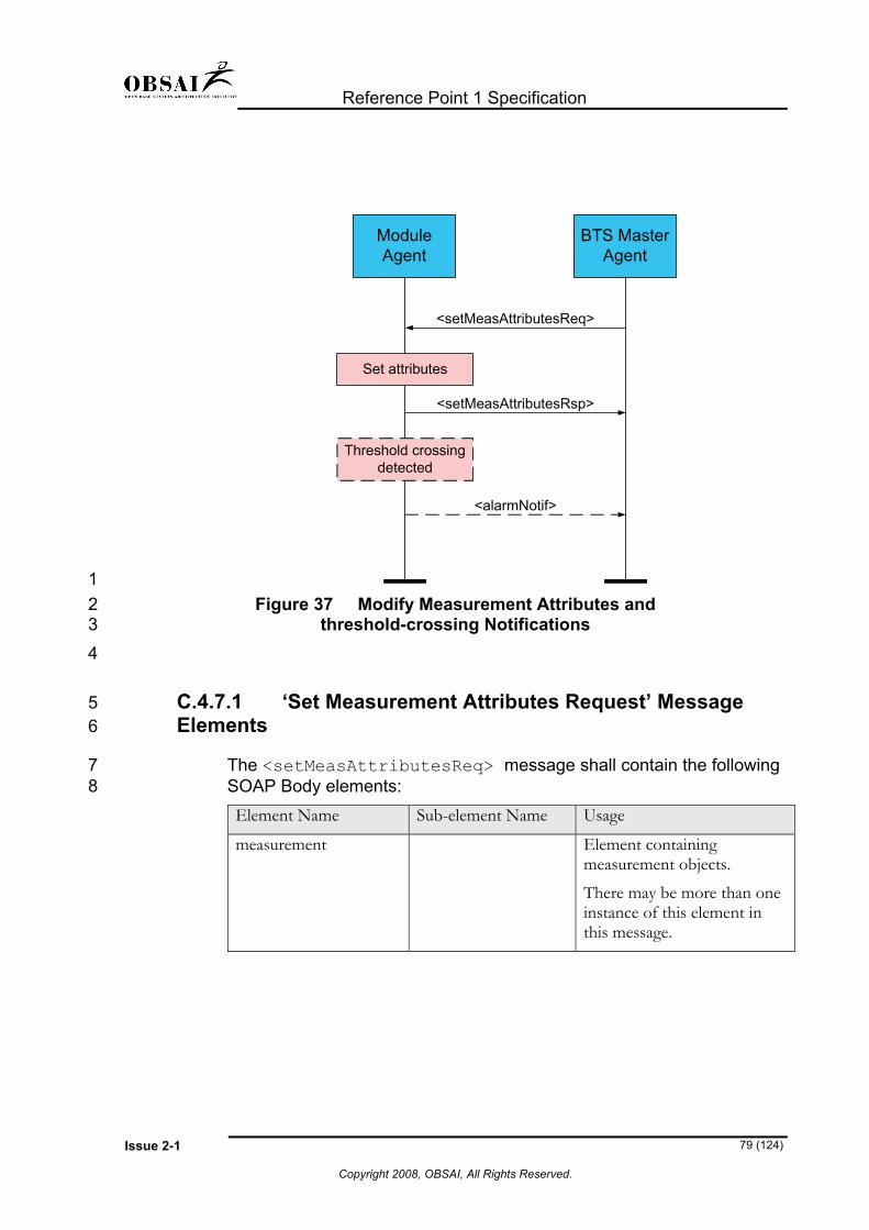
Reference Point 1 Specification
Issue 2-1 79 (124)
Copyright 2008, OBSAI, All Rights Reserved.
<setMeasAttributesRsp>
ModuleAgent
BTS MasterAgent
Set attributes
<setMeasAttributesReq>
Threshold crossingdetected
<alarmNotif>
1 2 3 4
5 6
7 8
Figure 37 Modify Measurement Attributes and threshold-crossing Notifications
C.4.7.1 ‘Set Measurement Attributes Request’ Message Elements
The <setMeasAttributesReq> message shall contain the following SOAP Body elements: Element Name Sub-element Name Usage
measurement Element containing measurement objects.
There may be more than one instance of this element in this message.

Reference Point 1 Specification
Issue 2-1 80 (124)
Copyright 2008, OBSAI, All Rights Reserved.
measType
Sub-element in <measurement> containing a measurement type e.g., traffic, link, etc.
There may be more than one instance of this sub-element in this measurement element.
managedObject Sub-element in <measurement> that contains Managed Object, operation and parameter value(s). Complex Type containing attributes:
class: class name (optional)
distName: distinguishedName
vendor: vendor information (optional)
newAttributeValues Element containing new attribute value(s) for the given parameter of Complex Type.
1
2 3
4 5
C.4.7.2 ’Set Measurement Attributes Response’ Message Elements
The <setMeasAttributesRsp> message shall contain the following SOAP Body elements: Element Name Sub-element Name Usage
measurement Element containing measurement objects.
There may be more than one instance of this element in this message.

Reference Point 1 Specification
Issue 2-1 81 (124)
Copyright 2008, OBSAI, All Rights Reserved.
measType Sub-element in <measurement> containing a measurement type e.g., traffic, link, etc.
There may be more than one instance of this sub-element in this measurement element.
managedObject Sub-element in <measurement> that contains Managed Object, operation and parameter value(s). Complex Type containing attributes:
class: class name (optional)
distName: distinguishedName
vendor: vendor information (optional)
newAttributeValues Element containing new attribute value(s) for the given parameter of Complex Type.
oldAttributeValues Element containing previous attribute value(s) for the given parameter of Complex Type.
status Status of the requested operation:
“OK”: indicates that the operation was successful
“fail”: indicates that the operation failed
failureReason If <status> element is present and is equal to “fail”, this field shall indicate the reason for the failure. Otherwise, it shall be omitted.
C.4.8 Retrieve Measurement Attributes 1
2 3 4
The BTS Master Agent shall be able to retrieve the current measurement attributes by using <getMeasAttributesReq> command.

Reference Point 1 Specification
Issue 2-1 82 (124)
Copyright 2008, OBSAI, All Rights Reserved.
The Module Agent shall respond with a <getMeasAttributesRsp> message.
1 2
<getMeasAttributesRsp>
ModuleAgent
BTS MasterAgent
Create report ofcurrent attributes
<getMeasAttributesReq>
3 4
5 6
7 8
Figure 38 Requesting Measurement Attributes
C.4.8.1 ‘Get Measurement Attributes Request’ Message Elements
The <getMeasAttributesReq> message shall contain the following SOAP Body elements: Element Name Sub-element Name Usage
measurement Element containing measurement objects.
There may be more than one instance of this element in this message.
measType Sub-element in <measurement> containing a measurement type e.g., traffic, link, etc.
There may be more than one instance of this sub-element in this measurement element.

Reference Point 1 Specification
Issue 2-1 83 (124)
Copyright 2008, OBSAI, All Rights Reserved.
managedObject Sub-element in <measurement> that contains Managed Object, operation and parameter value(s). Complex Type containing attributes:
class: class name (optional)
distName: distinguishedName
vendor: vendor information (optional)
measAttribute Element containing requested attribute for a managed object. There may be more than one instance of this element.
C.4.8.2 ‘Get Measurement Attributes Response’ Message Elements
1 2
3 4
ThegetMeasAttributesRsp> message shall contain the following SOAP Body elements: Element Name Sub-element Name Usage
measurement Element containing measurement objects.
There may be more than one instance of this element in this message.
measType
Sub-element in <measurement> containing a measurement type e.g., traffic, link, etc.
There may be more than one instance of this sub-element in this measurement element.

Reference Point 1 Specification
Issue 2-1 84 (124)
Copyright 2008, OBSAI, All Rights Reserved.
managedObject Sub-element in <measurement> that contains Managed Object, operation and parameter value(s). Complex Type containing attributes:
class: class name (optional)
distName: distinguishedName
vendor: vendor information (optional)
newAttributeValues Element containing new attribute value(s) for the requested attributes.
oldAttributeValues Element containing previous attribute value(s) for the requested attributes.
1 2
3
4 5 6 7 8
9
10 11 12 13 14
Appendix D Configuration Management This appendix specifies the Configuration Management (CM) part of the OAM&P interface at RP1. In the realm of OBSAI, Configuration Management covers the following CM functions:
• Module Configuration Management
• Resource State Control The concepts for these are presented and the corresponding SOAP message structures are defined. However, the document does not contain a complete set of attributes that must be implemented. It is assumed that the reader is familiar with the general concepts of XML and SOAP as defined by W3C® (http://www.w3c.org). 15
16 17 18
The configuration management functionality in the Module Agent shall fulfill the specified requirements in order to be compliant with this specification.

Reference Point 1 Specification
Issue 2-1 85 (124)
Copyright 2008, OBSAI, All Rights Reserved.
D.1 Version and history 1
2 3 4 5 6
The following table shall contain the version information associated with the CM aspect of OBSAI OAM&P specifications. This version information shall be used in the <version> element in the header of all CM messages.
Version number Release information 1.0 First release of CM
Future release • Changed the element name filename to fileName in this appendix.
• Added operation to create and delete managed object in C.4.5.1
7
8
9 10 11 12 13 14 15 16
17
18
19 20 21
22
23
D.2 Specific CM Definitions Resource: Physical or logical entity that is subject to system management. ITU-T X.730 recommends representing each resource in a system by a managed object. Module: Physical entity (Hardware) that implements a logical BTS Block. State: The management state of the managed object represents the instantaneous condition of availability and operability of the associated resource from the management point of view.
D.3 Configuration Management Concepts
D.3.1 Module Configuration Management
The BTS Master Agent is responsible for managing parameters in other modules by using CM messages specified in this document. The Master Agent shall be able to:
• Set parameter(s) on any module
• Retrieve parameter(s) from any module

Reference Point 1 Specification
Issue 2-1 86 (124)
Copyright 2008, OBSAI, All Rights Reserved.
• Receive ‘parameter value changed’ notifications from any module
1 2 3 4
5
6
7
8
9 10 11 12 13
14
15 16
17
18 19 20
All supported parameters for module configuration shall be described in the Module Property File by the module vendor.
D.3.2 Resource State Control
The Master Agent shall be able to:
• Change resource state(s) on any module
• Retrieve the current state of a resource on any module
• Receive ‘state changed’ notifications from any module The recommended administrative and operational states of the resources are defined in [ITU-T X.731]. It shall be possible to issue the resource state control commands to one or more resources at a time.
D.4 CM Messages This section describes the various CM operations specified by OBSAI.
D.4.1 Module Ready Indication and Acknowledge
The BTS Master and Module Agents perform auto-detection by monitoring for the <moduleReadyInd> messages. This enables the master agent and other modules to monitor each other’s availability.

Reference Point 1 Specification
Issue 2-1 87 (124)
Copyright 2008, OBSAI, All Rights Reserved.
BTS MasterAgent (CCM)
ModuleAgent
<moduleReadyAck> {Module Logical Name}(unicasted)
Module Start-up
<moduleReadyInd> {Module Info}
Module detectedand accepted
<moduleReadyInd> {Module Info}
. . .
<moduleReadyInd> {Module Info}
1 2 3
4 5 6 7 8 9
10 11 12 13 14
15 16 17
Figure 39 Module Ready Indication in the module start-up
The very first <moduleReadyInd> message that is sent to the master agent shall be used for registering the basic module information to the BTS Master Agent. Based on the received information, the BTS Master Agent is able to decide if a module can be integrated into the system. When the BTS Master Agent accepts a module into the system, it shall reply with a unicast <moduleReadyAck> message to a module that contains a Module Identifier (“Logical ID”), for a module in the <to> element of the SOAP message header and other parameters in the message body, e.g. keep-alive polling period. A BTS module shall store the received Module Identifier in order to use it in subsequent messages to the master agent and when registering its services.
In case no <moduleReadyAck> is received from the BTS Master Agent, a module shall repeat the <moduleReadyInd> messages at a configured interval (seconds), until the BTS Master Agent replies.

Reference Point 1 Specification
Issue 2-1 88 (124)
Copyright 2008, OBSAI, All Rights Reserved.
BTS MasterAgent (CCM)
moduleReadyInd {All Nodes}(multicasted)
Module Startup
Module Ready Indication in the module start-up
ModuleAgent
moduleReadyInd {All Nodes}(multicasted)
moduleReadyInd {All Nodes}(multicasted)
.
.
.Module Startup
moduleReadyInd {All Nodes}(multicasted)
moduleReadyInd {All Nodes}(multicasted)
moduleReadyInd(unicasted)
moduleReadyInd(unicasted)
Join to a multicastgroup
.
.
moduleReadyInd {All Nodes}(multicasted)
.
. 1
2 3 4 5 6
7 8 9
10
Figure 40 Module Ready Indication keep-alive polling
When the BTS Master Agent has detected and accepted a module (see Figure 39 ), the Module Agent shall start sending the <moduleReadyInd> messages at configured intervals.
The BTS Master Agent shall send <moduleReadyInd> messages at configured intervals to the modules that have registered their Auto Detection service. This <moduleReadyInd> sent by the master agent may be sent in one of the following two ways:

Reference Point 1 Specification
Issue 2-1 89 (124)
Copyright 2008, OBSAI, All Rights Reserved.
1. Multicasting to “all-nodes” group (IPv6) and/or all-hosts” group (IPv4), or to a given link-local group. This requires each module to join a given multicast group for monitoring <moduleReadyInd> messages from the master agent.
1 2 3 4
5 6 7 8
10
11 12
2. Synchronously unicasting to all modules. If this method is used, the BTS Master Agent shall omit the multicast group address parameter in the <moduleReadyAck> message that is sent to a newly inserted module.
D.4.1.1 Module Ready Indication and Acknowledge message 9 elements
The first <moduleReadyInd> message sent from a module to the master agent shall contain the following SOAP Body elements: Element Name Usage
moduleType This element is used to convey the type of the BTS Module to the master agent in the first <moduleReadyInd> message sent. This element may be omitted in subsequent messages
vendor Name of the module vendor. May be omitted after the first message is accepted by the master agent.
productCode Manufacturer specific Product Code of the module.
May be omitted after the first message is accepted by the master agent.
serialNum Serial Number of the module.
May be omitted after the first message is accepted by the master agent.
rack Optional module position information indicating the rack in which the module is installed.
May be omitted after the first message is accepted by the master agent.
subRack Optional module position information indicating the subrack in which the module is installed.
May be omitted after the first message is accepted by the master agent.
slot Optional module position information indicating the slot in which the module is installed.
May be omitted after the first message is accepted by the master agent.
bldVersion Element to convey the active software load version.

Reference Point 1 Specification
Issue 2-1 90 (124)
Copyright 2008, OBSAI, All Rights Reserved.
restartCause Indicates cause for the latest module restart: “power_on”
“watchdog” – software failure detected by hardware watchdog logic
“SW_failure” – software failure detected by software
“management” - Restart initiated by external or internal management functions
<other> - any other failure e.g., “unknown”
This element may be omitted after the first successful moduleReadyInd message is accepted by the master agent.
timerValue This element conveys the keep-alive polling timer value in seconds.
When this message originates from the CCM, this element shall convey a new value for this time.
When this message originates from a module, this element is used to echo the latest timer value.
This element may be omitted after the first successful moduleReadyInd message is accepted by the master agent.
multiCastGroup This element is present only in messages originating from the master agent. It indicates the Multicast Group address to which the master agent shall send its <moduleReadyInd>.
This element shall be omitted when the CCM is configured to send synchronously unicast <moduleReadyInd> messages.
1
2 3 4 5 6 7 8 9
10
11 12
In the first <moduleReadyInd> message sent by the module, the <From> element of the SOAP Header shall be empty indicating that it has not yet received its Module Identifier (as will be the case for a newly inserted module) from the BTS Master Agent. Once a module insertion has been accepted and acknowledged by the master agent, subsequent <moduleReadyInd> messages sent from that module may have several of the elements omitted as shown in the table above. The <from> element in the header shall have the Module Identifier assigned to it by the master agent.
The <moduleReadyAck> message is unicast by the master agent to the module in response to the module’s first successful

Reference Point 1 Specification
Issue 2-1 91 (124)
Copyright 2008, OBSAI, All Rights Reserved.
<moduleReadyInd> message. The elements of <moduleReadyAck> message are as shown below:
1 2
Element Name Usage
moduleType This element is used to echo the type of the BTS Module that the master agent is acknowledging.
serialNum This element is used to echo the serial number of the BTS Module that the master agent is acknowledging.
timerValue This element conveys the keep-alive polling timer value in seconds assigned to the module by the master agent.
moduleId An element containing a logical Module Identifier assigned to a module by the master agent.
multiCastGroup This element indicates the Multicast Group address to which the master agent shall send its <moduleReadyInd>.
This element shall be omitted when the master agent is configured to send synchronously unicast <moduleReadyInd> messages.
D.4.2 Modify Resource State 3
4 5 6
7 8 9
The BTS Master Agent shall be able to modify resource states (e.g. activate, block, unblock, shutdown, restart) using the <modifyStateReq> message.
When resource state(s) is/are changed, the Module Agent shall send a <stateChangeInd> message (see D.4.3) to all clients that have subscribed to such state change notifications.

Reference Point 1 Specification
Issue 2-1 92 (124)
Copyright 2008, OBSAI, All Rights Reserved.
BTS MasterAgent
ModuleAgent
<modifyStateReq>
<stateChangeInd>
Modify ResourceState(s)
Resource State(s)changed
1 2 3
4
5 6
Figure 41 Modify Resource State
D.4.2.1 Modify Resource State Message Elements
The <modifyStateReq> message shall contain the following SOAP Body elements: Element Name Sub-element Name Usage
managedObject Element that contains Managed Object). Complex Type containing attributes:
class: class name (optional)
distName: distinguishedName
vendor: vendor information (optional)
stateType The state attribute type of the managed object
newState New state of the specified attribute of the managed object.

Reference Point 1 Specification
Issue 2-1 93 (124)
Copyright 2008, OBSAI, All Rights Reserved.
D.4.3 Resource State Changed Indication 1
2 3 4 5 6
The <stateChangeInd> message shall be used by the Module Agent for communicating resource state changes to the Master Agent and optionally to other clients that have subscribed to state change notifications.
BTS MasterAgent
ModuleAgent
Resource Statechanged
<stateChangeInd>
7 8 9
10
11 12
Figure 42 Resource State Changed Indication
D.4.3.1 State Change Indication Message Elements
The <stateChangeInd> message shall contain the following SOAP Body elements: Element Name Sub-element Name Usage
managedObject Element that contains Managed Object. Complex Type containing attributes:
class: class name (optional)
distName: distinguishedName
vendor: vendor information (optional)
stateType Indicates the reported state attribute type of the Managed Object
newState New state of the Managed Object

Reference Point 1 Specification
Issue 2-1 94 (124)
Copyright 2008, OBSAI, All Rights Reserved.
prevState Old state of the Managed Object
source Indicates the cause of the operation that led to this notification:
“resource“: state changed by a resource on the module
“management”: state changed by management functions
<other>: other reasons e.g., “unknown”
status If the <source> is equal to “management”, then this element shall indicate the status of the operation:
“OK”: indicates that the operation was successful
“fail”: indicates that the operation failed
failureReason If <status> element is present and is equal to “fail”, this field shall indicate the reason for the failure. Otherwise, it shall be omitted.
1
2
3 4 5
6 7 8
D.4.4 Retrieve Resource State
The BTS Master Agent shall be able to request the operational/administrative state of a module, or a resource within a module, using the <resourceStateReq> message.
The Module Agent shall respond with a <resourceStateRsp> message that contains the state(s) of the requested resource(s).

Reference Point 1 Specification
Issue 2-1 95 (124)
Copyright 2008, OBSAI, All Rights Reserved.
BTS MasterAgent
ModuleAgent
<resourceStateRsp>
<resourceStateReq>
1 2 3
4
5 6
Figure 43 Retrieve Resource State
D.4.4.1 Retrieve Resource State Message Elements
The <resourceStateReq> message shall contain the following SOAP Body elements: Element Name Sub-element Name Usage
managedObject Element that contains Managed Object). Complex Type containing attributes:
class: class name (optional)
distName: distinguishedName
vendor: vendor information (optional)
stateType Indicates the requested state attribute type of the managed object
7
8 9
The corresponding reply message <resourceStateRsp> shall contain the following SOAP Body elements: Element Name Sub-element Name Usage

Reference Point 1 Specification
Issue 2-1 96 (124)
Copyright 2008, OBSAI, All Rights Reserved.
managedObject Element that contains Managed Object. Complex Type containing attributes:
class: class name (optional)
distName: distinguishedName
vendor: vendor information (optional)
stateType Indicates the reported state attribute type of the Managed Object
newState New state of the Managed Object
prevState Old state of the Managed Object
source Indicates the cause of the operation that led to this notification:
“resource“: state changed by a resource on the module
“management”: state changed by management functions
<other>: other reasons e.g., “unknown”
status If the <source> is equal to “management”, then this element shall indicate the status of the operation:
“OK”: indicates that the operation was successful
“fail”: indicates that the operation failed
failureReason If <status> element is present and is equal to “fail”, this field shall indicate the reason for the failure. Otherwise, it shall be omitted.

Reference Point 1 Specification
Issue 2-1 97 (124)
Copyright 2008, OBSAI, All Rights Reserved.
D.4.5 Modify Parameters 1
2 3 4 5 6 7 8
The BTS Master Agent shall be able to configure module parameters with the <modifyParameterReq> message that contains the parameter values to be set into the module. When parameter(s) is/are changed, the Module Agent shall send a <parValueChangeInd> message (see D.4.6) that may be sent to all clients that have subscribed to parameter change notifications.
BTS MasterAgent
ModuleAgent
<modifyParameterReq>
<parValueChangeInd>
Modify Parameter(s)
Parameter value(s)changed
9 10 11
12
13 14 15
Figure 44 Modify Parameters Request
D.4.5.1 Modify Parameters Request Message Elements
The <modifyParameterReq> message shall contain the following SOAP Body elements: Element Name Sub-element
Name Usage

Reference Point 1 Specification
Issue 2-1 98 (124)
Copyright 2008, OBSAI, All Rights Reserved.
fileRetrievalInfo This element contains file retrieval information. If this is specified then the <managedObject> element and its associated sub-elements are omitted.
protocol
Indicates the preferred file transfer protocol for retrieving the measurement data:
- “FTP”
- “TFTP”
- “HTTP”
- “SOAP”
userId Optional user Id to be used for file retrieval.
password Optional password to be used for file retrieval.
fileURL If the <protocol> is “HTTP”, the URL of the bulk data file shall be provided. Otherwise, this element shall not be present in this message.
ipAddress If the protocol is either “FTP” or “TFTP”, the IP Address to open a file transfer session shall be provided. Otherwise, this element shall not be present in this message.
fileName If the protocol is either “FTP” or “TFTP”, this element identifies an individual filename including path. Otherwise, this element shall not be present in this message.

Reference Point 1 Specification
Issue 2-1 99 (124)
Copyright 2008, OBSAI, All Rights Reserved.
format If the protocol is either “FTP” or “TFTP”, this element identifies the file format of the bulk data file e.g.3GPP_PM_XML, 3GPP_PM_ASN1...or proprietary. Otherwise, this element shall not be present in this message.
managedObject If <fileRetrievalInfo> is not specified, this element shall contain the Managed Object element of Complex Type containing attributes:
- class (optional)
- distName: distinguished name
- vendor (optional)
There may be more than one instance of this element in this message
operation Sub-element of <managedObject> that indicates the requested activity targeted on the Managed Object.
“create_mo”: instantiate a managed object of the given class with the given distinguished name
“create_parm”: instantiate the specified parameter
“update_parm”: update the specified parameter(s)
“delete_mo”: delete this managed object.
“delete_parm”: delete the specified parameter.
parameter This sub-element of <managedObject> of Complex Type containing sub-elements:
- parameter name
- newValue
- prevValue
There may be multiple instances of this sub-element in <managedObject>.

Reference Point 1 Specification
Issue 2-1 100 (124)
Copyright 2008, OBSAI, All Rights Reserved.
D.4.6 Parameter Value Changed Indication 1
2 3 4 5
The Module Agent shall use <parValueChangeInd> message for communicating parameter value changes to the Master Agent and to other clients that have subscribed parameter change notifications.
BTS MasterAgent
ModuleAgent
Parameter Valuechanged
<parValueChangeInd>
6
7
8
9 10
11 12 13
Figure 45 Parameter Value Changed Indication
D.4.6.1 Parameter Value Change Indication Message Elements
The <parValueChangeInd> message shall contain the following SOAP Body elements: Element Name Sub-element Name Usage

Reference Point 1 Specification
Issue 2-1 101 (124)
Copyright 2008, OBSAI, All Rights Reserved.
managedObject
This element shall contain the Managed Object element of Complex Type containing attributes:
- class (optional)
- distName: distinguished name
- vendor (optional)
There may be more than one instance of this element in this message
parameter This sub-element of <managedObject> of Complex Type containing sub-elements:
- parameter name
- newValue
- prevValue
There may be multiple instances of this sub-element in <managedObject>..
source Indicates the cause of the operation that led to this notification:
“resource“: state changed by a resource on the module
“management”: state changed by management functions
<other>: other reasons e.g., “unknown”
status If the <source> is equal to “management”, then this element shall indicate the status of the operation:
“OK”: indicates that the schedule was set successfully
“fail”: indicates failure
failureReason If <status> element is present and is equal to “fail”, this field shall
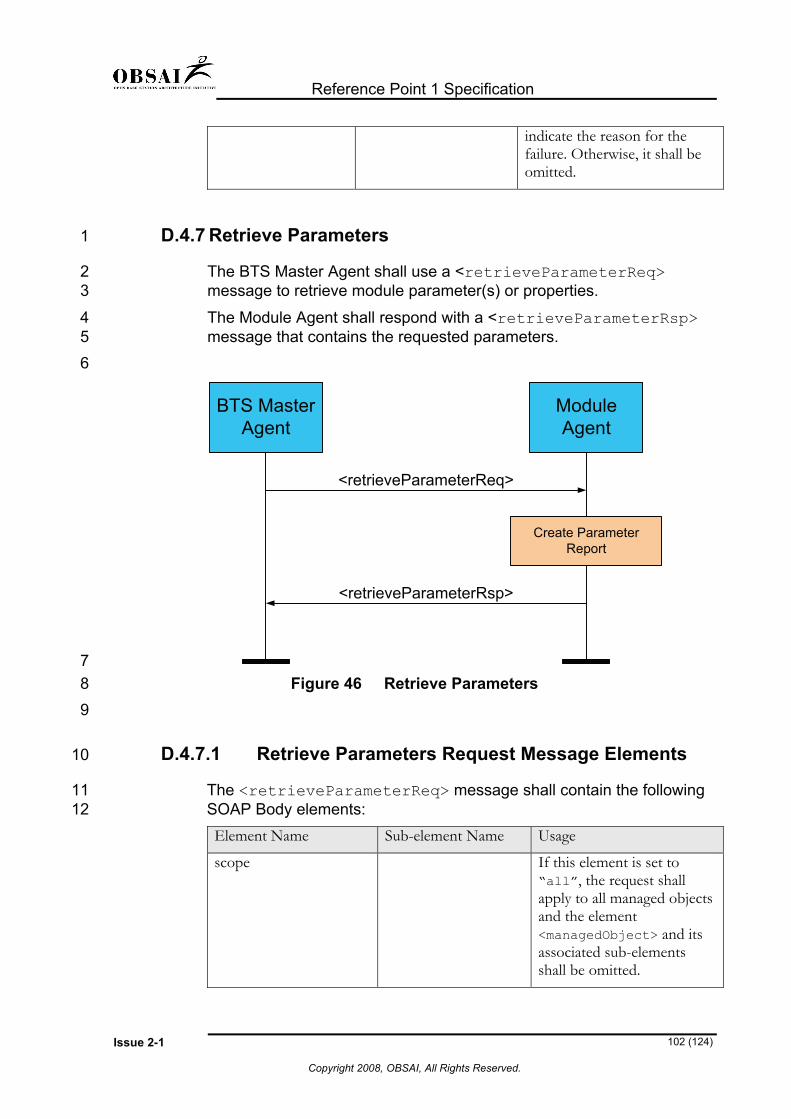
Reference Point 1 Specification
Issue 2-1 102 (124)
Copyright 2008, OBSAI, All Rights Reserved.
indicate the reason for the failure. Otherwise, it shall be omitted.
D.4.7 Retrieve Parameters 1
2 3
4 5 6
The BTS Master Agent shall use a <retrieveParameterReq> message to retrieve module parameter(s) or properties.
The Module Agent shall respond with a <retrieveParameterRsp> message that contains the requested parameters.
BTS MasterAgent
ModuleAgent
<retrieveParameterReq>
<retrieveParameterRsp>
Create ParameterReport
7 8 9
10
11 12
Figure 46 Retrieve Parameters
D.4.7.1 Retrieve Parameters Request Message Elements
The <retrieveParameterReq> message shall contain the following SOAP Body elements: Element Name Sub-element Name Usage
scope If this element is set to “all”, the request shall apply to all managed objects and the element <managedObject> and its associated sub-elements shall be omitted.

Reference Point 1 Specification
Issue 2-1 103 (124)
Copyright 2008, OBSAI, All Rights Reserved.
managedObject This element contains the Managed Object and requested parameter types. Complex Type containing attributes:
- class (optional)
- distName
- vendor (optional)
There may be more than one instance of <managedObject> and its associated sub-elements in this message.
parameter This sub-element of <managedObject> of Complex Type containing sub-elements:
- parameter name
- newValue
- prevValue
There may be multiple instances of this sub-element in <managedObject>.
1
2 3
The corresponding reply message <retrieveParameterRsp> shall contain the following SOAP Body elements: Element Name Sub-element
Name Usage
fileRetrievalInfo This element contains file retrieval information. If this is specified, <managedObject> element and its associated sub-elements shall be omitted.

Reference Point 1 Specification
Issue 2-1 104 (124)
Copyright 2008, OBSAI, All Rights Reserved.
protocol
Indicates the preferred file transfer protocol for retrieving the measurement data:
- “FTP”
- “TFTP”
- “HTTP”
- “SOAP”
userId Optional user Id to be used for file retrieval.
password Optional password to be used for file retrieval.
fileURL If the <protocol> is “HTTP”, the URL of the bulk data file shall be provided. Otherwise, this element shall not be present in this message.
ipAddress If the protocol is either “FTP” or “TFTP”, the IP Address to open a file transfer session shall be provided. Otherwise, this element shall not be present in this message.
fileName If the protocol is either “FTP” or “TFTP”, this element identifies an individual filename including path. Otherwise, this element shall not be present in this message.
format If the protocol is either “FTP” or “TFTP”, this element identifies the file format of the bulk data file e.g.3GPP_PM_XML, 3GPP_PM_ASN1...or proprietary. Otherwise, this element shall not be present in this message.
managedObject If <fileRetrievalInfo> is not specified, this element shall contain the Managed Object element of Complex Type containing attributes:
- class (optional)
- distName: distinguished name
- vendor (optional)
There may be more than one instance of this element in this message

Reference Point 1 Specification
Issue 2-1 105 (124)
Copyright 2008, OBSAI, All Rights Reserved.
parameter This sub-element of <managedObject> of Complex Type containing sub-elements:
- parameter name
- newValue
- prevValue
There may be multiple instances of this sub-element in <managedObject>.
1
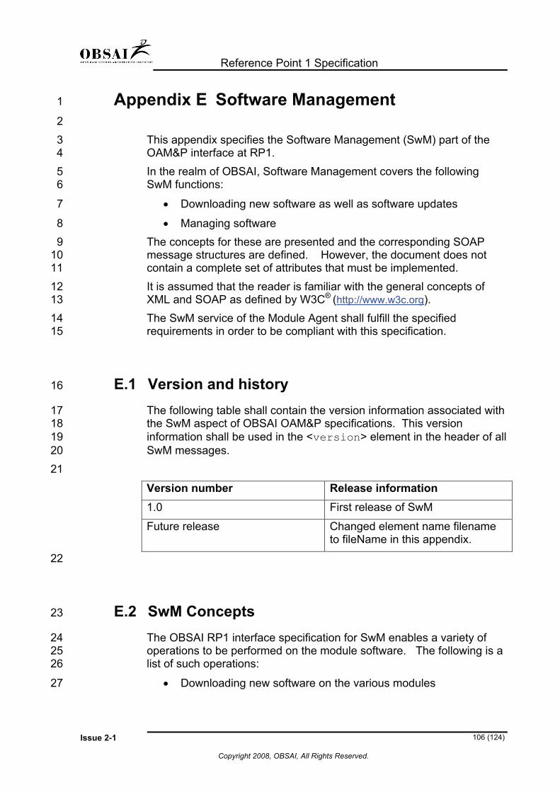
Reference Point 1 Specification
Issue 2-1 106 (124)
Copyright 2008, OBSAI, All Rights Reserved.
Appendix E Software Management 1
2 3 4 5 6
7
8 9
10 11 12
This appendix specifies the Software Management (SwM) part of the OAM&P interface at RP1. In the realm of OBSAI, Software Management covers the following SwM functions:
• Downloading new software as well as software updates
• Managing software The concepts for these are presented and the corresponding SOAP message structures are defined. However, the document does not contain a complete set of attributes that must be implemented. It is assumed that the reader is familiar with the general concepts of XML and SOAP as defined by W3C® (http://www.w3c.org). 13
14 15
16
17 18 19 20 21
The SwM service of the Module Agent shall fulfill the specified requirements in order to be compliant with this specification.
E.1 Version and history The following table shall contain the version information associated with the SwM aspect of OBSAI OAM&P specifications. This version information shall be used in the <version> element in the header of all SwM messages.
Version number Release information 1.0 First release of SwM
Future release Changed element name filename to fileName in this appendix.
22
23
24 25 26
27
E.2 SwM Concepts The OBSAI RP1 interface specification for SwM enables a variety of operations to be performed on the module software. The following is a list of such operations:
• Downloading new software on the various modules

Reference Point 1 Specification
Issue 2-1 107 (124)
Copyright 2008, OBSAI, All Rights Reserved.
• Downloading updates to the existing software load on the various modules
1 2
3 4 5 6 7 8 9
10
11
12
13
14 15 16 17 18 19 20 21
22
• Managing the software on the various modules o Request version and inventory information o Activate a specific software version o Check software Integrity
The base station may have the capability to store more than one version of the software load. The number of software versions that can be stored and the management of the required storage space are not specified by OBSAI.
E.3 SwM Interface Functions This section describes the various SwM operations specified by OBSAI.
E.3.1 Download Software
The BTS Master Agent shall be able to request the module agent to download software file(s) using a file transfer protocol specified in the <swDownloadReq> message. The module agent shall download the file(s) from the specified file server. Files downloaded to the internal BTS modules shall be downloaded from the CCM. Optionally, an alternative location for an external file server may also be specified. On completion of the download, the module agent shall send a response <swDownloadRsp> to the BTS master agent.

Reference Point 1 Specification
Issue 2-1 108 (124)
Copyright 2008, OBSAI, All Rights Reserved.
BTS MasterAgent
ModuleAgent
<swDownloadReq>
<swDownloadRsp>
File Download Procedure
1 2 3
4 5
Figure 47 Software Download Request-Response
The <swDownloadReq> message shall contain the following SOAP Body elements: Element Name Sub-element
Name Usage
fileRetrievalInfo This element contains file retrieval information.
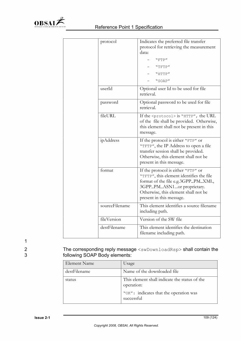
Reference Point 1 Specification
Issue 2-1 109 (124)
Copyright 2008, OBSAI, All Rights Reserved.
protocol
Indicates the preferred file transfer protocol for retrieving the measurement data:
- “FTP”
- “TFTP”
- “HTTP”
- “SOAP”
userId Optional user Id to be used for file retrieval.
password Optional password to be used for file retrieval.
fileURL If the <protocol> is “HTTP”, the URL of the file shall be provided. Otherwise, this element shall not be present in this message.
ipAddress If the protocol is either “FTP” or “TFTP”, the IP Address to open a file transfer session shall be provided. Otherwise, this element shall not be present in this message.
format If the protocol is either “FTP” or “TFTP”, this element identifies the file format of the file e.g.3GPP_PM_XML, 3GPP_PM_ASN1...or proprietary. Otherwise, this element shall not be present in this message.
sourceFilename This element identifies a source filename including path.
fileVersion Version of the SW file
destFilename This element identifies the destination filename including path.
1
2 3
The corresponding reply message <swDownloadRsp> shall contain the following SOAP Body elements: Element Name Usage
destFilename Name of the downloaded file
status This element shall indicate the status of the operation:
“OK”: indicates that the operation was successful

Reference Point 1 Specification
Issue 2-1 110 (124)
Copyright 2008, OBSAI, All Rights Reserved.
“fail”: indicates failure
failureReason If <status> element is present and is equal to “fail”, this field shall indicate the reason for the failure. Otherwise, it shall be omitted.
E.3.2 Inventory Request 1
2 3 4 5 6
7
The BTS Master Agent shall be able to perform an inventory of software and active processes on a module, using the swInventoryReq> command. The module shall respond with the version information and a list of active processes, using the <swInventoryRsp> message.
BTS MasterAgent
ModuleAgent
<swInventoryReq>
<swInventroyRsp>
8 9
10
11 12
13 14
Figure 48 Software Inventory Request-Response
The <swInventoryReq> message body has a no elements other than the message name tag.
The corresponding reply message <swInventoryRsp> shall contain the following SOAP Body elements: Element Name Sub-element
Name Usage
bldData
Element containing software build data
bldName Name of an individual module SW build
bldVersion Version of an individual module SW build
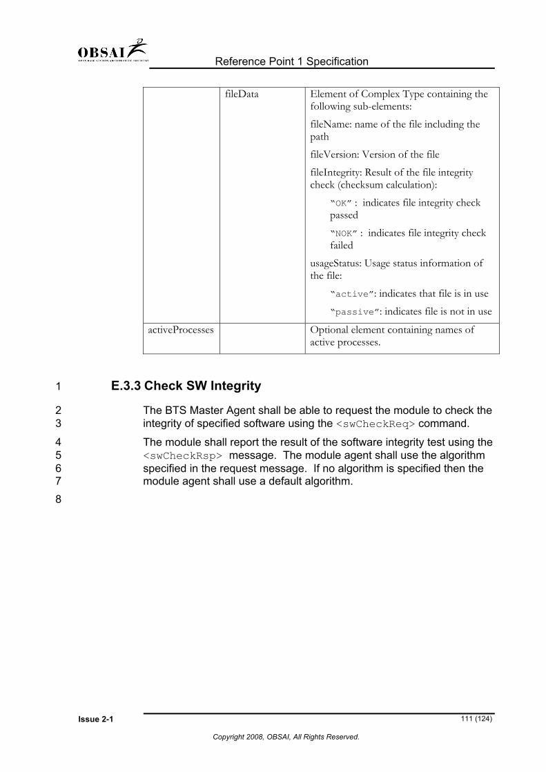
Reference Point 1 Specification
Issue 2-1 111 (124)
Copyright 2008, OBSAI, All Rights Reserved.
fileData Element of Complex Type containing the following sub-elements:
fileName: name of the file including the path
fileVersion: Version of the file
fileIntegrity: Result of the file integrity check (checksum calculation):
“OK” : indicates file integrity check passed
“NOK” : indicates file integrity check failed
usageStatus: Usage status information of the file:
“active”: indicates that file is in use
“passive”: indicates file is not in use
activeProcesses Optional element containing names of active processes.
E.3.3 Check SW Integrity 1
2 3
4 5 6 7 8
The BTS Master Agent shall be able to request the module to check the integrity of specified software using the <swCheckReq> command.
The module shall report the result of the software integrity test using the <swCheckRsp> message. The module agent shall use the algorithm specified in the request message. If no algorithm is specified then the module agent shall use a default algorithm.

Reference Point 1 Specification
Issue 2-1 112 (124)
Copyright 2008, OBSAI, All Rights Reserved.
BTS MasterAgent
ModuleAgent
<swCheckReq>
<swCheckRsp>
1 2 3
4 5
Figure 49 Software Check Request-Response
The <swCheckReq> message shall contain the following SOAP Body elements: Element Name Usage
fileName Name of an individual file in the active build on a module.
integrityAlgorithm Optional element indicating the integrity algorithm to be used.
6
7 8
The corresponding reply message <swCheckRsp> shall contain the following SOAP Body elements: Element Name Usage
fileName Name of an individual file in the active build on a module.
fileVersion Version of the file in the active build on a module.
fileIntegrity Indicates file status as follows: “OK” “FAIL” or,
checksum of the file
integrityAlgorithm Optional element indicating the integrity algorithm used
E.3.4 Save Software 9
10 11
The BTS Master Agent shall be able to request a module to save a downloaded file by using the <swSaveReq>.

Reference Point 1 Specification
Issue 2-1 113 (124)
Copyright 2008, OBSAI, All Rights Reserved.
The module shall save the file locally and communicate the result of the operation to the BTS Master Agent, using the <swSaveRsp> message.
1 2
BTS MasterAgent
ModuleAgent
<swSaveReq>
<swSaveRsp>
Save File
3 4 5
6 7
Figure 50 Save File Request-Response
The <swSaveReq> message shall contain the following SOAP Body elements: Element Name Usage
fileName Name of an individual file to be saved
checksum Checksum of the file to be saved provided by the master agent.
fileVersion Version of the file
fileType Indicates type of a file to be saved e.g., Boot, Runtime, Module Property File etc.
8
9 10
The corresponding reply message <swSaveRsp> shall contain the following SOAP Body elements: Element Name Usage
fileName Name of an individual file that was saved
fileVersion Version of the file
status Status of the file save operation:
“OK”: indicates successful file save
“fail”: indicates failed file save
failureReason If <status> element is present and is equal to “fail”, this field shall indicate the reason for the failure. Otherwise, it
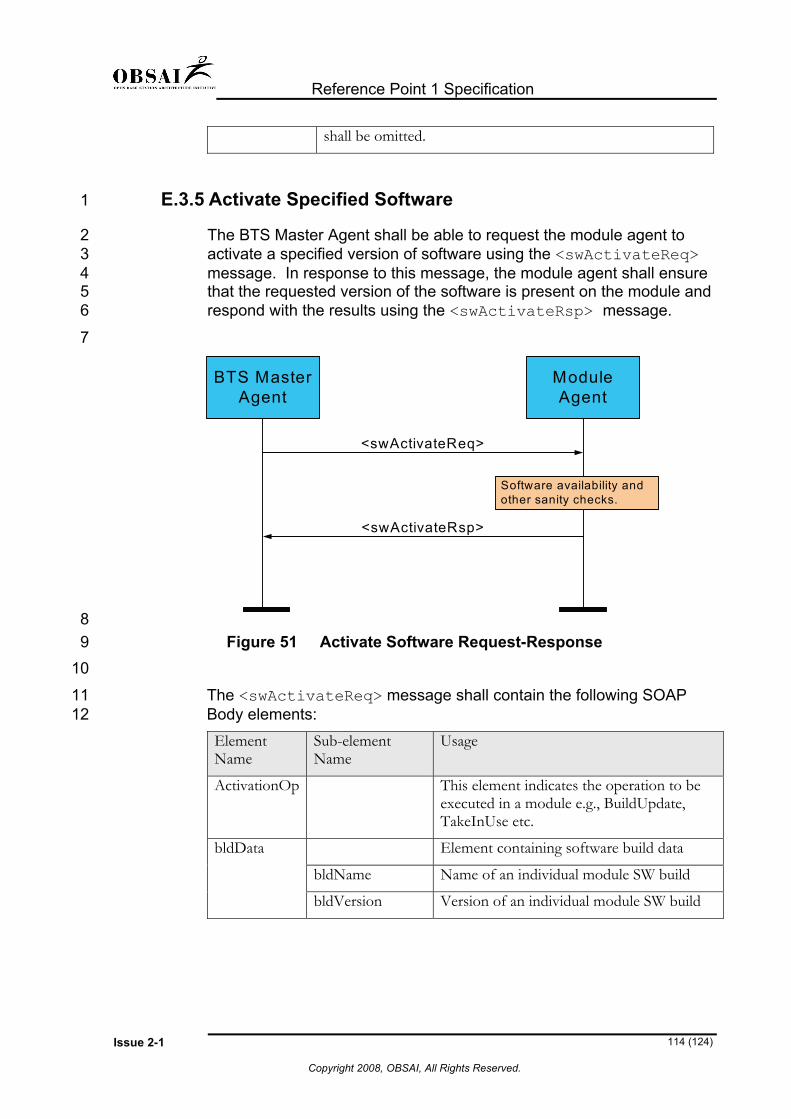
Reference Point 1 Specification
Issue 2-1 114 (124)
Copyright 2008, OBSAI, All Rights Reserved.
shall be omitted.
E.3.5 Activate Specified Software 1
2 3 4 5 6
7
The BTS Master Agent shall be able to request the module agent to activate a specified version of software using the <swActivateReq> message. In response to this message, the module agent shall ensure that the requested version of the software is present on the module and respond with the results using the <swActivateRsp> message.
BTS MasterAgent
ModuleAgent
<swActivateReq>
<swActivateRsp>
Software availability andother sanity checks.
8 9
10
11 12
Figure 51 Activate Software Request-Response
The <swActivateReq> message shall contain the following SOAP Body elements: Element Name
Sub-element Name
Usage
ActivationOp This element indicates the operation to be executed in a module e.g., BuildUpdate, TakeInUse etc.
bldData
Element containing software build data
bldName Name of an individual module SW build
bldVersion Version of an individual module SW build

Reference Point 1 Specification
Issue 2-1 115 (124)
Copyright 2008, OBSAI, All Rights Reserved.
fileData Element of Complex Type containing the following sub-elements:
fileName: name of the file including the path
fileVersion: Version of the file
1
2 3
The corresponding reply message <swActivateRsp> shall contain the following SOAP Body elements: Element Name Usage
status status of the activate SW operation:
“OK” indicates SW can be activated
“fail” indicates SW activation failure
failureReason If <status> element is present and is equal to “fail”, this field shall indicate the reason for the failure. Otherwise, it shall be omitted.
4
5
6
7 8
Glossary
Abbreviations For the purposes of the present document, the following abbreviations apply:
AAL ATM Adaptation Layer
AAL2 ATM Adaptation Layer type 2
AAL5 ATM Adaptation Layer type 5
AC Authentication Center
ADDS Application Data Delivery Service
AL Air Link
ALCAP Access Link Control Application Part
AMPS Advanced Mobile Phone System

Reference Point 1 Specification
Issue 2-1 116 (124)
Copyright 2008, OBSAI, All Rights Reserved.
ANID Access Network Identifiers
ANSI American National Standards Institute
ARFCN Absolute Radio Frequency Channel Number
ATM Asynchronous Transfer Mode
AUTHR Authentication Response
AUTHU Unique Challenge Authentication Response
BM-IWF Broadcast Multicast Interworking Function
BMC Broadcast/Multicast Control
BS Base Station
BSAP Base Station Application Part
BSC Base Station Controller
BSMAP Base Station Management Application Part
BSS Base Station Subsystem
BTS Base Transceiver System
CANID Current Access Network Identifiers
CBC Cell Broadcast Centre
CBS Cell Broadcast Service
CC Call Control
CDG CDMA Development Group
CDMA Code Division Multiple Access
CID Connection Identifier (used with reference to AAL2)
CIE Content Information Element
SwM Connection Management
CN Core Network
CNIP Calling Number Identification Presentation
CNIR Calling Number Identification Restriction
COUNT Call History Count
CPCH Common Packet Channel
CRNC Controlling Radio Network Controller
DCCH Dedicated Control Channel
DCH Dedicated Channel
DL Downlink
DLCI Data Link Connection Identifier
DLR Destination Local Reference
DPC Destination Point Code
DRNS Drift RNS
DRS Data Ready to Send
DS Direct Spread

Reference Point 1 Specification
Issue 2-1 117 (124)
Copyright 2008, OBSAI, All Rights Reserved.
DS0 Digital Signal Level 0
DS1 Digital Signal Level 1
DS-41 An operational mode in which the BS and MS operate with the direct spread (DS) radio layers of the UMTS system defined by 3GPP, and the upper layers defined in IS-2000 that conform to and interoperate with ANSI-41 based networks.
DTAP Direct Transfer Application Part
DTX Discontinuous Transmission
EDGE Enhanced Data rates for Global Evolution
EIA Electronics Industry Association
EIB Erasure Indicator Bit
ESN Electronic Serial Number
EVRC Enhanced Variable Rate Codec
FACH Forward Access Channel
FCH Fundamental Channel
FER Frame Error Rate
FFS For Further Study
FPC Forward Power Control
FQI Frame Quality Indicator
FSN Frame Sequence Number
GERAN GSM EDGE Radio Access Network
GR Gain Ratio
GRE Generic Routing Extension
GSM Global System for Mobile Communications
GTP GPRS Tunnelling Protocol
IEI Information Element Identifier
IETF Internet Engineering Task Force
IMSI International Mobile Subscriber Identity
IOS Interoperability Specification
IP Internet Protocol
IPv4 Internet Protocol, version 4
IPv6 Internet Protocol, version 6
ISDN Integrated Services Digital Network
ISLP Intersystem Link Protocol
ITU International Telecommunications Union
IWF Interworking Function
kb kilo bits
LA Location Area
LAC Location Area Code

Reference Point 1 Specification
Issue 2-1 118 (124)
Copyright 2008, OBSAI, All Rights Reserved.
LI Length Indicator
LSB Least Significant Bit
MAC Medium Access Control
MIN Mobile Identification Number
MIP Mobile IP
MM Mobility Management
MS Mobile Station
MSB Most Significant Bit
MSC Mobile Switching Center
MTP Message Transfer Part
MTP1 Message Transfer Part Layer 1
MTP2 Message Transfer Part Layer 2
MTP3 Message Transfer Part Layer 3
MWI Message Waiting Indication
N-AMPS Narrow band AMPS
NAS Non Access Stratum
NBAP Node B Application Part
NID Network Identification
NNSF NAS Node Selection Function
NSAP Network Service Access Point
OAM&P Operations, Administration, Maintenance, and Provisioning
OLT Outer Loop Threshold
OTAF Over The Air Function
OTAPA Over The Air Parameter Administration
OTASP Over The Air Service Provisioning
OTD Orthogonal Transmit Diversity
PACA Priority Access and Channel Assignment
PANID Previous Access Network Identifiers
PATE Packet Arrival Time Error
PCF Packet Control Function
PCH Paging Channel
PDE Position Determining Entity
PDSN Packet Data Serving Node
PIN Personal Identification Number
PLD Position Location Data
PLMN Public Land Mobile Network
PMC Packet Mode Channel
PN Pilot Number

Reference Point 1 Specification
Issue 2-1 119 (124)
Copyright 2008, OBSAI, All Rights Reserved.
PPP Point to Point Protocol
PSTN Public Switched Telephone Network
PZID Packet Zone Identifier
QCELP Q Code Excited Linear Prediction
QOF Quasi Orthogonal Function
QoS Quality of Service
QPCH Quick Paging Channel
RAB Radio Access Bearer
RACH Random Access Channel
RANAP Radio Access Network Application Part
RAND Random Variable
RANDC Random Confirmation
RANDSSD Random SSD
RANDU Random Variable - Unique Challenge
RC Radio Configuration, Radio Class
RF Radio Frequency
RFC Remote Feature Control
RLC Release Complete (SCCP)
RLP Radio Link Protocol
RLSD Release (SCCP)
RNC Radio Network Controller
RNL Radio Network Layer
RNS Radio Network Subsystem
RNSAP Radio Network Subsystem Application Part
RNTI Radio Network Temporary Identity
RPC Reverse Power Control
SAB Service Area Broadcast
SAS Standalone A-GPS SMLC
SAT Supervisory Audio Tone
SCCP Signaling Connection Control Part
SCH Supplemental Channel
SDB Short Data Burst
SDU Selection/Distribution Unit
SID System Identification
SLR Source Local Reference
SLTM Signaling Link Test Message
SME Signaling Message Encryption
SMS Short Message Service

Reference Point 1 Specification
Issue 2-1 120 (124)
Copyright 2008, OBSAI, All Rights Reserved.
SMS-MO SMS Mobile Originated
SMS-MT SMS Mobile Terminated
SNA Shared Network Area
SOAP Simple Object Access Protocol
SOCI Service Option Connection Identifier
SPI Security Parameter Index
SRNC Serving Radio Network Controller
SRNC-ID Source Radio Network Controller Identifier
SRNS Serving RNS
S-RNTI Source Radio Access Network Temporary Identifier
SSCF Service Specific Convergence Function
SSCOP Service Specific Connection Oriented Protocol
SSD Shared Secret Data
STP Signal Transfer Point
TCP Transmission Control Protocol
TEID Tunnel Endpoint Identifier
TFA Transfer-Allowed Signal
TFO Tandem Free Operation
TFP Transfer-Prohibited Signal
TFR Transfer-Restricted Signal
TIA Telecommunications Industry Association
TMSI Temporary Mobile Station Identity
TNL Transport Network Layer
TSB Telecommunications Systems Bulletin
TTI Transmission Time Interval
UDI Unrestricted Digital Information
UDP User Datagram Protocol
UE User Equipment
UL Uplink
UMTS Universal Mobile Telecommunication System
USIM UMTS Subscriber Identity Module
UTRAN Universal Terrestrial Radio Access Network
VLR Visitor Location Register
VP Voice Privacy

Reference Point 1 Specification
Issue 2-1 121 (124)
Copyright 2008, OBSAI, All Rights Reserved.
Definition of Terms 1
2 3 4 5 6 7 8 9
10 11 12 13 14 15 16 17 18 19 20 21 22 23 24 25 26 27 28 29 30 31 32 33 34 35 36 37 38 39 40
For the purposes of the present document, the following terms and definitions apply: Abis: designation of the interface between the Base Transceiver System (BTS) and the Base Station Controller (BSC) for IS-2000. TIA/EIA-828-A provides the specifications for this interface. ALCAP: generic name in 3GPP systems for the transport signaling protocols used to set-up and tear-down transport bearers Cell: Radio Network object that can be uniquely identified by a User Equipment from a (cell) identification that is broadcasted over a geographical area from one radio node. Iub: interface between the RNC and the Node B for 3GPP. Logical Model: Logical Model defines an abstract view of a network or network element by means of information objects representing network element, aggregations of network elements, the topological relationship between the elements, endpoints of connections (termination points), and transport entities (such as connections) that transport information between two or more termination points The information objects defined in the Logical Model are used, among others, by connection management functions. In this way, a physical implementation independent management is achieved. Node B: logical node in the OBSAI System responsible for radio transmission / reception in one or more cells to/from the UE. The logical node terminates the Iub interface towards the RNC. Packet: Used interchangeably with the term fragment in the context of UDPCP. Radio Resources: resources that constitute the radio interface in OBSAI, e.g. frequencies, scrambling codes, spreading factors, power for common and dedicated channels Radio Node B Application Part: Radio Network Signaling over the Iub Radio Network Controller: logical node in the RNS in charge of controlling the use and the integrity of the radio resources Controlling RNC: role an RNC can take with respect to a specific set of Node B's. There is only one Controlling RNC for any Node B. The Controlling RNC has the overall control of the logical resources of its node B's. Radio Network Subsystem: RNS can be either a full UTRAN or only a part of a UTRAN. An RNS offers the allocation and release of specific radio resources to establish means of connection in between an UE and the UTRAN. A Radio Network Subsystem contains one RNC and is

Reference Point 1 Specification
Issue 2-1 122 (124)
Copyright 2008, OBSAI, All Rights Reserved.
1 2 3 4 5 6 7 8 9
10 11 12 13 14 15 16 17 18 19 20 21 22 23 24 25 26 27 28 29 30 31
responsible for the resources and transmission/reception in a set of cells. Serving RNS: RNS can take this role with respect to a specific connection between a UE and UTRAN. There is one Serving RNS for each UE that has a connection to UTRAN. The Serving RNS is in charge of the radio connection between a UE and the UTRAN. The Serving RNS terminates the Iu for this UE. Radio Access Network Application Part: Radio Network Signaling over the Iu RRC Connection: point-to-point bi-directional connection between RRC peer entities on the UE and the UTRAN sides, respectively An UE has either zero or one RRC connection. User Equipment: Mobile Equipment with one or several UMTS Subscriber Identity Module(s). A device allowing a user access to network services via the Uu interface. Universal Terrestrial Radio Access Network: UTRAN is a conceptual term identifying that part of the network which consists of RNCs and Node Bs between Iu an Uu. UTRAN Access Point: conceptual point within the UTRAN performing radio transmission and reception A UTRAN access point is associated with one specific cell, i.e. there exists one UTRAN access point for each cell. It is the UTRAN-side end point of a radio link. Radio Link: "radio link" is a logical association between a single User Equipment and a single UTRAN access point Its physical realisation comprises one or more radio bearer transmissions. Radio Link Set: set of one or more Radio Links that has a common generation of Transmit Power Control (TPC) commands in the DL Uu: Radio interface between UTRAN and the User Equipment

References
Issue 2-1 123 (124)
Copyright 2008, OBSAI, All Rights Reserved.
References 1
2 3 4 5 6 7 8
[3GSwM] 3G TS 32.600, Version 5.0.1 3rd Generation Partnership Project; Technical Specification Group Services and System Aspects; Telecommunication Management; Configuration Management (SwM); Concept and high-level requirements (Release 5) Internet: http://www.3gpp.org/ 9
10 11 12 13 14
[3GOD] 3G TS 25.401, Version 6.1.0 3rd Generation Partnership Project; Technical Specification Group Radio Access Network; UTRAN Overall Description (Release 6) Internet: http://www.3gpp.org/ 15
16 17 18 19 20
[NBAP] 3G TS 25.433, Version 5.6.0 3rd Generation Partnership Project; Technical Specification Group Radio Access Network; UTRAN Iub interface NBAP Signaling (Release 5) Internet: http://www.3gpp.org/ 21
22 23 24
[ITU-T X.731] ITU-T Recommendation X.731: “Information Technology – Open Systems Interconnection – Systems Management: State management function Internet: http://www.3gpp.org/ 25
26 27 28
29 30 31
32 33
[OBSAI_Test] Open Base Station Architecture Initiative: RP1 Test Messages, Internet: www.obsai.org
[SOAP] Simple Object Access Protocol (SOAP) Version: 1.1 http://www.w3c.org/
[SOAPUS] SOAP Version 1.2 Usage Scenarios http://www.w3c.org/

References
Issue 2-1 124 (124)
Copyright 2008, OBSAI, All Rights Reserved.
1 2 3 4 5
[XMLSCHE] XML Schema Specification of World Wide Web Consortium XML Schema Part 1: Structures W3C Working Draft 24 September 1999 XML Schema Part 2: Datatypes W3C Working Draft 24 September 1999 http://www.w3c.org/ 6
7