Reference No: Assembly manual...
10
Stalprodukt S.A. Kind of document : Assembly manual Reference No: IM/MSD-36/12 Page: 1 Title : ASSEMBLY MANUAL OF ROAD SAFETY BARRIER StalPro Rail s according to EN 1317-5:2007+A1:2008 pkt 8 Pages: 3 Issue No: I Documentation of the producer According to EN 1317:5 standard point 5.2 Product description Equipment and employees The Contractor should produce evidence that he has the possibility to use special equipment to assemble and transport barriers, which is safe to use. The team performing road works should be under continuous supervision, executed by a properly qualified employee. The Contractor shall equip employees with means of individual protection. Vehicle marking and protection of the working place should be compliant with current legal regulations binding in the place where works are performed. Materials Materials should be compliant with requirements stated in Documentation of the Manufacturer. Individual barrier elements are packed in bundles with size depending on the weight of elements and the size of the commission. Small barrier elements are delivered in containers or cases. Each bundle or case shall have a tag including at least the following information: - name and address of the producer, - name of the product, together with the name and marking of the element, - date of production, - weight of the bundle, container or case, - number of items in one delivery Barrier elements should be stored in places and conditions, in which they shall not be exposed to mechanical defects or intensive corrosion. Stages of assembly works Assembly works include the following stages: 1) Preparatory works and measurements (indication of barrier road with verification of the course of underground installations, determination of posts location, indication of possible passage routes, crossings as well as final and initial barrier sections) 2) Placing posts of the protective barriers system – placing posts within the distance from the edge of the road stated in Project Documentation. During this stage of works it is essential to verify settlement, height and distance between posts. In case when placing posts of protective barriers system shall be executed by vibrating, due to cyclical blows of the pile- driver head on the head of the post, deformation and partial damage of the galvanized layer on the post is allowed. The scope of deformations and damages of the galvanized layer depends on the soil class and the degree of its concentration. This is a common phenomenon
-
Upload
phungxuyen -
Category
Documents
-
view
222 -
download
0
Transcript of Reference No: Assembly manual...

Stalprodukt S.A. Kind of document :
Assembly manual
Reference No:
IM/MSD-36/12
Page: 1 Title : ASSEMBLY MANUAL OF ROAD SAFETY BARRIER StalPro Rail s
according to EN 1317-5:2007+A1:2008 pkt 8 Pages: 3
Issue No:
I
Documentation of the producer
According to EN 1317:5 standard point 5.2 Product description
Equipment and employees
The Contractor should produce evidence that he has the possibility to use special equipment to
assemble and transport barriers, which is safe to use. The team performing road works should
be under continuous supervision, executed by a properly qualified employee. The Contractor
shall equip employees with means of individual protection. Vehicle marking and protection of
the working place should be compliant with current legal regulations binding in the place where
works are performed.
Materials
Materials should be compliant with requirements stated in Documentation of the Manufacturer.
Individual barrier elements are packed in bundles with size depending on the weight of
elements and the size of the commission. Small barrier elements are delivered in containers or
cases.
Each bundle or case shall have a tag including at least the following information:
- name and address of the producer,
- name of the product, together with the name and marking of the element,
- date of production,
- weight of the bundle, container or case,
- number of items in one delivery
Barrier elements should be stored in places and conditions, in which they shall not be exposed
to mechanical defects or intensive corrosion.
Stages of assembly works
Assembly works include the following stages:
1) Preparatory works and measurements (indication of barrier road with verification of the
course of underground installations, determination of posts location, indication of possible
passage routes, crossings as well as final and initial barrier sections)
2) Placing posts of the protective barriers system – placing posts within the distance from the
edge of the road stated in Project Documentation. During this stage of works it is essential to
verify settlement, height and distance between posts. In case when placing posts of
protective barriers system shall be executed by vibrating, due to cyclical blows of the pile-
driver head on the head of the post, deformation and partial damage of the galvanized layer
on the post is allowed. The scope of deformations and damages of the galvanized layer
depends on the soil class and the degree of its concentration. This is a common phenomenon

Stalprodukt S.A. Kind of document :
Assembly manual
Reference No:
IM/MSD-36/12
Page: 2 Title : ASSEMBLY MANUAL OF ROAD SAFETY BARRIER StalPro Rail s
according to EN 1317-5:2007+A1:2008 pkt 8 Pages: 3
Issue No:
I
and therefore it does not signify the quality of works. In such cases the damaged galvanized
layer is repaired with zinc paint. The deformed head of the post cannot be cut.
3) Assembly of protective barriers system – Assembly of protective barrier elements should be
made according to Documentation of the Producer and Project Documentation. When
assembling protective barriers system it is forbidden to make any holes or cuts violating the
galvanized layer of particular elements. Assembly of protective road barriers includes:
a) assembly of distancing elements within the protective barriers system with the use of
appropriate joining elements,
b) assembly of guides for distancing elements with the use of appropriate joining elements.
During this stage of works adjoining segments of guides need to be connected according
to the direction of vehicle movement, in a way, which in case of accident will enable the
vehicle to slide along protective barriers system without touching edges of the guides,
c) assembly of initial and final segments of protective barriers system
d) regulation of joining element’s tightening moment
e) checking the continuity of galvanized surface and repair of possible damages
f) fixing reflective elements on protective barriers system.
4) Quality control of the works should include:
a) verifying the compliance between the assembly of protective barriers system with Project
Documentation and Documentation of the Producer, with consideration of possible size
deviations,
b) test of galvanized layer thickness and its appearance
5) Site arrangement
Technical specification for road restraint system "StalPro Rail s" on ground:
Steel quality: S275JR in accordance with EN 10025-2
Hot-dip zinc coating:
-in accordance with EN ISO 1461
-continuous method according to EN 10346
Bolts:
Bolts in accordance with EN ISO 898-1
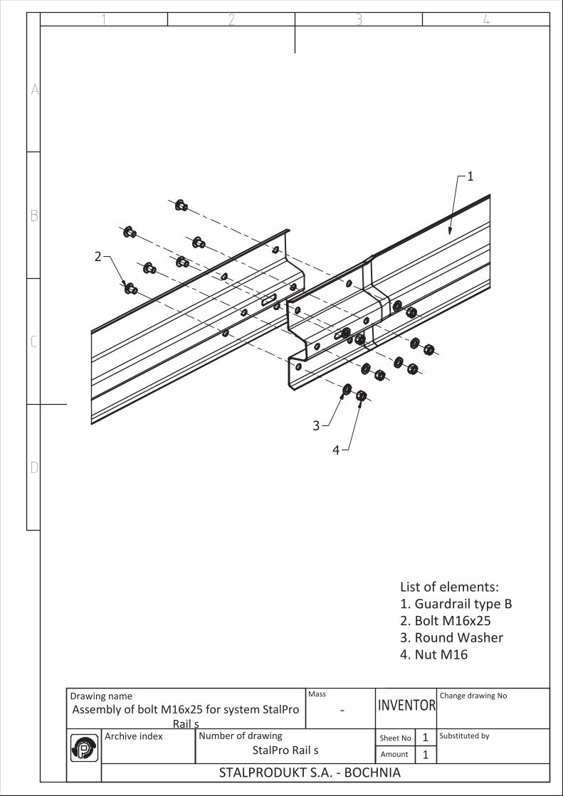
• M 16 x 25 according to drawing (appendix); property class 4.6
• M 16 x 40; property class 8.8
Nuts according to EN ISO 4032
Washers according to EN ISO 7091
Tightening torque of the bolts:
• M 16 - T = 70 ± 10 [Nm]

Stalprodukt S.A. Kind of document :
Assembly manual
Reference No:
IM/MSD-36/12
Page: 3 Title : ASSEMBLY MANUAL OF ROAD SAFETY BARRIER StalPro Rail s
according to EN 1317-5:2007+A1:2008 pkt 8 Pages: 3
Issue No:
I
Sequence of assembly in accordance with attached drawings:
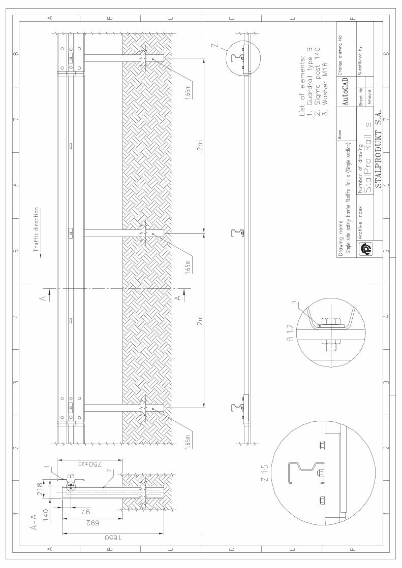
StalPro Rail s - Assembly drawing safety barrier StalPro Rail s
StalPro Rail s - Single side safety barrier StalPro Rail s (Single section)
StalPro Rail s - Terminal for system StalPro Rail s
StalPro Rail s - Single side safety barrier StalPro Rail s
StalPro Rail s - Assembly of bolt M16x40 for system StalPro Rail s
StalPro Rail s - Assembly of bolt M16x25 for system StalPro Rail s
Bolt M16xL
The tolerance for height of the top of the system is ±20mm.

�
�
�
�
�
�
��
�����������
�� ���� ��
���������� ����� ������ �������� ������ ����
������� ������ ���� �
�
�� ���� ������
�
�������������
�!"�#$�
�#�%��$�&'#��(�(���)$�*� �
����������� ���
+ ��
��������
%��������������,
�(�-� �� �����.��)
/(����� �.�����01
2(�3 �����+�4
�
�
�
������
�����


�
�
�
�
�
�
��
�����������
�� ���� ��
������������������������������������� ����
� ����
��� ��� ������ ���� �
�
!� ���� ����"�
#
� ����� �����
$"%&"'(�
�'�)��(�*+'��,�,�#�-(!."$�
" ��������� ���
� ��
������"�
)��������������/
�,�0 �� �����1��-
2,����� �1�������
3,�4 ��������
�,�-����������
5,��� �� ����
�,�" �����
�
�
�
�
�
�
�
�
�
�
�
�
�
�
�
��
�����������
�� ���� ��
������������������������������������� ����
� ����
��� ��� ������ ���� �
�
!� ���� ����"�
#
� ����� �����
$"%&"'(�
�'�)��(�*+'��,�,�#�-(!."$�
" ��������� ���
� ��
������"�
)��������������/
�,�0 �� �����1��-
�,�-����������
2,��� �3 ����
4,�" �����
�
�
�
�