Reference Manual - IDEC
472
Version 4.10 Reference Manual ™
Transcript of Reference Manual - IDEC
Version 4.10
Reference Manual
™
WLDR ReferenceBook Page 1 Thursday, April 5, 2001 3:36 PM

WLDR ReferenceBook Page 2 Thursday, April 5, 2001 3:36 PM
WindLDR™ Reference Manual
WLDR ReferenceBook Page 3 Thursday, April 5, 2001 3:36 PM
© 2001, IDEC Corporation. All rights reserved. Produced and printed in the
United States of America.
Important Information
While every effort has been made to ensure that the information contained
within this document is accurate, under no circumstances shall IDEC Corpora-
tion be held liable or responsible for indirect or consequential damages resulting
from the use of or the application of IDEC PLC components, individually or in
combination with other equipment.
In line with our policy of continuous improvement, we reserve the right to make
product changes without notice.
All persons using these components must be willing to accept responsibility for
choosing the correct component to suit their application and for choosing an
application appropriate for the component, individually or in combination with
other equipment.
All diagrams and examples in this manual are for illustrative purposes only. In no
way does the inclusion of these diagrams and examples in this manual constitute
a guarantee as to their suitability for any specific application. To test and approve
all programs prior to installation is the responsibility of the end user.
© 2001 IDEC Corporation

WindLDR™ Reference Manual
WLDR ReferenceBook Page 4 Thursday, April 5, 2001 3:36 PM
By using IDEC Corporation’s software product, you are consenting to be bound by the
IDEC Corporation software end user license agreement included as a part of this
package. If you do not agree to all of the terms of this agreement, you must erase all
installed IDEC Corporation software files from your system.
User Comments
IDEC Corporation is eager to receive comments about its products and docu-
mentation. Please phone, fax, mail, or e-mail any comments to:
IDEC Corporation
Marketing/Technical Documentation
1175 Elko Drive
Sunnyvale, CA 94089-2209
PH: 800-262-4332
FAX: 800-635-6246
www.idec.com
E-mail: [email protected]
© 2000 IDEC Corporation
Table of Contents
WLDR ReferenceBook Page I Thursday, April 5, 2001 3:36 PM
Chapter 1Introduction . . . . . . . . . . . . . . . . . . . . . . . . . . . . . . . . . . . . . . . . . . . . . . . . .1-1
WindLDR Version 4.0 Features 1-2WindLDR Package 1-3
Document Conventions 1-4On-Line Help 1-5CLIP and CUBIQ Shortcuts 1-6Technical Support 1-6
Installing WindLDR Software 1-7
Hardware/Software Recommendations 1-8
Chapter 2WindLDR Legends . . . . . . . . . . . . . . . . . . . . . . . . . . . . . . . . . . . . . . . . . . .2-1
Quick/Editing Keys 2-1
Icons 2-3Menu Commands Toolbar Icons 2-5Advanced Instruction Icons 2-7Basic Instruction Icons 2-8
Chapter 3File Menu . . . . . . . . . . . . . . . . . . . . . . . . . . . . . . . . . . . . . . . . . . . . . . . . . . .3-1
File➔ New 3-2
File➔ Open 3-2
© 2001 IDEC Corporation
II WindLDR™ Reference Manual
Table of C
WLDR ReferenceBook Page II Thursday, April 5, 2001 3:36 PM
File➔ Save 3-3
File➔ Save As 3-4
File➔ Listings➔ Ladder 3-5
File➔ Listings➔ Ladder Preview 3-5
File➔ Listings➔ Cover Page 3-6
File➔ Listings➔ Function Area Settings 3-6
File➔ Listings➔ Program Compare 3-6
File➔ Listings➔ Cross Reference 3-6
File➔ Listings➔ Tag Name 3-6
File➔ Print Setup 3-7
File➔ Exit WindLDR 3-7
Chapter 4Edit Menu . . . . . . . . . . . . . . . . . . . . . . . . . . . . . . . . . . . . . . . . . . . . . . . . . . 4-1
Edit➔ Undo 4-2
Edit➔ Cut / Copy / Paste 4-2
Edit➔ Select Rung / Select All 4-3
Edit➔ Find… 4-3
Edit➔ Insert / Append / Delete 4-4
Edit➔ Coil… 4-5
Edit➔ Edit Rung Comment… 4-6
Edit➔ Tag Name Editor… 4-7Function Keys within the Tag Name Editor 4-8Field Descriptions within the Tag Name Editor 4-9
ontents © 2001 IDEC Corporation
WindLDR™ Reference Manual III
WLDR ReferenceBook Page III Thursday, April 5, 2001 3:36 PM
Chapter 5View Menu . . . . . . . . . . . . . . . . . . . . . . . . . . . . . . . . . . . . . . . . . . . . . . . . . 5-1
View➔ Tool Bar 5-1
View➔ Status Bar 5-2
View➔ Tip Messages 5-2
Chapter 6Configure Menu . . . . . . . . . . . . . . . . . . . . . . . . . . . . . . . . . . . . . . . . . . . . . . 6-1
Configure➔ PLC Selection 6-2Micro-1 Configuration 6-3Micro3 Configuration and Micro3C Configuration 6-4FA Series Controller Configuration 6-5Open Net Controller Configuration 6-6MicroSmart Controller Configuration 6-7
Configure➔ Function Area Settings… 6-8Micro-1, FA1J, FA2J, FA3S (CP11/11T, CP12/13)
Function Area Settings 6-9Micro3, Micro3C, and ONC Function Area Settings 6-18ONC Function Area Settings 6-32MicroSmart Function Area Settings 6-34
Configure➔ Communication Settings… 6-35
Configure➔ Ladder preferences… 6-37
Chapter 7Compile Menu . . . . . . . . . . . . . . . . . . . . . . . . . . . . . . . . . . . . . . . . . . . . . . . 7-1
Compile➔ Convert Ladder 7-2
Compile➔ Show Errors 7-3
© 2001 IDEC Corporation Table of Contents
IV WindLDR™ Reference Manual
Table of C
WLDR ReferenceBook Page IV Thursday, April 5, 2001 3:36 PM
Chapter 8Online Menu . . . . . . . . . . . . . . . . . . . . . . . . . . . . . . . . . . . . . . . . . . . . . . . . 8-1
Online➔ Monitor 8-2
Online➔ Monitor➔ Online➔ Link Map 8-4
Online➔ Monitor➔ Online➔ Communication Error 8-5
Online➔ Monitor➔ Online➔ PLC status: 8-5Status Dialog (ONC, Micro3 and Micro3C) 8-5
Online➔ Monitor➔ Online➔ Direct monitor 8-14
Online➔ Monitor➔ Online➔ Point Write… 8-17
Online➔ Monitor➔ Online➔ Batch Monitor 8-20
Online➔ Upload program… 8-21Upload Dialog 8-23
Online➔ Download program… 8-24PLC Download Dialog 8-24
Chapter 9Editing the Ladder . . . . . . . . . . . . . . . . . . . . . . . . . . . . . . . . . . . . . . . . . . . . 9-1
Right Mouse➔ Edit rung comment… 9-2
Right Mouse➔ Help 9-3
Right Mouse➔ Line 9-3
Right Mouse➔ Basic Instructions 9-4Right Mouse➔ Basic Instructions➔ Normally Closed 9-10Right Mouse➔ Basic Instructions➔ Output (OUT) 9-12Right Mouse➔ Basic Instructions➔ Output Not (OUTN) 9-14Right Mouse➔ Basic Instructions➔ Set (SET) 9-16
ontents © 2001 IDEC Corporation
WindLDR™ Reference Manual V
WLDR ReferenceBook Page V Thursday, April 5, 2001 3:36 PM
Right Mouse➔ Basic Instructions➔ Reset (RST) 9-18Right Mouse➔ Basic Instructions➔ Single Output 9-20Right Mouse➔ Basic Instructions➔ Timere 9-22Right Mouse➔ Basic Instructions➔ Counter 9-26Right Mouse➔ Basic Instructions➔ Shift Register 9-33Right Mouse➔ Basic Instructions➔ Counter Comparison 9-39Right Mouse➔ Basic Instructions➔ Program Flow➔ Master
Control Set (MCS) and Master Control Reset (MCR) 9-42Right Mouse➔ Basic Instructions➔ Program Flow➔
Jump (JMP) and Jump End (JEND) 9-45Right Mouse➔ Basic Instructions➔ Program Flow➔ End (END) 9-49
Right Mouse➔ Advanced Instructions 9-50Structure of an Advanced Instruction 9-54Input Condition for Advanced Instructions 9-54Source and Destination Operands 9-55Using a Timer or Counter as a Source Operand 9-55Using a Timer or a Counter as Destination Operand 9-56Right Mouse➔ Advanced Instructions➔ Move➔ Move 9-57Right Mouse➔ Advanced Instructions➔ Move➔ Move Not 9-64Right Mouse➔ Advanced Instructions➔ Move➔
Indirect Move (IMOV) 9-69Right Mouse➔ Advanced Instructions➔ Move➔
Indirect Move Not (IMOVN) 9-74Right Mouse➔ Advanced Instructions➔ Comparison 9-78Right Mouse➔ Advanced Instructions➔ Binary Arithmetic 9-92Right Mouse➔ Advanced Instructions➔ Boolean Computation 9-103Right Mouse➔ Advanced Instructions➔ Bit Shift and Rotate 9-112Right Mouse➔ Advanced Instructions➔ Real-time
Clock/Calendar 9-122
© 2001 IDEC Corporation Table of Contents
VI WindLDR™ Reference Manual
Table of C
WLDR ReferenceBook Page VI Thursday, April 5, 2001 3:36 PM
Right Mouse➔ Advanced Instructions➔ Interface 9-137➔ Display (DISP) 9-137➔ Digital Read (DGRD) 9-142➔ Analog Read 0 (ANR0) 9-146Right Mouse➔ Advanced Instructions➔ Pulse
and A/D Conversion 9-149➔ Pulse Output (PULS) 9-150➔ Pulse Width Modulation (PWM) 9-156➔ Analog To Digital Conversion (A/D) 9-163Right Mouse➔ Advanced Instructions➔ High-Speed Counter 9-165➔ Single-stage Comparison (HSC0) 9-168➔ Multi-stage Comparison (HSC1) 9-175➔ Pulse Output Control (HSC2) 9-185➔ Gate Control (HSC3) 9-191Right Mouse➔ Advanced Instructions➔ Macro 9-198Right Mouse➔ Advanced Instructions➔ No Operation (NOP) 9-206Right Mouse➔ Insert 9-206Right Mouse➔ Append 9-207Right Mouse➔ Delete 9-207Right Mouse➔ Split Rung 9-208Right Mouse➔ Join Rung 9-208Right Mouse➔ Disable Rung 9-208
Chapter 10Transmit/Receive . . . . . . . . . . . . . . . . . . . . . . . . . . . . . . . . . . . . . . . . . . . . 10-1
Transmit (TXD) 10-8
Receive (RXD) 10-19
ontents © 2001 IDEC Corporation
WindLDR™ Reference Manual VII
WLDR ReferenceBook Page VII Thursday, April 5, 2001 3:36 PM
Appendix 1Allocation Numbers . . . . . . . . . . . . . . . . . . . . . . . . . . . . . . . . . . . . . . . . . .A1-1
Micro-1 PLC A1-1
Micro3 Allocation Numbers A1-5
Micro3C Allocation Numbers A1-12
Appendix 2Error Codes . . . . . . . . . . . . . . . . . . . . . . . . . . . . . . . . . . . . . . . . . . . . . . . .A2-1
General Error Codes A2-1First Digit Error Codes A2-2
Second Digit Error Codes A2-3
Third Digit Error Codes A2-4
Micro-1 Error Causes and Actions A2-4
Micro3 and Micro3C Error Codes A2-5
Master Error Lists for All PLCs A2-14
GlossaryGlossary . . . . . . . . . . . . . . . . . . . . . . . . . . . . . . . . . . . . . . . . . . . . . . . . . . . G-1
IndexIndex . . . . . . . . . . . . . . . . . . . . . . . . . . . . . . . . . . . . . . . . . . . . . . . . . . . Index I
© 2001 IDEC Corporation Table of Contents

VIII WindLDR™ Reference Manual
Table of C
WLDR ReferenceBook Page VIII Thursday, April 5, 2001 3:36 PM
ontents © 2001 IDEC Corporation
© 2001 IDEC Corporation
WLDR ReferenceBook Page 1 Thursday, April 5, 2001 3:36 PM
1. Introduction
Welcome to IDEC’s WindLDR™ configuration software package: where logic
and intuition converge! WindLDR is a true Windows application, with WYSI-
WYG (what you see is what you get) ladder editing.
The WindLDR™ Reference Manual provides an introduction to programming
IDEC’s full line of programmable logic controllers (PLCs) using IDEC’s Win-
dows-based ladder logic software. Use this manual as a reference for information
about your software package.
NOTE: Chapter 9, Chapter 10, Appendix 1, and Appendix 2 are geared toward the
Micro series of PLC’s. For similar instructions and details on the FA Series, the
Open Net Controller (ONC), and MicroSmart PLC’s, please refer to the corre-
sponding hardware manuals.
The WindLDR™ Tutorial presents a simple, quick-step approach to get you up-
and-running with a few basic applications. The Tutorial is a perfect introduction
to WindLDR or to programming your first PLC.
Using WindLDR can greatly increase productivity. Its easy-to-use features and
ability to quickly create ladder diagrams will save your company time and
money.
WindLDR provides programming configuration for IDEC’s full line of PLCs
and creates a bridge between older application software and hardware.
1. Introduction
1-2 WindLDR™ Reference Manual
1. Introdu
WLDR ReferenceBook Page 2 Thursday, April 5, 2001 3:36 PM
This chapter provides:
• A general description of the WindLDR software features • Documentation conventions used in the WindLDR manual set• Steps to a successful software installation
WindLDR Version 4.0 Features
WindLDR features cut and paste editing, enhanced on-line monitoring, and a
multi-level undo option which is limited only by available memory. With the
flexible Find String feature, WindLDR searches for a variety of text in a number
of ways, making it easier to handle large ladder files.
Use the menus of the context-sensitive right mouse button for convenient access
to the most commonly used commands. Toolbars, ladder file characteristics, and
other program features can be customized to the user’s preferences. The Tag Edi-
tor is a powerful way to access and edit all your coil data in one convenient place.
Printing your ladder diagrams is a snap with fully customizable formatting and
convenient Print Preview, Cross Reference, and Tag Name features to fine-tune
your documents. WindLDR can display mnemonics and/or machine code with
your ladder files. The monitoring feature enables you to debug and observe real-
time PLC functionality, right from your computer!
You no longer need to remember obscure codes and abbreviated
commands — with WindLDR, it’s just a simple drag and drop operation to
create any instruction.
ction © 2001 IDEC Corporation
WindLDR™ Reference Manual 1-3
WLDR ReferenceBook Page 3 Thursday, April 5, 2001 3:36 PM
WindLDR allows you to open multiple ladder files so you can compare and
reuse them instantly, even if they are written for different PLCs! The PLC Status
dialog provides valuable information at a glance, without remembering all those
complicated function codes.
The Point Write dialog allows you to change the preset values of operands with-
out having to stop monitoring and recompile your ladder file. The Direct Moni-
tor and Batch Monitor dialogs display the values of data in real-time. Coils can
be edited simply by double-clicking on them; no need to create new coils from
scratch. Along with IDEC’s quality PLCs, you get the service and software sup-
port you expect.
WindLDR is compatible with Windows 95, Windows 98, Windows 2000, and
Windows NT 4.0. So, transferring files across different platforms is quick and
easy.
WindLDR Package
When purchasing WindLDR software packages, the following items are
included:
• WindLDR configuration software on CD-ROM• WindLDR™ Reference Manual • WindLDR™ Tutorial • WindLDR software registration card• IDEC Corporation Software End User License Agreement
© 2001 IDEC Corporation 1. Introduction
1-4 WindLDR™ Reference Manual
1. Introdu
WLDR ReferenceBook Page 4 Thursday, April 5, 2001 3:36 PM
Document ConventionsThroughout this manual, you will find icons and key combinations specific to
the instructions. These particular documentation conventions are explained as
follows.
While all keyboards are set up uniquely, the ENTER, RETURN, or NEXT key
is always written as [ENTER] in this manual.
Additionally, referencing a common button, such as OK, Cancel, or Help, is
noted as the OK button.
In text, when an icon is available for use, it will be noted as: click either the -
or button.
Action items are denoted by the following arrow graphic.
Menu instructions are separated by an arrow (➔). For example, “Click Config-
ure ➔ PLC Selection” indicates for you to click Configure from the Menu
Commands toolbar and then to click PLC Selection from the drop down menu.
The majority of the WindLDR screens and dialog boxes are applicable to all PLC
types. However, some screens and dialog boxes differ depending on the PLC
type. Unless there is a difference among PLC types, all screen and dialog box
examples in this tutorial will reflect the Open Net Controller (ONC) PLC.
Alongside this symbol, the corresponding action items always print.
Follow these directions to easily complete all procedures.
Action items requiring a specific entry will be printed, for example,
as enter: 1234 at the prompt.
ction © 2001 IDEC Corporation
WindLDR™ Reference Manual 1-5
the f an such our nt.
WLDR ReferenceBook Page 5 Thursday, April 5, 2001 3:36 PM
Within this reference manual, Chapters 3 through 8 describe the options avail-
able from the Menu Commands toolbar. Chapter 9 includes details about all the
basic and advanced instructions which allow you to program and edit your lad-
der. Finally, Chapters 10 and 11 explain the advanced instruction, mainly appli-
cable to the Micro PLC series. For details on other PLC’s, like the FA series, the
ONC, and the MicroSmart, please refer to the appropriate user’s manual.
Basic instructions are applicable to all PLC types. However, advanced instruc-
tions are only applicable to certain PLC’s.
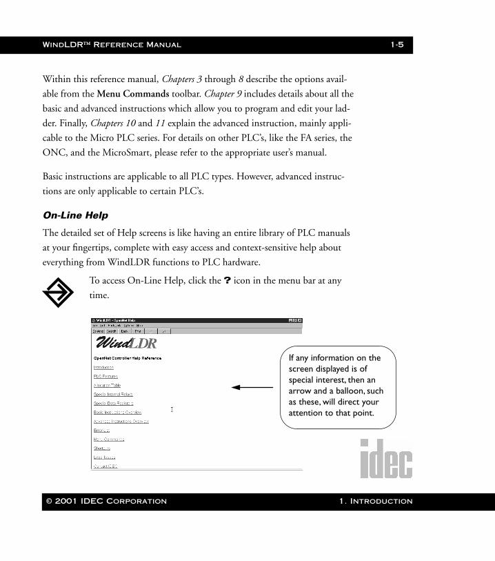
On-Line Help
The detailed set of Help screens is like having an entire library of PLC manuals
at your fingertips, complete with easy access and context-sensitive help about
everything from WindLDR functions to PLC hardware.
To access On-Line Help, click the ? icon in the menu bar at any
time.
If any information onscreen displayed is ospecial interest, thenarrow and a balloon,as these, will direct yattention to that poi
© 2001 IDEC Corporation 1. Introduction
1-6 WindLDR™ Reference Manual
1. Introdu
WLDR ReferenceBook Page 6 Thursday, April 5, 2001 3:36 PM
CLIP and CUBIQ Shortcuts
Many shortcut elements from CLIP and CUBIQ are present in WindLDR. So,
if you are familiar with these shortcut keys, they are also available with this pro-
gram. For example:
• Typing characters while in the editing mode will automatically bring up the Coil Selection Dialog screen with the first letter of the command abbrevia-tion highlighted.
• You can easily draw ladder lines in WindLDR by holding the [SHIFT] key and using the arrow keys to draw.
• Ladder lines can just as easily be erased by holding down the [CONTROL] key and using the arrow keys to erase.
WARNING: Unlike CLIP and CUBIQ, WindLDR uses rungs (blocks of logic) in
building ladder programs. Users must exercise caution and keep the size of the rung
to a minimum. Large and tedious rungs produce unpredicted errors and prob-
lems in WindLDR.
Technical Support
Registered users of IDEC’s WindLDR software are entitled to telephone support.
To qualify, complete the enclosed registration card and return it to IDEC. For
assistance, call 1-800-262-IDEC (4332) extension 7526 to contact the PLC
Technical Engineering Group.
To contact us through E-mail, write to [email protected] via the Internet.
ction © 2001 IDEC Corporation
WindLDR™ Reference Manual 1-7
WLDR ReferenceBook Page 7 Thursday, April 5, 2001 3:36 PM
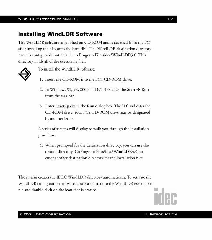
Installing WindLDR Software The WindLDR software is supplied on CD-ROM and is accessed from the PC
after installing the files onto the hard disk. The WindLDR destination directory
name is configurable but defaults to Program Files\idec\WindLDR3.0. This
directory holds all of the executable files.
The system creates the IDEC WindLDR directory automatically. To activate the
WindLDR configuration software, create a shortcut to the WindLDR executable
file and double-click on the icon that is created.
To install the WindLDR software:
1. Insert the CD-ROM into the PC’s CD-ROM drive.
2. In Windows 95, 98, 2000 and NT 4.0, click the Start ➔ Run
from the task bar.
3. Enter D:setup.exe in the Run dialog box. The “D” indicates the
CD-ROM drive. Your PC’s CD-ROM drive may be designated
by another letter.
A series of screens will display to walk you through the installation
procedures.
4. When prompted for the destination directory, you can use the
default directory, C:\Program Files\idec\WindLDR4.0, or
enter another destination directory for the installation files.
© 2001 IDEC Corporation 1. Introduction
1-8 WindLDR™ Reference Manual
1. Introdu
WLDR ReferenceBook Page 8 Thursday, April 5, 2001 3:36 PM
Hardware/Software Recommendations
WindLDR will run on a Pentium based PC running Microsoft® Windows® 95
or 98 with at least 24MB of available RAM and Windows® 2000 or NT4.0 with
32MB of available RAM.
ction © 2001 IDEC Corporation
© 2001 IDEC Corporation
WLDR ReferenceBook Page 1 Thursday, April 5, 2001 3:36 PM
2. WindLDR Legends
Throughout the WindLDR software, a number of quick keys, icons, and alloca-
tions exist. This chapter will demystify their naming conventions and their corre-
sponding functionality.
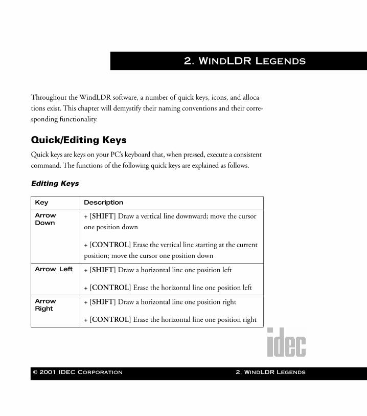
Quick/Editing KeysQuick keys are keys on your PC’s keyboard that, when pressed, execute a consistent
command. The functions of the following quick keys are explained as follows.
Editing Keys
Key Description
Arrow Down
+ [SHIFT] Draw a vertical line downward; move the cursor
one position down
+ [CONTROL] Erase the vertical line starting at the current
position; move the cursor one position down
Arrow Left + [SHIFT] Draw a horizontal line one position left
+ [CONTROL] Erase the horizontal line one position left
Arrow Right
+ [SHIFT] Draw a horizontal line one position right
+ [CONTROL] Erase the horizontal line one position right
2. WindLDR Legends
2-2 WindLDR™ Reference Manual
2. WindLDR
WLDR ReferenceBook Page 2 Thursday, April 5, 2001 3:36 PM
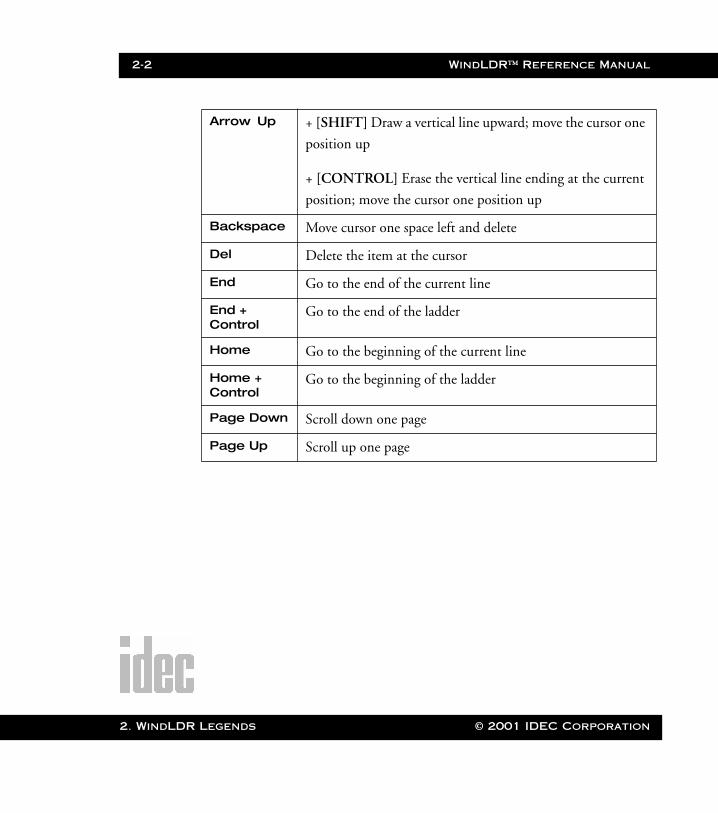
Arrow Up + [SHIFT] Draw a vertical line upward; move the cursor one
position up
+ [CONTROL] Erase the vertical line ending at the current
position; move the cursor one position up
Backspace Move cursor one space left and delete
Del Delete the item at the cursor
End Go to the end of the current line
End + Control
Go to the end of the ladder
Home Go to the beginning of the current line
Home +Control
Go to the beginning of the ladder
Page Down Scroll down one page
Page Up Scroll up one page
Legends © 2001 IDEC Corporation
WindLDR™ Reference Manual 2-3
WLDR ReferenceBook Page 3 Thursday, April 5, 2001 3:36 PM
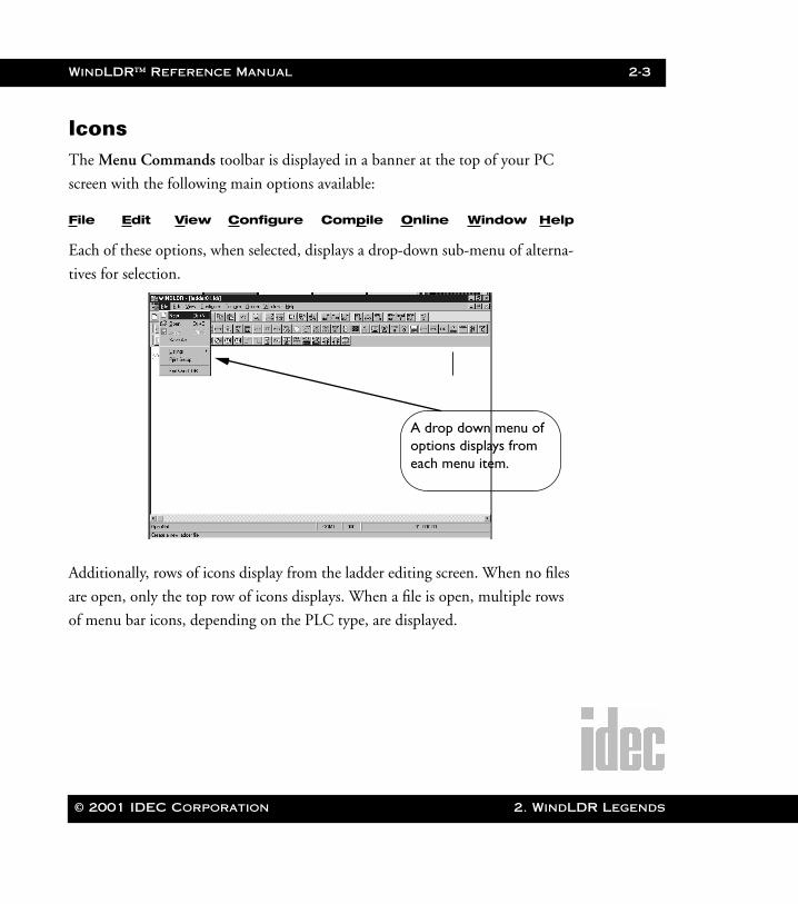
IconsThe Menu Commands toolbar is displayed in a banner at the top of your PC
screen with the following main options available:
File Edit View Configure Compile Online Window Help
Each of these options, when selected, displays a drop-down sub-menu of alterna-
tives for selection.
Additionally, rows of icons display from the ladder editing screen. When no files
are open, only the top row of icons displays. When a file is open, multiple rows
of menu bar icons, depending on the PLC type, are displayed.
A drop down menu of options displays from each menu item.
© 2001 IDEC Corporation 2. WindLDR Legends
2-4 WindLDR™ Reference Manual
2. WindLDR
WLDR ReferenceBook Page 4 Thursday, April 5, 2001 3:36 PM
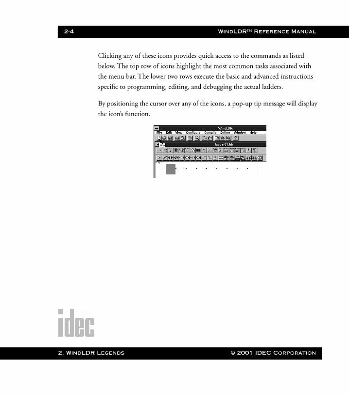
Clicking any of these icons provides quick access to the commands as listed
below. The top row of icons highlight the most common tasks associated with
the menu bar. The lower two rows execute the basic and advanced instructions
specific to programming, editing, and debugging the actual ladders.
By positioning the cursor over any of the icons, a pop-up tip message will display
the icon’s function.
Legends © 2001 IDEC Corporation
WindLDR™ Reference Manual 2-5
WLDR ReferenceBook Page 5 Thursday, April 5, 2001 3:36 PM
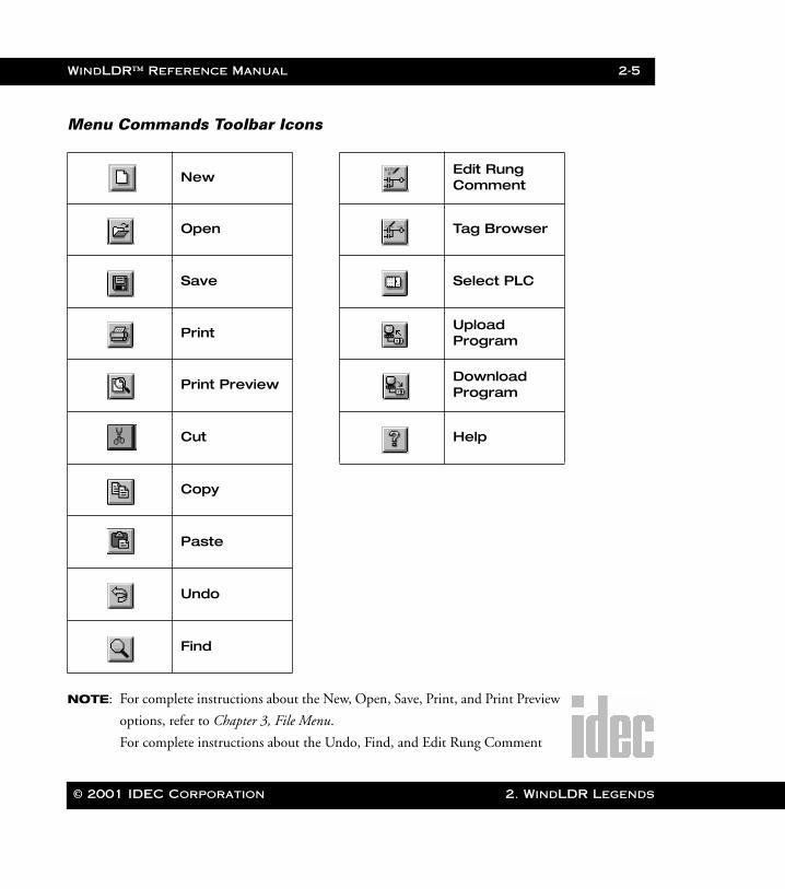
Menu Commands Toolbar Icons
NOTE: For complete instructions about the New, Open, Save, Print, and Print Preview
options, refer to Chapter 3, File Menu.
For complete instructions about the Undo, Find, and Edit Rung Comment
NewEdit Rung Comment
Open Tag Browser
Save Select PLC
PrintUpload Program
Print PreviewDownload Program
Cut Help
Copy
Paste
Undo
Find
© 2001 IDEC Corporation 2. WindLDR Legends
2-6 WindLDR™ Reference Manual
2. WindLDR
WLDR ReferenceBook Page 6 Thursday, April 5, 2001 3:36 PM
options, refer to Chapter 4, Edit Menu.
For complete instructions about the Select PLC option, refer to Chapter 6. Con-
figure Menu.
For complete instructions about the Upload Program and Download Program
options, refer to Chapter 8, Online Menu.
For complete instructions about the Help option, refer to page 1-5 and to
Chapter 9, Editing the Ladder.
Legends © 2001 IDEC Corporation

WindLDR™ Reference Manual 2-7
WLDR ReferenceBook Page 7 Thursday, April 5, 2001 3:36 PM
Advanced Instruction Icons
Move Pulse
Indirect MoveAnalog to Digital
CompareHSC0: Single Stage Comparison
Binary Arithmetic
HSC1: Multi-Stage Comparison
BooleanHSC2: Pulse Output Control
Bit Shift/Rotate
HSC3: Gate Control
Clock/Calendar
Transmit/Receive(available w/
Micro3C only)
Display Macro
Digital Read No Operation
Analog Read
© 2001 IDEC Corporation 2. WindLDR Legends
2-8 WindLDR™ Reference Manual
2. WindLDR
WLDR ReferenceBook Page 8 Thursday, April 5, 2001 3:36 PM
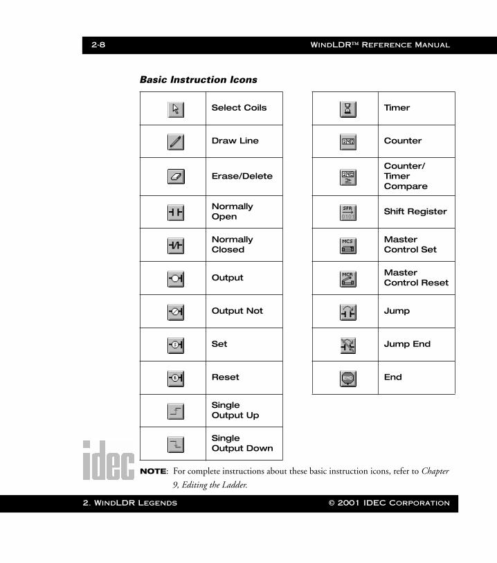
Basic Instruction Icons
NOTE: For complete instructions about these basic instruction icons, refer to Chapter
9, Editing the Ladder.
Select Coils Timer
Draw Line Counter
Erase/DeleteCounter/TimerCompare
Normally Open
Shift Register
Normally Closed
Master Control Set
Output Master Control Reset
Output Not Jump
Set Jump End
Reset End
Single Output Up
Single Output Down
Legends © 2001 IDEC Corporation
© 2001 IDEC Corporation
WLDR ReferenceBook Page 1 Thursday, April 5, 2001 3:36 PM
3. File Menu
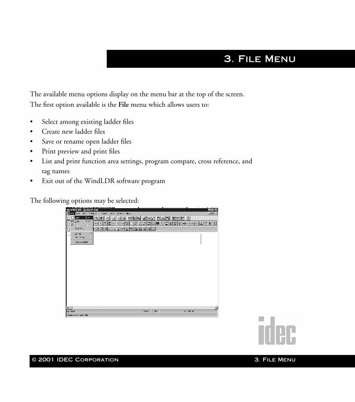
The available menu options display on the menu bar at the top of the screen.
The first option available is the File menu which allows users to:
• Select among existing ladder files • Create new ladder files• Save or rename open ladder files• Print preview and print files• List and print function area settings, program compare, cross reference, and
tag names• Exit out of the WindLDR software program
The following options may be selected:
3. File Menu
3-2 WindLDR™ Reference Manual
3. File Men
WLDR ReferenceBook Page 2 Thursday, April 5, 2001 3:36 PM
File➔NewSelecting the New option from the File menu opens a new, empty WindLDR
ladder file. This newly created file is numbered to reflect its order of creation.
The new file format is determined by the default or current PLC settings. A dia-
log box will not display with this option. To name the ladder file, select the Save
or Save As option from the File menu.
You may also click the toolbar button:
NOTE: You may open up to 11 ladder files at once.
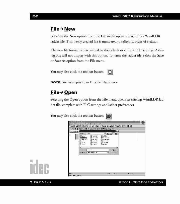
File➔OpenSelecting the Open option from the File menu opens an existing WindLDR lad-
der file, complete with PLC settings and ladder preferences.
You may also click the toolbar button:
u © 2001 IDEC Corporation
WindLDR™ Reference Manual 3-3
WLDR ReferenceBook Page 3 Thursday, April 5, 2001 3:36 PM
File Name:
Within the Open dialog box, select a file name by clicking to highlight it, or
enter the desired ladder file into the File Name: field.
List Files of Type:
All ladder files should have the file extension .ldr.
Directories:
Unless otherwise specified, the default directory of all ladder files is C:\windldr.
If you wish to access another directory, use the scroll bars and your mouse button
to highlight the appropriate directory.
Drives:
Use the arrow icon and your mouse button to select among available drives
within this field. In general, the “c” drive is your hard drive and the “a” drive is
your floppy drive.
NOTE: You may open up to 11 ladder files at once.
File➔SaveSelecting the Save option from the File menu saves the active WindLDR ladder
file, complete with PLC settings and ladder preferences.
You may also click the toolbar button:
Once the appropriate file name, drive, and directory have been
selected, click the OK button.
To back out of this option without opening a file, click the Cancel
button.
© 2001 IDEC Corporation 3. File Menu
3-4 WindLDR™ Reference Manual
3. File Men
WLDR ReferenceBook Page 4 Thursday, April 5, 2001 3:36 PM
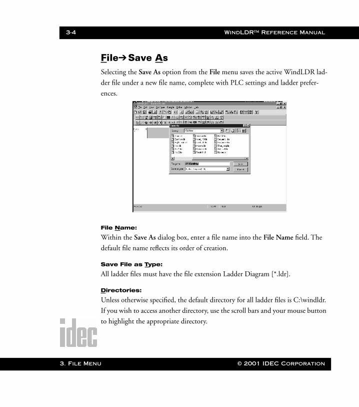
File➔Save AsSelecting the Save As option from the File menu saves the active WindLDR lad-
der file under a new file name, complete with PLC settings and ladder prefer-
ences.
File Name:
Within the Save As dialog box, enter a file name into the File Name field. The
default file name reflects its order of creation.
Save File as Type:
All ladder files must have the file extension Ladder Diagram [*.ldr].
Directories:
Unless otherwise specified, the default directory for all ladder files is C:\windldr.
If you wish to access another directory, use the scroll bars and your mouse button
to highlight the appropriate directory.
u © 2001 IDEC Corporation
WindLDR™ Reference Manual 3-5
WLDR ReferenceBook Page 5 Thursday, April 5, 2001 3:36 PM
Drives:
Use the arrow icon and your mouse button to select among available drives
within this field. In general, the “c” drive is your hard drive and the “a” drive is
your floppy drive.
File➔Listings➔LadderSelecting the Listings option from the File menu allows the user to view/print
the following features: Ladder, Ladder Preview, Function Area Settings, Pro-
gram Compare, Cross Reference, and Tag Name.
To simply print the ladder program, choose Ladder, then click OK.
You may also click the toolbar button:
File➔Listings➔Ladder PreviewSelecting the Ladder Preview option from the File ➔ Listings menu displays the
pages of the ladder file as they would appear when printed. You may view one or
two pages at a time.
You may also click the toolbar button:
Once the appropriate file name, drive, and directory have been
entered, click the OK button.
To back out of this option without saving or renaming the file, click
the Cancel button.
© 2001 IDEC Corporation 3. File Menu
3-6 WindLDR™ Reference Manual
3. File Men
WLDR ReferenceBook Page 6 Thursday, April 5, 2001 3:36 PM
Depending upon the printer device you have installed, the Print Preview dialog
box will reflect the printer’s configuration. Follow the instructions enclosed with
your printer for specific printing instructions.
File➔Listings➔Cover PageSelecting the Cover Page option from the File menu will allow you to create a
cover page for the project and print it separately from the ladder screen.
File➔Listings➔Function Area SettingsSelecting the Function Area Settings from the File menu will allow you to view
certain PLC settings with an option to print them.
File➔Listings➔Program CompareSelecting the Program Compare option will allow you to compare two code files:
the uploaded file (from a PLC) and the working file for match or mis-match.
File➔Listings➔Cross ReferenceSelecting the Cross Reference option from the File ➔ Listings menu will display
the reference of all the operands of the ladder file in a Microsoft Notepad format,
with the option to print it.
File➔Listings➔Tag NameSelecting the Tag Name option from the File ➔ Listings menu will display all
the tag names in the ladder file in a Microsoft Notepad file, with an option to
print it.
u © 2001 IDEC Corporation

WindLDR™ Reference Manual 3-7
WLDR ReferenceBook Page 7 Thursday, April 5, 2001 3:36 PM
File➔Print SetupSelecting the Print Setup option from the File menu displays the options to
select a printer, the page orientation, and the paper size. Additionally, you may
change specific printer settings and the default printing device.
Depending upon the printer device you have installed, the Print Setup dialog
box will reflect the printer’s configuration. Follow the instructions enclosed with
your printer for specific printing instructions.
File➔Exit WindLDRSelecting the Exit WindLDR option from the File menu ends the WindLDR
program. You are given the choice to save any modified ladder files.
© 2001 IDEC Corporation 3. File Menu

3-8 WindLDR™ Reference Manual
3. File Men
WLDR ReferenceBook Page 8 Thursday, April 5, 2001 3:36 PM
u © 2001 IDEC Corporation
© 2001 IDEC Corporation
WLDR ReferenceBook Page 1 Thursday, April 5, 2001 3:36 PM
4. Edit Menu
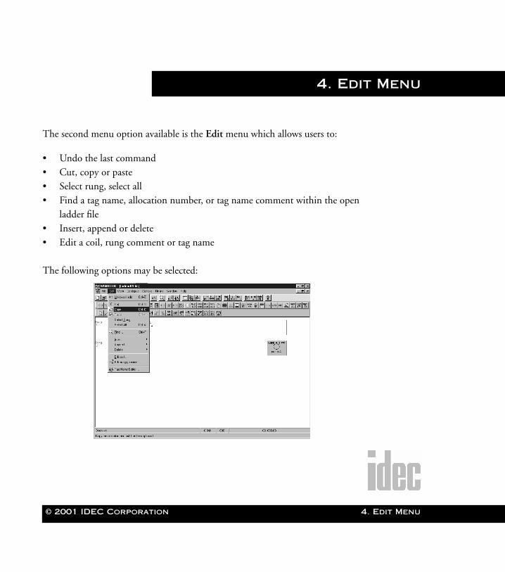
The second menu option available is the Edit menu which allows users to:
• Undo the last command • Cut, copy or paste• Select rung, select all• Find a tag name, allocation number, or tag name comment within the open
ladder file• Insert, append or delete• Edit a coil, rung comment or tag name
The following options may be selected:
4. Edit Menu
4-2 WindLDR™ Reference Manual
4. Edit Men
WLDR ReferenceBook Page 2 Thursday, April 5, 2001 3:36 PM
Edit➔UndoSelecting the Undo option from the Edit menu reverses the last editing action.
Additionally, WindLDR allows multiple undos. Each time Undo is selected, the
previous chronological action is reversed. Nevertheless, once a ladder file is saved,
the Undo option is no longer available.
You may also click the toolbar button:
Additionally, when the Undo option is selected from the File menu, the nature of
the command which will be reversed displays.
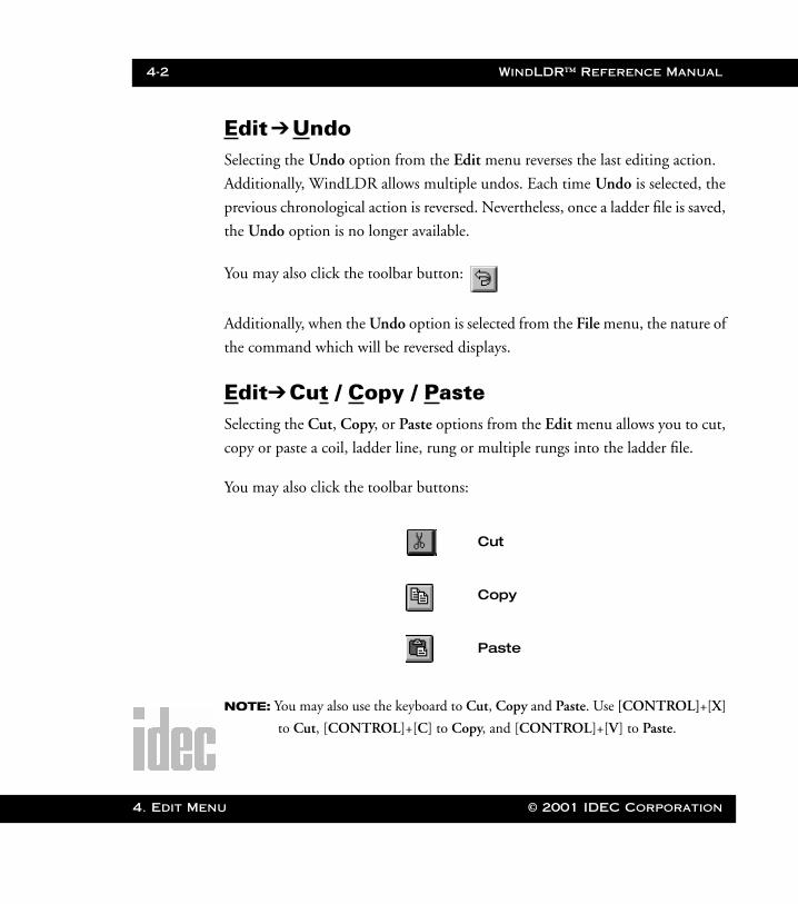
Edit➔Cut / Copy / PasteSelecting the Cut, Copy, or Paste options from the Edit menu allows you to cut,
copy or paste a coil, ladder line, rung or multiple rungs into the ladder file.
You may also click the toolbar buttons:
NOTE: You may also use the keyboard to Cut, Copy and Paste. Use [CONTROL]+[X]
to Cut, [CONTROL]+[C] to Copy, and [CONTROL]+[V] to Paste.
Cut
Copy
Paste
u © 2001 IDEC Corporation
WindLDR™ Reference Manual 4-3
WLDR ReferenceBook Page 3 Thursday, April 5, 2001 3:36 PM
Edit➔Select Rung / Select AllThis option allows you to select a particular rung or all the rungs of a ladder file
in order to Cut, Copy or Paste.
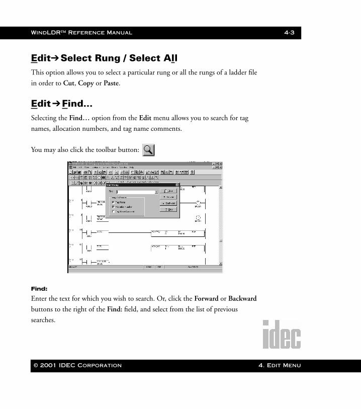
Edit➔Find…Selecting the Find… option from the Edit menu allows you to search for tag
names, allocation numbers, and tag name comments.
You may also click the toolbar button:
Find:
Enter the text for which you wish to search. Or, click the Forward or Backward
buttons to the right of the Find: field, and select from the list of previous
searches.
© 2001 IDEC Corporation 4. Edit Menu
4-4 WindLDR™ Reference Manual
4. Edit Men
WLDR ReferenceBook Page 4 Thursday, April 5, 2001 3:36 PM
Things to Search:
Select one, two, or all of the search options (Tag Name, Allocation Number, and
Tag Name Comment).
Examples of tag names are I1, Q4, T3, D30 and so forth. For a complete listing
of available allocation numbers, refer to Appendix 1: Allocation Number Table.
Tag name comments are user-supplied comment strings for coils.
Edit➔ Insert / Append / DeleteSelecting Insert allows you to insert a ladder line, column, or rung at any point
in the program and in any location. Selecting the Append option allows you to
append a ladder line, column or rung at any point in the program and in any
location. Selecting Delete allows you to delete a coil, ladder line, column or rung
at any time.
NOTE: You may also delete a coil, ladder line or rung by selecting it and using the
[DELETE] button on your keyboard.
Once the appropriate text string and search option(s) have been
selected, click either the Forward or Backward button. The For-
ward button will find the previous occurrence of the text string. The
Backward button will find the next occurrence of the text string.
To back out of this option, click the Cancel button. To access on-
line help, press the Help button.
u © 2001 IDEC Corporation
WindLDR™ Reference Manual 4-5
WLDR ReferenceBook Page 5 Thursday, April 5, 2001 3:36 PM
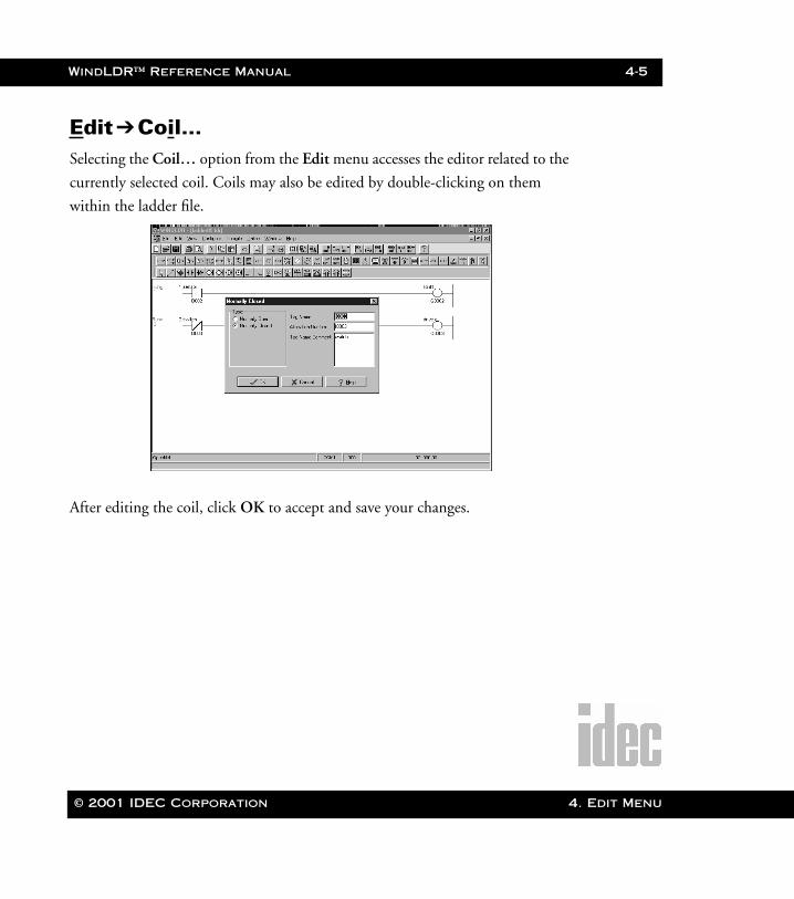
Edit➔Coil…Selecting the Coil… option from the Edit menu accesses the editor related to the
currently selected coil. Coils may also be edited by double-clicking on them
within the ladder file.
After editing the coil, click OK to accept and save your changes.
© 2001 IDEC Corporation 4. Edit Menu
4-6 WindLDR™ Reference Manual
4. Edit Men
WLDR ReferenceBook Page 6 Thursday, April 5, 2001 3:36 PM
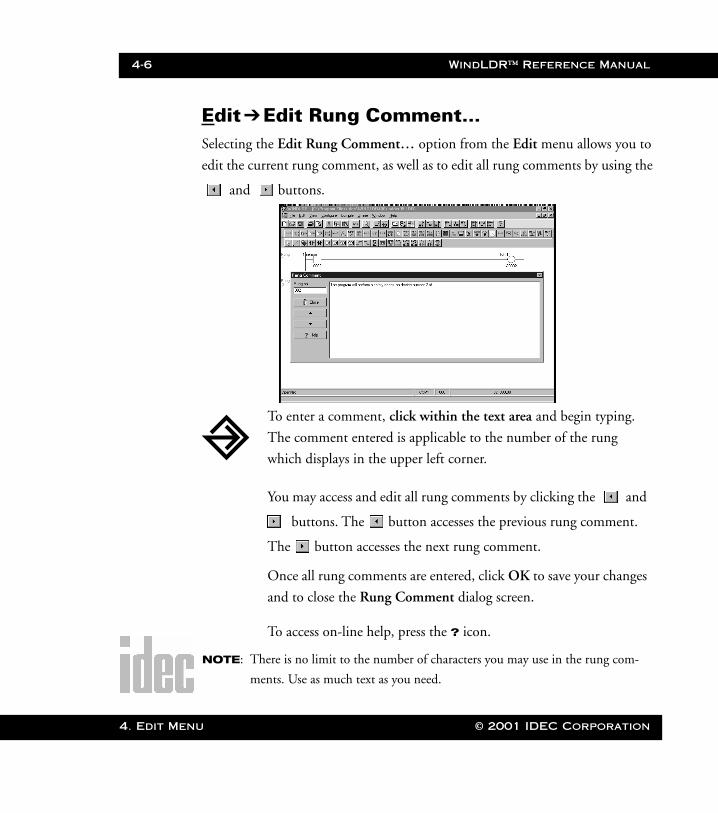
Edit➔Edit Rung Comment…Selecting the Edit Rung Comment… option from the Edit menu allows you to
edit the current rung comment, as well as to edit all rung comments by using the
and buttons.
NOTE: There is no limit to the number of characters you may use in the rung com-
ments. Use as much text as you need.
To enter a comment, click within the text area and begin typing.
The comment entered is applicable to the number of the rung
which displays in the upper left corner.
You may access and edit all rung comments by clicking the and
buttons. The button accesses the previous rung comment.
The button accesses the next rung comment.
Once all rung comments are entered, click OK to save your changes
and to close the Rung Comment dialog screen.
To access on-line help, press the ? icon.
u © 2001 IDEC Corporation

WindLDR™ Reference Manual 4-7
WLDR ReferenceBook Page 7 Thursday, April 5, 2001 3:36 PM
Edit➔Tag Name Editor…Selecting the Tag Name Editor… option from the Edit menu provides a conve-
nient way to find and edit coils in large ladder files. It is possible to scroll through
coils based on operand type, tag name, allocation number, or comments.
To select a Tag Name, click on the entry to highlight it. Once one is
selected, you may edit its tag name, allocation number, and tag
name comment within the fields to the right. Use the top field to
edit the tag name, the middle field to edit the allocation number,
and the bottom field to edit the tag name comment.
Clicking on the various headings will rearrange the order of the tag
names accordingly. To rearrange the tag names in ascending order,
click on the Tag Name heading. To rearrange the allocation num-
bers in ascending order, click on the Alloc No heading. To rearrange
the tag name comments in ascending order, click on the Comment
heading.
© 2001 IDEC Corporation 4. Edit Menu

4-8 WindLDR™ Reference Manual
4. Edit Men
WLDR ReferenceBook Page 8 Thursday, April 5, 2001 3:36 PM
Use the following charts for the functions and definitions of the various options
available within the Tag Name Editor dialog box.
Function Keys within the Tag Name Editor
Close Exits the Tag Name Editor and returns you to the main win-
dow. Upon exiting the Tag Name Editor, any changes made
will be saved.
Refresh If changes to the ladder are made, this option refreshes data
in the editor. All editor changes immediately update the lad-
der. Changes include: tag names, allocation numbers, and
tag name comments.
New Creates a new tag name. This button allows you to create all
necessary tag names and assign allocation numbers and tag
name comments to these tag names.
Delete Deletes the currently selected (highlighted) tag name. The
changes are immediately adjusted in the ladder window.
Access the On-Line Help page for the editor.
Allows you to move to previous coils that have the same tag
name. With this option, you can see if more than one coil
has the same tag name.
Allows you to move to the next coil that has the same tag
name. With this option, you can see if more than one coil
has the same tag name.
✔ Close
✗ Delete
u © 2001 IDEC Corporation
WindLDR™ Reference Manual 4-9
WLDR ReferenceBook Page 9 Thursday, April 5, 2001 3:36 PM
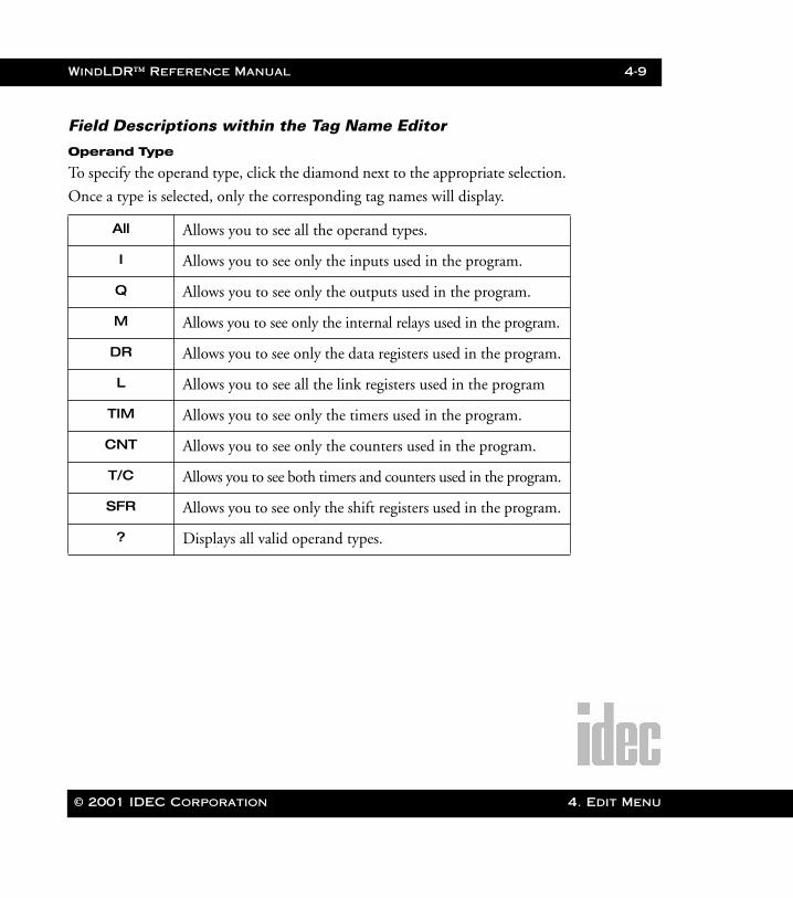
Field Descriptions within the Tag Name Editor
Operand Type
To specify the operand type, click the diamond next to the appropriate selection.
Once a type is selected, only the corresponding tag names will display.
All Allows you to see all the operand types.
I Allows you to see only the inputs used in the program.
Q Allows you to see only the outputs used in the program.
M Allows you to see only the internal relays used in the program.
DR Allows you to see only the data registers used in the program.
L Allows you to see all the link registers used in the program
TIM Allows you to see only the timers used in the program.
CNT Allows you to see only the counters used in the program.
T/C Allows you to see both timers and counters used in the program.
SFR Allows you to see only the shift registers used in the program.
? Displays all valid operand types.
© 2001 IDEC Corporation 4. Edit Menu
4-10 WindLDR™ Reference Manual
4. Edit Men
WLDR ReferenceBook Page 10 Thursday, April 5, 2001 3:36 PM
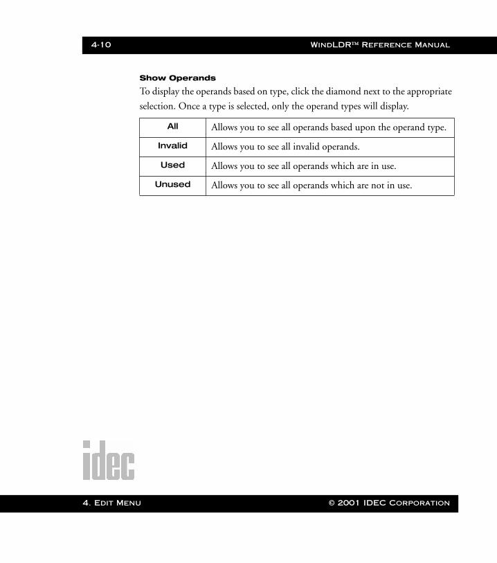
Show Operands
To display the operands based on type, click the diamond next to the appropriate
selection. Once a type is selected, only the operand types will display.
All Allows you to see all operands based upon the operand type.
Invalid Allows you to see all invalid operands.
Used Allows you to see all operands which are in use.
Unused Allows you to see all operands which are not in use.
u © 2001 IDEC Corporation
© 2001 IDEC Corporation
WLDR ReferenceBook Page 1 Thursday, April 5, 2001 3:36 PM
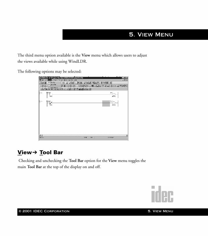
5. View Menu
The third menu option available is the View menu which allows users to adjust
the views available while using WindLDR.
The following options may be selected:
View➔ Tool Bar Checking and unchecking the Tool Bar option for the View menu toggles the
main Tool Bar at the top of the display on and off.
5. View Menu
5-2 WindLDR™ Reference Manual
5. View Men
WLDR ReferenceBook Page 2 Thursday, April 5, 2001 3:36 PM
View➔Status BarChecking and unchecking the Status Bar option from the View menu toggles
the Status Bar at the base of the display on and off.
The status bar displays the program status, PLC type, communication settings,
and the current cursor position (from left to right). The program status field dis-
plays tips about the command to which your mouse cursor currently points.
Double-clicking the PLC type field displays the PLC Selection dialog box.
Double-clicking the communications settings field displays the Communica-
tions Settings dialog box.
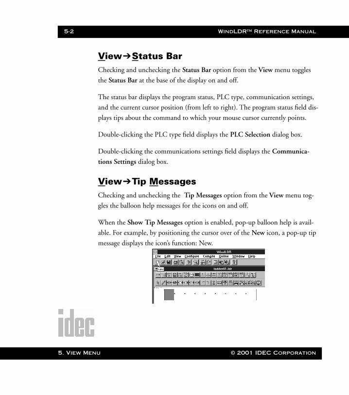
View➔Tip MessagesChecking and unchecking the Tip Messages option from the View menu tog-
gles the balloon help messages for the icons on and off.
When the Show Tip Messages option is enabled, pop-up balloon help is avail-
able. For example, by positioning the cursor over of the New icon, a pop-up tip
message displays the icon’s function: New.
u © 2001 IDEC Corporation
© 2001 IDEC Corporation
WLDR ReferenceBook Page 1 Thursday, April 5, 2001 3:36 PM
6. Configure Menu
The fourth menu option available is the Configure menu which allows you to
adjust the configurations and settings of your PLC hardware while using
WindLDR.
The following options may be selected:
6. Configure Menu
6-2 WindLDR™ Reference Manual
6. Configu
WLDR ReferenceBook Page 2 Thursday, April 5, 2001 3:36 PM
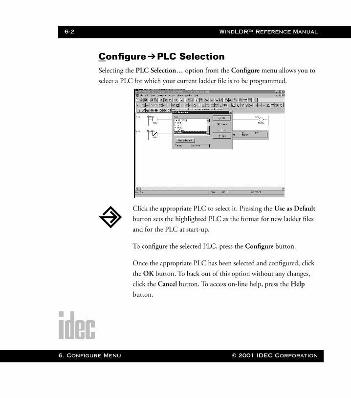
Configure ➔PLC SelectionSelecting the PLC Selection… option from the Configure menu allows you to
select a PLC for which your current ladder file is to be programmed.
Click the appropriate PLC to select it. Pressing the Use as Default
button sets the highlighted PLC as the format for new ladder files
and for the PLC at start-up.
To configure the selected PLC, press the Configure button.
Once the appropriate PLC has been selected and configured, click
the OK button. To back out of this option without any changes,
click the Cancel button. To access on-line help, press the Help
button.
re Menu © 2001 IDEC Corporation
WindLDR™ Reference Manual 6-3
WLDR ReferenceBook Page 3 Thursday, April 5, 2001 3:36 PM
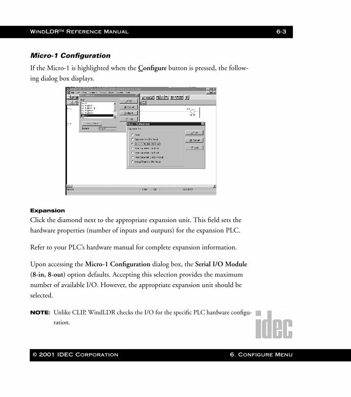
Micro-1 Configuration
If the Micro-1 is highlighted when the Configure button is pressed, the follow-
ing dialog box displays.
Expansion
Click the diamond next to the appropriate expansion unit. This field sets the
hardware properties (number of inputs and outputs) for the expansion PLC.
Refer to your PLC’s hardware manual for complete expansion information.
Upon accessing the Micro-1 Configuration dialog box, the Serial I/O Module
(8-in, 8-out) option defaults. Accepting this selection provides the maximum
number of available I/O. However, the appropriate expansion unit should be
selected.
NOTE: Unlike CLIP, WindLDR checks the I/O for the specific PLC hardware configu-
ration.
© 2001 IDEC Corporation 6. Configure Menu
6-4 WindLDR™ Reference Manual
6. Configu
WLDR ReferenceBook Page 4 Thursday, April 5, 2001 3:36 PM
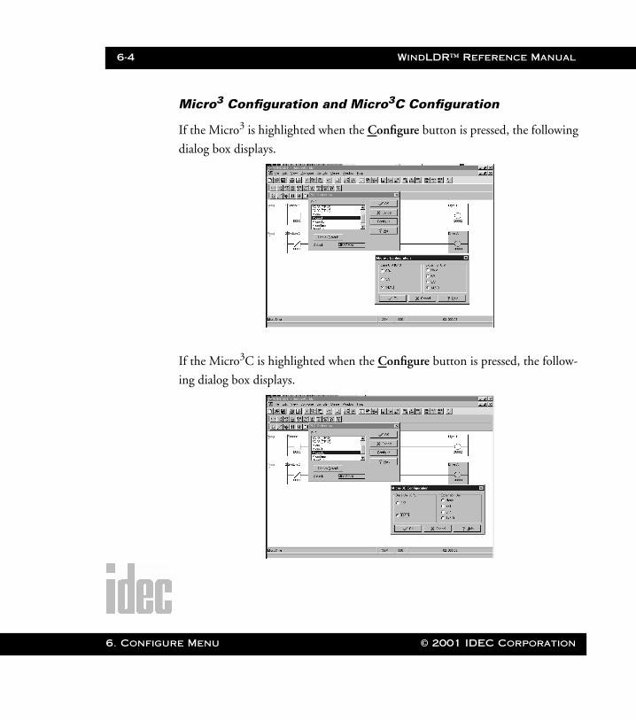
Micro3 Configuration and Micro3C Configuration
If the Micro3 is highlighted when the Configure button is pressed, the following
dialog box displays.
If the Micro3C is highlighted when the Configure button is pressed, the follow-
ing dialog box displays.
re Menu © 2001 IDEC Corporation
WindLDR™ Reference Manual 6-5
WLDR ReferenceBook Page 5 Thursday, April 5, 2001 3:36 PM
Base Unit [CPU]
Click the diamond next to the appropriate master PLC hardware properties. The
number of inputs is followed by the slash sign and then by the number of out-
puts.
Expansion Unit
Click the diamond next to the appropriate extension. This field sets the hardware
properties (number of inputs and outputs) for the expansion PLC.
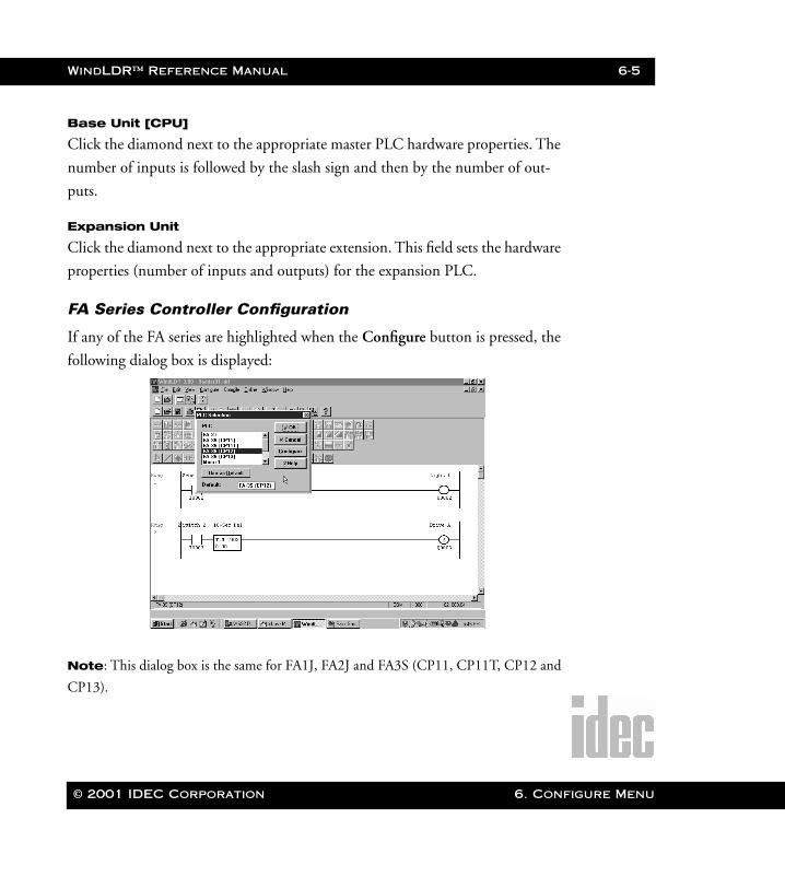
FA Series Controller Configuration
If any of the FA series are highlighted when the Configure button is pressed, the
following dialog box is displayed:
Note: This dialog box is the same for FA1J, FA2J and FA3S (CP11, CP11T, CP12 and
CP13).
© 2001 IDEC Corporation 6. Configure Menu
6-6 WindLDR™ Reference Manual
6. Configu
WLDR ReferenceBook Page 6 Thursday, April 5, 2001 3:36 PM
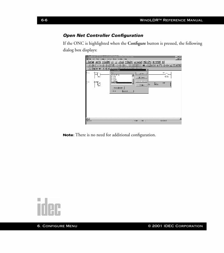
Open Net Controller Configuration
If the ONC is highlighted when the Configure button is pressed, the following
dialog box displays:
Note: There is no need for additional configuration.
re Menu © 2001 IDEC Corporation
WindLDR™ Reference Manual 6-7
WLDR ReferenceBook Page 7 Thursday, April 5, 2001 3:36 PM
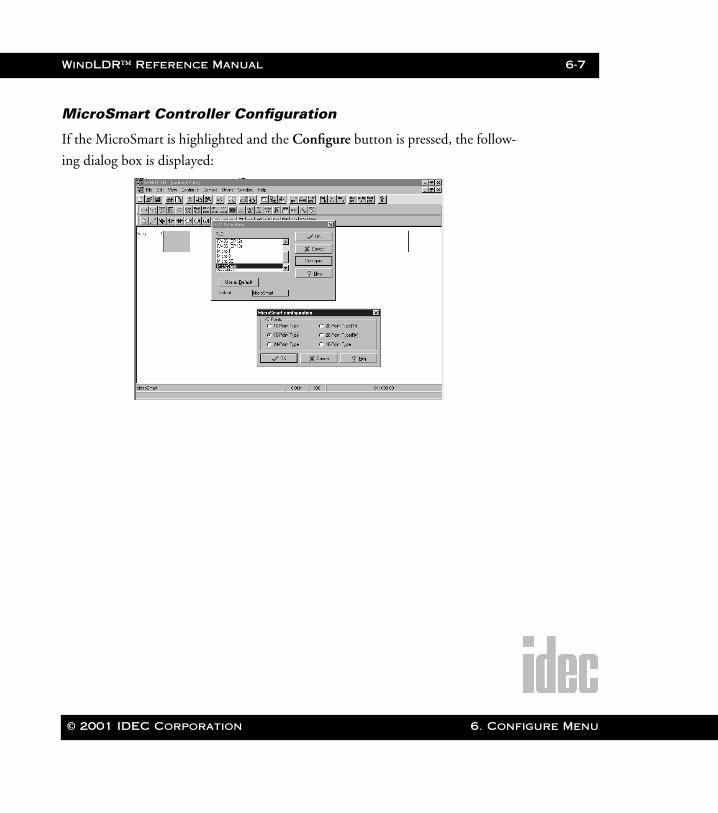
MicroSmart Controller Configuration
If the MicroSmart is highlighted and the Configure button is pressed, the follow-
ing dialog box is displayed:
© 2001 IDEC Corporation 6. Configure Menu
6-8 WindLDR™ Reference Manual
6. Configu
WLDR ReferenceBook Page 8 Thursday, April 5, 2001 3:36 PM
Configure ➔Function Area Settings…Selecting the Function Area Settings… option from the Configure menu allows
you to set internal functional settings for the current PLC (as selected in the PLC
selection… option of the Configure menu).
Click the appropriate PLC settings as described in the following
field descriptions. Clicking an option selects it. To deselect the
option, click another option and click OK.
Once the appropriate function area settings have been selected, click
the OK button. To back out of this option without any changes,
click the Cancel button. To access on-line help, press the Help
button.
To return to the default settings for the PLC, click the Default but-
ton at any time.
re Menu © 2001 IDEC Corporation
WindLDR™ Reference Manual 6-9
WLDR ReferenceBook Page 9 Thursday, April 5, 2001 3:36 PM
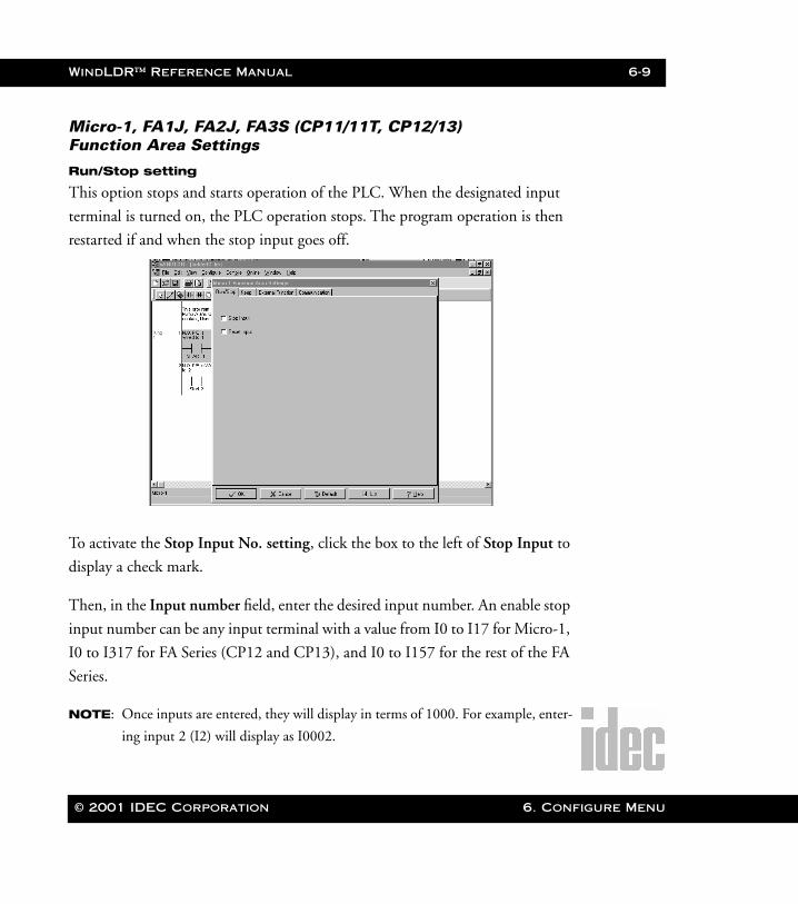
Micro-1, FA1J, FA2J, FA3S (CP11/11T, CP12/13)Function Area Settings
Run/Stop setting
This option stops and starts operation of the PLC. When the designated input
terminal is turned on, the PLC operation stops. The program operation is then
restarted if and when the stop input goes off.
To activate the Stop Input No. setting, click the box to the left of Stop Input to
display a check mark.
Then, in the Input number field, enter the desired input number. An enable stop
input number can be any input terminal with a value from I0 to I17 for Micro-1,
I0 to I317 for FA Series (CP12 and CP13), and I0 to I157 for the rest of the FA
Series.
NOTE: Once inputs are entered, they will display in terms of 1000. For example, enter-
ing input 2 (I2) will display as I0002.
© 2001 IDEC Corporation 6. Configure Menu
6-10 WindLDR™ Reference Manual
6. Configu
WLDR ReferenceBook Page 10 Thursday, April 5, 2001 3:36 PM
If the Default button is pressed, this and all other corresponding options turn
off. In other words, all settings will revert back to the original defaults.
If an invalid stop input number is entered, an error message will display. A valid
input number must be entered or the invalid number erased.
Reset input No. setting
This option resets the operation of the PLC when the designated input terminal
is activated. The program operation will restart if the input goes off while the
start input is on. When the reset input is turned ON, the reset input has priority
over the stop input.
To activate the Reset input No. setting, click the box to the left of Enable reset
input to display a check mark.
Then, in the Input number field, enter the desired input number. An enable
reset input number can have a value from I0 to I17 for Micro-1, I0 to I317 for
FA Series (CP12 and CP13), and I0 to I157 for the rest of the FA Series. Input
numbers I8 and I9 are not valid.
NOTE: Once inputs are entered, they will display in terms of 1000. For example, enter-
ing input 2 (I2) will display as I0002.
WARNING: If the Default button is pressed, this and all other corresponding options
turn off. In other words, all settings will revert back to the original defaults.
If an invalid reset input number is entered, an error message will display. A valid
input number must be entered or the invalid number will be erased.
NOTE: Input numbers ending in 8 or 9 are not valid.
re Menu © 2001 IDEC Corporation
WindLDR™ Reference Manual 6-11
WLDR ReferenceBook Page 11 Thursday, April 5, 2001 3:36 PM
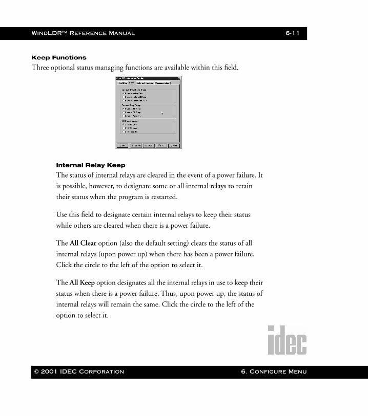
Keep Functions
Three optional status managing functions are available within this field.
Internal Relay Keep
The status of internal relays are cleared in the event of a power failure. It
is possible, however, to designate some or all internal relays to retain
their status when the program is restarted.
Use this field to designate certain internal relays to keep their status
while others are cleared when there is a power failure.
The All Clear option (also the default setting) clears the status of all
internal relays (upon power up) when there has been a power failure.
Click the circle to the left of the option to select it.
The All Keep option designates all the internal relays in use to keep their
status when there is a power failure. Thus, upon power up, the status of
internal relays will remain the same. Click the circle to the left of the
option to select it.
© 2001 IDEC Corporation 6. Configure Menu
6-12 WindLDR™ Reference Manual
6. Configu
WLDR ReferenceBook Page 12 Thursday, April 5, 2001 3:36 PM
The Keep to option retains the status of all internal relays (upon power
up) prior to the relay entered in the accompanying field. Click the circle
to the left of the option to select it. Then enter the appropriate internal
relay number in the field to the right. For example, if M100 is entered,
then internal relays M0 – M100 will retain their current states upon
power up. Internal relays M101 and up will be reset.
Counter Keep
Counter values are cleared in the event of a power failure. It is possible,
however, to designate some counters to retain their current count when
the program is restarted.
Use this field to designate a range of incremental counters which will
keep the current count, while others are cleared when the program is
restarted.
The All Clear option (also the default setting) clears the current count of
all the counters (upon power up) when there has been a power failure.
Click the circle to the left of the option to select it.
The All Keep option designates all counters in use to keep their counts
when there is a power failure. Thus, upon power up, the count values of
counters will remain the same. Click the circle to the left of the option
to select it.
The Keep to option retains the counted values (upon power up) of all
counters prior to the counter entered in the accompanying field. Click
the circle to the left of the option to select it. Then, enter the appropri-
re Menu © 2001 IDEC Corporation

WindLDR™ Reference Manual 6-13
WLDR ReferenceBook Page 13 Thursday, April 5, 2001 3:36 PM
ate counter number in the field to the right. For example, if C9 is
entered, then counters C0 – C9 will retain their current states upon
power up. Counters C10 and up will be reset.
SFR Keep
Shift register bits are cleared in the event of a power failure. It is possible,
however, to designate a range of shift register bits to retain their types
when the program is restarted.
Use this field to designate a range of shift register bits which will keep
their current status, while others are cleared when the program is
restarted.
The All Clear option (also the default setting) clears all of the current
shift register bits (upon power up) when there has been a power failure.
Click the circle to the left of the option to select it.
The All Keep option designates all shift registers in use to keep their sta-
tus when there is a power failure. Thus, upon power up, the shift register
bits will retain their states (either 0 or 1). Click the circle to the left of
the option to select it.
The Keep to option retains the shift register bits (upon power up) of all
registers prior to the number entered in the accompanying field. Click
the circle to the left of the option to select it. Then enter the appropriate
register bit number in the field to the right. For example, if R100 is
entered, then shift registers R0 – R100 will retain their current states
upon power up. Shift registers R101 and up will be reset.
© 2001 IDEC Corporation 6. Configure Menu
6-14 WindLDR™ Reference Manual
6. Configu
WLDR ReferenceBook Page 14 Thursday, April 5, 2001 3:36 PM
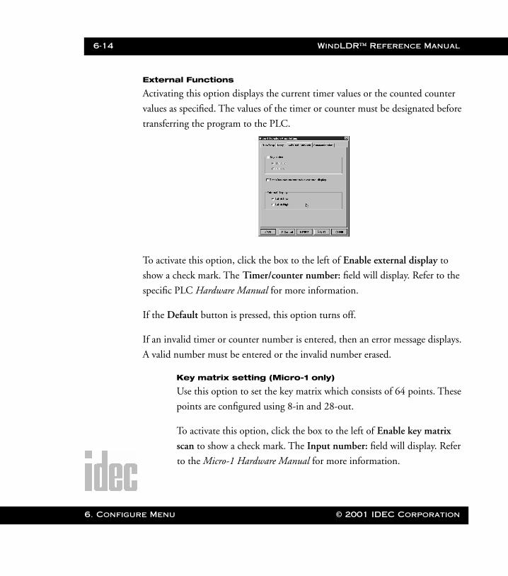
External Functions
Activating this option displays the current timer values or the counted counter
values as specified. The values of the timer or counter must be designated before
transferring the program to the PLC.
To activate this option, click the box to the left of Enable external display to
show a check mark. The Timer/counter number: field will display. Refer to the
specific PLC Hardware Manual for more information.
If the Default button is pressed, this option turns off.
If an invalid timer or counter number is entered, then an error message displays.
A valid number must be entered or the invalid number erased.
Key matrix setting (Micro-1 only)
Use this option to set the key matrix which consists of 64 points. These
points are configured using 8-in and 28-out.
To activate this option, click the box to the left of Enable key matrix
scan to show a check mark. The Input number: field will display. Refer
to the Micro-1 Hardware Manual for more information.
re Menu © 2001 IDEC Corporation
WindLDR™ Reference Manual 6-15
WLDR ReferenceBook Page 15 Thursday, April 5, 2001 3:36 PM
Then, in the Input number: field, select the desired range: either I00 -
I07 or I10 - I17.
If the Default button is pressed, this option turns off.
External Display Latch condition setting
Use this option to set the latch condition for the PLC when using the
external display function.
To activate this option, click the circle to the left of either the Low latch
or High latch option accordingly.
If the Default button is pressed, this option will be turned off entirely.
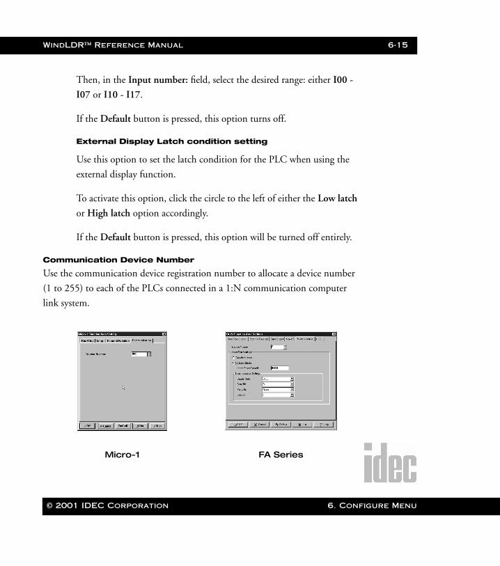
Communication Device Number
Use the communication device registration number to allocate a device number
(1 to 255) to each of the PLCs connected in a 1:N communication computer
link system.
Micro-1 FA Series
© 2001 IDEC Corporation 6. Configure Menu
6-16 WindLDR™ Reference Manual
6. Configu
WLDR ReferenceBook Page 16 Thursday, April 5, 2001 3:36 PM
Loader Port Settings
There are 2 selections: Standard Mode and Optional Mode. The
Optional Mode allows you to select the desired communication settings
and to switch to the setting automatically with a designated input.
NOTE:The List icon displays the PLC functions and details in a notepad file for-
mat.
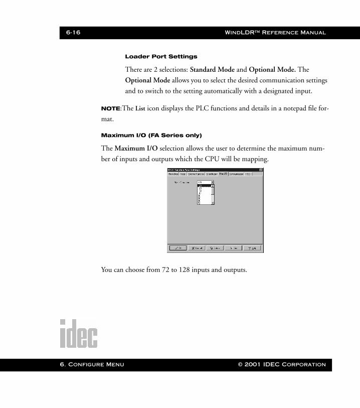
Maximum I/O (FA Series only)
The Maximum I/O selection allows the user to determine the maximum num-
ber of inputs and outputs which the CPU will be mapping.
You can choose from 72 to 128 inputs and outputs.
re Menu © 2001 IDEC Corporation
WindLDR™ Reference Manual 6-17
WLDR ReferenceBook Page 17 Thursday, April 5, 2001 3:36 PM
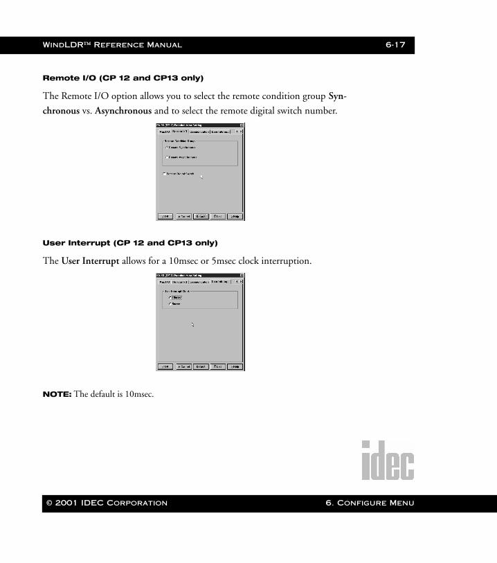
Remote I/O (CP 12 and CP13 only)
The Remote I/O option allows you to select the remote condition group Syn-
chronous vs. Asynchronous and to select the remote digital switch number.
User Interrupt (CP 12 and CP13 only)
The User Interrupt allows for a 10msec or 5msec clock interruption.
NOTE: The default is 10msec.
© 2001 IDEC Corporation 6. Configure Menu
6-18 WindLDR™ Reference Manual
6. Configu
WLDR ReferenceBook Page 18 Thursday, April 5, 2001 3:36 PM
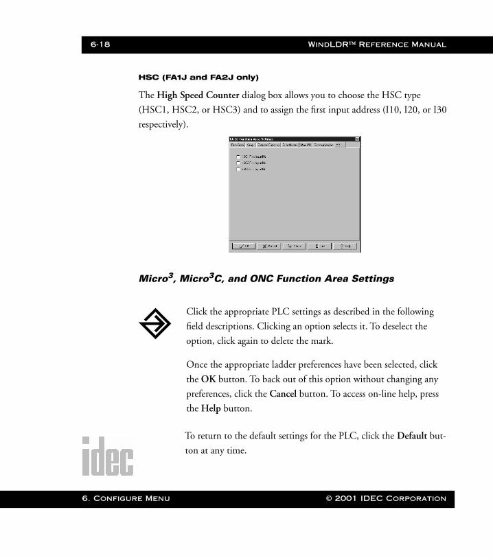
HSC (FA1J and FA2J only)
The High Speed Counter dialog box allows you to choose the HSC type
(HSC1, HSC2, or HSC3) and to assign the first input address (I10, I20, or I30
respectively).
Micro3, Micro3C, and ONC Function Area Settings
To return to the default settings for the PLC, click the Default but-
ton at any time.
Click the appropriate PLC settings as described in the following
field descriptions. Clicking an option selects it. To deselect the
option, click again to delete the mark.
Once the appropriate ladder preferences have been selected, click
the OK button. To back out of this option without changing any
preferences, click the Cancel button. To access on-line help, press
the Help button.
re Menu © 2001 IDEC Corporation
WindLDR™ Reference Manual 6-19
WLDR ReferenceBook Page 19 Thursday, April 5, 2001 3:36 PM
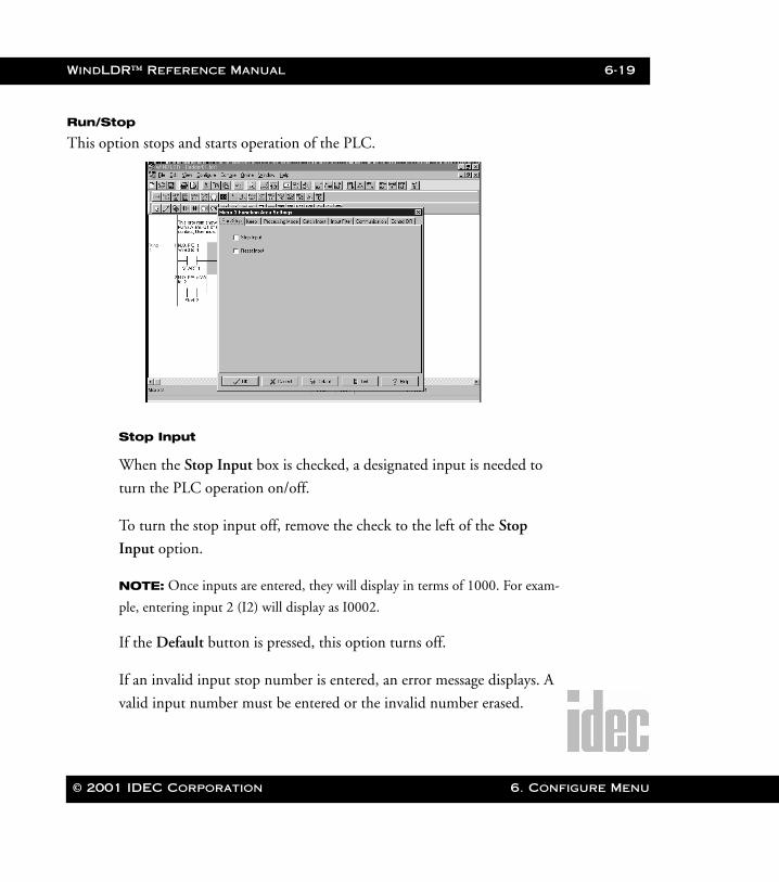
Run/Stop
This option stops and starts operation of the PLC.
Stop Input
When the Stop Input box is checked, a designated input is needed to
turn the PLC operation on/off.
To turn the stop input off, remove the check to the left of the Stop
Input option.
NOTE: Once inputs are entered, they will display in terms of 1000. For exam-
ple, entering input 2 (I2) will display as I0002.
If the Default button is pressed, this option turns off.
If an invalid input stop number is entered, an error message displays. A
valid input number must be entered or the invalid number erased.
© 2001 IDEC Corporation 6. Configure Menu
6-20 WindLDR™ Reference Manual
6. Configu
WLDR ReferenceBook Page 20 Thursday, April 5, 2001 3:36 PM
Reset Input
This option stops the operation of the Micro3, Micro3C, and ONC and
resets the counters and internal relays.
To turn the reset input off, check the box to the left of the Reset Input
option.
If the Default button is pressed, this option turns off.
If an invalid input stop number is entered, an error message will display.
A valid input number must be entered or the invalid number erased.
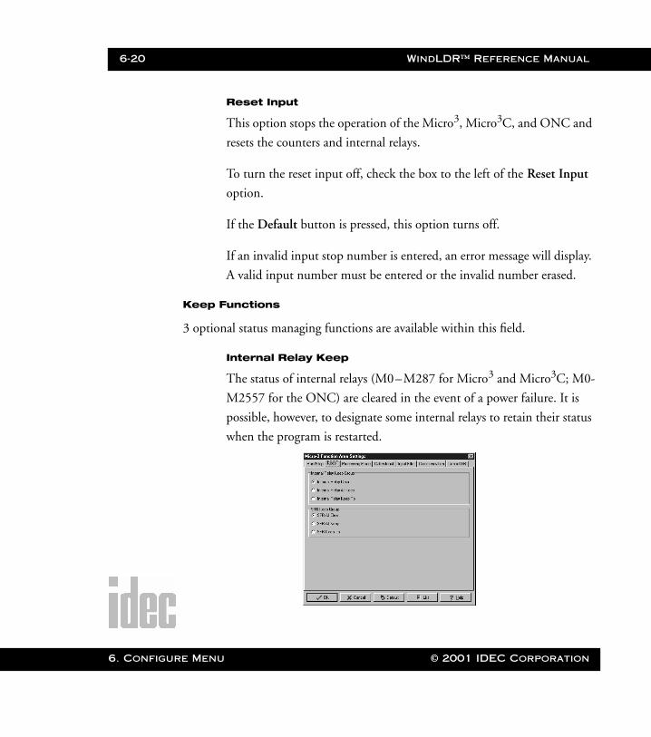
Keep Functions
3 optional status managing functions are available within this field.
Internal Relay Keep
The status of internal relays (M0–M287 for Micro3 and Micro3C; M0-
M2557 for the ONC) are cleared in the event of a power failure. It is
possible, however, to designate some internal relays to retain their status
when the program is restarted.
re Menu © 2001 IDEC Corporation
WindLDR™ Reference Manual 6-21
WLDR ReferenceBook Page 21 Thursday, April 5, 2001 3:36 PM
The All Clear option (also the default setting) clears the status of all
internal relays, upon power up, when there has been a power failure.
Check the box to the left of this option to select it.
The All Keep option designates all the internal relays in use to keep their
status when there is a power failure. Thus, upon power up, the status of
internal relays (M0–M287 for Micro3 and Micro3C; M0-M2557 for
the ONC) will remain the same. Click the circle to the left of this option
to select it.
The Set option retains the status of all internal relays (upon power up)
prior to the relay entered in the accompanying field. Click the circle to
the left of this option to select it. Then enter the appropriate internal
relay number in the field to the right. Enter the range to set the bound-
ary of internal relays which will retain their current states upon power
up.
NOTE: Input numbers ending in 8 or 9 are not valid.
SFR Keep
Shift register bits (R0–R63 for Micro3 and Micro3C; R0-R254 for the
ONC) are cleared in the event of a power failure. It is possible, however,
to designate a range of shift register bits to retain their types when the
program is restarted.
The All Clear option (also the default setting) clears all of the current
shift register bits, upon power up, when there has been a power failure.
Click the diamond to the left of this option to select it.
© 2001 IDEC Corporation 6. Configure Menu
6-22 WindLDR™ Reference Manual
6. Configu
WLDR ReferenceBook Page 22 Thursday, April 5, 2001 3:36 PM
The All Keep option designates all shift registers in use to keep their sta-
tus when there is a power failure. Thus, upon power up, the shift register
bits will retain their states (either 0 or 1). Click the diamond to the left
of this option to select it.
The Set option retains the shift register bits (upon power up) of all regis-
ters prior to the number entered in the accompanying field. Click the
diamond to the left of this option to select it. Then enter the appropriate
register number in the field to the right. Enter the range to set the
boundary of shift register bits which will retain their current states upon
power up.
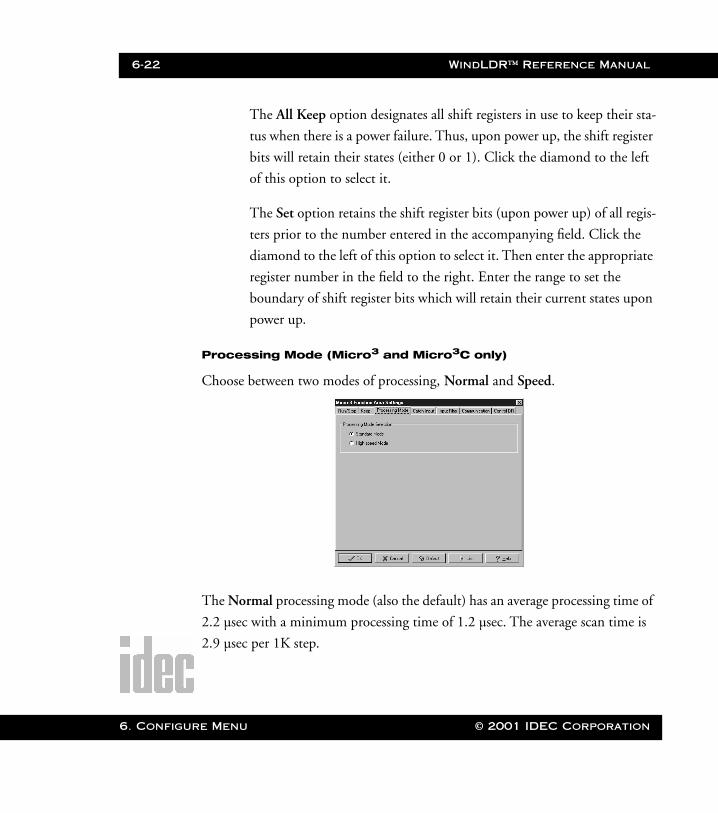
Processing Mode (Micro3 and Micro3C only)
Choose between two modes of processing, Normal and Speed.
The Normal processing mode (also the default) has an average processing time of
2.2 µsec with a minimum processing time of 1.2 µsec. The average scan time is
2.9 µsec per 1K step.
re Menu © 2001 IDEC Corporation
WindLDR™ Reference Manual 6-23
WLDR ReferenceBook Page 23 Thursday, April 5, 2001 3:36 PM
Use the Speed (or high-speed) processing mode as a sensor controller or when
executing a user program at high speed is necessary. The average processing time
is 0.45 µsec with a minimum processing time of 0.2 µsec. The average scan time
is 400 µsec per 100 steps.
NOTE: In high-speed mode, control data registers D90 – D99 cannot be used.
NOTE: When high-speed mode is selected for the Micro3 series, the I/O expansion link
and data link functions cannot be used.
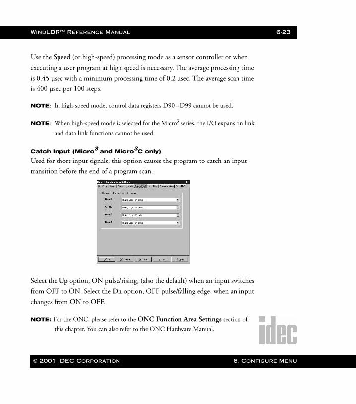
Catch Input (Micro3 and Micro3C only)
Used for short input signals, this option causes the program to catch an input
transition before the end of a program scan.
Select the Up option, ON pulse/rising, (also the default) when an input switches
from OFF to ON. Select the Dn option, OFF pulse/falling edge, when an input
changes from ON to OFF.
NOTE: For the ONC, please refer to the ONC Function Area Settings section of
this chapter. You can also refer to the ONC Hardware Manual.
© 2001 IDEC Corporation 6. Configure Menu
6-24 WindLDR™ Reference Manual
6. Configu
WLDR ReferenceBook Page 24 Thursday, April 5, 2001 3:36 PM
Catch inputs are divided into four groups.
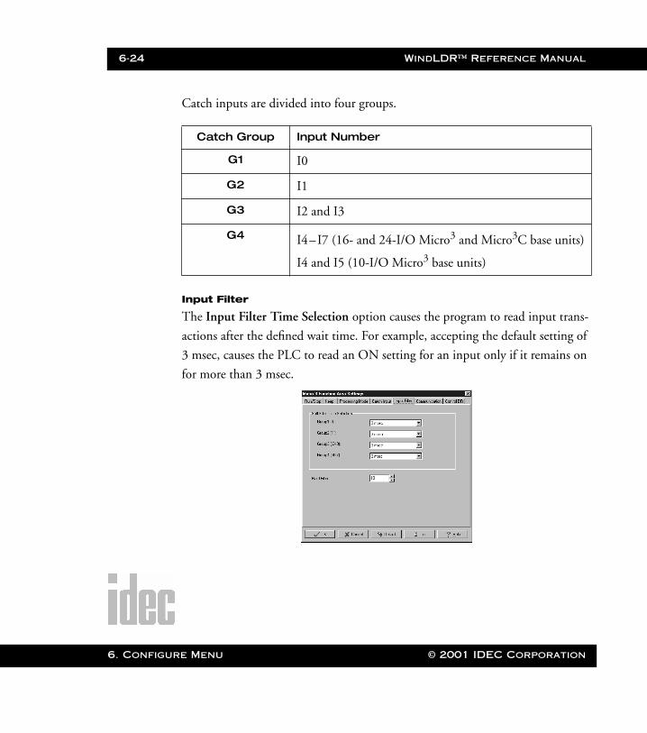
Input Filter
The Input Filter Time Selection option causes the program to read input trans-
actions after the defined wait time. For example, accepting the default setting of
3 msec, causes the PLC to read an ON setting for an input only if it remains on
for more than 3 msec.
Catch Group Input Number
G1 I0
G2 I1
G3 I2 and I3
G4 I4–I7 (16- and 24-I/O Micro3 and Micro3C base units)
I4 and I5 (10-I/O Micro3 base units)
re Menu © 2001 IDEC Corporation
WindLDR™ Reference Manual 6-25
WLDR ReferenceBook Page 25 Thursday, April 5, 2001 3:36 PM
Soft Filter:
The soft filter, divided into four groups, refers to the software-dependent
time filters. This allows you some flexibility to define different input
wait times for different inputs. Select among four wait time spans for
each group: 0, 3, 7, or 10 msec.
Hard Filter:
The hard filter refers to the hardware-dependent time filters. This allows
you to choose a separate time delay for the PLC hardware. Using the up
and down arrow scroll bars, select a time delay from 0 to 255 msec. The
default setting is 10 msec.
Soft Group Input Number
G1 I0
G2 I1
G3 I2 and I3
G4 I4 through I7
© 2001 IDEC Corporation 6. Configure Menu

6-26 WindLDR™ Reference Manual
6. Configu
WLDR ReferenceBook Page 26 Thursday, April 5, 2001 3:36 PM
Communication
Use the Communication Device Number field to allocate a device number (1 to
31) to each of the Micro3 or Micro3C PLCs connected in a 1:N communication
computer link system.
NOTE: This option is only applicable when there is more than one PLC connected to
your PC.
Click the up and down arrow scroll bars to select the desired device number.
If the Default button is pressed, this option resets to 0.
Communication Format Selection
Select between the default communications mode settings and optional
settings. The communication mode settings determine how the PLC
and PC will communicate with each other.
NOTE:Check your PLC’s hardware manual to determine the appropriate com-
munication mode settings to use.
re Menu © 2001 IDEC Corporation

WindLDR™ Reference Manual 6-27
WLDR ReferenceBook Page 27 Thursday, April 5, 2001 3:36 PM
To accept the default settings (according to the following table), leave
the diamond to the left of the Standard Mode option clicked. To set up
your own communication mode settings, click the diamond to the left
of the Optional Mode option.
Standard Mode (default)
Optional
Baud Rate 9600 bps 1200 bps, 2400 bps, 4800 bps,
9600 bps, 19200 bps
Data Bits 7 7, 8
Stop Bits 1 1, 2
Parity Even None, Odd, Even
Terminator Code
CR (carriage return) CR (carriage return),
CR/LF (carriage return/line feed)
Receive Time-Out:
50 msec Select within the range of 10 msec
to 255 msec
Input number:
N/A Defined by the type of inputs on
the PLC being used
© 2001 IDEC Corporation 6. Configure Menu
6-28 WindLDR™ Reference Manual
6. Configu
WLDR ReferenceBook Page 28 Thursday, April 5, 2001 3:36 PM
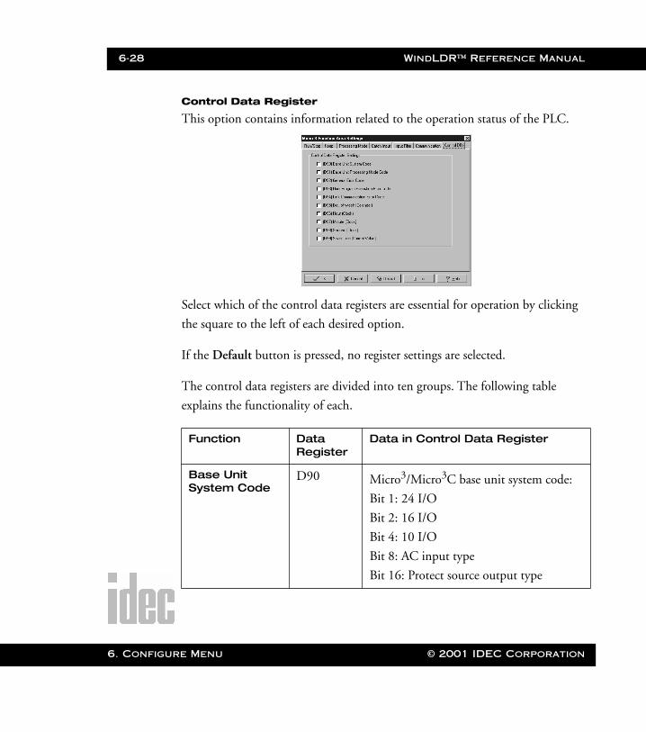
Control Data Register
This option contains information related to the operation status of the PLC.
Select which of the control data registers are essential for operation by clicking
the square to the left of each desired option.
If the Default button is pressed, no register settings are selected.
The control data registers are divided into ten groups. The following table
explains the functionality of each.
Function Data Register
Data in Control Data Register
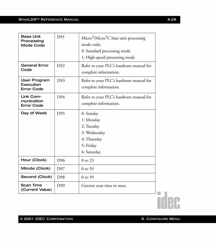
Base Unit System Code
D90 Micro3/Micro3C base unit system code:
Bit 1: 24 I/O
Bit 2: 16 I/O
Bit 4: 10 I/O
Bit 8: AC input type
Bit 16: Protect source output type
re Menu © 2001 IDEC Corporation
WindLDR™ Reference Manual 6-29
WLDR ReferenceBook Page 29 Thursday, April 5, 2001 3:36 PM
Base Unit Processing Mode Code
D91 Micro3/Micro3C base unit processing
mode code:
0: Standard processing mode
1: High-speed processing mode
General Error Code
D92 Refer to your PLC’s hardware manual for
complete information.
User Program Execution Error Code
D93 Refer to your PLC’s hardware manual for
complete information.
Link Com-munication Error Code
D94 Refer to your PLC’s hardware manual for
complete information.
Day of Week D95 0: Sunday
1: Monday
2: Tuesday
3: Wednesday
4: Thursday
5: Friday
6: Saturday
Hour (Clock) D96 0 to 23
Minute (Clock) D97 0 to 59
Second (Clock) D98 0 to 59
Scan Time (Current Value)
D99 Current scan time in msec
© 2001 IDEC Corporation 6. Configure Menu
6-30 WindLDR™ Reference Manual
6. Configu
WLDR ReferenceBook Page 30 Thursday, April 5, 2001 3:36 PM
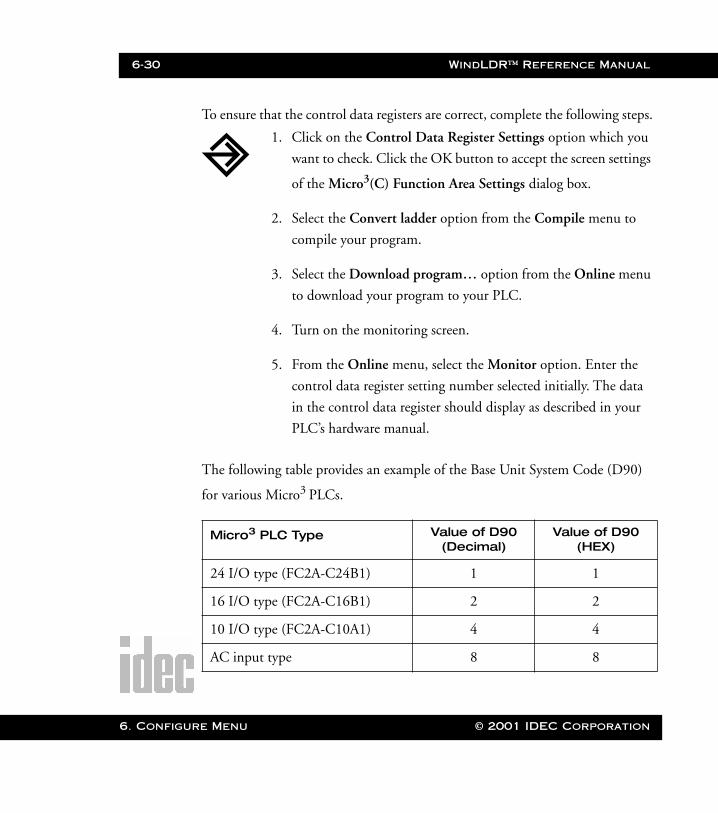
To ensure that the control data registers are correct, complete the following steps.
The following table provides an example of the Base Unit System Code (D90)
for various Micro3 PLCs.
Micro3 PLC Type Value of D90 (Decimal)
Value of D90 (HEX)
24 I/O type (FC2A-C24B1) 1 1
16 I/O type (FC2A-C16B1) 2 2
10 I/O type (FC2A-C10A1) 4 4
AC input type 8 8
1. Click on the Control Data Register Settings option which you
want to check. Click the OK button to accept the screen settings
of the Micro3(C) Function Area Settings dialog box.
2. Select the Convert ladder option from the Compile menu to
compile your program.
3. Select the Download program… option from the Online menu
to download your program to your PLC.
4. Turn on the monitoring screen.
5. From the Online menu, select the Monitor option. Enter the
control data register setting number selected initially. The data
in the control data register should display as described in your
PLC’s hardware manual.
re Menu © 2001 IDEC Corporation
WindLDR™ Reference Manual 6-31
WLDR ReferenceBook Page 31 Thursday, April 5, 2001 3:36 PM
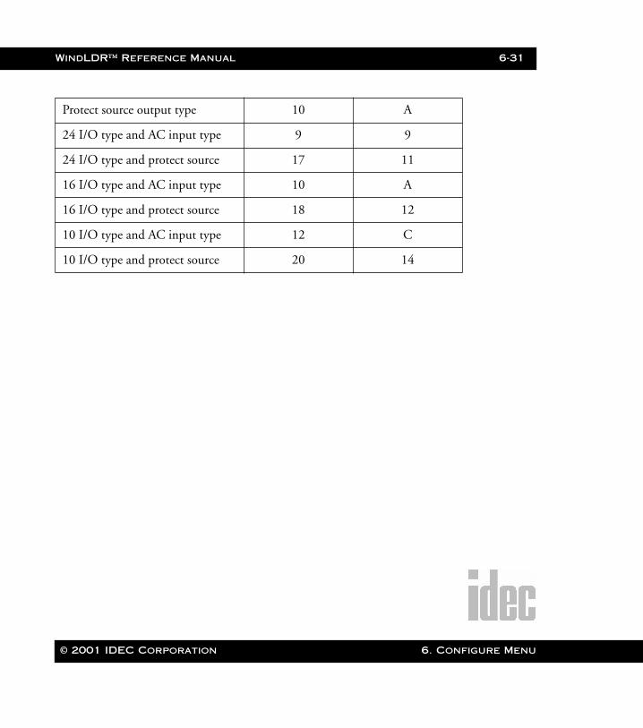
Protect source output type 10 A
24 I/O type and AC input type 9 9
24 I/O type and protect source 17 11
16 I/O type and AC input type 10 A
16 I/O type and protect source 18 12
10 I/O type and AC input type 12 C
10 I/O type and protect source 20 14
© 2001 IDEC Corporation 6. Configure Menu
6-32 WindLDR™ Reference Manual
6. Configu
WLDR ReferenceBook Page 32 Thursday, April 5, 2001 3:36 PM
re Menu © 2001 IDEC Corporation
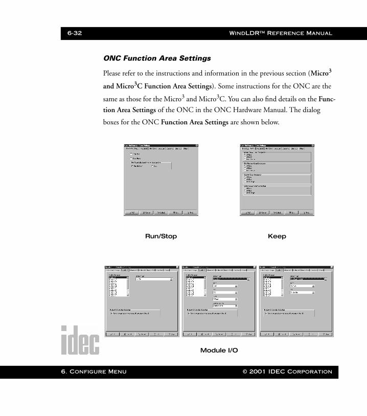
ONC Function Area Settings
Please refer to the instructions and information in the previous section (Micro3
and Micro3C Function Area Settings). Some instructions for the ONC are the
same as those for the Micro3 and Micro3C. You can also find details on the Func-
tion Area Settings of the ONC in the ONC Hardware Manual. The dialog
boxes for the ONC Function Area Settings are shown below.
Run/Stop Keep
Module I/O
WindLDR™ Reference Manual 6-33
WLDR ReferenceBook Page 33 Thursday, April 5, 2001 3:36 PM
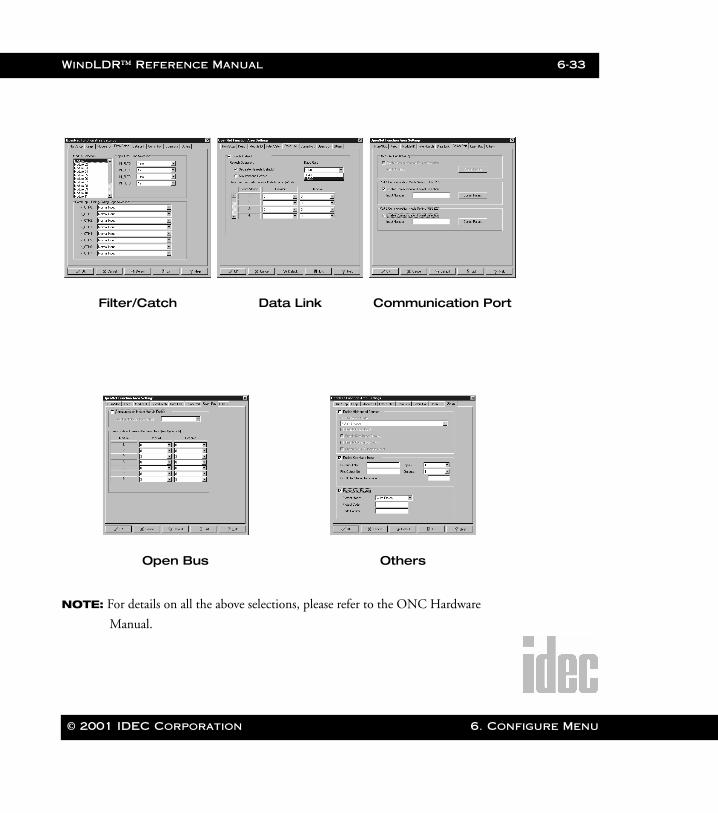
NOTE: For details on all the above selections, please refer to the ONC Hardware
Manual.
Filter/Catch Data Link Communication Port
Open Bus Others
© 2001 IDEC Corporation 6. Configure Menu
6-34 WindLDR™ Reference Manual
6. Configu
WLDR ReferenceBook Page 34 Thursday, April 5, 2001 3:36 PM
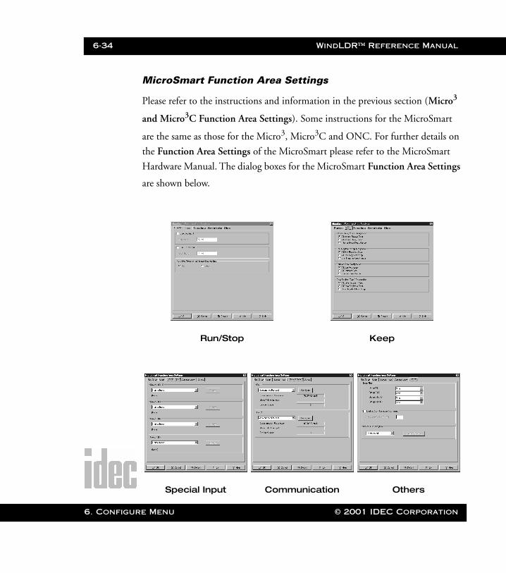
MicroSmart Function Area Settings
Please refer to the instructions and information in the previous section (Micro3
and Micro3C Function Area Settings). Some instructions for the MicroSmart
are the same as those for the Micro3, Micro3C and ONC. For further details on
the Function Area Settings of the MicroSmart please refer to the MicroSmart
Hardware Manual. The dialog boxes for the MicroSmart Function Area Settings
are shown below.
Run/Stop Keep
Special Input Communication Others
re Menu © 2001 IDEC Corporation
WindLDR™ Reference Manual 6-35
WLDR ReferenceBook Page 35 Thursday, April 5, 2001 3:36 PM
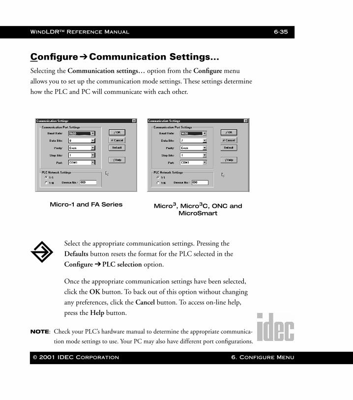
Configure ➔Communication Settings…Selecting the Communication settings… option from the Configure menu
allows you to set up the communication mode settings. These settings determine
how the PLC and PC will communicate with each other.
NOTE: Check your PLC’s hardware manual to determine the appropriate communica-
tion mode settings to use. Your PC may also have different port configurations.
Micro-1 and FA Series Micro3, Micro3C, ONC and MicroSmart
Select the appropriate communication settings. Pressing the
Defaults button resets the format for the PLC selected in the
Configure ➔ PLC selection option.
Once the appropriate communication settings have been selected,
click the OK button. To back out of this option without changing
any preferences, click the Cancel button. To access on-line help,
press the Help button.
© 2001 IDEC Corporation 6. Configure Menu
6-36 WindLDR™ Reference Manual
6. Configu
WLDR ReferenceBook Page 36 Thursday, April 5, 2001 3:36 PM
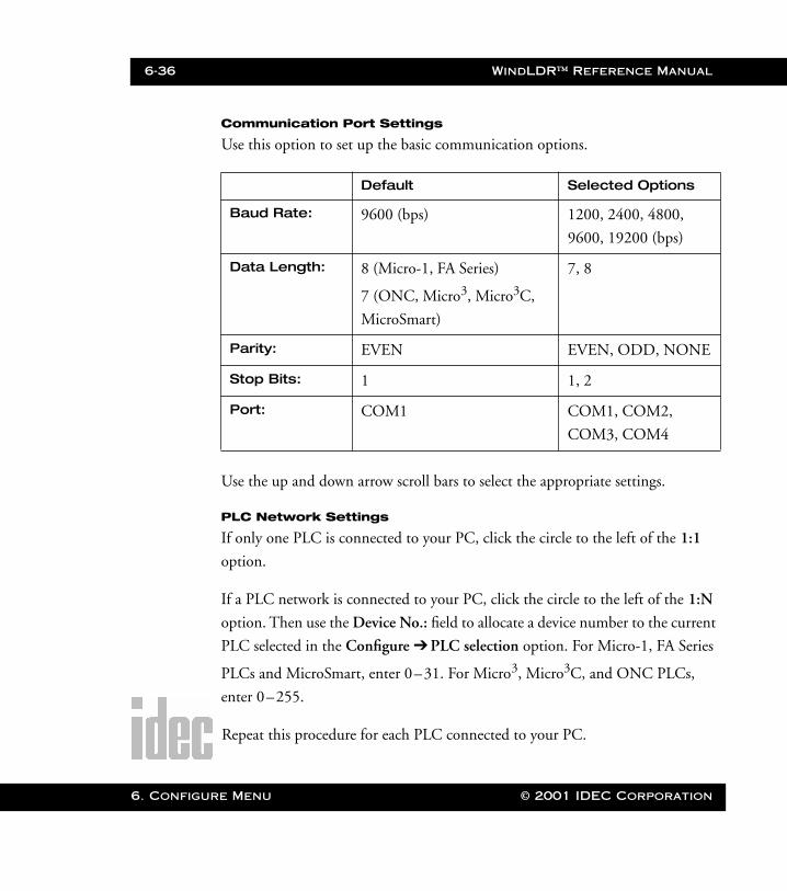
Communication Port Settings
Use this option to set up the basic communication options.
Use the up and down arrow scroll bars to select the appropriate settings.
PLC Network Settings
If only one PLC is connected to your PC, click the circle to the left of the 1:1
option.
If a PLC network is connected to your PC, click the circle to the left of the 1:N
option. Then use the Device No.: field to allocate a device number to the current
PLC selected in the Configure ➔ PLC selection option. For Micro-1, FA Series
PLCs and MicroSmart, enter 0–31. For Micro3, Micro3C, and ONC PLCs,
enter 0–255.
Repeat this procedure for each PLC connected to your PC.
Default Selected Options
Baud Rate: 9600 (bps) 1200, 2400, 4800,
9600, 19200 (bps)
Data Length: 8 (Micro-1, FA Series)
7 (ONC, Micro3, Micro3C,
MicroSmart)
7, 8
Parity: EVEN EVEN, ODD, NONE
Stop Bits: 1 1, 2
Port: COM1 COM1, COM2,
COM3, COM4
re Menu © 2001 IDEC Corporation
WindLDR™ Reference Manual 6-37
WLDR ReferenceBook Page 37 Thursday, April 5, 2001 3:36 PM
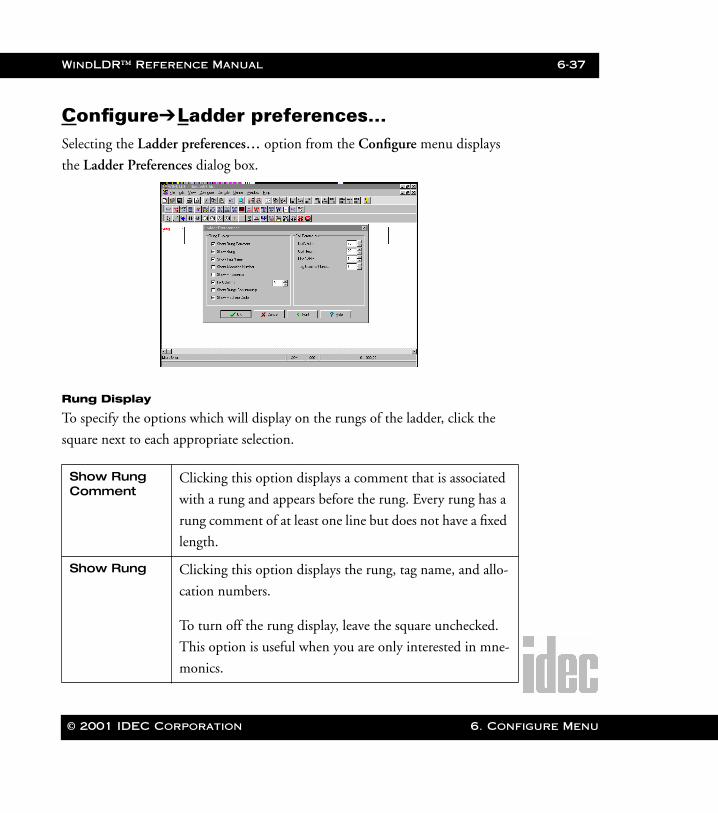
Configure➔Ladder preferences…Selecting the Ladder preferences… option from the Configure menu displays
the Ladder Preferences dialog box.
Rung Display
To specify the options which will display on the rungs of the ladder, click the
square next to each appropriate selection.
Show Rung Comment
Clicking this option displays a comment that is associated
with a rung and appears before the rung. Every rung has a
rung comment of at least one line but does not have a fixed
length.
Show Rung Clicking this option displays the rung, tag name, and allo-
cation numbers.
To turn off the rung display, leave the square unchecked.
This option is useful when you are only interested in mne-
monics.
© 2001 IDEC Corporation 6. Configure Menu
6-38 WindLDR™ Reference Manual
6. Configu
WLDR ReferenceBook Page 38 Thursday, April 5, 2001 3:36 PM
Coil Parameters
To specify the parameters of each coil on the rung, enter an appropriate figure in
each field. You may click the up and down arrows to select the figures as well.
Show Tag Name
Clicking this option displays the tag name under each coil.
Normally, only the tag name is displayed.
Show Allocation Number
Clicking this option displays the allocation number under
each coil.
Show Mnemonics
Clicking this option displays the ladder mnemonics under
each coil after compiling.
Fix Columns Clicking this option and setting the number of fix columns
will set the rungs to the number of columns specified.
Show Rungs Continuously
Clicking this option displays left and right power rails con-
tinuously.
Show Machine Code
Clicking the Show Mnemonics and this option displays
the machine code under each coil after compiling.
Coil Width Enter the width of each coil in pixels.
Coil Height Enter the height of each coil in pixels.
Line Width Enter the width of each line in pixels.
Tag Comment Lines
Enter the number of tag comment lines to be allowed with
each tag name. This number can be up to 100 lines, however
it is recommended that you restrict the tag comment lines to 4
lines. This number is fixed until the number is changed again
within this field.
re Menu © 2001 IDEC Corporation
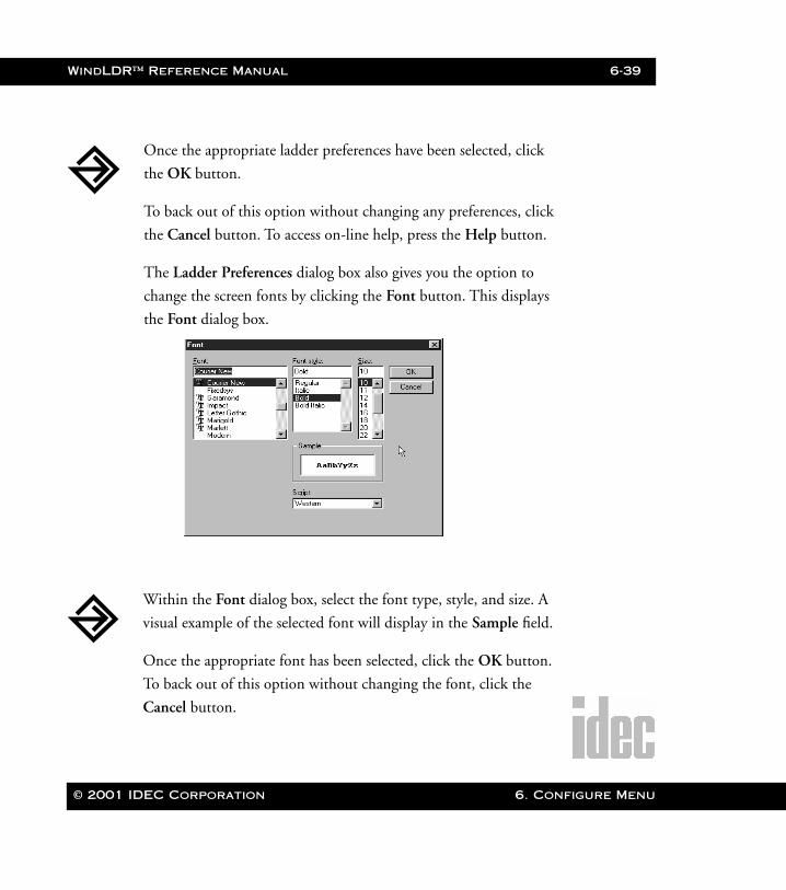
WindLDR™ Reference Manual 6-39
WLDR ReferenceBook Page 39 Thursday, April 5, 2001 3:36 PM
Once the appropriate ladder preferences have been selected, click
the OK button.
To back out of this option without changing any preferences, click
the Cancel button. To access on-line help, press the Help button.
The Ladder Preferences dialog box also gives you the option to
change the screen fonts by clicking the Font button. This displays
the Font dialog box.
Within the Font dialog box, select the font type, style, and size. A
visual example of the selected font will display in the Sample field.
Once the appropriate font has been selected, click the OK button.
To back out of this option without changing the font, click the
Cancel button.
© 2001 IDEC Corporation 6. Configure Menu

6-40 WindLDR™ Reference Manual
6. Configu
WLDR ReferenceBook Page 40 Thursday, April 5, 2001 3:36 PM
NOTE: The availability of fonts within the Font dialog box is dependent upon the fixed
width fonts that are installed in Windows.
re Menu © 2001 IDEC Corporation
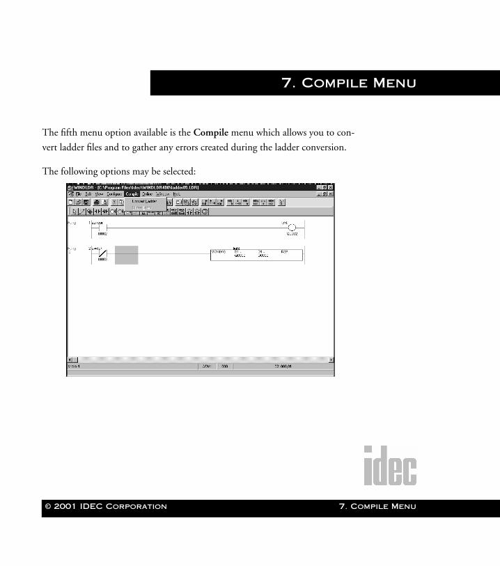
© 2001 IDEC Corporation
WLDR ReferenceBook Page 1 Thursday, April 5, 2001 3:36 PM
7. Compile Menu
The fifth menu option available is the Compile menu which allows you to con-
vert ladder files and to gather any errors created during the ladder conversion.
The following options may be selected:
7. Compile Menu
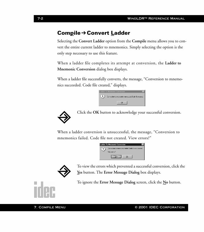
7-2 WindLDR™ Reference Manual
7. Compile
WLDR ReferenceBook Page 2 Thursday, April 5, 2001 3:36 PM
Compile➔Convert LadderSelecting the Convert Ladder option from the Compile menu allows you to con-
vert the entire current ladder to mnemonics. Simply selecting the option is the
only step necessary to use this feature.
When a ladder file completes its attempt at conversion, the Ladder to
Mnemonic Conversion dialog box displays.
When a ladder file successfully converts, the message, “Conversion to mnemo-
nics succeeded. Code file created,” displays.
When a ladder conversion is unsuccessful, the message, “Conversion to
mnemonics failed. Code file not created. View errors?”
Click the OK button to acknowledge your successful conversion.
To view the errors which prevented a successful conversion, click the
Yes button. The Error Message Dialog box displays.
To ignore the Error Message Dialog screen, click the No button.
Menu © 2001 IDEC Corporation
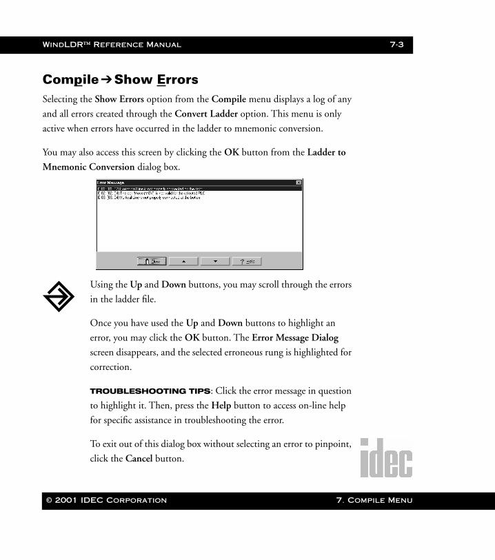
WindLDR™ Reference Manual 7-3
WLDR ReferenceBook Page 3 Thursday, April 5, 2001 3:36 PM
Compile➔Show ErrorsSelecting the Show Errors option from the Compile menu displays a log of any
and all errors created through the Convert Ladder option. This menu is only
active when errors have occurred in the ladder to mnemonic conversion.
You may also access this screen by clicking the OK button from the Ladder to
Mnemonic Conversion dialog box.
Using the Up and Down buttons, you may scroll through the errors
in the ladder file.
Once you have used the Up and Down buttons to highlight an
error, you may click the OK button. The Error Message Dialog
screen disappears, and the selected erroneous rung is highlighted for
correction.
TROUBLESHOOTING TIPS: Click the error message in question
to highlight it. Then, press the Help button to access on-line help
for specific assistance in troubleshooting the error.
To exit out of this dialog box without selecting an error to pinpoint,
click the Cancel button.
© 2001 IDEC Corporation 7. Compile Menu

7-4 WindLDR™ Reference Manual
7. Compile
WLDR ReferenceBook Page 4 Thursday, April 5, 2001 3:36 PM
NOTE: You also may edit the ladder without closing the Error Message Dialog screen.
However, adding or deleting rungs this way will alter the locations of the fol-
lowing error messages.
Menu © 2001 IDEC Corporation
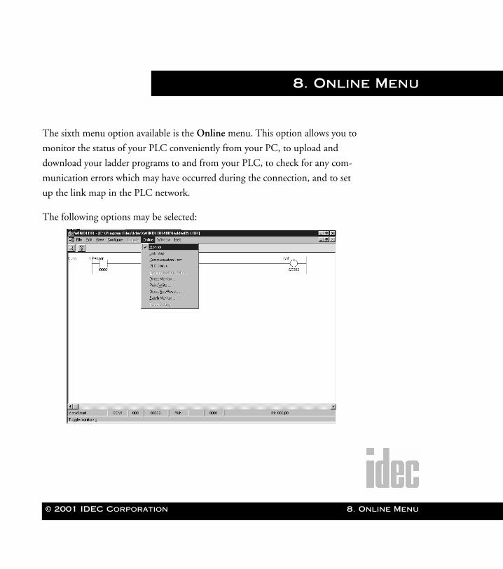
© 2001 IDEC Corporation
WLDR ReferenceBook Page 1 Thursday, April 5, 2001 3:36 PM
8. Online Menu
The sixth menu option available is the Online menu. This option allows you to
monitor the status of your PLC conveniently from your PC, to upload and
download your ladder programs to and from your PLC, to check for any com-
munication errors which may have occurred during the connection, and to set
up the link map in the PLC network.
The following options may be selected:
8. Online Menu
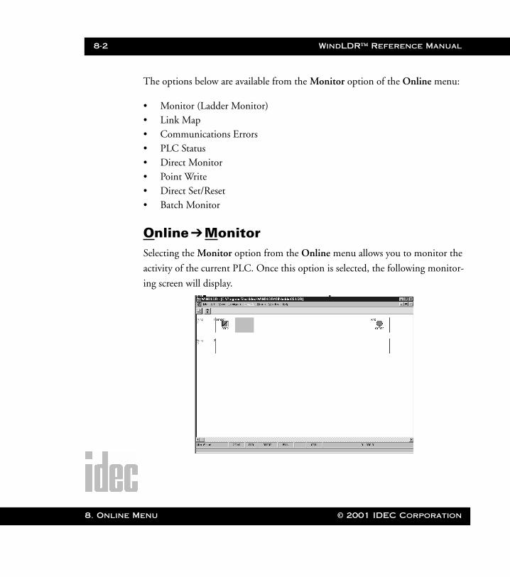
8-2 WindLDR™ Reference Manual
8. Online M
WLDR ReferenceBook Page 2 Thursday, April 5, 2001 3:36 PM
The options below are available from the Monitor option of the Online menu:
• Monitor (Ladder Monitor)• Link Map• Communications Errors• PLC Status• Direct Monitor• Point Write• Direct Set/Reset• Batch Monitor
Online➔MonitorSelecting the Monitor option from the Online menu allows you to monitor the
activity of the current PLC. Once this option is selected, the following monitor-
ing screen will display.
enu © 2001 IDEC Corporation
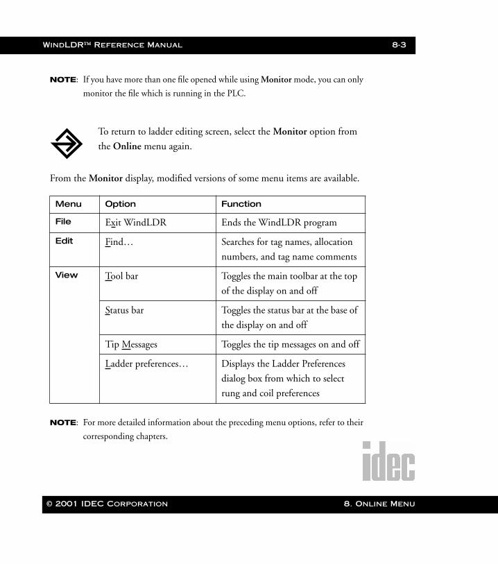
WindLDR™ Reference Manual 8-3
WLDR ReferenceBook Page 3 Thursday, April 5, 2001 3:36 PM
NOTE: If you have more than one file opened while using Monitor mode, you can only
monitor the file which is running in the PLC.
From the Monitor display, modified versions of some menu items are available.
NOTE: For more detailed information about the preceding menu options, refer to their
corresponding chapters.
Menu Option Function
File Exit WindLDR Ends the WindLDR program
Edit Find… Searches for tag names, allocation
numbers, and tag name comments
View Tool bar Toggles the main toolbar at the top
of the display on and off
Status bar Toggles the status bar at the base of
the display on and off
Tip Messages Toggles the tip messages on and off
Ladder preferences… Displays the Ladder Preferences
dialog box from which to select
rung and coil preferences
To return to ladder editing screen, select the Monitor option from
the Online menu again.
© 2001 IDEC Corporation 8. Online Menu
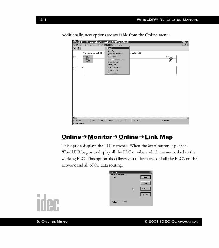
8-4 WindLDR™ Reference Manual
8. Online M
WLDR ReferenceBook Page 4 Thursday, April 5, 2001 3:36 PM
Additionally, new options are available from the Online menu.
Online➔Monitor ➔Online➔Link MapThis option displays the PLC network. When the Start button is pushed,
WindLDR begins to display all the PLC numbers which are networked to the
working PLC. This option also allows you to keep track of all the PLC’s on the
network and all of the data routing.
enu © 2001 IDEC Corporation
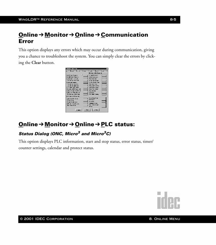
WindLDR™ Reference Manual 8-5
WLDR ReferenceBook Page 5 Thursday, April 5, 2001 3:36 PM
Online➔Monitor ➔Online➔Communication ErrorThis option displays any errors which may occur during communication, giving
you a chance to troubleshoot the system. You can simply clear the errors by click-
ing the Clear button.
Online➔Monitor ➔Online➔PLC status:
Status Dialog (ONC, Micro3 and Micro3C)
This option displays PLC information, start and stop status, error status, timer/
counter settings, calendar and protect status.
© 2001 IDEC Corporation 8. Online Menu
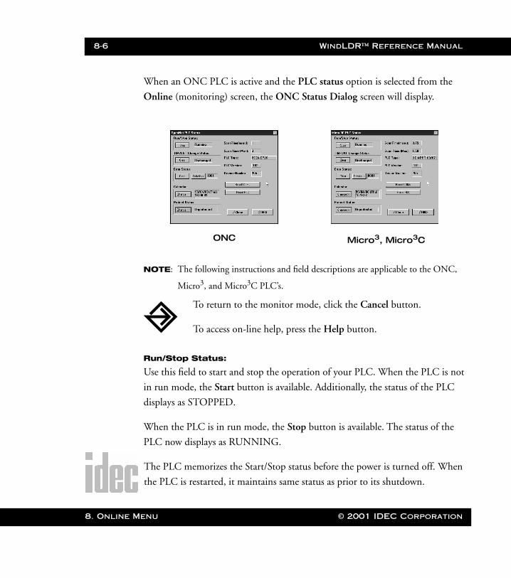
8-6 WindLDR™ Reference Manual
8. Online M
WLDR ReferenceBook Page 6 Thursday, April 5, 2001 3:36 PM
When an ONC PLC is active and the PLC status option is selected from the
Online (monitoring) screen, the ONC Status Dialog screen will display.
NOTE: The following instructions and field descriptions are applicable to the ONC,
Micro3, and Micro3C PLC’s.
Run/Stop Status:
Use this field to start and stop the operation of your PLC. When the PLC is not
in run mode, the Start button is available. Additionally, the status of the PLC
displays as STOPPED.
When the PLC is in run mode, the Stop button is available. The status of the
PLC now displays as RUNNING.
The PLC memorizes the Start/Stop status before the power is turned off. When
the PLC is restarted, it maintains same status as prior to its shutdown.
ONC Micro3, Micro3C
To return to the monitor mode, click the Cancel button.
To access on-line help, press the Help button.
enu © 2001 IDEC Corporation
WindLDR™ Reference Manual 8-7
WLDR ReferenceBook Page 7 Thursday, April 5, 2001 3:36 PM
Tim/Cnt Change Status:
When the status displays as CHANGED, you may press the Clear button. This
function serves two purposes:
• To clear the modified counter and counter preset values • To restore the original timer and counter preset values
Once the Clear button has been pressed, the status again displays as
UNCHANGED.
Error Status:
Use this option to view all errors which have occurred during operations. The
number of the error displays in the accompanying field.
Clear
Click the Clear button to erase errors after they have been fixed. If an
error has not been fixed, it will not clear.
© 2001 IDEC Corporation 8. Online Menu
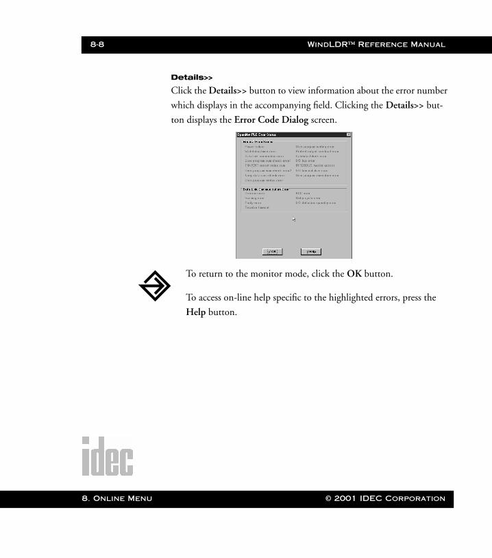
8-8 WindLDR™ Reference Manual
8. Online M
WLDR ReferenceBook Page 8 Thursday, April 5, 2001 3:36 PM
Details>>
Click the Details>> button to view information about the error number
which displays in the accompanying field. Clicking the Details>> but-
ton displays the Error Code Dialog screen.
To return to the monitor mode, click the OK button.
To access on-line help specific to the highlighted errors, press the
Help button.
enu © 2001 IDEC Corporation

WindLDR™ Reference Manual 8-9
WLDR ReferenceBook Page 9 Thursday, April 5, 2001 3:36 PM
The following table displays a list of the most common error numbers and
descriptions.
Error Number Error Description
1 Power failure
2 WDT (watchdog timer error)
3 CRC comparison code keep error
4 User program CRC error
5 Timer/counter preset value CRC error
6 Program sum check error
7 Keep data sum check error
8 User program syntax error
9 System program error
10 User program writing error
© 2001 IDEC Corporation 8. Online Menu
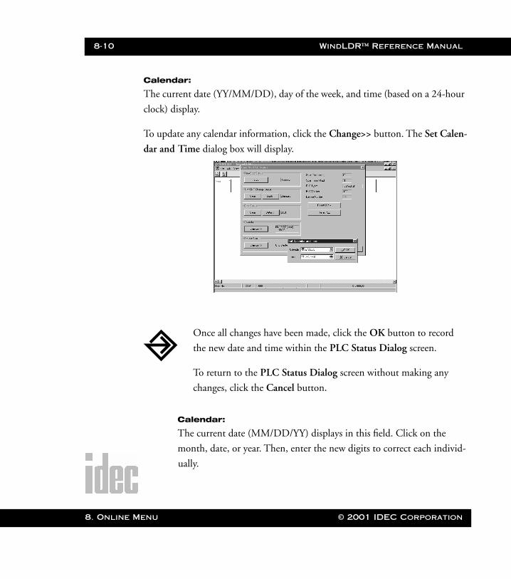
8-10 WindLDR™ Reference Manual
8. Online M
WLDR ReferenceBook Page 10 Thursday, April 5, 2001 3:36 PM
Calendar:
The current date (YY/MM/DD), day of the week, and time (based on a 24-hour
clock) display.
To update any calendar information, click the Change>> button. The Set Calen-
dar and Time dialog box will display.
Calendar:
The current date (MM/DD/YY) displays in this field. Click on the
month, date, or year. Then, enter the new digits to correct each individ-
ually.
Once all changes have been made, click the OK button to record
the new date and time within the PLC Status Dialog screen.
To return to the PLC Status Dialog screen without making any
changes, click the Cancel button.
enu © 2001 IDEC Corporation
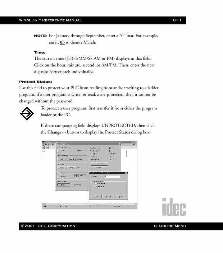
WindLDR™ Reference Manual 8-11
WLDR ReferenceBook Page 11 Thursday, April 5, 2001 3:36 PM
NOTE: For January through September, enter a “0” first. For example,
enter: 03 to denote March.
Time:
The current time ((H)H/MM/SS AM or PM) displays in this field.
Click on the hour, minute, second, or AM/PM. Then, enter the new
digits to correct each individually.
Protect Status:
Use this field to protect your PLC from reading from and/or writing to a ladder
program. If a user program is write- or read/write-protected, then it cannot be
changed without the password.
To protect a user program, first transfer it from either the program
loader or the PC.
If the accompanying field displays UNPROTECTED, then click
the Change>> button to display the Protect Status dialog box.
© 2001 IDEC Corporation 8. Online Menu

8-12 WindLDR™ Reference Manual
8. Online M
WLDR ReferenceBook Page 12 Thursday, April 5, 2001 3:36 PM
IMPORTANT:
Password:
Enter a password of one to four digits using the 0 – 9 and A – F keys.
Make sure to note this password. Future changes in protect status can-
not be made without it.
Protect type:
Select one of the following two protection modes: Disable Protect or
Enable Protect.
Scan Time:
This field displays the current amount of times it takes to complete one loop of
the program in milliseconds. The scan time is updated every scan.
Scan Time (Max):
This field displays a record of the longest amount of time (since the PLC started)
it has taken to complete one loop of the program in milliseconds. The maximum
scan time is updated every scan.
Complete the following fields. Then, click the Enable button to
establish protection. Once you return to the PLC Status Dialog
screen, the Protect Status: field will display PROTECTED.
To back out of this option without setting up protection status,
click the Disable button.
To access on-line help, press the Help button.
enu © 2001 IDEC Corporation
WindLDR™ Reference Manual 8-13
WLDR ReferenceBook Page 13 Thursday, April 5, 2001 3:36 PM
[PLC] Status Dialog Box, continued
PLC Type:
This field displays the configuration of the attached PLC base unit.
PLC Version:
This field displays the version number of the attached PLC unit.
Device Number:
This field displays the device number assigned to the PLC which is currently
communicating with the program.
Reset COMx
Press this button to re-initializes the communications port.
Emergency
When all else fails, click the Reset PLC button in the Emergency field to reset
the current PLC.
© 2001 IDEC Corporation 8. Online Menu
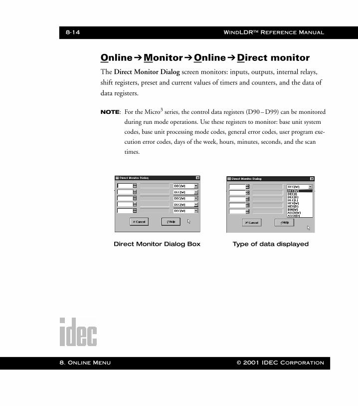
8-14 WindLDR™ Reference Manual
8. Online M
WLDR ReferenceBook Page 14 Thursday, April 5, 2001 3:36 PM
Online➔Monitor ➔Online➔Direct monitor The Direct Monitor Dialog screen monitors: inputs, outputs, internal relays,
shift registers, preset and current values of timers and counters, and the data of
data registers.
NOTE: For the Micro3 series, the control data registers (D90 – D99) can be monitored
during run mode operations. Use these registers to monitor: base unit system
codes, base unit processing mode codes, general error codes, user program exe-
cution error codes, days of the week, hours, minutes, seconds, and the scan
times.
Direct Monitor Dialog Box Type of data displayed
enu © 2001 IDEC Corporation
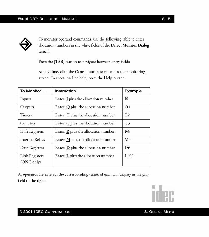
WindLDR™ Reference Manual 8-15
WLDR ReferenceBook Page 15 Thursday, April 5, 2001 3:36 PM
As operands are entered, the corresponding values of each will display in the gray
field to the right.
To Monitor… Instruction Example
Inputs Enter: I plus the allocation number I0
Outputs Enter: Q plus the allocation number Q1
Timers Enter: T plus the allocation number T2
Counters Enter: C plus the allocation number C3
Shift Registers Enter: R plus the allocation number R4
Internal Relays Enter: M plus the allocation number M5
Data Registers Enter: D plus the allocation number D6
Link Registers
(ONC only)
Enter: L plus the allocation number L100
To monitor operand commands, use the following table to enter
allocation numbers in the white fields of the Direct Monitor Dialog
screen.
Press the [TAB] button to navigate between entry fields.
At any time, click the Cancel button to return to the monitoring
screen. To access on-line help, press the Help button.
© 2001 IDEC Corporation 8. Online Menu

8-16 WindLDR™ Reference Manual
8. Online M
WLDR ReferenceBook Page 16 Thursday, April 5, 2001 3:36 PM
The method of entering operands follows the syntax of the PLC communica-
tions protocols.
Input Number Syntax
i0 Monitor input 0 (one bit)
I0 Monitor inputs 0 – 7 (one byte)
q0 Monitor output 0 (one bit)
Q0 Monitor outputs 0 – 7 (one byte)
m0 Monitor internal relay 0 (one bit)
M0 Monitor internal relays 0 – 7 (one byte)
t0 Timer 0 current value (one word)
T0 Timer 0 preset value (one word)
c0 Counter 0 current value (one word)
C0 Counter 0 preset value (one word)
D0 Read data register 0 (one word)
enu © 2001 IDEC Corporation
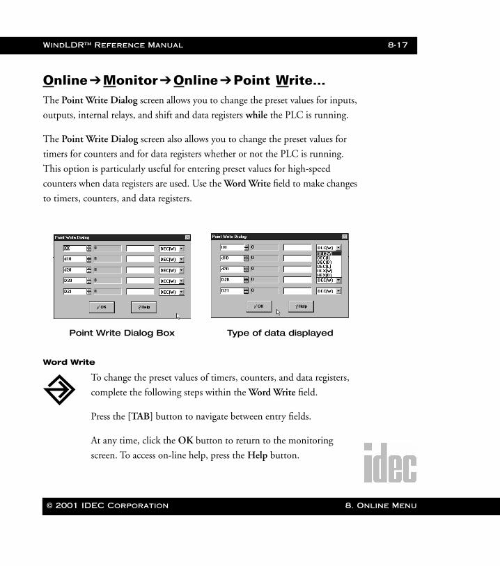
WindLDR™ Reference Manual 8-17
WLDR ReferenceBook Page 17 Thursday, April 5, 2001 3:36 PM
Online➔Monitor ➔Online➔Point Write… The Point Write Dialog screen allows you to change the preset values for inputs,
outputs, internal relays, and shift and data registers while the PLC is running.
The Point Write Dialog screen also allows you to change the preset values for
timers for counters and for data registers whether or not the PLC is running.
This option is particularly useful for entering preset values for high-speed
counters when data registers are used. Use the Word Write field to make changes
to timers, counters, and data registers.
Word Write
Point Write Dialog Box Type of data displayed
To change the preset values of timers, counters, and data registers,
complete the following steps within the Word Write field.
Press the [TAB] button to navigate between entry fields.
At any time, click the OK button to return to the monitoring
screen. To access on-line help, press the Help button.
© 2001 IDEC Corporation 8. Online Menu
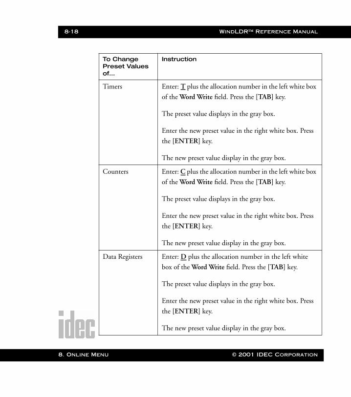
8-18 WindLDR™ Reference Manual
8. Online M
WLDR ReferenceBook Page 18 Thursday, April 5, 2001 3:36 PM
To Change Preset Values of…
Instruction
Timers Enter: T plus the allocation number in the left white box
of the Word Write field. Press the [TAB] key.
The preset value displays in the gray box.
Enter the new preset value in the right white box. Press
the [ENTER] key.
The new preset value display in the gray box.
Counters Enter: C plus the allocation number in the left white box
of the Word Write field. Press the [TAB] key.
The preset value displays in the gray box.
Enter the new preset value in the right white box. Press
the [ENTER] key.
The new preset value display in the gray box.
Data Registers Enter: D plus the allocation number in the left white
box of the Word Write field. Press the [TAB] key.
The preset value displays in the gray box.
Enter the new preset value in the right white box. Press
the [ENTER] key.
The new preset value display in the gray box.
enu © 2001 IDEC Corporation
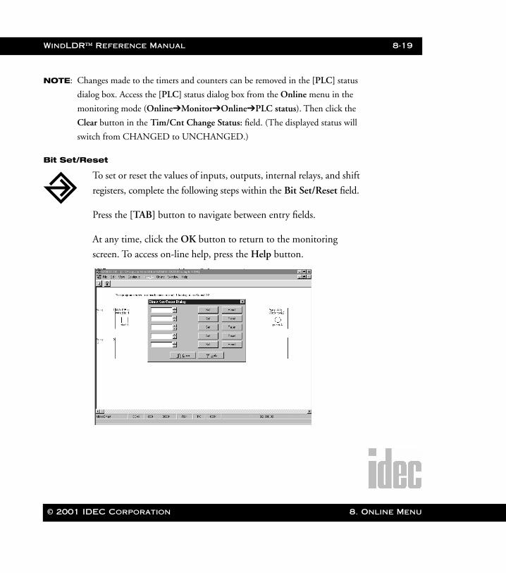
WindLDR™ Reference Manual 8-19
WLDR ReferenceBook Page 19 Thursday, April 5, 2001 3:36 PM
NOTE: Changes made to the timers and counters can be removed in the [PLC] status
dialog box. Access the [PLC] status dialog box from the Online menu in the
monitoring mode (Online➔Monitor➔Online➔PLC status). Then click the
Clear button in the Tim/Cnt Change Status: field. (The displayed status will
switch from CHANGED to UNCHANGED.)
Bit Set/Reset
To set or reset the values of inputs, outputs, internal relays, and shift
registers, complete the following steps within the Bit Set/Reset field.
Press the [TAB] button to navigate between entry fields.
At any time, click the OK button to return to the monitoring
screen. To access on-line help, press the Help button.
© 2001 IDEC Corporation 8. Online Menu

8-20 WindLDR™ Reference Manual
8. Online M
WLDR ReferenceBook Page 20 Thursday, April 5, 2001 3:36 PM
NOTE: These operands can only be changed while the PLC is in run mode. Addition-
ally, the input status will be maintained for the length of one scan only. The sta-
tus continually updates with the newly read scan information.
NOTE: You may also right-click with your mouse to set/reset a selected Internal Relay
or Output Coil as long as the selection does not conflict with the program
logic.
Online➔Monitor ➔Online➔Batch MonitorThis option allows you to monitor an array of inputs, outputs, timers, counters,
data registers, and so forth by simply selecting the operand.
To Set or Reset the Values of…
Instruction
Inputs, Outputs,
Internal Relays,
Shift Registers
Enter the desired allocation number into the white box
of the Bit Set/Reset field. Press the [TAB] key.
If the operand is OFF, 0 will display in the gray box.
If the operand is ON, 1 will display in the gray box.
To set this operand, click the Set button.
To reset this operand, click the Reset button.
enu © 2001 IDEC Corporation
WindLDR™ Reference Manual 8-21
WLDR ReferenceBook Page 21 Thursday, April 5, 2001 3:36 PM
Online➔Upload program…Selecting the Upload program… option from the Online menu allows you to
upload a file from your PLC and convert it to a ladder file on your PC.
You may also click the toolbar button:
To monitor your programs in batches:
1. Click Online➔ Monitor from the Menu Commands toolbar.
2. Click Online➔ Batch Monitor from the Menu Commands tool-
bar.
3. Type the desired operand and starting address.
4. Scroll forward and backward by clicking the or buttons.
© 2001 IDEC Corporation 8. Online Menu
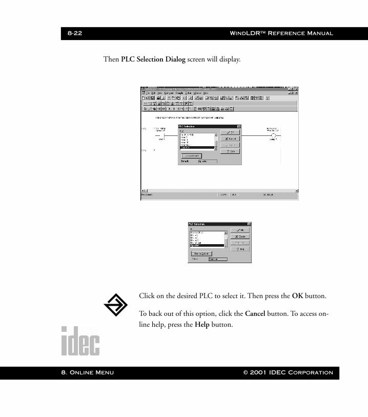
8-22 WindLDR™ Reference Manual
8. Online M
WLDR ReferenceBook Page 22 Thursday, April 5, 2001 3:36 PM
Then PLC Selection Dialog screen will display.
Click on the desired PLC to select it. Then press the OK button.
To back out of this option, click the Cancel button. To access on-
line help, press the Help button.
enu © 2001 IDEC Corporation
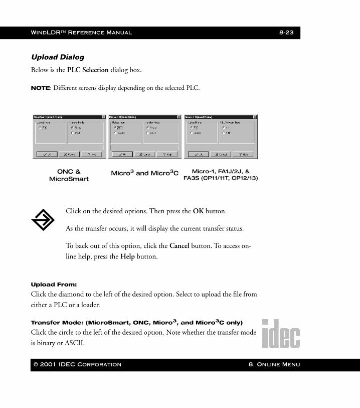
WindLDR™ Reference Manual 8-23
WLDR ReferenceBook Page 23 Thursday, April 5, 2001 3:36 PM
Upload Dialog
Below is the PLC Selection dialog box.
NOTE: Different screens display depending on the selected PLC.
Upload From:
Click the diamond to the left of the desired option. Select to upload the file from
either a PLC or a loader.
Transfer Mode: (MicroSmart, ONC, Micro3, and Micro3C only)
Click the circle to the left of the desired option. Note whether the transfer mode
is binary or ASCII.
ONC &MicroSmart
Micro3 and Micro3C Micro-1, FA1J/2J, & FA3S (CP11/11T, CP12/13)
Click on the desired options. Then press the OK button.
As the transfer occurs, it will display the current transfer status.
To back out of this option, click the Cancel button. To access on-
line help, press the Help button.
© 2001 IDEC Corporation 8. Online Menu
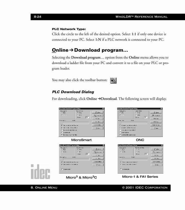
8-24 WindLDR™ Reference Manual
8. Online M
WLDR ReferenceBook Page 24 Thursday, April 5, 2001 3:36 PM
PLC Network Type:
Click the circle to the left of the desired option. Select 1:1 if only one device is
connected to your PC. Select 1:N if a PLC network is connected to your PC.
Online➔Download program…Selecting the Download program… option from the Online menu allows you to
download a ladder file from your PC and convert it to a file on your PLC or pro-
gram loader.
You may also click the toolbar button:
PLC Download Dialog
For downloading, click Online ➔Download. The following screen will display.
MicroSmart ONC
Micro3 & Micro3C Micro-1 & FA1 Series
enu © 2001 IDEC Corporation
WindLDR™ Reference Manual 8-25
WLDR ReferenceBook Page 25 Thursday, April 5, 2001 3:36 PM
Download To:
Click the diamond to the left of the desired option. Select to download the file to
either a PLC or a loader.
PLC Network Type: (Micro-1, FA1J, FA2J, and FA3S series)
Click the diamond to the left of the desired option. Select 1:1 if only one device
is connected to your PC. Select 1:N if more than one device is connected to your
PC.
Transfer Mode:
Click the diamond to the left of the desired option. Note whether the transfer
mode is binary or ASCII.
Click on the desired options. Then press the OK button.
As the transfer occurs, it will display the current transfer status.
To back out of this option, click the Cancel button. To access on-
line help, press the Help button.
© 2001 IDEC Corporation 8. Online Menu

8-26 WindLDR™ Reference Manual
8. Online M
WLDR ReferenceBook Page 26 Thursday, April 5, 2001 3:36 PM
enu © 2001 IDEC Corporation
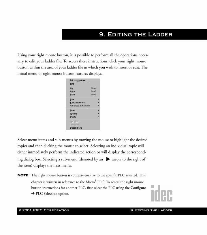
© 2001 IDEC Corporation
WLDR ReferenceBook Page 1 Thursday, April 5, 2001 3:36 PM
9. Editing the Ladder
Using your right mouse button, it is possible to perform all the operations neces-
sary to edit your ladder file. To access these instructions, click your right mouse
button within the area of your ladder file in which you wish to insert or edit. The
initial menu of right mouse button features displays.
Select menu items and sub-menus by moving the mouse to highlight the desired
topics and then clicking the mouse to select. Selecting an individual topic will
either immediately perform the indicated action or will display the correspond-
ing dialog box. Selecting a sub-menu (denoted by an arrow to the right of
the item) displays the next menu.
NOTE: The right mouse button is context-sensitive to the specific PLC selected. This
chapter is written in reference to the Micro3 PLC. To access the right mouse
button instructions for another PLC, first select the PLC using the Configure
➔ PLC Selection option.
9. Editing the Ladder
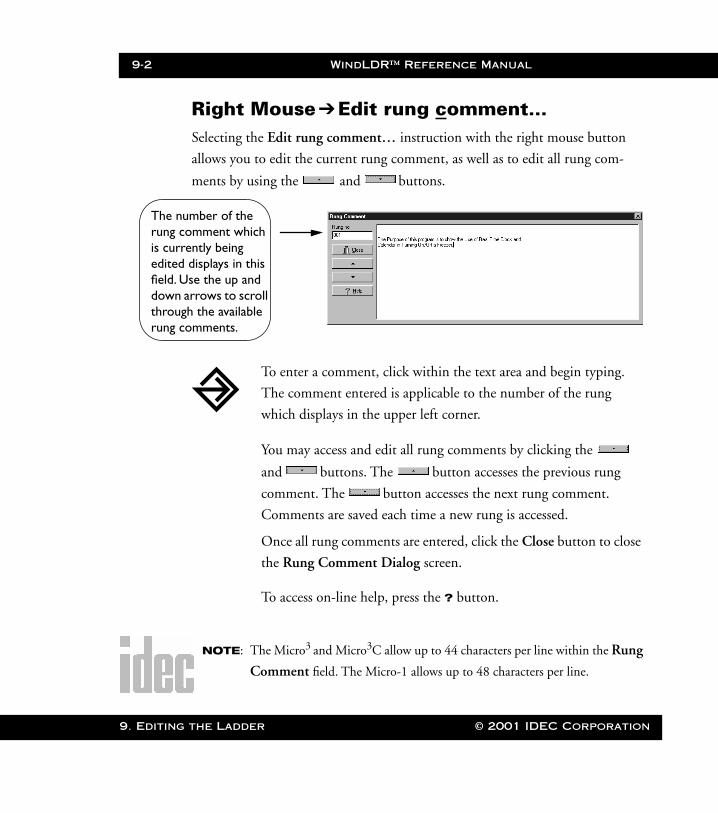
9-2 WindLDR™ Reference Manual
9. Editing
The nrung cis cureditedfield. Udownthrourung c
WLDR ReferenceBook Page 2 Thursday, April 5, 2001 3:36 PM
Right Mouse ➔Edit rung comment…Selecting the Edit rung comment… instruction with the right mouse button
allows you to edit the current rung comment, as well as to edit all rung com-
ments by using the and buttons.
NOTE: The Micro3 and Micro3C allow up to 44 characters per line within the Rung
Comment field. The Micro-1 allows up to 48 characters per line.
To enter a comment, click within the text area and begin typing.
The comment entered is applicable to the number of the rung
which displays in the upper left corner.
You may access and edit all rung comments by clicking the
and buttons. The button accesses the previous rung
comment. The button accesses the next rung comment.
Comments are saved each time a new rung is accessed.
Once all rung comments are entered, click the Close button to close
the Rung Comment Dialog screen.
To access on-line help, press the ? button.
umber of the omment which
rently being displays in this se the up and
arrows to scroll gh the available omments.
the Ladder © 2001 IDEC Corporation
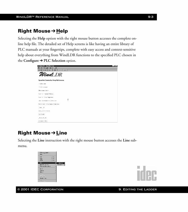
WindLDR™ Reference Manual 9-3
WLDR ReferenceBook Page 3 Thursday, April 5, 2001 3:36 PM
Right Mouse ➔HelpSelecting the Help option with the right mouse button accesses the complete on-
line help file. The detailed set of Help screens is like having an entire library of
PLC manuals at your fingertips, complete with easy access and context-sensitive
help about everything from WindLDR functions to the specified PLC chosen in
the Configure ➔ PLC Selection option.
Right Mouse ➔LineSelecting the Line instruction with the right mouse button accesses the Line sub-
menu.
© 2001 IDEC Corporation 9. Editing the Ladder
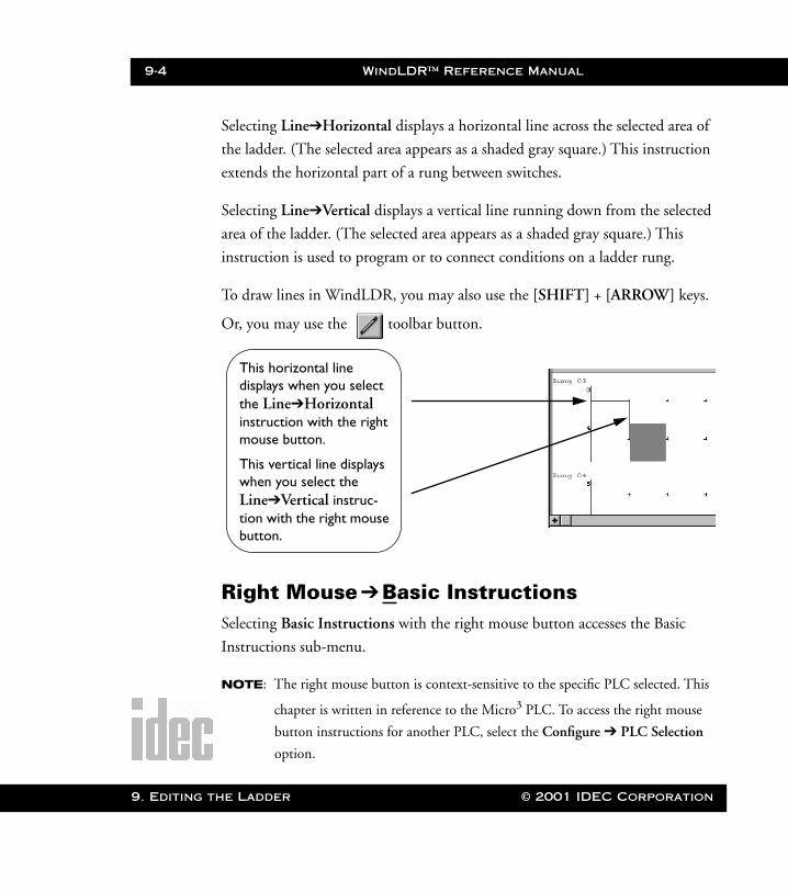
9-4 WindLDR™ Reference Manual
9. Editing t
WLDR ReferenceBook Page 4 Thursday, April 5, 2001 3:36 PM
Selecting Line➔Horizontal displays a horizontal line across the selected area of
the ladder. (The selected area appears as a shaded gray square.) This instruction
extends the horizontal part of a rung between switches.
Selecting Line➔Vertical displays a vertical line running down from the selected
area of the ladder. (The selected area appears as a shaded gray square.) This
instruction is used to program or to connect conditions on a ladder rung.
To draw lines in WindLDR, you may also use the [SHIFT] + [ARROW] keys.
Or, you may use the toolbar button.
Right Mouse ➔Basic InstructionsSelecting Basic Instructions with the right mouse button accesses the Basic
Instructions sub-menu.
NOTE: The right mouse button is context-sensitive to the specific PLC selected. This
chapter is written in reference to the Micro3 PLC. To access the right mouse
button instructions for another PLC, select the Configure ➔ PLC Selection
option.
This horizontal line displays when you select the Line➔Horizontal instruction with the right mouse button.
This vertical line displays when you select the Line➔Vertical instruc-tion with the right mouse button.
he Ladder © 2001 IDEC Corporation
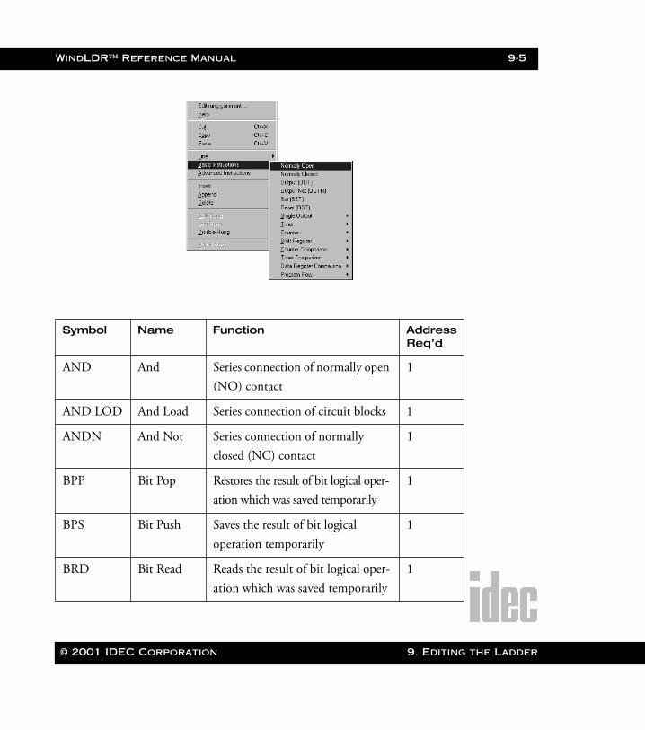
WindLDR™ Reference Manual 9-5
WLDR ReferenceBook Page 5 Thursday, April 5, 2001 3:36 PM
Symbol Name Function AddressReq’d
AND And Series connection of normally open
(NO) contact
1
AND LOD And Load Series connection of circuit blocks 1
ANDN And Not Series connection of normally
closed (NC) contact
1
BPP Bit Pop Restores the result of bit logical oper-
ation which was saved temporarily
1
BPS Bit Push Saves the result of bit logical
operation temporarily
1
BRD Bit Read Reads the result of bit logical oper-
ation which was saved temporarily
1
© 2001 IDEC Corporation 9. Editing the Ladder
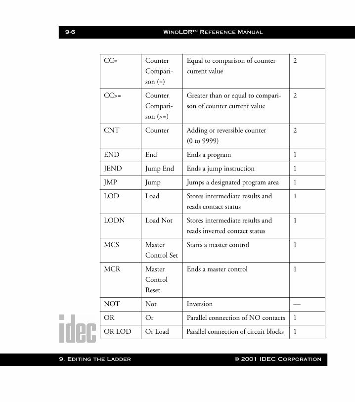
9-6 WindLDR™ Reference Manual
9. Editing t
WLDR ReferenceBook Page 6 Thursday, April 5, 2001 3:36 PM
CC= Counter
Compari-
son (=)
Equal to comparison of counter
current value
2
CC>= Counter
Compari-
son (>=)
Greater than or equal to compari-
son of counter current value
2
CNT Counter Adding or reversible counter
(0 to 9999)
2
END End Ends a program 1
JEND Jump End Ends a jump instruction 1
JMP Jump Jumps a designated program area 1
LOD Load Stores intermediate results and
reads contact status
1
LODN Load Not Stores intermediate results and
reads inverted contact status
1
MCS Master
Control Set
Starts a master control 1
MCR Master
Control
Reset
Ends a master control 1
NOT Not Inversion —
OR Or Parallel connection of NO contacts 1
OR LOD Or Load Parallel connection of circuit blocks 1
he Ladder © 2001 IDEC Corporation
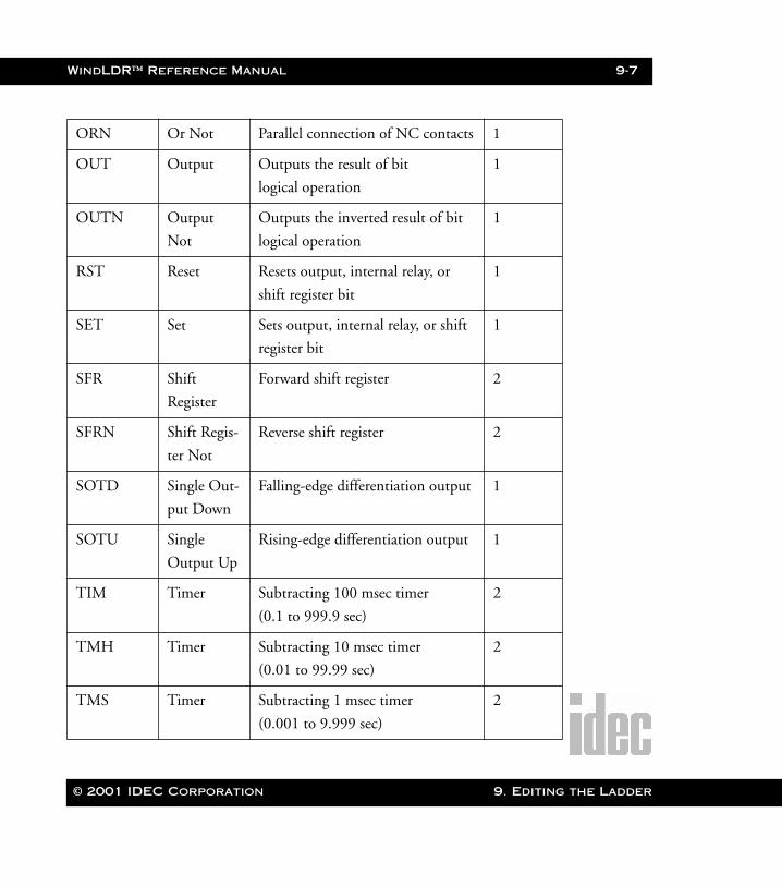
WindLDR™ Reference Manual 9-7
WLDR ReferenceBook Page 7 Thursday, April 5, 2001 3:36 PM
ORN Or Not Parallel connection of NC contacts 1
OUT Output Outputs the result of bit
logical operation
1
OUTN Output
Not
Outputs the inverted result of bit
logical operation
1
RST Reset Resets output, internal relay, or
shift register bit
1
SET Set Sets output, internal relay, or shift
register bit
1
SFR Shift
Register
Forward shift register 2
SFRN Shift Regis-
ter Not
Reverse shift register 2
SOTD Single Out-
put Down
Falling-edge differentiation output 1
SOTU Single
Output Up
Rising-edge differentiation output 1
TIM Timer Subtracting 100 msec timer
(0.1 to 999.9 sec)
2
TMH Timer Subtracting 10 msec timer
(0.01 to 99.99 sec)
2
TMS Timer Subtracting 1 msec timer
(0.001 to 9.999 sec)
2
© 2001 IDEC Corporation 9. Editing the Ladder
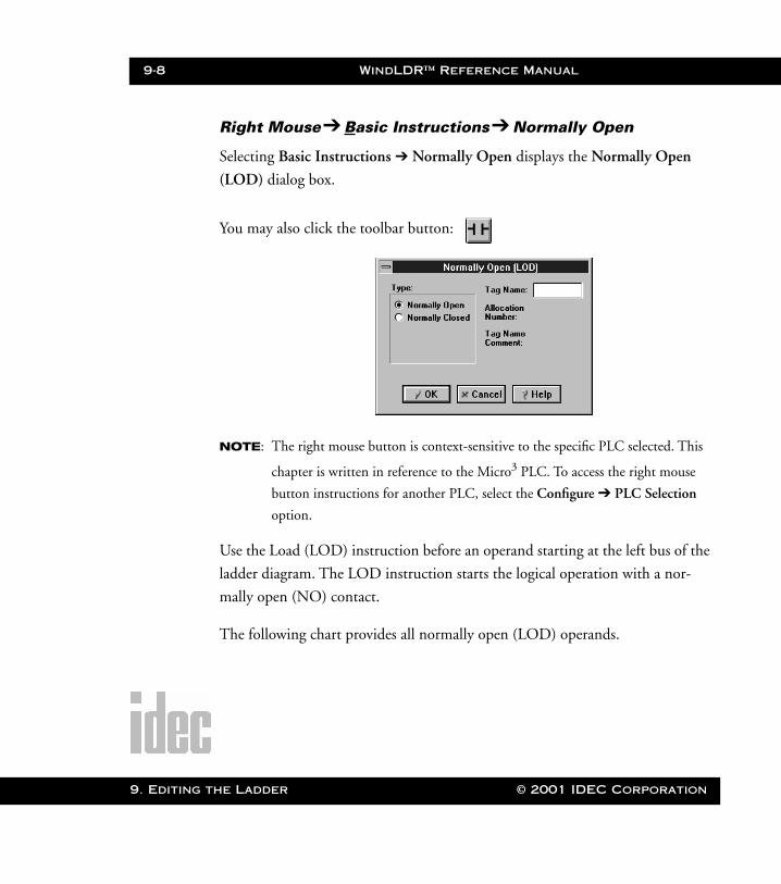
9-8 WindLDR™ Reference Manual
9. Editing t
WLDR ReferenceBook Page 8 Thursday, April 5, 2001 3:36 PM
Right Mouse➔ Basic Instructions➔ Normally Open
Selecting Basic Instructions ➔ Normally Open displays the Normally Open
(LOD) dialog box.
You may also click the toolbar button:
NOTE: The right mouse button is context-sensitive to the specific PLC selected. This
chapter is written in reference to the Micro3 PLC. To access the right mouse
button instructions for another PLC, select the Configure ➔ PLC Selection
option.
Use the Load (LOD) instruction before an operand starting at the left bus of the
ladder diagram. The LOD instruction starts the logical operation with a nor-
mally open (NO) contact.
The following chart provides all normally open (LOD) operands.
he Ladder © 2001 IDEC Corporation
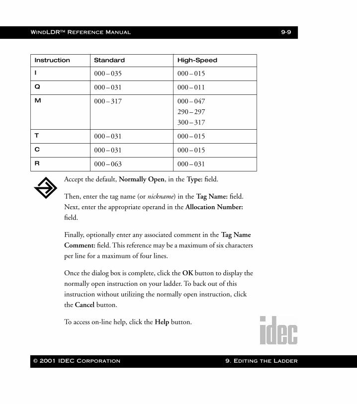
WindLDR™ Reference Manual 9-9
WLDR ReferenceBook Page 9 Thursday, April 5, 2001 3:36 PM
Instruction Standard High-Speed
I 000 – 035 000 – 015
Q 000 – 031 000 – 011
M 000 – 317 000 – 047
290 – 297
300 – 317
T 000 – 031 000 – 015
C 000 – 031 000 – 015
R 000 – 063 000 – 031
Accept the default, Normally Open, in the Type: field.
Then, enter the tag name (or nickname) in the Tag Name: field.
Next, enter the appropriate operand in the Allocation Number:
field.
Finally, optionally enter any associated comment in the Tag Name
Comment: field. This reference may be a maximum of six characters
per line for a maximum of four lines.
Once the dialog box is complete, click the OK button to display the
normally open instruction on your ladder. To back out of this
instruction without utilizing the normally open instruction, click
the Cancel button.
To access on-line help, click the Help button.
© 2001 IDEC Corporation 9. Editing the Ladder

9-10 WindLDR™ Reference Manual
9. Editing t
WLDR ReferenceBook Page 10 Thursday, April 5, 2001 3:36 PM
Right Mouse➔ Basic Instructions➔ Normally Closed
Selecting Basic Instructions➔Normally Closed displays the Normally Closed
(LODN) dialog box.
You may also click the toolbar button:
NOTE: The right mouse button is context-sensitive to the specific PLC selected. This
chapter is written in reference to the Micro3 PLC. To access the right mouse
button instructions for another PLC, select the Configure ➔ PLC Selection
option.
Use the Load Not (LODN) instruction before an operand starting at the left bus
of the ladder diagram. The LODN instruction starts the logical operation with a
normally closed (NC) contact.
The following chart provides all normally closed (LODN) operands.
he Ladder © 2001 IDEC Corporation

WindLDR™ Reference Manual 9-11
WLDR ReferenceBook Page 11 Thursday, April 5, 2001 3:36 PM
Instruction Standard High-Speed
I 000 – 035 000 – 015
Q 000 – 031 000 – 011
M 000 – 317 000 – 047
290 – 297
300 – 317
T 000 – 031 000 – 015
C 000 – 031 000 – 015
R 000 – 063 000 – 031
Accept the default, Normally Closed, in the Type: field. Then, enter
the tag name (or nickname) in the Tag Name: field.
Next, enter the appropriate operand in the Allocation Number:
field.
Finally, optionally enter any associated comment in the Tag Name
Comment: field. This reference may be a maximum of six characters
per line for a maximum of four lines.
Once the dialog box is complete, click the OK button to display the
normally closed instruction on your ladder.
To back out of this instruction without utilizing the normally closed
instruction, click the Cancel button.
To access on-line help, click the Help button.
© 2001 IDEC Corporation 9. Editing the Ladder
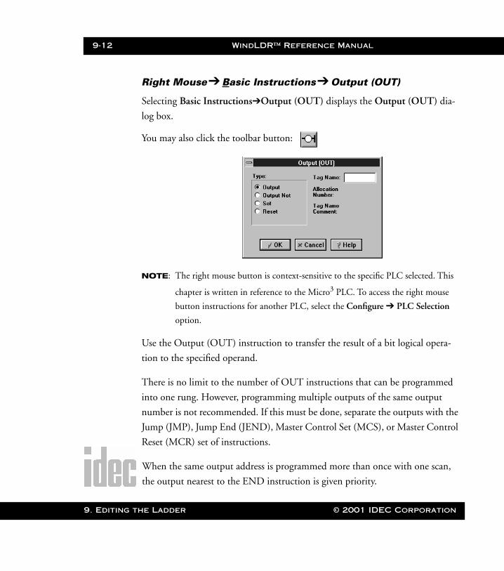
9-12 WindLDR™ Reference Manual
9. Editing t
WLDR ReferenceBook Page 12 Thursday, April 5, 2001 3:36 PM
Right Mouse➔ Basic Instructions➔ Output (OUT)
Selecting Basic Instructions➔Output (OUT) displays the Output (OUT) dia-
log box.
You may also click the toolbar button:
NOTE: The right mouse button is context-sensitive to the specific PLC selected. This
chapter is written in reference to the Micro3 PLC. To access the right mouse
button instructions for another PLC, select the Configure ➔ PLC Selection
option.
Use the Output (OUT) instruction to transfer the result of a bit logical opera-
tion to the specified operand.
There is no limit to the number of OUT instructions that can be programmed
into one rung. However, programming multiple outputs of the same output
number is not recommended. If this must be done, separate the outputs with the
Jump (JMP), Jump End (JEND), Master Control Set (MCS), or Master Control
Reset (MCR) set of instructions.
When the same output address is programmed more than once with one scan,
the output nearest to the END instruction is given priority.
he Ladder © 2001 IDEC Corporation

WindLDR™ Reference Manual 9-13
WLDR ReferenceBook Page 13 Thursday, April 5, 2001 3:36 PM
The following chart provides all OUT operands.
Instruction Standard High-Speed
I — —
Q 000 – 031 000 – 011
M 000 – 287 000 – 047
T — —
C — —
R — —
Accept the default, Output, in the Type: field. Then, enter the tag
name (or nickname) in the Tag Name: field.
Next, enter the appropriate operand in the Allocation Number:
field.
Finally, optionally enter any associated comment in the Tag Name
Comment: field. This reference may be a maximum of six characters
per line for a maximum of four lines.
Once the dialog box is complete, click the OK button to display the
OUT instruction on your ladder.
To back out of this instruction without inserting an output, click the
Cancel button.
To access on-line help, click the Help button.
© 2001 IDEC Corporation 9. Editing the Ladder

9-14 WindLDR™ Reference Manual
9. Editing t
WLDR ReferenceBook Page 14 Thursday, April 5, 2001 3:36 PM
Right Mouse➔ Basic Instructions➔ Output Not (OUTN)
Selecting Basic Instructions➔Output Not (OUTN) displays the Output Not
(OUTN) dialog box.
You may also click the toolbar button:
NOTE: The right mouse button is context-sensitive to the specific PLC selected. This
chapter is written in reference to the Micro3 PLC. To access the right mouse
button instructions for another PLC, select the Configure ➔ PLC Selection
option.
Use the Output Not (OUTN) instruction to transfer the inverted result of a bit
logical operation to the specified operand.
There is no limit to the number of OUTN instructions that can be programmed
into one rung. However, programming multiple outputs of the same output
number is not recommended. If this must be done, separate the outputs with the
Jump (JMP), Jump End (JEND), Master Control Set (MCS), or Master Control
Reset (MCR) set of instructions.
When the same output address is programmed more than once in one scan, the
output nearest to the END instruction is given priority.
he Ladder © 2001 IDEC Corporation
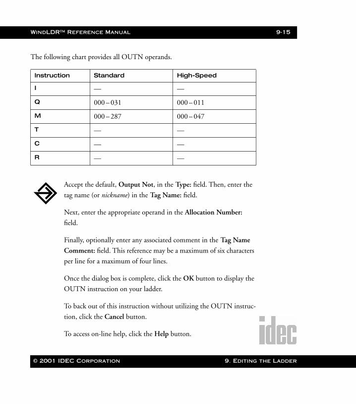
WindLDR™ Reference Manual 9-15
WLDR ReferenceBook Page 15 Thursday, April 5, 2001 3:36 PM
The following chart provides all OUTN operands.
Instruction Standard High-Speed
I — —
Q 000 – 031 000 – 011
M 000 – 287 000 – 047
T — —
C — —
R — —
Accept the default, Output Not, in the Type: field. Then, enter the
tag name (or nickname) in the Tag Name: field.
Next, enter the appropriate operand in the Allocation Number:
field.
Finally, optionally enter any associated comment in the Tag Name
Comment: field. This reference may be a maximum of six characters
per line for a maximum of four lines.
Once the dialog box is complete, click the OK button to display the
OUTN instruction on your ladder.
To back out of this instruction without utilizing the OUTN instruc-
tion, click the Cancel button.
To access on-line help, click the Help button.
© 2001 IDEC Corporation 9. Editing the Ladder
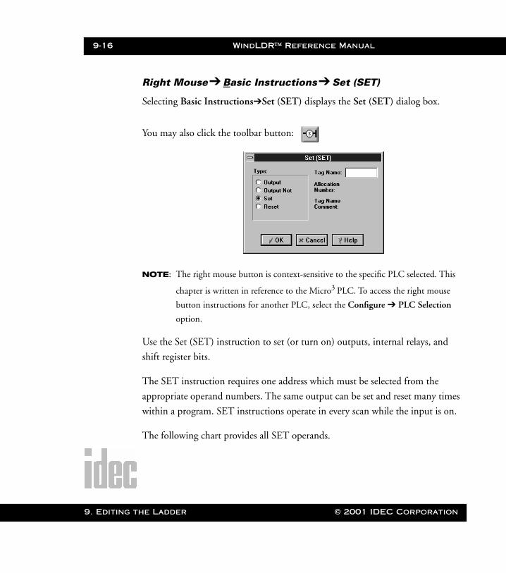
9-16 WindLDR™ Reference Manual
9. Editing t
WLDR ReferenceBook Page 16 Thursday, April 5, 2001 3:36 PM
Right Mouse➔ Basic Instructions➔ Set (SET)
Selecting Basic Instructions➔Set (SET) displays the Set (SET) dialog box.
You may also click the toolbar button:
NOTE: The right mouse button is context-sensitive to the specific PLC selected. This
chapter is written in reference to the Micro3 PLC. To access the right mouse
button instructions for another PLC, select the Configure ➔ PLC Selection
option.
Use the Set (SET) instruction to set (or turn on) outputs, internal relays, and
shift register bits.
The SET instruction requires one address which must be selected from the
appropriate operand numbers. The same output can be set and reset many times
within a program. SET instructions operate in every scan while the input is on.
The following chart provides all SET operands.
he Ladder © 2001 IDEC Corporation

WindLDR™ Reference Manual 9-17
WLDR ReferenceBook Page 17 Thursday, April 5, 2001 3:36 PM
Instruction Standard High-Speed
I — —
Q 000 – 031 000 – 011
M 000 – 287 000 – 047
T — —
C — —
R 000 – 063 000 – 031
Accept the default, Set, in the Type: field. Then, enter the tag name
(or nickname) in the Tag Name: field.
Next, enter the appropriate operand in the Allocation Number:
field.
Finally, optionally enter any associated comment in the Tag Name
Comment: field. This reference may be a maximum of six characters
per line for a maximum of four lines.
Once the dialog box is complete, click the OK button to display the
SET instruction on your ladder.
To back out of this instruction without utilizing the SET instruction,
click the Cancel button.
To access on-line help, click the Help button.
© 2001 IDEC Corporation 9. Editing the Ladder
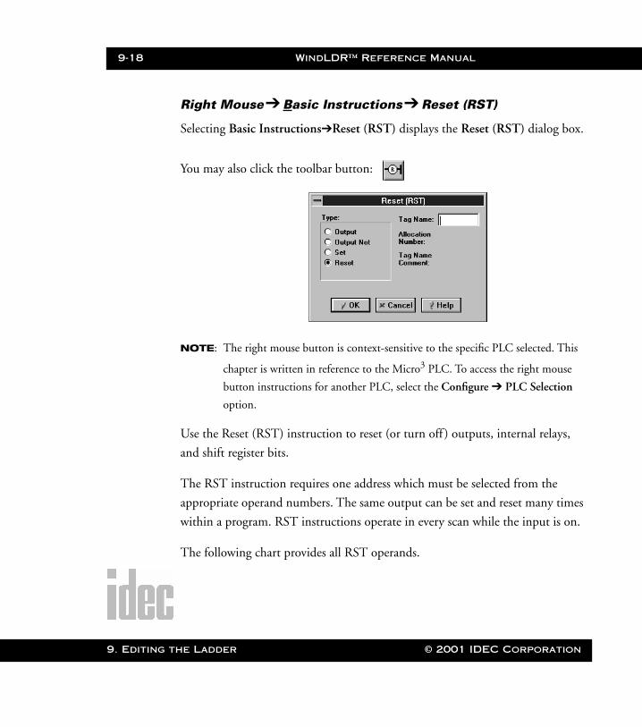
9-18 WindLDR™ Reference Manual
9. Editing t
WLDR ReferenceBook Page 18 Thursday, April 5, 2001 3:36 PM
Right Mouse➔ Basic Instructions➔ Reset (RST)
Selecting Basic Instructions➔Reset (RST) displays the Reset (RST) dialog box.
You may also click the toolbar button:
NOTE: The right mouse button is context-sensitive to the specific PLC selected. This
chapter is written in reference to the Micro3 PLC. To access the right mouse
button instructions for another PLC, select the Configure ➔ PLC Selection
option.
Use the Reset (RST) instruction to reset (or turn off ) outputs, internal relays,
and shift register bits.
The RST instruction requires one address which must be selected from the
appropriate operand numbers. The same output can be set and reset many times
within a program. RST instructions operate in every scan while the input is on.
The following chart provides all RST operands.
he Ladder © 2001 IDEC Corporation
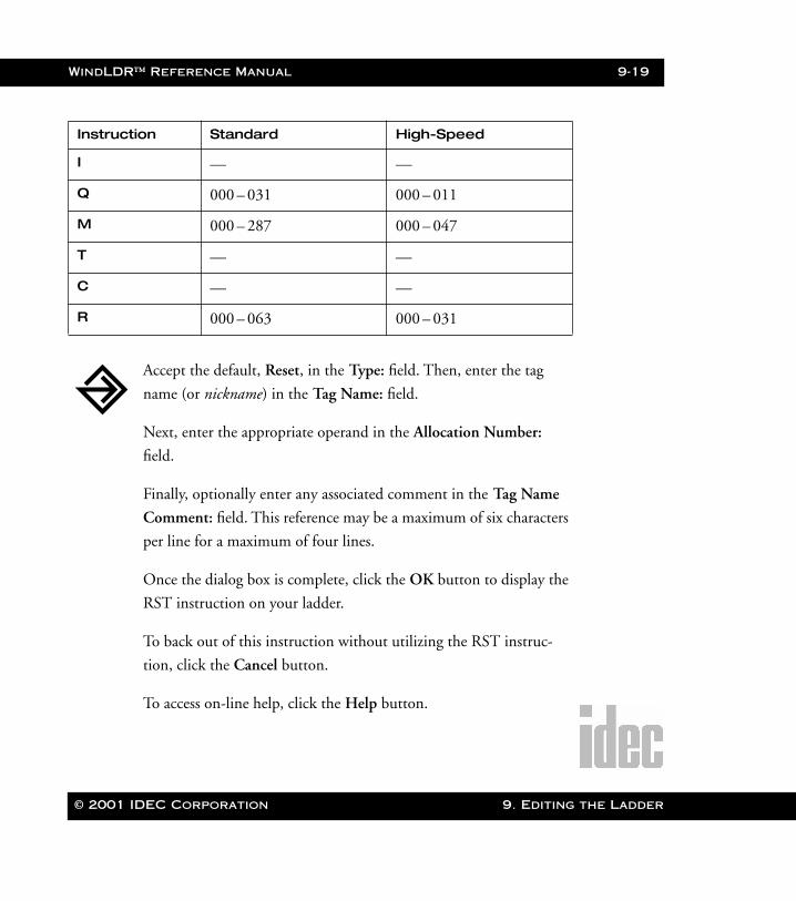
WindLDR™ Reference Manual 9-19
WLDR ReferenceBook Page 19 Thursday, April 5, 2001 3:36 PM
Instruction Standard High-Speed
I — —
Q 000 – 031 000 – 011
M 000 – 287 000 – 047
T — —
C — —
R 000 – 063 000 – 031
Accept the default, Reset, in the Type: field. Then, enter the tag
name (or nickname) in the Tag Name: field.
Next, enter the appropriate operand in the Allocation Number:
field.
Finally, optionally enter any associated comment in the Tag Name
Comment: field. This reference may be a maximum of six characters
per line for a maximum of four lines.
Once the dialog box is complete, click the OK button to display the
RST instruction on your ladder.
To back out of this instruction without utilizing the RST instruc-
tion, click the Cancel button.
To access on-line help, click the Help button.
© 2001 IDEC Corporation 9. Editing the Ladder
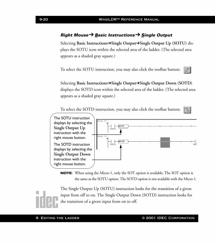
9-20 WindLDR™ Reference Manual
9. Editing t
ThdisSiinsrig
ThdisSiinsrig
WLDR ReferenceBook Page 20 Thursday, April 5, 2001 3:36 PM
Right Mouse➔ Basic Instructions➔ Single Output
Selecting Basic Instructions➔Single Output➔Single Output Up (SOTU) dis-
plays the SOTU icon within the selected area of the ladder. (The selected area
appears as a shaded gray square.)
To select the SOTU instruction, you may also click the toolbar button:
Selecting Basic Instructions➔Single Output➔Single Output Down (SOTD)
displays the SOTD icon within the selected area of the ladder. (The selected area
appears as a shaded gray square.)
To select the SOTD instruction, you may also click the toolbar button:
NOTE: When using the Micro-1, only the SOT option is available. The SOT option is
the same as the SOTU option. The SOTD option is not available with the Micro-1.
The Single Output Up (SOTU) instruction looks for the transition of a given
input from off to on. The Single Output Down (SOTD) instruction looks for
the transition of a given input from on to off.
e SOTU instruction plays by selecting the ngle Output Up truction with the ht mouse button.
e SOTD instruction plays by selecting the ngle Output Down truction with the ht mouse button.
he Ladder © 2001 IDEC Corporation
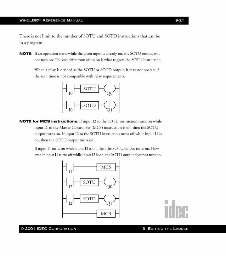
WindLDR™ Reference Manual 9-21
WLDR ReferenceBook Page 21 Thursday, April 5, 2001 3:36 PM
There is not limit to the number of SOTU and SOTD instructions that can be
in a program.
NOTE: If an operation starts while the given input is already on, the SOTU output will
not turn on. The transition from off to on is what triggers the SOTU instruction.
When a relay is defined as the SOTU or SOTD output, it may not operate if
the scan time is not compatible with relay requirements.
NOTE for MCS instructions: If input I2 to the SOTU instruction turns on while
input I1 to the Master Control Set (MCS) instruction is on, then the SOTU
output turns on. If input I2 to the SOTU instruction turns off while input I1 is
on, then the SOTD output turns on.
If input I1 turns on while input I2 is on, then the SOTU output turns on. How-
ever, if input I1 turns off while input I2 is on, the SOTD output does not turn on.
I0 Q1SOTD
I0 Q0SOTU
I2 Q1SOTD
I2 Q0SOTU
I1MCS
MCR
© 2001 IDEC Corporation 9. Editing the Ladder
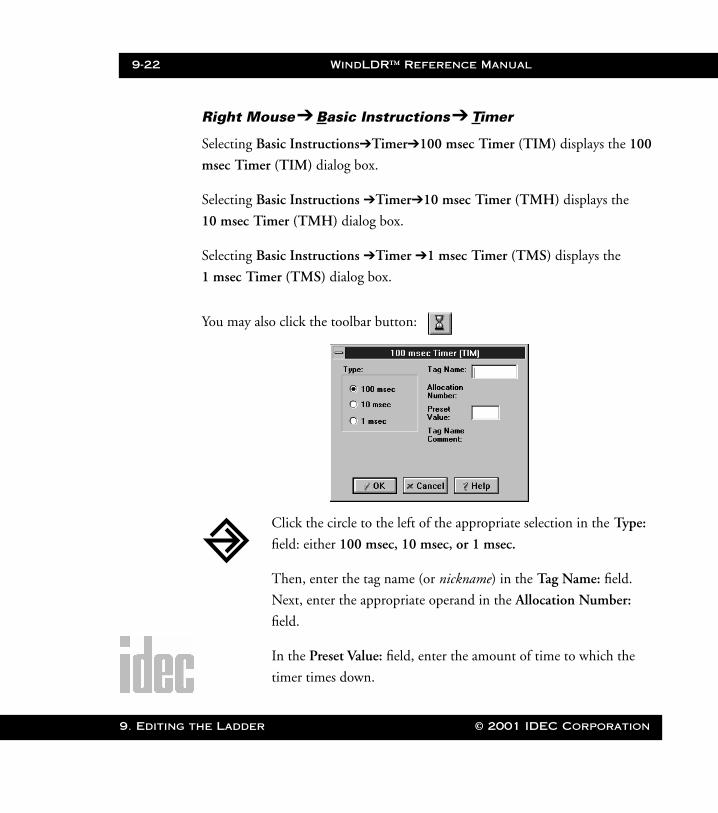
9-22 WindLDR™ Reference Manual
9. Editing t
WLDR ReferenceBook Page 22 Thursday, April 5, 2001 3:36 PM
Right Mouse➔ Basic Instructions➔ Timer e
Selecting Basic Instructions➔Timer➔100 msec Timer (TIM) displays the 100
msec Timer (TIM) dialog box.
Selecting Basic Instructions ➔Timer➔10 msec Timer (TMH) displays the
10 msec Timer (TMH) dialog box.
Selecting Basic Instructions ➔Timer ➔1 msec Timer (TMS) displays the
1 msec Timer (TMS) dialog box.
You may also click the toolbar button:
Click the circle to the left of the appropriate selection in the Type:
field: either 100 msec, 10 msec, or 1 msec.
Then, enter the tag name (or nickname) in the Tag Name: field.
Next, enter the appropriate operand in the Allocation Number:
field.
In the Preset Value: field, enter the amount of time to which the
timer times down.
he Ladder © 2001 IDEC Corporation
WindLDR™ Reference Manual 9-23
WLDR ReferenceBook Page 23 Thursday, April 5, 2001 3:36 PM
Finally, optionally enter any associated comment in the Tag Name
Comment: field. This reference may be a maximum of six characters
per line for a maximum of four lines.
Once the dialog box is complete, click the OK button to display the
timer instruction on your ladder. To back out of this instruction
without setting up a timer, click the Cancel button.
To access on-line help, click the Help button.
NOTE: The right mouse button is context-sensitive to the specific PLC selected. This
chapter is written in reference to the Micro3 PLC. To access the right mouse
button instructions for another PLC, select the Configure ➔ PLC Selection
option.
Three types of timers are available: 100 msec countdown timer (TIM), 10 msec
countdown timer (TMH), and 1 msec countdown timer (TMS).
A total of 32 timers and counters can be programmed in the standard processing
mode. Each timer must be allocated to a unique number, 0 through 31. The
same number cannot be allocated for counters. In high-speed mode, timer num-
bers 0 through 15 are available.
The following table provides information about each available timer.
© 2001 IDEC Corporation 9. Editing the Ladder
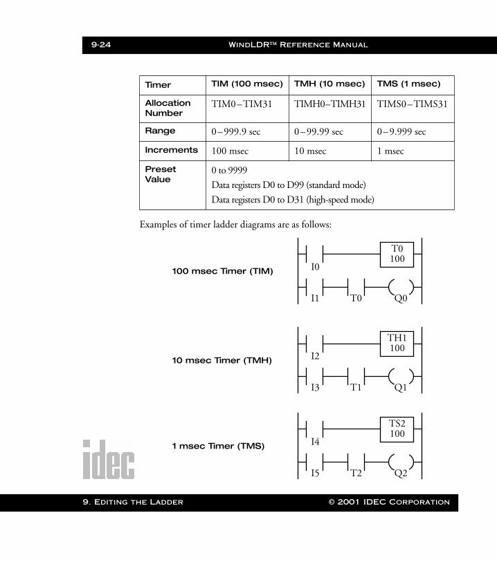
9-24 WindLDR™ Reference Manual
9. Editing t
WLDR ReferenceBook Page 24 Thursday, April 5, 2001 3:36 PM
Examples of timer ladder diagrams are as follows:
Timer TIM (100 msec) TMH (10 msec) TMS (1 msec)
Allocation Number
TIM0–TIM31 TIMH0–TIMH31 TIMS0–TIMS31
Range 0–999.9 sec 0–99.99 sec 0–9.999 sec
Increments 100 msec 10 msec 1 msec
Preset Value
0 to 9999
Data registers D0 to D99 (standard mode)
Data registers D0 to D31 (high-speed mode)
I0
T0
100
I1
T0
Q0
100 msec Timer (TIM)
10 msec Timer (TMH)
1 msec Timer (TMS)
I2
T1
100
I3
TH1
Q1
I4
T2
100
I5
TS2
Q2
he Ladder © 2001 IDEC Corporation
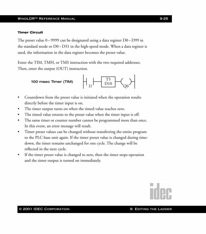
WindLDR™ Reference Manual 9-25
WLDR ReferenceBook Page 25 Thursday, April 5, 2001 3:36 PM
Timer Circuit
The preset value 0 – 9999 can be designated using a data register D0 – D99 in
the standard mode or D0 – D31 in the high-speed mode. When a data register is
used, the information in the data register becomes the preset value.
Enter the TIM, TMH, or TMS instruction with the two required addresses.
Then, enter the output (OUT) instruction.
• Countdown from the preset value is initiated when the operation results directly before the timer input is on.
• The timer output turns on when the timed value reaches zero.• The timed value returns to the preset value when the timer input is off.• The same timer or counter number cannot be programmed more than once.
In this event, an error message will result.• Timer preset values can be changed without transferring the entire program
to the PLC base unit again. If the timer preset value is changed during time-down, the timer remains unchanged for one cycle. The change will be reflected in the next cycle.
• If the timer preset value is changed to zero, then the timer stops operation and the timer output is turned on immediately.
I1 Q0100 msec Timer (TIM) D10
T5
© 2001 IDEC Corporation 9. Editing the Ladder
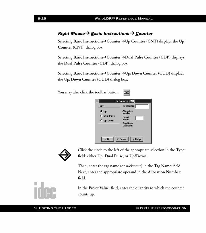
9-26 WindLDR™ Reference Manual
9. Editing t
WLDR ReferenceBook Page 26 Thursday, April 5, 2001 3:36 PM
Right Mouse➔ Basic Instructions➔ Counter
Selecting Basic Instructions➔Counter ➔Up Counter (CNT) displays the Up
Counter (CNT) dialog box.
Selecting Basic Instructions➔Counter ➔Dual Pulse Counter (CDP) displays
the Dual Pulse Counter (CDP) dialog box.
Selecting Basic Instructions➔Counter ➔Up/Down Counter (CUD) displays
the Up/Down Counter (CUD) dialog box.
You may also click the toolbar button:
Click the circle to the left of the appropriate selection in the Type:
field: either Up, Dual Pulse, or Up/Down.
Then, enter the tag name (or nickname) in the Tag Name: field.
Next, enter the appropriate operand in the Allocation Number:
field.
In the Preset Value: field, enter the quantity to which the counter
counts up.
he Ladder © 2001 IDEC Corporation
WindLDR™ Reference Manual 9-27
WLDR ReferenceBook Page 27 Thursday, April 5, 2001 3:36 PM
Finally, optionally enter any associated comment in the Tag Name
Comment: field. This reference may be a maximum of six characters
per line for a maximum of four lines.
Once the dialog box is complete, click the OK button to display the
counter instruction on your ladder. To back out of this instruction
without setting up a counter, click the Cancel button.
To access on-line help, click the Help button.
NOTE: The right mouse button is context-sensitive to the specific PLC selected. This
chapter is written in reference to the Micro3 PLC. To access the right mouse
button instructions for another PLC, select the Configure ➔ PLC Selection
option.
Three types of counters are available: dual pulse reversible counter (CNT0), up/
down selection reversible counter (CNT1), and adding (up) counters (CNT2–
CNT31).
A total of 32 timers and counters can be programmed in the standard processing
mode. Each counter must be allocated to a unique number (0 – 31). The same
number cannot be used for timers. In the high-speed processing mode, counter
numbers 0 – 15 are available.
The following table provides information about each available counters.
© 2001 IDEC Corporation 9. Editing the Ladder
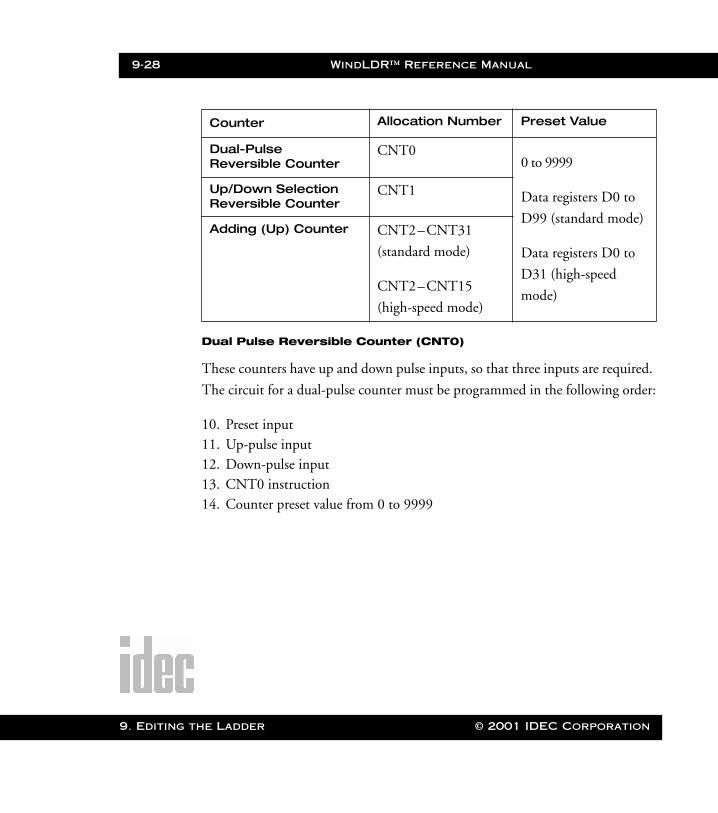
9-28 WindLDR™ Reference Manual
9. Editing t
WLDR ReferenceBook Page 28 Thursday, April 5, 2001 3:36 PM
Dual Pulse Reversible Counter (CNT0)
These counters have up and down pulse inputs, so that three inputs are required.
The circuit for a dual-pulse counter must be programmed in the following order:
10. Preset input11. Up-pulse input12. Down-pulse input13. CNT0 instruction14. Counter preset value from 0 to 9999
Counter Allocation Number Preset Value
Dual-Pulse Reversible Counter
CNT00 to 9999
Data registers D0 to
D99 (standard mode)
Data registers D0 to
D31 (high-speed
mode)
Up/Down Selection Reversible Counter
CNT1
Adding (Up) Counter CNT2–CNT31
(standard mode)
CNT2–CNT15
(high-speed mode)
he Ladder © 2001 IDEC Corporation
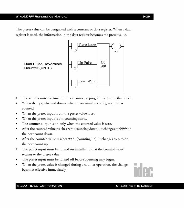
WindLDR™ Reference Manual 9-29
WLDR ReferenceBook Page 29 Thursday, April 5, 2001 3:36 PM
The preset value can be designated with a constant or data register. When a data
register is used, the information in the data register becomes the preset value.
• The same counter or timer number cannot be programmed more than once.• When the up-pulse and down-pulse are on simultaneously, no pulse is
counted.• When the preset input is on, the preset value is set.• When the preset input is off, counting starts.• The counter output is on only when the counted value is zero.• After the counted value reaches zero (counting down), it changes to 9999 on
the next count down.• After the counted value reaches 9999 (counting up), it changes to zero on
the next count up. • The preset input must be turned on initially, so that the counted value
returns to the preset value.• The preset input must be turned off before counting may begin.• When the preset value is changed during a counter operation, the change
becomes effective immediately.
I0 Q0
Dual Pulse Reversible Counter (CNT0) I1
I2
Preset Input
Up-Pulse
Down-Pulse
500C0
© 2001 IDEC Corporation 9. Editing the Ladder
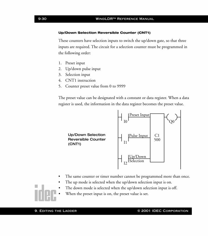
9-30 WindLDR™ Reference Manual
9. Editing t
WLDR ReferenceBook Page 30 Thursday, April 5, 2001 3:36 PM
Up/Down Selection Reversible Counter (CNT1)
These counters have selection inputs to switch the up/down gate, so that three
inputs are required. The circuit for a selection counter must be programmed in
the following order:
1. Preset input2. Up/down pulse input3. Selection input4. CNT1 instruction5. Counter preset value from 0 to 9999
The preset value can be designated with a constant or data register. When a data
register is used, the information in the data register becomes the preset value.
• The same counter or timer number cannot be programmed more than once.• The up mode is selected when the up/down selection input is on.• The down mode is selected when the up/down selection input is off.• When the preset input is on, the preset value is set.
I0 Q0
Up/Down Selection Reversible Counter
I1
I2
Preset Input
Pulse Input
Up/Down
500C1
(CNT1)
Selection
he Ladder © 2001 IDEC Corporation
WindLDR™ Reference Manual 9-31
WLDR ReferenceBook Page 31 Thursday, April 5, 2001 3:36 PM
• The counter output is on only when the counted value is zero.• After the counted value reaches zero (counting down), it changes to 9999 on
the next count down.• After the counted value reaches 9999 (counting up), it changes to zero on
the next count up. • The preset input must be turned on initially, so that the counted value
returns to the preset value.• The preset input must be turned off before counting may begin.• When the preset value is changed during a counter operation, the change
becomes effective immediately.
Adding (Up) Counters (CNT2–CNT31)
Standard counter circuits, using the CNT instruction, feature an adding (UP)
counter. There are 30 adding counters (CNT2 – CNT31) in the standard pro-
cessing mode or 14 adding counters in the high-speed mode.
When counter instructions are programmed, two addresses are required. The cir-
cuit for a adding (UP) counter must be programmed in the following order:
1. Reset input2. Pulse input3. CNT instruction4. Counter number from 2 to 315. Counter preset value from 0 to 9999
© 2001 IDEC Corporation 9. Editing the Ladder
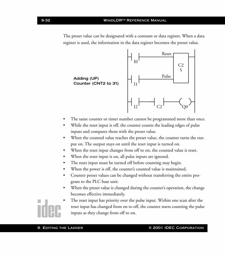
9-32 WindLDR™ Reference Manual
9. Editing t
WLDR ReferenceBook Page 32 Thursday, April 5, 2001 3:36 PM
The preset value can be designated with a constant or data register. When a data
register is used, the information in the data register becomes the preset value.
• The same counter or timer number cannot be programmed more than once.• While the reset input is off, the counter counts the leading edges of pulse
inputs and compares them with the preset value.• When the counted value reaches the preset value, the counter turns the out-
put on. The output stays on until the reset input is turned on. • When the reset input changes from off to on, the counted value is reset.• When the reset input is on, all pulse inputs are ignored.• The reset input must be turned off before counting may begin.• When the power is off, the counter’s counted value is maintained.• Counter preset values can be changed without transferring the entire pro-
gram to the PLC base unit.• When the preset value is changed during the counter’s operation, the change
becomes effective immediately.• The reset input has priority over the pulse input. Within one scan after the
reset input has changed from on to off, the counter starts counting the pulse inputs as they change from off to on.
I0
Q0
Adding (UP) Counter (CNT2 to 31) I1
I2
Reset
Pulse5
C2
C2
he Ladder © 2001 IDEC Corporation

WindLDR™ Reference Manual 9-33
WLDR ReferenceBook Page 33 Thursday, April 5, 2001 3:36 PM
Right Mouse➔ Basic Instructions➔ Shift Register
Selecting Basic Instructions➔Shift Register ➔Forward (SFR) displays the For-
ward Shift Register (SFR) dialog box.
Selecting Basic Instructions➔Shift Register ➔Reverse (SFRN) displays the
Reverse Shift Register (SFRN) dialog box.
You may also click the toolbar button:
Click the circle to the left of the appropriate selection in the Type:
field: either Forward or Reverse.
Then, enter the tag name (or nickname) in the Tag Name: field.
Next, enter the appropriate operand in the Allocation Number:
field.
In the Preset Value: field, enter the number of bits to shift.
Finally, optionally enter any associated comment in the Tag Name
Comment: field. This reference may be a maximum of six characters
per line for a maximum of four lines.
© 2001 IDEC Corporation 9. Editing the Ladder
9-34 WindLDR™ Reference Manual
9. Editing t
WLDR ReferenceBook Page 34 Thursday, April 5, 2001 3:36 PM
Once the dialog box is complete, click the OK button to display the
shift register instruction on your ladder.
To back out of this instruction without setting up a shift register,
click the Cancel button.
To access on-line help, click the Help button.
NOTE: The right mouse button is context-sensitive to the specific PLC selected. This
chapter is written in reference to the Micro3 PLC. To access the right mouse
button instructions for another PLC, select the Configure ➔ PLC Selection
option.
Two types of shift registers are available: forward (SFR) and reverse (SFRN). A
total of 64 bits are allocated to R0 through R63 in the standard processing mode.
In the high-speed processing mode, 32 bits are available for the shift register allo-
cated to R0 through R31.
Any number of available bits can be selected to form a train of bits which store
the on or off status. The on/off data of constituent bits is shifted in the forward
direction (forward shift register) or in the reverse direction (reverse shift register)
when a pulse input is turned on.
Forward Shift Register (SFR)
When SFR instructions are programmed, two addresses are always required.
Enter the SFR instruction, followed by a shift register number selected from the
appropriate operand numbers. The shift register number corresponds to the first
bit. The number of bits is the second required address after the SFR instruction.
he Ladder © 2001 IDEC Corporation
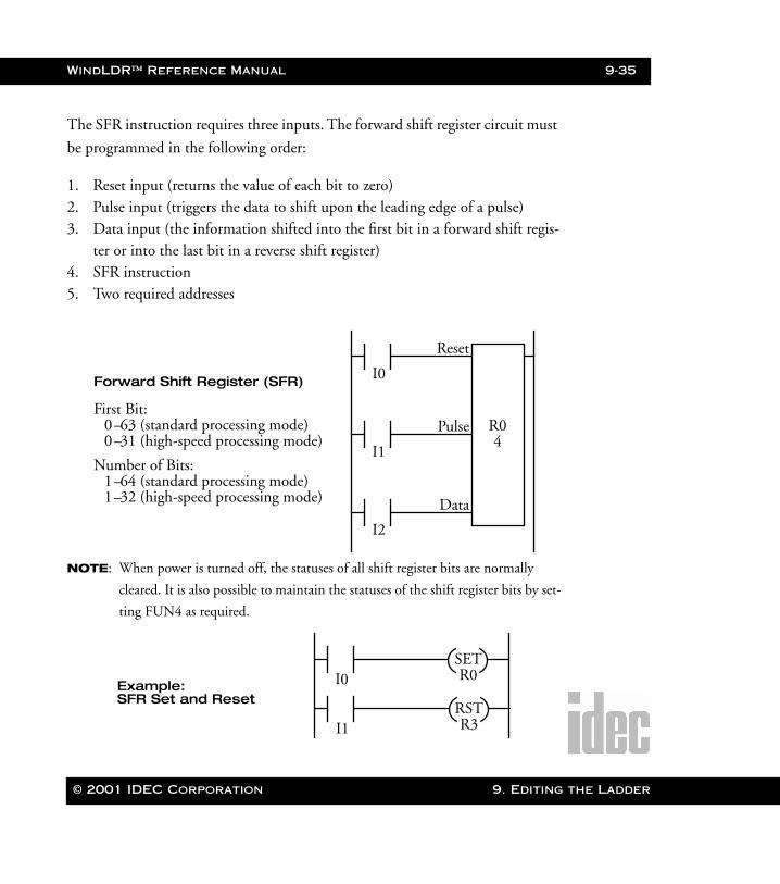
WindLDR™ Reference Manual 9-35
WLDR ReferenceBook Page 35 Thursday, April 5, 2001 3:36 PM
The SFR instruction requires three inputs. The forward shift register circuit must
be programmed in the following order:
1. Reset input (returns the value of each bit to zero)2. Pulse input (triggers the data to shift upon the leading edge of a pulse)3. Data input (the information shifted into the first bit in a forward shift regis-
ter or into the last bit in a reverse shift register)4. SFR instruction5. Two required addresses
NOTE: When power is turned off, the statuses of all shift register bits are normally
cleared. It is also possible to maintain the statuses of the shift register bits by set-
ting FUN4 as required.
I0Forward Shift Register (SFR)
I1
I2
Reset
Pulse
Data
4R0
First Bit: 0–63 (standard processing mode)0–31 (high-speed processing mode)
Number of Bits:1–64 (standard processing mode)1–32 (high-speed processing mode)
I0Example:
SETR0
I1RSTR3
SFR Set and Reset
© 2001 IDEC Corporation 9. Editing the Ladder
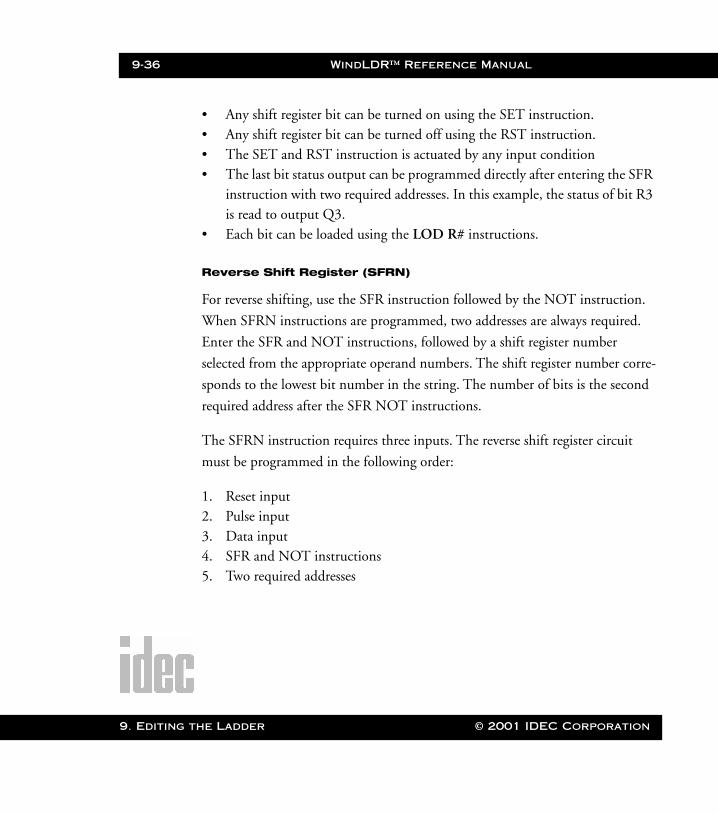
9-36 WindLDR™ Reference Manual
9. Editing t
WLDR ReferenceBook Page 36 Thursday, April 5, 2001 3:36 PM
• Any shift register bit can be turned on using the SET instruction.• Any shift register bit can be turned off using the RST instruction.• The SET and RST instruction is actuated by any input condition• The last bit status output can be programmed directly after entering the SFR
instruction with two required addresses. In this example, the status of bit R3 is read to output Q3.
• Each bit can be loaded using the LOD R# instructions.
Reverse Shift Register (SFRN)
For reverse shifting, use the SFR instruction followed by the NOT instruction.
When SFRN instructions are programmed, two addresses are always required.
Enter the SFR and NOT instructions, followed by a shift register number
selected from the appropriate operand numbers. The shift register number corre-
sponds to the lowest bit number in the string. The number of bits is the second
required address after the SFR NOT instructions.
The SFRN instruction requires three inputs. The reverse shift register circuit
must be programmed in the following order:
1. Reset input 2. Pulse input 3. Data input 4. SFR and NOT instructions5. Two required addresses
he Ladder © 2001 IDEC Corporation
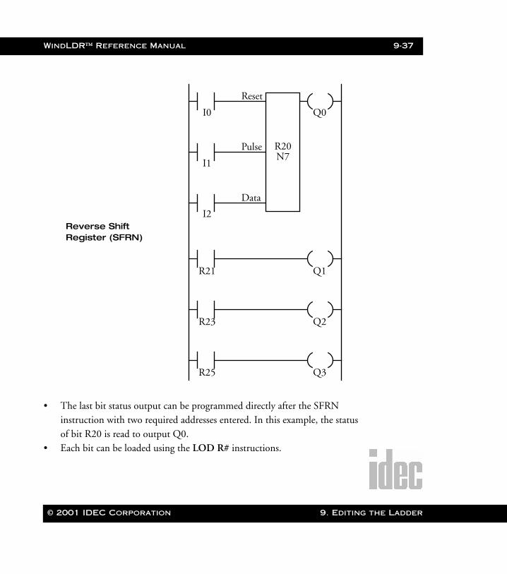
WindLDR™ Reference Manual 9-37
WLDR ReferenceBook Page 37 Thursday, April 5, 2001 3:36 PM
• The last bit status output can be programmed directly after the SFRN instruction with two required addresses entered. In this example, the status of bit R20 is read to output Q0.
• Each bit can be loaded using the LOD R# instructions.
I0 Q0
Reverse Shift Register (SFRN)
I1
I2
Reset
Pulse
Data
N7R20
R21 Q1
R23 Q2
R25 Q3
© 2001 IDEC Corporation 9. Editing the Ladder

9-38 WindLDR™ Reference Manual
9. Editing t
WLDR ReferenceBook Page 38 Thursday, April 5, 2001 3:36 PM
Bi-Directional Shift Register
A bi-directional shift register can be created by first entering in the SFR instruc-
tion (with two addresses) as explained in the Forward Shift Register (SFR) section
on page 9-34. Then, enter the SFR and NOT instructions (with two addresses)
as explained in the Reverse Shift Register (SFRN) section on page 9-36.
I0
Bi-Directional Shift Register
I1
I2
Reset
Pulse
Data
N6R22
R23 Q0
I3
I4
I5
Reset
Pulse
Data
N6R22
R24 Q1
R26 Q2
he Ladder © 2001 IDEC Corporation
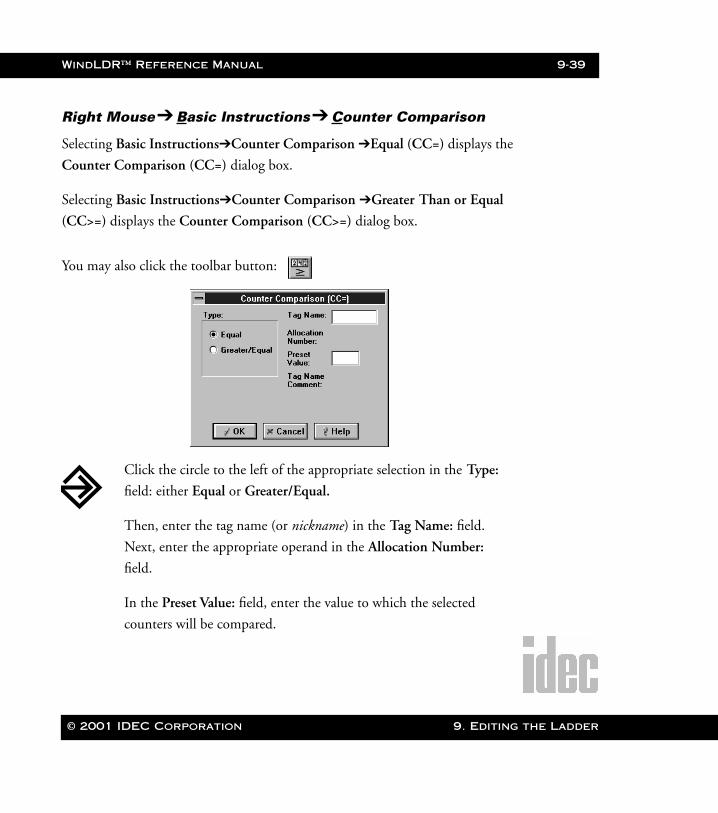
WindLDR™ Reference Manual 9-39
WLDR ReferenceBook Page 39 Thursday, April 5, 2001 3:36 PM
Right Mouse➔ Basic Instructions➔ Counter Comparison
Selecting Basic Instructions➔Counter Comparison ➔Equal (CC=) displays the
Counter Comparison (CC=) dialog box.
Selecting Basic Instructions➔Counter Comparison ➔Greater Than or Equal
(CC>=) displays the Counter Comparison (CC>=) dialog box.
You may also click the toolbar button:
Click the circle to the left of the appropriate selection in the Type:
field: either Equal or Greater/Equal.
Then, enter the tag name (or nickname) in the Tag Name: field.
Next, enter the appropriate operand in the Allocation Number:
field.
In the Preset Value: field, enter the value to which the selected
counters will be compared.
© 2001 IDEC Corporation 9. Editing the Ladder

9-40 WindLDR™ Reference Manual
9. Editing t
WLDR ReferenceBook Page 40 Thursday, April 5, 2001 3:36 PM
Finally, optionally enter any associated comment in the Tag Name
Comment: field. This reference may be a maximum of six characters
per line for a maximum of four lines.
Once the dialog box is complete, click the OK button to display the
counter comparison instruction on your ladder.
To back out of this instruction without setting up a counter compar-
ison instruction, click the Cancel button.
To access on-line help, click the Help button.
NOTE: The right mouse button is context-sensitive to the specific PLC selected. This
chapter is written in reference to the Micro3 PLC. To access the right mouse
button instructions for another PLC, select the Configure ➔ PLC Selection
option.
The CC= instruction is an equivalent comparison instruction for counted values.
This instruction will constantly compare counted values to the value that has been
programmed. When the counter value equals the given value, the coil turns on.
The CC>= instruction is an equal to or greater than comparison instruction for
counted values. This instruction will constantly compare counted values to the
value that has been programmed. When the counter value is equal to or greater
than the given value, the coil turns on.
When a counter comparison instruction is programmed, two addresses are
required. The circuit for a counter comparison must be programmed in the fol-
lowing order:
he Ladder © 2001 IDEC Corporation
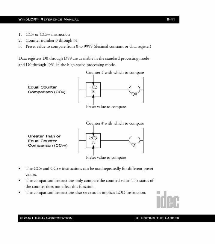
WindLDR™ Reference Manual 9-41
WLDR ReferenceBook Page 41 Thursday, April 5, 2001 3:36 PM
1. CC= or CC>= instruction2. Counter number 0 through 313. Preset value to compare from 0 to 9999 (decimal constant or data register)
Data registers D0 through D99 are available in the standard processing mode
and D0 through D31 in the high-speed processing mode.
• The CC= and CC>= instructions can be used repeatedly for different preset values.
• The comparison instructions only compare the counted value. The status of the counter does not affect this function.
• The comparison instructions also serve as an implicit LOD instruction.
Equal Counter Comparison (CC=)
=C210 Q0
Counter # with which to compare
Preset value to compare
Greater Than or Equal Counter
≥C315 Q1
Counter # with which to compare
Preset value to compare
Comparison (CC>=)
© 2001 IDEC Corporation 9. Editing the Ladder

9-42 WindLDR™ Reference Manual
9. Editing t
The MCSdisplays wing MasteSet (MCS
The MCRdisplays wing MasteReset (M
WLDR ReferenceBook Page 42 Thursday, April 5, 2001 3:36 PM
• Like the LOD instruction, the comparison instructions can be followed by the AND or OR instructions.
• Another way to accomplish the above is to use comparison instructions which are then followed by the AND LOD or OR LOD instructions.
Right Mouse➔ Basic Instructions➔ Program Flow➔ MasterControl Set (MCS) and Master Control Reset (MCR)Selecting Basic Instructions➔Program Flow ➔Master Control Set (MCS) auto-
matically displays the instructions associated with the master control set.
You may also click the toolbar button:
Selecting Basic Instructions➔Program Flow ➔Master Control Reset (MCR)
automatically displays the instructions associated with the master control reset.
You may also click the toolbar button:
NOTE: The right mouse button is context-sensitive to the specific PLC selected. This
chapter is written in reference to the Micro3 PLC. To access the right mouse
button instructions for another PLC, select the Configure ➔ PLC Selection
option.
function hen select-r Control ).
function hen select-r Control CR).
he Ladder © 2001 IDEC Corporation
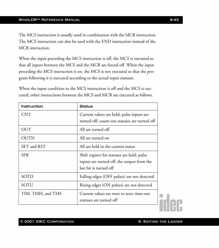
WindLDR™ Reference Manual 9-43
WLDR ReferenceBook Page 43 Thursday, April 5, 2001 3:36 PM
The MCS instruction is usually used in combination with the MCR instruction.
The MCS instruction can also be used with the END instruction instead of the
MCR instruction.
When the input preceding the MCS instruction is off, the MCS is executed so
that all inputs between the MCS and the MCR are forced off. When the input
preceding the MCS instruction is on, the MCS is not executed so that the pro-
gram following it is executed according to the actual input statuses.
When the input condition to the MCS instruction is off and the MCS is exe-
cuted, other instructions between the MCS and MCR are executed as follows.
Instruction Status
CNT Current values are held; pulse inputs are
turned off; count-out statuses are turned off
OUT All are turned off
OUTN All are turned on
SET and RST All are held in the current status
SFR Shift register bit statuses are held; pulse
inputs are turned off; the output from the
last bit is turned off
SOTD Falling edges (OFF pulses) are not detected
SOTU Rising edges (ON pulses) are not detected
TIM, TMH, and TMS Current values are reset to zero; time-out
statuses are turned off
© 2001 IDEC Corporation 9. Editing the Ladder
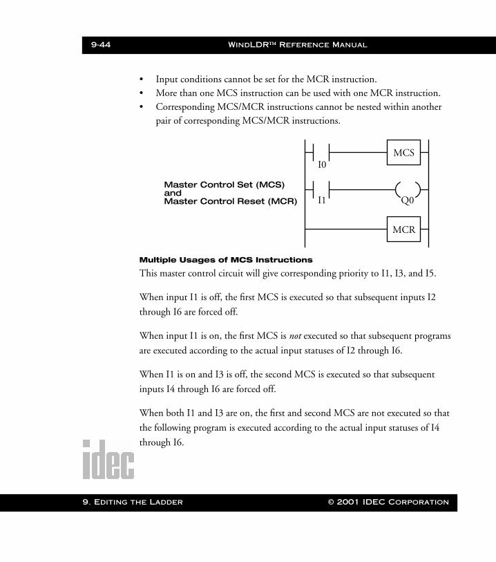
9-44 WindLDR™ Reference Manual
9. Editing t
WLDR ReferenceBook Page 44 Thursday, April 5, 2001 3:36 PM
• Input conditions cannot be set for the MCR instruction.• More than one MCS instruction can be used with one MCR instruction.• Corresponding MCS/MCR instructions cannot be nested within another
pair of corresponding MCS/MCR instructions.
Multiple Usages of MCS Instructions
This master control circuit will give corresponding priority to I1, I3, and I5.
When input I1 is off, the first MCS is executed so that subsequent inputs I2
through I6 are forced off.
When input I1 is on, the first MCS is not executed so that subsequent programs
are executed according to the actual input statuses of I2 through I6.
When I1 is on and I3 is off, the second MCS is executed so that subsequent
inputs I4 through I6 are forced off.
When both I1 and I3 are on, the first and second MCS are not executed so that
the following program is executed according to the actual input statuses of I4
through I6.
I0
I1
MCS
Q0
Master Control Set (MCS)
MCR
andMaster Control Reset (MCR)
he Ladder © 2001 IDEC Corporation
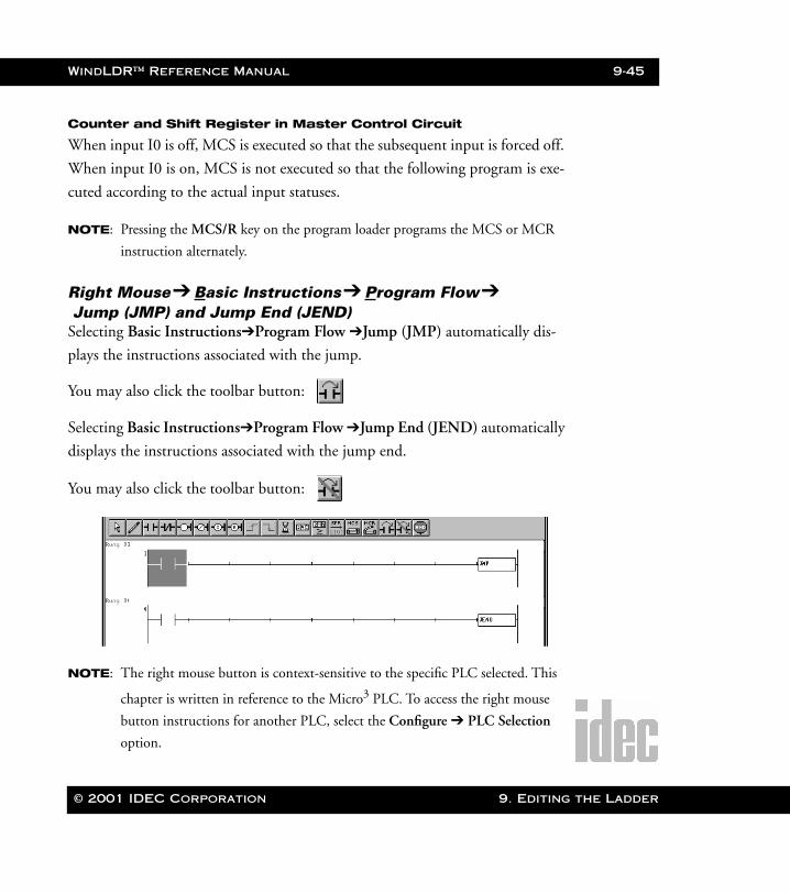
WindLDR™ Reference Manual 9-45
WLDR ReferenceBook Page 45 Thursday, April 5, 2001 3:36 PM
Counter and Shift Register in Master Control Circuit
When input I0 is off, MCS is executed so that the subsequent input is forced off.
When input I0 is on, MCS is not executed so that the following program is exe-
cuted according to the actual input statuses.
NOTE: Pressing the MCS/R key on the program loader programs the MCS or MCR
instruction alternately.
Right Mouse➔ Basic Instructions➔ Program Flow➔ Jump (JMP) and Jump End (JEND)Selecting Basic Instructions➔Program Flow ➔Jump (JMP) automatically dis-
plays the instructions associated with the jump.
You may also click the toolbar button:
Selecting Basic Instructions➔Program Flow ➔Jump End (JEND) automatically
displays the instructions associated with the jump end.
You may also click the toolbar button:
NOTE: The right mouse button is context-sensitive to the specific PLC selected. This
chapter is written in reference to the Micro3 PLC. To access the right mouse
button instructions for another PLC, select the Configure ➔ PLC Selection
option.
© 2001 IDEC Corporation 9. Editing the Ladder

9-46 WindLDR™ Reference Manual
9. Editing t
WLDR ReferenceBook Page 46 Thursday, April 5, 2001 3:36 PM
The JMP instruction is usually used in combination with the JEND instruction.
At the end of a program, the JMP instruction can also be used with the END
instruction, instead of the JEND instruction.
These instructions are used to proceed through the portion of the program
between the JMP and JEND without processing.
When the operation instruction immediately before the JMP instruction is on,
the JMP is valid and the program is not executed. When the operation result
immediately before the JMP instruction is off, the JMP is invalid and the pro-
gram is executed.
When the input condition to the JMP instruction is on and the JMP is executed,
other instructions between the JMP and JEND are executed as follows.
Instruction Status
SOTU Rising edges (ON pulses) are not detected
SOTD Falling edges (OFF pulses) are not detected
OUT and OUTN All are held in the current status
SET and RST All are held in the current status
TIM, TMH, and TMS Current values and time-out statuses are held
CNT Current values are held; pulse inputs are
turned off; count-out statuses held
SFR Shift register bit statuses are held; pulse
inputs are turned off; the output from the
last bit is held
he Ladder © 2001 IDEC Corporation
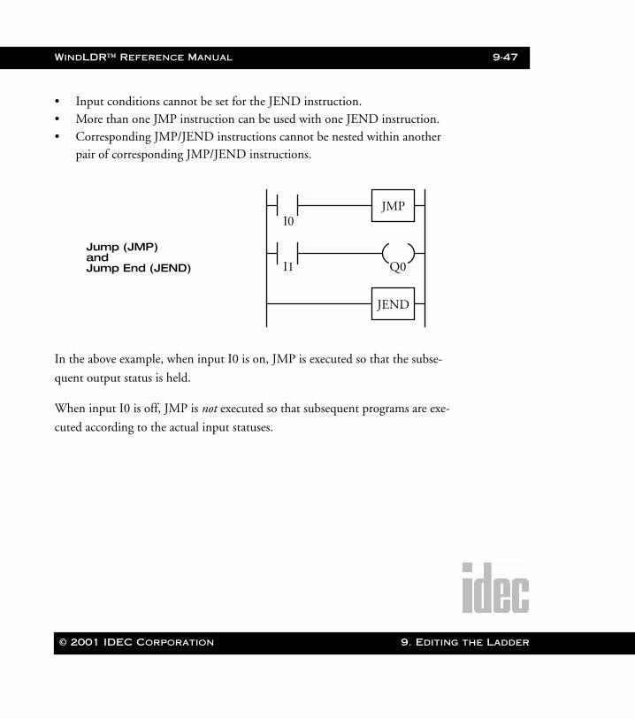
WindLDR™ Reference Manual 9-47
WLDR ReferenceBook Page 47 Thursday, April 5, 2001 3:36 PM
• Input conditions cannot be set for the JEND instruction.• More than one JMP instruction can be used with one JEND instruction.• Corresponding JMP/JEND instructions cannot be nested within another
pair of corresponding JMP/JEND instructions.
In the above example, when input I0 is on, JMP is executed so that the subse-
quent output status is held.
When input I0 is off, JMP is not executed so that subsequent programs are exe-
cuted according to the actual input statuses.
I0
I1
JMP
Q0
Jump (JMP)
JEND
andJump End (JEND)
© 2001 IDEC Corporation 9. Editing the Ladder
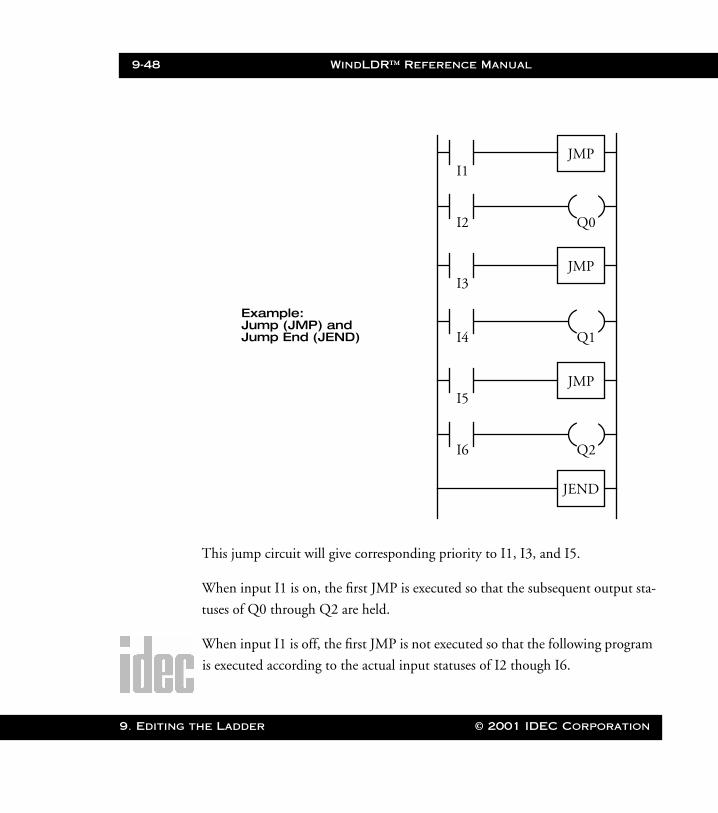
9-48 WindLDR™ Reference Manual
9. Editing t
WLDR ReferenceBook Page 48 Thursday, April 5, 2001 3:36 PM
This jump circuit will give corresponding priority to I1, I3, and I5.
When input I1 is on, the first JMP is executed so that the subsequent output sta-
tuses of Q0 through Q2 are held.
When input I1 is off, the first JMP is not executed so that the following program
is executed according to the actual input statuses of I2 though I6.
I1
I2
JMP
Q0
Example:
JEND
Jump (JMP) andJump End (JEND)
I3
I4
JMP
Q1
I5
I6
JMP
Q2
he Ladder © 2001 IDEC Corporation
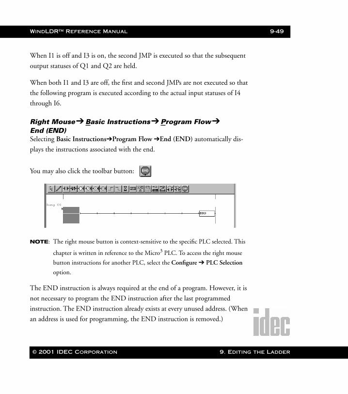
WindLDR™ Reference Manual 9-49
WLDR ReferenceBook Page 49 Thursday, April 5, 2001 3:36 PM
When I1 is off and I3 is on, the second JMP is executed so that the subsequent
output statuses of Q1 and Q2 are held.
When both I1 and I3 are off, the first and second JMPs are not executed so that
the following program is executed according to the actual input statuses of I4
through I6.
Right Mouse➔ Basic Instructions➔ Program Flow➔ End (END)Selecting Basic Instructions➔Program Flow ➔End (END) automatically dis-
plays the instructions associated with the end.
You may also click the toolbar button:
NOTE: The right mouse button is context-sensitive to the specific PLC selected. This
chapter is written in reference to the Micro3 PLC. To access the right mouse
button instructions for another PLC, select the Configure ➔ PLC Selection
option.
The END instruction is always required at the end of a program. However, it is
not necessary to program the END instruction after the last programmed
instruction. The END instruction already exists at every unused address. (When
an address is used for programming, the END instruction is removed.)
© 2001 IDEC Corporation 9. Editing the Ladder
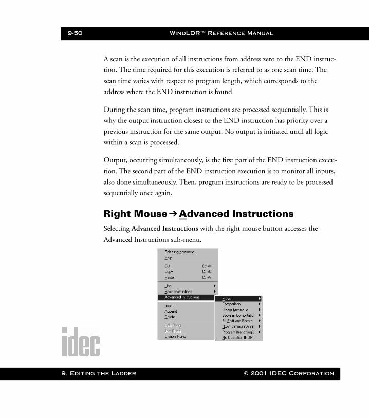
9-50 WindLDR™ Reference Manual
9. Editing t
WLDR ReferenceBook Page 50 Thursday, April 5, 2001 3:36 PM
A scan is the execution of all instructions from address zero to the END instruc-
tion. The time required for this execution is referred to as one scan time. The
scan time varies with respect to program length, which corresponds to the
address where the END instruction is found.
During the scan time, program instructions are processed sequentially. This is
why the output instruction closest to the END instruction has priority over a
previous instruction for the same output. No output is initiated until all logic
within a scan is processed.
Output, occurring simultaneously, is the first part of the END instruction execu-
tion. The second part of the END instruction execution is to monitor all inputs,
also done simultaneously. Then, program instructions are ready to be processed
sequentially once again.
Right Mouse ➔Advanced InstructionsSelecting Advanced Instructions with the right mouse button accesses the
Advanced Instructions sub-menu.
he Ladder © 2001 IDEC Corporation

WindLDR™ Reference Manual 9-51
WLDR ReferenceBook Page 51 Thursday, April 5, 2001 3:36 PM
NOTE: The right mouse button is context-sensitive to the specific PLC selected. This
chapter is written in reference to the Micro3 PLC. To access the right mouse
button instructions for another PLC, select the Configure ➔ PLC Selection
option.
Group # Symbol Name Addr’s Available on
NOP 0 NOP No operation 1 All Micro3
base units
Move 11 MOV Move 3 or 4
All Micro3
base units
12 MOVN Move not 3 or 4
13 IMOV Indirect move 5 or 6
14 IMOVN Indirect move not 5 or 6
— Macro Macro instruction —
Com-
parison
21 CMP= Compare equal to 4 or 5
All Micro3
base units
22 CMP<> Compare unequal
to
4 or 5
23 CMP< Compare less than 4 or 5
24 CMP> Compare greater
than
4 or 5
25 CMP<= Compare less
than or equal to
4 or 5
26 CMP>= Compare greater
than or equal to
4 or 5
© 2001 IDEC Corporation 9. Editing the Ladder
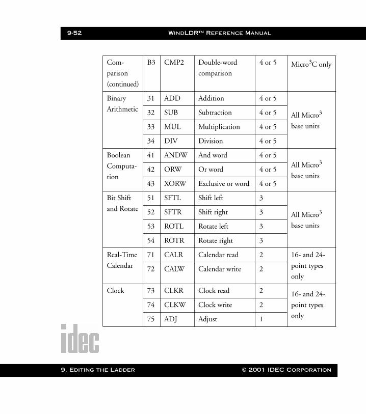
9-52 WindLDR™ Reference Manual
9. Editing t
WLDR ReferenceBook Page 52 Thursday, April 5, 2001 3:36 PM
Com-
parison
(continued)
B3 CMP2 Double-word
comparison
4 or 5 Micro3C only
Binary
Arithmetic
31 ADD Addition 4 or 5
All Micro3
base units
32 SUB Subtraction 4 or 5
33 MUL Multiplication 4 or 5
34 DIV Division 4 or 5
Boolean
Computa-
tion
41 ANDW And word 4 or 5All Micro3
base units42 ORW Or word 4 or 5
43 XORW Exclusive or word 4 or 5
Bit Shift
and Rotate
51 SFTL Shift left 3
All Micro3
base units
52 SFTR Shift right 3
53 ROTL Rotate left 3
54 ROTR Rotate right 3
Real-Time
Calendar
71 CALR Calendar read 2 16- and 24-
point types
only72 CALW Calendar write 2
Clock 73 CLKR Clock read 2 16- and 24-
point types
only
74 CLKW Clock write 2
75 ADJ Adjust 1
he Ladder © 2001 IDEC Corporation
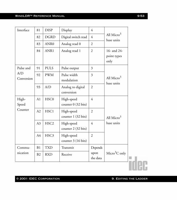
WindLDR™ Reference Manual 9-53
WLDR ReferenceBook Page 53 Thursday, April 5, 2001 3:36 PM
Interface 81 DISP Display 4All Micro3
base units82 DGRD Digital switch read 4
83 ANR0 Analog read 0 2
84 ANR1 Analog read 1 2 16- and 24-
point types
only
Pulse and
A/D
Conversion
91 PULS Pulse output 3
All Micro3
base units
92 PWM Pulse width
modulation
3
93 A/D Analog to digital
conversion
2
High-
Speed
Counter
A1 HSC0 High-speed
counter 0 (32 bits)
4
All Micro3
base units
A2 HSC1 High-speed
counter 1 (32 bits)
2
A3 HSC2 High-speed
counter 2 (32 bits)
4
A4 HSC3 High-speed
counter 3 (16 bits)
2
Commu-
nication
B1 TXD Transmit Depends
upon
the dataMicro3C onlyB2 RXD Receive
© 2001 IDEC Corporation 9. Editing the Ladder
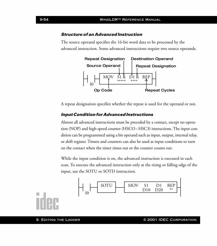
9-54 WindLDR™ Reference Manual
9. Editing t
WLDR ReferenceBook Page 54 Thursday, April 5, 2001 3:36 PM
Structure of an Advanced Instruction
The source operand specifies the 16-bit word data to be processed by the
advanced instruction. Some advanced instructions require two source operands.
A repeat designation specifies whether the repeat is used for the operand or not.
Input Condition for Advanced Instructions
Almost all advanced instructions must be preceded by a contact, except no opera-
tion (NOP) and high-speed counter (HSCO–HSC3) instructions. The input con-
dition can be programmed using a bit operand such as input, output, internal relay,
or shift register. Timers and counters can also be used as input conditions to turn
on the contact when the timer times out or the counter counts out.
While the input condition is on, the advanced instruction is executed in each
scan. To execute the advanced instruction only at the rising or falling edge of the
input, use the SOTU or SOTD instruction.
I0
MOV S1 R D1 R REP***** **** **
Op Code
Source Operand
Destination Operand
Repeat Cycles
Repeat Designation
Repeat Designation
I0
MOV S1 D1 REPD10 D20 **
SOTU
he Ladder © 2001 IDEC Corporation
WindLDR™ Reference Manual 9-55
WLDR ReferenceBook Page 55 Thursday, April 5, 2001 3:36 PM
Source and Destination Operands
The source and destination operands specify 16-bit word data. When a bit oper-
and such as input, output, internal relay, or shift register is designated as a source
or destination operand, 16 points (starting with the designated number) are pro-
cessed as source or destination data.
When a word operand such as timer or counter is designated as a source operand,
the current value is read as source data. When a timer or counter is designated as a
destination operand, the result of the advanced instruction is set to the preset value
for the timer or counter. When a data register is designated as a source or destina-
tion operand, the data is read from or written to the designated data register.
Using a Timer or Counter as a Source Operand
Since all timer instructions TIM (100 msec timer), TMH (10 msec timer), and
TMS (1-msec timer) subtract from the preset value, the current value is decre-
mented from the preset value and indicates the remaining time. As described
above, when a timer is designated as a source operand of an advanced instruc-
tion, the current value (or the remaining time) of the timer is read as source data.
Reversible counters CO and C1 start counting at the preset value, and the cur-
rent value is incremented or decremented from the preset value. Adding counters
C2 through C31 start counting at 0, and the current value is incremented up to
the preset value. When any counter is designated as a source operand of an
advanced instruction, the current value is read as source data.
© 2001 IDEC Corporation 9. Editing the Ladder
9-56 WindLDR™ Reference Manual
9. Editing t
WLDR ReferenceBook Page 56 Thursday, April 5, 2001 3:36 PM
Using a Timer or a Counter as Destination Operand
As described previously, when a timer or counter is designated as the destination
operand of an advanced instruction, the result of the advanced instruction is set
to the preset value of the timer or counter. Since timer and counter preset values
can be 0 through 9999, make sure that the result of the advanced instruction
does not exceed 9999. If the result to be set to a timer or counter designated as
the destination exceeds 9999, a user program execution error will result; then,
error indicator ERR1 is lit, and special internal relay M304 turns on.
When a timer or counter preset value is designated using a data register, the timer
or counter cannot be designated as the destination of an advanced instruction.
When executing such an advanced instruction, a user program execution error
will result. If a timer or counter is designated as the destination of an advanced
instruction and if the timer or counter is not programmed, then a user program
execution error will also result.
NOTE: When a user program execution error occurs, the result is not set to the destination.
he Ladder © 2001 IDEC Corporation
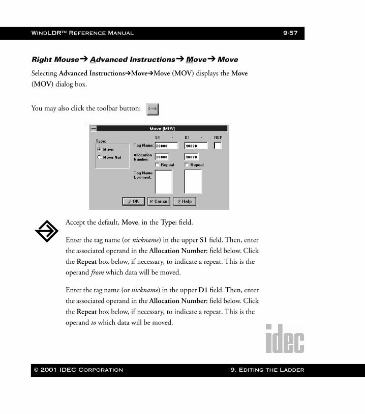
WindLDR™ Reference Manual 9-57
WLDR ReferenceBook Page 57 Thursday, April 5, 2001 3:36 PM
Right Mouse➔ Advanced Instructions➔ Move➔ Move
Selecting Advanced Instructions➔Move➔Move (MOV) displays the Move
(MOV) dialog box.
You may also click the toolbar button:
Accept the default, Move, in the Type: field.
Enter the tag name (or nickname) in the upper S1 field. Then, enter
the associated operand in the Allocation Number: field below. Click
the Repeat box below, if necessary, to indicate a repeat. This is the
operand from which data will be moved.
Enter the tag name (or nickname) in the upper D1 field. Then, enter
the associated operand in the Allocation Number: field below. Click
the Repeat box below, if necessary, to indicate a repeat. This is the
operand to which data will be moved.
© 2001 IDEC Corporation 9. Editing the Ladder
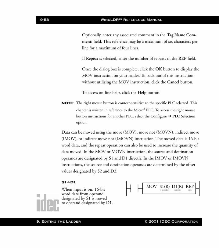
9-58 WindLDR™ Reference Manual
9. Editing t
WLDR ReferenceBook Page 58 Thursday, April 5, 2001 3:36 PM
Optionally, enter any associated comment in the Tag Name Com-
ment: field. This reference may be a maximum of six characters per
line for a maximum of four lines.
If Repeat is selected, enter the number of repeats in the REP field.
Once the dialog box is complete, click the OK button to display the
MOV instruction on your ladder. To back out of this instruction
without utilizing the MOV instruction, click the Cancel button.
To access on-line help, click the Help button.
NOTE: The right mouse button is context-sensitive to the specific PLC selected. This
chapter is written in reference to the Micro3 PLC. To access the right mouse
button instructions for another PLC, select the Configure ➔ PLC Selection
option.
Data can be moved using the move (MOV), move not (MOVN), indirect move
(IMOV), or indirect move not (IMOVN) instruction. The moved data is 16-bit
word data, and the repeat operation can also be used to increase the quantity of
data moved. In the MOV or MOVN instruction, the source and destination
operands are designated by S1 and D1 directly. In the IMOV or IMOVN
instructions, the source and destination operands are determined by the offset
values designated by S2 and D2.
MOV S1(R) D1(R) REP***** **** **
S1➔D1
When input is on, 16-bit word data from operand designated by S1 is moved to operand designated by D1.
he Ladder © 2001 IDEC Corporation

WindLDR™ Reference Manual 9-59
WLDR ReferenceBook Page 59 Thursday, April 5, 2001 3:36 PM
Operands Possible (Standard Processing Mode)
NOTE: When using these operands in the high-speed processing mode, possibilities are
limited.
When a timer (T) or counter (C) is used as S1, the timer/counter current value is
read out. When a T or C is used as D1, the data is written as a preset value which
can be 0 through 9999.
When a bit operand such as an input, output, internal relay, or shift register is
used as the source or destination, 16 points are used. When a repeat is designated
for a bit operand, the quantity of operand bits increases in 16-point increments.
Operand S1 (Source 1) D1 (Destination 1)
I 0 – 35 —
Q 0 – 31 0 – 31
M 0 – 317 0 – 287
T 0 – 31 0 – 31
C 0 – 31 0 – 31
R 0 – 63 0 – 63
D (Micro3) 0 – 99 0 – 99
D (Micro3C)
0 – 498 0 – 498
Constant 0 – 65535 —
Repeat 1 – 31 1 – 31
© 2001 IDEC Corporation 9. Editing the Ladder
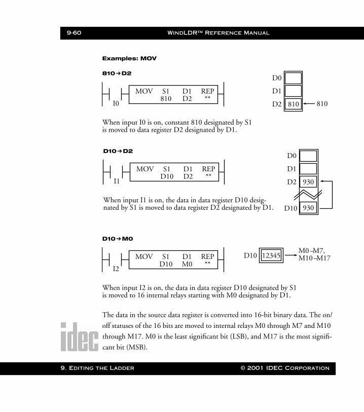
9-60 WindLDR™ Reference Manual
9. Editing t
WLDR ReferenceBook Page 60 Thursday, April 5, 2001 3:36 PM
Examples: MOV
The data in the source data register is converted into 16-bit binary data. The on/
off statuses of the 16 bits are moved to internal relays M0 through M7 and M10
through M17. M0 is the least significant bit (LSB), and M17 is the most signifi-
cant bit (MSB).
I0
MOV S1 D1 REP810 D2 **
810➔D2
When input I0 is on, constant 810 designated by S1 is moved to data register D2 designated by D1.
810
D0
D1
D2 810
I1
MOV S1 D1 REPD10 D2 **
D10➔D2
When input I1 is on, the data in data register D10 desig- nated by S1 is moved to data register D2 designated by D1.
930
D0
D1
D2
D10
I2
MOV S1 D1 REPD10 M0 **
D10➔M0
When input I2 is on, the data in data register D10 designated by S1is moved to 16 internal relays starting with M0 designated by D1.
12345D10M0 –M7,
930
M10 –M17
he Ladder © 2001 IDEC Corporation
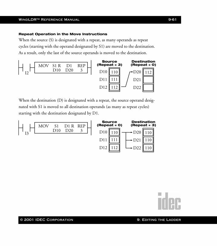
WindLDR™ Reference Manual 9-61
WLDR ReferenceBook Page 61 Thursday, April 5, 2001 3:36 PM
Repeat Operation in the Move Instructions
When the source (S) is designated with a repeat, as many operands as repeat
cycles (starting with the operand designated by S1) are moved to the destination.
As a result, only the last of the source operands is moved to the destination.
When the destination (D) is designated with a repeat, the source operand desig-
nated with S1 is moved to all destination operands (as many as repeat cycles)
starting with the destination designated by D1.
I2
MOV S1 R D1 REPD10 D20 3
112
D10
D11
D12
110
111
D20
D21
D22
112
Source(Repeat = 3)
Destination(Repeat = 0)
I3
MOV S1 D1 R REPD10 D20 3
112
D10
D11
D12
110
111
110
D20
D21
D22
110
110
Source(Repeat = 0)
Destination(Repeat = 3)
© 2001 IDEC Corporation 9. Editing the Ladder
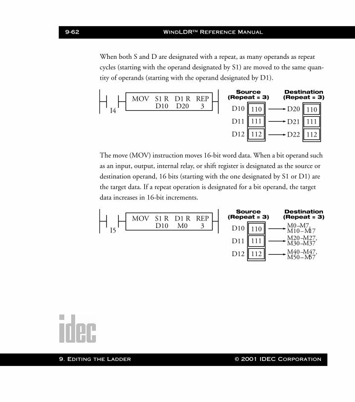
9-62 WindLDR™ Reference Manual
9. Editing t
WLDR ReferenceBook Page 62 Thursday, April 5, 2001 3:36 PM
When both S and D are designated with a repeat, as many operands as repeat
cycles (starting with the operand designated by S1) are moved to the same quan-
tity of operands (starting with the operand designated by D1).
The move (MOV) instruction moves 16-bit word data. When a bit operand such
as an input, output, internal relay, or shift register is designated as the source or
destination operand, 16 bits (starting with the one designated by S1 or D1) are
the target data. If a repeat operation is designated for a bit operand, the target
data increases in 16-bit increments.
I4
MOV S1 R D1 R REPD10 D20 3
112
D10
D11
D12
110
111
112
D20
D21
D22
110
111
Source(Repeat = 3)
Destination(Repeat = 3)
I5
MOV S1 R D1 R REPD10 M0 3
112
D10
D11
D12
110
111
M0–M7,
Source(Repeat = 3)
Destination(Repeat = 3)
M10–M17M20–M27, M30–M37M40–M47, M50–M57
he Ladder © 2001 IDEC Corporation
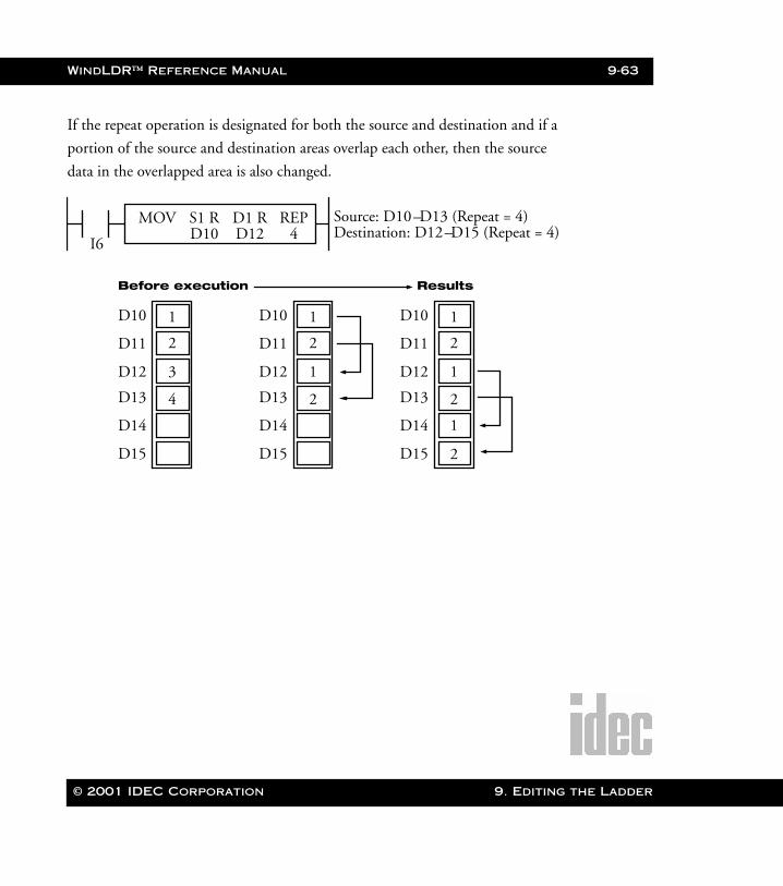
WindLDR™ Reference Manual 9-63
WLDR ReferenceBook Page 63 Thursday, April 5, 2001 3:36 PM
If the repeat operation is designated for both the source and destination and if a
portion of the source and destination areas overlap each other, then the source
data in the overlapped area is also changed.
I6
MOV S1 R D1 R REPD10 D12 4
3
D10
D11
D12
1
2
Before execution
Source: D10–D13 (Repeat = 4)Destination: D12–D15 (Repeat = 4)
4D13
D14
D15
1
D10
D11
D12
1
2
2D13
D14
D15
1
D10
D11
D12
1
2
2
2
1
D13
D14
D15
Results
© 2001 IDEC Corporation 9. Editing the Ladder
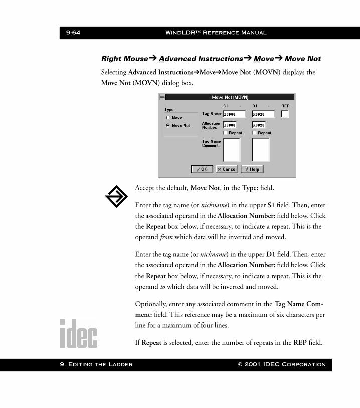
9-64 WindLDR™ Reference Manual
9. Editing t
WLDR ReferenceBook Page 64 Thursday, April 5, 2001 3:36 PM
Right Mouse➔ Advanced Instructions➔ Move➔ Move Not
Selecting Advanced Instructions➔Move➔Move Not (MOVN) displays the
Move Not (MOVN) dialog box.
Accept the default, Move Not, in the Type: field.
Enter the tag name (or nickname) in the upper S1 field. Then, enter
the associated operand in the Allocation Number: field below. Click
the Repeat box below, if necessary, to indicate a repeat. This is the
operand from which data will be inverted and moved.
Enter the tag name (or nickname) in the upper D1 field. Then, enter
the associated operand in the Allocation Number: field below. Click
the Repeat box below, if necessary, to indicate a repeat. This is the
operand to which data will be inverted and moved.
Optionally, enter any associated comment in the Tag Name Com-
ment: field. This reference may be a maximum of six characters per
line for a maximum of four lines.
If Repeat is selected, enter the number of repeats in the REP field.
he Ladder © 2001 IDEC Corporation

WindLDR™ Reference Manual 9-65
WLDR ReferenceBook Page 65 Thursday, April 5, 2001 3:36 PM
Once the dialog box is complete, click the OK button to display the
MOVN instruction on your ladder. To back out of this instruction
without utilizing the MOVN instruction, click the Cancel button.
To access on-line help, click the Help button.
NOTE: The right mouse button is context-sensitive to the specific PLC selected. This
chapter is written in reference to the Micro3 PLC. To access the right mouse
button instructions for another PLC, select the Configure ➔ PLC Selection
option.
Operands Possible (Standard Processing Mode)
Operand S1 (Source 1) D1 (Destination 1)
I 0 – 35 —
Q 0 – 31 0 – 31
M 0 – 317 0 – 287
T 0 – 31 0 – 31
C 0 – 31 0 – 31
R 0 – 63 0 – 63
D (Micro3) 0 – 99 0 – 99
MOVN S1(R) D1(R) REP***** **** **
S1 NOT➔D1
When an input is on, 16-bit word data from the operand designated by S1 is inverted bit by bit and moved to theoperand designated by D1.
© 2001 IDEC Corporation 9. Editing the Ladder
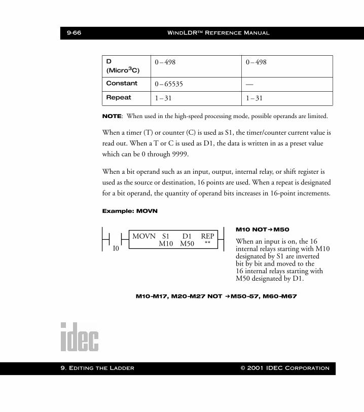
9-66 WindLDR™ Reference Manual
9. Editing t
WLDR ReferenceBook Page 66 Thursday, April 5, 2001 3:36 PM
NOTE: When used in the high-speed processing mode, possible operands are limited.
When a timer (T) or counter (C) is used as S1, the timer/counter current value is
read out. When a T or C is used as D1, the data is written in as a preset value
which can be 0 through 9999.
When a bit operand such as an input, output, internal relay, or shift register is
used as the source or destination, 16 points are used. When a repeat is designated
for a bit operand, the quantity of operand bits increases in 16-point increments.
Example: MOVN
D (Micro3C)
0 – 498 0 – 498
Constant 0 – 65535 —
Repeat 1 – 31 1 – 31
I0
MOVN S1 D1 REPM10 M50 **
M10 NOT➔M50
When an input is on, the 16 internal relays starting with M10designated by S1 are inverted bit by bit and moved to the16 internal relays starting with M50 designated by D1.
M10–M17, M20–M27 NOT ➔M50–57, M60–M67
he Ladder © 2001 IDEC Corporation

WindLDR™ Reference Manual 9-67
WLDR ReferenceBook Page 67 Thursday, April 5, 2001 3:36 PM
The on/off statuses of the 16 internal relays, M10–M17 and M20–M27, are
inverted and moved to 16 internal relays, M50–M57 and M60–M67. When
M50 and M60 are monitored on the program loader, the data is displayed as
shown on the right below. M50 is the least significant bit (LSB), and M67 is the
most significant bit (MSB).
I1
MOVN S1 D1 REP810 D2 **
810 NOT ➔ D2
When input I1 is on, constant 810 designated by S1 is invertedbit by bit and moved to data
Before inversion (M17–M0):
After inversion (M67–M50):
MSB S1 LSB
0 0 1 1 0 0 0 0 0 0 1 1 1 0 0 1
MSB D1 LSB
1 1 0 0 1 1 1 1 1 1 0 0 0 1 1 0
register D2 designated by D1.
© 2001 IDEC Corporation 9. Editing the Ladder
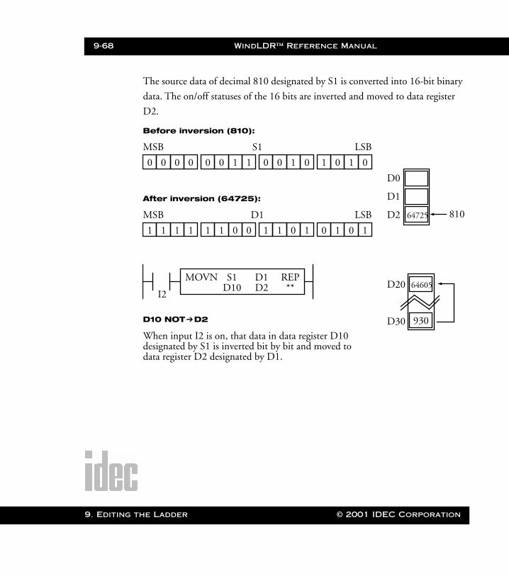
9-68 WindLDR™ Reference Manual
9. Editing t
WLDR ReferenceBook Page 68 Thursday, April 5, 2001 3:36 PM
The source data of decimal 810 designated by S1 is converted into 16-bit binary
data. The on/off statuses of the 16 bits are inverted and moved to data register
D2.
I2
MOVN S1 D1 REPD10 D2 **
D10 NOT➔D2
When input I2 is on, that data in data register D10
Before inversion (810):
After inversion (64725):
MSB S1 LSB
0 0 0 0 0 0 1 1 0 0 1 0 1 0 1 0
MSB D1 LSB
1 1 1 1 1 1 0 0 1 1 0 1 0 1 0 1
64725
D0
D1
D2 810
64605D20
D30 930
designated by S1 is inverted bit by bit and moved to data register D2 designated by D1.
he Ladder © 2001 IDEC Corporation

WindLDR™ Reference Manual 9-69
WLDR ReferenceBook Page 69 Thursday, April 5, 2001 3:36 PM
Right Mouse➔ Advanced Instructions➔ Move➔Indirect Move (IMOV)
Selecting Advanced Instructions➔Move➔Indirect Move (IMOV) displays the
Indirect Move (IMOV) dialog box.
You may also click the toolbar button:
Accept the default, Indirect Move, in the Type: field.
Enter the tag name (or nickname) in the upper S1 field. Then, enter
the associated operand in the allocation number field below. Click
the Repeat box below, if necessary, to indicate a repeat. This is the
first operand from which data will be moved.
Enter the tag name (or nickname) in the upper S2 field. Then, enter
the associated operand in the allocation number field below. This is
the amount of the offset from which data will be moved.
© 2001 IDEC Corporation 9. Editing the Ladder

9-70 WindLDR™ Reference Manual
9. Editing t
WLDR ReferenceBook Page 70 Thursday, April 5, 2001 3:36 PM
Enter the tag name (or nickname) in the upper D1 field. Then, enter
the associated operand in the allocation number field below. Click
the Repeat box below, if necessary, to indicate a repeat. This is the
first operand to which data will be moved.
Enter the tag name (or nickname) in the upper D2 field. Then, enter
the associated operand in the allocation number field below. This is
the amount of the offset to which data will be moved.
Optionally, enter any associated comment in the tag name comment
field. This reference may be a maximum of six characters per line for
a maximum of four lines.
If Repeat is selected, enter the number of repeats in the REP field.
Once the dialog box is complete, click the OK button to display the
IMOV instruction on your ladder. To back out of this instruction
without utilizing the IMOV instruction, click the Cancel button.
To access on-line help, click the Help button.
NOTE: The right mouse button is context-sensitive to the specific PLC selected. This
chapter is written in reference to the Micro3 PLC. To access the right mouse
button instructions for another PLC, select the Configure ➔ PLC Selection
option.
he Ladder © 2001 IDEC Corporation
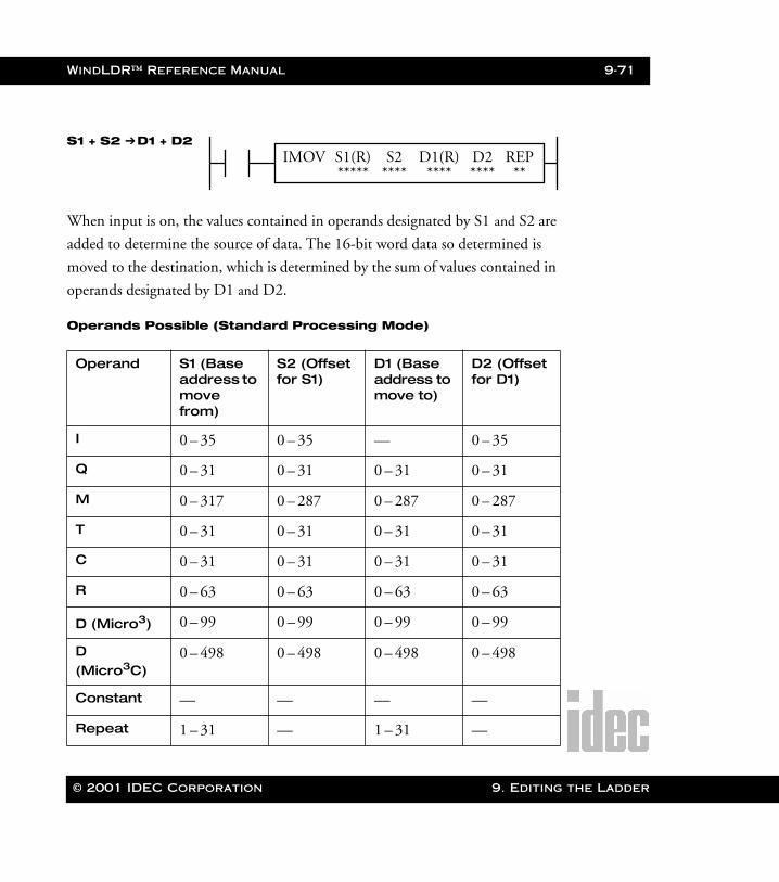
WindLDR™ Reference Manual 9-71
WLDR ReferenceBook Page 71 Thursday, April 5, 2001 3:36 PM
When input is on, the values contained in operands designated by S1 and S2 are
added to determine the source of data. The 16-bit word data so determined is
moved to the destination, which is determined by the sum of values contained in
operands designated by D1 and D2.
Operands Possible (Standard Processing Mode)
Operand S1 (Base address to move from)
S2 (Offset for S1)
D1 (Base address to move to)
D2 (Offset for D1)
I 0 – 35 0 – 35 — 0 – 35
Q 0 – 31 0 – 31 0 – 31 0 – 31
M 0 – 317 0 – 287 0 – 287 0 – 287
T 0 – 31 0 – 31 0 – 31 0 – 31
C 0 – 31 0 – 31 0 – 31 0 – 31
R 0 – 63 0 – 63 0 – 63 0 – 63
D (Micro3) 0 – 99 0 – 99 0 – 99 0 – 99
D (Micro3C)
0 – 498 0 – 498 0 – 498 0 – 498
Constant — — — —
Repeat 1 – 31 — 1 – 31 —
IMOV S1(R) D1(R) REP***** **** **
S1 + S2 ➔D1 + D2D2****
S2****
© 2001 IDEC Corporation 9. Editing the Ladder
9-72 WindLDR™ Reference Manual
9. Editing t
WLDR ReferenceBook Page 72 Thursday, April 5, 2001 3:36 PM
NOTE: When used in the high-speed processing mode, possible operands are limited.
When timer (T) or counter (C) is designated as S1, S2, or D2, the operand data
is the current value of the timer/counter. When T or C is designated as D1, the
operand data is the timer/counter preset value which can be 0 through 9999.
Make sure that the source data determined by S1 + S2 and the destination data
determined by D1 + D2 are within the operand range. If the derived source or
destination operand is out of the operand range, a user program execution error
will result, turning special internal relay M304 and error indicator ERR1 on.
When a bit operand such as an input, output, internal relay, or shift register is
used as the source or destination, 16 points are used. When a repeat is designated
for a bit operand, the quantity of operand bits increases in 16-point increments.
Source operand S2 and destination operand D2 do not have to be designated. If
S2 or D2 is not designated, the source or destination operand is determined by
S1 or D1 without offset.
he Ladder © 2001 IDEC Corporation

WindLDR™ Reference Manual 9-73
WLDR ReferenceBook Page 73 Thursday, April 5, 2001 3:36 PM
Example: IMOV
D20 + C10 ➔ D10 + D25
Source operand S1 and destination operand D1 determine
the type of operand. Source operand S2 and destination
operand D2 are the offset values to determine the source
and destination operands.
If the current value of counter C10 designated by source
operand S2 is 4, then the data is determined by adding the
offset to data register D20 designated by source operand S1:
D(20 + 4) = D24
If data register D25 contains a value of 20, then the destina-
tion is determined by adding the offset to data register D10
designated by destination operand D1:
D(10 + 20) = D30
As a result, when input I0 is on, the data in data register D24
is moved to data register D30.
I1
IMOV S1 D1 REPD20 D10 **
D2D25
S2C10
20
D20
D21
D22
D30 6450
6450
D23
D24
D25
4C10
© 2001 IDEC Corporation 9. Editing the Ladder
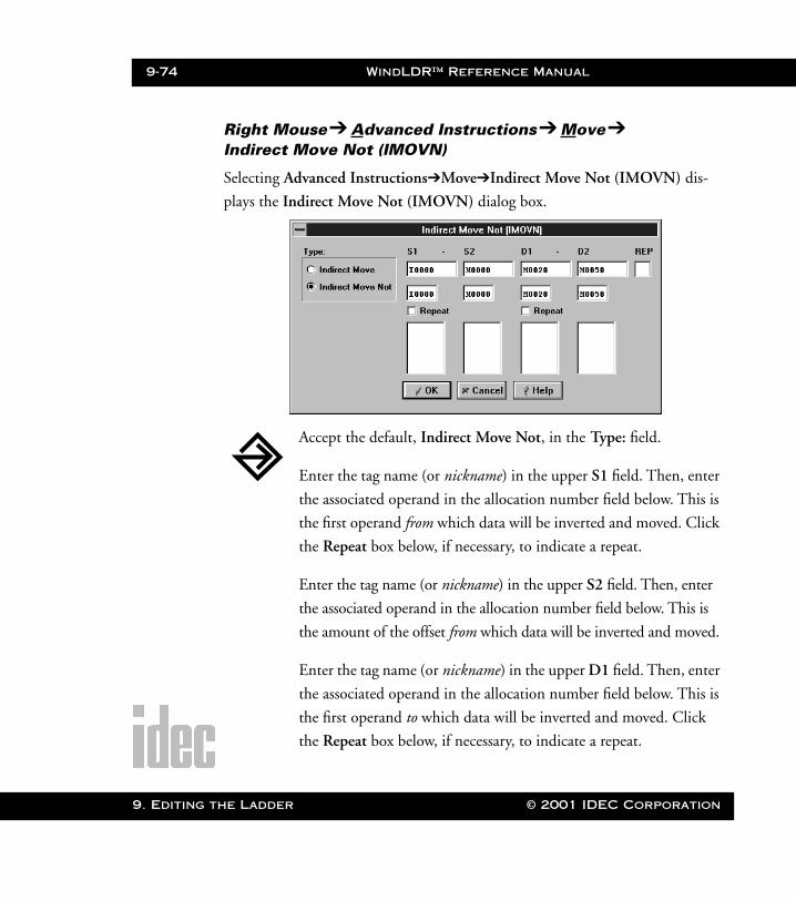
9-74 WindLDR™ Reference Manual
9. Editing t
WLDR ReferenceBook Page 74 Thursday, April 5, 2001 3:36 PM
Right Mouse➔ Advanced Instructions➔ Move➔Indirect Move Not (IMOVN)
Selecting Advanced Instructions➔Move➔Indirect Move Not (IMOVN) dis-
plays the Indirect Move Not (IMOVN) dialog box.
Accept the default, Indirect Move Not, in the Type: field.
Enter the tag name (or nickname) in the upper S1 field. Then, enter
the associated operand in the allocation number field below. This is
the first operand from which data will be inverted and moved. Click
the Repeat box below, if necessary, to indicate a repeat.
Enter the tag name (or nickname) in the upper S2 field. Then, enter
the associated operand in the allocation number field below. This is
the amount of the offset from which data will be inverted and moved.
Enter the tag name (or nickname) in the upper D1 field. Then, enter
the associated operand in the allocation number field below. This is
the first operand to which data will be inverted and moved. Click
the Repeat box below, if necessary, to indicate a repeat.
he Ladder © 2001 IDEC Corporation

WindLDR™ Reference Manual 9-75
WLDR ReferenceBook Page 75 Thursday, April 5, 2001 3:36 PM
Enter the tag name (or nickname) in the upper D2 field. Then, enter
the associated operand in the allocation number field below. This is
the amount of the offset to which data will be inverted and moved.
Optionally, enter any associated comment in the tag name comment
field. This reference may be a maximum of six characters per line for
a maximum of four lines.
If Repeat is selected, enter the number of repeats in the REP field.
Once the dialog box is complete, click the OK button to display the
IMOVN instruction on your ladder. To back out of this instruction
without utilizing the IMOVN instruction, click the Cancel button.
To access on-line help, click the Help button.
NOTE: The right mouse button is context-sensitive to the specific PLC selected. This
chapter is written in reference to the Micro3 PLC. To access the right mouse
button instructions for another PLC, select the Configure ➔ PLC Selection
option.
IMOVN S1(R) D1(R) REP***** **** **
S1 + S2 NOT ➔D2****
S2****
When an input is on, the values contained in operands designated by S1 and S2
are added to determine the source of data. The 16-bit word data so determined is
inverted and moved to the destination, which is determined by the sum of values
contained in operands designated by D1 and D2.
D1 + D2
© 2001 IDEC Corporation 9. Editing the Ladder
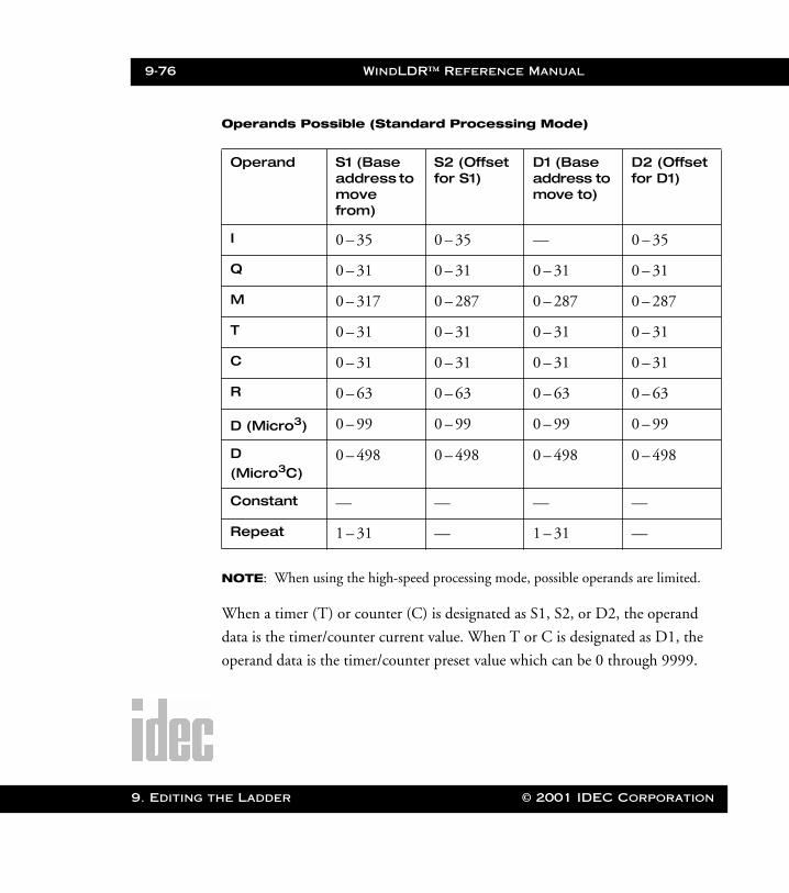
9-76 WindLDR™ Reference Manual
9. Editing t
WLDR ReferenceBook Page 76 Thursday, April 5, 2001 3:36 PM
Operands Possible (Standard Processing Mode)
NOTE: When using the high-speed processing mode, possible operands are limited.
When a timer (T) or counter (C) is designated as S1, S2, or D2, the operand
data is the timer/counter current value. When T or C is designated as D1, the
operand data is the timer/counter preset value which can be 0 through 9999.
Operand S1 (Base address to move from)
S2 (Offset for S1)
D1 (Base address to move to)
D2 (Offset for D1)
I 0 – 35 0 – 35 — 0 – 35
Q 0 – 31 0 – 31 0 – 31 0 – 31
M 0 – 317 0 – 287 0 – 287 0 – 287
T 0 – 31 0 – 31 0 – 31 0 – 31
C 0 – 31 0 – 31 0 – 31 0 – 31
R 0 – 63 0 – 63 0 – 63 0 – 63
D (Micro3) 0 – 99 0 – 99 0 – 99 0 – 99
D (Micro3C)
0 – 498 0 – 498 0 – 498 0 – 498
Constant — — — —
Repeat 1 – 31 — 1 – 31 —
he Ladder © 2001 IDEC Corporation
WindLDR™ Reference Manual 9-77
WLDR ReferenceBook Page 77 Thursday, April 5, 2001 3:36 PM
Make sure that the source data determined by S1 + S2 and the destination data
determined by D1 + D2 are within the operand range. If the derived source or
destination operand is out of the operand range, a user program execution error
will result, turning special internal relay M304 and error indicator ERR1 on.
When a bit operand such as an input, output, internal relay, or shift register is
used as the source or destination, 16 points are used. When a repeat is designated
for a bit operand, the quantity of operand bits increases in 16-point increments.
Do not designate both source operand S2 and destination operand D2. (An error
occurs if both are designated.) If S2 or D2 is not designated, then the source or
destination operand is determined by S1 or D1 without an offset.
© 2001 IDEC Corporation 9. Editing the Ladder
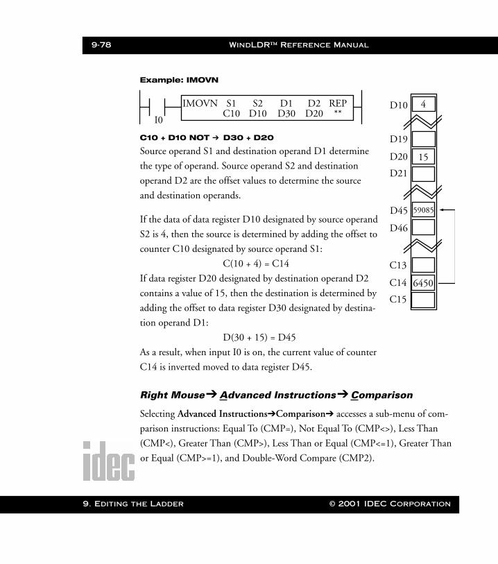
9-78 WindLDR™ Reference Manual
9. Editing t
WLDR ReferenceBook Page 78 Thursday, April 5, 2001 3:36 PM
Example: IMOVN
Right Mouse➔ Advanced Instructions➔ Comparison
Selecting Advanced Instructions➔Comparison➔ accesses a sub-menu of com-
parison instructions: Equal To (CMP=), Not Equal To (CMP<>), Less Than
(CMP<), Greater Than (CMP>), Less Than or Equal (CMP<=1), Greater Than
or Equal (CMP>=1), and Double-Word Compare (CMP2).
C10 + D10 NOT ➔ D30 + D20
Source operand S1 and destination operand D1 determine
the type of operand. Source operand S2 and destination
operand D2 are the offset values to determine the source
and destination operands.
If the data of data register D10 designated by source operand
S2 is 4, then the source is determined by adding the offset to
counter C10 designated by source operand S1:
C(10 + 4) = C14
If data register D20 designated by destination operand D2
contains a value of 15, then the destination is determined by
adding the offset to data register D30 designated by destina-
tion operand D1:
D(30 + 15) = D45
As a result, when input I0 is on, the current value of counter
C14 is inverted moved to data register D45.
I0
IMOVN S1 D1 REPC10 D30 **
D2D20
S2D10
D10
D19
D46
D20
D21
4
15
D45 59085
C13
C14
C15
6450
he Ladder © 2001 IDEC Corporation
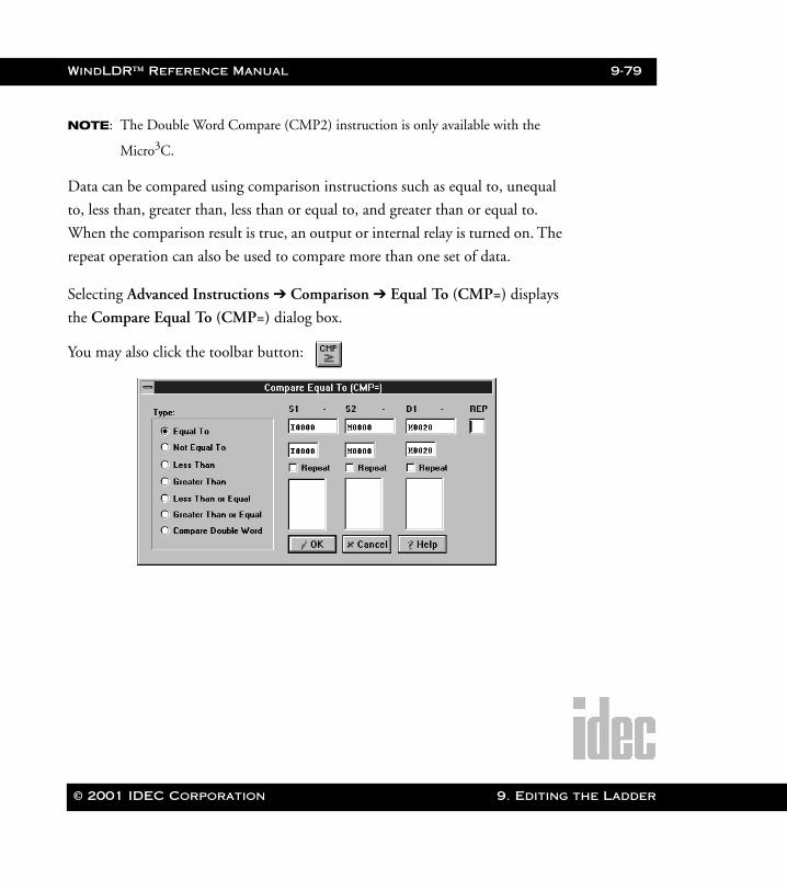
WindLDR™ Reference Manual 9-79
WLDR ReferenceBook Page 79 Thursday, April 5, 2001 3:36 PM
NOTE: The Double Word Compare (CMP2) instruction is only available with the
Micro3C.
Data can be compared using comparison instructions such as equal to, unequal
to, less than, greater than, less than or equal to, and greater than or equal to.
When the comparison result is true, an output or internal relay is turned on. The
repeat operation can also be used to compare more than one set of data.
Selecting Advanced Instructions ➔ Comparison ➔ Equal To (CMP=) displays
the Compare Equal To (CMP=) dialog box.
You may also click the toolbar button:
© 2001 IDEC Corporation 9. Editing the Ladder
9-80 WindLDR™ Reference Manual
9. Editing t
WLDR ReferenceBook Page 80 Thursday, April 5, 2001 3:36 PM
In the Type: field, click the circle of the appropriate selection.
Enter the tag name (or nickname) in the upper S1 field. Then, enter
the associated operand in the allocation number field below. Click
the Repeat box below, if necessary, to indicate a repeat.
Enter the tag name (or nickname) in the upper S2 field. Then, enter
the associated operand in the allocation number field below. Click
the Repeat box below, if necessary, to indicate a repeat.
The data in S2 is compared against the data in S1.
Enter the tag name (or nickname) in the upper D1 field. Then, enter
the associated operand in the allocation number field below. Click
the Repeat box below, if necessary, to indicate a repeat. If the
selected condition is true, then this operand will turn on. If the
selected condition is not true, then the operand will turn off.
Optionally, enter any associated comment in the lower tag name
comment field. This reference may be a maximum of six characters
per line for a maximum of four lines.
If Repeat is selected, enter the number of repeats in the REP field.
Once the dialog box is complete, click the OK button to display the
CMP instruction on your ladder. To back out of this instruction
without utilizing the CMP instruction, click the Cancel button.
To access on-line help, click the Help button.
he Ladder © 2001 IDEC Corporation
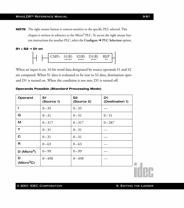
WindLDR™ Reference Manual 9-81
WLDR ReferenceBook Page 81 Thursday, April 5, 2001 3:36 PM
NOTE: The right mouse button is context-sensitive to the specific PLC selected. This
chapter is written in reference to the Micro3 PLC. To access the right mouse but-
ton instructions for another PLC, select the Configure ➔ PLC Selection option.
S1 = S2 ➔ D1 on
When an input is on, 16-bit word data designated by source operands S1 and S2
are compared. When S1 data is evaluated to be true to S2 data, destination oper-
and D1 is turned on. When the condition is not met, D1 is turned off.
Operands Possible (Standard Processing Mode)
Operand S1 (Source 1)
S2 (Source 2)
D1 (Destination 1)
I 0 – 35 0 – 35 —
Q 0 – 31 0 – 31 0 – 31
M 0 – 317 0 – 317 0 – 287
T 0 – 31 0 – 31 —
C 0 – 31 0 – 31 —
R 0 – 63 0 – 63 —
D (Micro3) 0 – 99 0 – 99 —
D (Micro3C)
0 – 498 0 – 498 —
CMP= S1(R) D1(R) REP***** **** **
S2(R)****
© 2001 IDEC Corporation 9. Editing the Ladder

9-82 WindLDR™ Reference Manual
9. Editing t
WLDR ReferenceBook Page 82 Thursday, April 5, 2001 3:36 PM
When timer (T) or counter (C) is designated as S1 or S2, the current value of the
timer/counter is read out.
Maintaining the Comparison Output
If the input to the comparison instruction is off, then the comparison output is
maintained. If the comparison output is on, then the on status is maintained
when the input is turned off. The following examples show how the programs
maintain or clear the output when the input is turned off.
Examples: CMP>=
This program maintains the comparison output status when the input is off.
Constant 0 – 65535 0 – 65535 —
Repeat 1 – 31 1 – 31 1 – 31
I0
CMP>= S1 D1 REPD10 Q0 **
S2C10
Input I0 ONOFF
Comparison Result D10 ≤ C1D10 < C1
Comparison Output Q0 ONOFF
he Ladder © 2001 IDEC Corporation
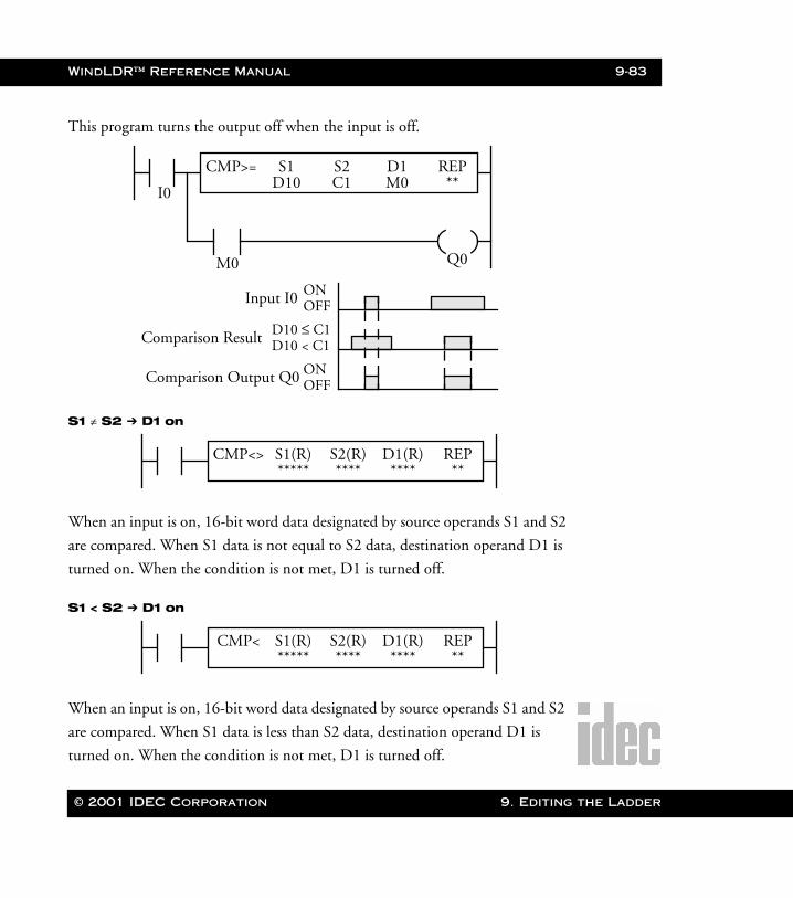
WindLDR™ Reference Manual 9-83
WLDR ReferenceBook Page 83 Thursday, April 5, 2001 3:36 PM
This program turns the output off when the input is off.
S1 ≠ S2 ➔ D1 on
When an input is on, 16-bit word data designated by source operands S1 and S2
are compared. When S1 data is not equal to S2 data, destination operand D1 is
turned on. When the condition is not met, D1 is turned off.
S1 < S2 ➔ D1 on
When an input is on, 16-bit word data designated by source operands S1 and S2
are compared. When S1 data is less than S2 data, destination operand D1 is
turned on. When the condition is not met, D1 is turned off.
I0
CMP>= S1 D1 REPD10 M0 **
S2C1
Input I0 ONOFF
Comparison Result D10 ≤ C1D10 < C1
Comparison Output Q0 ONOFF
Q0M0
CMP<> S1(R) D1(R) REP***** **** **
S2(R)****
CMP< S1(R) D1(R) REP***** **** **
S2(R)****
© 2001 IDEC Corporation 9. Editing the Ladder
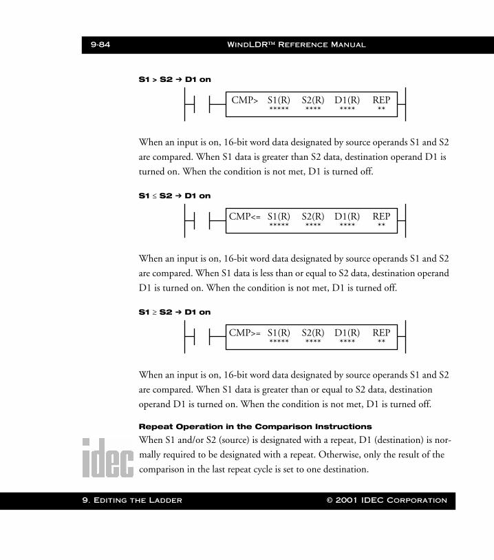
9-84 WindLDR™ Reference Manual
9. Editing t
WLDR ReferenceBook Page 84 Thursday, April 5, 2001 3:36 PM
S1 > S2 ➔ D1 on
When an input is on, 16-bit word data designated by source operands S1 and S2
are compared. When S1 data is greater than S2 data, destination operand D1 is
turned on. When the condition is not met, D1 is turned off.
S1 ≤ S2 ➔ D1 on
When an input is on, 16-bit word data designated by source operands S1 and S2
are compared. When S1 data is less than or equal to S2 data, destination operand
D1 is turned on. When the condition is not met, D1 is turned off.
S1 ≥ S2 ➔ D1 on
When an input is on, 16-bit word data designated by source operands S1 and S2
are compared. When S1 data is greater than or equal to S2 data, destination
operand D1 is turned on. When the condition is not met, D1 is turned off.
Repeat Operation in the Comparison Instructions
When S1 and/or S2 (source) is designated with a repeat, D1 (destination) is nor-
mally required to be designated with a repeat. Otherwise, only the result of the
comparison in the last repeat cycle is set to one destination.
CMP> S1(R) D1(R) REP***** **** **
S2(R)****
CMP<= S1(R) D1(R) REP***** **** **
S2(R)****
CMP>= S1(R) D1(R) REP***** **** **
S2(R)****
he Ladder © 2001 IDEC Corporation
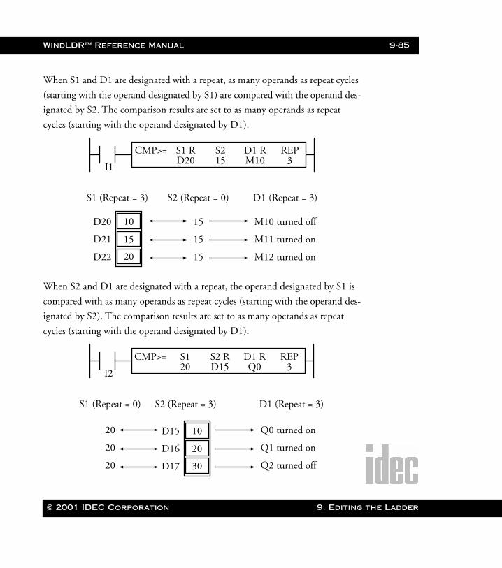
WindLDR™ Reference Manual 9-85
WLDR ReferenceBook Page 85 Thursday, April 5, 2001 3:36 PM
When S1 and D1 are designated with a repeat, as many operands as repeat cycles
(starting with the operand designated by S1) are compared with the operand des-
ignated by S2. The comparison results are set to as many operands as repeat
cycles (starting with the operand designated by D1).
When S2 and D1 are designated with a repeat, the operand designated by S1 is
compared with as many operands as repeat cycles (starting with the operand des-
ignated by S2). The comparison results are set to as many operands as repeat
cycles (starting with the operand designated by D1).
I1
CMP>= S1 R D1 R REPD20 M10 3
S215
D20 10
D21
D22
15
20
S1 (Repeat = 3) S2 (Repeat = 0) D1 (Repeat = 3)
15
15
15
M10 turned off
M11 turned on
M12 turned on
I2
CMP>= S1 D1 R REP20 Q0 3
S2 RD15
D15 10
D16
D17
20
30
S1 (Repeat = 0) S2 (Repeat = 3) D1 (Repeat = 3)
20
20
20
Q0 turned on
Q1 turned on
Q2 turned off
© 2001 IDEC Corporation 9. Editing the Ladder
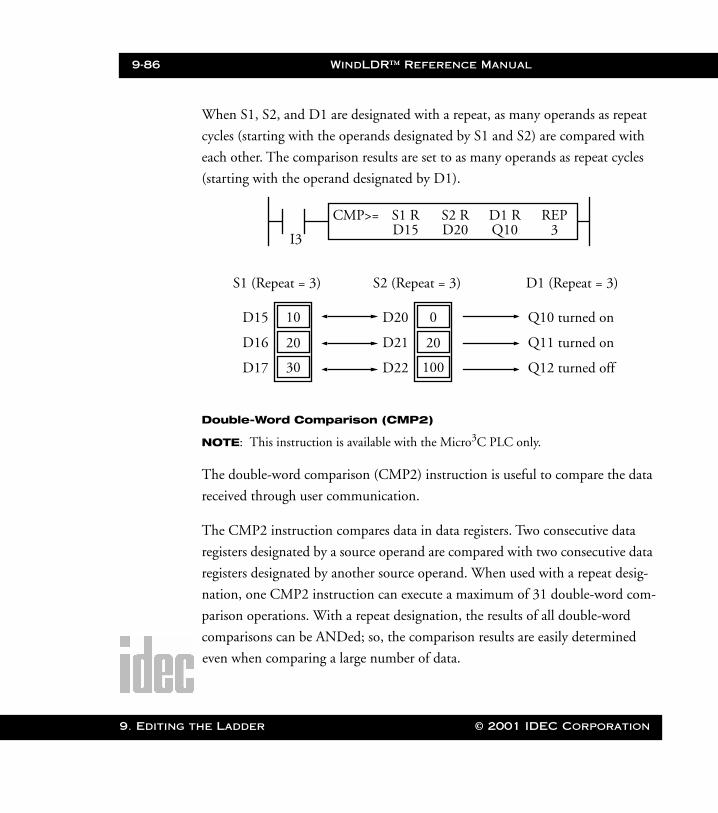
9-86 WindLDR™ Reference Manual
9. Editing t
WLDR ReferenceBook Page 86 Thursday, April 5, 2001 3:36 PM
When S1, S2, and D1 are designated with a repeat, as many operands as repeat
cycles (starting with the operands designated by S1 and S2) are compared with
each other. The comparison results are set to as many operands as repeat cycles
(starting with the operand designated by D1).
Double-Word Comparison (CMP2)
NOTE: This instruction is available with the Micro3C PLC only.
The double-word comparison (CMP2) instruction is useful to compare the data
received through user communication.
The CMP2 instruction compares data in data registers. Two consecutive data
registers designated by a source operand are compared with two consecutive data
registers designated by another source operand. When used with a repeat desig-
nation, one CMP2 instruction can execute a maximum of 31 double-word com-
parison operations. With a repeat designation, the results of all double-word
comparisons can be ANDed; so, the comparison results are easily determined
even when comparing a large number of data.
I3
CMP>= S1 R D1 R REPD15 Q10 3
S2 RD20
D15 10
D16
D17
20
30
S1 (Repeat = 3) D1 (Repeat = 3)
Q10 turned on
Q11 turned on
Q12 turned off
D20 0
D21
D22
20
100
S2 (Repeat = 3)
he Ladder © 2001 IDEC Corporation
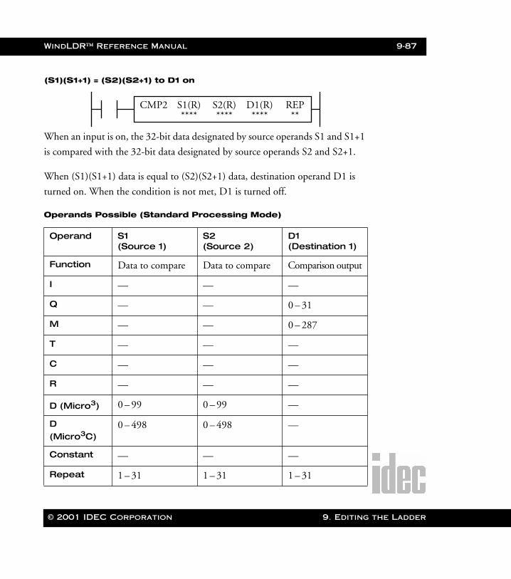
WindLDR™ Reference Manual 9-87
WLDR ReferenceBook Page 87 Thursday, April 5, 2001 3:36 PM
(S1)(S1+1) = (S2)(S2+1) to D1 on
When an input is on, the 32-bit data designated by source operands S1 and S1+1
is compared with the 32-bit data designated by source operands S2 and S2+1.
When (S1)(S1+1) data is equal to (S2)(S2+1) data, destination operand D1 is
turned on. When the condition is not met, D1 is turned off.
Operands Possible (Standard Processing Mode)
Operand S1 (Source 1)
S2 (Source 2)
D1 (Destination 1)
Function Data to compare Data to compare Comparison output
I — — —
Q — — 0 – 31
M — — 0 – 287
T — — —
C — — —
R — — —
D (Micro3) 0 – 99 0 – 99 —
D (Micro3C)
0 – 498 0 – 498 —
Constant — — —
Repeat 1 – 31 1 – 31 1 – 31
CMP2 S1(R) D1(R) REP**** **** **
S2(R)****
© 2001 IDEC Corporation 9. Editing the Ladder
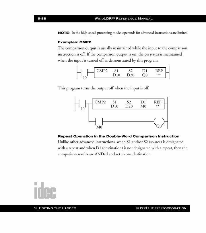
9-88 WindLDR™ Reference Manual
9. Editing t
WLDR ReferenceBook Page 88 Thursday, April 5, 2001 3:36 PM
NOTE: In the high-speed processing mode, operands for advanced instructions are limited.
Examples: CMP2
The comparison output is usually maintained while the input to the comparison
instruction is off. If the comparison output is on, the on status is maintained
when the input is turned off as demonstrated by this program.
This program turns the output off when the input is off.
Repeat Operation in the Double-Word Comparison Instruction
Unlike other advanced instructions, when S1 and/or S2 (source) is designated
with a repeat and when D1 (destination) is not designated with a repeat, then the
comparison results are ANDed and set to one destination.
I0
CMP2 S1 D1 REPD10 Q0 **
S2D20
I0
CMP2 S1 D1 REPD10 M0 **
S2D20
Q0M0
he Ladder © 2001 IDEC Corporation

WindLDR™ Reference Manual 9-89
WLDR ReferenceBook Page 89 Thursday, April 5, 2001 3:36 PM
When only S1 (source) is designated with a repeat, as many double-word oper-
ands as repeat cycles (starting with the operand designated by S1) are compared
with the double-word operand designated by S2. The comparison results are
ANDed and set to the operand designated by D1.
When only S2 (source) is designated with a repeat, the double-word operand
designated by S1 is compared with as many double-word operands as repeat
cycles, starting with the operand designated by S2. The comparison results are
ANDed and set to the operand designated by D1.
I1
CMP2 S1 R D1 REPD20 M50 3
S2D30
D20–D21
D22–D23
D24–D25
S1 (Repeat = 3) D1 (Repeat = 0)
M50
D30–D31
D30–D31
D30–D31
S2 (Repeat = 0)
AND
I2
CMP2 S1 D1 REPD20 M50 3
S2 RD30
D20–D21
D20–D21
D20–D21
S1 (Repeat = 0) D1 (Repeat = 0)
M50
D30–D31
D32–D33
D34–D35
S2 (Repeat = 3)
AND
© 2001 IDEC Corporation 9. Editing the Ladder
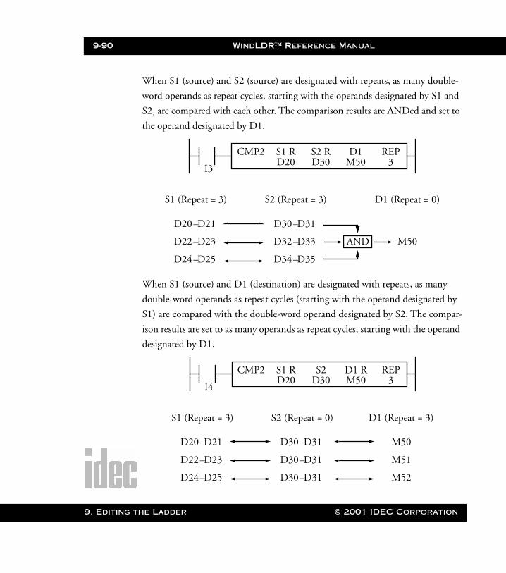
9-90 WindLDR™ Reference Manual
9. Editing t
WLDR ReferenceBook Page 90 Thursday, April 5, 2001 3:36 PM
When S1 (source) and S2 (source) are designated with repeats, as many double-
word operands as repeat cycles, starting with the operands designated by S1 and
S2, are compared with each other. The comparison results are ANDed and set to
the operand designated by D1.
When S1 (source) and D1 (destination) are designated with repeats, as many
double-word operands as repeat cycles (starting with the operand designated by
S1) are compared with the double-word operand designated by S2. The compar-
ison results are set to as many operands as repeat cycles, starting with the operand
designated by D1.
I3
CMP2 S1 R D1 REPD20 M50 3
S2 RD30
D20–D21
D22–D23
D24–D25
S1 (Repeat = 3) D1 (Repeat = 0)
M50
D30–D31
D32–D33
D34–D35
S2 (Repeat = 3)
AND
I4
CMP2 S1 R D1 R REPD20 M50 3
S2D30
D20–D21
D22–D23
D24–D25
S1 (Repeat = 3)
D30–D31
D30–D31
D30–D31
S2 (Repeat = 0)
M50
M51
M52
D1 (Repeat = 3)
he Ladder © 2001 IDEC Corporation

WindLDR™ Reference Manual 9-91
WLDR ReferenceBook Page 91 Thursday, April 5, 2001 3:36 PM
When S2 (source) and D1 (destination) are designated with repeats, the double-
word operand designated by S1 is compared with as many double-word operands
as repeat cycles, starting with the operand designated by S2. The comparison
results are set to as many operands as repeat cycles, starting with the operand des-
ignated by D1.
When S1, S2 (source), and D1 (destination) are designated with repeat, double-
word operands as many as the repeat cycles (starting with the operands desig-
nated by S1 and S2) are compared with each other. The comparison results are
set to operands as many as the repeat cycles starting with the operand designated
by D1.
I5
CMP2 S1 D1 R REPD20 M50 3
S2 RD30
D20–D21
D20–D21
D20–D21
S1 (Repeat = 0)
D30–D31
D32–D33
D34–D35
S2 (Repeat = 3)
M50
M51
M52
D1 (Repeat = 3)
I6
CMP2 S1 R D1 R REPD20 M50 3
S2 RD30
D20–D21
D22–D23
D24–D25
S1 (Repeat = 3)
D30–D31
D32–D33
D34–D35
S2 (Repeat = 3)
M50
M51
M52
D1 (Repeat = 3)
© 2001 IDEC Corporation 9. Editing the Ladder
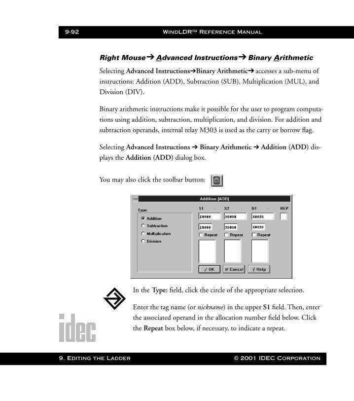
9-92 WindLDR™ Reference Manual
9. Editing t
WLDR ReferenceBook Page 92 Thursday, April 5, 2001 3:36 PM
Right Mouse➔ Advanced Instructions➔ Binary Arithmetic
Selecting Advanced Instructions➔Binary Arithmetic➔ accesses a sub-menu of
instructions: Addition (ADD), Subtraction (SUB), Multiplication (MUL), and
Division (DIV).
Binary arithmetic instructions make it possible for the user to program computa-
tions using addition, subtraction, multiplication, and division. For addition and
subtraction operands, internal relay M303 is used as the carry or borrow flag.
Selecting Advanced Instructions ➔ Binary Arithmetic ➔ Addition (ADD) dis-
plays the Addition (ADD) dialog box.
You may also click the toolbar button:
In the Type: field, click the circle of the appropriate selection.
Enter the tag name (or nickname) in the upper S1 field. Then, enter
the associated operand in the allocation number field below. Click
the Repeat box below, if necessary, to indicate a repeat.
he Ladder © 2001 IDEC Corporation
WindLDR™ Reference Manual 9-93
WLDR ReferenceBook Page 93 Thursday, April 5, 2001 3:36 PM
Enter the tag name (or nickname) in the upper S2 field. Then, enter
the associated operand in the allocation number field below. Click
the Repeat box below, if necessary, to indicate a repeat.
The data in S1 and S2 is added, subtracted, multiplied, or divided as
specified in the Type: field.
Enter the tag name (or nickname) in the upper D1 field. Then, enter
the associated operand in the allocation number field below. Click
the Repeat box below, if necessary, to indicate a repeat. The result of
the arithmetic is set to operand D1.
Optionally, enter any associated comment in the lower tag name
comment field. This reference may be a maximum of six characters
per line for a maximum of four lines.
If Repeat is selected, enter the number of repeats in the REP field.
Once the dialog box is complete, click the OK button to display the
arithmetic instruction on your ladder. To back out of this instruction
without utilizing the arithmetic instruction, click the Cancel button.
To access on-line help, click the Help button.
NOTE: The right mouse button is context-sensitive to the specific PLC selected. This
chapter is written in reference to the Micro3 PLC. To access the right mouse
button instructions for another PLC, select the Configure ➔ PLC Selection
option.
© 2001 IDEC Corporation 9. Editing the Ladder

9-94 WindLDR™ Reference Manual
9. Editing t
WLDR ReferenceBook Page 94 Thursday, April 5, 2001 3:36 PM
S1 + S2 ➔ D1, CY
When an input is on, 16-bit word data designated by source operands S1 and S2
are added. The result is set to destination operand D1 and carry (M303).
Operands Possible (Standard Processing Mode)
When a timer (T) or counter (C) is used as S1 or S2, the current value of the
timer/counter is read out.
Operand S1 (Source 1)
S2 (Source 2)
D1 (Destination 1)
I 0 – 35 0 – 35 —
Q 0 – 31 0 – 31 0 – 31
M 0 – 317 0 – 317 0 – 287
T 0 – 31 0 – 31 0 – 31
C 0 – 31 0 – 31 0 – 31
R 0 – 63 0 – 63 0 – 63
D (Micro3) 0 – 99 0 – 99 0 – 99
D (Micro3C)
0 – 498 0 – 498 0 – 498
Constant 0 – 65535 0 – 65535 —
Repeat 1 – 31 1 – 31 1 – 31
ADD S1(R) D1(R) REP***** **** **
S2(R)****
he Ladder © 2001 IDEC Corporation
WindLDR™ Reference Manual 9-95
WLDR ReferenceBook Page 95 Thursday, April 5, 2001 3:36 PM
When T or C is used as D1, the data is written in as a preset value which can be
0–9999.
NOTE: When using the timer or counter as a destination, make sure that the data does
not exceed the maximum preset value of 9999. When the preset value exceeds
9999, a user program execution error will result, turning on error indicator
ERR1 and special internal relay M304. When a user program execution error
occurs, the result is not set to the destination.
Since the binary arithmetic instructions are executed in each scan while input is
on, a pulse input from a SOTU or SOTD instruction should be used as required.
Using Carry or Borrow Flags
When the D1 (destination) data exceeds 65535 as a result of addition, a carry
occurs and special internal relay M303 is turned on. When the D1 data is less
than zero as a result of subtraction, a borrow occurs and special internal relay
M303 is turned on.
There are three ways to program the carrying process (see examples below). If a
carry never goes on, then the program does not have to include internal relay
M303 to process carrying. If a carry goes on unexpectedly, then an output can be
programmed to be set as a warning indicator. If a carry goes on expectedly, then
the number of times a carry occurs can be added and used as one word data in a
specified register.
© 2001 IDEC Corporation 9. Editing the Ladder
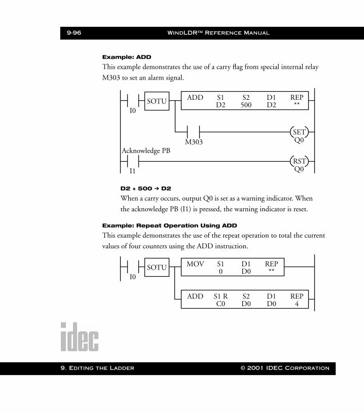
9-96 WindLDR™ Reference Manual
9. Editing t
WLDR ReferenceBook Page 96 Thursday, April 5, 2001 3:36 PM
Example: ADD
This example demonstrates the use of a carry flag from special internal relay
M303 to set an alarm signal.
D2 + 500 ➔ D2
When a carry occurs, output Q0 is set as a warning indicator. When
the acknowledge PB (I1) is pressed, the warning indicator is reset.
Example: Repeat Operation Using ADD
This example demonstrates the use of the repeat operation to total the current
values of four counters using the ADD instruction.
ADD S1 D1 REPD2 D2 **
S2500
Q0M303
I0SOTU
SET
Q0RST
Acknowledge PB
I1
I0
MOV S1 REP0 **
D1D0
ADD S1 R D1 REPC0 D0 4
S2D0
SOTU
he Ladder © 2001 IDEC Corporation
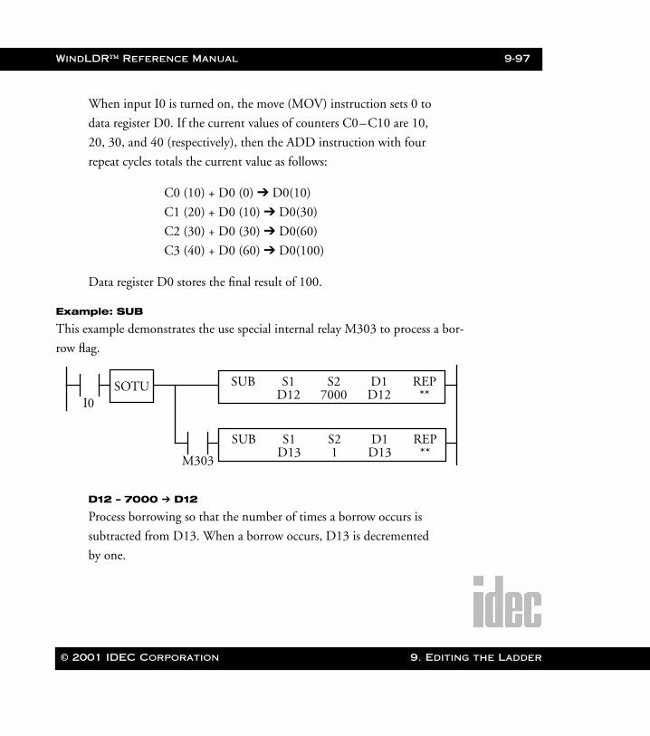
WindLDR™ Reference Manual 9-97
WLDR ReferenceBook Page 97 Thursday, April 5, 2001 3:36 PM
When input I0 is turned on, the move (MOV) instruction sets 0 to
data register D0. If the current values of counters C0–C10 are 10,
20, 30, and 40 (respectively), then the ADD instruction with four
repeat cycles totals the current value as follows:
C0 (10) + D0 (0) ➔ D0(10)
C1 (20) + D0 (10) ➔ D0(30)
C2 (30) + D0 (30) ➔ D0(60)
C3 (40) + D0 (60) ➔ D0(100)
Data register D0 stores the final result of 100.
Example: SUB
This example demonstrates the use special internal relay M303 to process a bor-
row flag.
D12 – 7000 ➔ D12
Process borrowing so that the number of times a borrow occurs is
subtracted from D13. When a borrow occurs, D13 is decremented
by one.
I0SOTU
M303
SUB S1 D1 REPD13 D13 **
S21
SUB S1 D1 REPD12 D12 **
S27000
© 2001 IDEC Corporation 9. Editing the Ladder
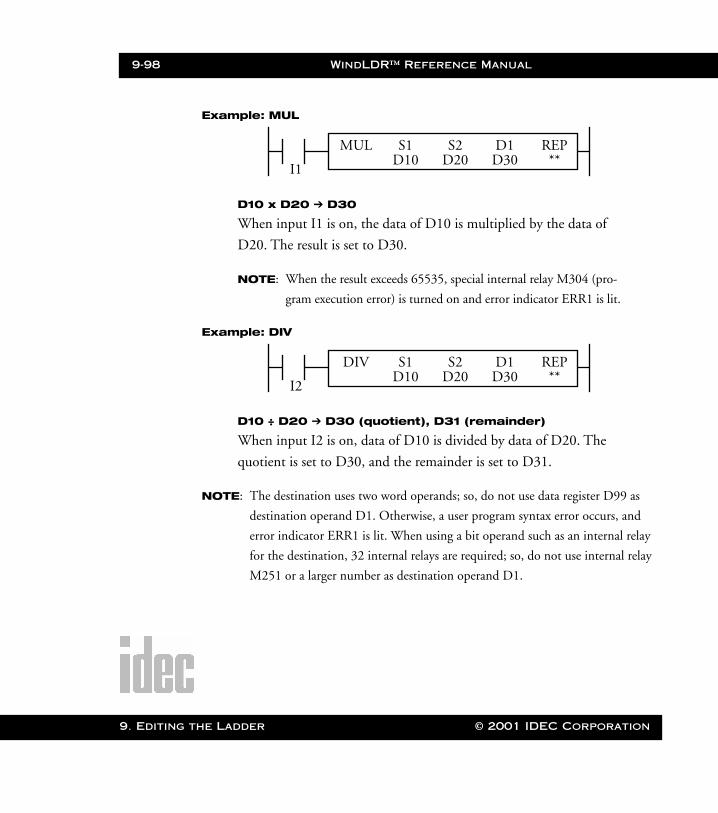
9-98 WindLDR™ Reference Manual
9. Editing t
WLDR ReferenceBook Page 98 Thursday, April 5, 2001 3:36 PM
Example: MUL
D10 x D20 ➔ D30
When input I1 is on, the data of D10 is multiplied by the data of
D20. The result is set to D30.
NOTE: When the result exceeds 65535, special internal relay M304 (pro-
gram execution error) is turned on and error indicator ERR1 is lit.
Example: DIV
D10 ÷ D20 ➔ D30 (quotient), D31 (remainder)
When input I2 is on, data of D10 is divided by data of D20. The
quotient is set to D30, and the remainder is set to D31.
NOTE: The destination uses two word operands; so, do not use data register D99 as
destination operand D1. Otherwise, a user program syntax error occurs, and
error indicator ERR1 is lit. When using a bit operand such as an internal relay
for the destination, 32 internal relays are required; so, do not use internal relay
M251 or a larger number as destination operand D1.
I1
MUL S1 D1 REPD10 D30 **
S2D20
I2
DIV S1 D1 REPD10 D30 **
S2D20
he Ladder © 2001 IDEC Corporation
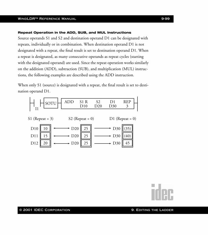
WindLDR™ Reference Manual 9-99
WLDR ReferenceBook Page 99 Thursday, April 5, 2001 3:36 PM
Repeat Operation in the ADD, SUB, and MUL Instructions
Source operands S1 and S2 and destination operand D1 can be designated with
repeats, individually or in combination. When destination operand D1 is not
designated with a repeat, the final result is set to destination operand D1. When
a repeat is designated, as many consecutive operands as repeat cycles (starting
with the designated operand) are used. Since the repeat operation works similarly
on the addition (ADD), subtraction (SUB), and multiplication (MUL) instruc-
tions, the following examples are described using the ADD instruction.
When only S1 (source) is designated with a repeat, the final result is set to desti-
nation operand D1.
I1SOTU ADD S1 R D1 REP
D10 D30 3S2
D20
D10 10
D11
D12
15
20
S1 (Repeat = 3)
D20 25
D20
D20
25
25
S2 (Repeat = 0)
D30 (35)
D30
D30
(40)
45
D1 (Repeat = 0)
© 2001 IDEC Corporation 9. Editing the Ladder
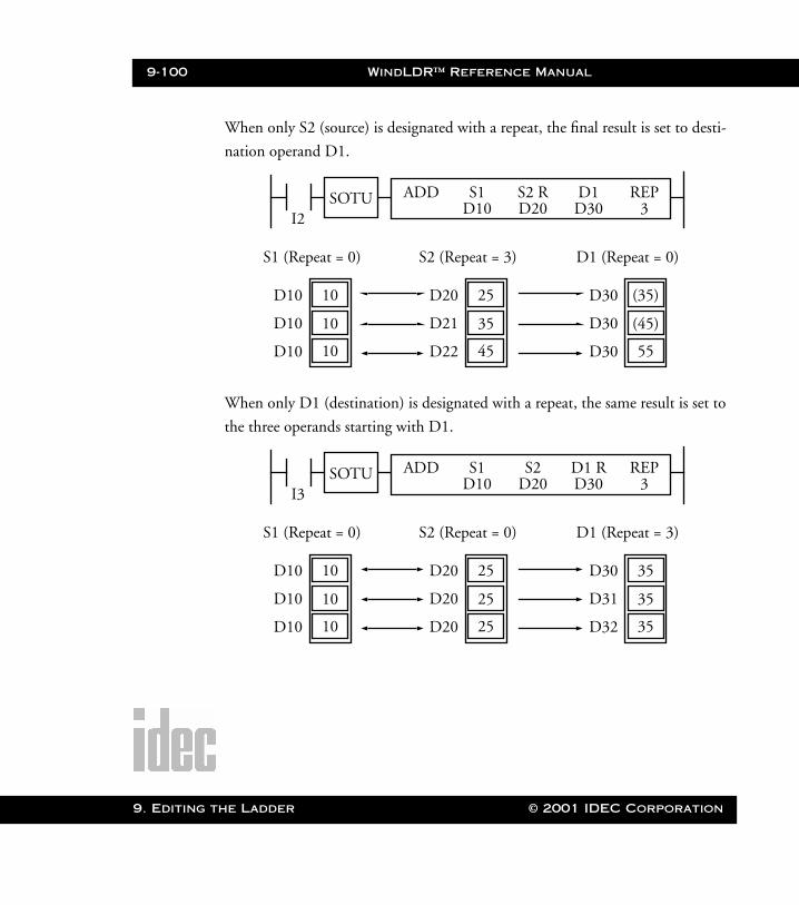
9-100 WindLDR™ Reference Manual
9. Editing t
WLDR ReferenceBook Page 100 Thursday, April 5, 2001 3:36 PM
When only S2 (source) is designated with a repeat, the final result is set to desti-
nation operand D1.
When only D1 (destination) is designated with a repeat, the same result is set to
the three operands starting with D1.
I2SOTU ADD S1 D1 REP
D10 D30 3S2 RD20
D10 10
D10
D10
10
10
S1 (Repeat = 0)
D20 25
D21
D22
35
45
S2 (Repeat = 3)
D30 (35)
D30
D30
(45)
55
D1 (Repeat = 0)
I3SOTU ADD S1 D1 R REP
D10 D30 3S2
D20
D10 10
D10
D10
10
10
S1 (Repeat = 0)
D20 25
D20
D20
25
25
S2 (Repeat = 0)
D30 35
D31
D32
35
35
D1 (Repeat = 3)
he Ladder © 2001 IDEC Corporation
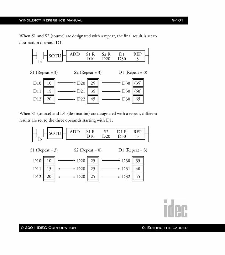
WindLDR™ Reference Manual 9-101
WLDR ReferenceBook Page 101 Thursday, April 5, 2001 3:36 PM
When S1 and S2 (source) are designated with a repeat, the final result is set to
destination operand D1.
When S1 (source) and D1 (destination) are designated with a repeat, different
results are set to the three operands starting with D1.
I4SOTU ADD S1 R D1 REP
D10 D30 3S2 RD20
D10 10
D11
D12
15
20
S1 (Repeat = 3)
D20 25
D21
D22
35
45
S2 (Repeat = 3)
D30 (35)
D30
D30
(50)
65
D1 (Repeat = 0)
I5SOTU ADD S1 R D1 R REP
D10 D30 3S2
D20
D10 10
D11
D12
15
20
S1 (Repeat = 3)
D20 25
D20
D20
25
25
S2 (Repeat = 0)
D30 35
D31
D32
40
45
D1 (Repeat = 3)
© 2001 IDEC Corporation 9. Editing the Ladder

9-102 WindLDR™ Reference Manual
9. Editing t
WLDR ReferenceBook Page 102 Thursday, April 5, 2001 3:36 PM
When S2 (source) and D1 (destination) are designated with a repeat, different
results are set to the three operands starting with D1.
I6SOTU ADD S1 D1 R REP
D10 D30 3S2 RD20
D10 10
D10
D10
10
10
S1 (Repeat = 0)
D20 25
D21
D22
35
45
S2 (Repeat = 3)
D30 35
D31
D32
45
55
D1 (Repeat = 3)
he Ladder © 2001 IDEC Corporation
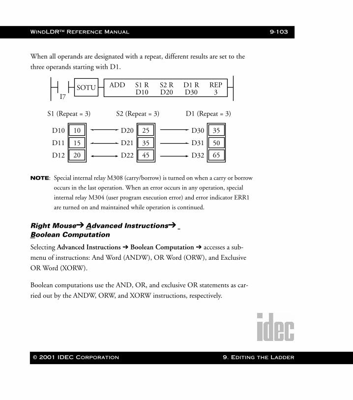
WindLDR™ Reference Manual 9-103
WLDR ReferenceBook Page 103 Thursday, April 5, 2001 3:36 PM
When all operands are designated with a repeat, different results are set to the
three operands starting with D1.
NOTE: Special internal relay M308 (carry/borrow) is turned on when a carry or borrow
occurs in the last operation. When an error occurs in any operation, special
internal relay M304 (user program execution error) and error indicator ERR1
are turned on and maintained while operation is continued.
Right Mouse➔ Advanced Instructions➔ Boolean Computation
Selecting Advanced Instructions ➔ Boolean Computation ➔ accesses a sub-
menu of instructions: And Word (ANDW), OR Word (ORW), and Exclusive
OR Word (XORW).
Boolean computations use the AND, OR, and exclusive OR statements as car-
ried out by the ANDW, ORW, and XORW instructions, respectively.
I7SOTU ADD S1 R D1 R REP
D10 D30 3S2 RD20
D10 10
D11
D12
15
20
S1 (Repeat = 3)
D20 25
D21
D22
35
45
S2 (Repeat = 3)
D30 35
D31
D32
50
65
D1 (Repeat = 3)
© 2001 IDEC Corporation 9. Editing the Ladder
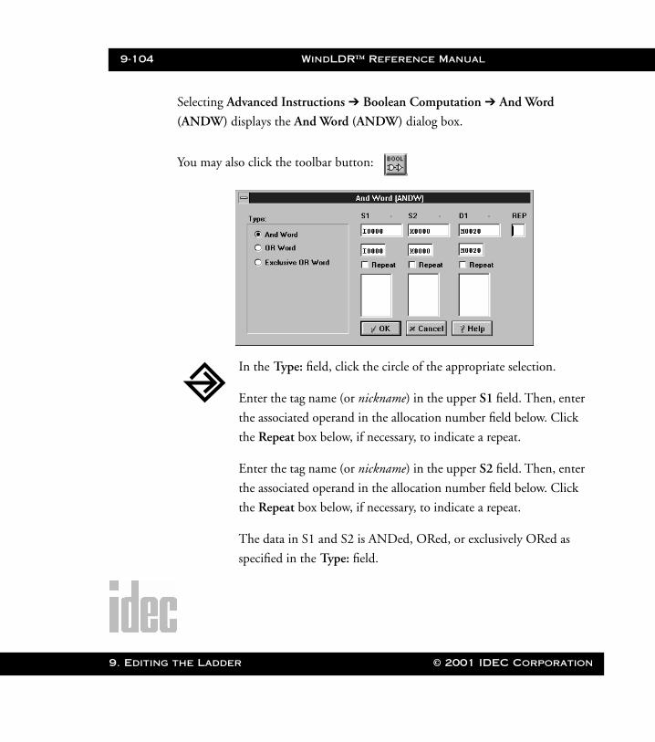
9-104 WindLDR™ Reference Manual
9. Editing
WLDR ReferenceBook Page 104 Thursday, April 5, 2001 3:36 PM
Selecting Advanced Instructions ➔ Boolean Computation ➔ And Word
(ANDW) displays the And Word (ANDW) dialog box.
You may also click the toolbar button:
In the Type: field, click the circle of the appropriate selection.
Enter the tag name (or nickname) in the upper S1 field. Then, enter
the associated operand in the allocation number field below. Click
the Repeat box below, if necessary, to indicate a repeat.
Enter the tag name (or nickname) in the upper S2 field. Then, enter
the associated operand in the allocation number field below. Click
the Repeat box below, if necessary, to indicate a repeat.
The data in S1 and S2 is ANDed, ORed, or exclusively ORed as
specified in the Type: field.
the Ladder © 2001 IDEC Corporation
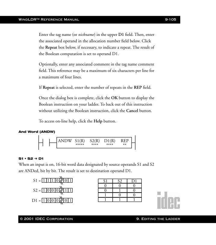
WindLDR™ Reference Manual 9-105
WLDR ReferenceBook Page 105 Thursday, April 5, 2001 3:36 PM
Enter the tag name (or nickname) in the upper D1 field. Then, enter
the associated operand in the allocation number field below. Click
the Repeat box below, if necessary, to indicate a repeat. The result of
the Boolean computation is set to operand D1.
Optionally, enter any associated comment in the tag name comment
field. This reference may be a maximum of six characters per line for
a maximum of four lines.
If Repeat is selected, enter the number of repeats in the REP field.
Once the dialog box is complete, click the OK button to display the
Boolean instruction on your ladder. To back out of this instruction
without utilizing the Boolean instruction, click the Cancel button.
To access on-line help, click the Help button.
And Word (ANDW)
S1 • S2 ➔ D1
When an input is on, 16-bit word data designated by source operands S1 and S2
are ANDed, bit by bit. The result is set to destination operand D1.
ANDW S1(R) D1(R) REP***** **** **
S2(R)****
S1 =
S2 =
D1 =
S1
1 0 0 0 11
1 1 1 0 10
1 0 0 0 10
S2 D10 0 00 1 01 0 01 1 1
© 2001 IDEC Corporation 9. Editing the Ladder
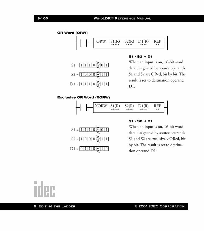
9-106 WindLDR™ Reference Manual
9. Editing t
WLDR ReferenceBook Page 106 Thursday, April 5, 2001 3:36 PM
OR Word (ORW)
Exclusive OR Word (XORW)
ORW S1(R) D1(R) REP***** **** **
S2(R)****
S1 =
S2 =
D1 =
1 0 0 0 11
1 1 1 0 10
1 1 1 0 11
S1 • S2 ➔ D1
When an input is on, 16-bit word
data designated by source operands
S1 and S2 are ORed, bit by bit. The
result is set to destination operand
D1.
XORW S1(R) D1(R) REP***** **** **
S2(R)****
S1 =
S2 =
D1 =
1 0 0 0 11
1 1 1 0 10
0 1 1 0 01
S1 • S2 ➔ D1
When an input is on, 16-bit word
data designated by source operands
S1 and S2 are exclusively ORed, bit
by bit. The result is set to destina-
tion operand D1.
he Ladder © 2001 IDEC Corporation
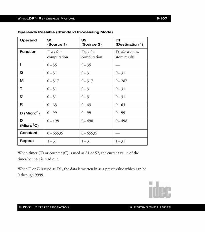
WindLDR™ Reference Manual 9-107
WLDR ReferenceBook Page 107 Thursday, April 5, 2001 3:36 PM
Operands Possible (Standard Processing Mode)
When timer (T) or counter (C) is used as S1 or S2, the current value of the
timer/counter is read out.
When T or C is used as D1, the data is written in as a preset value which can be
0 through 9999.
Operand S1 (Source 1)
S2 (Source 2)
D1 (Destination 1)
Function Data for computation
Data for computation
Destination to store results
I 0 – 35 0 – 35 —
Q 0 – 31 0 – 31 0 – 31
M 0 – 317 0 – 317 0 – 287
T 0 – 31 0 – 31 0 – 31
C 0 – 31 0 – 31 0 – 31
R 0 – 63 0 – 63 0 – 63
D (Micro3) 0 – 99 0 – 99 0 – 99
D (Micro3C)
0 – 498 0 – 498 0 – 498
Constant 0 – 65535 0 – 65535 —
Repeat 1 – 31 1 – 31 1 – 31
© 2001 IDEC Corporation 9. Editing the Ladder
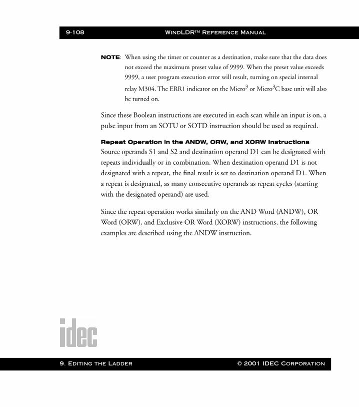
9-108 WindLDR™ Reference Manual
9. Editing t
WLDR ReferenceBook Page 108 Thursday, April 5, 2001 3:36 PM
NOTE: When using the timer or counter as a destination, make sure that the data does
not exceed the maximum preset value of 9999. When the preset value exceeds
9999, a user program execution error will result, turning on special internal
relay M304. The ERR1 indicator on the Micro3 or Micro3C base unit will also
be turned on.
Since these Boolean instructions are executed in each scan while an input is on, a
pulse input from an SOTU or SOTD instruction should be used as required.
Repeat Operation in the ANDW, ORW, and XORW Instructions
Source operands S1 and S2 and destination operand D1 can be designated with
repeats individually or in combination. When destination operand D1 is not
designated with a repeat, the final result is set to destination operand D1. When
a repeat is designated, as many consecutive operands as repeat cycles (starting
with the designated operand) are used.
Since the repeat operation works similarly on the AND Word (ANDW), OR
Word (ORW), and Exclusive OR Word (XORW) instructions, the following
examples are described using the ANDW instruction.
he Ladder © 2001 IDEC Corporation
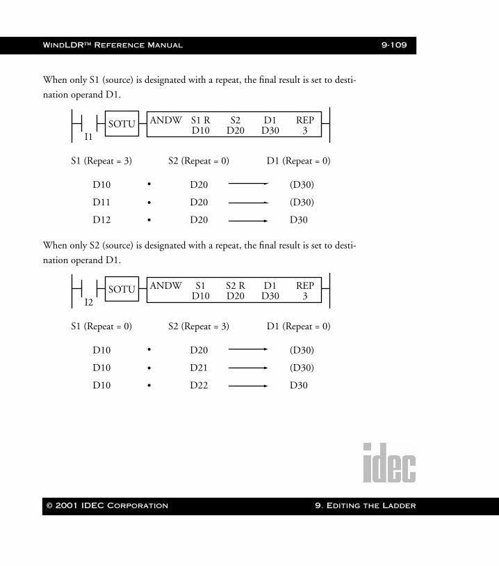
WindLDR™ Reference Manual 9-109
WLDR ReferenceBook Page 109 Thursday, April 5, 2001 3:36 PM
When only S1 (source) is designated with a repeat, the final result is set to desti-
nation operand D1.
When only S2 (source) is designated with a repeat, the final result is set to desti-
nation operand D1.
I1SOTU ANDW S1 R D1 REP
D10 D30 3S2
D20
D10
D11
D12
S1 (Repeat = 3)
D20
D20
D20
S2 (Repeat = 0)
(D30)
(D30)
D30
D1 (Repeat = 0)
•
•
•
I2SOTU ANDW S1 D1 REP
D10 D30 3S2 RD20
D10
D10
D10
S1 (Repeat = 0)
D20
D21
D22
S2 (Repeat = 3)
(D30)
(D30)
D30
D1 (Repeat = 0)
•
•
•
© 2001 IDEC Corporation 9. Editing the Ladder
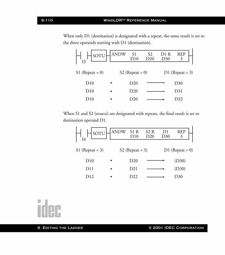
9-110 WindLDR™ Reference Manual
9. Editing t
WLDR ReferenceBook Page 110 Thursday, April 5, 2001 3:36 PM
When only D1 (destination) is designated with a repeat, the same result is set to
the three operands starting with D1 (destination).
When S1 and S2 (source) are designated with repeats, the final result is set to
destination operand D1.
I3SOTU ANDW S1 D1 R REP
D10 D30 3S2
D20
D10
D10
D10
S1 (Repeat = 0)
D20
D20
D20
S2 (Repeat = 0)
D30
D31
D32
D1 (Repeat = 3)
•
•
•
I4SOTU ANDW S1 R D1 REP
D10 D30 3S2 RD20
D10
D11
D12
S1 (Repeat = 3)
D20
D21
D22
S2 (Repeat = 3)
(D30)
(D30)
D30
D1 (Repeat = 0)
•
•
•
he Ladder © 2001 IDEC Corporation

WindLDR™ Reference Manual 9-111
WLDR ReferenceBook Page 111 Thursday, April 5, 2001 3:36 PM
When S1 (source) and D1 (destination) are designated with repeats, different
results are set to the three operands starting with D1.
When S2 (source) and D1 (destination) are designated with repeats, different
results are set to the three operands starting with D1.
I5SOTU ANDW S1 R D1 R REP
D10 D30 3S2
D20
D10
D11
D12
S1 (Repeat = 3)
D20
D20
D20
S2 (Repeat = 0)
D30
D31
D32
D1 (Repeat = 3)
•
•
•
I6SOTU ANDW S1 D1 R REP
D10 D30 3S2 RD20
D10
D10
D10
S1 (Repeat = 0)
D20
D21
D22
S2 (Repeat = 3)
D30
D31
D32
D1 (Repeat = 3)
•
•
•
© 2001 IDEC Corporation 9. Editing the Ladder
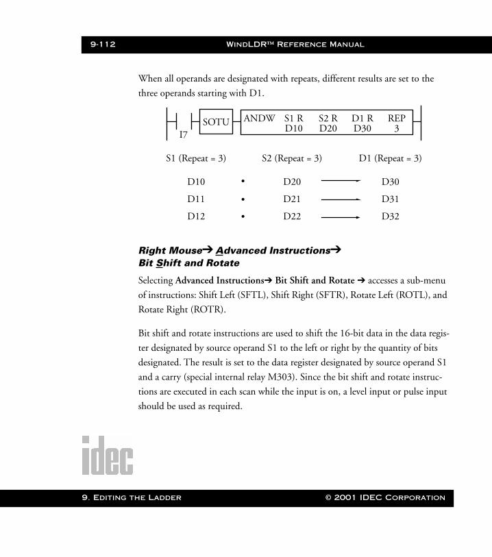
9-112 WindLDR™ Reference Manual
9. Editing t
WLDR ReferenceBook Page 112 Thursday, April 5, 2001 3:36 PM
When all operands are designated with repeats, different results are set to the
three operands starting with D1.
Right Mouse➔ Advanced Instructions➔ Bit Shift and Rotate
Selecting Advanced Instructions➔ Bit Shift and Rotate ➔ accesses a sub-menu
of instructions: Shift Left (SFTL), Shift Right (SFTR), Rotate Left (ROTL), and
Rotate Right (ROTR).
Bit shift and rotate instructions are used to shift the 16-bit data in the data regis-
ter designated by source operand S1 to the left or right by the quantity of bits
designated. The result is set to the data register designated by source operand S1
and a carry (special internal relay M303). Since the bit shift and rotate instruc-
tions are executed in each scan while the input is on, a level input or pulse input
should be used as required.
I7SOTU ANDW S1 R D1 R REP
D10 D30 3S2 RD20
D10
D11
D12
S1 (Repeat = 3)
D20
D21
D22
S2 (Repeat = 3)
D30
D31
D32
D1 (Repeat = 3)
•
•
•
he Ladder © 2001 IDEC Corporation
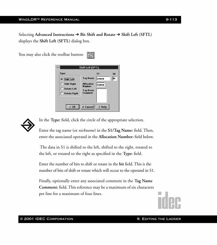
WindLDR™ Reference Manual 9-113
WLDR ReferenceBook Page 113 Thursday, April 5, 2001 3:36 PM
Selecting Advanced Instructions ➔ Bit Shift and Rotate ➔ Shift Left (SFTL)
displays the Shift Left (SFTL) dialog box.
You may also click the toolbar button:
In the Type: field, click the circle of the appropriate selection.
Enter the tag name (or nickname) in the S1/Tag Name: field. Then,
enter the associated operand in the Allocation Number: field below.
The data in S1 is shifted to the left, shifted to the right, rotated to
the left, or rotated to the right as specified in the Type: field.
Enter the number of bits to shift or rotate in the bit field. This is the
number of bits of shift or rotate which will occur to the operand in S1.
Finally, optionally enter any associated comment in the Tag Name
Comment: field. This reference may be a maximum of six characters
per line for a maximum of four lines.
© 2001 IDEC Corporation 9. Editing the Ladder
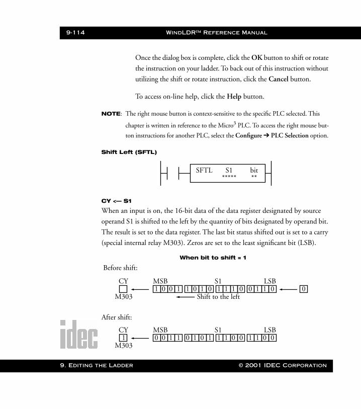
9-114 WindLDR™ Reference Manual
9. Editing t
WLDR ReferenceBook Page 114 Thursday, April 5, 2001 3:36 PM
Once the dialog box is complete, click the OK button to shift or rotate
the instruction on your ladder. To back out of this instruction without
utilizing the shift or rotate instruction, click the Cancel button.
To access on-line help, click the Help button.
NOTE: The right mouse button is context-sensitive to the specific PLC selected. This
chapter is written in reference to the Micro3 PLC. To access the right mouse but-
ton instructions for another PLC, select the Configure ➔ PLC Selection option.
Shift Left (SFTL)
CY <— S1
When an input is on, the 16-bit data of the data register designated by source
operand S1 is shifted to the left by the quantity of bits designated by operand bit.
The result is set to the data register. The last bit status shifted out is set to a carry
(special internal relay M303). Zeros are set to the least significant bit (LSB).
SFTL S1*****
bit**
1 0 0 1 0
When bit to shift = 1
Before shift:
After shift:
CY
M303
MSB S1 LSB
Shift to the left1 0 1 0 1 1 1 0 0 1 1 0
0 0 1 11CY
M303
MSB S1 LSB0 1 0 1 1 1 0 0 1 1 0 0
he Ladder © 2001 IDEC Corporation
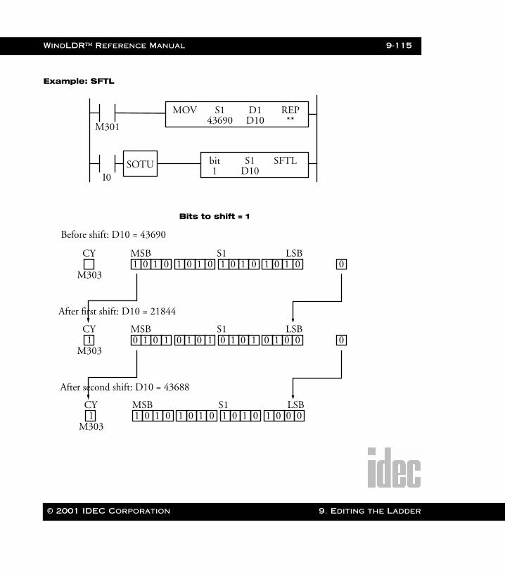
WindLDR™ Reference Manual 9-115
WLDR ReferenceBook Page 115 Thursday, April 5, 2001 3:36 PM
Example: SFTL
M301
MOV S1 REP43690 **
D1D10
I0SOTU SFTLS1
D10bit1
1 0 1 0 0
Bits to shift = 1
Before shift: D10 = 43690
After first shift: D10 = 21844
CY
M303
MSB S1 LSB1 0 1 0 1 0 1 0 1 0 1 0
0 1 0 11CY
M303
MSB S1 LSB0 1 0 1 0 1 0 1 0 1 0 0
After second shift: D10 = 43688
1 0 1 01CY
M303
MSB S1 LSB1 0 1 0 1 0 1 0 1 0 0 0
0
© 2001 IDEC Corporation 9. Editing the Ladder
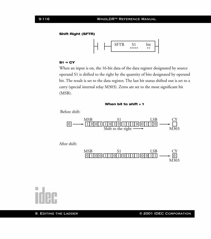
9-116 WindLDR™ Reference Manual
9. Editing t
WLDR ReferenceBook Page 116 Thursday, April 5, 2001 3:36 PM
Shift Right (SFTR)
S1 ➔ CY
When an input is on, the 16-bit data of the data register designated by source
operand S1 is shifted to the right by the quantity of bits designated by operand
bit. The result is set to the data register. The last bit status shifted out is set to a
carry (special internal relay M303). Zeros are set to the most significant bit
(MSB).
SFTR S1*****
bit**
01100
When bit to shift = 1
Before shift:
After shift:
CY
M303
LSBS1MSB
Shift to the right011101011001
1100 0CY
M303
LSBS1MSB111010110010
he Ladder © 2001 IDEC Corporation
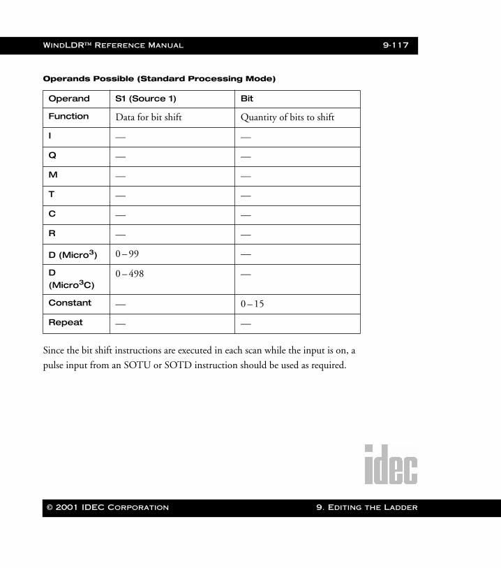
WindLDR™ Reference Manual 9-117
WLDR ReferenceBook Page 117 Thursday, April 5, 2001 3:36 PM
Operands Possible (Standard Processing Mode)
Since the bit shift instructions are executed in each scan while the input is on, a
pulse input from an SOTU or SOTD instruction should be used as required.
Operand S1 (Source 1) Bit
Function Data for bit shift Quantity of bits to shift
I — —
Q — —
M — —
T — —
C — —
R — —
D (Micro3) 0 – 99 —
D (Micro3C)
0 – 498 —
Constant — 0 – 15
Repeat — —
© 2001 IDEC Corporation 9. Editing the Ladder
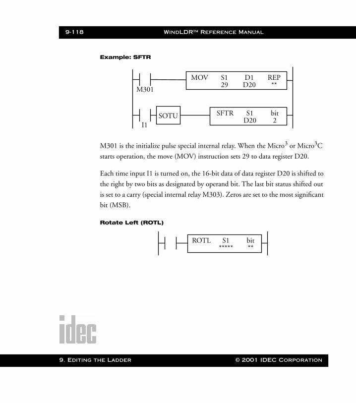
9-118 WindLDR™ Reference Manual
9. Editing t
WLDR ReferenceBook Page 118 Thursday, April 5, 2001 3:36 PM
Example: SFTR
M301 is the initialize pulse special internal relay. When the Micro3 or Micro3C
starts operation, the move (MOV) instruction sets 29 to data register D20.
Each time input I1 is turned on, the 16-bit data of data register D20 is shifted to
the right by two bits as designated by operand bit. The last bit status shifted out
is set to a carry (special internal relay M303). Zeros are set to the most significant
bit (MSB).
Rotate Left (ROTL)
M301
MOV S1 REP29 **
D1D20
I1SOTU SFTR S1
D20bit2
ROTL S1*****
bit**
he Ladder © 2001 IDEC Corporation
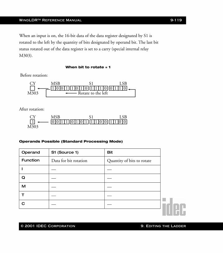
WindLDR™ Reference Manual 9-119
WLDR ReferenceBook Page 119 Thursday, April 5, 2001 3:36 PM
When an input is on, the 16-bit data of the data register designated by S1 is
rotated to the left by the quantity of bits designated by operand bit. The last bit
status rotated out of the data register is set to a carry (special internal relay
M303).
Operands Possible (Standard Processing Mode)
Operand S1 (Source 1) Bit
Function Data for bit rotation Quantity of bits to rotate
I — —
Q — —
M — —
T — —
C — —
1 0 0 1
When bit to rotate = 1
Before rotation:
After rotation:
CY
M303
MSB S1 LSB
Rotate to the left1 0 1 0 1 1 1 0 0 1 1 0
0 0 1 11CY
M303
MSB S1 LSB0 1 0 1 1 1 0 0 1 1 0 0
© 2001 IDEC Corporation 9. Editing the Ladder
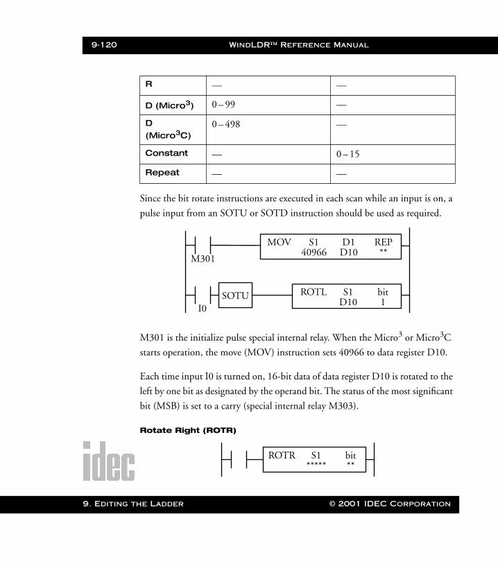
9-120 WindLDR™ Reference Manual
9. Editing t
WLDR ReferenceBook Page 120 Thursday, April 5, 2001 3:36 PM
Since the bit rotate instructions are executed in each scan while an input is on, a
pulse input from an SOTU or SOTD instruction should be used as required.
M301 is the initialize pulse special internal relay. When the Micro3 or Micro3C
starts operation, the move (MOV) instruction sets 40966 to data register D10.
Each time input I0 is turned on, 16-bit data of data register D10 is rotated to the
left by one bit as designated by the operand bit. The status of the most significant
bit (MSB) is set to a carry (special internal relay M303).
Rotate Right (ROTR)
R — —
D (Micro3) 0 – 99 —
D (Micro3C)
0 – 498 —
Constant — 0 – 15
Repeat — —
M301
MOV S1 REP40966 **
D1D10
I0SOTU ROTL S1
D10bit1
ROTR S1*****
bit**
he Ladder © 2001 IDEC Corporation
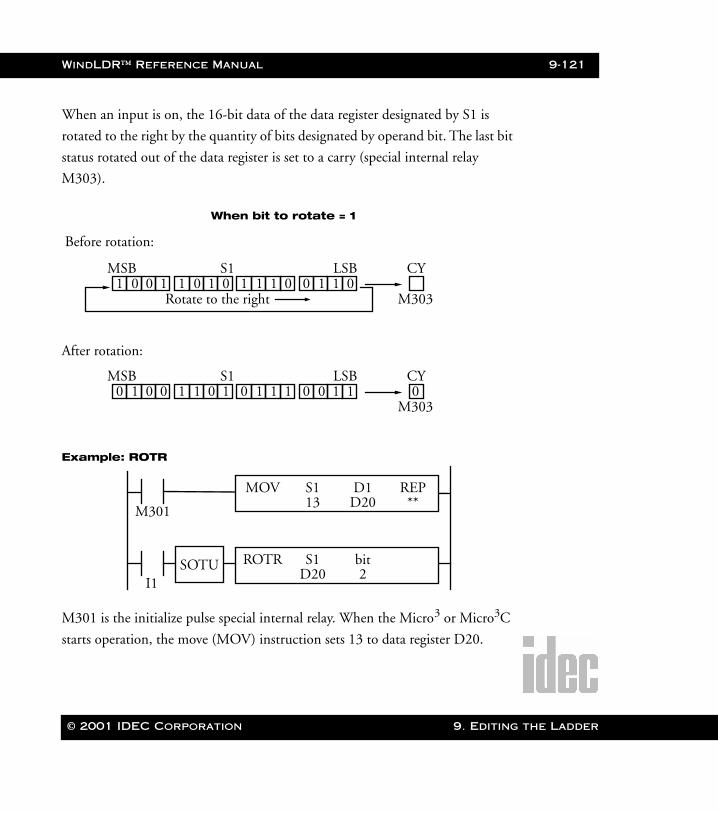
WindLDR™ Reference Manual 9-121
WLDR ReferenceBook Page 121 Thursday, April 5, 2001 3:36 PM
When an input is on, the 16-bit data of the data register designated by S1 is
rotated to the right by the quantity of bits designated by operand bit. The last bit
status rotated out of the data register is set to a carry (special internal relay
M303).
Example: ROTR
M301 is the initialize pulse special internal relay. When the Micro3 or Micro3C
starts operation, the move (MOV) instruction sets 13 to data register D20.
0110
When bit to rotate = 1
Before rotation:
After rotation:
CY
M303
LSBS1MSB
Rotate to the right011101011001
1100 0CY
M303
LSBS1MSB111010110010
M301
MOV S1 REP13 **
D1D20
I1SOTU ROTR S1
D20bit2
© 2001 IDEC Corporation 9. Editing the Ladder
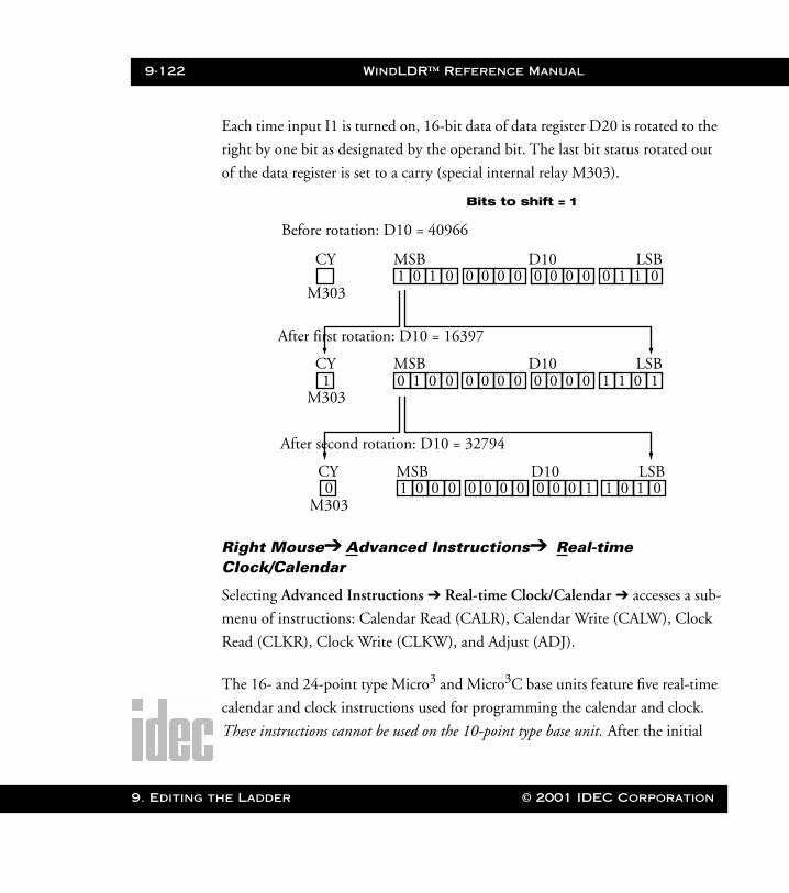
9-122 WindLDR™ Reference Manual
9. Editing t
WLDR ReferenceBook Page 122 Thursday, April 5, 2001 3:36 PM
Each time input I1 is turned on, 16-bit data of data register D20 is rotated to the
right by one bit as designated by the operand bit. The last bit status rotated out
of the data register is set to a carry (special internal relay M303).
Right Mouse➔ Advanced Instructions➔ Real-timeClock/Calendar
Selecting Advanced Instructions ➔ Real-time Clock/Calendar ➔ accesses a sub-
menu of instructions: Calendar Read (CALR), Calendar Write (CALW), Clock
Read (CLKR), Clock Write (CLKW), and Adjust (ADJ).
The 16- and 24-point type Micro3 and Micro3C base units feature five real-time
calendar and clock instructions used for programming the calendar and clock.
These instructions cannot be used on the 10-point type base unit. After the initial
1 0 1 0
Bits to shift = 1
Before rotation: D10 = 40966
After first rotation: D10 = 16397
CY
M303
MSB D10 LSB0 0 0 0 0 0 0 0 0 1 1 0
0 1 0 01CY
M303
MSB D10 LSB0 0 0 0 0 0 0 0 1 1 0 1
After second rotation: D10 = 32794
1 0 0 00CY
M303
MSB D10 LSB0 0 0 0 0 0 0 1 1 0 1 0
he Ladder © 2001 IDEC Corporation
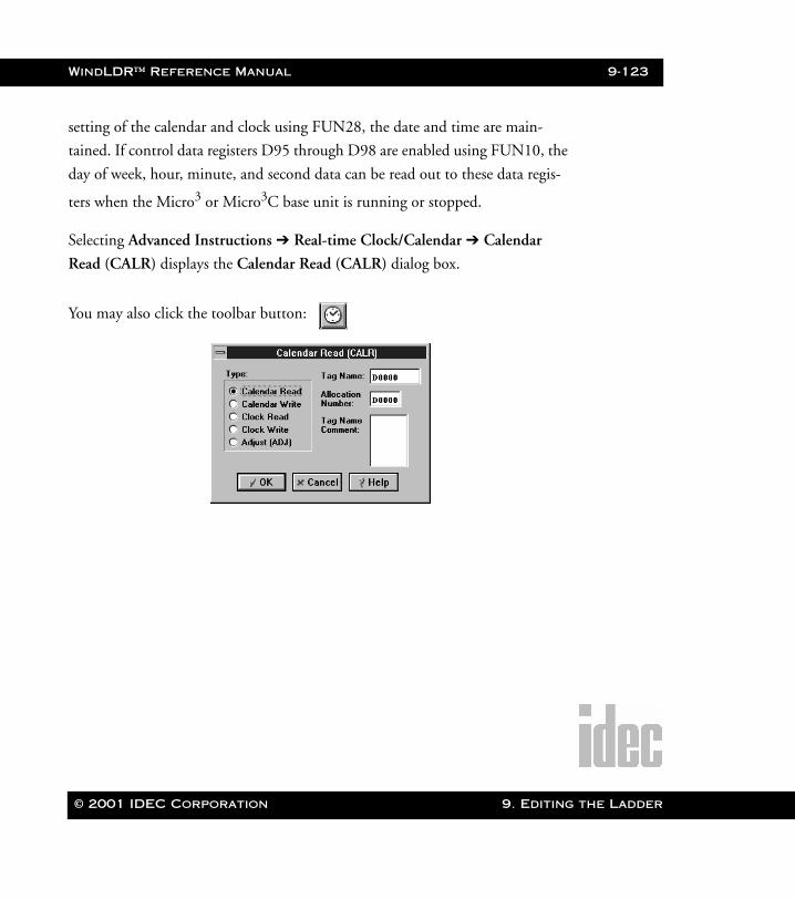
WindLDR™ Reference Manual 9-123
WLDR ReferenceBook Page 123 Thursday, April 5, 2001 3:36 PM
setting of the calendar and clock using FUN28, the date and time are main-
tained. If control data registers D95 through D98 are enabled using FUN10, the
day of week, hour, minute, and second data can be read out to these data regis-
ters when the Micro3 or Micro3C base unit is running or stopped.
Selecting Advanced Instructions ➔ Real-time Clock/Calendar ➔ Calendar
Read (CALR) displays the Calendar Read (CALR) dialog box.
You may also click the toolbar button:
© 2001 IDEC Corporation 9. Editing the Ladder
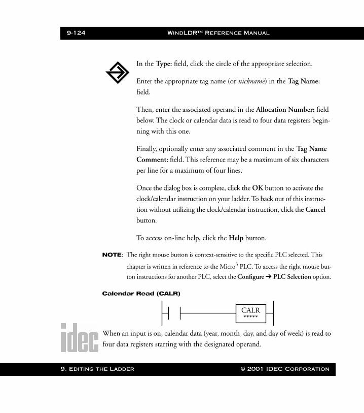
9-124 WindLDR™ Reference Manual
9. Editing t
WLDR ReferenceBook Page 124 Thursday, April 5, 2001 3:36 PM
NOTE: The right mouse button is context-sensitive to the specific PLC selected. This
chapter is written in reference to the Micro3 PLC. To access the right mouse but-
ton instructions for another PLC, select the Configure ➔ PLC Selection option.
Calendar Read (CALR)
When an input is on, calendar data (year, month, day, and day of week) is read to
four data registers starting with the designated operand.
In the Type: field, click the circle of the appropriate selection.
Enter the appropriate tag name (or nickname) in the Tag Name:
field.
Then, enter the associated operand in the Allocation Number: field
below. The clock or calendar data is read to four data registers begin-
ning with this one.
Finally, optionally enter any associated comment in the Tag Name
Comment: field. This reference may be a maximum of six characters
per line for a maximum of four lines.
Once the dialog box is complete, click the OK button to activate the
clock/calendar instruction on your ladder. To back out of this instruc-
tion without utilizing the clock/calendar instruction, click the Cancel
button.
To access on-line help, click the Help button.
CALR*****
he Ladder © 2001 IDEC Corporation
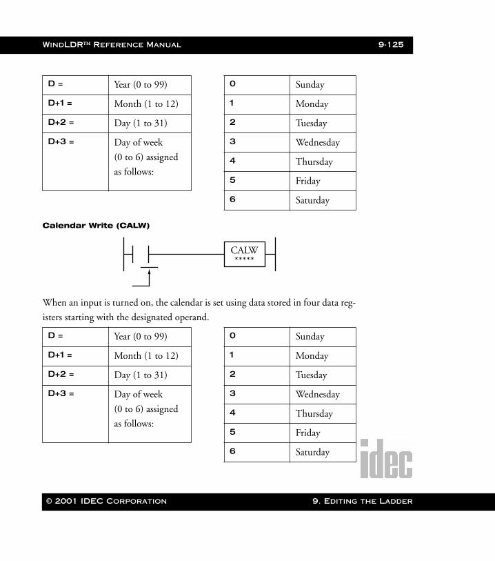
WindLDR™ Reference Manual 9-125
WLDR ReferenceBook Page 125 Thursday, April 5, 2001 3:36 PM
Calendar Write (CALW)
When an input is turned on, the calendar is set using data stored in four data reg-
isters starting with the designated operand.
D = Year (0 to 99) 0 Sunday
D+1 = Month (1 to 12) 1 Monday
D+2 = Day (1 to 31) 2 Tuesday
D+3 = Day of week
(0 to 6) assigned
as follows:
3 Wednesday
4 Thursday
5 Friday
6 Saturday
D = Year (0 to 99) 0 Sunday
D+1 = Month (1 to 12) 1 Monday
D+2 = Day (1 to 31) 2 Tuesday
D+3 = Day of week
(0 to 6) assigned
as follows:
3 Wednesday
4 Thursday
5 Friday
6 Saturday
CALW*****
© 2001 IDEC Corporation 9. Editing the Ladder
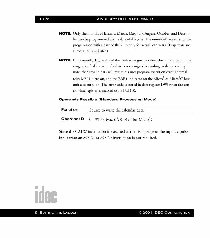
9-126 WindLDR™ Reference Manual
9. Editing t
WLDR ReferenceBook Page 126 Thursday, April 5, 2001 3:36 PM
NOTE: Only the months of January, March, May, July, August, October, and Decem-
ber can be programmed with a date of the 31st. The month of February can be
programmed with a date of the 29th only for actual leap years. (Leap years are
automatically adjusted).
NOTE: If the month, day, or day of the week is assigned a value which is not within the
range specified above or if a date is not assigned according to the preceding
note, then invalid data will result in a user program execution error. Internal
relay M304 turns on, and the ERR1 indicator on the Micro3 or Micro3C base
unit also turns on. The error code is stored in data register D93 when the con-
trol data register is enabled using FUN10.
Operands Possible (Standard Processing Mode)
Since the CALW instruction is executed at the rising edge of the input, a pulse
input from an SOTU or SOTD instruction is not required.
Function Source to write the calendar data
Operand: D 0 – 99 for Micro3; 0–498 for Micro3C
he Ladder © 2001 IDEC Corporation
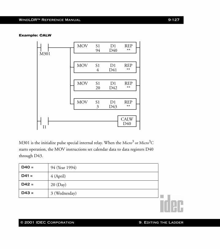
WindLDR™ Reference Manual 9-127
WLDR ReferenceBook Page 127 Thursday, April 5, 2001 3:36 PM
Example: CALW
M301 is the initialize pulse special internal relay. When the Micro3 or Micro3C
starts operation, the MOV instructions set calendar data to data registers D40
through D43.
D40 = 94 (Year 1994)
D41 = 4 (April)
D42 = 20 (Day)
D43 = 3 (Wednesday)
M301
MOV S1 REP94 **
D1D40
MOV S1 REP4 **
D1D41
MOV S1 REP20 **
D1D42
MOV S1 REP3 **
D1D43
I1
CALWD40
© 2001 IDEC Corporation 9. Editing the Ladder
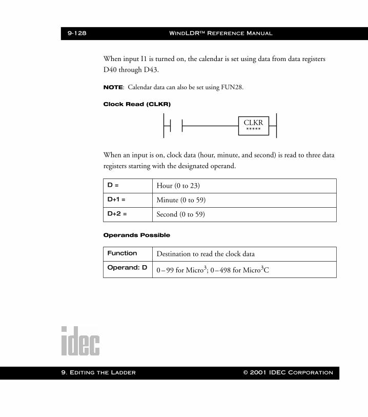
9-128 WindLDR™ Reference Manual
9. Editing t
WLDR ReferenceBook Page 128 Thursday, April 5, 2001 3:36 PM
When input I1 is turned on, the calendar is set using data from data registers
D40 through D43.
NOTE: Calendar data can also be set using FUN28.
Clock Read (CLKR)
When an input is on, clock data (hour, minute, and second) is read to three data
registers starting with the designated operand.
Operands Possible
D = Hour (0 to 23)
D+1 = Minute (0 to 59)
D+2 = Second (0 to 59)
Function Destination to read the clock data
Operand: D 0 – 99 for Micro3; 0–498 for Micro3C
CLKR*****
he Ladder © 2001 IDEC Corporation
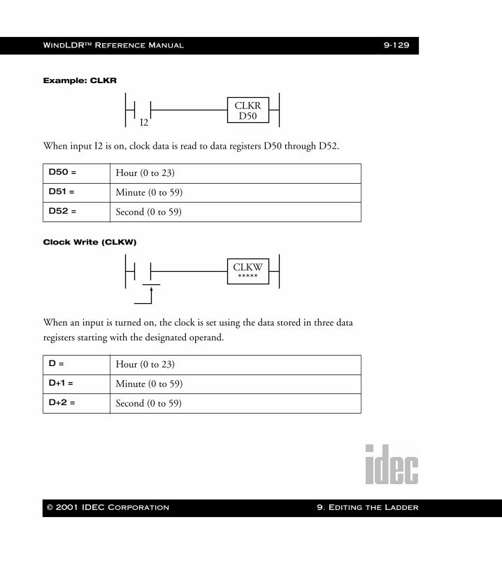
WindLDR™ Reference Manual 9-129
WLDR ReferenceBook Page 129 Thursday, April 5, 2001 3:36 PM
Example: CLKR
When input I2 is on, clock data is read to data registers D50 through D52.
Clock Write (CLKW)
When an input is turned on, the clock is set using the data stored in three data
registers starting with the designated operand.
D50 = Hour (0 to 23)
D51 = Minute (0 to 59)
D52 = Second (0 to 59)
D = Hour (0 to 23)
D+1 = Minute (0 to 59)
D+2 = Second (0 to 59)
I2
CLKRD50
CLKW*****
© 2001 IDEC Corporation 9. Editing the Ladder
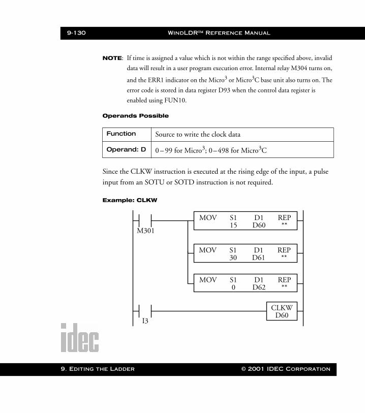
9-130 WindLDR™ Reference Manual
9. Editing t
WLDR ReferenceBook Page 130 Thursday, April 5, 2001 3:36 PM
NOTE: If time is assigned a value which is not within the range specified above, invalid
data will result in a user program execution error. Internal relay M304 turns on,
and the ERR1 indicator on the Micro3 or Micro3C base unit also turns on. The
error code is stored in data register D93 when the control data register is
enabled using FUN10.
Operands Possible
Since the CLKW instruction is executed at the rising edge of the input, a pulse
input from an SOTU or SOTD instruction is not required.
Example: CLKW
Function Source to write the clock data
Operand: D 0 – 99 for Micro3; 0–498 for Micro3C
M301
MOV S1 REP15 **
D1D60
MOV S1 REP30 **
D1D61
MOV S1 REP0 **
D1D62
I3
CLKWD60
he Ladder © 2001 IDEC Corporation
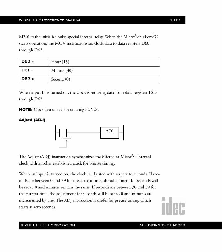
WindLDR™ Reference Manual 9-131
WLDR ReferenceBook Page 131 Thursday, April 5, 2001 3:36 PM
M301 is the initialize pulse special internal relay. When the Micro3 or Micro3C
starts operation, the MOV instructions set clock data to data registers D60
through D62.
When input I3 is turned on, the clock is set using data from data registers D60
through D62.
NOTE: Clock data can also be set using FUN28.
Adjust (ADJ)
The Adjust (ADJ) instruction synchronizes the Micro3 or Micro3C internal
clock with another established clock for precise timing.
When an input is turned on, the clock is adjusted with respect to seconds. If sec-
onds are between 0 and 29 for the current time, the adjustment for seconds will
be set to 0 and minutes remain the same. If seconds are between 30 and 59 for
the current time, the adjustment for seconds will be set to 0 and minutes are
incremented by one. The ADJ instruction is useful for precise timing which
starts at zero seconds.
D60 = Hour (15)
D61 = Minute (30)
D62 = Second (0)
ADJ
© 2001 IDEC Corporation 9. Editing the Ladder

9-132 WindLDR™ Reference Manual
9. Editing t
WLDR ReferenceBook Page 132 Thursday, April 5, 2001 3:36 PM
Since the ADJ instruction is executed at the rising edge of the input, a pulse
input from an SOTU or SOTD instruction is not required.
When input I4 is turned on, the clock is adjusted with respect to seconds.
ADJ Example: Time Scheduled Control
This example demonstrates a program to turn output Q0 on and off according
to the chart below:
I4
ADJ
Out
put Q
0
ONOFF
April 38:30
ComparisonData 1
June 116:55
ComparisonData 3
May 28:30
ComparisonData 2
July 219:50
ComparisonData 4
August 2012:05
ComparisonData 5
September 2617:20
ComparisonData 6
he Ladder © 2001 IDEC Corporation
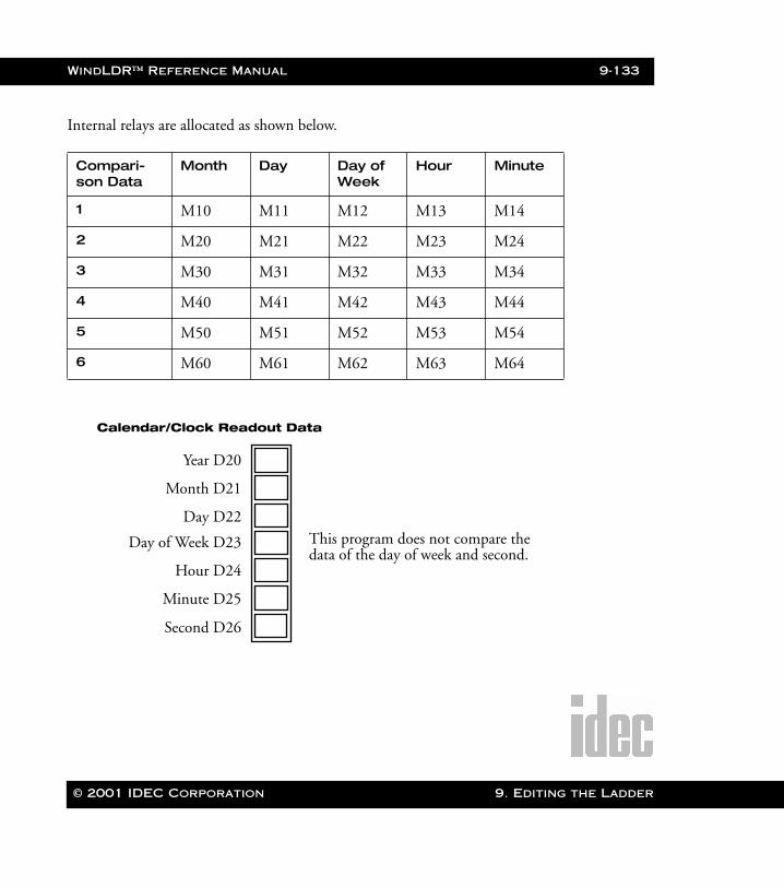
WindLDR™ Reference Manual 9-133
WLDR ReferenceBook Page 133 Thursday, April 5, 2001 3:36 PM
Internal relays are allocated as shown below.
Compari-son Data
Month Day Day of Week
Hour Minute
1 M10 M11 M12 M13 M14
2 M20 M21 M22 M23 M24
3 M30 M31 M32 M33 M34
4 M40 M41 M42 M43 M44
5 M50 M51 M52 M53 M54
6 M60 M61 M62 M63 M64
Year D20
Month D21
Day D22
Calendar/Clock Readout Data
Day of Week D23
Hour D24
Minute D25
Second D26
This program does not compare the data of the day of week and second.
© 2001 IDEC Corporation 9. Editing the Ladder

9-134 WindLDR™ Reference Manual
9. Editing t
WLDR ReferenceBook Page 134 Thursday, April 5, 2001 3:36 PM
3
Month D30
Day D31
4
Comparison Data 1
30
8
Day of Week D32
Hour D33
Minute D34
(Turn on output Q0)
M10
M11
M12
M13
M14
1
Month D40
Day D41
6
Comparison Data 3
55
16
Day of Week D42
Hour D43
Minute D44
(Turn on output Q0)
M30
M31
M32
M33
M34
2
Month D35
Day D36
5
Comparison Data 2
30
8
Day of Week D37
Hour D38
Minute D39
(Turn on output Q0)
M20
M21
M22
M23
M24
2
Month D45
Day D46
7
Comparison Data 4
50
19
Day of Week D47
Hour D48
Minute D49
(Turn on output Q0)
M40
M41
M42
M43
M44
20
Month D50
Day D51
8
Comparison Data 5
5
12
Day of Week D52
Hour D53
Minute D54
(Turn on output Q0)
M50
M51
M52
M53
M54
26
Month D55
Day D56
9
Comparison Data 6
20
17
Day of Week D57
Hour D58
Minute D59
(Turn on output Q0)
M60
M61
M62
M63
M64
he Ladder © 2001 IDEC Corporation
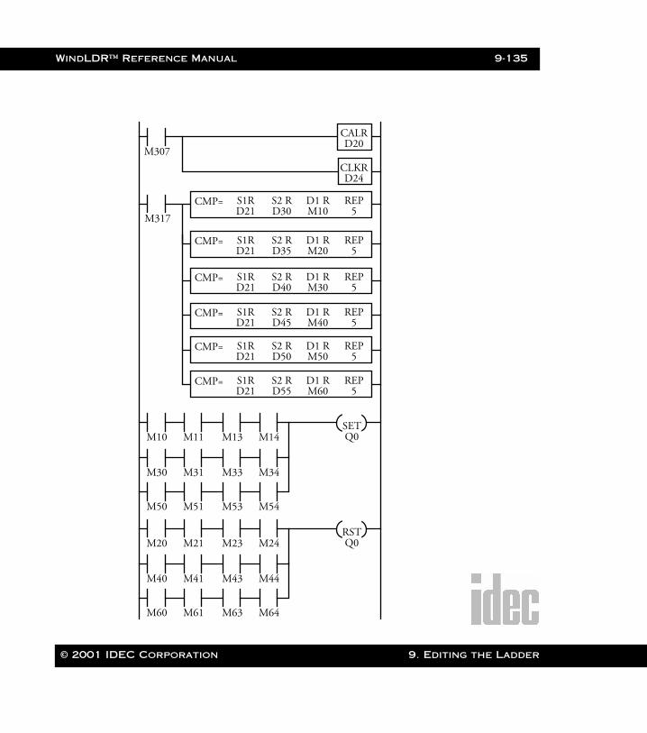
WindLDR™ Reference Manual 9-135
WLDR ReferenceBook Page 135 Thursday, April 5, 2001 3:36 PM
M307
CALRD20
CLKRD24
M317
MOV S1 REP0 **
D1D62
S10
S1R S2 R REPD30 5
D1 RM10
CMP=D21
S1R S2 R REPD35 5
D1 RM20
CMP=D21
S1R S2 R REPD40 5
D1 RM30
CMP=D21
S1R S2 R REPD45 5
D1 RM40
CMP=D21
S1R S2 R REPD50 5
D1 RM50
CMP=D21
S1R S2 R REPD55 5
D1 RM60
CMP=D21
M10 M11 M13 M14SETQ0
M30 M31 M33 M34
M50 M51 M53 M54
M20 M21 M23 M24RSTQ0
M40 M41 M43 M44
M60 M61 M63 M64
© 2001 IDEC Corporation 9. Editing the Ladder
9-136 WindLDR™ Reference Manual
9. Editing t
WLDR ReferenceBook Page 136 Thursday, April 5, 2001 3:36 PM
M317 is the in-operation special internal relay. While the program is executed,
the clock read (CLKR) instruction reads the calendar and clock data to data reg-
isters D20 (year), D21 (month), D22 (day), D23 (day of week), D24 (hour),
D25 (minute), and D26 (second).
The compare equal to (CMP=) instruction compares the current values of the
month, day, day of week, hour, and minute in data registers D21 through D25
with the comparison data in five consecutive data registers. When data matches,
a corresponding internal relay is turned on.
The first CMP= makes the following comparison and turns internal relays on:
D21 <—> D30 —> M10 (month)D22 <—> D31 —> M11 (day)D23 <—> D32 —> M12 (day of week)D24 <—> D33 —> M13 (hour)D25 <—> D34 —> M14 (minute)
The next CMP= compares D21–D25 with D35–D39 and turns on internal
relays M20 through M24. Subsequent CMP= instructions make similar compar-
isons.
When the current time matches comparison data 1 of the month, day, hour, and
minute; then, internal relays M10, M11, M13, and M14 are turned on, and out-
put Q0 is turned on. When the current time matches comparison data 3 or 5,
output Q0 is also turned on.
When the current time matches comparison data 2 of the month, day, hour, and
minute, internal relays M20, M21, M23, and M24 are turned on and output Q0
is turned off. When the current time matches comparison data 4 or 6, output Q0
is also turned off. The day of week is not included in the comparison condition.
he Ladder © 2001 IDEC Corporation
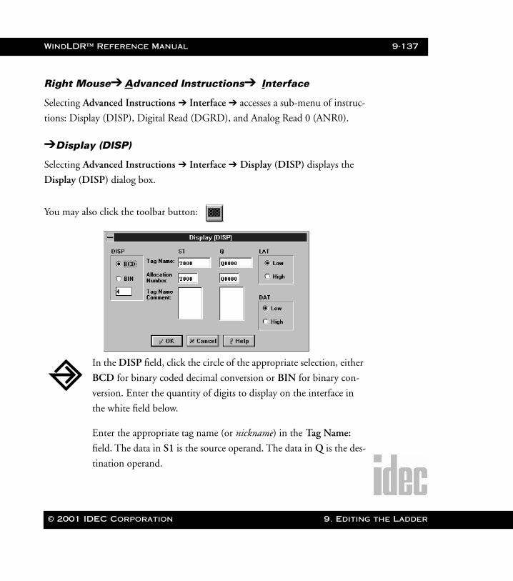
WindLDR™ Reference Manual 9-137
WLDR ReferenceBook Page 137 Thursday, April 5, 2001 3:36 PM
Right Mouse➔ Advanced Instructions➔ Interface
Selecting Advanced Instructions ➔ Interface ➔ accesses a sub-menu of instruc-
tions: Display (DISP), Digital Read (DGRD), and Analog Read 0 (ANR0).
➔Display (DISP)
Selecting Advanced Instructions ➔ Interface ➔ Display (DISP) displays the
Display (DISP) dialog box.
You may also click the toolbar button:
In the DISP field, click the circle of the appropriate selection, either
BCD for binary coded decimal conversion or BIN for binary con-
version. Enter the quantity of digits to display on the interface in
the white field below.
Enter the appropriate tag name (or nickname) in the Tag Name:
field. The data in S1 is the source operand. The data in Q is the des-
tination operand.
© 2001 IDEC Corporation 9. Editing the Ladder
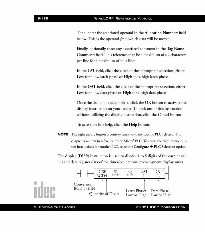
9-138 WindLDR™ Reference Manual
9. Editing t
WLDR ReferenceBook Page 138 Thursday, April 5, 2001 3:36 PM
Then, enter the associated operand in the Allocation Number: field
below. This is the operand from which data will be moved.
Finally, optionally enter any associated comment in the Tag Name
Comment: field. This reference may be a maximum of six characters
per line for a maximum of four lines.
In the LAT field, click the circle of the appropriate selection, either
Low for a low latch phase or High for a high latch phase.
In the DAT field, click the circle of the appropriate selection, either
Low for a low data phase or High for a high data phase.
Once the dialog box is complete, click the OK button to activate the
display instruction on your ladder. To back out of this instruction
without utilizing the display instruction, click the Cancel button.
To access on-line help, click the Help button.
NOTE: The right mouse button is context-sensitive to the specific PLC selected. This
chapter is written in reference to the Micro3 PLC. To access the right mouse but-
ton instructions for another PLC, select the Configure ➔ PLC Selection option.
The display (DISP) instruction is used to display 1 to 5 digits of the current val-
ues and data register data of the timer/counter on seven-segment display units.
DISP S1 LAT DAT***** L L
Q****BCD4
Conversion:BCD or BIN
Quantity of DigitsLatch Phase:Low or High
Data Phase:Low or High
he Ladder © 2001 IDEC Corporation
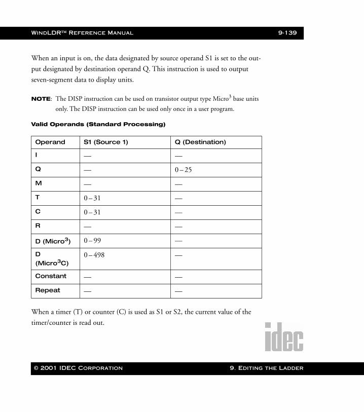
WindLDR™ Reference Manual 9-139
WLDR ReferenceBook Page 139 Thursday, April 5, 2001 3:36 PM
When an input is on, the data designated by source operand S1 is set to the out-
put designated by destination operand Q. This instruction is used to output
seven-segment data to display units.
NOTE: The DISP instruction can be used on transistor output type Micro3 base units
only. The DISP instruction can be used only once in a user program.
Valid Operands (Standard Processing)
When a timer (T) or counter (C) is used as S1 or S2, the current value of the
timer/counter is read out.
Operand S1 (Source 1) Q (Destination)
I — —
Q — 0 – 25
M — —
T 0 – 31 —
C 0 – 31 —
R — —
D (Micro3) 0 – 99 —
D (Micro3C)
0 – 498 —
Constant — —
Repeat — —
© 2001 IDEC Corporation 9. Editing the Ladder
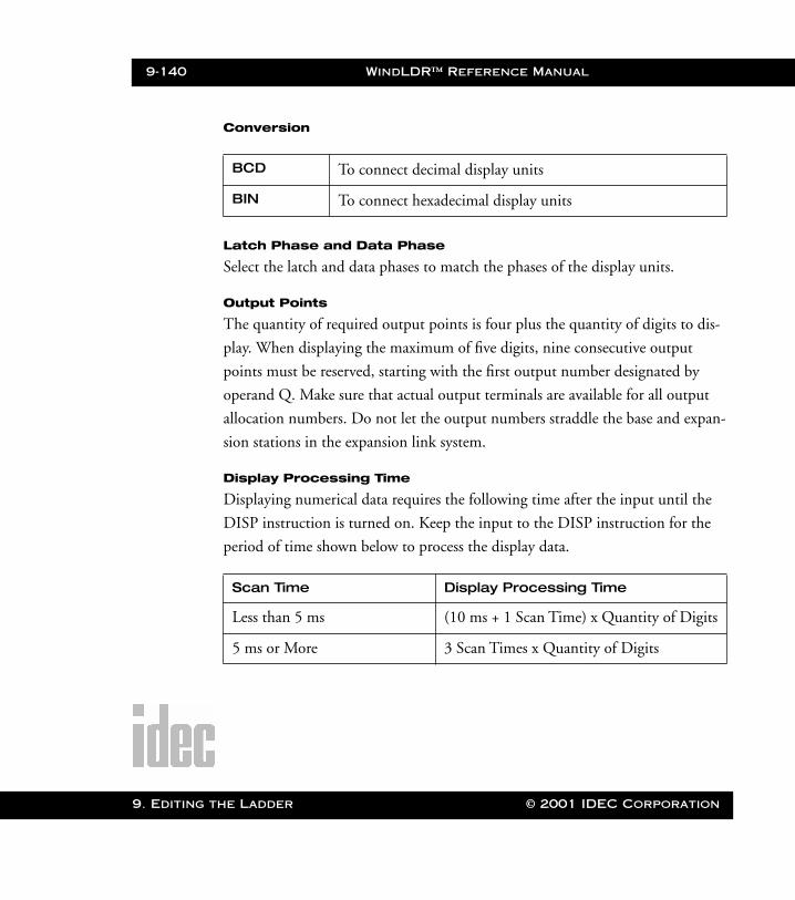
9-140 WindLDR™ Reference Manual
9. Editing t
WLDR ReferenceBook Page 140 Thursday, April 5, 2001 3:36 PM
Conversion
Latch Phase and Data Phase
Select the latch and data phases to match the phases of the display units.
Output Points
The quantity of required output points is four plus the quantity of digits to dis-
play. When displaying the maximum of five digits, nine consecutive output
points must be reserved, starting with the first output number designated by
operand Q. Make sure that actual output terminals are available for all output
allocation numbers. Do not let the output numbers straddle the base and expan-
sion stations in the expansion link system.
Display Processing Time
Displaying numerical data requires the following time after the input until the
DISP instruction is turned on. Keep the input to the DISP instruction for the
period of time shown below to process the display data.
BCD To connect decimal display units
BIN To connect hexadecimal display units
Scan Time Display Processing Time
Less than 5 ms (10 ms + 1 Scan Time) x Quantity of Digits
5 ms or More 3 Scan Times x Quantity of Digits
he Ladder © 2001 IDEC Corporation
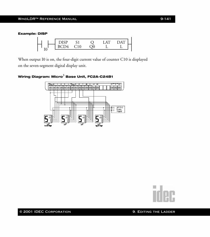
WindLDR™ Reference Manual 9-141
WLDR ReferenceBook Page 141 Thursday, April 5, 2001 3:36 PM
Example: DISP
When output I0 is on, the four-digit current value of counter C10 is displayed
on the seven-segment digital display unit.
Wiring Diagram: Micro3 Base Unit, FC2A-C24B1
I0
DISP S1 LAT DATC10 L L
QQ0BCD4
© 2001 IDEC Corporation 9. Editing the Ladder
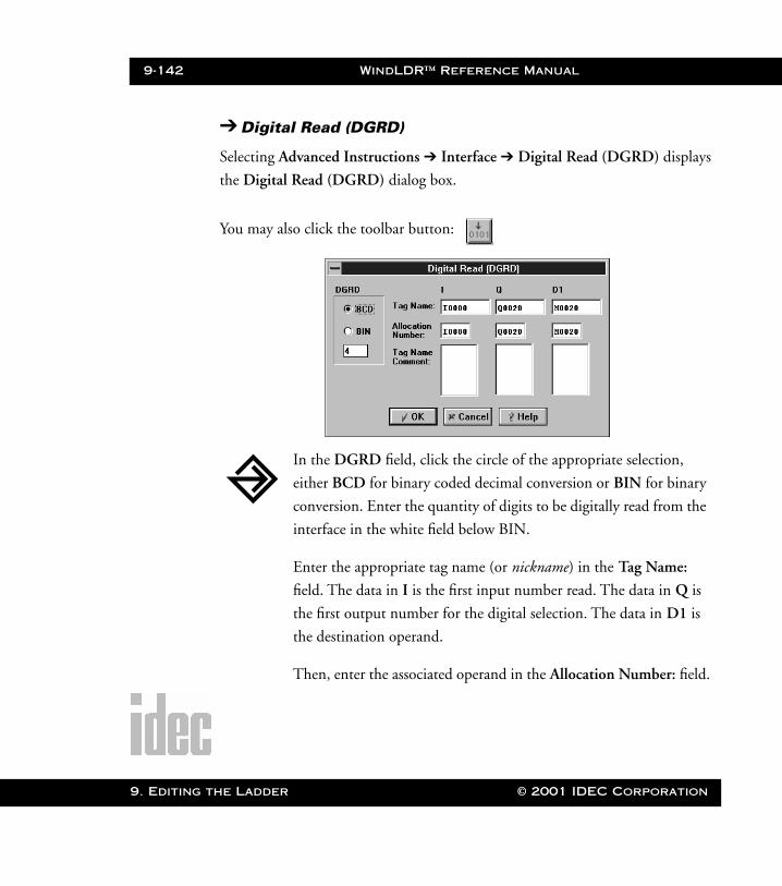
9-142 WindLDR™ Reference Manual
9. Editing t
WLDR ReferenceBook Page 142 Thursday, April 5, 2001 3:36 PM
➔ Digital Read (DGRD)
Selecting Advanced Instructions ➔ Interface ➔ Digital Read (DGRD) displays
the Digital Read (DGRD) dialog box.
You may also click the toolbar button:
In the DGRD field, click the circle of the appropriate selection,
either BCD for binary coded decimal conversion or BIN for binary
conversion. Enter the quantity of digits to be digitally read from the
interface in the white field below BIN.
Enter the appropriate tag name (or nickname) in the Tag Name:
field. The data in I is the first input number read. The data in Q is
the first output number for the digital selection. The data in D1 is
the destination operand.
Then, enter the associated operand in the Allocation Number: field.
he Ladder © 2001 IDEC Corporation
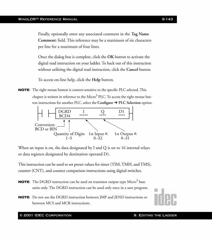
WindLDR™ Reference Manual 9-143
WLDR ReferenceBook Page 143 Thursday, April 5, 2001 3:36 PM
Finally, optionally enter any associated comment in the Tag Name
Comment: field. This reference may be a maximum of six characters
per line for a maximum of four lines.
Once the dialog box is complete, click the OK button to activate the
digital read instruction on your ladder. To back out of this instruction
without utilizing the digital read instruction, click the Cancel button.
To access on-line help, click the Help button.
NOTE: The right mouse button is context-sensitive to the specific PLC selected. This
chapter is written in reference to the Micro3 PLC. To access the right mouse but-
ton instructions for another PLC, select the Configure ➔ PLC Selection option.
When an input is on, the data designated by I and Q is set to 16 internal relays
or data registers designated by destination operand D1.
This instruction can be used to set preset values for timer (TIM, TMH, and TMS),
counter (CNT), and counter comparison instructions using digital switches.
NOTE: The DGRD instruction can be used on transistor output type Micro3 base
units only. The DGRD instruction can be used only once in a user program.
NOTE: Do not use the DGRD instruction between JMP and JEND instructions or
between MCS and MCR instructions.
DGRD I D1***** ****
Q****BCD4
Conversion:BCD or BIN
Quantity of Digits 1st Input #:0–32
1st Output #:0–311–5
© 2001 IDEC Corporation 9. Editing the Ladder
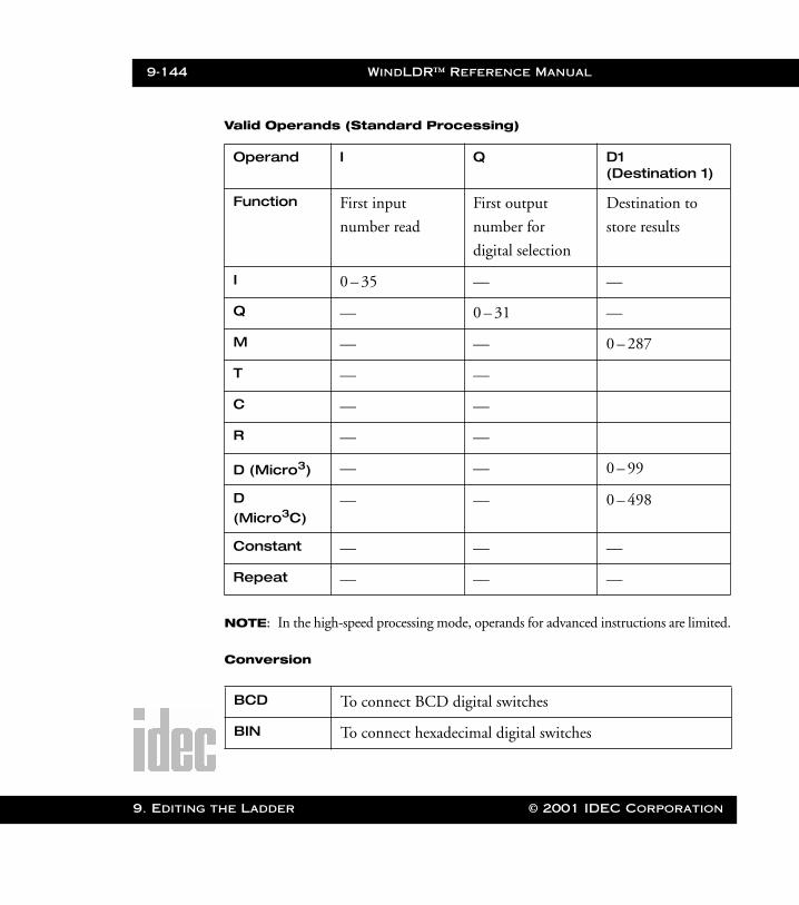
9-144 WindLDR™ Reference Manual
9. Editing t
WLDR ReferenceBook Page 144 Thursday, April 5, 2001 3:36 PM
Valid Operands (Standard Processing)
NOTE: In the high-speed processing mode, operands for advanced instructions are limited.
Conversion
Operand I Q D1 (Destination 1)
Function First input
number read
First output
number for
digital selection
Destination to
store results
I 0 – 35 — —
Q — 0 – 31 —
M — — 0 – 287
T — —
C — —
R — —
D (Micro3) — — 0 – 99
D (Micro3C)
— — 0 – 498
Constant — — —
Repeat — — —
BCD To connect BCD digital switches
BIN To connect hexadecimal digital switches
he Ladder © 2001 IDEC Corporation
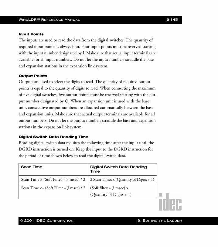
WindLDR™ Reference Manual 9-145
WLDR ReferenceBook Page 145 Thursday, April 5, 2001 3:36 PM
Input Points
The inputs are used to read the data from the digital switches. The quantity of
required input points is always four. Four input points must be reserved starting
with the input number designated by I. Make sure that actual input terminals are
available for all input numbers. Do not let the input numbers straddle the base
and expansion stations in the expansion link system.
Output Points
Outputs are used to select the digits to read. The quantity of required output
points is equal to the quantity of digits to read. When connecting the maximum
of five digital switches, five output points must be reserved starting with the out-
put number designated by Q. When an expansion unit is used with the base
unit, consecutive output numbers are allocated automatically between the base
and expansion units. Make sure that actual output terminals are available for all
output numbers. Do not let the output numbers straddle the base and expansion
stations in the expansion link system.
Digital Switch Data Reading Time
Reading digital switch data requires the following time after the input until the
DGRD instruction is turned on. Keep the input to the DGRD instruction for
the period of time shown below to read the digital switch data.
Scan Time Digital Switch Data Reading Time
Scan Time > (Soft Filter + 3 msec) / 2 2 Scan Times x (Quantity of Digits + 1)
Scan Time <= (Soft Filter + 3 msec) / 2 (Soft filter + 3 msec) x
(Quantity of Digits + 1)
© 2001 IDEC Corporation 9. Editing the Ladder

9-146 WindLDR™ Reference Manual
9. Editing t
WLDR ReferenceBook Page 146 Thursday, April 5, 2001 3:36 PM
The following example demonstrates a program to read data from four digital
switches to a data register in the 16-point transistor sink output type Micro3 or
Micro3C base unit.
Example: DGRD
When input I5 is on, the four-digit value from BCD digital switches is read to
data register D10.
➔ Analog Read 0 (ANR0)
Selecting Advanced Instructions ➔ Interface ➔ Analog Read 0 (ANR0) displays
the Analog Read 0 (ANR0) dialog box.
You may also click the toolbar button:
I5
DGRD I D1I0 D10
QQ0BCD4
he Ladder © 2001 IDEC Corporation

WindLDR™ Reference Manual 9-147
WLDR ReferenceBook Page 147 Thursday, April 5, 2001 3:36 PM
NOTE: The right mouse button is context-sensitive to the specific PLC selected. This
chapter is written in reference to the Micro3 PLC. To access the right mouse but-
ton instructions for another PLC, select the Configure ➔ PLC Selection option.
When an input is on, the value (0–249) set with analog potentiometer 0 is read
to the data register designated as the destination.
This instruction is useful for adjusting the preset values of timer (TIM, TMH,
and TMS) and pulse (PULS and PWM) instructions.
The Analog Read 0 option in the Type: field remains selected.
Enter the tag name (or nickname) in the Tag Name: field. Then,
enter the associated operand in the Allocation Number: field. This
is the operand used to read to the data register designated as the des-
tination.
Finally, optionally enter any associated comment in the Tag Name
Comment: field. This reference may be a maximum of six characters
per line for a maximum of four lines.
Once the dialog box is complete, click the OK button to activate the
analog instruction on your ladder. To back out of this instruction
without utilizing the analog instruction, click the Cancel button.
To access on-line help, click the Help button.
ANR0*****
© 2001 IDEC Corporation 9. Editing the Ladder
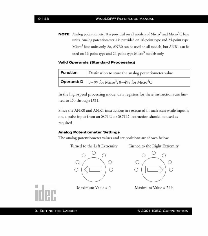
9-148 WindLDR™ Reference Manual
9. Editing t
WLDR ReferenceBook Page 148 Thursday, April 5, 2001 3:36 PM
NOTE: Analog potentiometer 0 is provided on all models of Micro3 and Micro3C base
units. Analog potentiometer 1 is provided on 16-point type and 24-point type
Micro3 base units only. So, ANR0 can be used on all models, but ANR1 can be
used on 16-point type and 24-point type Micro3 models only.
Valid Operands (Standard Processing)
In the high-speed processing mode, data registers for these instructions are lim-
ited to D0 through D31.
Since the ANR0 and ANR1 instructions are executed in each scan while input is
on, a pulse input from an SOTU or SOTD instruction should be used as
required.
Analog Potentiometer Settings
The analog potentiometer values and set positions are shown below.
Function Destination to store the analog potentiometer value
Operand: D 0 – 99 for Micro3; 0–498 for Micro3C
Turned to the Left Extremity
Maximum Value = 0
Turned to the Right Extremity
Maximum Value = 249
he Ladder © 2001 IDEC Corporation
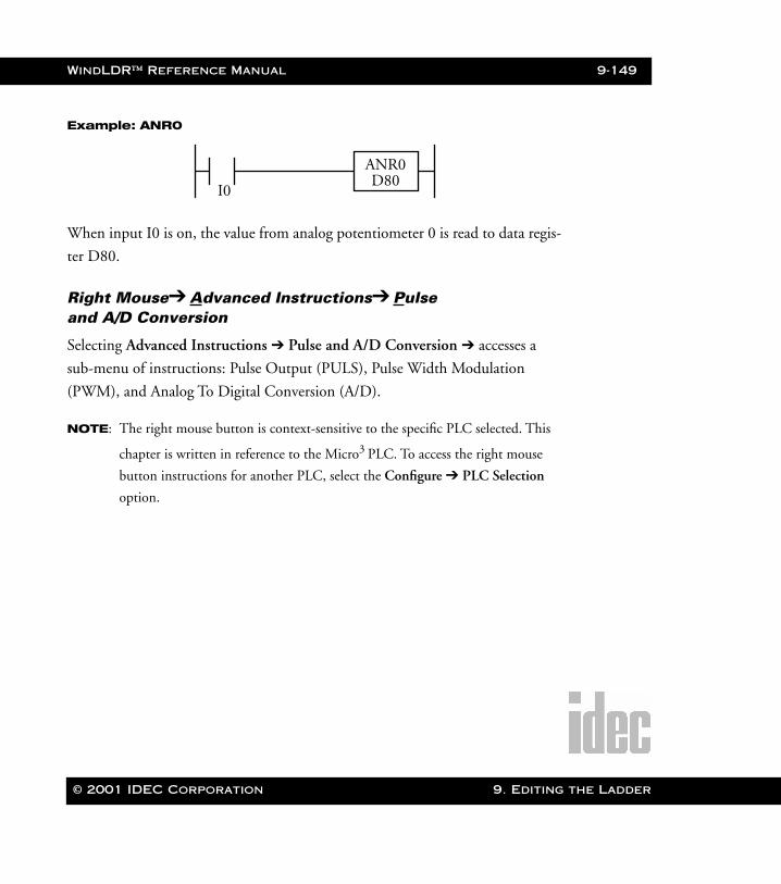
WindLDR™ Reference Manual 9-149
WLDR ReferenceBook Page 149 Thursday, April 5, 2001 3:36 PM
Example: ANR0
When input I0 is on, the value from analog potentiometer 0 is read to data regis-
ter D80.
Right Mouse➔ Advanced Instructions➔ Pulseand A/D Conversion
Selecting Advanced Instructions ➔ Pulse and A/D Conversion ➔ accesses a
sub-menu of instructions: Pulse Output (PULS), Pulse Width Modulation
(PWM), and Analog To Digital Conversion (A/D).
NOTE: The right mouse button is context-sensitive to the specific PLC selected. This
chapter is written in reference to the Micro3 PLC. To access the right mouse
button instructions for another PLC, select the Configure ➔ PLC Selection
option.
I0
ANR0D80
© 2001 IDEC Corporation 9. Editing the Ladder
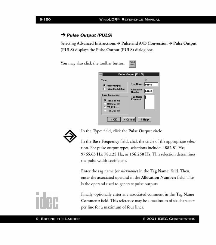
9-150 WindLDR™ Reference Manual
9. Editing t
WLDR ReferenceBook Page 150 Thursday, April 5, 2001 3:36 PM
➔ Pulse Output (PULS)
Selecting Advanced Instructions ➔ Pulse and A/D Conversion ➔ Pulse Output
(PULS) displays the Pulse Output (PULS) dialog box.
You may also click the toolbar button:
In the Type: field, click the Pulse Output circle.
In the Base Frequency field, click the circle of the appropriate selec-
tion. For pulse output types, selections include: 4882.81 Hz;
9765.63 Hz; 78,125 Hz; or 156,250 Hz. This selection determines
the pulse width coefficient.
Enter the tag name (or nickname) in the Tag Name: field. Then,
enter the associated operand in the Allocation Number: field. This
is the operand used to generate pulse outputs.
Finally, optionally enter any associated comment in the Tag Name
Comment: field. This reference may be a maximum of six characters
per line for a maximum of four lines.
he Ladder © 2001 IDEC Corporation
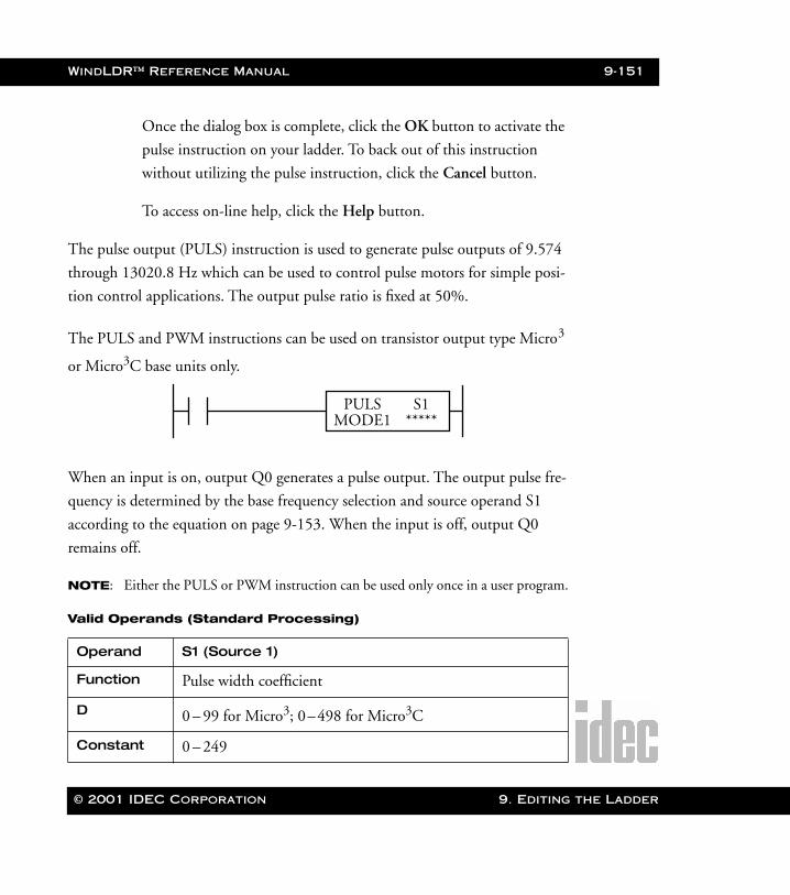
WindLDR™ Reference Manual 9-151
WLDR ReferenceBook Page 151 Thursday, April 5, 2001 3:36 PM
Once the dialog box is complete, click the OK button to activate the
pulse instruction on your ladder. To back out of this instruction
without utilizing the pulse instruction, click the Cancel button.
To access on-line help, click the Help button.
The pulse output (PULS) instruction is used to generate pulse outputs of 9.574
through 13020.8 Hz which can be used to control pulse motors for simple posi-
tion control applications. The output pulse ratio is fixed at 50%.
The PULS and PWM instructions can be used on transistor output type Micro3
or Micro3C base units only.
When an input is on, output Q0 generates a pulse output. The output pulse fre-
quency is determined by the base frequency selection and source operand S1
according to the equation on page 9-153. When the input is off, output Q0
remains off.
NOTE: Either the PULS or PWM instruction can be used only once in a user program.
Valid Operands (Standard Processing)
Operand S1 (Source 1)
Function Pulse width coefficient
D 0 – 99 for Micro3; 0–498 for Micro3C
Constant 0 – 249
PULS S1*****MODE1
© 2001 IDEC Corporation 9. Editing the Ladder
9-152 WindLDR™ Reference Manual
9. Editing t
WLDR ReferenceBook Page 152 Thursday, April 5, 2001 3:36 PM
While the Micro3 base unit is running, the base frequency selection cannot be
changed. To change the output pulse frequency during operation, use a data reg-
ister as source operand S1 and change the value of the data register.
When a data register is designated as S1, make sure that the value of the data reg-
ister does not exceed 249. If the value of the data register designated as S1
exceeds 249 during operation, then a user program execution error will occur.
Then the ERR1 indicator on the Micro3 base unit is lit, and special internal relay
M304 is also turned on. Correct the program, and transfer the corrected pro-
gram to the Micro3 base unit.
When a data register is designated as S1, the data is read as the user program is
scanned. When changing the value of the data register designated as S1, change
the value slowly in comparison to the output frequency.
When Q0 is monitored while the PULS instruction is executed, Q0 remains on
and the output indicator also remains on. When input to the PULS instruction
is turned off while the pulse output is on, the output is turned off after a com-
plete pulse is generated.
Output Frequency
WindLDR displays MODE1 through MODE4 on the ladder. However, when
selecting the base frequency in the dialog box, the actual frequencies are dis-
played, not the MODE.
he Ladder © 2001 IDEC Corporation

WindLDR™ Reference Manual 9-153
WLDR ReferenceBook Page 153 Thursday, April 5, 2001 3:36 PM
The output frequency is determined by the following equation.
MODE Base Frequency
Frequency Range (Coefficient 249 through 0)
MODE1 4882.81 Hz 9.574 through 406.901 Hz
MODE2 9765.63 Hz 19.148 through 813.802 Hz
MODE3 78,125 Hz 153.186 through 6510.42 Hz
MODE4 156,250 Hz 306.373 through 13020.8 Hz
Output Frequency =Base Frequency (MODE)
(Pulse Width Coefficient S1 + 6) x 2[Hz]
Pulse Width Coefficient S1 =Base Frequency (MODE)
Output Frequency x 2– 6
Period = 1Frequency
© 2001 IDEC Corporation 9. Editing the Ladder
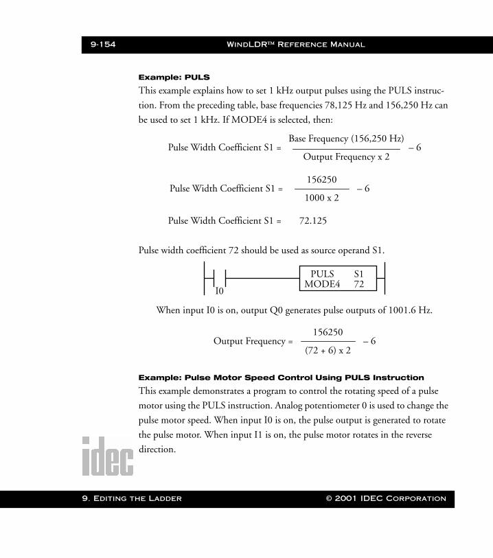
9-154 WindLDR™ Reference Manual
9. Editing t
WLDR ReferenceBook Page 154 Thursday, April 5, 2001 3:36 PM
Example: PULS
This example explains how to set 1 kHz output pulses using the PULS instruc-
tion. From the preceding table, base frequencies 78,125 Hz and 156,250 Hz can
be used to set 1 kHz. If MODE4 is selected, then:
Pulse width coefficient 72 should be used as source operand S1.
Example: Pulse Motor Speed Control Using PULS Instruction
This example demonstrates a program to control the rotating speed of a pulse
motor using the PULS instruction. Analog potentiometer 0 is used to change the
pulse motor speed. When input I0 is on, the pulse output is generated to rotate
the pulse motor. When input I1 is on, the pulse motor rotates in the reverse
direction.
Pulse Width Coefficient S1 =Base Frequency (156,250 Hz)
Output Frequency x 2– 6
Pulse Width Coefficient S1 =156250
1000 x 2– 6
Pulse Width Coefficient S1 = 72.125
I0
PULS S172MODE4
When input I0 is on, output Q0 generates pulse outputs of 1001.6 Hz.
Output Frequency =156250
(72 + 6) x 2– 6
he Ladder © 2001 IDEC Corporation
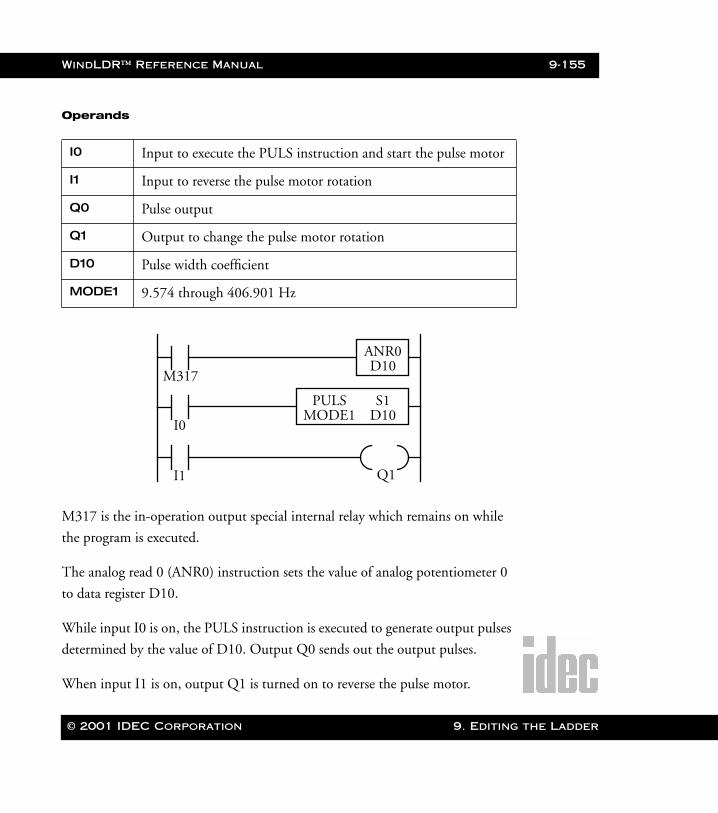
WindLDR™ Reference Manual 9-155
WLDR ReferenceBook Page 155 Thursday, April 5, 2001 3:36 PM
Operands
M317 is the in-operation output special internal relay which remains on while
the program is executed.
The analog read 0 (ANR0) instruction sets the value of analog potentiometer 0
to data register D10.
While input I0 is on, the PULS instruction is executed to generate output pulses
determined by the value of D10. Output Q0 sends out the output pulses.
When input I1 is on, output Q1 is turned on to reverse the pulse motor.
I0 Input to execute the PULS instruction and start the pulse motor
I1 Input to reverse the pulse motor rotation
Q0 Pulse output
Q1 Output to change the pulse motor rotation
D10 Pulse width coefficient
MODE1 9.574 through 406.901 Hz
M317
ANR0D10
I0
PULS S1D10MODE1
I1 Q1
© 2001 IDEC Corporation 9. Editing the Ladder
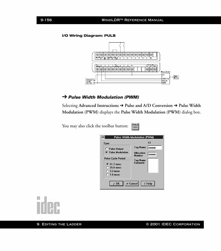
9-156 WindLDR™ Reference Manual
9. Editing t
WLDR ReferenceBook Page 156 Thursday, April 5, 2001 3:36 PM
I/O Wiring Diagram: PULS
➔ Pulse Width Modulation (PWM)
Selecting Advanced Instructions ➔ Pulse and A/D Conversion ➔ Pulse Width
Modulation (PWM) displays the Pulse Width Modulation (PWM) dialog box.
You may also click the toolbar button:
he Ladder © 2001 IDEC Corporation
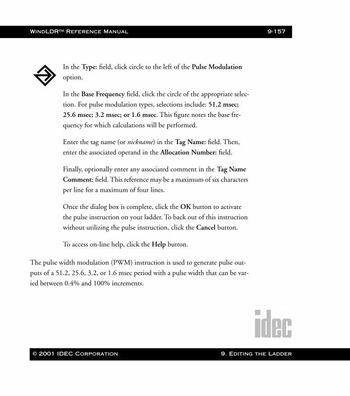
WindLDR™ Reference Manual 9-157
WLDR ReferenceBook Page 157 Thursday, April 5, 2001 3:36 PM
The pulse width modulation (PWM) instruction is used to generate pulse out-
puts of a 51.2, 25.6, 3.2, or 1.6 msec period with a pulse width that can be var-
ied between 0.4% and 100% increments.
In the Type: field, click circle to the left of the Pulse Modulation
option.
In the Base Frequency field, click the circle of the appropriate selec-
tion. For pulse modulation types, selections include: 51.2 msec;
25.6 msec; 3.2 msec; or 1.6 msec. This figure notes the base fre-
quency for which calculations will be performed.
Enter the tag name (or nickname) in the Tag Name: field. Then,
enter the associated operand in the Allocation Number: field.
Finally, optionally enter any associated comment in the Tag Name
Comment: field. This reference may be a maximum of six characters
per line for a maximum of four lines.
Once the dialog box is complete, click the OK button to activate
the pulse instruction on your ladder. To back out of this instruction
without utilizing the pulse instruction, click the Cancel button.
To access on-line help, click the Help button.
© 2001 IDEC Corporation 9. Editing the Ladder
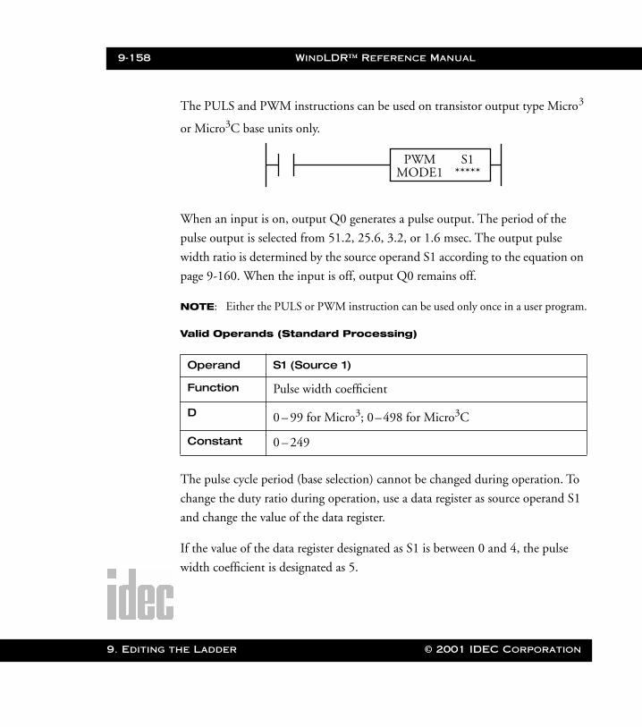
9-158 WindLDR™ Reference Manual
9. Editing t
WLDR ReferenceBook Page 158 Thursday, April 5, 2001 3:36 PM
The PULS and PWM instructions can be used on transistor output type Micro3
or Micro3C base units only.
When an input is on, output Q0 generates a pulse output. The period of the
pulse output is selected from 51.2, 25.6, 3.2, or 1.6 msec. The output pulse
width ratio is determined by the source operand S1 according to the equation on
page 9-160. When the input is off, output Q0 remains off.
NOTE: Either the PULS or PWM instruction can be used only once in a user program.
Valid Operands (Standard Processing)
The pulse cycle period (base selection) cannot be changed during operation. To
change the duty ratio during operation, use a data register as source operand S1
and change the value of the data register.
If the value of the data register designated as S1 is between 0 and 4, the pulse
width coefficient is designated as 5.
Operand S1 (Source 1)
Function Pulse width coefficient
D 0 – 99 for Micro3; 0–498 for Micro3C
Constant 0 – 249
PWM S1*****MODE1
he Ladder © 2001 IDEC Corporation
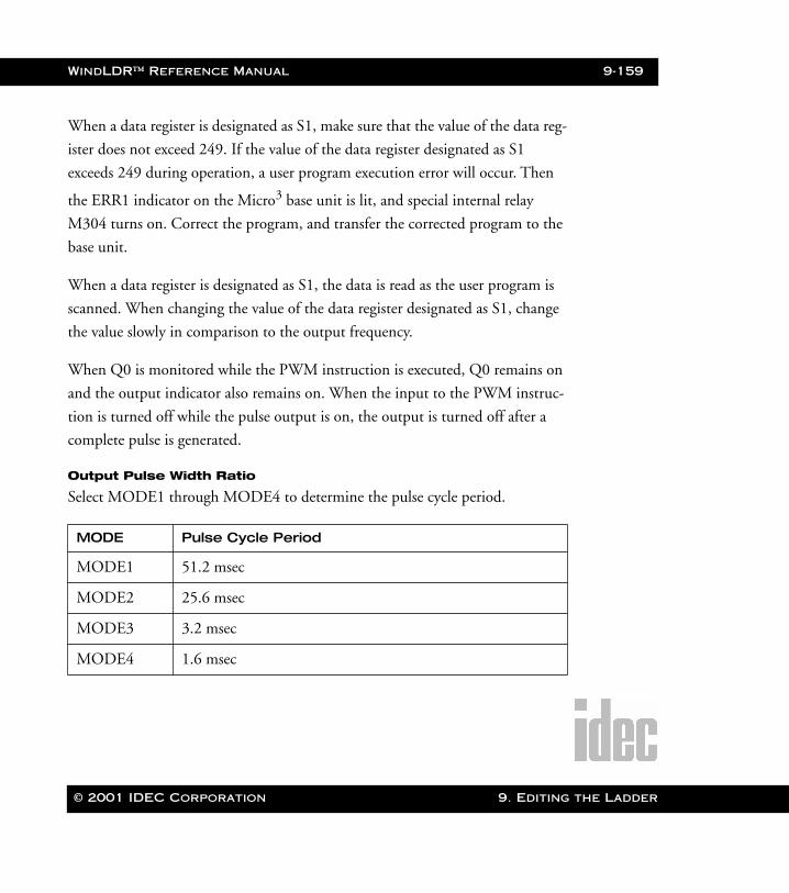
WindLDR™ Reference Manual 9-159
WLDR ReferenceBook Page 159 Thursday, April 5, 2001 3:36 PM
When a data register is designated as S1, make sure that the value of the data reg-
ister does not exceed 249. If the value of the data register designated as S1
exceeds 249 during operation, a user program execution error will occur. Then
the ERR1 indicator on the Micro3 base unit is lit, and special internal relay
M304 turns on. Correct the program, and transfer the corrected program to the
base unit.
When a data register is designated as S1, the data is read as the user program is
scanned. When changing the value of the data register designated as S1, change
the value slowly in comparison to the output frequency.
When Q0 is monitored while the PWM instruction is executed, Q0 remains on
and the output indicator also remains on. When the input to the PWM instruc-
tion is turned off while the pulse output is on, the output is turned off after a
complete pulse is generated.
Output Pulse Width Ratio
Select MODE1 through MODE4 to determine the pulse cycle period.
MODE Pulse Cycle Period
MODE1 51.2 msec
MODE2 25.6 msec
MODE3 3.2 msec
MODE4 1.6 msec
© 2001 IDEC Corporation 9. Editing the Ladder
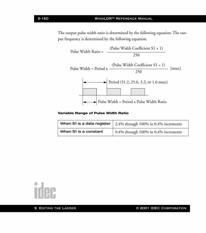
9-160 WindLDR™ Reference Manual
9. Editing t
WLDR ReferenceBook Page 160 Thursday, April 5, 2001 3:36 PM
The output pulse width ratio is determined by the following equation. The out-
put frequency is determined by the following equation.
Variable Range of Pulse Width Ratio
When S1 is a data register 2.4% through 100% in 0.4% increments
When S1 is a constant 0.4% through 100% in 0.4% increments
Pulse Width Ratio =250
(Pulse Width Coefficient S1 + 1)
Pulse Width = Period x
Period (51.2, 25.6, 3.2, or 1.6 msec)
Pulse Width = Period x Pulse Width Ratio
250
(Pulse Width Coefficient S1 + 1)[msec]
he Ladder © 2001 IDEC Corporation
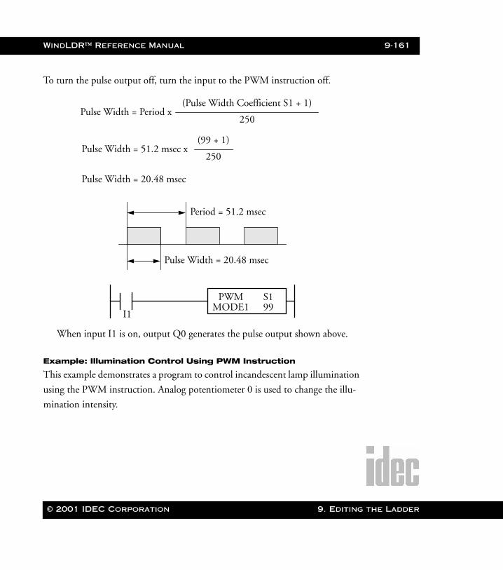
WindLDR™ Reference Manual 9-161
WLDR ReferenceBook Page 161 Thursday, April 5, 2001 3:36 PM
To turn the pulse output off, turn the input to the PWM instruction off.
Example: Illumination Control Using PWM Instruction
This example demonstrates a program to control incandescent lamp illumination
using the PWM instruction. Analog potentiometer 0 is used to change the illu-
mination intensity.
Pulse Width = Period x
Period = 51.2 msec
Pulse Width = 20.48 msec
250
(Pulse Width Coefficient S1 + 1)
Pulse Width = 51.2 msec x250
(99 + 1)
Pulse Width = 20.48 msec
I1
PWM S199MODE1
When input I1 is on, output Q0 generates the pulse output shown above.
© 2001 IDEC Corporation 9. Editing the Ladder
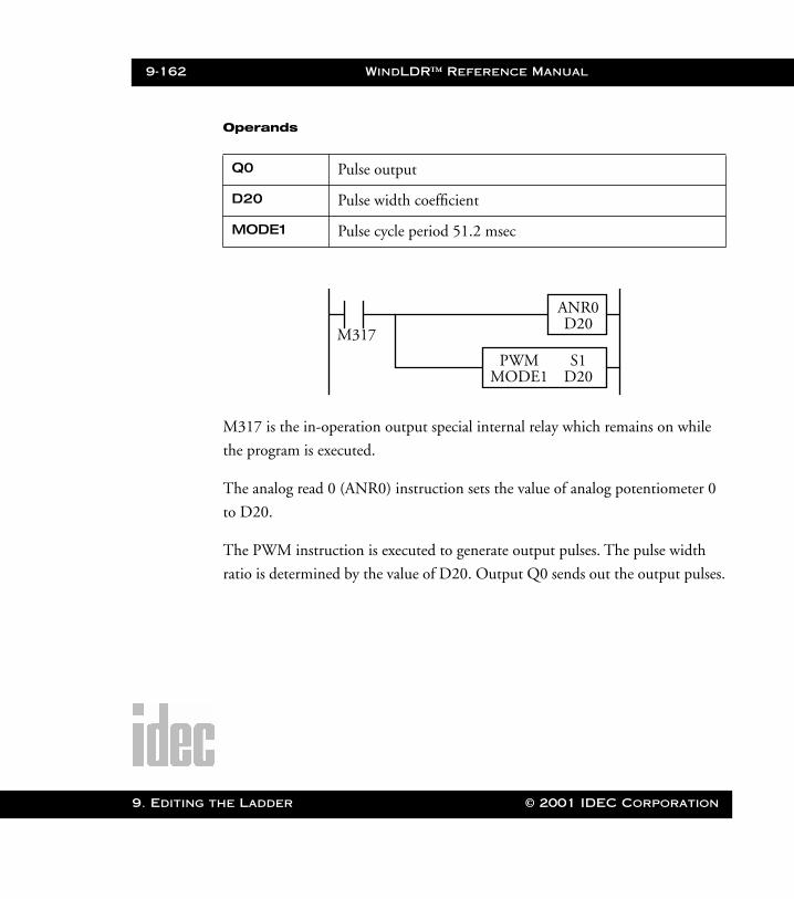
9-162 WindLDR™ Reference Manual
9. Editing t
WLDR ReferenceBook Page 162 Thursday, April 5, 2001 3:36 PM
Operands
M317 is the in-operation output special internal relay which remains on while
the program is executed.
The analog read 0 (ANR0) instruction sets the value of analog potentiometer 0
to D20.
The PWM instruction is executed to generate output pulses. The pulse width
ratio is determined by the value of D20. Output Q0 sends out the output pulses.
Q0 Pulse output
D20 Pulse width coefficient
MODE1 Pulse cycle period 51.2 msec
M317
ANR0D20
PWM S1D20MODE1
he Ladder © 2001 IDEC Corporation

WindLDR™ Reference Manual 9-163
WLDR ReferenceBook Page 163 Thursday, April 5, 2001 3:36 PM
➔ Analog To Digital Conversion (A/D)
Selecting Advanced Instructions ➔ Pulse and A/D Conversion ➔ Analog To
Digital Conversion (A/D) displays the Analog To Digital Conversion (A/D)
dialog box.
You may also click the toolbar button:
In the Digital Data Range field, click the circle of the appropriate
selection, either 8 bits or 12 bits. This figure notes the analog to
digital resolution.
Enter the tag name (or nickname) in the Tag Name: field. Then,
enter the associated operand in the Allocation Number: field below.
This operand indicates the destination of the data conversion.
Finally, optionally enter any associated comment in the Tag Name
Comment: field. This reference may be a maximum of six characters
per line for a maximum of four lines.
© 2001 IDEC Corporation 9. Editing the Ladder
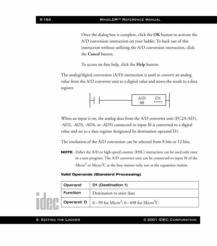
9-164 WindLDR™ Reference Manual
9. Editing t
WLDR ReferenceBook Page 164 Thursday, April 5, 2001 3:36 PM
Once the dialog box is complete, click the OK button to activate the
A/D conversion instruction on your ladder. To back out of this
instruction without utilizing the A/D conversion instruction, click
the Cancel button.
To access on-line help, click the Help button.
The analog/digital conversion (A/D) instruction is used to convert an analog
value from the A/D converter unit to a digital value and stores the result to a data
register.
When an input is on, the analog data from the A/D converter unit (FC2A-AD1,
-AD2, -AD3, -AD4, or -AD5) connected to input I0 is converted to a digital
value and set to a data register designated by destination operand D1.
The resolution of the A/D conversion can be selected from 8 bits or 12 bits.
NOTE: Either the A/D or high-speed counter (HSC) instruction can be used only once
in a user program. The A/D converter unit can be connected to input I0 of the
Micro3 or Micro3C at the base station only, not at the expansion station.
Valid Operands (Standard Processing)
Operand D1 (Destination 1)
Function Destination to store data
Operand: D 0 – 99 for Micro3; 0–498 for Micro3C
A/D D1*****08
he Ladder © 2001 IDEC Corporation
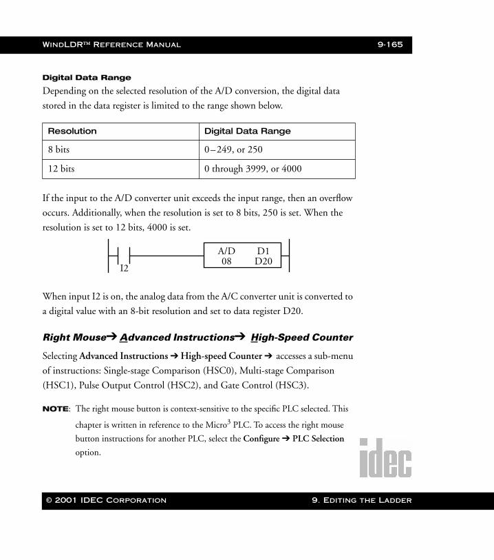
WindLDR™ Reference Manual 9-165
WLDR ReferenceBook Page 165 Thursday, April 5, 2001 3:36 PM
Digital Data Range
Depending on the selected resolution of the A/D conversion, the digital data
stored in the data register is limited to the range shown below.
If the input to the A/D converter unit exceeds the input range, then an overflow
occurs. Additionally, when the resolution is set to 8 bits, 250 is set. When the
resolution is set to 12 bits, 4000 is set.
When input I2 is on, the analog data from the A/C converter unit is converted to
a digital value with an 8-bit resolution and set to data register D20.
Right Mouse➔ Advanced Instructions➔ High-Speed Counter
Selecting Advanced Instructions ➔ High-speed Counter ➔ accesses a sub-menu
of instructions: Single-stage Comparison (HSC0), Multi-stage Comparison
(HSC1), Pulse Output Control (HSC2), and Gate Control (HSC3).
NOTE: The right mouse button is context-sensitive to the specific PLC selected. This
chapter is written in reference to the Micro3 PLC. To access the right mouse
button instructions for another PLC, select the Configure ➔ PLC Selection
option.
Resolution Digital Data Range
8 bits 0–249, or 250
12 bits 0 through 3999, or 4000
I2
A/D D1D2008
© 2001 IDEC Corporation 9. Editing the Ladder
9-166 WindLDR™ Reference Manual
9. Editing t
WLDR ReferenceBook Page 166 Thursday, April 5, 2001 3:36 PM
Introduction to Counters
The Micro3 and Micro3C feature high-speed counter functions which can be
used for position control by counting high-speed pulses or for simple motor con-
trol in combination with the pulse output. This function can also be used in
combination with a pulse generator to measure lengths or widths of objects.
The ordinary counter instruction counts only one pulse in one scan, and the
counting speed depends on the scan time. The high-speed counter can count
many input pulses in one scan and make it possible to count high-speed pulses
faster than the scan time. If the high-speed counter counts input pulses repre-
senting a position, the current position can be determined. This function is use-
ful for position control.
The HSC0 is a high-speed counter with a single-stage comparison function.
When the current value is equal to or greater than the preset value
(4,294,967,295 maximum), a designated output or internal relay is turned on.
The HSC1 is a multi-stage comparison counter. The preset value and output
data is programmed in data registers. When a preset value is reached
(4,294,967,295 maximum), a designated output or internal relay is turned on.
The HSC2 is a pulse output control counter used with the PULS (pulse output)
instruction. When a preset value is reached, a designated output or internal relay
is turned on and output pulses at output Q0 is turned off.
The HSC3 is a gate-controlled counter without a comparison function. When the
gate input is turned off, the current value is moved to a designated data register.
he Ladder © 2001 IDEC Corporation
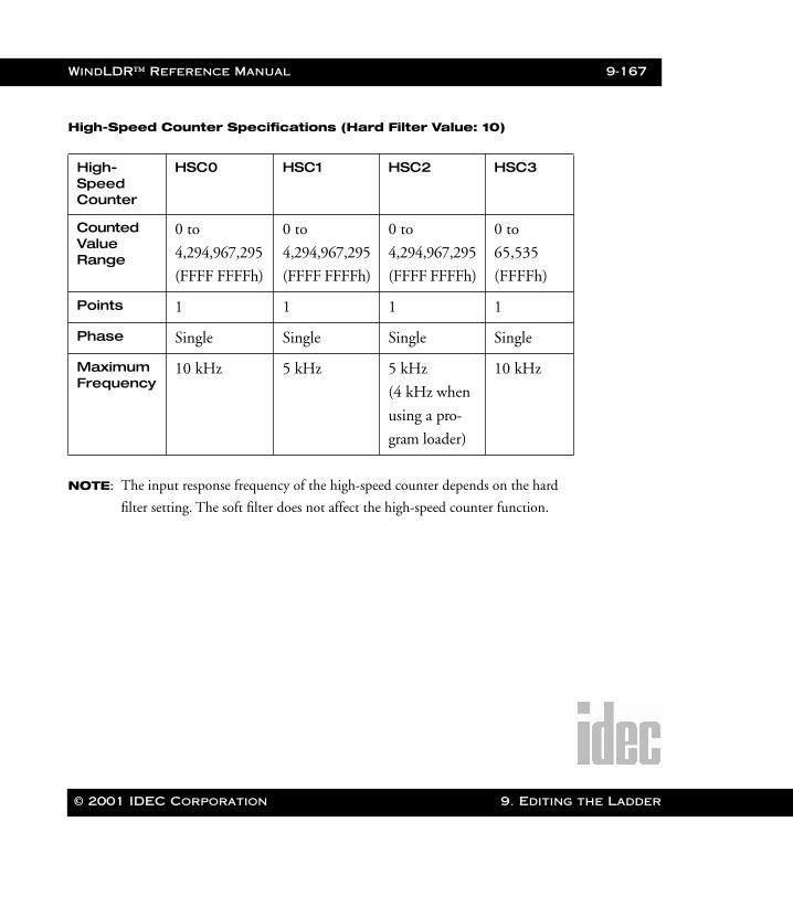
WindLDR™ Reference Manual 9-167
WLDR ReferenceBook Page 167 Thursday, April 5, 2001 3:36 PM
High-Speed Counter Specifications (Hard Filter Value: 10)
NOTE: The input response frequency of the high-speed counter depends on the hard
filter setting. The soft filter does not affect the high-speed counter function.
High-Speed Counter
HSC0 HSC1 HSC2 HSC3
CountedValue Range
0 to
4,294,967,295
(FFFF FFFFh)
0 to
4,294,967,295
(FFFF FFFFh)
0 to
4,294,967,295
(FFFF FFFFh)
0 to
65,535
(FFFFh)
Points 1 1 1 1
Phase Single Single Single Single
Maximum Frequency
10 kHz 5 kHz 5 kHz
(4 kHz when
using a pro-
gram loader)
10 kHz
© 2001 IDEC Corporation 9. Editing the Ladder
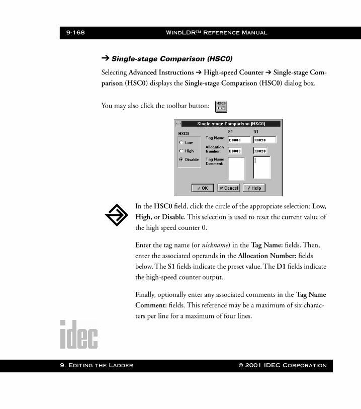
9-168 WindLDR™ Reference Manual
9. Editing t
WLDR ReferenceBook Page 168 Thursday, April 5, 2001 3:36 PM
➔ Single-stage Comparison (HSC0)
Selecting Advanced Instructions ➔ High-speed Counter ➔ Single-stage Com-
parison (HSC0) displays the Single-stage Comparison (HSC0) dialog box.
You may also click the toolbar button:
In the HSC0 field, click the circle of the appropriate selection: Low,
High, or Disable. This selection is used to reset the current value of
the high speed counter 0.
Enter the tag name (or nickname) in the Tag Name: fields. Then,
enter the associated operands in the Allocation Number: fields
below. The S1 fields indicate the preset value. The D1 fields indicate
the high-speed counter output.
Finally, optionally enter any associated comments in the Tag Name
Comment: fields. This reference may be a maximum of six charac-
ters per line for a maximum of four lines.
he Ladder © 2001 IDEC Corporation

WindLDR™ Reference Manual 9-169
WLDR ReferenceBook Page 169 Thursday, April 5, 2001 3:36 PM
Once the dialog box is complete, click the OK button to activate the
high-speed instruction on your ladder. To back out of this instruc-
tion without utilizing the high-speed instruction, click the Cancel
button.
To access on-line help, click the Help button.
High-speed counter 0 counts input pulses to input I0. When the current value is
equal to or greater than the preset value designated by source operand S1, the
output or internal relay designated by destination operand D1 is turned on.
The current value of the high-speed counter is reset to zero when the Micro3 or
Micro3C is powered up. The high-speed counter holds the current value while
the Micro3 or Micro3C is stopped and restarts counting input pulses starting
with the existing current value. Include the hard reset or soft reset in the user
program, if necessary.
NOTE: Only one HSC0–HSC3 and A/D instruction can be used in each user program.
S1 D1*********
HSC0LOW
© 2001 IDEC Corporation 9. Editing the Ladder
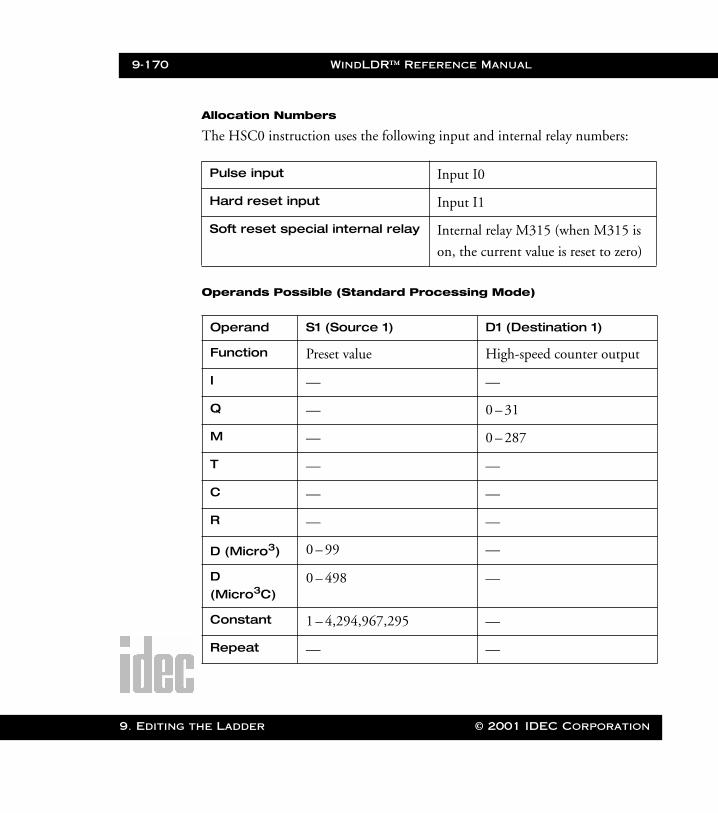
9-170 WindLDR™ Reference Manual
9. Editing t
WLDR ReferenceBook Page 170 Thursday, April 5, 2001 3:36 PM
Allocation Numbers
The HSC0 instruction uses the following input and internal relay numbers:
Operands Possible (Standard Processing Mode)
Pulse input Input I0
Hard reset input Input I1
Soft reset special internal relay Internal relay M315 (when M315 is
on, the current value is reset to zero)
Operand S1 (Source 1) D1 (Destination 1)
Function Preset value High-speed counter output
I — —
Q — 0 – 31
M — 0 – 287
T — —
C — —
R — —
D (Micro3) 0 – 99 —
D (Micro3C)
0 – 498 —
Constant 1 – 4,294,967,295 —
Repeat — —
he Ladder © 2001 IDEC Corporation
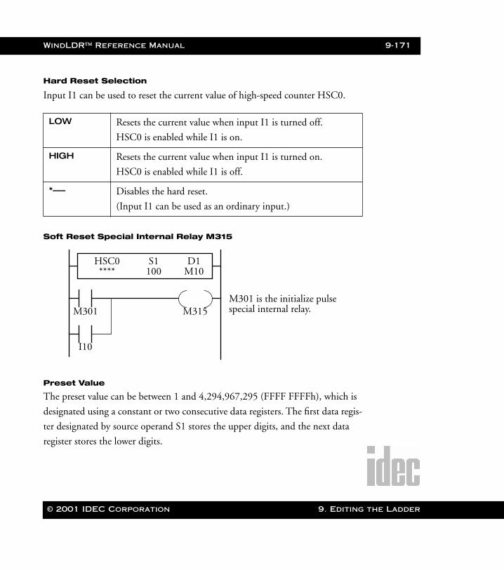
WindLDR™ Reference Manual 9-171
WLDR ReferenceBook Page 171 Thursday, April 5, 2001 3:36 PM
Hard Reset Selection
Input I1 can be used to reset the current value of high-speed counter HSC0.
Soft Reset Special Internal Relay M315
Preset Value
The preset value can be between 1 and 4,294,967,295 (FFFF FFFFh), which is
designated using a constant or two consecutive data registers. The first data regis-
ter designated by source operand S1 stores the upper digits, and the next data
register stores the lower digits.
LOW Resets the current value when input I1 is turned off.
HSC0 is enabled while I1 is on.
HIGH Resets the current value when input I1 is turned on.
HSC0 is enabled while I1 is off.
*––– Disables the hard reset.
(Input I1 can be used as an ordinary input.)
M301
I10
M315
S1 D1M10100
HSC0****
M301 is the initialize pulsespecial internal relay.
© 2001 IDEC Corporation 9. Editing the Ladder
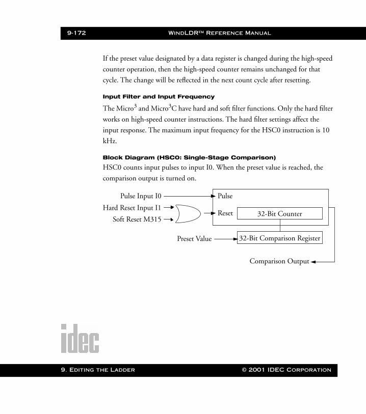
9-172 WindLDR™ Reference Manual
9. Editing t
WLDR ReferenceBook Page 172 Thursday, April 5, 2001 3:36 PM
If the preset value designated by a data register is changed during the high-speed
counter operation, then the high-speed counter remains unchanged for that
cycle. The change will be reflected in the next count cycle after resetting.
Input Filter and Input Frequency
The Micro3 and Micro3C have hard and soft filter functions. Only the hard filter
works on high-speed counter instructions. The hard filter settings affect the
input response. The maximum input frequency for the HSC0 instruction is 10
kHz.
Block Diagram (HSC0: Single-Stage Comparison)
HSC0 counts input pulses to input I0. When the preset value is reached, the
comparison output is turned on.
Pulse Input I0
Hard Reset Input I1
Soft Reset M315
Pulse
Reset
Preset Value
32-Bit Counter
32-Bit Comparison Register
Comparison Output
he Ladder © 2001 IDEC Corporation
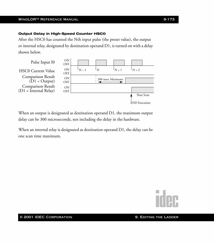
WindLDR™ Reference Manual 9-173
WLDR ReferenceBook Page 173 Thursday, April 5, 2001 3:36 PM
Output Delay in High-Speed Counter HSC0
After the HSC0 has counted the Nth input pulse (the preset value), the output
or internal relay, designated by destination operand D1, is turned on with a delay
shown below.
When an output is designated as destination operand D1, the maximum output
delay can be 300 microseconds, not including the delay in the hardware.
When an internal relay is designated as destination operand D1, the delay can be
one scan time maximum.
ONOFFPulse Input I0
HSC0 Current ValueComparison Result
(D1 = Output)Comparison Result
(D1 = Internal Relay)
ONOFF
ONOFF
ONOFF
N – 1 N N + 1 N + 2
300 msec Maximum
Next Scan
END Execution
© 2001 IDEC Corporation 9. Editing the Ladder
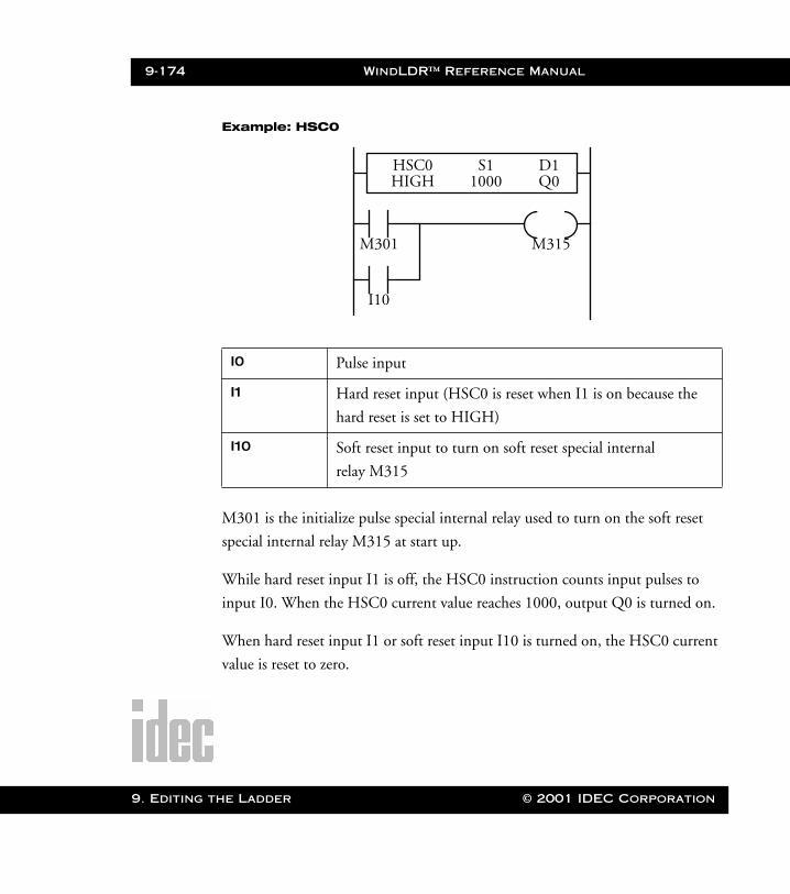
9-174 WindLDR™ Reference Manual
9. Editing t
WLDR ReferenceBook Page 174 Thursday, April 5, 2001 3:36 PM
Example: HSC0
M301 is the initialize pulse special internal relay used to turn on the soft reset
special internal relay M315 at start up.
While hard reset input I1 is off, the HSC0 instruction counts input pulses to
input I0. When the HSC0 current value reaches 1000, output Q0 is turned on.
When hard reset input I1 or soft reset input I10 is turned on, the HSC0 current
value is reset to zero.
I0 Pulse input
I1 Hard reset input (HSC0 is reset when I1 is on because the
hard reset is set to HIGH)
I10 Soft reset input to turn on soft reset special internal
relay M315
M301
I10
M315
S1 D1Q01000
HSC0HIGH
he Ladder © 2001 IDEC Corporation
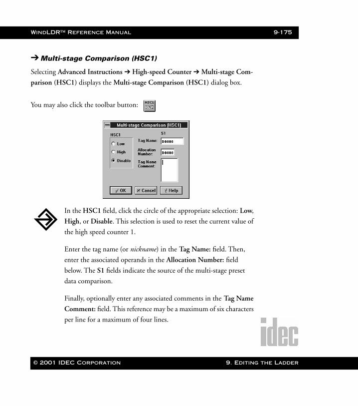
WindLDR™ Reference Manual 9-175
WLDR ReferenceBook Page 175 Thursday, April 5, 2001 3:36 PM
➔ Multi-stage Comparison (HSC1)
Selecting Advanced Instructions ➔ High-speed Counter ➔ Multi-stage Com-
parison (HSC1) displays the Multi-stage Comparison (HSC1) dialog box.
You may also click the toolbar button:
In the HSC1 field, click the circle of the appropriate selection: Low,
High, or Disable. This selection is used to reset the current value of
the high speed counter 1.
Enter the tag name (or nickname) in the Tag Name: field. Then,
enter the associated operands in the Allocation Number: field
below. The S1 fields indicate the source of the multi-stage preset
data comparison.
Finally, optionally enter any associated comments in the Tag Name
Comment: field. This reference may be a maximum of six characters
per line for a maximum of four lines.
© 2001 IDEC Corporation 9. Editing the Ladder
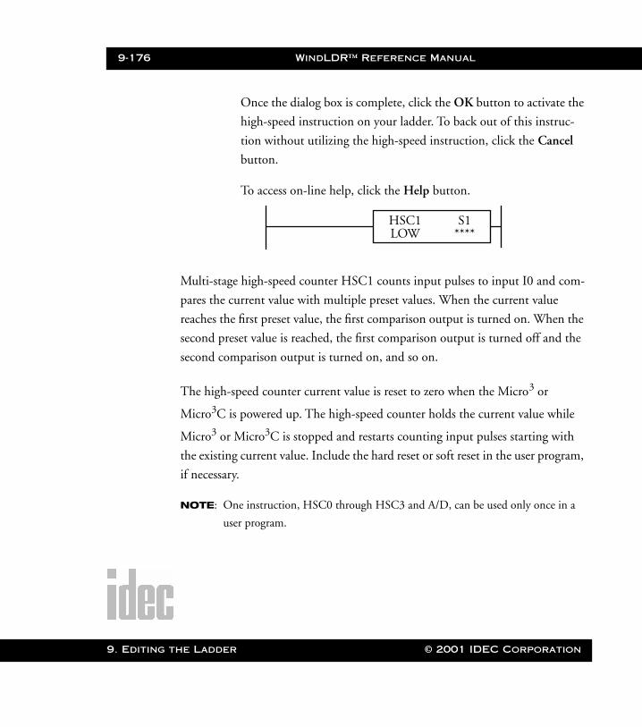
9-176 WindLDR™ Reference Manual
9. Editing t
WLDR ReferenceBook Page 176 Thursday, April 5, 2001 3:36 PM
Once the dialog box is complete, click the OK button to activate the
high-speed instruction on your ladder. To back out of this instruc-
tion without utilizing the high-speed instruction, click the Cancel
button.
To access on-line help, click the Help button.
Multi-stage high-speed counter HSC1 counts input pulses to input I0 and com-
pares the current value with multiple preset values. When the current value
reaches the first preset value, the first comparison output is turned on. When the
second preset value is reached, the first comparison output is turned off and the
second comparison output is turned on, and so on.
The high-speed counter current value is reset to zero when the Micro3 or
Micro3C is powered up. The high-speed counter holds the current value while
Micro3 or Micro3C is stopped and restarts counting input pulses starting with
the existing current value. Include the hard reset or soft reset in the user program,
if necessary.
NOTE: One instruction, HSC0 through HSC3 and A/D, can be used only once in a
user program.
S1****
HSC1LOW
he Ladder © 2001 IDEC Corporation
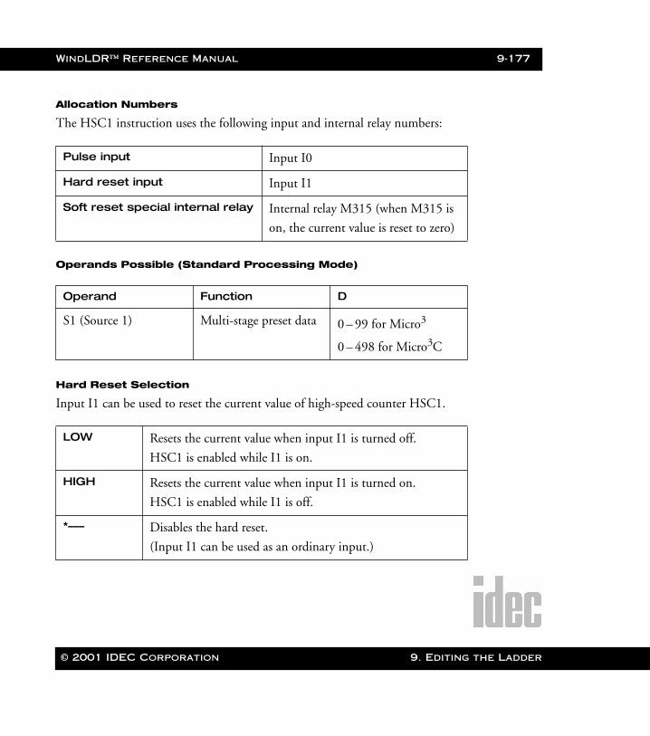
WindLDR™ Reference Manual 9-177
WLDR ReferenceBook Page 177 Thursday, April 5, 2001 3:36 PM
Allocation Numbers
The HSC1 instruction uses the following input and internal relay numbers:
Operands Possible (Standard Processing Mode)
Hard Reset Selection
Input I1 can be used to reset the current value of high-speed counter HSC1.
Pulse input Input I0
Hard reset input Input I1
Soft reset special internal relay Internal relay M315 (when M315 is
on, the current value is reset to zero)
Operand Function D
S1 (Source 1) Multi-stage preset data 0 – 99 for Micro3
0 – 498 for Micro3C
LOW Resets the current value when input I1 is turned off.
HSC1 is enabled while I1 is on.
HIGH Resets the current value when input I1 is turned on.
HSC1 is enabled while I1 is off.
*––– Disables the hard reset.
(Input I1 can be used as an ordinary input.)
© 2001 IDEC Corporation 9. Editing the Ladder

9-178 WindLDR™ Reference Manual
9. Editing t
WLDR ReferenceBook Page 178 Thursday, April 5, 2001 3:36 PM
Soft Reset Special Internal Relay M315
In addition to the hard reset using input I1, the current value of the high-speed
counter can be reset by turning special internal relay M315 on using another
input, output, or internal relay. M315, if used, must be programmed immedi-
ately after the HSC instruction as shown in the previous example.
M301
I10
M315
S1100
HSC1****
M301 is the initialize pulsespecial internal relay.
34464
D10
D11
D12
N
1
3392
200
3
D13
D14
D15
D16 201
10176
9
206
When data register D10 is designated as source operand S1
D10 + 3N – 2
D10 + 3N – 1
D10 + 3N
Quantity of preset stages
1st-stage preset (upper digits)
1st-stage preset (lower digits)
1st-stage output (200 = output Q0)
2nd-stage preset (upper digits)
2nd-stage preset (lower digits)
2nd-stage output (201 = output Q1)
100,000
200,000
600,000Nth-stage preset (upper digits)
Nth-stage preset (lower digits)
Nth-stage output (206 = output Q6)
he Ladder © 2001 IDEC Corporation
WindLDR™ Reference Manual 9-179
WLDR ReferenceBook Page 179 Thursday, April 5, 2001 3:36 PM
Multi-Stage Data Setting
The data of comparison stages, preset values, and comparison outputs are stored
in consecutive data registers starting with the data register designated by source
operand S1.
Preset Value
The preset value can be between 1 and 4,294,967,295 (FFFF FFFFh) which is
stored in two consecutive data registers. The first data register stores the upper
digits, and the next data register stores the lower digits.
If the preset value is changed during the high-speed counter operation, the high-
speed counter remains unchanged for that cycle. The change will be reflected in
the next count cycle after resetting.
Store the quantity of preset stages in the first data register.
In the next two data registers, store the upper and lower digits of the
preset value for the first stage.
In the fourth data register, store the destination of the first stage
comparison output, using the numeric allocation number of the
output or internal relay.
Store the data in these data registers before executing the HSC1
instruction.
© 2001 IDEC Corporation 9. Editing the Ladder
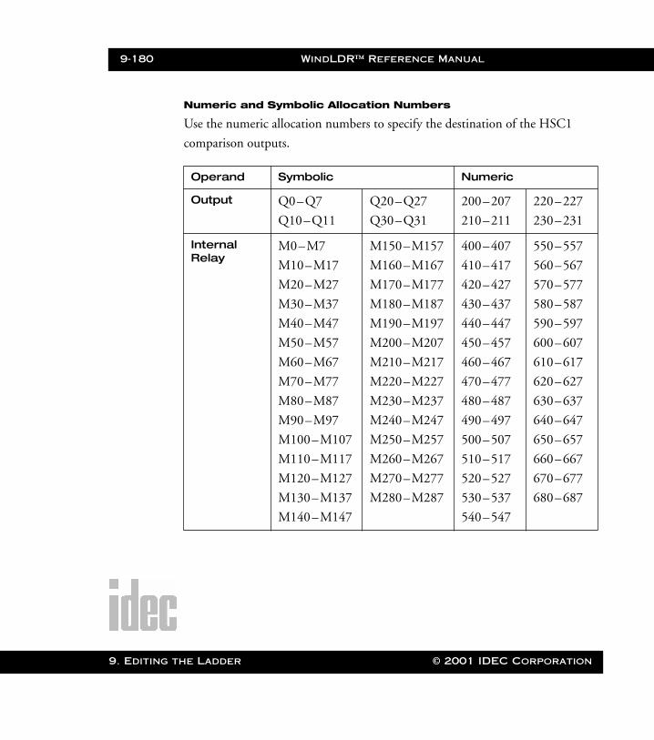
9-180 WindLDR™ Reference Manual
9. Editing t
WLDR ReferenceBook Page 180 Thursday, April 5, 2001 3:36 PM
Numeric and Symbolic Allocation Numbers
Use the numeric allocation numbers to specify the destination of the HSC1
comparison outputs.
Operand Symbolic Numeric
Output Q0–Q7
Q10–Q11
Q20–Q27
Q30–Q31
200–207
210–211
220–227
230–231
Internal Relay
M0–M7
M10–M17
M20–M27
M30–M37
M40–M47
M50–M57
M60–M67
M70–M77
M80–M87
M90–M97
M100–M107
M110–M117
M120–M127
M130–M137
M140–M147
M150–M157
M160–M167
M170–M177
M180–M187
M190–M197
M200–M207
M210–M217
M220–M227
M230–M237
M240–M247
M250–M257
M260–M267
M270–M277
M280–M287
400–407
410–417
420–427
430–437
440–447
450–457
460–467
470–477
480–487
490–497
500–507
510–517
520–527
530–537
540–547
550–557
560–567
570–577
580–587
590–597
600–607
610–617
620–627
630–637
640–647
650–657
660–667
670–677
680–687
he Ladder © 2001 IDEC Corporation
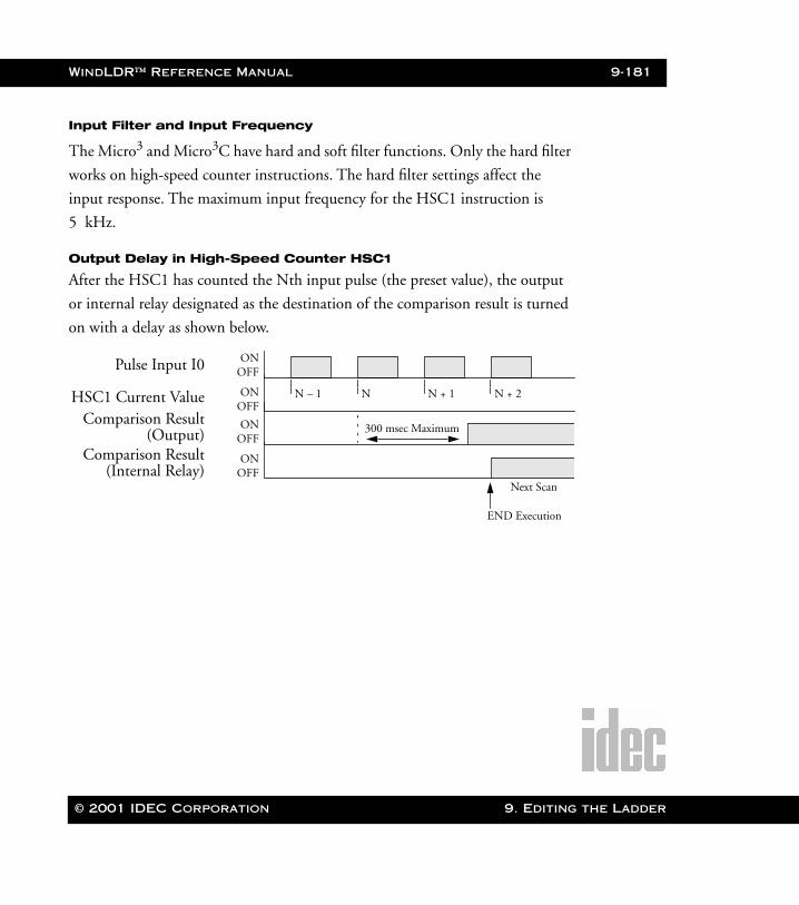
WindLDR™ Reference Manual 9-181
WLDR ReferenceBook Page 181 Thursday, April 5, 2001 3:36 PM
Input Filter and Input Frequency
The Micro3 and Micro3C have hard and soft filter functions. Only the hard filter
works on high-speed counter instructions. The hard filter settings affect the
input response. The maximum input frequency for the HSC1 instruction is
5 kHz.
Output Delay in High-Speed Counter HSC1
After the HSC1 has counted the Nth input pulse (the preset value), the output
or internal relay designated as the destination of the comparison result is turned
on with a delay as shown below.
ONOFFPulse Input I0
HSC1 Current ValueComparison Result
(Output)Comparison Result
(Internal Relay)
ONOFF
ONOFF
ONOFF
N – 1 N N + 1 N + 2
300 msec Maximum
Next Scan
END Execution
© 2001 IDEC Corporation 9. Editing the Ladder
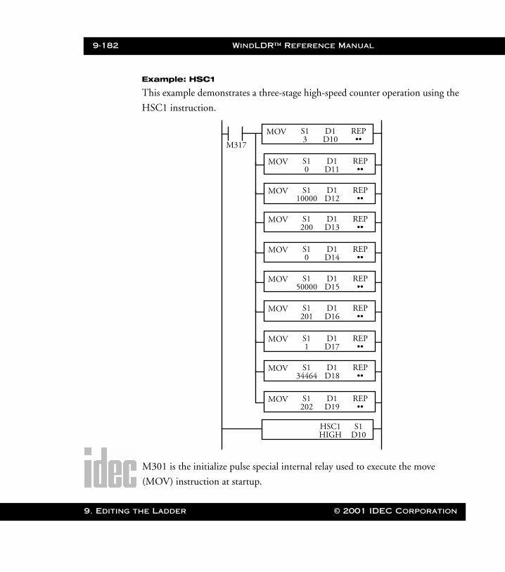
9-182 WindLDR™ Reference Manual
9. Editing t
WLDR ReferenceBook Page 182 Thursday, April 5, 2001 3:36 PM
Example: HSC1
This example demonstrates a three-stage high-speed counter operation using the
HSC1 instruction.
M301 is the initialize pulse special internal relay used to execute the move
(MOV) instruction at startup.
M317
S1 REP••
D1D10
MOV3
S1 REP••
D1D11
MOV0
S1 REP••
D1D12
MOV10000
S1 REP••
D1D13
MOV200
S1 REP••
D1D14
MOV0
S1 REP••
D1D15
MOV50000
S1 REP••
D1D16
MOV201
S1 REP••
D1D17
MOV1
S1 REP••
D1D18
MOV34464
S1 REP••
D1D19
MOV202
S1D10
HSC1HIGH
he Ladder © 2001 IDEC Corporation
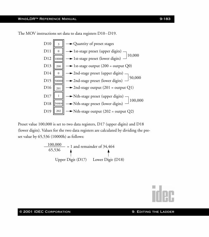
WindLDR™ Reference Manual 9-183
WLDR ReferenceBook Page 183 Thursday, April 5, 2001 3:36 PM
The MOV instructions set data to data registers D10–D19.
Preset value 100,000 is set to two data registers, D17 (upper digits) and D18
(lower digits). Values for the two data registers are calculated by dividing the pre-
set value by 65,536 (10000h) as follows:
10000
D10
D11
D12
3
0
50000
200
0
D13
D14
D15
D16 201
34464
1
202
D17
D18
D19
Quantity of preset stages
1st-stage preset (upper digits)
1st-stage preset (lower digits)
1st-stage output (200 = output Q0)
2nd-stage preset (upper digits)
2nd-stage preset (lower digits)
2nd-stage output (201 = output Q1)
10,000
50,000
100,000Nth-stage preset (upper digits)
Nth-stage preset (lower digits)
Nth-stage output (202 = output Q2)
100,00065,536
= 1 and remainder of 34,464
Upper Digit (D17) Lower Digit (D18)
© 2001 IDEC Corporation 9. Editing the Ladder
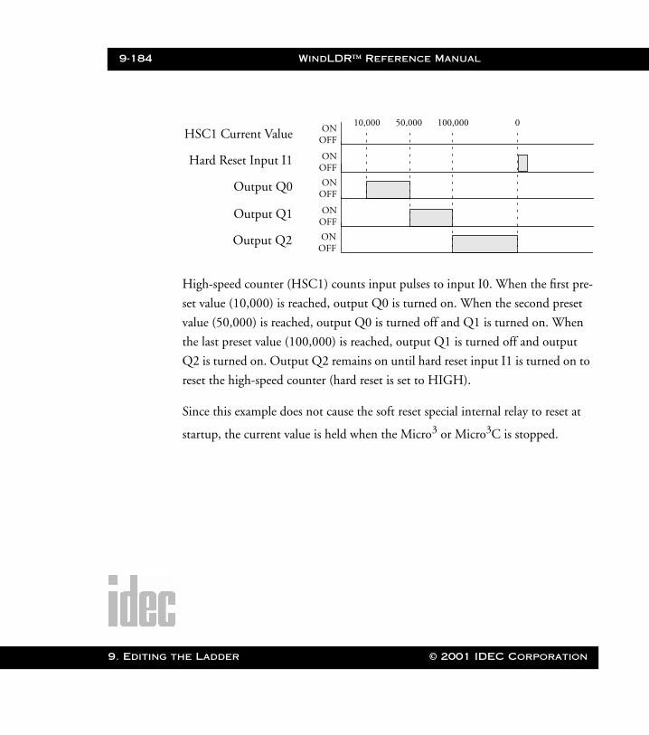
9-184 WindLDR™ Reference Manual
9. Editing t
WLDR ReferenceBook Page 184 Thursday, April 5, 2001 3:36 PM
High-speed counter (HSC1) counts input pulses to input I0. When the first pre-
set value (10,000) is reached, output Q0 is turned on. When the second preset
value (50,000) is reached, output Q0 is turned off and Q1 is turned on. When
the last preset value (100,000) is reached, output Q1 is turned off and output
Q2 is turned on. Output Q2 remains on until hard reset input I1 is turned on to
reset the high-speed counter (hard reset is set to HIGH).
Since this example does not cause the soft reset special internal relay to reset at
startup, the current value is held when the Micro3 or Micro3C is stopped.
ONOFFHSC1 Current Value
Hard Reset Input I1
Output Q0
Output Q1
ONOFF
ONOFF
ONOFF
10,000 50,000 100,000 0
Output Q2 ONOFF
he Ladder © 2001 IDEC Corporation
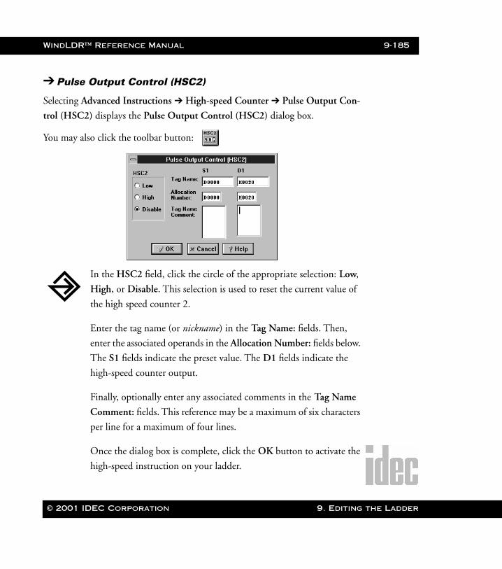
WindLDR™ Reference Manual 9-185
WLDR ReferenceBook Page 185 Thursday, April 5, 2001 3:36 PM
➔ Pulse Output Control (HSC2)
Selecting Advanced Instructions ➔ High-speed Counter ➔ Pulse Output Con-
trol (HSC2) displays the Pulse Output Control (HSC2) dialog box.
You may also click the toolbar button:
In the HSC2 field, click the circle of the appropriate selection: Low,
High, or Disable. This selection is used to reset the current value of
the high speed counter 2.
Enter the tag name (or nickname) in the Tag Name: fields. Then,
enter the associated operands in the Allocation Number: fields below.
The S1 fields indicate the preset value. The D1 fields indicate the
high-speed counter output.
Finally, optionally enter any associated comments in the Tag Name
Comment: fields. This reference may be a maximum of six characters
per line for a maximum of four lines.
Once the dialog box is complete, click the OK button to activate the
high-speed instruction on your ladder.
© 2001 IDEC Corporation 9. Editing the Ladder
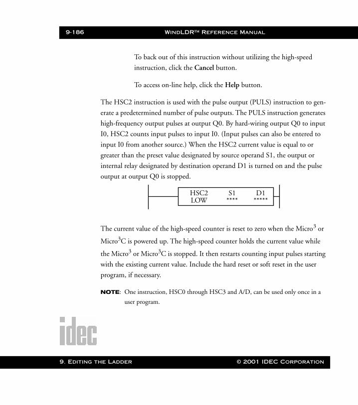
9-186 WindLDR™ Reference Manual
9. Editing t
WLDR ReferenceBook Page 186 Thursday, April 5, 2001 3:36 PM
To back out of this instruction without utilizing the high-speed
instruction, click the Cancel button.
To access on-line help, click the Help button.
The HSC2 instruction is used with the pulse output (PULS) instruction to gen-
erate a predetermined number of pulse outputs. The PULS instruction generates
high-frequency output pulses at output Q0. By hard-wiring output Q0 to input
I0, HSC2 counts input pulses to input I0. (Input pulses can also be entered to
input I0 from another source.) When the HSC2 current value is equal to or
greater than the preset value designated by source operand S1, the output or
internal relay designated by destination operand D1 is turned on and the pulse
output at output Q0 is stopped.
The current value of the high-speed counter is reset to zero when the Micro3 or
Micro3C is powered up. The high-speed counter holds the current value while
the Micro3 or Micro3C is stopped. It then restarts counting input pulses starting
with the existing current value. Include the hard reset or soft reset in the user
program, if necessary.
NOTE: One instruction, HSC0 through HSC3 and A/D, can be used only once in a
user program.
S1 D1*********
HSC2LOW
he Ladder © 2001 IDEC Corporation
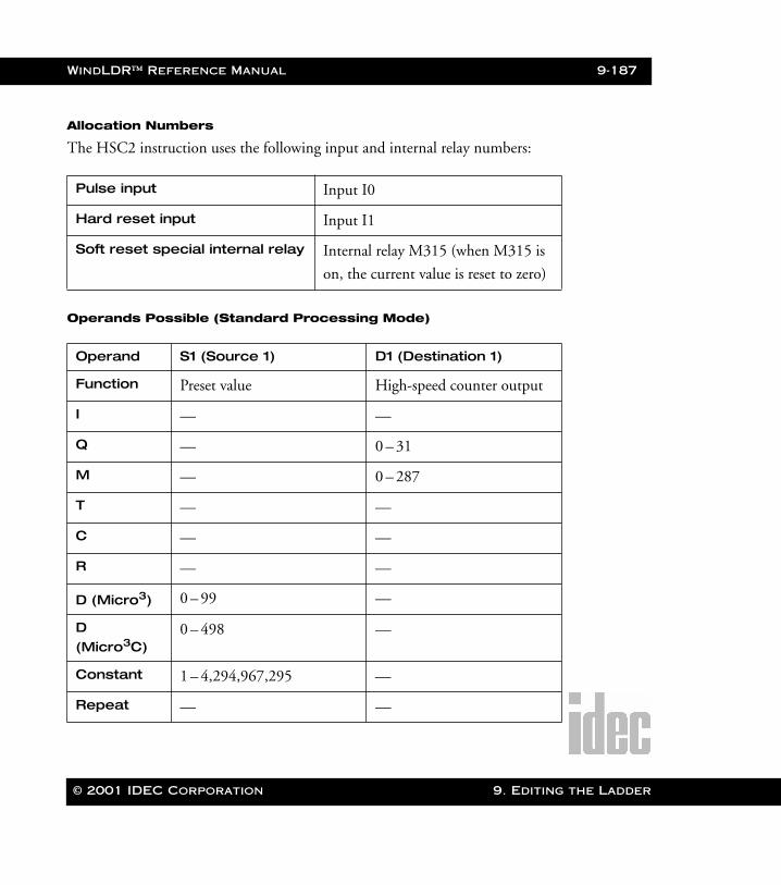
WindLDR™ Reference Manual 9-187
WLDR ReferenceBook Page 187 Thursday, April 5, 2001 3:36 PM
Allocation Numbers
The HSC2 instruction uses the following input and internal relay numbers:
Operands Possible (Standard Processing Mode)
Pulse input Input I0
Hard reset input Input I1
Soft reset special internal relay Internal relay M315 (when M315 is
on, the current value is reset to zero)
Operand S1 (Source 1) D1 (Destination 1)
Function Preset value High-speed counter output
I — —
Q — 0 – 31
M — 0 – 287
T — —
C — —
R — —
D (Micro3) 0 – 99 —
D (Micro3C)
0 – 498 —
Constant 1 – 4,294,967,295 —
Repeat — —
© 2001 IDEC Corporation 9. Editing the Ladder
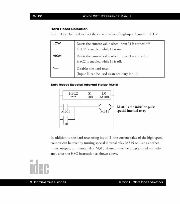
9-188 WindLDR™ Reference Manual
9. Editing t
WLDR ReferenceBook Page 188 Thursday, April 5, 2001 3:36 PM
Hard Reset Selection
Input I1 can be used to reset the current value of high-speed counter HSC2.
Soft Reset Special Internal Relay M315
In addition to the hard reset using input I1, the current value of the high-speed
counter can be reset by turning special internal relay M315 on using another
input, output, or internal relay. M315, if used, must be programmed immedi-
ately after the HSC instruction as shown above.
LOW Resets the current value when input I1 is turned off.
HSC2 is enabled while I1 is on.
HIGH Resets the current value when input I1 is turned on.
HSC2 is enabled while I1 is off.
*––– Disables the hard reset.
(Input I1 can be used as an ordinary input.)
M301
I10
M315
S1 D1M100100
HSC2****
M301 is the initialize pulsespecial internal relay.
he Ladder © 2001 IDEC Corporation
WindLDR™ Reference Manual 9-189
WLDR ReferenceBook Page 189 Thursday, April 5, 2001 3:36 PM
Preset Value
The preset value can be between 1 and 4,294,967,295 (FFFF FFFFh) which is
designated using a constant or two consecutive data registers. The first data regis-
ter designated by source operand S1 stores the upper digits, and the next data
register stores the lower digits.
If the preset value designated by a data register is changed during the high-speed
counter operation, then the high-speed counter remains unchanged for that
cycle. The change will be reflected in the next count cycle after resetting.
Input Filter
The Micro3 and Micro3C have hard and soft filter functions. Only the hard filter
works on high-speed counter instructions. The hard filter settings affect the
input response. The maximum input frequency for the HSC2 instruction is
5 kHz (4 kHz when using the program loader).
© 2001 IDEC Corporation 9. Editing the Ladder
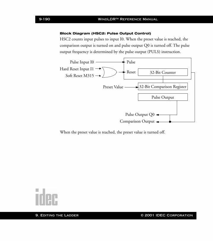
9-190 WindLDR™ Reference Manual
9. Editing t
WLDR ReferenceBook Page 190 Thursday, April 5, 2001 3:36 PM
Block Diagram (HSC2: Pulse Output Control)
HSC2 counts input pulses to input I0. When the preset value is reached, the
comparison output is turned on and pulse output Q0 is turned off. The pulse
output frequency is determined by the pulse output (PULS) instruction.
When the preset value is reached, the preset value is turned off.
Comparison Output
Pulse Input I0
Hard Reset Input I1
Soft Reset M315
Pulse
Reset
Preset Value
32-Bit Counter
32-Bit Comparison Register
Pulse Output
Pulse Output Q0
he Ladder © 2001 IDEC Corporation

WindLDR™ Reference Manual 9-191
WLDR ReferenceBook Page 191 Thursday, April 5, 2001 3:36 PM
Output Delay in High-Speed Counter HSC2
After the HSC2 has counted the Nth input pulse (the preset value), the output
or internal relay, designated by destination operand D1, is turned on with a delay
as shown below.
➔ Gate Control (HSC3)
Selecting Advanced Instructions ➔ High-speed Counter ➔ Gate Control
(HSC3) displays the Gate Control (HSC3) dialog box.
You may also click the toolbar button:
ONOFFPulse Input I0
HSC2 Current Value
Output Pulse
Comparison Result
ONOFF
ONOFF
ONOFF
N-1
Output Q0 ONOFF
Stop Signal
(D1 = Output)
N
190 msec maximum
300 msec maximum
© 2001 IDEC Corporation 9. Editing the Ladder
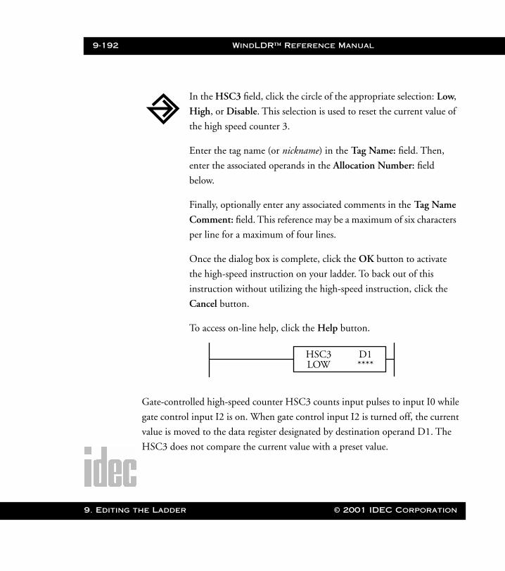
9-192 WindLDR™ Reference Manual
9. Editing t
WLDR ReferenceBook Page 192 Thursday, April 5, 2001 3:36 PM
Gate-controlled high-speed counter HSC3 counts input pulses to input I0 while
gate control input I2 is on. When gate control input I2 is turned off, the current
value is moved to the data register designated by destination operand D1. The
HSC3 does not compare the current value with a preset value.
In the HSC3 field, click the circle of the appropriate selection: Low,
High, or Disable. This selection is used to reset the current value of
the high speed counter 3.
Enter the tag name (or nickname) in the Tag Name: field. Then,
enter the associated operands in the Allocation Number: field
below.
Finally, optionally enter any associated comments in the Tag Name
Comment: field. This reference may be a maximum of six characters
per line for a maximum of four lines.
Once the dialog box is complete, click the OK button to activate
the high-speed instruction on your ladder. To back out of this
instruction without utilizing the high-speed instruction, click the
Cancel button.
To access on-line help, click the Help button.
D1****
HSC3LOW
he Ladder © 2001 IDEC Corporation
WindLDR™ Reference Manual 9-193
WLDR ReferenceBook Page 193 Thursday, April 5, 2001 3:36 PM
The HSC3 can count up to 65535. When another input pulse enters at 65535,
the current value becomes 0 and special internal relay M316 (HSC3 overflow) is
turned on.
The current value of the high-speed counter is reset to zero when the Micro3 or
Micro3C is powered up. The high-speed counter holds the current value while
the Micro3 or Micro3C is stopped and restarts counting input pulses starting
with the existing current value. Include the hard reset or soft reset in the user
program, if necessary.
NOTE: One instruction, HSC0 through HSC3 and A/D, can be used only once in a
user program.
Allocation Numbers
The HSC3 instruction uses the following input and internal relay numbers:
Pulse input Input I0
Hard reset input Input I1
Gate input Input I2
Soft reset special internal relay Internal relay M315 (when M315 is
on, the current value is reset to zero)
HSC3 overflow special internal relay
Internal relay M316
© 2001 IDEC Corporation 9. Editing the Ladder
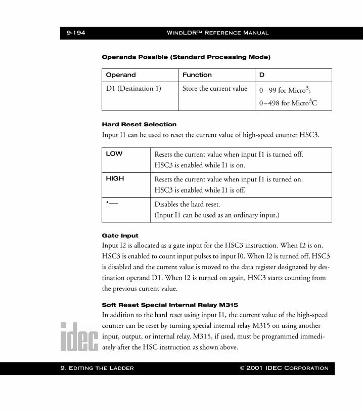
9-194 WindLDR™ Reference Manual
9. Editing t
WLDR ReferenceBook Page 194 Thursday, April 5, 2001 3:36 PM
Operands Possible (Standard Processing Mode)
Hard Reset Selection
Input I1 can be used to reset the current value of high-speed counter HSC3.
Gate Input
Input I2 is allocated as a gate input for the HSC3 instruction. When I2 is on,
HSC3 is enabled to count input pulses to input I0. When I2 is turned off, HSC3
is disabled and the current value is moved to the data register designated by des-
tination operand D1. When I2 is turned on again, HSC3 starts counting from
the previous current value.
Soft Reset Special Internal Relay M315
In addition to the hard reset using input I1, the current value of the high-speed
counter can be reset by turning special internal relay M315 on using another
input, output, or internal relay. M315, if used, must be programmed immedi-
ately after the HSC instruction as shown above.
Operand Function D
D1 (Destination 1) Store the current value 0 – 99 for Micro3;
0–498 for Micro3C
LOW Resets the current value when input I1 is turned off.
HSC3 is enabled while I1 is on.
HIGH Resets the current value when input I1 is turned on.
HSC3 is enabled while I1 is off.
*––– Disables the hard reset.
(Input I1 can be used as an ordinary input.)
he Ladder © 2001 IDEC Corporation
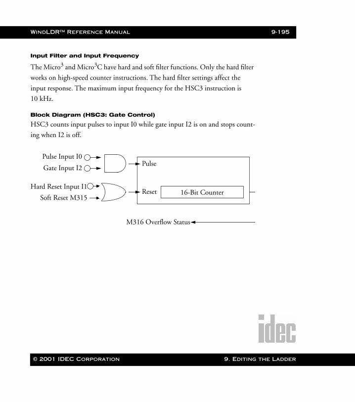
WindLDR™ Reference Manual 9-195
WLDR ReferenceBook Page 195 Thursday, April 5, 2001 3:36 PM
Input Filter and Input Frequency
The Micro3 and Micro3C have hard and soft filter functions. Only the hard filter
works on high-speed counter instructions. The hard filter settings affect the
input response. The maximum input frequency for the HSC3 instruction is
10 kHz.
Block Diagram (HSC3: Gate Control)
HSC3 counts input pulses to input I0 while gate input I2 is on and stops count-
ing when I2 is off.
Pulse Input I0
Hard Reset Input I1
Soft Reset M315
Pulse
Reset 16-Bit Counter
M316 Overflow Status
Gate Input I2
© 2001 IDEC Corporation 9. Editing the Ladder
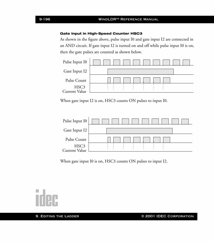
9-196 WindLDR™ Reference Manual
9. Editing t
WLDR ReferenceBook Page 196 Thursday, April 5, 2001 3:36 PM
Gate Input in High-Speed Counter HSC3
As shown in the figure above, pulse input I0 and gate input I2 are connected in
an AND circuit. If gate input I2 is turned on and off while pulse input I0 is on,
then the gate pulses are counted as shown below.
When gate input I2 is on, HSC3 counts ON pulses to input I0.
When gate input I0 is on, HSC3 counts ON pulses to input I2.
Pulse Input I0
Gate Input I2
Pulse Count
HSC3 Current Value
Pulse Input I0
Gate Input I2
Pulse Count
HSC3 Current Value
he Ladder © 2001 IDEC Corporation
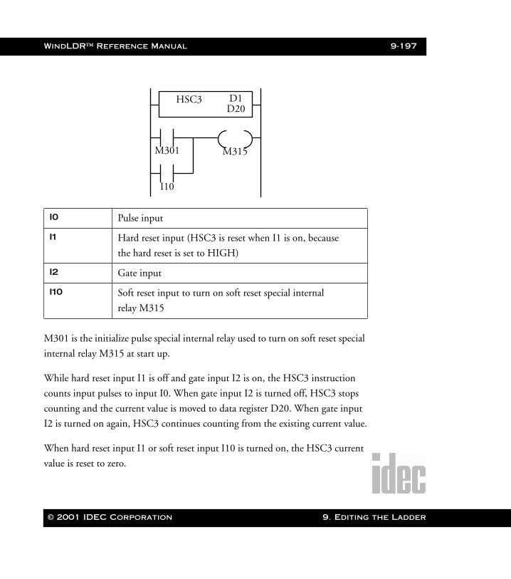
WindLDR™ Reference Manual 9-197
WLDR ReferenceBook Page 197 Thursday, April 5, 2001 3:36 PM
M301 is the initialize pulse special internal relay used to turn on soft reset special
internal relay M315 at start up.
While hard reset input I1 is off and gate input I2 is on, the HSC3 instruction
counts input pulses to input I0. When gate input I2 is turned off, HSC3 stops
counting and the current value is moved to data register D20. When gate input
I2 is turned on again, HSC3 continues counting from the existing current value.
When hard reset input I1 or soft reset input I10 is turned on, the HSC3 current
value is reset to zero.
I0 Pulse input
I1 Hard reset input (HSC3 is reset when I1 is on, because
the hard reset is set to HIGH)
I2 Gate input
I10 Soft reset input to turn on soft reset special internal
relay M315
M301
I10
M315
D1D20
HSC3
© 2001 IDEC Corporation 9. Editing the Ladder
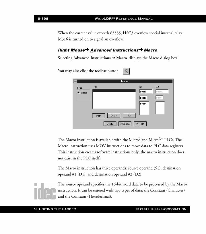
9-198 WindLDR™ Reference Manual
9. Editing t
WLDR ReferenceBook Page 198 Thursday, April 5, 2001 3:36 PM
When the current value exceeds 65535, HSC3 overflow special internal relay
M316 is turned on to signal an overflow.
Right Mouse➔ Advanced Instructions➔ Macro
Selecting Advanced Instructions ➔ Macro displays the Macro dialog box.
You may also click the toolbar button:
The Macro instruction is available with the Micro3 and Micro3C PLCs. The
Macro instruction uses MOV instructions to move data to PLC data registers.
This instruction creates software instructions only; the macro instruction does
not exist in the PLC itself.
The Macro instruction has three operands: source operand (S1), destination
operand #1 (D1), and destination operand #2 (D2).
The source operand specifies the 16-bit word data to be processed by the Macro
instruction. It can be entered with two types of data: the Constant (Character)
and the Constant (Hexadecimal).
he Ladder © 2001 IDEC Corporation
WindLDR™ Reference Manual 9-199
WLDR ReferenceBook Page 199 Thursday, April 5, 2001 3:36 PM
The constant (character) can be any character on the keyboard (ASCII charac-
ter). The constant (hex decimal) can be any hex code. The constant (hex deci-
mal) also includes all ENQ characters of the American National Standard
Institute (ANSI), i.e. 0X00 to 0XFF.
The destination operand specifies the 16-bit word data to store the result of the
Macro instruction. The destination operand #1 (D1) serves as the beginning of
the data register, while destination operand #2 (D2) serves as the ending of the
data register. When D1 is set, the Macro instruction looks at the length of S1 to
set D2. The user does not set D2; it is set by the Macro instruction.
Type:
The Macro instruction remains selected in the Type: field.
S1
When set up, descriptions of the source operands display in the S1 field.
Clicking on any of these instructions displays the corresponding macro
information.
To set up a new macro, click the Insert button. Refer to page 9-201 for
more information.
Complete the fields as displayed below in the field descriptions.
Once the dialog box is complete, click the OK button to activate the
macro instruction on your ladder. To back out of this instruction
without utilizing the Macro instruction, click the Cancel button.
To access on-line help, click the Help button.
© 2001 IDEC Corporation 9. Editing the Ladder

9-200 WindLDR™ Reference Manual
9. Editing t
WLDR ReferenceBook Page 200 Thursday, April 5, 2001 3:36 PM
D1
Originally, when no instructions are entered, only one white field dis-
plays below the D1 field. Destination operand #1 (D1) serves as the
beginning of the data register. When D1 is set, the Macro instruction
looks at the length of S1 to set D2.
Once information is entered in the D1 field or once an instruction is
selected from the S1 field, two more white fields display below the D1
instruction. The middle field displays the allocation number of D1.
Enter a tag name in the lower field.
D2
Originally, when no instructions are entered, only one white field dis-
plays below the D2 field. Destination operand #2 (D2) serves as the
ending of the data register. Once information is entered in the D1 field
or once an instruction is selected from the S1 field, then the correspond-
ing information displays in the D2 field.
he Ladder © 2001 IDEC Corporation
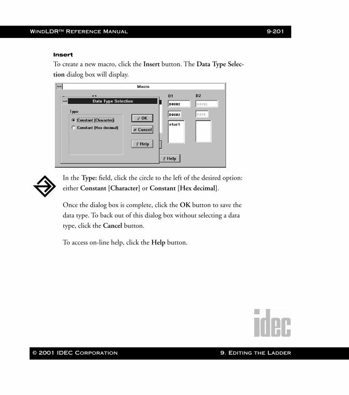
WindLDR™ Reference Manual 9-201
WLDR ReferenceBook Page 201 Thursday, April 5, 2001 3:36 PM
Insert
To create a new macro, click the Insert button. The Data Type Selec-
tion dialog box will display.
In the Type: field, click the circle to the left of the desired option:
either Constant [Character] or Constant [Hex decimal].
Once the dialog box is complete, click the OK button to save the
data type. To back out of this dialog box without selecting a data
type, click the Cancel button.
To access on-line help, click the Help button.
© 2001 IDEC Corporation 9. Editing the Ladder
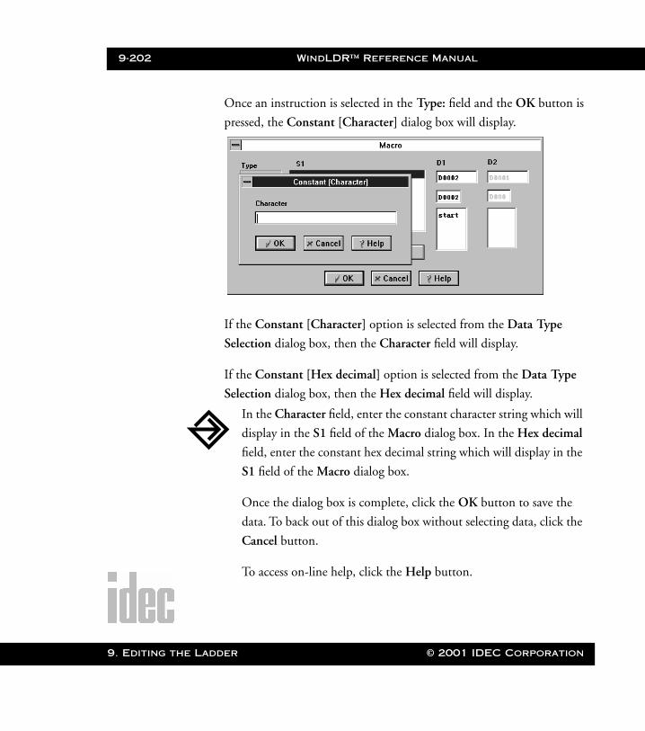
9-202 WindLDR™ Reference Manual
9. Editing t
WLDR ReferenceBook Page 202 Thursday, April 5, 2001 3:36 PM
Once an instruction is selected in the Type: field and the OK button is
pressed, the Constant [Character] dialog box will display.
If the Constant [Character] option is selected from the Data Type
Selection dialog box, then the Character field will display.
If the Constant [Hex decimal] option is selected from the Data Type
Selection dialog box, then the Hex decimal field will display.
In the Character field, enter the constant character string which will
display in the S1 field of the Macro dialog box. In the Hex decimal
field, enter the constant hex decimal string which will display in the
S1 field of the Macro dialog box.
Once the dialog box is complete, click the OK button to save the
data. To back out of this dialog box without selecting data, click the
Cancel button.
To access on-line help, click the Help button.
he Ladder © 2001 IDEC Corporation
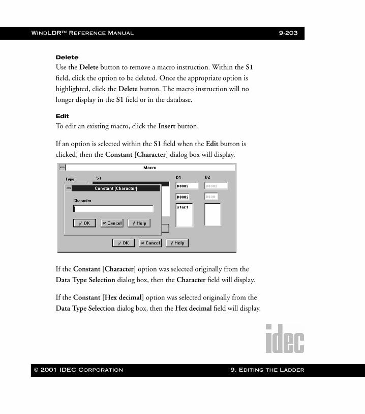
WindLDR™ Reference Manual 9-203
WLDR ReferenceBook Page 203 Thursday, April 5, 2001 3:36 PM
Delete
Use the Delete button to remove a macro instruction. Within the S1
field, click the option to be deleted. Once the appropriate option is
highlighted, click the Delete button. The macro instruction will no
longer display in the S1 field or in the database.
Edit
To edit an existing macro, click the Insert button.
If an option is selected within the S1 field when the Edit button is
clicked, then the Constant [Character] dialog box will display.
If the Constant [Character] option was selected originally from the
Data Type Selection dialog box, then the Character field will display.
If the Constant [Hex decimal] option was selected originally from the
Data Type Selection dialog box, then the Hex decimal field will display.
© 2001 IDEC Corporation 9. Editing the Ladder
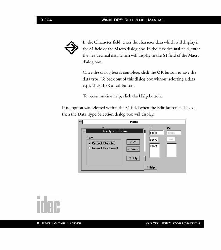
9-204 WindLDR™ Reference Manual
9. Editing t
WLDR ReferenceBook Page 204 Thursday, April 5, 2001 3:36 PM
If no option was selected within the S1 field when the Edit button is clicked,
then the Data Type Selection dialog box will display.
In the Character field, enter the character data which will display in
the S1 field of the Macro dialog box. In the Hex decimal field, enter
the hex decimal data which will display in the S1 field of the Macro
dialog box.
Once the dialog box is complete, click the OK button to save the
data type. To back out of this dialog box without selecting a data
type, click the Cancel button.
To access on-line help, click the Help button.
he Ladder © 2001 IDEC Corporation
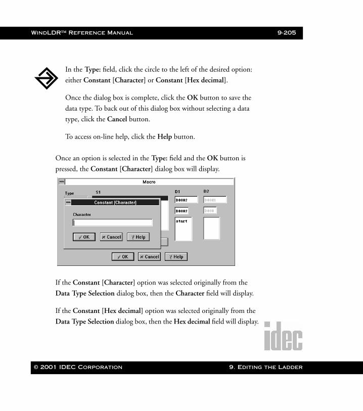
WindLDR™ Reference Manual 9-205
WLDR ReferenceBook Page 205 Thursday, April 5, 2001 3:36 PM
Once an option is selected in the Type: field and the OK button is
pressed, the Constant [Character] dialog box will display.
If the Constant [Character] option was selected originally from the
Data Type Selection dialog box, then the Character field will display.
If the Constant [Hex decimal] option was selected originally from the
Data Type Selection dialog box, then the Hex decimal field will display.
In the Type: field, click the circle to the left of the desired option:
either Constant [Character] or Constant [Hex decimal].
Once the dialog box is complete, click the OK button to save the
data type. To back out of this dialog box without selecting a data
type, click the Cancel button.
To access on-line help, click the Help button.
© 2001 IDEC Corporation 9. Editing the Ladder
9-206 WindLDR™ Reference Manual
9. Editing t
WLDR ReferenceBook Page 206 Thursday, April 5, 2001 3:36 PM
Right Mouse➔ Advanced Instructions➔ No Operation (NOP)
Selecting Advanced Instructions ➔ No Operation (NOP) ➔ literally programs a
rung to have no operation. No operands can be programmed for the NOP
instruction.
The NOP instruction may serve as a place-holder. Another use would be to add a
delay to the Micro3 or Micro3C scan time, in order to simulate communication
with a machine or application, for debugging purposes.
Right Mouse➔ Insert
Selecting Insert ➔ adds a ladder line, column, or rung before the current rung in
your ladder program.
Click on the position before which you wish to insert the ladder instruction. A
gray box will highlight this area.
In the Character field, enter the character data which will display in
the S1 field of the Macro dialog box. In the Hex decimal field, enter
the hex decimal data which will display in the S1 field of the Macro
dialog box.
Once the dialog box is complete, click the OK button to save the
data. To back out of this dialog box without selecting data, click the
Cancel button.
To access on-line help, click the Help button.
he Ladder © 2001 IDEC Corporation
WindLDR™ Reference Manual 9-207
WLDR ReferenceBook Page 207 Thursday, April 5, 2001 3:36 PM
Then, select Insert ➔ Ladder Line to add a ladder line before the area which is
highlighted by the gray box. Select Insert ➔ Column to add a column before the
area which is highlighted by the gray box. Select Insert ➔ Rung to add a rung
before the area which is highlighted by the gray box.
Right Mouse➔ Append
Selecting Advanced Instructions ➔ Append ➔ adds an attached ladder line, col-
umn, or rung after the current rung in your ladder program.
Click on the position after which you wish to append the ladder instruction. A
gray box will highlight this area.
Then, select Append ➔ Ladder Line to add a ladder line after the area which is
highlighted by the gray box. Select Append ➔ Column to add a column after the
area which is highlighted by the gray box. Select Append ➔ Rung to add a rung
after the area which is highlighted by the gray box.
Right Mouse➔ Delete
Selecting Delete ➔ removes a ladder line, column, or rung from your ladder pro-
gram.
Click on the position which you wish to delete the ladder instruction. A gray box
will highlight this area.
Then, select Delete ➔ Ladder Line to remove the ladder line which is high-
lighted by the gray box. Select Delete ➔ Column to remove the column which is
highlighted by the gray box. Select Delete ➔ Rung to remove the rung which is
highlighted by the gray box.
© 2001 IDEC Corporation 9. Editing the Ladder
9-208 WindLDR™ Reference Manual
9. Editing t
WLDR ReferenceBook Page 208 Thursday, April 5, 2001 3:36 PM
Right Mouse➔ Split Rung
Selecting Split Rung separates two rungs of your ladder program.
Within your ladder program, click on the lower of the two ladder rungs which
you wish to separate. A gray box will highlight this area. Then select Split Rung
to separates these two rungs.
Right Mouse➔ Join Rung
Selecting Join Rung connects two rung of your ladder program.
Within your ladder program, click on the upper of the two ladder rungs which
you wish to join. A gray box will highlight this area. Then select Join Rung to
connect these two rungs.
Right Mouse➔ Disable Rung
Selecting Disable Rung makes the functionality of the rung latent. The instruc-
tions will remain visible on the rung; however, its function will be disabled.
Within your ladder program, click on the rung of the ladder which you wish to
disable. A gray box will highlight this area. Then select Disable Rung.
Disabled rungs appear gray on the ladder diagram.
he Ladder © 2001 IDEC Corporation
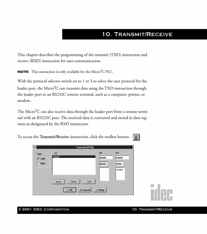
© 2001 IDEC Corporation
WLDR ReferenceBook Page 1 Thursday, April 5, 2001 3:36 PM
10. Transmit/Receive
This chapter describes the programming of the transmit (TXD) instruction and
receive (RXD) instruction for user communication.
NOTE: This instruction is only available for the Micro3C PLC.
With the protocol selector switch set to 1 or 3 to select the user protocol for the
loader port, the Micro3C can transmit data using the TXD instruction through
the loader port to an RS232C remote terminal, such as a computer, printer, or
modem.
The Micro3C can also receive data through the loader port from a remote termi-
nal with an RS232C port. The received data is converted and stored in data reg-
isters as designated by the RXD instruction.
To access the Transmit/Receive instruction, click the toolbar button:
10. Transmit/Receive

10-2 WindLDR™ Reference Manual
10. Trans
WLDR ReferenceBook Page 2 Thursday, April 5, 2001 3:36 PM
Type
Click the circle to the left of the desired option: either TXD for the
transmit instruction or RXD for the receive instruction.
S1
Originally, when no options are entered, only the blank tag name field
displays below the S1 field. When set up, descriptions of the source
operands display in the S1 field. Clicking on any of these options dis-
plays the corresponding transmit or receive information. Transmit data
designated by operand S1 can be a maximum of 200 bytes.
To add a new source operand, click the Insert button. Refer to
page 10-4 for complete instructions.
D1
Originally, when no options are entered, only the blank tag name field
displays below the D1 field. When transmission is complete, an output
or internal relay designated by operand D1 is turned on.
Complete the fields as explained below in the field descriptions.
Once the dialog box is complete, click the OK button to insert the
transmit or receive instruction on your ladder. To back out of this
dialog box without utilizing the transmit or receive instruction,
click the Cancel button.
To access on-line help, click the Help button.
mit/Receive © 2001 IDEC Corporation
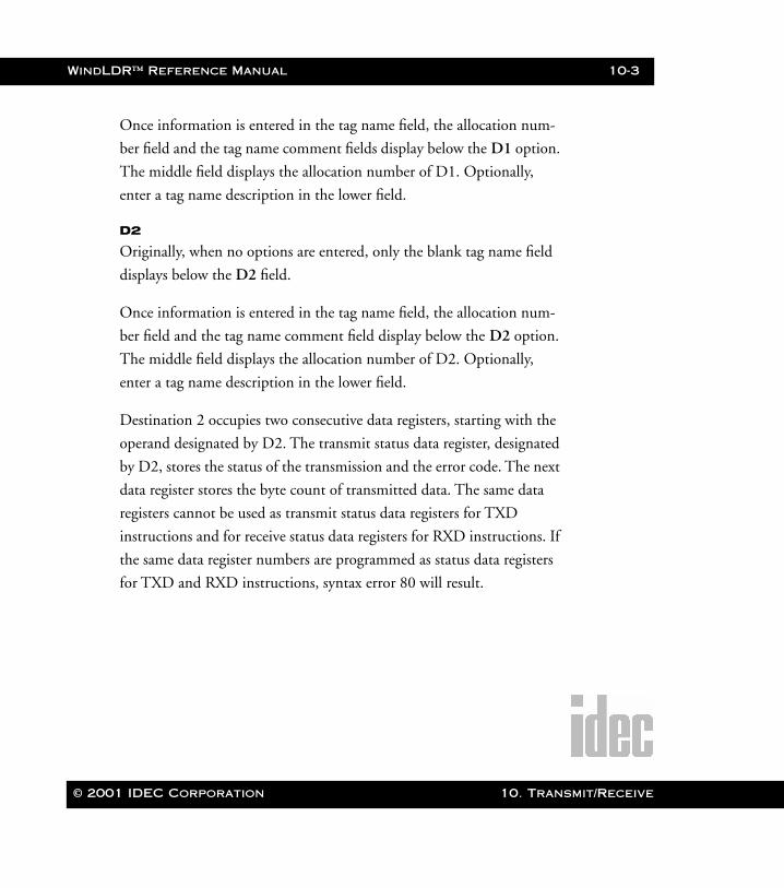
WindLDR™ Reference Manual 10-3
WLDR ReferenceBook Page 3 Thursday, April 5, 2001 3:36 PM
Once information is entered in the tag name field, the allocation num-
ber field and the tag name comment fields display below the D1 option.
The middle field displays the allocation number of D1. Optionally,
enter a tag name description in the lower field.
D2
Originally, when no options are entered, only the blank tag name field
displays below the D2 field.
Once information is entered in the tag name field, the allocation num-
ber field and the tag name comment field display below the D2 option.
The middle field displays the allocation number of D2. Optionally,
enter a tag name description in the lower field.
Destination 2 occupies two consecutive data registers, starting with the
operand designated by D2. The transmit status data register, designated
by D2, stores the status of the transmission and the error code. The next
data register stores the byte count of transmitted data. The same data
registers cannot be used as transmit status data registers for TXD
instructions and for receive status data registers for RXD instructions. If
the same data register numbers are programmed as status data registers
for TXD and RXD instructions, syntax error 80 will result.
© 2001 IDEC Corporation 10. Transmit/Receive
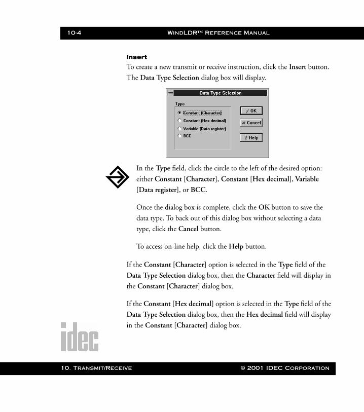
10-4 WindLDR™ Reference Manual
10. Transm
WLDR ReferenceBook Page 4 Thursday, April 5, 2001 3:36 PM
Insert
To create a new transmit or receive instruction, click the Insert button.
The Data Type Selection dialog box will display.
If the Constant [Character] option is selected in the Type field of the
Data Type Selection dialog box, then the Character field will display in
the Constant [Character] dialog box.
If the Constant [Hex decimal] option is selected in the Type field of the
Data Type Selection dialog box, then the Hex decimal field will display
in the Constant [Character] dialog box.
In the Type field, click the circle to the left of the desired option:
either Constant [Character], Constant [Hex decimal], Variable
[Data register], or BCC.
Once the dialog box is complete, click the OK button to save the
data type. To back out of this dialog box without selecting a data
type, click the Cancel button.
To access on-line help, click the Help button.
it/Receive © 2001 IDEC Corporation
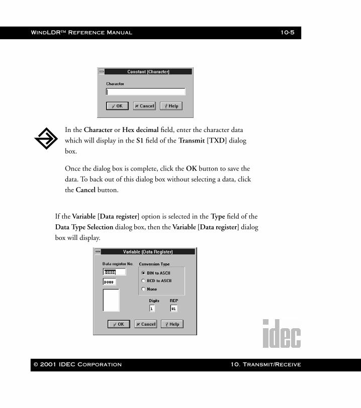
WindLDR™ Reference Manual 10-5
WLDR ReferenceBook Page 5 Thursday, April 5, 2001 3:36 PM
If the Variable [Data register] option is selected in the Type field of the
Data Type Selection dialog box, then the Variable [Data register] dialog
box will display.
In the Character or Hex decimal field, enter the character data
which will display in the S1 field of the Transmit [TXD] dialog
box.
Once the dialog box is complete, click the OK button to save the
data. To back out of this dialog box without selecting a data, click
the Cancel button.
© 2001 IDEC Corporation 10. Transmit/Receive
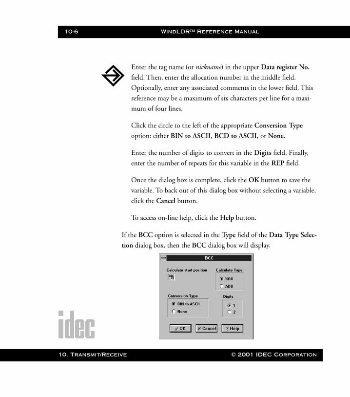
10-6 WindLDR™ Reference Manual
10. Transm
WLDR ReferenceBook Page 6 Thursday, April 5, 2001 3:36 PM
If the BCC option is selected in the Type field of the Data Type Selec-
tion dialog box, then the BCC dialog box will display.
Enter the tag name (or nickname) in the upper Data register No.
field. Then, enter the allocation number in the middle field.
Optionally, enter any associated comments in the lower field. This
reference may be a maximum of six characters per line for a maxi-
mum of four lines.
Click the circle to the left of the appropriate Conversion Type
option: either BIN to ASCII, BCD to ASCII, or None.
Enter the number of digits to convert in the Digits field. Finally,
enter the number of repeats for this variable in the REP field.
Once the dialog box is complete, click the OK button to save the
variable. To back out of this dialog box without selecting a variable,
click the Cancel button.
To access on-line help, click the Help button.
it/Receive © 2001 IDEC Corporation
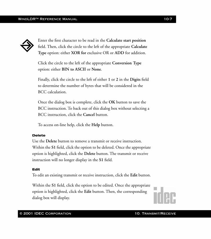
WindLDR™ Reference Manual 10-7
WLDR ReferenceBook Page 7 Thursday, April 5, 2001 3:36 PM
Delete
Use the Delete button to remove a transmit or receive instruction.
Within the S1 field, click the option to be deleted. Once the appropriate
option is highlighted, click the Delete button. The transmit or receive
instruction will no longer display in the S1 field.
Edit
To edit an existing transmit or receive instruction, click the Edit button.
Within the S1 field, click the option to be edited. Once the appropriate
option is highlighted, click the Edit button. Then, the corresponding
dialog box will display.
Enter the first character to be read in the Calculate start position
field. Then, click the circle to the left of the appropriate Calculate
Type option: either XOR for exclusive OR or ADD for addition.
Click the circle to the left of the appropriate Conversion Type
option: either BIN to ASCII or None.
Finally, click the circle to the left of either 1 or 2 in the Digits field
to determine the number of bytes that will be considered in the
BCC calculation.
Once the dialog box is complete, click the OK button to save the
BCC instruction. To back out of this dialog box without selecting a
BCC instruction, click the Cancel button.
To access on-line help, click the Help button.
© 2001 IDEC Corporation 10. Transmit/Receive
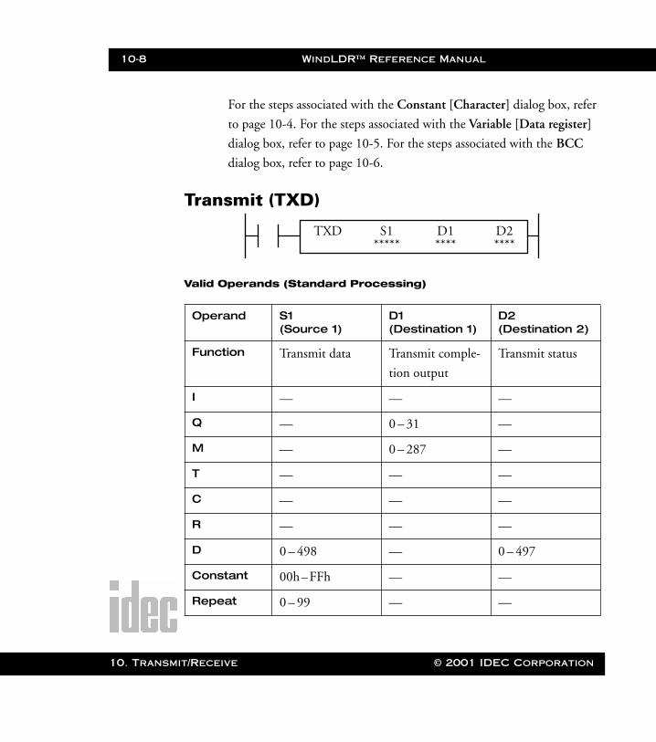
10-8 WindLDR™ Reference Manual
10. Transm
WLDR ReferenceBook Page 8 Thursday, April 5, 2001 3:36 PM
For the steps associated with the Constant [Character] dialog box, refer
to page 10-4. For the steps associated with the Variable [Data register]
dialog box, refer to page 10-5. For the steps associated with the BCC
dialog box, refer to page 10-6.
Transmit (TXD)
Valid Operands (Standard Processing)
Operand S1 (Source 1)
D1 (Destination 1)
D2 (Destination 2)
Function Transmit data Transmit comple-
tion output
Transmit status
I — — —
Q — 0 – 31 —
M — 0 – 287 —
T — — —
C — — —
R — — —
D 0 – 498 — 0 – 497
Constant 00h–FFh — —
Repeat 0 – 99 — —
TXD S1 D2***** ****
D1****
it/Receive © 2001 IDEC Corporation
WindLDR™ Reference Manual 10-9
WLDR ReferenceBook Page 9 Thursday, April 5, 2001 3:36 PM
Transmit data, designated by operand S1, can be a maximum of 200 bytes.
When transmission is complete, the output or internal relay, designated by oper-
and D1, is turned on.
Destination 2 occupies two consecutive data registers, starting with the operand
designated by D2. The transmit status data register, designated by D2, stores the
status of the transmission and the error code. The next data register stores the
byte count of transmitted data. The same data registers cannot be used as trans-
mit status data registers for TXD instructions and for receive status data registers
for RXD instructions. If the same data register numbers are programmed as sta-
tus data registers for TXD and RXD instructions, syntax error 80 will result.
Precautions for Programming TXD Instruction
• The Micro3C has five formatting areas for executing TXD instructions. Thus, more than five TXD instructions cannot be executed at the same time. An error code is set to the transmit status data register, designated by oper-and D2, in all excessive TXD instructions and cannot be executed.
• If the input for a TXD instruction is turned on while another TXD instruc-tion is executed, then the subsequent transmit instruction is executed two scan times after the preceding TXD instruction is completed.
• Since TXD instructions are executed in each scan while an input is on, a pulse input from an SOTU or SOTD instruction should be used as required.
• In the high-speed processing mode, user communication instructions TXD and RXD cannot be used.
© 2001 IDEC Corporation 10. Transmit/Receive
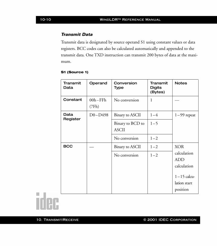
10-10 WindLDR™ Reference Manual
10. Transm
WLDR ReferenceBook Page 10 Thursday, April 5, 2001 3:36 PM
Transmit Data
Transmit data is designated by source operand S1 using constant values or data
registers. BCC codes can also be calculated automatically and appended to the
transmit data. One TXD instruction can transmit 200 bytes of data at the maxi-
mum.
S1 (Source 1)
Transmit Data
Operand Conversion Type
Transmit Digits (Bytes)
Notes
Constant 00h–FFh
(7Fh)
No conversion 1 —
Data Register
D0–D498 Binary to ASCII 1–4 1–99 repeat
Binary to BCD to
ASCII
1–5
No conversion 1–2
BCC — Binary to ASCII 1–2 XOR
calculation
ADD
calculation
1–15 calcu-
lation start
position
No conversion 1–2
it/Receive © 2001 IDEC Corporation
WindLDR™ Reference Manual 10-11
WLDR ReferenceBook Page 11 Thursday, April 5, 2001 3:36 PM
Designating Constant as S1
When a constant value is designated as source operand S1, one-byte data is trans-
mitted without conversion. The valid transmit data value depends on the data
bits selected in the FUN8 loader port communication mode setting. When eight
data bits are selected, 00h–FFh is transmitted. When seven data bits are selected
as the default, 00h–7Fh is transmitted. Constant values are entered in hexadeci-
mal notation into the source data.
Designating Data Register as S1
When a data register is designated as source operand S1, conversion types and
transmit digits must also be designated. The data stored in the designated data
register is converted, and a designated quantity of digits of the resulting data is
transmitted. Conversion types are available in binary to ASCII, binary to BCD
to ASCII, and no conversion.
When a repeat is designated, the data of as many data registers as repeat cycles are
transmitted, starting with the designated data register. Up to 99 repeat cycles can
be used.
© 2001 IDEC Corporation 10. Transmit/Receive
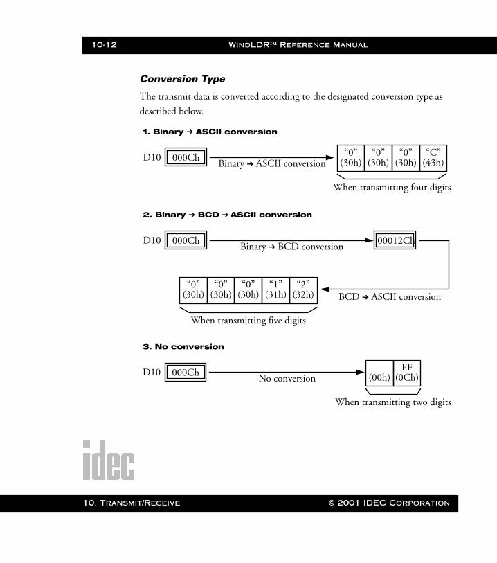
10-12 WindLDR™ Reference Manual
10. Transm
WLDR ReferenceBook Page 12 Thursday, April 5, 2001 3:36 PM
Conversion Type
The transmit data is converted according to the designated conversion type as
described below.
Binary ➔ ASCII conversion
1. Binary ➔ ASCII conversion
D10 000Ch “0”(30h)
When transmitting four digits
“0”(30h)
“0”(30h)
“C”(43h)
Binary ➔ BCD conversion
2. Binary ➔ BCD ➔ ASCII conversion
D10 000Ch
“0”(30h)
When transmitting five digits
“0”(30h)
“0”(30h)
“1”(31h)
00012Ch
BCD ➔ ASCII conversion“2”
(32h)
No conversion
3. No conversion
D10 000Ch (00h)
When transmitting two digits
FF(0Ch)
it/Receive © 2001 IDEC Corporation
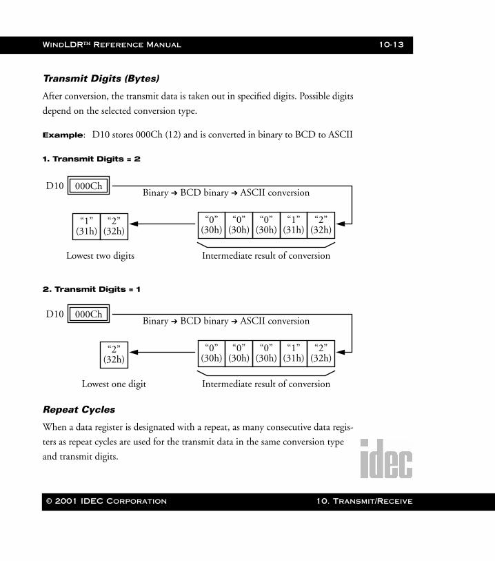
WindLDR™ Reference Manual 10-13
WLDR ReferenceBook Page 13 Thursday, April 5, 2001 3:36 PM
Transmit Digits (Bytes)
After conversion, the transmit data is taken out in specified digits. Possible digits
depend on the selected conversion type.
Example: D10 stores 000Ch (12) and is converted in binary to BCD to ASCII
1. Transmit Digits = 2
2. Transmit Digits = 1
Repeat Cycles
When a data register is designated with a repeat, as many consecutive data regis-
ters as repeat cycles are used for the transmit data in the same conversion type
and transmit digits.
Binary ➔ BCD binary ➔ ASCII conversionD10 000Ch
“0”(30h)
Intermediate result of conversion
“0”(30h)
“0”(30h)
“1”(31h)
“2”(32h)
“1”(31h)
Lowest two digits
“2”(32h)
Binary ➔ BCD binary ➔ ASCII conversionD10 000Ch
“0”(30h)
Intermediate result of conversion
“0”(30h)
“0”(30h)
“1”(31h)
“2”(32h)
Lowest one digit
“2”(32h)
© 2001 IDEC Corporation 10. Transmit/Receive
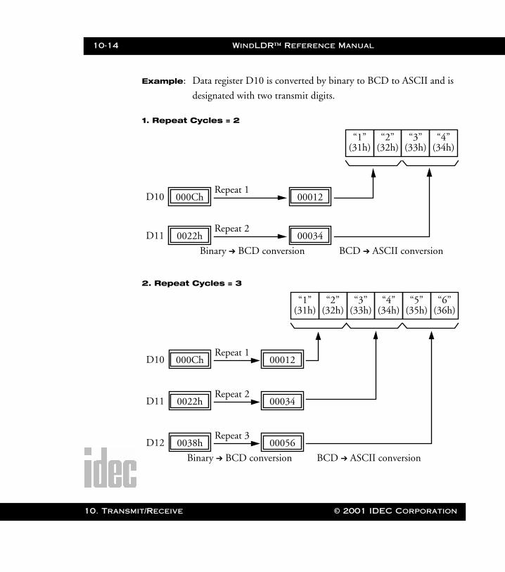
10-14 WindLDR™ Reference Manual
10. Transm
WLDR ReferenceBook Page 14 Thursday, April 5, 2001 3:36 PM
Example: Data register D10 is converted by binary to BCD to ASCII and is
designated with two transmit digits.
1. Repeat Cycles = 2
2. Repeat Cycles = 3
Binary ➔ BCD conversion
D10 000Ch
“1”(31h)
“2”(32h)
“3”(33h)
“4”(34h)
BCD ➔ ASCII conversion
Repeat 100012
D11 0022hRepeat 2
00034
Binary ➔ BCD conversion
D10 000Ch
“3”(33h)
“4”(34h)
“5”(35h)
“6”(36h)
BCD ➔ ASCII conversion
Repeat 100012
D11 0022hRepeat 2
00034
D12 0038hRepeat 3
00056
“1”(31h)
“2”(32h)
it/Receive © 2001 IDEC Corporation
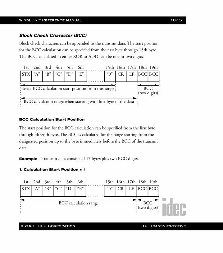
WindLDR™ Reference Manual 10-15
WLDR ReferenceBook Page 15 Thursday, April 5, 2001 3:36 PM
Block Check Character (BCC)
Block check characters can be appended to the transmit data. The start position
for the BCC calculation can be specified from the first byte through 15th byte.
The BCC, calculated in either XOR or ADD, can be one or two digits.
BCC Calculation Start Position
The start position for the BCC calculation can be specified from the first byte
through fifteenth byte. The BCC is calculated for the range starting from the
designated position up to the byte immediately before the BCC of the transmit
data.
Example: Transmit data consists of 17 bytes plus two BCC digits.
1. Calculation Start Position = 1
STX
1st
“A”
2nd
“B”
3rd
“C”
4th
“D”
5th
“E”
6th
“0”
15th
CR
16th
LF
17th
BCC
18th
BCC
19th
Select BCC calculation start position from this range
BCC calculation range when starting with first byte of the data
BCC(two digits)
STX
1st
“A”
2nd
“B”
3rd
“C”
4th
“D”
5th
“E”
6th
“0”
15th
CR
16th
LF
17th
BCC
18th
BCC
19th
BCC calculation range BCC(two digits)
© 2001 IDEC Corporation 10. Transmit/Receive
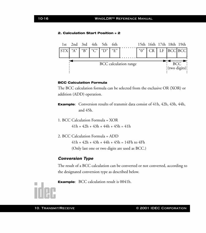
10-16 WindLDR™ Reference Manual
10. Transm
WLDR ReferenceBook Page 16 Thursday, April 5, 2001 3:36 PM
2. Calculation Start Position = 2
BCC Calculation Formula
The BCC calculation formula can be selected from the exclusive OR (XOR) or
addition (ADD) operation.
Example: Conversion results of transmit data consist of 41h, 42h, 43h, 44h,
and 45h.
1. BCC Calculation Formula = XOR
41h + 42h + 43h + 44h + 45h = 41h
2. BCC Calculation Formula = ADD
41h + 42h + 43h + 44h + 45h = 14Fh to 4Fh
(Only last one or two digits are used as BCC.)
Conversion Type
The result of a BCC calculation can be converted or not converted, according to
the designated conversion type as described below.
Example: BCC calculation result is 0041h.
STX
1st
“A”
2nd
“B”
3rd
“C”
4th
“D”
5th
“E”
6th
“0”
15th
CR
16th
LF
17th
BCC
18th
BCC
19th
BCC calculation range BCC(two digits)
it/Receive © 2001 IDEC Corporation
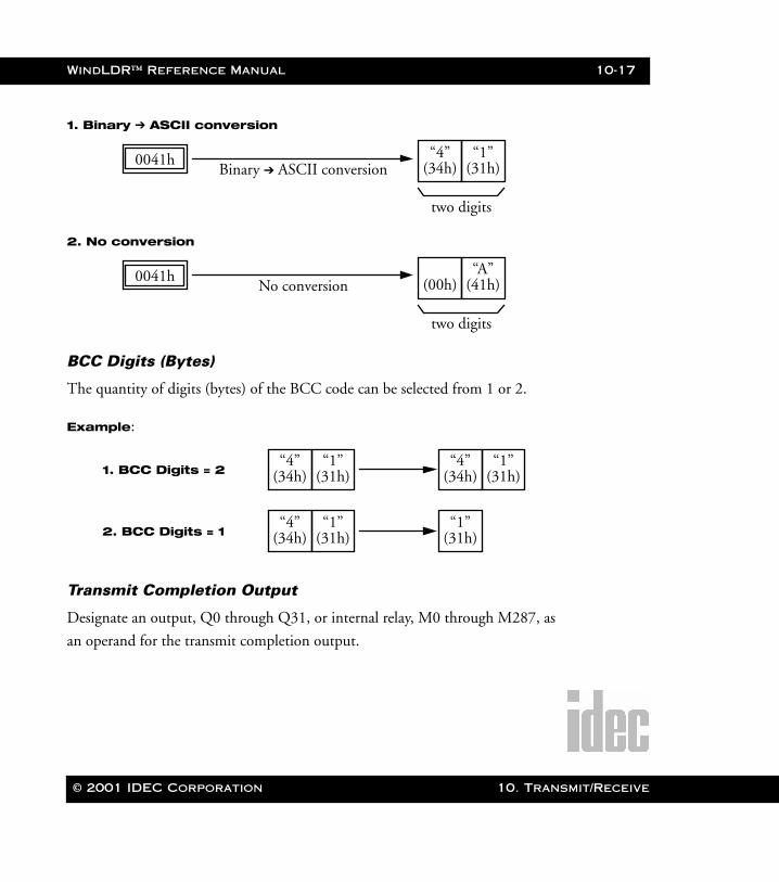
WindLDR™ Reference Manual 10-17
WLDR ReferenceBook Page 17 Thursday, April 5, 2001 3:36 PM
1. Binary ➔ ASCII conversion
2. No conversion
BCC Digits (Bytes)
The quantity of digits (bytes) of the BCC code can be selected from 1 or 2.
Example:
Transmit Completion Output
Designate an output, Q0 through Q31, or internal relay, M0 through M287, as
an operand for the transmit completion output.
Binary ➔ ASCII conversion0041h “4”
(34h)“1”
(31h)
two digits
No conversion0041h (00h)
“A”(41h)
two digits
“4”(34h)
“1”(31h)
“4”(34h)
“1”(31h)1. BCC Digits = 2
“4”(34h)
“1”(31h)
“1”(31h)2. BCC Digits = 1
© 2001 IDEC Corporation 10. Transmit/Receive
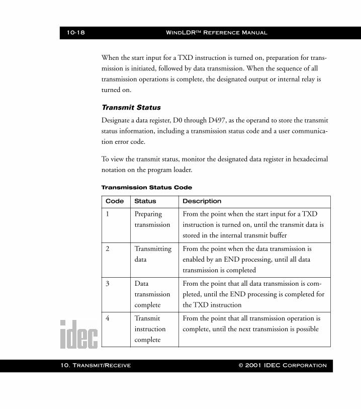
10-18 WindLDR™ Reference Manual
10. Transm
WLDR ReferenceBook Page 18 Thursday, April 5, 2001 3:36 PM
When the start input for a TXD instruction is turned on, preparation for trans-
mission is initiated, followed by data transmission. When the sequence of all
transmission operations is complete, the designated output or internal relay is
turned on.
Transmit Status
Designate a data register, D0 through D497, as the operand to store the transmit
status information, including a transmission status code and a user communica-
tion error code.
To view the transmit status, monitor the designated data register in hexadecimal
notation on the program loader.
Transmission Status Code
Code Status Description
1 Preparing
transmission
From the point when the start input for a TXD
instruction is turned on, until the transmit data is
stored in the internal transmit buffer
2 Transmitting
data
From the point when the data transmission is
enabled by an END processing, until all data
transmission is completed
3 Data
transmission
complete
From the point that all data transmission is com-
pleted, until the END processing is completed for
the TXD instruction
4 Transmit
instruction
complete
From the point that all transmission operation is
complete, until the next transmission is possible
it/Receive © 2001 IDEC Corporation
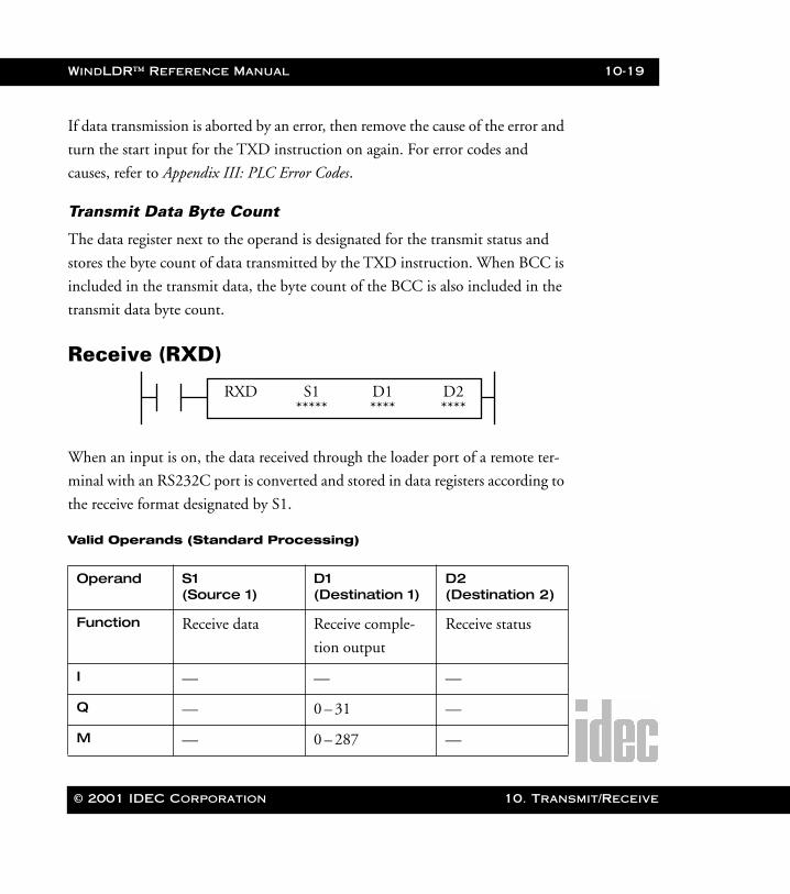
WindLDR™ Reference Manual 10-19
WLDR ReferenceBook Page 19 Thursday, April 5, 2001 3:36 PM
If data transmission is aborted by an error, then remove the cause of the error and
turn the start input for the TXD instruction on again. For error codes and
causes, refer to Appendix III: PLC Error Codes.
Transmit Data Byte Count
The data register next to the operand is designated for the transmit status and
stores the byte count of data transmitted by the TXD instruction. When BCC is
included in the transmit data, the byte count of the BCC is also included in the
transmit data byte count.
Receive (RXD)
When an input is on, the data received through the loader port of a remote ter-
minal with an RS232C port is converted and stored in data registers according to
the receive format designated by S1.
Valid Operands (Standard Processing)
Operand S1 (Source 1)
D1 (Destination 1)
D2 (Destination 2)
Function Receive data Receive comple-
tion output
Receive status
I — — —
Q — 0 – 31 —
M — 0 – 287 —
RXD S1 D2***** ****
D1****
© 2001 IDEC Corporation 10. Transmit/Receive

10-20 WindLDR™ Reference Manual
10. Transm
WLDR ReferenceBook Page 20 Thursday, April 5, 2001 3:36 PM
The receive format designated by operand S1 can be a maximum of 200 bytes.
When data is completely received, the output or internal relay, designated by
operand D1, is turned on.
Destination 2 occupies two consecutive data registers starting with the operand
designated by D2. The receive status data register, designated by D2, stores the
status of the data received and the error code. The next data register stores the
byte count of received data. The same data registers cannot be used as both trans-
mit status data registers for TXD instructions and receive status data registers for
RXD instructions. If the same data register numbers are programmed as status
data registers for TXD and RXD instructions, syntax error 80 will result.
Precautions for Programming RXD Instruction
• The Micro3C can execute a maximum of five RXD instructions that have a start delimiter at the same time. If a start delimiter is not programmed in
RXD instructions, then the Micro3C can execute only one receive instruc-tion at a time. If the start input for an RXD instruction is turned on while another RXD instruction without a start delimiter is executed, then a user communication error occurs.
T — — —
C — — —
R — — —
D 0 – 498 — 0 – 497
Constant 00h–FFh — —
Repeat 0 – 99 — —
it/Receive © 2001 IDEC Corporation
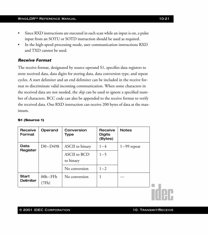
WindLDR™ Reference Manual 10-21
WLDR ReferenceBook Page 21 Thursday, April 5, 2001 3:36 PM
• Since RXD instructions are executed in each scan while an input is on, a pulse input from an SOTU or SOTD instruction should be used as required.
• In the high-speed processing mode, user communication instructions RXD and TXD cannot be used.
Receive Format
The receive format, designated by source operand S1, specifies data registers to
store received data, data digits for storing data, data conversion type, and repeat
cycles. A start delimiter and an end delimiter can be included in the receive for-
mat to discriminate valid incoming communication. When some characters in
the received data are not needed, the skip can be used to ignore a specified num-
ber of characters. BCC code can also be appended to the receive format to verify
the received data. One RXD instruction can receive 200 bytes of data at the max-
imum.
S1 (Source 1)
ReceiveFormat
Operand Conversion Type
ReceiveDigits (Bytes)
Notes
Data Register
D0–D498 ASCII to binary 1–4 1–99 repeat
ASCII to BCD
to binary
1–5
No conversion 1–2
Start Delimiter
00h–FFh
(7Fh)
No conversion 1 —
© 2001 IDEC Corporation 10. Transmit/Receive
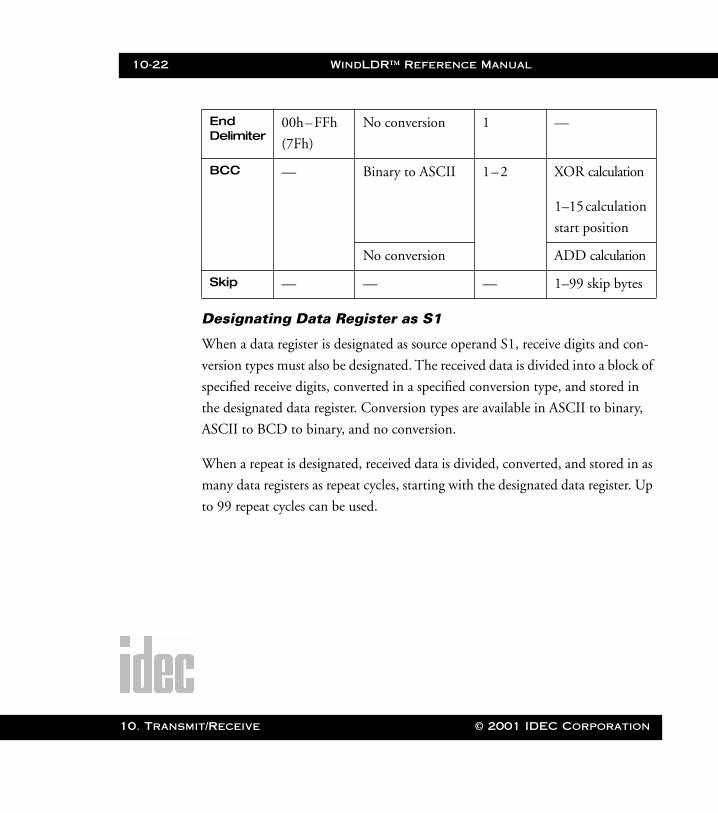
10-22 WindLDR™ Reference Manual
10. Transm
WLDR ReferenceBook Page 22 Thursday, April 5, 2001 3:36 PM
Designating Data Register as S1
When a data register is designated as source operand S1, receive digits and con-
version types must also be designated. The received data is divided into a block of
specified receive digits, converted in a specified conversion type, and stored in
the designated data register. Conversion types are available in ASCII to binary,
ASCII to BCD to binary, and no conversion.
When a repeat is designated, received data is divided, converted, and stored in as
many data registers as repeat cycles, starting with the designated data register. Up
to 99 repeat cycles can be used.
End Delimiter
00h–FFh
(7Fh)
No conversion 1 —
BCC — Binary to ASCII 1–2 XOR calculation
1–15 calculation
start position
No conversion ADD calculation
Skip — — — 1–99 skip bytes
it/Receive © 2001 IDEC Corporation
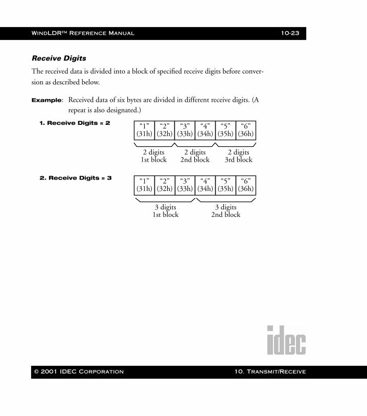
WindLDR™ Reference Manual 10-23
WLDR ReferenceBook Page 23 Thursday, April 5, 2001 3:36 PM
Receive Digits
The received data is divided into a block of specified receive digits before conver-
sion as described below.
Example: Received data of six bytes are divided in different receive digits. (A repeat is also designated.)
“3”(33h)
“4”(34h)
“5”(35h)
“6”(36h)
“1”(31h)
“2”(32h)
1. Receive Digits = 2
2 digits1st block
2 digits2nd block
2 digits3rd block
“3”(33h)
“4”(34h)
“5”(35h)
“6”(36h)
“1”(31h)
“2”(32h)
2. Receive Digits = 3
3 digits1st block
3 digits2nd block
© 2001 IDEC Corporation 10. Transmit/Receive
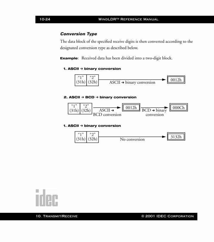
10-24 WindLDR™ Reference Manual
10. Transm
WLDR ReferenceBook Page 24 Thursday, April 5, 2001 3:36 PM
Conversion Type
The data block of the specified receive digits is then converted according to the
designated conversion type as described below.
Example: Received data has been divided into a two-digit block.
ASCII ➔ binary conversion
1. ASCII ➔ binary conversion
0012h“2”(32h)
“1”(31h)
ASCII ➔
2. ASCII ➔ BCD ➔ binary conversion
0012h“2”(32h)
“1”(31h) BCD ➔ binary
000Ch
BCD conversion conversion
No conversion
1. ASCII ➔ binary conversion
3132h“2”(32h)
“1”(31h)
it/Receive © 2001 IDEC Corporation
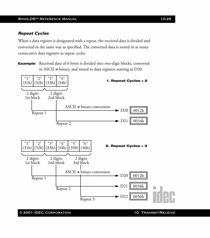
WindLDR™ Reference Manual 10-25
WLDR ReferenceBook Page 25 Thursday, April 5, 2001 3:36 PM
Repeat Cycles
When a data register is designated with a repeat, the received data is divided and
converted in the same way as specified. The converted data is stored in as many
consecutive data registers as repeat cycles.
Example: Received data of 6 bytes is divided into two-digit blocks, converted in ASCII ➔ binary, and stored to data registers starting at D20.
“3”(33h)
“4”(34h)
“1”(31h)
“2”(32h) 1. Repeat Cycles = 2
2 digits1st block
2 digits2nd block
D20 0012h
D21 0034h
Repeat 1
Repeat 2
ASCII ➔ binary conversion
2. Repeat Cycles = 3
D20 0012h
D21 0034h
Repeat 1
Repeat 2
“3”(33h)
“4”(34h)
“5”(35h)
“6”(36h)
“1”(31h)
“2”(32h)
2 digits1st block
2 digits2nd block
2 digits3rd block
D22 0056h
ASCII ➔ binary conversion
Repeat 3
© 2001 IDEC Corporation 10. Transmit/Receive

10-26 WindLDR™ Reference Manual
10. Transm
WLDR ReferenceBook Page 26 Thursday, April 5, 2001 3:36 PM
Designating a Constant as a Start Delimiter
A start delimiter can be programmed at the first byte in the receive format of an
RXD instruction. This way the Micro3C can recognize the beginning of valid
communication; although, an RXD instruction without a start delimiter can also
be executed.
When a constant value is designated at the first byte of source operand S1, the
one-byte data serves as a start delimiter to start the processing of the received
data. The valid start delimiter value depends on the data bits selected in the
FUN8 loader port communication mode setting. When eight data bits are
selected, start delimiters can be 00h–FFh. When seven data bits are selected as
default, start delimiters can be 00h–7Fh. Constant values are entered in hexa-
decimal notation into the source data.
A maximum of five RXD instructions with different start delimiters can be exe-
cuted at the same time. When the first byte of the incoming data matches the
start delimiter of an RXD instruction, the received data is processed and stored
according to the receive format specified in the RXD instruction. If the first byte
of the incoming data does not match the start delimiter of any RXD instruction
that is executed, the Micro3C discards the incoming data and waits for the next
communication.
While an RXD instruction without a start delimiter is executed, any incoming
data is processed continuously according to the receive format. Only one RXD
instruction without a start delimiter can be executed at a time. If start inputs to
two or more RXD instructions without a start delimiter are turned on simulta-
neously, then the one at the smallest address is executed and the corresponding
completion output is turned on.
it/Receive © 2001 IDEC Corporation

WindLDR™ Reference Manual 10-27
WLDR ReferenceBook Page 27 Thursday, April 5, 2001 3:36 PM
Designating a Constant as an End Delimiter
Program an end delimiter anywhere other than the first byte in the receive format
of an RXD instruction. The Micro3C will recognize the end of valid communi-
cation. Even so, RXD instructions without end delimiters can also be executed.
When a constant value is designated anywhere other than the first byte of source
operand S1, the one-byte data serves as an end delimiter to end the processing of
the received data. The valid end delimiter value depends on the data bits selected
in the FUN8 loader port communication mode setting. When eight data bits are
selected, end delimiters can be 00h–FFh. When seven data bits are selected as
the default, end delimiters can be 00h–7Fh. Constant values are entered in hexa-
decimal notation into the source data.
If a character in the incoming data matches the end delimiter, then the RXD
instruction stops receiving data at this point and starts the subsequent receive
processing as specified. Even if a character matches the end delimiter at a posi-
tion earlier than expected, the RXD instruction stops receiving data there.
If a BCC code is included in the receive format of an RXD instruction, then an
end delimiter can be positioned immediately before or after the BCC code. If a
data register or skip is designated between the BCC and the end delimiter, then
correct receiving is not ensured.
When an RXD instruction without an end delimiter is executed, data receiving
ends when the specified bytes of the data in the receive format, such as data regis-
ters and skips, have been received. In addition, data receiving ends when the
interval between the incoming data characters exceeds the receive time-out value
specified in the FUN8 loader port communication mode setting, whether the
RXD has an end delimiter or not.
© 2001 IDEC Corporation 10. Transmit/Receive
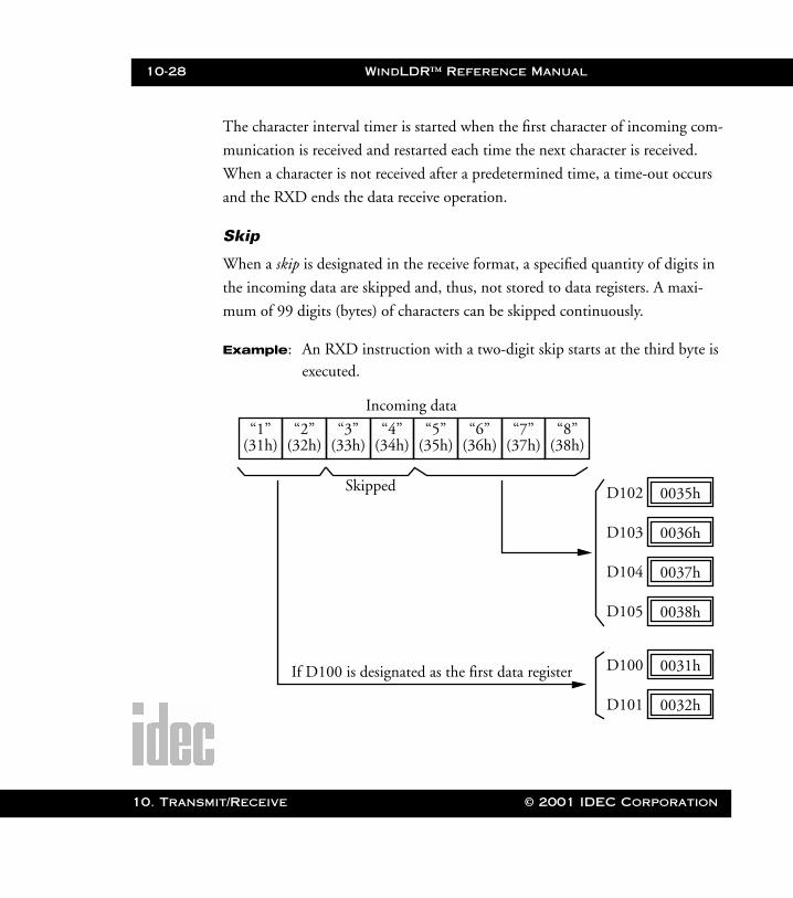
10-28 WindLDR™ Reference Manual
10. Transm
WLDR ReferenceBook Page 28 Thursday, April 5, 2001 3:36 PM
The character interval timer is started when the first character of incoming com-
munication is received and restarted each time the next character is received.
When a character is not received after a predetermined time, a time-out occurs
and the RXD ends the data receive operation.
Skip
When a skip is designated in the receive format, a specified quantity of digits in
the incoming data are skipped and, thus, not stored to data registers. A maxi-
mum of 99 digits (bytes) of characters can be skipped continuously.
Example: An RXD instruction with a two-digit skip starts at the third byte is executed.
D102 0035h
D103 0036h
“3”(33h)
“4”(34h)
“5”(35h)
“6”(36h)
“1”(31h)
“2”(32h)
D104 0037h
Incoming data
Skipped
If D100 is designated as the first data register
“7”(37h)
“8”(38h)
D105 0038h
D100 0031h
D101 0032h
it/Receive © 2001 IDEC Corporation
WindLDR™ Reference Manual 10-29
WLDR ReferenceBook Page 29 Thursday, April 5, 2001 3:36 PM
Block Check Character (BCC)
The Micro3C has an automatic BCC calculation function to detect any commu-
nication error in incoming data. If a BCC code is designated in the receive for-
mat of an RXD instruction, then the Micro3C calculates a BCC value for a
specified starting position through the position immediately preceding BCC. It
then compares the calculation result with the BCC code in the received incom-
ing data. The start position for the BCC calculation can be specified from the
first byte through fifteenth byte. The BCC, calculated in either XOR or ADD,
can be one or two digits.
When an end delimiter is not used in the RXD instruction, the BCC code must
be positioned at the end of the receive format designated in the Source 1 (S1)
operand. When an end delimiter is used, the BCC code must be immediately
before or after the end delimiter. The Micro3C reads a specified number of BCC
digits in the incoming data according to the receive format to calculate and com-
pare the received BCC code with the BCC calculation results.
BCC Calculation Start Position
The start position for the BCC calculation can be specified from the first byte
through fifteenth byte. The BCC is calculated for the range starting from the
designated position up to the byte immediately before the BCC of the receive
data.
© 2001 IDEC Corporation 10. Transmit/Receive
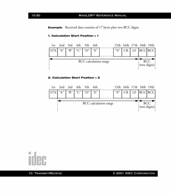
10-30 WindLDR™ Reference Manual
10. Transm
WLDR ReferenceBook Page 30 Thursday, April 5, 2001 3:36 PM
Example: Received data consists of 17 bytes plus two BCC digits.
1. Calculation Start Position = 1
2. Calculation Start Position = 2
STX
1st
“A”
2nd
“B”
3rd
“C”
4th
“D”
5th
“E”
6th
“0”
15th
CR
16th
LF
17th
BCC
18th
BCC
19th
BCC calculation range BCC(two digits)
STX
1st
“A”
2nd
“B”
3rd
“C”
4th
“D”
5th
“E”
6th
“0”
15th
CR
16th
LF
17th
BCC
18th
BCC
19th
BCC calculation range BCC(two digits)
it/Receive © 2001 IDEC Corporation
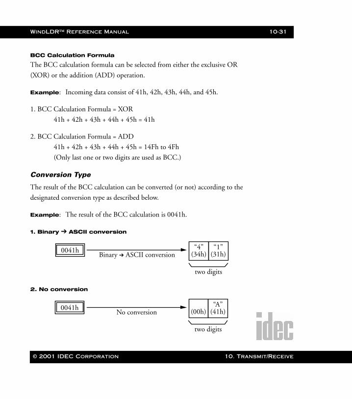
WindLDR™ Reference Manual 10-31
WLDR ReferenceBook Page 31 Thursday, April 5, 2001 3:36 PM
BCC Calculation Formula
The BCC calculation formula can be selected from either the exclusive OR
(XOR) or the addition (ADD) operation.
Example: Incoming data consist of 41h, 42h, 43h, 44h, and 45h.
1. BCC Calculation Formula = XOR
41h + 42h + 43h + 44h + 45h = 41h
2. BCC Calculation Formula = ADD
41h + 42h + 43h + 44h + 45h = 14Fh to 4Fh
(Only last one or two digits are used as BCC.)
Conversion Type
The result of the BCC calculation can be converted (or not) according to the
designated conversion type as described below.
Example: The result of the BCC calculation is 0041h.
1. Binary ➔ ASCII conversion
2. No conversion
Binary ➔ ASCII conversion0041h “4”
(34h)“1”
(31h)
two digits
No conversion0041h (00h)
“A”(41h)
two digits
© 2001 IDEC Corporation 10. Transmit/Receive
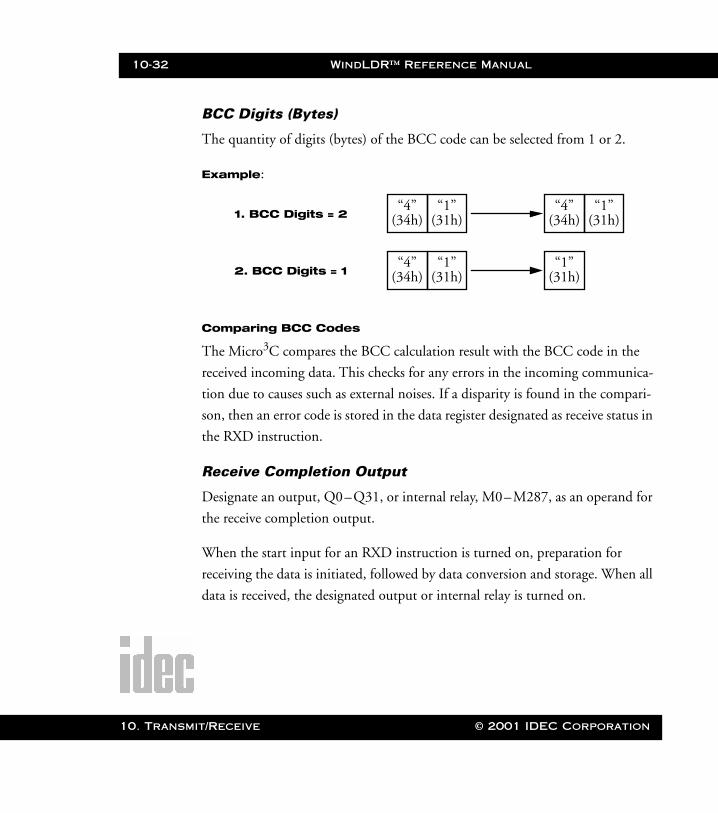
10-32 WindLDR™ Reference Manual
10. Transm
WLDR ReferenceBook Page 32 Thursday, April 5, 2001 3:36 PM
BCC Digits (Bytes)
The quantity of digits (bytes) of the BCC code can be selected from 1 or 2.
Example:
Comparing BCC Codes
The Micro3C compares the BCC calculation result with the BCC code in the
received incoming data. This checks for any errors in the incoming communica-
tion due to causes such as external noises. If a disparity is found in the compari-
son, then an error code is stored in the data register designated as receive status in
the RXD instruction.
Receive Completion Output
Designate an output, Q0–Q31, or internal relay, M0–M287, as an operand for
the receive completion output.
When the start input for an RXD instruction is turned on, preparation for
receiving the data is initiated, followed by data conversion and storage. When all
data is received, the designated output or internal relay is turned on.
“4”(34h)
“1”(31h)
“4”(34h)
“1”(31h)1. BCC Digits = 2
“4”(34h)
“1”(31h)
“1”(31h)2. BCC Digits = 1
it/Receive © 2001 IDEC Corporation
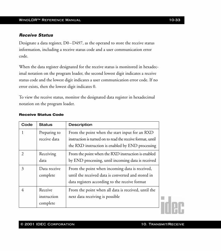
WindLDR™ Reference Manual 10-33
WLDR ReferenceBook Page 33 Thursday, April 5, 2001 3:36 PM
Receive Status
Designate a data register, D0–D497, as the operand to store the receive status
information, including a receive status code and a user communication error
code.
When the data register designated for the receive status is monitored in hexadec-
imal notation on the program loader, the second lowest digit indicates a receive
status code and the lowest digit indicates a user communication error code. If no
error exists, then the lowest digit indicates 0.
To view the receive status, monitor the designated data register in hexadecimal
notation on the program loader.
Receive Status Code
Code Status Description
1 Preparing to
receive data
From the point when the start input for an RXD
instruction is turned on to read the receive format, until
the RXD instruction is enabled by END processing
2 Receiving
data
From the point when the RXD instruction is enabled
by END processing, until incoming data is received
3 Data receive
complete
From the point when incoming data is received,
until the received data is converted and stored in
data registers according to the receive format
4 Receive
instruction
complete
From the point when all data is received, until the
next data receiving is possible
© 2001 IDEC Corporation 10. Transmit/Receive
10-34 WindLDR™ Reference Manual
10. Transm
WLDR ReferenceBook Page 34 Thursday, April 5, 2001 3:36 PM
If data receiving is aborted by an error, then remove the cause of the error and
turn the start input for the RXD instruction on again. For error codes and
causes, refer to Appendix III: PLC Error Codes.
Receive Data Byte Count
The data register following the operand designated for the receive status stores
the byte count of the data received by the RXD instruction. When a start delim-
iter, end delimiter, and BCC are included in the received data, the byte counts
for these codes are also included in the receive data byte count.
it/Receive © 2001 IDEC Corporation

© 2001 IDEC Corpora
WLDR ReferenceBook Page 1 Thursday, April 5, 2001 3:36 PM
Appendix 1: Allocation Numbers
Micro-1 PLC
Allocation Table
NOTE: Outputs Q006–Q007 (two points) cannot be used.
Outputs Q010–Q015 (six points) can be used with the expansion unit.
Outputs Q010–Q017 (eight points) can be used with the serial I/O module.
Special internal relays (M200–M287) are used for key matrix operations.
Operand Symbolic Total Points
Adding Counter C000–C044 45
Input I000–I017 16
Internal Relay M000–M197 160
Output Q000–Q005, Q010–Q017 14
Reversible Counter C045–C046 2
Shift Register R000–R127 128
Single Output 0–95 96
Special Internal Relay M200–M297, M300–M317 96
Timer T000–T097 80
tion Appendix 1: Allocation Numbers
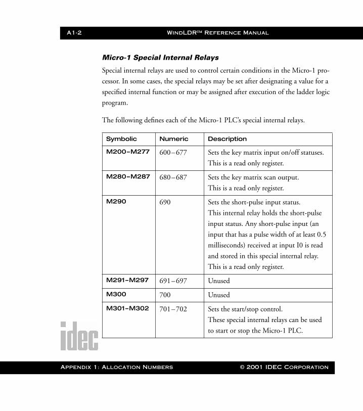
A1-2 WindLDR™ Reference Manual
Appendix 1
WLDR ReferenceBook Page 2 Thursday, April 5, 2001 3:36 PM
Micro-1 Special Internal Relays
Special internal relays are used to control certain conditions in the Micro-1 pro-
cessor. In some cases, the special relays may be set after designating a value for a
specified internal function or may be assigned after execution of the ladder logic
program.
The following defines each of the Micro-1 PLC’s special internal relays.
Symbolic Numeric Description
M200–M277 600–677 Sets the key matrix input on/off statuses.
This is a read only register.
M280–M287 680–687 Sets the key matrix scan output.
This is a read only register.
M290 690 Sets the short-pulse input status.
This internal relay holds the short-pulse
input status. Any short-pulse input (an
input that has a pulse width of at least 0.5
milliseconds) received at input I0 is read
and stored in this special internal relay.
This is a read only register.
M291–M297 691–697 Unused
M300 700 Unused
M301–M302 701–702 Sets the start/stop control.
These special internal relays can be used
to start or stop the Micro-1 PLC.
: Allocation Numbers © 2001 IDEC Corporation
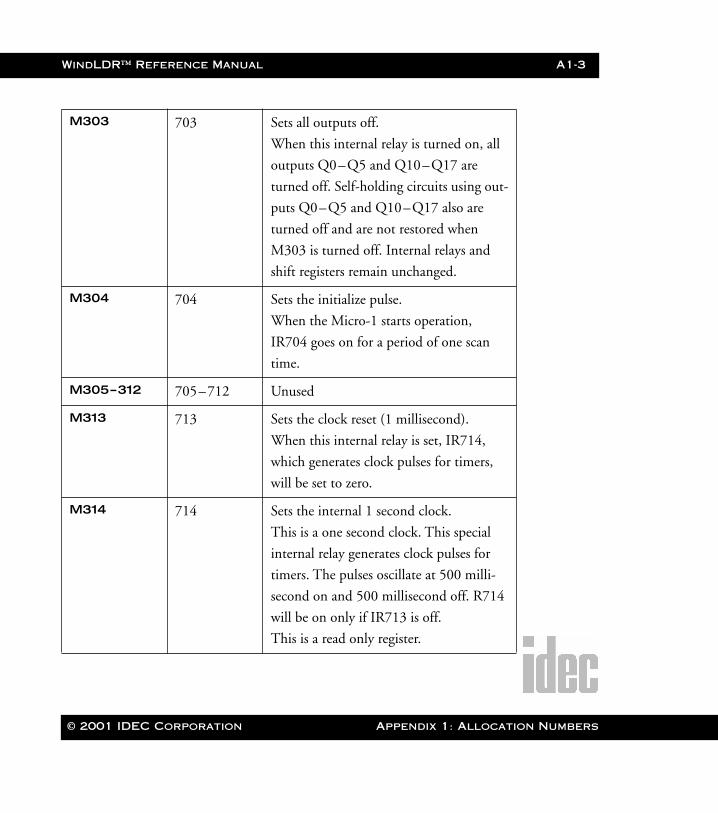
WindLDR™ Reference Manual A1-3
WLDR ReferenceBook Page 3 Thursday, April 5, 2001 3:36 PM
M303 703 Sets all outputs off.
When this internal relay is turned on, all
outputs Q0–Q5 and Q10–Q17 are
turned off. Self-holding circuits using out-
puts Q0–Q5 and Q10–Q17 also are
turned off and are not restored when
M303 is turned off. Internal relays and
shift registers remain unchanged.
M304 704 Sets the initialize pulse.
When the Micro-1 starts operation,
IR704 goes on for a period of one scan
time.
M305–312 705–712 Unused
M313 713 Sets the clock reset (1 millisecond).
When this internal relay is set, IR714,
which generates clock pulses for timers,
will be set to zero.
M314 714 Sets the internal 1 second clock.
This is a one second clock. This special
internal relay generates clock pulses for
timers. The pulses oscillate at 500 milli-
second on and 500 millisecond off. R714
will be on only if IR713 is off.
This is a read only register.
© 2001 IDEC Corporation Appendix 1: Allocation Numbers
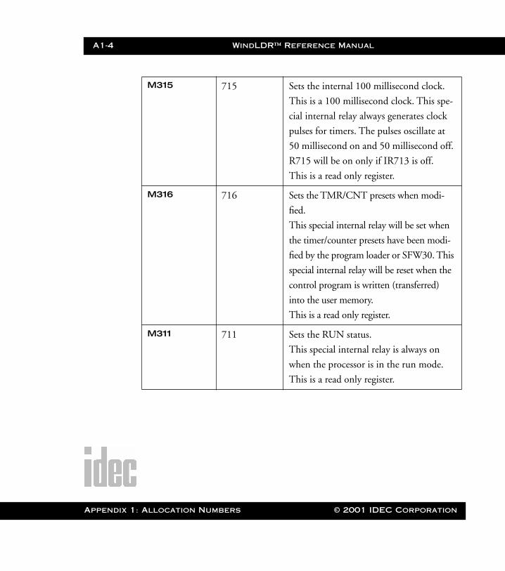
A1-4 WindLDR™ Reference Manual
Appendix 1
WLDR ReferenceBook Page 4 Thursday, April 5, 2001 3:36 PM
M315 715 Sets the internal 100 millisecond clock.
This is a 100 millisecond clock. This spe-
cial internal relay always generates clock
pulses for timers. The pulses oscillate at
50 millisecond on and 50 millisecond off.
R715 will be on only if IR713 is off.
This is a read only register.
M316 716 Sets the TMR/CNT presets when modi-
fied.
This special internal relay will be set when
the timer/counter presets have been modi-
fied by the program loader or SFW30. This
special internal relay will be reset when the
control program is written (transferred)
into the user memory.
This is a read only register.
M311 711 Sets the RUN status.
This special internal relay is always on
when the processor is in the run mode.
This is a read only register.
: Allocation Numbers © 2001 IDEC Corporation
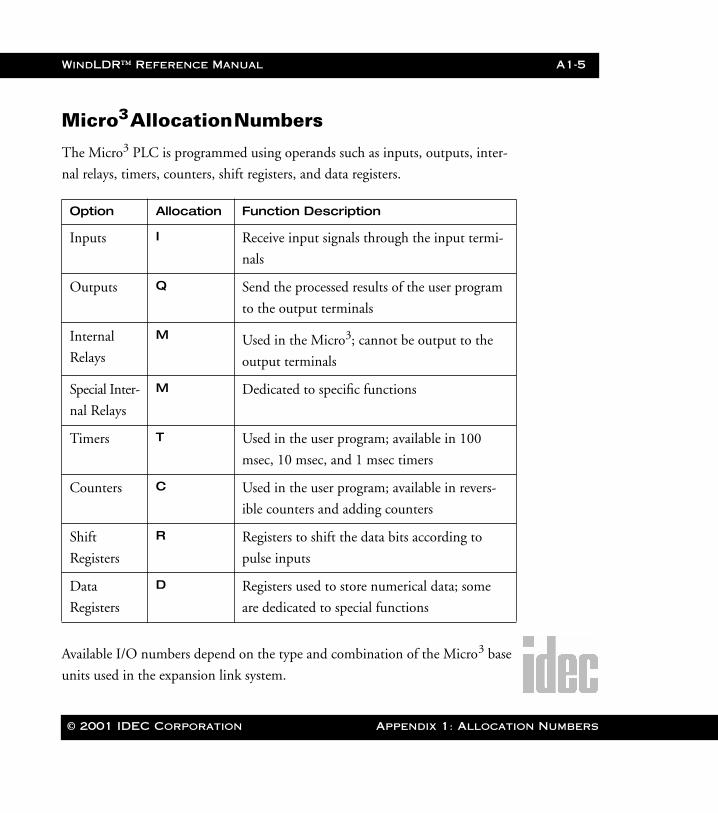
WindLDR™ Reference Manual A1-5
WLDR ReferenceBook Page 5 Thursday, April 5, 2001 3:36 PM
Micro3 Allocation Numbers
The Micro3 PLC is programmed using operands such as inputs, outputs, inter-
nal relays, timers, counters, shift registers, and data registers.
Available I/O numbers depend on the type and combination of the Micro3 base
units used in the expansion link system.
Option Allocation Function Description
Inputs I Receive input signals through the input termi-
nals
Outputs Q Send the processed results of the user program
to the output terminals
Internal
Relays
M Used in the Micro3; cannot be output to the
output terminals
Special Inter-
nal Relays
M Dedicated to specific functions
Timers T Used in the user program; available in 100
msec, 10 msec, and 1 msec timers
Counters C Used in the user program; available in revers-
ible counters and adding counters
Shift
Registers
R Registers to shift the data bits according to
pulse inputs
Data
Registers
D Registers used to store numerical data; some
are dedicated to special functions
© 2001 IDEC Corporation Appendix 1: Allocation Numbers
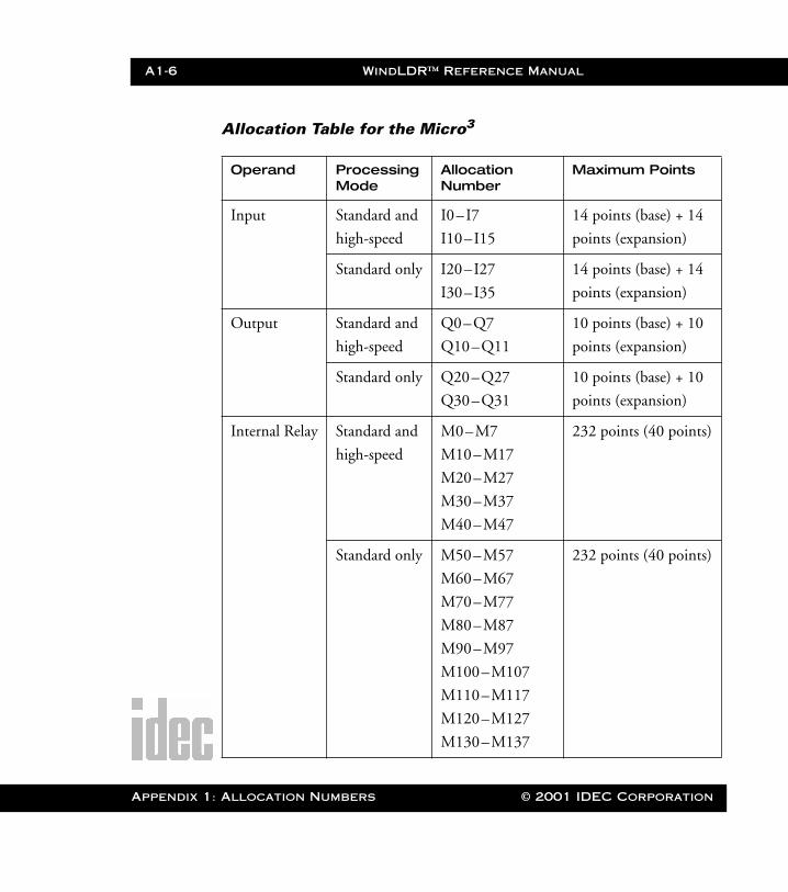
A1-6 WindLDR™ Reference Manual
Appendix 1
WLDR ReferenceBook Page 6 Thursday, April 5, 2001 3:36 PM
Allocation Table for the Micro3
Operand Processing Mode
Allocation Number
Maximum Points
Input Standard and
high-speed
I0–I7
I10–I15
14 points (base) + 14
points (expansion)
Standard only I20–I27
I30–I35
14 points (base) + 14
points (expansion)
Output Standard and
high-speed
Q0–Q7
Q10–Q11
10 points (base) + 10
points (expansion)
Standard only Q20–Q27
Q30–Q31
10 points (base) + 10
points (expansion)
Internal Relay Standard and
high-speed
M0–M7
M10–M17
M20–M27
M30–M37
M40–M47
232 points (40 points)
Standard only M50–M57
M60–M67
M70–M77
M80–M87
M90–M97
M100–M107
M110–M117
M120–M127
M130–M137
232 points (40 points)
: Allocation Numbers © 2001 IDEC Corporation
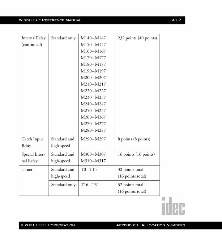
WindLDR™ Reference Manual A1-7
WLDR ReferenceBook Page 7 Thursday, April 5, 2001 3:36 PM
Internal Relay
(continued)
Standard only M140–M147
M150–M157
M160–M167
M170–M177
M180–M187
M190–M197
M200–M207
M210–M217
M220–M227
M230–M237
M240–M247
M250–M257
M260–M267
M270–M277
M280–M287
232 points (40 points)
Catch Input
Relay
Standard and
high-speed
M290–M297 8 points (8 points)
Special Inter-
nal Relay
Standard and
high-speed
M300–M307
M310–M317
16 points (16 points)
Timer Standard and
high-speed
T0–T15 32 points total
(16 points total)
Standard only T16–T31 32 points total
(16 points total)
© 2001 IDEC Corporation Appendix 1: Allocation Numbers
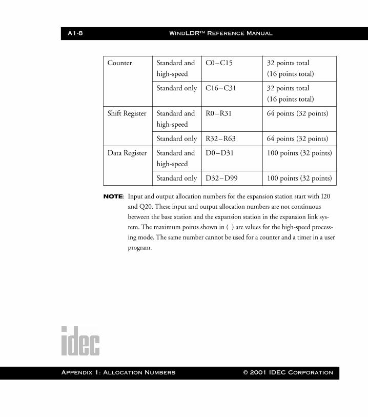
A1-8 WindLDR™ Reference Manual
Appendix 1
WLDR ReferenceBook Page 8 Thursday, April 5, 2001 3:36 PM
NOTE: Input and output allocation numbers for the expansion station start with I20
and Q20. These input and output allocation numbers are not continuous
between the base station and the expansion station in the expansion link sys-
tem. The maximum points shown in ( ) are values for the high-speed process-
ing mode. The same number cannot be used for a counter and a timer in a user
program.
Counter Standard and
high-speed
C0–C15 32 points total
(16 points total)
Standard only C16–C31 32 points total
(16 points total)
Shift Register Standard and
high-speed
R0–R31 64 points (32 points)
Standard only R32–R63 64 points (32 points)
Data Register Standard and
high-speed
D0–D31 100 points (32 points)
Standard only D32–D99 100 points (32 points)
: Allocation Numbers © 2001 IDEC Corporation

WindLDR™ Reference Manual A1-9
WLDR ReferenceBook Page 9 Thursday, April 5, 2001 3:36 PM
Micro3 Special Internal Relays
IR Number Function Description
M301 Initialize
PulseWhen Micro3 starts operation, M301 turns
on for a period of one scan.
M302 All Outputs
OFF
When M302 is turned on, all outputs
(Q0 – Q31) go off until M302 is turned off.
Self-maintaining circuits using outputs also
go off and are not restored when M302 is
turned off.
M303 Carry (Cy)
and
Borrow (Bw)
When a carry or borrow results from exe-
cuting an addition or subtraction instruc-
tion, M303 turns on. M303 is also used for
the bit shift and rotate instructions.
M304 User Program
Execution
Error
When an error occurs while executing a
user program, M304 turns on.
M305 Link Com-
munication
Error
When an error occurs during communica-
tion in the expansion link system or in the
data link system, M305 turns on. The
M305 status is maintained when the error is
cleared and remains on until M305 is reset
using the program loader.
© 2001 IDEC Corporation Appendix 1: Allocation Numbers
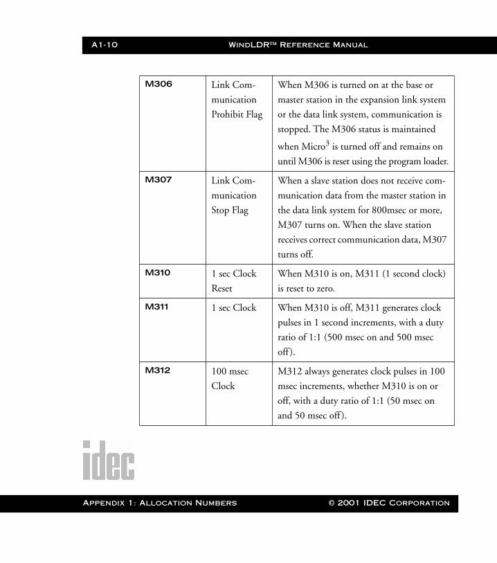
A1-10 WindLDR™ Reference Manual
Appendix 1
WLDR ReferenceBook Page 10 Thursday, April 5, 2001 3:36 PM
M306 Link Com-
munication
Prohibit Flag
When M306 is turned on at the base or
master station in the expansion link system
or the data link system, communication is
stopped. The M306 status is maintained
when Micro3 is turned off and remains on
until M306 is reset using the program loader.
M307 Link Com-
munication
Stop Flag
When a slave station does not receive com-
munication data from the master station in
the data link system for 800msec or more,
M307 turns on. When the slave station
receives correct communication data, M307
turns off.
M310 1 sec Clock
Reset
When M310 is on, M311 (1 second clock)
is reset to zero.
M311 1 sec Clock When M310 is off, M311 generates clock
pulses in 1 second increments, with a duty
ratio of 1:1 (500 msec on and 500 msec
off ).
M312 100 msec
Clock
M312 always generates clock pulses in 100
msec increments, whether M310 is on or
off, with a duty ratio of 1:1 (50 msec on
and 50 msec off ).
: Allocation Numbers © 2001 IDEC Corporation
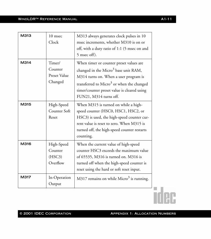
WindLDR™ Reference Manual A1-11
WLDR ReferenceBook Page 11 Thursday, April 5, 2001 3:36 PM
M313 10 msec
Clock
M313 always generates clock pulses in 10
msec increments, whether M310 is on or
off, with a duty ratio of 1:1 (5 msec on and
5 msec off ).
M314 Timer/
Counter
Preset Value
Changed
When timer or counter preset values are
changed in the Micro3 base unit RAM,
M314 turns on. When a user program is
transferred to Micro3 or when the changed
timer/counter preset value is cleared using
FUN21, M314 turns off.
M315 High-Speed
Counter Soft
Reset
When M315 is turned on while a high-
speed counter (HSC0, HSC1, HSC2, or
HSC3) is used, the high-speed counter cur-
rent value is reset to zero. When M315 is
turned off, the high-speed counter restarts
counting.
M316 High-Speed
Counter
(HSC3)
Overflow
When the current value of high-speed
counter HSC3 exceeds the maximum value
of 65535, M316 is turned on. M316 is
turned off when the high-speed counter is
reset using the hard or soft reset input.
M317 In-Operation
OutputM317 remains on while Micro3 is running.
© 2001 IDEC Corporation Appendix 1: Allocation Numbers
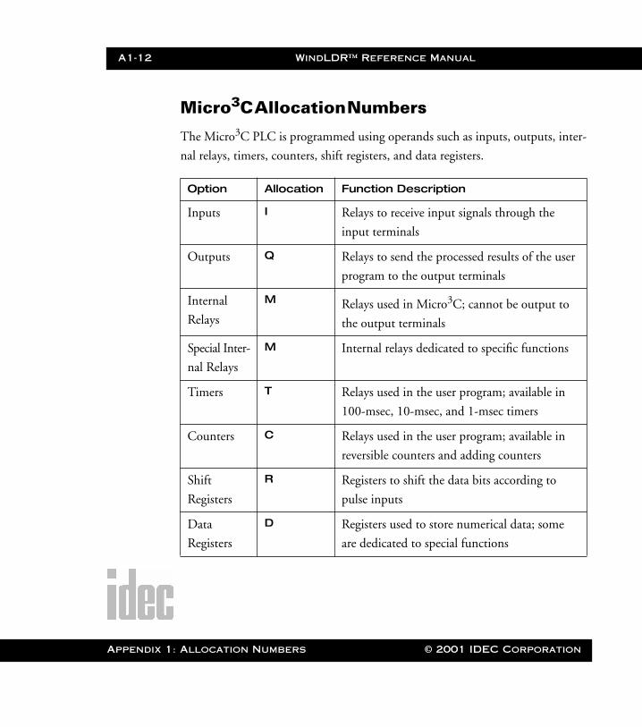
A1-12 WindLDR™ Reference Manual
Appendix 1
WLDR ReferenceBook Page 12 Thursday, April 5, 2001 3:36 PM
Micro3C Allocation Numbers
The Micro3C PLC is programmed using operands such as inputs, outputs, inter-
nal relays, timers, counters, shift registers, and data registers.
Option Allocation Function Description
Inputs I Relays to receive input signals through the
input terminals
Outputs Q Relays to send the processed results of the user
program to the output terminals
Internal
Relays
M Relays used in Micro3C; cannot be output to
the output terminals
Special Inter-
nal Relays
M Internal relays dedicated to specific functions
Timers T Relays used in the user program; available in
100-msec, 10-msec, and 1-msec timers
Counters C Relays used in the user program; available in
reversible counters and adding counters
Shift
Registers
R Registers to shift the data bits according to
pulse inputs
Data
Registers
D Registers used to store numerical data; some
are dedicated to special functions
: Allocation Numbers © 2001 IDEC Corporation
WindLDR™ Reference Manual A1-13
WLDR ReferenceBook Page 13 Thursday, April 5, 2001 3:36 PM
This section describes allocation numbers available only for Micro3C. For details
about allocation numbers shared with the Micro3, refer to the Allocation Table for
the Micro3 on page A1- 6. The expanded functions available with the Micro3C
include:
• The Micro3C has 500 data registers: D0–D499• D499 is used to enable or disable the expansion control data registers
D484–D498 and cannot be used as an ordinary data register to store data • Special internal relay M307 has different functions when used as a base or
expansion station in the expansion link system or when used as a master sta-tion or slave station in the data link system
Available I/O numbers depend on the type and combination of the Micro3C
base units used in the expansion link system.
© 2001 IDEC Corporation Appendix 1: Allocation Numbers
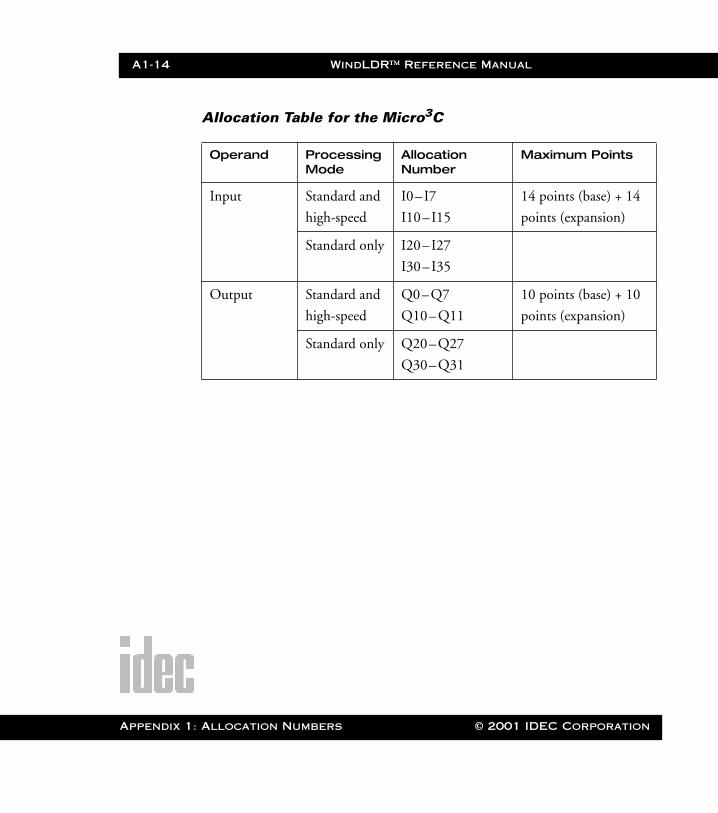
A1-14 WindLDR™ Reference Manual
Appendix 1
WLDR ReferenceBook Page 14 Thursday, April 5, 2001 3:36 PM
Allocation Table for the Micro3C
Operand Processing Mode
Allocation Number
Maximum Points
Input Standard and
high-speed
I0–I7
I10–I15
14 points (base) + 14
points (expansion)
Standard only I20–I27
I30–I35
Output Standard and
high-speed
Q0–Q7
Q10–Q11
10 points (base) + 10
points (expansion)
Standard only Q20–Q27
Q30–Q31
: Allocation Numbers © 2001 IDEC Corporation
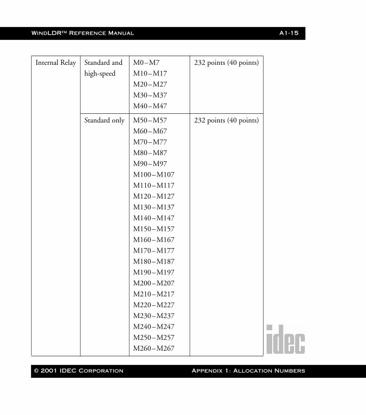
WindLDR™ Reference Manual A1-15
WLDR ReferenceBook Page 15 Thursday, April 5, 2001 3:36 PM
Internal Relay Standard and
high-speed
M0–M7
M10–M17
M20–M27
M30–M37
M40–M47
232 points (40 points)
Standard only M50–M57
M60–M67
M70–M77
M80–M87
M90–M97
M100–M107
M110–M117
M120–M127
M130–M137
M140–M147
M150–M157
M160–M167
M170–M177
M180–M187
M190–M197
M200–M207
M210–M217
M220–M227
M230–M237
M240–M247
M250–M257
M260–M267
232 points (40 points)
© 2001 IDEC Corporation Appendix 1: Allocation Numbers
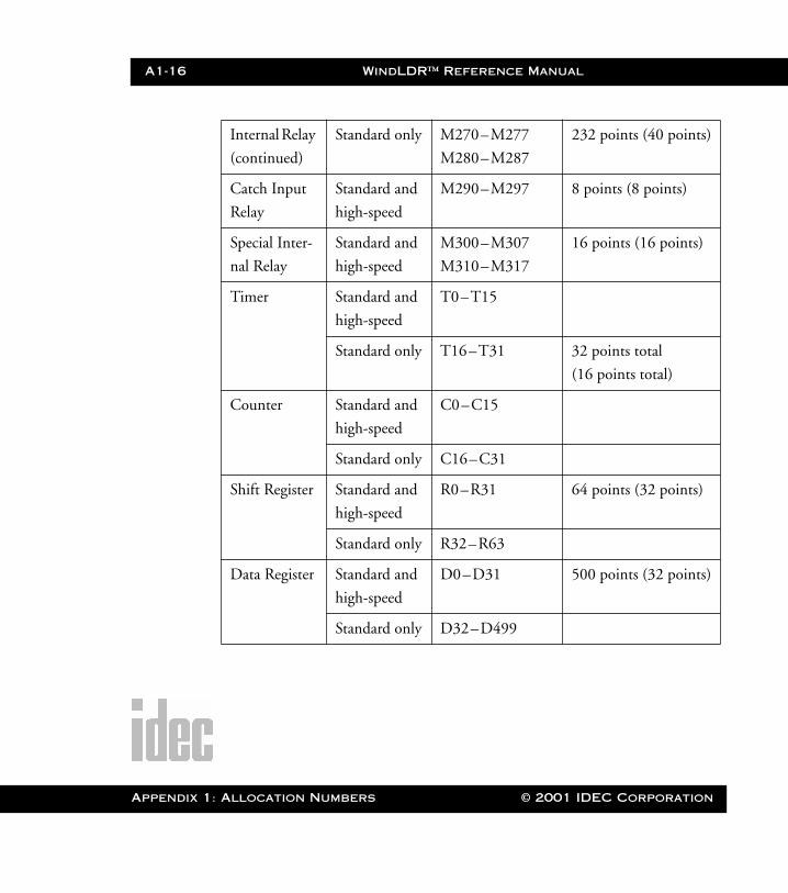
A1-16 WindLDR™ Reference Manual
Appendix 1
WLDR ReferenceBook Page 16 Thursday, April 5, 2001 3:36 PM
Internal Relay
(continued)
Standard only M270–M277
M280–M287
232 points (40 points)
Catch Input
Relay
Standard and
high-speed
M290–M297 8 points (8 points)
Special Inter-
nal Relay
Standard and
high-speed
M300–M307
M310–M317
16 points (16 points)
Timer Standard and
high-speed
T0–T15
Standard only T16–T31 32 points total
(16 points total)
Counter Standard and
high-speed
C0–C15
Standard only C16–C31
Shift Register Standard and
high-speed
R0–R31 64 points (32 points)
Standard only R32–R63
Data Register Standard and
high-speed
D0–D31 500 points (32 points)
Standard only D32–D499
: Allocation Numbers © 2001 IDEC Corporation
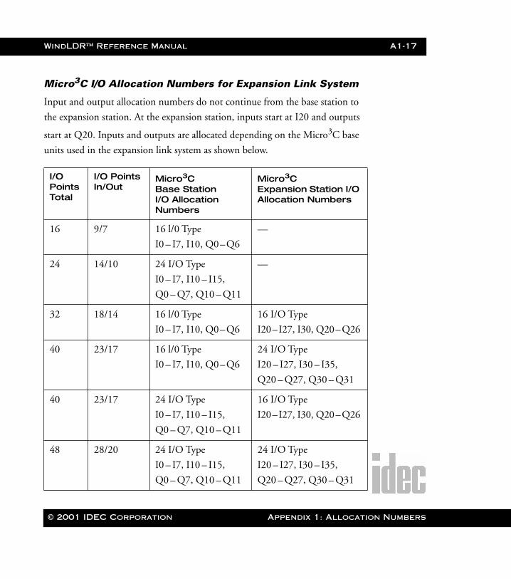
WindLDR™ Reference Manual A1-17
WLDR ReferenceBook Page 17 Thursday, April 5, 2001 3:36 PM
Micro3C I/O Allocation Numbers for Expansion Link System
Input and output allocation numbers do not continue from the base station to
the expansion station. At the expansion station, inputs start at I20 and outputs
start at Q20. Inputs and outputs are allocated depending on the Micro3C base
units used in the expansion link system as shown below.
I/O Points Total
I/O Points In/Out
Micro3C Base Station I/O Allocation Numbers
Micro3C Expansion Station I/O Allocation Numbers
16 9/7 16 l/0 Type
I0 – I7, I10, Q0–Q6
—
24 14/10 24 I/O Type
I0 – I7, I10 – I15,
Q0 – Q7, Q10 – Q11
—
32 18/14 16 l/0 Type
I0 – I7, I10, Q0–Q6
16 I/O Type
I20–I27, I30, Q20–Q26
40 23/17 16 l/0 Type
I0 – I7, I10, Q0–Q6
24 I/O Type
I20 – I27, I30 – I35,
Q20 – Q27, Q30 – Q31
40 23/17 24 I/O Type
I0 – I7, I10 – I15,
Q0 – Q7, Q10 – Q11
16 I/O Type
I20–I27, I30, Q20–Q26
48 28/20 24 I/O Type
I0 – I7, I10 – I15,
Q0 – Q7, Q10 – Q11
24 I/O Type
I20 – I27, I30 – I35,
Q20 – Q27, Q30 – Q31
© 2001 IDEC Corporation Appendix 1: Allocation Numbers
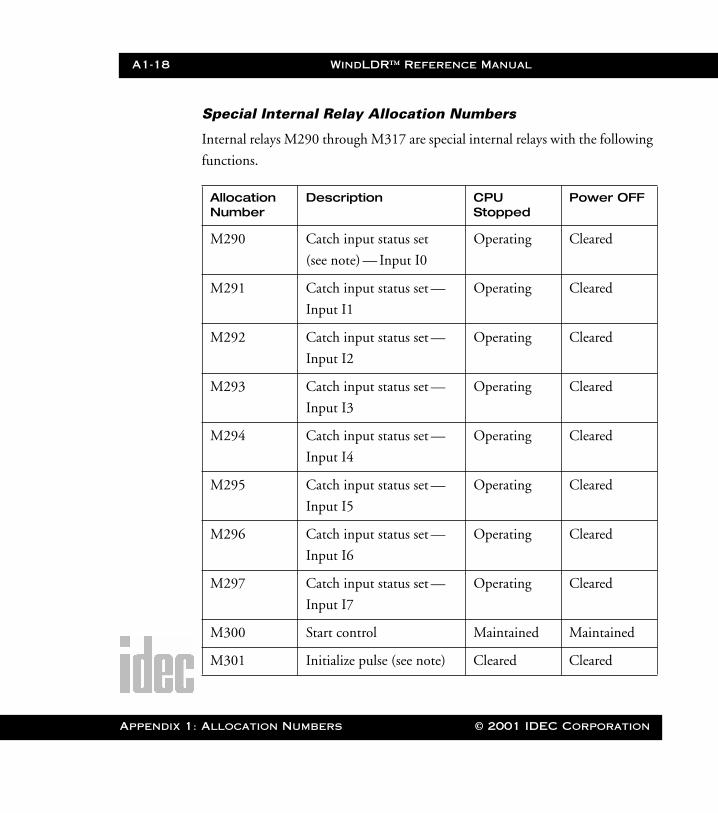
A1-18 WindLDR™ Reference Manual
Appendix 1
WLDR ReferenceBook Page 18 Thursday, April 5, 2001 3:36 PM
Special Internal Relay Allocation Numbers
Internal relays M290 through M317 are special internal relays with the following
functions.
Allocation Number
Description CPU Stopped
Power OFF
M290 Catch input status set
(see note) — Input I0
Operating Cleared
M291 Catch input status set —
Input I1
Operating Cleared
M292 Catch input status set —
Input I2
Operating Cleared
M293 Catch input status set —
Input I3
Operating Cleared
M294 Catch input status set —
Input I4
Operating Cleared
M295 Catch input status set —
Input I5
Operating Cleared
M296 Catch input status set —
Input I6
Operating Cleared
M297 Catch input status set —
Input I7
Operating Cleared
M300 Start control Maintained Maintained
M301 Initialize pulse (see note) Cleared Cleared
: Allocation Numbers © 2001 IDEC Corporation
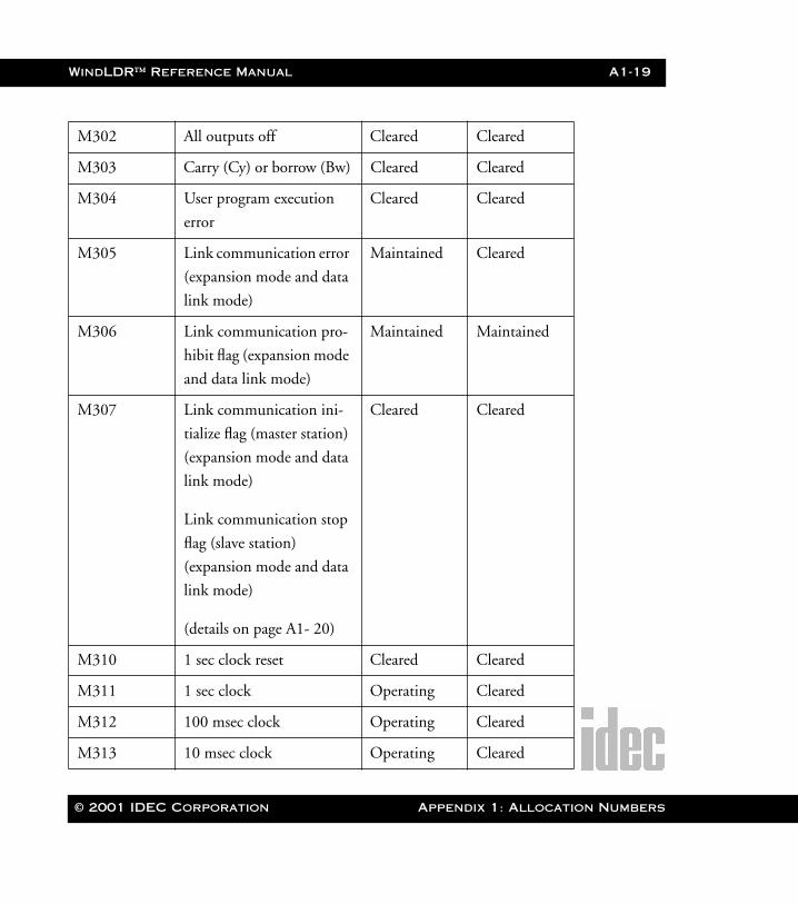
WindLDR™ Reference Manual A1-19
WLDR ReferenceBook Page 19 Thursday, April 5, 2001 3:36 PM
M302 All outputs off Cleared Cleared
M303 Carry (Cy) or borrow (Bw) Cleared Cleared
M304 User program execution
error
Cleared Cleared
M305 Link communication error
(expansion mode and data
link mode)
Maintained Cleared
M306 Link communication pro-
hibit flag (expansion mode
and data link mode)
Maintained Maintained
M307 Link communication ini-
tialize flag (master station)
(expansion mode and data
link mode)
Link communication stop
flag (slave station)
(expansion mode and data
link mode)
(details on page A1- 20)
Cleared Cleared
M310 1 sec clock reset Cleared Cleared
M311 1 sec clock Operating Cleared
M312 100 msec clock Operating Cleared
M313 10 msec clock Operating Cleared
© 2001 IDEC Corporation Appendix 1: Allocation Numbers
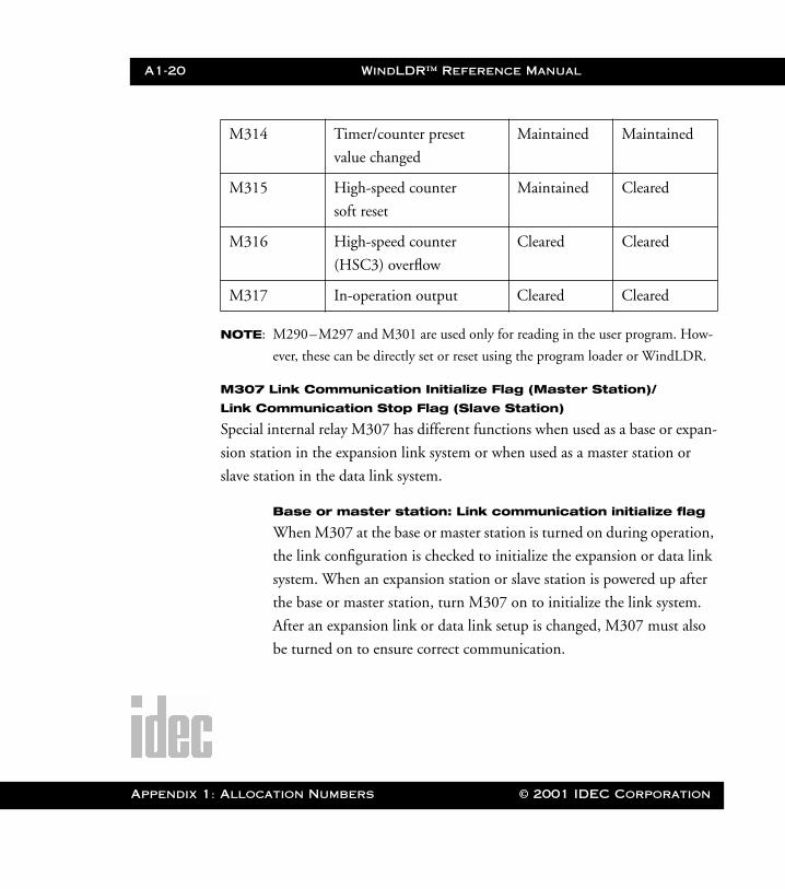
A1-20 WindLDR™ Reference Manual
Appendix 1
WLDR ReferenceBook Page 20 Thursday, April 5, 2001 3:36 PM
NOTE: M290–M297 and M301 are used only for reading in the user program. How-
ever, these can be directly set or reset using the program loader or WindLDR.
M307 Link Communication Initialize Flag (Master Station)/
Link Communication Stop Flag (Slave Station)
Special internal relay M307 has different functions when used as a base or expan-
sion station in the expansion link system or when used as a master station or
slave station in the data link system.
Base or master station: Link communication initialize flag
When M307 at the base or master station is turned on during operation,
the link configuration is checked to initialize the expansion or data link
system. When an expansion station or slave station is powered up after
the base or master station, turn M307 on to initialize the link system.
After an expansion link or data link setup is changed, M307 must also
be turned on to ensure correct communication.
M314 Timer/counter preset
value changed
Maintained Maintained
M315 High-speed counter
soft reset
Maintained Cleared
M316 High-speed counter
(HSC3) overflow
Cleared Cleared
M317 In-operation output Cleared Cleared
: Allocation Numbers © 2001 IDEC Corporation
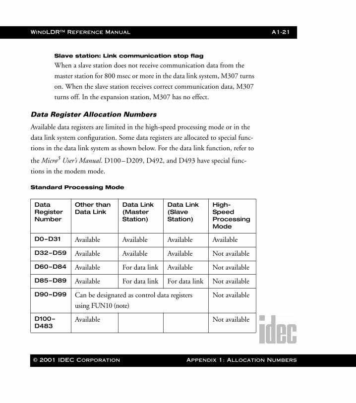
WindLDR™ Reference Manual A1-21
WLDR ReferenceBook Page 21 Thursday, April 5, 2001 3:36 PM
Slave station: Link communication stop flag
When a slave station does not receive communication data from the
master station for 800 msec or more in the data link system, M307 turns
on. When the slave station receives correct communication data, M307
turns off. In the expansion station, M307 has no effect.
Data Register Allocation Numbers
Available data registers are limited in the high-speed processing mode or in the
data link system configuration. Some data registers are allocated to special func-
tions in the data link system as shown below. For the data link function, refer to
the Micro3 User’s Manual. D100–D209, D492, and D493 have special func-
tions in the modem mode.
Standard Processing Mode
Data Register Number
Other than Data Link
Data Link (Master Station)
Data Link (Slave Station)
High-Speed Processing Mode
D0–D31 Available Available Available Available
D32–D59 Available Available Available Not available
D60–D84 Available For data link Available Not available
D85–D89 Available For data link For data link Not available
D90–D99 Can be designated as control data registers
using FUN10 (note)
Not available
D100–D483
Available Not available
© 2001 IDEC Corporation Appendix 1: Allocation Numbers
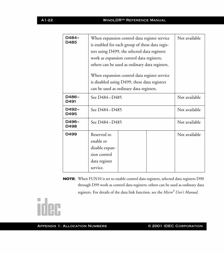
A1-22 WindLDR™ Reference Manual
Appendix 1
WLDR ReferenceBook Page 22 Thursday, April 5, 2001 3:36 PM
NOTE: When FUN10 is set to enable control data registers, selected data registers D90
through D99 work as control data registers; others can be used as ordinary data
registers. For details of the data link function, see the Micro3 User’s Manual.
D484–D485
When expansion control data register service
is enabled for each group of these data regis-
ters using D499, the selected data registers
work as expansion control data registers;
others can be used as ordinary data registers.
When expansion control data register service
is disabled using D499, these data registers
can be used as ordinary data registers.
Not available
D486–D491
See D484–D485 Not available
D492–D495
See D484–D485 Not available
D496–D498
See D484–D485 Not available
D499 Reserved to
enable or
disable expan-
sion control
data register
service.
Not available
: Allocation Numbers © 2001 IDEC Corporation
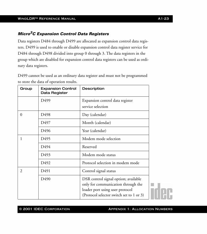
WindLDR™ Reference Manual A1-23
WLDR ReferenceBook Page 23 Thursday, April 5, 2001 3:36 PM
Micro3C Expansion Control Data Registers
Data registers D484 through D499 are allocated as expansion control data regis-
ters. D499 is used to enable or disable expansion control data register service for
D484 through D498 divided into group 0 through 3. The data registers in the
group which are disabled for expansion control data registers can be used as ordi-
nary data registers.
D499 cannot be used as an ordinary data register and must not be programmed
to store the data of operation results.
Group Expansion Control Data Register
Description
D499 Expansion control data register
service selection
0 D498 Day (calendar)
D497 Month (calendar)
D496 Year (calendar)
1 D495 Modem mode selection
D494 Reserved
D493 Modem mode status
D492 Protocol selection in modem mode
2 D491 Control signal status
D490 DSR control signal option; available only for communication through the loader port using user protocol (Protocol selector switch set to 1 or 3)
© 2001 IDEC Corporation Appendix 1: Allocation Numbers
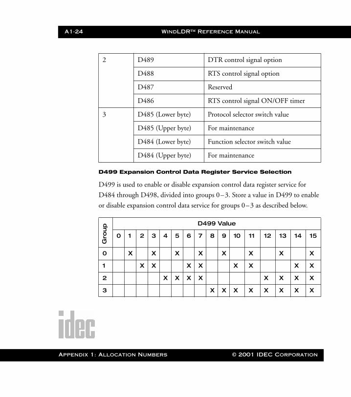
A1-24 WindLDR™ Reference Manual
Appendix 1
WLDR ReferenceBook Page 24 Thursday, April 5, 2001 3:36 PM
D499 Expansion Control Data Register Service Selection
D499 is used to enable or disable expansion control data register service for
D484 through D498, divided into groups 0–3. Store a value in D499 to enable
or disable expansion control data service for groups 0–3 as described below.
2 D489 DTR control signal option
D488 RTS control signal option
D487 Reserved
D486 RTS control signal ON/OFF timer
3 D485 (Lower byte) Protocol selector switch value
D485 (Upper byte) For maintenance
D484 (Lower byte) Function selector switch value
D484 (Upper byte) For maintenance
D499 Value
0 1 2 3 4 5 6 7 8 9 10 11 12 13 14 15
0 X X X X X X X X
1 X X X X X X X X
2 X X X X X X X X
3 X X X X X X X X
Gro
up
: Allocation Numbers © 2001 IDEC Corporation
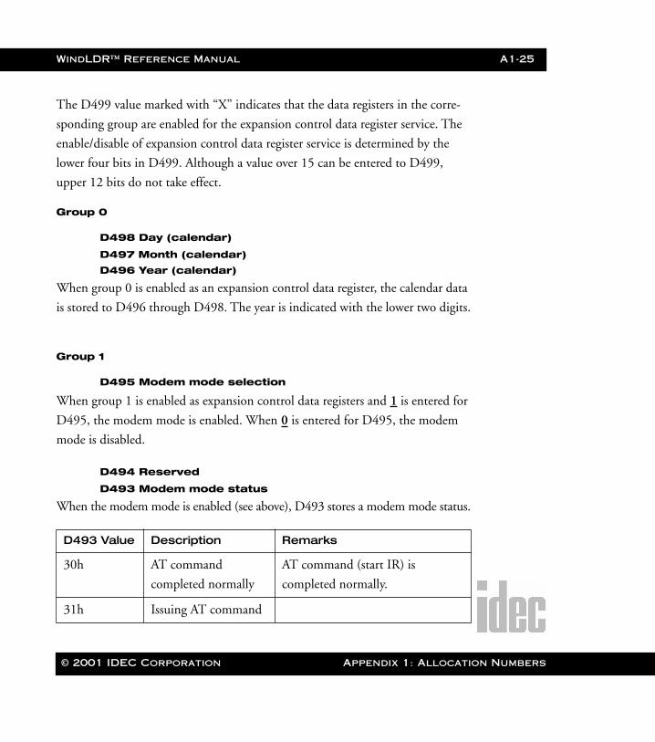
WindLDR™ Reference Manual A1-25
WLDR ReferenceBook Page 25 Thursday, April 5, 2001 3:36 PM
The D499 value marked with “X” indicates that the data registers in the corre-
sponding group are enabled for the expansion control data register service. The
enable/disable of expansion control data register service is determined by the
lower four bits in D499. Although a value over 15 can be entered to D499,
upper 12 bits do not take effect.
Group 0
D498 Day (calendar)
D497 Month (calendar)
D496 Year (calendar)
When group 0 is enabled as an expansion control data register, the calendar data
is stored to D496 through D498. The year is indicated with the lower two digits.
Group 1
D495 Modem mode selection
When group 1 is enabled as expansion control data registers and 1 is entered for
D495, the modem mode is enabled. When 0 is entered for D495, the modem
mode is disabled.
D494 Reserved
D493 Modem mode status
When the modem mode is enabled (see above), D493 stores a modem mode status.
D493 Value Description Remarks
30h AT command
completed normally
AT command (start IR) is
completed normally.
31h Issuing AT command
© 2001 IDEC Corporation Appendix 1: Allocation Numbers
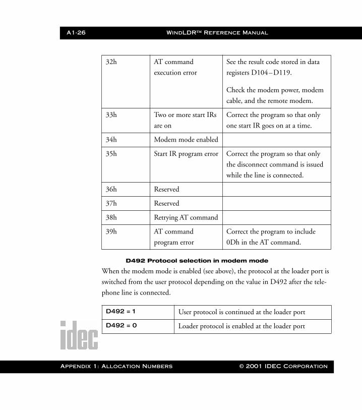
A1-26 WindLDR™ Reference Manual
Appendix 1
WLDR ReferenceBook Page 26 Thursday, April 5, 2001 3:36 PM
D492 Protocol selection in modem mode
When the modem mode is enabled (see above), the protocol at the loader port is
switched from the user protocol depending on the value in D492 after the tele-
phone line is connected.
32h AT command
execution error
See the result code stored in data
registers D104–D119.
Check the modem power, modem
cable, and the remote modem.
33h Two or more start IRs
are on
Correct the program so that only
one start IR goes on at a time.
34h Modem mode enabled
35h Start IR program error Correct the program so that only
the disconnect command is issued
while the line is connected.
36h Reserved
37h Reserved
38h Retrying AT command
39h AT command
program error
Correct the program to include
0Dh in the AT command.
D492 = 1 User protocol is continued at the loader port
D492 = 0 Loader protocol is enabled at the loader port
: Allocation Numbers © 2001 IDEC Corporation
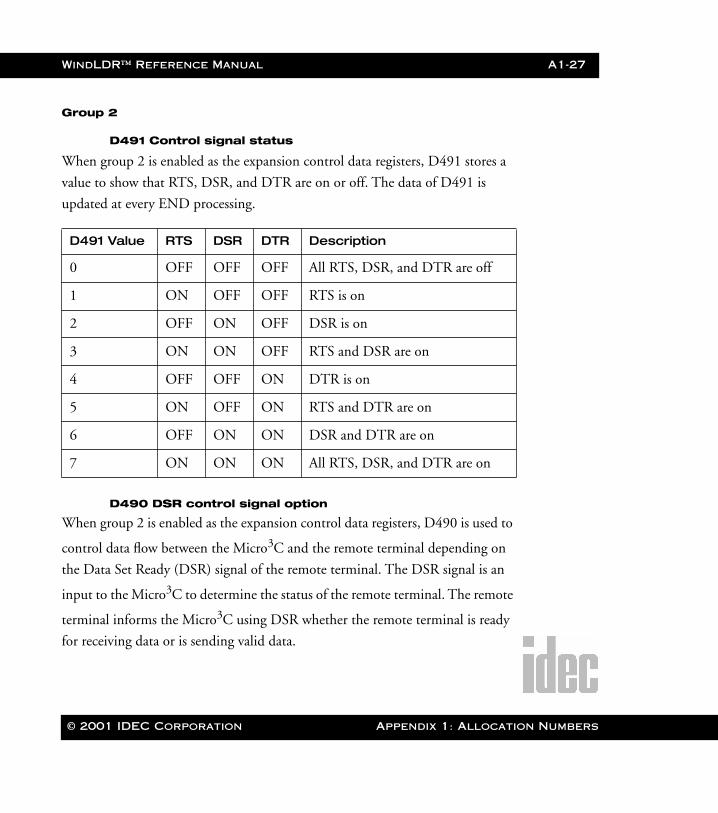
WindLDR™ Reference Manual A1-27
WLDR ReferenceBook Page 27 Thursday, April 5, 2001 3:36 PM
Group 2
D491 Control signal status
When group 2 is enabled as the expansion control data registers, D491 stores a
value to show that RTS, DSR, and DTR are on or off. The data of D491 is
updated at every END processing.
D490 DSR control signal option
When group 2 is enabled as the expansion control data registers, D490 is used to
control data flow between the Micro3C and the remote terminal depending on
the Data Set Ready (DSR) signal of the remote terminal. The DSR signal is an
input to the Micro3C to determine the status of the remote terminal. The remote
terminal informs the Micro3C using DSR whether the remote terminal is ready
for receiving data or is sending valid data.
D491 Value RTS DSR DTR Description
0 OFF OFF OFF All RTS, DSR, and DTR are off
1 ON OFF OFF RTS is on
2 OFF ON OFF DSR is on
3 ON ON OFF RTS and DSR are on
4 OFF OFF ON DTR is on
5 ON OFF ON RTS and DTR are on
6 OFF ON ON DSR and DTR are on
7 ON ON ON All RTS, DSR, and DTR are on
© 2001 IDEC Corporation Appendix 1: Allocation Numbers
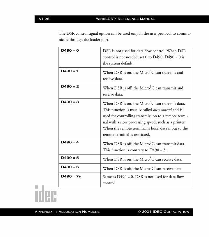
A1-28 WindLDR™ Reference Manual
Appendix 1
WLDR ReferenceBook Page 28 Thursday, April 5, 2001 3:36 PM
The DSR control signal option can be used only in the user protocol to commu-
nicate through the loader port.
D490 = 0 DSR is not used for data flow control. When DSR
control is not needed, set 0 to D490. D490 = 0 is
the system default.
D490 = 1 When DSR is on, the Micro3C can transmit and
receive data.
D490 = 2 When DSR is off, the Micro3C can transmit and
receive data.
D490 = 3 When DSR is on, the Micro3C can transmit data.
This function is usually called busy control and is
used for controlling transmission to a remote termi-
nal with a slow processing speed, such as a printer.
When the remote terminal is busy, data input to the
remote terminal is restricted.
D490 = 4 When DSR is off, the Micro3C can transmit data.
This function is contrary to D490 = 3.
D490 = 5 When DSR is on, the Micro3C can receive data.
D490 = 6 When DSR is off, the Micro3C can receive data.
D490 = 7+ Same as D490 = 0. DSR is not used for data flow
control.
: Allocation Numbers © 2001 IDEC Corporation

WindLDR™ Reference Manual A1-29
WLDR ReferenceBook Page 29 Thursday, April 5, 2001 3:36 PM
D489 DTR control signal option
When group 2 is the enabled as expansion control data registers, D489 is used to
control the Data Terminal Ready (DTR) signal to indicate the Micro3C operat-
ing status or transmitting/receiving status.
The DTR control signal option can be used only in the user protocol to commu-
nicate through the loader port.
D489 = 0 While the Micro3C is running, DTR is on whether
the Micro3 is transmitting or receiving data. While
the Micro3C is stopped, DTR remains off. Use this
option to indicate the Micro3C operating status.
D489 = 0 is the system default.
D489 = 1 While the Micro3C is transmitting data, DTR is
turned on. While the Micro3C is not transmitting
data, DTR remains off. Use this option when a
remote terminal operates in the half-duplex mode
since DTR goes on or off according to the transmit
data from the Micro3C.
D489 = 2 While the Micro3C is transmitting data, DTR
remains off. While the Micro3C is not transmitting
data, DTR is turned on. The DTR operation at this
option is contrary to the operation at D489 = 1.
D489 = 3 DTR remains off.
© 2001 IDEC Corporation Appendix 1: Allocation Numbers
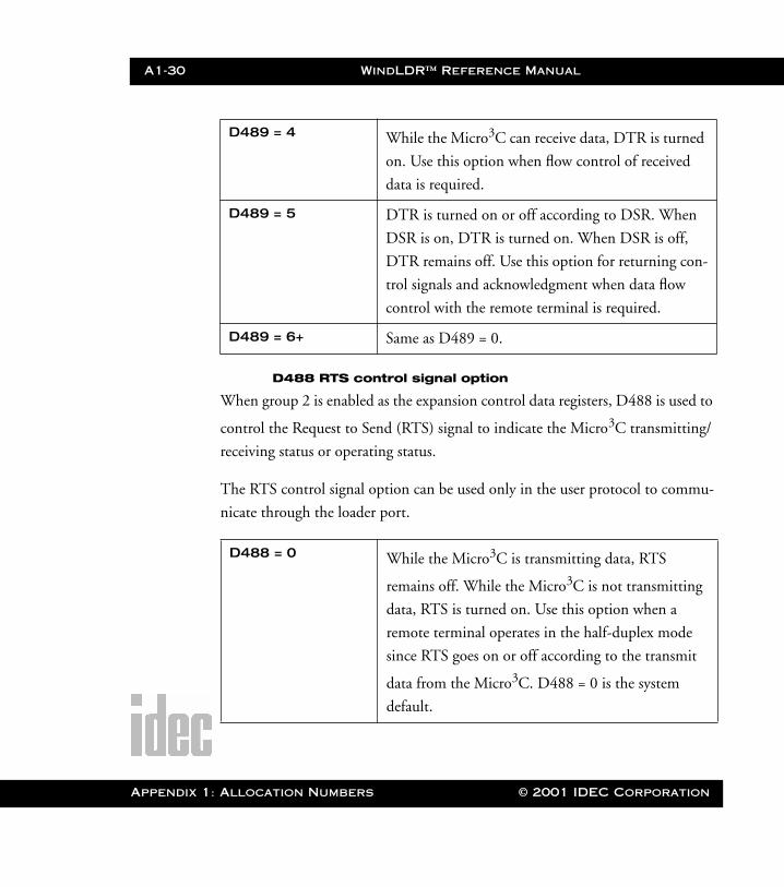
A1-30 WindLDR™ Reference Manual
Appendix 1
WLDR ReferenceBook Page 30 Thursday, April 5, 2001 3:36 PM
D488 RTS control signal option
When group 2 is enabled as the expansion control data registers, D488 is used to
control the Request to Send (RTS) signal to indicate the Micro3C transmitting/
receiving status or operating status.
The RTS control signal option can be used only in the user protocol to commu-
nicate through the loader port.
D489 = 4 While the Micro3C can receive data, DTR is turned
on. Use this option when flow control of received
data is required.
D489 = 5 DTR is turned on or off according to DSR. When
DSR is on, DTR is turned on. When DSR is off,
DTR remains off. Use this option for returning con-
trol signals and acknowledgment when data flow
control with the remote terminal is required.
D489 = 6+ Same as D489 = 0.
D488 = 0 While the Micro3C is transmitting data, RTS
remains off. While the Micro3C is not transmitting
data, RTS is turned on. Use this option when a
remote terminal operates in the half-duplex mode
since RTS goes on or off according to the transmit
data from the Micro3C. D488 = 0 is the system
default.
: Allocation Numbers © 2001 IDEC Corporation

WindLDR™ Reference Manual A1-31
WLDR ReferenceBook Page 31 Thursday, April 5, 2001 3:36 PM
D488 = 1 While the Micro3C is transmitting data, RTS is
turned on. While the Micro3C is not transmitting
data, RTS remains off. Use this option when a
remote terminal operates in the half-duplex mode
since RTS goes on or off according to the transmit
data from the Micro3C.
D488 = 2 While the Micro3C is running, RTS is on whether
the Micro3C is transmitting or receiving data. While
the Micro3C is stopped, RTS remains off. Use this
option to indicate the Micro3C operating status.
D488 = 3 RTS remains off.
D488 = 4 While the Micro3C can receive data, RTS is turned
on. Use this option when flow control of receive
data is required.
D488 = 5 RTS is turned on or off according to DSR. When
DSR is on, RTS is turned on. When DSR is off,
RTS remains off. Use this option for returning con-
trol signal and acknowledgment when data flow
control with the remote terminal is required.
D488 = 6+ Same as D488 = 0.
D487 Reserved
© 2001 IDEC Corporation Appendix 1: Allocation Numbers
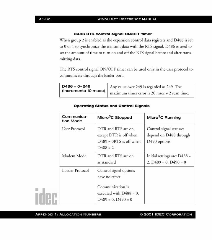
A1-32 WindLDR™ Reference Manual
Appendix 1
WLDR ReferenceBook Page 32 Thursday, April 5, 2001 3:36 PM
D486 RTS control signal ON/OFF timer
When group 2 is enabled as the expansion control data registers and D488 is set
to 0 or 1 to synchronize the transmit data with the RTS signal, D486 is used to
set the amount of time to turn on and off the RTS signal before and after trans-
mitting data.
The RTS control signal ON/OFF timer can be used only in the user protocol to
communicate through the loader port.
Operating Status and Control Signals
D486 = 0–249 (Increments 10 msec)
Any value over 249 is regarded as 249. The
maximum timer error is 20 msec + 2 scan time.
Communica-tion Mode
Micro3C Stopped Micro3C Running
User Protocol DTR and RTS are on,
except DTR is off when
D489 = 0RTS is off when
D488 = 2
Control signal statuses
depend on D488 through
D490 options
Modem Mode DTR and RTS are on
as standard
Initial settings are: D488 =
2, D489 = 0, D490 = 0
Loader Protocol Control signal options
have no effect
Communication is
executed with D488 = 0,
D489 = 0, D490 = 0
: Allocation Numbers © 2001 IDEC Corporation
© 2001 IDEC Corporation
WLDR ReferenceBook Page 1 Thursday, April 5, 2001 3:36 PM
Appendix 2: Error Codes
General Error CodesError data for the Micro-1 can be checked in the Online ➔ PLC Status dialog
box in WindLDR. PLC error codes for the Micro3 or Micro3C may be registered
on the PLC program loader or in the PLC Status dialog box in WindLDR.
When reading error data using FUN20, the error code is displayed using one,
two, or three digits in hexadecimal notation (0–F). These hexadecimal codes
consist of four items each in the first and second digits and two items in the third
digit. Each digit of the error code indicates a different set of conditions requiring
attention.
Each error code display indicates that the error marked with “X” has occurred.
Two or more marks indicate that multiple errors have occurred at the same time.
If any of the conditions from the First Digit Error Code chart on page A3 - 2 exist
(digit on the left), then this digit displays on the program loader. If conditions
from both the First Digit Error Code chart or the Second Digit Error Code chart
(on page A3 - 3) exist, then these two digits display.
For example, the error code may read out “21.” This indicates two conditions
requiring attention: “User program sum check error” from the Second Digit Error
Code chart and “Power failure” from the Third Digit Error Code chart. If the read-
out displays “D,” then this indicates three conditions exist from only the First
Digit Error Code chart.
Appendix 2: Error Codes

A2-2 WindLDR™ Reference Manual
Appendix 2
WLDR ReferenceBook Page 2 Thursday, April 5, 2001 3:36 PM
When control data register D92 is enabled using FUN10, the general error code
is stored in D92.
First Digit Error Codes
Error Code Display (Error Item)
User Program CRC Error
CRC Compari-son Code Keep Error
WDT Error Power Failure
0 (no error)
1 X
2 X
3 X X
4 X
5 X X
6 X X
7 X X X
8 X
9 X X
A X X
B X X X
C X X
D X X X
E X X X
F X X X X
: Error Codes © 2001 IDEC Corporation
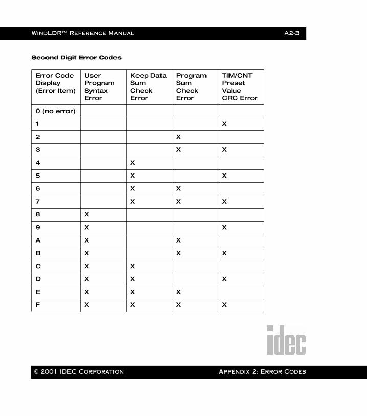
WindLDR™ Reference Manual A2-3
WLDR ReferenceBook Page 3 Thursday, April 5, 2001 3:36 PM
Second Digit Error Codes
Error Code Display (Error Item)
User Program Syntax Error
Keep Data Sum Check Error
Program Sum Check Error
TIM/CNT Preset Value CRC Error
0 (no error)
1 X
2 X
3 X X
4 X
5 X X
6 X X
7 X X X
8 X
9 X X
A X X
B X X X
C X X
D X X X
E X X X
F X X X X
© 2001 IDEC Corporation Appendix 2: Error Codes

A2-4 WindLDR™ Reference Manual
Appendix 2
WLDR ReferenceBook Page 4 Thursday, April 5, 2001 3:36 PM
Third Digit Error Codes
Micro-1 Error Causes and ActionsKeep Data Sum Check Error
If timer/counter data or internal relay on/off statuses stored in the base unit
RAM have changed during a power failure, this error is detected when power is
restored.
Power Failure
Power voltage is lower than the rated power voltage.
Timer/Counter Preset Value CRC Error
On starting operation, the CRC is executed on the timer/counter preset value
data stored in the base unit RAM to verify with the stored CRC comparison
codes. Discrepancies result in a CRC error.
User Program CRC Error
On starting operation, the CRC is executed on the user program to verify with
the stored CRC comparison codes. Discrepancy results in a CRC error. Transfer a
correct program to the PLC.
User Program Syntax Error
This error occurs when a syntax error is found in the user program.
Error Code Display (Error Item)
User Program Writing Error
System Program Error
0 (no error)
1 X
2 X
3 X X
: Error Codes © 2001 IDEC Corporation
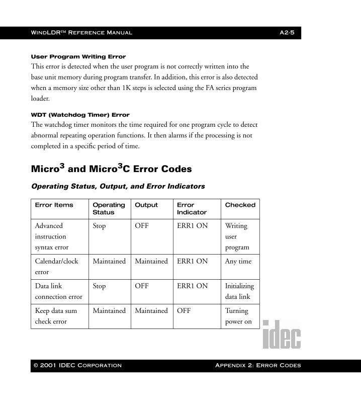
WindLDR™ Reference Manual A2-5
WLDR ReferenceBook Page 5 Thursday, April 5, 2001 3:36 PM
User Program Writing Error
This error is detected when the user program is not correctly written into the
base unit memory during program transfer. In addition, this error is also detected
when a memory size other than 1K steps is selected using the FA series program
loader.
WDT (Watchdog Timer) Error
The watchdog timer monitors the time required for one program cycle to detect
abnormal repeating operation functions. It then alarms if the processing is not
completed in a specific period of time.
Micro3 and Micro3C Error Codes
Operating Status, Output, and Error Indicators
Error Items Operating Status
Output Error Indicator
Checked
Advanced
instruction
syntax error
Stop OFF ERR1 ON Writing
user
program
Calendar/clock
error
Maintained Maintained ERR1 ON Any time
Data link
connection error
Stop OFF ERR1 ON Initializing
data link
Keep data sum
check error
Maintained Maintained OFF Turning
power on
© 2001 IDEC Corporation Appendix 2: Error Codes
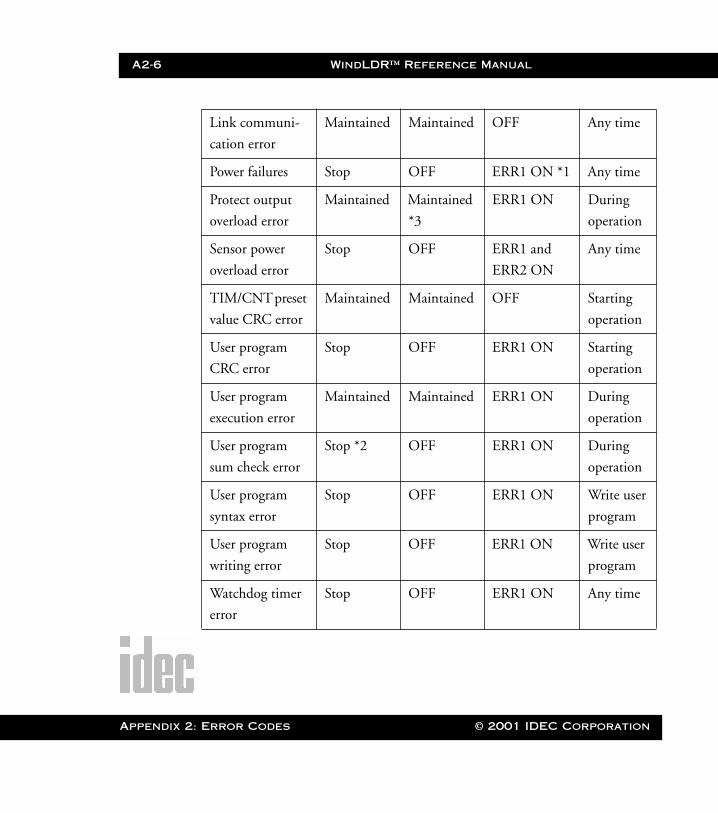
A2-6 WindLDR™ Reference Manual
Appendix 2
WLDR ReferenceBook Page 6 Thursday, April 5, 2001 3:36 PM
Link communi-
cation error
Maintained Maintained OFF Any time
Power failures Stop OFF ERR1 ON *1 Any time
Protect output
overload error
Maintained Maintained
*3
ERR1 ON During
operation
Sensor power
overload error
Stop OFF ERR1 and
ERR2 ON
Any time
TIM/CNT preset
value CRC error
Maintained Maintained OFF Starting
operation
User program
CRC error
Stop OFF ERR1 ON Starting
operation
User program
execution error
Maintained Maintained ERR1 ON During
operation
User program
sum check error
Stop *2 OFF ERR1 ON During
operation
User program
syntax error
Stop OFF ERR1 ON Write user
program
User program
writing error
Stop OFF ERR1 ON Write user
program
Watchdog timer
error
Stop OFF ERR1 ON Any time
: Error Codes © 2001 IDEC Corporation
WindLDR™ Reference Manual A2-7
WLDR ReferenceBook Page 7 Thursday, April 5, 2001 3:36 PM
NOTE: *1: When the power voltage to the Micro3 or Micro3C drops below the rated
value, the ERR1 indicator is lit. While the power voltage remains below
the rated value, the ERR1 indicator does not go on.
*2: When a program sum check error occurs, operation is stopped momen-
tarily to recompile the user program. After completing the recompilation,
operation resumes.
*3: Outputs where the error occurs are turned off.
Error Causes and Actions
1h: Power Failure (Power Off)
This error indicates when the power supply is lower than the specified voltage.
This error is also recorded when the power is turned off. Clear the error code
using FUN20 on the program loader.
2h: Watchdog Timer Error (Watchdog Time)
The watchdog timer monitors the time required for one program cycle (scan
time). When the time exceeds approximately 200 msec, the watchdog timer indi-
cates an error. If this error occurs frequently, the Micro3 or Micro3C should be
replaced. Clear the error code using FUN20 on the program loader
4h: Data Link Connection Error (PC Connect NG)
This error indicates that both data link slave stations (function selector switch set
to 1–6) and an expansion station (function selector switch set to 7) are con-
nected to the data link master station (function selector switch set to 0). Make
sure that the function selector switches at all slave stations are set to 1–6 in the
data link system. The expansion link function cannot be used in the data link
system.
© 2001 IDEC Corporation Appendix 2: Error Codes
A2-8 WindLDR™ Reference Manual
Appendix 2
WLDR ReferenceBook Page 8 Thursday, April 5, 2001 3:36 PM
To correct this error, change the function selector switch setting to 1–6 on slave
station units. Turn the power off and on again for the slave station unit. Then
turn the power off and on for the master station unit. Or, execute the link for-
matting sequence (FUN27) for the master station using the program loader.
8h: User Program CRC Error (Users Prg. CRC)
This error indicates that the user program stored in the Micro3 EEPROM is bro-
ken. Transfer a correct user program to the Micro3 or Micro3C, and clear the
error code using FUN20 on the program loader.
10h: Timer/Counter Preset Value CRC Error (TIM/CNT CRC)
This error indicates that the execution data of timer/counter preset values is bro-
ken. Clear the error code using FUN20 on the program loader, then the timer/
counter preset values are initialized to the values of the user program. Note that
modified preset values are cleared and the original values are restored when the
error code is cleared.
20h: User Program Sum Check Error (Prg. Sum Check)
This error indicates that the data of the user program compile area in the Micro3
or Micro3C RAM is broken. When this occurs, the user program is recompiled
automatically. Clear the error code using FUN20 on the program loader; then
the timer/counter preset values are initialized to the values of the user program.
Note that modified preset values are cleared and the original values are restored
when the error code is cleared.
: Error Codes © 2001 IDEC Corporation
WindLDR™ Reference Manual A2-9
WLDR ReferenceBook Page 9 Thursday, April 5, 2001 3:36 PM
40h: Keep Data Sum Check Error (Keep Data Sum)
This error indicates that the data designated to be maintained during power fail-
ure is broken because of memory backup failure. Clear the error code using
FUN20 on the program loader. Note that the keep data of internal relays and
shift registers is cleared when the error code is cleared.
80h: User Program Syntax Error (Syntax)
This error indicates that the user program has a syntax error or that FUN1
through FUN10 are set incorrectly. Correct the user program or FUN settings,
and transfer the corrected user program to Micro3. The error code is cleared
when a correct user program is transferred.
When this error occurs, the error message is displayed with a type code and an
address code of seven digits total.
100h: User Program Writing Error (EEPROM NG)
This error indicates a failure of writing into the Micro3 or Micro3C base unit
EEPROM when transferring a user program or when setting user program pro-
tection. The error code is cleared when writing into the EEPROM is completed
correctly. If this error occurs frequently, the Micro3 or Micro3C base unit should
be replaced.
200h: Protect Output Overload Error (Transistor NG)
This error is issued when a protect transistor output is overloaded during opera-
tion. In this case, only the overloaded output is forced off. When this error
occurs at the base station in the expansion link system, error indicator ERR1 is
lit at the base station. When the error is at the expansion station, error indicator
ERR1 is lit at both the base and expansion station.
© 2001 IDEC Corporation Appendix 2: Error Codes
A2-10 WindLDR™ Reference Manual
Appendix 2
WLDR ReferenceBook Page 10 Thursday, April 5, 2001 3:36 PM
If this error has occurred at output Q0 or Q20, then remove the cause of the
overload; the output will then restore normal operation automatically. Clear the
error code using FUN20 on the program loader.
400h: Sensor Power Overload Error (24V Overload)
This error indicates that the sensor power supply from the Micro3 is overloaded.
Both error indicators ERR1 and ERR2 will be lit.
When this error occurs at the base station in the expansion link system, error
indicators ERR1 and ERR2 are lit at the base station. When the error is at the
expansion station, ERR1 and ERR2 are lit at both the base and expansion sta-
tions.
To correct this error, reduce the sensor power output load within the rated value.
Then, either turn the power to the Micro3 off and on, or clear the error code
using FUN20 on the program loader.
800h: Calendar/Clock Error (Calendar NG)
This error indicates that the real time calendar/clock in the Micro3 base unit has
an error caused by invalid clock data due to a voltage drop or by erroneous quartz
oscillator operation.
Clear the error code using FUN20, and set the calendar/clock data using FUN28
on the program loader. Turn the power off and on again. If the error continues,
the Micro3 should be replaced.
: Error Codes © 2001 IDEC Corporation

WindLDR™ Reference Manual A2-11
WLDR ReferenceBook Page 11 Thursday, April 5, 2001 3:36 PM
Advanced Instruction Syntax Error (ADV Error)
NOTE: This option is applicable for the Micro3 only.
When a user program syntax error (error code 80h) is indicated with type code 5,
6, or 7 to signal an error related with advanced instruction, the detailed informa-
tion can be viewed from the error code indicated by the ADV error line.
Correct the error in the user program, and transfer the corrected user program to
Micro3. The error code is cleared when a correct user program is transferred.
Link Communication Error (COM Error)
This error indicates a communication error in the expansion link or data link
system. When this error occurs, special internal relay M305 (link communica-
tion error) is also turned on. The detailed information of this error can be viewed
from the error code indicated in the COM error line. This error code is stored in
control data register D94, if it is enabled using FUN10. When this error occurs,
program operation and all output statuses are maintained.
Error Code Error Details
1 The internal allocation number of the operand is invalid.
2 Input or special internal relay is designated as a destination.
3 Quantity of repeat cycles is set to 32 (or shift bits to 16 for
shift/rotate instructions) or more.
4 Advanced instruction which is not allowed for repeat usage is
programmed more than once.
© 2001 IDEC Corporation Appendix 2: Error Codes
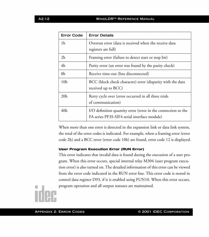
A2-12 WindLDR™ Reference Manual
Appendix 2
WLDR ReferenceBook Page 12 Thursday, April 5, 2001 3:36 PM
When more than one error is detected in the expansion link or data link system,
the total of the error codes is indicated. For example, when a framing error (error
code 2h) and a BCC error (error code 10h) are found, error code 12 is displayed.
User Program Execution Error (RUN Error)
This error indicates that invalid data is found during the execution of a user pro-
gram. When this error occurs, special internal relay M304 (user program execu-
tion error) is also turned on. The detailed information of this error can be viewed
from the error code indicated in the RUN error line. This error code is stored in
control data register D93, if it is enabled using FUN10. When this error occurs,
program operation and all output statuses are maintained.
Error Code Error Details
1h Overrun error (data is received when the receive data
registers are full)
2h Framing error (failure to detect start or stop bit)
4h Parity error (an error was found by the parity check)
8h Receive time-out (line disconnected)
10h BCC (block check character) error (disparity with the data
received up to BCC)
20h Retry cycle over (error occurred in all three trials
of communication)
40h I/O definition quantity error (error in the connection to the
FA series PF3S-SIF4 serial interface module)
: Error Codes © 2001 IDEC Corporation
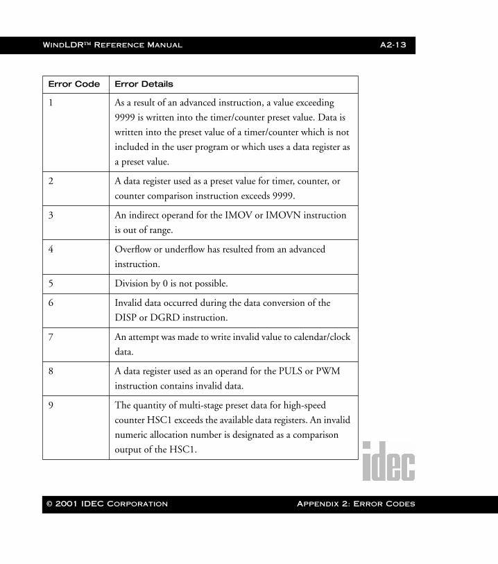
WindLDR™ Reference Manual A2-13
WLDR ReferenceBook Page 13 Thursday, April 5, 2001 3:36 PM
Error Code Error Details
1 As a result of an advanced instruction, a value exceeding
9999 is written into the timer/counter preset value. Data is
written into the preset value of a timer/counter which is not
included in the user program or which uses a data register as
a preset value.
2 A data register used as a preset value for timer, counter, or
counter comparison instruction exceeds 9999.
3 An indirect operand for the IMOV or IMOVN instruction
is out of range.
4 Overflow or underflow has resulted from an advanced
instruction.
5 Division by 0 is not possible.
6 Invalid data occurred during the data conversion of the
DISP or DGRD instruction.
7 An attempt was made to write invalid value to calendar/clock
data.
8 A data register used as an operand for the PULS or PWM
instruction contains invalid data.
9 The quantity of multi-stage preset data for high-speed
counter HSC1 exceeds the available data registers. An invalid
numeric allocation number is designated as a comparison
output of the HSC1.
© 2001 IDEC Corporation Appendix 2: Error Codes

A2-14 WindLDR™ Reference Manual
Appendix 2
WLDR ReferenceBook Page 14 Thursday, April 5, 2001 3:36 PM
Remove the cause of the error, and clear the error code using FUN20 on the pro-
gram loader. Special internal relay M304 is reset when restarting the Micro3 or
Micro3C operation or can also be reset using the program loader (MON, M304,
RST, [ENTER]).
Master Error Lists for All PLCs
Ladder to Mnemonic Error List
These errors codes occur during the compilation of a ladder file.
Error #000 Vertical line not properly connected at the top
A line must be connected to either another line, a coil, or a
power rail.
Error #001 Vertical line not properly connected at the bottom
A line must be connected to either another line, a coil, or a
power rail.
Error #002 …not properly connected on the left
An instruction or line must be connected to either another
line, a coil, or a power rail.
Error #003 …not properly connected on the right
An instruction or line must be connected to either another
line, a coil, or a power rail.
: Error Codes © 2001 IDEC Corporation
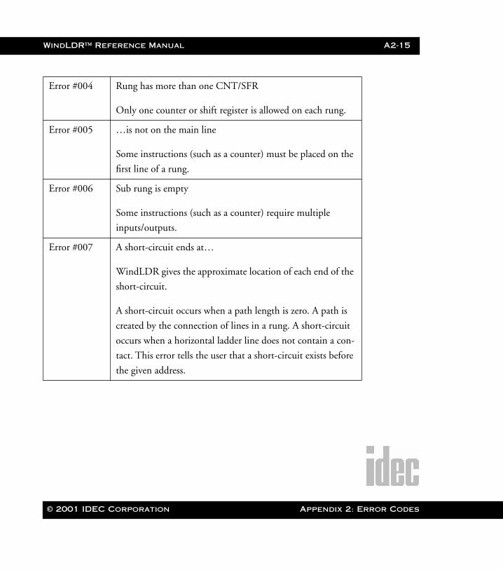
WindLDR™ Reference Manual A2-15
WLDR ReferenceBook Page 15 Thursday, April 5, 2001 3:36 PM
Error #004 Rung has more than one CNT/SFR
Only one counter or shift register is allowed on each rung.
Error #005 …is not on the main line
Some instructions (such as a counter) must be placed on the
first line of a rung.
Error #006 Sub rung is empty
Some instructions (such as a counter) require multiple
inputs/outputs.
Error #007 A short-circuit ends at…
WindLDR gives the approximate location of each end of the
short-circuit.
A short-circuit occurs when a path length is zero. A path is
created by the connection of lines in a rung. A short-circuit
occurs when a horizontal ladder line does not contain a con-
tact. This error tells the user that a short-circuit exists before
the given address.
© 2001 IDEC Corporation Appendix 2: Error Codes
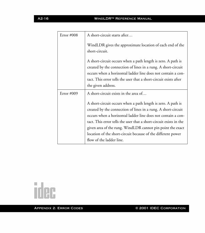
A2-16 WindLDR™ Reference Manual
Appendix 2
WLDR ReferenceBook Page 16 Thursday, April 5, 2001 3:36 PM
Error #008 A short-circuit starts after…
WindLDR gives the approximate location of each end of the
short-circuit.
A short-circuit occurs when a path length is zero. A path is
created by the connection of lines in a rung. A short-circuit
occurs when a horizontal ladder line does not contain a con-
tact. This error tells the user that a short-circuit exists after
the given address.
Error #009 A short-circuit exists in the area of…
A short-circuit occurs when a path length is zero. A path is
created by the connection of lines in a rung. A short-circuit
occurs when a horizontal ladder line does not contain a con-
tact. This error tells the user that a short-circuit exists in the
given area of the rung. WindLDR cannot pin point the exact
location of the short-circuit because of the different power
flow of the ladder line.
: Error Codes © 2001 IDEC Corporation
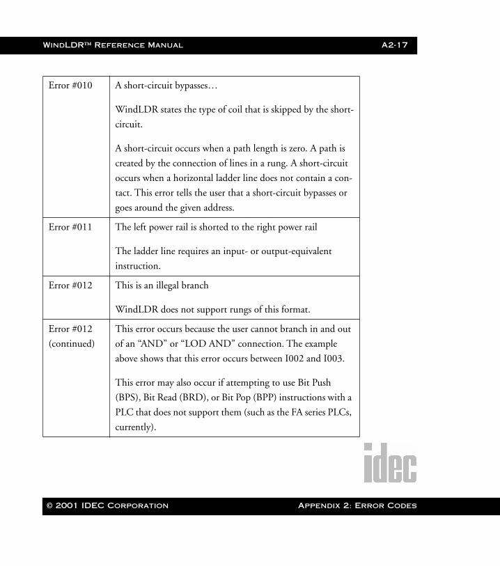
WindLDR™ Reference Manual A2-17
WLDR ReferenceBook Page 17 Thursday, April 5, 2001 3:36 PM
Error #010 A short-circuit bypasses…
WindLDR states the type of coil that is skipped by the short-
circuit.
A short-circuit occurs when a path length is zero. A path is
created by the connection of lines in a rung. A short-circuit
occurs when a horizontal ladder line does not contain a con-
tact. This error tells the user that a short-circuit bypasses or
goes around the given address.
Error #011 The left power rail is shorted to the right power rail
The ladder line requires an input- or output-equivalent
instruction.
Error #012 This is an illegal branch
WindLDR does not support rungs of this format.
Error #012
(continued)
This error occurs because the user cannot branch in and out
of an “AND” or “LOD AND” connection. The example
above shows that this error occurs between I002 and I003.
This error may also occur if attempting to use Bit Push
(BPS), Bit Read (BRD), or Bit Pop (BPP) instructions with a
PLC that does not support them (such as the FA series PLCs,
currently).
© 2001 IDEC Corporation Appendix 2: Error Codes
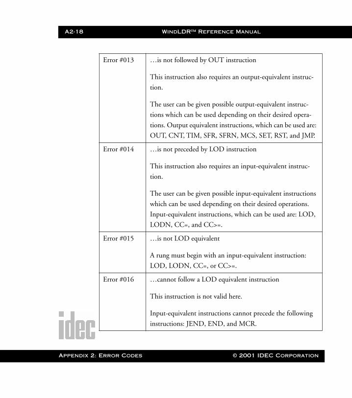
A2-18 WindLDR™ Reference Manual
Appendix 2
WLDR ReferenceBook Page 18 Thursday, April 5, 2001 3:36 PM
Error #013 …is not followed by OUT instruction
This instruction also requires an output-equivalent instruc-
tion.
The user can be given possible output-equivalent instruc-
tions which can be used depending on their desired opera-
tions. Output equivalent instructions, which can be used are:
OUT, CNT, TIM, SFR, SFRN, MCS, SET, RST, and JMP.
Error #014 …is not preceded by LOD instruction
This instruction also requires an input-equivalent instruc-
tion.
The user can be given possible input-equivalent instructions
which can be used depending on their desired operations.
Input-equivalent instructions, which can be used are: LOD,
LODN, CC=, and CC>=.
Error #015 …is not LOD equivalent
A rung must begin with an input-equivalent instruction:
LOD, LODN, CC=, or CC>=.
Error #016 …cannot follow a LOD equivalent instruction
This instruction is not valid here.
Input-equivalent instructions cannot precede the following
instructions: JEND, END, and MCR.
: Error Codes © 2001 IDEC Corporation
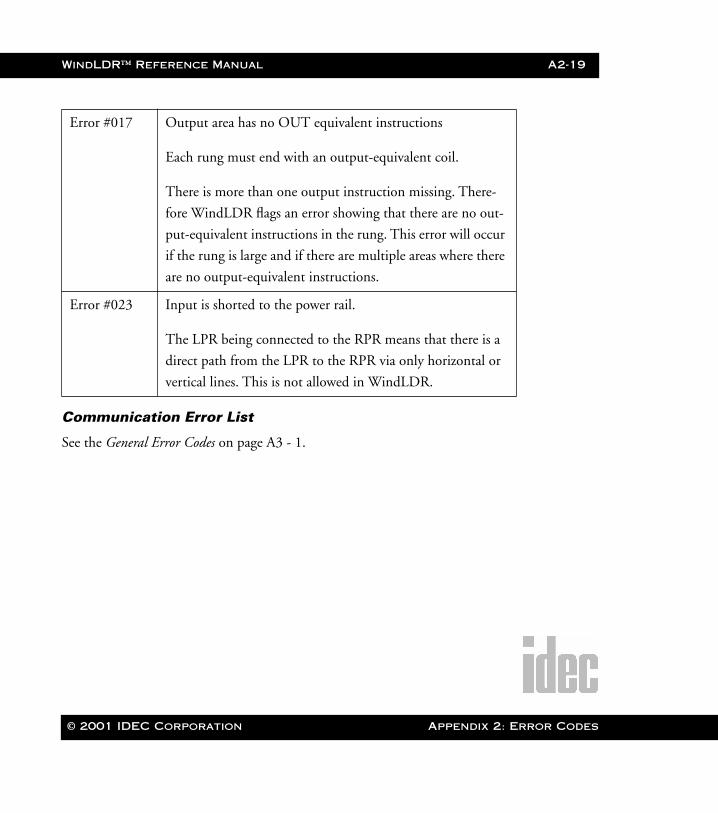
WindLDR™ Reference Manual A2-19
WLDR ReferenceBook Page 19 Thursday, April 5, 2001 3:36 PM
Communication Error List
See the General Error Codes on page A3 - 1.
Error #017 Output area has no OUT equivalent instructions
Each rung must end with an output-equivalent coil.
There is more than one output instruction missing. There-
fore WindLDR flags an error showing that there are no out-
put-equivalent instructions in the rung. This error will occur
if the rung is large and if there are multiple areas where there
are no output-equivalent instructions.
Error #023 Input is shorted to the power rail.
The LPR being connected to the RPR means that there is a
direct path from the LPR to the RPR via only horizontal or
vertical lines. This is not allowed in WindLDR.
© 2001 IDEC Corporation Appendix 2: Error Codes
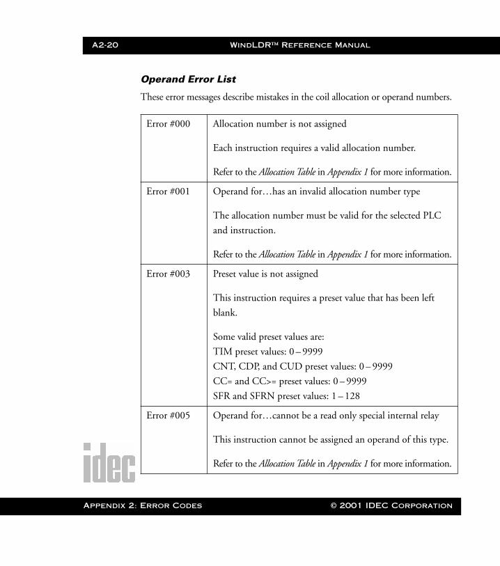
A2-20 WindLDR™ Reference Manual
Appendix 2
WLDR ReferenceBook Page 20 Thursday, April 5, 2001 3:36 PM
Operand Error List
These error messages describe mistakes in the coil allocation or operand numbers.
Error #000 Allocation number is not assigned
Each instruction requires a valid allocation number.
Refer to the Allocation Table in Appendix 1 for more information.
Error #001 Operand for…has an invalid allocation number type
The allocation number must be valid for the selected PLC
and instruction.
Refer to the Allocation Table in Appendix 1 for more information.
Error #003 Preset value is not assigned
This instruction requires a preset value that has been left
blank.
Some valid preset values are:
TIM preset values: 0 – 9999
CNT, CDP, and CUD preset values: 0 – 9999
CC= and CC>= preset values: 0 – 9999
SFR and SFRN preset values: 1 – 128
Error #005 Operand for…cannot be a read only special internal relay
This instruction cannot be assigned an operand of this type.
Refer to the Allocation Table in Appendix 1 for more information.
: Error Codes © 2001 IDEC Corporation
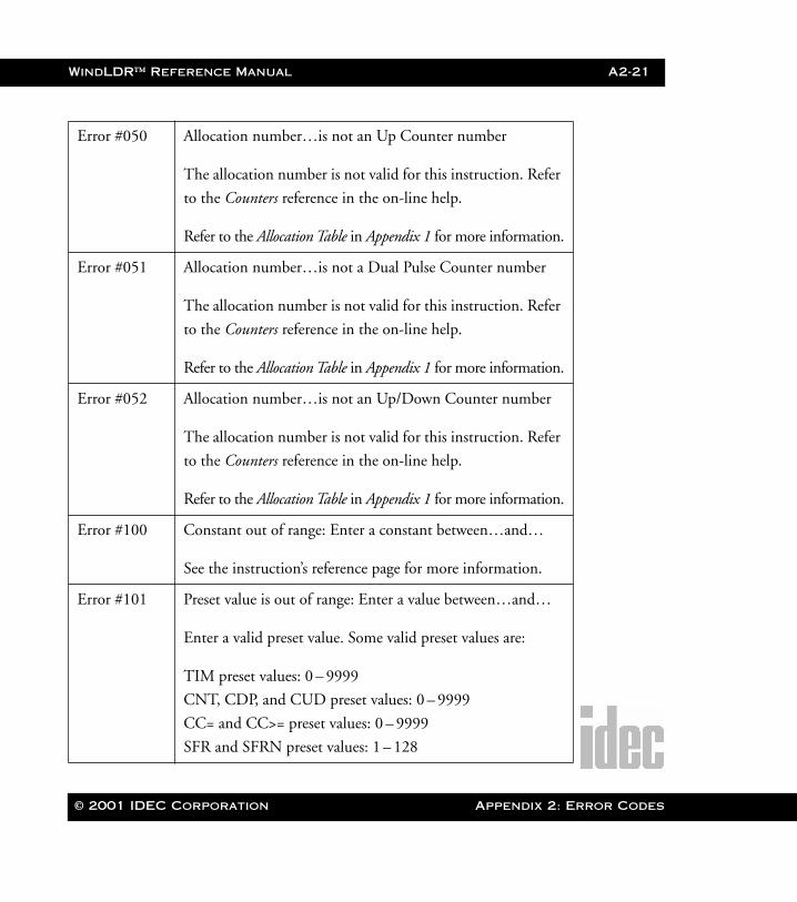
WindLDR™ Reference Manual A2-21
WLDR ReferenceBook Page 21 Thursday, April 5, 2001 3:36 PM
Error #050 Allocation number…is not an Up Counter number
The allocation number is not valid for this instruction. Refer
to the Counters reference in the on-line help.
Refer to the Allocation Table in Appendix 1 for more information.
Error #051 Allocation number…is not a Dual Pulse Counter number
The allocation number is not valid for this instruction. Refer
to the Counters reference in the on-line help.
Refer to the Allocation Table in Appendix 1 for more information.
Error #052 Allocation number…is not an Up/Down Counter number
The allocation number is not valid for this instruction. Refer
to the Counters reference in the on-line help.
Refer to the Allocation Table in Appendix 1 for more information.
Error #100 Constant out of range: Enter a constant between…and…
See the instruction’s reference page for more information.
Error #101 Preset value is out of range: Enter a value between…and…
Enter a valid preset value. Some valid preset values are:
TIM preset values: 0 – 9999
CNT, CDP, and CUD preset values: 0 – 9999
CC= and CC>= preset values: 0 – 9999
SFR and SFRN preset values: 1 – 128
© 2001 IDEC Corporation Appendix 2: Error Codes

A2-22 WindLDR™ Reference Manual
Appendix 2
WLDR ReferenceBook Page 22 Thursday, April 5, 2001 3:36 PM
Error #150 Repeats are used, but repeat field is empty
See the instruction’s reference page for more information.
This error code applies only to advanced instructions.
Error #200 Allocation number is not assigned
Error #201 Integer operand is not all integers.
Enter only numeric digits, no alpha characters.
Error #202 Integer operand is out of DWORD range
See the instruction’s reference page for more information.
Error #203 Symbolic structure is not correct
This error occurs when in an assigned field two or more let-
ters are used with numbers in a field.
See the instruction’s reference page for more information.
Error #204 Unknown allocation number type character “…”
Refer to the Allocation Table in Appendix 1 for more information.
Error #205 Allocation number must be octal
Refer to the Allocation Table in Appendix 1 for more information.
Error #206 Allocation number is not valid for this PLC
Refer to the Allocation Table in Appendix 1 for more information.
Error #207 …instruction is not valid for…
: Error Codes © 2001 IDEC CorporationThis instruction is not valid for this PLC. You must either
change it to a similar supported instruction or change the
PLC with which you are working with.
See the instruction’s reference page for more information.

© 2001 IDEC Corporation
WLDR ReferenceBook Page 1 Thursday, April 5, 2001 3:36 PM
Glossary
AAC Coupled Amplifier An amplifier in which only AC signals are ampli-
fied, and DC signals are totally ignored.
AC Input Module Device which converts various AC input signals
originating in the user’s switches to the appropriate
logic level required for use within the programma-
ble logic controller.
AC Output Module Device which converts the low-voltage logic levels
of the processor (CPU) to output signals for con-
trol of a user’s field device or load.
Access Time The time interval between the instant at which
information is: 1) Called for from storage and the
instant at which delivery is completed, i.e. The
read time; 2) Ready for storage and the instant at
which storage is completed, i.e. The write time.
Accumulator A register in the logical-arithmetic section of the
processor. It is commonly used for intermediate
storage of arithmetic results or other intermediate
operations.
Glossary
Glossary-2 WindLDR™ Reference Manual
Glossary
WLDR ReferenceBook Page 2 Thursday, April 5, 2001 3:36 PM
Address An identifying number which represents a location
in the processor’s memory. This number can also
relate to the location of an I/0.
Algorithm A prescribed set of rules for the solution of a prob-
lem in a definite number of steps, i.e. An algorithm
for PID.
Alphanumeric Used to identify a character set or data which con-
sists of both letters and numbers.
Alternating Current (AC) An electric current in which the charge-flow
reverses direction at recurring intervals.
Ambient Compensation The design of an instrument such that changes in
ambient temperature do not effect the readings of
the instrument.
Ambient Temperature The temperature within an encompassed atmo-
sphere.
Ampere (amp) A unit of electrical current. One (1) ampere is the
current which flows through one (1) ohm of resis-
tance at one (1) volt potential.
Analog Of or pertaining to the general class of devices in
which the output varies as a continuous function
of the input.
© 2001 IDEC Corporation
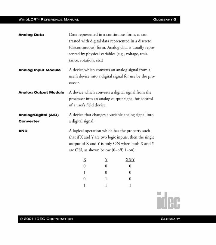
WindLDR™ Reference Manual Glossary-3
WLDR ReferenceBook Page 3 Thursday, April 5, 2001 3:36 PM
Analog Data Data represented in a continuous form, as con-
trasted with digital data represented in a discrete
(discontinuous) form. Analog data is usually repre-
sented by physical variables (e.g., voltage, resis-
tance, rotation, etc.)
Analog Input Module A device which converts an analog signal from a
user’s device into a digital signal for use by the pro-
cessor.
Analog Output Module A device which converts a digital signal from the
processor into an analog output signal for control
of a user’s field device.
Analog/Digital (A/D) A device that changes a variable analog signal into
Converter a digital signal.
AND A logical operation which has the property such
that if X and Y are two logic inputs, then the single
output of X and Y is only ON when both X and Y
are ON, as shown below (0=off, 1=on):
X Y X&Y
0 0 0
1 0 0
0 1 0
1 1 1
© 2001 IDEC Corporation Glossary
Glossary-4 WindLDR™ Reference Manual
Glossary
WLDR ReferenceBook Page 4 Thursday, April 5, 2001 3:36 PM
Annunciator A visual device consisting of a number of pilot
lights or buzzers. Each light or buzzer indicates the
condition which exists or existed in an associated
circuit.
ANSI Abbr.= American National Standards Associations.
Apparent Power Apparent power is the combination of reactive
power and active power.
Application Program A “PLC” or computer program that accomplishes
specific tacks.
Arithmetic Capability The ability to do arithmetic functions such as;
addition, subtraction, multiplication, and division
with the processor.
Armature The laminated iron core with wire wound around
it in which electromotive force a is produced by
magnetic induction in a motor or generator: usu-
ally a revolving part, but in AC machines (motors)
often stationary.
Array An arrangement of elements in one or more
dimensions.
ASA Abbr. = American Standard Association.
© 2001 IDEC Corporation
WindLDR™ Reference Manual Glossary-5
WLDR ReferenceBook Page 5 Thursday, April 5, 2001 3:36 PM
ASCII Abbr.= American Standards Code for Information
Interchanges. This is the code whereby E 8-bit
configurations are defined for all alpha-numeric
characters.
Assembly Language A computer language that has one-to-one corre-
spondence with an assembly program. The assem-
bly program directs a computer to operate on a
program in symbolic language (i.e. FORTRAN) to
produce a program in machine language.
Asynchronous Shift A shift register which is loaded and shifted only at
Register data entry, no clock is required.
Asynchronous A mode of data transmission where each character
Transmission is preceded by a start bit and is terminated with a
stop bit.
Automatic Reset To automatically return a device to the “0” or off
state after a given period of time, or condition.
Auxiliary Contacts In a switching device, contacts, in addition to the
main circuit contacts, which function with the
movement of the latter.
BBandwidth The frequency range in which the magnitude of
the system gain expressed in db is within the 3 db
band.
© 2001 IDEC Corporation Glossary

Glossary-6 WindLDR™ Reference Manual
Glossary
WLDR ReferenceBook Page 6 Thursday, April 5, 2001 3:36 PM
Baud A unit of data transmission, typically bits per sec-
ond.
Baud Rate Synonymous with signal events (bits) per second
and used as a measure of serial data flow between a
computer and/or communication
BCD (Binary Coded A notation system that represents each decimal as a
Decimal) four (4) bit binary code of “1” or “0”.
BCD DEC
0000 0
0001 1
0010 2
0011 3
0100 4
0101 5
0110 6
0111 7
1000 8
1001 9
Binary Number System A base 2 numbering system in which numbers are
represented by “1’s” and “0’s”.
Binary Word A related grouping of “1’s” and “0’s”’ whose mean-
ing is determined by position, or whose numerical
value is designated by the binary system of num-
bers.
© 2001 IDEC Corporation
WindLDR™ Reference Manual Glossary-7
WLDR ReferenceBook Page 7 Thursday, April 5, 2001 3:36 PM
Bipolar Refers to transistors in which the working current
consists of both positive and negative electrical
charges and flows through two (2) types of
CARRY, A condition occurring during addition
when the sum of two digits in the same column
exceeds the base. The carry digit is added to the
next column.
Bit A contraction of binary digit, the smallest unit of
information in binary notation. A bit is a Zero (0)
or a One (1).
Bit Rate The rate at which binary digits, or pulses repre-
senting them, pass a given point of the communi-
cations line.
Block A variable or fixed group of bits or words handled
as a unit.
Block Diagram A simplified schematic representing major electri-
cal components.
Boolean Algebra A logical algebra system, named after its inventor
George Boole, that represents ON-OFF relation-
ships symbolically as implied by the operators. (i.e.
AND, OR, NOT)
Boolean Equation An expression of relationships between logic func-
tions.
© 2001 IDEC Corporation Glossary
Glossary-8 WindLDR™ Reference Manual
Glossary
WLDR ReferenceBook Page 8 Thursday, April 5, 2001 3:36 PM
Boot The process of loading a program into the com-
puter and bringing it up on the screen.
BPS Abbr. = Bits Per Second.
Bounce Filter The electronic circuitry used to eliminate the
effects of contact bounces within a mechanical
switching device.
Branch An instruction which then executed may cause the
arithmetic and control unit to obtain the next
instruction from some location other than the next
sequential location. (See JUMP). 2) A point in a
program where there may be alternative paths of
instructions.
Bridge Rectifier A full-wave rectifier that conducts current in only
one direction of the input signal (current). AC
voltage applied to the input results in the approxi-
mate DC voltage at the output.
BTU Abbr. = British Thermal Unit
Buffer A storage device for temporally holding of data.
Alternately, can also be defined as a circuit inserted
between circuits to perform an isolating function.
Bus A channel, wire, or line along which data can be
sent or received, e.g. Address bus or Data bus.
© 2001 IDEC Corporation
WindLDR™ Reference Manual Glossary-9
WLDR ReferenceBook Page 9 Thursday, April 5, 2001 3:36 PM
Byte A group of adjacent bits (usually eight [8]) oper-
ated on as a unit.
CCartridge Tapeloader- A magnetic tape recording and playback device for
Recorder entering or storing programs, data, or both.
Cascade A group of registers arranged in succession so that
each segment is derived from or acts on the preced-
ing register.
Central Processing Unit The component of the PLC, often referred to as
(CPU) the processor, that contains the primary memory,
performs math and logic operations, and executes
the user’s program.
Channel A path for electrical transmission of signals
between two or more points.
Character A symbol (such as; a letter or number) that repre-
sents information.
Checksum The sum of a group of data items associated with
the group for checking purposes.
Clear To return the contents in a storage (registers) unit
to zero.
Clock A pulse generator which synchronizes the timing
of various logic circuits and memory in the proces-
sor (CPU).
© 2001 IDEC Corporation Glossary

Glossary-10 WindLDR™ Reference Manual
Glossary
WLDR ReferenceBook Page 10 Thursday, April 5, 2001 3:36 PM
Coaxial Cable A cable consisting of an outer conductor concen-
tric to an inner conductor, separated from each
other by a dielectric material.
Code A system of symbols (bits) used to represent data
(characters).
Computer Interface A device designed for data communications
between a central computer and a programmable
logic controller (PLC).
Conditional Jump A jump instruction that is subject to the result of a
comparison made within the program.
Copy To read data from a source, leaving the source data
unchanged, and to write the same data else where
in a form that may differ from that of the source.
Core Memory A device used to store information in ferrous cores,
which may be magnetized in either polarity to rep-
resent a logical “1’s” or “0’s”. This type of data
memory is read/write and is nonvolatile.
Counter A location internal to the processor (CPU) which
can be set to an initial number and increased and/
or decreased.
CRT Terminal A cathode ray tube used to display various infor-
mation, ladder programs, data lists, and applica-
tion reports. (See data terminal)
© 2001 IDEC Corporation
WindLDR™ Reference Manual Glossary-11
WLDR ReferenceBook Page 11 Thursday, April 5, 2001 3:36 PM
Current Loop A method of transmitting data that utilizes the
presence and absence of current pulses.
Cursor A symbol on a CRT screen that indicates the next
position that a character will be written.
Cycle 1, One completion of a sequence of operations. 2,
The interval of time to terminate a sequence of
operation.
DDaisy Chain Term that represents the method of wiring the
same signal to several devices.
Data A general term for any type information processed
by a computer or a programmable logic controller.
Data Link Equipment, especially transmission cables and
interfaces, which complete the communications
connections and permitting the transmission of
data.
Data Processing A procedure for collecting data, acting on it, and
producing a specific result.
Data Set A device that converts the signals of a data terminal
to signals that are suitable for transmission over
communication lines. (See Modem).
© 2001 IDEC Corporation Glossary
Glossary-12 WindLDR™ Reference Manual
Glossary
WLDR ReferenceBook Page 12 Thursday, April 5, 2001 3:36 PM
Data Terminal A device where a programmable logic controller’s
or computer’s memory data can enter or leave the
system, (See CRT Terminal).
Debugging The identification and elimination of mistakes in
hardware (wiring equipment) and the software
(user’s program).
Decoder The circuitry used to interpret data and detect an
individual address.
Diagnostic Program A test program within the processor, or user mem-
ory used to help isolate hardware and/or software
malfunctions within the PLC.
Differential See RS-422.
Digital Data Data represented in discrete, discontinuous form,
as contrasted with continuous analog data. Digital
data is usually represented by means of coded char-
acters (e.g., numbers, signs, symbols, etc.)
Digital to Analog A device which transforms digital data into analog
Converter data.
Disabled A program interruption to a sequence line, pre-
venting normal operation of that sequence.
© 2001 IDEC Corporation
WindLDR™ Reference Manual Glossary-13
WLDR ReferenceBook Page 13 Thursday, April 5, 2001 3:36 PM
Discrete 1) Separate and complete. 2) Pertaining to data in
the form of distinct elements or physical quanti-
ties, having distinctly recognizable values. Digital =
ON or OFF. I/Os are often referred to as discrete I/
Os.
Disk Drive A memory system which uses a rotating magnetic
disk to store data or information.
Documentation An orderly collection for the purpose of authenti-
cating hardware and software information.
Double Precision Data requiring two words or registers to process
because of data requirements.
Dump The process of putting the contents of memory on
a magnetic tape or disk.
Duplex Two-way data transmission. Full-duplex allows
simultaneous data transmission in both directions.
Half-duplex allows data transmission in either
Direction, But Only One Direction At A Time.
Dynamic Display A CRT screen display which is continuously
updated.
© 2001 IDEC Corporation Glossary
Glossary-14 WindLDR™ Reference Manual
Glossary
WLDR ReferenceBook Page 14 Thursday, April 5, 2001 3:36 PM
EEEPROM Abbr.= Electrically Erasable and Programmable
Read Only Memory. A read/write non-volatile type
of memory which uses electrical charges to main-
tain the program and reprogram.
Edit To deliberately modify the user’s program in the
processor’s memory.
Element An individual component within a programmable
logic controller’s program.
Encode To convert data by the use of a code in such a man-
ner that re-conversion to the original form is possi-
ble.
EPROM Abbr.= Erasable Programmable Read Only Mem-
ory. A nonvolatile memory which requires approxi-
mately a 30 minute exposure to a ultra-violet light
in order to be reprogrammed.
Error 1) The difference in value between actual response
and the desired response in the performance of a
controlled machine, system, or process. 2) An indi-
cation of a problem with hard-ware or software
within the programmable logic controller.
Escape The process of returning to the previous mode of
operation.
© 2001 IDEC Corporation
WindLDR™ Reference Manual Glossary-15
WLDR ReferenceBook Page 15 Thursday, April 5, 2001 3:36 PM
Execution The performance of a specific operation as accom-
plished through processing programmed instruc-
tions.
Execution Time The total time required to complete the execution
of the specific operation.
FFailure The termination of the capability of a functional
unit to perform its required function. A failure is
the effect of a fault.
Fault An accidental condition that causes a functional
unit to fail or to perform in the required manner.
Fault Current The maximum electrical current, far in excess of
normal current, that will flow in a short-circuited
system prior to the actuating of any current-limit-
ing device.
Feedback The signal or data returned to the programmable
logic controller from a controlled machine or pro-
cess to indicate it’s response to the control signal.
File An organized collection of documents or data.
Filter A device used to suppress electrical noise.
Firmware A series of instructions for internal use by the pro-
cessor only.
© 2001 IDEC Corporation Glossary
Glossary-16 WindLDR™ Reference Manual
Glossary
WLDR ReferenceBook Page 16 Thursday, April 5, 2001 3:36 PM
Fixed Point A notation of numbers where all numeric quanti-
ties are expressed by a set of digits with the decimal
point implicitly located at some predetermined
position.
Floating Point A form of number representation where decimal
points are not fixed by the length of the number,
itself, but are implicit.
Flow Chart A graphic diagram used to represent the function
of a system or sequence of operations, using sym-
bols to represent the logical data flow.
Full-Duplex Simultaneous two-way data transmission through
a communications channel.
GGraphics Methods and techniques for converting data to
and from a graphic display.
Grey Code A binary code in which sequential numbers are
represented by binary expressions, each of which
differs from the preceding expression in one place
only.
HHalf-Duplex Two-way, but not simultaneous, transmission of
data through a communications channel.
© 2001 IDEC Corporation
WindLDR™ Reference Manual Glossary-17
WLDR ReferenceBook Page 17 Thursday, April 5, 2001 3:36 PM
Hard Copy A permanent, printed document such as a ladder
diagram program listing.
Hardware The mechanical, electrical, and electronic device’s
which compose a programmable logic controller
system and it’s application.
Head A device, usually a small electromagnet, on a stor-
age medium, such as magnetic tapes, that reads,
records, or erases information on to that medium.
Hexadecimal A number system of the base “16”, comprised of
the digits, “0”, “1”, “2”, “3”, “4”, “5”, “6”, “7”,
“8”, “9”, “A”, “B”,”C”, “D”, “E”, and “F”.
II/0 Abbr. = Input and Output.
I/0 Capability Typically references the maximum quantity of
inputs and outputs that a programmable logic con-
troller can accommodate.
I/0 Modules 1) Input cards (modules) convert the higher field
input voltages required for the field device to the
low-level input signal used by the processor. 2)
Output cards (modules) convert the low-level pro-
cessor control signals to a usable level for field
devices.
© 2001 IDEC Corporation Glossary

Glossary-18 WindLDR™ Reference Manual
Glossary
WLDR ReferenceBook Page 18 Thursday, April 5, 2001 3:36 PM
I/0 Frame A device that houses a quantity of I/0 modules,
referred to as the I/0 RACK.
I/0 Scan A procedure the processor follows to monitor
inputs and control the output devices.
Inhibited Pertaining to a state of processing unit in which
certain operations are not allowed to occur.
Initialize To set to a starting position.
Input The data supplied to a programmable logic con-
troller for processing.
Input Devices Devices such as limit switches, pressure switches,
operator push buttons, etc., that supply data to the
programmable logic controller. Other inputs
include analog devices and digital encoders.
Instruction A set of bits which will generate certain prescribed
operation to be performed by the programmable
logic controller.
Interface A device that allows communications between sys-
tems or ports of different systems.
Interlock To arrange the control of machines or devices so
their operation is interdependent in order to assure
their proper coordination.
Interrupt To temporarily disrupt the normal sequence of
events on command.
© 2001 IDEC Corporation
WindLDR™ Reference Manual Glossary-19
WLDR ReferenceBook Page 19 Thursday, April 5, 2001 3:36 PM
Isolated I/0 Refers to digital I/0, where the devices are on a dif-
ferent voltage sources, i.e. Each I/0 has a separate
return (ground) line.
Isolation The voltage difference between external devices
and the controller logic incorporated in the I/0
modules for rejection of electrical noise.
JJitter Undesirable vibration on a display image on a dis-
play surface.
Jump A command to go from one sequence of instruc-
tions to another.
Jumper A short length of wire used to close a break and
make a connection between terminals in a circuit.
LLadder Diagram An industry standard-for symbolically representing
control logic relay systems.
Language A formal system of symbols and rules to express
and communicate information (data) between
people and machines.
Least Significant Digit The digit in a numbering system which represents
the smallest value.
© 2001 IDEC Corporation Glossary
Glossary-20 WindLDR™ Reference Manual
Glossary
WLDR ReferenceBook Page 20 Thursday, April 5, 2001 3:36 PM
Left Justified 1) A field of numbers which have no zero’s (0’s) to
its left. 2) An element re-positioned to the upper-
left most location possible of the programming
matrix.
Line Printer A high-speed output device that prints an entire
line of characters as a unit.
Load 1) A device placed in a circuit to which power is
delivered. 2) The process of entering data into the
processor’s memory.
Location A storage position in memory uniquely specified
by an address.
Local I/0 1) Physically mounting the I/0 frame (rack) in
close proximity to the processor. 2) The term used
for the I/O modules mounted within the same I/0
frame (rack) as the processor.
Logic A means of solving complex problems through the
repeated use of simple functions which define basic
concepts. The three (3) basic logic functions are
“AND,” “OR,” and “NOT”.
Logic Level The voltage magnitude associated with signal
pulses representing ones (+5 vdc) and zeros (0 vdc).
Loop The repeated execution of series of instructions for
a fixed number of times.
© 2001 IDEC Corporation
WindLDR™ Reference Manual Glossary-21
WLDR ReferenceBook Page 21 Thursday, April 5, 2001 3:36 PM
MMagnetic Core A device used for storing a bit of information in a
programmable logic controller. (See core memory)
Magnetic Tape A ribbon of plastic coated tape for use in magnetic
recording, used to store information.
Matrix A logic network in the form of a array of inputs
leads and outputs leads with logic elements provid-
ing inter-connections.
Medium Scale Any integrated circuit which has, between 12 and
Integration 100 equivalent gates.
Memory A device in which data is stored and may be
retrieved.
Memory Module A modular card consisting of a memory circuit and
is capable of storing a finite number of words.
Micro-Processor The central processing unit implemented in rela-
tively few integrated circuits which contain, Arith-
metic, Logic, Register, and Memory functions.
Microsecond One millionth of a second; 1 x 10⁻⁶ or 0.000001
second.
Millisecond One thousandth of a second; 1 x 10⁻³ or 0.001
second. Also expressed as “1ms”.
Mode A method of operation, i.e. programming mode,
search mode, etc.
© 2001 IDEC Corporation Glossary
Glossary-22 WindLDR™ Reference Manual
Glossary
WLDR ReferenceBook Page 22 Thursday, April 5, 2001 3:36 PM
Modem Abbr. = MOdulator DEModulator. Used to
describe the device applied to convert terminal
information for communications over telephone
lines, or other communications medium.
Monitoring Control A central programmable logic controller used in an
application where the process is continually
checked so that the operator may be alerted to pos-
sible malfunctions.
Most Significant Digit The digit in a numbering system that represents
the greatest value.
Multiplexing The process of transmitting multiple signals from
different sources over a common cable or transmis-
sion line by causing.
NNatural Binary A number system to the base of two (2), in which
the ones (1) and zeros (0) have a weighted value in
accordance with their relative position in the
binary word.
NEMA Standards Property characteristics adopted as the standard by
the National Electrical Manufactures Association.
Noise An extraneous signal in a electrical circuit capable
of interfering with the desired signal.
© 2001 IDEC Corporation

WindLDR™ Reference Manual Glossary-23
WLDR ReferenceBook Page 23 Thursday, April 5, 2001 3:36 PM
Nonvolatile Memory A memory that retains it’s information when
power is lost or removed.
OOctal Numbering A base eight (8) numbering system where only the
System digits 0 through 7 are used.
Off-Line Describes equipment or devices which are not
involved in direct communications with the pro-
grammable logic controller.
Ohm’s Law Currents (I) in terms of electromotive force (E)
and resistance (R) given in the equation; I = E/R.
On-Line Describes equipment or devices which are involved
in direct communications with the programmable
logic controller.
On-Line Operation That time when the programmable logic controller
is scanning the inputs and updating the outputs
accordingly.
Opto-Isolator A logic device using light and a photo-detector as a
isolator.
OR A logic operation having the property that if A and
B are logic inputs, then the single output of A and
B will only be ON if at least one of the two is ON,
as shown below (0=off, 1=on):
© 2001 IDEC Corporation Glossary
Glossary-24 WindLDR™ Reference Manual
Glossary
WLDR ReferenceBook Page 24 Thursday, April 5, 2001 3:36 PM
A B A or B
0 0 0
0 1 1
1 0 1
1 1 1
Output Information transferred from the programmable
logic controller to a output device or to external
storage.
Output Devices Devices such a solenoids, motor starters, etc., that
receive their controlling signal from a programma-
ble logic controller.
Overflow In an arithmetic operation, the generation of a
quantity beyond the capacity of the storage register
of location, which is to receive the result.
PParallel Operation Type of information transfer where by all bits of a
word are handled simultaneously.
Parallel Output Simultaneous availability of two or more bits,
channels, or registers.
Parity Bit A binary digit appended to a array of bits to make
the sum of all the bits always odd or always even.
© 2001 IDEC Corporation
WindLDR™ Reference Manual Glossary-25
WLDR ReferenceBook Page 25 Thursday, April 5, 2001 3:36 PM
Parity Check A diagnostic check that tests whether the numbers
of ones (or zeros) in a array of binary digits is
ODD or EVEN. Typically performed on words in
memory to insure they have not been altered in
storage or transmission.
PC Abbr. = Programmable Controller and/or Personal
Computer.
Peripheral Equipment used to input or receive output data
from a system. Typically printers, color operator
interfaces (CRT’s), act.
Pilot Type Device An electromechanical switch or set of relay contact,
which energizes a control circuit which in turns
energizes a high current load.
PLC Abbr.= Programmable Logic Controller.
Port A communication channel between devices.
Precision The degree of discrimination with which a quan-
tity is stated, e.g., A three digit numeral discrimi-
nated among 1000 possibilities. Precision is
contrasted with accuracy.
Printed Circuit A board on which a predetermined pattern of
printed connections has been formed.
© 2001 IDEC Corporation Glossary
Glossary-26 WindLDR™ Reference Manual
Glossary
WLDR ReferenceBook Page 26 Thursday, April 5, 2001 3:36 PM
Processor A unit in the programmable logic controller which
scans all the inputs and outputs in a predetermined
order. The processor monitors the status of all the
I/Os in response to the user’s programed instruc-
tions, stored within the memory, and energizes or
de-energizes outputs as the result of logical com-
parisons made through these programed instruc-
tions.
Program A sequence of instructions to be executed by the
programmable logic controller, to control a
machine or process.
Programmable Logic A solid state control system which has a user pro-
Controller grammable memory for storage of instructions to
implement specific functions such as; I/0 control
logic, timing, counting, arithmetic, and data
manipulation. A PC or PLC consists of a Central
Processing Unit (CPU), I/0 interface modules,
memory, and a programing device. A PC (PLC)
was purposely designed as an industrial control
system.
PROM Abbr.= Programmable Read Only Memory. A digi-
tal storage device which can be written into once,
but continually read.
© 2001 IDEC Corporation
WindLDR™ Reference Manual Glossary-27
WLDR ReferenceBook Page 27 Thursday, April 5, 2001 3:36 PM
Protocol A standardized procedure for establishing a com-
munications link between two or more devices
based on such elements as word structure and
length.
Pulse A brief voltage or current surge of a measurable
duration.
RRAM A Random Access Memory in a addressable LSI
device, used to store information (data). This
memory is a “Read/Write” and is volatile.
Read To copy, usually from one from of storage to
another, particularly from external or secondary
storage to internal storage. To sense the presence of
information on a recording device or medium.
Real Time Pertaining to the performance of a computation
during the actual time that a related physical pro-
cess transpires, in order that the results of the com-
putation can be used in guiding the physical
process.
Register A memory device capable of containing one or
more computer bits or words.
Remote I/0 The capability of locating an I/0 frame (rack) long
distances from the processor’s rack.
© 2001 IDEC Corporation Glossary
Glossary-28 WindLDR™ Reference Manual
Glossary
WLDR ReferenceBook Page 28 Thursday, April 5, 2001 3:36 PM
Right Justified Term applied to a field of numbers which exists in
a memory cell, location, or register, possessing no
significant zeros (0) to it’s right.
ROM Abbr.= Read Only Memory, a nonvolatile digital
storage device specified for a single function. Data
is permanently loaded into a “ROM”” memory,
and is available whenever needed.
Routine A series of computer instructions which performs a
specific limited task every time it is called up.
Rung A grouping of PLC instructions (symbols) which
controls an output. This is represented as one sec-
tion of a ladder logic diagram.
RS-232-C An E.I.A. (Electronic Industries Association) stan-
dard, covering the electrical and mechanical
requirements for serial transmission between ter-
minal devices. Because a voltage signal is utilized
RS-232C signals are limited to short distances
(approximately 60 feet) due to the voltage drop of
the wires.
RS-422 An E.I.A. (Electronic Industries Association) stan-
dard, covering the electrical and mechanical
requirements for serial transmission between ter-
minal devices. RS-422 relies on the difference
between two potentials, allowing the sending and
receiving devices to have different electrical
© 2001 IDEC Corporation

WindLDR™ Reference Manual Glossary-29
WLDR ReferenceBook Page 29 Thursday, April 5, 2001 3:36 PM
grounds, thereby allowing for long (up to two (2)
miles) communication distances.
(Also, Differential)
SScan Time The time necessary to completely execute the
entire programmable logic controller’s pro-
grammed instructions one time.
Schematic A diagram of a circuit in which symbols illustrate
circuit components.
SCR Abbr.= Silicon Controlled Rectifier. A solid state
three (3) terminal device which employs a control
signal to switch a DC voltage load. Also known as
a THYRISTOR.
Serial Operation A type of information transfer within a program-
mable logic controller whereby the bits are handled
sequentially rather than simultaneously, as they are
in a parallel operation. Slower than parallel for the
equivalent clock rate. However, only one (1) chan-
nel or wire is required for serial operation.
Setpoint The required or ideal value of a controlled variable,
usually preset in the system’s controller by the
operator.
© 2001 IDEC Corporation Glossary
Glossary-30 WindLDR™ Reference Manual
Glossary
WLDR ReferenceBook Page 30 Thursday, April 5, 2001 3:36 PM
Shift To move information serially right or left in the
register(s) within the programmable logic control-
ler.
Shift Register A storage area for bits in which the information is
input by shifting bits or bit patterns in either direc-
tion. Representing some sequence of events, as
opposed to numerical values. Can be operated
either synchronously or asynchronously.
Sign The symbol or bit which distinguishes the positive
or the negative value of a given number.
Significant Digit A digit that contributed to the precision of a
numeral. The number of significant digits is
counted, beginning with the digit contributing the
most value, called the significant digit and ending
with the least significant digit.
Software The user program which controls the operation of
a PLC.
Solid State Devices Electronic components that control electron flow
through solid materials such as crystals, transistors,
diodes, and integrated circuits.
State The logic “0” (OFF) or “1” (ON) condition in the
PLC’s memory or at a circuit’s input or output
module.
© 2001 IDEC Corporation
WindLDR™ Reference Manual Glossary-31
WLDR ReferenceBook Page 31 Thursday, April 5, 2001 3:36 PM
Static Non-moving electrical charge, such as on the plates
of a capacitor.
Status The ON or OFF condition of the referenced
device.
Storage Synonymous with “MEMORY”.
Surge Suppressor A series “RC” network attached to an I/0 module
for the purpose of limiting the electrical noise gen-
erated by inductive loads connected via hard con-
tacts. Typically wired in parallel with the inductive
load.
Synchronous Shift A shift register which uses a clock for timing of a
Register system operation and where only one (1) state
change per clock pulse.
Synchronous Having a constant time interval between successive
Transmission bits, characters, or words.
TTable A collection of data, each item being uniquely
identified either by some label or by it’s relative
position.
Tape Reader A unit which is capable of sensing data punched
tape.
© 2001 IDEC Corporation Glossary

Glossary-32 WindLDR™ Reference Manual
Glossary
WLDR ReferenceBook Page 32 Thursday, April 5, 2001 3:36 PM
Teletype A registered trademark of a type of printer terminal
and tape reader, which was originally manufac-
tured by the “TELETYPE CORP.”
Terminal Any fitting attached to a circuit or device for the
convenience in making electrical connections.
Terminator A hardware load employed on the end of a trans-
mission line or cable, used to balance the imped-
ance.
Thumb-Wheel Switch A rotating switch used to input numerical (BCD)
information to the programmable logic controller.
Thyristor See SCR.
Timeshare A term applied to a computer which is servicing
the needs of numerous users simultaneously.
Transceiver A PLC component that allows communications to
remote I/0 racks. It converts the data from parallel
communications used in the local configuration to
serial communications.
Transducer A device used to convert physical parameters such
as temperature, pressure, and weight into electrical
signals.
Transfer Module A unit which supplies processor redundancy by
switching program control automatically from one
processor to another in the event of a failure of the
© 2001 IDEC Corporation
WindLDR™ Reference Manual Glossary-33
WLDR ReferenceBook Page 33 Thursday, April 5, 2001 3:36 PM
first (primary) processor. Provides automatic and
instantaneous backup for critical control or process
systems.
TTL Abbr.= Transistor Transistor Logic. A family of
integrated circuit logic employing multiple emitter
transistors for rapid switching, operating in the
range of 0 to 5 vdc.
UUV Prom Abbr.= Ultraviolet Programmable Read Only
Memory. A non-volatile memory which requires
approximately a 30 minute exposure to ultraviolet
light in order to be reprogrammed.
VVolatile Memory A memory that loses it’s information if the power is
removed.
WWord A set of bits comprising the smallest addressable
unit of information within the programmable logic
controller.
Word Length The number of bits in a word.
Write To enter data into a storage device.
© 2001 IDEC Corporation Glossary
Glossary-34 WindLDR™ Reference Manual
Glossary
WLDR ReferenceBook Page 34 Thursday, April 5, 2001 3:36 PM
ZZero Suppression The elimination of non-significant zeros in a num-
ber.
Zener Diode A solid state voltage regulator for semiconductor
devices.
© 2001 IDEC Corporation
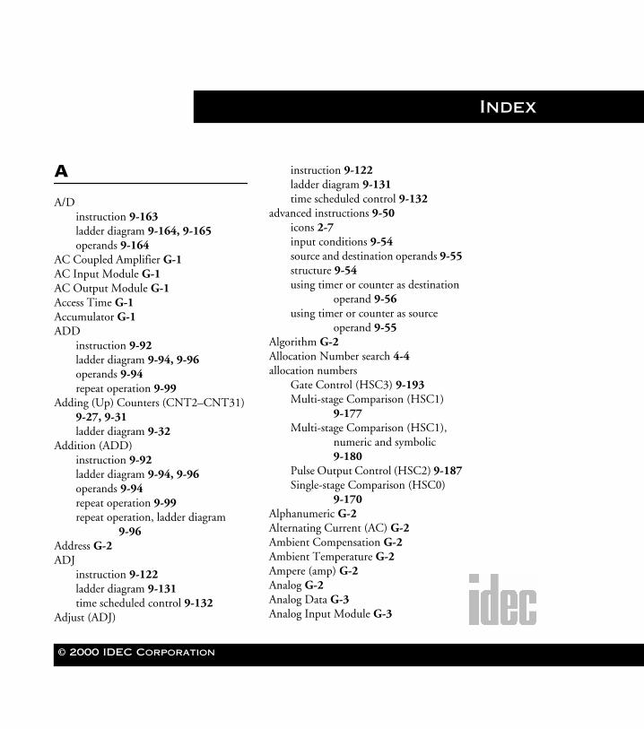
© 2000 IDEC Corporation
WLDR ReferenceBook Page I Thursday, April 5, 2001 3:36 PM
Index
A
A/Dinstruction 9-163ladder diagram 9-164, 9-165operands 9-164
AC Coupled Amplifier G-1AC Input Module G-1AC Output Module G-1Access Time G-1Accumulator G-1ADD
instruction 9-92ladder diagram 9-94, 9-96operands 9-94repeat operation 9-99
Adding (Up) Counters (CNT2–CNT31) 9-27, 9-31ladder diagram 9-32
Addition (ADD)instruction 9-92ladder diagram 9-94, 9-96operands 9-94repeat operation 9-99repeat operation, ladder diagram
9-96Address G-2ADJ
instruction 9-122ladder diagram 9-131time scheduled control 9-132
Adjust (ADJ)
instruction 9-122ladder diagram 9-131time scheduled control 9-132
advanced instructions 9-50icons 2-7input conditions 9-54source and destination operands 9-55structure 9-54using timer or counter as destination
operand 9-56using timer or counter as source
operand 9-55Algorithm G-2Allocation Number search 4-4allocation numbers
Gate Control (HSC3) 9-193Multi-stage Comparison (HSC1)
9-177Multi-stage Comparison (HSC1),
numeric and symbolic 9-180
Pulse Output Control (HSC2) 9-187Single-stage Comparison (HSC0)
9-170Alphanumeric G-2Alternating Current (AC) G-2Ambient Compensation G-2Ambient Temperature G-2Ampere (amp) G-2Analog G-2Analog Data G-3Analog Input Module G-3

Index II WindLDR™ Reference Manual
Index
WLDR ReferenceBook Page II Thursday, April 5, 2001 3:36 PM
Analog Output Module G-3analog potentiometer settings
Analog Read 0 (ANR0) 9-148Analog Read 0 (ANR0)
analog potentiometer settings 9-148instruction 9-146ladder diagram 9-147, 9-149operands 9-148
Analog To Digital Conversion (A/D)instruction 9-163ladder diagram 9-164, 9-165operands 9-164
Analog/Digital (A/D) Converter G-3AND 9-5, G-3And (AND) 9-5And Load (AND LOD) 9-5AND LOD 9-5
instruction 9-42And Not (ANDN) 9-5And Word (ANDW)
instruction 9-103ladder diagram 9-105operands 9-107repeat operation 9-108
ANDN 9-5ANDW
instruction 9-103ladder diagram 9-105operands 9-107repeat operation 9-108
Annunciator G-4ANR0
analog potentiometer settings 9-148instruction 9-146ladder diagram 9-147, 9-149operands 9-148
ANSI G-4Apparent Power G-4Append 4-4
Column instruction 9-207instruction 9-207Ladder Line instruction 9-207Rung instruction 9-207
Arithmetic Capability G-4Armature G-4Array G-4ASA G-4ASCII G-5Assembly Language G-5Asynchronous Shift Register G-5Asynchronous Transmission G-5Automatic Reset G-5Auxiliary Contacts G-5
B
Bandwidth G-5base unit system code (D90) 6-30basic instructions
icons 2-8sub-menu 9-4table 9-5
Batch Monitor dialog screen 1-3Batch Monitor option 8-20Baud G-6Baud Rate G-6BCC 10-15, 10-29
BCC digits (bytes) 10-17, 10-32calculation formula 10-31calculation start position 10-29comparing codes 10-32conversion type 10-31
© 2000 IDEC Corporation

WindLDR™ Reference Manual Index III
WLDR ReferenceBook Page III Thursday, April 5, 2001 3:36 PM
dialog box 10-6BCD (Binary Coded Decimal) G-6bi-directional shift register 9-38
ladder diagram 9-38Binary Arithmetic instructions 9-92Binary Number System G-6Binary Word G-6Bipolar G-7Bit G-7Bit Pop (BPP) 9-5Bit Push (BPS) 9-5Bit Read (BRD) 9-5Bit Shift and Rotate instruction 9-112Block G-7block check character (BCC) 10-15,
10-29BCC digits (bytes) 10-17, 10-32calculation formula 10-31calculation start position 10-29comparing codes 10-32conversion type 10-16, 10-31
Block Diagram G-7block diagram
Gate Control (HSC3) 9-195Pulse Output Control (HSC2) 9-190Single-Stage Comparison (HSC0)
9-172Boolean Algebra G-7Boolean Computation
instructions 9-103operands 9-107repeat operation ladder diagram
9-109Boolean Equation G-7Boot G-8borrow flags 9-95
Bounce Filter G-8BPP 9-5BPS 9-5, G-8Branch G-8BRD 9-5Bridge Rectifier G-8BTU G-8Buffer G-8Bus G-8Byte G-9
C
Calendar Read (CALR)instruction 9-122ladder diagram 9-124operands 9-126
Calendar Write (CALW)instruction 9-122ladder diagram 9-125, 9-127operands 9-126
CALRinstruction 9-122ladder diagram 9-124operands 9-126
CALWinstruction 9-122ladder diagram 9-125, 9-127operands 9-126
carry flags 9-95Cartridge Tapeloader-Recorder G-9Cascade G-9Catch Input
groups 6-24input number 6-24
CC= 9-6
© 2000 IDEC Corporation Index
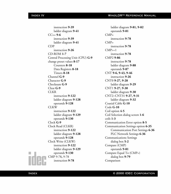
Index IV WindLDR™ Reference Manual
Index
WLDR ReferenceBook Page IV Thursday, April 5, 2001 3:36 PM
instruction 9-39ladder diagram 9-41
CC>= 9-6instruction 9-39ladder diagram 9-41
CDPinstruction 9-26
CD-ROM 1-7Central Processing Unit (CPU) G-9change preset values 8-17
Counters 8-18Data Registers 8-18Timers 8-18
Channel G-9Character G-9Checksum G-9Clear G-9CLKR
instruction 9-122ladder diagram 9-128operands 9-128
CLKWinstruction 9-122ladder diagram 9-129operands 9-130
Clock G-9Clock Read (CLKR)
instruction 9-122ladder diagram 9-128operands 9-128
Clock Write (CLKW)instruction 9-122ladder diagram 9-129operands 9-130
CMP 9-78, 9-78instruction 9-78
ladder diagram 9-81, 9-82operands 9-81
CMP=instruction 9-78
CMP>instruction 9-78
CMP>=1instruction 9-78
CMP2 9-86instruction 9-78ladder diagram 9-88operands 9-87
CNT 9-6, 9-43, 9-46instruction 9-26
CNT0 9-27, 9-28ladder diagram 9-29
CNT1 9-27, 9-30ladder diagram 9-30
CNT2–CNT31 9-27, 9-31ladder diagram 9-32
Coaxial Cable G-10Code G-10Coil option 4-5Coil Selection dialog screen 1-6coils 1-3Communication Error option 8-5Communication Settings option 6-35
Communication Port Settings 6-36PLC Network Settings 6-36
Communications Settingsdialog box 5-2
Compare (CMP)operands 9-81
Compare Equal To (CMP=)dialog box 9-79
Comparison
© 2000 IDEC Corporation
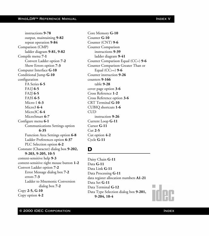
WindLDR™ Reference Manual Index V
WLDR ReferenceBook Page V Thursday, April 5, 2001 3:36 PM
instructions 9-78output, maintaining 9-82repeat operation 9-84
Comparison (CMP)ladder diagram 9-81, 9-82
Compile menu 7-1Convert Ladder option 7-2Show Errors option 7-3
Computer Interface G-10Conditional Jump G-10configuration
FA Series 6-5FA1J 6-5FA2J 6-5FA3S 6-5Micro-1 6-3Micro3 6-4Micro3C 6-4MicroSmart 6-7
Configure menu 6-1Communications Settings option
6-35Function Area Settings option 6-8Ladder Preferences option 6-37PLC Selection option 6-2
Constant (Character) dialog box 9-202, 9-203, 9-205, 10-5
context-sensitive help 9-3context-sensitive right mouse button 1-2Convert Ladder option 7-2
Error Message dialog box 7-2errors 7-3Ladder to Mnemonic Conversion
dialog box 7-2Copy 2-5, G-10Copy option 4-2
Core Memory G-10Counter G-10Counter (CNT) 9-6Counter Comparison
instructions 9-39ladder diagram 9-41
Counter Comparison Equal (CC=) 9-6Counter Comparison Greater Than or
Equal (CC>=) 9-6Counter instruction 9-26counters 9-166
table 9-28cover page option 3-6Cross Reference 1-2Cross Reference option 3-6CRT Terminal G-10CUBIQ shortcuts 1-6CUD
instruction 9-26Current Loop G-11Cursor G-11Cut 2-5Cut option 4-2Cycle G-11
D
Daisy Chain G-11Data G-11Data Link G-11Data Processing G-11data register allocation numbers A1-21Data Set G-11Data Terminal G-12Data Type Selection dialog box 9-201,
9-204, 10-4
© 2000 IDEC Corporation Index
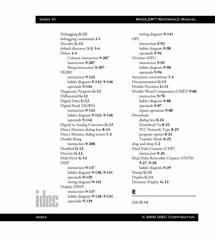
Index VI WindLDR™ Reference Manual
Index
WLDR ReferenceBook Page VI Thursday, April 5, 2001 3:36 PM
Debugging G-12debugging commands 2-1Decoder G-12default directory 3-3, 3-4Delete 4-4
Column instruction 9-207instruction 9-207Rung instruction 9-207
DGRDinstruction 9-142ladder diagram 9-143, 9-146operands 9-144
Diagnostic Program G-12Differential G-12Digital Data G-12Digital Read (DGRD)
instruction 9-142ladder diagram 9-143, 9-146operands 9-144
Digital to Analog Converter G-12Direct Monitor dialog box 8-14Direct Monitor dialog screen 1-3Disable Rung
instruction 9-208Disabled G-12Discrete G-13Disk Drive G-13DISP
instruction 9-137ladder diagram 9-138, 9-141operands 9-139wiring diagram 9-141
Display (DISP)instruction 9-137ladder diagram 9-138, 9-141operands 9-139
wiring diagram 9-141DIV
instruction 9-92ladder diagram 9-98operands 9-94
Division (DIV)instruction 9-92ladder diagram 9-98operands 9-94
document conventions 1-4Documentation G-13Double Precision G-13Double-Word Comparison (CMP2) 9-86
instruction 9-78ladder diagram 9-88operands 9-87repeat operation 9-88
Downloaddialog box 8-24Download To 8-25PLC Network Type 8-25program option 8-24Transfer Mode 8-25
drag and drop 1-2Dual Pulse Counter (CDP)
instruction 9-26Dual Pulse Reversible Counter (CNT0)
9-27, 9-28ladder diagram 9-29
Dump G-13Duplex G-13Dynamic Display G-13
E
Edit G-14
© 2000 IDEC Corporation
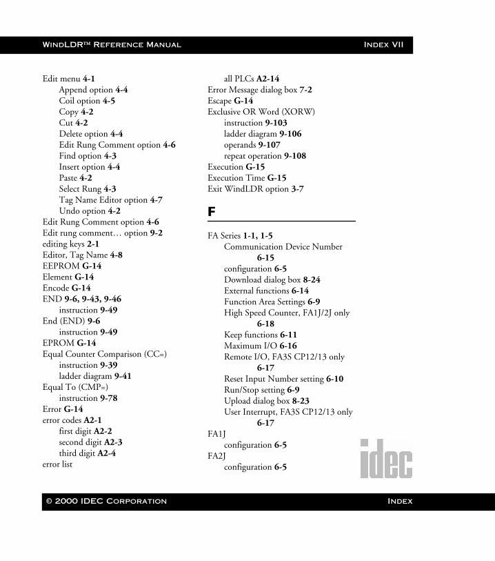
WindLDR™ Reference Manual Index VII
WLDR ReferenceBook Page VII Thursday, April 5, 2001 3:36 PM
Edit menu 4-1Append option 4-4Coil option 4-5Copy 4-2Cut 4-2Delete option 4-4Edit Rung Comment option 4-6Find option 4-3Insert option 4-4Paste 4-2Select Rung 4-3Tag Name Editor option 4-7Undo option 4-2
Edit Rung Comment option 4-6Edit rung comment… option 9-2editing keys 2-1Editor, Tag Name 4-8EEPROM G-14Element G-14Encode G-14END 9-6, 9-43, 9-46
instruction 9-49End (END) 9-6
instruction 9-49EPROM G-14Equal Counter Comparison (CC=)
instruction 9-39ladder diagram 9-41
Equal To (CMP=)instruction 9-78
Error G-14error codes A2-1
first digit A2-2second digit A2-3third digit A2-4
error list
all PLCs A2-14Error Message dialog box 7-2Escape G-14Exclusive OR Word (XORW)
instruction 9-103ladder diagram 9-106operands 9-107repeat operation 9-108
Execution G-15Execution Time G-15Exit WindLDR option 3-7
F
FA Series 1-1, 1-5Communication Device Number
6-15configuration 6-5Download dialog box 8-24External functions 6-14Function Area Settings 6-9High Speed Counter, FA1J/2J only
6-18Keep functions 6-11Maximum I/O 6-16Remote I/O, FA3S CP12/13 only
6-17Reset Input Number setting 6-10Run/Stop setting 6-9Upload dialog box 8-23User Interrupt, FA3S CP12/13 only
6-17FA1J
configuration 6-5FA2J
configuration 6-5
© 2000 IDEC Corporation Index
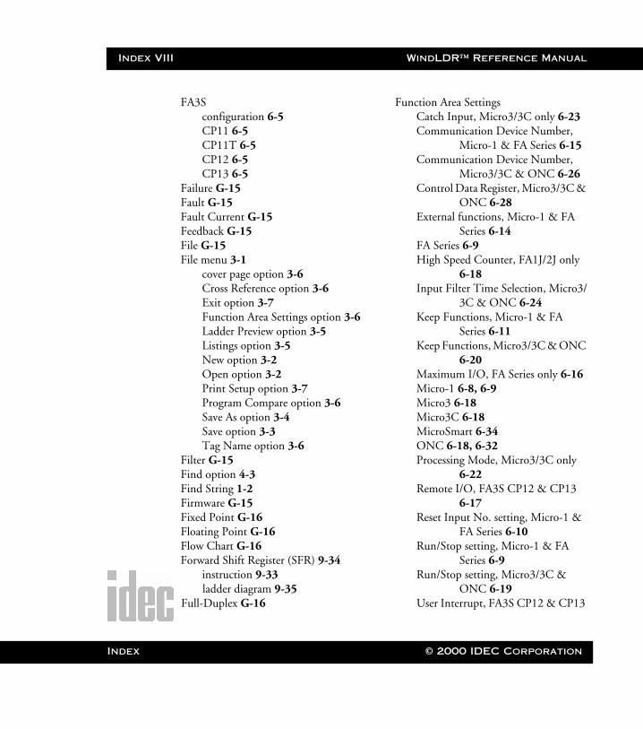
Index VIII WindLDR™ Reference Manual
Index
WLDR ReferenceBook Page VIII Thursday, April 5, 2001 3:36 PM
FA3Sconfiguration 6-5CP11 6-5CP11T 6-5CP12 6-5CP13 6-5
Failure G-15Fault G-15Fault Current G-15Feedback G-15File G-15File menu 3-1
cover page option 3-6Cross Reference option 3-6Exit option 3-7Function Area Settings option 3-6Ladder Preview option 3-5Listings option 3-5New option 3-2Open option 3-2Print Setup option 3-7Program Compare option 3-6Save As option 3-4Save option 3-3Tag Name option 3-6
Filter G-15Find option 4-3Find String 1-2Firmware G-15Fixed Point G-16Floating Point G-16Flow Chart G-16Forward Shift Register (SFR) 9-34
instruction 9-33ladder diagram 9-35
Full-Duplex G-16
Function Area SettingsCatch Input, Micro3/3C only 6-23Communication Device Number,
Micro-1 & FA Series 6-15Communication Device Number,
Micro3/3C & ONC 6-26Control Data Register, Micro3/3C &
ONC 6-28External functions, Micro-1 & FA
Series 6-14FA Series 6-9High Speed Counter, FA1J/2J only
6-18Input Filter Time Selection, Micro3/
3C & ONC 6-24Keep Functions, Micro-1 & FA
Series 6-11Keep Functions, Micro3/3C & ONC
6-20Maximum I/O, FA Series only 6-16Micro-1 6-8, 6-9Micro3 6-18Micro3C 6-18MicroSmart 6-34ONC 6-18, 6-32Processing Mode, Micro3/3C only
6-22Remote I/O, FA3S CP12 & CP13
6-17Reset Input No. setting, Micro-1 &
FA Series 6-10Run/Stop setting, Micro-1 & FA
Series 6-9Run/Stop setting, Micro3/3C &
ONC 6-19User Interrupt, FA3S CP12 & CP13
© 2000 IDEC Corporation
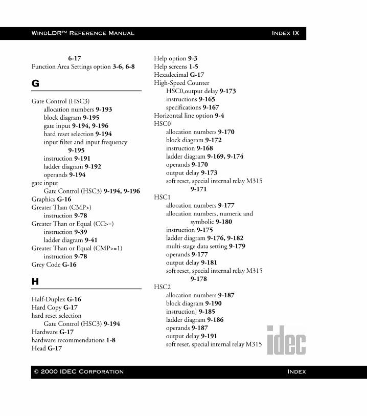
WindLDR™ Reference Manual Index IX
WLDR ReferenceBook Page IX Thursday, April 5, 2001 3:36 PM
6-17Function Area Settings option 3-6, 6-8
G
Gate Control (HSC3)allocation numbers 9-193block diagram 9-195gate input 9-194, 9-196hard reset selection 9-194input filter and input frequency
9-195instruction 9-191ladder diagram 9-192operands 9-194
gate inputGate Control (HSC3) 9-194, 9-196
Graphics G-16Greater Than (CMP>)
instruction 9-78Greater Than or Equal (CC>=)
instruction 9-39ladder diagram 9-41
Greater Than or Equal (CMP>=1)instruction 9-78
Grey Code G-16
H
Half-Duplex G-16Hard Copy G-17hard reset selection
Gate Control (HSC3) 9-194Hardware G-17hardware recommendations 1-8Head G-17
Help option 9-3Help screens 1-5Hexadecimal G-17High-Speed Counter
HSC0,output delay 9-173instructions 9-165specifications 9-167
Horizontal line option 9-4HSC0
allocation numbers 9-170block diagram 9-172instruction 9-168ladder diagram 9-169, 9-174operands 9-170output delay 9-173soft reset, special internal relay M315
9-171HSC1
allocation numbers 9-177allocation numbers, numeric and
symbolic 9-180instruction 9-175ladder diagram 9-176, 9-182multi-stage data setting 9-179operands 9-177output delay 9-181soft reset, special internal relay M315
9-178HSC2
allocation numbers 9-187block diagram 9-190instruction] 9-185ladder diagram 9-186operands 9-187output delay 9-191soft reset, special internal relay M315
© 2000 IDEC Corporation Index
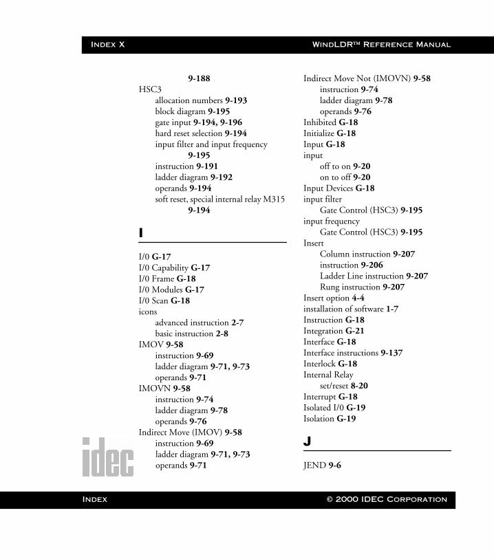
Index X WindLDR™ Reference Manual
Index
WLDR ReferenceBook Page X Thursday, April 5, 2001 3:36 PM
9-188HSC3
allocation numbers 9-193block diagram 9-195gate input 9-194, 9-196hard reset selection 9-194input filter and input frequency
9-195instruction 9-191ladder diagram 9-192operands 9-194soft reset, special internal relay M315
9-194
I
I/0 G-17I/0 Capability G-17I/0 Frame G-18I/0 Modules G-17I/0 Scan G-18icons
advanced instruction 2-7basic instruction 2-8
IMOV 9-58instruction 9-69ladder diagram 9-71, 9-73operands 9-71
IMOVN 9-58instruction 9-74ladder diagram 9-78operands 9-76
Indirect Move (IMOV) 9-58instruction 9-69ladder diagram 9-71, 9-73operands 9-71
Indirect Move Not (IMOVN) 9-58instruction 9-74ladder diagram 9-78operands 9-76
Inhibited G-18Initialize G-18Input G-18input
off to on 9-20on to off 9-20
Input Devices G-18input filter
Gate Control (HSC3) 9-195input frequency
Gate Control (HSC3) 9-195Insert
Column instruction 9-207instruction 9-206Ladder Line instruction 9-207Rung instruction 9-207
Insert option 4-4installation of software 1-7Instruction G-18Integration G-21Interface G-18Interface instructions 9-137Interlock G-18Internal Relay
set/reset 8-20Interrupt G-18Isolated I/0 G-19Isolation G-19
J
JEND 9-6
© 2000 IDEC Corporation
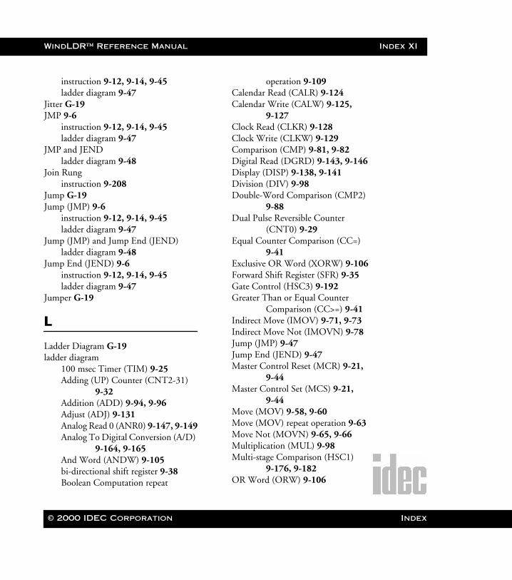
WindLDR™ Reference Manual Index XI
WLDR ReferenceBook Page XI Thursday, April 5, 2001 3:36 PM
instruction 9-12, 9-14, 9-45ladder diagram 9-47
Jitter G-19JMP 9-6
instruction 9-12, 9-14, 9-45ladder diagram 9-47
JMP and JENDladder diagram 9-48
Join Runginstruction 9-208
Jump G-19Jump (JMP) 9-6
instruction 9-12, 9-14, 9-45ladder diagram 9-47
Jump (JMP) and Jump End (JEND)ladder diagram 9-48
Jump End (JEND) 9-6instruction 9-12, 9-14, 9-45ladder diagram 9-47
Jumper G-19
L
Ladder Diagram G-19ladder diagram
100 msec Timer (TIM) 9-25Adding (UP) Counter (CNT2-31)
9-32Addition (ADD) 9-94, 9-96Adjust (ADJ) 9-131Analog Read 0 (ANR0) 9-147, 9-149Analog To Digital Conversion (A/D)
9-164, 9-165And Word (ANDW) 9-105bi-directional shift register 9-38Boolean Computation repeat
operation 9-109Calendar Read (CALR) 9-124Calendar Write (CALW) 9-125,
9-127Clock Read (CLKR) 9-128Clock Write (CLKW) 9-129Comparison (CMP) 9-81, 9-82Digital Read (DGRD) 9-143, 9-146Display (DISP) 9-138, 9-141Division (DIV) 9-98Double-Word Comparison (CMP2)
9-88Dual Pulse Reversible Counter
(CNT0) 9-29Equal Counter Comparison (CC=)
9-41Exclusive OR Word (XORW) 9-106Forward Shift Register (SFR) 9-35Gate Control (HSC3) 9-192Greater Than or Equal Counter
Comparison (CC>=) 9-41Indirect Move (IMOV) 9-71, 9-73Indirect Move Not (IMOVN) 9-78Jump (JMP) 9-47Jump End (JEND) 9-47Master Control Reset (MCR) 9-21,
9-44Master Control Set (MCS) 9-21,
9-44Move (MOV) 9-58, 9-60Move (MOV) repeat operation 9-63Move Not (MOVN) 9-65, 9-66Multiplication (MUL) 9-98Multi-stage Comparison (HSC1)
9-176, 9-182OR Word (ORW) 9-106
© 2000 IDEC Corporation Index
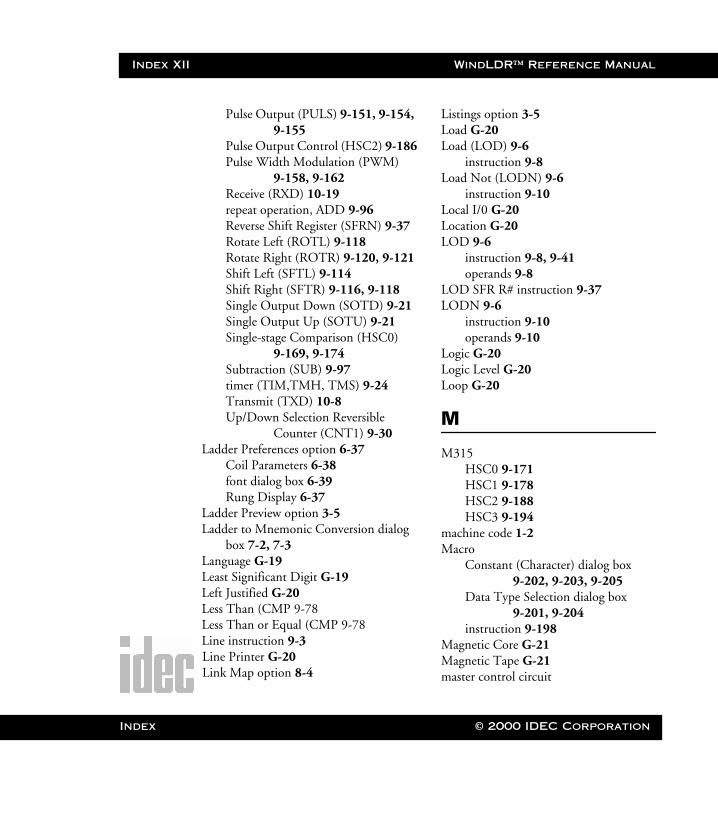
Index XII WindLDR™ Reference Manual
Index
WLDR ReferenceBook Page XII Thursday, April 5, 2001 3:36 PM
Pulse Output (PULS) 9-151, 9-154, 9-155
Pulse Output Control (HSC2) 9-186Pulse Width Modulation (PWM)
9-158, 9-162Receive (RXD) 10-19repeat operation, ADD 9-96Reverse Shift Register (SFRN) 9-37Rotate Left (ROTL) 9-118Rotate Right (ROTR) 9-120, 9-121Shift Left (SFTL) 9-114Shift Right (SFTR) 9-116, 9-118Single Output Down (SOTD) 9-21Single Output Up (SOTU) 9-21Single-stage Comparison (HSC0)
9-169, 9-174Subtraction (SUB) 9-97timer (TIM,TMH, TMS) 9-24Transmit (TXD) 10-8Up/Down Selection Reversible
Counter (CNT1) 9-30Ladder Preferences option 6-37
Coil Parameters 6-38font dialog box 6-39Rung Display 6-37
Ladder Preview option 3-5Ladder to Mnemonic Conversion dialog
box 7-2, 7-3Language G-19Least Significant Digit G-19Left Justified G-20Less Than (CMP 9-78Less Than or Equal (CMP 9-78Line instruction 9-3Line Printer G-20Link Map option 8-4
Listings option 3-5Load G-20Load (LOD) 9-6
instruction 9-8Load Not (LODN) 9-6
instruction 9-10Local I/0 G-20Location G-20LOD 9-6
instruction 9-8, 9-41operands 9-8
LOD SFR R# instruction 9-37LODN 9-6
instruction 9-10operands 9-10
Logic G-20Logic Level G-20Loop G-20
M
M315HSC0 9-171HSC1 9-178HSC2 9-188HSC3 9-194
machine code 1-2Macro
Constant (Character) dialog box 9-202, 9-203, 9-205
Data Type Selection dialog box 9-201, 9-204
instruction 9-198Magnetic Core G-21Magnetic Tape G-21master control circuit
© 2000 IDEC Corporation
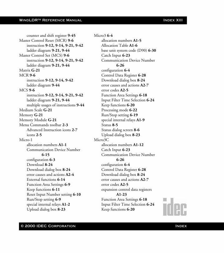
WindLDR™ Reference Manual Index XIII
WLDR ReferenceBook Page XIII Thursday, April 5, 2001 3:36 PM
counter and shift register 9-45Master Control Reset (MCR) 9-6
instruction 9-12, 9-14, 9-21, 9-42ladder diagram 9-21, 9-44
Master Control Set (MCS) 9-6instruction 9-12, 9-14, 9-21, 9-42ladder diagram 9-21, 9-44
Matrix G-21MCR 9-6
instruction 9-12, 9-14, 9-42ladder diagram 9-44
MCS 9-6instruction 9-12, 9-14, 9-21, 9-42ladder diagram 9-21, 9-44multiple usages of instructions 9-44
Medium Scale G-21Memory G-21Memory Module G-21Menu Commands toolbar 2-3
Advanced Instruction icons 2-7icons 2-5
Micro-1allocation numbers A1-1Communication Device Number
6-15configuration 6-3Download 8-24Download dialog box 8-24error causes and actions A2-4External functions 6-14Function Area Settings 6-9Keep functions 6-11Reset Input Number setting 6-10Run/Stop setting 6-9special internal relays A1-2Upload dialog box 8-23
Micro3 6-4allocation numbers A1-5Allocation Table A1-6base unit system code (D90) 6-30Catch Input 6-23Communication Device Number
6-26configuration 6-4Control Data Register 6-28Download dialog box 8-24error causes and actions A2-7error codes A2-5Function Area Settings 6-18Input Filter Time Selection 6-24Keep functions 6-20Processing mode 6-22Run/Stop setting 6-19special internal relays A1-9Status 8-5Status dialog screen 8-6Upload dialog box 8-23
Micro3Callocation numbers A1-12Catch Input 6-23Communication Device Number
6-26configuration 6-4Control Data Register 6-28Download dialog box 8-24error causes and actions A2-7error codes A2-5expansion control data registers
A1-23Function Area Settings 6-18Input Filter Time Selection 6-24Keep functions 6-20
© 2000 IDEC Corporation Index

Index XIV WindLDR™ Reference Manual
Index
WLDR ReferenceBook Page XIV Thursday, April 5, 2001 3:36 PM
Processing mode 6-22Run/Stop setting 6-19special internal relays A1-18Status 8-5Status dialog screen 8-6Upload dialog box 8-23
Micro-Processor G-21Microsecond G-21MicroSmart 1-1, 1-5
Communication dialog box 6-34Download dialog box 8-24Function Area Settings 6-34Keep functions dialog box 6-34Others dialog box 6-34Run/Stop settings dialog box 6-34Special Input dialog box 6-34Upload dialog box 8-23
MicroSmart Controller Configuration 6-7
Millisecond G-21mnemonics 1-2Mode G-21Modem G-22Monitor
Batch Monitor option 8-20Communication Error option 8-5Counters 8-15Data Registers 8-15Direct Monitor dialog box 8-14display 8-3Inputs 8-15Internal Relays 8-15Link Map option 8-4menu items 8-3mode 8-3option 8-2
Outputs 8-15Point Write dialog screen 8-17Shift Registers 8-15syntax 8-16Timers 8-15
Monitor option 8-2monitoring 1-2Monitoring Control G-22Most Significant Digit G-22MOV 9-58
instruction 9-57ladder diagram 9-58, 9-60operands 9-59repeat operation 9-61
Move (MOV) 9-58instruction 9-57ladder diagram 9-58, 9-60operands 9-59repeat operation 9-61
Move Not (MOVN) 9-58instruction 9-64ladder diagram 9-65, 9-66operands 9-65
MOVN 9-58instruction 9-64ladder diagram 9-65, 9-66operands 9-65
MULinstruction 9-92ladder diagram 9-98operands 9-94repeat operation 9-99
multi-level undo 1-2multiple ladder files 1-3multiple undos 4-2Multiplexing G-22
© 2000 IDEC Corporation

WindLDR™ Reference Manual Index XV
WLDR ReferenceBook Page XV Thursday, April 5, 2001 3:36 PM
Multiplication (MUL)instruction 9-92ladder diagram 9-98operands 9-94repeat operation 9-99
Multi-stage Comparison (HSC1)allocation numbers 9-177allocation numbers, numeric and
symbolic 9-180instruction 9-175ladder diagram 9-176, 9-182multi-stage data setting 9-179operands 9-177output delay 9-181
multi-stage data settingMulti-stage Comparison (HSC1)
9-179
N
Natural Binary G-22NEMA Standards G-22New option 3-2No Operation (NOP)
instruction 9-206Noise G-22Nonvolatile Memory G-23NOP
instruction 9-206Normally Closed (LODN)
instruction 9-10operands 9-10
Normally Open (LOD)instruction 9-8operands 9-8
NOT 9-6
instruction 9-36Not (NOT) 9-6Not Equal To (CMP)
instruction 9-78
O
Octal Numbering System G-23Off-Line G-23Ohm’s Law G-23ONC 1-1, 1-4, 1-5, 8-24
Communication Port dialog box 6-33
configuration 6-6Control Data Register 6-28Data Link dialog box 6-33Download dialog box 8-24Filter/Catch dialog box 6-33Function Area Settings 6-18, 6-32Input Filter Time Selection 6-24Keep functions 6-20Keep functions dialog box 6-32Module I/O dialog screen 6-32Open Bus dialog box 6-33Others dialog box 6-33Run/Stop setting 6-19Run/Stop settings dialog box 6-32Status 8-5Status dialog screen 8-6Upload dialog box 8-23
1 msec Timer (TMS)instruction 9-22
100 msec Timer (TIM)instruction 9-22ladder diagram 9-25
On-Line G-23
© 2000 IDEC Corporation Index
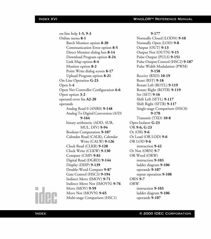
Index XVI WindLDR™ Reference Manual
Index
WLDR ReferenceBook Page XVI Thursday, April 5, 2001 3:36 PM
on-line help 1-5, 9-3Online menu 8-1
Batch Monitor option 8-20Communication Error option 8-5Direct Monitor dialog box 8-14Download Program option 8-24Link Map option 8-4Monitor option 8-2Point Write dialog screen 8-17Upload Program option 8-21
On-Line Operation G-23Open 1-4Open Net Controller Configuration 6-6Open option 3-2operand error list A2-20operands
Analog Read 0 (ANR0) 9-148Analog To Digital Conversion (A/D)
9-164binary arithmetic (ADD, SUB,
MUL, DIV) 9-94Boolean Computation 9-107Calendar Read (CALR), Calendar
Write (CALW) 9-126Clock Read (CLKR) 9-128Clock Write (CLKW) 9-130Compare (CMP) 9-81Digital Read (DGRD) 9-144Display (DISP) 9-139Double-Word Compare 9-87Gate Control (HSC3) 9-194Indirect Move (IMOV) 9-71Indirect Move Not (IMOVN) 9-76Move (MOV) 9-59Move Not (MOVN) 9-65Multi-stage Comparison (HSC1)
9-177Normally Closed (LODN) 9-10Normally Open (LOD) 9-8Output (OUT) 9-13Output Not (OUTN) 9-15Pulse Output (PULS) 9-151Pulse Output Control (HSC2) 9-187Pulse Width Modulation (PWM)
9-158Receive (RXD) 10-19Reset (RST) 9-18Rotate Left (ROTL) 9-119Rotate Right (ROTR) 9-119Set (SET) 9-16Shift Left (SFTL) 9-117Shift Right (SFTR) 9-117Single-stage Comparison (HSC0)
9-170Transmit (TXD) 10-8
Opto-Isolator G-23OR 9-6, G-23Or (OR) 9-6Or Load (OR LOD) 9-6OR LOD 9-6
instruction 9-42Or Not (ORN) 9-7OR Word (ORW)
instruction 9-103ladder diagram 9-106operands 9-107repeat operation 9-108
ORN 9-7ORW
instruction 9-103ladder diagram 9-106operands 9-107
© 2000 IDEC Corporation
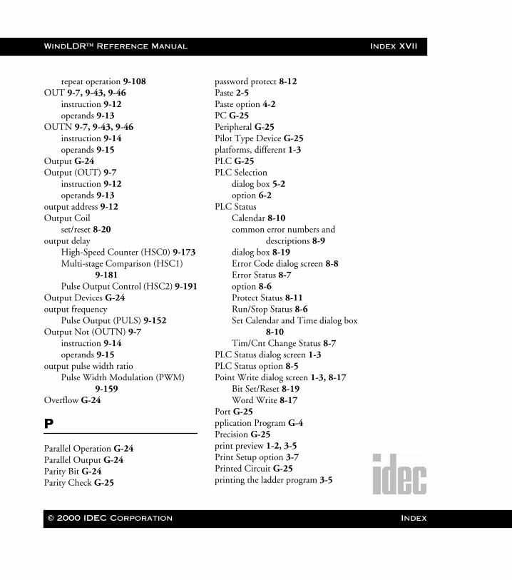
WindLDR™ Reference Manual Index XVII
WLDR ReferenceBook Page XVII Thursday, April 5, 2001 3:36 PM
repeat operation 9-108OUT 9-7, 9-43, 9-46
instruction 9-12operands 9-13
OUTN 9-7, 9-43, 9-46instruction 9-14operands 9-15
Output G-24Output (OUT) 9-7
instruction 9-12operands 9-13
output address 9-12Output Coil
set/reset 8-20output delay
High-Speed Counter (HSC0) 9-173Multi-stage Comparison (HSC1)
9-181Pulse Output Control (HSC2) 9-191
Output Devices G-24output frequency
Pulse Output (PULS) 9-152Output Not (OUTN) 9-7
instruction 9-14operands 9-15
output pulse width ratioPulse Width Modulation (PWM)
9-159Overflow G-24
P
Parallel Operation G-24Parallel Output G-24Parity Bit G-24Parity Check G-25
password protect 8-12Paste 2-5Paste option 4-2PC G-25Peripheral G-25Pilot Type Device G-25platforms, different 1-3PLC G-25PLC Selection
dialog box 5-2option 6-2
PLC StatusCalendar 8-10common error numbers and
descriptions 8-9dialog box 8-19Error Code dialog screen 8-8Error Status 8-7option 8-6Protect Status 8-11Run/Stop Status 8-6Set Calendar and Time dialog box
8-10Tim/Cnt Change Status 8-7
PLC Status dialog screen 1-3PLC Status option 8-5Point Write dialog screen 1-3, 8-17
Bit Set/Reset 8-19Word Write 8-17
Port G-25pplication Program G-4Precision G-25print preview 1-2, 3-5Print Setup option 3-7Printed Circuit G-25printing the ladder program 3-5
© 2000 IDEC Corporation Index
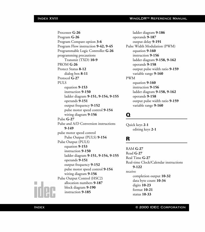
Index XVIII WindLDR™ Reference Manual
Index
WLDR ReferenceBook Page XVIII Thursday, April 5, 2001 3:36 PM
Processor G-26Program G-26Program Compare option 3-6Program Flow instruction 9-42, 9-45Programmable Logic Controller G-26programming precautions
Transmit (TXD) 10-9PROM G-26Protect Status 8-12
dialog box 8-11Protocol G-27PULS
equation 9-153instruction 9-150ladder diagram 9-151, 9-154, 9-155operands 9-151output frequency 9-152pulse motor speed control 9-154wiring diagram 9-156
Pulse G-27Pulse and A/D Conversion instructions
9-149pulse motor speed control
Pulse Output (PULS) 9-154Pulse Output (PULS)
equation 9-153instruction 9-150ladder diagram 9-151, 9-154, 9-155operands 9-151output frequency 9-152pulse motor speed control 9-154wiring diagram 9-156
Pulse Output Control (HSC2)allocation numbers 9-187block diagram 9-190instruction 9-185
ladder diagram 9-186operands 9-187output delay 9-191
Pulse Width Modulation (PWM)equation 9-160instruction 9-156ladder diagram 9-158, 9-162operands 9-158output pulse width ratio 9-159variable range 9-160
PWMequation 9-160instruction 9-156ladder diagram 9-158, 9-162operands 9-158output pulse width ratio 9-159variable range 9-160
Q
Quick keys 2-1editing keys 2-1
R
RAM G-27Read G-27Real Time G-27Real-time Clock/Calendar instructions
9-122receive
completion output 10-32data byte count 10-34digits 10-23format 10-21status 10-33
© 2000 IDEC Corporation
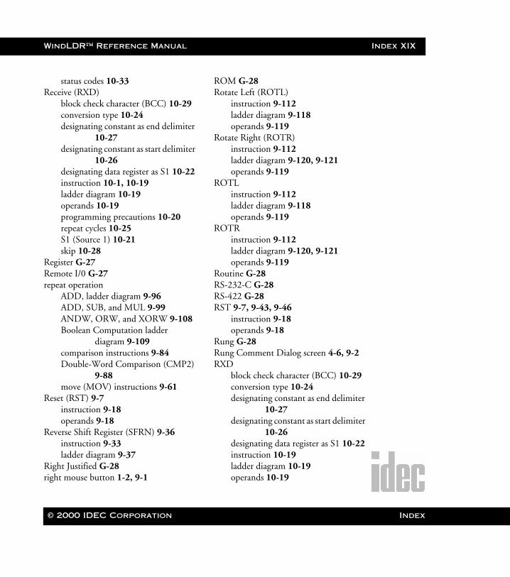
WindLDR™ Reference Manual Index XIX
WLDR ReferenceBook Page XIX Thursday, April 5, 2001 3:36 PM
status codes 10-33Receive (RXD)
block check character (BCC) 10-29conversion type 10-24designating constant as end delimiter
10-27designating constant as start delimiter
10-26designating data register as S1 10-22instruction 10-1, 10-19ladder diagram 10-19operands 10-19programming precautions 10-20repeat cycles 10-25S1 (Source 1) 10-21skip 10-28
Register G-27Remote I/0 G-27repeat operation
ADD, ladder diagram 9-96ADD, SUB, and MUL 9-99ANDW, ORW, and XORW 9-108Boolean Computation ladder
diagram 9-109comparison instructions 9-84Double-Word Comparison (CMP2)
9-88move (MOV) instructions 9-61
Reset (RST) 9-7instruction 9-18operands 9-18
Reverse Shift Register (SFRN) 9-36instruction 9-33ladder diagram 9-37
Right Justified G-28right mouse button 1-2, 9-1
ROM G-28Rotate Left (ROTL)
instruction 9-112ladder diagram 9-118operands 9-119
Rotate Right (ROTR)instruction 9-112ladder diagram 9-120, 9-121operands 9-119
ROTLinstruction 9-112ladder diagram 9-118operands 9-119
ROTRinstruction 9-112ladder diagram 9-120, 9-121operands 9-119
Routine G-28RS-232-C G-28RS-422 G-28RST 9-7, 9-43, 9-46
instruction 9-18operands 9-18
Rung G-28Rung Comment Dialog screen 4-6, 9-2RXD
block check character (BCC) 10-29conversion type 10-24designating constant as end delimiter
10-27designating constant as start delimiter
10-26designating data register as S1 10-22instruction 10-19ladder diagram 10-19operands 10-19
© 2000 IDEC Corporation Index
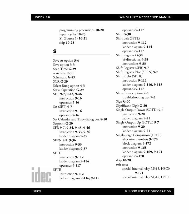
Index XX WindLDR™ Reference Manual
Index
WLDR ReferenceBook Page XX Thursday, April 5, 2001 3:36 PM
programming precautions 10-20repeat cycles 10-25S1 (Source 1) 10-21skip 10-28
S
Save As option 3-4Save option 3-3Scan Time G-29scan time 9-50Schematic G-29SCR G-29Select Rung option 4-3Serial Operation G-29SET 9-7, 9-43, 9-46
instruction 9-16operands 9-16
Set (SET) 9-7instruction 9-16operands 9-16
Set Calendar and Time dialog box 8-10Setpoint G-29SFR 9-7, 9-34, 9-43, 9-46
instruction 9-33, 9-36ladder diagram 9-35
SFRN 9-7, 9-36instruction 9-33ladder diagram 9-37
SFTLinstruction 9-112ladder diagram 9-114operands 9-117
SFTRinstruction 9-112ladder diagram 9-116, 9-118
operands 9-117Shift G-30Shift Left (SFTL)
instruction 9-112ladder diagram 9-114operands 9-117
Shift Register G-30bi-directional 9-38instructions 9-33
Shift Register (SFR) 9-7Shift Register Not (SFRN) 9-7Shift Right (SFTR)
instruction 9-112ladder diagram 9-116, 9-118operands 9-117
Show Errors option 7-3troubleshooting tips 7-3
Sign G-30Significant Digit G-30Single Output Down (SOTD) 9-7
instruction 9-20ladder diagram 9-21
Single Output Up (SOTU) 9-7instruction 9-20ladder diagram 9-21
Single-stage Comparison (HSC0)allocation numbers 9-170block diagram 9-172instruction 9-168ladder diagram 9-169, 9-174operands 9-170
skip 10-28soft reset
special internal relay M315, HSC0 9-171
special internal relay M315, HSC1
© 2000 IDEC Corporation
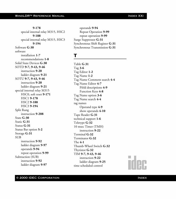
WindLDR™ Reference Manual Index XXI
WLDR ReferenceBook Page XXI Thursday, April 5, 2001 3:36 PM
9-178special internal relay M315, HSC2
9-188special internal relay M315, HSC3
9-194Software G-30software
installation 1-7recommendations 1-8
Solid State Devices G-30SOTD 9-7, 9-43, 9-46
instruction 9-20ladder diagram 9-21
SOTU 9-7, 9-43, 9-46instruction 9-20ladder diagram 9-21
special internal relay M315HSC0, soft reset 9-171HSC1 9-178HSC2 9-188HSC3 9-194
Split Runginstruction 9-208
State G-30Static G-31Status G-31Status Bar option 5-2Storage G-31SUB
instruction 9-92ladder diagram 9-97operands 9-94repeat operation 9-99
Subtraction (SUB)instruction 9-92ladder diagram 9-97
operands 9-94Repeat Operation 9-99repeat operation 9-99
Surge Suppressor G-31Synchronous Shift Register G-31Synchronous Transmission G-31
T
Table G-31Tag 3-6Tag Editor 1-2Tag Name 1-2Tag Name Comment search 4-4Tag Name Editor 4-7
Ffeld descriptions 4-9Function Keys 4-8
Tag Name option 3-6Tag Name search 4-4tag names
Operand type 4-9show operands 4-10
Tape Reader G-31technical support 1-6Teletype G-3210 msec Timer (TMH)
instruction 9-22Terminal G-32Terminator G-32The 4-1Thumb-Wheel Switch G-32Thyristor G-32TIM 9-7, 9-43, 9-46
instruction 9-22ladder diagram 9-25
time scheduled control
© 2000 IDEC Corporation Index
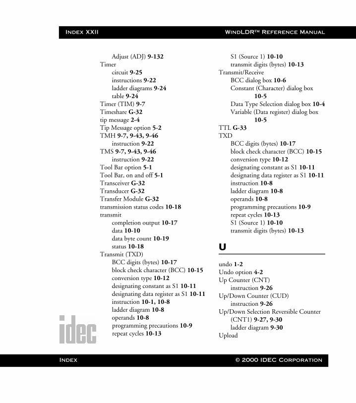
Index XXII WindLDR™ Reference Manual
Index
WLDR ReferenceBook Page XXII Thursday, April 5, 2001 3:36 PM
Adjust (ADJ) 9-132Timer
circuit 9-25instructions 9-22ladder diagrams 9-24table 9-24
Timer (TIM) 9-7Timeshare G-32tip message 2-4Tip Message option 5-2TMH 9-7, 9-43, 9-46
instruction 9-22TMS 9-7, 9-43, 9-46
instruction 9-22Tool Bar option 5-1Tool Bar, on and off 5-1Transceiver G-32Transducer G-32Transfer Module G-32transmission status codes 10-18transmit
completion output 10-17data 10-10data byte count 10-19status 10-18
Transmit (TXD)BCC digits (bytes) 10-17block check character (BCC) 10-15conversion type 10-12designating constant as S1 10-11designating data register as S1 10-11instruction 10-1, 10-8ladder diagram 10-8operands 10-8programming precautions 10-9repeat cycles 10-13
S1 (Source 1) 10-10transmit digits (bytes) 10-13
Transmit/ReceiveBCC dialog box 10-6Constant (Character) dialog box
10-5Data Type Selection dialog box 10-4Variable (Data register) dialog box
10-5TTL G-33TXD
BCC digits (bytes) 10-17block check character (BCC) 10-15conversion type 10-12designating constant as S1 10-11designating data register as S1 10-11instruction 10-8ladder diagram 10-8operands 10-8programming precautions 10-9repeat cycles 10-13S1 (Source 1) 10-10transmit digits (bytes) 10-13
U
undo 1-2Undo option 4-2Up Counter (CNT)
instruction 9-26Up/Down Counter (CUD)
instruction 9-26Up/Down Selection Reversible Counter
(CNT1) 9-27, 9-30ladder diagram 9-30
Upload
© 2000 IDEC Corporation
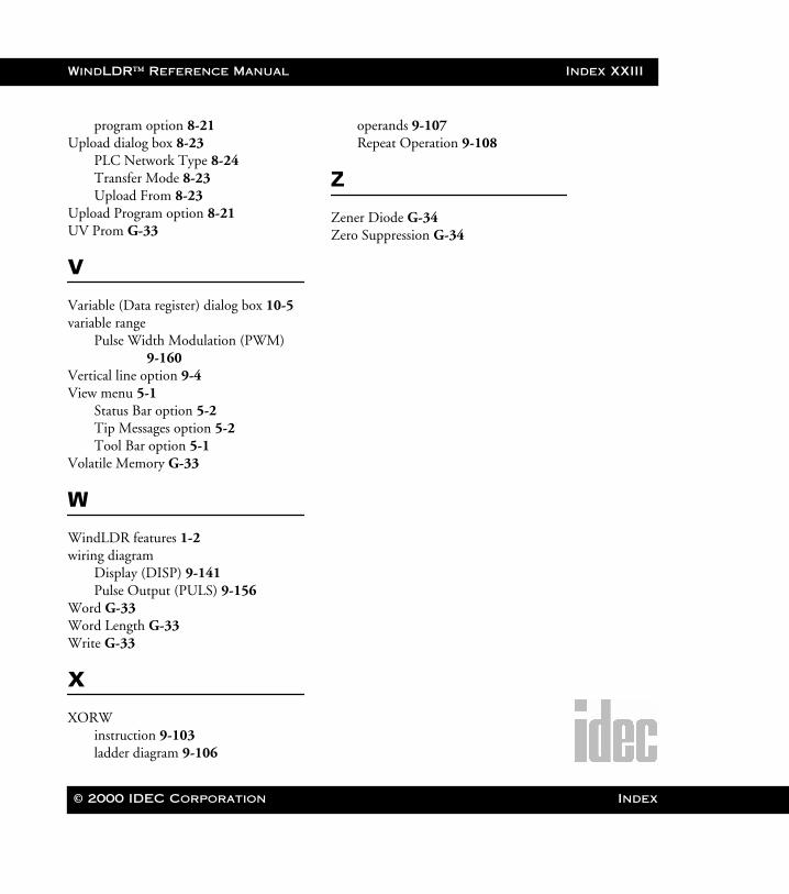
WindLDR™ Reference Manual Index XXIII
WLDR ReferenceBook Page XXIII Thursday, April 5, 2001 3:36 PM
program option 8-21Upload dialog box 8-23
PLC Network Type 8-24Transfer Mode 8-23Upload From 8-23
Upload Program option 8-21UV Prom G-33
V
Variable (Data register) dialog box 10-5variable range
Pulse Width Modulation (PWM) 9-160
Vertical line option 9-4View menu 5-1
Status Bar option 5-2Tip Messages option 5-2Tool Bar option 5-1
Volatile Memory G-33
W
WindLDR features 1-2wiring diagram
Display (DISP) 9-141Pulse Output (PULS) 9-156
Word G-33Word Length G-33Write G-33
X
XORWinstruction 9-103ladder diagram 9-106
operands 9-107Repeat Operation 9-108
Z
Zener Diode G-34Zero Suppression G-34
© 2000 IDEC Corporation Index

WindLDR™ Reference Manual
WLDR ReferenceBook Page XXIV Thursday, April 5, 2001 3:36 PM
© 2000 IDEC Corporation