Reference architectures for highly automated...
68
REFERENCE ARCHITECTURES FOR HIGHLY AUTOMATED DRIVING sagar behere doctoral thesis in machine design kth royal institute of technology stockholm, sweden, 2016
Transcript of Reference architectures for highly automated...
R E F E R E N C E A R C H I T E C T U R E S F O R H I G H LY A U T O M AT E DD R I V I N G
sagar behere
doctoral thesis in machine design
kth royal institute of technology
stockholm, sweden, 2016

Cover illustration: The complexity of architecture
The image shows a subset of data flows in the system architecture ofa heavy commercial truck made by Scania CV AB, Sweden. Nodesrepresent logical functions, edges represent inter-function communi-cation. There are ca. 1500 nodes and 5000 edges. Nodes are clusteredby ECUs.
Image courtesy: Viktor Kaznov, Systems Architect, Scania CV AB
TRITA-MMK 2015:09 KTH School of IndustrialISSN 1400-1179 Engineering and ManagementISRN KTH/MMK/R-15/09-SE 100 44 StockholmISBN 978-91-7595-757-9 Sweden
Academic thesis, which with the approval of KTH Royal Institute ofTechnology, will be presented for public review in fulfillment of therequirements for a Doctorate of Technology in Machine Design. Thepublic review is held in room Kollegiesalen, Brinellvägen 8, 100 44
Stockholm, Sweden on 2016-01-22 at 09:00.
© Sagar Behere, 2016
Typeset with LATEXusing the classicthesis template by André Miede.Print: Universitetsservice US AB

I see God inthe instruments and the mechanisms that
work reliably,more reliably than the limited sensory departments of
the human mechanism.
— R. Buckminster Fuller, Whole Earth Catalog

A B S T R A C T
Highly automated driving systems promise increased road trafficsafety, as well as positive impacts on sustainable transportation bymeans of increased traffic efficiency and environmental friendliness.The design and development of such systems require scientific ad-vances in a number of areas. One area is the vehicle’s electrical/elec-tronic (E/E) architecture. The E/E architecture can be presented us-ing a number of views, of which an important one is the functionalview. The functional view describes the decomposition of the systeminto its main logical components, along with the hierarchical struc-ture, the component inter-connections, and requirements. When thisview captures the principal ideas and patterns that constitute thefoundation of a variety of specific architectures, it may be termedas a reference architecture. Two reference architectures for highly au-tomated driving form the principal contribution of this thesis. Thefirst reference architecture is for cooperative driving. In a cooperativedriving situation, vehicles and road infrastructure in the vicinity ofa vehicle continuously exchange wireless information and this infor-mation is then used to control the motion of the vehicle. The secondreference architecture is for autonomous driving, wherein the vehicleis capable of driver-less operation even without direct communica-tion with external entities. The description of both reference archi-tectures includes their main components and the rationale for howthese components should be distributed across the architecture andits layers. These architectures have been validated via multiple real-world instantiations, and the guidelines for instantiation also formpart of the architecture description. A comparison with similar archi-tectures is also provided, in order to highlight the similarities and dif-ferences. The comparisons show that in the context of automated driv-ing, the explicit recognition of components for semantic understand-ing, world modeling, and vehicle platform abstraction are uniqueto the proposed architecture. These components are not unusual inarchitectures within the Artificial Intelligence/robotics domains; theproposed architecture shows how they can be applied within the au-tomotive domain. A secondary contribution of this thesis is a descrip-tion of a lightweight, four step approach for model based systemsengineering of highly automated driving systems, along with sup-porting model classes. The model classes cover the concept of op-erations, logical architecture, application software components, andthe implementation platforms. The thesis also provides an overviewof current implementation technologies for cognitive driving intelli-gence and vehicle platform control, and recommends a specific setup
v

for development and accelerated testing of highly automated drivingsystems, that includes model- and hardware-in-the-loop techniquesin conjunction with a publish/subscribe bus. Beyond the more "tradi-tional" engineering concepts, the thesis also investigates the domainof machine consciousness and computational self-awareness. The ex-ploration indicates that current engineering methods are likely to hita complexity ceiling, breaking through which may require advances inhow safety-critical systems can self-organize, construct, and evaluateinternal models to reflect their perception of the world. Finally, thethesis also presents a functional architecture for the brake system ofan autonomous truck. This architecture proposes a reconfigurationof the existing brake systems of the truck in a way that providesdynamic, diversified redundancy, and an increase in the system relia-bility and availability, while meeting safety requirements.
vi
S A M M A N FAT T N I N G
Högautomatiserade fordonssystem ger förhoppningar om ökad trafik-säkerhet samt positiva effekter för hållbara transporter genom ökadtrafikeffektivitet och miljövänlighet. Design och utveckling av sys-temen kräver vetenskapliga framsteg i flera områden. Ett områdeär fordonets elektriska/elektroniska (E/E) arkitektur. E/E arkitek-turen kan presenteras med hjälp ett antal vyer; denna avhandlingfokuserar på den funktionella vyn. Den funktionella vyn beskrivernedbrytningen av systemet i dess huvudsakliga logiska komponen-ter, tillsammans med den hierarkiska strukturen, komponentinterna-anslutningar, gränssnitt och krav. När denna vy sammanlänkas medprinciper och mönster som utgör grunden för en mängd olika speci-fika arkitekturer, kan den betecknas som en referensarkitektur. Tvåreferensarkitekturer för högautomatiserad körning utgör det huvud-sakliga bidraget i denna avhandling. Den första referensarkitekturenär för kooperativ körning. I en kooperativ körsituation sker kontin-uerligt utbyte av trådlös information mellan fordon och väginfras-truktur i närheten av fordonet, denna information används sedanför att styra fordonets rörelse. Den andra referensarkitekturen är förautonom körning, varvid fordonet kan köras förarlöst även utan di-rekt kommunikation med externa enheter. Beskrivningen av de bådareferensarkitekturerna inkluderar deras huvudkomponenter och mo-tiven för hur dessa komponenter bör fördelas över arkitekturen ochdess skikt. Arkitekturerna har validerats via flera verklighetsbaser-ade instansieringar och riktlinjerna för instansiering ingår också somen del av arkitekturens beskrivning. Referensarkitekturerna har jäm-förts med liknande arkitekturer i syfte att lyfta fram likheter och skill-nader. Jämförelserna visar att explicit inkludering av komponenterför semantisk förståelse, världsmodellering och fordonsplattformsab-straktion är unika för de föreslagna arkitekturerna i kontexten au-tomatiserad körning. Dessa komponenter är inte ovanliga i arkitek-turer inom artificiell intelligens-/robotik; de föreslagna arkitektur-erna visar hur de kan tillämpas inom fordonsdomänen. Ytterligareett bidrag i avhandlingen är en beskrivning av en lättviktsmetodi fyra steg för modellbaserad systemkonstruktion av högautomatis-erade körsystem, tillsammans med stödjande modellklasser. Model-lklasserna omfattar begreppen aktiviteter, logisk arkitektur, applika-tionsprogramvarukomponenter och plattformar för implementering.Avhandlingen ger också en översikt av aktuell teknik för realiseringav artificiell intelligens och fordonsplattform, och rekommenderarspecifika metoder för utveckling och accelererad testning av högau-tomatiserade körsystem. Dessa metoder inkluderar modell- och hård-varu återkopplingsteknik (eng. ”hardware-in-the loop”) tillsammans
vii

med publicerings/prenumerations kommunikation. Bortom de mer"traditionella" tekniska koncepten, utforskar avhandlingen även om-rådet för maskinmedvetande och medvetenhet. Undersökningen visaratt nuvarande tekniska metoder sannolikt kommer att nå ett komplex-itetstak. För ett genombrott krävs framsteg inom hur säkerhetskri-tiska system kan självorganisera sig samt konstruera och utvärderainterna modeller för att spegla sin uppfattning om världen. Slutli-gen presenterar avhandlingen en funktionell arkitektur för bromssys-temet för en autonom lastbil. Arkitekturen föreslår en omkonfigureringav de befintliga bromssystem hos lastbilen på ett sätt som tillhan-dahåller dynamisk, diversifierad redundans och en ökning av sys-temtillförlitlighet och -tillgänglighet.
viii

A P P E N D E D P U B L I C AT I O N S
PUBLICATION A
Architecture challenges for intelligent autonomous machines: An industrialperspective
Sagar Behere, Fredrik Asplund, Andreas Söderberg, Martin Törngren
Proceedings of the 13th International Conference on Intelligent Au-
tonomous Systems (IAS-13). Advances in Intelligent Systems and Com-puting, Springer International Publishing, 2015. ISBN: 9783319083384
Sagar wrote the text. Fredrik and Andreas edited and provided insightson safety related topics. Martin assisted in organizing the paper structure,reviewed and provided feedback.
PUBLICATION B
The Development of a Cooperative Heavy-Duty Vehicle for the GCDC 2011:Team Scoop
Mårtensson, J. ; Behere, S. et al
IEEE Transactions on Intelligent Transportation Systems, vol. 13, no.3, pp.1033-1049, September 2012 doi: 10.1109/TITS.2012.2204876
Sagar wrote section II on Architecture. Other authors wrote sections abouttheir individual work related to control, communications, etc.
PUBLICATION C
A reference architecture for cooperative driving
Sagar Behere, Martin Törngren, De-Jiu Chen
Journal of Systems Architecture, Vol. 59, Issue 10, Part C, November2013, Pages 1095-1112 DOI: 10.1016/j.sysarc.2013.05.014
Sagar wrote the text. Martin and Chen reviewed and provided feedback.
ix

PUBLICATION D
A functional reference architecture for autonomous driving
Sagar Behere, Martin Törngren
[accepted] Journal of Information and Software TechnologyElsevier BV. Extended version of publication L.
Sagar wrote the text. Martin reviewed and provided feedback.
PUBLICATION E
Systems engineering and architecting for autonomous driving
Sagar Behere, Martin Törngren
[accepted] Chapter in book "Automated Driving - Safer and moreefficient future driving", Springer International Publishing AG (to bepublished in early 2016)
Sagar wrote the text. Martin edited, reviewed and provided feedback.
PUBLICATION F
A functional brake architecture for autonomous heavy commercial vehicles
Sagar Behere, Viacheslav Izosimov, Xinhai Zhang, Martin Törngren
[submitted] SAE World Congress , 2016
Sagar wrote most of the text. Viacheslav edited content on hazard analysisand ISO26262. Xinhai helped with simulations. Martin reviewed and pro-vided feedback.
PUBLICATION G
Architecture support for automobile autonomy: A state of the art survey
Sagar Behere
Technical report, 2015, Dept. of Machine DesignKTH TRITA - MMK 2015:08, ISSN 1400-1179
ISRN/KTH/MMK/R15/08-SE
x

O T H E R P U B L I C AT I O N S
PUBLICATION H
Educating embedded system hackers: A practitioner’s perspective
Sagar Behere, Martin Törngren
Proceedings of the Workshop on Embedded Systems Education (WESE)2014, ACM Publications
Sagar wrote the text. Martin reviewed and provided feedback.
PUBLICATION I
Educating embedded system hackers: A practitioner’s perspective
Sagar Behere, Martin Törngren
[accepted] SIGBED Review, special edition on education. Extendedversion of publication H.
Sagar wrote the text. Martin reviewed and provided feedback.
PUBLICATION J
Towards autonomous embedded systems
Sagar Behere, Martin Törngren, Jad El-khoury, De-Jiu Chen
First Open EIT ICT Labs Workshop on Cyber-Physical Systems Engi-neering (EIT CPSE) 2013, Trento, Italy
Sagar wrote the text. Others reviewed and provided feedback.
xi

PUBLICATION K
Cooperative driving according to Scoop
Alam A., Behere S. et al
Real-Time in Sweden (RTiS) 2011, Västerås, Sweden
Sagar wrote the text. Martin reviewed and provided feedback.
PUBLICATION L
A functional architecture for autonomous driving
Sagar Behere, Martin Törngren
First international Workshop on Automotive Software Architectures(WASA) 2015, Montréal, Canada
Sagar wrote the text. Martin reviewed and provided feedback.
PUBLICATION M
Scoop Technical Report: Year 2011
Sagar Behere
Technical report, 2011, Dept. of Machine DesignKTH TRITA - MMK2012:12, ISSN 1400-1179
ISRN/KTH/MMK/R-12/12-SE
xii

A C K N O W L E D G M E N T S
On a cold winter morning during my early PhD efforts, I was skatingover the frozen Brunnsviken lake together with my supervisor, Mar-tin Törngren. Martin set forth at a tremendous speed, while I clungto his outstretched hand and let myself be dragged along behind,going, "Wheeeeeee". That has pretty much been the metaphor for thisPhD work. Under Martin’s nurturing guidance and encouragement, Ilearned to skate, and sometimes overstretched and ended up on thinice. The metaphor with the PhD work still holds.
De-Jiu Chen could always help me to find the right words to ex-press my thinking. Discussing research ideas with Chen is like drink-ing from a firehose.
Jad El-khoury guided me through my licentiate thesis with refresh-ing bluntness. His approach to planning, organization, and allocationof responsibility has since become a part of my own programming.
Martin Grimheden and Jan Wikander are supporters of dreams.Their positive influence has undoubtedly exceeded the awareness Ihave of their efforts.
Frédéric Loiret is the kind of guy with whom you can discuss any-thing and everything. Conversations with him spiced up my world,and his vigor and enthusiasm pulled me through many a dark period.
Xinhai Zhang is a quiet, reticent guy until you need his help. Thenhe grows into a giant whom you can solidly rely on. Be it brake sys-tem simulations or moving heavy boxes around, Xinhai unhesitat-ingly came to my aid.
Katja Gradin’s company is superior even to coffee and cake, imag-ine that. Realizing that she genuinely cares about me, left me feelingoverwhelmed more often than I admitted.
Didem Gürdür attempted to educate me on feminism, veganism,activism, and other -isms. She made a difference, while toleratingmy teasing. Daniel Frede, Mohammad Khodabakhshian, Fredrik As-plund, and Daniel Malmquist tolerated my gratuitous interruptionsto their work with grace. I gleefully disturbed them whenever I feltthe itch to survey the social state of the art.
At Scania, Per Roos, Viktor Kaznov, and Johan Svahn, better knownas the three musketeers, provided a "home away from home" for myresearch. The launch of the ARCHER project is an eloquent testimonyto the synergy of our work. As well, the colleagues at the Volvo CarCorporation and others in the DFEA2020 and FUSE projects enrichedthis research with industrial insights.
In a league of their own, are my parents and sister — for their re-lentless love and support. Without you, life itself would be pointless.
xiii

C O N T E N T S
1 introduction 1
1.1 Background 1
1.2 Thesis scope and relevance 5
1.3 Methodology 6
1.4 Hypothesis and research question 10
1.5 Overview of contributions 12
1.6 Impact 14
2 reading guide and contributions 17
2.1 Reading guide — Publications 17
2.2 Frame of reference 18
2.3 Executive summary of contributions 21
2.3.1 Architecture challenges for intelligent autonomousmachines ([A]) 22
2.3.2 Platooning and cooperative driving ([B] and [C]) 25
2.3.3 Autonomous driving ([D] and [E]) 30
2.3.4 Model based systems engineering ([E]) 34
2.3.5 The context of machine consciousness ([E]) 36
2.3.6 A brake architecture for autonomous trucks ([F]) 38
3 discussion 43
3.1 Future work 46
bibliography 49
xv

L I S T O F F I G U R E S
Figure 1 SAE levels of automated driving [4] 2
Figure 2 Some areas contributing to highly automateddriving 3
Figure 3 Thesis context — main contributions are in func-tional architecture 6
Figure 4 Prototypes created during the thesis work 8
Figure 5 Categories of thesis contributions 13
Figure 6 Frame of reference for automated driving ar-chitectures 18
Figure 7 Scoop architecture: Logical functions 26
Figure 8 Scoop architecture: Hardware view 27
Figure 9 Scoop architecture: Implementation view 27
Figure 10 A reference architecture for cooperative driv-ing 29
Figure 11 Main functional components for autonomousdriving 30
Figure 12 A functional reference architecture for autonomousdriving 33
Figure 13 Systems engineering model classes 34
Figure 14 Partial view of modeling artifacts and alloca-tion links 35
Figure 15 General pattern for brake architecture 39
Figure 16 Mapping from existing brake architecture togeneral pattern 40
Figure 17 Simulation of ’Omission’ condition in primarybrake (at 2.6s mark, note no reduction in speed) 41
xvi
G L O S S A RY
adl Architecture Description Language. A computer language usedto create a description of a system architecture.
architecture A system’s blueprint as reflected in the key build-ing blocks of the system, their composition, their interplay, theresulting extra-functional properties, and so on. More formally,it is defined within a systems engineering context by ISO 42010
as, "..fundamental concepts or properties of a system in its en-vironment, embodied in its elements, relationships, and in theprinciples of its design and evolution." [3]
artificial intelligence The science and engineering of makingintelligent machines, especially intelligent computer programs[12].
automated driving system The hardware and software that iscollectively capable of performing all aspects of the dynamicdriving task for a vehicle (whether part time or full time) [4].
automotive e/e architecture The architecture of an automo-bile’s Electrical/Electronic systems. It includes computing hard-ware, software, communication links as well as functional hier-archies and their distribution across the architecture.
autonomous machines Machines which can perform their task(s)with no (or minimal) human intervention. Based on definitionof Intelligent Autonomous Machine found in [13]
complex system A system that can be analyzed into many compo-nents having relatively many relations among them, so that thebehavior of some components may depend on the behavior ofothers, and the behavior of the system cannot simply be derivedfrom the summation of individual components’ behavior. Basedon definition in [17]
consciousness The fact of awareness by the mind of itself andthe world, where awareness is further defined as knowledge orperception of a situation or fact [15].
cooperative driving Driving in a situation where vehicles androad infrastructure in the vicinity of a vehicle continuously ex-change wireless information, and where this information is thenused to control the motion of the vehicle.
ecu Electronic Control Unit. Typically, an embedded computer con-trolling one or more vehicle functions.
xvii

xviii glossary
embedded system A computer system that is part of a larger sys-tem and performs some of the requirements of that system [2].
functional architecture view The functional architecture viewdescribes the decomposition of the system into its main logicalcomponents, along with the hierarchical structure, the compo-nent inter-connections, interfaces, and data-flows. The descrip-tion is made without prejudice to any particular technologicalimplementation. This description is written in the flavor of ISO42010 [3]
intelligence The ability of a system to act appropriately in anuncertain environment, where appropriate action is that whichincreases the probability of success, and success is the achieve-ment of behavioral subgoals that support the system’s ultimategoal. [5]
mbse Model Based Systems Engineering - the formalized applicationof modeling to support system requirements, design, analysis,verification and validation activities beginning in the conceptualdesign phase and continuing throughout development and laterlife cycle phases [9].
reference architecture A predefined architectural pattern, orset of patterns, possibly partially or completely instantiated, de-signed, and proven for use in particular business and technicalcontexts, together with supporting artifacts to enable their use[11].
system A set of elements in interaction [18]. More specifically, anengineered system is defined as an interacting combination of el-ements to accomplish a defined objective. These include hard-ware, software, firmware, people, information, techniques, facil-ities, services, and other support elements [10].
systems engineering Systems Engineering is an interdisciplinaryapproach and means to enable the realization of successful sys-tems. It focuses on defining customer needs and required func-tionality early in the development cycle, documenting require-ments, then proceeding with design synthesis and system vali-dation while considering the complete problem [8].
tvvq Testing, Verification, Validation, Qualification
1I N T R O D U C T I O N
"Begin at the beginning," theKing said gravely, "and go ontill you come to the end: thenstop."
— Lewis Carroll, Alice inWonderland
1.1 background
In recent years, technologies that reduce (or eliminate) the need ofhuman intervention in the control of machines, have steadily gainedmomentum. The application of such technologies in the automotivedomain has resulted in Advanced Driver Assistance Systems (ADAS)such as Adaptive Cruise Control (ACC), Lane Keeping Assist (LKA),Automatic Emergency Braking (AEB), and Traffic Jam Assist (TJA).Such systems control (parts of) the vehicle motion in scenarios wherehuman control performance can be improved upon. Technology trendsin ADAS systems point to a future where road vehicles which may nolonger require human drivers. The elimination of human drivers hasthe potential to improve safety of road traffic, because human behav-ior and limitations are the cause of almost 94% [14] of incidents thatcompromise road safety. Beyond safety, improvements in comfort,traffic throughput, and eco-friendliness are also expected. Towardsthese ends, numerous vehicle prototypes have been built, which re-quire no human driver intervention when operating in specific condi-tions. Such vehicles are commonly referred to as "self-driving", "driver-less", "autonomous", "unmanned", or "robotic" in vernacular English.This thesis is concerned with the design and development of suchvehicles.
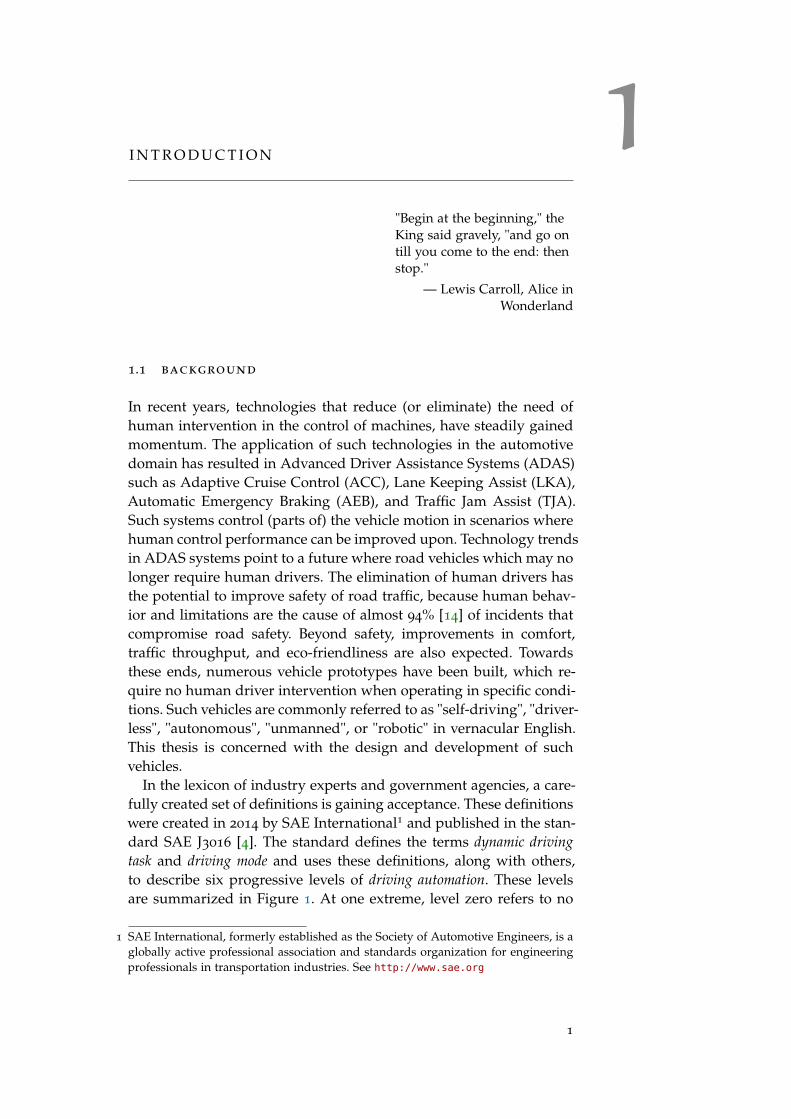
In the lexicon of industry experts and government agencies, a care-fully created set of definitions is gaining acceptance. These definitionswere created in 2014 by SAE International1 and published in the stan-dard SAE J3016 [4]. The standard defines the terms dynamic drivingtask and driving mode and uses these definitions, along with others,to describe six progressive levels of driving automation. These levelsare summarized in Figure 1. At one extreme, level zero refers to no
1 SAE International, formerly established as the Society of Automotive Engineers, is aglobally active professional association and standards organization for engineeringprofessionals in transportation industries. See http://www.sae.org
1
2 introduction
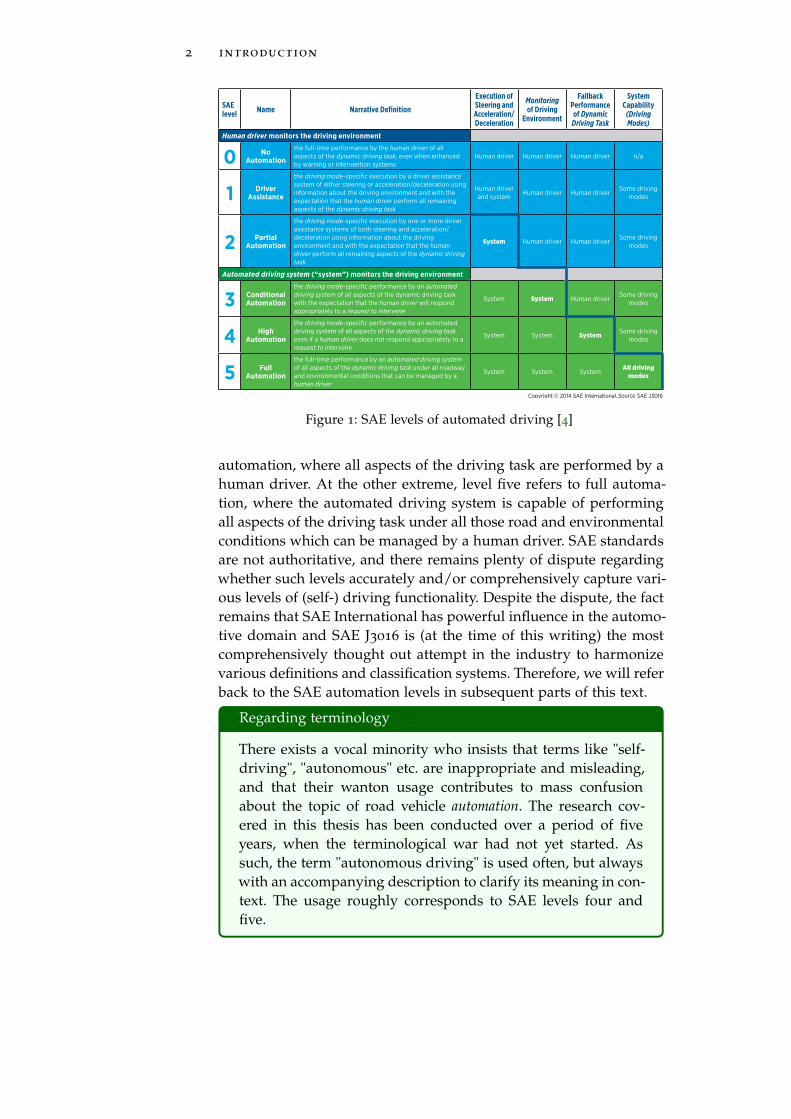
Figure 1: SAE levels of automated driving [4]
automation, where all aspects of the driving task are performed by ahuman driver. At the other extreme, level five refers to full automa-tion, where the automated driving system is capable of performingall aspects of the driving task under all those road and environmentalconditions which can be managed by a human driver. SAE standardsare not authoritative, and there remains plenty of dispute regardingwhether such levels accurately and/or comprehensively capture vari-ous levels of (self-) driving functionality. Despite the dispute, the factremains that SAE International has powerful influence in the automo-tive domain and SAE J3016 is (at the time of this writing) the mostcomprehensively thought out attempt in the industry to harmonizevarious definitions and classification systems. Therefore, we will referback to the SAE automation levels in subsequent parts of this text.
Regarding terminology
There exists a vocal minority who insists that terms like "self-driving", "autonomous" etc. are inappropriate and misleading,and that their wanton usage contributes to mass confusionabout the topic of road vehicle automation. The research cov-ered in this thesis has been conducted over a period of fiveyears, when the terminological war had not yet started. Assuch, the term "autonomous driving" is used often, but alwayswith an accompanying description to clarify its meaning in con-text. The usage roughly corresponds to SAE levels four andfive.

1.1 background 3
The development of highly automated driving systems and theirintroduction into mass markets in the form of consumer products,require progress in broadly four different areas, as shown in Figure2.
Figure 2: Some areas contributing to highly automated driving
algorithms The formal mathematical knowledge for solving spe-cific problems in a sequence of computation steps
architecture and implementation technologies The designand realization of systems which utilize the algorithms to per-form desired functional tasks, while meeting other requirementssuch as modularity and reliability.
systems engineering The systematic methods and processes usedto construct systems

4 introduction
societal/regulatory Regulatory and legal frameworks to per-mit system operation, including topics related to liability, insur-ance etc.
Within each of these areas lies a practically endless scope for re-search. The most relevant areas for this thesis are architecture and sys-tems engineering, whose sub-areas are shown in the outer half-circleof Figure 2 (Representation, Simulation, ... , Verification & Validation).The development of architectures is supported by research for repre-sentation of those architectures. The representation is usually in theform of a set of models. The models may capture different aspectsof the system and facilitate different types of simulations and analy-ses, for example, safety. Similarly, development process are supportedby work tasks that create and maintain various types of artifacts, forexample requirements, and further sub-processes for activities liketesting, verification and validation. The system artifacts as well as therelated work tasks are often highly interdependent. For example, canan architecture model be linked with a set of requirements, such thata change in either the model or the requirements can be propagatedfrom the one to the other? Or, can the architecture be represented insuch a way that it is possible to automatically generate software codefrom that representation? And what development process would fa-cilitate automated testing of the generated code? Would such an ar-chitecture representation lend itself to the type of safety analysis thatcan be performed by some specific tool? The various influences, inter-actions, and inter-dependence between the work tasks not only drivethe state of the art in research, they also impose very concrete con-straints and limitations on the technologies, tools, and developmentprocesses used within a specific development project. And of course,there exist supporting technologies for the supporting technologiesfor up to many levels2.
The state of the art in highly automated driving has reached astage where the basic algorithms and implementation technologies(including sensors, actuators, computing, and communications) havematured to the point that it is feasible to imagine a functional systemthat can replace a human driver, in many different driving situations.Such systems have seen many proof-of-concept implementations, butsignificant challenges still exist in creating mature systems that prov-ably retain performance and safety when faced with operational situ-ations that are overwhelmingly complex and/or unforeseen by theirdesigners. These challenges need to be addressed by research in thecore disciplines (automatic control, artificial intelligence, computerscience, etc.) as well as in architecture, development processes, andtheir many supporting areas. The latter research is also needed tosupport the rapid utilization and deployment-into-products of newtechnical knowledge that emerges in the field.
2 It’s turtles all the way down!

1.2 thesis scope and relevance 5
1.2 thesis scope and relevance
This thesis work has been built upon a foundation of several practicalprojects, most of which resulted in concrete, physical demonstratorsand prototypes. An example demonstrator is a partially self-drivingR730 truck developed in cooperation with Scania CV AB of Sweden.The massive R730 is one of the most powerful production trucks inthe world, featuring a 16.4 liter, 16 turbo diesel V8 engine that gener-ates 730 horsepower and 3500 Nm of torque. This truck was equippedwith an autonomous driving system whose technical design and de-velopment was led by the author during the early part of the the-sis work. Given the commitment to creating fully functioning proto-types, this thesis work can be approached from four different perspec-tives (i) Systems implemented (ii) Development processes adopted(iii) Lessons learned and (iv) Scientific contributions. Of these, thefourth perspective (contributions made) is emphasized in this thesistext.
Referring back to Figure 2, the entirety of this thesis work lies inthe areas of (i) architecture and implementation technologies and (ii)development processes. Since advanced prototypes were developed,it is natural that the work involved implementation technologies andarchitecture. The development necessarily required forms of architec-ture representation, system modeling, and analysis. Since the devel-opment was done in teams of industrial and academic researchers,some form of development process was necessarily utilized, whichspanned requirements, testing, verification and validation. Over re-peated prototype development, the lessons learned and best practiceswere carried forward. Minutiae of technical implementations are cap-tured in referred technical reports, while the architectures themselvesare prominently covered in this thesis work, via the appended publi-cations.
Figure 3 shows the main architectural viewpoints considered: (i)Service taxonomy (ii) Functional architecture (iii) Software and (iv)Hardware. These viewpoints are described in publication A. The mainfocus of this thesis is on part (ii) Functional architecture. The func-tional architecture describes the decomposition of the system into itsmain logical components, along with the hierarchical structure, thecomponent inter-connections, interfaces, and data-flows. The descrip-tion is made without prejudice to any particular technological imple-mentation.
The main thesis contributions are two so called reference architec-tures which can be instantiated in the context of particular projects.The reference architectures provide a description of all relevant func-tionalities that are needed to solve the problem, and indicate how thefunctionalities should be combined. This is accompanied by rationale,decision criteria, and the pros and cons of making particular choices.

6 introduction
Figure 3: Thesis context — main contributions are in functional architecture
Examples and guidelines of how the reference solutions should beconcretely implemented are also provided.
The architectures developed and validated during this thesis workare constrained in scope to the electrical/electronic (E/E) systemsfound on board a particular vehicle. Only the motion related systemsare considered. That said, the architectures recognize and support thepossibility that future vehicles are likely to communicate with othervehicles and the infrastructure and to function as autonomous unitsin a highly connected, intelligent transport ecosystem. Detailed anal-yses of functional safety is excluded from the scope, because the em-phasis is on how the desired functionality can be achieved. However,we believe that a later inclusion of safety specific concerns should notresult in disruptive changes to the proposed architectures.
The relevance of this thesis work lies in the fact that it providesproven solution patterns for the problem of architecting highly auto-mated vehicles. The thesis work therefore forms a concise, first pointof reference for creating specific technical solutions in the area.
1.3 methodology
This thesis is based on a work of engineering. The engineer’s goal isto create a sufficient solution to a need. The solution may be narrowlyspecific to the need, and it is reasonable to expect that there exist othersolutions to satisfy the same need. The solution lays claim, not to be-ing universally applicable, nor to be the best possible solution, butto be effective, satisfactory, and sometimes, optimal. Engineering re-

1.3 methodology 7
search is therefore characterized by an analysis of what constitutes asufficient solution with the given constraints, followed by the designneeded to achieve such a solution. Engineering research also empha-sizes the systematic approach used for creating the solutions and themethodological and technical basis (knowledge, methods, tools) to fa-cilitate the creation of the solutions. These statements of the natureof engineering, and the research methods described in the two up-coming paragraphs are based on content from [6], which contains aninsightful analysis of the topic.
In the natural sciences, the goal of the scientist is to create knowl-edge which is objective, generalizable, universally true, and whichcan be used to describe an already existing state of affairs. Giventhat engineering is more concerned with creating apposite, hithertonon-existing solutions which may be narrowly specific, rather thana generally valid theory to explain observations, there is naturallysome tension when engineering research methods are judged fromperspectives grounded in the natural sciences. This has led to numer-ous research methods especially applicable to engineering, but therestill remains a tendency to force-fit engineering research into a scien-tific conceptualization, especially with regards to generalizability.
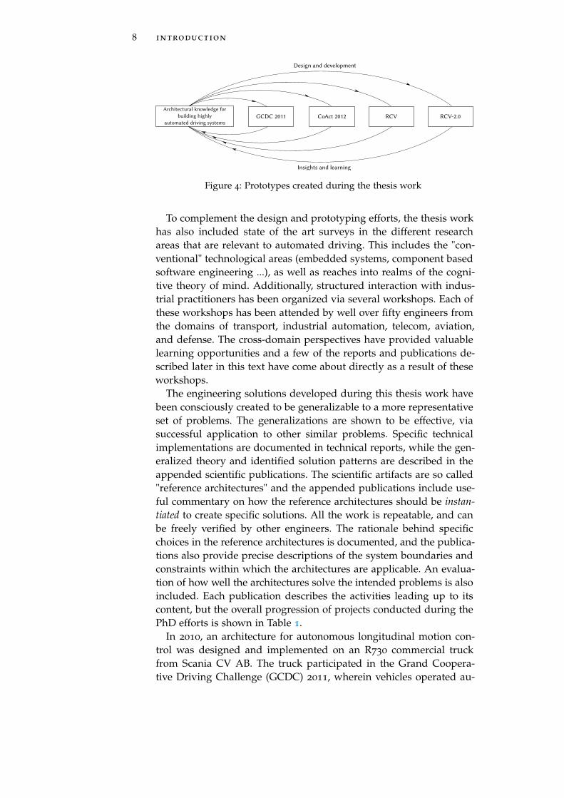
The research conducted during this thesis closely aligns with anestablished research methodology known as engineering design [6].This is one of the methodologies that is especially applicable to en-gineering, and acknowledges the purpose of engineering as creatingsufficient solutions to particular needs. The principal thrust of themethodology is that research is an activity to create new knowledge,and using engineering design to create particular solutions results innew situated knowledge. The situated knowledge is specific to the cir-cumstance, choice of technology, and the system architecture selectedand provides "proof by construction" that the design idea is valid andeffective [7]. The activity of design integrates fragments of existingknowledge to achieve a useful outcome. This includes, in the con-text of engineering design methodology, the application of scientificcriteria like repeatability, reproduceability, separation of own versusothers’ contributions, along with a sound theoretical understandingof why the developed solutions work3. Such a design activity usuallyalso involves advances beyond the state of art/practice. Furthermore,if discussions on potential generalization and validity are included,the overall result is a theory which links product requirements withthe solution developed, and a method for developing the solution [6].Following this methodology, four prototypes were created as shownin Figure 4. The design and implementation of each prototype yieldedvaluable insights which were used to improve the design and imple-mentation of the next prototype.
3 The understanding of why a solution works in a certain way is a key differencebetween engineering design and merely building something that works.
8 introduction
Figure 4: Prototypes created during the thesis work
To complement the design and prototyping efforts, the thesis workhas also included state of the art surveys in the different researchareas that are relevant to automated driving. This includes the "con-ventional" technological areas (embedded systems, component basedsoftware engineering ...), as well as reaches into realms of the cogni-tive theory of mind. Additionally, structured interaction with indus-trial practitioners has been organized via several workshops. Each ofthese workshops has been attended by well over fifty engineers fromthe domains of transport, industrial automation, telecom, aviation,and defense. The cross-domain perspectives have provided valuablelearning opportunities and a few of the reports and publications de-scribed later in this text have come about directly as a result of theseworkshops.
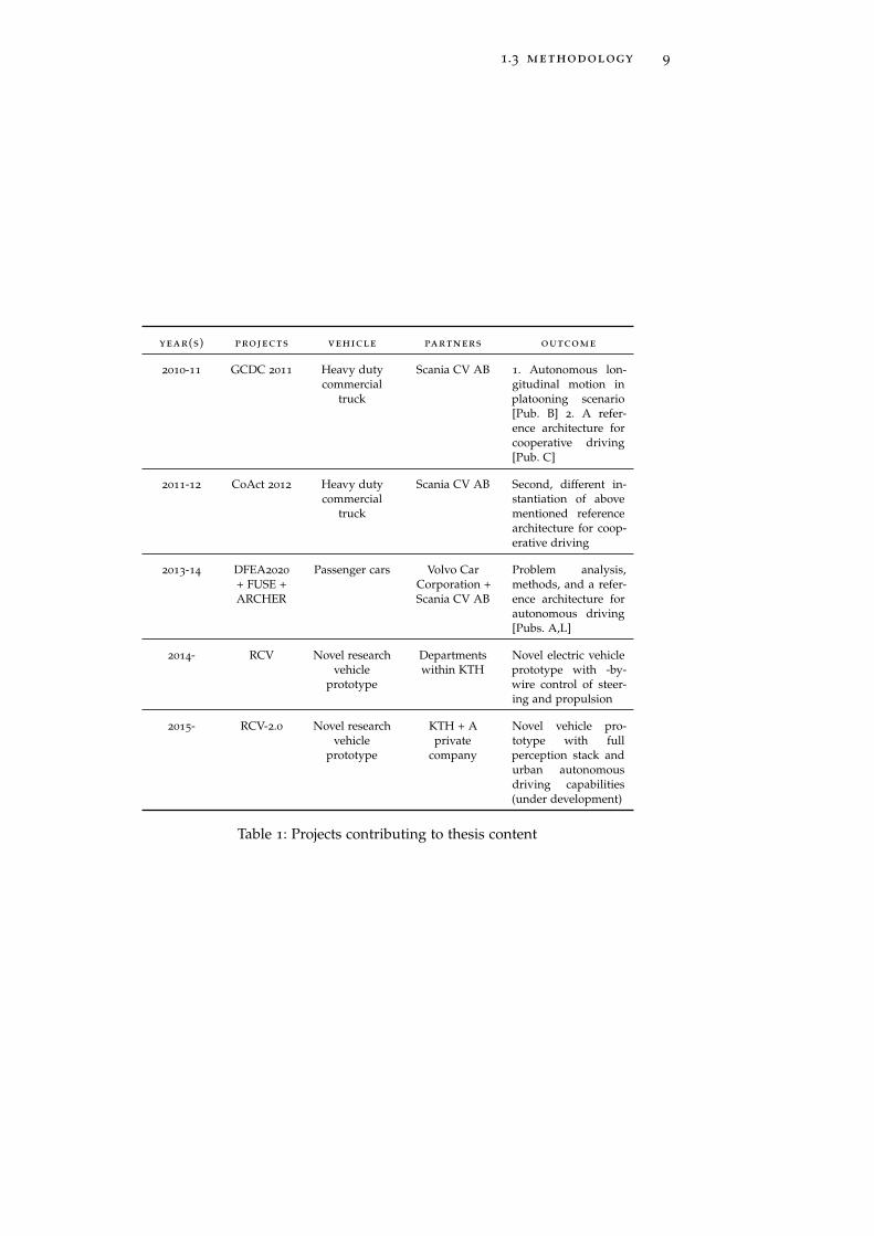
The engineering solutions developed during this thesis work havebeen consciously created to be generalizable to a more representativeset of problems. The generalizations are shown to be effective, viasuccessful application to other similar problems. Specific technicalimplementations are documented in technical reports, while the gen-eralized theory and identified solution patterns are described in theappended scientific publications. The scientific artifacts are so called"reference architectures" and the appended publications include use-ful commentary on how the reference architectures should be instan-tiated to create specific solutions. All the work is repeatable, and canbe freely verified by other engineers. The rationale behind specificchoices in the reference architectures is documented, and the publica-tions also provide precise descriptions of the system boundaries andconstraints within which the architectures are applicable. An evalua-tion of how well the architectures solve the intended problems is alsoincluded. Each publication describes the activities leading up to itscontent, but the overall progression of projects conducted during thePhD efforts is shown in Table 1.
In 2010, an architecture for autonomous longitudinal motion con-trol was designed and implemented on an R730 commercial truckfrom Scania CV AB. The truck participated in the Grand Coopera-tive Driving Challenge (GCDC) 2011, wherein vehicles operated au-
1.3 methodology 9
year(s) projects vehicle partners outcome
2010-11 GCDC 2011 Heavy dutycommercial
truck
Scania CV AB 1. Autonomous lon-gitudinal motion inplatooning scenario[Pub. B] 2. A refer-ence architecture forcooperative driving[Pub. C]
2011-12 CoAct 2012 Heavy dutycommercial
truck
Scania CV AB Second, different in-stantiation of abovementioned referencearchitecture for coop-erative driving
2013-14 DFEA2020
+ FUSE +ARCHER
Passenger cars Volvo CarCorporation +Scania CV AB
Problem analysis,methods, and a refer-ence architecture forautonomous driving[Pubs. A,L]
2014- RCV Novel researchvehicle
prototype
Departmentswithin KTH
Novel electric vehicleprototype with -by-wire control of steer-ing and propulsion
2015- RCV-2.0 Novel researchvehicle
prototype
KTH + Aprivate
company
Novel vehicle pro-totype with fullperception stack andurban autonomousdriving capabilities(under development)
Table 1: Projects contributing to thesis content

10 introduction
tonomously on a public highway in a platooning scenario, with con-stant wireless communication between participating vehicles and theenvironment. The architecture was refined and re-applied a year later,on a different truck (an R430 model), for the CoAct 2012 project. Thisproject also involved a platooning scenario similar to the GCDC 2011
event, but it included more demanding operational situations likesplitting and merging lanes, and overtaking. The accumulated archi-tecture underwent further evaluation and analysis in the course ofthree different projects with various industrial partners, includinga potential application to passenger cars. One of these projects wasDFEA2020 — a large Swedish consortium project aimed at develop-ment of green, safe, and connected vehicles. Another project is FUSE— also a Swedish project, with a tighter focus on functional safety andarchitectures for autonomous driving. The third project is ARCHER— which investigates safety, reference architectures, and testing andverification techniques applicable to commercial trucks. The FUSEand ARCHER projects are still in progress. Starting from 2014, the ar-chitecture was then applied to a novel research concept vehicle (RCV)at KTH, with a view to endow it with autonomous driving capabil-ities. The RCV has an all-electric, drive-by-wire powertrain with apropulsion motor embedded inside each wheel, and active steeringand camber control of all four wheels. Control of these componentsis included in a vehicle platform abstraction, which can receive ma-neuvering commands from a perception and planning layer. This wasused to demonstrate basic self-parking capabilities with the aid ofultrasonic sensors. The architecture was then adapted to a secondvariant of the RCV (RCV-2.0), where it serves as the foundation forautonomous urban driving capabilities in situations where a humandriver is not expected to be available (or capable) of taking over vehi-cle control.
1.4 hypothesis and research question
The engineering design research methodology described previouslyin Section 1.3 often deviates from a more traditional scientific researchprocess, with respect to how hypotheses are constructed. This is be-cause the traditional scientific research process consists of contemplat-ing on observations, formulating a hypothesis, making predictionsbased on the hypothesis, conducting experiments and gathering data,investigating the success of the hypothetical predictions, and declar-ing the hypothesis as valid under specific conditions. In contrast, thequestion, "What hypothesis fits the observed facts?" may justifiablynever be raised prior to the start of an engineering project. However,when differentiating between engineering and engineering design re-search, it is worth indulging this question post hoc in some form orthe other because, as mentioned in [16], presenting a rational process

1.4 hypothesis and research question 11
has the benefit of making the product (research) and design flow un-derstandable, maintainable, and reusable.
So how can a hypothesis be constructed for engineering design re-search? Well, it can be trivially asserted that engineering answers thehypothesis that it is possible to build a solution to the particular need.To improve upon the hypothesis, we can look at the implicit assump-tion in creating a particular engineering solution. The hypothesis canthen be generically rephrased as, "If the system is built «this way» thenit might fulfill its intended purpose. It may even work in more gener-alized cases, or could be more easily modified for those cases." Thisis better, but still generic. Applying this to the particular engineeringproblems considered in this thesis, the resulting (implicit) hypothesisthat underlies the thesis research can be stated as
hypothesis : A reference architecture for highly automateddriving exists, which is general enough to be repeatedly instan-tiated to provide sufficient solutions for a variety of automateddriving tasks in a variety of scenarios. Such a reference architec-ture will contain solution patterns and other value additions tohelp architects build apposite solutions for automated driving,especially with regards to performance and safety.
The above hypothesis leads to several questions like
• What are the requirements, principles, and patterns for architec-tures of highly automated driving systems?
• What are idealized architectures for distributed, embedded sys-tems that are expressly designed for high levels of automation?
• How does the potential absence of a human driver affect thearchitecture and associated safety analysis techniques?
• What are the technologies and development processes to imple-ment highly automated driving systems?
• What is the impact of high levels of automation on testing, ver-ification and validation methods?
Answers to these questions can be aggregated within reference ar-chitectures. The reference architectures need to be expressed at a levelof abstraction where they contain sufficient information to providebreadth and depth of solutions i.e. they are non-trivial, but at thesame time, are generic enough to be useful for more than one specificuse case. Therefore, the overarching research question investigated bythis thesis is
12 introduction
research question : What is a suitable reference architec-ture for highly automated driving?
• What are the main obstacles to high levels of automation?
• What are the principal architectural components and theirkey interactions?
• How should the architecture be organized, and howshould the components be distributed across the architec-ture?
• What are the key decisions, and the range of choices avail-able in making those decisions?
• What is a suitable methododolgy to design and instantiatethe architecture?
To answer the research question, it is crucial to have strong and re-curring hands-on experience in repeatedly designing and implement-ing different instances of highly automated driving systems. This hasindeed been one of the highlights of this thesis work, as described inSection 1.3.
1.5 overview of contributions
The thesis contributions can be organized into four categories: (i) Sci-entific theories (ii) Engineering (iii) State of the Art and Industrialchallenges and (iv) Education. Figure 5 shows the category for eachpublication. The main scientific contribution of this thesis is a set offunctional reference architectures for highly automated driving.
This section provides a quick overview of the contributions madeby the appended publications. Later, Chapter 2 provides an executivesummary and a reading guide through the main scientific results.
publication a : A key aim of this thesis is to create technical so-lutions for highly automated driving which can be adopted by prac-ticing engineers in the industry. Therefore, it is essential to gain anunderstanding of the obstacles to implementing such systems, froman industrial perspective. Some of the main obstacles are reported inthis publication, which resulted from structured interaction (and sub-sequent analysis) with about 65 practicing engineers at a workshopon autonomous systems organized at KTH.
publication b : The technical development of the cooperative driv-ing architecture used in the GCDC 2011 event is reported in this pub-lication. It covers architecture, communication, state estimation andcontrol.

1.5 overview of contributions 13
Figure 5: Categories of thesis contributions
publication c : This publication develops upon and generalizesthe architectural solution reported in publication B, resulting in afunctional reference architecture for cooperative driving.
publication d : This publication describes a functional referencearchitecture whose scope goes beyond cooperative driving towardshighly automated driving where human drivers may be absent.
publication e : This is a book chapter, summarizing a few keytakeaways in functional architecture, model based systems engineer-ing, and implementation technologies for autonomous driving. It alsorelates the shorter term technical developments of autonomous driv-ing systems with longer term perspectives from the theory of mindand associated cognitive sciences.
These five publications thus report on a continuous generalizationof automated driving architectures, with progressively wider applica-tion scope and validation.
publication f : This is an exploration into safety criticality andreliability aspects of architecting, and presents a functional architec-ture for a braking system that can be applied to autonomous, com-mercial, heavy trucks.
14 introduction
publication g : This is an early state of the art and literature sur-vey of the research areas contributing to the creation of automateddriving systems. It covers automotive E/E architectures, intelligentcontrol and robotics architectures, and general embedded systemsand software development. A synthetic discussion highlighting differ-ences between automotive and other domains is also included. Morefocused, topic specific state of art sections are also provided in publi-cations B, C and D.
During the course of the thesis work, especially during the inten-sive hands-on prototyping phases, it became clear that a specific setof technical skills is needed by engineers developing such systems. Asummary of these skills, along with how they can be incorporatedinto traditional embedded systems education, including sets of exer-cises, is provided in publications h-i. Interim (but peer reviewed)scientific results that contribute to the the main publications men-tioned above are presented in publications j-l. Many of the specifictechnology choices and other details used for practical implementa-tions are described in publication m.
1.6 impact
It is expected that the reference architectures and their descriptionspublished during this thesis work will be one of the starting pointswhen initiating a new architecture for highly automated driving. Asof October 2015, the early publications B and C have been cited 20
and 12 times respectively, according to Google Scholar. PublicationD is an invited paper based on an extension of publication L, whichwas considered to be among the best papers published at the venue.Publication E is an invited book chapter, presumably an acknowledge-ment of the contributions already made. Publication I is an extendedjournal paper based on publication H.
The engineering implementations of the autonomous truck archi-tectures used for the GCDC 2011 and CoAct 2012 are likely to be thebasis for the architectures used in the upcoming GCDC 2016 chal-lenge. The engineering implementations of the autonomous architec-ture for the research concept vehicle will be used to further develop acommercial product by a private company. It will also be the basis forupcoming autonomous driving capabilities of the prototype at KTH.
The following outcomes came about as a result of work done dur-ing the thesis, which are also an indirect indicator of its impact
• 3+1 journal papers, 1 book chapter, 1 conference paper, 3+1
workshop papers, 2 technical reports, 1 licentiate thesis
• 4 significant vehicle prototypes created

1.6 impact 15
• The KTH team finished fourth in the Grand Cooperative Driv-ing Challenge, The Netherlands, 2011
• A follow-up 3 year project named ARCHER, driven by ScaniaCV AB, funded by VINNOVA and engaging 3 PhD candidates
• 3 invited talks to large industrial conferences on autonomousdriving: Elektronik i Fordon (2012)/Sweden, Automotive Tech.AD(2015)/Berlin, and Automotive Tech.AD (2015)/Detroit
• 3 large workshops on autonomous systems and safety conductedat KTH, with participation of 50+ industrial researchers andpractitioners
• Invited member of Swedish delegation, to represent autonomoussystems research in Sweden, as part of Swedish-Brazilian gov-ernmental cooperation on research and technology, São Paulo,Brazil 2014
• Invited lectures on systems engineering and systems prototyp-ing at 2 European summer schools on Cyber-Physical Systems(Trento, Italy 2014 and Stockholm, Sweden 2015)
• 2 private companies founded in Sweden. Significant technologytransfer made to an autonomous driving related company in"Silicon Valley", California, USA
• 14 Master thesis students supervised
• Laboratory exercises for 3 courses developed for Embedded Sys-tems education


2R E A D I N G G U I D E A N D C O N T R I B U T I O N S
"A method of solution isperfect if we can foresee fromthe start, and even prove, thatfollowing that method weshall attain our aim."
— Gottfried Wilhelm vonLeibniz
This chapter provides a reading guide to the appended papers, aswell as an executive summary of their main content.
A quick word on notation: [A] means publication A. [A.2] meansSection 2 of publication A. [B.3.1] means Section 3.1 of publication B,and so on.
2.1 reading guide — publications
Each appended publication is complete in itself, and therefore can beread independently of the others.
• For a thorough reading, it is recommended to read the [A,B,C,D]in the order in which they are appended. This way, the readerwill first gain an understanding of the main obstacles to auton-omy, as seen from an industrial perspective [A]. This is followedby a description of the specific solution, including architecture,used during the Grand Cooperative Driving Challenge, 2011 [B].A generalization of the architectural solution in the form of a ref-erence architecture for cooperative driving is given in [C]. A fur-ther development into an architecture for general autonomousdriving is given in [D].
• If there is time to read only one publication, that should be [E].It presents the main concepts from [D] and also adds other non-architectural perspectives.
• [F] is specific to a braking system for heavy trucks and is notgeneralized to the overall vehicle architecture level. Therefore,it is recommended reading for those interested in this specificarea.
• Those interested in technological detail related to a specific in-stantiation of concepts in [B,C] should look up [M]
17

18 reading guide and contributions
2.2 frame of reference
This section briefly explains the relevance of key research areas con-tributing to autonomous driving. This is then followed by a concisereading guide to the various state of the art surveys included in thethesis work.
The systems architecture for automated driving needs to considerthe characteristics of a multitude of domains with regards to techni-cal requirements, the kind of software and other tools utilized, devel-opment processes, and even the typical ways in which the domainpractitioners think. It is quite rare that the statement, "Oh that.. yeah,that has no architectural impact whatsoever." can be made regardingany stakeholder concern.
Figure 6: Frame of reference for automated driving architectures
Figure 6 shows just a few of the research areas (and sub-areas) thatcontribute to architectures for highly automated driving. The areas tothe left of the vertical line are the more "fundamental" functional andtechnical areas, while those to the right of the vertical line apply moreto the cross-cutting aspects of the system and its development. Thearchitecture serves as the unifying framework and therefore a compe-tent systems architect needs to have more than a passing familiaritywith each domain.
Automotive development is of course the foundation which therest of automated driving is built upon. This is because, regardlessof what systems exist to perceive the environment and make motiondecisions, there always needs to be an underlying vehicle platformresponsible for executing the desired vehicle motion. The successful

2.2 frame of reference 19
development of core motion systems like steering, propulsion, andbraking requires significant know-how from the automotive domain.
Functions for environmental perception, localization, and path plan-ning are based on techniques evolved in the Robotics and ArtificialIntelligence areas. This especially applies to the topics of computer vi-sion, extraction of features from sensor data, classification and learn-ing of objects, and planning collision-free trajectories in realtime. As-sociated algorithms are often probabilistic and may not guaranteeresults within a given time window. This has an impact on the ar-chitecture and analyses related to safety and certification, which areconventionally targeted towards heavily deterministic behavior. Sim-ilarly, the computation silicon and typical technological platformsused for robotics and AI research differ from the conventional au-tomotive ECU hardware and software, in terms of available compu-tational capacity and software tools used. This impacts the technicalarchitecture of the automated driving system.
The ever increasing usage of sophisticated electronic control for ba-sic functions like braking, as well as relatively higher level trajectorytracking requires strong contributions from the control engineeringdomain. There are a large number of modes and states of various sys-tems and their subsystems, the hierarchical and distributed controlstructures need to respond with correct and safe behavior if and whenfaults occur, signal uncertainty increases, degraded system modes areentered etc.
Most automated driving functionality is realized through software,and therefore software engineering plays an important role in the sys-tem design and development. From the design perspective, topics re-lated to middleware, platform abstraction, and component based soft-ware engineering are becoming increasingly relevant, as evidenced bythe growing adoption of AUTOSAR. Even for the prototyping codeused in the "higher level" functionality related to environmental per-ception and decision making, technologies like the Robot OperatingSystem (ROS) are commonly utilized, which facilitate reusable soft-ware components and inter-component communication. On the de-velopment side, topics like agile development and continuous integra-tion are important, because of requirements of faster time-to-market,and delivery of updates and bug fixes to deployed software code.
The inclusion of safety and systems engineering hopefully needsno justification. However, Model Based System Engineering (MBSE)is an important, and sometimes overlooked, part of systems archi-tecting. In MBSE, the different artifacts generated during the systemsdevelopment process are represented in the form of models, many ofwhich are inter-linked. The architectures can be modeled, analyzed,and successively enriched and it may be possible to generate work-ing system implementations purely via model transformation meth-ods. This is sometimes the case for purely control related tasks, where

20 reading guide and contributions
topic publication
Automotive EE architecture G.2
Robotics and intelligent control G.3
General Embedded Systems G.4
Discussion: Automotive vs. other domains G.5
Vehicle platooning and its benefits B.1.a
Cooperative driving C.1.3
Architectures for autonomous driving D.4.3
MBSE methods and tools E.1.7, E.1.7
Machine consciousness E.1.4
Table 2: State of the art surveys
the tasks can be modeled and simulated in a tool like Simulink, andthe models can be executed using rapid control prototyping toolslike the dSpace MicroAutoBox. The models may be annotated withrequirements like safety, and specific system properties can be ana-lyzed within Simulink itself, or via the use of add-on tools. Often,specific tools work only with a given representation, and so MBSEhas the concept of "round trip" flows, wherein (a part of) the systemcan be modeled in one tool, the model undergoes transformation toanother representation which is analyzed and/or enriched via someother tool, and then subsequently transformed back to the originalrepresentation. When such models and tools are also used for gen-erating implementation code, it can impose very strong constraintson the implementation technologies. This has a direct bearing on thetechnical architecture.
The architectural decisions need to consider not just the technicalcharacteristics of the various domains involved, but also the mind-sets of experts within these domains. It is sometimes the case thatindividuals with deep expertise with one set of tools and conceptsin a domain are unable to appreciate why experts in other domainsprefer a different set of tools.
In addition to the areas shown in Figure 6, an architect also needs tokeep regulatory and certification concerns in mind. MBSE techniquescan facilitate dealing with such concerns, by generating documen-tation trails, proving safety properties, and analyzing the impact ofsystem changes.
A mapping of the state of the art surveys conducted during the the-sis work and the publications which contain them is shown in Table2. The general state of the art on the technological areas contributingto autonomous driving is provided in [G]. It considers autonomousdriving as the intersection of the three main areas: (i) Automotive

2.3 executive summary of contributions 21
(ii) Robotics and Intelligent control and (iii) General Embedded Sys-tems. The individual coverage of each of these three areas [G.2, G.3,G.4] is followed by a brief discussion highlighting their relevance andimportance to autonomous driving. This is followed by a longer dis-cussion [G.5] comparing architectural considerations for automobilesand robotics, since autonomy in the former is heavily influenced bythe latter. This publication was prepared mid-way during the the-sis work. The areas considered remain key to technical developmentof autonomous driving functionality. However, during latter parts ofthe thesis work, it became clear that complementary results are alsoneeded from other areas. These are covered in subsequent publica-tions, where relevant to the context.
The concept of vehicle platooning and its benefits are presented[B.1.a]. This includes references to the performance and stability ofplatooning vehicles, fuel saving potential, and the effects on trafficthroughput. Also mentioned are some of the European Union projectscontributing to these areas. A more generalized survey of cooperativedriving is given in [C.1.3]. This survey covers three areas (i) Impact ofintelligent cooperative driving on traffic flow (ii) Selected results fromindividual technological areas of automatic control, wireless commu-nications, and smart transport infrastructures and (iii) Systems inte-gration efforts relevant for whole systems.
Three representative architectures for autonomous driving are men-tioned in [D.4.3], for the purpose of comparison with a proposed ref-erence architecture. The architectures are for Stanford’s Junior vehiclewhich participated in the 2007 DARPA Urban Driving Challenge, theHAVE-IT project architecture, and the architecture of the MercedesBenz S-class car, Bertha. The architectures were selected because theyare representative of the evolution in autonomous driving architec-tures.
Finally, a brief overview of systems engineering methodologies andtools is provided in [E.1.6] and [E.1.7], while a [E.1.4] presents anoverview of concepts and relevant takeaways from the area of com-putational self-awareness and machine consciousness.
2.3 executive summary of contributions
This section summarizes the key content and takeaways from the ap-pended publications. It is intended to be a self-contained write up forthose readers who may not want to read all the publications. Notethat for the sake of convenience, citations present in the actual publi-cations are removed from the summary.
22 reading guide and contributions
2.3.1 Architecture challenges for intelligent autonomous machines ([A])
[A] identifies the main bottlenecks for autonomous systems develop-ment, from an industrial perspective. The identified bottlenecks arenot exclusive for autonomous systems, but they are especially rele-vant to this category1. The main bottlenecks are
constructing and maintaining the world model Intelligentautonomous systems need a model of their internal and ex-ternal environments (worlds) to correctly reason about actionchoices and make decisions. At all times, the model needs to re-flect the real environment, typically via strong statistical corre-lations. There are several architectural issues related to the con-struction, implementation, and maintenance of a world model.Subsystems may require partial world models containing onlythe information necessary for the subsystem operation. The sameinformation may be needed by several subsystems, but in differ-ing representations. Simultaneously, it may be desirable to havea global, common world model to prevent unnecessary, repli-cated model building activities within individual subsystemsand to have a single source of data. But the subsystems may re-quire the model information with differing Quality of Service(QoS) requirements. Some subsystems may require historicalinformation. Should the subsystem maintain history itself orshould it be part of a common global world model? Should thepartial world models within individual subsystem be gatheredtogether to form a common global model? Or should relevantparts of the global world model be "projected" into individualsubsystems? Should a global world model be implemented in adistributed, redundant way? What about security and accesscontrol to the model information? Who are the readers, whoare the writers, how to manage simultaneous conflicting writes— these are all questions relevant to the system architecture.
user interaction An autonomous system must necessarily reducethe user engagement required for system operation. If the re-quired user engagement is maintained or increased (with re-spect to frequency, level of control, scope, etc.), autonomy pro-vides no immediate benefit. At the same time, the system needsto conduct its operations with maximum transparency, so thatthe user can be aware of the operational context and system be-havior. Unfortunately, it is not always clear what ’transparency’implies, nor do established norms exist to achieve it. Automa-
1 This is actually a recurring theme for many research areas. There are few resultsthat are solely and exclusively for autonomous systems alone. However, given thecomplexity and safety critical nature of the autonomous systems, some results havea magnified importance in context.

2.3 executive summary of contributions 23
tion and autonomy, though intended to enhance human capabil-ities, often degrade them. Worse still, lack of consensus on userinteraction leads to functionally similar, yet subtly different au-tonomous systems. This makes it problematic to rely on pastexperience when human operators migrate between similar sys-tems. Relying on faulty automation might easily be framed asover-reliance and misuse, while relying on correct automationthat still allows for mistakes might be framed as under-relianceor disuse. From the perspective of autonomous systems, it there-fore becomes relevant to explore flexible architectures that allowfor different user interaction paradigms while maintaining max-imum transparency and a meaningful exposure of error han-dling strategies such as graceful degradation.
complexity and feature interaction Federated and integratedarchitectures are meant to decentralize the logical architectureand allow for treating different functionality in isolation. How-ever, autonomy seems to be pushing in the other direction, re-quiring an increased communication between different subsys-tems. The result is an increased architectural complexity, wherethe architecture is required to simultaneously isolate and bringtogether different parts of the system. This, coupled with theincreasing number of (often conflicting) goals within an au-tonomous system, significantly raises the cognitive complexity ofthe system. Increasing complexity has a direct and negative im-pact on test case coverage, verification and validation of the sys-tem. One of the potential consequences of complexity is featureinteraction. A feature interaction is said to occur when the op-eration of a subsystem/feature interferes with the operation ofanother subsystem/feature leading to unexpected and undesir-able system level behavior, for example, simultaneous actuationof the brake and throttle during driving. From an architecturalperspective, feature interaction can be addressed by two com-plementary approaches. The first approach is ’correctness byconstruction’ which refers to the principles and mechanisms ofcomposing systems out of subsystems in a way that there are nounexpected side effects or emergent behavior. The complement-ing approach is to formally represent both the architecture anda feature interaction and use model checking and verificationmethods to search for the feature interaction in the architecture.Once found, the interaction can be eliminated by a variety ofproblem specific approaches. Both the approaches above seekto detect and eliminate feature interactions during the designphase. However, all feature interactions may not be detected oreliminated and therefore intelligent autonomous systems needmechanisms to resolve feature interactions during system oper-ation (a.k.a ’runtime’).
24 reading guide and contributions
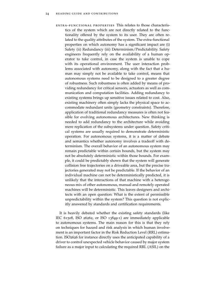
extra-functional properties This relates to those characteris-tics of the system which are not directly related to the func-tionality offered by the system to its user. They are often re-lated to the quality attributes of the system. The extra-functionalproperties on which autonomy has a significant impact are (i)Safety (ii) Redundancy (iii) Determinism/Predictability. Safetyengineers frequently rely on the availability of a human op-erator to take control, in case the system is unable to copewith its operational environment. The user interaction prob-lems associated with autonomy, along with the fact that a hu-man may simply not be available to take control, means thatautonomous systems need to be designed to a greater degreeof robustness. Such robustness is often added by means of pro-viding redundancy for critical sensors, actuators as well as com-munication and computation facilities. Adding redundancy toexisting systems brings up sensitive issues related to cost. Also,existing machinery often simply lacks the physical space to ac-commodate redundant units (geometry constraints). Therefore,application of traditional redundancy measures is often not fea-sible for evolving autonomous architectures. New thinking isneeded to add redundancy to the architecture while avoidingmere replication of the subsystems under question. Safety criti-cal systems are usually required to demonstrate deterministicoperation. For autonomous systems, it is a matter of debateand semantics whether autonomy involves a tradeoff with de-terminism. The overall behavior of an autonomous system mayremain predictable within certain bounds, but the system maynot be absolutely deterministic within those bounds. For exam-ple, it could be predictably shown that the system will generatecollision free trajectories on a driveable area, but the precise tra-jectories generated may not be predictable. If the behavior of anindividual machine can not be deterministically predicted, it isunlikely that the interactions of that machine with a heteroge-neous mix of other autonomous, manual and remotely operatedmachines will be deterministic. This leaves designers and archi-tects with an open question: What is the extent of permissibleunpredictability within the system? This question is not explic-itly answered by standards and certification requirements.
It is heavily debated whether the existing safety standards (likeIEC 61508, ISO 26262, or ISO 13849-1) are immediately applicableto autonomous systems. The main reason for this is that they relyon techniques for hazard and risk analysis in which human involve-ment is an important factor in the Risk Reduction Level (RRL) estima-tion. ISO2626 for instance directly uses the anticipated capability of adriver to control unexpected vehicle behavior caused by major systemfailure as a major input to calculating the required RRL (ASIL) on the

2.3 executive summary of contributions 25
system. This reasoning is not immediately applicable for autonomousand intelligent functions because of the lack of human involvement.However, one way by which a standard like ISO26262 can be appliedto autonomous driving, is to reduce the controllability to the worstcase value for a given hazard. This then leads to higher ASIL levelsfor the hazard under consideration.
2.3.2 Platooning and cooperative driving ([B] and [C])
This section covers the specific architecture used during the GrandCooperative Driving Challenge (GCDC) 2011 [B], and the subsequentgeneralization to a reference architecture for cooperative driving [C].The team that participated in the GCDC was named "Scoop" andhence, the architecture used during the GCDC is referred to as the"Scoop architecture" in [B].
The Scoop architecture comprises of a distinct set of sensors, com-putation hardware, software, and communication components installedon top of a factory standard truck. These additional components com-municate with the factory standard motion subsystems in the truck,such as the engine, brakes, and the transmission. The main require-ments that the architecture fulfilled were
• Separation of the functionality into self-contained logical units,which could be designed, developed, and tested independentlyof each other by different teams
• Enabling of run-time reconfiguration of inter-component com-munication (change sources/sinks), in order to generate differ-ent system behaviors. For example, it should be possible toroute an existing data-flow between components A → B → Cto A → C, in case component B malfunctions.
• Permitting different algorithms to be swapped in and out of thedifferent architectural components
• Enabling diagnostics and self-monitoring services for each ar-chitectural component
• Allowing changes to the running system. Changes include re-configuration of component properties and calibration parame-ters within executing components
• Being minimally intrusive in the existing vehicle architecture
The top level logical functions in the architecture are shown in Fig-ure 7. They include Information gathering, Estimation, Control, Informa-tion broadcast, and Supervision. A description of each function can befound in [B.II.B.2]. The system was implemented using two distinct

26 reading guide and contributions
Figure 7: Scoop architecture: Logical functions
computers (i) A custom computer designed using off-the-shelf com-ponents with no moving parts and (ii) A re-purposed ECU from Sca-nia. This hardware view is shown in Figure 8 and further describedin [B.II.B.3]. The custom computer was based on a dual-core Intelx86 processor architecture (Atom) with a GNU/Linux operating sys-tem. The OROCOS realtime middleware was used for constructingsoftware components on this computer. The Scania ECU executed en-tire Simulink models "at the press of a button" using code generationand a proprietary toolchain. The two computers communicated via adedicated CAN bus, and each computer was additionally connectedto a CAN bus in the truck. The GPS and wireless communicationhardware was connected to the custom computer.
The ORCOCS middleware enables creation of components and spec-ification of the components’ characteristics such as periodicity of ex-ecution, number of input/output ports, datatypes flowing throughports, etc. It also has native support for buffered and unbufferedinter-component communication, as well as for raising and reactingto asynchronous events. Various OROCOS components were created,with close correspondence to the logical functions depicted in Figure7. The mappings between these software components and the logicalfunctions are shown in the implementation view depicted in Figure9, where the arrows indicate an "implements" relationship. So for ex-ample, the ’Wireless’ component in the software layer implements ’In-formation gathering’ and ’Information broadcast’ from the functionallayer. This is further described in [B.II.B.4]
The Scoop architecture was very successful according to a numberof evaluation criteria, the key points of which were

2.3 executive summary of contributions 27
Figure 8: Scoop architecture: Hardware view
Figure 9: Scoop architecture: Implementation view

28 reading guide and contributions
• The implementation worked at the technical level. No unexpectedcrashes, segmentation faults, mysterious behavior. The systemstartup and shutdown was clean, with state being saved, gooddatalogging and easy possibilities for runtime system calibra-tion.
• The architecture mostly stayed in the background, avoiding in-trusion in the function developers’ mindspace. They could gettheir job done without thinking too much about the architectureor using ’quick-and-dirty’ hacks to bypass architectural limita-tions.
• The architecture scored well on aspects of robustness, extensi-bility, and safety. Unexpected inputs rarely caused the systemto get unstable, and behavior modifications were being madeto acknowledge changing competition rules up until the day ofthe event.
• The architecture guided thinking and showed possibilities, ratherthan constraining the options available to the developers
[B.II.B.5] discusses other topics related to the architecture, such ashow specific behavior emerges from the interaction between the ar-chitectural components.
Generalizing beyond the Scoop architecture, [C.2.1] describes char-acteristics of cooperative driving systems, classifying them in func-tional, extra-functional, and miscellaneous categories. The functionalcharacteristics note the distributed, hierarchical nature of the controltask, that requires constructing a world model from limited sensorinput (compared to the sensory inputs of a human driver). The extra-functional characteristics emphasize reliability and accuracy of data,as well as the mixture of safety critical and non-critical componentswithin the same platforms. As a precursor to the reference architec-ture, [C.2.1] briefly discusses the differences between software execu-tion environments in dedicated microcontrollers and general purposePC hardware, and the associated impact on the architecture.
A reference architecture for cooperative driving is introduced in[C.3], within the context of the ECU network found in existing vehicleE/E architectures. The services needed in a cooperative driving sys-tem are identified, and they include positioning, communication, ve-hicle interfaces, Human Machine Interface (HMI), among others. Thereference architecture shown in Figure 10 is then described. First, thekey properties common to all architectural elements are mentioned,followed by a more detailed description of the individual functionalelements.
[C.4] provides guidelines for instantiation of the reference archi-tecture. The guidelines cover the minimum data sets needed for aninstantiation to function as well as considerations for implementing

2.3 executive summary of contributions 29
Figure 10: A reference architecture for cooperative driving
each of the elements in the reference architecture. These considera-tions include computational capacity, execution environments, ven-dor solutions, and testing/calibration needs. [C.4.2.2] digs deeperinto communication mechanisms and covers bandwidth requirements,Quality of Service (QoS) concerns, and communication patterns suchas publish/subscribe.
[C.6.2.1] gives some examples of how the reference architectureworks by considering four different scenarios. These scenarios are(i) Controlling vehicle motion in a platoon (ii) Approaching a platoonfrom behind and joining in (iii) GPS signal loss and (iv) An exter-nal demand for imposition of radio silence is received. For each ofthese scenarios, it is described how the various architecture elementsinteract with each other, and which data flows between them. A com-parison of the reference architecture with the industry standard AU-TOSAR framework is made in [C.6.3], and with other autonomoussystem architectures in [C.6.4]. The comparisons show that the refer-ence architecture does not make radical departures from establishedprinciples of autonomous system architectures, but there are novelaspects related to how it adapts to existing vehicle architectures in aminimally invasive way, by becoming another "node on a bus".
The reference architecture was instantiated a second time duringthe CoAct 2012 project. In this instantiation, the Scania ECU shownin Figure 8 was replaced by a SpeedGoat xPC Target controller, whichuses a rather different technological implementation stack, but is func-tionally identical in the sense that it executes a Simulink model "at thepush of a button". The mapping shown in Figure 9 was also changed.Specifically, the Estimator function was moved to the SpeedGoat unit,along with the GPS Manager. Of course, the GPS hardware was thenconnected to the SpeedGoat. These changes were made in view of thefact that the CoAct project team did not have as many competent C++

30 reading guide and contributions
Figure 11: Main functional components for autonomous driving
programmers as the GCDC/Scoop team. Therefore, it was consideredeasier to design most of the functionality in Simulink, which requiresless programming skills. While it would still be possible to generateC++ code from Simulink and execute it on the custom computer, itwas far easier to do so on the SpeedGoat, because of all the instru-mentation and tools provided by the MathWorks for their xPC prod-uct. A consequence of these changes was an increase in the requiredcommunication bandwidth between the custom computer and theSpeedGoat, compared to the Scoop architecture. This was addressedby changing the dedicated link between the computers from a CANbus to 100Mbit/s Ethernet using the User Datagram Protocol (UDP).This second instantiation also incorporated algorithms that providedadditional functionality related to lateral maneuvers and overtakingin platoons. This instantiation was also deemed to be entirely satis-factory.
2.3.3 Autonomous driving ([D] and [E])
A three layer functional reference architecture for autonomous driv-ing is described in [D]. First, the functional components are described,followed by reasoning on how the components can be distributedacross the architectural layers. The architecture description itself con-sists of identifying the principal stakeholder concerns, the connec-tions among the components and a comparison with similar architec-tures to highlight similarities and differences.
The main functional components are shown in Figure 11 and de-scribed in [D.2]. The components are grouped into three categoriesrelating to (i) Perception (ii) Decision and control and (iii) Vehicleplatform manipulation. The Perception components include sensing,fusion, localization, semantic understanding and the world model.These components are responsible for gathering data about the im-mediate operational environment, and interpreting this data to forma consistent view of the world. The world view includes knowingthe position of the vehicle with respect to a map, static road features

2.3 executive summary of contributions 31
(lane markings, guard rails etc.), the location, size, and motion ofmoving objects and their classification (car, truck, bicycle etc.) Thedecision and control components are responsible for generating adesired, collision-free motion trajectory among obstacles, keeping inmind concerns of energy management, vehicle state with respect tofaults and errors, as well as requirements of good road usage andlegal limits. The generated trajectory is usually in ’world coordinatespace’ i.e. it defines how the vehicle should move in the physicalworld with respect to the map coordinate system. The trajectory maybe represented as a set of accelerations and velocities which is passedon to the vehicle platform. The vehicle platform includes various actu-ation components responsible for actual vehicle motion (propulsion,braking, steering), and passive safety of the platform. These compo-nents generate the actuator specific commands that will realize thedesired trajectory.
This architecture is an evolution of the cooperative driving archi-tecture which is discussed in the previous section, and shown in Fig-ure 10. Components like the vehicle gateway, semantic understand-ing, and the world model have been retained. Other functions in thecooperative driving architecture, like localization and control havebeen expanded upon in the autonomous driving architecture. A no-table difference between these architectures is the role of the worldmodel in the overall data-flow. In the cooperative driving architec-ture, the world model is at the center, and it can not be bypassed.All data flows into and out of the world model, which becomes thecentral repository of all information in the system. This imposes highperformance and reliability requirements on the world model. Giventhe scope of cooperative driving, these were technically achievable,especially since the latency introduced by the world model was con-sidered to be acceptable for the application. This has not been thecase for the autonomous driving architecture, which sees consider-ably larger data throughput to/from the world model. Therefore,this architecture supports direct data transfer between various com-ponents, as well as via the world model. During instantiation, theextent to which the world model intervenes in the data flows canbe freely determined. This would range between two extremes: onewhere the world model only passively records data flowing betweenthe different components, and the other where all data flows throughthe world model, during the journey from producer to consumer.
The autonomous driving architecture is initially split up into twolayers2: the vehicle platform and a cognitive driving intelligence. [D.3]discusses how the functional components can be distributed acrossthese layers, by considering two extremes and their pros/cons. The
2 Later, a third layer related to teleoperation is added, but this layer is not directly re-sponsible for generating and executing motion requests during normal autonomousdriving

32 reading guide and contributions
recommended functionality distribution is based on achieving as cleana split as possible, between the driving intelligence and the vehicleplatform. This lowers the cognitive complexity of the architecture, aswell as reduces the potential for feature interaction and other undesir-able emergent behavior, for example by clearly delineating the tasksof trajectory generation and its execution. It also enables better reuseof the driving intelligence and the vehicle platform in other projects.Thus, the autonomous vehicle is really considered to be a close co-operation between two distinct autonomous entities, which are thevehicle platform and the cognitive driving intelligence. Of these, theformer is relatively less intelligent, and responsible for maintainingits own safety to the extent of not violating laws of physics and keep-ing the vehicle within its safe performance envelope, regardless of themotion requested. The latter is more intelligent and capable of takingdecisions under uncertainty and reasoning on its perception of theoperational situation. This split is not unlike that of a human being(the cognitive driving intelligence) riding a horse (which is arguablyautonomous, with significantly reduced intelligence compared to thehuman rider).
An architecture balances stakeholder concerns. Therefore, the archi-tecture description first identifies the main stakeholder concerns fora functional architecture. These concerns are grouped into two cate-gories: Business and Engineering. The business concerns relate to con-siderations of economics, upgrade paths from existing product archi-tectures, unified architectures for autonomous and non-autonomousproduct variants, and methods to reduce and accelerate testing, verifi-cation and validation. Business concerns also reflect regulatory, stan-dards, and certification aspects as well as the possibilities of post-sale modification to vehicle software. The engineering concerns relatemore to the functionality of the individual components, and the abil-ity to develop and test them independently. They cover the technolo-gies for virtualized and simulated vehicle testing and the constrainsand characteristics of the actual tools and technologies used to imple-ment the vehicle.
The proposed reference architecture is shown in Figure 12 and de-scribed in [D.4.2]. Some of the more interesting data links are de-scribed, such as that between the localization and sensor fusion, whichcan be used for modifying Bayesian priors3 of how the sensor datais characterized at specific geographical locations (e.g. tunnels). Theinterface between the cognitive driving intelligence and the vehicleplatform consists of at least two trajectories: one which takes the vehi-cle to its desired destination and the other which takes it to a safe(er)state via open-loop control, in case of a sudden and total failure of thecognitive driving intelligence layer. The reactive control is allocated to
3 The ’expected value’ of lidar inputs can be modified, for example, if it is known thata particular location always gives noisy returns.

2.3 executive summary of contributions 33
Figure 12: A functional reference architecture for autonomous driving
the vehicle platform, because in our experience, existing technical im-plementations of the perception and decision and control componentshave not been fast enough to always deal with unexpected events aspart of deliberative control. The presence of the tele-operation layeris also elaborated upon. This layer is chiefly used for gathering telem-atics data to assess vehicle performance, as well as to manually andremotely guide the vehicle in case it gets stuck in its decision makingprocesses.
A comparison of the proposed reference architecture with otherpublished architectures for (partially) autonomous driving is made in[D.4.3]. The compared architectures are for Junior, Stanford’s winningentry in the 2007 DARPA Urban Driving Challenge, the HAVE-ITproject’s architecture for advanced driver assistance systems, and theMercedes Benz S-class vehicle that completed a 103 mile autonomousdrive from Mannheim to Pforzheim in 2014. These architectures repre-sent a steady improvement of functionality and implementation overthe past decade, as well as involvement of academic, Tier 1 and OEMstakeholders. The comparison shows that explicit recognition of se-mantic understanding, world model and vehicle platform abstractioncomponents are unique to the proposed architecture.
The discussion in [D.5.2] looks at how the functional architecturecan be affected by the eventual technical architecture and the char-acteristics of technologies used in the domains of control engineer-

34 reading guide and contributions
Figure 13: Systems engineering model classes
ing, embedded systems programming, and computer science. This isdone by considering the most common tools used in these fields. It ishighlighted that the components of the vehicle platform are typicallyimplemented by control engineers and embedded systems program-mers, whereas the components of the cognitive driving intelligenceare implemented by computer scientists who use general purposecomputers during the prototyping phases, and presumably more ma-ture platforms as these systems get closer to series production.
2.3.4 Model based systems engineering ([E])
The complex and safety-critical nature of highly automated drivingsystems increases the need to use systematic systems engineering pro-cesses. A model based systems engineering process for autonomousdriving systems is outlined in [E.1.4]. The process consists of foursteps, each of which is associated with a variety of model classes. Themodel classes are depicted in Figure 13 and the steps are
1. Describing the system concept of operation
2. Creating a logical system architecture, independent of imple-mentation technologies
3. Mapping the logical system architecture to application softwarecomponents
4. Implementing the application software components on candi-date platforms
Associated with all the four modeling steps is a continuous refine-ment of requirements, test cases, safety viewpoints, and documenta-tion artifacts. Each step must introduce additional models represent-ing requirements and test cases relevant to that step. Requirementsmust be allocated to models that assure them, and both requirementsand test cases need to be assigned to unique members of the engineer-ing team. Safety considerations are usually incorporated by followingprocesses established by safety standards like ISO26262. This impliesthat additional models/views like functional safety architecture willbe introduced, along with their refinements to technical safety archi-tectures and associated redundancies and switching modes for ap-plication software and platform components. The number of models

2.3 executive summary of contributions 35
Figure 14: Partial view of modeling artifacts and allocation links
may grow and shrink at each step as the systems engineering processis iteratively applied during system development. Ultimately, the arti-facts ideally exist as a web of interconnected models at each step andacross the steps. Preserving the links between the models, and keep-ing the models up to date with the implementation is a significantchallenge. One way to do this is via increasing toolchain automation,but given the relative lack of production ready tools, it becomes theresponsibility of the architecting and systems engineering team toselect and minimize the number of models used to represent the sys-tem. This in turn, depends on a variety of technical and non-technicalfactors like the nature of the project and its maturity level, availabletools, the importance attached to systems engineering by project man-agement, the skills and qualifications of the people involved etc. Onerecommendation based on our experience is to always synchronizethe software and platform models with the actual technologies be-ing utilized in the project. These will change as the project movesthrough stages of proofs-of-concept, prototyping, to certifiable imple-mentations. The models need to be updated correspondingly.
Based on the four modeling steps, a partial view of modeling ar-tifacts and their allocation links is shown in Figure 14, where therightmost column describes some of the functionality provided bythe models. The dotted, curved arrows crossing the vertical layersrepresent allocation links. Thus arrows between the architecture rep-resentation and application software components show the mappingbetween logical architecture elements and particular application soft-ware components. For the sake of clarity, the continuous refinement

36 reading guide and contributions
and accumulation of requirements and tests are not shown in theFigure.
An overview of key technologies for modeling and implementingautonomous driving systems in given in [E.1.5].
2.3.5 The context of machine consciousness ([E])
When thinking about autonomous driving, it is very easy to get lostin practical minutiae of sensors, hardware, programming, modelingetc. However, staying entirely at this level can lead to "not seeing theforest due to all the trees". As the complexity of system architecturesrises, it is worth taking a step back and asking, "What is it that we arereally trying to do, and is this the right direction?"
The ultimate goal for autonomous driving is not just human-likedriving, but to go beyond human-like driving in order to overcomehuman limitations and appreciably increase road safety, traffic effi-ciency, and environmental benefits. To achieve this goal, and to in-teract and coexist with human environments, machines would needa level of consciousness that approaches human (admittedly undertightly constrained notions). This is because consciousness is instru-mental to reasoning, decision making, and problem solving capabili-ties in the face of uncertainty. Indeed, a variety of literature suggeststhat robots’ problem solving capacities would be enhanced by theability to introspect. This is also a recurring theme across disciplineslike computer Systems-on-Chip, programming languages, roboticsand even explorations for fault-tolerant on-board computing for roboticspace missions. Therefore, it is worthwhile to ask, "What is conscious-ness?" and "What would consciousness mean in the context of au-tonomous driving?". This topic is explored in [E.1.6].
From a strict engineering perspective, it is considered that ques-tions regarding the actual nature of consciousness are too vague ormysterious to answer. Indeed, as far back as the 1950s, researcherslike Alan Turing proposed a behaviorist alternative, wherein if a ma-chine can be considered intelligent (and presumably conscious) if itdisplays behavior that would be considered human-like, by other hu-mans. A loose application of this behaviorist concept to autonomousdriving could be: If a savvy human judge can consistently accept acomputer’s driving abilities as equivalent to those of a competent hu-man driver, then we would have some measure of the computer’sdriving capabilities. Indeed, on 4th May 2012, one of Google’s self-driving Prius vehicles was granted a "driving license" by the NevadaState Department of Motor Vehicles, after the vehicle successfullypassed driving tests similar to those administered to human drivers.
In a machine’s architecture, the awareness of the external world isusually explicitly represented in the internal world model of the ma-chine, by maintenance of data structures reflecting perception of the

2.3 executive summary of contributions 37
external world. From a philosophical point of view then, awarenessof the external world is "absorbed" by the machine’s internal states, towhich engineering attention must be devoted, in order to achieve pro-gressive results in machine consciousness. However, for meaningfulexploitation of any internal awareness, the machine needs to be awareof the awareness i.e. it needs to be self-aware. One approach to under-standing self-awareness is to understand how the human brain func-tions, and to mimic biological structures found therein. The strongestapproach to understanding human consciousness (and the only onerelevant to autonomous driving) is that of computationalism, which isthe theory that many relevant aspects of the human brain can be mod-eled as having a computational structure. This approach is the basisof the field of Artificial Intelligence (AI) which explores computationalmodels of problem solving. A synthetic summary of the principalpropositions of dominant researchers in the field is that "..conscious-ness is the property a computational system X has, if X models itself asexperiencing things.". Thus, central to the theory of computational con-sciousness is that introspection is mediated by models. Such modelsare explored in the research area of cognitive architectures, some ofwhich are mentioned in [E.1.6] along with pointers for further study.
[E.1.6] also discusses a critical review of cognitive architectures thatwere found in the literature. This review is in terms of applicationsto real world, safety critical systems and is made along four mainthemes of (i) Realtime (ii) Resource management (iii) Learning and(iv) Meta-learning. It reveals critical gaps between the design of cogni-tive architectures and concrete operations in real-world settings. Thegaps usually occur because cognitive architectures tend to ignore real-time operation and resource management aspects, which are crucialto useful technological application. It is argued that ignoring these as-pects limits the usefulness of the cognitive architectures to only "toyproblems" and moreover, can lead to flawed theoretical foundations.
The current approach to autonomous driving capabilities is mostlybottom-up, and based on refinement of existing vehicle functions. Theapproach relies on careful, manual construction of systems, wherelearning and decision making takes place only on the data/contentor module levels. Such a hand-crafted approach is termed as Construc-tionist Design in the AI domain. It is the opinion of some researchers(see [E.1.6]) that constructionist design has limitations based on thelimited ability of humans to hold the entire architecture in their headsand reason about it. These limits are captured in the term cogni-tive complexity in the domain of embedded systems architecture. Asthe cognitive complexity rises, it becomes increasingly difficult (andcostly) to verify and validate system behavior and assure propertieslike safety. To overcome these problems, a newer constructivist ap-proach has emerged in the AI domain, that advocates self-directed,introspective, learning and dynamically adapting conscious architec-
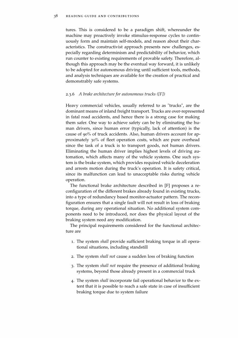
38 reading guide and contributions
tures. This is considered to be a paradigm shift, whereunder themachine may proactively invoke stimulus-response cycles to contin-uously form and maintain self-models, and reason about their char-acteristics. The constructivist approach presents new challenges, es-pecially regarding determinism and predictability of behavior, whichrun counter to existing requirements of provable safety. Therefore, al-though this approach may be the eventual way forward, it is unlikelyto be adopted for autonomous driving until sufficient tools, methods,and analysis techniques are available for the creation of practical anddemonstrably safe systems.
2.3.6 A brake architecture for autonomous trucks ([F])
Heavy commercial vehicles, usually referred to as "trucks", are thedominant means of inland freight transport. Trucks are over-representedin fatal road accidents, and hence there is a strong case for makingthem safer. One way to achieve safety can be by eliminating the hu-man drivers, since human error (typically, lack of attention) is thecause of 90% of truck accidents. Also, human drivers account for ap-proximately 30% of fleet operation costs, which are pure overheadsince the task of a truck is to transport goods, not human drivers.Eliminating the human driver implies highest levels of driving au-tomation, which affects many of the vehicle systems. One such sys-tem is the brake system, which provides required vehicle decelerationand arrests motion during the truck’s operation. It is safety critical,since its malfunction can lead to unacceptable risks during vehicleoperation.
The functional brake architecture described in [F] proposes a re-configuration of the different brakes already found in existing trucks,into a type of redundancy based monitor-actuator pattern. The recon-figuration ensures that a single fault will not result in loss of brakingtorque, during any operational situation. No additional system com-ponents need to be introduced, nor does the physical layout of thebraking system need any modification.
The principal requirements considered for the functional architec-ture are
1. The system shall provide sufficient braking torque in all opera-tional situations, including standstill
2. The system shall not cause a sudden loss of braking function
3. The system shall not require the presence of additional brakingsystems, beyond those already present in a commercial truck
4. The system shall incorporate fail operational behavior to the ex-tent that it is possible to reach a safe state in case of insufficientbraking torque due to system failure

2.3 executive summary of contributions 39
5. The system shall not increase the probability of a "Vehicle offroad" condition i.e. a situation where the mission needs to beaborted, and a secondary vehicle is needed for towing to a work-shop
Figure 15: General pattern for brake architecture
The publication focuses on absence of braking torque, and there-fore only discusses hazards in the ’Omission’, ’Too little’, and ’Toolate’ categories. The general architectural pattern is shown in Figure15. It consists of a primary and secondary brake system with threedifferent communication buses and distinct vehicle speed sensors foreach brake system. It is shown in [F.III.B] that no single failure insuch a system can lead to total loss of brake torque. The applicationof the pattern to the brake systems usually found in existing trucks isshown in Figure 16. The existing brakes are grouped into a categoryconsisting exclusively of the parking brake, and another category con-sisting of the wheel brakes and other auxiliary retardation systemslike exhaust brakes, retarder, electrical machine etc., as available onthe truck. The parking brake is mapped onto the secondary brake inthe general pattern, while the rest of the brakes are mapped onto theprimary brake.
A preliminary reliability analysis [F.III.B] indicates that an orderof magnitude improvement in reliability may be expected due to thereconfiguration advocated by the proposed architecture. A simula-tion study setup to investigate the effect of Omission, Tool Little, andToo Late failures indicates satisfactory braking performance in theirpresence. For example, the simulation of an Omission failure in theprimary brakes (shown in Figure 17) indicates only a small increasein braking distance.

40 reading guide and contributions
Figure 16: Mapping from existing brake architecture to general pattern
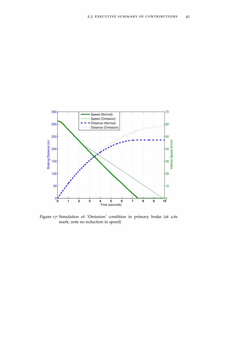
2.3 executive summary of contributions 41
0 1 2 3 4 5 6 7 8 9 100
50
100
150
200
250
300
350
Bra
kin
g D
ista
nce
(m
)
0 1 2 3 4 5 6 7 8 9 100
10
20
30
40
50
60
70
Time (seconds)
Ve
hic
le S
pe
ed
(km
/h)
Speed (Normal)
Speed (Omission)
Distance (Normal)
Distance (Omission)
Figure 17: Simulation of ’Omission’ condition in primary brake (at 2.6smark, note no reduction in speed)

3D I S C U S S I O N
"We choose to go to the Moonin this decade and do theother things, not because theyare easy, but because they arehard."
— John F. Kennedy, 1962
The hypothesis underlying this thesis work, introduced in Section1.4 was
hypothesis : A reference architecture for highly automateddriving exists, which is general enough to be repeatedly instan-tiated to provide sufficient solutions for a variety of automateddriving tasks in a variety of scenarios. Such a reference architec-ture will contain solution patterns and other value additions tohelp architects build apposite solutions for automated driving,especially with regards to performance and safety.
The reference architecture for cooperative driving has been success-fully instantiated twice. In its extended form as a reference architec-ture for autonomous driving, it has been examined, instantiated, andvalidated twice. Most elements of the reference architecture, such asthe world model, decision and control, vehicle abstraction, and theirinterconnections have been retained and sometimes, reused, acrossthe instantiations. The algorithms within the elements, as well asthe mapping of the elements to execution platform have undergonechanges with each instantiation. The guidelines given for instantia-tion have helped to make implementation choices in real projects. Thearchitectures have been peer reviewed by practicing engineers work-ing in the area of heavy commercial vehicles, as well as passenger cars.The scientific description of the architectures, in the form of publica-tions, has been peer reviewed by other researchers at workshops, andacademic journals. All of this has contributed to high confidence inthe reference architectures and in the absence of any contrary evi-dence so far, it is reasonable to claim that the hypothesis is valid.
The research question
research question : What is a suitable reference architec-ture for highly automated driving?
is answered by the architecture description and artifacts providedby the combination of academic publications, technical reports and
43
44 discussion
implemented vehicles. The answer states the main requirements, prin-ciples, and architectural patterns. It also outlines the technologies anddevelopment processes for implementing highly automated drivingsystems.
The method of engineering design turns out to be a good choicefor this kind research. The task of actually producing a working pro-totype uncovered endless details that went into strengthening the ref-erence architecture. For example, the splitting up of the world modelinto two parts, relating to the vehicle platform and the cognitive driv-ing intelligence, instead of a unified model, is a direct result of nu-merous attempts to create a unified world model with sufficient per-formance. This turns to be rather difficult with existing technologyand almost always puts excessively high computational processingrequirements on the computer executing the world model. Similarly,the split between diagnostics and fault management, as well as de-liberative and reactive control aspects are heavily influenced by ex-periences with concrete system implementations. The generalizationsfrom these implementations have found their way into the referencearchitectures, adding a value that may not have been possible with-out this approach. The same holds true for the topics of selectingexecution environments and communication technologies, which arementioned as considerations for instantiating the reference architec-ture.
A criticism that is sometimes leveled at a functional reference archi-tecture is that it lacks the technical details (like choice of implemen-tation technologies) to create a practical implementation. This missesthe entire point of the reference architecture. The details are missingprecisely because they are implementation specific. The reference ar-chitecture is supposed to be a broad and somewhat abstract guidelinethat can be enhanced with rich practical detail specific to a project’srequirements. The details of the implementations we have made areavailable in most cases, but even in our own experiments, we havecome across a typical situation: Technical architectures and imple-mentation details are considered valuable intellectual property andmost companies are reluctant to share more than superficial informa-tion without strict non-disclosure agreements. Therefore, we do notexpect the scientific literature to be flooded with detailed technicalarchitectures anytime soon.
Other domains like robotics and AI have a strong influence onhighly automated driving. Most research prototypes borrow heavilynot just from mathematical results in these domains, but also functionlibraries, middleware, data visualization, and analysis tools. Theseborrowed items do not always meet the robustness, safety, and reli-ability requirements of the automotive domain. It will therefore beinteresting to see whether they are developed further into reusable,automotive grade, open source components, or whether automotive

discussion 45
companies will develop proprietary and custom tools based on theopen source technologies. Within Europe, the initiative for Cyber-Physical Systems Engineering (CPSE Labs) [1] acknowledges the needto create open platforms for autonomous systems, but it is unclear towhat extent these platforms will be applicable to, and adopted for,highly autonomous driving.
An important consideration for automotive companies is the topicof legacy. It is not enough to prepare a good clean sheet architecture;ways to encapsulate legacy and migration paths from existing archi-tectures to new ones need to be considered. One way to do this is towrap the existing functionality via a ’gateway’, which abstracts howthe legacy systems work. This is more or less similar to the approachtaken in the Scoop project, where the entire vehicle motion and actu-ation systems are behind a gateway that exchanges a fixed set of mes-sages. While simple in theory, there are complicating factors that limitthis practice. One factor is that due to the way legacy systems haveevolved, the allocation of functionality to control units is not alwaysoptimal. For example, it is often the case that the cruise control func-tion resides in the engine management system, because this is oftenthe first system to which electronic control is applied. It remains therefor legacy reasons, but from the viewpoint of a clean sheet design, theengine management system is not the ideal location for cruise control,especially when other traction management systems are present, orwhen the cruise control is being evolved to adaptive or cooperativecruise control. Another factor is that legacy systems can not alwaysbe directly reused, even though they have all the needed function-ality. This is because of extra-functional requirements like reliabilityand safety. Both these extra-functional requirements are expected tobe stricter for autonomous driving, because the societal acceptanceof safety incidents triggered by autonomous vehicles is likely to belower than for human operated vehicles. The existing designs there-fore need to be upgraded to meet the more stringent extra-functionalrequirements. The brake system architecture described in [F] is anexample of this type of upgrade.
The matter of constructionist vs constructivist AI architectures, out-lined in [E.1.6] is a trickier problem. The constructionist approach ofcareful, cross-checked, hand-crafted designs has proven essential andsuccessful in the construction of safety critical systems. Such systemdesigns are marked by conservative approaches and favor extremedeterminism, predictability, and regulated changes to system behav-ior during runtime. To replace this approach by a "wilder" scenariowhere the machine does not include carefully crafted models, butrather builds them during operation, necessarily by a trial-and-errorapproach sounds unreasonable. Yet, if this is indeed the way forward,due to reasons of complexity management and endowing the ma-chine with a sense of "Self", then there still need to be hybrid architec-

46 discussion
tures where both approaches can be combined into one. But beyondthe purely philosophical issues, another problem is the lack of interac-tion between the communities engaging in the research. Researchersworking on machine consciousness or the theory of Mind rarely inter-act with those working on automotive functional safety, for example.Such interaction is essential to accelerate the rate of progress in auto-mated driving.
In the context of highly automated driving, an interesting ques-tion is: How intelligent is intelligent enough? How smart does thecar of the future really need to be? While answering this question, itis necessary to consider that an autonomous vehicle is expected tobe just one part of a much larger Intelligent Transportation System(ITS). Future urban (and even non-urban) transport scenarios are ex-pected to be inter-connected grids of data streams between vehicles,infrastructure, government agencies, and private companies. Latestcars already have the capability to report operational data to manu-facturers, or receive over-the-air upgrades. It is reasonable to expectan increase in such capabilities for different purposes. Such a trend isalready evident in aviation, where operational data from the engines,for example, is streamed back to operations and maintenance bases.Patents for active teleoperation of autonomous vehicles have alreadybeen issued. Experiments for regulating vehicle speeds at traffic in-tersections, via direct commands to the vehicle drivetrain, are alsobeing conducted. Thus, the balance and distribution of intelligencebetween on-board and off-board systems is an interesting area forfuture work. There are a large number of stakeholders in this area,including automotive companies, governments, regulatory bodies, in-surance companies, traffic management authorities, and vehicle own-ers. It is reasonable to expect that the stakeholders have their ownvested interests which will more often than not be at odds with eachother. So it will be fascinating to see how the situation evolves withinthe next 10-15 years. As with many cases, those ahead on the tech-nology curve will be first-to-market and establish the trends, whilepossibly encountering risks that were improperly assessed.
3.1 future work
This thesis work has considered notions from the relatively abstractareas of self-awareness and consciousness to very concrete implemen-tations of working vehicles. The balance between abstract and con-crete has been struck in the form of reusable reference architecturesthat bring demonstrable value to the field.
The work can be extended along at least five directions
1. Development of methods and tools for safety analysis and as-surance. At the moment, the entire burden of ensuring safety isplaced on the team instantiating the reference architecture to a

3.1 future work 47
technical architecture. The supporting research needs to includebetter hazard analysis (current techniques depend on the avail-ability of a human to take control), redundancy and monitoringpatterns, and safety contracts and their implementation.
2. Development of supporting Model Based Systems Engineeringprocesses and tools. As a parallel with the concrete engineer-ing work undertaken in this thesis, proposed Architectural De-scription Languages (ADLs) and analysis techniques need to becomplemented by mature tools that can be used by practicingengineers. Similarly, tool adapters and data-interchange linksfor facilitating "round trip" data flows between tools are neces-sary to bring MBSE techniques into practice
3. Research for accelerating and reducing the testing, verification,validation and qualification (TVVQ) efforts. Rapid TVVQ is nec-essary for achieving comprehensive test coverage, deployingnew research results, and enabling continuous integration, andfixing post-development problems.
4. Development of reusable, scalable, high maturity, and safetycritical platforms for implementing highly automated drivingsystems. These platforms should ideally synchronize with theMBSE development methods and tools to maximize verificationof system properties at the modeling and implementation lev-els.
5. Closer collaboration between research from AI/computationalconsciousness and domains of control, embedded systems, andsafety so as to create practical methods for enabling self-awarenessin machines.
Items 1. and 2. above shall be examined by the follow-up project,ARCHER, in collaboration with Scania CV AB. Item 4. is being exam-ined via the European innovation actions for Cyber-Physical Systems(CPS).
Research in highly automated driving is still in its infancy. Thisthesis work provides one part of a much larger puzzle.


B I B L I O G R A P H Y
[1] Cyber-Physical Systems Engineering Labs. http://www.
cpse-labs.eu/. Accessed: 2015-10-02.
[2] IEEE Standard Glossary of Software Engineering Terminology.IEEE Std 610.12-1990, pages 1–84, Dec 1990. doi: 10.1109/IEEESTD.1990.101064.
[3] ISO/IEC/IEEE 42010:2011 Systems and software engineering —Architecture description. International Organization for Stan-dardization, 2011.
[4] SAE J3016: Taxonomy and Definitions for Terms Related to On-Road Motor Vehicle Automated Driving Systems. Sae Interna-tional, 2014.
[5] J. Albus. Outline for a theory of intelligence. Systems, Man andCybernetics, IEEE Transactions, 21(3):473–509, 1991. doi: 10.1109/21.97471.
[6] TLJ Ferris. Engineering design as research. In Research Method-ologies, Innovations and Philosophies in Software Systems Engineer-ing and Information Systems. IGI Global, February 2012. doi:10.4018/978-1-4666-0179-6.
[7] Alan R. Hevner, Salvatore T. March, Jinsoo Park, and Sudha Ram.Design science in information systems research. MIS Quarterly,28(1):75–105, March 2004. ISSN 0276-7783.
[8] INCOSE Definition. What is Systems Engineering? http://www.
incose.org/AboutSE/WhatIsSE. Accessed: 2015-10-02.
[9] INCOSE SE Vision 2020 (INCOSE-TP-2004-004-02). ModelBased Systems Engineering. http://oldsite.incose.org/
ProductsPubs/pdf/SEVision2020_20071003_v2_03.pdf, 2007.Accessed: 2015-10-23.
[10] INCOSE Systems Engineering Handbook. What is a System?http://sebokwiki.org/wiki/What_is_a_System%3F. Accessed:2015-10-23.
[11] Philippe Kruchten. The Rational Unified Process. Rational Soft-ware White Paper. Addison-Wesley, 2003. ISBN 0321197704.
[12] John McCarthy. What is artificial intelligence. http://
www-formal.stanford.edu/jmc/whatisai/whatisai.html. Ac-cessed: 2015-10-11.
49
50 bibliography
[13] A. Meystel. Autonomous Mobile Robots: Vehicles with CognitiveControl. Series in automation. World Scientific, 1991. ISBN9789971500894.
[14] National Highway Traffic Safety Administration (NHTSA). Crit-ical Reasons for Crashes Investigated in the National Motor Ve-hicle Crash Causation Survey. http://www-nrd.nhtsa.dot.gov/pubs/812115.pdf. Accessed: 2015-10-17.
[15] Oxford dictionaris. Definition of consciousness. http:
//www.oxforddictionaries.com/us/definition/american_
english/consciousness. Accessed: 2015-10-23.
[16] D L Parnas and P C Clements. A rational design process: Howand why to fake it. IEEE Transactions on Software Engineering, 12
(2):251–257, February 1986. ISSN 0098-5589.
[17] Herbert A. Simon. The architecture of complexity. Proceedings ofthe American Philosophical Society, 106(6):pp. 467–482, 1962. ISSN0003049X.
[18] L. von Bertalanffy. General System Theory: Foundations, Develop-ment, Applications. Penguin University Books. G. Braziller, 2003.ISBN 9780807604533.