
REFCL application draft (master)
60
Powercor Contingent project application REFCL program: tranche t hree August 2019
Transcript of REFCL application draft (master)
PowercorContingent project application REFCL program: tranche three
August 2019

2 Powercor contingent project application | REFCL program: tranche three
This page is intentionally blank.
Powercor contingent project application | REFCL program: tranche three 3
1 EXECUTIVE SUMMARY ......................................................................................... 5
2 BACKGROUND ..................................................................................................... 9
2.1 Powerline Bushfire Safety Taskforce .............................................................................................................. 11
2.2 Regulatory impact statement ......................................................................................................................... 12
2.3 Amended Bushfire Mitigation Regulations .................................................................................................... 12
2.4 Bushfire Mitigation Civil Penalties Scheme .................................................................................................... 12
3 OUR REFCL PROGRAM ....................................................................................... 13
3.1 Our REFCL tranches ........................................................................................................................................ 15
3.2 Our experience in deploying REFCLs .............................................................................................................. 17
4 REGULATORY REQUIREMENTS ........................................................................... 19
4.1 Trigger event................................................................................................................................................... 21
4.2 Materiality threshold ...................................................................................................................................... 23
4.3 Assessment of forecast costs ......................................................................................................................... 23
5 KEY DIFFERENCES FROM TRANCHE TWO ........................................................... 25
5.1 Network characteristics .................................................................................................................................. 27
5.2 Zone substation requirements ....................................................................................................................... 28
5.3 HV customers ................................................................................................................................................. 28
5.4 Balancing units................................................................................................................................................ 29
5.5 Asset resilience testing ................................................................................................................................... 30
5.6 Increased material costs from suppliers ........................................................................................................ 31
5.7 Testing trailer.................................................................................................................................................. 31
5.8 Spare GFN ....................................................................................................................................................... 31
6 FORECAST EXPENDITURE ................................................................................... 33
6.1 Substation works ............................................................................................................................................ 36
6.2 Feeder works .................................................................................................................................................. 39
6.3 Removal of replacement expenditure ............................................................................................................ 45
6.4 Materials cost forecast ................................................................................................................................... 45
6.5 Labour cost forecast ....................................................................................................................................... 46
6.6 Contract expenditure ..................................................................................................................................... 51
6.7 Forecast expenditure summary ...................................................................................................................... 51
6.8 Forecast incremental revenue ........................................................................................................................ 52
A ATTACHMENT LIST ............................................................................................. 53
Contents
4 Powercor contingent project application | REFCL program: tranche three
B COMPLIANCE CHECKLIST ................................................................................... 57
1Executive summary

6 Powercor contingent project application | REFCL program: tranche three
This page is intentionally blank.
Powercor contingent project application | REFCL program: tranche three 7
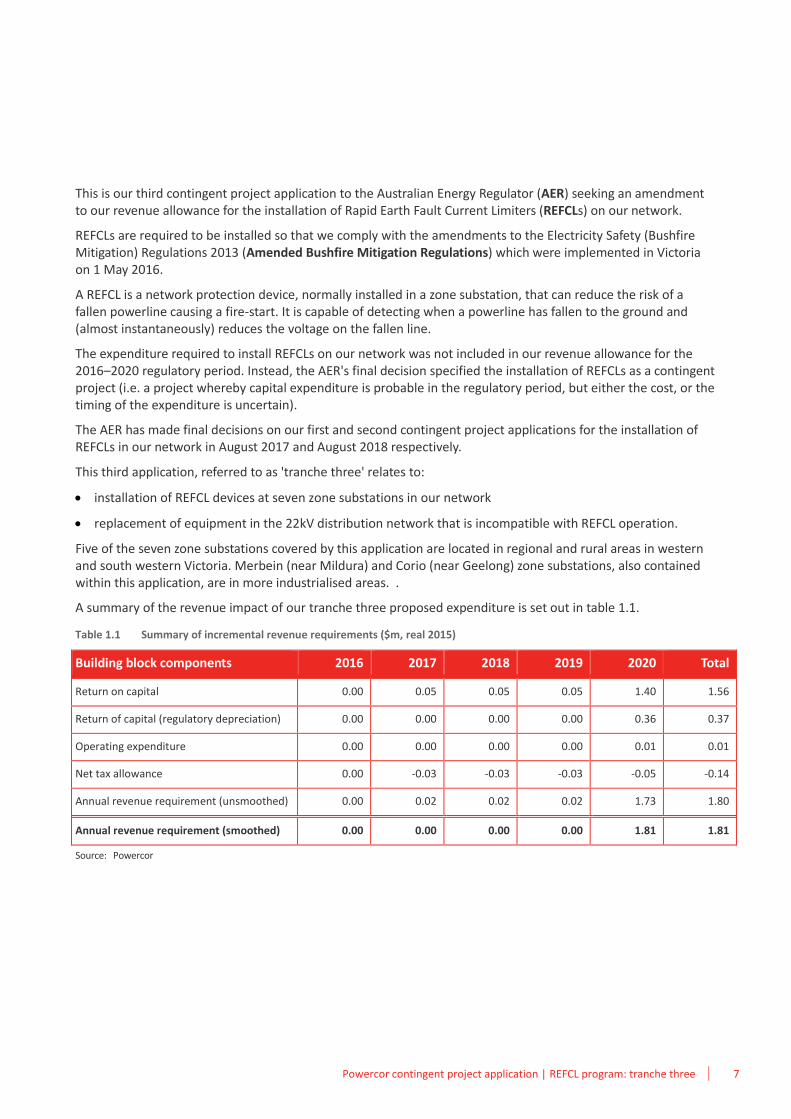
This is our third contingent project application to the Australian Energy Regulator (AER) seeking an amendment to our revenue allowance for the installation of Rapid Earth Fault Current Limiters (REFCLs) on our network.
REFCLs are required to be installed so that we comply with the amendments to the Electricity Safety (Bushfire Mitigation) Regulations 2013 (Amended Bushfire Mitigation Regulations) which were implemented in Victoria on 1 May 2016.
A REFCL is a network protection device, normally installed in a zone substation, that can reduce the risk of a fallen powerline causing a fire-start. It is capable of detecting when a powerline has fallen to the ground and (almost instantaneously) reduces the voltage on the fallen line.
The expenditure required to install REFCLs on our network was not included in our revenue allowance for the 2016–2020 regulatory period. Instead, the AER's final decision specified the installation of REFCLs as a contingent project (i.e. a project whereby capital expenditure is probable in the regulatory period, but either the cost, or the timing of the expenditure is uncertain).
The AER has made final decisions on our first and second contingent project applications for the installation of REFCLs in our network in August 2017 and August 2018 respectively.
This third application, referred to as 'tranche three' relates to:
• installation of REFCL devices at seven zone substations in our network
• replacement of equipment in the 22kV distribution network that is incompatible with REFCL operation.
Five of the seven zone substations covered by this application are located in regional and rural areas in western and south western Victoria. Merbein (near Mildura) and Corio (near Geelong) zone substations, also contained within this application, are in more industrialised areas. .
A summary of the revenue impact of our tranche three proposed expenditure is set out in table 1.1.
Table 1.1 Summary of incremental revenue requirements ($m, real 2015)
Building block components 2016 2017 2018 2019 2020 Total
Return on capital 0.00 0.05 0.05 0.05 1.40 1.56
Return of capital (regulatory depreciation) 0.00 0.00 0.00 0.00 0.36 0.37
Operating expenditure 0.00 0.00 0.00 0.00 0.01 0.01
Net tax allowance 0.00 -0.03 -0.03 -0.03 -0.05 -0.14
Annual revenue requirement (unsmoothed) 0.00 0.02 0.02 0.02 1.73 1.80
Annual revenue requirement (smoothed) 0.00 0.00 0.00 0.00 1.81 1.81
Source: Powercor
1 Executive summary

8 Powercor contingent project application | REFCL program: tranche three
This page is intentionally blank.
2Background

10 Powercor contingent project application | REFCL program: tranche three
This page is intentionally blank.
Powercor contingent project application | REFCL program: tranche three 11
A contingent project is a project assessed by the AER as being reasonably required, but for which uncertainty exists regarding the timing or costs. The associated expenditure, therefore, is excluded from ex-ante capital expenditure allowances until a defined trigger event occurs.
At the time of making its final decision for Powercor for the 2016–2020 regulatory control period, expected amendments to the Electricity Safety (Bushfire Mitigation) Regulations 2013 had not been finalised. To ensure consumers did not pay for an uncertain event, the AER's final decision accepted the installation of REFCLs as a contingent project.
This section sets out background regarding the requirement to install REFCLs, including the following:
• the Powerline Bushfire Safety Taskforce (PBST)
• the Regulatory Impact Statement (RIS)
• the Amended Bushfire Mitigation Regulations
• the Electricity Safety Amendment (Bushfire Mitigation Civil Penalties Scheme).
Further background on the relevant regulatory requirements under the National Electricity Rules (the Rules, or NER) is set out in section 4.
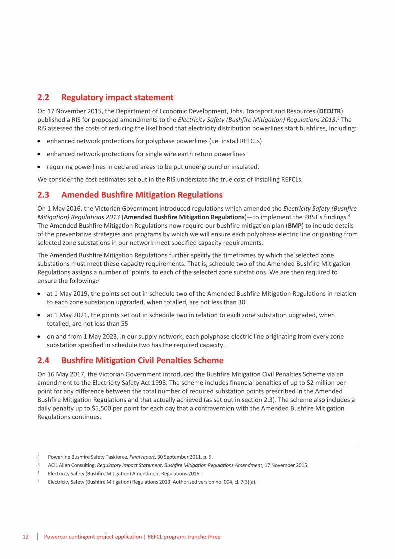
2.1 Powerline Bushfire Safety Taskforce
Following the Black Saturday bushfires in 2009, the Victorian Government established the Victorian Bushfire Royal Commission (VBRC) to consider how bushfires can be better prevented and managed in the future. In July 2010, the VBRC's final report was provided to the Victorian Government.
The VBRC's final report made a number of recommendations, including the following:1
[t]he State amend the Regulations under Victoria’s Electricity Safety Act 1998 and otherwise take such steps as may be required to give effect to the following:
– the progressive replacement of all SWER (single-wire earth return) power lines in Victoria with aerial bundled cable, underground cabling or other technology that delivers greatly reduced bushfire risk…
– the progressive replacement of all 22-kilovolt distribution feeders with aerial bundled cable, underground cabling or other technology that delivers greatly reduced bushfire risk as the feeders reach the end of their engineering lives.
As part of the Victorian Government's consideration of the recommendations made by the VBRC in its final report, the PBST was established. The PBST was required to investigate new cost efficient and effective technologies and operational practices to reduce catastrophic bushfire risk.
The PBST identified REFCLs installed in zone substations as an efficient and effective technology. A REFCL is a network protection device, normally installed in a zone substation, that can reduce the risk of a fallen powerline causing a fire-start. It is capable of detecting when a powerline has fallen to the ground and (almost instantaneously) reduces the voltage on the fallen line.
The PBST estimated the relative reduction in the likelihood of multi-phase powerlines starting bushfires to be approximately 70 per cent with the installation of REFCLs.2
1 2009 Victorian Bushfires Royal Commission, Final Report, Summary, July 2010, recommendation 27.
2 Background
12 Powercor contingent project application | REFCL program: tranche three
2.2 Regulatory impact statement
On 17 November 2015, the Department of Economic Development, Jobs, Transport and Resources (DEDJTR) published a RIS for proposed amendments to the Electricity Safety (Bushfire Mitigation) Regulations 2013.3 The RIS assessed the costs of reducing the likelihood that electricity distribution powerlines start bushfires, including:
• enhanced network protections for polyphase powerlines (i.e. install REFCLs)
• enhanced network protections for single wire earth return powerlines
• requiring powerlines in declared areas to be put underground or insulated.
We consider the cost estimates set out in the RIS understate the true cost of installing REFCLs.
2.3 Amended Bushfire Mitigation Regulations
On 1 May 2016, the Victorian Government introduced regulations which amended the Electricity Safety (Bushfire Mitigation) Regulations 2013 (Amended Bushfire Mitigation Regulations)—to implement the PBST's findings.4 The Amended Bushfire Mitigation Regulations now require our bushfire mitigation plan (BMP) to include details of the preventative strategies and programs by which we will ensure each polyphase electric line originating from selected zone substations in our network meet specified capacity requirements.
The Amended Bushfire Mitigation Regulations further specify the timeframes by which the selected zone substations must meet these capacity requirements. That is, schedule two of the Amended Bushfire Mitigation Regulations assigns a number of 'points' to each of the selected zone substations. We are then required to ensure the following:5
• at 1 May 2019, the points set out in schedule two of the Amended Bushfire Mitigation Regulations in relation to each zone substation upgraded, when totalled, are not less than 30
• at 1 May 2021, the points set out in schedule two in relation to each zone substation upgraded, when totalled, are not less than 55
• on and from 1 May 2023, in our supply network, each polyphase electric line originating from every zone substation specified in schedule two has the required capacity.
2.4 Bushfire Mitigation Civil Penalties Scheme
On 16 May 2017, the Victorian Government introduced the Bushfire Mitigation Civil Penalties Scheme via an amendment to the Electricity Safety Act 1998. The scheme includes financial penalties of up to $2 million per point for any difference between the total number of required substation points prescribed in the Amended Bushfire Mitigation Regulations and that actually achieved (as set out in section 2.3). The scheme also includes a daily penalty up to $5,500 per point for each day that a contravention with the Amended Bushfire Mitigation Regulations continues.
2 Powerline Bushfire Safety Taskforce, Final report, 30 September 2011, p. 5. 3 ACIL Allen Consulting, Regulatory Impact Statement, Bushfire Mitigation Regulations Amendment, 17 November 2015. 4 Electricity Safety (Bushfire Mitigation) Amendment Regulations 2016. 5 Electricity Safety (Bushfire Mitigation) Regulations 2013, Authorised version no. 004, cl. 7(3)(a).
3Our REFCL program

14 Powercor contingent project application | REFCL program: tranche three
This page is intentionally blank.
Powercor contingent project application | REFCL program: tranche three 15
This section provides an overview of our REFCL program and experience to-date from deploying and commissioning REFCLs.
3.1 Our REFCL tranches
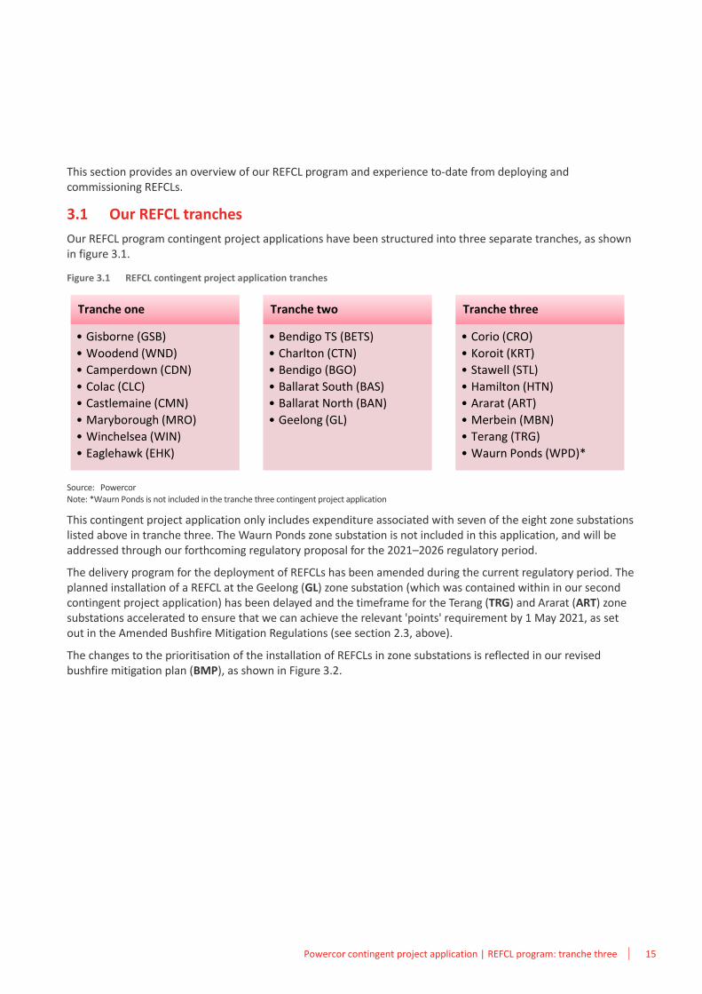
Our REFCL program contingent project applications have been structured into three separate tranches, as shown in figure 3.1.
Figure 3.1 REFCL contingent project application tranches
Source: Powercor Note: *Waurn Ponds is not included in the tranche three contingent project application
This contingent project application only includes expenditure associated with seven of the eight zone substations listed above in tranche three. The Waurn Ponds zone substation is not included in this application, and will be addressed through our forthcoming regulatory proposal for the 2021–2026 regulatory period.
The delivery program for the deployment of REFCLs has been amended during the current regulatory period. The planned installation of a REFCL at the Geelong (GL) zone substation (which was contained within in our second contingent project application) has been delayed and the timeframe for the Terang (TRG) and Ararat (ART) zone substations accelerated to ensure that we can achieve the relevant 'points' requirement by 1 May 2021, as set out in the Amended Bushfire Mitigation Regulations (see section 2.3, above).
The changes to the prioritisation of the installation of REFCLs in zone substations is reflected in our revised bushfire mitigation plan (BMP), as shown in Figure 3.2.
Tranche one
• Gisborne (GSB)
• Woodend (WND)
• Camperdown (CDN)
• Colac (CLC)
• Castlemaine (CMN)
• Maryborough (MRO)
• Winchelsea (WIN)
• Eaglehawk (EHK)
Tranche two
• Bendigo TS (BETS)
• Charlton (CTN)
• Bendigo (BGO)
• Ballarat South (BAS)
• Ballarat North (BAN)
• Geelong (GL)
Tranche three
• Corio (CRO)
• Koroit (KRT)
• Stawell (STL)
• Hamilton (HTN)
• Ararat (ART)
• Merbein (MBN)
• Terang (TRG)
• Waurn Ponds (WPD)*
3 Our REFCL program
16 Powercor contingent project application | REFCL program: tranche three
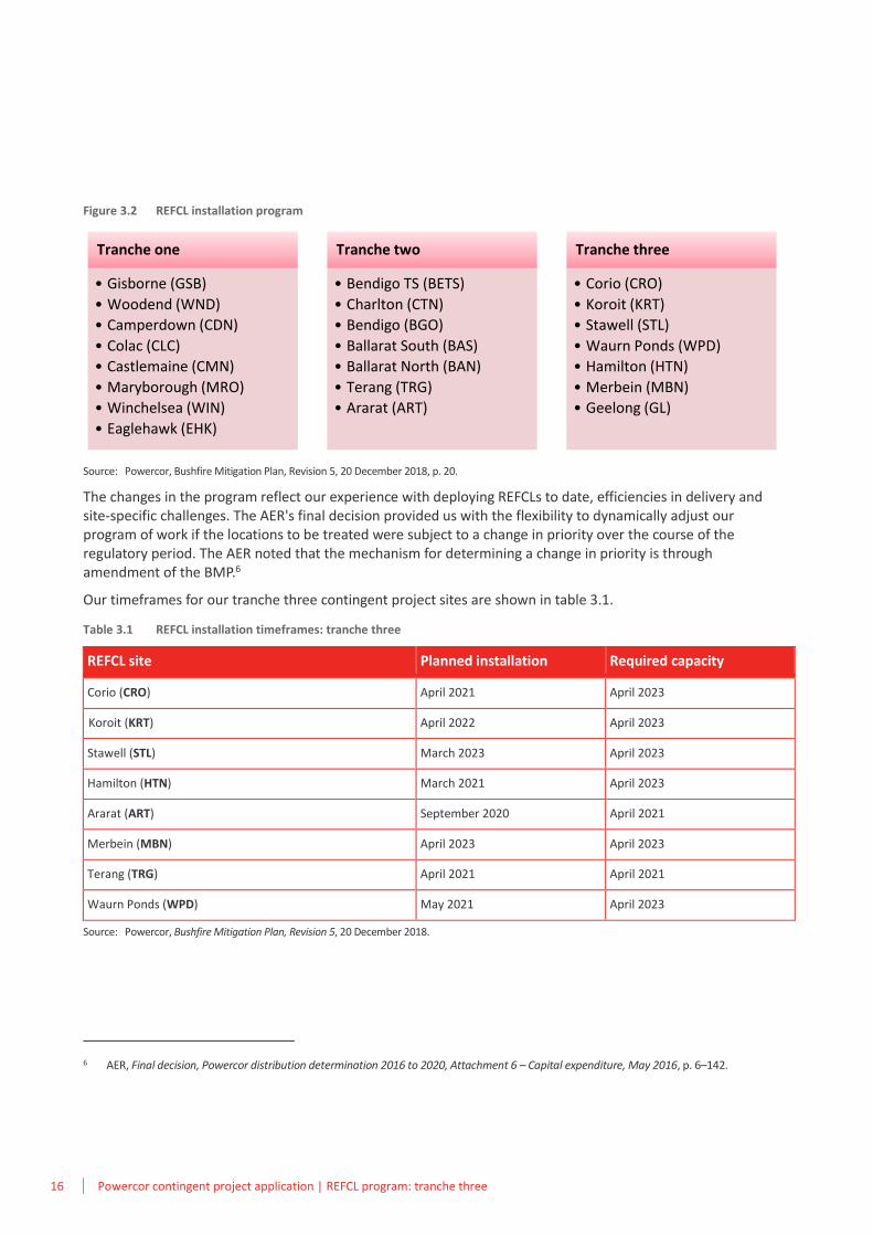
Figure 3.2 REFCL installation program
Source: Powercor, Bushfire Mitigation Plan, Revision 5, 20 December 2018, p. 20.
The changes in the program reflect our experience with deploying REFCLs to date, efficiencies in delivery and site-specific challenges. The AER's final decision provided us with the flexibility to dynamically adjust our program of work if the locations to be treated were subject to a change in priority over the course of the regulatory period. The AER noted that the mechanism for determining a change in priority is through amendment of the BMP.6
Our timeframes for our tranche three contingent project sites are shown in table 3.1.
Table 3.1 REFCL installation timeframes: tranche three
REFCL site Planned installation Required capacity
Corio (CRO) April 2021 April 2023
Koroit (KRT) April 2022 April 2023
Stawell (STL) March 2023 April 2023
Hamilton (HTN) March 2021 April 2023
Ararat (ART) September 2020 April 2021
Merbein (MBN) April 2023 April 2023
Terang (TRG) April 2021 April 2021
Waurn Ponds (WPD) May 2021 April 2023
Source: Powercor, Bushfire Mitigation Plan, Revision 5, 20 December 2018.
6 AER, Final decision, Powercor distribution determination 2016 to 2020, Attachment 6 – Capital expenditure, May 2016, p. 6–142.
Tranche one
• Gisborne (GSB)
• Woodend (WND)
• Camperdown (CDN)
• Colac (CLC)
• Castlemaine (CMN)
• Maryborough (MRO)
• Winchelsea (WIN)
• Eaglehawk (EHK)
Tranche two
• Bendigo TS (BETS)
• Charlton (CTN)
• Bendigo (BGO)
• Ballarat South (BAS)
• Ballarat North (BAN)
• Terang (TRG)
• Ararat (ART)
Tranche three
• Corio (CRO)
• Koroit (KRT)
• Stawell (STL)
• Waurn Ponds (WPD)
• Hamilton (HTN)
• Merbein (MBN)
• Geelong (GL)
Powercor contingent project application | REFCL program: tranche three 17
3.2 Our experience in deploying REFCLs
We continue to learn about the deployment and operation of REFCLs from our trials at Woodend and Gisborne and the remainder of tranche one and tranche two. The key issues are set out below.
3.2.1 Gisborne and Woodend
The AER's final determination for the 2016–2020 regulatory period included funding to install REFCLs on our network—at our Gisborne (GSB) and Woodend (WND) zone substations. This funding was separate to the tranche one contingent project application.
We successfully installed and commissioned the GSB zone substation with a single REFCL in October 2016. Energy Safe Victoria (ESV) confirmed that we met the performance requirements set out in the Amended Bushfire Mitigation Regulations (i.e. 'required capacity') in August 2018.7
On 6 March 2019, ESV confirmed that we met the performance requirements at the WND zone substation.
Our GSB and WND experience helped demonstrate how operating a REFCL may impact our overall network (with a particular focus on surrounding system resilience, capacitive balancing, and operational matters). The learnings from these trials included:
• achieving performance requirements may necessitate multiple REFCL units at particular zone substations
• the capacitive charging current of the network being protected should be kept to within 81 – 108A
• only selected surge arrestor types require replacement
• only selected Automatic Circuit Reclosers (ACRs) require replacement
• a multi-faceted approach to capacitive balancing is required to ensure a cost effective means of meeting our performance and fault detection requirements under the Amended Bushfire Mitigation Regulations
• a number of existing assets appear resilient to the operation of a REFCL (e.g. high voltage (HV) insulators and distribution transformers).
Additional technical challenges were experienced at WND. WND is an older zone substation compared to GSB, and more typical for the Powercor network. The particular challenges that we faced included:
• a large number of underground cable failures
• a change to the rebalancing approach
• inaccuracy of existing instrumentation transformers
• longer than expected timeframes for commissioning
• additional capacitance works and equipment required to meet the 'required capacity'.
3.2.2 Tranche one of our REFCL deployment program
In October 2018, February and March 2019, ESV confirmed that we met the performance requirements for most of the remaining zone substations in tranche one, namely Camperdown (CDN), Eaglehawk (EHK), Winchelsea
7 The required capacity is defined in the Amended Bushfire Mitigation Regulations.
18 Powercor contingent project application | REFCL program: tranche three
(WIN), Castlemaine (CMN) and Maryborough (MRO).8 This delivered Powercor the required 30 'points' by 1 May 2019, as set out in the Amended Bushfire Mitigation Regulations.
ESV noted that the acceptance is subject to Powercor meeting specific conditions by 30 November 2019, or by the time that the Country Fire Authority declares a fire danger period in 2019 for any area that includes any part of the relevant network, whichever is sooner. To meet the specific conditions, Powercor must:
• investigate, pursue resolution of, and provide a report to ESV on the materiality of calibration to achieve the required capacity on the network, or on electricity networks in general
• investigate and demonstrate resolution of the harmonics issue through repeated testing on the network in 2019
• investigate and demonstrate resolution of the issue related to sampling of admittance values through continued and repeated testing of tranche one sites throughout 2019
• investigate and demonstrate resolution of the issue related to inverter trips through continued and repeated testing of tranche one sites throughout 2019.
Through the tranche one deployment program, we have a greater understanding of the technical challenges associated with the REFCL and interactions with the network and equipment. Key learnings include:
• network augmentation can pose a risk to REFCL sensitivity
• pre-testing of the resilience of assets to withstand the operation of the REFCL is required
• the approach to balancing should be more dynamic to maintain the ability to switch and operate the network in a safe, efficient and reliable manner
• the greater the distance from the zone substation to any underground cable increases the damping and total charging current requirements for the zone substation, increasing the number of REFCLs required
• deployment and commissioning take much longer than anticipated
• there is a decrease in reliability to customers once the REFCL is in operation.
3.2.3 Tranche two of our REFCL deployment program
Our tranche two REFCL deployment program has just commenced.
We have commenced network hardening and zone substation works at the Charlton (CTN) and Ballarat North (BAN) zone substations. The works are expected to be completed in early 2020.
The Bendigo (BGO), Bendigo Terminal Station (BETS) and Ballarat South (BAS) zone substation hardening works are expected to be completed in 2020.
Powercor must achieve 55 'points' by 1 May 2021 through the tranche two program. A major challenge associated with the tranche two program is ensuring that high voltage (HV) customer connections can either withstand the higher voltages occurring during REFCL operation, or be isolated from the network. The works are now the responsibility of the HV customer. There are ongoing discussions with relevant stakeholders to determine the operational arrangements if HV customers are not ready before the REFCLs are commissioned.
8 Powercor has not yet met the performance requirements at Colac (CLC) zone substation.
4Regulatory requirements

20 Powercor contingent project application | REFCL program: tranche three
This page is intentionally blank.
Powercor contingent project application | REFCL program: tranche three 21
Under the Rules, a distributor may apply to the AER during a regulatory period to amend a distribution determination that applies to that distributor where a trigger event for a contingent project in relation to that distribution determination has occurred.9 It is not until the predefined trigger event occurs that the AER undertakes a detailed examination of the efficient costs required to satisfy the capital expenditure factors.10
Contingent projects are also subject to a materiality test. The materiality test requires the costs exceed the greater amount of $30 million or five per cent of the value of the annual revenue requirement for the relevant distributor for the first year of the relevant regulatory control period.11
This section demonstrates how the trigger event and materiality thresholds have been met. It also discusses the relevant criteria and factors the AER must have regard to when assessing the efficient costs included in a contingent project application.
In August 2018, the AER published its decision regarding our second contingent project application relating to the installation of REFCLs on our network. The AER's decision is also discussed in this section.
4.1 Trigger event
In its final decision for our 2016–2020 regulatory period, the AER defined the trigger event that must occur for the AER to consider our third contingent project application. This trigger event was defined as follows:12
In circumstances where a new or changed regulatory obligation or requirement (within the meaning given to that term by section 2D of the National Electricity Law) ("relevant regulatory obligation or requirement") in respect of earth fault standards and/or standards for asset construction and replacement in a prescribed area of the State is imposed on Powercor during the 2016–20 regulatory control period, the trigger event in respect of bushfire mitigation contingent project 3 occurs when all of the following occur:
(i) Powercor has identified the proposed capital works forming a part of the project, which must relate to earth fault standards and/or standards for asset construction and replacement in a prescribed area of the State and which are required for complying with the relevant regulatory obligation or requirement. The proposed capital works must be listed for commencement in the 2016–20 regulatory control period in regulations or legislation, or in a project plan or bushfire mitigation plan, accepted or provisionally accepted or determined by Energy Safe Victoria;
(ii) for each of the proposed capital works forming a part of the project Powercor has completed a forecast of capital expenditure required for complying with the relevant regulatory obligation or requirement;
(iii) for each of the proposed capital works forming a part of the project that relate to earth fault standards, Powercor has completed a project scope which identifies the scope of the work and proposed costings;
(iv) the AER has made a determination under clause 6.6A.2(e)(1) of the NER in respect of bushfire mitigation contingent project 2.
Each of these components is discussed below.
9 NER, cl. 6.6A.2. 10 AER, Final decision, Powercor distribution determination 2016 to 2020, Attachment 6 – Capital expenditure, May 2016, p. 6–128. 11 NER, cl. 6.6A.1(2)(iii). 12 AER, Final decision, Powercor distribution determination 2016 to 2020, Attachment 6 – Capital expenditure, May 2016, pp. 6–144 to 6–145.
4 Regulatory requirements
22 Powercor contingent project application | REFCL program: tranche three
4.1.1 Bushfire mitigation plan accepted by Energy Safe Victoria
Consistent with the Electricity Safety Act 1998 (the Act), Powercor maintains a bushfire mitigation plan (BMP) that is approved by ESV.13 Our BMP sets out our bushfire mitigation program for asset inspection, maintenance, construction, upgrading, replacement, vegetation management, performance monitoring and auditing. It also lists our proposed REFCL installation program. It applies to assets that could cause fire ignition in all areas of our network.
On 21 December 2018, ESV provisionally accepted14 a revision of our BMP.15 While we have amended the timing of three zone substations in our deployment plan, all projects are still scheduled to commence in the 2016–2020 regulatory period and there is no double counting of zone substations or expenditure across the contingent project applications.
This meets part (i) of the trigger event set out in the AER's final decision.
4.1.2 Capital expenditure forecast
Our forecast of costs for each REFCL included as part of this contingent project application is set out in our attached expenditure build-up model. This meets part (ii) of the trigger event set out in the AER's final decision.
The structure of our expenditure build-up model reflects our detailed functional design scopes, and the assumptions underpinning our forecasts are discussed in detail in section 6.
4.1.3 Project scopes
Our functional design scopes for each individual REFCL project have been included as part of this contingent project application. This meets part (iii) of the trigger event set out in the AER's final decision.
Our functional design scopes were developed consistent with our normal business processes.
4.1.4 AER decision on second contingent project application
In August 2018, the AER published its decision in respect of our second contingent project application. This meets part (iv) of the trigger event set out in the AER's final decision.
The second contingent project application covered the installation of REFCLs in six zone substations, namely Ballarat North (BAN), Ballarat South (BAS), Bendigo Terminal Station (BETS), Bendigo (BGO), Charlton (CTN) and Geelong (GL).
The AER found that the project as described was consistent with the contingent project approved in our 2016–2020 regulatory determination, that the trigger event had occurred, and that the capital expenditure sought exceeded the required threshold.
The AER approved the contingent project application but with modifications to the amounts sought. The amounts approved by the AER are shown in the table below.
13 See section 113A(1) of the Electricity Safety Act 1998. 14 See section 83BF of the Electricity Safety Act 1998. Provisional acceptance is until the conditions are fulfilled or 30 October 2019, whichever
occurs first. 15 Powercor, Bushfire Mitigation Plan, Revision 5, 20 December 2018.
Powercor contingent project application | REFCL program: tranche three 23
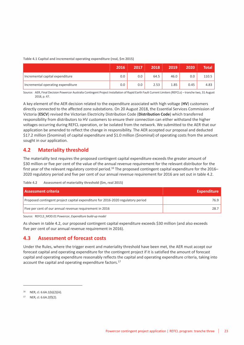
Table 4.1 Capital and incremental operating expenditure (real, $m 2015)
2016 2017 2018 2019 2020 Total
Incremental capital expenditure 0.0 0.0 64.5 46.0 0.0 110.5
Incremental operating expenditure 0.0 0.0 2.53 1.85 0.45 4.83
Source: AER, Final Decision Powercor Australia Contingent Project Installation of Rapid Earth Fault Current Limiters (REFCLs) – tranche two, 31 August 2018, p. 47.
A key element of the AER decision related to the expenditure associated with high voltage (HV) customers directly connected to the affected zone substations. On 20 August 2018, the Essential Services Commission of Victoria (ESCV) revised the Victorian Electricity Distribution Code (Distribution Code) which transferred responsibility from distributors to HV customers to ensure their connection can either withstand the higher voltages occurring during REFCL operation, or be isolated from the network. We submitted to the AER that our application be amended to reflect the change in responsibility. The AER accepted our proposal and deducted $17.2 million ($nominal) of capital expenditure and $1.0 million ($nominal) of operating costs from the amount sought in our application.
4.2 Materiality threshold
The materiality test requires the proposed contingent capital expenditure exceeds the greater amount of $30 million or five per cent of the value of the annual revenue requirement for the relevant distributor for the first year of the relevant regulatory control period.16 The proposed contingent capital expenditure for the 2016–2020 regulatory period and five per cent of our annual revenue requirement for 2016 are set out in table 4.2.
Table 4.2 Assessment of materiality threshold ($m, real 2015)
Assessment criteria Expenditure
Proposed contingent project capital expenditure for 2016-2020 regulatory period 76.9
Five per cent of our annual revenue requirement in 2016 28.7
Source: REFCL3_MOD.01 Powercor, Expenditure build-up model
As shown in table 4.2, our proposed contingent capital expenditure exceeds $30 million (and also exceeds five per cent of our annual revenue requirement in 2016).
4.3 Assessment of forecast costs
Under the Rules, where the trigger event and materiality threshold have been met, the AER must accept our forecast capital and operating expenditure for the contingent project if it is satisfied the amount of forecast capital and operating expenditure reasonably reflects the capital and operating expenditure criteria, taking into account the capital and operating expenditure factors.17
16 NER, cl. 6.6A.1(b)(2)(iii). 17 NER, cl. 6.6A.2(f)(2).
24 Powercor contingent project application | REFCL program: tranche three
The capital expenditure criteria requires the total capital expenditure forecast reasonably reflects a realistic expectation of the demand forecast and cost inputs required to achieve the capital expenditure objectives.18
The capital expenditure objectives includes the total forecast expenditure required to comply with all applicable regulatory obligations or requirements associated with the provision of standard control services, or where there is no applicable obligation, to maintain the quality, reliability and security of supply of standard control services, and the safety of the distribution system through the supply of standard control services.19
We note that this application covers the period 2019 to 2026, i.e. the first and second regulatory periods. The contingent project mechanism was designed to accommodate large projects that traverse regulatory periods.20 Any unspent capital expenditure approved by the AER through this application will be included in our regulatory proposal for the 2021–2026 regulatory period.
18 NER, cl. 6.5.7(c)(3). 19 NER, cl. 6.5.7(a). 20 NER, cl. 6.5.7(f).
5Key differences from tranche two

26 Powercor contingent project application | REFCL program: tranche three
This page is intentionally blank.
Powercor contingent project application | REFCL program: tranche three 27
There are several key differences between this contingent project application and our second application. This application covers different geographical areas of our network, with consequential changes to the infrastructure and network characteristics and requirements.
Some processes and costs have also changed since our first application.
The primary differences are driven by our learnings from our REFCL deployment program so far. Our tranche one application was submitted in March 2017 where the scope and cost estimates were based on our REFCL trials at Woodend and Gisborne. At that time, only the REFCL at Gisborne zone substation was in service and only a limited amount of actual information was available for scoping and estimating.
Our tranche two application was lodged in March 2018. The approach was largely unchanged from tranche one, as no REFCLs were commissioned in 2017. The few changes made, such as balancing methodology, cable and current transformer replacements, and use of earth grids was based on the construction that had occurred to date for tranche one sites.
Since our tranche two application was submitted, we have commissioned and put into service eight tranche one zone substations with three tranche two zone substations in construction. We have a much greater amount of actual data, detailed information and costs upon which to base this application. Of the seven zone substations that have been tested for performance, ESV has also only provided conditional acceptance that we have meet those requirements.
The key differences between this application and tranche two relate to:
• network characteristics
• zone substation requirements
• HV customers
• approach to forecasting balancing requirements
• asset resilience testing
• increasing material costs from suppliers
• testing trailers
• spare parts.
We discuss each of these matters below.
5.1 Network characteristics
Our tranche three application relates to the installation of REFCLs in seven zone substations in our network. Five of the seven zone substations covered by this application are located in regional and rural areas of western and south western Victoria.
The Ararat (ART), Hamilton (HTN), Koroit (KRT), Stawell (STL) and Terang (TRG) zone substations serve the regional towns as well as the surrounding rural areas. Aside from HTN, they each serve less than 10,000 customers.
HTN zone substation serves over 13,000 customers, and has the most customers of any zone substation in this application. It is the only zone substation in this application requiring more than one REFCL.
The Merbein (MBN, near Mildura) and Corio (CRO, near Geelong) zone substations are in more industrialised areas. MBN serves the town of Merbein, an irrigation area and the surrounding rural areas. CRO is located in the
5 Key differences from tranche one
28 Powercor contingent project application | REFCL program: tranche three
North Shore industrial area and supplies the heavy industrial area around the Port of Geelong. These zone substations each serve over 10,000 customers.
The remote locations in this application drive an increase in the number of labour hours to undertake works compared with tranche two given the increase in travel time. Additionally, the HTN, KRT and TRG zone substations cover areas with volcanic rock, which presents challenges in achieving a safe and effective earthing of capacitive balancing units and test sites.
5.2 Zone substation requirements
Four of the seven zone substations in this application are space constrained. They do not have sufficient space to install the REFCL, neutral bus and other associated equipment.
Redevelopment of these space constrained zone substations is required:
• Corio (CRO) zone substation needs a new control room with new protection relays
• HTN (HTN) zone substation needs a new control room with new protection relays, and a new switchroom with new circuit breakers
• Stawell (STL) zone substation needs a new control room with new protection relays
• Terang (TRG) requires the purchase of adjacent land to expand the zone substation footprint. Redevelopment of the zone substation is required to construct a new control room with new protection relays, and new switchroom with new circuit breakers.
Each redevelopment must be carefully designed and managed with multiple stages of work to ensure that the station remains on supply. This will entail temporary primary construction, temporary secondary and protection/control construction. Extensive civil works will be required for these zone substation redevelopments.
The installation of a REFCL at a zone substation can impact other parts of the Powercor distribution network. Generally, the REFCL would only impact the 22kV HV feeders directly connected to the REFCL zone substation. During contingent events, however, the open points on the network may change resulting in feeders connected to other zone substations being served from a REFCL zone substation and thus experiencing the higher voltages associated with the operation of a REFCL. Therefore, works undertaken to harden a particular zone substation may require that feeders from other non-REFCL zone substations also need to be hardened. Consistent with our approach in tranche one and tranche two, in this application:
• CRO requires hardening on some Ford North Shore and Geelong B feeders
• KRT requires hardening on some feeders from Warrnambool zone substation
• Merbein requires hardening on some feeders from Mildura zone substation
• STL requires hardening works on some feeders from Horsham zone substation
• TRG requires hardening works on some feeders from Cobden zone substation.
5.3 HV customers
On 20 August 2018, the ESCV revision of the Distribution Code transferred responsibility from distributors to HV customers to ensure their connection can either withstand the higher voltages occurring during REFCL operation, or be isolated from the network.
The change in responsibility means that we are not seeking costs to install isolation substations at customer sites, or payments to HV customers to harden their network in exchange for their agreement to a change in our obligations under the Distribution Code.
Powercor contingent project application | REFCL program: tranche three 29
However, we will seek costs relating to those customers to integrated modified HV customer installations into our network, in particular:
• installation of Automatic Circuit Reclosers (ACRs) at all HV customer sites
• installation of neutral displacement protection coordination equipment for generator HV customers
• costs for Powercor to independently verify third party reports that HV customers are appropriately hardened or able to be isolated from our network during the operation of a REFCL.
First, we need to install ACRs at all HV customer connection points to ensure that we can isolate the customer and protect our network, particularly in the event of a cross-country fault. The ACRs will also ensure that we can maintain phase-to-phase voltages across our network.
Second, we need to install neutral displacement protection coordination equipment for our HV customers that have generation facilities. This relates to two sites in tranche two.
When generators connect to our network, we require them to install neutral displacement protection equipment. This scheme is designed to protect the 22kV network from earth faults supplied by the generator in the event of an inadvertent islanding event. For example, if there is a fault on the line and Powercor’s protection operates resulting in the circuit breaker tripping the feeder, their generators may continue to operate in an islanded mode with the earth fault continuing to exist. Neutral displacement protection detects this, however the protection will maloperate every time the REFCL operates, as experienced by HV customers connected to other distributor’s REFCL zone substations. As we require the customer to install this protection, we will provide a signal to co-ordinate their protection with the REFCL operation.
The neutral displacement protection co-ordination will require a protection relay, batteries and communications equipment which can all be housed in a cubicle. Our costs for these are based on similar interconnection works at small generation sites.
Finally, we have included costs for consulting engineers to assess each HV customer’s hardening works as well as stakeholder engagement costs for each HV customer to support them in understanding REFCL technology and the impact on them and their assets.
5.4 Balancing units
Our approach to designing and forecasting our requirements for balancing the network has been revised following our experience during the tranche one deployment program.
Each feeder on our network is segmented into isolatable sections, which are determined by the existence of remote controlled devices. A balancing unit is included in each segment, which may be at an Automatic Circuit Recloser (ACR) or a gas switch. To maintain a well-balanced network we need the network balancing assets to be adjustable and to allow for the operation of equipment such as ACRs and fuses. Remote controlled devices, such as three-phase balancing units, are dynamic and enable faster restoration following a fault.
We have carried out detailed field verification audits to confirm the phasing of powerlines and confirmation of each network device used to isolate sections of the network. This has then been modelled through the power flow analysis tool called Power Systems Simulator Sincal (PSS Sincal) to accurately design our network and inform our balancing requirements. The available options for network balancing are:
• install single-phase capacitive balancing units on single-phase network spurs and/or single-phase underground cable
• install three-phase capacitive balancing units between remote-controlled switching sections, as well as between strategically located manually-operated isolatable sections
30 Powercor contingent project application | REFCL program: tranche three
• perform overhead re-phasing works to cater for single-phase overhead line
• install a third-phase of overhead conductor rather than a single-phase capacitive balancing unit to particular single-phase (two wire) lines to maintain operability of the network
• install fuse savers for any fused sections where required on overhead line and underground cable
• upgrade HV regulators to closed delta configurations with parallel control.
Single-phase balancing units and line rephasing delivers fixed levels of capacitance. The switching sections are therefore balanced for the static configuration of the network and do not allow for rebalancing of the feeder following a fault using both manual switches and remote controlled devices. Compared to tranche two, tranche three has more lengthy single-phase spurs driving a greater number of units. The installation of single-phase balancing units has taken longer in practice than previously estimated, thereby increasing the labour cost component of each unit.
Three-phase balancing units allow tuning of the level of supplementary capacitance provided for each section of the feeder, and can be remote controlled. The dynamic feature of three phase balancing unit provides greater network flexibility for minor customer-driven augmentation as well as balancing and faster restoration following a fault. These units enable us to rebalance the feeder following faults where the feeder is partially restored using manual switches.
In limited cases, we will install the third phase of a single phase (two wire) line which provides a better engineering outcome through a greater ability to switch and operate the network in a safe and reliable manner. Through our experience with tranche one, we have found that installing the third phase is the only available option due to physical constraints at that location.
5.5 Asset resilience testing
We have commenced a program to test the ability of our distribution assets to be compatible with the operation of a REFCL prior to deployment. Where an asset fails the resilience testing, we will assess whether repairs can be undertaken or whether replacement of the asset is required.
Distribution switchgear installed throughout our network provides the functionality to reconfigure our network for operational requirements, fault response, and general maintenance. The failure of distribution switchgear will result in feeder faults and corresponding wide-spread outages.
Prior to our network stress testing and commissioning processes at GSB and WND, we undertook resilience assessments on selected distribution plant assets (typically older assets with a heightened risk of failure). For our FG switchgear, this assessment was to ensure these assets could withstand elevated voltages up to 24kV for a period of 30 minutes. The resilience assessment of our FG switchgear confirmed a limitation of 20.8kV—that is, the FG switchgear was unable to meet the required elevated voltages (let alone withstand these voltages for a period of 30 minutes).
The failure of the FG switchgear cannot be addressed by modification or maintenance to the asset as the failure is due to inherent design and construction factors—these units are hermetically sealed SF6 pressurised welded tanks. The only technically feasible option, therefore, is the replacement of these assets.
As part of our asset resilience testing approach for distribution switchgear in tranche one, we also performed partial discharge monitoring. At our tranche one sites, we have found high levels of partial discharge across the ABB fleet of switchgear during off-line testing. Additionally, an ABB ring-main-unit catastrophically failed during stress testing at Colac (CLC) zone substation. The ABB switchgear is unsuitable to operate on REFCL networks.
For tranche one, 6 per cent of other distribution switchgear (i.e. other than ABB and F&G) failed the resilience testing, and required replacement.
Powercor contingent project application | REFCL program: tranche three 31
Based on our tranche one experience, we will replace 100% of the ABB and F&G switchgear as well as 6 per cent of all other distribution switchgear.
5.6 Increased material costs from suppliers
Based on actual invoices for tranche two sites, the material unit costs for the following items have increased:
• switchrooms
• station service transformers
• gas switch control boxes
• single-phase capacitive balancing units.
The higher material costs are reflected in our unit costs for each item.
5.7 Testing trailer
We have included costs for two new testing trailers in this application. Tranche three contains remote sites meaning that long travel distances are required to complete the commissioning and ESV-observed compliance testing for each zone substation.
The testing trailers purchased for tranches one and two will still be in use for commissioning activities for tranche two as well as annual testing of the REFCLs in service. Furthermore, each test trailer must undergo maintenance and servicing twice a year, where they are unable to be used.
5.8 Spare GFN
We have included within this application costs for a spare GFN, associated labour and re-commissioning costs, to be used if another GFN fails. The long lead times for procurement of a GFN support holding a spare as part of our asset management strategy. Should a GFN fail during the testing and commissioning phase, or when in-service, then the spare can be utilised to ensure that we meet our obligations as set out in the Amended Bushfire Mitigation Regulations, and are able to continue to operate the network in a safe and reliable manner. By the end of tranche three, we will have 34 GFNs in operation.

32 Powercor contingent project application | REFCL program: tranche three
This page is intentionally blank.
6Forecast expenditure

34 Powercor contingent project application | REFCL program: tranche three
This page is intentionally blank.
Powercor contingent project application | REFCL program: tranche three 35
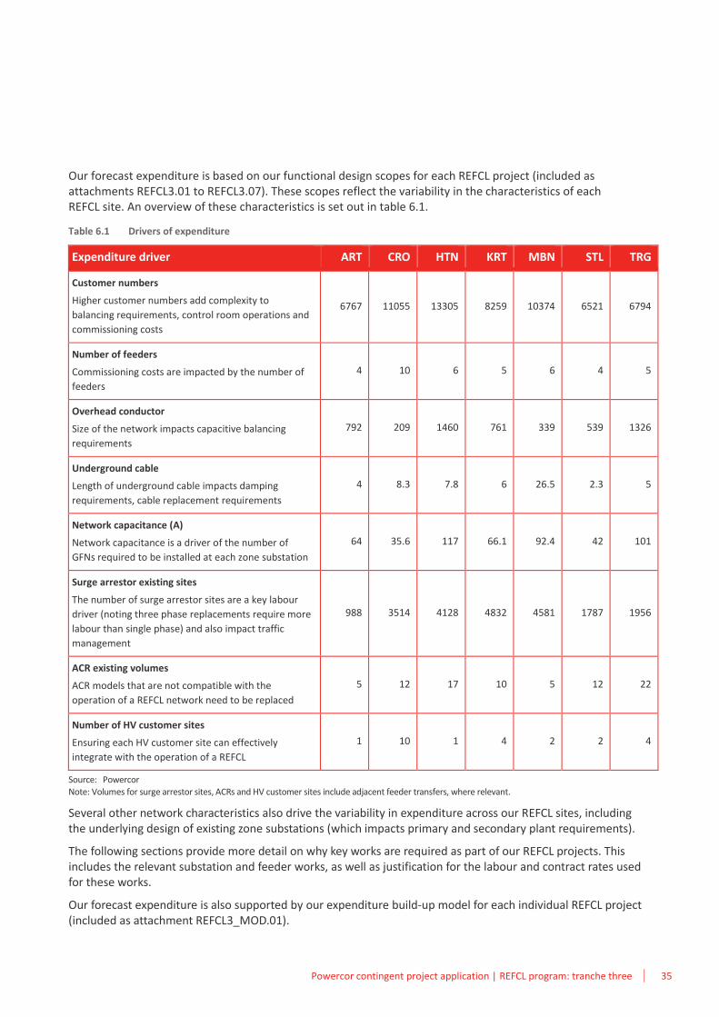
Our forecast expenditure is based on our functional design scopes for each REFCL project (included as attachments REFCL3.01 to REFCL3.07). These scopes reflect the variability in the characteristics of each REFCL site. An overview of these characteristics is set out in table 6.1.
Table 6.1 Drivers of expenditure
Expenditure driver ART CRO HTN KRT MBN STL TRG
Customer numbers
Higher customer numbers add complexity to
balancing requirements, control room operations and
commissioning costs
6767 11055 13305 8259 10374 6521 6794
Number of feeders
Commissioning costs are impacted by the number of
feeders
4 10 6 5 6 4 5
Overhead conductor
Size of the network impacts capacitive balancing
requirements
792 209 1460 761 339 539 1326
Underground cable
Length of underground cable impacts damping
requirements, cable replacement requirements
4 8.3 7.8 6 26.5 2.3 5
Network capacitance (A)
Network capacitance is a driver of the number of
GFNs required to be installed at each zone substation
64 35.6 117 66.1 92.4 42 101
Surge arrestor existing sites
The number of surge arrestor sites are a key labour
driver (noting three phase replacements require more
labour than single phase) and also impact traffic
management
988 3514 4128 4832 4581 1787 1956
ACR existing volumes
ACR models that are not compatible with the
operation of a REFCL network need to be replaced
5 12 17 10 5 12 22
Number of HV customer sites
Ensuring each HV customer site can effectively
integrate with the operation of a REFCL
1 10 1 4 2 2 4
Source: Powercor
Note: Volumes for surge arrestor sites, ACRs and HV customer sites include adjacent feeder transfers, where relevant.
Several other network characteristics also drive the variability in expenditure across our REFCL sites, including the underlying design of existing zone substations (which impacts primary and secondary plant requirements).
The following sections provide more detail on why key works are required as part of our REFCL projects. This includes the relevant substation and feeder works, as well as justification for the labour and contract rates used for these works.
Our forecast expenditure is also supported by our expenditure build-up model for each individual REFCL project (included as attachment REFCL3_MOD.01).
6 Forecast expenditure
36 Powercor contingent project application | REFCL program: tranche three
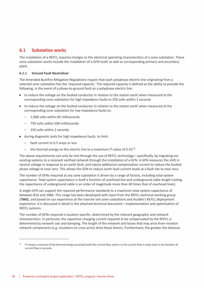
6.1 Substation works
The installation of a REFCL requires changes to the electrical operating characteristics of a zone substation. These zone substation works include the installation of a GFN itself, as well as corresponding primary and secondary plant.
6.1.1 Ground Fault Neutraliser
The Amended Bushfire Mitigation Regulations require that each polyphase electric line originating from a selected zone substation has the 'required capacity'. The required capacity is defined as the ability to provide the following, in the event of a phase-to-ground fault on a polyphase electric line:
• to reduce the voltage on the faulted conductor in relation to the station earth when measured at the corresponding zone substation for high impedance faults to 250 volts within 2 seconds
• to reduce the voltage on the faulted conductor in relation to the station earth when measured at the corresponding zone substation for low impedance faults to:
– 1,900 volts within 85 milliseconds
– 750 volts within 500 milliseconds
– 250 volts within 2 seconds
• during diagnostic tests for high impedance faults, to limit:
– fault current to 0.5 amps or less
– the thermal energy on the electric line to a maximum I2t value of 0.10.21
The above requirements can only be met through the use of REFCL technology—specifically, by migrating our existing systems to a resonant earthed network through the installation of a GFN. A GFN measures the shift in neutral voltage in response to an earth fault, and injects additional compensation current to reduce the faulted phase voltage to near zero. This allows the GFN to reduce earth fault current levels at a fault site to near zero.
The number of GFNs required at any zone substation is driven by a range of factors, including total system capacitance. Total system capacitance is itself a function of overhead line and underground cable length (noting the capacitance of underground cable is an order of magnitude more than 40 times that of overhead lines).
A single GFN can support the required performance standards to a maximum total system capacitance of between 81A and 108A. This range has been developed with input from the REFCL technical working group (TWG), and based on our experience at the tranche one zone substations and AusNet's REFCL deployment experience. It is discussed in detail in the attached technical document—implementation and optimisation of REFCL systems.
The number of GFNs required is location-specific, determined by the relevant geographic and network characteristics. In particular, the capacitive charging current required to be compensated by the REFCL is determined by network size and damping. The length of the network and losses that may arise from resistive network components (e.g. insulators on cross arms) drive these factors. Furthermore, the greater the distance
21 I2t means a measure of the thermal energy associated with the current flow, where I is the current flow in amps and t is the duration of current flow in seconds.
Powercor contingent project application | REFCL program: tranche three 37
from the zone substation to any underground cable increases the damping and thus total charging current requirements for a particular zone substation.
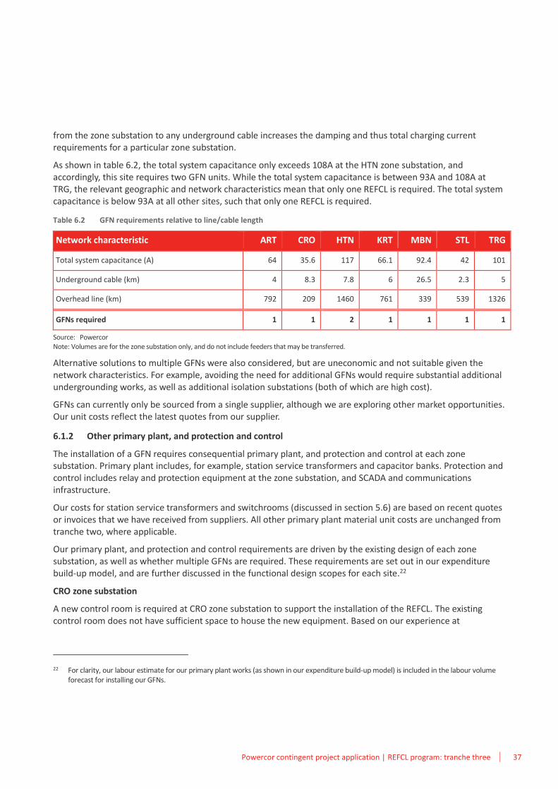
As shown in table 6.2, the total system capacitance only exceeds 108A at the HTN zone substation, and accordingly, this site requires two GFN units. While the total system capacitance is between 93A and 108A at TRG, the relevant geographic and network characteristics mean that only one REFCL is required. The total system capacitance is below 93A at all other sites, such that only one REFCL is required.
Table 6.2 GFN requirements relative to line/cable length
Network characteristic ART CRO HTN KRT MBN STL TRG
Total system capacitance (A) 64 35.6 117 66.1 92.4 42 101
Underground cable (km) 4 8.3 7.8 6 26.5 2.3 5
Overhead line (km) 792 209 1460 761 339 539 1326
GFNs required 1 1 2 1 1 1 1
Source: Powercor Note: Volumes are for the zone substation only, and do not include feeders that may be transferred.
Alternative solutions to multiple GFNs were also considered, but are uneconomic and not suitable given the network characteristics. For example, avoiding the need for additional GFNs would require substantial additional undergrounding works, as well as additional isolation substations (both of which are high cost).
GFNs can currently only be sourced from a single supplier, although we are exploring other market opportunities. Our unit costs reflect the latest quotes from our supplier.
6.1.2 Other primary plant, and protection and control
The installation of a GFN requires consequential primary plant, and protection and control at each zone substation. Primary plant includes, for example, station service transformers and capacitor banks. Protection and control includes relay and protection equipment at the zone substation, and SCADA and communications infrastructure.
Our costs for station service transformers and switchrooms (discussed in section 5.6) are based on recent quotes or invoices that we have received from suppliers. All other primary plant material unit costs are unchanged from tranche two, where applicable.
Our primary plant, and protection and control requirements are driven by the existing design of each zone substation, as well as whether multiple GFNs are required. These requirements are set out in our expenditure build-up model, and are further discussed in the functional design scopes for each site.22
CRO zone substation
A new control room is required at CRO zone substation to support the installation of the REFCL. The existing control room does not have sufficient space to house the new equipment. Based on our experience at
22 For clarity, our labour estimate for our primary plant works (as shown in our expenditure build-up model) is included in the labour volume forecast for installing our GFNs.
38 Powercor contingent project application | REFCL program: tranche three
Maryborough (MRO) and Charlton (CTN) zone substations, extensive civil works would be required to renovate the existing ageing and asbestos-ridden building which would still be space-constrained.
The new control room would house new feeder protection relays, transformer differential relays, 22kV circuit breaker management relays, station earth fault management, neutral bus management, digital fault record, ethernet switches, ethernet firewall as well as the REFCL cubicle itself.
The large number of aged electromechanical relays at CRO would also be replaced for the new control room. Therefore, a careful and staged approach to constructing the new control room will be required while the CRO zone substation continues to operate.
Co-location of the REFCL and associated equipment with the transformers at the zone substation is the most practical and efficient approach to introducing the resonant network. Housing the REFCL and associated equipment at a separate location may result in inefficient cable relocations and/or separate REFCLs for each zone substation feeder, as well as pose operational hazards and restrictions.
HTN zone substation
A new control room is required at HTN zone substation to support the installation of the REFCL. The current zone substation in in banked formation, and heavily space constrained with insufficient space to house the new REFCL equipment.
A complex redevelopment of the HTN zone substation is required to install the REFCL. The existing outdoor 22kV yard arrangement does not allow for the installation of 22kV circuit breakers, which are required when installing multiple GFN units.
The redevelopment will entail multiple stages of work and temporary rearrangements of the zone substation to transfer load. The capacitors must be replaced in a new location within the zone substation. This provides space for the installation of a 22kV switchroom and switchboard. Subsequently, the existing 22kV bus will be retired which will create space for the REFCL and associated neutral bus and station service transformers.
The redevelopment will entail conductor relocations and other temporary primary construction, temporary secondary and protection/control construction and commissioning. These temporary arrangements will require remote end works for back bone feeders e.g. open points and protection and control schemes.
Modification to the earth grid is also required at HTN as the zone substation contains multiple GFN units.
Co-location of the REFCL and associated equipment with the transformers at the zone substation is the most practical and efficient approach to introducing the resonant network. Housing the REFCL and associated equipment at a separate location may result in inefficient cable relocations and/or separate REFCLs for each zone substation feeder, as well as pose operational hazards and restrictions.
STL zone substation
A new control room is required at STL zone substation to support the installation of the REFCL. The existing control room does not have sufficient space to house the new equipment. Based on our experience at Maryborough (MRO) and Charlton (CTN) zone substations, extensive civil works would be required to renovate the existing ageing and asbestos-ridden building which would still be space-constrained.
The new control room would house new feeder protection relays, transformer differential relays, 22kV circuit breaker management relays, station earth fault management, neutral bus management, digital fault record, ethernet switches, ethernet firewall as well as the REFCL cubicle itself.
Co-location of the REFCL and associated equipment with the transformers at the zone substation is the most practical and efficient approach to introducing the resonant network. Housing the REFCL and associated
Powercor contingent project application | REFCL program: tranche three 39
equipment at a separate location may result in inefficient cable relocations and/or separate REFCLs for each zone substation feeder, as well as pose operational hazards and restrictions.
TRG zone substation
A new control room and switch room is required at an expanded TRG zone substation site. The existing TRG site is space constrained and additional land must be purchased to house the new REFCL equipment. A new 22kV indoor switchroom and switchboard is required as there is insufficient space to install current transformers on the HV feeders emanating from the zone substation without a full reconstruction of the 22kV outdoor bus.
Co-location of the REFCL and associated equipment with the transformers at the zone substation is the most practical and efficient approach to introducing the resonant network. Housing the REFCL and associated equipment at a separate location may result in inefficient cable relocations and/or separate REFCLs for each zone substation feeder, as well as pose operational hazards and restrictions.
6.2 Feeder works
Our feeder works reflect network hardening and compatibility expenditure to replace any assets on our network that are expected to fail or malfunction under the operation of a REFCL. This expenditure includes the following:
• surge arrestor replacements
• ACR replacements
• capacitive balancing requirements
• distribution switchgear replacements
• HV cable replacements.
We have also included costs associated with HV customers for the purposes of maintaining a safe and reliable network.
6.2.1 Surge arrestor replacement program
For an earth fault on a resonant network, full voltage displacement of healthy phases occurs on a system wide scale. Full voltage displacement, irrespective of the time period, may result in voltage levels that exceed the notional capacity of our existing surge arrestors. For example, many of our existing surge arrestors have a maximum continuous operating voltage of 20kV, with limited temporary over-voltage capacity. During REFCL operation, the full phase-to-ground voltage is elevated up to 24.2kV for periods in excess of 30 seconds.
The failure of a surge arrestor to withstand over-voltages arising from the operation of a REFCL could induce a cross-country fault on the distribution system. This will result in multiple feeder outages, and potential fire starts.
Our existing fleet of surge arrestors includes a range of brands and in turn, a variety of models. The replacement of all surge arrestors on feeders served by a zone substation where a REFCL is being installed represents a significant cost. Our REFCL project, therefore, proposes to only replace surge arrestors with known operating characteristics that are not compatible with REFCL installations will be replaced (i.e. if the rated voltage is less than 24.2kV).
Consistent with tranche one, and as set out in GHD's final report, we found only the following types of surge arrestor installed on our network are capable of withstanding the higher voltages expected during the operation of a REFCL:
• type A: Bowthorpe porcelain silicon carbide (22kV and 24kV)
• type W: ABB polim D polymeric zinc oxide, class A 22kV.
40 Powercor contingent project application | REFCL program: tranche three
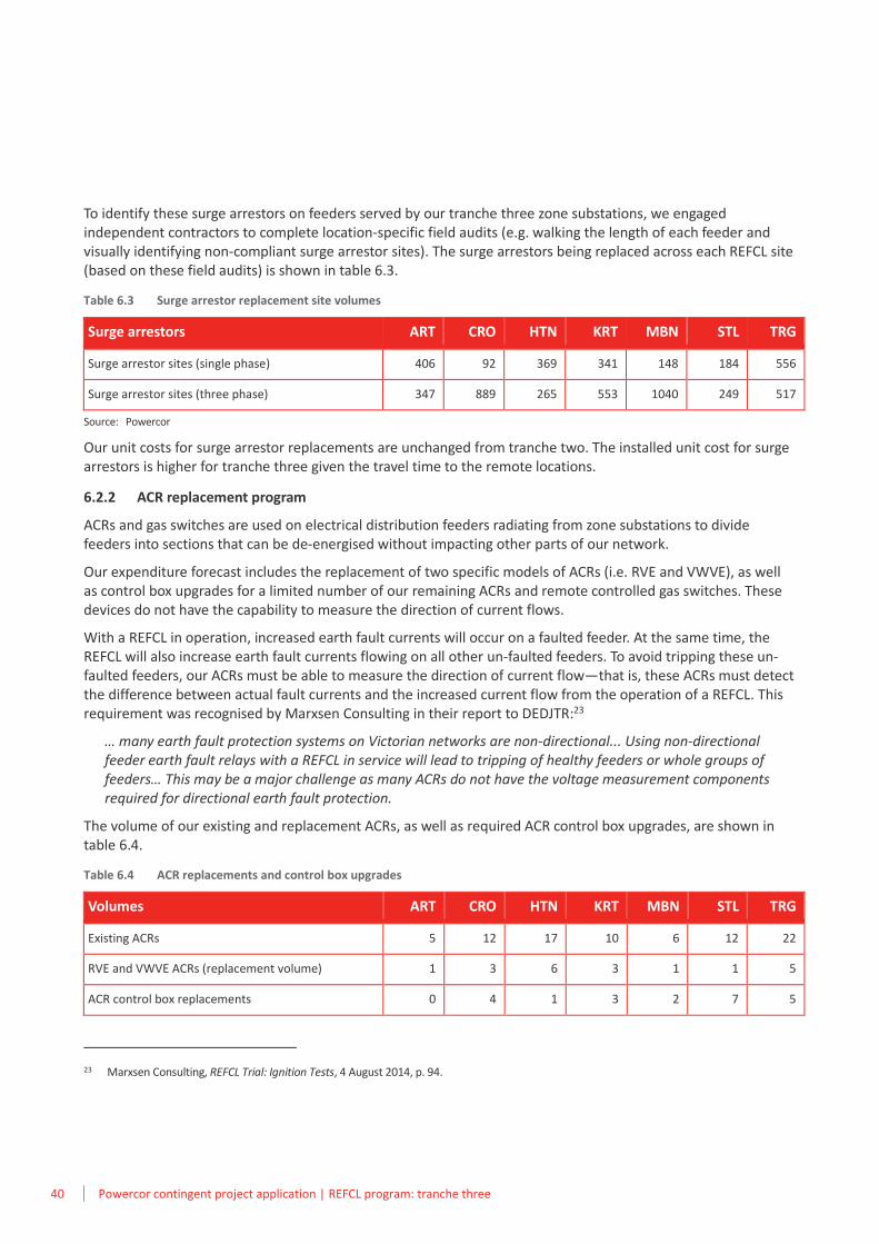
To identify these surge arrestors on feeders served by our tranche three zone substations, we engaged independent contractors to complete location-specific field audits (e.g. walking the length of each feeder and visually identifying non-compliant surge arrestor sites). The surge arrestors being replaced across each REFCL site (based on these field audits) is shown in table 6.3.
Table 6.3 Surge arrestor replacement site volumes
Surge arrestors ART CRO HTN KRT MBN STL TRG
Surge arrestor sites (single phase) 406 92 369 341 148 184 556
Surge arrestor sites (three phase) 347 889 265 553 1040 249 517
Source: Powercor
Our unit costs for surge arrestor replacements are unchanged from tranche two. The installed unit cost for surge arrestors is higher for tranche three given the travel time to the remote locations.
6.2.2 ACR replacement program
ACRs and gas switches are used on electrical distribution feeders radiating from zone substations to divide feeders into sections that can be de-energised without impacting other parts of our network.
Our expenditure forecast includes the replacement of two specific models of ACRs (i.e. RVE and VWVE), as well as control box upgrades for a limited number of our remaining ACRs and remote controlled gas switches. These devices do not have the capability to measure the direction of current flows.
With a REFCL in operation, increased earth fault currents will occur on a faulted feeder. At the same time, the REFCL will also increase earth fault currents flowing on all other un-faulted feeders. To avoid tripping these un-faulted feeders, our ACRs must be able to measure the direction of current flow—that is, these ACRs must detect the difference between actual fault currents and the increased current flow from the operation of a REFCL. This requirement was recognised by Marxsen Consulting in their report to DEDJTR:23
… many earth fault protection systems on Victorian networks are non-directional... Using non-directional feeder earth fault relays with a REFCL in service will lead to tripping of healthy feeders or whole groups of feeders… This may be a major challenge as many ACRs do not have the voltage measurement components required for directional earth fault protection.
The volume of our existing and replacement ACRs, as well as required ACR control box upgrades, are shown in table 6.4.
Table 6.4 ACR replacements and control box upgrades
Volumes ART CRO HTN KRT MBN STL TRG
Existing ACRs 5 12 17 10 6 12 22
RVE and VWVE ACRs (replacement volume) 1 3 6 3 1 1 5
ACR control box replacements 0 4 1 3 2 7 5
23 Marxsen Consulting, REFCL Trial: Ignition Tests, 4 August 2014, p. 94.
Powercor contingent project application | REFCL program: tranche three 41
As noted in section 5.6, our material unit costs for gas switch control boxes are higher than tranche two. The ACR replacement material costs are unchanged from tranche two. The installed unit costs for these items is higher for tranche three given the travel time to the remote locations.
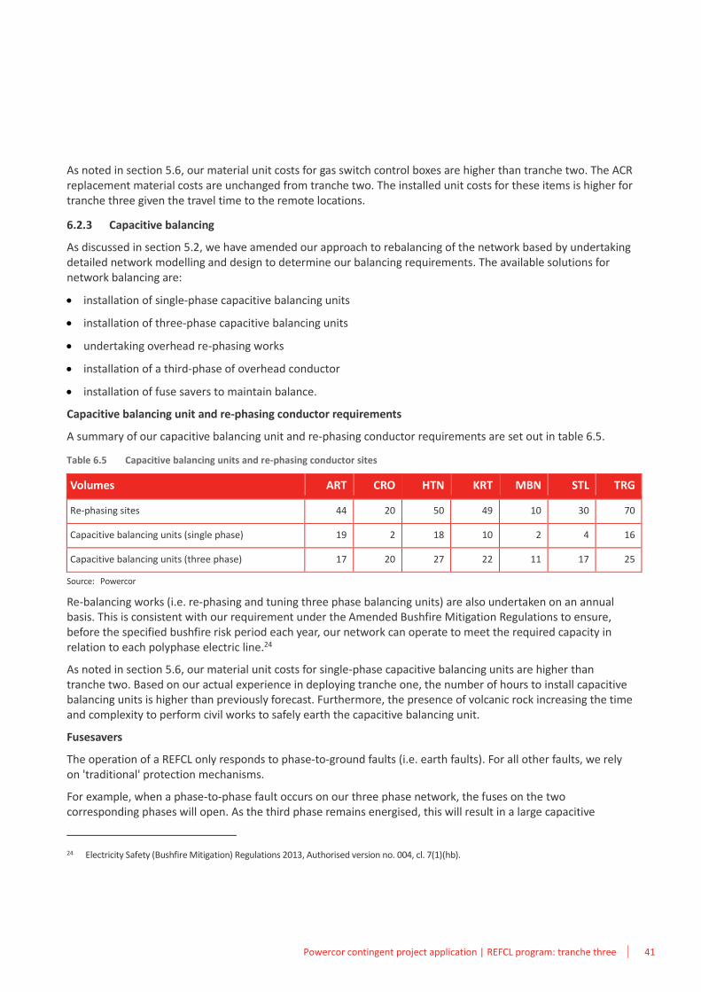
6.2.3 Capacitive balancing
As discussed in section 5.2, we have amended our approach to rebalancing of the network based by undertaking detailed network modelling and design to determine our balancing requirements. The available solutions for network balancing are:
• installation of single-phase capacitive balancing units
• installation of three-phase capacitive balancing units
• undertaking overhead re-phasing works
• installation of a third-phase of overhead conductor
• installation of fuse savers to maintain balance.
Capacitive balancing unit and re-phasing conductor requirements
A summary of our capacitive balancing unit and re-phasing conductor requirements are set out in table 6.5.
Table 6.5 Capacitive balancing units and re-phasing conductor sites
Volumes ART CRO HTN KRT MBN STL TRG
Re-phasing sites 44 20 50 49 10 30 70
Capacitive balancing units (single phase) 19 2 18 10 2 4 16
Capacitive balancing units (three phase) 17 20 27 22 11 17 25
Source: Powercor
Re-balancing works (i.e. re-phasing and tuning three phase balancing units) are also undertaken on an annual basis. This is consistent with our requirement under the Amended Bushfire Mitigation Regulations to ensure, before the specified bushfire risk period each year, our network can operate to meet the required capacity in relation to each polyphase electric line.24
As noted in section 5.6, our material unit costs for single-phase capacitive balancing units are higher than tranche two. Based on our actual experience in deploying tranche one, the number of hours to install capacitive balancing units is higher than previously forecast. Furthermore, the presence of volcanic rock increasing the time and complexity to perform civil works to safely earth the capacitive balancing unit.
Fusesavers
The operation of a REFCL only responds to phase-to-ground faults (i.e. earth faults). For all other faults, we rely on 'traditional' protection mechanisms.
For example, when a phase-to-phase fault occurs on our three phase network, the fuses on the two corresponding phases will open. As the third phase remains energised, this will result in a large capacitive
24 Electricity Safety (Bushfire Mitigation) Regulations 2013, Authorised version no. 004, cl. 7(1)(hb).
42 Powercor contingent project application | REFCL program: tranche three
imbalance. In turn, as recognised in the RIS, this capacitive imbalance may trigger fault responses from a REFCL on feeders where a fault does not exist (i.e. 'healthy' feeders).25
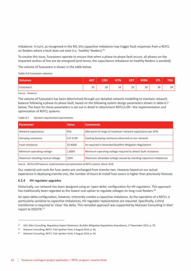
To resolve this issue, fusesavers operate to ensure that when a phase-to-phase fault occurs, all phases on the impacted section of line are de-energised (and hence, the capacitance imbalance on healthy feeders is avoided).
The volume of fusesavers is shown in the table below.
Table 6.6 Fusesaver volumes
Volumes ART CRO HTN KRT MBN STL TRG
Fusesavers 35 18 33 25 18 39 39
Source: Powercor
The volume of fusesavers has been determined through our detailed network modelling to maintain network balance following a phase-to-phase fault, based on the following system design parameters shown in table 6.7 below. The basis for these parameters is set out in detail in attachment REFCL3.09—the implementation and optimisation of REFCL systems.
Table 6.7 System requirement parameters
Parameter Value Comments
Network capacitance 95A Mid-point of range of maximum network capacitance per GFN
Damping resistance 3.0–4.0% Existing damping resistance observed on our network
Fault resistance 25,400Ω As required in Amended Bushfire Mitigation Regulations
Minimum operating voltage 1,600V Minimum operating voltage required to detect fault resistance
Maximum standing neutral voltage 320V Maximum allowable voltage caused by standing capacitive imbalances
Source: REFCL3.09 Powercor, Implementation and optimisation of REFCL systems, March 2018.
Our material unit costs for fuse savers are unchanged from tranche two. However based on our actual experience in deploying tranche one, the number of hours to install fuse savers is higher than previously forecast.
6.2.4 HV regulator upgrades
Historically, our network has been designed using an 'open-delta' configuration for HV regulators. This approach has traditionally been regarded as the lowest cost option to regulate voltages on long rural feeders.26
An open-delta configuration, however, inherently creates a capacitive imbalance. As the operation of a REFCL is particularly sensitive to capacitive imbalances, HV regulator replacements are required. Specifically, a third transformer is required to 'close' the delta. This remedial approach was supported by Marxsen Consulting in their report to DEDJTR.27
25 ACIL Allen Consulting, Regulatory Impact Statement, Bushfire Mitigation Regulations Amendment, 17 November 2015, p. 79. 26 Marxsen Consulting, REFCL Trial: Ignition Tests, 4 August 2014, p. 94. 27 Marxsen Consulting, REFCL Trial: Ignition Tests, 4 August 2014, p. 94.
Powercor contingent project application | REFCL program: tranche three 43
Given the age and condition of our HV regulator fleet, we are replacing these assets as part of our hardening works for the REFCL. In locations where two single phase Cooper HV regulators are installed, we are replacing the assets with three single phase modern Cooper HV regulators. The replacements are usually installed in a physically different location of the network from those which were removed to ensure efficient operation of the network.
We are also upgrading control boxes at existing closed-delta HV regulators (i.e. three phase Cooper HV regulators) to ensure these regulators operate in unison (to prevent capacitive imbalances).
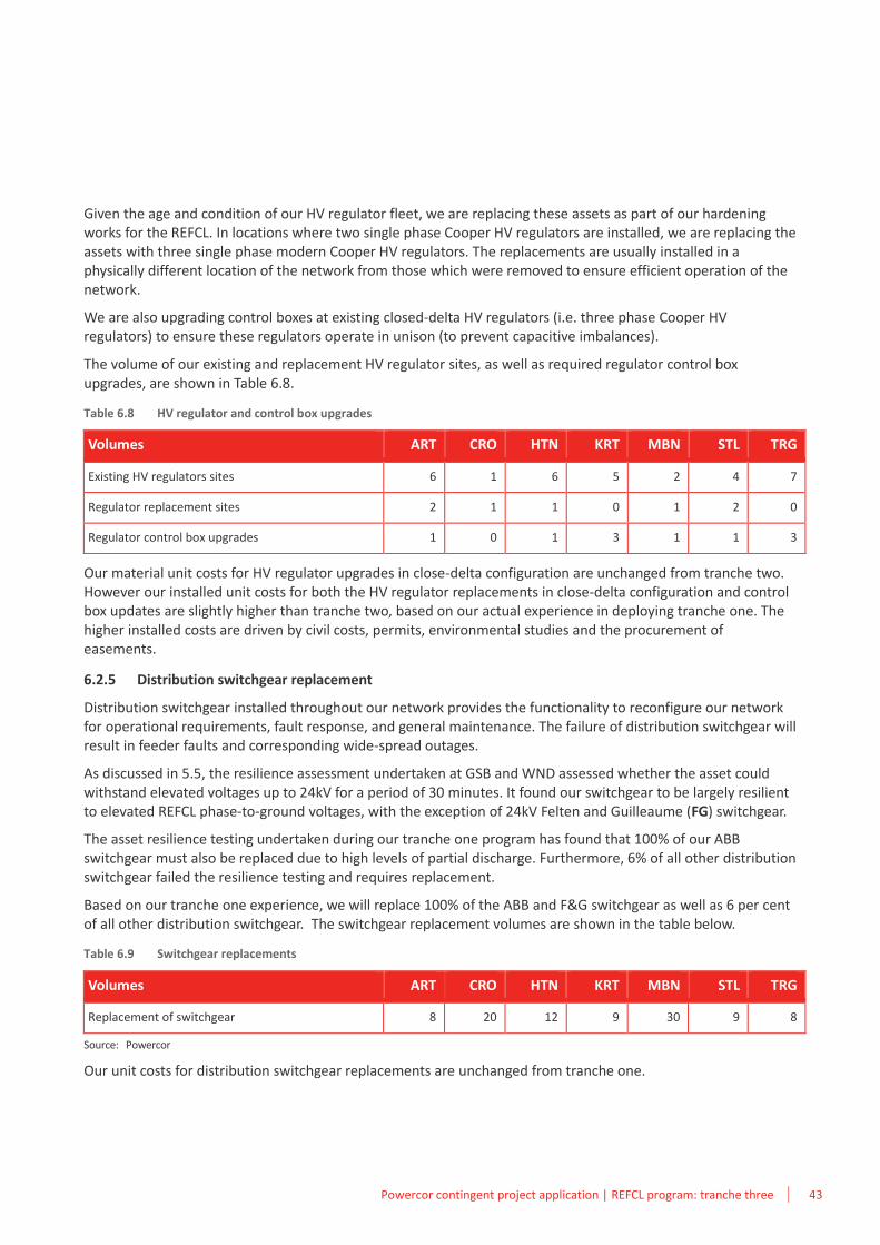
The volume of our existing and replacement HV regulator sites, as well as required regulator control box upgrades, are shown in Table 6.8.
Table 6.8 HV regulator and control box upgrades
Volumes ART CRO HTN KRT MBN STL TRG
Existing HV regulators sites 6 1 6 5 2 4 7
Regulator replacement sites 2 1 1 0 1 2 0
Regulator control box upgrades 1 0 1 3 1 1 3
Our material unit costs for HV regulator upgrades in close-delta configuration are unchanged from tranche two. However our installed unit costs for both the HV regulator replacements in close-delta configuration and control box updates are slightly higher than tranche two, based on our actual experience in deploying tranche one. The higher installed costs are driven by civil costs, permits, environmental studies and the procurement of easements.
6.2.5 Distribution switchgear replacement
Distribution switchgear installed throughout our network provides the functionality to reconfigure our network for operational requirements, fault response, and general maintenance. The failure of distribution switchgear will result in feeder faults and corresponding wide-spread outages.
As discussed in 5.5, the resilience assessment undertaken at GSB and WND assessed whether the asset could withstand elevated voltages up to 24kV for a period of 30 minutes. It found our switchgear to be largely resilient to elevated REFCL phase-to-ground voltages, with the exception of 24kV Felten and Guilleaume (FG) switchgear.
The asset resilience testing undertaken during our tranche one program has found that 100% of our ABB switchgear must also be replaced due to high levels of partial discharge. Furthermore, 6% of all other distribution switchgear failed the resilience testing and requires replacement.
Based on our tranche one experience, we will replace 100% of the ABB and F&G switchgear as well as 6 per cent of all other distribution switchgear. The switchgear replacement volumes are shown in the table below.
Table 6.9 Switchgear replacements
Volumes ART CRO HTN KRT MBN STL TRG
Replacement of switchgear 8 20 12 9 30 9 8
Source: Powercor
Our unit costs for distribution switchgear replacements are unchanged from tranche one.
44 Powercor contingent project application | REFCL program: tranche three
6.2.6 Cable replacement and reterminations
HV cable is installed throughout our network in a range of different specifications. We propose to undertake a proactive replacement approach for XLPE cable, and a reactive replacement approach for underground HV cable that fails. We also propose to reterminate some cables to evenly distribute capacitance at particular zone substations.
HV cable replacement
HV underground cable is installed throughout our network in a range of different specifications. Failure of the underground cable means that a fault occurs on the network leading to outages and increased bushfire risk.
Based on our experience at WND during commissioning, we intend to proactively replace all XLPE cable located in our tranche three zone substation areas that was installed prior to 1989.
At WND, three feeder exit cables failed following the hardening and commissioning tests and two of these suffered further failures following repair and return to service. The cause of these cable failures was linked to the presence of 'water trees' within the cable. The cable failed prematurely due to water tree growth as a result of transient and sustained over voltages applied through the operation of the REFCL.
The cable failures are consistent with the findings in a report prepared by Dr Tony Marxsen for ESV to examine the factors that may create potential safety risks when HV customer sites are supplied by REFCLs. The report identified the high risk of cable asset failures in its assessment of factors that may create potential safety risks when high voltage (HV) customer sites are supplied by REFCL protected networks.
The risk of failure arose from:
• manufacturing defects and contamination leading to the presence of and growth of water trees
• premature failures due to water tree growth as a result of transient and sustained overvoltages
• existing elevated risk of failure (relative to later types of XLPE cables) due to overvoltage applied during REFCL operation.
Our forecast for underground HV cable replacements reflects replacement of all XLPE installed prior to 1989, testing of the remaining cable (including XLPE post 1989), as well as replacement of a percentage of the remaining cable.
The forecast cost is based on our actual repair costs (on a per metre basis). This has been updated based on our experience in tranche one, and reflects the material cost of the cable and conduit plus civil works and labour for fitting and jointing of the cable.
Feeder exit relocation or replacement
With the exception of ART zone substation, feeder exit cables need to be relocated. To balance the capacitance between our REFCLs at HTN zone substation, which is in banked formation, we need to relocate all feeder exits to the new switchroom. At CRO and KRT, all underground feeder exits require replacement.
New feeder tie
A new feeder tie is to be created in the TRG network to maintain the ability to transfer load. This is due to the replacement of the 22kV bus with a new switchroom.
6.2.7 HV customers
As discussed in section 5.2, the Electricity Distribution Code was amended in 2018 and HV customers are now responsible for ensuring that their assets can either withstand the higher voltages occurring during REFCL operation, or be isolated from the network.
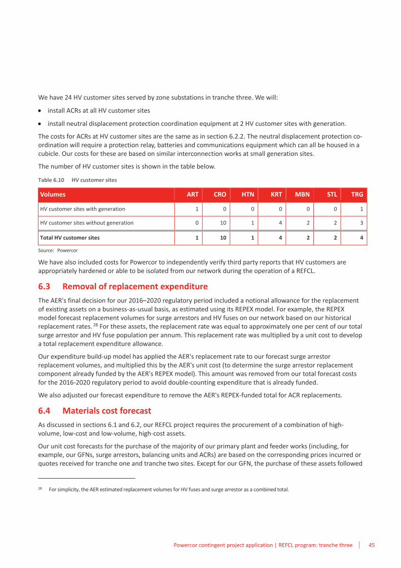
Powercor contingent project application | REFCL program: tranche three 45
We have 24 HV customer sites served by zone substations in tranche three. We will:
• install ACRs at all HV customer sites
• install neutral displacement protection coordination equipment at 2 HV customer sites with generation.
The costs for ACRs at HV customer sites are the same as in section 6.2.2. The neutral displacement protection co-ordination will require a protection relay, batteries and communications equipment which can all be housed in a cubicle. Our costs for these are based on similar interconnection works at small generation sites.
The number of HV customer sites is shown in the table below.
Table 6.10 HV customer sites
Volumes ART CRO HTN KRT MBN STL TRG
HV customer sites with generation 1 0 0 0 0 0 1
HV customer sites without generation 0 10 1 4 2 2 3
Total HV customer sites 1 10 1 4 2 2 4
Source: Powercor
We have also included costs for Powercor to independently verify third party reports that HV customers are appropriately hardened or able to be isolated from our network during the operation of a REFCL.
6.3 Removal of replacement expenditure
The AER's final decision for our 2016–2020 regulatory period included a notional allowance for the replacement of existing assets on a business-as-usual basis, as estimated using its REPEX model. For example, the REPEX model forecast replacement volumes for surge arrestors and HV fuses on our network based on our historical replacement rates. 28 For these assets, the replacement rate was equal to approximately one per cent of our total surge arrestor and HV fuse population per annum. This replacement rate was multiplied by a unit cost to develop a total replacement expenditure allowance.
Our expenditure build-up model has applied the AER's replacement rate to our forecast surge arrestor replacement volumes, and multiplied this by the AER's unit cost (to determine the surge arrestor replacement component already funded by the AER's REPEX model). This amount was removed from our total forecast costs for the 2016-2020 regulatory period to avoid double-counting expenditure that is already funded.
We also adjusted our forecast expenditure to remove the AER's REPEX-funded total for ACR replacements.
6.4 Materials cost forecast
As discussed in sections 6.1 and 6.2, our REFCL project requires the procurement of a combination of high-volume, low-cost and low-volume, high-cost assets.
Our unit cost forecasts for the purchase of the majority of our primary plant and feeder works (including, for example, our GFNs, surge arrestors, balancing units and ACRs) are based on the corresponding prices incurred or quotes received for tranche one and tranche two sites. Except for our GFN, the purchase of these assets followed
28 For simplicity, the AER estimated replacement volumes for HV fuses and surge arrestor as a combined total.
46 Powercor contingent project application | REFCL program: tranche three
our stringent procurement practices. This includes the bulk purchases of equipment (where practicable) and competitive tender processes.
A competitive tender was not undertaken for the purchase of our GFNs, as these units are only manufactured by Swedish Neutral (i.e. a sole supplier). Notwithstanding this, key contractual requirements were agreed to ensure the manufacturer is liable for the stated performance of each unit (e.g. warranty conditions and operational design assurances). Furthermore, we are currently exploring other market opportunities for a second supplier.
The forecast prices for our remaining plant reflect our experience purchasing and installing this equipment in the course of our normal operations, or where applicable, based on the latest costs or quotes from suppliers for tranche one and tranche two sites.
6.5 Labour cost forecast
The key to ensuring labour cost efficiency is the efficient organisation and management of labour to minimise the risk of under-utilisation and under-performance. To achieve optimal labour utilisation, our labour force is structured to provide flexibility in managing labour resources. This includes the following types of labour contracts:
• internal labour—these are permanent employees who provide the base level of labour required to provide a base level of labour services. To operate sustainably over the long term we must ensure we have secure access to a sufficient quantity of labour with the skills and knowledge required to deliver the minimum level of network and corporate services
• local service area (LSA) agents—these are third party owned and operated franchises that provide network services in specific network areas. LSAs service different locations across our network and are generally assigned in the lower density network areas. LSAs are selected through a five yearly market testing process
• resource partners—these are third-party businesses, for example Lend Lease and Electrix, that provide additional labour services on an as needs basis. We utilise our resource partners to manage increased workloads that may arise for specific work programs. Resource partners are identified through a three yearly market testing process
• contractors—we utilise contractors for skill-specific work including electrical work, fault response, metering works, civil works (i.e. digging works), traffic management, design work and vegetation management. We have different contractual arrangements with our contractors, ranging from longer term contracts with third party businesses to project-specific arrangements with individual Registered Electrical Contractors.
We expect to utilise both resource partner and internal labour for the delivery of our REFCL program. The use of each labour source is discussed below.
For the purpose of this contingent project application, we have applied labour escalation for the period to 2020 based on the approach and escalators set out in the AER's final decision for our 2016–2020 regulatory period.
6.5.1 Resource partners
For the following reasons, we expect to utilise labour provided by our external resource partners for the design and delivery of our required substation and feeder works:
• our internal and LSA labour resources are fully utilised on our existing capital program (as set out in our regulatory proposal for the 2016–2020 regulatory period)—this reflects the contingent nature of our REFCL program
• utilising resource partners and external contractors reduces the risk of labour stranding following large-scale or skill-specific projects
Powercor contingent project application | REFCL program: tranche three 47
• our resource partner and external contractor rates are subject to stringent market tender processes. This includes open market offers, followed by qualitative assessments of their ability to perform the required works and quantitative assessments of the tendered rates.
Design
Our design labour rates represent a simple average of rates provided by our design resource partners. As noted above, these rates are the result of an open-market, competitive tender process.
The forecast design hours vary for each REFCL site based on the technical requirements and volumes set out in the individual functional design scopes.
Feeder and substation works
Our feeder and substation labour rates represent a simple average of rates provided by our delivery resource partners. These rates vary by region (e.g. Mildura resource partner rates are used for MBN, Warrnambool rates are used for HTN, KRT and TRG, Horsham rates are used for ART and STL, and Geelong rates are used for CRO). As noted above, these rates are the result of an open-market, competitive tender process.
The forecast feeder and substation hours vary for each REFCL site based on the technical requirements and volumes set out in the individual functional design scopes.
Civil works
We are experiencing higher civil contractor quotes for tranche two sites given the shortage of skilled labour. The shortage results from the multitude of large infrastructure projects being undertaken throughout Victoria.
6.5.2 Internal labour
Our forecast of commissioning works, construction delivery and site control, and our project management office is based on internal resources. The basis for these forecasts is set out below.
Commissioning costs
Commissioning works are required to finalise balancing of the 22kV distribution network, to assess the network compatibility with healthy phase over-voltages, to test and prove all protection schemes associated with the REFCL and to identify the sensitivity capability of the REFCL.
Our commissioning process for each REFCL site begins by following Swedish Neutral's recommended commissioning plan to ensure each unit has been installed, wired and configured as required.
Once these pre-commissioning checks have been completed, we will undertake the following:
• balancing unit tuning—this involves switching the 22kV network and tuning each balancing unit to ensure switching sections are individually balanced. This tuning allows us to increase the REFCL sensitivity so we can ensure we can achieve the required fault resistance of 25,400 ohms
• stress testing—this involves switching on the REFCL and systematically applying over-voltages on each phase of our 22kV network to confirm if the network is appropriately hardened or identify weak or vulnerable equipment
• primary fault testing—this testing uses a portable earth fault testing trailer to test the ability of the REFCL to meet the performance specification in terms of sensitivity and speed of operation. In addition to
48 Powercor contingent project application | REFCL program: tranche three
commissioning, this testing is required to be undertaken annually, consistent with the approach set out in our approved BMP (and required under the Amended Bushfire Mitigation Regulations).29
On rural networks, we usually impose a planned outage to conduct network balancing.
Stress testing of the network involves utilising the Residual Current Compensation (RCC) inverter to artificially elevate the phase-to-earth voltage on each feeder to place the same stress on the network assets as would be experienced during normal REFCL operation. This allows for either confirmation that the network is appropriately hardened or for any weakened or vulnerable equipment on the network to fail and create a fault, enabling identification of the location of the asset to be replaced.
Stress testing is undertaken on each phase of each feeder. Each test can take up to 20 minutes per test. The ensures that the network is resilient to the over-voltages that exist during REFCL operation, and reduces the risk of secondary faults on the ‘healthy’ phases which may increase the risk of a fire start and may be difficult to identify and remediate the fault.
Primary fault testing involves manually creating a fault on the 22kV distribution network using a portable earth fault truck to simulate phase to earth faults. These tests allow for real scenario testing of protection schemes that are installed in the zone substation that are vastly different to existing protection equipment. Traditionally protection schemes are tested ‘offline’ as the operation of the equipment is well understood. Simulation of signals to the GFN and other corresponding secondary equipment is highly complex and not well understood.
Primary fault testing also allows for compliance testing. These tests identify the level of sensitivity that can be achieved on the network given the achieved balance and network damping, and understand our ability to meet the 25,400 Ohm fault sensitivity specification as well as speed performance.
Primary fault testing must be completed:
• on each phase of each feeder
• in each operating mode of the REFCL
• for transient or permanent faults
• at different levels of impedance (i.e. 400 or 25,400 Ohms).
The three operating modes of the REFCL are shown in the table below. Our BMP requires us to operate the REFCLs in fire risk mode on days of total fire ban (TFB) days with the best available sensitivity. Our BMP also states our intention to use the REFCLs on certain days, which are also shown in the table below.
29 See Powercor, Bushfire Mitigation Plan, Revision 4.1b, 29 March 2017, p. 21.
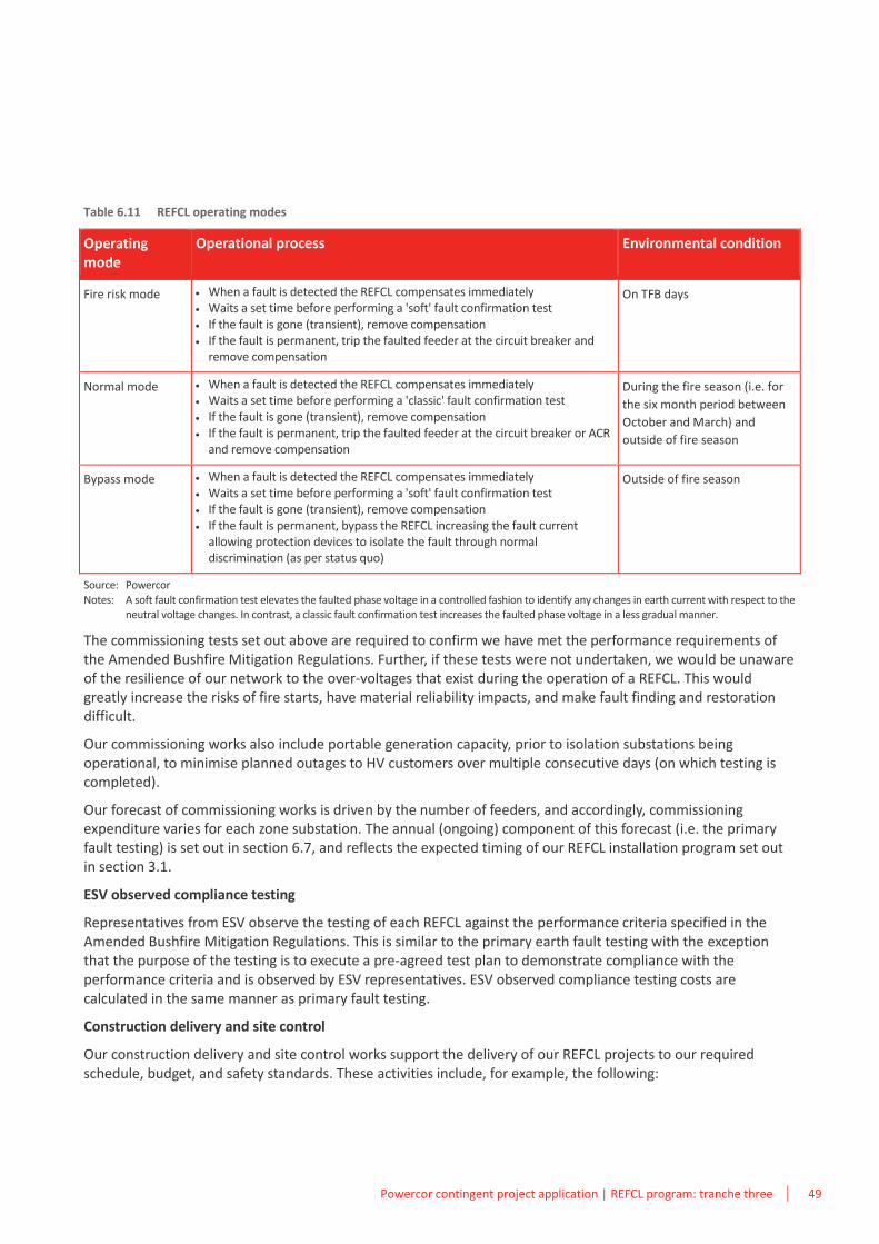
Powercor contingent project application | REFCL program: tranche three 49
Table 6.11 REFCL operating modes
Operating mode
Operational process Environmental condition
Fire risk mode • When a fault is detected the REFCL compensates immediately • Waits a set time before performing a 'soft' fault confirmation test • If the fault is gone (transient), remove compensation • If the fault is permanent, trip the faulted feeder at the circuit breaker and
remove compensation
On TFB days
Normal mode • When a fault is detected the REFCL compensates immediately • Waits a set time before performing a 'classic' fault confirmation test • If the fault is gone (transient), remove compensation • If the fault is permanent, trip the faulted feeder at the circuit breaker or ACR
and remove compensation
During the fire season (i.e. for
the six month period between
October and March) and
outside of fire season
Bypass mode • When a fault is detected the REFCL compensates immediately • Waits a set time before performing a 'soft' fault confirmation test • If the fault is gone (transient), remove compensation • If the fault is permanent, bypass the REFCL increasing the fault current
allowing protection devices to isolate the fault through normal discrimination (as per status quo)
Outside of fire season
Source: Powercor
Notes: A soft fault confirmation test elevates the faulted phase voltage in a controlled fashion to identify any changes in earth current with respect to the neutral voltage changes. In contrast, a classic fault confirmation test increases the faulted phase voltage in a less gradual manner.
The commissioning tests set out above are required to confirm we have met the performance requirements of the Amended Bushfire Mitigation Regulations. Further, if these tests were not undertaken, we would be unaware of the resilience of our network to the over-voltages that exist during the operation of a REFCL. This would greatly increase the risks of fire starts, have material reliability impacts, and make fault finding and restoration difficult.
Our commissioning works also include portable generation capacity, prior to isolation substations being operational, to minimise planned outages to HV customers over multiple consecutive days (on which testing is completed).
Our forecast of commissioning works is driven by the number of feeders, and accordingly, commissioning expenditure varies for each zone substation. The annual (ongoing) component of this forecast (i.e. the primary fault testing) is set out in section 6.7, and reflects the expected timing of our REFCL installation program set out in section 3.1.
ESV observed compliance testing
Representatives from ESV observe the testing of each REFCL against the performance criteria specified in the Amended Bushfire Mitigation Regulations. This is similar to the primary earth fault testing with the exception that the purpose of the testing is to execute a pre-agreed test plan to demonstrate compliance with the performance criteria and is observed by ESV representatives. ESV observed compliance testing costs are calculated in the same manner as primary fault testing.
Construction delivery and site control
Our construction delivery and site control works support the delivery of our REFCL projects to our required schedule, budget, and safety standards. These activities include, for example, the following:
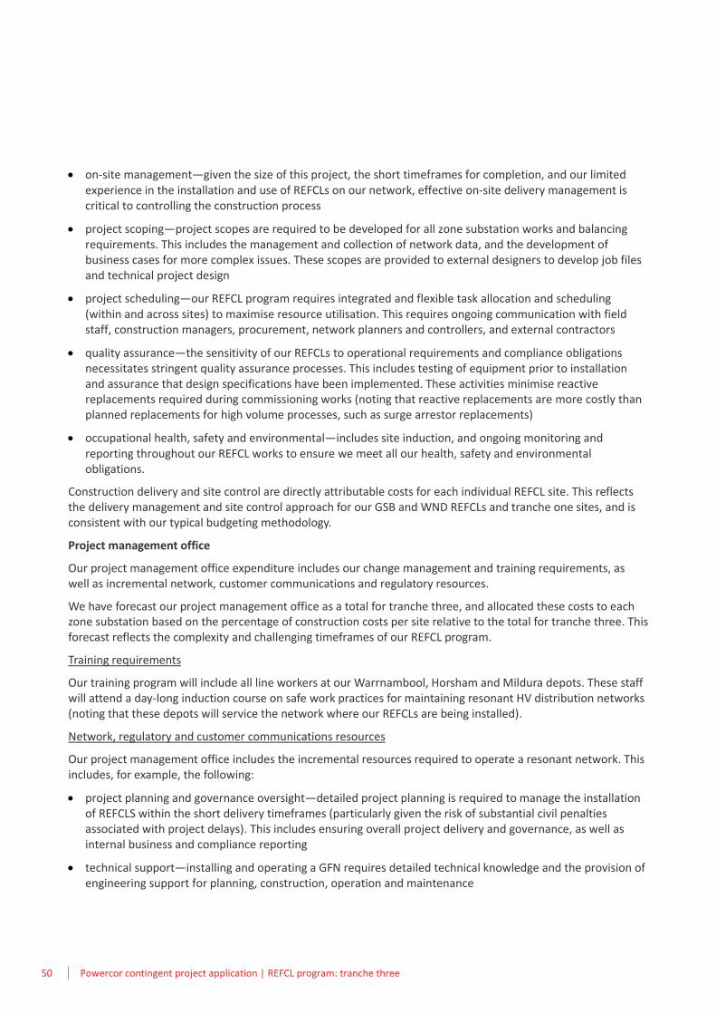
50 Powercor contingent project application | REFCL program: tranche three
• on-site management—given the size of this project, the short timeframes for completion, and our limited experience in the installation and use of REFCLs on our network, effective on-site delivery management is critical to controlling the construction process
• project scoping—project scopes are required to be developed for all zone substation works and balancing requirements. This includes the management and collection of network data, and the development of business cases for more complex issues. These scopes are provided to external designers to develop job files and technical project design
• project scheduling—our REFCL program requires integrated and flexible task allocation and scheduling (within and across sites) to maximise resource utilisation. This requires ongoing communication with field staff, construction managers, procurement, network planners and controllers, and external contractors
• quality assurance—the sensitivity of our REFCLs to operational requirements and compliance obligations necessitates stringent quality assurance processes. This includes testing of equipment prior to installation and assurance that design specifications have been implemented. These activities minimise reactive replacements required during commissioning works (noting that reactive replacements are more costly than planned replacements for high volume processes, such as surge arrestor replacements)
• occupational health, safety and environmental—includes site induction, and ongoing monitoring and reporting throughout our REFCL works to ensure we meet all our health, safety and environmental obligations.
Construction delivery and site control are directly attributable costs for each individual REFCL site. This reflects the delivery management and site control approach for our GSB and WND REFCLs and tranche one sites, and is consistent with our typical budgeting methodology.
Project management office
Our project management office expenditure includes our change management and training requirements, as well as incremental network, customer communications and regulatory resources.
We have forecast our project management office as a total for tranche three, and allocated these costs to each zone substation based on the percentage of construction costs per site relative to the total for tranche three. This forecast reflects the complexity and challenging timeframes of our REFCL program.
Training requirements
Our training program will include all line workers at our Warrnambool, Horsham and Mildura depots. These staff will attend a day-long induction course on safe work practices for maintaining resonant HV distribution networks (noting that these depots will service the network where our REFCLs are being installed).
Network, regulatory and customer communications resources
Our project management office includes the incremental resources required to operate a resonant network. This includes, for example, the following:
• project planning and governance oversight—detailed project planning is required to manage the installation of REFCLS within the short delivery timeframes (particularly given the risk of substantial civil penalties associated with project delays). This includes ensuring overall project delivery and governance, as well as internal business and compliance reporting
• technical support—installing and operating a GFN requires detailed technical knowledge and the provision of engineering support for planning, construction, operation and maintenance
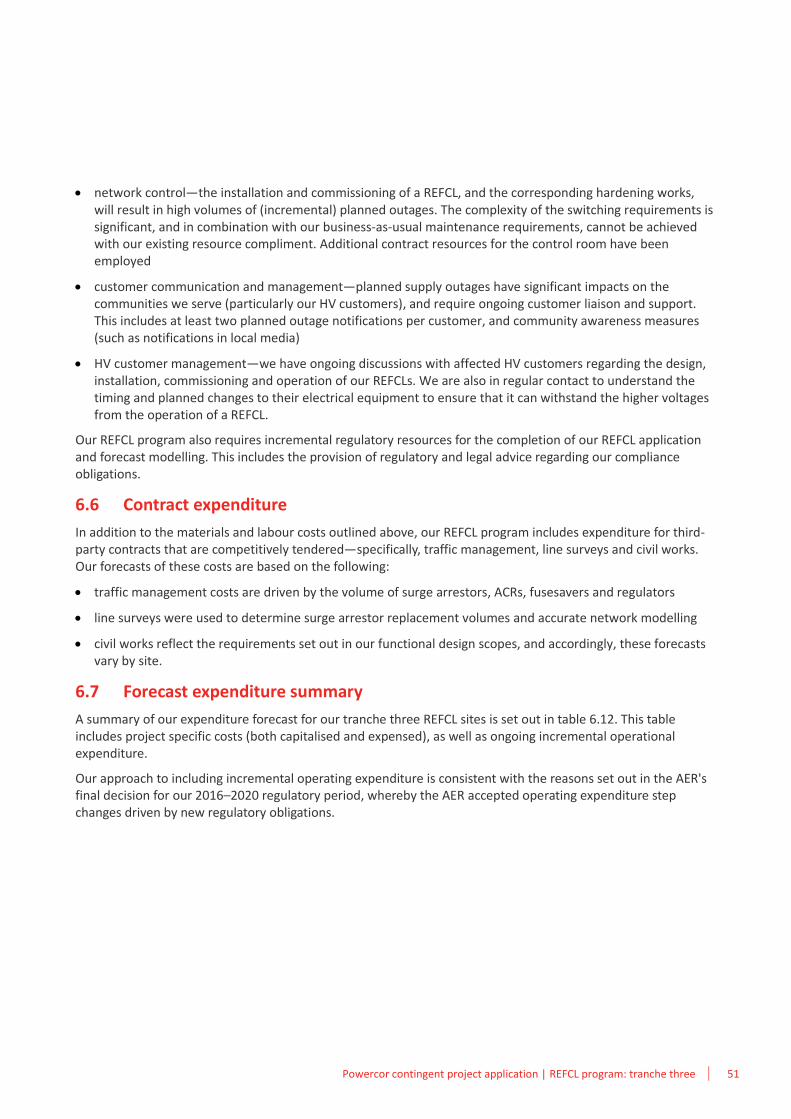
Powercor contingent project application | REFCL program: tranche three 51
• network control—the installation and commissioning of a REFCL, and the corresponding hardening works, will result in high volumes of (incremental) planned outages. The complexity of the switching requirements is significant, and in combination with our business-as-usual maintenance requirements, cannot be achieved with our existing resource compliment. Additional contract resources for the control room have been employed
• customer communication and management—planned supply outages have significant impacts on the communities we serve (particularly our HV customers), and require ongoing customer liaison and support. This includes at least two planned outage notifications per customer, and community awareness measures (such as notifications in local media)
• HV customer management—we have ongoing discussions with affected HV customers regarding the design, installation, commissioning and operation of our REFCLs. We are also in regular contact to understand the timing and planned changes to their electrical equipment to ensure that it can withstand the higher voltages from the operation of a REFCL.
Our REFCL program also requires incremental regulatory resources for the completion of our REFCL application and forecast modelling. This includes the provision of regulatory and legal advice regarding our compliance obligations.
6.6 Contract expenditure
In addition to the materials and labour costs outlined above, our REFCL program includes expenditure for third-party contracts that are competitively tendered—specifically, traffic management, line surveys and civil works. Our forecasts of these costs are based on the following:
• traffic management costs are driven by the volume of surge arrestors, ACRs, fusesavers and regulators
• line surveys were used to determine surge arrestor replacement volumes and accurate network modelling
• civil works reflect the requirements set out in our functional design scopes, and accordingly, these forecasts vary by site.
6.7 Forecast expenditure summary
A summary of our expenditure forecast for our tranche three REFCL sites is set out in table 6.12. This table includes project specific costs (both capitalised and expensed), as well as ongoing incremental operational expenditure.
Our approach to including incremental operating expenditure is consistent with the reasons set out in the AER's final decision for our 2016–2020 regulatory period, whereby the AER accepted operating expenditure step changes driven by new regulatory obligations.
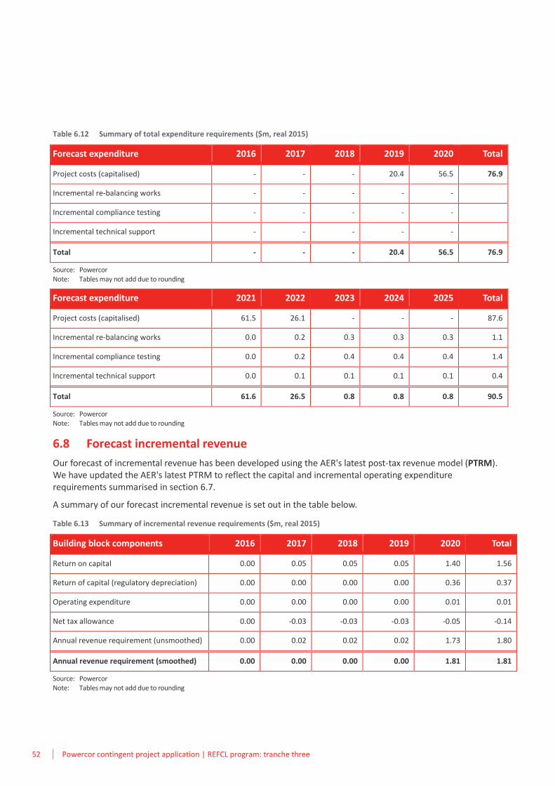
52 Powercor contingent project application | REFCL program: tranche three
Table 6.12 Summary of total expenditure requirements ($m, real 2015)
Forecast expenditure 2016 2017 2018 2019 2020 Total
Project costs (capitalised) - - - 20.4 56.5 76.9
Incremental re-balancing works - - - - -
Incremental compliance testing - - - - -
Incremental technical support - - - - -
Total - - - 20.4 56.5 76.9
Source: Powercor Note: Tables may not add due to rounding
Forecast expenditure 2021 2022 2023 2024 2025 Total
Project costs (capitalised) 61.5 26.1 - - - 87.6
Incremental re-balancing works 0.0 0.2 0.3 0.3 0.3 1.1
Incremental compliance testing 0.0 0.2 0.4 0.4 0.4 1.4
Incremental technical support 0.0 0.1 0.1 0.1 0.1 0.4
Total 61.6 26.5 0.8 0.8 0.8 90.5
Source: Powercor Note: Tables may not add due to rounding
6.8 Forecast incremental revenue
Our forecast of incremental revenue has been developed using the AER's latest post-tax revenue model (PTRM). We have updated the AER's latest PTRM to reflect the capital and incremental operating expenditure requirements summarised in section 6.7.
A summary of our forecast incremental revenue is set out in the table below.
Table 6.13 Summary of incremental revenue requirements ($m, real 2015)
Building block components 2016 2017 2018 2019 2020 Total
Return on capital 0.00 0.05 0.05 0.05 1.40 1.56
Return of capital (regulatory depreciation) 0.00 0.00 0.00 0.00 0.36 0.37
Operating expenditure 0.00 0.00 0.00 0.00 0.01 0.01
Net tax allowance 0.00 -0.03 -0.03 -0.03 -0.05 -0.14
Annual revenue requirement (unsmoothed) 0.00 0.02 0.02 0.02 1.73 1.80
Annual revenue requirement (smoothed) 0.00 0.00 0.00 0.00 1.81 1.81
Source: Powercor Note: Tables may not add due to rounding
AAttachment list

54 Powercor contingent project application | REFCL program: tranche three
This page is intentionally blank.
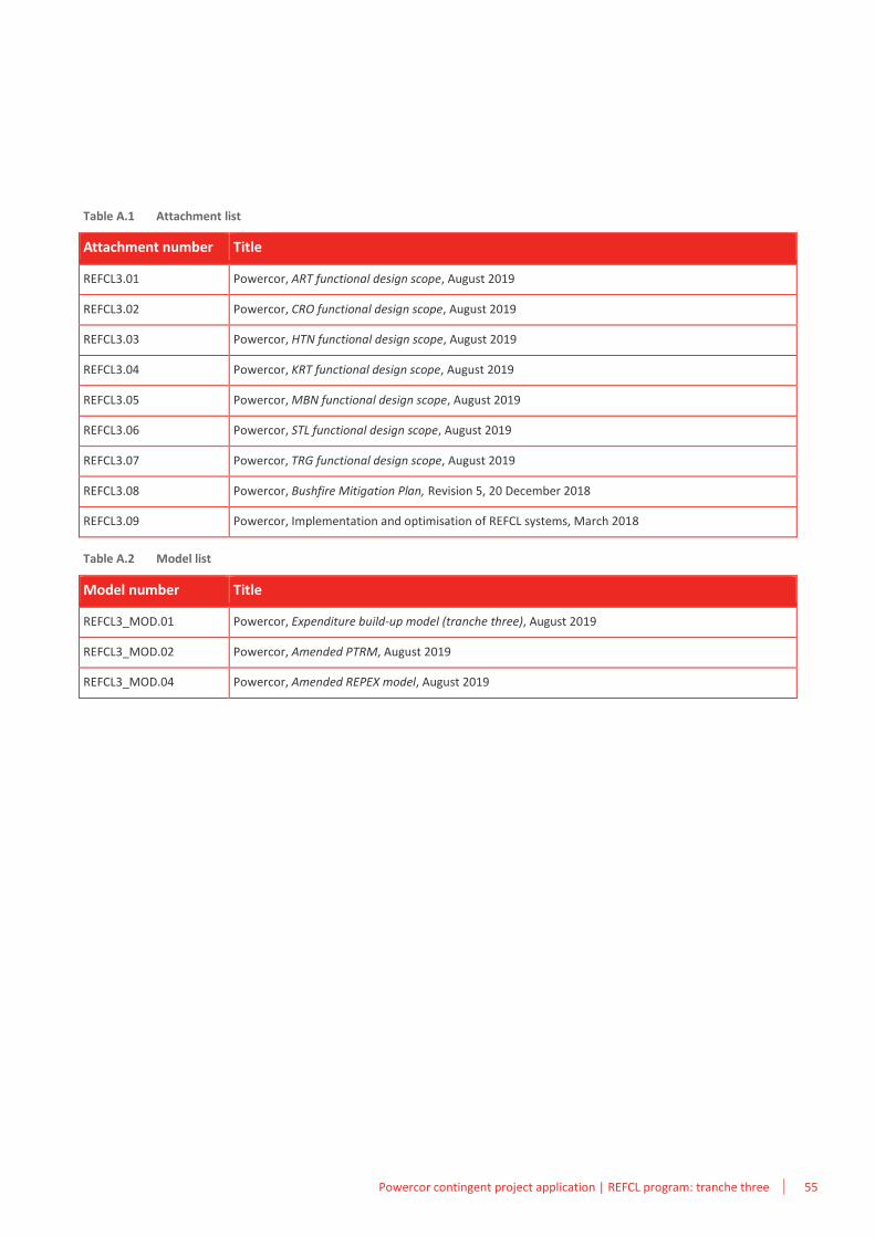
Powercor contingent project application | REFCL program: tranche three 55
Table A.1 Attachment list
Attachment number Title
REFCL3.01 Powercor, ART functional design scope, August 2019
REFCL3.02 Powercor, CRO functional design scope, August 2019
REFCL3.03 Powercor, HTN functional design scope, August 2019
REFCL3.04 Powercor, KRT functional design scope, August 2019
REFCL3.05 Powercor, MBN functional design scope, August 2019
REFCL3.06 Powercor, STL functional design scope, August 2019
REFCL3.07 Powercor, TRG functional design scope, August 2019
REFCL3.08 Powercor, Bushfire Mitigation Plan, Revision 5, 20 December 2018
REFCL3.09 Powercor, Implementation and optimisation of REFCL systems, March 2018
Table A.2 Model list
Model number Title
REFCL3_MOD.01 Powercor, Expenditure build-up model (tranche three), August 2019
REFCL3_MOD.02 Powercor, Amended PTRM, August 2019
REFCL3_MOD.04 Powercor, Amended REPEX model, August 2019

56 Powercor contingent project application | REFCL program: tranche three
This page is intentionally blank.
BCompliance checklist

58 Powercor contingent project application | REFCL program: tranche three
This page is intentionally blank.
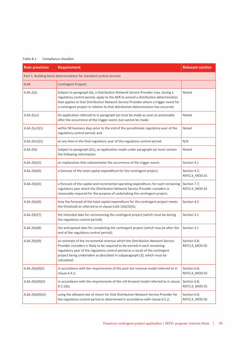
Powercor contingent project application | REFCL program: tranche three 59
Table B.1 Compliance checklist
Rule provision Requirement Relevant section
Part C: Building block determinations for standard control services
6.6A Contingent Projects
6.6A.2(a) Subject to paragraph (b), a Distribution Network Service Provider may, during a
regulatory control period, apply to the AER to amend a distribution determination
that applies to that Distribution Network Service Provider where a trigger event for
a contingent project in relation to that distribution determination has occurred.
Noted
6.6A.2(a1) An application referred to in paragraph (a) must be made as soon as practicable
after the occurrence of the trigger event, but cannot be made:
Noted
6.6A.2(a1)(1) within 90 business days prior to the end of the penultimate regulatory year of the
regulatory control period; and
Noted
6.6A.2(a1)(2) at any time in the final regulatory year of the regulatory control period. N/A
6.6A.2(b) Subject to paragraph (b1), an application made under paragraph (a) must contain
the following information:
Noted
6.6A.2(b)(3) an explanation that substantiates the occurrence of the trigger event; Section 4.1
6.6A.2(b)(4) a forecast of the total capital expenditure for the contingent project; Section 4.2;
REFCL3_MOD.01
6.6A.2(b)(5) a forecast of the capital and incremental operating expenditure, for each remaining
regulatory year which the Distribution Network Service Provider considers is
reasonably required for the purpose of undertaking the contingent project;
Section 7.7;
REFCL3_MOD.01
6.6A.2(b)(6) how the forecast of the total capital expenditure for the contingent project meets
the threshold as referred to in clause 6.6A.1(b)(2)(iii);
Section 4.2
6.6A.2(b)(7) the intended date for commencing the contingent project (which must be during
the regulatory control period);
Section 3.1
6.6A.2(b)(8) the anticipated date for completing the contingent project (which may be after the
end of the regulatory control period);
Section 3.1
6.6A.2(b)(9) an estimate of the incremental revenue which the Distribution Network Service
Provider considers is likely to be required to be earned in each remaining
regulatory year of the regulatory control period as a result of the contingent
project being undertaken as described in subparagraph (3); which must be
calculated:
Section 6.8;
REFCL3_MOD.02
6.6A.2(b)(9)(i) in accordance with the requirements of the post-tax revenue model referred to in
clause 6.4.1;
Section 6.8;
REFCL3_MOD.02
6.6A.2(b)(9)(ii) in accordance with the requirements of the roll forward model referred to in clause
6.5.1(b);
Section 6.8;
REFCL3_MOD.02
6.6A.2(b)(9)(iii) using the allowed rate of return for that Distribution Network Service Provider for
the regulatory control period as determined in accordance with clause 6.5.2;
Section 6.8;
REFCL3_MOD.02
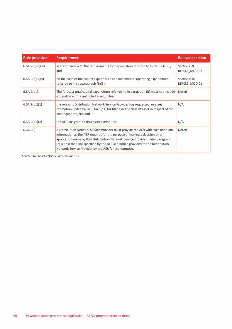
60 Powercor contingent project application | REFCL program: tranche three
Rule provision Requirement Relevant section
6.6A.2(b)(9)(iv) in accordance with the requirements for depreciation referred to in clause 6.5.5;
and
Section 6.8;
REFCL3_MOD.02
6.6A.2(b)(9)(v) on the basis of the capital expenditure and incremental operating expenditure
referred to in subparagraph (b)(3).
Section 6.8;
REFCL3_MOD.01
6.6A.2(b1) The forecast total capital expenditure referred to in paragraph (b) must not include
expenditure for a restricted asset, unless:
Noted
6.6A.2(b1)(1) the relevant Distribution Network Service Provider has requested an asset
exemption under clause 6.6A.1(a1) for that asset or class of asset in respect of the
contingent project; and
N/A
6.6A.2(b1)(2) the AER has granted that asset exemption. N/A
6.6A.2(i) A Distribution Network Service Provider must provide the AER with such additional
information as the AER requires for the purpose of making a decision on an
application made by that Distribution Network Service Provider under paragraph
(a) within the time specified by the AER in a notice provided to the Distribution
Network Service Provider by the AER for that purpose.
Noted
Source: National Electricity Rules, version 123


![[Draft]thailand's 3rd ict master plan](https://static.fdocuments.in/doc/165x107/55950fc81a28ab0e108b459a/draftthailands-3rd-ict-master-plan.jpg)
