Healthcare Review 1(2), 2020 ISSN 2692-8787 Antibacterial ...

UMV 2301 ASSpeed controller for asynchronous motors
Installation and maintenance
Réf. 2692 - 4.33 / a - 1.98
This manual must be sent
to the end user

1 - UL LISTING INFORMATION
The Drive conforms to UL listing requirements only whenthe following are observed :• The Drive is installed in a type 1 enclosure, or better,as defined by UL50.• UL listed fuses class RK1 600Vac are used in the ACsupply.• Class 160/75°C (140/167°F) copper wire only is used inthe installation.• The ambient temperature does not exceed 40°C(104°F) when the Drive is operating.• The terminal tightening torques specified in the table inTerminal sizes and tightening torques in Chapter 2 in-stalling the Drive are used.
2 - INSTALLING THE DRIVE
• UL listing is valid when the Drive is installed in a type 1 enclosure, or better,as defined by UL50.
2.1 - Planning the installation
UL listing is dependent on the use of the correct typeof UL listed fuse, and applies when the symmetricalshort-circuit current does not exceed 5 kA for modelsizes 8T to 50T, and 10 kA for model size 60T to120T.
2.2 - Terminal sizes and tightening torques
• To avoid a fire hazard and maintain validity of the UL listing, adhere to the specified tightening torques for the power and ground terminals. Refer to the following tables.
Drive
RFI filter
1
Speed controllerfor asynchronous motorsUMV 2301 AS
Ref. 2881 - 4.33 / a - 2.98
ADDENDUMUL MARKING REQUIREMENTS
Model Fuse rating
UMV 2301 AS 8T 16A
UMV 2301 AS 11T 20A
UMV 2301 AS 16T 35A
UMV 2301 AS 22T 40A
UMV 2301 AS 27T 50A
UMV 2301 AS 33T 60A
UMV 2301 AS 40T 70A
UMV 2301 AS 50T 80A
UMV 2301 AS 60T 100A
UMV 2301 AS 75T 125A
UMV 2301 AS 100T 160A
UMV 2301 AS 120T 200A
Warning
Warning
Power Ground
Model terminals terminals
Size Torque Size Torque
type typeUMV 2301 AS8T to 16T
Plug-interminalblock
0.5Nm4.4 lb.in
M4(Torx/slot-headscrew)
3N.m 26.6 lb.in
UMV 2301 AS22T to 50T
M8stud
25 N.m221 lb.in
M8stud
25 N.m221 lb.in
UMV 2301 AS60T to 120T
M10stud
25 N.m221 lb.in
M10stud
25 N.m221 lb.in
Torque tolerance ± 10 %
Size Part No. Torque
A FLT 30100.7 N.m6 lb.in
B FLT 30271.6 N.m14 lb.in
C FLT 105712.6 N.m111 lb.in
D FLT 107112.6 N.m111 lb.in
E FLT 111125 N.m221 lb.in
F FLT 117125 N.m221 lb.in
Torque tolerance ± 10 %

2.3 - Using the gland plate and cable glands
• When the gland plate(s) are not fitted, objects less than 60 mm (2 1/2 In) widecan pass through the cable entry opening and possibly make contact withlive parts inside the Drive.
Fit the gland plate and cable glands as required.Before fitting cable glands, push out sufficient blankingcaps from the grand plate.
Note that the IP rating of the Drive is reduced if any ho-les in the gland plate are left open. The rating is affectedas follows :
2
Speed controllerfor asynchronous motorsUMV 2301 AS
Warning
Gland plate not fitted IP00Gland plate fittedUnused holes uncovered IP10
Gland plate and glands fittedBlanking caps covering unused holes IP40
Gland plate hole diameterModel size Control signal
wiring Power cables
UMV 2301 AS8T to 16T
20 mm3/4 in
20mm3/4 in
UMV 2301 AS22T to 50T
20 mm3/4 in
28mm11/4 in
UMV 2301 AS60T to 120T
20 mm3/4 in
28mm11/4 in

2
Speed controller forasynchronous motorsUMV 2301 AS
NOTE
LEROY-SOMER reserves the right to modify the specifications of its products at any time in order to incorporate thelatest technological developments. The information enclosed in the present document may therefore change without notice.
LEROY-SOMER gives no contractrual guarantee whatsoever concerning the information published in this document andcannot be liable for any error it may contain nor for any damage arising from its use.
CAUTION
For the own safety of the user, this speed controller must be connected to an approved earth (terminal B ).
If an accidental start of the installation represents a risk for personnel or the machines to be driven, it is imperative that thepower supply of the drive is fitted with an isolating switch and a circuit-breaking device (power contactor) controllable through anexternal safety system (emergency stop, fault detector).
The speed controller is fitted with safety devices which can stop the controller in the event of faults and thus stop the motor. Themotor itself can be jammed for mechanical reasons. Finally, voltage fluctuations, and particularly power cuts, can also cause themotor to switch off.The cure of the causes of the shutdown can lead to restarting, which may be dangerous for certain machines or installations.In such cases, it is essential that the user makes appropriate arrangements against restarting after unscheduled stops of themotor.The speed controller is designed to be able to power a motor and the driven machine above its rated speed.If the motor or the driven machine is not mechanically designed to operate at such speeds, the user risks serious injuryfrom the resulting mechanical damage. Before programming a high speed, it is essential that the user ensures that the system can withstand it.
The speed controller is a component designed for integration within an installation or an electrical machine : it is therefore of theresponsibility of the user to make sure the system complies with current standards.
LEROY-SOMER declines all responsibility whatsoever should the above recommendations not being complied with.
........................................
Manual corresponding to software version 1.1.1
For more recent software versions, refer to enclosed appendix or ask LEROY-SOMER

Throughout the manual, this symbol warns against consequences which may arise from
inappropriate use of the speed controller, sinceelectrical risks may lead to material or physicaldamage as well as constitute a fire hazard.
1 - GeneralAccording to their degree of protection, speed controllerscan during operation comprise bare live parts,sometimes moving or rotating, as well as hot surfaces.Unjustified removal of protections, incorrect use, faultyinstallation or inappropriate operation could represent aserious risk to personnel and machinery. Refer to themanual for additional information.Any work related to transportation, installation,commissioning and maintenance must be carried out byexperienced and qualified personnel (see CEI 364 orCENELEC HD 384, or DIN VDE 0100 and nationalspecifications for installation and accident prevention).According to these basic safety instructions, qualifiedpersonnel means persons competent to install, mount,commission and operate the concerned product andpossessing the relevant qualifications.
2 - UseSpeed controllers are components designed forintegration within an installation or an electrical machine.When integrated in a machine, commissioning isforbidden as long as conformity with Directive89/392/CEE (Machinery Directive) has not beenchecked. It is also necessary to comply with standard EN60204, which especially stipulates that electricalactuators (which include speed controllers) cannot beregarded as circuit-breaking devices and by no meansas isolating switches. Commissioning can take place only if the requirementsof the Electromagnetic Compatibility Directive(89/336/CEE, modified by 92/31/CEE) are fulfilled.Speed controllers fulfil the requirements of the LowVoltage Directive 73/23/CEE, modified by 93/68/CEE.The harmonized standards of the DIN VDE 0160 seriesin connection with standard VDE 0660, part 500 and EN60146/VDE 0558 are also applicable.Technical specifications and instructions concerningconnection conditions specified on the rating plate and inthe supplied documentation must absolutely berespected without fail.
3 - Transportation, storageAll instructions concerning transportation, storage andcorrect handling must be respected.Climatic conditions specified in the technical manualmust be respected.
4 - InstallationInstallation and cooling of equipment must comply withthe specifications stated in the manual supplied wit theproduct.Speed controllers must be protected against excessivestress. More particularly, avoid any damage to partsand/or modification of insulation distances betweencomponents during transportation and handling. Avoidtouching electronic components and contact parts.Speed controllers include parts which are sensitive toelectrostatic stress and can easily be damaged ifhandled incorrectly. Electrical components must not beexposed to mechanical damage or destruction (possiblerisks to health !).
5 - Electrical connectionWhen work is carried out on the powered-up speedcontroller, national specifications for accident preventionmust be respected.Electrical installation must conform with the appropriatespecifications (for instance wire section, protection withcircuit-breaking fuse, connection of protectiveconductor). Refer to the documentation for more detailedinformation.Instructions for an installation complying withelectromagnetic compatibility requirements (such asscreening, earthing, presence of filters and correctmounting of cables and conductors) are outlined in thedocumentation supplied with the speed controller. Theseinstructions must always be respected even if the speedcontroller has the CE mark. The manufacturer of theinstallation or of the machine is responsible for theconformity with the limits given in the EMC legislation.
6 - OperationInstallations incorporating speed controllers must befitted with additional protection and monitoringequipments specified in the current relevant safetyregulations, such as law on electrical equipment,specifications for accident prevention, etc…Modifications to speed controllers using control softwareare allowed.After the speed controller has been powered down,active parts of the equipment and live power connectionsmust not be touched immediately as the capacitors maystill be charged. In view of this, refer to the warningsmarked on the speed controllers.During operation, all doors and protections must remainclosed.
7 - Service and maintenanceRefer to the manufacturer's documentation.
This document must be passed on to the end user.
3
Speed controller for asynchronous motorsUMV 2301 AS
SAFETY AND OPERATING INSTRUCTIONS CONCERNING SPEED CONTROLLERS(According to low voltage directive 73/23/CEE modified by 93/68/CEE)
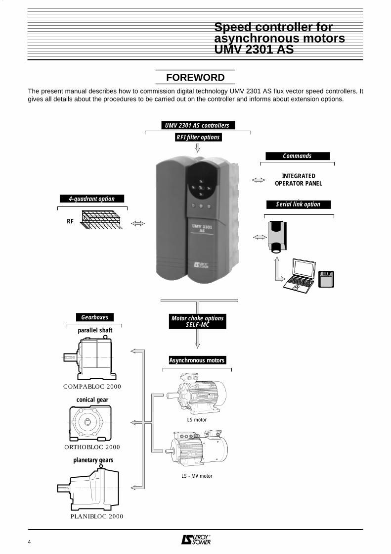
FOREWORDThe present manual describes how to commission digital technology UMV 2301 AS flux vector speed controllers. Itgives all details about the procedures to be carried out on the controller and informs about extension options.
4
parallel shaft
conical gear
COMPABLOC 2000
ORTHOBLOC 2000
Asynchronous motors
Gearboxes
UMV 2301 AS controllers
RFI filter options
Commands
Serial link option
planetary gears
PLANIBLOC 2000
RF
INTEGRATEDOPERATOR PANEL
LS motor
4-quadrant option
LS - MV motor
Motor choke optionsSELF-MC
Speed controller for asynchronous motorsUMV 2301 AS

5
CONTENTS
Pages1 - GENERAL INFORMATION
1.1 - General operating principle ............................................................................................... 6 - 71.2 - Product designation ........................................................................................................... 81.3 - Specifications ..................................................................................................................... 8 to 101.4 - Environmental specifications ............................................................................................. 111.5 - Weight and dimensions ..................................................................................................... 11
2 - MECHANICAL INSTALLATION 2.1 - Checks on receipt ............................................................................................................. 122.2 - Installation precautions ...................................................................................................... 122.3 - Installing the controller ....................................................................................................... 12 to 15
3 - CONNECTIONS3.1 - Connection of asynchronous motor ................................................................................. 163.2 - Connection of controller ... ............................................................................................... 17 to 203.3 - Description of cables and protections ............................................................................ 213.4 - Particular connections ........................................................................................................ 223.5 - Electrical and electromagnetic phenomena ...................................................................... 23 to 273.6 - Block diagrams ................................................................................................................. 28 to 34
4 - COMMISSIONING4.1 - Procedure for using the operator console .......................................................................... 35 to 374.2 - Starting-up the controller .................................................................................................... 38 - 394.3 - Menu 0 .............................................................................................................................. 40 to 504.4 - Fault processing ................................................................................................................. 51 - 524.5 - Other menus...................................................................................................................... 53 to 97
5 - FAULTS - DIAGNOSIS5.1 - Display of drive trip codes ....................................................................................................98 - 995.2 - Display of controller status ................................................................................................. 995.3 - Display of controller alarms................................................................................................ 995.4 - Logic output signals ............................................................................................................ 99
6 - MAINTENANCE6.1 - Introduction and advice ..................................................................................................... 1006.2 - Service ............................................................................................................................... 1006.3 - Voltage, current and power measurements ....................................................................... 1006.4 - Spare parts list .................................................................................................................. 1006.5 - Replacement of products ................................................................................................... 100
7 - OPERATING EXTENSIONS7.1 - Serial link option ................................................................................................................. 1017.2 - RF braking resistors ........................................................................................................... 1017.3 - RFI filters ............................................................................................................................... 102 - 1037.4 - Three-phase motor chokes for attenuation of leakage current : Self-MC ...............................103
8 - SUMMARY OF SETTINGS ............................................................................................................105 - 106
Speed controller for asynchronous motorsUMV 2301 AS

1 - GENERAL INFORMATION
1.1 - Operating principle1.1.1 - GeneralThe UMV 2301 AS is an AC power controller forasynchronous motors.The UMV 2301 AS controller is fitted with an inverterbridge with IGBT transistors.This advanced technology considerably reduces noiseand temperature rise for variable speed inductionmotors.Performance of the UMV 2301 AS controller areperfectly suitable for use in all 4 quadrants of the torque -speed diagram.During periods of operation in generator mode, theenergy restored by the motor is dissipated in resistors.
1.1.2 - Block diagram
6
Speed controller forasynchronous motorsUMV 2301 AS
M3
Calcul.
P.I.D.
3 referencesare
determined
Power
bridge
Mains
PWM
Speedimage
w/ofeedb.
PID
PID
Speedref.
I magnet.ref.
I cos ϕ
I sin ϕ
Currentcalculation
Torqueref.
Speedloop
Selection
Torqueloop
Reactiveloop
DCBus
Motorparameters

1.1.3 - Organization chart of menus
7
Speed controller forasynchronous motorsUMV 2301 AS
1 5 0 0 0r d y
M
Menu 0 (page 40)
User menu• Direct access to power-up• Storage of most commonly used parameters - Minimum and maximum frequency - Acceleration and deceleration ramps - Current limits - Frequency skips - Preset frequencies - Choice of signal on analogue input - Motor parameters - Serial link configuration
Menu 6 (page 59)
Configuration of hourmeterfunction
• Command processing• Start processing• Microcut processing• Stop processing• Hourmeter• Energy meter• Running time alarms
Menu 1 (page 53)
Select speed referencesfrequency clamps
• Select analogue references, preset frequencies, keypad references…• Jogging• Frequency clamp• Frequency skips
Menu 7 (page 67)
Re-configuration of analogueinputs / outputs
• Type of signal• Offset• Scaling• Sign inversion• Destination or source
Menu 9 (page 79)
Logic functions
• AND/OR functions• Timers• Faster/Slower function• Binary/decimal converterl
Menu 8 (page 73)
Re-configuration of logicinputs / outputs
• Select input or output• Inversion• Destination or source
Menu 12 (page 91)
Programmable thresholds
• Analogue comparators• Hysteresis• Logic inversions
Menu 14 (page 95)
PID regulation
• PID ramp reference• Enabling conditions• PID settings• Clamps• Scaling
OptionalSerial Link
COM 1 UMV
12345678910112122232425262728293031
Control
Optionalresistor
U
V
WM
L1
L2
L3
00.00 = 149
Menu 10 (page 85)
Status of controller and diagnosis• Fault processing• Braking resistor

1.3 - Specifications1.3.1 - Main electrical data
1.3.2 - Electrical output data
- : No deratingX : Frequency not available
8
Speed controller forasynchronous motorsUMV 2301 AS
UMV 2301 AS 8T
ENTRÉE / INPUT3 Ph 380/480V
SORTIE / OUTPUT3 Ph 0-380/480 V 4kW
12 A 13.7 ADate : 11/08/97Serial N° 327310002
14.4A/60S
SW 01.01.01
Il est indipensable de lire la noticeavant de raccorder cet appareil
It is essential to read the instructionsbefore connecting the inverter
Après mise hors tension,attendre 10 minutes pour
toute intervention dans l'appareil
After switching off the inverter,wait 10 minutes before performing
maintenance or inspection
CT Ref : UNI 2401 VTC
Inputdata
Outputdata
Serial nrSoftware version
Power supply 3-phase supply 380V to 480V ± 10 %
Input frequency 48Hz to 62Hz
Phase unbalance of input ≤ 3 %
Output voltage From 0V to input voltage
Maximum number of power-ups per hour 20
Data for switching frequency = 3kHz Permanent rated currentUMV Effective Permanent Overload for switching frequency > 3 kHz
2301 ASrating
CTref.
motorpower
at 400V
ratedcurrent
currentduring 60s 4,5 kHz 6 kHz 9 kHz 12 kHz
(kW) (A) (A) (A) (A) (A) (A)
8T UNI 2401 VTC 5,5 12 14,4 - - - -
11T UNI 2402 VTC 7,5 16 19,2 - - - 13
16T UNI 2403 VTC 11 25 30 - 22 16 13
22T UNI 3401 VTC 15 34 40,8 - - X X
27T UNI 3402 VTC 18,5 40 48 - - X X
33T UNI 3403 VTC 22 46 55,2 - - X X
40T UNI 3404 VTC 30 60 72 - 50 X X
50T UNI 3405 VTC 37 74 88,8 X X X X
60T UNI 4401 VTC 45 96 115 X X X X
75T UNI 4402 VTC 55 124 148 X X X X
100T UNI 4403 VTC 75 156 187 X X X X
120T UNI 4404 VTC 90 180 216 X X X X
1.2 - Product designationUMV 2301 AS : open loop speed controller operating with flux vector control mode or voltage / frequency control (V to F mode).
8 = Rating in kVA at 400V, T = 3-phase supply.This designation appears on the nameplates located on the upper side of the controller.

9
Speed controller forasynchronous motorsUMV 2301 AS
1.3.3 - Specifications and main functions of basic menu 0
Regulation mode • Vector control, open loop• Voltage / frequency control (U/F)
Regulation • Speed reference
Constant torqueConstant power
Adjusted by basic frequency
DESCRIPTIONUMV 2301 AS
8T to 16TUMV 2301 AS
22T to 50TUMV 2301 AS60T to 120T
Overload capacity • 120 % of controller rated current during 60s
Braking • Hypersynchronous. Controller alone or with RF options• Through DC injection
Control logic • Negative high level > + 15V• Positive low level < + 5V
Speed references
• Analogue :- differential voltage ± 10V (input impedance : 100 KΩ)- voltage 0/± 10V in common mode (input impedance : 100 KΩ)- current 0-20mA, 4-20mA or 20-0mA, 20-4mA
• Digital :- from keypad- by pulses whilst running
Forward / reverse command• Through inversion of reference polarity• Through logic inputs• From operator console
Controller / motor self-adaptation
Measurement of motor data (cos ϕ, magnetizing current and statoric resistances).
CONTROL
Switching frequency 3 - 4,5 - 6 - 9 and 12 kHz 3 - 4,5 - 6 kHz 3 kHz
FUNCTION
Acceleration / deceleration ramps
Separate settings from 0 to 3200s. Linear or " S " curve.Radius of " S " ramp can be adjusted.
Minimum/maximum speedlimitation
Speed variation between 2 stops.
Stop mode • Coast stop : through logic input (terminal 30) instantaneous cut-out of motor power supply.• Ramp stop (following different modes).• DC injection braking stop.
Select dynamic V to F mode Automatic adaptation of V/F curve to motor load in V to F mode.Catch spinning motor Possibility to start the controller whilst the motor is running.

10
Speed controller forasynchronous motorsUMV 2301 AS
TRIPSUMV 2301 AS
8T to 16TUMV 2301 AS
22T to 50TUMV 2301 AS60T to 120T
INDICATIONS
Display On operator console:- Output frequency (Hz) or motor speed (min-1),- Output current (A).
Relay Relay 250 VAC - 5A (resisting charge)
Logic output Commutator open : external source from 0 to +24V 100 mAActive : - open loop : at speed,
- closed loop : zero speed.Analogue output - 0 to ±10V 10mA
OPTIONS
Communication option Integrated in the UMV 2301 AS- serial link RS 485 and RS 232, protocole ANSI x 3.28 : COM 1 UMV
Resistor brakingRF
RF 320Tto
RF 5500T
RF 320Tto
RF 18500T
RF 320Tto
RF 55000T
Central unit failure Fault internal to controller and options External trip Fault forced through terminal block (terminal 30).
Overload (I x t) Electronic thermal relay for motor and braking resistor.
Overheating • Controller : radiator and electronic cards.• Motor : with PTC probe : - trip for PTC > 3 kΩ,
- reset for PTC ≤ 1,65 kΩ,- PTC detection in short-circuit, (≤ 4 Ω in TH SC mode)
with PTO probe.Overcurrent 200 % of rated current.
Short-circuit : phase-phase/phase-earth.Phase lossPhase imbalance
Mains power cut.
Under- and overvoltage,DC bus
DC bus voltage out of its normal operating range.
Internal power supply Monitoring of controller internal power supplies.
Filters for attenuation ofradio interferences
FLT - 3027 FLT - 1051 - 1071 - 1111 FLT - 1111 - 1171
Motor chokes for attenuation of leakage current
Self MC 5,5T, 11T and 27T Self MC 27T and 50T Self MC 75T and 120T

1.4.2 - Loss tables (W)
1.5 - Weight and dimensions
11
Speed controller forasynchronous motorsUMV 2301 AS
1.4.3 - Table over forced ventilation flow rate (m3 h)
Switching UMV 2301 ASfrequency 8T 11T 16T 22T 27T 33T 40T 50T 60T 70T 100T 120T
3 kHz 190 250 390 550 640 700 920 1120 1430 1860 2320 26004,5 kHz x x x x x x6 kHz 410 770 800 860 x x x x x x9 kHz 320 x x x x x x x x x x12 kHz 300 x x x x x x x x x x x
Forced UMV 2301 ASventilation 8T 11T 16T 22T 27T 33T 40T 50T 60T 70T 100T 120TFlow (m3 h) 85 320 640
Rating Dimensions (mm) Weight
UMV 2301 AS H L P (kg)
8T to 16T 335 190 200 8
22T to 50T 335 375 260 22
60T to 120T 700 500 260 70
UMV 2301 AS
1 5 0 0 01 5 0 0 0r d y
M
L P
H
Specifications LevelChest protection IP40Storage temperature - 40 °C to + 50 °C, maximum 12 months.Operating temperature - 5 °C to + 40 °C.Altitude • ≤ 1000 m without derating.
• Derating : 1 % of IN per 100 m above 1000m up to 4000m maximum.Humidity Without condensation.Vibration According to CEI 68-2-34Shocks According to CEI 68-2-27Immunity According to : - CEI 801-2 Level 3
- CEI 801-3 Level 3 - CEI 801-4 Level 3 (power), Level 4 (control)
Emissions conducted According to : - EN 50081-1 (VDE 875 N) with : switching frequency 3 kHz and filter for UMV 4301 1.5T to 16T - EN 50081-2 (VDE 875 G) UMV 4301 from 1.5T to 120T
radiated According to EN 50081-2
1.4 - Environmental specifications
• Protection index of UMV 2301 AS controllers is IP 40.• They are designed for installation in a cubicle or a chest in order to protect them against dust and
condensation. Access of non-qualified personnel should be prohibited.
1.4.1 - General

2 - MECHANICAL INSTALLATION
• The owner or user is responsible for making sure that installation, operation and service of
the controller and its options comply with legislationrelating to the safety of machinery and personnel,and with current regulations of the concernedcountry.
• UMV 2301 AS controllers must be installedin an environment free from conducting dust, fumes,corrosive fluids and gases and from condensation(for instance class 2 according to UL 840 and CEI664.1). The controller must not be installed in ahazardous area unless it is enclosed in a speciallyadapted cubicle. In this case the installation must becertified.
• Within atmospheres subject to condensa-tion, it is necessary to install a heating system whichfunctions when the controller is not in use and isdisconnected when the controller is operating.Ideally this heating system should be controlled au-tomatically.
• The housing of the UMV 2301 AS controlleris not fireproof : therefore it might be necessary touse a fireproof cubicle.
• The UMV 2301 AS rating more than 22Tweigh more than 22 kg. They should be handledusing adapted means.
2.1 - Checks on receiptBefore installing the controller, make sure that :- the controller has not been damaged during transport,- all mounting accessories are included,- the nameplate is corresponding to the power supplyand motor specifications.
2.2 - Installation precautions
The controller should be mounted upright with aclearance of 100 mm over and under.Do not mount the UMV 4301 controller over a heatsource or another controller. There is a risk fortripping when the radiator temperature reaches 90°C.Never obstruct the ventilation louvres.The UMV 2301 AS 60T to 120T controllers aresupplied with 2 M10 tapped holes for fittingshackles.
2.3 - Installation of the controller
2.3.1 - GeneralThere are 2 differents ways to install the controller :heat sink inside or outside of cubicle. With the latterconfiguration it is not necessary to dissipate thecontroller losses.
- UMV 2301 AS from 8T to 16T
12
Speed controllers forasynchronous motorsUMV 2301 AS
SCREW
SCREW
UMV 2301AS
1 5 0 0 0r d y
M
L2L2
Mountingsupport
H1
H
H2
LL1
P

- UMV 2301 AS from 22T to 50T
13
Speed controllers forasynchronous motorsUMV 2301 AS
- UMV 2301 AS from 60T to 120T
SCREW
SCREW
UMV 2301AS
1 5 0 0 01 5 0 0 0r d yr d y
M
P L2L2L1
MountingsupportH
H1
H2
L
SCREW
UMV 2301AS
1 5 0 0 01 5 0 0 0r d yr d y
M
P
L2 L2
Mountingsupport
H1
H2
L3 L3L
SCREW
L4 L4
H
Dimensions
UMV 2301 AS Dimensions (mm)
rating H H1 H2 L L1 L2 L3 L4 P VIS
8T to 16T 335 368 345 190 95 16,5 - - 200 M6
22T to 50T 335 368 345 375 187,5 16,5 - - 260 M6
60T to 120T 700 743 717,5 500 250 - 65 143,5 260 M6
2.3.2 - Mounting with heat sink inside the cubicleThe UMV 2301 AS 8T to 16T controllers must absolutely be mounted on a massive base plate in order to direct thecooling air flow efficiently : otherwise, 20 % derating is necessary.The UMV 2301 AS controllers 22T to 120T can also be mounted on a grille, a frame or a DIN rail support.- Insert the mounting lugs into the grooves on top and under the heat sink,- Fasten the lugs onto the base plate, the DIN rail support or the grille with M6 screws.

14
4 - Set on the frame the gasket suplied with thecontroller.5 - Insert the controller in the cut-out of the rear panel.6 - Fasten the controller through the upper mountingsand the lower holes.
WARNING : Make sure that the air flow beyond the cubicle issufficient.
2.3.3 - Mounting with heat sink outside of cubicle1 - Cut out and drill the rear panel of the cubicle.2 - Insert a mounting lug into the groove on top ofcontroller.3 - For the UMV 2301 AS controllers rating 22T to 50Tand 60T to 120T, remove the lower terminal block coverin order to get access to the mounting holes.
- Cut-out drawingsUMV 2301 AS from 8T to 16T
UMV 2301 AS from 22T to 50T
Speed controllers forasynchronous motorsUMV 2301 AS
UMV 2301AS
1 5 0 0 01 5 0 0 0r d yr d y
MMountingsupport
H
Cut-out
LH2
H1
P P1
L1 L1
1 5 0 0 01 5 0 0 0r d yr d y
M
P
H H1
L1 L1
L2H4 L2H3
L
Cut-out
Mountingsupport
P1L3
UMV 2301AS

15
- Cut-out drawings (continued)UMV 2301 AS from 60T to 120T
Dimensions (mm)
Add thickness of gasket. Deduct thickness of gasket.
Speed controllers forasynchronous motorsUMV 2301 AS
UMV 2301 AS Dimensions (mm)
rating H H1 H2 H3 H4 H5 L L1 L3 L2 P* P1** VIS
8T to 16T 345 295 12,5 - - - 182 - - - 120 80 M6
22T to 50T 345 287 - 16 7 - 358 16,5 131,5 69 120 140 M6
60T to 120T 717,5 650 - 17 7,5 3,5 482 65 192 130 120 140 M6
1 5 0 0 01 5 0 0 0r d yr d y
M
P P1
H
B
L2L3
H4 L2
L1 L1H5
H3
L
Cut-out
Mountingsupport
UMV 2301AS
H1

3 - CONNECTIONS
• All connection works must be carried out according to the current legislation of the
concerned country. This includes earthing orgrounding in order to make sure that no directlyaccessible part of the controller can remain at mainspotential or any other voltage that may behazardous.
• The voltages existing on the wires orconnections to the mains, the motor, the brakingresistor or the filter, may cause fatal electric shocks.Avoid contact in any case.
• The controller must be supplied through acircuit-breaking device in order to disconnect itsafely.
• The controller power supply must beprotected against overloads and short-circuits.
• The stop function of the controller does notprotect against the high voltages existing on theterminal blocks.
• The controller contains capacitors whichremain charged at a fatal voltage even after thepower supply has been cut off.
• After the power supply has been cut off, waitfor 10mn before removing protective cover.
• Make sure that voltage of DC bus is lowerthan 40V before any work is carried out.
• Check that voltage and current of controller,motor and mains are compatible.
3.1 - Connection of induction motor3.1.1 - Terminal blockThe LS MV motors are mainly dual-voltage motors,230/400V. As standard, star-connection should thus beused.
Nevertheless, check the nameplate before connectingthe motor.
3.1.2 - Auxiliary terminal blocks3.1.2.1 - Optionel forced ventilationLS MV motors can be fitted with an optional forcedventilation as follows :• Motor LS MV with frame size ≤ 132, single-phasepower supply as standard :
• Motor LS MV with frame size ≥ 160
Refer to LS MV motor catalogue for further information.
16
W2 U2 V2
U1 V1 W1
To controller
U Z
W V
U = 230V ~ on U and W
U = 400V ~ on V and W
Speed controllers forasynchronous motorsUMV 2301 AS
U1
L1 L2 L3
W2 U2 V1 W2 U2 V2
U1 V1 W1V1 W1
L1 L2 L3
Forced ventilation power supply
U : 230V U : 400V

3.2 - Connection of controller3.2.1 - Power terminal block3.2.1.1 - Access to power terminal blocks• UMV 2301 AS 8T to 16T
Remove the plastic cover on control side by slightlyparting both lower edges.
• UMV 2301 AS 22T to 120T
Remove the plastic cover on control side by slightlyparting both lower edges.
3.2.1.2 - Wiring of power terminal block• UMV 2301 AS 8T to 16T
Tightening torque of power terminal blocks : 0,5 Nm.
• UMV 2301 AS 22T to 120T
Tightening torque of power terminal blocks : 25 Nm.
Never connect the resistance directly betweenterminals + and -.
17
Speed controllers forasynchronous motorsUMV 2301 AS
L1 L2 L3 U V + • -W
1 5 0 0 01 5 0 0 0r d yr d y
M
UMV 2301AS
1 5 0 0 01 5 0 0 0r d yr d y
M
UMV 2301AS
L1 L2 L3 U V W + • -
21222324252627282930311 2 3 4 5 6 7 8 9 1011
Reference Function
L1 - L2 - L3 Controller 3-phase power supply.
B Earth of controller and motor.
U - V - WConnection of motor (follow the order ofmotor and controller phases).Connection of optional braking resistorsR-FMV through a thermal relay. (+) access to + pole of DC bus.
- - pole of DC bus.
+

3.2.2 - Control terminal blocks
• Factory setting of the UMV 2301 AS controller is negative logic.• All explanations concerning the terminal
blocks refer to negative logic.• Connecting a controller with negative logic
configuration to an automat operating with positivelogic configuration will cause the controller to startwhen powered up.
The control terminal block consist of 2 removable 11-pinconnectors, accessible after removal of the controlmodule plastic cover.
3.2.2.1 - Upper connector
18
Speed controllers forasynchronous motorsUMV 2301 AS
Upperconnector
12
563
563
478
11
910
1 5 0 0 01 5 0 0 0r d yr d y
M
L1 L2 L3 U V W + • -
21222324252627282930311 2 3 4 5 6 7 8 9 1011
1 11
Relayoutput
Analogue input 1Connectionin differential mode
+10VAnalogue input 2Analogue input 3 0V common
Analogue output 1Analogue output 2
Connectionin common mode
Connect shielding to source side,when an active power supply isused.
Connect shielding to controller side,when a passive source or output is used.Use a single 0V only on controller side.
0V common
0V common
4 +10V analogue internal source
Tolerance ±1 %
Rated current 10 mA
Protection Overload and overheating
5 Analogue input 1 (+)
6 Analogue input 1 (-)
Specifications Differential bipolar inputs(common mode operation :connect terminals 6 and 3)
Rated voltage ± 10VDCMaximum voltage ± 24V/0V
± 24V differential
Input impedance 100 kΩ
Resolution 12 bits plus sign
Sampling ≤ 2ms
Factory configuration 0 - 10V : Speed input 10V : minimum speed10V : maximum speed
7 Programmable analogue input 2Specifications Common bipolar
mode
Rated voltage ± 10VDC
Maximum voltage ± 24VDC/0V
Input impedance 100 kΩ
Resolution 10 bits plus sign
Sampling ≤ 2ms
Factory configuration 0 - 10V : Speed input 20V : minimum speed10V : maximum speed
1
2Specifications 250VAC maxi
5A resisting charge
Insulation voltage 3 kV
Reset period 8ms
Factory configuration Trip relay status : No voltage or fault
: Controller running
Programmable relay output
3 0V Common
assignable

19
Speed controllers forasynchronous motorsUMV 2301 AS
9 Programmable analogue output 1
10 Programmable analogue output 2
Specifivcations Common bipolar voltagemode
Voltage output ± 10VDC, 10mA maxi
or current output 0-20mA, 4-20mA
Charge resistor 1 kΩ minimum
Protection Court circuit
Resolution 10 bits plus sign
Sampling ≤ 2ms
Factory configuration 0 - 10V : Speed image1 0V : 0
10V : maximum speed
0 - 10V : Torque image2 0V : 0
10V : maximum torque
11 0V common
8 Programmable analogue input 3Specifications Common bipolar
mode
Rated voltage ± 10VDC
Maximum voltage ± 24VDC/0V
Input impedance 100 kΩ
Resolution 10 bits plus sign
Sampling ≤ 2msFactory configuration Control of PTC or PTO
probeInternal voltage : 4,25V
Trip threshold : 3kΩ
Deletion threshold : 1,65kΩ

3.2.2.2 - Lower connector
WARNING :• Negative and positive logic :- configuration of controller is negative logic,- connections described in § 3.6 refer to negativelogic.
20
Speed controllers forasynchronous motorsUMV 2301 AS
Specifications Commutator transistoropen (push-pull)
Voltage 0V à +24VMaximum
output curren100mA
Overload current 120mA
or logic output
24Logic outputAt frequency
25Negative logic inputTrip deletion
26Negative logic inputSelect FP1/FP2
Factory setting
Lowerconnector
22
24232526
272829
3031
1 5 0 0 01 5 0 0 0r d yr d y
M
L1 L2 L3 U V W + • -
21222324252627282930311 2 3 4 5 6 7 8 9 1011
21 31
0V common
Logic input or output
Logic input or output
Logic inputLogic input
Logic input
External fault
Logic input or output
+24V
21 Earth - Do not use
22 +24V internal source for logic circuit
Tolerance ± 10 %
Rated current 200 mA
Overload current 240 mA
Protection Limitation over 240mA
23 0V common - digital circuits only
Voltage 0V to +24V
Absolute max voltage -3V to +30VInput current with +24V ≥ 3,2mA
Logic levels Level 0 > +15V(open circuit)Level 1 < +5V(closed circuit)
24
25 Programmable logic Inputs or Outputs
26
Negative logic input
Voltage 0V to +24V
Absolute max voltage -3V to +30VInput current with +24V ≥ 3,2mA
Logic levels Level 0 < +5V(open circuit)Level 1 > +15V(closed circuit)
or positive logic input
Voltage 0V to +24V
Absolute max voltage -3V to +30VInput current with +24V ≥ 3,2mA
Logic levels Level 0 > +15V(open circuit)Level 1 < +5V(closed circuit)
27
28 Programmable logic Inputs
29
Negative logic input
Voltage 0V to +24V
Absolute max voltage -3V to +30VInput current with +24V ≥ 3,2mA
Logic levels Level 0 < +5V(open circuit)Level 1 > +15V(closed circuit)
or positive logic input
27Negative logic inputForward / Stop
28Negative logic inputReverse / stop
29
Negative logic inputSelect analogue input 1 (open)Select preset speeds (closed)
Factory setting
30ENegative logic input- external fault
31 0V common - digital circuits only

21
Speed controllers forasynchronous motorsUMV 2301 AS
3.3 - Description of cables and protections
• The user is responsible for connecting and protecting the UMV 2301 AS controller according to current legislation and regulations of the concerned country. This is particularly important for the size of cables, the
type and size of fuses, the connection to earth or ground, the power cut-out, the fault clearance, the insulation andprotection against overcurrent.
• These tables are given as an indication, and can by no means serve as a substitute for current standards.
Motor Current Fuses Section of power cables
Rating rating motor mainsDC
bus mainsDC
bus (mm2)
(kW) (A) (A) (A) (A) * (A) motor mains DC bus B
8T 5,5 12 13,7 11,9 16 16 2,5 2,5 2,5 111T 7,5 16 16,8 15,7 20 25 4 4 4 2,516T 11 25 27 22 32 32 6 6 6 422T 15 34 34 30 40 40 10 10 10 1027T 18,5 40 39 37 50 50 10 10 10 1033T 22 46 49 44 63 63 10 10 10 1640T 30 60 59 60 80 80 16 16 16 1650T 37 74 74 74 80 100 16 16 16 1660T 45 96 96 90 100 125 25 25 25 1675T 55 124 120 110 125 160 35 35 35 16100T 75 156 151 150 160 200 70 70 70 35120T 90 180 173 180 200 250 70 70 70 35
For switching frequency = 3 kHz, refer to § 1.3.2 for other frequencies. In case of parallel coupling of controllers through the DC bus § 3.5.5.2. The recommended sections are valid for electric cubicles and do not take into account the line losses due to the length.
Note : the value of the mains current is a typical value depending on the source impedance. The higher the impedance, thelower the current.

3.4 - Particular connections3.4.1 - Parallel coupling of motors in V to F mode
It is possible to drive several motors with differentpowers from one single controller. Each motor must beprotected with a thermal relay.Determination of controller rating :
The specific inductance L depends on the controllerrating and the total cable length to the motors.Ask LEROY-SOMER.
3.4.2 - Direct connection of the motor to the mains(by-pass) in V to F mode.
Sequence to be followed :- KM1 must be operated before KM,- mechanical locking between KM1 and KM2.Time T2 = 1,5s must absolutely be respected. Itcorresponds to motor demagnetizing time.
3.4.3 - Opening of switch with motor stopped
Sequence to be followed :- start order must be given once KM1 has beenoperated.
3.4.4 - Connection of earth terminals of severalcontrollers
3.4.5 - Parallel coupling of controllers through theDC bus3.4.5.1 - GeneralParallel coupled controllers must have same ratingand must be powered-up simultaneously.The DC bus of each modulator must be fitted withfuses. (Voir § 3.4).It is thus possible to avoid the use or to limit thenumber of optional braking resistors in the eventof the driving energy being higher than therestored energy.
3.4.5.2 - Example : connection diagram of two UMV2301 AS controllers
22
Speed controllers forasynchronous motorsUMV 2301 AS
M1
M2
MI
I2
I1UMV
I NKM LQS
Mains
IN controller > I1 + I2 + … + I
M
KM2
KM1KMQS
Mains
QS2Mains
UMV
t
t
t
0
1
0
1
0
1KM
KM1
KM2
T2
MKM1KMQS
MainsUMV
t
t
t
0
1
Stop
Run
0
Maxspeed
Command
KM1
t0
1KM
∆t ∆t
UMV
UMV
UMV
UMV
UMV
UMV
Incorrectwiring
Correctwiring
L1 L2 L3
U
V
W
UMV 2301 AS
M
3 ~
DC bus
+
-
L1 L2 L3
U
V
W
UMV 2301 AS
M
3 ~
+-+-

3.5 - Electrical and electromagnetic phenomena
3.5.1 - GeneralThe power structure of speed controllers leads to theoccurrence of two types of phenomena :- low frequency harmonic feedback on the mains powersupply,
3.5.2 - Low frequency harmonics3.5.2.1 - GeneralThe rectifier at the head of the speed controller,generates a non-sinusoidal AC line current.
This current carries harmonics with order 6n ± 1.Their amplitudes depend on the impedance of themains supply before the rectifier bridge, and on thestructure of the DC bus after the rectifier bridge.The more inductive the mains supply and the DC bus,the more these harmonics are reducedThey have a significant effect only for loads on frequencyinverters of several hundred kVA and when theseloads represent more than a quarter of the totalon-site load.They have virtually no effect on the electrical energyconsumption level. Temperature rises associated withthese harmonics in transformers and motors connectedto the mains supply are negligible.These low frequency harmonics only rarely causeinterference on sensitive equipment.
3.5.3 - Radio-frequency interference : Immunity3.5.3.1 - GeneralThe immunity level of an equipment is defined by itsability to operate in an environment polluted by externalelements or by its own electrical connections.
- emission of radio-frequency signals (RFI).These phenomena are independant. Their conse-quences on the electrical environment are different.
3.5.2.2 - StandardsThere is no standard for current harmonics.Current harmonics generate voltage harmonics on themains supply. The amplitude of these harmonicsdepends on the impedance of the mains supply.The energy distributor, who is affected by thesephenomena in the case of high high power intallations,has his own recommendations concerning the level ofthe voltage harmonics :- 0,6 % on even order harmonics,- 1 % on uneven order harmonics,- 1,6 % on overall harmonic distortionl.This applies to the power distribution connectionand not to the harmonic generator.
3.5.2.3 - Reduction of harmonics fed back to themains supplyThe controller is fitted as standard with an inductancecoil within the DC bus. The purpose is to reduce the levelof harmonics fed back to the mains supply. It is thereforevirtually never necessary to use any other device.However, for some rare cases where the mainsspecifications and the total load on the controller make itimpossible to comply with the harmonic levelrecommended by the energy distributor, LEROY-SOMER will offer any assistance to the installator for thedetermination of an additional mains choke.
3.5.3.2 - StandardsEach piece of equipment must undergo a series ofstandardized tests (European Standards) and meet aminimum level requirement in order to be declared inconformity with generic industrial (EN 50082-2) anddomestic (EN 50082-1) standards.
3.5.3.3 - RecommendationsAn installation exclusively made up of equipmentscomplying with the standards related to immunityruns very little risk of interference.
23
Speed controllers forasynchronous motorsUMV 2301 AS
Three-phase rectifier line current consumption

3.5.4 - Radio-frequency interference : Emission3.5.4.1 - GeneralSpeed controllers use high-speed switches (transistors,semi-conductors) for switching high voltages (about550V) and important high frequency currents (severalkHz). This provides a better efficiency and a low motornoise level.Therefore they generate radio frequency signals whichmay disturb operation of other equipment or distortsensor measurements :- due to high frequency leakage currents escaping toearth via the controller / motor connection leakagecapacitor and from the motor leakage capacitor throughthe metal structures supporting the motor.- by conduction or feedback of radio frequency signalson the power supply cable : conducted emissions,- by direct radiation close to the power supply cable orthe controller / motor connection : radiated emissions.These phenomena are of direct interest to the user.The concerned frequency range (radio-frequency) doesnot affect the energy distributor.
3.5.5 - Elementary precautionsThese are to be taken into account during the designstage and also when wiring the cubicle and the externalelements. In each paragraph, they are listed indecreasing order of influence on correct operation of theinstallation.
3.5.5.1 - Design1) Choice of equipmentGive priority to components whose immunity levelconforms to the generic immunity standards EN 50082-1and EN 50082-2, and mount them in a steel cubicle.2) Location of controllerInstall the controller as near to the motor as possible inorder to reduce cable length.
3.5.5.2 - Installation of controller and relevantcomponents into the cubicle1) Screw the controller and its components onto a metalgrille or a base plate which is unpainted or paint-freearound the fastening points.2) Fasten the plate at several paint-free points on thebottom of te cubicle.
3.5.5.3 - Wiring inside the cubicle1) Do not place the control and power cables inside thesame cable duct (minimum distance 0,5m).2) For control cables, use twisted shielded cables withtight copper shielding mesh and connect the shielding to0V only at controller end.3) Relays and contactors which are electricallyconnected to the controller should be fitted with an RCfilter.
3.5.4.2 - StandardsThe maximum emission level is specified in the genericindustrial (EN 50081-2) and domestic (EN 50081-1)standards.
3.5.4.3 - Recommendations• Experience shows that the levels specified instandards EN 50081-1 and 50081-2 do notnecessarily need to be respected to eliminateinterference.• Following the elementary precautions described inthe next paragraph generally results in correctoperation of the installation.
3.5.5.4 - Wiring outside the cubicle1) Separate power cables from control cables.2) Connect directly motor and controller earth terminals.3) Place the motor power supply cables, as well as theauxiliary cable connecting motor and controller earthterminals, into a metallic cable duct. This cable ductshould be mechanically linked to the cubicle and to themetallic structure which supports the motor. The cablesshould be forced to the bottom of the duct.4) Do not route control cables (controller and feedbacks)along metallic structures which could be common withthe motor support.5) Isolate sensitive components (probes, sensors…)from metallic structures which could be common with themotor support.
3.5.5.5 - Importance of ground wiringThe immunity and radio frequency emission level aredirectly depending on the quality of the groundconnections. All metallic grounds should be mechanicallyconnected to each other with the greatest possibleelectrical contact area. By no means should the groundconnections designed to ensure protection of personnel(by connecting metallic grounds to earth with a cable)serve as a substitute for ground connections.
24
Speed controllers forasynchronous motorsUMV 2301 AS

3.5.6 - Additional precautionsRespecting the basic precautions described in theprevious paragraph generally ensures correct operationof the installation. However, its immunity could beincreased by following the additional precautions below.These are listed in order of importance.
3.5.6.1 - Installation and wiring of a Self-MC chokeMost interference phenomena are caused by highfrequency leakage currents escaping to earth from thecontroller / motor connection and from the metalstructures supporting the motor.Self-MC chokes are used to reduce these leakagecurrents. The longer the controller / motor cable, themore important is their roleUse the Self-MC chokes with a standard cable notexceeding 100m.Install the choke as close to the controller as possible.
3.5.6.2 - RFI filtersThe use of an RFI filter reduces the emission level ofradio frequency signals, but its influence on interferencephenomena is rather limited.Depending on the type of controller, install therecommended RFI filter as described in the table below,between the mains and the controller input.
• Precautions when installing filters- Place the filter as close to the controller as possible.- Fasten the filter directly on the same grille or base plateas the controller.• Precautions for filter wiring- Maximum length of cable towards the controller will be0,3 m.- Separate motor cables from mains cables.- Earth wiring : input at general earth of cubicle,output at controller earth.
3.5.6.3 - Controller - motor wiringUse a shielded cable between controller and motor.• Cable specificationsUse a shielded or armed cable with 3 phases + earth,with a low leakage capacity between the shielding or thearmature.• Connection of shieldings- Connect the shielding at both ends : to the motor earthterminal and the controller earth terminal (or to earth busat filter output).- Strip the cable envelope and fasten the shielding to thethe base grille or the base plate of the cubicle with ametallic clamp.- If possible, connect the shielding to the earth of thecubicle at the cable outlet by using for instance brasspacking boxes and stripping the cable envelope.• Advice for the continuity of shieldings- When the motor is connected with the intermediaryterminal block in the cubicle, connect the shielding to aterminal not insulated from the base grille or base plate.If the terminal is located further than 300 mm from theedge of the grille, fasten the shielding with a metallicclamp.- When a circuit-breaking device is used near the motor,use a bonding jumper not exceeding 100mm to ensurecontinuity.
25
Speed controllers forasynchronous motorsUMV 2301 AS
UMV 2301 AS Self-MC choke
8T to 11T 11T
16T to 27T 27T
33T to 50T 50T
60T to 75T 75T
100T to 120T 120T
UMV 2301 ASLength of
motor cable (m)Reference
of filter
8T and 16T 1 to 75 FLT - 3027
22T to 33T 1 to 75 FLT - 1051
40T 1 to 75 FLT - 1071
50T and 60T 1 to 75 FLT - 1111
75T to 120T 1 to 75 FLT - 1171

26
Speed controllers forasynchronous motorsUMV 2301 AS
3.5.7 - Conformity to standardsTests carried out according to conditions specified in the standards show that the UMV 2301 AS controllers conform to EMCdirective 89/336/CEE modified by 92/31/CEE, provided they are installed and connected according to instructions given inparagraphs 3.5.5 and 3.5.6.
3.5.7.1 - ImmunityThe UMV 2301 AS controllers conform to international immunity standards.
Standard Type of immunity Application LevelEN 61000-4-2* Electrostatic discharge Housing of equipment Level 3 (industrial)EN 61000-4-3 Radiated radio frequency Housing of equipment Level 3 (industrial)ENV 50140* Radiated radio frequency Housing of equipment Level 3 (industrial)ENV 50141* Emitted radio frequency Control and power cables Level 3 (industrial)EN 61000-4-4* Successive rapid transients Control cables Level 4 (industrial, reinf)
Power cables Level 3 (industrial)CEI 1000-4-5 Shock waves Supply cables between phase and earth Level 4
Supply cables between phases Level 4CEI 1000-4-11 Voltage drops, momentary cuts and
voltage variations Supply cables Level 4
EN 50082-1 Generic immunity standards,Part 1 : residential, commercial and light industry
- Conforming
EN 50082-2 Generic immunity standards,Part 2 : industrial environment.Concern basic standards marked with*
- Conforming
3.5.7.2 - Conducted emissionsUMV 2301AS controllers used in conjunction with associated filters are conforming to standards relating to conducted emis-sions according to conditions given hereunder.
Conducted emission levels specified in standards EN 50081-1 and 50081-2 are equivalent with the levels required in followingspecific standards :
Symbols Standards Description ApplicationR EN50081-1 Generic emission standard for residential, commercial and light
industrial environmentAC mains supply
I EN50081-2 Generic emission standard for industrial environment AC mains supply# Requires a special technique. Ex. : input filters, output filters. Ask LEROY-SOMER.
UMV 2301 AS 8T to 16T Switching frequencyMotor cable length (kHz)
(m) 3 4,5 6 9 121 R R R R R5 R R R R R10 R R R R I20 R R R I I50 I I I I # I75 I I I # #
Conducted emissions from 150 kHz to 30 MHzGeneric standard Specific standard
EN 50081-1 EN 55011 Class BCISPR 11 Class B
Industrial, scientific and medicalequipments
EN 55014CISPR 14
Electro-domestic equipments
EN 55022 Class BCISPR 22 Class B
Data processing equipments
EN 50081-2 EN 55011 Class A Group 1CISPR 11 Class A Group 1
Industrial, scientific and medicalequipments
EN 55022 Class ACISPR 22 Class A
Data processing equipments

3.5.8 - Recommendations in case of interferencephenomenaIn spite of the strict respect of the elementaryprecautions described in paragraph 3.5.5, it may happenin a few cases that some components of the installationare disturbed. This more generally concerns thesensitive measurement probes.Experience shows that the most costly solutions are notnecessarily the most efficient and in most cases verysimple arrangements give the best results.All the following actions should not be systematicallycarried out, it is enough to stop just after thephenomenon has disappeared.• Check that the elementary precautions described inparagraph 3.5.5 have been respected.• Mounting of probes : insulation from the metallicstructure common to the motor.• Shielding of probes.Measurement probes are sensitive components that maybe disturbed.Most of the problems can be solved with smalldecoupling capacitors (0,1 to 0,5 µF) on the probefeedback signals. This solution is only possible with DCvoltage signals (12, 24 or 48V) or with 50 Hz AC voltageup to 220V.
3.5.9 - Additional informationLEROY-SOMER is at the service of the manufacturer,the installator or the user to provide any additional infor-
• Protection of sensitive components.If the controller power is much higher than the power ofsensitive components connected on the same network, itwill be more economical to install an RFI filter on thesupply of the low power components than to install anRFI filter on the controller input. The installationprecautions are the same : filter placed close to thecomponent, short earth connection, separation of thefilter input and output cables.• Auxiliary cables for shielding of control electronics.In the event of these connections passing through highlydisturbed areas, it might be advisable to double theirshielding with an auxiliary cable connected at both ends.Circulation currents are thus concentrated in this cableand not in the shielding of the low level connections.• Self-MC chokeInstall and connect a Self-MC choke between thecontroller and the motor as described in § 3.5.6.1.• RFI filterInstall and connect an RFI filter (mains) between thecontroller and the motor as described in § 3.5.6.2.• Shielded motor cableBetween the motor and the controller, use a shieldedcable according to the recommendations in § 3.5.6.3.
mation which would not appear in this documentation, aswell as for any technical assistance for solving a specificproblem.
27
Speed controllers forasynchronous motorsUMV 2301 AS
3.5.7.3 - Radiated emissionsWhen the controller is installed in a steel cubicle and when wiring precautions have been followed, it conforms to the radiatedemission limits specified in generic emission standard EN 50081-2, industrial environment part.Tests have been carried out with a cubicle representative of the commonest installations. It could happen, for anequipment with different specifications, that the radiated emission levels may not be the same as those measuredduring tests.The table hereunder summarizes the results for radiated emissions and give the six most unfavourable measurements between30 and 1000 MHz.
Radiated emission levels specified in standards EN 50081-1 and 50081-2 are equivalent with the levels required in followingspecific standards :
UMV 2301 AS 8T to 16T Maximum level permittedFrequency Emissions by industrial standard
(MHz) (dBµV/m) EN 50081-2 at 10m31 30 4032 33 4033 32 4034 32 4035 31 4040 33 40
Radiated emissions from 30 to 1000 MHzGeneric standard Specific standard
EN 50081-1 EN 55011 Class B Group 1CISPR 11 Class B Group 1
Industrial, scientific and medicalequipments
EN 55022 Class BCISPR 22 Class B
Data processing equipments
EN 50081-2 EN 55011 Class A Group 1CISPR 11 Class A Group 1
Industrial, scientific and medicalequipments
EN 55022 Class ACISPR 22 Class A
Data processing equipments

28
Speed controller forasynchronous motorsUMV 2301 AS
3.6 - Block diagrams3.6.1 - Control from keypad with factory settings
1
2
U V W
M3 ~
AU
FR(R-FMV)
SB2KM1
Faultrelay
KM1
SB1
31
30
0V
External fault
Fu1
8
+ •
11
PTC orOTP * motor probe
0V
RF Option
Power supplyremote control
Protection of optional resistors with a thermalrelay is compulsory
When braking resistors are used,it is compulsory to set parameter00.15 = FAST
Number of power-upsmust not exceed20 per hour
FR
L1
L2
L3
22+24V
0VLogic output
At set frequency
2324
Optional
SELF - MC
QS
Mai
ns
KM1 RFI
filter
option
**
QS : Fuse cut-out.AU : Emergency stop button.SB1 : Power-down button.SB2 : Power-up button.KM1 : Line switch.FR : Optional resistors thermal relay.
PTC or OTP probe : connect terminals 8 and 11 if not fitted. See § 7.
Note : Switch coil should be fitted with an RC.
UMV 2301 AS
00.05 400.42 to 00.47 Motor parameters (1)
00.00 1000 +
La référence est ajustée par les touches et
1 5 0 0 01 5 0 0 0r d yr d y
M
Correspondingparameter setting
Parameter Setting
(1) CAUTION : Before giving any run command, the parameter settingcorresponding to the diagram above must abolutely be completedwith the commissioning procedure described in § 4.2.
29
Speed controller forasynchronous motorsUMV 2301 AS
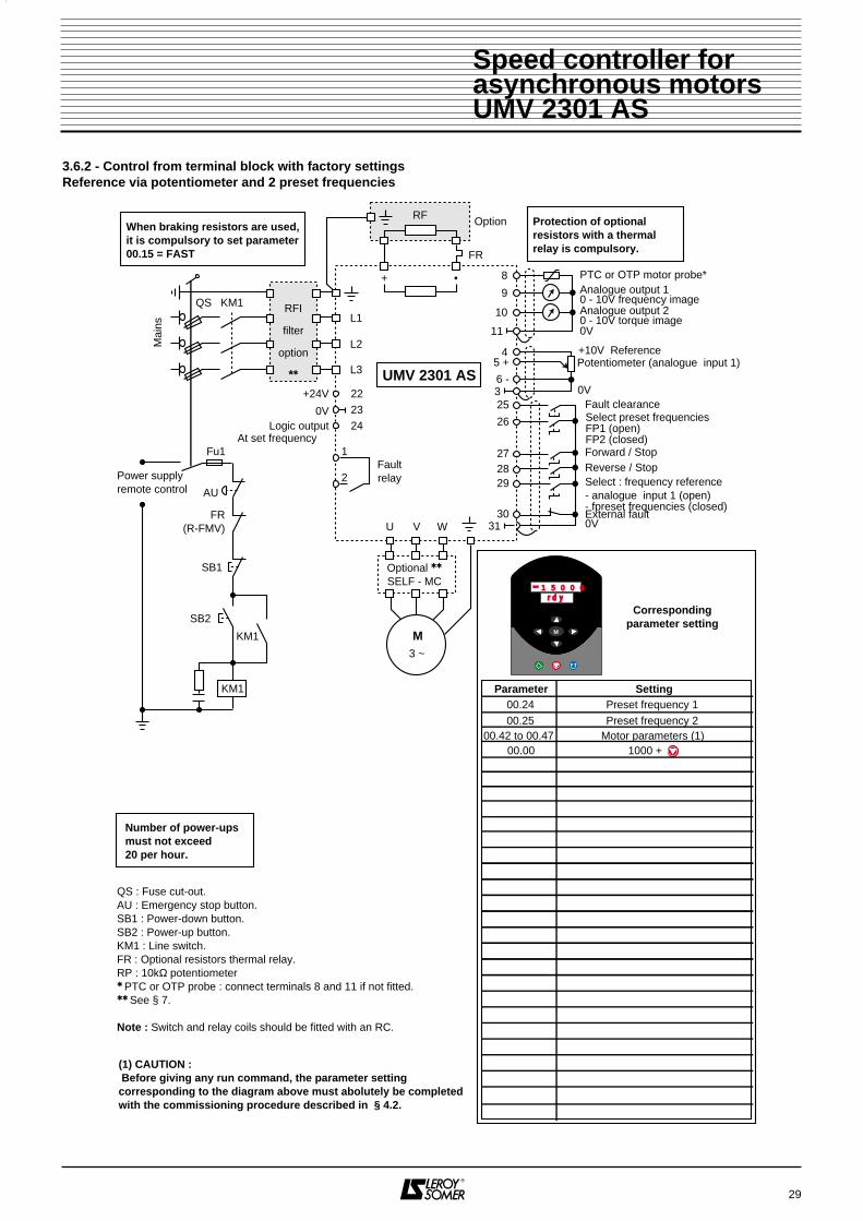
3.6.2 - Control from terminal block with factory settingsReference via potentiometer and 2 preset frequencies
1
2
U V W
M3 ~
AU
FR(R-FMV)
SB2
KM1
KM1
SB1
3
31
25
26
272829
30
Fu1
8+ •
11
9
10
RF Option
Power supplyremote control
Protection of optional resistors with a thermalrelay is compulsory.
Number of power-upsmust not exceed20 per hour.
FR
L1
L2
L3
Optional
SELF - MC
QS : Fuse cut-out.AU : Emergency stop button.SB1 : Power-down button.SB2 : Power-up button.KM1 : Line switch.FR : Optional resistors thermal relay.RP : 10kΩ potentiometer PTC or OTP probe : connect terminals 8 and 11 if not fitted. See § 7.
Note : Switch and relay coils should be fitted with an RC.
0V
45 +
6 -
PTC or OTP motor probe*Analogue output 10 - 10V frequency imageAnalogue output 20 - 10V torque image
+10V Reference
Forward / StopReverse / StopSelect : frequency reference - analogue input 1 (open)- fpreset frequencies (closed) 0V
Fault clearance
Potentiometer (analogue input 1)
0V
External fault
Select preset frequenciesFP1 (open)FP2 (closed)
Faultrelay
22+24V
0VLogic output
At set frequency
2324
When braking resistors are used,it is compulsory to set parameter00.15 = FAST
QS
Mai
ns
KM1 RFI
filter
option
** UMV 2301 AS
00.24 Preset frequency 100.25 Preset frequency 2
00.42 to 00.47 Motor parameters (1)00.00 1000 +
1 5 0 0 0r d y
M
Correspondingparameter setting
Parameter Setting
(1) CAUTION : Before giving any run command, the parameter settingcorresponding to the diagram above must abolutely be completedwith the commissioning procedure described in § 4.2.

30
Speed controller forasynchronous motorsUMV 2301 AS
3.6.3 - Control from terminal blockReference via analogue input and 4 preset frequencies
1
2
U V W
M3 ~
3
31
25
26
272829
30
8+ •
11
9
10
RF Option Protection of optional resistors with a thermalrelay is compulsory.
Number of power-upsmust not exceed20 per hou
FR
L1
L2
L3
Optional
SELF - MC
QS : Fuse cut-out.AU : Emergency stop button.SB1 : Power-down button.SB2 : Power-up button.KM1 : Line switch.FR : Optional resistors thermal relay.RP : 10kΩ potentiometer PTC or OTP probe : connect terminals 8 and 11 if not fitted. See § 7.
Note : Switch and relay coils should be fitted with an RC.
0V
5 +6 -
PTC or OTP motor probe*Analogue output 10 - 10V speed imageAnalogue output 20 - 10V torque image
Forward / StopReverse / StopSelect analoguereference / presetfrequencies (SR)
0V
Fault clearance
Analogue input 1(Differential mode,disconnect 6 and 3)
0V
External fault
Select presetfrequency (EFP1)
24 Select presetfrequency (EFP2)
Faultrelay
When braking resistors are used,it is compulsory to set parameter00.15 = FAST
AU
FR(R-FMV)
SB2
KM1
KM1
SB1
Fu1
Power supplyremote control
QS
Mai
ns
KM1 RFI
filter
option
**
Reference selection
SR EFP1 EFP2 Reference
Analogueinput 10 or 10 or 10
Presetfrequency 1001
Presetfrequency 2011
Presetfrequency 3101
Presetfrequency 4111
UMV 2301 AS
08.12 008.10 1.46
01.21
1000 +
01.22 Preset frequency 2Preset frequency 1
01.23 Preset frequency 301.24 Preset frequency 400.00
1 5 0 0 01 5 0 0 0
r d yr d y
M
Correspondingparameter setting
Parameter Setting
00.42 to 00.47 Motor parameters (1)00.00 149
(1) CAUTION : Before giving any run command, the parameter settingcorresponding to the diagram above must abolutely be completedwith the commissioning procedure described in § 4.2.
22+24V
0V 23

31
Speed controller forasynchronous motorsUMV 2301 AS
3.6.4 - Control from terminal blockReference via potentiometer (local control) or via analogue input (remote control )
1
2
U V W
M3 ~
AU
FR(R-FMV)
SB2
KM1
KM1
SB1
3
31
25
27
28
29
30
Fu1
8+ •
11
9
10
RF Option
Power supplyremote control
Protection of optional resistors with a thermalrelay is compulsory.
Number of power-upsmust not exceed20 per hour.
FR
L1
L2
L3
Optional
SELF - MC
QS : Fuse cut-out.AU : Emergency stop button.SB1 : Power-down button.SB2 : Power-up button.KM1 : Line switch.FR : Optional resistors thermal relay.RP : 10kΩ potentiometer PTC or OTP probe : connect terminals 8 and 11 if not fitted. See § 7.
Note : Switch and relay coils should be fitted with an RC.
45 +
6 -
PTC or OTP motor probe*Analogue output 10 - 10V frequency imageAnalogue output 20 - 10V torque image
Forward / Stop
Reverse / Stop
Select : frequency reference - analogue input 1 (open)- analogue input 2 (closed)
0V
Fault clearance
Analogue input 1(Differential mode)disconnect 6 and 3)Potentiometer input (Ana input 2)
0V
External fault
7
Faultrelay
22+24V
0VLogic output
At set frequency
2324
When braking resistors are used,it is compulsory to set parameter00.15 = FAST
QS
Mai
ns
KM1 RFI
filter
option
** UMV 2301 AS
08.23 1.4100.00 1000 +
1 5 0 0 01 5 0 0 0r d yr d y
M
Correspondingparameter setting
Parameter Setting
00.42 to 00.47 Motor parameters (1)00.00 149
(1) CAUTION : Before giving any run command, the parameter settingcorresponding to the diagram above must abolutely be completedwith the commissioning procedure described in § 4.2.

32
Speed controller forasynchronous motorsUMV 2301 AS
3.6.5 - Control from terminal blockSpeed reference via anamogue input or Faster / Slower command
1
2
U V W
M3 ~
AU
FR(R-FMV)
SB2
KM1
KM1
SB1
3
31
25
26272829
30
Fu1
8+ •
11
9
10
RF Option
Power supplyremote control
Protection of optional resistors with a thermalrelay is compulsory.
Number of power-upsmust not exceed20 per hour
FR
L1
L2
L3
Optional
SELF - MC
QS : Fuse cut-out.AU : Emergency stop button.SB1 : Power-down button.SB2 : Power-up button.KM1 : Line switch.FR : Optional resistors thermal relay.RP : 10kΩ potentiometer PTC or OTP probe : connect terminals 8 and 11 if not fitted. See § 7.
Note : Switch and relay coils should be fitted with an RC.
5 +6 -
PTC or OTP motor probe*Analogue output 10 - 10V speed imageAnalogue output 20 - 10V torque image
Forward / StopReverse / StopSelect speed referenceAnalogue input 1 (open)Faster/Slower command (closed)
0V
Fault clearanceFaster
Analogue input 1(Differential mode,disconnect 6 and 3)
0V
External fault
Slower
24
Faultrelay
When braking resistors are used,it is compulsory to set parameter00.15 = FAST
QS
Mai
ns
KM1 RFI
filter
option
** UMV 2301 AS
08.12 008.10 9.26
00.00 1000 +
08.16 9.2709.23 Faster/Slower ramp09.24 00.02 ÷ 100009.25 1.21
1 5 0 0 0r d y
M
Correspondingparameter setting
Parameter Setting
00.42 to 00.47 Motor parameters (1)00.00 149
(1) CAUTION : Before giving any run command, the parameter settingcorresponding to the diagram above must abolutely be completedwith the commissioning procedure described in § 4.2.
22+24V
0V 23

33
Speed controller forasynchronous motorsUMV 2301 AS
3.6.6 - Control from terminal blockPID loop with analogue reference
1
2
U V W
M3 ~
AU
FR(R-FMV)
SB2
KM1
KM1
SB1
31
25
27
2930
Fu1
8+ •
11
9
10
RF Option
Power supplyremote control
Protection of optional resistors with a thermalrelay is compulsory.
Number of power-upsmust not exceed20 per hour
FR
L1
L2
L3
Optional
SELF - MC
QS : Fuse cut-out.AU : Emergency stop button.SB1 : Power-down button.SB2 : Power-up button.KM1 : Line switch.FR : Optional resistors thermal relay.RP : 10kΩ potentiometer PTC or OTP probe : connect terminals 8 and 11 if not fitted. See § 7.
Note : Switch and relay coils should be fitted with an RC.
PTC or OTP motor probe*Analogue output 10 - 10V speed imageAnalogue output 20 - 10V torque image
Forward / Stop
0V
Fault clearance
0V
External fault
Faultrelay
22+24V
0VLogic output
At set frequency
2324 3
Sensor feedback (Ana. input 2)0V
7
45 +
6 -
+10V
PID reference (Ana. input 1)(In differential mode,disconnect 6 and 3)
When braking resistors are used,it is compulsory to set parameter00.15 = FAST
QS
Mai
ns
KM1 RFI
filter
option**
UMV 2301 AS
1 5 0 0 0r d y
M
Correspondingparameter setting
Parameter Setting
00.03 000.04 Min deceleration ramp
00.42 to 00.47 Motor parameters (1)
00.00 14900.02 Max. frequency + 10 %
14.04 1.28
14.03 1.2707.14 1.28
07.08 0.907.10 1.27
14.07 PID slew rate14.08 114.09 8.0414.10 Proportional gain (P)14.11 Integral gain (I)14.12 Derivative gain (D)14.13 High limit14.14 014.16 1.3600.00 1000 +
(1) CAUTION : Before giving any run command, the parameter settingcorresponding to the diagram above must abolutely be completedwith the commissioning procedure described in § 4.2.

34
Speed controller forasynchronous motorsUMV 2301 AS
3.6.7 - Control from terminal blockPID loop with 4 preset frequencies
1
2
U V W
M3 ~
AU
FR(R-FMV)
SB2
KM1
KM1
SB1
31
25
26
27
29
30
Fu1
8+ •
11
9
10
RF Option
Power supplyremote control
Protection of optional resistors with a thermalrelay is compulsory.
Number of power-upsmust not exceed20 per hour.
FR
L1
L2
L3
Optional
SELF - MC
QS : Fuse cut-out.AU : Emergency stop button.SB1 : Power-down button.SB2 : Power-up button.KM1 : Line switch.FR : Optional resistors thermal relay.RP : 10kΩ potentiometer PTC or OTP probe : connect terminals 8 and 11 if not fitted. See § 7.
Note : Switch and relay coils should be fitted with an RC.
PTC or OTP motor probe*Analogue output 10 - 10V speed imageAnalogue output 20 - 10V torque image
Forward / Stop
0V
Fault clearance
0V
External fault
6 -
Select presetreference (ERP1)
Select presetreference (ERP2)Fault
relay
22+24V
0V 23
3
Sensor feedback (Ana. input 1)0V
5+
When braking resistors are used,it is compulsory to set parameter00.15 = FAST
QS
Mai
ns
KM1 RFI
filter
option
**
1 5 0 0 0r d y
M
UMV 2301 AS
Correspondingparameter setting
Parameter Setting
00.03 000.04 Min deceleration ramp
01.14 300.42 to 00.47 Motor parameters (1)
01.21 Preset reference 101.22 Preset reference 201.23 Preset reference 301.24 Preset reference 4
00.00 14900.02 Max. frequency + 10 %
14.04 1.28
14.03 1.01
07.10 1.28
08.23 1.4609.04 10.0109.10 6.31
14.07 PID slew rate14.08 114.09 8.0414.10 Proportional gain (P)14.11 Integral gain (I)14.12 Derivative gain (D)14.13 High limit14.14 014.15 0.02 ÷ 40014.16 1.0500.00 1000 +
Select preset reference
ERP1 ERP2 Reference0 100 211 301 41
(1) CAUTION : Before giving any run command, the parameter settingcorresponding to the diagram above must abolutely be completedwith the commissioning procedure described in § 4.2.
Logic outputAt set frequency
24

4 - COMMISSIONING
• The controllers use a software, which is adjusted with parameters.• The performance level depends on the
parameter setting.• Incorrect settings may have severe
consequences for personnel and machinery.• The parameter setting of the controllers
should only be carried out by experienced andqualified personnel.
4.1 - Procedure for using the keypad 4.1.1 - PresentationAll keypads are identical and provide access toadjustment parameters and control of the drive.
Upper display consisting of six 7-segment display lines showing :
- operating mode,- parameter content,- trip code.
Lower display consisting of four 7-segment display lines showing :
- controller operation status,- adjustment parameters, consisting of the menu and theparameter.
1 mode key used for switching from normal toparameter mode (in parameter mode, the upper displayis flashing).
2 keys used for moving under the 7-seg-ment dipslay lines of the upper display, to modify the va-lues or switch to another menu.
2 keys used for scrolling parameters andto modify their value.
3 keys for implementing the follow-ing commands from the keypad :
(green key) : Run,
(red key) : Stop, Reset,
(blue key) : Reverse rotation.
4.1.2 - Adjustment parametersThe drive is configured for a given application using thesetting of parameters which are organized into menus.Each menu corresponds to a group of parametersorganized in specific functional groups.This manual describes the parameters in menu 0, whichincludes the essential parameters of the different menusbeing useful for a quick and simple starting-up in thedifferent standard operating modes.The other menus and parameters are protected by anaccess code.Access to the digital or bit (value 0 or 1) parameters ispossible :- either in « read only » mode (LS), for instance : speedimage or motor current image,- or in « read write » mode (LE), for instance : accelera-tion ramp.
35
8 8 8 8 8 88 8 8
M5
1
3
2
4
6
Speed controller forasynchronous motorsUMV 2301 AS
1
2
3
4
5
6
M

4.1.3 - Modification of parameters
36
Speed controller forasynchronous motorsUMV 2301 AS
Action Display Comments
Power-up of controller During 1 second after power-up, the upper display showsthe control mode which has been selected.
1 second after power-up Upper display shows motor speed
Switch to parametermode
Parameter 0.10 corresponds to motor speed
Access to the different pa-rameters
The key switches from a parameter to the next one.Content of parameters is shown on upper display.
The key switches from a parameter to the previousone
+simultaneously
Simultaneous action on the keys & provides immediate access to parameter 0 of the currentlyselected menu
Modification of a digitalparameter
Access to parameter 0.01
example : settingparameter 0.01( minimum speed) at 5Hz
Action on provides access to parameter 0.01
Move the cursor to the digit to be modified
5 x
Set to required value
Enter setting and leave content of parameter 0.01
Modification of bitparameter 8 x
Selection of dynamic V to F mode corresponds toparameter 0.09
Example : selection ofdynamic V to F mode
Access to content of parameter 0.09
Enable dynamic V to F mode by setting bit to 1
Enable selection and leave content
H V A Cr d Y
0r d Y
00. 0 0
0. 00. 0 1
b i t 10. 0 9
b i t 00. 0 9
b i t 00. 0 9
b i t 10. 0 9
5. 00. 0 1
5. 00. 0 1
0. 00. 0 1
0. 00. 0 1
00. 1 0
00. 1 1
00. 1 0
M
M
M
M
M
M

4.1.3 - Modification of parameters (end)
37
Speed controller forasynchronous motorsUMV 2301 AS
Action Display CommentsParameter memorizationwhen adjustments havebeen completed
+simultaneously
Go to parameter 0.00
Enter content of parameter 0.00
3 x
Move the cursor to the 4th digit from the right
Press key in order to show 1000 on upper display
Press red key to memorize all parameters
Switching to anothermenu
Enter into content of parameter 0.00
9 x
Display 9
Move the cursor to the digit located left of 9
4 x
Display 49
Move the cursor to the digit located left of 4
Display 149
Enable selection
The key switches to the next menu
The key switches to the previous menu
00. 0 0
00. 0 0
1 0 0 00. 0 0
1 4 90. 0 0
00. 0 0
01. 0 0
00. 0 0
9
1 0 0 00. 0 0
00. 0 0
Additional information- Without any operation on the console during 8s, the display returns to parameter 00.10 (motor speed).- A continuous action on keys and provides quick scrolling.
- 0
- 9
4 9
- 4 9
1 4 9
M
M
M

4.2 - Starting-up the controller
• Before the controller is powered up, make sure that all power connections are correct,
that motor connection is correct and that moving orrotating parts are mechanically protected.
• The users must be especially careful toavoid accidental starts of the controller.
4.2.1 - Reset functionNotice :Reset of the controller must be performed in thefollowing situations :• reset after controller trip,• after modification of operating mode,• when new values have been entered for certainparameters marked with .Enabling and memorization of new values can beperformed whilst the controller is running.- Procedure :• with the terminal block : close trip reset contact(terminal 25),• from keypad : press key when the controller is stopped ,• keep pressing run key and press reset key whilst the controller is running.
4.2.2 - Using parameter 00.00Before going back to factory settings , makesure that the safety of the system will not be
affected.
Set the following values for parameter 00.00 in order toget the functions listed hereunder :
4.2.3 - Selection of run command- From the keypad (see wiring diagram in § 3.6.1) : run,stop and speed control commands with the keys.- With the terminal block (see wiring diagram in § 3.6.2) :run, stop and speed control command with the terminalblock (connector).
4.2.4 - Programming motor parameters
• The values of the motor parameters affect motor protection and safety of system.• Set values of the parameters must be read on
the nameplate of the motor.• Motor parameters must be adjusted with a
minimum accuracy of 10% of rated values in order toachieve good performance.
Before programming a high speed, make sure that themotor and machinery can withstand it.( ) USA settings.
38
Speed controller forasynchronous motorsUMV 2301 AS
Setting of 00.00 Function Action
149 Access to other menus
1000Memorization of newvalues
1244Return to US factorysettings
1255Return to Europeanfactory settings
2000 Locked access to othermenus
Presson
reset
Parameter Setting/Display Description
0
Selection of analoguereference 1 or 2 withterminal 29
1Analogue speedreference 1
00.052
Analogue speedreference 2
3Preset frequencies
4Command from thekeypad
00.00 1000
Resetmemorization
Parameter Description Factorysetting
Adjustmenrange Unit
00.42 Nr of poles 4 2 to 24 Poles
00.43Power
factor (cos ϕ) 0.85 0 to 1.0 -
00.44Rated
motor voltage400
(460)0 to 480 V
00.45Rated
motor speed 0 0 to 6000 min-1
00.46Rated
motor currentImax
controll.0 to Imaxcontroller
A
00.47Rated
motor frequency50 (60) 0 to 1000 Hz
00.00 Memorization 0 1000 +
reset -

4.2.5 - Self-calibration of controller to motor
• During self-calibration phase, the controller powers the motor, thus causing it to rotate. • Make sure this operation does not affect
safety.
During self-calibration, the specifications of the motorare measured and the controller adapts automatically.
- Make sure that the motor is disconnected from its load.- Power up the controller.- Connect lock input (terminal 30) to terminal 0V(terminal 31).- Set value of parameter 00.40 to 1. The self-calibrationsequence begins.The motor accelerates up to half speed. The controllermeasures the magnetizing current, then decelerates andstops the motor. The value of the power factor ismeasured and automatically entered in parameter 00.43.Parameter 00.40 returns to 0.
4.2.6 - Control from the terminal block• Refer to diagram § 3.6.2.• Make at least the following connections :
• Set potentiometer at minimum level.• Leave terminal 29 open for the selection of analoguereference 1.• Power up the controller, the lower display shows " rdy ".• Display parameter 00.10 to read speed measurement.• Close the lock (terminal 30).• Give a run or reverse command (terminal 27 or 28).• Give a speed reference with the potentiometer. Theupper display shows speed in min-1.• Disable run command (by opening terminal 27 or 28),the motor decelerates and stops. The display shows« rdy ».
4.2.7 - Control from the keypad• Refer to diagram § 3.6.1.• Make at least the following connections
• Do not connect terminal 29 to 0V.• Close the lock (terminal 30) to 0V (terminal 31).• Power up the controller, the lower display shows " rdy ".• Set parameter 00.05 to 4 (selection of speed referencefrom keypad).• Display parameter 00.10 to read speed measurement.• Press key to start.• Wait until lower display shows « Run ». Press key to increase speed.
• Press key to reduce speed.
• Press key to reverse rotation.
• Press key to stop the motor, the display shows« rdy ».
Notice : to set the other parameters, refer to the open orclosed loop block diagrams on next pages, with thedescription of the parameters.
39
Speed controller forasynchronous motorsUMV 2301 AS
30
31
External fault0V
4
5
6
3
27
28
29
30
31
Analoguespeed
reference 1
Run Forward / Stop
Run Reverse / StopSelect : analogue input 1 (open) preset frequencies (closed)
External fault0V

4.3 - Menu 04.3.1 - Menu 0 block diagram
40
Speed controller forasynchronous motorsUMV 2301 AS
Optionalserial link
COM 1 UMV
Read and write
Read only
Read and assign
Symbols
00.11
00.32
00.33
00.48
00.50
Software version 2
Controller parameters
Frequencyclamps
Frequencyreference
before rampFrequencyskips
Rated current
Type of controller
Software version 1
00.34
00.38
00.49
User security code
Personalization
Default display
Security level
00.35
00.24Presetfrequency 1
00.25Presetfrequency 2
01.17Keypadreference
Not availablewith menu 0
Precisionreference
00.20 00.2200.21 00.23
00.02
00.36
00.37
"Two-wire" mode
Configuration of serial link
Data transmission speed
Address
00.02
00.01
5Analogueinput
1(differential)
Analogueinput
2
6
7
26
+
-
Type of signal
20-4mA tr
4-20mA Lo
20-4mA Lo
4-20mA Pr
20-4mA Pr
4-20mA tr
20-0mA
0-20mA
0-10V00.31
Stop mode
00.16
Selectspeed
reference
00.05
0 0
0
0
0
11
1
1
1
2
3
45
X - 1
1 2Skipband
29 27 28
Selectanalogueor presetreference
RunForw/Stop
RunRev /Stop
Coast
rP
tddcl
rPdc
dclDC
Coast stop
Ramp stop
Ramp and DC injection
DC injection
Timed DC injection
Selectpreset
frequencies

41
Speed controller forasynchronous motorsUMV 2301 AS
Read and write
Read only
Read and assign
Symbols
00.12
00.29
00.17
Currentloopgain
Currentlimits
Motorpower
00.47
00.46
00.45
Rated frequency
Motor parameters
Rated current
Rated speed
00.43
00.42
Cos ϕ
Pole number
00.44Rated voltage
Motor control
00.39
00.40
00.41
Catch spinning motor
Miscellaneous
Self-calibration procedure
Switching frequency
00.03
00.18
00.26
00.04
Acceleration Deceleration
RampsFrequencyreference
afterramp
Type of ramp
DC busvoltage
Boost V/F mode
Select control mode
Statorresistance
00.27
00.06
P
00.28I
00.13
00.14
Active current
Total current
Current measurement
UVW
00.19
00.15
Linearramp
"S"ramp
Regulation voltagethreshold
"S"ramprate
stnd Hd
Fast
stnd Ct
Automatic delay
Fixed period *
DC bus regulation
00.07
00.30
00.09
00.08
Deceleration mode
* With braking resistor
1
1
0
02
3
UrS
Ur1 Vector mode
Fixed V to F mode
Dynamic V/F mode
Ur
Fd
V/F mode type

42
Speed controller forasynchronous motorsUMV 2301 AS
4.3.2 - List over parameters in menu 0
Parameter Description Type Adjustment range Factory setting
00.00
MemorizationFactory SettingsAccess code to other menus
R - W
0 to 20001000 : memorization1244 : US factory settings1255 : Euro factory settings149 : Access code to other menus2000 : Locked access to other menus
0
00.01 Minimum frequency clamp R - W 0 to 1000.0 Hz 0.0 Hz
00.02 Maximum frequency clamp R - W 0 to 1000.0 Hz 50.0 Hz
00.03 Acceleration ramp R - W 0 to 3200.0s/100Hz 60.0s/100Hz
00.04 Deceleration ramp R - W 0 to 3200.0 s/100 Hz 60.0s/100Hz
00.05 Select speed references R - W 0 to 5 0
00.06 Current limits R - W 0 to 150% 120 %
00.07 Select control mode R - W Urs, Ur1, Ur, Fd Ur1
00.08 Starting torque (Boost) R - W 0 to 25 % 3.0 %
00.09 Select dynamic V to F mode R - W 0 - 1 1
00.10 Calculated motor speed RO 0 to ±60000 min-1 -
00.11 Pre-ramp speed reference RO 0 to ±1000.0 Hz -
00.12 Post-ramp speed reference RO 0 to ±1000.0 Hz -
00.13 Measurement of motor active current RO 0 to ± I max (A) -
00.14 Total motor active current R - W 0 to 400.0 Hz -
00.15 Select deceleration mode R - W Stnd.Ct, Stnd.Hd, FAST Stnd.Ct
00.16 Select stop mode R - W Coast, rp, rp.dc1, dc1, tdc1 rp
00.17 Motor power R - W (± I max x 00.44 x 3)/1000 -
00.18 Select linear ramp / S ramp R - W 0 - 1 0
00.19 S ramp rate R - W 0 to 3000.0 s2/100 Hz 450.0 s2
00.20 Frequency skip 1 R - W 0 to 1000.0 Hz 0.0
00.21 Frequency skip band 1 R - W 0 to 5,0 Hz 0,5 Hz
00.22 Frequency skip 2 R - W 0 to 1000.0 Hz 0.0
00.23 Frequency skip band 2 R - W 0 to 5,0 Hz 0.5 Hz
00.24 Preset frequency 1 R - W 0 to ± 1000.0 Hz 0.0 Hz
00.25 Preset frequency 2 R - W 0 to ± 1000.0 Hz 0.0 Hz
00.26 DC bus regulation voltage threshold R - W 0 to 800V 700 V
00.27 Current loop proportional gain R - W 0 to 4000 20
00.28 Current loop integral gain R - W 0 to 4000 40
00.29 DC bus voltage RO 0 to 830V -
00.30 Stator resistance R - W 0 à 32.000 Ω 0.000 Ω
00.31 Type of signal, analogue input 1 R - W
Volt, 0.20, 20.0, 4.20tr,20.4tr, 4.20 lo, 20.4lo,
4.20Pr, 20.4PrVolt
00.32 Software version 2 RO 1 to 99 -
00.33 Controller rated current RO 12.0 to 180.0A -

43
Speed controller forasynchronous motorsUMV 2301 AS
4.3.2 - List over parameters of menu 0
Parameter Description Type Adjustment range Factory setting
00.34 User security code R - W 0 to 255 149
00.35 Serial link : 2-wire mode R - W 0 or 1 0
00.36 Serial link transmission rate R - W 4800, 9600, 19200, Bauds 4800 Bauds
00.37 Serial link controller address R - W 0 to 9,9 1,1
00.38 Parameter displayed on power-up R - W 0 to 0.50 0.10
00.39 Catch spinning motor R - W 0 - 1 0
00.40 Self-calibration R - W 0 - 1 0
00.41 Switching frequency R - W 3 - 4,5 - 6 - 9 - 12 kHz 3 kHz
00.42 Motor pole number R - W 2 to 24 poles 4 poles
00.43 Power factor (cos ϕ) R - W 0 to 1.000 0,850
00.44 Motor rated voltage R - W 0 to 480 V 400 V
00.45 Motor rated speed R - W 0 to 6000.0 min-1 0
00.46 Motor rated current R - W 0 to IN. VAR. IN. VARIATEUR
00.47 Motor rated frequency R - W 0 to 1000.0 Hz 50.0 Hz
00.48 Controller operating mode RO - HVAC
00.49 Security status RO 0 - 1 / 0 - 1 / 0 - 1 0 / 0 / 1
00.50 Software version 1 RO 1.00 to 99.99Depending on software ver-
sion of product
See necessary derating § 1.3.2 depending on set frequency.

4.3.5 - Description of parameters in menu 0Symbols :
: Parameter for memorization, return toEuropean and US factory settings 149 : access to other menus,1000 : memorization,1244 : return to US factory settings,1253 : selection of operating mode,1255 : return to European factory settings,2000 : locked access to other menus.
: Minimum frequency clampRange : 0 to 1000.0 HzFactory setting : 0.0 HzIncrements of 0,1 Hz.It is the lowest operating frequency. With this parameterset to minimum value, it corresponds to output fre-quency.
: Maximum frequency clampRange : 0 to 1000.0 HzFactory setting : 50.0 HzIncrements of 0,1 Hz.It is the highest operating frequency. With this parameterset to maximum value, it corresponds to outputfrequency.
: Acceleration rampRange : 0 to 3200.0s/100HzFactory setting : 60.0s/100HzIncrements of 0,1s.Sets acceleration time from 0 to 100 Hz.
: Deceleration rampRange : 0 to 3200.0s/100HzFactory setting : 60.0s/100HzIncrements of 0,1s.Sets acceleration time from100 Hz to 0.
: Selection of speed referencesRange : 0 to 5.Factory setting : 0.Increments of 1.Used to choose speed reference.0 : Selection of analogue reference 1 or presetfrequencies.1 : Analogue speed reference 1 - differential input -terminals 5 and 6.2 : Analogue speed reference 2 - common mode input -terminals 7 and 11.3 : Preset speeds (not available with menu 0).4 : Selection of speed references from keypad.5 : Precision speed references (not available with menu0).
: Current limitation in motor and generatoroperating modes
Range : 0 to 120 % of In motorFactory setting : 120 %Increments of 1.Sets maximum current supplied from the controller inmotor and generator operating modes.When current limit is reached, output frequency isautomatically reduced.
: Selection of control modeRange : 0 to 3.Factory setting : 1.Increments of 1.0 : Urs : Vector control mode, stator resistancemeasured for each run command of the controller.1 : Ur1 : Vector control mode, stator resistancemeasured for each power-up of the controller.2 : Ur : Vector control mode, without stator resistancemeasurement.3 : Fd : V to F mode with adjustable fixed boost.
In mode 1 (Ur1), at power-up, a voltage is briefly applied to the motor without any run
command. For safety reasons, no electrical circuitshould be accessible as soon as the controller ispowered up.
44
00 00 .. 00 33
Speed controller forasynchronous motorsUMV 2301 AS
00 00 .. 00 00
00 00 .. 00 11
00 00 .. 00 22
F (Hz)
100 Hz
F2
F1
0
Value 00.03
tt (s)
00 00 .. 00 44
100 HzF (Hz)
F2
F1
0
Value 00.04
tt (s)
00 00 .. 00 55
00 00 .. 00 66
00 00 .. 00 77
Value of 00.03 (s) = t(s) x 100Hz(F2-F1) Hz
Value of 00.04 (s) = t(s) x 100Hz(F2-F1) min-1

CAUTION :During measurement of stator resistance, the motormust stand perfectly still. If stillness of motor cannotbe guaranteed at each power-up of the controller,mode 1 may be used for the first power-up and thenmode 2 should be used once the procedure hasbeen completed.Measurement of stator resistance allow optimizationof the motor / controller unit performances.
: Starting torque (Boost)Range : 0 to 25.0 % of Un motor (00.44).Factory setting : 3 % of Un motor.For operation in V to F mode, (00.07 at 3 : Fd) parameter00.08 sets the starting torque. It is a percentage of motorrated voltage (00.44).
CAUTION :If the set value is too high, the motor can becomenoisy and overheat.
: Selection of V to F dynamic modeRange : 0 to 1.Factory setting : 0.0 : U/F ratio is fixed and set by basic frequency (00.47).1 : U/F ratio is automatically adapted to motor load.The voltage applied to the motor is reducedaccording to the load. It is thus possible to spareenergy and reduce noise for low and variable loads.
: Measurement of motor speed
Range : -60.000 to +60.000 min-1
Motor speed in min-1. With standard setting, parameter00.10 is displayed as soon as the controller is powered-up.
: Frequency reference before ramp
Range : -1000.0 to +1000.0HzIncrements of 0,1 Hz.Measurement of set frequency before ramp. Used fordiagnosis.
: Frequency reference after ramp
Range : -1000.0 to +1000.0HzIncrements of 0,1 Hz.Measurement of set frequency after ramp. Used fordiagnosis.
: Measurement of motor active current
Range : - I max to + I max contr.The active current in the motor is the image of the torquein vector control mode.
: Measurement of total current
Range : 0 to I max contr.Gives effective current in each output phase of thecontroller.It corresponds to the vector sum of magnetizing currentand active current.
: Selection of deceleration modeRange : 0 to 2.Factory setting : 2.Increments of 1.0 : Stnd Hd - Standard deceleration ramp with time delayto avoid overvoltage tripping of DC bus.1 : FAST - Deceleration with fixed time up to currentlimit. With a driving load, a braking resistor option isnecessary.2 : Stnd Ct - Deceleration ramp with regulation of DCbus voltage and speed control, adapted for lightlyloaded machines and permitting a smootheroperation than with stnd.Hd setting.
45
Motorvoltage
00.44
00.47
Boost(00.08)
Motorfrequency
00.442
00.472
Speed controller forasynchronous motorsUMV 2301 AS
00 00 .. 00 88
00 00 .. 00 99
00 00 .. 11 55
00 00 .. 11 00
00 00 .. 11 11
00 00 .. 11 22
00 00 .. 11 33
00 00 .. 11 44

: Select stop mode Range : 0 to 4.Factory setting : 1 (rp).
0 (COAST) : Coast stopThe power bridge is desactivated when stop command isgiven. The controller cannot receive a new run commandduring 2s, corresponding to motor demagnetizing time.The display shows rdY 2s after run command. Themachine stop time depends on its inertia.
1 (rP) : Deceleration ramp stopThe controller decelerates the motor according todeceleration mode set with parameter 00.15.One second after stopping, the display shows rdY.
2 (rp.dcl) : Deceleration ramp stop with DC injectionduring 1sThe controller decelerates the motor according to thedeceleration mode set with parameter 00.15.When zero frequency is reached, the controller injectsDC in the motor during 1 second at a level specified byparameter 06.06. Then the display shows rdY.
3 (dcl.DC) : Stop after DC injection braking, with zerospeed detectionThe controller decelerates the motor by injecting DC at alevel specified by parameter 06.06 until it reaches a lowspeed which the controller automatically detects.The DC current is switched off 1 second after the motorhas stopped. Then the controller display shows rdY.
CAUTION : For efficient braking, value of parameter 06.06 mustbe set at 60 % minimum.
46
Speed controller forasynchronous motorsUMV 2301 AS
00 00 .. 11 66
Motorspeed
t
TimeCoast stop timeStop
Motorspeed
t
TimeDecelerationramp 1sec
StoprdY
Motorspeed
Motorcurrent
06.06
t
TimeDecelerationramp
Stop
DCinjection
1 secondMotor current
rdY
Motorspeed
Motorcurrent
06.06
t
TimeBrakingStop
DC injection
1 sec.
Motorcurrent
rdY

4 (td.dcl) : Timed DC injection braking stopThe controller decelerates the motor by injecting DC inthe motor at a level specified by parameter 06.06 for aperiod set with parameter 06.07, then the controllerdisplay shows rdY. No run command can be registeredas long as rdY is not displayed.
: Motor power
Range : ± (I max drive x 0.44 x 3) / 1000.Unit : kW.Measured active motor power.
: Selection of linear ramp / S rampRange : 0 to 1.Factory setting : 0.0 : The ramp is linear.1 : A radius (defined in 00.19) at beginning and end oframp avoids load balance.
: S ramp rateRange : 0 to 3000.0s2/100HzFactory setting : 450.0 s2
The value of 00.19 sets the maximum acceleration anddeceleration rate, from beginning to end of speedmodification. Compared with a linear ramp, the S rampincreases the global value of t, (t/2 at the beginning andthe end of the linear ramp).
: Frequency skip 1
: Frequency skip 2Range : 0 to 1000.0 HzFactory setting : 0.0 HzAllows to eliminate one or two motor operatingfrequencies which may cause mechanical resonance.If set to 0 the function is not activated.
: Frequency skip band 1
: Frequency skip band 2Range : 0 to 5,0 HzFactory setting : 0,5 Hz
: Preset frequency 1
: Preset frequency 2Range : 0 to ± 1000.0 HzFactory setting : 0.0 HzThese parameters allow to preset 2 frequencies.They can be used as references by commuting terminal29 to 1.Choice of preset frequency is achieved through terminal26.
47
Speed controller forasynchronous motorsUMV 2301 AS
Motorspeed
Motorcurrent
06.06
t
TimeBraking
Stop
DCinjectionMotor
current
rdY
00 00 .. 11 88
00 00 .. 11 99
Setspeed
Acceleration
Speed
t = (00.19) ÷ (00.03) for acceleration,t = (00.19) ÷ (00.04) for deceleration.
t2
t2
tt2
t2
t
00 00 .. 22 00
00 00 .. 22 22
00 00 .. 22 11
00 00 .. 22 33
F(Hz)
Frequencyreference
F2(00.22)
F1(00.20)
(00.21)
(00.23)
00 00 .. 22 44
00 00 .. 22 55
Status terminal 26 0 1
ReferencePreset frequency
1Preset frequency
2
00 00 .. 11 77

: DC bus regulation voltage thresholdRange : 0 to 800VFactory setting : 700VThis threshold is used when the controller is configuredin deceleration mode 0 (Stnd.Hd) or 2 (Stnd.Ct).In mode 0, should this threshold be set too low, thedeceleration ramp will not decrease and the machine willnot stop. If this threshold is set too high and there are noresistances connected, the controller will trip due to DCbus overvoltage (0V).In mode 0, should this threshold be set too low, thedeceleration ramp will not decrease and the machine willstop in coast mode. If this threshold is set too high andthere are no resistances connected, the controller willtrip due to DC bus overvoltage (0V).The minimum value of this parameter must be higherthan DC bus voltage obtained with maximum mainsvoltage. (V bus = V mains 2).
: Current loop proportional gain
: Current loop integral gainRange : 0 to 4000Factory setting : 00.27 = 20
00.28 = 40According to various internal factors of the controller,some oscillations may occur in the following situations :- Frequency regulation with current limitation aroundrated frequency and with load impacts.- Torque regulation on lightly loaded machines andaround rated speed.- Cutout of mains supply or on controlled decelerationramp when DC bus regulation is functioningTo reduce these oscillations, it is recommended :- first to increase proportional gain (00.27),- then to reduce integral gain (00.28).
: DC bus voltage
Range : 0 to 830Gives measurement of DC bus voltage.
: Stator resistanceRange : 0 to 32.000 ΩFactory setting : 0.000 ΩThis parameter memorizes motor stator resistance invector mode. It is measured according to mode selectedwith parameter 00.07.
: Type of signal on analogue input 1Range : 0 to 8Factory setting : 0The signal of analogue input 1 (terminals 5 and 6) canbe processed in different ways.0 (Volt) : Voltage input ± 10V.1 (0-20) : Current input 0 - 20mA.
2 (20-0) : Current input 20 - 0mA.3 (4-20.tr) : Current input 4 - 20mA with tripping onsignal loss.4 (20-4.tr) : Current input 20 - 4mA with tripping onsignal loss.5 (4-20.Lo) : Current input 4 - 20mA with setting atminimum speed reference on signal loss.6 (20-4.Lo) : Current input 20 - 4mA with setting atminimum speed reference on signal loss.7 (4-20.Pr) : Current input 4 - 20mA with keeping ofreference before tripping on signal loss.8 (20-4.Pr) : Current input 20 - 4mA with keeping ofreference before tripping on signal loss.
Note : For the modes 4 - 20mA and 20 - 4 mA, signalloss threshold is 3mA.
: Software version 2
Range : 1 to 99Indicates the third digit of software version installed inthe controller.Changes according to software modifications which doesnot affect the user.
: Controller rated current
Range : 12.0 to 180.0 AFactory setting : according to controller ratingThis parameter indicates controller rated voltage inpermanent operating mode.
: User security codeRange : 0 to 255Factory setting : 149It is possible with this parameter to enter a personalsecurity code which forbids any parameter modification.The personal code can only be read when it is edited. Inall other cases code 149 will be displayed.Do not use code 0.Access to the parameters is achieved by enteringselected personal code in parameter 0.00.
: Serial link, "2-wire" mode Range : 0 or 1Factory setting : 00 : 4-wire standard mode 1 : As used ANSI protocol is of " half duplex " type, it ispossible to connect Rx and Tx as well as RX and TXtogether and thus operate the serial link with only 2 dataconnections.
: Serial link transmission rateRange : 4800 Bauds, 9600 Bauds,
19200 BaudsFactory setting : 4800 Bauds
48
Speed controller forasynchronous motorsUMV 2301 AS
00 00 .. 22 66
00 00 .. 22 77
00 00 .. 22 88
00 00 .. 33 00
00 00 .. 33 11
00 00 .. 33 44
00 00 .. 33 55
00 00 .. 33 66
00 00 .. 22 99
00 00 .. 33 22
00 00 .. 33 33

: Controller serial link addressRange : 0 to 9,9Factory setting : 1,1
When an optional communication card " COM 1 UMV " isused, 00.37 specifies a controller address. The addressmust have the following format : 1.1 to 9.9.Do not use 0 as a group or controller address.
: Parameter displayed on power-up
Range : 0 to 00.50Factory setting : 00.10Defines which parameter is displayed when thecontroller is powered up.0.10 corresponds to motor speed.
: Enable catch spinning motor
Range : 0 or 1Factory setting : 1
0 : no catch spinning motor restart after fugitive cut-out.1 : catch spinning motor. After a fugitive cut-out ofthe mains, the controller measures the frequency ofthe remanent motor voltage in order to determine itsrotating speed. Thus the controller automaticallyreadjusts speed reference to actual motor speed.
• If the load stands still when run command isgiven or when mains supply is restored, this
operation can cause an unwanted rotation of themachine before the motor accelerates.
• Make sure this function does not affect safetyof personnel and machinery.
: Self-calibrationRange : 0 to 1.Factory setting : 0.1 : When started up for the first time, allowsmeasurement of motor data (magnetizing current, cos ϕ,etc…).This operation must be carried out with the motorunloaded. The controller accelerates the motor up to50% of rated speed and then stops.
• During the self-calibration phase, the controller powers the motor thus causing it to
rotate. Make sure this operation does not affectsafety.
: Switching frequencyRange : 3 - 4,5 - 6 - 9 - 12 kHzFactory setting : 3 kHz00.41 sets the PWM switching frequency as well as thesampling frequencies of the analogue and digital inputsaccording to the following table :
Switching frequencies of digital and analogue inputs• Condition A : - operation with frequency control.• Condition B :- operation with analogue input control by current signal.
Depending on switching frequency and rating of the UMV 2301 AS controller, it is necessary
to derate output current. Refer to table § 1.3.2.
: Motor polarityRange : 2 to 24 poles.Factory setting : 4 polesIncrements of 2.
: Motor rated power factor (cos ϕ)Range : 0 to 1,000Factory setting : 0,85Increments of 0,01.The cos ϕ value is automatically measured during self-calibration phase and set with the present parameter.
: Motor rated voltageRange : 0 to 480VFactory setting : 400VCorresponds to rated voltage stamped on motornameplate. Setting of the V to F rate.
: Motor rated speedRange : 0 to 6000.0 min-1
Factory setting : 0Increments of 1.Corresponds to motor speed under load for open loopoperation (see nameplate).
CAUTION :In certain situations and especially with very highinertial loads, a speed instability may occur around20 Hz. If this is the case, leave rated speed at 0.
49
Speed controller forasynchronous motorsUMV 2301 AS
00 00 .. 33 77
00 00 .. 33 88
00 00 .. 33 99
00 00 .. 44 00
00 00 .. 44 11
Switching frequencySetting Display Condition A Condition B
kHz kHz kHz0 3 3 31 4,5 4,5 2,22 6 6 33 9 4,5 2,254 12 6 3
00 00 .. 44 22
00 00 .. 44 33
Motor pole numberMotor rated speed
(min-1)2 30004 15006 10008 750
00 00 .. 44 44
00 00 .. 44 55

: Motor rated currentRange : 0 to In controllerFactory setting : In controllerCorresponds to current value stamped on motornameplate. Overload starts from this value.
: Motor rated frequencyRange : 0 to 1000.0 HzFactory setting : 50 HzIncrements of 0,1 Hz.Corresponds to the point where the motor operatingmode switches from constant torque to constant power.In standard operating mode, it corresponds to thefrequency stamped on motor nameplate.
: Selection of operating mode
Factory setting : HVACHVAC : Open loop operation in vector control modeor in V to F mode.
: Security status
Factory setting : 001Parameter 00.49 is composed of 3 digits anddeterminates parameter protection level.
: Software version 1
Range : 1.00 to 9.99Indicates the 2 first digits of the software versioninstalled in the controller.
50
Speed controller forasynchronous motorsUMV 2301 AS
00 00 .. 44 66
00 00 .. 44 77
X X XCode personnalizedwith 00.340 : No1 : Yes
Personnalized code enabled. Nomodification ofparameters is possible0 : No1 : Yes
Access to othermenus with code1490 : No1 : Yes
00 00 .. 44 88
00 00 .. 44 99
00 00 .. 55 00

51
Speed controller forasynchronous motorsUMV 2301 AS
4.4 - Fault processingThe controller has been factory configured for the most secure operation :- memorization of all faults,- fault clearance by voluntary action,- controlled start.However, depending on the application and on operating conditions, it is possible to control the operation as per the tablehereunder.
Parameter Function Setting DescriptionFactorysetting
06.02 Start mode diS The start is controlled. If run command is present at power-up, it will be necessary to perform stop command and thenrun in order to obtain the start
ALYS At power-up, start is automatic if the controller has nottripped and if run command is present
diSPd.dP At power-up, the controller will automatically start if the
drive was running when the power supply was cut out, andif run command is present. On the other hand, it will notstart if it was stopped when the power cut-out occurred.
06.03 Processing of microcuts diS When a microcut occurs, the controller keeps on driving aslong as the DC bus voltage is sufficient
StoP The controller detects the microcut and decelerates inorder to recover motor energy and thus maintain the DCbus voltage. When normal operating conditions arerestored, deceleration continues until the motor stops.
diS
ridE.th As before, but when normal conditions are restored, themotor reaccelerates up to set speed.
06.09 Catch spinning motor bit 0 When starting or after a microcut, the controller starts itsramp from 0.
1 The controller measures the frequency of the remanentvoltage in order to determine motor rotation speed anddirection and adjusts its reference to the measured value.
• if the motor is stopped, this function can cause unexpected rotation of the motor for a period of
1 or 2 seconds.
1
10.34 Number of automatic reset 0 After tripping, the controller waits for a clearance beforestarting again.
1 to 5 After tripping, the controller tries automatically to re-start asmany times as the programmed number. If the number ofrestartings has been completed within a 5 minute interval,the controller is locked.
0
10.35 Automatic restart time delay 0 to 25s Delay between a tripping and an automatic re-start. 110.36 Processing of fault relay bit 0 The fault relay gets to 0 between the fault occurrence and
the automatic restarting.bit 1 The fault relay remains at 1 between the fault occurrence
and the automatic restarting.0
10.37 Stop mode for minor faults bit 0 The controller initiates a coast stop for every fault.bit 1 When a minor fault occurs (fault 14 to 26 paragraph 5), the
controller decelerates before locking.0

52
Notes
Speed controller forasynchronous motorsUMV 2301 AS

53
4.5 - Other menusIn most cases, commissioning of the controller is possible with menu 0 or with the parameter settings given in specific diagrams.However, for particular applications, it could be interesting to have access to all the parameters of the controller. These aregrouped in menus and are expressed either in tables or in logic diagrams.
4.5.1 - MENU 1 : FREQUENCY REFERENCE : Selection, limitations and filters4.5.1.1 - Parameter list, Menu 1
Parameters also available in menu 0
Parameter Description Type Adjustment range UnitFactorysetting
User setting
01.01 Frequency reference before clamps RO ±1000,0 Hz - -01.02 Frequency reference before frequency skip RO ± min frequency to ± max frequency Hz - -01.03 Frequency reference before ramp RO ± min frequency to ± max frequency Hz - -01.04 Frequency reference offset R-W ±1000,0 Hz 001.05 Jog reference R-W 0 - 400,0 Hz 1,501.06 Maximum frequency clamp R-W 0-1000,0 Hz 50,001.07 Minimum frequency clamp R-W 0 to ± 01.06 Hz 001.08 Select negative minimum frequency R-W 0 or 1 - 001.09 Select frequency reference offset R-W 0 or 1 - 001.10 Select bipolar mode R-W 0 or 1 - 001.11 Run command flag RO 0 or 1 - - -01.12 Running direction flag RO 0 or 1 - - -01.13 Jog flag RO 0 or 1 - - -01.14 Select frequency references R-W 0 - 5 Code 001.15 Select preset frequencies R-W 0 - 9 Code 001.16 Preset reference timer R-W 0 - 400,0 s 10,0s01.17 Keypad reference R-W Min limit to max limit - 001.18 Precision reference (integral value) R-W ±1000,0 Hz 0,001.19 Precision reference (decimals) R-W 0,099 Hz 0,00001.20 Enable precision reference R-W 0 or 1 - 001.21 Preset frequency 1 R-W ±1000,0 Hz 001.22 Preset frequency 2 R-W ±1000,0 Hz 001.23 Preset frequency 3 R-W ±1000,0 Hz 001.24 Preset frequency 4 R-W ±1000,0 Hz 001.25 Preset frequency 5 R-W ±1000,0 Hz 001.26 Preset frequency 6 R-W ±1000,0 Hz 001.27 Preset frequency 7 R-W ±1000,0 Hz 001.28 Preset frequency 8 R-W ±1000,0 Hz 001.29 Frequency skip 1 R-W 0-1000,0 Hz 001.30 Frequency skip band 1 R-W 0-5,0 Hz 0,501.31 Frequency skip 2 R-W 0-1000 Hz 001.32 Frequency skip band 2 R-W 0-5,0 Hz 0,501.33 Frequency skip 3 R-W 0-1000,0 Hz 001.34 Frequency skip band 3 R-W 0-5,0 Hz 0,501.35 Frequency skip band flag RO 0 or 1 - - -01.36 Analogue frequency reference 1 R-A ±01.06 or -01.07 to +01.06 Hz - -01.37 Analogue frequency reference 2 R-A ±01.06 or -01.07 to +01.06 Hz - -01.38 Frequency reference percentage trim R-A ± 100,0 % - -01.41 Select reference via logic inputs R-A 0 or 1 - - -01.42 Select reference via logic inputs R-A 0 or 1 - - -01.43 Select reference via logic inputs R-A 0 or 1 - - -01.44 Select reference via logic inputs R-A 0 or 1 - - -01.45 Select reference via logic inputs R-A 0 or 1 - - -01.46 Select reference via logic inputs R-A 0 or 1 - - -01.47 Select reference via logic inputs R-A 0 or 1 - - -01.48 Timer reset flag R-W 0 or 1 - 0 -01.49 Selected reference indicator RO 1 - 5 Code - -01.50 Selected preset reference indicator RO 1 - 8 Code - -
Speed controller forasynchronous motorsUMV 2301 AS

4.5.1.2 - Block diagrams, Menu 1Selection of frequency reference
54
FP 1
Presetfrequencies
Preset frequencies cycle
FP 2
FP 3
FP 4
FP 5
FP 6
FP 7
FP 8
Keypadreference
Precisionreference
Integer valueDecimals
Select presetfrequency bit 0
Select presetfrequency bit 2
Select presetfrequency bit 1
Timed cycle
Cycle reset
Selectanalog. ref. 2
Select keypad
Selectpreset freq.
Selectprecision ref.
1
10
0
2
34
5
6
7
8 9
10
2
3
4
5
1
0
01.41
Select offset
Frequency referenceadjustment
Offset frequencyreference
Analoguereference1Analogue
reference 2
01.42
01.43
01.44
Read and write
Read only
Read and assign
Symbols
01.37
01.45
01.46
01.47
01.36
01.04
01.09
01.21
01.15
01.20
01.22
01.23
01.24
01.25
01.26
01.27
01.28
01.17
01.1801.19
Selectpreset
frequencies
01.14Selectfrequencyreferences
01.50 01.49
01.48
01.16
Frequencyreference
Select precisionreference
01.01
01.38Réf. +
Réf. x
100
FP1FP2FP3FP4FP5FP6FP7FP8
00001111
00110011
01010101
VP7
VP1
VP5
VP3
VP8
VP6
VP2
VP4
11 0
1 0
2
3
4
5
1 0
1 0
Memorization
Speed controller forasynchronous motorsUMV 2301 AS
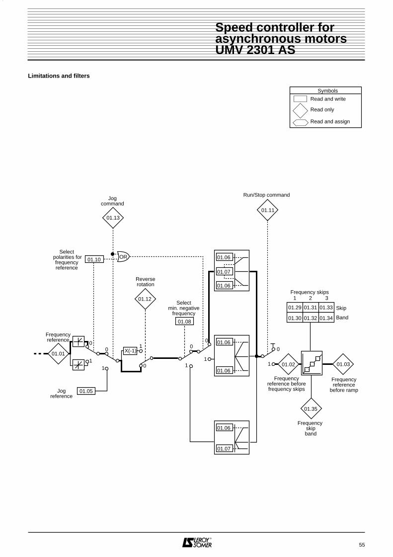
Limitations and filters
55
Jogcommand
01.29
01.30
01.31
01.32
01.33
01.3401.08
01.07
01.06
01.06
Selectmin. negative
frequency
Frequencyreference beforefrequency skips
Frequencyreference
before ramp
1 2 3
Frequency skipband
Read and write
Read only
Read and assign
Symbols
01.10
Select polarities for
frequencyreference
11
00
0
Frequencyreference
01.01
01.02
Jogreference
01.05
01.35
Reverserotation
1X(-1)
01.12
01.13
Run/Stop command
01.11
0
1 1
0
1
OR
01.06
01.06
01.06
01.07
01.03
Frequency skips
Skip
Band
0
Speed controller forasynchronous motorsUMV 2301 AS

4.5.1.3 - Description of parameters in menu 1
: Frequency reference before clamps
Range : ± 1000,0Sets the value of frequency reference.
& : Frequency referencebefore ramp
Range : ± min frequency to ± max frequency
01.02 : frequency reference after clamps but beforefrequency skips.01.03 : frequency reference after frequency skips butbefore acceleration or deceleration ramps.
: Frequency reference offsetRange : ± 1000,0 HzFactory setting : 0 HzThis reference is added to selected reference ifparameter 01.09 is set to 1. It can be used to adjustselected main reference in order to have a precisesetting.
: Jog referenceRange : 0 - 400,0 HzFactory setting : 1,5 HzFrequency reference used for jogging.
: Maximum frequency clampRange : 0 - 1000,0 HzFactory setting : 50,0 HzIf parameter 01.08 is set to 0, this parameter sets themaximum frequency in both running directions. If parameter 01.08 is set to 1 it is the maximumfrequency in forward operation only.Sets maximum frequency. Slip compensation canincrease the output frequency further.
: Minimum frequency clampRange : If 01.08 = 0 : 0 to 01.06
If 01.08 = 1 : 0 to -1000 HzFactory setting : 0 HzIf parameter 01.08 is set to 0, this parameter sets theminimum frequency in unipolar mode.Inactive parameter when operating in jog mode orbipolar mode.If parameter 01.08 is set to 1, this parameter sets thenegative minimum frequency in reverse operation.
: Select negative minimumfrequency
Range : 0 or 1Factory setting : 0
0 : minimum frequency (01.07) can be between 0 andthe maximum clamp. In this case, the referencevariation range will be between 01.07 and 01.06 inforward operation and -01.07 and -01.06 in reverseoperation.CAUTION : Operation in jog mode or bipolar modedisables the minimum clamp.
1 : parameter 01.07 is used as maximum limit in reverseoperation. The reference variation range is thus 01.07 inreverse operation and 01.06 in forward operation.
: Select frequency reference offsetRange : 0 or 1Factory setting : 00 : the frequency reference offset added to selectedreference corresponds to the percentage trimspecified by parameter 01.38.1 : the offset has the value of reference offset (01.04).
: Select bipolar mode Range : 0 ou 1Factory setting : 00 : all negative references are treated as zero.1 : allows to change running direction through referencepolarity.
to : Drive control flags
Range : 0 or 1These flags allow to control the enabling of runcommands.01.11 : 0 = Stop
1 = Run01.12 : 0 = Run forward
1 = Run reverse01.13 : 1 = Enable jog operation.
56
00 11 .. 00 11
00 11 .. 00 44
00 11 .. 00 22 00 11 .. 00 33
00 11 .. 00 55
00 11 .. 00 66
00 11 .. 00 77
00 11 .. 00 88
00 11 .. 00 99
00 11 .. 11 00
00 11 .. 11 11 00 11 .. 11 33
Speed controller forasynchronous motorsUMV 2301 AS

: Select frequency referencesRange : 0 - 5Factory setting : 0This parameter is used to select frequency reference asfollows : 0 : Select reference by logic terminal inputs1 : Analogue reference 1 selected2 : Analogue reference 2 selected3 : Preset frequencies selected4 : Keypad reference selected5 : Precision reference selectedWhen this parameter is set to 0, the consideredreference depends on the state of bit parameters 01.41to 01.44.
: Select analogue reference 2
: Select preset frequencies
: Select keypad reference
: Select precision reference- If all these parameters are set to 0, analogue reference1 will be selected.- If at least one of these parameters is set to 1, thehighest parameter will have priority.
: Select preset frequenciesRange : 0 - 9Factory setting : 0This parameter is used to select preset frequencies. iItworks as follows : 0 : Select preset frequencies by logic terminal inputs1 : Preset frequency 1 selected2 : Preset frequency 2 selected3 : Preset frequency 3 selected4 : Preset frequency 4 selected5 : Preset frequency 5 selected6 : Preset frequency 6 selected7 : Preset frequency 7 selected8 : Preset frequency 8 selected9 : Preset frequencies automatically selected by timerWhen this parameter is set to 0, requested presetfrequency is selected according to state of bitparameters 01.45 to 01.47.Selection operates according to the table below.
When this parameter is set to 9, the controllerautomatically selects in turn FP1 --> FP2 ------ FP7 -->FP8 --> FP1 ------. Parameter 01.16 allows setting ofswitching time from a frequency to another.
: Preset frequencies reference timerRange : 0 - 400,0sFactory setting : 10,0sWhen an automatic cycle is selected (01.15 = 9), thisparameter sets switching time from a preset frequency toanother. When parameter 01.48 gets to 1, the cyclesystem is reset to 0 and preset frequency 1 is selected.
: Reference setting via keypadRange :
Factory setting : 0This parameter is used to adjust the reference whensetting via keypad is selected (01.14 = 4). Key D isused to increase the reference and key E todecrease it.The speed reference value is saved on power down so itis automatically reset when the drive is powered-upagain.
, : Precision referenceRange : 01.18 : ± 1000,0 Hz
01.19 : 0 - 0.099 HzFactory setting : 01.18 : 0,0 Hz
01.19 : 0,000 HzAs standard, the frequency reference cannot have aresolution better than 0,03 Hz. The use of the precisionreference allows to reach a resolution of 0,001 Hz. Inthat case 01.18 allows to set the integral value of thereference, and 01.19 the decimals.
: Enable precision referenceRange : 0 or 1Factory setting : 0As the precision reference is set with 2 parameters,01.20 is used to prevent the drive reading theparameters while the reference is being updated.0 : The precision reference is stored in a memory.1 : The precision reference is enabled.
to : Preset frequenciesRange : ± 1000,0 HzFactory setting : 0 HzIn that order, 01.21 to 01.28 are used to adjust presetfrequencies FP1 to FP8.
57
00 11 .. 11 44
00 11 .. 44 11
00 11 .. 44 22
00 11 .. 44 33
00 11 .. 44 44
01.45 01.46 01.47Selected preset
frequency0 0 0 11 0 0 20 1 0 31 1 0 40 0 1 51 0 1 60 1 1 71 1 1 8
00 11 .. 11 55
00 11 .. 11 66
01.08 01.10 Range
0 0 01.07to 01.06 (01.07>0)0 1 ± 01.061 0 0 to 01.061 1 01.07 to 01.06 (01.07≤0)
00 11 .. 11 77
00 11 .. 11 88 00 11 .. 11 99
00 11 .. 22 00
00 11 .. 22 11 00 11 .. 22 88
Speed controller forasynchronous motorsUMV 2301 AS

, : Frequency skips
Range : 0 - 1000,0 HzFactory setting : 0 HzThree frequency skips are available to prevent operationat critical speeds that would cause mechanical resonan-ce of the machine. When a parameter is set to 0, thefunction is inactive.
, : Frequency skip bands
Range : 0 - 5,0 HzFactory setting : 0,5 HzThese parameters set the frequency range around theavoided frequency. The total frequency skip is thus equalto the set threshold ± skip band.
: Frequency skip band flag
Range : 0 or 1This parameter is set to 1when the selected reference iswithin one of the frequency skip regions.In that case motor speed does not correspond todemanded reference.
: Analogue references 1 and 2
Range : 01.08 = 0 : ± 01.06 Hz 01.08 = 1 :- 01.07 to +01.06Hz
The analogue inputs assigned to these parameters areautomatically scaled so that 100,0 % of the inputcorresponds to the maximal set frequency. Likewise 0 %will correspond to the minimal reference (01.07).Unipolar mode (01.08 = 01.10 = 0)
Bipolar mode (01.10 = 1)
01.08 = 0, R max = 01.06.01.08 = 1, R max = 01.06 or 01.07 which ever is greater.
: Frequency reference percentage trimRange : ± 100,0 %An offset proportional to selected reference can beadded to this reference. The trim factor depends on theanalogue input routed to parameter 01.38.Final ref (01.01) = selected ref x (1 + ).
to : Select reference via logic inputs
Range : 0 or 1These parameters are used to control selection of thereference via logic inputs (see parameters 01.14 and01.15)01.41 : Select analogue reference 201.42 : Select preset frequencies01.43 : Select reference via keypad 01.44 : Select precision reference 01.45 : Select bit 0 preset frequencies01.46 : Select bit 1 preset frequencies01.47 : Select bit 2 preset frequencies
: Timer reset flagRange : 0 or 1Factory setting : 0When this parameter is set to 1, the preset frequencytimer is reset to 0 (01.15 = 9), such that preset frequency1 is selected. This parameter can be used to start a newsequence of speed selection via programmable logicinput.
: Selected reference indicator
Range : 1 - 5Shows which reference is currently being selected.
: Selected preset reference indicator
Range : 1 - 8Shows which preset reference is currently beingselected.
58
00 11 .. 33 55
00 11 .. 33 66
00 11 .. 22 99 00 11 .. 33 11
00 11 .. 33 33
00 11 .. 33 00 00 11 .. 33 22
00 11 .. 33 44
00 11 .. 33 77
Reference
01.06
01.07
0100,0 %
Reference
R max
- 100,0
+ 100,0
%
- R max
00 11 .. 33 88
100
00 11 .. 33 88
00 11 .. 44 88
00 11 .. 44 11 00 11 .. 44 77
00 11 .. 44 99
00 11 .. 55 00
Speed controller forasynchronous motorsUMV 2301 AS

59
4.5.2 - MENU 6 : PROCESSING OF LOGIC COMMANDS AND METERS4.5.2.1 - List over parameters in Menu 6
Parameters also available in menu 0
Parameter Description Type Adjustmentrange Unit Factory
settingUser
setting
06.01 Select stop mode R-W 0 to 4 Code 106.02 Automatic start mode R-W 0 to 2 Code 006.03 Mains loss mode R-W 0 to 2 Code 006.04 Assignment and processing of logic commands R-W 0 to 4 Code 406.05 Minimum jog time R-W 0,0 to 25,0 s 1
06.06 DC injection braking level R-W0,0 to maxcurrent limit % 100,0
06.07 DC injection braking time R-W 0,0 to 25,0 s 5,006.08 Hold zero speed R-W 0 or 1 - 0 06.09 Enable catch spinning motor R-W 0 or 1 - 0 06.10 Spinning motor ramp rate R-W 0 to 25,0 s/100 Hz 5,006.11 Enable keypad Run key R-W 0 or 1 - 006.12 Enable keypad Stop key R-W 0 or 1 - 006.13 Enable keypad Forward / Reverse key R-W 0 or 1 - 006.14 Disable automatic selection of keys R-W 0 or 1 - 006.15 Drive enable R-W 0 or 1 - 106.16 kWh cost R-W 0,0 to 300,00 currency / kWh 006.17 Reset power meter R-W 0 or 1 - 006.18 Running time before alarm 1 R-W 0 to 30000 h 006.19 Alarm 1 and meter reset R-W 0 or 1 - 006.20 Running time before alarm 2 R-W 0 to 30000 h 006.21 Alarm 2 and meter reset R-W 0 or 1 - 0
06.22 Time counter (years and days) RO0,000 to30,365 Years/days - -
06.23 Time counter (hours and minutes) RO 0,00 to 23,59 h / mn - -06.24 Power meter (MWh) RO 0 to 30000 MWh - -06.25 Power meter (kWh) RO 0,0 to 999,9 kWh - -06.26 Running cost RO 0,00 to 300,00 currency / hour - -06.27 Time before alarm 1 RO 0 to 30000 h - -06.28 Time before alarm 2 RO 0 to 30000 h - -06.29 Hardware enable RO 0 or 1 - - -06.30 Sequencing bit 0 logic commands R-A 0 or 1 - 006.31 Sequencing bit 1 logic commands R-A 0 or 1 - 006.32 Sequencing bit 2 logic commands R-A 0 or 1 - 006.33 Sequencing bit 3 logic commands R-A 0 or 1 - 006.34 Assignment of Run / Stop terminal R-A 0 or 1 - 006.35 Forward limit switch input R-A 0 or 1 - - -06.36 Reverse limit switch input R-A 0 or 1 - - -
06.37Spinning motor start voltage
R-W 0 to 100,0% of rated vol-
tage 25,0
06.38 Spinning motor voltage ramp R-W 0 to 2,50 s 0,25
Speed controller forasynchronous motorsUMV 2301 AS

4.5.2.2 - Block diagrams Menu 6Processing of logic commands
60
Read and write
Read only
Read and assign
Symbols
EnableForw/Rev
key
EnableStopkey
EnableRunkey8 8 8 8 8 8
8 8 8 8 8 8
8 8 8
8 8 8
M
1
1
0
0
1
0
06.13 06.12 06.11
06.04
0106.14
Disablekeypad
auto selection
Selectkeypad reference
Menu 1
Unlock
Automatic start mode
Minimum jog time
Start processing
06.15
06.02
06.05
Mains loss mode
Catch spinning motor
Spinning motor ramp rate
Spinning motor start voltage
Spinning motor voltage ramp
Microcut processing
06.03
06.09
06.10
06.37
06.38
Stop mode
Hold zero speed
DC braking level
DC braking time
Limit switch input forward
Limit switch input reverse
Stop processing
06.01
06.08
06.06
06.07
06.35
06.36
Processing
of logic
commands
Enable keypad Configuration of terminals
25
2601.45
10.33
06.30 27
06.32 28
2901.42
06.29 30
31
Clear / faultFP1/FP2
Run forward / StopRun reverse / StopSelect : ana input 1/
presetfrequencies
Unlock
25
2606.31
10.33
06.30 27
06.32 28
2906.34
06.29 30
31
Clear / fault
Jog
RunReverse running direction
Enable Run/Stop
Unlock
25
2606.31
10.33
06.30 27
06.32 28
2906.34
06.34
06.29 30
31
Clear / fault
Jog forward
Run forward
Run reverseEnable Run/Stop
Unlock
25
2606.31
10.33
06.30 27
06.32 28
29
06.29 30
31
Clear / fault
Jog
Run forward / Stop
Run reverse / Stop
Coast stopUnlock
25
2606.31
10.33
06.30 27
06.32 28
29
06.29 30
31
Clear / fault
Jog
Run / Stop
Unlock
Reverse running direction
0
4
1
3
2
Assignment & processingof commands
Speed controller forasynchronous motorsUMV 2301 AS

Time counter, power meter and alarms
61
Delay before alarm 1
Alarm 1 and reset meter
Alarm 2 and reset meter
Delay before alarm 2
Read and write
Read only
Read and assign
Symbols
06.23 06.22
01.11
Run / Stop command
Clock
06.17
06.16
06.19
Time counterHours
MinutesYearsDays
06.25
05.03
06.24
Power meterKWh MWh
Resetpowermeter
KWh cost
Motorpower
06.26Running hourcost
06.27
Menu 5 X
06.18
Running periodbefore alarm 1
Running periodbefore alarm 2
X
0
1
0
1
06.21
06.28
06.20
Speed controller forasynchronous motorsUMV 2301 AS

4.5.2.3 - Description of parameters in menu 6
: Select stop mode Range : 0 to 4.Factory setting : 1 (rp).
0 (COAST) : Coast stopThe power bridge is desactivated when stop command isgiven. The controller cannot receive a new run commandduring 2s, corresponding to motor demagnetizing time.The display shows rdY 2s after run command. Themachine stop time depends on its inertia.
1 (rP) : Deceleration ramp stopThe controller decelerates the motor according todeceleration mode set with parameter 00.15.One second after stopping, the display shows rdY.
2 (rp.dcl) : Deceleration ramp stop with 1 second DCinjectionThe controller decelerates the motor according to thedeceleration mode set with parameter 00.15.When zero frequency is reached, the controller injectsDC in the motor during 1 second at a level specified byparameter 06.06. Then the display shows rdY.
3 (dcl.DC) : DC injection braking stop with detection ofzero speedThe controller decelerates the motor by injecting DC at alevel specified by parameter 06.06 until it reaches a lowspeed which the controller detects automatically.The DC current is switched off 1 second after the motorhas stopped. Then the controller display shows rdY.
CAUTION : For efficient braking, value of parameter 06.06 mustbe set to 60 % minimum.
62
Motorspeed
t
TimeCoast stop timeStop
Motorspeed
t
TimeDecelerationramp 1sec
StoprdY
Motorspeed
Motorcurrent
06.06
t
TimeDecelerationramp
Stop
DCinjection
1 secondMotor current
rdY
Motorspeed
Motorcurrent
06.06
t
TimeBrakingStop
DC injection
1 sec.
Motorcurrent
rdY
00 66 .. 00 11
Speed controller forasynchronous motorsUMV 2301 AS

4 (td.dcl) : Stop after DC injection braking with fixed timeThe controller decelerates the motor by injecting DC at alevel specified by parameter 06.06 for a period set withparameter 06.07, then the controller display shows rdY.No run command can be registered as long as rdY is notdisplayed.
: Automatic start modeRange : 0 to 2Factory setting : 0This parameter can be set to the 3 following values :
0 (diS) : Start is commanded. If the run command ispresent at power-up, it will be necessary tocommand Stop and then Run to start the drive.1 (ALYS) : Start is automatic at power-up if the controlleris not in trip mode and if the Run command is present.2 (PddP) : The controller will start automatically atpower-up if it was running when the mains power supplywas cut out and if the Run command is present. It willnot start if it was stopped when the mains power supplywas cut out.CAUTION :This parameter is not operational if 06.04 = 2 - 3 or 4because for these 3 modes, the Run inputs mustremain enabled to keep the controller running.
: Mains loss modeRange : 0 to 2Factory setting : 0This parameter can be set at the 3 following values :
0 (diS) : When a microcut occurs, the controllerkeeps on running as long as the DC bus voltage issufficient1 (Stop) : The controller detects the microcut and startsto decelerate in order to recover motor energy andmaintain DC bus voltage. When normal conditions arerestored, deceleration is maintained until the motor stops
2 (ridE.th) : Ride through. Like before but when normalconditions are restored, the motor accelerates again toset speed.
: Assignment and processing of logic commands
Range : 0 to 4Factory setting : 45 logic command processing modes are available. Theconfiguration of the terminal block for each value of06.04 is given in paragraph 6.5.2.0 : See terminal block configuration § 4.5.2.2 : 06.04 = 0The Forward/Reverse and Run keys of the keypad havepriority over terminals 27 and 28, provided they areenabled.1 : See terminal block configuration § 4.5.2.2 : 06.04 = 1The Forward/Reverse and Run keys of the keypadoperate provided they are enabled, but terminals 27 and28 have priority.2 : See terminal block configuration § 4.5.2.2 : 06.04 = 2In this mode, the terminals must be permanently madeactive to remain enabled. The Forward/Reverse and Runkeys of the keypad are thus not available.3 : See terminal block configuration § 4.5.2.2 : 06.04 = 3In this mode, the terminals must be permanently madeactive to remain enabled. The Forward/Reverse and Runkeys of the keypad are thus not available.4 : See terminal block configuration § 4.5.2.2 : 06.04 = 4In this mode, terminals must be permanently madeactive to remain enabled. Forward / Reverse andRun keys of the controller are thus not available.CAUTION : If 06.04 = 0, 1 or 2, parameter 08.23should be set at 06.34.
63
Motorspeed
Motorcurrent
06.06
t
TimeBraking
Stop
DCinjectionMotor
current
rdY
00 66 .. 00 22
00 66 .. 00 33
0 diS When changing status
1 ALYS Automatically at power-up
2 PddP According to status when powered down
0 diS Not sensitive to microcuts
1 StoP Deceleration until stopping
2 ridE.th Deceleration until the mains is restored
00 66 .. 00 44
Speed controller forasynchronous motorsUMV 2301 AS

: Minimum jog timeRange : 0,0 to 25,0sFactory setting : 1s
This parameter can be used to set a minimum jog timecorresponding to a pulse on a "jog" input.This parameter is not operational if 06.04 = 2 - 3 or 4.
: DC injection braking level Range : 0,0 to I max controller.Factory setting : 100,0 %This parameter sets the current level used for DCinjection braking.The current limit is given hereafter :
150,0 x
: DC injection braking time Range : 0,0 to 25,0sFactory setting : 5,0sThis parameter sets the low frequency current injectionbraking time when 06.01 = td-dcl.
: Hold zero speedRange : 0 or 1Factory setting : 0When this parameter is set to 1, the controller will holdtorque at standstill following a stop command instead ofdisabling the output bridge. Controller status will be"StoP" when it has stopped rather than " rdY ".
: Enable catch spinning motorRange : 0 or 1Factory setting : 1
0 : no spin restart after fugitive cut-out.1 : spin restart. After a fugitive cut-out of the mains,the controller measures the frequency of theremanent motor voltage in order to determine itsrotating speed. Thus the controller automaticallyreadjusts speed reference to actual motor speed.
• If the load is stationary when run command is given or when mains supply is restored, this
operation can cause an unwanted rotation of themachine before the motor accelerates.
• Make sure this function does not affect safetyof personnel and machinery.
: Spinning motor ramp rateRange : 0 to 25,0 s / 100 HzFactory setting : 5,0 s / 100 HzThis parameter sets the frequency ramp rate during thespin restart test.A low value should be set for applications with smallinertial load in order to have a precise speed detection.Set a higher value for applications with high inertial loadin order to prevent overvoltage trip.
: Enable keypad Run key Range : 0 or 1Factory setting : 0This parameter enables the "Run" key of the keypad.Default setting of this parameter will automatically be 1when keypad reference is selected and 0 otherwise.Automatic enabling of the "Run" key can be forbiddenwith parameter 06.14.0 : Run key disabled.1 : Run key enabled.
: Enable keypad Stop keyRange : 0 or 1Factory setting : 0This parameter enables the "Stop" key of the keypad.Default setting of this parameter will automatically be 1when keypad reference is selected and 0 otherwise.Automatic enabling of the "Stop" key can be forbiddenwith parameter 06.14.0 : Stop key disabled.1 : Stop key enabled.
: Enable keypad Forward / Reverse key Range : 0 or 1Factory setting : 0This parameter enables the "Forward / Reverse" key ofthe keypad. Default setting of this parameter willautomatically be 1 when keypad reference is selectedand 0 otherwise. Automatic enabling of the "Forward /Reverse" key can be forbidden with parameter 06.14.0 : Forward / Reverse key disabled.1 : Forward / Reverse key enabled.
: Disable automatic selection of keys
Range : 0 or 1Factory setting : 00 : Automatic enabling of keys is allowed.1 : The keys are not automatically enabled when keypadreference is selected. The keys can be individuallyenabled with parameters 06.11 to 06.13.
: Drive enable Range : 0 or 1Factory setting : 10 : Controller enabled.1 : Controller disabled.
: kWh costRange : 0,0 to 300,00 currency/kWhFactory setting : 0 currency/kWhWhen this parameter is set correctly for local currency,parameter 06.26 will allow immediate reading of runningcosts.
64
00 66 .. 00 55
00 66 .. 00 66
controller rated currentmotor rated current
00 66 .. 00 77
00 66 .. 00 88
00 66 .. 00 99
00 66 .. 11 00
00 66 .. 11 11
00 66 .. 11 22
00 66 .. 11 33
00 66 .. 11 44
00 66 .. 11 55
00 66 .. 11 66
Speed controller forasynchronous motorsUMV 2301 AS

: Reset power meterRange : 0 or 1Factory setting : 0When this parameter is set to 1, parameters 06.24 and06.25 are reset to 0.
: Running time before alarm 1Range : 0 to 30000hFactory setting : 0hThis parameter sets running time before alarm release.
: Alarm 1 and meter resetRange : 0 or 1Factory setting : 0This parameter is set to 1 when running time beforealarm 1 has run out.If this parameter is reset to 0, the meter is reset to itsinitial value (06.18).
: Running time before alarm 2Range : 0 to 30000hFactory setting : 0hThis parameter sets running time before alarm release.
: Alarm 2 and meter resetRange : 0 or 1Factory setting : 0This parameter is set to 1 when running time beforealarm 2 has run out.If this parameter is reset to 0, the meter is reset to itsinitial value (06.20).
: Time counter (years and days)
Range : 0,000 to 30,365 years, daysThis parameter records running years and days sincefirst start-up of the controller.
: Time counter (hours and minutes)
Range : 0,00 to 23,59 h, minThis parameter records running years and days sincefirst start-up of the controller.After 23h59 min, 06.23 is reset to 0 and 06.22 isincremented with 1 day.
: Power meter (MWh)
Range : 0 to 30000 MWhThis parameter records the power consumption of thecontroller expressed in MWh.This meter can be reset to 0 by setting parameter 06.17to 1.
: Power meter (kWh)
Range : 0,0 to 999,9 kWhThis parameter records the power consumption of thecontroller expressed in kWh.This meter can be reset to 0 by setting parameter 06.17at 1.
: Running cost
Range : 0,00 to 300,00 currency / hourImmediate reading of running cost of the drive per hour.This requires parameter 06.16 to be set up correctly.
: Time before alarm 1
Range : 0 to 30000 hThis parameter informs about running time remainingbefore the controller releases alarm 1.
: Time before alarm 2
Range : 0 to 30000 hThis parameter informs about running time remainingbefore the controller releases alarm 2.
: Hardware enableRange : 0 or 1If parameter 08.09 is set to 1, terminal 30 becomes driveenable input. In that case parameter 06.29 is set to 0when the controller is enabled and to 1 when it isdisabled.If parameter 08.09 = 0, then parameter 06.29 remainspermanently at 1.
to : Sequencing bits
: Run permit or / Stop Range : 0 or 1Factory setting : 0The processing unit of the controller logic commands(06.04) uses these bits as inputs rather than directlyreferring to the terminals. This allows the customer todefine the use of each drive terminal according to therequirements of each application. Although theseparameters are of read / write type, they are volatile andare not stored at power down. They will be reset to 0each time the controller is powered up.06.30 : Sequencing bit 0 logic commands06.31 : Sequencing bit 1 logic commands06.32 : Sequencing bit 2 logic commands06.33 : Sequencing bit 3 logic commands06.34 : Run permit or/Stop
65
00 66 .. 11 77
00 66 .. 11 88
00 66 .. 11 99
00 66 .. 22 22
00 66 .. 22 00
00 66 .. 22 11
00 66 .. 22 33
00 66 .. 22 44
00 66 .. 22 55
00 66 .. 22 66
00 66 .. 22 77
00 66 .. 22 88
00 66 .. 22 99
00 66 .. 33 00 00 66 .. 33 33
00 66 .. 33 44
Speed controller forasynchronous motorsUMV 2301 AS

& : Limit switch inputs
Range : 0 or 1Tthese parameters cause the controller to stop at eachend of a traverse of some kind when they are set to 1.They can be used as full stroke limits.06.35 causes the controller to stop when operating inforward direction.06.36 causes the controller to stop when operating inreverse direction.
: Spinning motor start voltage
Range : 0 to 100,0 % of rated voltageFactory setting : 25,0 % This parameter sets the voltage applied during the spinrestart procedure. A value set too high will induce acurrent limitation and might cause tripping, while too lowa value will give detection problems at low speeds.
: Spinning motor voltage ramp
Range : 0 to 2,50 sFactory setting : 0,25 sWhen the spin restart procedure is completed, thecontroller will progressively increase the voltage from thevalue set in 06.37 to the normal running voltagecorresponding to frequency reference. This parameterallows ramp adjustment. A time set too short will causeunwanted current transient peaks, while too long a timeshould be avoided for applications where speed israpidly decreasing.
66
00 66 .. 33 77
00 66 .. 33 88
00 66 .. 33 55 00 66 .. 33 66
Speed controller forasynchronous motorsUMV 2301 AS

67
4.5.3 - MENU 7 : ASSIGNMENT OF ANALOGUE INPUTS AND OUTPUTS4.5.3.1 - List over parameters in Menu 7
Parameters also available in menu 0
Parameter Description Type Adjustmentrange Unit Factory
settingUser
setting
07.01 Analogue input 1 RO ±100 % % - -07.02 Analogue input 2 RO ±100 % % - -07.03 Analogue input 3 RO ±100 % % - -07.04 Heat sink temperature RO 0 à 100 °C - -07.05 Ambient temperature RO 0 à 70 °C - -07.06 Analogue input 1 mode R-W 0 à 8 Code 007.07 Offset trim analogue input 1 R-W ± 10,000 % 007.08 Scaling analogue input 1 R-W 0,000 to 4,000 Factor 1,00007.09 Invert bits analogue input 1 R-W 0 or 1 - 007.10 Destination analogue input 1 R-W 0,00 to 20,50 Menu-parameter 1.3607.11 Analogue input 2 mode R-W 0 to 8 Code 007.12 Scaling analogue input 2 R-W 0,000 to 4,000 Factor 1,00007.13 Invert bits analogue input 2 R-W 0 or 1 - 007.14 Destination analogue input 2 R-W 0,00 to 20,50 Menu-parameter 1.3707.15 Analogue input 3 mode R-W 0 to 10 Code 1007.16 Scaling analogue input 3 R-W 0,000 to 4,000 Factor 1,00007.17 Invert bits analogue input 3 R-W 0 or 1 - 007.18 Destination analogue input 3 R-W 0,00 to 20,50 Menu-parameter 0.0007.19 Sources analogue output 1 R-W 0,00 to 20,50 Menu-parameter 0.1207.20 Scaling analogue output 1 R-W 0,000 to 4,000 Factor 1,00007.21 Analogue output 1 mode R-W 0 to 2 Code 007.22 Sources analogue output 2 R-W 0,00 to 20,50 Menu-parameter 0.1307.23 Scaling analogue output 2 R-W 0,000 to 4,000 Factor 1,00007.24 Analogue output 2 mode R-W 0 to 2 Code 007.25 Calibrate analogue input 1 full scale R-W 0 or 1 - 007.27 Loss of 4-20mA on analogue input 1 RO 0 or 1 - - -07.28 Loss of 4-20mA on analogue input 2 RO 0 or 1 - - -07.29 Loss of 4-20mA on analogue input 3 RO 0 or 1 - - -
Speed controller forasynchronous motorsUMV 2301 AS

4.5.3.2 - Block diagrams Menu 7 Assignment of analogue inputs
68
5
6
+
–
V - F 07.01
07.27
Analogueinput
1 12 bits
Loss of reference4-20mA or 20-4mA
Automaticscaling
Type of signal
Offset
Scaling1
0
Destination
Polarityinversion
Polarityinversion
X - 1
Analogueinput
27
Analogueinput
38
Read and write
Read only
Read and assign
Symbols
Diff20-4mA tr
4-20mA Lo
20-4mA Lo
4-20mA Pr
20-4mA Pr
4-20mA tr
20-0mA
0-20mA
0-10V
07.29
07.03
Loss of reference4-20mA or 20-4mA
20-4mA tr
4-20mA Lo
20-4mA Lo
4-20mA Pr
20-4mA Pr
th SCth
4-20mA tr
20-0mA
0-20mA
10V
Scaling
A - D10 bits
A - D10 bits
Loss of reference4-20mA or 20-4mA
Type of signal
Scaling
07.28
07.0220-4mA tr
4-20mA Lo
20-4mA Lo
4-20mA Pr
20-4mA Pr
4-20mA tr
20-0mA
0-20mA
10V
Type of signal
07.09
07.10
1
0
Destination
X - 1
07.08
07.07
07.06
07.25
07.11
07.12
07.13
07.14
Polarityinversion
1
0
Destination
X - 1
07.15
07.17
07.18
07.16
+-
+-
Speed controller forasynchronous motorsUMV 2301 AS

Assignment of analogue inputsController environment
69
SourceType ofsignal
10V
0-20mA
4-20mA9 Analogue output 1
Scaling
10 Analogue output 2
Scaling
Read and write
Read only
Read and assign
Symbols
07.19
Source
07.21
Type ofsignal
0-20mA
4-20mA
07.20
07.22
07.23
07.24
07.04
07.05
Heat sink temperature
Controller environment
Ambient temperature
+-
10V+-
Speed controller forasynchronous motorsUMV 2301 AS

4.5.3.3 - Description of parameters in menu 7
to : Analogue inputs
Range : ± 100 % of variation range of parameter assigned to the analogue input.
- Allows to read corresponding analogue input.- Analogue input 1 features a Voltage-to-Frequencyconverter with a resolution of 12 bits + sign and a betternoise immunity. Inputs 2 and 3 are fitted with anAnalogue - Digital converter with a resolution of 10 bits +sign.
Parameter variation ranges are ± 100 % for voltageinputs and 0 - 100 % for current inputs.
: Heat sink temperature
Range : 0 to 100 °CReads the temperature measured in the heat sink. If thelevel reaches 98 °C the controller trips and does notallow restarting as long as the temperature is over 94°C.
: Ambient temperature
Range : 0 to 70 °CReads the ambient temperature measured in the vicinityof the control board. If the measured value reaches 70°C the controller trips and does not allow restarting as longas the temperature is over 65 °C.
, : Analogue input modes
Range : 0 to 8 on analogue inputs 1 et 2 0 to 10 on analogue input 3
Factory setting : 07.06 = 0 : Analogue input 1 configured as voltage input 07.11 = 0 : Analogue input 2 configured as voltage input 07.15 = 10 : Analogue input 3 configured for processing of
motor probesSignal of analogue input 1 (terminals 5 and 6) can be setup for different types of control signal.0 (Volt) : Voltage input ± 10V.1 (0-20) : Current input 0 - 20mA.2 (20-0) : Current input 20 - 0mA.3 (4-20.tr) : Current input 4 - 20mA with trip release onsignal loss.4 (20-4.tr) : Current input 20 - 4mA with trip release onsignal loss.5 (4-20.Lo) : Current input 4 - 20mA with changeover tominimum reference on signal loss.6 (20-4.Lo) : Current input 20 - 4mA with changeover tominimum reference on signal loss.7 (4-20.Pr) : Current input 4 - 20mA with upholding ofreference before tripping on signal loss.
8 (20-4.Pr) : Current input 20 - 4mA with upholding ofreference before tripping on signal loss.9 (th.SC) : Thermistor with tripping on short-circuitdetection.10 (th) : Thermistor without short-circuit detection.
Note : For 4-20mA or 20-4mA modes the signal lossthreshold is 3mA.
: Offset trim, analogue input 1Range : ± 10,000 %Factory setting : 0 %This parameter is used to add or subtract a fixed valueon analogue input 1.
, : Analogue input scaling
Range : 0,000 to 4,000Factory setting : 1,000These parameters can be used, if necessary, to scalethe analogue inputs. This however is rarely needed asthe maximum input level (100 %) automaticallycorresponds to the maxmum value of the destinationparameter.
, : Input inversion bits
Range : 0 or 1Factory setting : 0This parameter is used to invert the polarity of the inputsignal.0 : Input signal not inverted.1 : Input signal inverted.
, : Analogue input destination
Range : 0,00 to 20,50Factory setting : 07.10 = 1.36 : Analogue input 1
routed to Frequency reference 107.14 = 1.37 : Analogue input 2 routed to Frequency reference 207.18 = 0.00 : Analogue input 3 routed to processing of motor probes
These adresses must include the number of theparameter chosen for assignment to the analogueinputs.Only analogue parameters can be assigned.If a non valid parameter is programmed, the input is notrouted anywhere.
70
00 77 .. 00 11 00 77 .. 00 33
00 77 .. 00 44
00 77 .. 00 55
00 77 .. 00 66 00 77 .. 11 11
00 77 .. 11 55
00 77 .. 00 77
00 77 .. 00 88 00 77 .. 11 22
00 77 .. 11 66
00 77 .. 00 99 00 77 .. 11 33
00 77 .. 11 77
00 77 .. 11 00 00 77 .. 11 44
00 77 .. 11 88
Speed controller forasynchronous motorsUMV 2301 AS
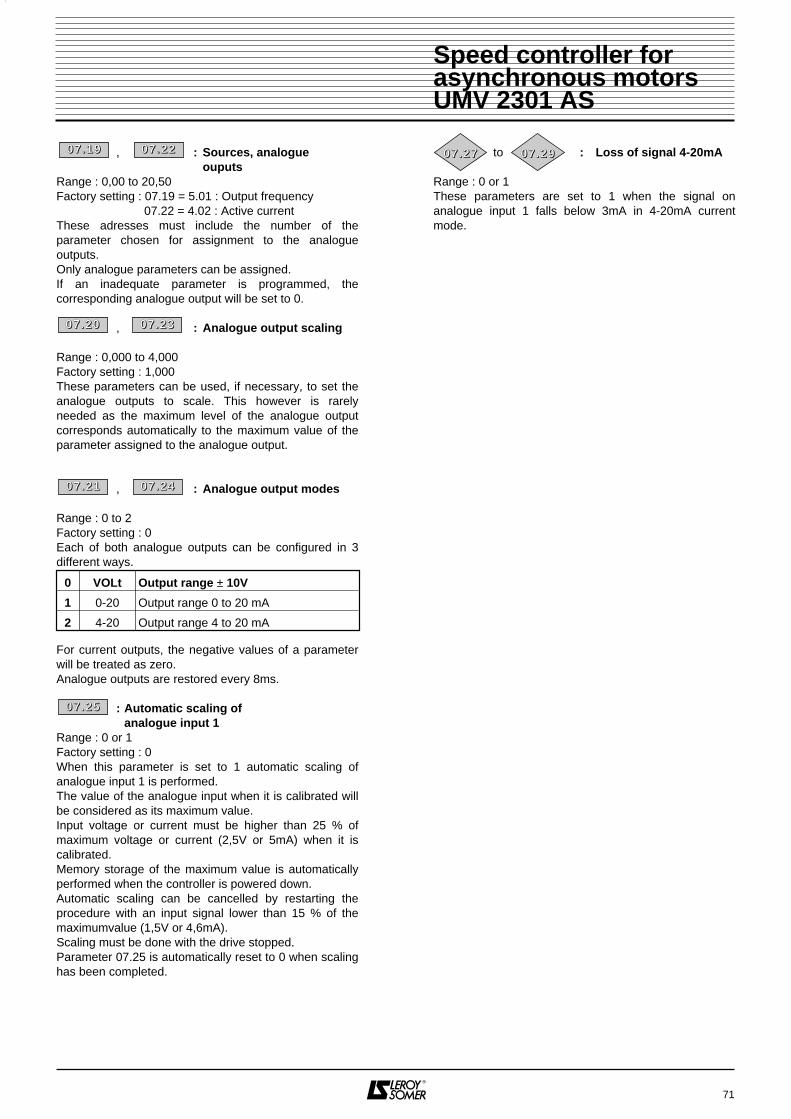
, : Sources, analogue ouputs
Range : 0,00 to 20,50Factory setting : 07.19 = 5.01 : Output frequency
07.22 = 4.02 : Active currentThese adresses must include the number of theparameter chosen for assignment to the analogueoutputs.Only analogue parameters can be assigned.If an inadequate parameter is programmed, thecorresponding analogue output will be set to 0.
, : Analogue output scaling
Range : 0,000 to 4,000Factory setting : 1,000These parameters can be used, if necessary, to set theanalogue outputs to scale. This however is rarelyneeded as the maximum level of the analogue outputcorresponds automatically to the maximum value of theparameter assigned to the analogue output.
, : Analogue output modes
Range : 0 to 2Factory setting : 0Each of both analogue outputs can be configured in 3different ways.
For current outputs, the negative values of a parameterwill be treated as zero.Analogue outputs are restored every 8ms.
: Automatic scaling ofanalogue input 1
Range : 0 or 1Factory setting : 0When this parameter is set to 1 automatic scaling ofanalogue input 1 is performed. The value of the analogue input when it is calibrated willbe considered as its maximum value.Input voltage or current must be higher than 25 % ofmaximum voltage or current (2,5V or 5mA) when it iscalibrated.Memory storage of the maximum value is automaticallyperformed when the controller is powered down.Automatic scaling can be cancelled by restarting theprocedure with an input signal lower than 15 % of themaximumvalue (1,5V or 4,6mA).Scaling must be done with the drive stopped.Parameter 07.25 is automatically reset to 0 when scalinghas been completed.
to : Loss of signal 4-20mA
Range : 0 or 1These parameters are set to 1 when the signal onanalogue input 1 falls below 3mA in 4-20mA currentmode.
71
00 77 .. 22 00 00 77 .. 22 33
00 77 .. 22 11 00 77 .. 22 44
0 VOLt Output range ± 10V
1 0-20 Output range 0 to 20 mA
2 4-20 Output range 4 to 20 mA
00 77 .. 22 55
00 77 .. 22 77 00 77 .. 22 99
Speed controller forasynchronous motorsUMV 2301 AS
00 77 .. 11 99 00 77 .. 22 22

72
Notes
Speed controller forasynchronous motorsUMV 2301 AS

73
4.5.4 - MENU 8 : ASSIGNMENT OF LOGIC INPUTS AND OUTPUTS4.5.4.1 - List over parameters in Menu 8
Parameter Description TypeAdjustment
range UnitFactorysetting
Usersetting
08.01Terminal 24 input or output status indicator
RO 0 or 1 - - -
08.02 Terminal 25 input or output status indicator RO 0 or 1 - - -08.03 Terminal 26 input or output status indicator RO 0 or 1 - - -08.04 Terminal 27 input status indicator RO 0 or 1 - - -08.05 Terminal 28 input status indicator RO - - -08.06 Terminal 29 input status indicator RO - - -08.07 Terminal 30 Enable/Trip input indicator RO - - -08.08 Relay output indicator RO - - -08.09 Select enable input on terminal 30 R-W 0 or 1 - 0
08.10Terminal 24 input destination or output source
R-W 0.00 to 20.50 Menu-parameter 10.06
08.11Terminal 24 logic input / output invert
R-W 0 or 1 - 0
08.12 Configuration of terminal 24 as input or output R-W 0 or 1 - 1
08.13Terminal 25 input destination or output source
R-W 0.00 to 20.50 Menu-parameter 10.33
08.14Terminal 25 logic input / output invert
R-W 0 or 1 - 0
08.15 Configuration of terminal 25 as input or output R-W 0 or 1 - 0
08.16Terminal 26 input destination or output source
R-W 0.00 to 20.50 Menu-parameter 01.45
08.17Terminal 26 logic input / output invert
R-W 0 or 1 - 0
08.18 Configuration of terminal 26 as input or output R-W 0 or 1 - 008.19 Terminal 27 input destination R-W 0.00 to 20.50 Menu-parameter 06.30
08.20Terminal 27 logic input / output invert
R-W 0 or 1 - 0
08.21 Terminal 28 input destination R-W 0.00 to 20.50 Menu-parameter 06.32
08.22Terminal 28 logic input / output invert
R-W 0 or 1 - 0
08.23 Terminal 29 input destination R-W 0.00 to 20.50 Menu-parameter 01.42
08.24Terminal 29 logic input / output invert
R-W 0 or 1 - 0
08.25 Relay output source R-W 0.00 to 20.50 Menu-parameter 10.0108.26 Relay state invert R-W 0 or 1 - 008.27 Logic input polarity R-W 0 or 1 - 008.28 Open collector outputs R-W 0 or 1 - 0
Speed controller forasynchronous motorsUMV 2301 AS

4.5.4.2 - Block diagrams Menu 8Assignment of logic inputs / outputs
74
24
Input 1
1
1
0
1
0
0
0
Output Source
SelectInput/Output
I/O stateterminal 24
I/O stateterminal 25
I/O stateterminal 26
Invertlogic Destination
Analogue input or output F1
Analogue input or output F2
Analogue input or output F3
Read and write
Read only
Read and assign
Symbols
08.01
26
25
08.12
08.27
Logic input polarityPositive
Negative
08.1108.10
Input 1
1
1
0
0
0
Output Source
SelectInput/Output
Invertlogic Destination
Input 1
1
1
0
0
0
Output Source
SelectInput/Output
Invertlogic Destination
08.15
08.1408.13
08.02
08.03
08.18
08.1708.16
Disable +24V side common to logic outputs 08.28
Speed controller forasynchronous motorsUMV 2301 AS

Assignment of logic inputs and relay output
75
27
30
1
1
0
0
Invert logicDestination
Externaltrip
Driveenable
Read and write
Read only
Read and assign
Symbols
28
Select enable /external trip
29
1
0
Invert logicDestination
1
0
Invert logicDestination
08.19
06.29
10.32
08.04
Input stateterminal 27
Input stateterminal 28
Input stateterminal 29
Input stateterminal 30
08.07
2
1Relay output
08.08
08.21
08.09
08.05
08.2308.24
1
0
Invert logic
Output staterelay
08.06
08.20
08.22
Source08.25
08.26
Logic inputF4
Logic inputF5
Logic inputF6
Drive enableinput
Speed controller forasynchronous motorsUMV 2301 AS

4.5.4.3 - Description of pamareters in menu 8
Terminals 24 to 26 can be configured as inputs oroutputs, while terminals 27 to 29 are inputs only. All sixare fully programmable. Furthermore, terminal 30 is adedicated input which can be used either as an enableinput or as external trip input. If both features arerequired then terminal 30 should be used as drive enableinput and one of the other inputs should be programmedto control the external trip bit (an inversion of the inputlogic will be necessary to avoid tripping when inputterminal is active). The logic inputs are sampled and thelogic outputs are updated every 8 ms.
to : Input / Output indicators
(terminals 24 to 26)Range : 0 or 1These parameters indicate the input state of theterminals if these are set up as inputs, or the output stateif they are set up as outputs.For the inputs, 0 = disabled and 1 = enabled.For the outputs, 0 = closed and 1 = open.08.01 = Status of terminal 2408.02 = Status of terminal 2508.03 = Status of terminal 26
to : Input indicators (terminals 27 to 29)
Range : 0 or 1 These parameters indicate the state of these inputs : 0 = disabled and 1 = enabled.08.04 = Status of terminal 2708.05 = Status of terminal 2808.06 = Status of terminal 29
: Enable/Trip input indicator (terminal 30)
Range : 0 or 1 This parameter indicates the state of the Enable/Tripinput (terminal 3) : 0 : disabled.1 : enabled.
: Relay output indicator
Range : 0 or 1 This parameter indicates the state of the drive relay(terminals 1 and 2) : 0 : Relay inactive.1 : Relay active.
: Select enable input (terminal 30)Range : 0 or 1Factory setting : 0Terminal 30 of the controller can be configured either asdrive enable input or as external trip input. 0 : External trip.1 : Enabled
, : Input destination or output source,
, terminals 24 to 26 and relay output
Range : 0.00 to 20.50Factory setting : 08.10 (Terminal 24) : 10.06
(At speed output): 08.13 (Terminal 25) : 10.33
(Trip clearance input): 08.16 (Terminal 26) : 01.45
(Select preset frequency 1/2): 08.25 (Relay output) : 10.01
(Controller not tripping)These parameters are used to select the destination ofthe input if the terminal is set up as an input or thesource of the output if the terminal is set up as an output.Only unprotected " bit " type parameters can be routed toinputs or outputs. If a non valid parameter is addressed to an input or anoutput, no assignment will be taken into account.
: Input destination, terminals 27 to 29
Range : 0.00 to 20.50Factory setting : 08.19 (Terminal 27) : 06.30
(Forward / Stop input): 08.21 (Terminal 28) : 06.32
(Reverse / Stop input): 08.23 (Terminal 29) : 01.42
(Select analogue or preset frequency reference)
These parameters are used to select the destination ofthe logic inputs.Only unprotected " bit " type parameters can be assignedto inputs.If a non valid parameter is programmed, the input will notbe routed anywhere.
, : Invert parameters, logic inputs or outputs
,
,
Range : 0 or 1Factory setting : 0
08.11 - Terminal 24 Allow to invert destination08.14 - Terminal 25 parameter of input or08.17 - Terminal 26 source parameter of output
08.20 - Terminal 27 Allow to invert destination08.22 - Terminal 28 parameter of logic input08.24 - Terminal 29
08.26 - Relay invert : This parameter allows toinvert the relay output
0 : Input or output not inverted.1 : Input or output inverted.
76
00 88 .. 00 11 00 88 .. 00 33
00 88 .. 00 44 00 88 .. 00 66
00 88 .. 00 77
00 88 .. 00 88
00 88 .. 00 99
00 88 .. 11 00 00 88 .. 11 33
00 88 .. 11 66 00 88 .. 22 55
00 88 .. 11 99 00 88 .. 22 11
00 88 .. 22 33
00 88 .. 11 11 00 88 .. 11 44
00 88 .. 11 77 00 88 .. 22 00
00 88 .. 22 22 00 88 .. 22 44
00 88 .. 22 66
Speed controller forasynchronous motorsUMV 2301 AS

: Activate outputparameters(terminals 24 to 26)
Range : 0 or 1Factory setting : 08.12 (Terminal 24) : 1 (Output)
: 08.15 (Terminal 25) : 0 (Input) : 08.18 (Terminal 26) : 0 (Input)
These parameters allow to set up terminals 24 to 26 asinput or output.0 : Configuration of terminal as Input.1 : Configuration of terminal as Output.
: Logic input polarity Range : 0 or 1Factory setting : 0This parameter allows to choose a positive or negativelogic polarity on digital inputs.0 : Negative logic, input is enabled when the terminalis driven at a low level (< 5V).1 : Positive logic, input is enabled when the terminal isdriven at a high level (> 15V).
: Open collector outputsRange : 0 or 1Factory setting : 0Allows to disable the +24V high side of the logic circuits.Thus several controllers can be connected together in awired "OR" configuration. 0 : +24V enabled.1 : +24V disabled.
77
00 88 .. 11 22 00 88 .. 11 55
00 88 .. 11 88
00 88 .. 22 77
00 88 .. 22 88
Speed controller forasynchronous motorsUMV 2301 AS

78
Notes
Speed controller forasynchronous motorsUMV 2301 AS

79
4.5.5 - MENU 9 : LOGIC FUNCTIONS AND FASTER / SLOWER COMMAND4.5.5.1 - List over parameters in Menu 9
Parameter Description Type Adjustmentrange Unit Factory
settingUser
setting
09.01Output indicator of logic function 1 & 2 RO 0 or 1 - - -
09.02Output indicator of logic function 3 & 4 RO 0 or 1 - - -
09.03 Motorized pot output RO ± 100,0 % - -09.04 Source of input 1 of function 1 & 2 R-W 0.00 to 20.50 Menu-parameter 009.05 Invert input 1 of function 1 & 2 R-W 0 or 1 - 009.06 Source of input 2 of function 1 & 2 R-W 0.00 to 20.50 Menu-parameter 009.07 Invert input 2 of function 1 & 2 R-W 0 or 1 - 009.08 Invert output of function 1 & 2 R-W 0 or 1 - 009.09 Delay function 1 & 2 R-W 0,0 to 25,0 s09.10 Destination of output of function 1 & 2 R-W 0.00 to 20.50 Menu-parameter 009.11 Not used -09.12 Not used -09.13 Not used -09.14 Source of input 3 of function 3 & 4 R-W 0.00 to 20.50 Menu-parameter 009.15 Invert input 3 of function 3 & 4 R-W 0 or 1 - 009.16 Source of input 4 of function 3 & 4 R-W 0.00 to 20.50 Menu-parameter 009.17 Invert input 4 of function 3 & 4 R-W 0 or 1 - 009.18 Invert output of function 3 & 4 R-W 0 or 1 - 009.19 Delay function 3 & 4 R-W 0,0 to 25,0 s09.20 Destination of output of function 3 & 4 R-W 0.00 to 20.50 Menu-parameter 0
09.21Select automatic reset of faster / slower commandreference R-W 0 or 1 - 0
09.22 Select polarity of faster / slower reference R-W 0 or 1 - 0
09.23Ramp rate of faster / slower commandreference R-W 0 to 250 s 20
09.24Scaling of faster / slower commandreference R-W 0,000 to 4,000 Factor 1,000
09.25Destination of faster / slower commandreference R-W 0.00 to 20.50 Menu-parameter 0
09.26 Input faster R-W - - - -09.27 Input slower R-A - - - -
09.28Reset of faster / slower commandreference R-A 0 or 1 - -
09.29 Binary input 1 of binary / decimal converter R-A - - - -09.30 Binary input 2 of binary / decimal converter R-A - - - -09.31 Binary input 3 of binary / decimal converter R-A - - - -09.32 Read decimal output RO 0 to 7 - - -09.33 Destination of decimal output R-W 0.00 to 20.50 Menu-parameter 0
Speed controller forasynchronous motorsUMV 2301 AS

4.5.5.2 - Block diagrams Menu 9Logic functions
80
&
Statelogic function
1 & 2
Destination
Statelogic function
3 & 4
Destination
Read and write
Read only
Read and assign
Symbols
09.04
09.05
09.08
09.10
Source 1
Source 2
State 1
State 2
Invert logic
&
Invert logic
Invert logic
09.09
Delay
09.14
09.15
09.17
09.18
09.20
09.16
Source 3
Source 4
State 3
State 4
Invert logic
Invert logic
Invert logic
09.19Delay
Logic function 3 & 4
Logic function 1 & 2
09.01
09.02
09.07
09.06
1
0
1
0
1
0
1
0
1
0
1
0
Speed controller forasynchronous motorsUMV 2301 AS

81
Speed controller forasynchronous motorsUMV 2301 AS
Binary / Decimal converter
Faster / Slower function
Faster
Slower
ScalingReference
%
Destination
Select resetat
power up
Reset to zeroreference
%+100
0
%+100
–100
0
t
Selectpolarities
Ramp
Read and write
Read only
Read and assign
Symbols
00001111
00110011
01010101
01234567
09.21
09.25
Destination09.33
09.26
09.27
09.31
09.30
09.29
09.24
09.28
09.32
09.03
09.22
09.23
Readdecimal output
Combinationof binary inputs

4.5.5.3 - Description of parameters in menu 9
, : Logic function output indicators
Range : 0 or 1These parameters indicate the output state of the twoprogrammable logic functions. This output can be routedto a terminal by setting the appropriate digital outputsource in Menu 8 to output one of these parameters.09.01 : Logic function 1 output09.02 : Logic function 2 output
: Read reference coming from Faster / Slower command
Range : ± 100,0Unit : %Level of the reference given by the motorizedpotentiometer prior to scaling.
, : "AND" functionsinputs sources
,Range : 0.00 to 20.50Factory setting : 09.04 (Source 1 function 1 & 2) : 0
: 09.06 (Source 2 function 1 & 2) : 0: 09.14 (Source 3 function 3 & 4) : 0: 09.16 (Source 4 function 3 & 4) : 0
These parameters are used to select the sources of theinputs of the "AND" logic functions.Only " bit " type parameters can be processed on theseinput.If 2 inadequate parameters are addressed on both inputsof an "AND" function, the output of the "AND" functionwill remain at 0.If only 1 inadequate parameter is addressed on 1 of bothinputs of an "AND" function, this input will be set at 1.
, : Logic inversion of "AND" functions inputs
,Range : 0 or 1Factory setting : 09.05 (Inversion of input 1 of
function 1 & 2) : 0: 09.07 (Inversion of input 2 of
function 1 & 2) : 0: 09.15 (Inversion of input 3 of
function 3 & 4) : 0: 09.17 (Inversion of input 4 of
function 3 & 4) : 0These parameters are used to make a logic inversion onthe inputs of the "AND" functions.0 : Input not inverted.1 : Input inverted
, : Logic inversion of "AND" functions outputs
Range : 0 or 1Factory setting : 09.08 (Inversion of output of
function 1 & 2) : 0: 09.18 (Inversion of output of
function 3 & 4) : 0These parameters are used to make a logic inversion onthe outputs of the "AND" functions.0 : Output not inverted.1 : Output inverted
, : Time delay of "AND" functions outputs
Range : 0,0 to 25,0sFactory setting : 09.09 (Time delay of the output of
function 1 & 2) : 0: 09.19 (Time delay of the output of
function 3 & 4) : 0These parameters are used to introduce a time delay onthe outputs of the "AND" functions.This time delay is only active when the output switchesfrom 0 to 1 (Operational time delay).
, : Destination of "AND" functions outputs
Range : 0.00 to 20.50Factory setting : 09.10 (Destination of the output of
function 1 & 2) : 0: 09.20 (Destination of the output of
function 3 & 4) : 0These parameters define which internal parameters willbe assigned by the outputs of the "AND" functions.Only unprotected " bit " type parameters can be ad-dressed.If an inadequate parameter is programmed, thedestination will not be taken into account.
: Select automatic reference reset for Faster / Slower command
Range : 0 or 1 Factory setting : 00 : Reference of Faster / Slower command willremain at the same level on power-up as it was onpower-down.1 : Reference of Faster / Slower command will be resetat zero each time the controller is powered up.
: Select polarity of Faster / Slower reference
Range : 0 or 1Factory setting : 00 : Reference of Faster / Slower command is limitedto positive values (0 to 100,0 %).1 : Reference of Faster / Slower command could varybetween -100 % and +100 %.
82
00 99 .. 00 11 00 99 .. 00 22
00 99 .. 00 33
00 99 .. 00 44 00 99 .. 00 66
00 99 .. 11 44 00 99 .. 11 66
00 99 .. 00 55 00 99 .. 00 77
00 99 .. 11 55 00 99 .. 11 77
00 99 .. 00 88
00 99 .. 00 99 00 99 .. 11 99
00 99 .. 11 00 00 99 .. 22 00
00 99 .. 22 11
00 99 .. 22 22
Speed controller forasynchronous motorsUMV 2301 AS
00 99 .. 11 88

: Ramp rate of reference ofFaster / Slower command
Range : 0 to 250sFactory setting : 20This parameter sets the time which is necessary for thereference of the Faster / Slower command to vary from 0to 100,0 %.Twice as much time will be needed for the reference tovary from -100,0 % to +100,0 %.This parameter sets the sensitivity of the command.
: Scaling of reference ofFaster / Slower command
Range : 0,000 to 4,000Factory setting : 1,000The maximum value of the reference of the Faster /Slower command automatically takes the maximumvalue of the analogue reference it is assigned to.This parameter thus allows to adapt the maximum valueof the reference of the Faster / Slower command to themaximum value required for the application.
Example : - The reference of the Faster / Slower command is addressed to a preset speed.- The maximum value of a preset speed is 1000 Hz.- It is requested that the maximum value of the Faster / Slower reference corresponds to 50 Hz.==> 09.24 = = 0,05.
: Destination of reference ofFaster / Slower command
Range : 0.00 to 20.50Factory setting : 0This parameter is used to define which analogueparameter will be controlled by the reference of theFaster / Slower command.
• Example 1 : The reference of the Faster/Slower command is used as speed reference. It is possible to send the reference of the Faster/ Slower command to a preset speed.==> 09.25 = 01.21.• Example 2 :The reference of the Faster/Slower command is used to adjust speed of a machine. It is possible to send the reference of the Faster / Slower command to the speed reference offset.==> 09.25 = 01.04.
& : Inputs Faster, SlowerTwo logic inputs must be assigned to these parametersof the command of Faster / Slower function.09.26 : Input Faster.09.27 : Input Slower.
: Manual reset of reference ofFaster / Slower command
Range : 0 or 1Factory setting : 0When this parameter is set at 1, the reference of theFaster / Slower command is reset at zero.
, : Binary inputs of the binary / decimal converter
• Assign 1 logic input to obtain a decimal conversion 0 or1.• Assign 2 logic inputs to obtain a decimal conversion 0to 3.• Assign 2 logic inputs to obtain a decimal conversion 0to 7.09.29 : Input binary sum 1.09.30 : Input binary sum 2.09.31 : Input binary sum 4.Allows remote modification of a parameter whichselection includes more than 2 possible choices thanksto a combination of logic inputs.
: Read decimal output
Range : 0 to 7Allows to read the value of the binary converter output.
: Destination of decimal outputRange : 0.00 to 20.50Factory setting : 0This parameter is used to define which parameter will becontrolled by the decimal output.Example : 04.11 - Torque control features 5 operatingmodes (0 to 4).
83
00 99 .. 22 33
00 99 .. 22 44
501000
00 99 .. 22 55
00 99 .. 22 66 00 99 .. 22 77
00 99 .. 22 99
00 99 .. 33 33
00 99 .. 33 00
00 99 .. 33 11
00 99 .. 33 22
Speed controller forasynchronous motorsUMV 2301 AS
00 99 .. 22 88

84
Notes
Speed controller forasynchronous motorsUMV 2301 AS

85
4.5.6 - MENU 10 : STATUS OF CONTROLLER AND DIAGNOSIS4.5.6.1 - List over parameters in Menu 10
Speed controller forasynchronous motorsUMV 2301 AS
Parameter Description TypeAdjustment
range UnitFactorysetting
Usersetting
10.01 Controller ready RO 0 or 1 - - -10.02 Enable controller output RO 0 or 1 - - -10.03 Zero speed RO 0 or 1 - - -10.04 Minimum speed RO 0 or 1 - - -10.05 Not used - - - - -10.06 At speed RO 0 or 1 - - -10.07 Not used - - - - -10.08 Rated load RO 0 or 1 - - -10.09 Enable current limitation RO 0 or 1 - - -10.10 Dynamic braking RO 0 or 1 - - -10.11 Resistor braking RO 0 or 1 - - -10.12 Alarm overload braking resistor RO 0 or 1 - - -10.13 Reverse rotation requested RO 0 or 1 - - -10.14 Reverse rotation RO 0 or 1 - - -10.15 No mains RO 0 or 1 - - -10.16 Fault motor overheating RO 0 or 1 - - -10.17 Alarm It overheating RO 0 or 1 - - -10.18 Alarm controller overheating RO 0 or 1 - - -10.19 Alare ambient temperature RO 0 or 1 - - -10.20 Fault - 1 RO 0 to 99 Code - -10.21 Fault - 2 RO 0 to 99 Code - -10.22 Fault - 3 RO 0 to 99 Code - -10.23 Fault - 4 RO 0 to 99 Code - -10.24 Fault - 5 RO 0 to 99 Code - -10.25 Fault - 6 RO 0 to 99 Code - -10.26 Fault - 7 RO 0 to 99 Code - -10.27 Fault - 8 RO 0 to 99 Code - -10.28 Fault - 9 RO 0 to 99 Code - -10.29 Fault - 10 RO 0 to 99 Code - -10.30 Maximum resistor braking time R-W 0 to 400s s 010.31 Maximum resistor braking cycle time R-W 0,0 to 25,0 mn 010.32 External fault RO 0 or 1 - - -10.33 Fault clearance R-W 0 or 1 010.34 Number of automatic fault clearances R-W 0 to 5 Number 010.35 Time delay of automatic fault clearance R-W 0 - 25,0s s 1,0
10.36Controller operational status maintained duringautomatic fault clearances R-W 0 or 1 - 0
10.37 Minor faults R-W 0 or 1 - 010.38 Assignable forced fault R-W 0 to 100 Code 010.39 Integration of overload braking resistor RO 0,0 to 100,0 % - -10.40 Decimal value of binary status from 10.01 to 10.15 RO 0 to 32767 - - -

4.5.6.2 - Block diagrams Menu 10
86
Speed controller forasynchronous motorsUMV 2301 AS
10.01
10.02
10.03
10.04
Drive ready
Drive running
Zero speed
Minimum speed
Not used
Atspeed
Not used
Rated load
Active current limit
Dynamic braking
Resistor braking
Overload alarm, braking resistor
Reverse rotation commanded
Reverse rotation
Mains loss
Motor overheating
10.05
10.06
10.07
10.08
10.09
10.10
10.11
10.12
10.13
10.14
10.15
10.16
10.17
10.18
10.19
10.20
It overload alarm
Heat sink temperature alarm
Ambient temperature alarm
Trip - 1
Trip - 2
Trip - 3
Trip - 4
Trip - 5
Trip - 6
Trip - 7
Trip - 8
Trip - 9
Trip - 10
External trip
Status word, parameters10.01 to 10.15
10.21
10.22
10.23
10.24
10.25
10.26
10.27
10.28
10.29
10.32
10.40
Status and trips

Block diagrams Menu 10 (contd)
87
10.30
10.31
10.39
Full power braking time
Full power braking period
Braking energy overload accumulator
Resistor braking
10.33
10.34
Drive reset
Number of auto reset attempts
Auto reset delay
Hold "Drive ready" until last attempt
Stop drive on minor trips
Fault processing
10.35
10.36
10.37
Speed controller forasynchronous motorsUMV 2301 AS

4.5.6.3 - Explication des paramètres du menu 10
: Controller status operational
Range : 0 or 1This parameter is set at 1 as long as the controller hasnot tripped. If parameter 10.36 is set at 1, this bit willremain at 1 during fault phase if an automatic faultclearance is to occur. Once the number of automaticclearances is reached, next fault will set this bit at zero.
: Controller running
Range : 0 or 1 This parameter is set at 1 when the controller output isenabled.
: Zero speed
Range : 0 or 1 This parameter is set at 1 when the absolute value oframp output is ≤ 1Hz.
: Operation at speed below or equal to minimum threshold
Range : 0 or 1 In bipolar mode (01.10 = 1) this parameter has the samefunction as zero speed parameter (10.03).In unipolar mode this parameter is set at 1 the absolutevalue of ramp output is ≤ minimum frequency + 0,5 Hz.Minimum speed is set with parameter 01.07.The parameter is operational only when the controller isrunning.
: Not used
: At speed
Range : 0 or 1 This parameter is set at 1 when the absolute value oframp output is equal to set speed (1.03) ± 1Hz.The parameter is operational only when the controller isrunning.
: Not used
: At rated active current
Range : 0 or 1 This parameter is set at 1 when the active current is ≥rated active current.Rated active current = 00.46 x 00.43.
: Enable current limitation
Range : 0 or 1 This parameter is set at 1 when the controller isoperating with current limitation.
: Generator mode
Range : 0 or 1 This parameter is set at 1 when energy is transferredfrom the motor to the DC bus (driving load).
: Enable dynamic braking
Range : 0 or 1 This parameter is set at 1 when energy is dissipated inthe optional braking resistor (provided it is connected).
: Alarm dynamic braking
Range : 0 or 1 This parameter is set at 1 if dynamic braking is enabledand cumulated braking energy is exceeding 75 %.
: Indication of requested rotation direction
Range : 0 or 1 This parameter is set at 1 if reference before ramp isnegative (reverse).It is reset at zero if reference before ramp is positive(forward).
: Indication of rotation direction when running
Range : 0 or 1 This parameter is set at 1 if reference after ramp isnegative (reverse).It is reset at zero if reference before after is positive(forward).
: Loss of mains
Range : 0 or 1 This parameter is set at 1 when controller input voltageis under 380V -10 %.
: Motor overheating
Range : 0 or 1 This parameter is set at 1 when motor probe reaches alevel over tripping threshold.
: Alarm overload
Range : 0 or 1 This parameter is set at 1 when motor current isexceeding 105 % of programmed rated motor currentand cumulated overload is exceeding 75 % of motoroverload capacity. If motor current is not reduced, thecontroller will trip on I x t.
88
Speed controller forasynchronous motorsUMV 2301 AS
11 00 .. 00 11
11 00 .. 00 22
11 00 .. 00 33
11 00 .. 00 44
11 00 .. 00 55
11 00 .. 00 66
11 00 .. 00 77
11 00 .. 00 88
11 00 .. 00 99
11 00 .. 11 00
11 00 .. 11 11
11 00 .. 11 22
11 00 .. 11 33
11 00 .. 11 44
11 00 .. 11 55
11 00 .. 11 66
11 00 .. 11 77

: Alarm heat sink temperature
Range : 0 or 1 This parameter is set at 1 when heat sink temperature isexceeding 95°C and the controller is still overloaded.
: Alarm ambient temperature
Range : 0 or 1 This parameter is set at 1 when ambient temperature isexceeding 65°C.
to : Memorization of 10 last faults
Range : 0 to 99These parameter register the 10 last faults of thecontroller. Possible faults are :
10.20 indicates the most recent fault.10.29 indicates the most ancient fault.
: Maximum full power braking period
Range : 0,0 to 400,0sFactory setting : 0sThis parameter defines the time during which the brakingresistor is able to withstand maximum braking voltage(780V) without damage. It allows to set the time beforetripping on braking overload.
: Interval between full power braking periods
Range : 0,0 to 25,0mnFactory setting : 0mnThis parameter defines the time interval which mustelapse between two consecutives full power brakingperiods as described with parameter 10.30. It is used toset the thermal time factor of the resistance. If thisparameter is left at 0 then there will be no protection onthe braking resistor.
: External fault
Range : 0 or 1This parameter is set at 1 when the " External fault" inputis at 0.If parameter 08.09 is set at 0, then " External fault" inputcorresponds to terminal 30.If terminal 30 is used as " locking" input (08.09 = 1), it ispossible to use another terminal as external fault inputby inversing the signal to avoid tripping when the input isat 1.
89
Speed controller forasynchronous motorsUMV 2301 AS
N°Mnemonic
Display Fault
1 UU DC bus undervoltage2 OU DC bus overvoltage3 OI. AC Overcurrent controller output4 OI. br Overcurrent braking resistor5 PS Fault internal power supply6 Et Forced external fault7 OV. Spd Overspeed19 it. br Overload braking resistor20 it. AC Overload motor I x t
21 Oh 1Thermal heat sink simulation functionof I x t
22 Oh 2Overheating heat sink detected bytemperature probe (over 90°C)
23 OA Overheating control board
24 th Trip on motor temperature probe
25 thS
Short-circuit on motor temperatureprobe CTP (terminal 8) with THSconfigurated input
26 OP.OVLd Overload on + 24V or logic outputs
27 CL1
Loss of current setting on analogueinput 1 with parameter 07.06 set at(4-20tr or 20-4tr)
28 CL2
Loss of current setting on analogueinput 2 with parameter 07.11 set at(4-20tr or 20-4tr)
29 CL3
Loss of current setting on analogueinput 3 with parameter 07.15 set at(4-20tr or 20-4tr)
30 SCL Loss of serial link communication31 EEF EEPROM fault32 Ph Loss of power supply phase
33 rsFault during measurement of statoric resistance
40to49
tr xx
Specific user faults related to seriallink
11 00 .. 33 00
11 00 .. 33 11
Temperature
Max
Ambient10.30
10.31
11 00 .. 11 88
11 00 .. 11 99
11 00 .. 22 00 11 00 .. 22 99
11 00 .. 33 22

: Reset controllerRange : 0 or 1Factory setting : 0Switching from 0 to 1 of this parameter commands areset of the controller.If a remote fault clearance is necessary, a terminal mustbe assigned to this parameter.If the controller trips on an IGBT overcurrent, either onthe output bridge or the braking transistor, the controllercannot be reset at zero during 10 seconds (IGBTregeneration time).
: Number of automatic faultclearances
Range : 0 to 5Factory setting : 00 : No automatic fault clearance. It should becommanded.1 à 5 : Involve as many automatic fault clearances as theprogrammed number.When the counter reaches the authorized number of automatic fault clearances, the controller is definitelylocked. Clearance of this last fault must necessarily becommanded. The counter is reset at zero when the fault which occursis not similar to the previous one or when there is nofault during 5 minutes.Automatic fault clearance is impossible on external fault(Et).
: Time delay of automatic faultclearance
Range : 0,0 to 25,0sFactory setting : 1,0sThis parameter sets the time which must elapse betweencontroller tripping and automatic clearance (providedminimum stop time for faults related to overcurrents isrespected).
: Operational status maintained until definitive tripping
Range : 0 or 1Factory setting : 00 : Parameter 10.01 (Controller status operational) isreset at zero each time the controller is tripping,without consideration for automatic fault clearancesthat might occur.1 : Parameter 10.01 is kept at 1 during the trip phaseswhich are automatically cleared
: Control of deceleration on minor faults
Range : 0 or 1Factory setting : 01 : The controller will adjust deceleration before trippingon minor faults.Minor faults are those which codes are between 16 and26 inclusive.0 : The controller trips instantaneously on minorfaults. Deceleration is then obtained throughcoasting.
: Tripping on user faultsRange : 0 to 100Factory setting : 0This parameter is used to induce tripping on user faults,transmitted through the serial link.Valid fault codes are 27 to 99, any value lower than 27will refer to an already existing fault.Trips released by the user will be displayed as trxx in thefault table, xx being the fault code.User wishing to reset the controller at zero via the seriallink can do it by setting this parameter at 100.
: Temperature image of braking resistor
Range : 0,0 to 100,0 %This parameter gives an indication of the braking resistortemperature according to the model described before. Azero value means that the resistor is close to theambient temperature and 100 % is maximumtemperature (tripping level).
: Read status
Range : 0 to 32767This parameter is used together with a serialcommunication interface. The value of this parameter isthe sum of the controller bits planned for read only, withthe following binary weights : - 10.01 = 20,- 10.02 = 21,- 10.03 = 22,- 10.04 = 23,- 10.05 = 24,- 10.06 = 25,- 10.07 = 26,- 10.08 = 27,- 10.09 = 28,- 10.10 = 29,- 10.11 = 210,- 10.12 = 211,- 10.13 = 212,- 10.14 = 213,- 10.15 = 214.
90
Speed controller forasynchronous motorsUMV 2301 AS
11 00 .. 33 33 11 00 .. 33 88
11 00 .. 33 44
11 00 .. 33 55
11 00 .. 33 66
11 00 .. 33 77
11 00 .. 33 99
11 00 .. 44 00

91
4.5.7 - MENU 12 : PROGRAMMABLE THRESHOLDS4.5.7.1 - List over parameters in Menu 12
Parameter Description TypeAdjustment
range UnitFactorysetting
Usersetting
12.01 Threshold comparator 1 output RO 0 or 1 - - -12.02 Threshold comparator 2 output RO 0 or 1 - - -12.03 Threshold source comparator 1 R-W 0,00 to 20,50 Menu-parameter 012.04 Threshold level comparator 1 R-W 0,0 to 100,0 % 012.05 Threshold hysteresis comparator 1 R-W 0,0 to 25,0 % 012.06 Output invert flag comparator 1 R-W 0 or 1 012.07 Threshold destination comparator 1 R-W 0,00 to 20,50 Menu-parameter 012.08 Not used -12.09 Not used -12.10 Not used -12.11 Not used -12.12 Not used -12.13 Threshold source comparator 2 R-W 0,00 to 20,50 Menu-parameter 012.14 Threshold level comparator 2 R-W 0,0 to 100,0 % 012.15 Threshold hysteresis comparator 2 R-W 0,0 to 25,0 % 012.16 Output invert flag comparator 2 R-W 0 or 1 012.17 Threshold destination comparator 2 R-W 0,00 to 20,50 Menu-parameter 0
Speed controller forasynchronous motorsUMV 2301 AS

4.5.7.2 - Block diagrams Menu 12
92
Threshold 1
0
1
Threshold 2
Read and write
Read only
Read and assign
Symbols
12.0512.03
12.06
12.07
Source
Thresholdlevel
12.01
Hysteresis
Thresholdexceeded
Invertlogic
Destination
12.04
0
1
12.1512.13
12.16
12.17
Source
Thresholdlevel
12.02
Hysteresis
Thresholdexceeded
Invertlogic
Destination
12.14
Speed controller forasynchronous motorsUMV 2301 AS

4.5.7.3 - Description of parameters in menu 12
& : Threshold comparatoroutputs
Range : 0 or 1These parameters indicate wether the input variables areabove (1) or below (0) the programmed thresholds.12.01 : Output comparator 1.12.02 : Output comparator 2.
& : Threshold sourcesRange : 0,00 to 20,50Factory setting : 0These parameters define which variable should becompared to the programmed thresholds.The absolute value of the source variable is taken asinput to the threshold comparator. Only non-bitparameters can be programmed as a source.If a non valid parameter is programmed, the consideredinput value will be 0.12.03 : Source comparator 1.12.13 : Source comparator 2.
& : Threshold levelsRange : 0,0 to 100,0 %Factory setting : 0 %These parameters are used for setting the switchingthresholds of the comparators.The thresholds are expressed as a percentage of thesource maximum values.12.04 : Threshold comparator 1.12.14 : Threshold comparator 2.
& : Threshold hysteresis Range : 0,0 to 25,0 %Factory setting : 0 %These parameters define the band inside of which thecomparator output will not switch. The output will get to 1 when the variable reachesthreshold value + (hysteresis 2).The output will get to 0 when the variable value passesbelow threshold value + (hysteresis 2).Hysteresis is expressed as a percentage of the sourcemaximumvalue.
& : Output invert flags Range : 0 or 1Factory setting : 0These parameters are used to invert the thresholdoutputs of the comparators.0 : Output not inverted.1 : Output inverted.12.06 : Output comparator 1 inverted.12.16 : Output comparator 2 inverted.
& : Threshold destination
Range : 0,00 to 20,50Factory setting : 0These parameters define the destination of the twoprogrammable thresholds. Only bit-type parameters can be programmed asthreshold outputs.If a non valid parameter is programmed, the output is notrouted anywhere.
93
11 22 .. 00 33 11 22 .. 11 33
11 22 .. 00 11 11 22 .. 00 22
11 22 .. 00 44 11 22 .. 11 44
11 22 .. 00 55 11 22 .. 11 55
••
••
11 22 .. 00 66 11 22 .. 11 66
11 22 .. 00 77 11 22 .. 11 77
Speed controller forasynchronous motorsUMV 2301 AS

94
Notes
Speed controller forasynchronous motorsUMV 2301 AS

95
4.5.8 - MENU 14 : PID CONTROL4.5.8.1 - List over parameters in Menu 14
Parameter Description TypeAdjustment
range UnitFactorysetting
Usersetting
14.01 PID output RO ±100 % - -14.02 Source parameter of PID output R-W 0,00 to 20,50 Menu-parameter 014.03 PID reference input source R-W 0,00 to 20,50 Menu-parameter 014.04 PID feedback input source R-W 0,00 to 20,50 Menu-parameter 014.05 PID reference invert R-W 0 or 1 - 014.06 PID feedback invert R-W 0 or 1 - 014.07 PID reference slew rate limit R-W 0 à 3200,0 s 014.08 PID enable R-W 0 or 1 - 014.09 Optional PID enable source R-W 0,00 to 20,50 Menu-parameter 014.10 PID proportional gain R-W 0 to 4,000 Factor 1,00014.11 PID integral gain R-W 0 to 4,000 Factor 0,50014.12 PID derivative gain R-W 0 to 4,000 Factor 0,00014.13 PID high limit R-W 0 to 100,0 % 100,014.14 PID low limit R-W ± 100,0 % -100,014.15 PID scale factor R-W 0,000 to 4,000 Factor 1,00014.16 PID output destination R-W 0,00 to 20,50 Menu-parameter 014.17 Hold integrator R-W 0 or 1 - 0
Speed controller forasynchronous motorsUMV 2301 AS

4.5.8.2 - Block diagrams Menu 14
96
Mainreference source
PID reference source
PID feedback source
1
0
Invert polarity
PID slew rate
PID output
Drive enable
Invert polarity
PID enable
&
Error
Enable
Scaling%
Hold integratorDestination
Read and write
Read only
Read and assign
Symbols
14.01
14.16
14.15X
14.02
14.03 14.17
X-1
High limit
Low limit
10.01
14.07
14.05
1
0
X-1
14.13
14.14
P 14.10
I 14.11
D 14.12
14.06
14.04
Optional PID enable source
14.09 14.08
Speed controller forasynchronous motorsUMV 2301 AS

4.5.8.3 - Description of parameters in menu 14
: PID output
Range : ± 100 %This parameter monitors the output level of the PIDcontroller prior to scaling.
to : PID input sourcesRange : 0,00 to 20,50Factory setting : 0These parameters define which variables will serve asinputs to the PID controller.Only non-bit parameters can be programmed assources. If a non valid parameter is programmed theconsidered input value will be 0.All PID variables will automatically be set to scale sothey have a variation range of ± 100,0 % or 0 - 100,0 %if they are unipolar.14.02 : Source parameter added to PID output in the
destination.14.03 : PID reference input.14.04 : PID feedback input.
& : Input invert bitsRange : 0 or 1Factory setting : 0These parameters are used to invert the sign of the PIDreference and PID feedback.0 : Input not inverted.1 : Input inverted.14.05 : PID reference invert.14.06 : PID feedback invert.
: PID reference slew rate limitRange : 0 to 3200,0 sFactory setting : 0 sThis parameter sets the time necessary for the PIDreference to ramp from 0 to 100,0 % after a sudden 0 to100 % step change in input. Changes from -100,0 % to+100,0 % will require twice this time.
: PID enableRange : 0 or 1Factory setting : 0This parameter must be set to 1 for the PID controller tooperate.If this parameter is set to 0, PIDoutput will be 0.
: Optional PID enable source Range : 0,00 to 20,50Factory setting : 0This parameter allows to enable the PID controller withan additional condition to 14.08.To enable the PID controller, 14.08, 10.01 as well as thisoptional condition must be set to 1.Only bit parameters can be programmed.If a non valid parameter is programmed the input willautomatically be 1 to prevent locking of the enableoutput.
: PID proportional gainRange : 0 to 4,000Factory setting : 1,000It is the proportionnal gain applied to the PID error.
: PID integral gainRange : 0 to 4,000Factory setting : 0,500It is the gain applied to the PID error before beingintegrated.
: PID derivative gainRange : 0 to 4,000Factory setting : 0,000It is the gain applied to the PID error before beingdifferentiated.
: PID high limit Range : 0 to 100,0 %Factory setting : 100,0 %This parameter allows to limit the maximum positivevalue of the PID output.
: PID low limit Range : ± 100,0 %Factory setting : -100,0 %This parameter allows to limit the maximum negativevalue or the minimum positive value of the PID output.
: PID scale factorRange : 0,000 to 4,000Factory setting : 1,000This parameter allows to set the PID output to scalebefore being added to the main reference.After addition, the output will automatically be scaledagain to match the variation range of the destinationparameter.
: PID output destinationRange : 0,00 to 20,50Factory setting : 0This parameter allows to define to which parameter thePID output is addressed. Only unprotected non-bit parameters can be controlled.If a non valid parameter is programmed the output is notrouted anywhere. If the PID is to control speed, then it is recommended toenter one of the preset speed parameters here.If the PID is to trim speed, then it is recommended toenter the offset parameter (01.04) here.
: Hold integratorRange : 0 or 1Factory setting : 00 : Integrator is reset to 0 each time the PID loop isdisabled.1 : The integrator value is held each time the PID loop isdisabled.
97
11 44 .. 00 55
11 44 .. 00 11
11 44 .. 00 66
11 44 .. 00 22 11 44 .. 00 44
11 44 .. 00 77
11 44 .. 00 99
11 44 .. 11 00
11 44 .. 00 88
11 44 .. 11 11
11 44 .. 11 22
11 44 .. 11 44
11 44 .. 11 33
11 44 .. 11 55
11 44 .. 11 66
11 44 .. 11 77
Speed controller forasynchronous motorsUMV 2301 AS

98
N°Mnemonic
displayTrip
cause Check points Solution
1 UU DC bus undervoltage • Power supply terminals L1, L2,L3 / mains undervoltage
• Check mains power supply• Check power components
2 OU DC bus overvoltage • Deceleration too fast (inertial load)
• Terminals L1, L2, L3 / mains un-dervoltage
• Program longer deceleration time in 00.04
• Check deceleration mode in 00.15• Fit a braking resistor (optional)• Check mains power supply
3 OI. AC Overcurrent atcontroller output
• Power terminal blocks U, V, W• Wiring
• Eliminate short-circuit at controller output
• Program longer acceleration time in 00.03
4 OI. br Overcurrentbraking resistor
• Power terminal blocks +, •, –• Braking resistor, value
• Eliminate short-circuit at resistor output• Increase resistor ohmic value
5 PS Internal power supplyfaulty
• Terminals + 10V and + 24V • Check that load on + 10V and + 24V is compatible with maximum flow
• Eliminate short-circuit on + 10V or + 24V terminal
6 Et Forced external fault • Terminal 30 in open loop mode • Check that terminal 30 is connected to 0 V byexternal wiring (negative logic)
7 OV. Spd Overspeed • Motor speed higher than setspeed
• Check that the load is not driving• Adjust speed loop gains
19 it. br Overload brakingresistor
• Braking resistor• Braking resistor wiring• Integrated braking resistor• Braking cycle
too important
• Increase ohmic value• Check wiring• Check braking transistor• Increase braking cycle
20 it. AC Motor overload I x t • Motor load• Adjustment of IN motor
• Check that motor is not overloaded• Check that motor rated current is
correctly set (00.46)21 Oh 1 Thermal simulation of
heat sink dependingonI x t
• Adjustment of IN motor • Reduce motor load• Reduce cycle
22 Oh 2 Heat sink overheating detected by thermalprobe (over 90°C)
• cooling ventilator (if fited)
• Ambient temperature
• Check that :- ventilators are spinning- cooling louvres are not obstructed
23 OA Control cardoverheating
- temperature is lower than 50°C- there is enough clearance around controller
24 th Motor thermal probetrip
• Motor temperature too high : PTC > 3 kΩ or OTP open
• Reset for R < 1,65kΩ
• Check motor load• Reduce overload level• Check motor ventilation and
ambient temperature • Check probe wiring
5 - FAULTS - DIAGNOSIS
– Informations related to controller status are given on the display, or by logic outputs (relays and transistors with opencommutator) for certain statuses.– These informations can be :• controller status• alarm flags during controller• faults displayed in a mnemonic form
5.1 - Display of drive trip codes
Speed controller forasynchronous motorsUMV 2301 AS

99
5.2 - Display of controller status
Note : the displays above are not trip codes, but informabout the controller status.
5.3 - Display of controller alarms
Note : when an alarm is displayed, the controller keepson driving and the lower display alternatively shows thenormal message and the alarm code.
5.4 - Logic output signal
N°Mnemonic
displayTrip
cause Check points Solution
25 thS Short-circuit on motorthermal probe PTC (terminal 8) with input configured in THS
• PTC motor < 4 Ω • Check probe ohmic value
26 OP.OVLd Overload on + 24V powersupply or digital outputs
• Terminal + 24V • Check + 24V charging circuit
27 CL1 Loss of current setting onanalogue input 1 withparameter 0.31 set at (4-20tr or 20-4tr)
• Level of current setting 4.20 mA or 20.4 mA
• Check that current setting is > 3mA
28 CL2 Loss of current setting onanalogue input 2 withparameter 7.11 set at (4-20tr ou 20-4tr)
29 CL3 Loss of current setting onanalogue input 3 withparameter 7.15 set at (4-20tr ou 20-4tr)
30 SCL Loss of serial linkcommunication
• Optional serial link card COM1
UMV• PC link
• Power down and then power up• Check mounting and connection of card• Transmission rate
31 EEF EEPROM fault • Control card • Power down and then power up• If the fault remains, ask
LEROY-SOMER32 Ph Loss of a power supply
phase• L1, L2, L3 • Check the mains
(motor stops before fault is displayed)33 rs Trip during measurement
of statoric resistance• Matching of motor power with
controller power• Adapt controller power to motor power
40to49
tr xx Specific user faults withserial link
• Fault • Check trip cause
Note : thermal components should not be reset several times consecutively.
Display Output state OperationrdY Inactive The controller awaits a
commandMotor is ready to function
run Active Motor is controlledinh Inactive Coast stop
SCAn Active catch spinning motor aftermicrocut
ACUU Active Loss of mains powersupply and controllerkeeps on supplying themotor
dEC Active Deceleration after stopcommand
triP Inactive Controller trip. Trip codeis displayed
br.rs Braking resistor overheating
OVLd Motor overload I x t
hot Heat sink overheating
Air Excessive control card temperature
Terminal Type of output Information given asstandard
1
2Relay Fault indication
Speed controller forasynchronous motorsUMV 2301 AS

100
6 - MAINTENANCE
6.1 - Introduction and advice
All work related to controller installation, commissioning and maintenance must be
carried out by experienced and qualified personnel.When a fault detected by the controller
causes it to power down, residual voltages whichmay be fatal remain at the controller terminals andinside of it.
Do not carry out any work before thecontroller power supply has been opened andlocked, and wait 10 mn until the capacitors havedischarged.
Make sure that the DC bus voltage is lowerthan 40 V before any intervention.
During maintenance operation with thecontroller powered-up, the personnel must stand onan insulating surface not connected to earth.
During work on a motor or its power supplycables, make sure that the power supply of thecorresponding controller has been opened andlocked.
During tests, all protective covers must bekept in place.
Maintenance and emergency repairs of the UMV 4301controller to be carried out by the user are extremely fewand simple. Ordinary service operations as well assimple methods for testing correct controller function aredescribed hereafter.
6.2 - ServiceAny controller may be subject to problems after beingexposed to excessive heat, humidity, oil, dust, or if anyexternal matter is allowed to penetrate.Normally the printed circuits and their components donot require any maintenance. In the event of a problem,get in touch with your nearest supplier or approvedservice center.
DO NOT REMOVE PRINTED CIRCUIT BOARDSDURING WARRANTY PERIOD. IT WOULDIMMEDIATELY BECOME NULL AND VOID.
Do not touch integrated circuits or the microprocessorwith your fingers or any charged or live material. Youshould be earthed, as well as the workbench or thesoldering iron, before any operation on the circuits.
Check periodically that the power connections arecorrectly tightened.Tightening torque :- UMV 2301 AS 8T to 16T = 0,5 Nm,- UMV 2301 AS 22T to 120T = 25 Nm.
6.3 - Voltage, current and power measurements6.3.1 - Measurement of controller output voltageDue to the harmonics generated by the controller it is notpossible to make a correct measurement of the motorinput voltage with a standard voltmeter. It is howeverpossible to measure an approximate value of thefundamental wave effective voltage (the one whichinfluences torque) with an ordinary voltmeter connectedas shown below.
6.3.2 - Measurement of motor currentThe current drawn by the motor and the controller inputcurrent can be approximately measured with an ordinarymoving coil ammeter.
6.3.3 - Measurement of controller input and outputpowerThe controller input and output powers can bemeasured with an electro-dynamic instrument.
6.4 - Spare parts listAsk LEROY-SOMER
6.5 - Replacement of productsWARNING :The products must be sent back in their originalpacking or at least in a similar packing in order toavoid any damage. Otherwise the warranty could berefused.
MOTOR 3
U
V
WC : capacitor 0,1µF 400 VAC (1000V peakR : resistance 1 k , 5W.V : AC voltmeter impedance > 1000 /V.
UMV 2301AS
C
VR
Ω
Ω
L1
L2
L3
Speed controller forasynchronous motosUMV 2301 AS

101
7 - OPERATING EXTENSIONS
7.1 - Serial link option
• The option module should be installed or removed only after the controller has been
powered down and isolated.
This option fits inside of the UMV 2301 AS controller.• COM 1 UMV : "slow" serail link RS 232 - RS 485 - ANSI protocole.
7.2 - RF braking resistors
Precautions should be observed when usingmeasuring instruments close to the braking
resistors, because of the present temperatures andvoltages.
• The braking resistors must be series connected with a thermal relay calibrated for
the effective resistor current in order to avoidoutbreak of fire further to a malfunction of thebraking transistor or a short-circuit.
• Never connect the resistance directlybetween the + and - terminals of the controller.
Peak power depends on the DC bus voltage.In the following tables, it has been calculated with 720V.
7.2.1 - Specifications• RF 320 T to 55000 T with mains at 400 V ±10%
* Adjustment current of the thermal relay series coupledinside the resistor.
• Minimal compatible resistance
7.2.2 - Mechanical specifications • RF 320 T to 3500 T
• RF 5500 T to 55000 T
1 5 0 0 01 5 0 0 0r d yr d y
M
L1 L2 L3 U V W + • -
21222324252627282930311 2 3 4 5 6 7 8 9 1011
RF
Resis-tance
(Ω)
Thermalpower(KW)
Peakpower(KW)
Rmscurrent
(A)*320 T 180 320 2880 1,33640 T 90 640 5760 2,661000 T 68 1000 7620 3,82000 T 40 2000 12960 7,073500 T 40 3500 12960 9,355500 T 40 5500 12960 11,77500 T 10 7500 51840 27,411000 T 10 11000 51840 33,218500 T 10 18500 51840 4322500 T 5 22500 103680 6727500 T 10 27500 51840 52,437500 T 5 37500 103680 86,655000 T 5 55000 103680 104,8
UMV 2301AS
controllerrating
Minimalohmic value
(Ω)
Peakcurrent
(A)
8T to 16T 40 2022T to 50T 10 7560T to 120T 5 150
RFWeight
(kg)Dimensions
L x I x h(mm)
Fastening centre dis-
tance F (mm)320 T 1,5 425 x 134 x 114 395640 T 2,1 425 x 134 x 114 3951000 T 3,6 565 x 224 x 180 5352000 T 5,1 565 x 224 x 180 5353500 T 7,5 565 x 370 x 180 535
L
f
PH
L
H
P
Speed controller forasynchronous motorsUMV 2301 AS
RF L P H5500 T 520 480 3307500 T 520 480 33011000 T 670 480 48018500 T 970 580 48022500 T 670 480 63027500 T 670 480 63037500 T 970 580 71055000 T 970 580 860

102
7.3 - R.F.I. filtersThey are used to reduce electromagnetic emissions fromthe controller and thus to comply with Europeanstandards EN-50081-2 over all the available switchingfrequency range.• Combination
• Specifications
* Proportional to power supply voltage and frequency
• Dimensions- FLT 3027
UMV 2301 ASrating
Filterreference
8 T to 16T FLT 3027
22T to 33T FLT 1051
40 T FLT 1071
50T to 60T FLT 1111
75T to 120T FLT 1171
Reference FLT 1051 FLT 1071 FLT 1111 FLT 1171
Rated current(A) 50 70 110 170
Overload 150% of In during 60s
Power supply Between phases : 480V +10 % 50-60 Hz
voltage Between phases and earth : 500V + 0 %
Leakage 55mA at 400V 50Hz balanced voltage
current * 320mA at 400V one phase disconnected
Reference FLT 3027
Rated current(A) 27
Overload 150% of In during 60s
Power supply Between phases : 480V ±10 % 50-60 Hz
voltage Between phases and earth : 480V - 0 %
Leakage 7,4mA at 400V 50Hz balanced voltage
current * 58mA at 400V one phase disconnected
DEA
F
BC
H
G
L' L3'
L1' L2'
300mm
Mains
Controller
L1 L3
L2
FLT 3027
Speed controller forasynchronous motorsUMV 2301 AS
Filter Weight
reference A B C D E F G H (kg)
FLT 3027 396 75 113 335 377,5 37,5 6,5 10,5 2,7
Dimensions (mm)

103
- FLT 1051 to FLT 1171 7.4 - Three-phase chokes for attenuation ofleakage currents : Self MCThese are directly connected at controller output (U, V,W terminals) and help reduce leakage curents as well asinterference.They are cylindrical in shape and are fastened through acentral unthreaded hole.
• WiringSefl MCchokes are fitted as close to the controller aspossible according to the wiring diagram hereunder.
W
V
U W
V
Ured
red black
black
blue
blue
UMV2301AS
tomotor
Self UMV Dimensions WeightMC 2301 AS (mm)
rating rating Diameter Height Ø hole (kg)
11T 8T to 11T 50 50 5,1 0,75
27T 16T to 27T 125 55 6,2 1,9
50T 33T to 50T 125 65 6,2 3
75T 60T to 75T 145 90 8,3 4,5
120T 100T to 120T 220 120 10 x 25 8
Speed controller forasynchronous motorsUMV 2301 AS
Filter Dimensions (mm) Weight
reference A B C D E (kg)
FLT 1051 330 190 145 305 160 7,5
FLT 1071 330 190 145 305 160 10,4
FLT 1111 440 220 145 400 170 13
FLT 1171 490 220 145 400 170 15
C
F
B
EA
E L3 L2 L1
E L3 L2 L1
FLT 1051to
FLT 1171

104
Notes
Speed controller forasynchronous motorsUMV 2301 AS

105
UMV type Rating Software Serial nr. Motor type Motor nr. Option Commissioning
8 - SUMMARY OF SETTINGS FOR YOUR APPLICATION
Parameter Description Factory settingParameter seton :
Parameter seton :
Menu 0
00.00
MemorizationFactory SettingsAccess code to other menus
0
00.01 Minimum frequency clamp 0.0 Hz00.02 Maximum frequency clamp 50.0 Hz00.03 Acceleration ramp 60.0s/100Hz00.04 Deceleration ramp 60.0s/100Hz00.05 Select speed references 000.06 Current limits 120 %00.07 Select control mode Ur100.08 Starting torque (Boost) 3.0 %00.09 Select dynamic V to F mode 100.15 Select deceleration mode Stnd.Ct00.16 Select stop mode rp00.18 Select linear ramp / S ramp 000.19 S ramp rate 450.0 s2
00.20 Frequency skip 1 0.000.21 Frequency skip band 1 0.5 Hz00.22 Frequency skip 2 0.000.23 Frequency skip band 2 0.5 Hz00.24 Preset frequency 1 0.0 Hz00.25 Preset frequency 2 0.0 Hz00.26 DC bus regulation voltage threshold 700 V00.27 Current loop proportional gain 2000.28 Current loop integral gain 4000.30 Stator resistance 0.000 Ω00.31 Type of signal, analogue input 1 Volt00.34 User security code 14900.35 Serial link : 2-wire mode 000.36 Serial link transmission rate 4800 Bauds00.37 Serial link controller address 1.100.38 Parameter displayed on power-up 0.1000.39 Catch spinning motor 100.40 Self-calibration 000.41 Switching frequency 3 kHz00.42 Motor pole number 4 poles00.43 Power factor (cos ϕ) 0.85000.44 Motor rated voltage 400 V00.45 Motor rated speed 000.46 Motor rated current IN. VARIATEUR00.47 Motor rated frequency 50.0 Hz00.48 Controller operating mode HVAC00.49 Security status 0 / 0 / 1
Speed controller forasynchronous motorsUMV 2301 AS

106
Parameter Description Factory settingParameter seton :
Parameter seton :
Frequency reference
01.14 Select frequency references 0
01.21 Preset frequency 1 or faster / slower reference 0
01.22 Preset frequency 2 0
01.23 Preset frequency 3 0
01.24 Preset frequency 4 0
01.25 Preset frequency 5 0
01.26 Preset frequency 6 0
01.27 Preset frequency 7 0
01.28 Preset frequency 8 0
Fault processing
06.02 Start mode 0 (diS)
06.03 Mains loss mode 0 (diS)
06.09 Catch spinning motor 1
Assignment of analogue outputs
07.19 Sources analogue output 1 05.01
07.22 Sources analogue output 2 04.02
Assignment of logic inputs / outputs
08.10 Destination / source of terminal 24 10.06
08.12 Select input / output terminal 24 1
08.13 Destination / source of terminal 25 10.33
08.15 Select input / output terminal 25 0
08.16 Destination / source of terminal 26 01.45
08.18 Select input / output terminal 26 0
08.21 Terminal 28 input destination 06.32
08.23 Terminal 29 input destination 01.42
Faster / slower
09.21Select automatic reset of faster / slower reference 0
09.22Select polarity of faster / slowerreference 0
09.23 ARamp rate of faster / slower reference 20
09.25 Destination of faster / slower reference 0
PID control
14.07 PID slew rate 0
14.08 PID enable 0
14.09 Optional PID enable source 0
14.10 PID proportional gain 1,000
14.11 PID integral gain 0,500
14.12 PID derivative gain 0,000
14.13 PID high limit 100,0
14.14 PID low limit -100,0
14.15 PID scale factor 1,000
14.16 PID output destination 0
14.17 Hold integrator 0
Speed controller forasynchronous motorsUMV 2301 AS

107
NOTES
Speed controller forasynchronous motorsUMV 2301 AS

MOTEURS LEROY-SOMER 16015 ANGOULEME CEDEX-FRANCE
Imprimerie MOTEURS LEROY-SOMERRC ANGOULEME B 671 820 223