Reelcraft Series 40 Hose Reels · Series 40 Hose Reels ... • Even low voltage can cause...
5
IMPORTANT Read this manual carefully before installing, operating or servicing this equipment. Operating Instructions Series 40 Hose Reels Reelcraft Industries, Inc. • 2842 E Business Hwy 30, Columbia City, IN 46725 Ph: 800-444-3134 / 260-248-8188 • Fax: 800-444-4587 / 260-248-2605 Customer Service: 855-634-9109 • [email protected] • www.reelcraft.com Form# 261787 Rev: 6/2013 Series 40 with gear drive Safety Precautions Personal injury and /or equipment damage may result if proper safety precautions are no observed. • Ensure that reel is properly installed before connecting supply line (see installation instructions). • • Before connecting supply line to reel, ensure that supply line pressure does not exceed maximum rated working pressure of reel. • Even low pressure is very dangerous and cause irreparable damage or death. • • Do not wear loose fitting clothing while operating reel. • • Be aware of other personnel and machinery in work area. • • If a leak occurs in the hose or reel, remove supply line pressure immedi- ately. • • • • If reel is electric driven, check for loose, frayed and broken wires before operating. • • Treat and respect a hose reel as any other piece of machinery, observing all common safety practices. • • Even low voltage can cause irreparable damage or death! Exercise extreme caution while operating or servicing this equipment. Installation Instructions Mounting 1. Unpack and inspect reel for damage. Rotate sheave (1) to check for smooth operation. Check for completeness. 2. Ensure that mounting surface is flat to prevent binding of reel after it is installed. 3. Secure reel to mounting surface by inserting four screws or bolts (customer supplied) through the four mounting holes (2) located in reel base (3). Tighten securely to ensure a solid, rigid attachment. Manual Driven Reels Additonal mounting instructions are not required. Hot Neutral SINGLE POLE SINGLE-THROW DOUBLE POLE SINGLE-THROW SWITCH Connection shown gives counterclock- wise rotation look- ing at end of motor shaft. To reverse rotation interchange Leads 5, 6. 12/24 VOLT D.C. 110 Volt A.C.
Transcript of Reelcraft Series 40 Hose Reels · Series 40 Hose Reels ... • Even low voltage can cause...
IMPORTANT
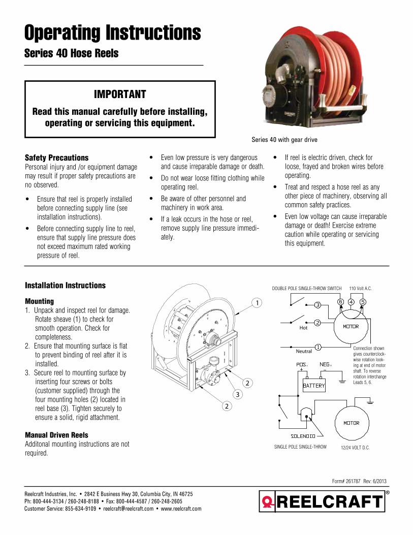
Read this manual carefully before installing, operating or servicing this equipment.
Operating InstructionsSeries 40 Hose Reels
Reelcraft Industries, Inc. • 2842 E Business Hwy 30, Columbia City, IN 46725Ph: 800-444-3134 / 260-248-8188 • Fax: 800-444-4587 / 260-248-2605Customer Service: 855-634-9109 • [email protected] • www.reelcraft.com
Form# 261787 Rev: 6/2013
Series 40 with gear drive
Safety PrecautionsPersonal injury and /or equipment damage may result if proper safety precautions are no observed.
• Ensure that reel is properly installed before connecting supply line (see installation instructions).•
• Before connecting supply line to reel, ensure that supply line pressure does not exceed maximum rated working pressure of reel.
• Even low pressure is very dangerous and cause irreparable damage or death.•
• Do not wear loose fitting clothing while operating reel.•
• Be aware of other personnel and machinery in work area.•
• If a leak occurs in the hose or reel, remove supply line pressure immedi-ately.•
• •
• If reel is electric driven, check for loose, frayed and broken wires before operating.•
• Treat and respect a hose reel as any other piece of machinery, observing all common safety practices.•
• Even low voltage can cause irreparable damage or death! Exercise extreme caution while operating or servicing this equipment.
Installation Instructions
Mounting1. Unpack and inspect reel for damage. Rotate sheave (1) to check for smooth operation. Check for completeness.2. Ensure that mounting surface is flat to prevent binding of reel after it is installed.3. Secure reel to mounting surface by inserting four screws or bolts (customer supplied) through the four mounting holes (2) located in reel base (3). Tighten securely to ensure a solid, rigid attachment.
Manual Driven ReelsAdditonal mounting instructions are not required.
Hot
Neutral
SINGLE POLE SINGLE-THROW
DOUBLE POLE SINGLE-THROW SWITCH
Connection shown gives counterclock-wise rotation look-ing at end of motor shaft. To reverse rotation interchange Leads 5, 6.
12/24 VOLT D.C.
110 Volt A.C.
Series 40 Hose Reels
Page 2 www.reelcraft.com
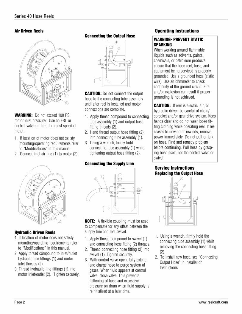
Air Driven Reels
WARNING: Do not exceed 100 PSI motor inlet pressure. Use an FRL or control valve (in line) to adjust speed of motor.
1. If location of motor does not satisfy mounting/operating requirements refer to “Modifications” in this manual.2. Connect inlet air line (1) to motor (2).
Hydraulic Driven Reels1. If location of motor does not satisfy mounting/operating requirements refer to “Modifications” in this manual.2. Apply thread compound to inlet/outlet hydraulic line fittings (1) and motor inlet threads (2).3. Thread hydraulic line fittings (1) into motor inlet/outlet (2). Tighten securely.
Connecting the Output Hose
CAUTION: Do not connect the output hose to the connecting tube assembly until after reel is installed and motor connections are complete.
1. Apply thread compound to connecting tube assembly (1) and output hose fitting threads (2).2. Hand thread output hose fitting (2) into connecting tube assembly (1).3. Using a wrench, firmly hold connecting tube assembly (1) while tightening output hose fitting (2).
Connecting the Supply Line
NOTE: A flexible coupling must be used to compensate for any offset between the supply line and reel swivel.
1. Apply thread compound to swivel (1) and connecting hose fitting (2) threads.2. Thread connecting hose fitting (2) into swivel (1). Tighten securely.3. With control valve open, fully extend and charge hose to purge system of gases. When fluid appears at control valve, close valve. This prevents flattening of hose and excessive pressure on drum when fluid supply is reinitialized at a later time.
Operating Instructions
Service InstructionsReplacing the Output Hose
1. Using a wrench, firmly hold the connecting tube assembly (1) while removing the connecting hose fitting (2).2. To install new hose, see “Connecting Output Hose” in Installation Instructions.
2
1
WARNING- PREVENT STATIC SPARKINGWhen working around flammable liquids such as solvents, paints, chemicals, or petroleum products, ensure that the hose reel, hose, and equipment being serviced is properly grounded. Use a grounded hose (static wire). Use an ohmmeter to check continuity of the ground circuit. Fire and/or explosion can result if proper grounding is not achieved.
CAUTION: If reel is electric, air, or hydraulic driven be careful of chain/sprocket and/or gear drive system. Keep hands clear and do not wear loose fit-ting clothing while operating reel. If reel ceases to unwind or rewinds, remove power immediately. Do not pull or jerk on hose. Find and remedy problem before continuing. Pull hose by grasp-ing hose itself, not the control valve or swivel.
Series 40 Hose Reels
www.reelcraft.com Page 3
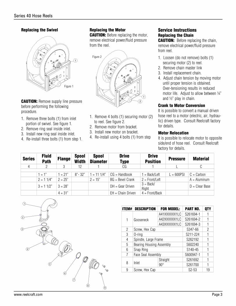
Replacing the Swivel
CAUTION: Remove supply line pressure before performing the following procedure.
1. Remove three bolts (1) from inlet portion of swivel. See figure 1.2. Remove ring seal inside inlet.3. Install new ring seal inside inlet.4. Re-install three bolts (1) from step 1.
Replacing the MotorCAUTION: Before replacing the motor, remove electrical power/fluid pressure from the reel.
1. Remove 4 bolts (1) securing motor (2) to reel. See figure 2.2. Remove motor from bracket.3. Install new motor on bracket.4. Re-install using 4 bolts (1) from step
Service InstructionsReplacing the ChainCAUTION: Before replacing the chain, remove electrical power/fluid pressure from reel.
1. Loosen (do not remove) bolts (1) securing motor (2) to reel.2. Remove chain master link3. Install replacement chain.4. Adjust chain tension by moving motor until proper tension is obtained. Over-tensioning results in reduced motor life. Adjust to allow between ¼” and ½” play in chain.
Crank to Motor ConversionIt is possible to convert a manual driven hose reel to a motor (electric, air, hydrau-lic) driven type. Consult Reelcraft factory for details.
Motor RelocationIt is possible to relocate motor to opposite side/end of hose reel. Consult Reelcraft factory for details.
Series FluidPath Flange Spool
WidthSpool
DiameterDriveType
Drive Position Pressure Material
4 2 3 12 1 CG 1 L C
1 = 1” 1 = 21” 8”- 32” 1 = 11 1/4” CG = Handbook 1 = Back/Left L = 600PSI C = Carbon2 = 1 1/4” 2 = 25” 2 = 15” BG = Bevel Crank 2 = Front/Left A = Aluminum
3 = 1 1/2” 3 = 28” DH = Gear Driven3 = Back/Right
D = Clear Base
4 = 31” EH = Chain Driven 4 = Front/Back
Figure 1
Figure 2
ITEM# DESCRIPTION FOR MODEL: PART NO. QTY
1 Gooseneck
A41XXXXXX1LC S261694-1 1 A42XXXXXX1LC S261694-2 1 A43XXXXXX1LC S261694-3 1
2 Screw, Hex Cap S347-66 23 O-ring S211-224 14 Spindle, Large Frame S262192 15 Bearing Housing Assembly S602240 16 Snap Ring S140-45 17 Face Seal Assembly S600947-1 1
8 Inlet Straight S261692 1 90° S261700 1
9 Screw, Hex Cap S2-53 19
Series 40 Hose Reels
Page 4 www.reelcraft.com
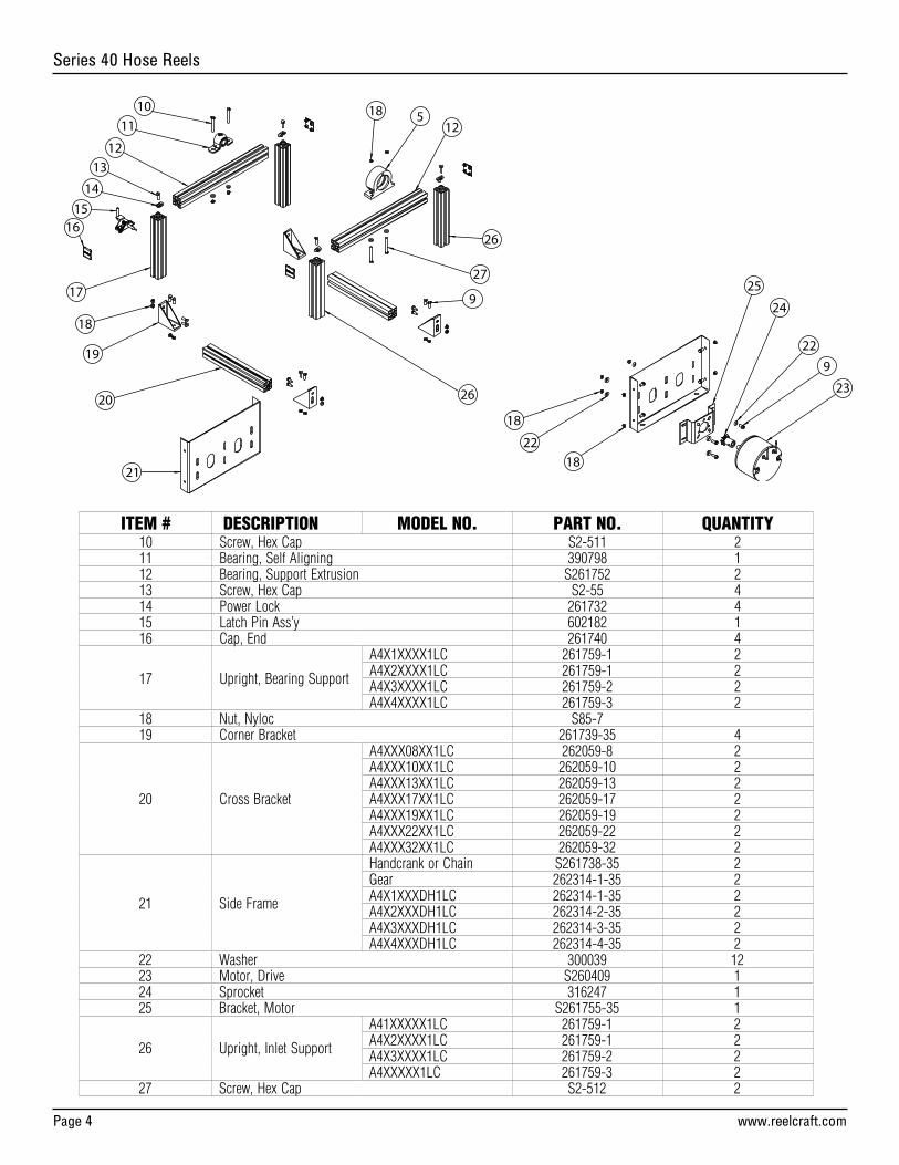
ITEM # DESCRIPTION MODEL NO. PART NO. QUANTITY10 Screw, Hex Cap S2-511 211 Bearing, Self Aligning 390798 112 Bearing, Support Extrusion S261752 213 Screw, Hex Cap S2-55 414 Power Lock 261732 415 Latch Pin Ass’y 602182 116 Cap, End 261740 4
17 Upright, Bearing Support
A4X1XXXX1LC 261759-1 2A4X2XXXX1LC 261759-1 2A4X3XXXX1LC 261759-2 2A4X4XXXX1LC 261759-3 2
18 Nut, Nyloc S85-719 Corner Bracket 261739-35 4
20 Cross Bracket
A4XXX08XX1LC 262059-8 2A4XXX10XX1LC 262059-10 2A4XXX13XX1LC 262059-13 2A4XXX17XX1LC 262059-17 2A4XXX19XX1LC 262059-19 2A4XXX22XX1LC 262059-22 2A4XXX32XX1LC 262059-32 2
21 Side Frame
Handcrank or Chain S261738-35 2Gear 262314-1-35 2A4X1XXXDH1LC 262314-1-35 2A4X2XXXDH1LC 262314-2-35 2A4X3XXXDH1LC 262314-3-35 2A4X4XXXDH1LC 262314-4-35 2
22 Washer 300039 1223 Motor, Drive S260409 124 Sprocket 316247 125 Bracket, Motor S261755-35 1
26 Upright, Inlet Support
A41XXXXX1LC 261759-1 2A4X2XXXX1LC 261759-1 2A4X3XXXX1LC 261759-2 2A4XXXXX1LC 261759-3 2
27 Screw, Hex Cap S2-512 2
Series 40 Hose Reels
www.reelcraft.com Page 5
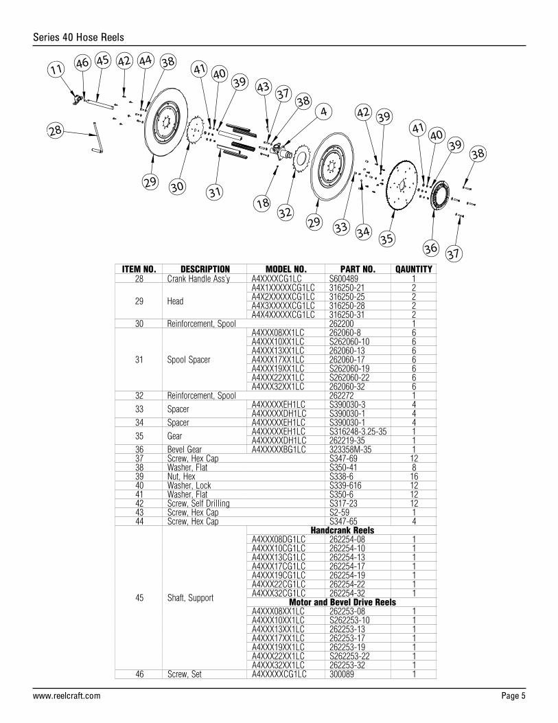
ITEM NO. DESCRIPTION MODEL NO. PART NO. QAUNTITY28 Crank Handle Ass’y A4XXXXCG1LC S600489 1
29 Head
A4X1XXXXXCG1LC 316250-21 2A4X2XXXXXCG1LC 316250-25 2A4X3XXXXXCG1LC 316250-28 2A4X4XXXXXCG1LC 316250-31 2
30 Reinforcement, Spool 262200 1
31 Spool Spacer
A4XXX08XX1LC 262060-8 6A4XXX10XX1LC S262060-10 6A4XXX13XX1LC 262060-13 6A4XXX17XX1LC 262060-17 6A4XXX19XX1LC S262060-19 6A4XXX22XX1LC S262060-22 6A4XXX32XX1LC 262060-32 6
32 Reinforcement, Spool 262272 1
33 Spacer A4XXXXXEH1LC S390030-3 4A4XXXXXDH1LC S390030-1 4
34 Spacer A4XXXXXEH1LC S390030-1 4
35 Gear A4XXXXXEH1LC S316248-3.25-35 1A4XXXXXDH1LC 262219-35 1
36 Bevel Gear A4XXXXXBG1LC 323358M-35 137 Screw, Hex Cap S347-69 1238 Washer, Flat S350-41 839 Nut, Hex S338-6 1640 Washer, Lock S339-616 1241 Washer, Flat S350-6 1242 Screw, Self Drilling S317-23 1243 Screw, Hex Cap S2-59 144 Screw, Hex Cap S347-65 4
45 Shaft, Support
Handcrank ReelsA4XXX08DG1LC 262254-08 1A4XXX10CG1LC 262254-10 1A4XXX13CG1LC 262254-13 1A4XXX17CG1LC 262254-17 1A4XXX19CG1LC 262254-19 1A4XXX22CG1LC 262254-22 1A4XXX32CG1LC 262254-32 1
Motor and Bevel Drive ReelsA4XXX08XX1LC 262253-08 1A4XXX10XX1LC S262253-10 1A4XXX13XX1LC 262253-13 1A4XXX17XX1LC 262253-17 1A4XXX19XX1LC 262253-19 1A4XXX22XX1LC S262253-22 1A4XXX32XX1LC 262253-32 1
46 Screw, Set A4XXXXXCG1LC 300089 1