
REDWALL-V adjustment procedures guide - OPTEX · PDF fileREDWALL-V adjustment procedures...
18
Requirements This document is provided as a reference tool for installing the Optex Redwall SIP passive infrared detector. Before starting, read the instruction book that comes with the unit. SIP detector main unit Cross slot Screwdriver Page 1/18 REDWALL-V adjustment procedures guide Ver1.2 July 1. 2011 *Included in the kit Area plate Area masking seal Allen Key Tweezers *Optional (but necessary) adjustment tools AVF-1 Area View Finder AWT-3 Area Walk Tester *Other useful tools Measure wheel Before starting any installation, please confirm if proper power is provided to the SIP unit. Volt meter
Transcript of REDWALL-V adjustment procedures guide - OPTEX · PDF fileREDWALL-V adjustment procedures...
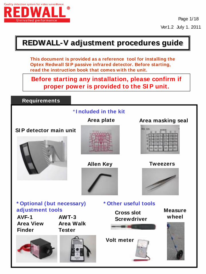
Requirements
This document is provided as a reference tool for installing the Optex Redwall SIP passive infrared detector. Before starting, read the instruction book that comes with the unit.
SIP detector main unit
Cross slot Screwdriver
Page 1/18
REDWALL-V adjustment procedures guide
Ver1.2 July 1. 2011
*Included in the kit
Area plate Area masking seal
Allen Key Tweezers
*Optional (but necessary) adjustment tools AVF-1 Area View Finder
AWT-3 Area Walk Tester
*Other useful tools Measure
wheel
Before starting any installation, please confirm if proper power is provided to the SIP unit.
Volt meter
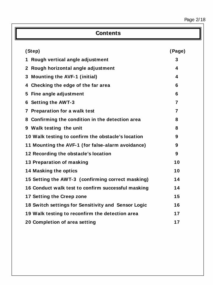
Contents
Page 2/18
(Step)
1 Rough vertical angle adjustment
2 Rough horizontal angle adjustment
3 Mounting the AVF-1 (initial)
4 Checking the edge of the far area
5 Fine angle adjustment
6 Setting the AWT-3
7 Preparation for a walk test
8 Confirming the condition in the detection area
9 Walk testing the unit
10 Walk testing to confirm the obstacle’s location
11 Mounting the AVF-1 (for false-alarm avoidance)
12 Recording the obstacle’s location
13 Preparation of masking
14 Masking the optics
15 Setting the AWT-3 (confirming correct masking)
16 Conduct walk test to confirm successful masking
17 Setting the Creep zone
18 Switch settings for Sensitivity and Sensor Logic
19 Walk testing to reconfirm the detection area
20 Completion of area setting
(Page)
3
4
4
6
6
7
7
8
8
9
9
9
10
10
14
14
15
16
17
17
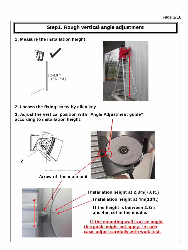
Step1. Rough vertical angle adjustment
Page 3/18
1. Measure the installation height.
2. Loosen the fixing screw by allen key.
3. Adjust the vertical position with “Angle Adjustment guide” according to installation height.
Arrow of the main unit
Installation height at 2.3m(7.6ft.)
Installation height at 4m(13ft.)
If the height is between 2.3m and 4m, set in the middle.
2
If the mounting wall is at an angle, this guide might not apply. In such case, adjust carefully with walk test.
Page 4/18
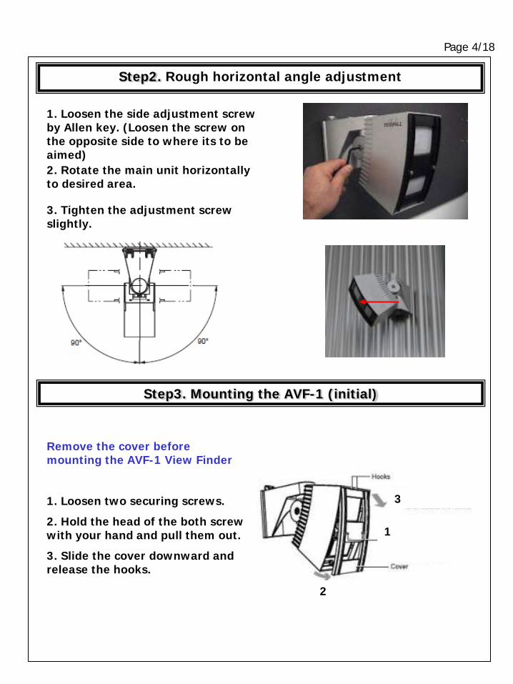
1. Loosen the side adjustment screw by Allen key. (Loosen the screw on the opposite side to where its to be aimed) 2. Rotate the main unit horizontally to desired area.
3. Tighten the adjustment screw slightly.
Remove the cover before mounting the AVF-1 View Finder
1. Loosen two securing screws.
2. Hold the head of the both screw with your hand and pull them out.
3. Slide the cover downward and release the hooks.
3
1
2
Step2. Rough horizontal angle adjustment
Step3. Mounting the AVF-1 (initial)
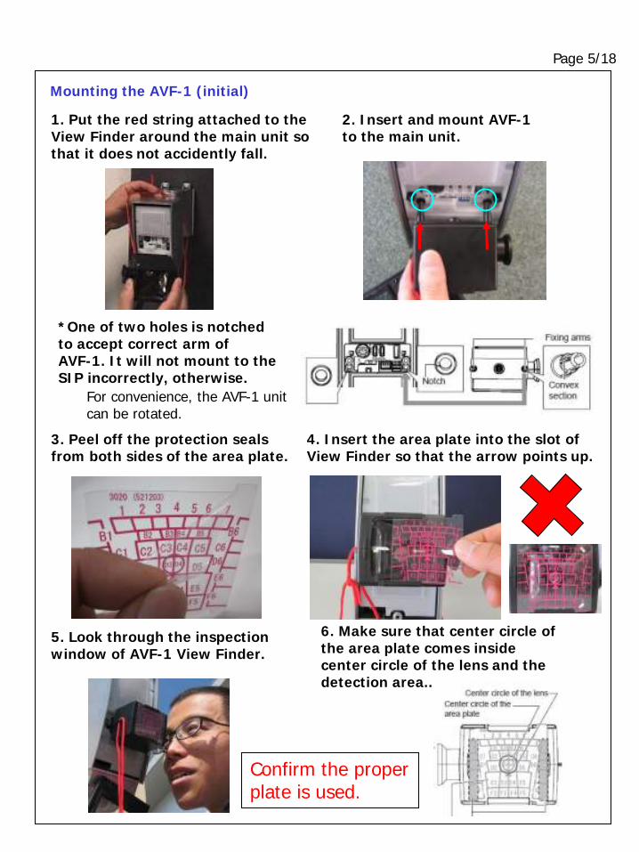
Page 5/18
1. Put the red string attached to the View Finder around the main unit so that it does not accidently fall.
*One of two holes is notched to accept correct arm of AVF-1. It will not mount to the SIP incorrectly, otherwise.
2. Insert and mount AVF-1 to the main unit.
3. Peel off the protection seals from both sides of the area plate.
4. Insert the area plate into the slot of View Finder so that the arrow points up.
5. Look through the inspection window of AVF-1 View Finder.
6. Make sure that center circle of the area plate comes inside center circle of the lens and the detection area..
Mounting the AVF-1 (initial)
Confirm the proper plate is used.
For convenience, the AVF-1 unit can be rotated.
Page 6/18
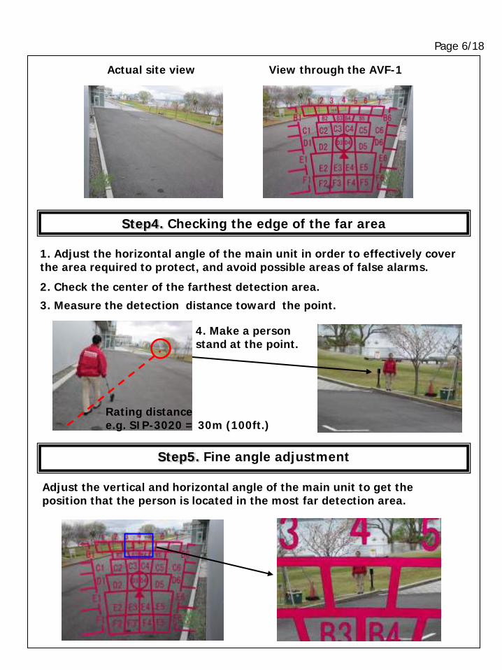
Step4. Checking the edge of the far area
Step5. Fine angle adjustment
3. Measure the detection distance toward the point.
Adjust the vertical and horizontal angle of the main unit to get the position that the person is located in the most far detection area.
4. Make a person stand at the point.
Actual site view View through the AVF-1
1. Adjust the horizontal angle of the main unit in order to effectively cover the area required to protect, and avoid possible areas of false alarms.
2. Check the center of the farthest detection area.
Rating distance e.g. SIP-3020 = 30m (100ft.)
Page 7/18
Dark gray area
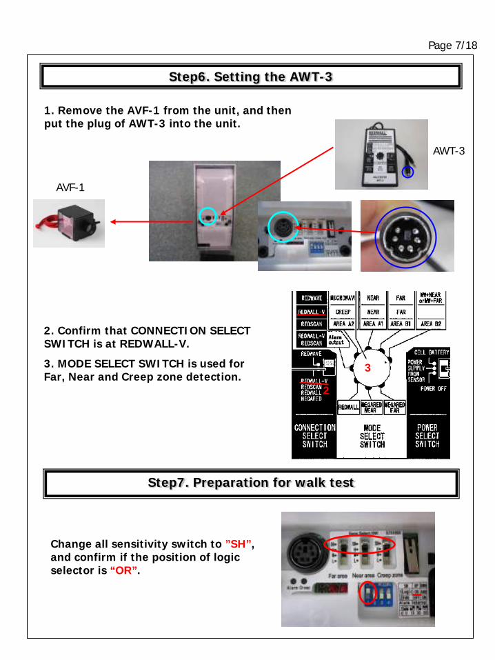
Change all sensitivity switch to ”SH”, and confirm if the position of logic selector is “OR”.
Step7. Preparation for walk test
2. Confirm that CONNECTION SELECT SWITCH is at REDWALL-V.
3. MODE SELECT SWITCH is used for Far, Near and Creep zone detection.
3
2
Step6. Setting the AWT-3
1. Remove the AVF-1 from the unit, and then put the plug of AWT-3 into the unit.
AVF-1
AWT-3
Page 8/18
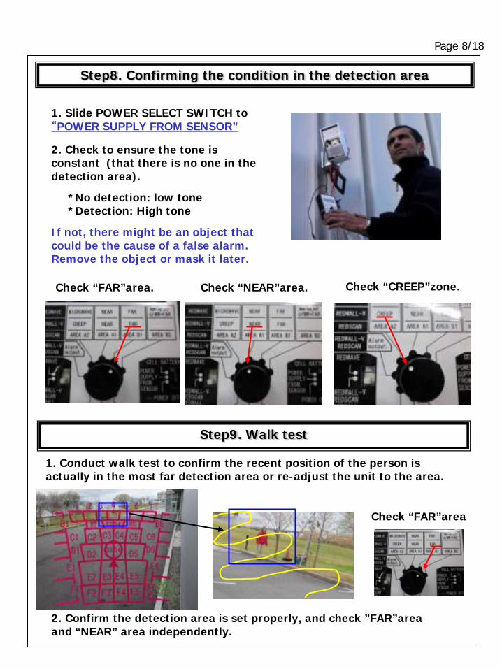
Step9. Walk test
1. Conduct walk test to confirm the recent position of the person is actually in the most far detection area or re-adjust the unit to the area.
Check “FAR”area. Check “NEAR”area. Check “CREEP”zone.
Step8. Confirming the condition in the detection area
2. Check to ensure the tone is constant (that there is no one in the detection area).
If not, there might be an object that could be the cause of a false alarm. Remove the object or mask it later.
1. Slide POWER SELECT SWITCH to “POWER SUPPLY FROM SENSOR”
*No detection: low tone *Detection: High tone
Check “FAR”area
2. Confirm the detection area is set properly, and check ”FAR”area and “NEAR” area independently.
Page 9/18
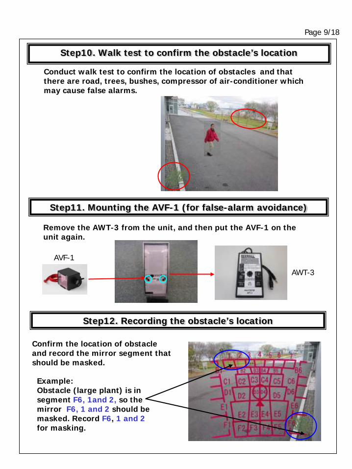
Step12. Recording the obstacle’s location
Confirm the location of obstacle and record the mirror segment that should be masked.
Example: Obstacle (large plant) is in segment F6, 1and 2, so the mirror F6, 1 and 2 should be masked. Record F6, 1 and 2 for masking.
Step11. Mounting the AVF-1 (for false-alarm avoidance)
AVF-1
AWT-3
Remove the AWT-3 from the unit, and then put the AVF-1 on the unit again.
Conduct walk test to confirm the location of obstacles and that there are road, trees, bushes, compressor of air-conditioner which may cause false alarms.
Step10. Walk test to confirm the obstacle’s location
Page 10/18
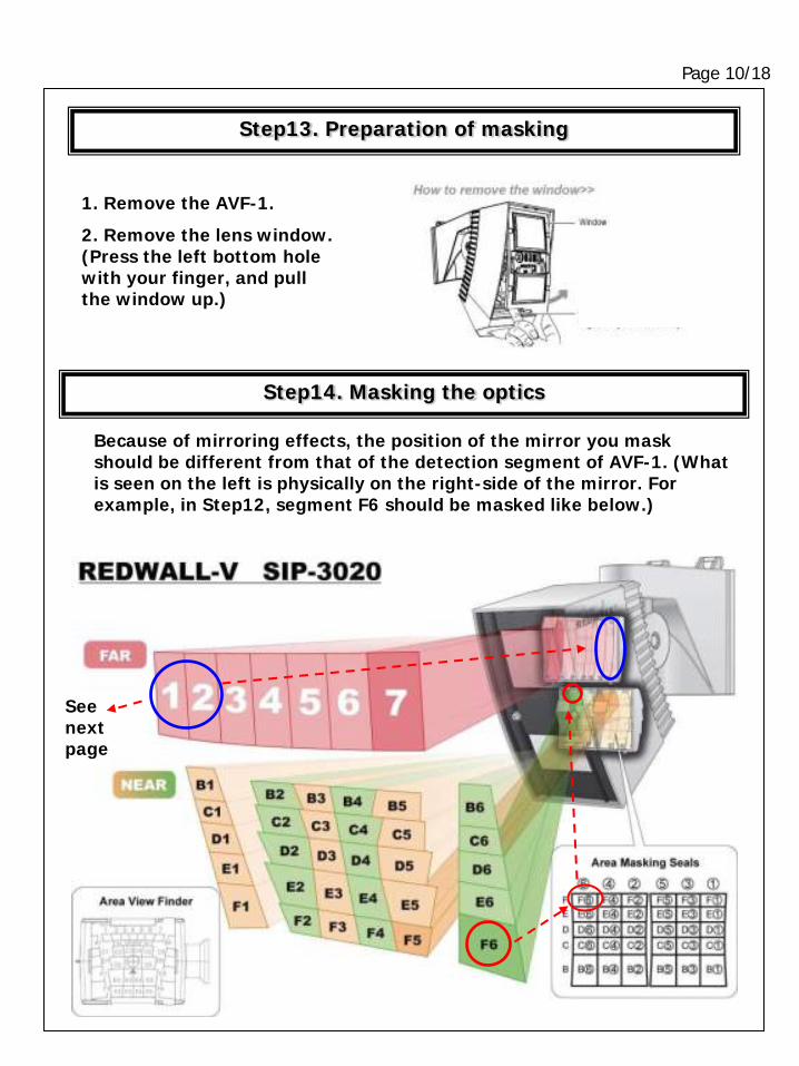
Step14. Masking the optics
Because of mirroring effects, the position of the mirror you mask should be different from that of the detection segment of AVF-1. (What is seen on the left is physically on the right-side of the mirror. For example, in Step12, segment F6 should be masked like below.)
1. Remove the AVF-1.
2. Remove the lens window. (Press the left bottom hole with your finger, and pull the window up.)
Step13. Preparation of masking
See next page
Page 11/18
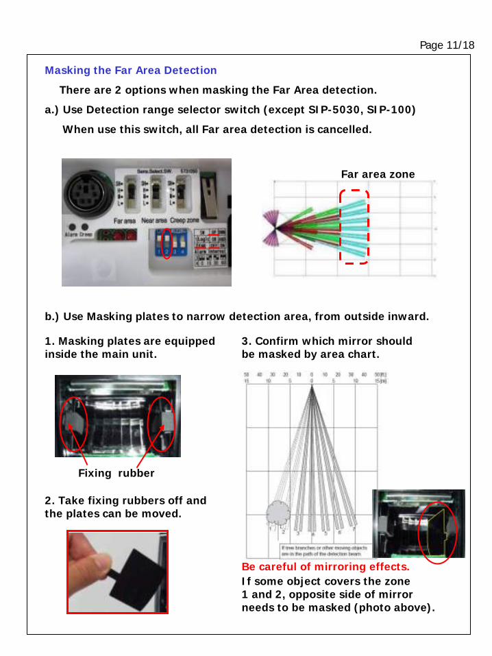
b.) Use Masking plates to narrow detection area, from outside inward.
1. Masking plates are equipped inside the main unit.
2. Take fixing rubbers off and the plates can be moved.
Fixing rubber
3. Confirm which mirror should be masked by area chart.
If some object covers the zone 1 and 2, opposite side of mirror needs to be masked (photo above).
Masking the Far Area Detection
There are 2 options when masking the Far Area detection.
a.) Use Detection range selector switch (except SIP-5030, SIP-100)
When use this switch, all Far area detection is cancelled.
Far area zone
Be careful of mirroring effects.
Page 12/18
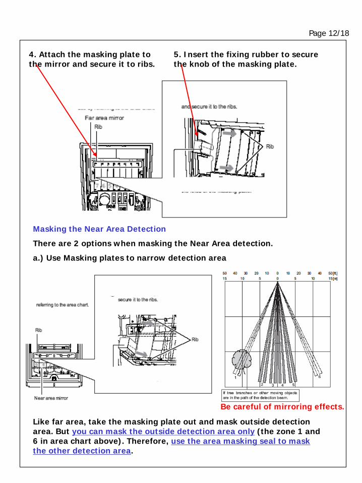
4. Attach the masking plate to the mirror and secure it to ribs.
5. Insert the fixing rubber to secure the knob of the masking plate.
Masking the Near Area Detection
There are 2 options when masking the Near Area detection.
a.) Use Masking plates to narrow detection area
Like far area, take the masking plate out and mask outside detection area. But you can mask the outside detection area only (the zone 1 and 6 in area chart above). Therefore, use the area masking seal to mask the other detection area.
Be careful of mirroring effects.
Page 13/18
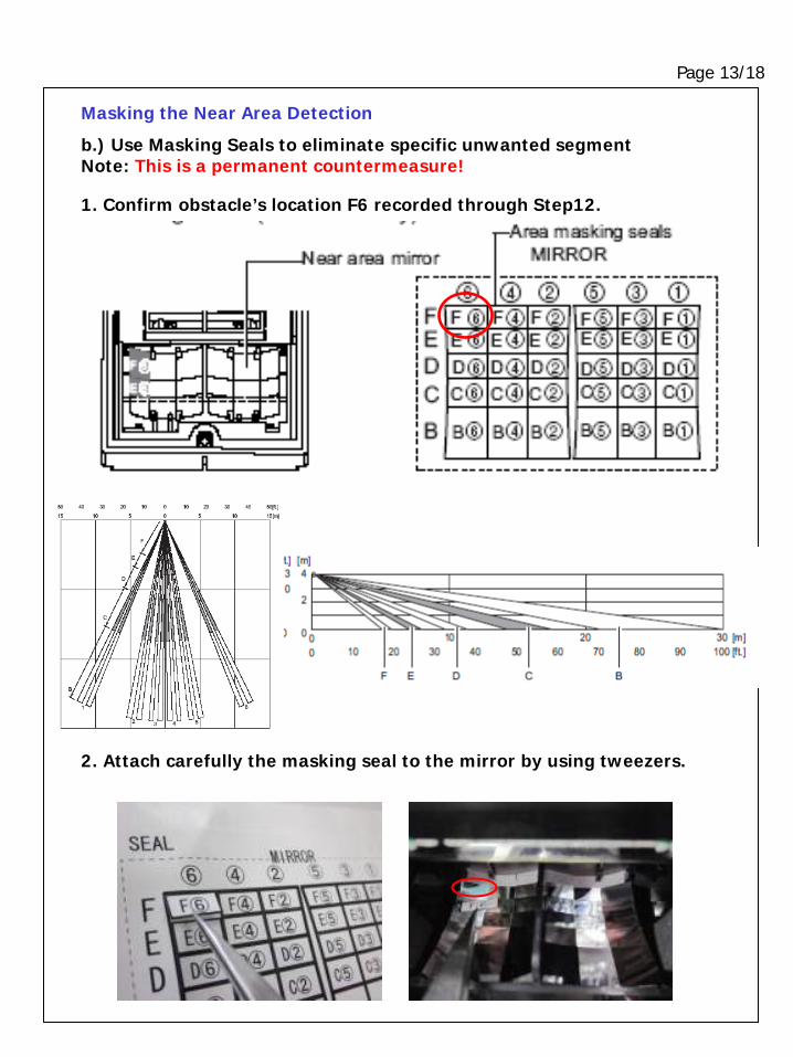
Masking the Near Area Detection
b.) Use Masking Seals to eliminate specific unwanted segment Note: This is a permanent countermeasure!
1. Confirm obstacle’s location F6 recorded through Step12.
2. Attach carefully the masking seal to the mirror by using tweezers.
Page 14/18
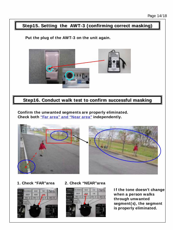
Step15. Setting the AWT-3 (confirming correct masking)
Put the plug of the AWT-3 on the unit again.
Step16. Conduct walk test to confirm successful masking
Confirm the unwanted segments are properly eliminated. Check both “Far area” and “Near area” independently.
If the tone doesn’t change when a person walks through unwanted segment(s), the segment is properly eliminated.
1. Check “FAR”area 2. Check “NEAR”area
Page 15/18
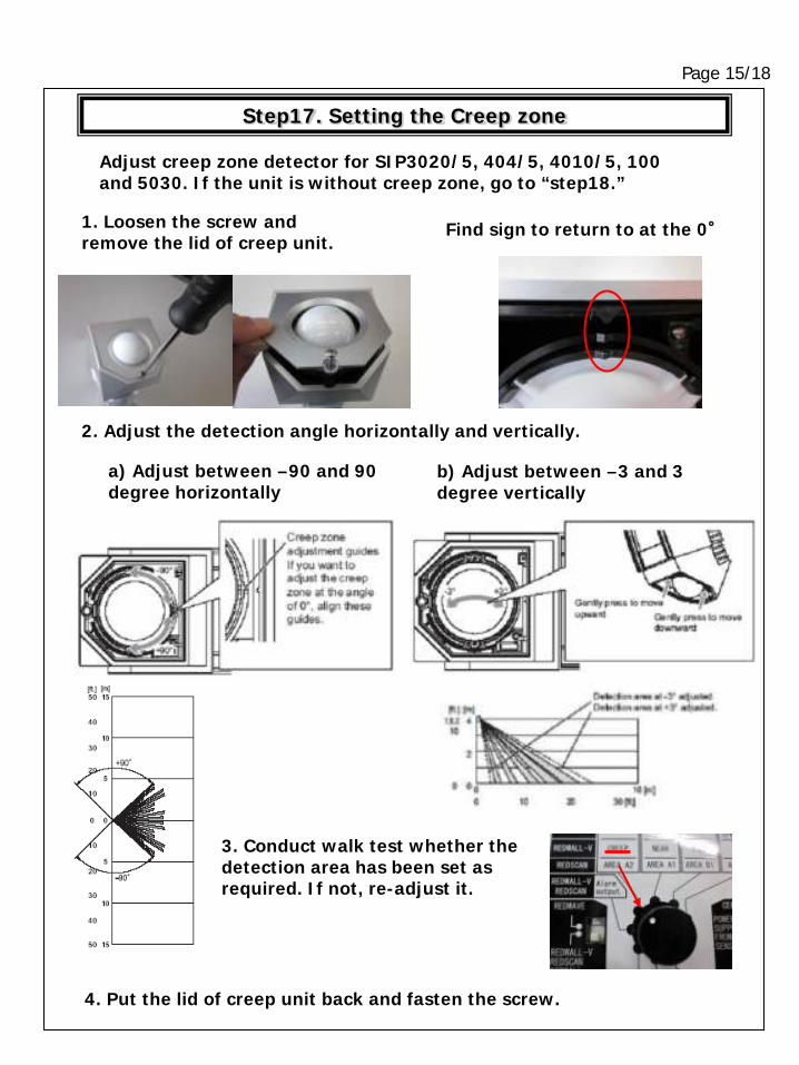
Step17. Setting the Creep zone
Adjust creep zone detector for SIP3020/5, 404/5, 4010/5, 100 and 5030. If the unit is without creep zone, go to “step18.”
1. Loosen the screw and remove the lid of creep unit.
2. Adjust the detection angle horizontally and vertically.
3. Conduct walk test whether the detection area has been set as required. If not, re-adjust it.
4. Put the lid of creep unit back and fasten the screw.
a) Adjust between –90 and 90 degree horizontally
b) Adjust between –3 and 3 degree vertically
Find sign to return to at the 0°
Page 16/18
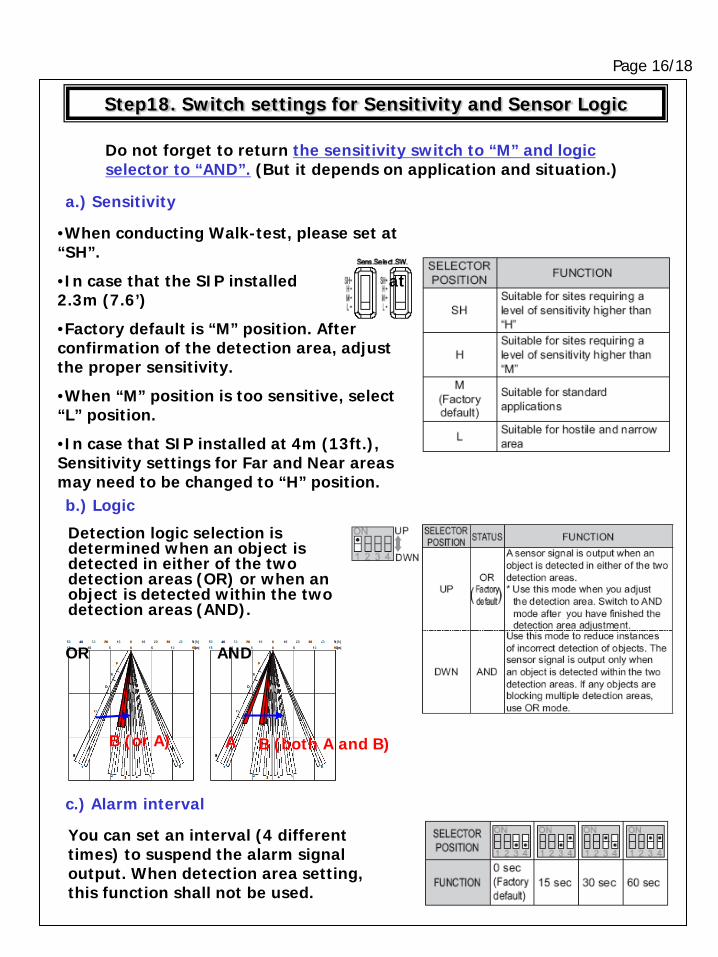
Step18. Switch settings for Sensitivity and Sensor Logic
Do not forget to return the sensitivity switch to “M” and logic selector to “AND”. (But it depends on application and situation.)
A B (both A and B) B (or A)
Detection logic selection is determined when an object is detected in either of the two detection areas (OR) or when an object is detected within the two detection areas (AND).
•When conducting Walk-test, please set at “SH”.
•In case that the SIP installed at 2.3m (7.6’)
•Factory default is “M” position. After confirmation of the detection area, adjust the proper sensitivity.
•When “M” position is too sensitive, select “L” position.
•In case that SIP installed at 4m (13ft.), Sensitivity settings for Far and Near areas may need to be changed to “H” position.
a.) Sensitivity
b.) Logic
c.) Alarm interval
You can set an interval (4 different times) to suspend the alarm signal output. When detection area setting, this function shall not be used.
OR AND
Page 17/18
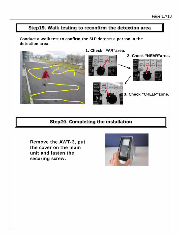
Step20. Completing the installation
Remove the AWT-3, put the cover on the main unit and fasten the securing screw.
Step19. Walk testing to reconfirm the detection area
Conduct a walk test to confirm the SIP detects a person in the detection area.
1. Check “FAR”area. 2. Check “NEAR”area.
3. Check “CREEP”zone.
Page 18/18
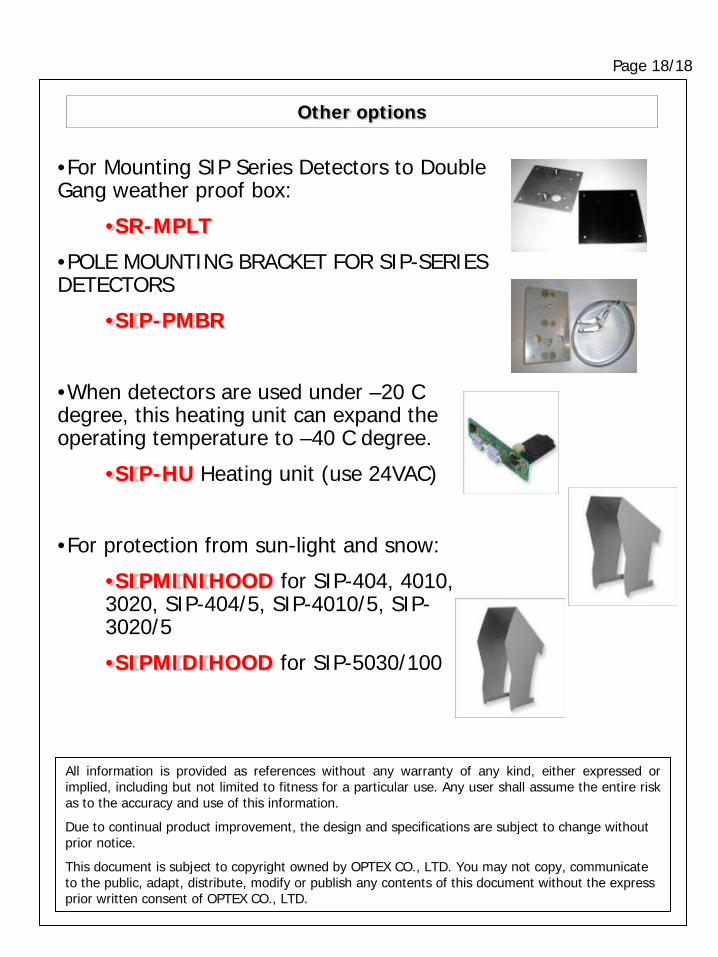
Other options
All information is provided as references without any warranty of any kind, either expressed or implied, including but not limited to fitness for a particular use. Any user shall assume the entire risk as to the accuracy and use of this information.
Due to continual product improvement, the design and specifications are subject to change without prior notice.
This document is subject to copyright owned by OPTEX CO., LTD. You may not copy, communicate to the public, adapt, distribute, modify or publish any contents of this document without the express prior written consent of OPTEX CO., LTD.
•For Mounting SIP Series Detectors to Double Gang weather proof box:
•SR-MPLT
•POLE MOUNTING BRACKET FOR SIP-SERIES DETECTORS
•SIP-PMBR
•When detectors are used under –20 C degree, this heating unit can expand the operating temperature to –40 C degree.
•SIP-HU Heating unit (use 24VAC)
•For protection from sun-light and snow:
•SIPMINIHOOD for SIP-404, 4010, 3020, SIP-404/5, SIP-4010/5, SIP-3020/5
•SIPMIDIHOOD for SIP-5030/100


![Jacques, Brian - [Redwall 01] - Redwall](https://static.fdocuments.in/doc/165x107/54fe61474a7959592e8b4873/jacques-brian-redwall-01-redwall.jpg)