Reduction of Structural Loads Using Maneuver Load Control ... · Reduction of Structural Loads...
38
NASA-TM-4526 19940019822 NASA Technical Memorandum 4526 Reduction of Structural Loads Using Maneuver Load Control on the Advanced Fighter Technology Integration (AFTI)/F-111 Mission Adaptive Wing Stephen V. Thornton September 1993 , https://ntrs.nasa.gov/search.jsp?R=19940019822 2018-07-13T23:12:15+00:00Z
Transcript of Reduction of Structural Loads Using Maneuver Load Control ... · Reduction of Structural Loads...
NASA-TM-4526 19940019822
NASA Technical Memorandum 4526
Reduction of StructuralLoads Using ManeuverLoad Control on theAdvanced FighterTechnology Integration(AFTI)/F-111 MissionAdaptive Wing
Stephen V. Thornton
September 1993 ,
https://ntrs.nasa.gov/search.jsp?R=19940019822 2018-07-13T23:12:15+00:00Z

J
J_lr_iiiiiiiiii_iiiI3 1176 01409 6078
NASA Technical Memorandum 4526
Reduction of StructuralLoads Using ManeuverLoad Control on theAdvanced FighterTechnology Integration(AFTI)/F-111 MissionAdaptive Wing
Stephen V. ThorntonDryden Flight Research FacilityEdwards, California
NationalAeronauticsandSpaceAdministrationOfficeofManagementScientificandTechnicalInformationProgram1993
..... r ,

CONTENTS
ABSTRACT 1
NOMENCLATURE 1
INTRODUCTION 2
AIRCRAFT DESCRIPTION 4
INSTRUMENTATION 7
FLIGHT TEST CONDITIONS 10
RESULTS AND DISCUSSION 11
Wing-Root Loads ............................................................... 12Wing-Box Loads ............................................................... 17High-Camber Configurations ...................................................... 20Forward Spar Web Shear ......................................................... 21Stabilator Pitch Trim Loads ....................................................... 21Automatic Modes ............................................................... 23
CONCLUDING REMARKS 27
REFERENCES 28
°°°
111


ABSTRACT
A transonic fighter-bomber aircraft, having a swept supercritical wing with smooth variable-camberflaps was fitted with a maneuver load control (MLC) system that implements a technique to reduce theinboard bending moments in the wing by shifting the spanwise load distribution inboard as load factor in-creases. The technique modifies the spanwise camber distribution by automatically commanding flap po-sition as a function of flap position, true airspeed, Mach number, dynamic pressure, normal acceleration,and wing sweep position. Flight test structural loads data were obtained for loads in both the wing box andthe wing root. Data from uniformly deflected flaps were compared with data from flaps in the MLC con-figuration where the outboard segment of three flap segments was deflected downward less than the twoinboard segments. The changes in the shear loads in the forward wing spar and at the roots of the stabilatorsalso are presented. The camber control system automatically reconfigures the flaps through varied flightconditions. Configurations having both moderate and full trailing-edge flap deflection were tested. Flighttest data were collected at Mach numbers of 0.6, 0.7, 0.8, and 0.9 and dynamic pressures of 300, 450, 600,and 800 lb/ft 2. The Reynolds numbers for these flight conditions ranged from 26 x 106 to 54 × 106 at themean aerodynamic chord. Load factor increases of up to 1.0 g were achieved with no increase in wing-rootbending moment with the MLC flap configuration.
NOMENCLATURE
Physical quantities in this report are given in the U.S. customary system of units. Reference I gives thefactors for conversion to the international system of units.
AFTI advanced fighter technology integration
B wing-root bending moment, in-lb
Co coefficient of drag
CCC cruise camber control
c.g. aircraft center of gravity location, in.
CL coefficient of lift
g gravitational constant, 32.2 ft/sec 2
ge equivalent load factor = maneuver gross weight × load factordesign gross weight (70,000 lb)
L/D lift-to-drag ratio, (C L/CD)
M Mach number
MAC mean aerodynamic chord
MAW mission adaptive wing
MEGA maneuver enhancement/gust alleviation
MCC maneuver camber control
MLC maneuver load control
nz normal acceleration, g
[
free-streamdynamic pressure,lb/ft2
T wing-roottorsion,in-lbTACT transonicaircrafttechnology
W aircraft gross weight, lb
a aircraftangle of attack,deg
8h pitch stabilatordeflection;wailing edge down is positive (average of left and right stabilatordeflections), deg
8LE deflection of the leading-edge flap; down is positive, deg
&rE deflection of the midspan and inboardtrailing-edgeflaps;down is positive, deg
&lEO deflection of the outboardwailing-edge flap; down is positive, deg
INTRODUCTION
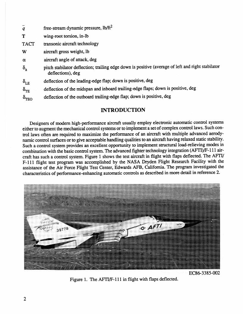
Designersof modemhigh-performanceaircraftusuallyemployelectronicautomaticcontrolsystemseitherto augmentthemechanicalcontrolsystemsortoimplementa setofcomplexcontrollaws.Suchcon-trollawsoftenarerequiredto maximizethe performanceof an aircraftwith multipleadvancedaerody-namiccontrolsurfacesor to giveacceptablehandlingqualitiestoanaircrafthavingrelaxedstaticstability.Sucha controlsystemprovidesan excellentopportunityto implementstructuralload-relievingmodesincombinationwiththebasiccontrolsystem.Theadvancedfightertechnologyintegration(AFH)/F-111air-crafthassucha controlsystem.Figure1 showsthe testaircraftin flightwith flapsdeflected.TheAFFI/F-111 flighttest programwas accomplishedby the NASADrydenFlightResearchFacility with theassistanceof the AirForceFlightTest Center,EdwardsAFB,California.The programinvestigatedthecharacteristicsof performance-enhancingautomaticcontrolsasdescribedin moredetailin reference2.
EC86-3385-002
Figure 1. The AFT!/F-111 in flight with flapsdeflected.
2
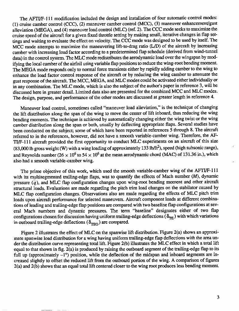
The AFTI/F- 111 modification included the design and installation of four automatic control modes:(1) cruise camber control (CCC), (2) maneuver camber control (MCC), (3) maneuver enhancement/gustalleviation (MEGA), and (4) maneuver load control (MLC) (ref. 2). The CCC mode seeks to maximize thecruise speed of the aircraft for a given fixed throttle setting by making small, iterative changes in flap set-tings and waiting to evaluate the effect on velocity. The CCC mode was designed to be used by itself. TheMCC mode attempts to maximize the maneuvering lift-to-drag ratio (L/D) of the aircraft by increasingcamber with increasing load factor according to a predetermined flap schedule (derived from wind-tunneldata) in the control system. The MLC mode redistributes the aerodynamic load over the wingspan by mod-ifying the local camber of the airfoil using variable flap positions to reduce the wing-root bending moment.The MEGA mode responds only to normal force transients either by rapidly adding camber to the wing toenhance the load factor control response of the aircraft or by reducing the wing camber to attenuate thegust response of the aircraft. The MCC, MEGA, and MLC modes could be activated either individually orin any combination. The MLC mode, which is also the subject of the author's paper in reference 3, will bediscussed here in greater detail. Limited data also are presented for the combined MCC and MLC modes.The design, purpose, and performance of the other modes are discussed at greater length in reference 4.
Maneuver load control, sometimes called "maneuver load alleviation," is the technique of changingthe lift distribution along the span of the wing to move the center of lift inboard, thus reducing the wingbending moments. The technique is achieved by automatically changing either the wing twist or the wingcamber distribution along the span or both, usually by deflecting appropriate flaps. Several studies havebeen conducted on the subject; some of which have been reported in references 5 through 8. The aircraftreferred to in the references, however, did not have a smooth variable-camber wing. Therefore, the AF-TI/F-111 aircraft provided the first opportunity to conduct MLC experiments on an aircraft of this size
(83,000 lb gross weight (W) with a wing loading of approximately 133 lb/ft2), speed (high subsonic range), •
and Reynolds number (26 x 106 to 54 x 106 at the mean aerodynamic chord (MAC) of 131.36 in.), whichalso had a smooth variable-camber wing.
The prime objective of this work, which used the smooth variable-camber wing of the AF'TI/F-111with its multisegmented trailing-edge flaps, was to quantify the effects of Mach number (M), dynamicpressure (q), and MLC flap configuration changes upon wing-root bending moment and other aircraftstructural loads. Evaluations are made regarding the pitch trim load changes on the stabilator caused byMLC flap configuration changes. Observations also are made regarding the effects of MLC pitch trimloads upon aircraft performance for selected maneuvers. Aircraft component loads at different combina-tions of leading and trailing-edge flap positions are compared with two baseline flap configurations at sev-eral Mach numbers and dynamic pressures. The term "baseline" designates either of two flapconfigurations chosen for discussion having uniform trailing-edge deflections (_TE) with which variationsin outboard trailing-edge deflections ([iTEo) are compared.
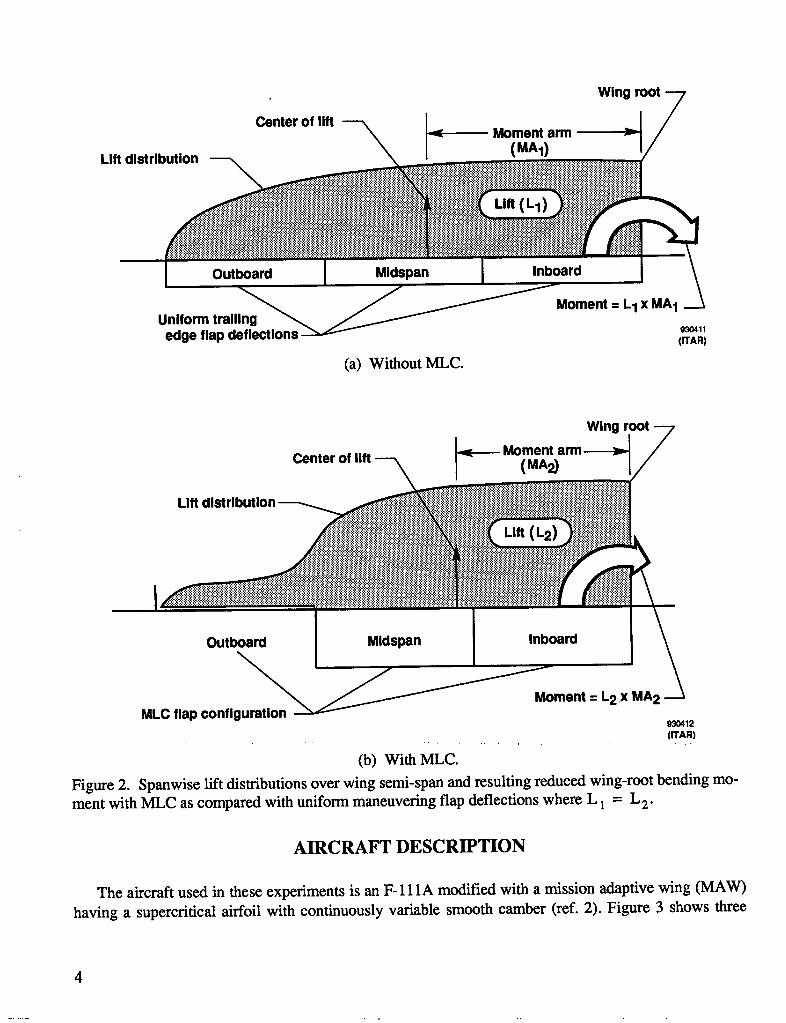
Figure 2 illustrates the effect of MLC on the spanwise lift distribution. Figure 2(a) shows an approxi-mate spanwise load distribution for a wing having uniform trailing-edge flap deflections with the area un-der the distribution curve representing total lift. Figure 2(b) illustrates the MLC effect in which a total liftequal to that shown in fig. 2(a) is produced by raising the outboard segment of the trailing-edge flap to itsfull up (approximately -1 °) position, while the deflection of the midspan and inboard segments are in-creased slightly to offset the reduced lift from the outboard portion of the wing. A comparison of figures2(a) and 2(b) shows that an equal total lift centered closer to the wing root produces less bending moment.
3
Wing root
Center of lift _ Moment arm
Lift distribution _ (MA1)
Lift (L1)
Outboard Midspan Inboard
_Moment = L1 x MA1Uniform trailing _ __edge flap deflections _ 930411(ITAR)
(a) Without MLC.
Wing root
_---- MomentCenter of lift (MA2)
Lift dlst
Lift (L2)
Outboard Mldspan Inboard
_ _ment = L2.x MA2MLC flap configuration 93O412
(ITAR)
(b) WithMLC.Figure 2. Spanwise lift distributions over wing semi-span and resulting reduced wing-root bending mo-ment with MLC as compared with uniform maneuvering flap deflections where L 1 = L2"
AIRCRAFT DESCRIPTION
The aircraft used in these experiments is an F-111A modified with a mission adaptive wing (MAW)
having a supercritical airfoil with continuously variable smooth camber (ref. 2). Figure 3 shows three
4
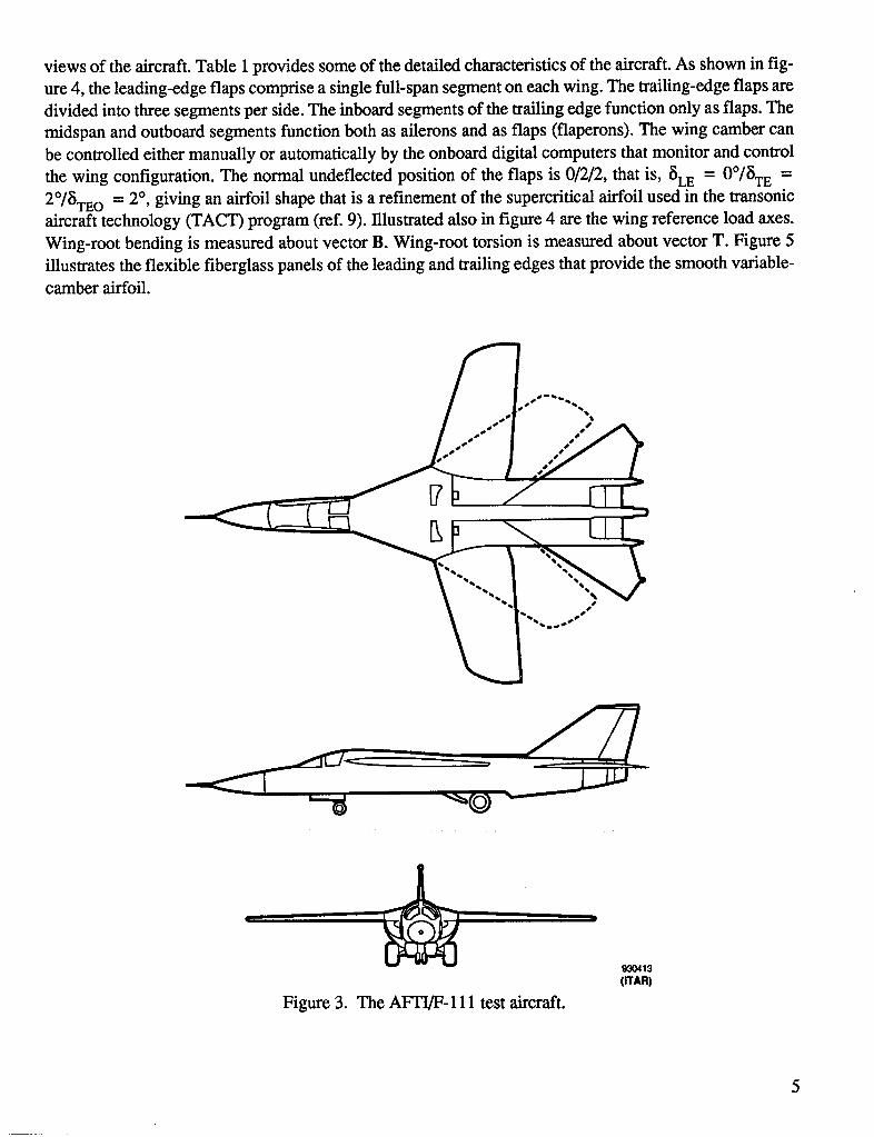
views of the aircraft. Table i provides some of the detailed characteristics of the aircraft. As shown in fig-ure 4, the leading-edge flaps comprise a single full-span segment on each wing. The trailing-edge flaps aredivided into three segments per side. The inboard segments of the trailing edge function only as flaps. Themidspan and outboard segments function both as ailerons and as flaps (flaperons). The wing camber canbe controlled either manually or automatically by the onboard digital computers that monitor and control
the wing configuration. The normal undeflected position of the flaps is 0/2/2, that is, SEE = 0°/STE =
2°/STEO = 2 °, giving an airfoil shape that is a refinement of the supercritical airfoil used in the transonicaircraft technology (TACT) program (ref. 9). Illustrated also in figure 4 are the wing reference load axes.Wing-root bending is measured about vector B. Wing-root torsion is measured about vector T. Figure 5illustrates the flexible fiberglass panels of the leading and trailing edges that provide the smooth variable-camber airfoil.
93O413(ITAR)
Figure 3. The Ab'TI/F-111 test aircraft.
5
. _ • i-¸,
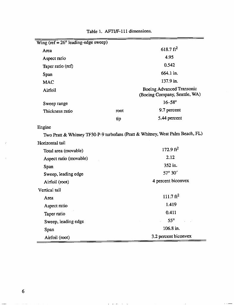
Table 1. AFTI/F-111 dimensions.
Wing (ref = 26 ° leading-edge sweep)
Area 618.7 ft2
Aspect ratio 4.95
Taper ratio (ret) 0.542
Span 664.1 in.
MAC 137.9 in.
Airfoil Boeing Advanced Transonic(Boeing Company, Seattle, WA)
Sweep range 16-58°
Thickness ratio root 9.7 percent
tip 5.44 percent
Engine
Two Pratt & Whitney TF30-P-9 turbofans (Pratt & Whitney, West Palm Beach, FL)
Horizontal tail
Total area (movable) 172.9 ft2
Aspect ratio (movable) 2.12
Span 352 in.
Sweep, leading edge 57° 30'
Airfoil (root) 4 percent biconvex
Vertical tail
Area 111,7 ft2
Aspect ratio 1.419
Taper ratio 0.411
Sweep, leading edge 55°
Span 106.8 in.
Airfoil (root) 3.2 percent biconvex
6
T
-B \ __
Load reference axls ___/ / _'"-T-__Leading-edge flap Trailing-edge flaps
930414(n'An)
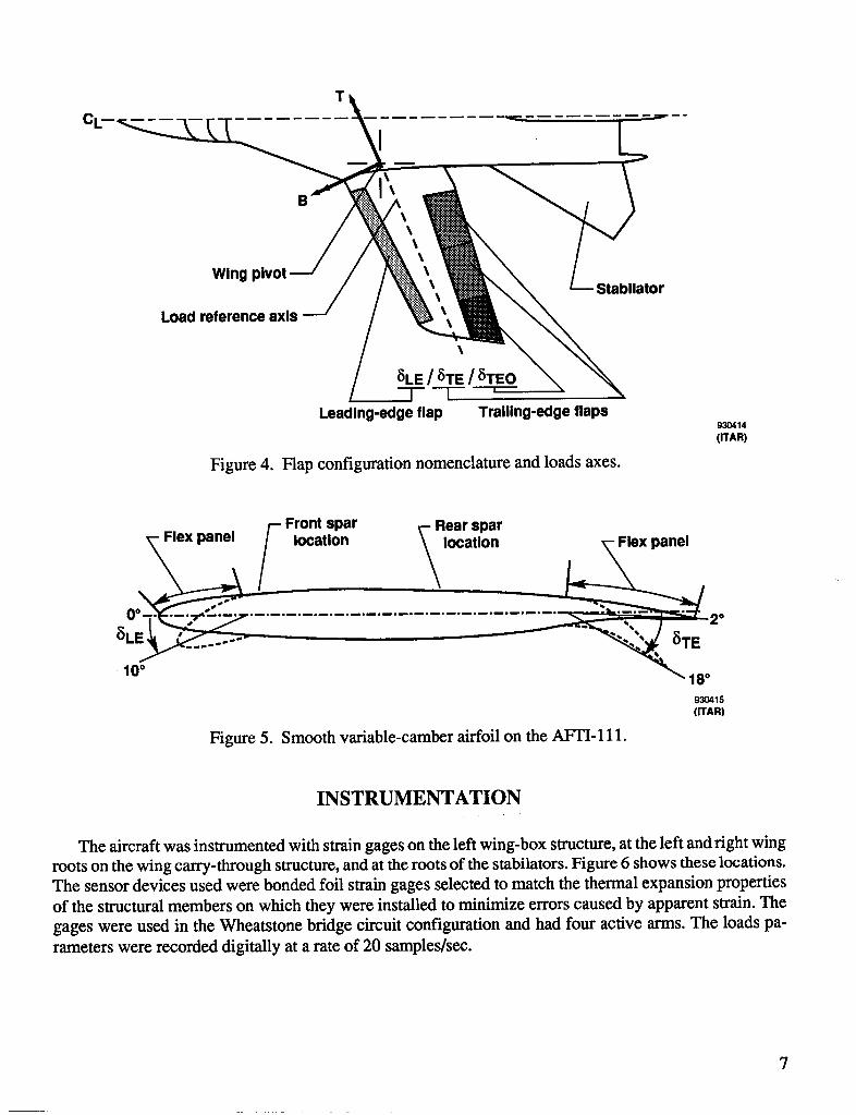
Figure 4. Flap configuration nomenclature and loads axes.
Front spar _- Rear spar
0°- Flsxpansl location _locatlon_.2.
8LE _ _TE10° 18°930415(ITAR)
Figure 5. Smooth variable-camber airfoil on the AFTI-111.
INSTRUMENTATION
The aircraft was instrumented with strain gages on the left wing-box structure, at the left and fight wing
roots on the wing carry-through structure, and at the roots of the stabilators. Figure 6 shows these locations.The sensor devices used were bonded foil strain gages selected to match the thermal expansion properties
of the structural members on which they were installed to minimize errors caused by apparent strain. The
gages were used in the Wheatstone bridge circuit configuration and had four active arms. The loads pa-
rameters were recorded digitally at a rate of 20 samples/see.
7
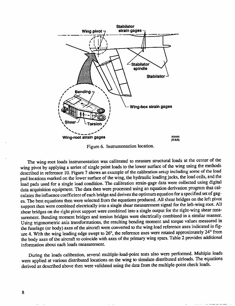
StabilatorWingpivot"7 straingages-j
_;,, t__ Stabilat°r_
_near--, _-Torsion//% /
%
Wing-root strain gages _048s(rrAR)
Figure 6. Instrumentation location.
The wing-root loads instrumentation was calibrated to measure structural loads at the center of thewing pivot by applying a series of single point loads to the lower surface of the wing using the methodsdescribed in reference 10. Figure 7 shows an example of the calibration setup including some of the loadpad locations marked on the lower surface of the wing, the hydraulic loading jacks, the load cells, and theload pads used for a single load condition. The calibration strain-gage data were collected using digitaldata acquisition equipment. The data then were processed using an equation derivation program that cal-culates the influence coefficient of each bridge and derives the optimum equation for a specified set of gag-
es. The best equations then were selected from the equations produced. All shear bridges on the left pivotsupport then were combined electrically into a single shear measurement signal for the left-wing root. Allshear bridges on the right pivot support were combined into a single output for the right-wing shear mea-surement. Bending moment bridges and torsion bridges were electrically combined in a similar manner.Using trigonometric axis transformations, the resulting bending moment and torque values measured inthe fuselage (or body) axes of the aircraft were converted to the wing load reference axes indicated in fig-ure 4. With the wing leading edge swept to 26°, the reference axes were rotated approximately 24° fromthe body axes of the aircraft to coincide with axes of the primary wing spars. Table 2 provides additionalinformation about each loads measurement.
During the loads calibration, several multiple-load-point tests also were performed. Multiple loadswere applied at various distributed locations on the wing to simulate distributed airloads. The equationsderived as described above then were validated using the data from the multiple-point check loads.
8
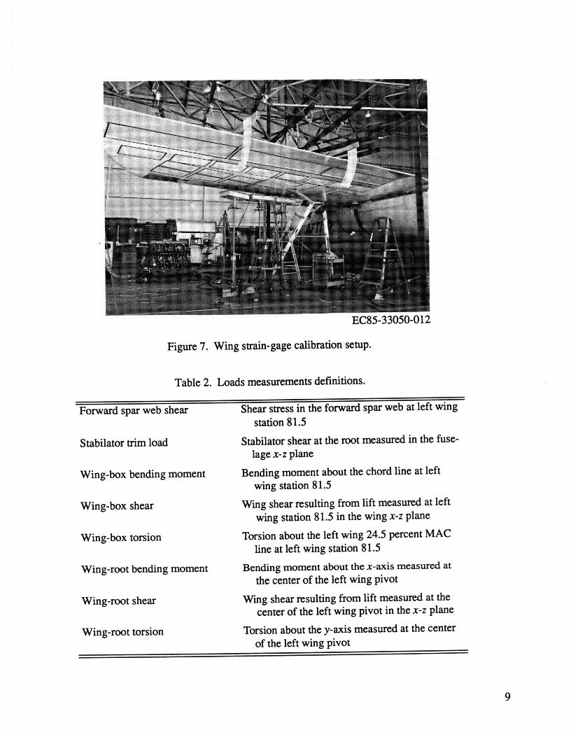
EC85-33050-012
Figure7.Wingstrain-gagecalibrationsetup.
Table 2. Loads measurementsdefinitions.
Forwardspar web shear Shearstress in the forward spar web atleft wingstation81.5
Stabilatortrimload Stabilatorshear at theroot measuredin the fuse-lag€x-z plane
Wing-box bending moment Bending momentabout the chordline at leftwingstation81.5
Wing-boxshear W'mgshearresultingfromliftmeasuredatleftwingstation81.5inthewingx-zplane
Wing-boxtorsion Torsionabouttheleftwing24.5percentMAClineatleftwingstation81.5
Wing-rootbendingmoment Bendingmomentaboutthex-axismeasuredatthecenteroftheleftwingpivot
Wing-rootshear W'mgshearresultingfromliftmeasuredatthecenteroftheleftwingpivotinthex-zplane
Wing-roottorsion Torsionaboutthey-axismeasuredatthecenteroftheleftwingpivot
9
The wing-box strain gages were distributed along a left wingspan station located 81.5-in. outboardfrom the center of the left-wing pivot. This location was chosen as a convenient structural location thatwas far enough outboard from the pivot to monitor the loads in the individual spars. These gages were po-sitioned on the various spars, the upper and lower wing skins, and the various spar webs. The outputs ofthe wing-box strain-gage bridges were recorded individually instead of being combined electrically as thewing-root gages were. Loads equations were derived in the same manner as for the wing-root gages. Theseindividual signals were then combined mathematically using these loads equations to produce values forwing-box shear, bending moment, and torsion. No wing-box measurements were made on the fight wing.
The stabilator strain gages were installed on and near the pivot spindle at the root of both the left andthe fight stabilator. These gages were calibrated and the loads equations were derived in the same manneras for the wing instrumentation. The gage output signals were recorded separately and combined mathe-matically to compute the resultant shear, bending moment, and torsion values as in the case of the wingbox.
FLIGHT TEST CONDITIONS
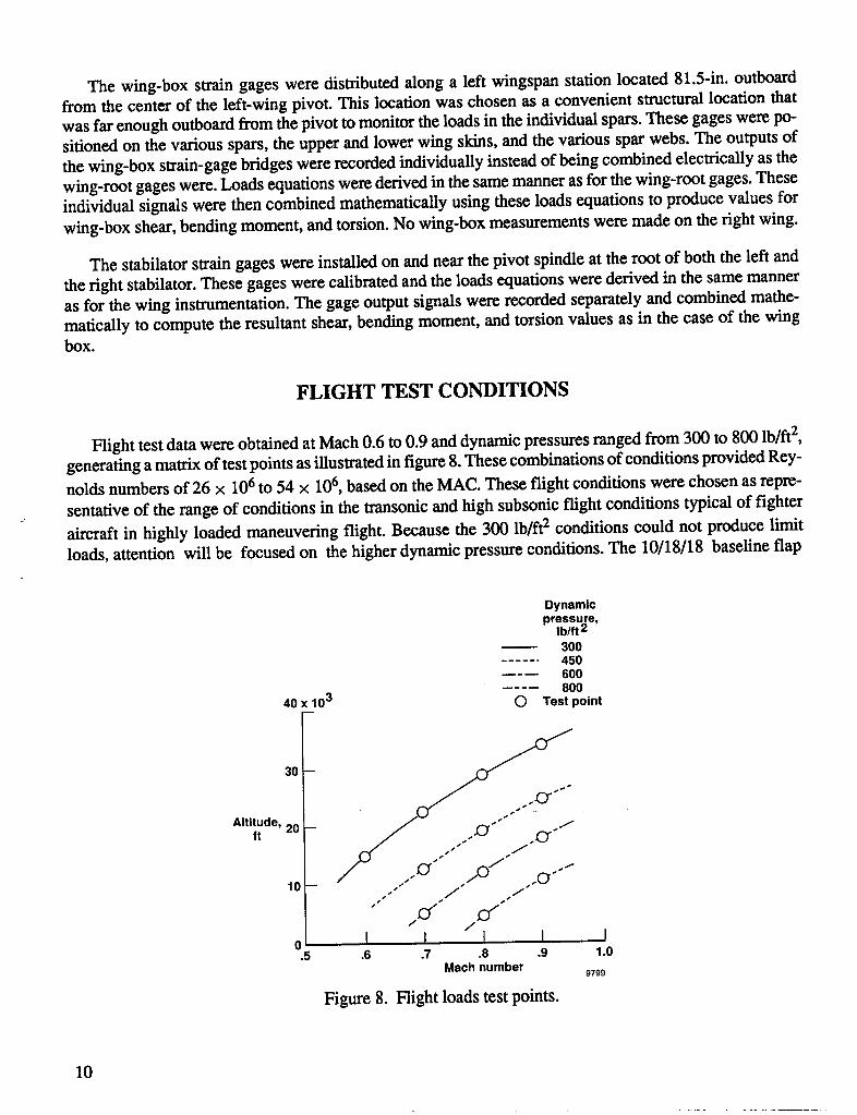
Flight test data were obtained at Mach 0.6 to 0.9 and dynamic pressures ranged from 300 to 800 lb/ft2,generating a matrix of test points as illustrated in figure 8. These combinations of conditions provided Rey-nolds numbers of 26 x 106 to 54 × 106, based on the MAC. These flight conditions were chosen as repre-
sentative of the range of conditions in the transonic and high subsonic flight conditions typical of fighter
aircraft in highly loaded maneuvering flight. Because the 300 lb/ft2 conditions could not produce limitloads, attention will be focused on the higher dynamic pressure conditions. The 10/18/18 baseline flap
Dynamicpressure,
Ib/ft 2300
...... 4506O08OO
40 x 103 C) Test point
30--
Altitude, 20 -- "//" .... -ft
,o- .J" .f .-°""/
o I I I I I.5 .6 .7 .8 .9 1.0
Mach number 9799
Figure 8. Flight loads test points.
10
configuration was flown only at 300 lb/ft2 because of the very high drag produced. The 5/10/10 baselineflap configurations were flown at all test points. The flight test maneuvers used to gather these data werewind-up turns flown at constant Mach number and dynamic pressure in sets of three or more maneuvers,one at each of several specified flap settings. The maneuvers were flown in sets of three or more to mini-mize the change in fuel weight between flap configurations at a given set of flight conditions and thus fa-cilitate comparisons among the measured loads. Maneuvers were rejected and repeated for which theMach number deviated from the target value by more than _+0.02or for which dynamic pressure deviated
by more than +10 percent of the target value. The gross weight for these maneuvers was constrained tothe wing maneuver design point of 70,000 lb with a tolerance of +5,000 lb. All maneuvers were flown ata leading-edge wing sweep of 26°.
As mentioned earlier, the nominal undeflected position of the flaps corresponds to a flap configurationof 0/2/2. The 5/10/10 flap setting was chosen as the baseline for configurations having moderate camberand as the basis of comparison for the partial and full MLC configurations. The 5/10/4 is an intermediatedeflection, approximately halfway between the baseline and the full up position of the outboard flap seg-ment. The 5/10/-1 setting is equivalent to the fully deployed MLC configuration, given the 5/10/10 man-ually set baseline. The 10/18/18 flap combination was chosen as the other baseline and corresponds to ahigh-camber configuration.
To evaluate the effect of a change in leading-edge deflection with the same baseline wailing-edge de-flection, a flap setting of 10/10/10 was flown at 300 lb/ft2 at three of the Mach numbers. These data enabledan estimate to be made of the relative contributions of the leading and trailing edges to the changes ob-served at the second baseline configuration, 10/18/18. Because the 5/10/10 and 10/18/18 settings wereavailable among the discrete choices in the MAW control system, they were easily duplicated from onemaneuver to another, thus substantially improving repeatability in the data. Flight conditions were selectedto use the majority of the cleared subsonic envelope of the airplane.
Since this airplane also uses differential stabilator deflections (rolling tail) for roll control, the originalplan was to fly the MLC maneuvers using fixed flaperons and rolling tail only for roll control to eliminatethe effects of roll-control loads from the wing data. An evaluation of the two methods was made by flyingone maneuver with flaperons fixed and one maneuver with flaperons active at the same conditions. Spec-ified conditions of Mach and dynamic pressure were found to be more difficult to maintain in themaneuvers with the reduction in roll-control authority, particularly at the lower dynamic pressures. Theadditional time and _ght cost of setting up the configuration to fly the test points with flaperons fixed didnot justify the benefits (which proved to be slight) in the data collected. Therefore, all loads data presentedwere collected with the roll commands active on the flaperons.
RESULTS AND DISCUSSION
Although flight loads data were acquired at all of the Mach and dynamic pressure conditions indicatedin figure 8, the loads data presented in this report in graphic form will consist of only those data needed tocharacterize and summarize the effects of maneuver load control on the airplane component loads. The
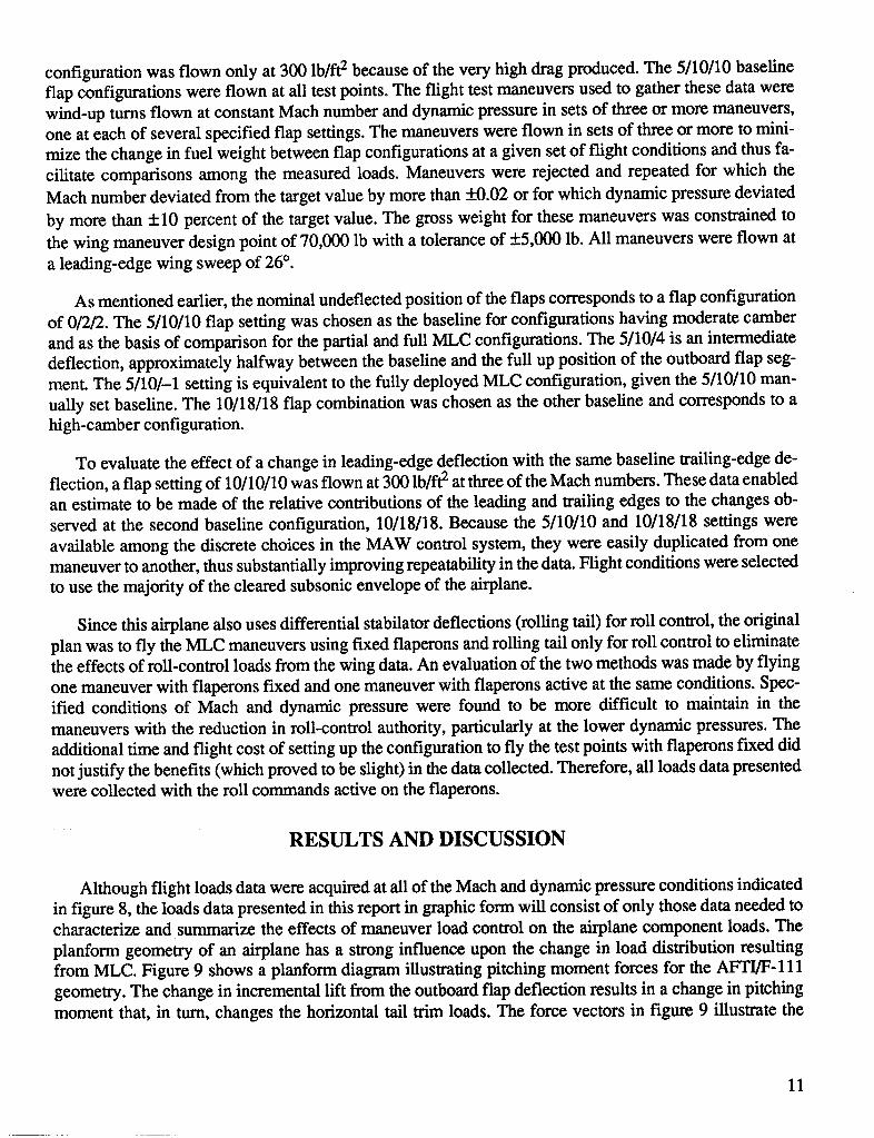
planform geometry of an airplane has a strong influence upon the change in load distribution resultingfrom MLC. Figure 9 shows a planform diagram illustrating pitching moment forces for the AFTI/F-111geometry. The change in incremental lift from the outboard flap deflection results in a change in pitchingmoment that, in turn, changes the horizontal tail trim loads. The force vectors in figure 9 illustrate the
11
V
beneficial effect occurring with MLC. The aft-swept wing places incremental outboard flap loads far aftof the e.g. Therefore, raising the outboard flap segment eliminates the incremental pitching moment gen-erated by the outboard trailing-edge flap, thereby reducing the trim load requirement as compared with thebaseline configuration. This trim load reduction is significant as will be seen in the discussion of the flightdata.
I
Bsseline Lift_._. !i
5110110
Nzw 1 Pitch .m.load.
Outboardtrad,ng edge
confiauration Lift Incremental loadMLCY
,10,-1 1 tNzw Pitch trim load
930416(ITAR)
Figure 9. Forces and moments in the vertical plane at a given flight condition and center of gravity (air-craft shown in planform view for clarity).
Wing-Root Loads
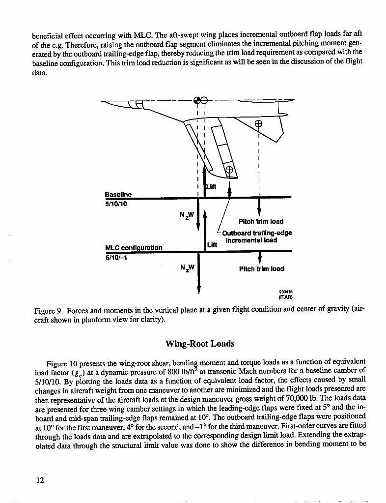
Figure 10 presents the wing-root shear, bendin_ moment and torque loads as a function of equivalentload factor (ge) at a dynamic pressure of 800 lb/fP at transonic Mach numbers for a baseline camber of5/10/10. By plotting the loads data as a function of equivalent load factor, the effects caused by smallchanges in aircraft weight from one maneuver to another are minimized and the flight loads presented arethen representative of the aircraft loads at the design maneuver gross weight of 70,000 lb. The loads dataare presented for three wing camber settings in which the leading-edge flaps were fixed at 5° and the in-board and mid-span trailing-edge flaps remained at 10°. The outboard trailing-edge flaps were positionedat 10° for the frost maneuver, 4° for the second, and-1 ° for the third maneuver. First-order curves are fitted
through the loads data and are extrapolated to the corresponding design limit load. Extending the extrap-olated data through the structural limit value was done to show the difference in bending moment to be
12
expected at the structural limit with the MLC configuration. Other structural limits or severe buffet, how-ever, may preclude reaching that point at some flight conditions. Other figures showing extrapolated data
should be interpreted similarly.
160 x 103
Structural limit
120--............................... _7--First-order curve fit ._'/_"
100- and extrapolation-_ _._""
Flight data__,_ / setting60 - .,_F _ o - ---- 5/10/10
,, _ A ...... 5/10/4
_,_" M= 0.8
20_.f __--80-o,b/.2_" I I I I I I I
0 1 2 3 4 5 6 7
Load factor, ge _oo4_7([TAR)
(a) Shear load.
R16 x 10- Structural limit
First-order curve fit
14- and extrapolation-_ _./,,'_,//"
soss _°_S° SS'_S S"
10 - Flight data-_
moment, 8in-lb
4/.....-.t •..... ,10,_1.,.,-r
2 "/ M = 0.8" _ = 800 Ib/ft2
I I I I I I I0 1 2 3 4 5 6 7
Load factor, ge .zo._8([TAR)
(b) Bending moment.
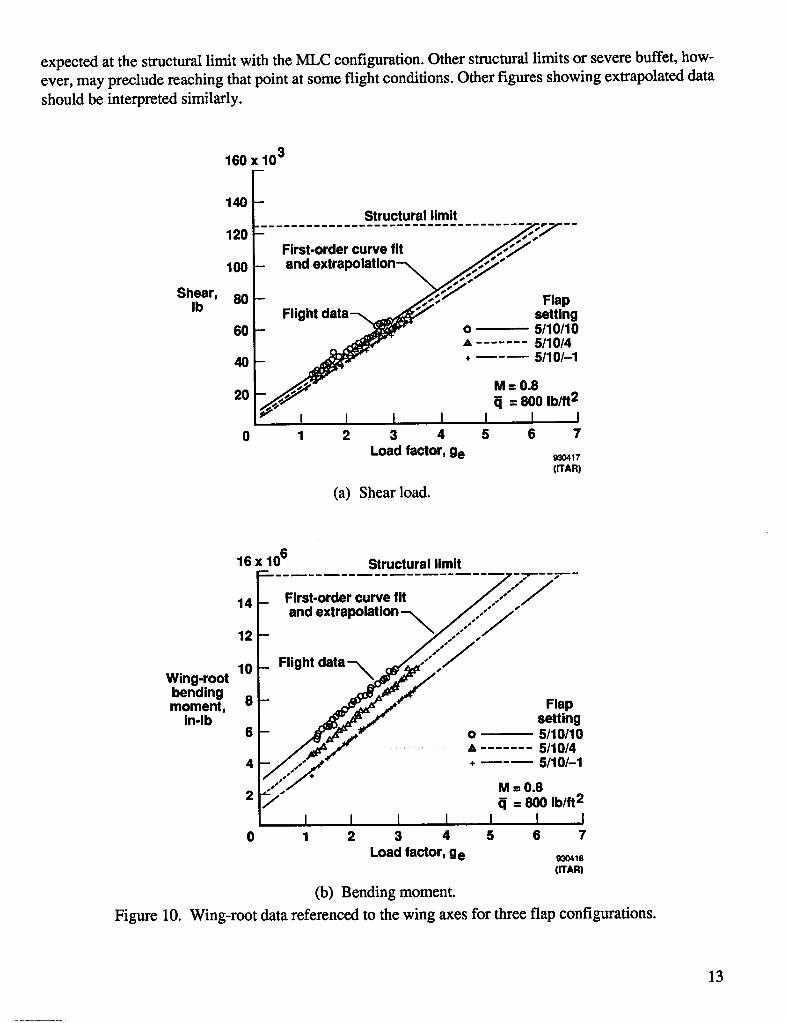
Figure 10. Wing-root data referenced to the wing axes for three flap configurations.
13
.......... r
-1 x 10⁶
First-order curve fit
and ___,_-_
extrapolation
Flight data-2 - , -,_. "_
.....
Wing-root _____o Flap
-- settingtorsion, -3 - 5/10/10
In-lb A 5/10/4+ 5/10/-1
-4 -
Structural limit M - 0.8_[ = 800 Ib/ft2
I I I I t I I0 1 2 3 4 5 6 7
Load factor, ge _,3o4._9(rrAR)
(c) Torsion (Mach 0.8).
-1 x 10⁶
i Flap
settingFirst-order curve fit o 5/10/10and extrapolation-_ * ....... 5/10/4
-2 _ +----- 5/10/-1
Wing-root L :_.............. "'-'-"-
in-lb FI
-4 _- Structural limit M = 0.9
/ = 800 Ib/ft2
-5 I I I I I I I0 1 2 3 4 5 6 7
Load factor, ge 9ao420(ITAR)
(d) Torsion (Mach 0.9).
Figure 10. Concluded.
14
The data in figure 10(a) show that a small reduction in the wing-root shear load was achieved by raisingthe outboard trailing-edge flap. This small reduction in shear load is principally attributed to the corre-sponding reduction in the pitch trim load, which will be shown in a later figure.
Perhaps the most important issue in an effort to reduce the wing loads through automatic schedulingof wing control surfaces is a desire to reduce the wing-root bending moment at a given load factor. For theAFFI/F- 111, the wing-root bending moment represents the most critical loading parameter of the wingpivot structure. Figure 10(b) shows the effect of changing the position of the outboard trailing-edge flap
segment on root bending moment. The extrapolated data out to the structural limit of 15.5 × 10⁶ in-lbshows that an additional 1 g is available by raising the outboard trailing-edge flap segment up from 10° to--10,
The shear and bending moment data shown for M = 0.8 in figures 10(a) and 10(b) are representativeof the data at the other Mach numbers investigated. The wing-root torsion data (figs. 10(c) and 10(d)),however, display different trends with increasing load factor depending on Mach number. This differenceresults from the location of the load reference axis and the fact that the center of pressure on the wing
moves aft with increasing Mach number at a given angle of attack (ref. 11). Figure 10(c) shows that atM = 0.8 the wing-root torsion decreases with both increasing load factor and the raising of the outboardtrailing-edge flap. For this Mach number both variables have the effect of moving the torsional load awayfrom the negative limit load toward zero load. The positive limit load is 2.54 × 10⁶ in-lb (off the graph).At M = 0.9 (figure 10(d)), however, the center of pressure has moved aft of the load reference axis (fig. 3),which causes the torsional load to increase with increasing load factor. Thus, for the M = 0.9 condition,deflecting the outboard trailing-edge flap segment up alleviates the load which is approaching the struc-tural limit as opposed to the Math 0.8 case where the torsion load is moving away from the structural limitwith increasing load factor.
The data of figure 10 shows that the wing-root bending moment, which is the most critical load param-eter for these conditions on the AFTI/F-111 aircraft, reaches its limit value at a lower load factor than thatfor either the shear or torsional loads. The shear load is the next most critical load parameter. Although thetorsional load at the wing root has a large sensitivity to change in Mach number, a limit load value is neverapproached and is not a significant factor in implementing MLC in the AFTI/F- 111 aircraft.
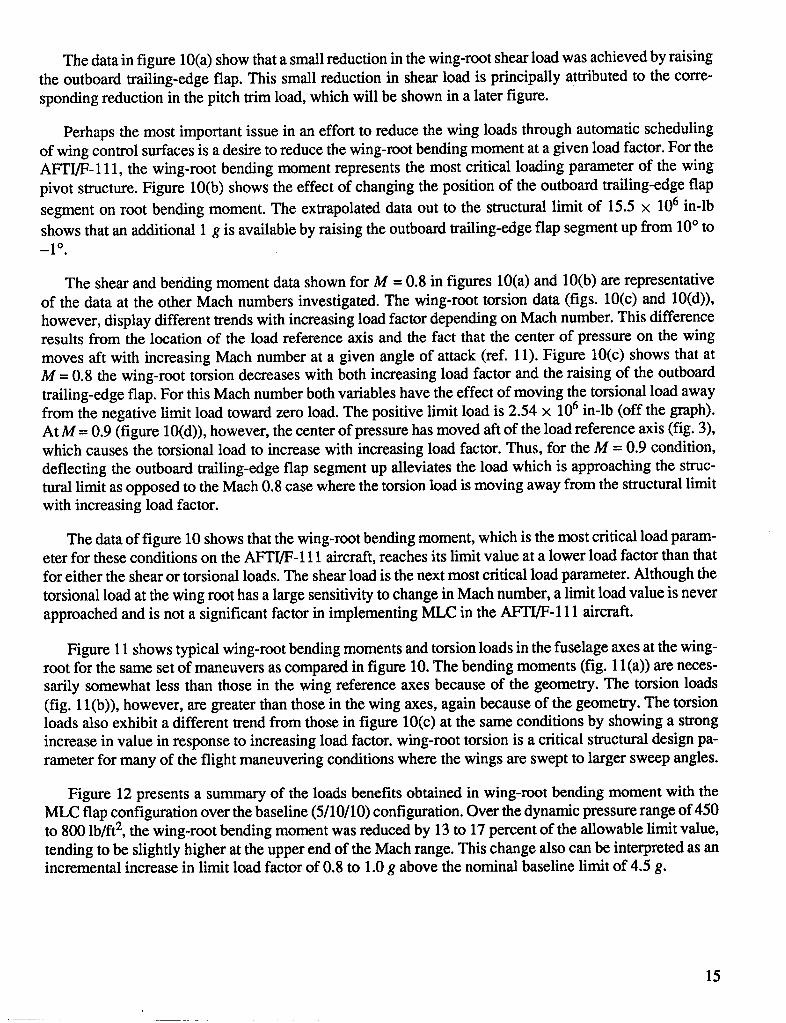
Figure 11 shows typical wing-root bending moments and torsion loads in the fuselage axes at the wing-root for the same set of maneuvers as compared in figure 10. The bending moments (fig. 1l(a)) are neces-sarily somewhat less than those in the wing reference axes because of the geometry. The torsion loads(fig. 11(b)), however, are greater than those in the wing axes, again because of the geometry. The torsionloads also exhibit a different trend from those in figure 10(c) at the same conditions by showing a strongincrease in value in response to increasing load factor, wing-root torsion is a critical structural design pa-rameter for many of the flight maneuvering conditions where the wings are swept to larger sweep angles.
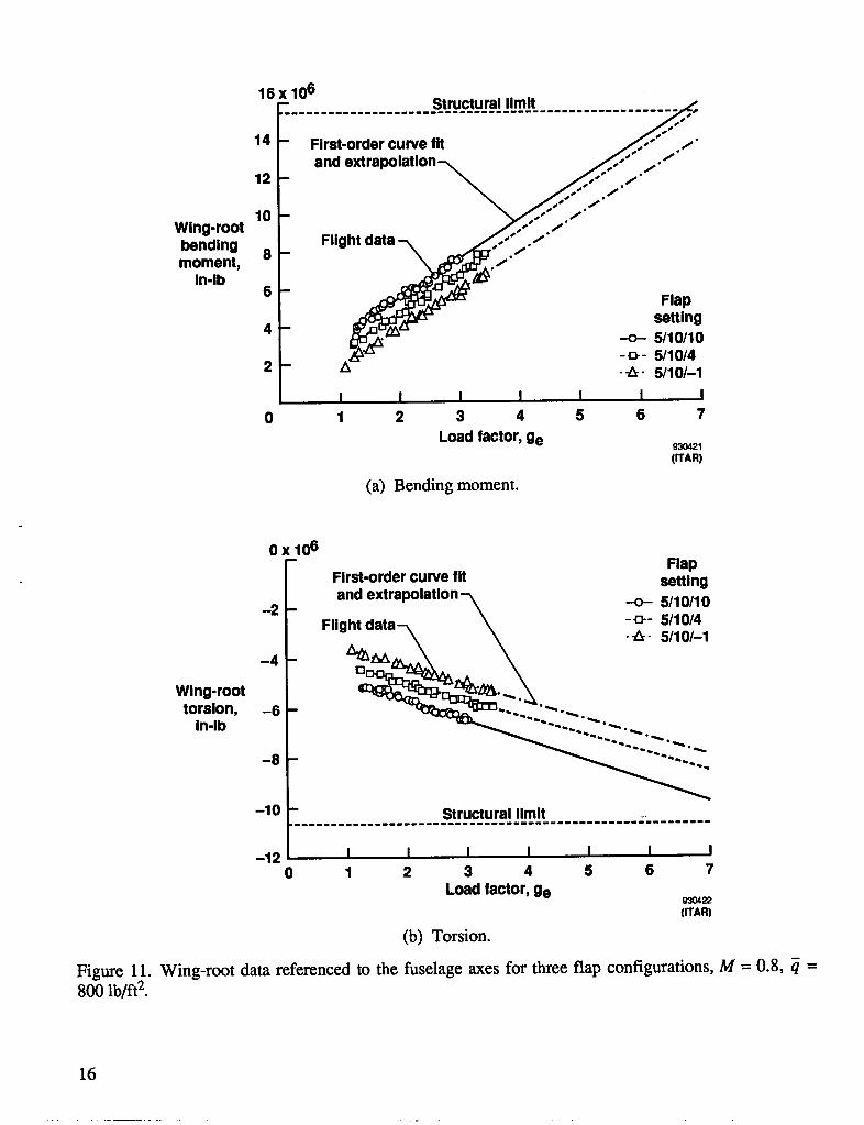
Figure 12 presents a summary of the loads benefits obtained in wing-root bending moment with theMLC flap configuration over the baseline (5/10/10) configuration. Over the dynamic pressure range of 450to 800 lb/ft 2, the wing-root bending moment was reduced by 13 to 17 percent of the allowable limit value,tending to be slightly higher at the upper end of the Mach range. This change also can be interpreted as anincremental increase in limit load factor of 0.8 to 1.0 g above the nominal baseline limit of 4.5 g.
15
r
16 X 106- ................... .s..w.c.tu.r.a!!Lm...................
oS 'F°.j::14 - First-order curve fit
and extrapolation-_ ,._,,,-'" ./"/"12 - _ j_...-" .,./"
10 - "_..-" ,/j..- /
Wing-root _ Flight data ..-'/./"moment, 8 _./.
In-lb 6Flap
_ _ setting4 _._.._ -o- 5/10/10
-_- 5/10/42- L_ -4- 5/10/-1
I I I I I I I0 1 2 3 4 5 6 7
Load factor, ge 93042_(ITAR)
(a) Bending moment.
0 x 106- Flap
First-order curve fit setting
-2 - and extrapolatlon-\-- -o- 5/10/10
Flight data--_ _ -_-5//110//.41-4 - _'_ " " -
Wing-roottorsion, -6 - " " " " •
In-lb
--8 --
-10 - Structural limit
-12 I I I I I I I0 1 2 3 4 5 6 7
Load factor, ge 93O422(ITAR)
(b) Torsion.
Figure 11. Wing-root data referenced to the fuselage axes for three flap configurations, M = 0.8, q =800 lb/ft 2.
16
20--q : 450to 800 Ib/ft2
MLCbendingmomentreduction,15 --
percentlimit
1o I I I I.6 .7 .8 .9 1.0
Machnumber _oso6(ITAR)
(a) Range of bending moment reduction at constant equivalent load factor (ge)"
!___. Limitwith MLC
Maximumallowable t/ / / / / / / / •loadfactor, Baselinelimit
ge I I I I.6 .7 .8 .9 1.0
Machnumber _o4_(ITAR)
(b) Range of maximum allowable load factor with MLC compared with the baseline design limit load fac-tor using uniform flap settings. Limits for this figure are determined by the maximum allowable wing-rootbending moment.
Figure 12. Structural and performance benefits produced with MLC for a range of flight test conditionsfor M = 0.7 to 0.9.
Wing-Box Loads
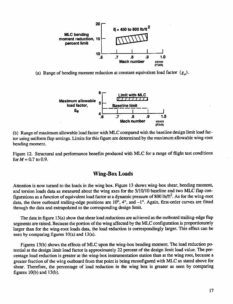
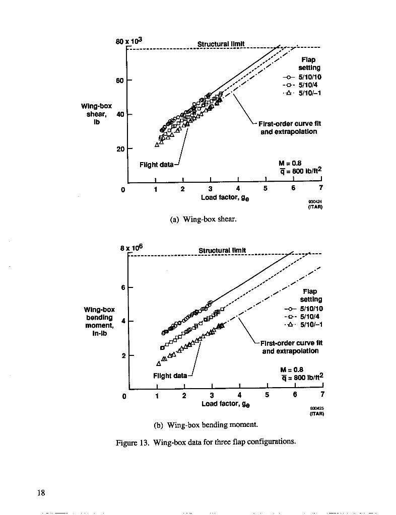
Attention is now turned to the loads in the wing box. Figure 13 shows wing-box shear, bending moment,and torsion loads data as measured about the wing axes for the 5/10/10 baseline and two MLC flap con-figurations as a function of equivalent load factor at a dynamic pressure of 800 lb/ft 2. As for the wing-rootdata, the three outboard trailing-edge positions are 10°, 4°, and -1 °. Again, In'st-order curves are fittedthrough the data and extrapolated to the corresponding design limit.
The data in figure 13(a) show that shear load reductions are achieved as the outboard trailing-edge flapsegments are raised. Because the portion of the wing affected by the MLC configuration is proportionatelylarger than for the wing-root loads data, the load reduction is correspondingly larger. This effect can beseen by comparing figures 10(a) and 13(a).
Figures 13(b) shows the effects of MLC upon the wing-box bending moment. The load reduction po-tential at the design limit load factor is approximately 22 percent of the design limit load value. The per-centage load reduction is greater at the wing-box instrumentation station than at the wing root, because agreater fraction of the wing outboard from that point is being reconfigured with MLC as stated above forshear. Therefore, the percentage of load reduction in the wing box is greater as seen by comparingfigures 10(b) and 13(b).
17
80 x 103 Structural limit
......... •I_.";: 1' Flap
_.-_,./" setting._...:'.- -o-5110110
80- .,_...:;:-" _ 5/lO/4
Wing-box _ __r_-,_ -T " _ First-order curve fit
shear, 40Ib
20 - Fiigh__at_a__ and extrapolationM =0.8= 800 Ib/ft2
I I I I I I I0 1 2 3 4 5 6 7
Load factor, ge o30424(ITAR)
(a) Wing-box shear.
8 x 10⁶ Structural limit.- ............................................... _;,----
' "_o S
s °
J oos_ _ ._
6 - _ ..-'" 1"I Flap
J....-"..i" settingWlng-box _ .,._'" ./" -o- 5/10/10
_ ,.," _ 511014
bendlng 4 - " __ d_r'ci_l_imoment, __.__
In-lb
F_:h:i:/ First'°i__°._t,_ I
2 - and e
2
I I I I I I I0 1 2 3 4 5 6 7
Load factor, ge 8_o425(ITAR)
(b) Wing-box bending moment.
Figure 13. Wing-box data for three flap configurations.
18
0 x 106- Flap
First-order curve fit setting
and extmpolatlon-_ -o- 5/10/10\ - _- 5/10/4
-1 - FIIgM data-_ _ -_- 5110/-1
Wlng-box _""''" "" _ .......... ""torsion, -2 - L_L _- ............In-lb D_E_I_
M=0.8-3 - _ = 800 Ib/ft2
Structural limit
-4 I I I I I I I0 1 2 3 4 5 6 7
Load factor, ge 93o426(WAR)
(c) Wing-box torsion (Mach 0.8).
Ox 106- Flap
First-order curve fit settingand extrapolation -o- 5/10/10
- _- 5/10/4
-1 - Flight data-_ -_- 5/10/-1M:0.9
Wing-box _._ _ = 800 Ib/ft2torsion, -2 -In-lb .....
........--3 --
• ,. Structural limit
-4 I I I I I I I0 1 2 3 4 5 6 7
Load factor, ge 93O427(WAR)
(d) Wing-box torsion (Mach 0.9).
Figure 13. Concluded.
19
I
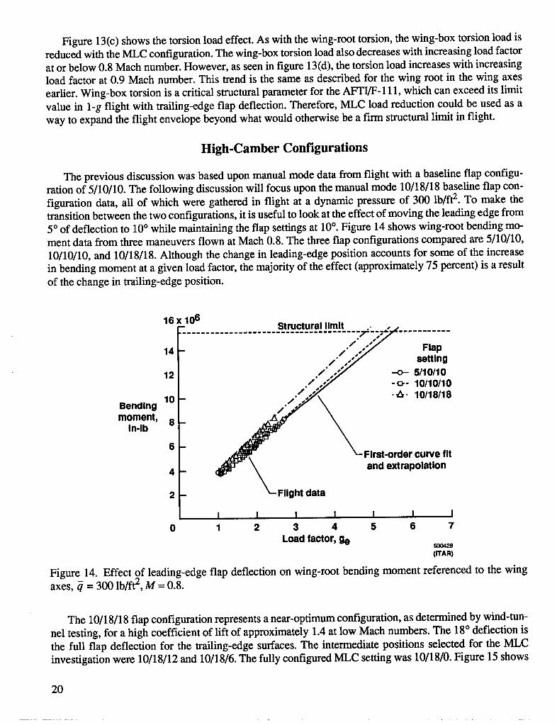
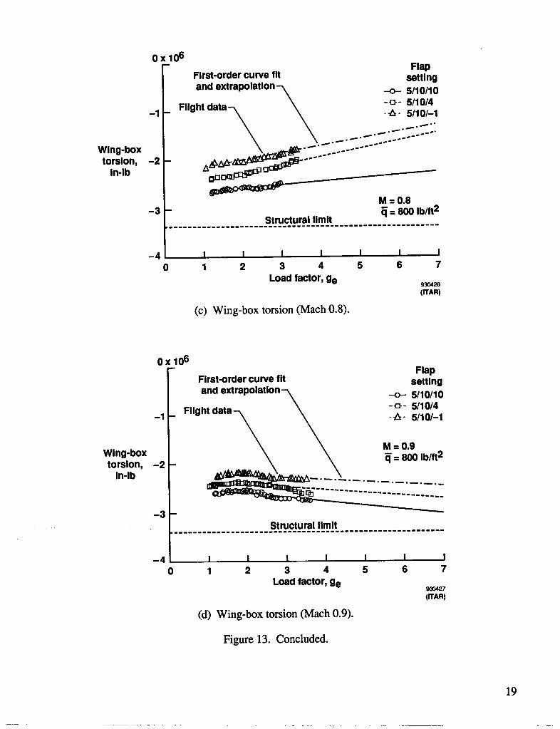
Figure 13(c) shows the torsion load effect. As with the wing-root torsion, the wing-box torsion load isreduced with the MLC configuration. The wing-box torsion load also decreases with increasing load factorat or below 0.8 Mach number. However, as seen in figure 13(d), the torsion load increases with increasingload factor at 0.9 Mach number. This trend is the same as described for the wing root in the wing axesearlier. Wing-box torsion is a critical structural parameter for the AFFI/F- 111, which can exceed its limitvalue in 1-g flight with trailing-edge flap deflection. Therefore, MLC load reduction could be used as away to expand the flight envelope beyond what would otherwise be a firm structural limit in flight.
High-Camber Configurations
The previous discussion was based upon manual mode data from flight with a baseline flap configu-ration of 5/10/10. The following discussion will focus upon the manual mode 10/18/18 baseline flap con-figuration data, all of which were gathered in flight at a dynamic pressure of 300 lb/ft2. To make thetransition between the two configurations, it is useful to look at the effect of moving the leading edge from5 ° of deflection to 10° while maintaining the flap settings at 10°. Figure 14 shows wing-root bending mo-ment data from three maneuvers flown at Mach 0.8. The three flap configurations compared are 5/10/10,10/10/10, and 10/18/18. Although the change in leading-edge position accounts for some of the increasein bending moment at a given load factor, the majority of the effect (approximately 75 percent) is a resultof the change in trailing-edge position.
16x10 6 Structural limit
14 - //..'7" Flap/ /_/" _tting
12 /" .-_ -o- 5/10/10--10110110
Bending 10! /jf_ -_-10/18/18
moment, 8in-lb
6_ _-First-ordercurvefit
4 - _ _ andextrapolationFlightdata2
I I I I I I I0 1 2 3 4 5 6 7
Loadfactor,ge _o_8(ITAR)
Figure 14. Effect of leading-edge flap deflection on wing-root bending moment referenced to the wingaxes, _ = 300 lb/ft 2, M = 0.8.
The 10/18/18 flap configuration represents a near-optimum configuration, as determined by wind-tun-nel testing, for a high coefficient of lift of approximately 1.4 at low Mach numbers. The 18° deflection isthe full flap deflection for the trailing-edge surfaces. The intermediate positions selected for the MLCinvestigation were 10/18/12 and 10/18/6. The fully configured MLC setting was 10/18/0. Figure 15 shows
20
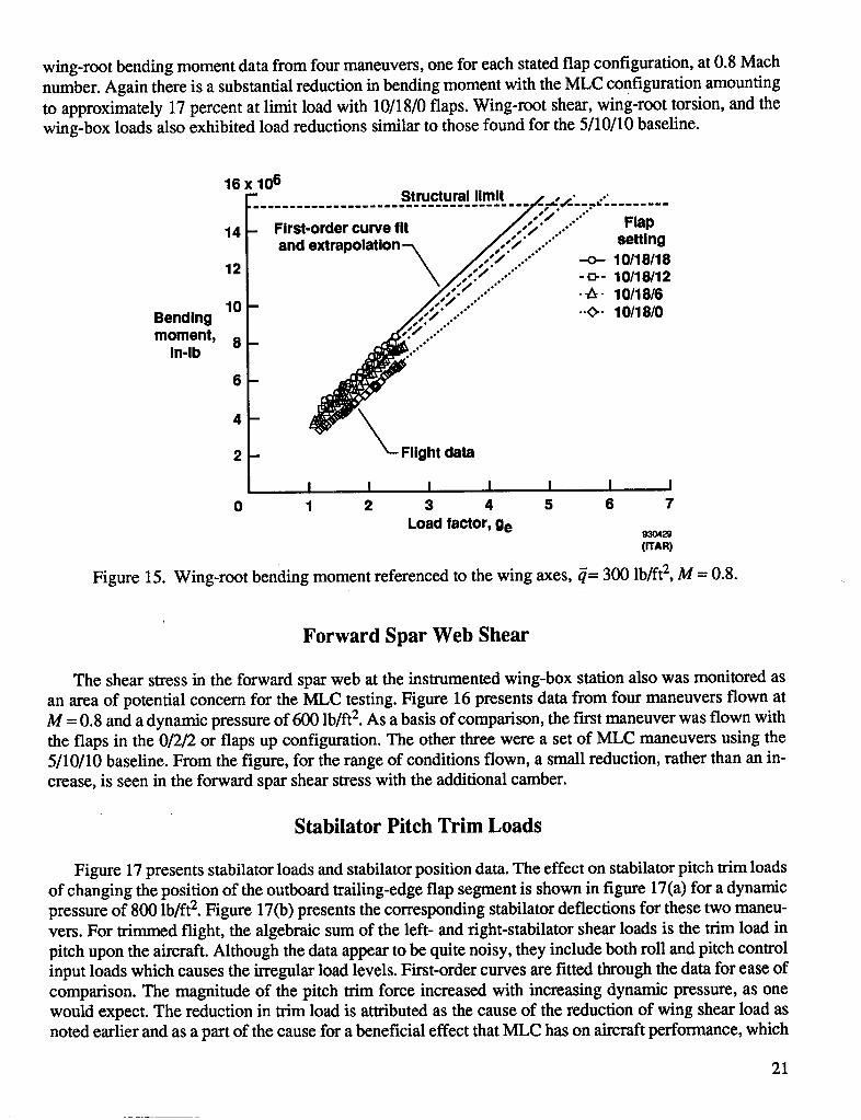
wing-root bending moment data from four maneuvers, one for each stated flap configuration, at 0.8 Machnumber. Again there is a substantial reduction in bending moment with the MLC configuration amountingto approximately 17 percent at limit load with 10/18/0 flaps. Wing-root shear, wing-root torsion, and thewing-box loads also exhibited load reductions similar to those found for the 5/10/10 baseline.
16 x 106- Structuralllmlt ,, , ,. •......................................... f-.-,,-4---:...........
OS •"
14 - First-ordercurvefit 7/7/: ..'" FlapS • o+"
// , settingandextrapolation--k ,/_'/:_'" ...'"\___ ....'" -o- 10/18/1812-,,,.\/',-':'....'"-o-lO,m2Y/; :/...."" lO/18/6
Bending 10- ,_,,_:./....""" -.<>-lo/1e/o
moment,ln.lb6-8! J!./..i.'"""4
2-
I I I I I I I0 1 2 3 4 5 6 7
Loadfactor,ge 9304,,(ITAR)
Figure 15. Wing-root bending moment referenced to the wing axes, _= 300 lb/ft 2, M = 0.8.
Forward Spar Web Shear
The shear stress in the forward spar web at the instrumented wing-box station also was monitored asan area of potential concern for the MLC testing. Figure 16 presents data from four maneuvers flown atM = 0.8 and a dynamic pressure of 600 Ib/ft 2. As a basis of comparison, the fast maneuver was flown withthe flaps in the 0/2/2 or flaps up configuration. The other three were a set of MLC maneuvers using the5/10/10 baseline. From the figure, for the range of conditions flown, a small reduction, rather than an in-crease, is seen in the forward spar shear stress with the additional camber.
Stabilator Pitch Trim Loads
Figure 17 presents stabilator loads and stabilator position data. The effect on stabilator pitch trim loadsof changing the position of the outboard trailing-edge flap segment is shown in figure 17(a) for a dynamicpressure of 800 lb/ft2. Figure 17(b) presents the corresponding stabilator deflections for these two maneu-vers. For trimmed flight, the algebraic sum of the left- and right-stabilator shear loads is the trim load inpitch upon the aircraft. Although the data appear to be quite noisy, they include both roll and pitch controlinput loads which causes the irregular load levels. First-order curves are fitted through the data for ease ofcomparison. The magnitude of the pitch trim force increased with increasing dynamic pressure, as onewould expect. The reduction in trim load is attributed as the cause of the reduction of wing shear load asnoted earlier and as a part of the cause for a beneficial effect that MLC has on aircraft performance, which
21
.... i ,
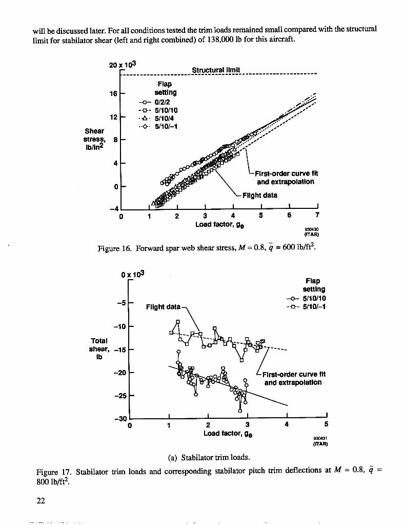
will be discussed later. For all conditions tested the trim loads remained small compared with the structural
limit for stabilator shear (left and right combined) of 138,000 lb for this aircraft.
20x 03- Structural llmlt
Flap16 settlng ..5
-o-- 012/2 _-_- 5110110 ../i_.."-
12 - -_- 5/10/4 _,_,,'"
.." .-'"
Shear _iiii
stress, 8 - / ""ib/in2 ,-'"
4-
- r curve fit
o- ..d_d_- N and extrap<)lationFlight data
-_ I I I I I I I0 1 2 3 4 5 6 7
Load factor, ge _o4so(ITAR)
Figure 16. Forward spar web shear stress, M = 0.8, q = 600 lb/ft 2.
OxlO3- Flap
setting-o- 5/10/10
-5 - Fllght data -_- 5/10/-I
-10 - -_
Total
shear, -15 - - ....Ib
- en,.-25 -
-30 I I I I I0 1 2 3 4 5
Load factor, ge _(WAR)
(a) Stabilator trim loads.
Figure 17. Stabilator trim loads and corresponding stabilator pitch trim deflections at M = 0.8, _ =800 lb/ft 2.
22
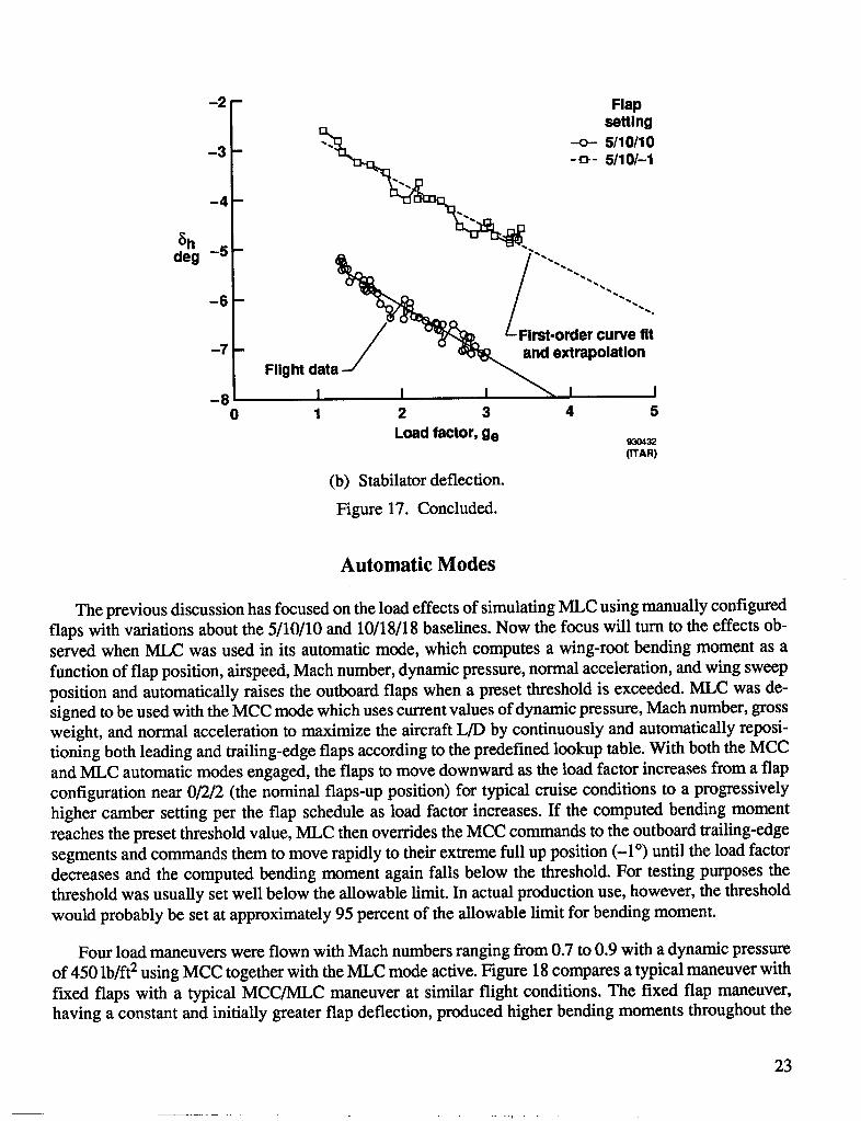
-2 - FlapsettingEL
-3 - "'_ --o- 5/10/10
-_'-. D -a-- 5/10/-1_4
rat-ordercurvefit
-7 FllghtdataJ _d extrapolation-8 I I I _ I I
0 1 2 3 4 5
Loadfactor,ge _o4s2(ITAR)
(b) Stabilator deflection.
Figure 17. Concluded.
Automatic Modes
The previous discussion has focused on the load effects of simulating MLC using manually configuredflaps with variations about the 5/10/10 and 10/18/18 baselines. Now the focus will turn to the effects ob-served when MLC was used in its automatic mode, which computes a wing-root bending moment as a
function of flap position, airspeed, Mach number, dynamic pressure, normal acceleration, and wing sweepposition and automatically raises the outboard flaps when a preset threshold is exceeded. MLC was de-signed to be used with the MCC mode which uses current values of dynamic pressure, Mach number, grossweight, and normal acceleration to maximize the aircraft L/D by continuously and automatically reposi-tioning both leading and trailing-edge flaps according to the predefined lookup table. With both the MCCand MLC automatic modes engaged, the flaps to move downward as the load factor increases from a flapconfiguration near 0/2/2 (the nominal flaps-up position) for typical cruise conditions to a progressivelyhigher camber setting per the flap schedule as load factor increases. If the computed bending momentreaches the preset threshold value, MLC then overrides the MCC commands to the outboard trailing-edgesegments and commands them to move rapidly to their extreme full up position (-1 °) until the load factordecreases and the computed bending moment again falls below the threshold. For testing purposes thethreshold was usually set well below the allowable limit. In actual production use, however, the thresholdwould probably be set at approximately 95 percent of the allowable limit for bending moment.
Four load maneuvers were flown with Mach numbers ranging from 0.7 to 0.9 with a dynamic pressureof 450 lb/ft 2 using MCC together with the MLC mode active. Figure 18 compares a typical maneuver withfixed flaps with a typical MCC/MLC maneuver at similar flight conditions. The fixed flap maneuver,having a constant and initially greater flap deflection, produced higher bending moments throughout the
23
• ' r .......
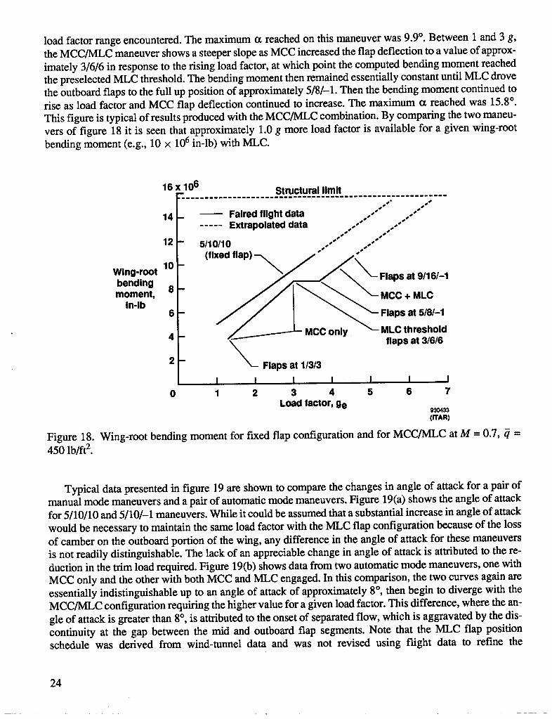
load factor range encountered. The maximum 0t reached on this maneuver was 9.9°. Between 1 and 3 g,the MCC/MLC maneuver shows a steeper slope as MCC increased the flap deflection to a value of approx-imately 3/6/6 in response to the rising load factor, at which point the computed bending moment reachedthe preselected MLC threshold. The bending moment then remained essentially constant until MLC drovethe outboard flaps to the full up position of approximately 5/8/-1. Then the bending moment continued torise as load factor and MCC flap deflection continued to increase. The maximum (z reached was 15.8°.This figure is typical of results produced with the MCC/MLC combination. By comparing the two maneu-vers of figure 18 it is seen that approximately 1.0 g more load factor is available for a given wing-rootbending moment (e.g., 10 × 106 in-lb) with MLC.
16 x 106 Structurallimit
Oos S* SSO °S
14 - Fairedflightdata oo- .o..... Extrapolateddata .o.o" oo.°°
## ##
12 .° oo"5110110 ,, o
""(fixedflap) °
Wing'r°°t 10 ___ _cPS:t:_:
bending /-1moment, 8
In'lb 6 _____ nly__ ;:Pc s at 5'8/-14 Mec o thresholdflapsat 3/6/6\2 - _-- Flapsat 1/3/3
I I I I I I I0 1 2 3 4 5 6 7
Loadfactor,ge 93O433(ITAR)
Figure 18. Wing-root bending moment for fixed flap configuration and for MCC/MLC at M = 0.7, _ =450 lb/ft 2.
Typical data presented in figure 19 are shown to compare the changes in angle of attack for a pair ofmanual mode maneuvers and a pair of automatic mode maneuvers. Figure 19(a) shows the angle of attackfor 5/10/10 and 5/10/-1 maneuvers. While it could be assumed that a substantial increase in angle of attack
would be necessary to maintain the same load factor with the MLC flap configuration because of the lossof camber on the outboard portion of the wing, any difference in the angle of attack for these maneuversis not readily distinguishable. The lack of an appreciable change in angle of attack is attributed to the re-duction in the trim load required. Figure 19(b) shows data from two automatic mode maneuvers, one withMCC only and the other with both MCC and MLC engaged. In this comparison, the two curves again areessentially indistinguishable up to an angle of attack of approximately 8 °, then begin to diverge with theMCC/MLC configuration requiring the higher value for a given load factor. This difference, where the an-gle of attack is greater than 8°, is attributed to the onset of separated flow, which is aggravated by the dis-continuity at the gap between the mid and outboard flap segments. Note that the MLC flap positionschedule was derived from wind-tunnel data and was not revised using flight data to refine the
24
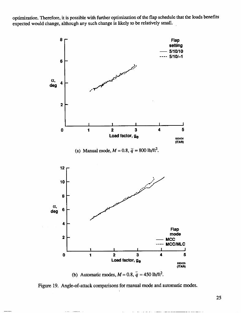
optimization. Therefore, it is possible with further optimization of the flap schedule that the loads benefitsexpected would change, although any such change is likely to be relatively small.
8 - Flapsetting5/10/10
.... 5/10/-16-
(1, f'deg 4-
n
I I I I I0 1 2 3 4 5
Load factor, ge 930434(ITAR)
(a) Manual mode, M = 0.8, q = 800 lb/ft 2.
12-
10 - ,__
8 -
(1,
deg 6-
4-
Flapmode
2 - _ MCC.... MCC/MLC
I I I I I0 1 2 3 4 5
Load factor, ge 930435(ITAR)
(b) Automatic modes, M = 0.8, q = 450 lb/ft2.
Figure 19. Angle-of-attack comparisons for manual mode and automatic modes.
25
............. ....
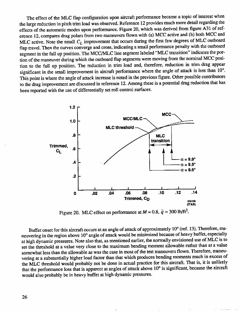
The effect of the MLC flap configuration upon aircraft performance became a topic of interest when
the large reduction in pitch trim load was observed. Reference 12 provides much more detail regarding theeffects of the automatic modes upon performance. Figure 20, which was derived from figure A31 of ref-erence 12, compares drag polars from two maneuvers flown with (a) MCC active and (b) both MCC andMLC active. Note the small CL improvement that occurs during the fhst few degrees of MLC outboardflap travel. Then the curves converge and cross, indicating a small performance penalty with the outboardsegment in the full up position. The MCC/MLC line segment labeled "MLC transition" indicates the por-tion of the maneuver during which the outboard flap segments were moving from the nominal MCC posi-
tion to the full up position. The reduction in trim load and, therefore, reduction in trim drag appear
significant in the small improvement in aircraft performance where the angle of attack is less than 10°.This point is where the angle of attack increase is noted in the previous figure. Other possible contributorsto the drag improvement are discussed in reference 12. Among these is a potential drag reduction that has
been reported with the use of differentially set roll control surfaces.
1,2 -
MCC-N
1.0- MCC/MLC--_
MLCthreshold_.8- /I MLC
T O_= 8.6 °
•2 -
I I I I I I I0 .02 .04 .06 .08 .10 .12 .14
Trimmed, C D(ITAR)
Figure 20. MLC effect on performance at M = 0.8, _ = 300 lb/ft 2.
Buffet onset for this aircraft occurs at an angle of attack of approximately 10° (ref. 13). Therefore, ma-
neuvering in the region above 10° angle of attack would be minimized because of heavy buffet, especiallyat high dynamic pressures. Note also that, as mentioned earlier, the normally envisioned use of MLC is toset the threshold at a value very close to the maximum bending moment allowable rather than at a valuesomewhat less than the allowable as was the case in most of the test maneuvers flown. Therefore, maneu-
vering at a substantially higher load factor than that which produces bending moments much in excess ofthe MLC threshold would probably not be done in actual practice for this aircraft. That is, it is unlikelythat the performance loss that is apparent at angles of attack above 10° is significant, because the aircraftwould also probably be in heavy buffet at high dynamic pressures.
26
CONCLUDING REMARKS
A comparison of aircraft component loads data between a maneuver load control (MLC) flap config-uration and a baseline configuration using manually positioned, uniformly deflected flaps has been pre-sented for an aircraft having a modified supercritical wing with a continuously variable camber airfoil.Flight test data were collected at Math 0.6, 0.7, 0.8, and 0.9 and dynamic pressures tested were 300, 450,600, and 800 lb/ft 2. All data presented were obtained at a wing-sweep position of 26° and compared witha baseline flap configuration.
Significant load reductions were obtained at all flight conditions tested with the MLC configuration.For dynamic pressures of 450 to 800 lb/ft 2, increases in load factor of 0.8 to 1.0 g were achieved with theMLC flap configuration at the same wing-root bending moments measured for the corresponding baselineflap configuration. Although wing-root torsion load reductions resulting from MLC were found through-out the Mach-number range flown, the most beneficial effect for torsion was seen at Mach 0.9.
Horizontal tail pitch trim loads also were reduced significantly with the MLC flap configuration. Thistrim load reduction may be responsible for the small beneficial effect which MLC had on aircraft perfor-mance for some flight conditions where the angle of attack was less than 10°.
Dryden Flight Research FacilityNational Aeronautics and Space AdministrationEdwards, California, August 8, 1993
27
h
...... r .......
REFERENCES
1. Mechtly, E.A., The International System of Units - Physical Constants and Conversion Factors, Sec-ond Revision, NASA SP-7012, 1973.
2. Powers, Sheryll Goecke, ed., Advanced Fighter Technology Integration F-111 Mission AdaptiveWing, symposium proceedings published as NASA CP-3055, (ITAR), 1990.
3. Thornton, Stephen V., Structural Loads With Maneuver Load Control for the Advanced Fighter Tech-nology Integration/F-111 Mission Adaptive Wing, NASA TM-4404, 1992.
4. Hall, Joseph M., AFTI/F-111 Flight Control System, AFWAL-TR-87-3012, Flight Dynamics Labo-ratory, Air Force Wright Aeronautical Laboratories, Air Force Systems Command, Wright-PattersonAir Force Base, Ohio, Dec. 1987.
5. Anderson, D.C., R.L. Berger, and J.R. Hess, Jr., "Maneuver Load Control and Relaxed Static StabilityApplied to a Contemporary Fighter Aircraft," AIAA 72-870, AIAA Guidance and Control Confer-ence, Stanford, California, Aug. 1972.
6. White, Roland J., "Improving the Airplane Efficiency by Use of Wing Maneuver Load Alleviation,"AIAA 70-877, CASI/AIAA Meeting on the Prospects for Improvements in Efficiency of Flight, Tor-onto, Canada, July 1970.
7. Hodges, Garold E., and James R. McKinzie, "B-52 Control Configured Vehicles Maneuver LoadControl System Analysis and Flight Test Results," AIAA 75-72, AIAA 13th Aerospace SciencesMeeting, Pasadena, California, Jan. 1975.
8. North American Rockwell Corporation, Analysis of Relaxed Static Stability and Maneuver Load Con-trol Applications to a Large Bomber, AD-784865, Dec. 1971.
9. Baldwin, Wayne, ed., Symposium on Transonic Aircraft Technology (TACT), AFFDL 78-100, AirForce Flight Dynamics Laboratory, Wright-Patterson Air Force Base, Ohio, Aug. 1978.
10. Skopinski, T.H., William S. Aiken, Jr., and Wilber B. Huston, Calibration of Strain-Gage Installa-tions in Aircraft Structures for the Measurement of Flight Loads, NACA Rept. 1178, 1954.
11. Webb, Lannie D., Sheryll Goecke Powers, and Lucinda A. Rose, SelectedLocaIFlow-Field Measure-ments on the Advanced Fighter Technology Integration (AFTI)/F-111 Aircraft Mission Adaptive
- Wing, NASA TM-4405, 1992.
12. Phillips, W. Paul, "Lift and Drag Characteristics of the AF'TI/F-111 With the MAW Automatic Con-trol Modes," Advanced Fighter Technology Integration F-111 Mission Adaptive Wing, NASA CP-3055, 1990, pp. 263-283.
13. Friend, Edward L., and Jeffrey M. Thompson, "Buffet Characteristics of the Advanced Fighter Tech-nology Integration (AFTI)/F-111 Airplane with the Mission Adaptive Wing," Advanced FighterTechnology Integration F-111 Mission Adaptive Wing, NASA CP-3055, 1990, pp. 197-222.
28

REPORT DOCUMENTATIONPAGE FormApprovedOMBNo.0704-0188
Public reposing bu_n lor thiscollectionof Informationb wtirnamd to average I hourperruponse, Indudk_gthe time for reviewingInstructions,eamrchk_0 exlst_g data sourcss,gatheringandmaintainingthedataneeded,andcompletingandreviewingtheco;leclionof information.Sendo_mmentsregardingthisburdenestlmmeoranyotheraspectofthiseollecUonof infonmtion, i'_ludingsug_lor_ for reducingthis burden, to WashingtonHeedquattefl=S_, DirectorateforInformatlonOporJelons_ Reports,1215 Je_Davis Highway,Suite 1204, Arlington,VA22202-4302, andto the Offioe of Managementand Budget,PaperworkReductionProject(0704-0188), Washington,DC 20503.
1.AGENCYUSEONLY(Leaveblank) 2. REPORTDATE 3. REPORTTYPEANDDATESCOVERED
September 1993 Technical Memorandum4. TITLE AND SUBTITLE 5. FUNDING NUMBERS
Reduction of Structural Loads Using Maneuver Load Control on the AdvancedFighter Technology Integration (AFrI)/F-111 Mission Adaptive Wing
6.AtrmOR(S) WU 505-63-50
StephenV.Thornton
7. PERFORMING ORGANIZATION NAME(S) AND ADDRESS(ES) 8. PERFORMING ORGANIZATIONREPORTNUMBER
NASA Dryden Flight Research Facility
P.O. Box 273 H-1940Edwards,California 93523-0273
9. SPONSORING/MONOTORING AGENCY NAME(S) AND ADDRESS(ES) 10. SPONSORING/MONITORINGAGENCYREPORTNUMBER
National Aeronautics and Space AdministrationWashington, DC 2054649001 NASA TM--4526
11.SUPPLEMENTARYNOTES
12J.DISTRIBUTIOWAVAILABIUTYSTATEMENT 12b. DISTRIBUTIONCODE
Unclassified--Unlimited
SubjectCategory02
13. ABSTRACT (Maximum 200 words)
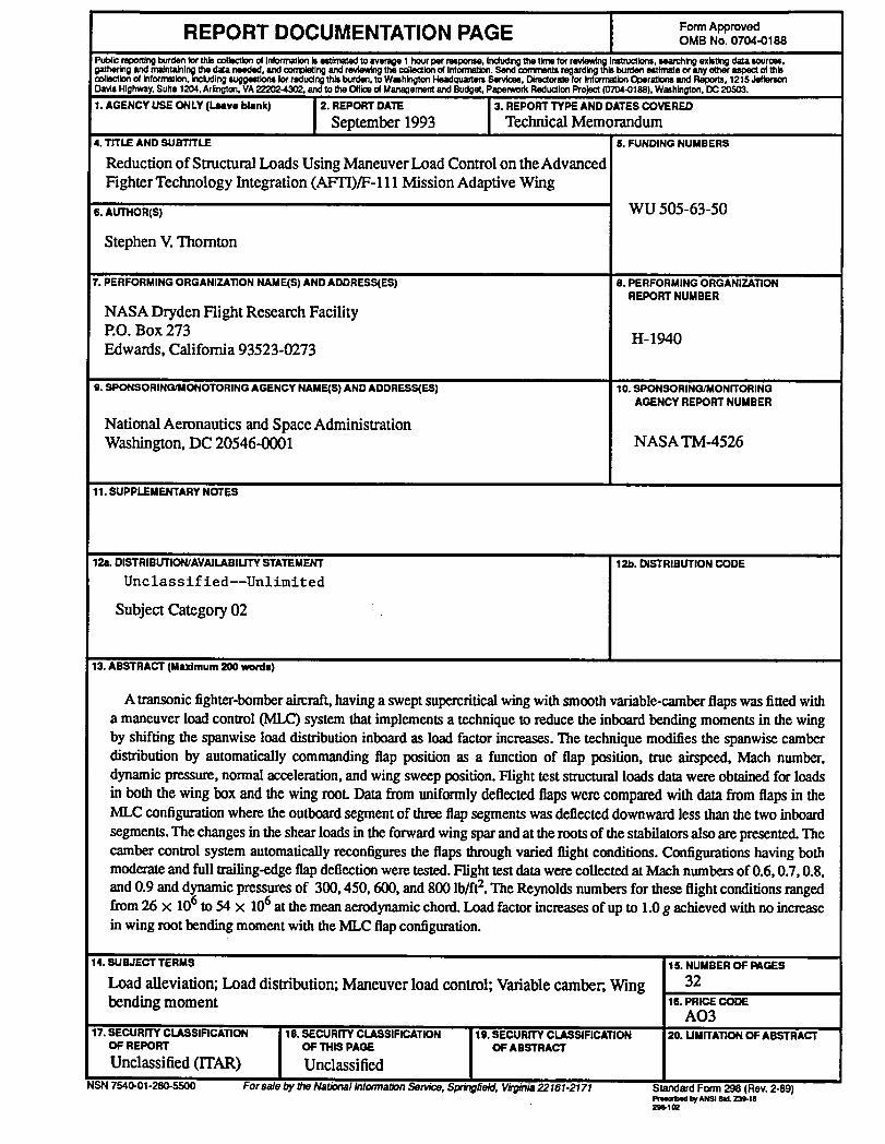
A transonic fighter-bomberaircraft, having a sweptsupercritical wing with smooth variable-camber flaps was fitted witha maneuver load control (MLC) system that implements a technique to reduce the inboard bending moments in the wingby shifting the spanwise load distributioninboardas load factor increases.The technique modifies the spanwise camberdistribution by automatically commanding flap position as a function of flap position, true airspeed, Mach number,dynamic pressure, normal acceleration, and wing sweep position. Flight test structuralloads data were obtained for loadsin both the wing box and the wing rooL Data from uniformly deflected flapswere compared with data from flaps in theMLC configuration where the outboardsegment of threeflap segments was deflected downward less than the two inboard
segments. The changes in the shear loads in the forwardwing sparand at the roots of the stabilatorsalso are presented.Thecamber control system automatically reconfiguresthe flaps through varied flight conditions. Configurations having bothmoderateand full trailing-edge flap deflection were tested.Fright test data were collected atMach numbers of 0.6, 0.7, 0.8,
and 0.9 and d_c pressures of 300, 450, 600, and 800 lb/ft2. The Reynolds numbers for these flight conditions rangedfrom 26 X 10 to 54 X 106at the mean aerodynamic chord.Load factor increasesof up to 1.0 g achieved with no increaseinwingrootbendingmomentwiththeMLCflapconfiguration.
14. SUBJECT TERMS 15. NUMBER OF PAGES
Loadalleviation;Loaddistribution;Maneuverloadcontrol;Variablecamber;,Wing 32bending moment 16. PRICE CODg
AO317. SECURITY CLASSIFICATION 18. SECURITY CLASSIFICATION 19. SECURITY CLASSIFICATION 20. UMITATION OF ABSTRACT
OF REPORT OF THIS PAGE OF ABSTRACT
Unclassified0TAR) UnclassifiedNSN 7540-01-280-5500 For sale by the National Informabon Service, Spr_gfietd, Virginia22161-2171 Standard Form298 (Rev.2-89)
Ptuetl_a bl ANSlStJ.z3e.ta2_.1to

National Aeronautics and " 3 1176 01409 6078 SPECIALFOURTH-CLASSRATE
SpaceAdministration POSTAGE AND FEES PAIDNASACode JTT PERMIT No. G27
Washington, D.C.20546-0001Official BusinessPenalty for Private Use, $300
_.__,_ POSTMASTER: If Undeliverable (Section 158
Y,dP' Postal Manual) Do Not Return