
Reduction of Emissions by Optimal use of Gas Turbines · Reduction of Emissions by ......
24
Reduction of Emissions by By Terence G. Hazel Senior Member IEEE Optimal use of Gas Turbines
Transcript of Reduction of Emissions by Optimal use of Gas Turbines · Reduction of Emissions by ......

Reduction of Emissions by
By Terence G. Hazel Senior Member IEEE
Optimal use of Gas Turbines

Summary
...................................................................................... p.1
Introduction..................................................................................................p.2
Basic.concepts.............................................................................................p.4
Frequency.control.&.Dry€Low€NOx. operation .............................................. p.8
Voltage.control............................................................................................p.10
Implementation.of.algorithms......................................................................p.12
Case.study.................................................................................................p.13
PMS.implementation..................................................................................p.17
Conclusion p.20
References.................................................................................................p.21
Executive€summary
.................................................................................................
of€Emissions€by OptimaI.use.of.Gas.Turbines.Reduction

COM-POWER-WP0�EN Rev1 | 1
Executive summary
Large.facilities.are.often.powered.by.gas.turbines..In.many.cases.turbines.
having.different.ratings.and.operating.characteristics.are.used.at.the.same.
site..The.decision.regarding.which.turbines.to.use.and.when.is.not.an.easy.
one.to.make.since.several.constraints.must.be.taken.into.account...
Some.of.these.are:
maintain .sufficient.spinning.reserve
operation.at.low.NOx.emission.levels
poor.dynamic.response.of.larger.sized.turbines
us . .Heat.Recovery.Steam.Generators
sufficient.power.for.all.production.islands.
Some.of.these.criteria.can.be.contradictory..For.example,.operation.at.low.
NOx.emission.levels.requires.a.high.load.on.the.turbine,.but.high.load.on.
turbines.often.means.lower.spinning.reserve.and.unequal.load.sharing,.both.
of.which.can.be.detrimental.to.system.stability.
The.paper.will.explore.the.different.aspects.that.must.be.taken.into.account.
in.the.optimal.selection.of.which.turbines.to.use.under.different.operating.
conditions€to€ .It .also.describes
.the.minimum.requirements .of .the.Power .Management .System. (PMS).
that
.
is
.
necessary.to.implement.this.optimization.
•••••
enhance€the€ .
of€Emissions€by OptimaI.use.of.Gas.Turbines.Reduction
ing
ing
reliability€of€the€suppfly€of€power
COM-POWER-WP0�EN Rev1 | �
Introduction
Gas.Turbines.(GTG).and.Steam.Turbines.(STG).often.provide.much,.if.not.all.
of.the.power.necessary.for.the.process.at.petrochemical.plants..They.are.
therefore.very.important.pieces.of.equipment.and.must.be.carefully.selected.
in.order.to.fulfill.the. requirements. . .:
sufficient.power.at.rated.frequency.for.all.loads
correct.voltage.at.all.load.busbars
robustness.to.ride.through.system.disturbances.
In.addition.there.are.several.environmental.constraints.that.must.be.met,.one.
of.which.is.the.emission.level.of.Nitrogen.Oxides.(NOx)..Modern.GTGs.use.
combustion.methods.which.limit.NOx.emission.without.the.use.of.water.or.
steam.injection,.a.process.called.Dry.Low.NOx .combustion (DLN).
This. .consists .of .mixing . . gas.thus. recording .
the.formation.of.NOx..This.type.of.combustion.however,.requires.
that.the.GTGs.operate.at.certain.minimum.power.output.levels.which.are..
a.function.of.the.air.inlet.temperature.
Another.environmental.constraint.is.the.increase.in.efficiency.in.order.to.
produce.more.MW.per.unit.of.gas..Cogeneration.is.a.method.commonly.used.
and.consists.of.producing.steam.from.the.exhaust.gas.of.the.GTGs.to.power.
steam.turbines..While.this.increases.efficiency,.it.makes.the.reliable.operation.
of.the.GTGs.even.more.important.since.the.loss.of.a.GTG.will.not.only.reduce.
the.available.power.of.the.gas.turbine,.but.also.of.the.associated.steam.
turbine.running.off.of.the.heat.of.the.GTG.exhaust.gas.
It.is.thus.very.important.that.extensive.engineering.studies.be.carried.out.
during.the.Front.End.Engineering.Design.(FEED).to.ensure.that.the.correct.
number.and.size.of.GTGs.are.selected..This.will.depend.on.the.plant.load.but.
also.on.the.design.of.the.electrical.distribution.system..As.will.be.shown,..
the.use.of.distributed.generation.can.make.the.designing.of.power.
systems.quite.complicated..Since.the.steam.supply.is.very.important.when.
cogeneration.is.used,.it.must.be.decided.if.independent.firing.means.are..
to.be.used.in.addition.to.the.heat.recovery.systems.
For.illustration.purposes.in.this.paper,.the.system.frequency.is.50.Hz.and..
40.MW.and.90.MW. . .are.considered..There.is.no.difference.when.
60.Hz.is.used.or.GTGs.with.other.power.output.ratings.
•••
GTGs
following
better of air and
of€Emissions€by OptimaI.use.of.Gas.Turbines.Reduction
ensuring

Optimal use of Gas Turbines
Reduction of Emissions by

COM-POWER-WP0�EN Rev1 | �
Robust Control
A.system.is.“robust”.when.it.can.withstand..
severe.disturbances.and.keep.operating.within.
acceptable.limits..A.power.system.must.be.robust.
in.order.to.be.able.to.provide.power.to.loads.even.
when.faults.occur.such.as.short-circuit.conditions.
or.the.loss.of.a.GTG.or.STG..Since.electrical.
energy.that.is.produced.is.immediately.consumed.
without.any.intermediate.storage,.a.sudden.loss..
of.power.will.result.in.an.immediate.decrease..
in.system.frequency..A.short.circuit.causes..
a.decrease.in.active.power.consumption.due.to..
a.loss.of.voltage.at.the.fault.location..This.results.in.
an.immediate.increase.in.system.frequency...
A.robust.system.must.react.very.quickly.to.such.
disturbances.by.changing.the.operating.points
..
of.the.turbine.governors,.as.well.as.the.generator
.
and.transformer.AVRs..The.primary.regulation
.
associated.with.this.equipment.can.provide.
the.rapid.response.required.provided.that.the.
power.system.is.designed.accordingly.as.will.be.
discussed.hereafter.
The .primary .regulation .must .be .able.to.rapidly.
restore.the.balance.between.generation.and
.load..It.operates.with.no.consideration.for.the
.location.of.the.initial.imbalance..Primary.regulation
.can.be.implemented.in.several.manners.–.it.is.the.
responsibility.of.the.power.system.engineer.to.
determine.which.mode.is.correct..The.goal.of.
primary.regulation. . . . .keep ..the.frequency.
within.±0.5.Hz.and.. ..±5.%.
after.a.disturbance.has.occurred...The
.frequency. steady-state.error.
. less.than.. 150.mHz.
Basic concepts
Secondary.regulation.operates.at.a.global.
level..After.the.transient.conditions.following.
a.disturbance.have.subsided,.the.secondary.
regulation.will.send.±.set.point.changes.to..
the.GTG.and.STG.governors.to.bring.the.
frequency.back.to.its.nominal.value,.and.to..
ensure.correct.load.sharing.among.the.turbines..
It.will.also.send.±. set. point. changes. to. generator.
and.transformer .AVRs.in.order.to.ensure.correct.
voltage.levels.throughout.the.system..Secondary.
regulation.will.also.ensure.reactive.power.sharing.
The.key.points.of.robust.control.are.therefore:
separate ..global.&.local.control.functions.(Fig..1)
local.control.implement .in.primary.regulation
global.control.implemented.in.a.PMS
communicatie.between.control.layers.using.
incremental.values.(±.set.points).
Secondary regulation,set point changes
Optimizing equipmentoperating points
Global controllayer
Incremental set-point changes
Primary regulation,governor, AVR
Local controllayer
Turbine, generator,transformer
Stand-aloneregulation of electrical equipment
Power generation &transmission equipment
Figure 1 – Robust control philosophy
••••
of€Emissions€by OptimaI.use.of.Gas.Turbines.Reduction
is€to and
voltage deviation
of
should€be
provide
Un

COM-POWER-WP0�EN Rev1 | �
The.local.controllers.should.implement.control.
based.on.droop.characteristics..Turbines.should.
all.operate.at.a.4%.frequency.droop..The.use.of.
droop.characteristics.will.ensure.that.all.turbines.
react.in.the.same.manner.to.disturbances.and.this.
greatly.enhances.the.ability.of.the.power.system.to.
recover.correctly..Fig..2.shows.2.GTGs.operating.
in.frequency.droop.and.sharing.the.load.–.each.
GTG.supplies.the.same.percentage.power.based.
on.its.maximum.rated.output..When.the.plant.load.
increases,.the.GTG.primary.regulation.will.detect.a.
decrease.in.system.frequency.and.will.increase.the.
GTG.power.output.to.compensate...Due.to.the.4.%
.droop.setting,.the.new.operating.point.will.be.at.a
.slightly.lower.but.still.acceptable.frequency.as.
shown.in.Fig..3.
FrequencyHz
51
50 Hz
49
MW
90 MW GTG
7560
40 MW GTG
20
20 MW 45 MW
40 90
Figure 2 – Primary regulation in frequency droop
Isochronous.or.fixed.power.modes.should.not.be.
used.except.for.very.specific.operating.conditions..
As.will.be.discussed.later,.the.use.of.DLN.turbines.
introduces. additional. operation. constraints.
When .generators.are.directly.connected.to.. the. same. busbar,. their. AVRs. should. operate.
at..a.5.%.voltage. droop.
40
FrequencyHz
51
50
49
MW
90 MW GTG
7560
40 MW GTG
20
49.75 Hz
25 MW 56.3 MW
90
Figure 3 – Operating points after load increase
When.generators.are.connected.to.busbars.via.
step-up.transformers,.the.transformer.impedance.
ensures.the.voltage.droop.characteristic,.and.it.is.
recommended.to..set.these.generator.AVRs.to.
fixed.voltage...In.some.cases,.busbars.will.be.also
.be.supplied.by.transformers.which.import.power.
from
.
other
.
sources.in.the.system.(Note:.
Transformers.can.control.the.flow.of.reactive.
power.but. do. not. produce
.
any.).. The. AVRs. of.
these.transformers.should.also.operate.at.a.5.%.
voltage.droop.thus.contributing.to.maintaining.
the.busbar.voltage.in. the.same.manner.as.the.
generators.
[1]...
This.
avoids.conflicts. that.can.occur.when. .
.with€have€.different .operating.modes.and.
characteristics
.
try
.
to. control. the. voltage. on.. the. same.
busbar..It.is. also.possible.in.some.cases.to.allow.the
.transformer.to.supply.the.reactive.power.necessary.
to.maintain.the.busbar.voltage.and.to.operate.the.
generators.at.fixed.power.factor..Generators.
operating
.
at
.
fixed
.
power. factor. however,. are. not.
able.to.contribute.to.maintaining.system.voltages.
after.a.disturbance.has.occurred.
Primary Regulation of GTGs and STGs
generators and tansformers which
of€Emissions€by OptimaI.use.of.Gas.Turbines.Reduction
COM-POWER-WP0�EN Rev1 | �
Fast Load Shedding
In.some.cases.it.is.not.possible.for.the.primary.
regulation.to.keep.the.power.system.within..
the.limits.defined.above.after.a.disturbance.has.
occurred..One.reason.can.be.the.limitation.of.
the.dynamic.release.of.reserve.power.from.large.
turbines.as.will.be.discussed.in.a.later.section...
The.only.means.of.preventing.a.collapse.of..
the.power.system.in.such.cases.is.to.shed.
sufficient.load.quickly.enough.that.the.generation.
can.continue.to.supply.the.priority.loads...
Plant-wide.fast.load.shedding.is.one.of.the.typical.
functions.implemented.in.a.PMS.
The.level.of.security.is.defined.taking.into.
account.credible.contingencies,.called.“normative.
incidents”,.for.which.the.power.system.is.
supposed.to.remain.within.the.limits.defined.above..
Primary.regulation.cannot.ensure.that.nominal.
values.of.frequency.and.voltage.are.present.
throughout.the.power.system..Global.control.is.
required.and.is.provided.by.the.PMS...
The.PMS.measures.the.system.frequency,.busbar.
voltages.and.power.output.of.the.turbines.and.will.
change.the.set.points.of.the.primary.regulation.in.
order.to.ensure:
correct.frequency
correct.busbar.voltages
DLN.operation.where.possible
equal.sharing.of.load.as.a.percentage.of.rated.
power.
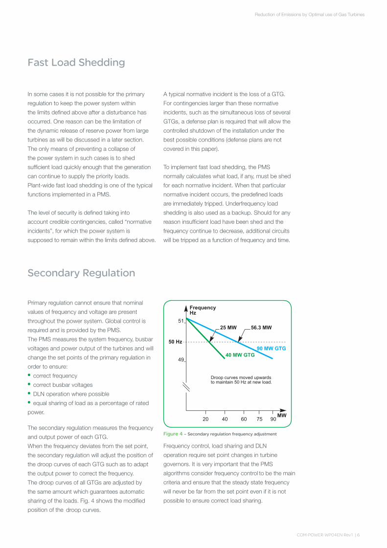
The.secondary.regulation.measures.the.frequency.
and.output.power.of.each.GTG...
When.the.frequency.deviates.from.the.set.point,.
the.secondary.regulation.will.adjust.the.position.of.
the.droop.curves.of.each.GTG.such.as.to.adapt.
the.output.power.to.correct.the.frequency...
The.droop.curves.of.all.GTGs.are.adjusted.by..
the.same.amount.which.guarantees.automatic.
sharing. of. the. loads.. Fig.. 4. shows. the.modified.
droop.curves..
••••
FrequencyHz
51
50 Hz
49
MW756020
Droop curves moved upwardsto maintain 50 Hz at new load.
90 MW GTG40 MW GTG
25 MW 56.3 MW
40 90
Figure 4 – Secondary regulation frequency adjustment
Frequency.control,.load.sharing.and.DLN.
operation.require.set.point.changes.in.turbine.
governors..It.is.very.important.that.the .PMS .
algorithms.consider.frequency.control . be.the.main.
criteria.and.ensure.that.the.steady.state.frequency.
will.never.be.far.from.the.set.point.even.if.it.is.not.
possible.to.ensure.correct.load.sharing...
A.typical.normative.incident.is.the.loss.of.a.GTG..
For.contingencies.larger.than.these.normative.
incidents,.such.as.the.simultaneous.loss.of.several.
GTGs,.a.defense.plan.is.required.that.will.allow.the.
controlled.shutdown.of.the.installation.under.the.
best.possible.conditions.(defense.plans.are.not.
covered.in.this.paper)...
.
To.implement.fast.load.shedding,.the.PMS.
normally.calculates.what.load,.if.any,.must.be.shed.
for.each.normative.incident..When.that.particular.
normative.incident.occurs,.the.predefined.loads.
are.immediately.tripped..Underfrequency.load.
shedding.is.also.used.as.a.backup..Should.for.any.
reason.insufficient.load.have.been.shed.and.the.
frequency.continue.to.decrease,.additional.circuits.
will.be.tripped.as.a.function.of.frequency.and.time.
Secondary Regulation
of€Emissions€by OptimaI.use.of.Gas.Turbines.Reduction
to
position€of€the

COM-POWER-WP0�EN Rev1 | �
As.an.example,.consider.a.governor.of.a.lightly.
loaded.turbine.not.responding.to.set.point.
changes.from.the.PMS.due.to.some.internal.fault.
condition..In.order.to.achieve.load.sharing,.the.
PMS.must.increase.the.load.of.this.turbine.but.at.
the.same.time.decrease.the.load.on.other.turbines.
in.order.to.avoid.any.changes.in.frequency..Since.
the.faulty.governor.does.not.respond.to.set.
point.increases,.it.will.not.increase.its.load.whereas.
the.other.turbines.will.respond.to.the.PMS.set.
point.changes.and.decrease.their.power.output..
The.result.will.be.a.decrease.in.frequency..Should.
the.frequency.decrease.below.the.dead-band.value,.the.PMS.must.immediately.cease.attempts.
to.share.the.load.since.that.would.result.in..
an.unacceptable.decrease.in.system.frequency.
Secondary.regulation.does.not.react.quickly.and.
should.not.react.quickly..It.is.used.to.“fine.tune”.
the.power.system.by.bringing.frequency,.voltage.
and.power.values.within.steady.state.tolerances..
Attempting.to.change.state.values.too.quickly.
could.cause.instabilities.and.power.outages...
In.addition,.the.reaction.of.primary.regulation.to.set.
point.changes.is.inherently.slow.and.even..
if.the.secondary.regulation.tried.to.quickly.change.
set.points,.it.couldn’t.do.so.
The.basis.for.power.system.design.is.knowing.
how.the.system.will.react.to.contingencies...
For.green.field.projects,.or.for.large.extensions.to .
existing.facilities,.simulations.must.be.carried.out.
since.it.is.not.possible.to.make.measurements..
The.simulations.must.calculate.the.transient.and.
steady.state.frequency,.active.and.reactive.power.
flow,.and.busbar.voltages.immediately.after.
contingencies..In.many.cases.it.is.necessary.to
.conduct.simulations.over.a.long.period.of.time.to.
ensure.that.the.power.system.remains.stable.after.a.major.disturbance..Short-time.simulations.may.
show.that.the.power.system.recovers. correctly.
after.a.contingency.only.to.find . .
after
.
several
.
seconds,.the.power. system. actually.collapses.
The.transfer.functions.of.the.turbine.governor,.
and.the.generator. and.transformer.AVRs.must.
be.well.known.in.order.to.perform.such.
simulations...This.information.is.unfortunately.
difficult.to.get...As.will.be.discussed,.the.dynamic.release.of.reserve.power.is.often.much.
less.than.would.be.expected.and.must.be.
correctly.simulated.[2].
System Calculations and Simulations
at€the site€out
actually
that€
of€Emissions€by OptimaI.use.of.Gas.Turbines.Reduction

COM-POWER-WP0�EN Rev1 | �
Frequency control & DLN operation
Frequency.control.and.active.power.sharing.
among.turbines.is.very.important.and.often.
referred.to.as.P/f.control..Implementation.of.
DLN.operation.adds.to.the.complexity.of.the.P/f.
control.algorithms..In.order.to.reduce.the.NOx.
concentrations.in.exhaust.gas,.the.air/gas. . .must€be€homogeneous .This.can,.however,..
only.be.achieved.when.the.turbine.output.exceeds..
a.certain.percentage.of.its.nominal.rating.as..
a.function.of.the.air.inlet.temperature..Fig..5.shows.
the.relationship.between.the.DLN.limit.and..
the.maximum.power.output..Both.depend.on.
the.air.inlet.temperature.(shown.on.the.abscissa)..
The.ordinate.is.in.percent..From.Fig..5.it.can.be.
seen.that.for.DLN.operation,.the.turbine.output.
must.generally.exceed.60.%.of.the.nominal.rating..
Since.operation.close.to.the.DLN.limit.can.result.in.instability,.it.is.necessary.to.ensure.that.the.turbine.
output.is.either.well.above.or.well.below.the.DLN.
limit..This.constraint.does.not.apply.to.turbines.
that.do.not.have.the.capability.of.DLN.operation.
nor. to.steam.turbines.
As.mentioned.in.the.previous.section,.equal.
sharing.of.the.load.as.a.percentage.of.nominal.power.is.important.since.it.enhances.the.capability.of.the.power.system.to.respond.correctly.to.
contingencies..Equal.sharing.is.always.possible.when.no.turbines.operate.in.the.DLN.mode.
since.there.are.no.constraints.regarding.output.power.other.than.exceeding.the.minimum.or.
maximum.power.output..It.is.easy.to.meet.
these.requirements.since.these.points.are.at.the.extremes.of.the.turbine.output.capability.curves..When.DLN.operation.is.used,.it.is.not.possible.to.
ensure.equal.loading.among.all.turbines.
44244-16-3600
25
50
75
100Maximum Output
DLN limit
Figure 5 – DLN limits as function of temperature
As.an.example,.consider.several.non-DLN.GTGs.
supplying.the.load..As.shown.in.Fig..2,.3.and.4,.
operation.in.4.%.frequency.droop.will.automatically.
ensure.that.load.is.shared.equally.as.a.percentage.
of.nominal.power..Should.the.plant.load.increase,.
the.steady-state.frequency.will.decrease.and..
the.PMS.will.send.the.same.set.point.adjustments.
to.all.governors.to.increase.the.GTG.output.thus.
bringing.the.frequency.back.to.its.nominal.value.
and.ensuring.correct.load.sharing.at.all.times...
This.is.true.for.all.values.of.output.power.
Should,.however,.one.of.the.GTGs.operate.in.
the.DLN.mode,.it.is.no.longer.possible.to.have.
identical.load.sharing.among.the.machines.since.
it.is.necessary.to.ensure.that.the.DLN.machines.
operate.far.from.the.DLN.limit..Secondary.
regulation.is.used.to.ensure.operation.far.from.
the.DLN.limit..This.is.achieved.by.considering.two.
different.values.of.minimum.output.for.the.DLN.
machine..At.low.load,.the.minimum.output.will.be.
a.few.%.of.the.nominal.rating..Operation.of.the.
DLN.GTG.can.then.be.at.the.same.%.output.as.
all.other.GTGs.since.at.light.load.the.output.will.be.
far.below.the.DLN.limit.which.is.close.to.60.%.of.
rated.power..When.the.plant.load.is.high.however,.
the.DLN.GTG.must.be.made.to.operate.well.above.
the.DLN.limit..For.this.case,.the.minimum.output.
used.is.the.DLN.limit..Secondary.regulation.will.
ensure.that.the.%.load.within.this.range.(DLN.limit.
to.maximum.output).is.the.same.as.the.%.load.of.
all.other.GTGs,.their.range.being.between.the.
minimum.and.maximum.values..This.is.shown.in. Fig..6..
FrequencyHz
51
50 Hz
49
MW756020
DLN Limit
90 MW GTG
40 MW GTG
12.2 MW
40
65 MW
90
Figure 6 – Operation above the DLN limit
%Pn
Co
mixture.
of€Emissions€by OptimaI.use.of.Gas.Turbines.Reduction

COM-POWER-WP0�EN Rev1 | �
The.dashed-line.portion.of.the.droop.curve.of.the.90.MW.GTG.corresponds.to.output.values.below.the.DLN.limit..The.GTG.is.not.to.operate.there.at.high.load..This.range.is.from.0.MW.to.54.MW.(60.%.of.the.rated.output)..The.solid-line.portion.of.the.droop.curve.of.the.90.MW.GTG.is.the.permissible.operating.range.and.equals.36.MW.(90.MW.–.54.MW)..The.%.loading.“x”.is.based.on.the.total.power.required.“P”. . .
P.=.(x(36).+.54).+.x(40)€;.. x.=.P.-.5476
The.power.supplied.by.the.GTG.is.65.MW.which.exceeds.the.DLN.limit.by.a.comfortable.11.MW...11.MW.is.equal.to.30.5.%.of.the.permissible.36.MW.operating
.range.
..The. other. GTG. shall. also. operate. at.
30.5.%.of.its.range,.but.its.range. is. between. 0. MW.and
.40
.MW.
.Its.operating.point.is..12.2.MW...Thus
.although.the.%.loading.within.the.operating.ranges.are.the.same,.the.%.loading.based.on.the.total.output.capacity.is.not..The.DLN.GTG.is.operated.at.a.higher.%.load.than.the.other.GTG.
When.a.load.step.occurs,.the.primary.regulation.of.all.turbines.will.react.to.increase.the.power.output.but.at.a.slightly.lower.frequency..As.shown.in..Fig..7,.primary.regulation.will.change.the.operating.point.along.the.droop.curves.without.taking.into.account.DLN.operation..
FrequencyHz
51
50
49
MW756020
DLN Limit
90 MW GTG40 MW GTG
17 MW
76 MW
40 90
Figure 7 – Reaction of DLN turbine to step load
The.DLN.turbines.are.intially.too.heavily.loaded.–.76.MW.corresponds.to.61.%.of.the.DLN.operating.range.whereas.17.MW.corresponds.to
.only.42.5.%.of.the.non-DLN.operating.range..
It.is.the.secondary.regulation.that.will.ensure.that.the.correct.operating.positions.of.all.DLN.and..non-DLN.turbines. Fig..8.shows.the.operating.points.after.secondary.regulation.has. .modified
.the.governor. set. points. of. all. turbines.. The.output
.of.the.DLN.
turbines.
was. decreased. and.that.of.the.non-DLN.turbines.increased..The.new.loading.factor.is..51.3.%.for.all.turbines.
FrequencyHz
51
50 Hz
49
MW756020
DLN Limit
90 MW GTG40 MW GTG
20.5 MW
72.5 MW
40 90
Figure 8 – Correction of DLN turbine loading
Even.if.all.GTGs.operate.in.DLN.mode,.there.may.be.situations.where.load.sharing.cannot.be.achieved..In.the.previous.example,.consider.that.both.GTGs.could.operate.in.a.DLN.mode..Should.plant.load.be.close.to.78.MW,.which.is.60.%.of.the.total.generation .capacity, .it .would .not€be .possible .to .
equally
.share.the.load.since.this.would.result.in.the.
GTGs.
operating.at.their.DLN.limit. ..One.GTG.mustbe.selected.to.operate. at. a. higher. rated.
load
.
and
.the.other. at. a. lower. rated. load.. Both. GTGs
.will.thus. be.operating.far.from..their.DLN.limits.but. .
.will
.not
.equally
.share
.
the
.
load.
.During .disturbances,.the.primary.regulation. of. all.turbines .will. react. based. on. the. 4. %. frequency.droop.curve.only,.as.shown.in.Fig..2...The.minimum.value.used. by. the. PMS. to. determine. the. operating.points.of.DLN.GTGs. has. no. influence. on.the.dynamic.response. of. the. turbines... Simulations.should.be.made.to.check.that..the.power.system.remains.stable.when.some.GTGs.are.more.heavily.loaded
.than
.others
.due.to. the.DLN.constraints..
After.the.transients.have.died.down.(and.possibly.load.shedding),.the.PMS.will.recalculate.the.power.output.that.each.GTG.should.have.and.send.the.required.incremental.set.point.changes.to.each.GTG.
of€Emissions€by OptimaI.use.of.Gas.Turbines.Reduction
is:
therefore

COM-POWER-WP0�EN Rev1 | 10
Voltage control
Voltage.control.and.reactive.power.sharing.is.often
.
referred.to.as.Q/V.control..Voltage.control.in..
a.power.system.is.very .different .from .frequency .
control..The.frequency.is.the.same.throughout.
the.whole.power.system.and.is.not.influenced.by.
.transformers..The.primary.regulation.of.all.
turbines.therefore.react.to.the.same.state.variable
.
no.
matter
.
where.a.turbine.is.located. ..Voltage,. on
.
the.other.hand,.is.a.local.state.variable.and.can.
differ.greatly.throughout.the.power.system..It.is.
the.impedances.in.the.power.system.(lines.&.
transformers).that.decouple.the.voltage.levels.at
.
different.locations..Frequency.control. is. made.
by.adjusting.the€power. output.of.the.turbines..
Voltage
.
control.requires.adjusting.the.reactive.
power
.
output.of.the.generators.but.also
.changing.the .tap.positions.of.transformers.
When.all.power.sources.are.connected.to..
the.same.busbar,.the.generator.AVRs.will.ensure
.
that.the.voltage.on.that.busbar.is.correct.by.
adjusting
.
the
.
reactive.power.output. ..The.PMS.will
.
fine
.
tune
.
the
.
voltage. to. ensure. that. it. remains.
within.the.steady-state.tolerance..Transformers.
supplying.
load.busbars.may.have. on-load.tap.
changers.(OLTC).and.their.associated.AVRs.will.
ensure.the.correct.flow.of.reactive.power.to.
downstream.busbars..When.distributed.
generation.is.used,. .it.is.often.necessary.to.
change.the.tap.position.of.the.transformers.on.
the.interconnection.lines.in.order.to.move.reactive
.
power.from.one.location.to.another..This.can.be
.
achieved.in.primary.regulation.by.implementing.
.
a.voltage.droop.characteristic.in.the.transformer
.
AVR.as.shown.in.Fig..9..When.the.transformer.voltage.droop.has..the.same.%.value.as.the.generator.AVR.droop,.then.all.generators.and.all
.
transformers.connected.to.the.same.busbar.
will .supply .the.same.percentage.of.reactive
.power.to.support.the.busbar.voltage..An.
increase.in.load.will.also.increase. the.reactive.
power.consumption..Additional.reactive.power.will
.
be.supplied.by.both.the.generator.and.the.
transformer...Transformers.can.supply.additional
.reactive.power.only.when.there.is.a.surplus.
elsewhere.in.the.power.system..Reactive.power.
is.produced.by.generators.–.transformers.control.
only.the.flow.of.reactive.power.
VoltagekV
7.2
6.6 kV
Mvar
100 MVATranformer
806020
6
40
40 MW GTG
18 Mvar
63 Mvar
100
Figure 9 – Reactive power sharing
A.40.MW.GTG.with.a.generator.that.has..
a.power.factor.capability.of.0.8.will.be.able.to.
supply.up.to.30.Mvar..The.100.MVA.transformer.
could.supply.100.Mvar.provided.there.was.no.
active.power.flowing.through.it..Both.voltage.droop.
curves.are.shown.in.Fig..9..In.reality.the.transformer.
voltage.droop.curve.is.not.linear... . .Changes.in.
reactive
.
power
.
flow
.
are. due. to. tap. position.
changes
.
which. are. step. functions,. not. linear. as.in. the. case. of. the. reactive. power. output. of. a.
generator..Also. the
.
generator.AVR.will.act.much.more.quickly.than.the.transformer.AVR..
The.steady.state.conditions.will .be.in .accordance.with.the.voltage.droop.curves.shown.in.Fig..9.but.not.during.transient.conditions..
of€Emissions€by OptimaI.use.of.Gas.Turbines.Reduction
Since.it.is.not.
necessary.to.have.perfect.sharing.of.reactive.
.
power,.a.linear.transformer.voltage.droop.curve.
having.the.same.dynamic.response.as.the.
generator.AVR.can.be.assumed.for.most.
calculations.
Since.voltage.is.a.local.variable,.reactive.power.
sharing.makes.sense.only.for.generators.
connected.to.the.same.busbar..Generators.
connected.to.different.busbars.may .have .very .
different .reactive .power .outputs.. Attempting .to .all.generators.produce.equivalent.amounts..
of.reactive.power.can.have.very.detrimental.effects.
or
.
voltage
.
levels. throughout. the. plant... The. fact. that.
the.power.factor.in.GTGs.and.STGs.connected.at.
have

.
different.locations.in.the.plant.may.be. very.
different
.
has.no.consequence.on.system.stability
.nor.on.correct.operation.
Voltage.control.is.independent.of.frequency.
control,.DLN.operation,.and.active.power.sharing..
This.allows.the.PMS.to.have.2.sets.of.algorithms,.
one.set.for.P/f.control.and.another.set.for.Q/V.
control..Since.these.control.algorithms.make.set.
point.adjustments.to.different.devices, ..
they.are.implemented.independently.of.each.other.
.
The.only.validation.required.is.to.ensure.that..
the.apparent.power.flowing.through.equipment.or.
in.an.interconnection.does.not.exceed.acceptable.
limits..For.example.in.Fig..9.it.is.necessary.for..
the.PMS.to.ensure.that.the.active.power.through.
the.100.MVA.transformer.does.not.exceed.78.MW.
Since.changes.in.reactive.power.output.occur.
more.quickly.than.active.power,.often.the.PMS.
will.introduce.time.delays.such.that.the.transition.
speed.resulting.from.set.point.changes.sent.to.
governors.and.AVRs.will.be.approximately.equal.
P/f and Q/V algorithms,,,,,,,,,;: -,
When.the.power.system.is.islanded,
.the.P/f. algorithm.will.determine.the.total.power.
required
.
to
.
maintain.the.system.frequency.at.its.
nominal.value.
.
When .however, .the .power
.
system
.
is
.
connected
.
to.the.local.utility,.the.frequency.is.
fixed .by .the. utility. .The . . .the .frequency
.because€it
.
fixes
.
.
has.thousands. of.installed.MW.of.power
.
generation.whereas.the. industrial.plant.only.a.few
.
hundred..
The.
PMS.
will.
now. determine. the. total.power
.required.to.ensure .that.the.import/export.
of.active.power.is.within. acceptable.limits..
After.having.determined.the.total.power.
required,.the.PMS.now.determines.how.this.
power.is.to.be.shared.among.the.GTGs.and.
STGs.in.operation,.also.taking.into.account.DLN.
operation.if.required..The.result.of.these.calculations.
will.be.set.point.adjustments.that.will.be.sent.to.
each.turbine.governor.as.described.above..At.the.
end.of.each.PMS.control.time.interval,.new.set.
point changes will be calculated and executed.
utility
As.mentioned,..voltage.is.a.local
.condition. .The.PMS.will. therefore. measure. voltage
.levels .at .different .parts .of .the .plant .in .order .to .determine..the. reactive. power. requirements...At.
each
.
location.where.voltage.control.is.possible,.the.PMS.will.determine.the.required.set.point.
changes.for.generator.and.transformer.AVRs...
Reactive.power.sharing.among.the.devices .controlling.the.voltage.at.a.specific.location.will..
also.be.implemented.by.the.PMS..
In.the.same.manner
.
as
.
for
.
the
.
implementation
.
of
.the.P/f.algorithms, .set.point.changes.corresponding.to. 50. %.of.the.
calculated.values.will.be.sent.to.the.AVRs..Since.
changes. in. reactive. power. normally. occur. much.
quicker.than.active.power,.the.PMS.will.add.time.
delays.in.the.Q/V.set.point.changes.such.that.the.
rate.of.change.of.P/f.and.Q/V.state.variables.will.
be.approximately.the.same.
Load shedding calculations
P/f€algorithms:
Q/V€algorithms:
COM-POWER-WP0�EN Rev1 | 11
Load.shedding.calculations: .are.based.on..the.
dynamic.spinning.reserve.of.all.turbines.in.operation..
Should.distributed.generation.be.used,.the.spinning.
reserve.for.each.viable.island.(generation.+.load).is.
calculated.
.
Should
.
there
.
not.be.sufficient.spinning.
reserve,.the.PMS.will. determine.which.loads.in.that.
island.are.to.be.shed.should.that.part.of.the.plant.
actually.be.islanded. from.the.rest..The.PMS.will.
warn.the.operator. that .load .shedding .occurs€after€a After .each .viable .island
.configuration
.
has .been
.
calculated,. the. PMS. will.
then .perform .the. same. calculations. for. the. whole.
plant. .Should .there .not. be. sufficient. spinning.reserve,
.the.PMS.will. determine .which
.
loads
.
are
.
to
.be .shed. should. .a. normative. incident. occur.. The.
loads
.
to
.
be. shed.are.calculated.based.on.process.
requirements.
only,.and.do.not.take .into
.
account
.which.normative .. leads. to. load. shedding
.execution..When.the.normative.incident.occurs,.
load.shedding.is.immediately .executed .based .on .
the.previously.executed.calculations.
time
disturbance .
any.
described in€the€next section,
the
These
incident
of€Emissions€by OptimaI.use.of.Gas.Turbines.Reduction

COM-POWER-WP0�EN Rev1 | 1�
The.PMS.will.perform.several.calculations.for.
determining.the.set.point.changes.required..
by.the.P/f.and.Q/V.algorithms..The.magnitude.of.
the.set.point.changes.will.depend.on.the.difference
.
between.the.actual.state.of.the.power.system.and.
what.is.should.be..Since.it.is.important.for.system.
stability.to.make.changes.in.a.controlled.manner, .
the.PMS.will..send.a.set.point.change.that.
corresponds.at.most.to.50.%.of.the.calculated.
total.set.point.change.as,.illustrated.in.Fig..10.
PMStimeintervals
P
P0
1 2 3 4 5
P1
P2P3
P4
dTmaxdT’2
dT’’2
Figure 10 – PMS execution of set-point changes
The.abscissa .Fig..10.shows.the.PMS.control.
time.intervals..After.each.time.interval,.the.PMS.
calculates.all.set.point.changes.and.will.send..
the.appropriate.control.signals.to.the.governors.
and.AVRs..These.signals.will.be.executed.during.
the.next.PMS.control.time.interval..Fig..10.
shows.the.P/f. calculations.to.illustrate.the.control.
principles .that .are .implemented..Pn.is.the.GTG.
output
.
power
.
that
.
should.be.produced.after.the.
nth.PMS.time.interval. .Since.the. response. to.
secondary
.
regulation.incremental.set.point.
changes. is. a. straight. line. with. a. fixed. slope,. the.
distance.between.the.actual.value.of.P.and.the
.next.value.is.shown.by.a.line,.the.length.of.which
.is.(Pn+1-Pn)/m.where.Pn+1-Pn.is.
Implementation of algorithms
the.amount..of.MW.
the.power. output. is. to. change€by,. and. m. is.. the.slope. of. the. response. in. MW. per. second..The
.result.of .the .calculation.is.the.time.dT..the.control.signal
.
is .to. be. applied. to. achieve. the. required.change. in.output.power,.and.this.is.illustrated.by
.the.line. joining.points.Pn+1.and.Pn...The.PMS.will,.
however,.only.execute.a.maximum.of.50.%.of.
the.change.and.this.is.illustrated.by.splitting.the
.
line
.joining.Pn+1.and.Pn.into.2.parts,.a.solid.line.and.a
.dashed.line..The.solid.line.represents.the.control.
signal
.
actually. sent,. and. the. dashed. line. shows.
what
.
control.signal.is.still.required. to. achieve. the.
change.in.power.output.
dT’.is.the.time.required.to.apply.the.control.signal.
to.produce.P1.MW..The.signal.will.only.be.applied.
for.dT’/2.however..Since.dT’/2.is.shorter.than..
the.PMS.control.time.interval,.after.dT’/2.seconds,.
the.control.signal.will.be.removed.and.the.power.
output.will.remain.unchanged.for.the.remainder.of.
the.PMS.calculation.interval..This.is.shown.by.the.
horizontal.curve.just.after.dT’/2..P2.shows.a.lower.
power.output.is.required,.and.the.same.control.
sequence.is. implemented,.this.time. .using .
a.negative.slope..P3.has.the.same.value.as.P2.and.
thus.no.control.signal.need.be.applied.as.shown.
by.the.horizontal.output.curve..
.
The.time.to.get.from.
P3.to.P4.exceeds.twice.the.PMS.control.time.interval..Thus.the.maximum.duration.for.this.control.
signal.will.be.the.PMS.calculation.interval.itself,.
which.is.less.than.50.%.of.the.calculated.time.
.Thus.at.no.time.do.the.PMS.control.signals.
achieve.full.correction.–.they.just.successively.bring.
the.system.closer.to.the.desired.operating.condition..
The.farther.away.the. desired. value,. the. longer. the.
control.
signal.
is.
applied...
This.type.of.control.is.very.common.
PMS control - signal duration
in
of€Emissions€by OptimaI.use.of.Gas.Turbines.Reduction

COM-POWER-WP0�EN Rev1 | 13
The.case.study.illustrates.many.of.the.concepts.that.have.been.developed.in.the.previous.sections.
.
The.plant.shown.in.Fig..11.has.2.main.process.areas.and.the.total.load.is.200.MW..The.total.installed.generation.is.340.MW..
The.90.MW.GTGs.are.to.operate.in.the.DLN.mode..The.40.MW.GTGs.have. .standard .combustion..The.40.MW.GTG.shown.in.dotted.lines.indicates.a.machine.in.maintenance...There.is.a.connection.to.the.local.utility,..the.purpose.of.which.is.to.be.able.to.import.power.during.contingencies.in.order.to.help.keep..the.plant.power.system.stable..The.power.system.can.thus.operate.in.the.connected.mode..(utility.circuits.are.closed).or.in.the.islanded.mode.(utility.circuits.are.open)..In.normal.operation..the.exchange.of.active.and.reactive.power.with..the.utility.should.be.kept.close.to.zero..
As.can.be.seen.in.Fig..11,.the.turbines.are.not.all.connected.to.the.same.busbar..In.both.process.units.there.are.sufficient.turbines.to. .
loads
.
Case study
. .
supply€the
.should.that.part.of.the.plant.be.islanded.from
.the
.utility
.and.from.the.other.process.unit..
This.
requires. that. the. load. shedding. algorithms.also.ensure.sufficient.generation.in.each.process
.area. to. avoid. loss. of. production. should. any.islanding.occur.
2x20 MVA
Utility G G 2x90 MW
110 kV
G G G G
33 kV
3x40 MW
2x100 MVA 2x60 MVA
80 MW+55 Mvar
120 MW + 70 Mvar
The.design.criteria.for.the.power.system.and.PMS.are:
implement.the.concepts.of.robust.controlmaintain .correct .frequency .when .islanded
import/export.of.active.&.reactive.power
...close.to.zero
maintain.correct.busbar.voltages.in.both..the.islanded.and.connected.modes
DLN.operation.is. .. .when.possibleimplement.active.power.sharing.among.DLN.
operated.turbinesimplement.active.power.sharing.among.other.
turbinesimplement.reactive.power.sharing.among.
generators.connected.to.the.same.busbarsensure.correct.transfer.of.reactive.power.
between.groups.of.generation
•••
•
••
•
•
•
ensure.sufficient.spinning.reserve.in.each.process.area.and.plant.wide
optimize.the.number.and.type.of.each.GTG.throughout.the.plant€to€reduce. .
provide.fast.load.shedding.in.each.process.area.and.plant.wide.In.some.cases.it.is.not.possible.to.meet.all.of..the.design.criteria..It.is.very.important.to.determine.up.front.which.criteria.are.the.most.important..After.the.essential.criteria.have.been.met,.the.others.will.be.implemented.based.on.their.importance...For.example,.frequency.and.voltage.control.are.more.important.than.active.and.reactive.power.sharing..DLN.operation.is.also.more.important.than.load.sharing..Under.no.circumstances.however,.should.the.concepts.of.robust.control.be.compromised.
•
•
•
Description of the power system
Figure 11 – Case study single-line diagram
System design criteria
of€Emissions€by OptimaI.use.of.Gas.Turbines.Reduction
use
keep€theemissions
COM-POWER-WP0�EN Rev1 | 1�
Steady state operation
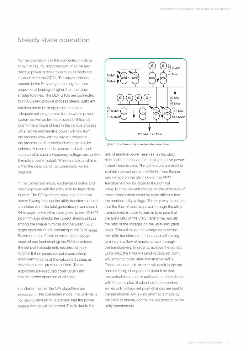
Normal.operation.is.in.the.connected.mode.as.
shown.in.Fig..12..Import/export.of.active.and.
reactive.power.is.close.to.zero.so.all.loads.are.
supplied.from.the.GTGs..The.larger.turbines.
operate.in.the.DLN.range.meaning.that.their.
proportional.loading.is.higher.than.the.other.
smaller.turbines..The.DLN.GTGs.are.connected..
to.HRSGs.and.provide.process.steam...Sufficient.
turbines.are.to.be.in.operation.to.ensure.
adequate.spinning.reserve.for.the.whole.power.
system.as.well.as.for.the.process.unit.islands...
Due.to.the.amount.of.load.in.the.various.process.
units,.active.and.reactive.power.will.flow.from..
the.process.area.with.the.larger.turbines.to..
the.process.loads.associated.with.the.smaller.
turbines..A.dead.band.is.associated.with.each.
state.variable.such.a.frequency,.voltage,.and.active
.&.reactive.power.output..When.a.state.variable.is
.within.the.dead.band,.no.corrections.. .will.be.
required.
In.the.connected.mode,.exchange.of.active.and.
reactive.power.with.the.utility.is.to.be.kept.close.
to.zero..The.P/f.algorithm.measures.the.active.
power.flowing.through.the.utility.transformers.and.
calculates.what.the.total.generated€power. should.
be
.
in
.
order.to.keep.this .value.close .to .zero...The.P/f.
algorithm.also.checks.the.correct.sharing.of.load.
among.the.smaller.turbines.and.between.the.2.
larger.ones.which.are.operating.in.the.DLN.range..
Based
.
on.these.2.sets.of.values.(total.power.
required
.
and
.
load. sharing). the. PMS. calculates.
the
.
set.point.adjustments.required.for.each
.turbine. ..It.then.sends.set.point.corrections.
equivalent
.
to
.
50. %.of.the.calculated.values.as.
described
.
in
.
the
.
previous.section...These
.algorithms.are.executed.continuously
.
and
.
ensure
.
correct
.
operation
.
at
.
all
.
times.
.In.a.similar.manner.the.Q/V.algorithms.are.
executed..In.the.connected.mode,.the.utility.tie.is.
not
.
strong .enough.to.guarantee.that.the.power.
system
.
voltage
.
will
.
be
.
correct.
0 MW + 0 Mvar
G G 2x71.5 MW+46 Mvar
G G G G
2x28.8 MW+16.5 Mvar
80 MW+55 Mvar
120 MW + 70 Mvar
2x31.5 MW+18.5 Mvar
Figure 12 – Case study steady-state power flow
This
.
is
.
due
.
to
.
the
.
lack.of.reactive.power.reserves.on.the.utility.side.and.is.the.reason.for.keeping.reactive.power.
import.close.to.zero..The.generators.are.used.to.
maintain.correct.system.voltages..
.
Thus.the.per.
unit.voltage.on.the.plant.side.of.the.utility
.transformers.will.be.close.to.the.nominal.
value,.but.the.per-unit.voltage.on.the.utility.side.of.
these.transformers.could.be.quite.different.from.
the.nominal.utility.voltage..The.only.way.to.ensure.
that.the.flow.of.reactive.power.through.the.utility.
transformers.is.close.to.zero.is.to.ensure.that..
the.turns.ratio.of.the.utility.transformer.equals..
the.ratio.of.the.voltages.on.the.utility.and.plant.
sides..This.will.cause.the.voltage.drop.across..
the.utility.transformers.to.be.very.small.leading..
to.a.very.low.flow.of.reactive.power.through..
the.transformers..In.order.to.achieve.the.correct.
turns.ratio,.the.PMS.will.send.voltage.set.point.
adjustments.to.the.utility.transformer.AVRs...
These.set.point.adjustments.will.result.in.the.tap.
position.being.changed.until.such.time.that..
the.correct.turns.ratio.is.achieved..In.accordance.
with.the.principles.of.robust.control.described.
earlier,.only.voltage.set.point.changes.are.sent.to.
the.transformer.AVRs.–.no.attempt.is.made.by..
the.PMS.to.directly.control.the.tap.position.of.the.
utility.transformers.
of€Emissions€by OptimaI.use.of.Gas.Turbines.Reduction

COM-POWER-WP0�EN Rev1 | 1�
It.is.also.necessary.to.ensure.correct.voltage.
throughout.the.plant..For.load.busbars.supplied.
only.via.step-down.transformers.(not.shown.in.
Fig..11),.this.is.achieved.by.the.transformer.AVRs.
without.any.assistance.from.the.PMS...For. load
.busbars.that.are.also.supplied.by.GTGs..(the.33.
kV.bus.in.Fig..11),.it.is.necessary.to.ensure.that
.reactive.power. .provided.both.from..
the.generators,.and.from.the.step-down.
transformers .connected.to.the.same.busbar...
This.is.achieved.by.implementing.the.same
.voltage.droop.characteristic. in. the. transformer.
AVR
.
as.in.the.generator.AVRs..Should.the.busbar.
voltage.differ.from.the.nominal.value,. the. PMS.
will.send.voltage.set.point.changes.to.the.
transformer.AVR.and.reactive.power.output.
set.point.changes.to.the.generator.AVRs...Should.
insufficient.or.excessive.reactive.power.flow.
through.the.transformers,.the.PMS.will.make.
further.transformer.AVR.set.point.changes.to.
ensure.correct.flow.of.reactive.power.between.both.
process.units.
Load.shedding.calculations.are.made.for.each.
process.unit.individually.and.then.for.the.whole.
plant.in.both.the.connected.and.islanded.mode..
Load.shedding.tables.corresponding.to.every.
normative.incident.for.each. ..configuration ...
are
.
made.
.
Should
.
there.not.be.sufficient.spinning.
reserve.for.any.of.the.configurations,. the. PMS. will.
warn.the.operators. and.also.suggest.which.GTG.
should.be.started..
.If.there.is.too.much.spinning.reserve,.the.PMS.
will.also.warn.the.operator.and.will. .suggest .
which.GTG.should.be.stopped.
Seconds
130125120115110105100-4
0
4
8
12
16
MW step load
Figure 13 – Dynamic & static spinning reserve
The.fast.load.shedding.calculations.must.be.based.
on.the.dynamic.spinning.reserve.[2]..Thus.even.
though.there.is.sufficient.generation.capacity,.load.
shedding.may.be.required..Fig..13.shows.what.
often.happens.when.a.GTG.is.subjected.to.a.large.
load.step,.in.this.case.14.MW.for.a.90.MW.GTG..
Initially.the.governor.responds.by.opening..the.gas.
valve.which.results.in.a.very.quick.increase.in.
output
.
power..This.is.of.course.the.desired.result.
–.the.ideal.response.is.shown.in.Fig..13.with..
the.solid.line..The.increased.amount.of.gas,.
however,.increases.the.exhaust.gas.temperature .
until.such.time.as.sufficient.air. . .available..
The.opening.of.the.air.inlet.vanes.is,. however,.very.
slow.in.comparison.with.the.gas.valve...Thus.the.
exhaust.gas.temperature.will.initially.rise.and.the.
exhaust.gas.temperature.regulation.will.decrease.
the.flow.of.gas.until.the.air.inlet.vanes.have.
opened
.
sufficiently..This.explains.the.dip.in.
the.output.power.curve.shown.in.a.dotted.line...
The.dynamic.spinning.reserve.is.only.4.MW...
Full.power.is.available.only.after.20.seconds.
.
GTG dynamic response & fast load shedding
of€Emissions€by OptimaI.use.of.Gas.Turbines.Reduction
is
becomes
It.is.possible.however,.to.consider.2.types.of.
load.shedding..Some.process.loads.will.accept.
outages.of.several.tens.of.seconds.and.can.be.
restarted.afterwards.and.the.process.continues..
Other.process.loads.when.switched.off,.even.for.
a.very.short.period.of.time,.will.require.manual.
intervention.prior.to.restarting..Process.loads.
accepting.outages.could.be.shed.first,.and.then.
restarted.gradually,.at.about.the.same.rate.as..
the.opening.of.the.air.inlet.vanes..Loads.not.
accepting.outages.should.be.shed.only.if.
absolutely.necessary..In.this.manner.it.is.possible.

COM-POWER-WP0�EN Rev1 | 1�
to.make.use.of.the.“static”.spinning.reserve.as.
well.at.the.dynamic.spinning.reserve..It.requires,.
however,.categorizing.loads.based.on.acceptable.
outage.times.and.not.just.on.importance.as.is.
normally.done.when.defining.load.shedding.tables.
Sudden.islanding.of.a.process.unit.will.of.course.
have.consequences.for.that.process.unit...
The.consequences.can.often.be.limited.by..
the.use.of.fast.load.shedding..There.are.however .
also.consequences.for.the.other.process.unit.
when.the.other.one.is.islanded..If.the.process.unit.
associated.with.the.40.MW.GTGs.is.islanded,..
the.other.GTGs.will.suddenly.lose.much.of..
the.load..Primary.regulation.will.ensure.that..
the.GTGs. .reduce.their.power.output,.but.
the.main.problem.will.be.that.they.can.no.longer.
operate.in.the.DLN.region..It.is.important.that..
the.consequences.of.normative.incidents.be.
reviewed.for.all.parts.of.the.plant,.and.not.just..
the.part.most.directly.affected.
In.this.plant,.much.of.the.process.steam.is.
produced.from.HRSGs.associated.with..
the.larger.turbines..The.power.output.of.these.
GTGs.is.however.determined.by.electrical.and.
DLN.considerations,.and.not.by.process.steam.
requirements..This.would.also.be.the.case.should.
STGs.use.the.steam..Since.it.is.not.possible.to.
regulate.the.GTG.output.based.on.process.steam.
requirements,.it.is.necessary.to.fit.the.boilers.with.
auxiliary.burners.[3]..Thus,.steam.can.be.produced.
independently.of.the.operation.of.the.turbines..
This.decouples.the.steam.system.from.the.power.
system..Thus.the.PMS.can.define.the.required.
power.output.of.the.turbines.based.on.electrical.
considerations.only,.and.does.not.need.to.take.
into.account.steam.system.constraints..
Process Steam
of€Emissions€by OptimaI.use.of.Gas.Turbines.Reduction
Case Study Remarks
There.are.advantages.to.using.distributed.
generation..A.single,.large.contingency.cannot.
cause.a.total.loss.of.generation.and.thus.
production..Also.having.loads.close.to.generation
.
reduces.transmission.losses..The.down.side.is..
the.difficulty.in.correctly.controlling.the.power.
system,.especially.the.voltage.
Operation.of.some.GTGs.in.DLN.mode.will.result.
in.very.unequal.load.sharing..The.DLN.turbines.
will.generally.be.more.heavily.loaded.since.they.
must.operate.well.above.the.DLN.limit.to.ensure.
stable.firing..The.dynamic.response.of.the.turbines.
will.not.be.the.same.since.they.are.operating.at.
different.percentage.loads..In.some.cases.this.can.
lead.to.nuisance.tripping.after.a.contingency.has.
occurred. The.very.limited.dynamic. response.
capability.of. large.turbines.is.often.a.surprise..
Fast.load. shedding.must.be.triggered.even.
though.there
.
is.enough.generation.capacity.
on.paper...From
.
a.dynamic. spinning. reserve.
viewpoint,..it. is. better .to. have. more. smaller.
turbines.than.fewer
.
larger.ones.
The.use.of.DLN.turbines.has,.however,. .positive
.
points..
The.
emissions.
are.
greatly.
reduced.
and.
this.is.very.important.today.since.more.and.more.
regulations.are.coming.into.effect.on.this.subject..
As.shown.in.the.case.study,.the.effective.loading..
of.the.DLN.turbines.is.higher.than.the.non-DLN.turbines.since.they.must.operate.well.above.
the.DLN.limit..The.DLN.turbines.are.modern.
machines.which.have.a.higher.efficiency.than.
older.machines..Thus.operating.the.more.efficient.
turbines.at.a.higher.output.reduces.energy.consumption.and.CO2.emissions...This,.however,.
can .be.achieved.only .using.secondary.regulation.

COM-POWER-WP0�EN Rev1 | 1�
of€Emissions€by OptimaI.use.of.Gas.Turbines.Reduction
PMS implementation
A.Power.Management.System.is.an.integrated.set.
of.sensors,.actuators,.communication.devices.and.
networks,.control.logic.and.operator.interfaces.
.
The.purpose.of.the.PMS.is.to.provide.real-time.
control.of.the.industrial.power.system.by.means.of.
the.following.functions,.many.of.which.have.been.
discussed.in.the.sections.above:
monitor.the.power.system
remote.control.the. power.system.switching.
devices
control.power.system.frequency
control.utilization.voltages
ensure.good.power.quality
provide.immunity.to.power.system.disturbances
control.power.import.&.export.
••
•••••
Although.the.PMS.relies.heavily.on.Information.
Technology.to.perform.many.of.the.functions,.
the.conceptual.design.must.be.made.by.power.
system.engineers..Both.disciplines.must.work.
closely.together.to.design.a.PMS.that.meets
..the.requirements.
Fig..14.gives.a.very.general.overview.of.a.PMS...
It.shows.the.connections.to.the.electrical.
distribution.system.which.are.made.via.intelligent.
devices.and.communication.networks,.as.well.as.
hard-wired.digital.&.analog.signals..The.
operator
.
workstations . . . .The.
redundant.PLCs .required.for.power.
management. functions. . .including. their. interface.
to.the.governors. and. AVRs.. This. interface. shows.
the.use.of.incremental.set.point.changes,
.one.of.the.basic.principles.of.Robust.Control.
Description of a Power Management System (PMS)
provide€the interface.
are
G G
GGGG
Utility
PLC
I/O Rack
PLC
AVR
G
AVRGovernor
+- pow
er+- voltage
+- v
olta
ge
Figure 14 – PMS Overview
Data Integrity Validation
The.PMS.actuators.will.send.incremental.set-point.
changes.to.gas.turbine.governors.and.generator..
&.transformer.AVRs..These.set-point.changes.control.
the.system.frequency.and.voltage.and.thus.are.
very.important.for correct.power. system. operation..
All
.
decisions
.
made
.
by.the.PMS.are.based.on.the.
data
.
that
.
has
.
been
.
collected.from.the.various.
devices.connected.to..the. power. system.. It. is. thus.
very.important.that
.
only. valid. data. be. used.. Bad.
data.can.cause.the.PMS. to. send. incorrect. set-point.
changes.and.drive.the.power.system.to.an. abnormal
.operating.condition.
.

COM-POWER-WP0�EN Rev1 | 1�
.
One.of.the.most.important.functions.of..
the.PMS.is.Data.Integrity.Validation..This.consists.
of.a.number.of.measures.to.check.that.the.data.
being.used.is.coherent..Should.discrepancies.
occur,.an.alarm.will.be.set.and.the.PMS.functions.
which.depend.on.this.data.will.be.suspended..
until.the.discrepancies.have.been.eliminated...
The.philosophy.of.robust.control.ensures.
satisfactory.operation.of.the.power.system.without.
the.PMS...Data.Integrity.Validation.ensures.that.PMS
.will.not.execute.functions.based.on.corrupt. data.
.
of€Emissions€by OptimaI.use.of.Gas.Turbines.Reduction
These.are.the.most.common.functions.of..the
..PMS.and.consist.in.showing.the.operator..
.status.of.the.power.system.and.allowing.him.to.
open.and.close.circuit.breakers.and.thus.change.
the.power.system.configuration..Remote.control.is.
usually.from.a.central.control.point..All.operators.
have.their.own.user.name.and.password.and.only.
operators.who.have.the.correct.authorization.are.
allowed. to. execute. orders. of. any. kind. Any. time.
remote.control.is.implemented,.whether.by.the
.operator.or.from.the.PMS.itself,.redundant.
communication.systems.are.normally.required.
This.prevents.the.failure.of.any.single.device.from.
propagating.through.the.system.
Monitoring & Remote Control
Power€Management€functions
voltage
control the€frequency
€and €and provide immunity€to€power€system
disturbances. Data Integrity Validation is of at€mostimportance€for€these functions. These€are
.
..
automatically.executed.and.the.control.logic.is.
performed.by.Programmable.Logic.Controllers.
(PLCs)...The.PLCs.are.normally.provided. in.a.
hot-standby .configuration.in.order.to.be.able.to.execute.their.
.
functions.even.should.a.fault.occur.
in
.
one
.
device.
.
The.PLCs.are.connected.to.the.PMS.
communication.system.in.such.a.manner.as.to.
have.direct.access.to.the.information.needed.to.
implement.the.functions..The.PLC.outputs.are.
connected.directly.to.the.primary.regulation.control.
devices.
the
Operator.work.stations.provide.the.information.
necessary.to.the.operator.for.correct.control.of..
the.power.system..The.information.must.be.
organized.in.a.very.clear.manner.in.order.that.the.
operator
.
immediately
.
sees. what.is.important.and.
what.needs.his.attention.. Generally. there. is. a.
main
.
PMS.operator.work.station.in.the
.
central
.control.room,.near..the.process.control
.work.stations. .The.main.work.station.normally.has
.dual.screens. allowing.permanent.visualization.
of
.
the
.
status
.
of
.
the.power.system.while.allowing.
the.operator.to.work.on.the.other.screen...Often.
there.are.local .PMS.work.stations.in.each.
substation,
.
these
.
work.stations. being. primarily.
used
.
when.
maintenance.work.is.being.carried.
out.

COM-POWER-WP0�EN Rev1 | 1�
of€Emissions€by OptimaI.use.of.Gas.Turbines.Reduction
Testing a PMS
The.testing.of.a.PMS.is.always.a.challenge.since.only.
part.of.the.system.can.be.tested.prior.to.installation.
at.site..During.the.Factory.Acceptance.Tests.(FAT),.
the.complete.PMS.communication.system,.all.
operator.work.stations,.all.PLCs.and.other.PMS.
devices.are.interconnected.and.powered..Interfaces.
to.the.power.system.devices.such.as.intelligent.relays
and.meters.are.simulated.in.order.to.demonstrate.
correct.communication..All.PMS.functions.are.tested
during.the.FAT.but.it.is.not.possible.to.demonstrate
that.all.performance.criteria.are.met.since.only.few.
of.the.many.devices.are.connected.
It.is.only.at.site,.after.the.PMS.has.been.installed
&.connected.that.the.compliance.with.the.PMS.
performance.criteria.can.be.demonstrated...
There.are.many.control.functions.in.the.PMS.and
each.control.function.depends.on.many.variables
and
.
dead
.
bands.
.
During
.
the
.
commissioning
.
these
variables.are.optimized.in.order.to.provide.the.best
performance.of.the.system..This.“fine.tuning”.is..
a.very.important.step.and.requires.access.to..
the.GTGs.during.commissioning,.something.that
is.often.difficult.to.obtain.
The.PMS.should.be.designed.to.allow.testing.at.
site.without.risk.to.the.power.equipment...
One.means.of.achieving.this.is.to.provide..
a.“gain”.for.each. function... When. the. gain. is.
0.%,.the.PMS.will.not.send.any control.
signals.but.the.commissioning.engineer.can
.check.that.the.signal.that.the.PMS.would.have
.sent.is.correct.or.not..After.validation.of.the.
function.at.0.%.gain,.the.gain.is.slowly.increased.
and.the.functions.checked..When.all.checking.
has.been.done.and.the.variables.and.dead.bands.
optimized,.the.gain.will.be.at.100.%.and.the.PMS.
fully operational.
Training
It.is.quite.difficult.to.provide.adequate.training.for.
PMS.operators.for.several.reasons..One.reason.
is.simply.the.fact.that.any.orders.sent.by.PMS.
operators.will.have.important.consequences.on.
the.operating.point.of.the.power.system...
Trainees.cannot.be.allowed.to.actually.execute.
orders..The.other.problem.is.that.a.well.designed.
robust.power.system.normally.operates.correctly.
for.long.periods.of.time.without.any.operator.
intervention..Some.functions.will.be.used.only.very.
infrequently...
When.operators.don’t.use.the.system.for.long.
periods.of.time,.they.often.forget.what.they.have.
to.do.
Training.of.new.operators,.and.repeat.training.
of.experienced.operators.can.best.be.done.by.
means.of.a.training.simulator.[4]...
The.training.simulator.has.the.same.operator.
interface.as.the.PMS.and.allows.the.operator.to.
execute.orders.and.see.their.consequences...
The.orders.are.simulated.–.they.are.not.really.
executed.on.the.power.system.

COM-POWER-WP0�EN Rev1 | �0
Conclusion
The.use.of.DLN.combustion.is.becoming.more.
common.due.to.stricter.regulations..The.additional.
constraints.that.it.brings.regarding.the.operation.
of.the.power.system.should.however,.not.be.
underestimated..It.is.necessary.to.carry.out.in.
depth.studies.and.simulations.of.all.possible.
operating.modes.of.the.power.system.in.order.to.
be.sure.that.the.loads.can.be.supplied.at.the.right.
frequency.and.voltage..This.is.especially.the.case.
when.there.are.turbines.having.different.operation.
modes.(DLN.and.standard).at.the.same.facility.
The.dynamic.response.of.the.turbines.should.be.
carefully.reviewed.with.the.turbine.supplier...
This.should.be.taken.into.account.in.defining..
the.number.and.rated.power.of.the.turbines.to.be.
purchased.for.the.plant.power.supply..Although.
there.are.economical.reasons.for.having.fewer,.
larger.turbines,.these.should.be.weighed.against.
the.costs.of.poor.power.system.performance.
When.STGs.are.used,.or.when.the.GTGs.are.
associated.with.HRSGs,.close.collaboration.
between.the.electrical.and.steam.system.
engineers.is.required..This.will.help.ensure.
that.each.system.is.capable.of.satisfying.the.
requirements.independent.of.the.operation..
of.the.other.system.
of€Emissions€by OptimaI.use.of.Gas.Turbines.Reduction

COM-POWER-WP0�EN Rev1 | �1
References
[1]..Nick.Hiscock,.Terence.Hazel,.Jonathan.
Hiscock;."Voltage.Regulation.at.Sites.with.
Distributed.Generation,".IAS.Transactions.on.
Industry.Applications,.Vol.44,.No..2,..
March-April.2008,.pp.445-453.
[2]..Roy.Hamilton,.John.Undrill,.Paul.Hamer,.Scott.
Manson,.“Considerations.for.Generation.
in.an.Islanded.Operation,”.Causes.of.Long.
Interruptions,.IEEE.PCIC.Conference.Record,.
2009.
[3]..Graeme.Peck,."Challenges.in.Using.Waste.Heat.
Recovery.and.DLE.Combustion.to.Reduce.
CO2.and.NOx.Emissions".in.PCIC.Europe.
Conference.Record,.2009.
[4]..Terence.Hazel,.Isabelle.Condamin,.Fabrice.
Audemard,.“Facilitating.Plant.Operation.&.
Maintenance.Using.an.Electrical.Network.
Monitoring.&.Control.System.Simulation.Tool”,.
IEEE.PCIC.Conference.Record,.2004.
Vita
Terence. Hazel. graduated. from. the. University. of.
Manitoba.Canada.with.a.BScEE.in.1970...
He.worked.for.one.year.as.a.power.coordination.
engineer.in.Perth.Australia.and.for.several.years.
in.Frankfurt.Germany.as.a.consulting.engineer.for.
construction.and.renovation.of.industrial.power.
distribution.systems..Since.1980.he.has.worked.
for.Schneider.Electric.(formerly.Merlin.Gerin).in.
their.projects.group.where.he.has.provided.team.
leadership.for.several.major.international.projects.
involving.process.control.and.power.distribution..
His.main.interests.are.in.power.quality,.and..
the.reliability.of.electrical.distribution.systems...
Mr..Hazel.is.a.senior.member.of.IEEE.and.is.author.
of.several.IEEE.papers.and.tutorials..He.is.also.
Secretary.and.Technical.Chair.of.the.Petroleum.&.
Chemical.Industry.Committee.Europe.which.holds.
an.annual.technical.conference..
(www.pcic-europe.eu)
of€Emissions€by OptimaI.use.of.Gas.Turbines.Reduction

Schneider Electric Industries SAS35,.rue.Joseph.MonierCS.30323F-.92506.Rueil.Malmaison.Cedex
RCS.Nanterre.954.503.439Capital.social.896.313.776.€www.schneider-electric.com
12-2009COM-POWER-WP04EN
©.2
009.
-.S
chne
ider
.Ele
ctric
.-.A
ll.rig
hts.
rese
rved
.
This document has been printed on ecological paper