REDUCING SOURCE CURRENT HARMONICS DUE …aircconline.com/ijci/V5N1/5116ijci05.pdfAndhra Pradesh,...
14
International Journal on Cybernetics & Informatics (IJCI) Vol. 5, No. 1, February 2016 DOI: 10.5121/ijci.2016.5105 45 REDUCING SOURCE CURRENT HARMONICS DUE TO BALANCED AND UN-BALANCED VOLTAGE VARIATION WITH FUZZY CONTROLLED D-STATCOM Mr. K. Ravi Sankar 1 , Mr. Dr.V. Kamaraju 2 and Mr. Dr. R. Srinivasa Rao 3 1 Assoc. Professor, Department of EEE, Coastal Institute of Technology and Management,Vizag, Andhra Pradesh, India. 2 Professor, Department of EEE, Mahaveer Institute of Science and Technology, Bandlaguda, Hyderabad, Telangana, India 3 Professor, Department of EEE, University College of Engineering, JNTUK, Kakinada, Andhra Pradesh ABSTRACT Electricity demand has been increasing due to the increase of population and industries. Hence it is very important to feed the demand with quality of generation. Improvement of power quality is the greater concern in advanced power system element, it is essential to congregate the need of energy by employ the renewable energy generating sources like pv, fuel cell, biomass, wind, etc and utilizing many more applications like grid interconnected systems, power quality improvement. The situations like harmonic, reactive power exchanging, power factor correction, balanced and un-balanced voltage variations & so on, due to greater effect on highly susceptible loads are to be encouraged in power distribution system. To enhance these circumstances, custom power appliances are used to achieve high grid voltage stability. In this paper, a voltage distortions controlled D-STATCOM based on fuzzy controller is a meticulous power appliance for enhancing harmonic distortions from high power semiconductor switching device, exchanging the both active & reactive power, defend the gird stability by implementing DG technology, to regulate the power quality issues in power distribution network. This paper implements the comparative analysis of PI and Fuzzy controlled DSTATCOM with energy backup scheme, controlled by pwm control technique and founded that fuzzy based IPQ theory for generation of reference current signals improves the power quality than PI based IPQ theory and this analysis is dynamically evaluated with Matlab/Simulink. KEYWORDS D-STATCOM, balanced-un-balanced voltage variations, fuzzy controller and Harmonics. 1. INTRODUCTION Renewable generation from wind and sun has enlarged considerably throughout past few years and forms a significance proportion of the whole generation within the grid. This renewable generation is focused in a very few states, to the extent that it can't be known as marginal generation and high thought must run to balance the variability of such generation. There’s a formidable programme for increase of such Renewable Generation and so, it's imperative to figure out how forward for facilitating massive scale integration of such variable Renewable Energy Sources (RES), keeping the protection of the grid. Moreover, as we tend to move towards a tighter frequency band, it becomes even more difficult to balance this variable RES. Generation
Transcript of REDUCING SOURCE CURRENT HARMONICS DUE …aircconline.com/ijci/V5N1/5116ijci05.pdfAndhra Pradesh,...

International Journal on Cybernetics & Informatics (IJCI) Vol. 5, No. 1, February 2016
DOI: 10.5121/ijci.2016.5105 45
REDUCING SOURCE CURRENT HARMONICS DUE TO
BALANCED AND UN-BALANCED VOLTAGE
VARIATION WITH FUZZY CONTROLLED D-STATCOM
Mr. K. Ravi Sankar
1, Mr. Dr.V. Kamaraju
2 and Mr. Dr. R. Srinivasa Rao
3
1Assoc. Professor, Department of EEE, Coastal Institute of Technology and Management,Vizag,
Andhra Pradesh, India. 2Professor, Department of EEE, Mahaveer Institute of Science and Technology,
Bandlaguda, Hyderabad, Telangana, India 3Professor, Department of EEE, University College of Engineering, JNTUK, Kakinada,
Andhra Pradesh
ABSTRACT Electricity demand has been increasing due to the increase of population and industries. Hence it is very
important to feed the demand with quality of generation. Improvement of power quality is the greater
concern in advanced power system element, it is essential to congregate the need of energy by employ the
renewable energy generating sources like pv, fuel cell, biomass, wind, etc and utilizing many more
applications like grid interconnected systems, power quality improvement. The situations like harmonic,
reactive power exchanging, power factor correction, balanced and un-balanced voltage variations & so on,
due to greater effect on highly susceptible loads are to be encouraged in power distribution system. To
enhance these circumstances, custom power appliances are used to achieve high grid voltage stability. In
this paper, a voltage distortions controlled D-STATCOM based on fuzzy controller is a meticulous power
appliance for enhancing harmonic distortions from high power semiconductor switching device,
exchanging the both active & reactive power, defend the gird stability by implementing DG technology, to
regulate the power quality issues in power distribution network. This paper implements the comparative
analysis of PI and Fuzzy controlled DSTATCOM with energy backup scheme, controlled by pwm control
technique and founded that fuzzy based IPQ theory for generation of reference current signals improves the
power quality than PI based IPQ theory and this analysis is dynamically evaluated with Matlab/Simulink.
KEYWORDS D-STATCOM, balanced-un-balanced voltage variations, fuzzy controller and Harmonics.
1. INTRODUCTION
Renewable generation from wind and sun has enlarged considerably throughout past few years
and forms a significance proportion of the whole generation within the grid. This renewable
generation is focused in a very few states, to the extent that it can't be known as marginal
generation and high thought must run to balance the variability of such generation. There’s a
formidable programme for increase of such Renewable Generation and so, it's imperative to
figure out how forward for facilitating massive scale integration of such variable Renewable
Energy Sources (RES), keeping the protection of the grid. Moreover, as we tend to move towards
a tighter frequency band, it becomes even more difficult to balance this variable RES. Generation

International Journal on Cybernetics & Informatics (IJCI) Vol. 5, No. 1, February 2016
46
from RE Sources depends on nature, i.e. wind rate and sunshine. The variability of RES power
will be self-addressed through improved statement techniques that are still evolving. Once the
proportion of RES becomes important, special attention must be paid to accurately forecast their
output. The changes in RES might affect the electrical network. There has been excessive traction
of non-sinusoidal current and voltage in electrical network, due to excessive usage of non-linear
masses. Power quality could also be marked in synchronous and non- synchronized phenomena
and this will result into visiting synchrononised with ac wave at power frequency.
A group of controllers along known as Custom Power Devices (CPD), that embody the
DSTATCOM (distribution static compensator), The DSTATCOM, a shunt connected device will
take care of the quality issues in the current it contains a de electrical condenser. Three phase
electrical converter module ac filter ,coupling electrical device and an impression strategy the
electronic block of D-STATCOM is the voltage sourced electrical converter, which converters an
input dc voltage into three phase output voltage in harmonic. The D-STATCOM puts electrical
convert, convert the dc-link voltage Vdc on electrical condenser. It can be presumed D-
STATCOM may be treated as voltage control supply.
The proposed fuzzy based instant power theory is valid for pure sin or non-sinusoidal and
balanced or unbalanced power systems and were later planned [4-8].The part of the output
voltage of the thyristor-based electrical converter, Vi, is controlled within the same approach
because the distribution system voltage, Vs. The proposed DSTATCOM relies on the fuzzy based
instant power theory; it provides smart compensation characteristics in steady state furthermore as
transient states compared to Proportional Integral (PI) based IPT Controller [9]. The FUZZY
based instant power theory generates the reference currents needed to compensate the distorted
line current harmonics and reactive power accurately when compared to the PI controller since it
reduces both error and change in error and also large variation in errors. Hence the proposed
concept has been analyzed with FUZZY controlled IPT and compared its advantages with the PI
controlled IPT.
2. PRINCIPAL OF THE D-STATCOM
The D-STATCOM is that the solid-state-based power device version of the SVC. The construct
of the D-STATCOM was planned by Gyugyi in 1976. In operation as a shunt-connected SVC, its
electrical phenomenon or inductive output currents is controlled severally from its connected AC
bus voltage. Attributable to the fast-switching characteristic of power converters, the D-
STATCOM provides a lot of quicker response as compared to the SVC.
The shunt compensator will live the PCC voltages and within reference current generations
algorithms with none drawback as these voltages area unit pure sinusoids. This may not be
attainable in actual systems where the masses area with at top of the feeder.
The PCC voltage is distorted by the switch frequency harmonics generated by D-STATCOM.
There will be switch and resistive loss within the D-STACOM circuit. These losses should be
proved by the system. We have a tendency to should so fitly modify the reference current
generation rule to accommodate of these factors. Finally, to supply a path for the harmonic
current generated by the CMLI primarily based VSI realizing the D-STATCOM to flow; we have
a tendency to should place further filters within the circuit.
In addition, within the event of a fast amendment in system voltage, the electrical condenser
voltage doesn't amendment instantaneously; thus, the D-STATCOM effectively reacts for the
specified responses. As an example, if the system voltage drops for any reason, there's an
inclination for the D-STATCOM to inject electrical phenomenon power to support the unfit

International Journal on Cybernetics & Informatics (IJCI) Vol. 5, No. 1, February 2016
47
voltages. On paper, the ability device used within the D-STATCOM is either a VSC or a current-
source device (CSC). In observe, however, the VSC is most popular owing to the bidirectional
voltage-blocking capability needed by the ability semiconductor devices utilized in CSCs. to
realize this type switch characteristic, an extra diode should be connected nonparallel with a
standard semiconductor switch, instead the organic structure of the semiconductor should be
changed. Each of those alternatives increase the physical phenomenon losses and total system
value. In general, a CSC derives its terminal power from a current supply, i.e., a reactor. As
compared, a charged reactor is way lousier than a charged electrical condenser. Moreover, the
VSC needs a current-source filter at its AC terminals that is of course provided by the coupling
electrical device outpouring inductance, whereas extra electrical condenser banks square measure
required at the AC terminals of the CSC. Finally, the VSCs will operate with higher potency than
the CSCs waste high-energy applications.
A suitable VSC is chosen supported the subsequent considerations: the voltage rating of the
facility network, this harmonic demand, the system complexness, etc. Basically, the D-
STATCOM system is comprised of 3 main parts: a VSC, a group of coupling reactors or a
transformer, and a controller. The inductances of the increased power transformers will act as
coupling reactors, while at a very high voltage system. The very purpose of the coupling
inductors is to strain these elements, that square measure generated primarily by the output
voltage facility. The voltage quality downside may be a concern, wherever the D-STASTCOM is
connected to the facility at PCC. Voltages, currents and square measure fed into controller to
compare with commands.
Za
Zb
Zc
Linear load Dstatcom
Control circuit
Cdc
Gate pulse
Three phase
Source
L
Non linear load
Fig.1.Basic Block Diagram of IPT Controlled DSTATCOM with Reactive and Harmonic Loads
The control performs as feedback control and brings a collection of changes consequently. The
diagram illustration of the D-STATCOM system with non-linear load is illustrated in Fig.1. The
VSC is described as a perfect supply related to internal loss that connected to the ac power via
coupling reactors. The exchange of the real power and reactive power between d-statcom and
additional able area unit typically controlled by the amplitude sections of the output voltage.
Within the case of a perfect lossless power convertor, the output voltage of the convertor is
controlled to be in section thereupon of the ability system. During this case, there's no real power
circulated within the D-STATCOM; so, a true power supply isn't required. To work the D-
STATCOM in electrical phenomenon mode or volt-ampere generation, +Q, the magnitude of the

International Journal on Cybernetics & Informatics (IJCI) Vol. 5, No. 1, February 2016
48
convertor output voltage is controlled to be larger than the voltage at the PCC. In distinction, the
magnitude of the output voltage of the convertor is controlled to be but that of the ability system
at the PCC on order to soak up reactive power or to work the D-STATCOM in inductive mode, -
Q. However, in observe, the convertor is related to internal losses caused by non-ideal power
semiconductor devices and passive elements. As a result, with none correct controls, the
condenser voltage are going to be discharged to compensate these losses, and can constantly
decrease in magnitude. To regulate the condenser voltage, very low phase shift δ is introduced
between the device voltage and therefore the installation voltage.
Fig .2. Phasor Diagram for Power Exchanges in Four Quadrants of DSTATCOM
A small lag of the device voltage with relevance the voltage at the PCC causes real power to
ensue the ability system to the D-STATCOM, whereas the active power is transferred from the D-
STATCOM to the ability system by dominant the device voltage in order that it leads the voltage
at the PCC. Fig .2. illustrates phasor diagrams of the voltage at the PCC, device output current
and voltage all told four quadrants of the PQ plane.
3. CONTROL STRATEGY From the very beginning of the electrical distribution system, voltage regulation, reactive power
burden and unbalanced loading of the phases are major problems faced by the power engineers.
With the advent of custom power devices and FACTS technology, the concept of DSTATCOM
has appeared which has served the purpose of dynamic reactive power compensation. With a few
modifications, DSATACOM can also be used for neutral current compensation, load balancing
and voltage regulation.
For reactive power compensation, DSTATCOM provides reactive power as required by the load
and thus the supply current remains at unity power issue (UPF). Since solely real power is being
provided by the supply, load equalization is achieved by creating the supply reference current
balanced.
Control strategy plays an important role in overall performance of the compensating device. The
management of a compensating device is completed in 3 stages. Within the 1st stage, the essential
voltage and current signals area unit detected power transformers (PT's), CT's, Hall-effect
sensors, and isolation amplifiers to assemble correct system info. Within the second stage,
compensating commands in terms of current or voltage levels area unit derived supported
completely different management ways and device configurations. Within the third stage of
management, the gating signals for the solid-state devices of the compensating devices area unit
International Journal on Cybernetics & Informatics (IJCI) Vol. 5, No. 1, February 2016
49
generated either in open loop or closed-loop system. Among the foremost in style schemes area
unit PWM, whereas for closed-loop system, unipolar pulse breadth modulation management
technique is that the most typical kind of pursuit management for CMLI based mostly shunt
compensators.
There are unit several management approaches offered for the generation of reference supply
currents for the management of VSC of DSTATCOM for three-phase, three-wire system within
the literature viz.
1. Instantaneous Power Theory ( IP Theory),
2. Synchronous Reference Frame (SRF) Theory,
3. Id-Iq Theory,
4. Modified Id-Iq Theory.
5.
Among the different control techniques applied to three-phase three-wire compensators, the SRF
based technique is found to be suitable for different topologies of DSTATCOM. The IRP theory
is simple and proven to be one of the best performances under various operating conditions and
hence this theory is used for the control of proposed H-bridge DSTATCOM.
3.1. Proposed Instantaneous Power Theory (IPT)
IP theory was primarily planned by Akagi. This theory relies on the transformation of 3 section
quantities to 2 section quantities in α-β frame and also the calculation of instant active and
reactive power during this frame. A basic diagram of this theory is shown in fig.3. detected inputs
are fed to the controller, and these quantities ar processed to
come up with reference current commands , , ), that are fed to a pulse dimension
modulation (PWM) signal generator to come up with final shift signals fed to the D-STATCOM;
Hence this block control the D-Statcom.
The source voltages can be given as:
(1)
Load currents of the system given as:
(2)
In 3 phase coordinates, a, b, and c axes are fixed on the same plane, with the phase difference by
2π/3. The instantaneous space vectors va and iLa are set on the “a” axis, and their amplitude
varies in positive and negative directions with time. This is true for the other two phases also. By
using Park’s transformation can be transformed to these phases.

International Journal on Cybernetics & Informatics (IJCI) Vol. 5, No. 1, February 2016
50
P
Q
HPF
abcabc
α,β
abcα,β
PI
VLabc
ILabc
α,β
V
I
V
I
abc
α,β
Iabcref
P
Q
Vdcref
Vdcact
Ploss
P
Q
Fig .3. Block Diagram of Proposed Control Strategy- Instantaneous Power Theory
(3)
(4)
Where α and β axes are the orthogonal coordinates. Conventional instantaneous power for three-
phase circuit can be defined as
(5)
Where p is equal to conventional equation
(6)
Hence the IRP can be given as
(7)
Therefore, in matrix form, instantaneous real and reactive power are given as
(8)
The α-β currents can be obtained as
(9)
Where
(10)
Instantaneous active and reactive powers and can be decomposed into an average (dc) and an
oscillatory component.
(11)
Where and are the average (dc) part and and are the oscillatory (ac) part of these real and
reactive instantaneous powers. Reference source currents are calculated to compensate the
International Journal on Cybernetics & Informatics (IJCI) Vol. 5, No. 1, February 2016
51
reactive power and the oscillatory component of the instantaneous active power. Therefore, the
reference source currents and in α-β coordinate are expressed as
(12)
Theses currents can be transformed in a-b-c quantities to find the reference currents in a-b-c
coordinates using inverse transformation.
(13)
Where is the zero sequence components, which is zero in three- phase three wire system.
The generated reference currents are compared with actual currents by using Hysteresis current
controller for generation of pulses.
Hysteresis
control
Iabcref Gate pulse to
D-statcomIabcact
Fig .4. Generation of Gating pulses
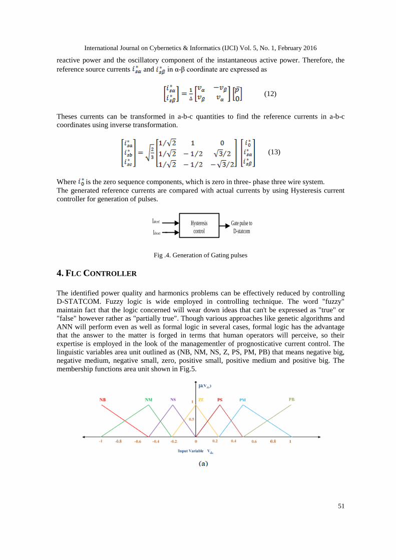
4. FLC CONTROLLER
The identified power quality and harmonics problems can be effectively reduced by controlling
D-STATCOM. Fuzzy logic is wide employed in controlling technique. The word "fuzzy"
maintain fact that the logic concerned will wear down ideas that can't be expressed as "true" or
"false" however rather as "partially true". Though various approaches like genetic algorithms and
ANN will perform even as well as formal logic in several cases, formal logic has the advantage
that the answer to the matter is forged in terms that human operators will perceive, so their
expertise is employed in the look of the managementler of prognosticative current control. The
linguistic variables area unit outlined as (NB, NM, NS, Z, PS, PM, PB) that means negative big,
negative medium, negative small, zero, positive small, positive medium and positive big. The
membership functions area unit shown in Fig.5.

International Journal on Cybernetics & Informatics (IJCI) Vol. 5, No. 1, February 2016
52
Fig.5. (a) Input ANF normalized membership function; (b) Input Vdc-ref Normalized Membership
Function; (c) Output Imax Normalized Membership Function.
Table 1. The Membership functions for FLC
E CE
NB NM NS Z PS PM PB
PB Z PS PM PB PB PB PB
PM NS Z PS PM PB PB PB
PS NM NS Z PS PM PB PB
Z NB NM NS Z PS PM PB
NS NB NB NM NS Z PS PM
NM NB NB NM NM NS Z PS
NB NB NB NB NB NM NS Z
From the table I, each error and its change in error is divided into 7 X 7 membership functions as:
Negative Big (NB), Negative Medium (NM), Negative Small (NS), Zero (Z), Positive Small (PS),
Positive Medium (PM) and Positive Big (PB).
5. MATLAB/SIMULINK ANALYSIS
Here simulation is carried out in different cases.
1). Performance of D-Statcom at Balanced Sinusoidal Source Voltage.
2). Performance of D-Statcom at Balanced Non-Sinusoidal Source Voltage.
3). Performance of D-Statcom at Un-Balanced Sinusoidal Source Voltage.

International Journal on Cybernetics & Informatics (IJCI) Vol. 5, No. 1, February 2016
53
4). Performance of PI Controlled D-Statcom at Un-Balanced Non-Sinusoidal Source Voltage.
5). Performance of FUZZY Controlled D-Statcom at Un-Balanced Non-Sinusoidal Source
Voltage.
Case I: Performance of D-Statcom at Balanced Sinusoidal Source Voltage.
Fig.6. Simulink model of D-Statcom at Balanced Sinusoidal Source Voltage
Fig.6. Shows The Matlab/Simulink Model Of Power System Network With D-Statcom At
Balanced Sinusoidal Source Voltage.
Fig.7. Simulated output wave forms of Source voltage, Source, Load and Compensation Current.
Fig.7. Shows The Simulated Output Wave Forms Of The Source Voltage And Source Current,
Load Current And Compensation Current At Balanced Sinusoidal Source Voltage.
International Journal on Cybernetics & Informatics (IJCI) Vol. 5, No. 1, February 2016
54
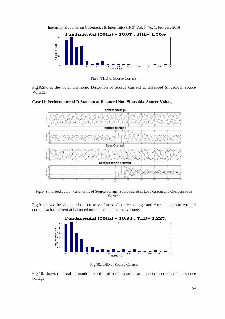
Fig.8. THD of Source Current.
Fig.8.Shows the Total Harmonic Distortion of Source Current at Balanced Sinusoidal Source
Voltage.
Case II: Performance of D-Statcom at Balanced Non-Sinusoidal Source Voltage.
Fig.9. Simulated output wave forms of Source voltage, Source current, Load current and Compensation
Current
Fig.9. shows the simulated output wave forms of source voltage and current load current and
compensation current at balanced non-sinusoidal source voltage.
Fig.10. THD of Source Current
Fig.10. shows the total harmonic distortion of source current at balanced non- sinusoidal source
voltage.

International Journal on Cybernetics & Informatics (IJCI) Vol. 5, No. 1, February 2016
55
Case III: Performance of D-Statcom at Un-Balanced Sinusoidal Source Voltage.
Fig.11. Simulink model of D-Statcom at Un-Balanced Sinusoidal Source Voltage
Fig.11. shows the Matlab/Simulink model of power system network with D-STATCOM at un-
balanced sinusoidal source voltage.
Fig.12. Simulated output wave forms of Source voltage, Source current, Load current and Compensation
Current
Fig.12. shows the output wave forms of source voltage and current, load current and
compensation current at un-balanced sinusoidal source voltage.
Fig.13.THD of Source Current

International Journal on Cybernetics & Informatics (IJCI) Vol. 5, No. 1, February 2016
56
Fig.13. shows the total harmonic distortion of source current at un-balanced sinusoidal source
voltage shows 3.79%.
Case IV: Performance of PI Controlled D-Statcom at Un-Balanced Non-Sinusoidal Source
Voltage.
Fig.14. Simulated output wave forms of Source voltage, Source current, Load current and Compensation
Current
Fig.14. shows the output wave form of source voltage and current, load current and compensation
current at un-balanced non-sinusoidal source voltage with PI Controller.
Fig.15. THD of Source Current
Fig.15.shows the total harmonic distortions of source current at un-balanced non-sinusoidal
source voltage with PI Controller

International Journal on Cybernetics & Informatics (IJCI) Vol. 5, No. 1, February 2016
57
Case V: Performance of FUZZY controlled D-Statcom at Un-Balanced Non-Sinusoidal
Source Voltage.
Fig.16. Simulated output wave forms of Source voltage, Source current, Load current and Compensation
Fig.16. shows the output wave form of source voltage and current, load current and compensation
current at un-balanced non-sinusoidal source voltage under FUZZY controlled D-Statcom.
Fig.17. THD of Source Current
Fig.17.Shows the Total Harmonic Distortion of Source Current at Un-Balanced Non-Sinusoidal
Source Voltage with Fuzzy Controlled D-Statcom.
6. CONCLUSION
In this paper, the renewable sources interconnection with the main supply can influence the power
quality at the point of common coupling and can pollute the electrical network with Balanced
Sinusoidal and Un-Balanced Non-Sinusoidal voltage distortions and harmonic components which
International Journal on Cybernetics & Informatics (IJCI) Vol. 5, No. 1, February 2016
58
exceed the stipulated limits. The proposed fuzzy based D-Statcom is employed to compensate the
harmonics and reactive current caused due to the Balanced Sinusoidal and Un-Balanced Non-
Sinusoidal voltage distortions and non-linear load in distribution system. From the simulation
analysis the source current harmonics has been reduced to 1.5% with FUZZY based IPT
controlled DSTATCOM but the PI based IPT controlled DSTATCOM only reduces up to 3.41%.
Hence it has been proven that fuzzy based IPT controller is suitable for enhancing the power
quality at Balanced and Un-Balanced Voltage Variations.
REFERENCES
[1] A.E. Hammad, Comparing the Voltage source capability of Present and future Var Compensation
Techniques in Transmission System, IEEE Trans, on Power Delivery. Volume 1. No.1 Jan 1995.
[2] G.Yalienkaya, M.H.J Bollen, P.A. Crossley, “Characterization of Voltage Sags in Industrial
Distribution System”, IEEE transactions on industry applications, volume 34, No. 4, July/August,
PP.682-688, 1999.
[3] Haque, M.H., “Compensation of Distribution Systems Voltage sags by DVR and D-STATCOM”,
Power Tech Proceedings, 2001 IEEE Porto, Volume 1, PP.10-13, September 2001.
[4] Anaya-Lara O, Acha E., “Modeling and Analysis Of Custom Power Systems by PSCAD/EMTDC”,
IEEE Transactions on Power Delivery, Volume 17, Issue: 2002, Pages: 266-272.
[5] Bollen, M.H.J.,”Voltage sags in Three Phase Systems”, Power Engineering Review, IEEE, Volume
21, Issue: 9, September 2001, PP: 11-15.
[6] M.Madrigal, E.Acha. “Modeling of Custom Power Equipment Using Harmonics Domain
Techniques”, IEEE 2000.
[7] R.Meinski, R.Pawelek and I.Wasiak, “Shunt Compensation For Power Quality Improvement Using a
D-STATCOM controller Modelling and Simulation”, IEEE Proce, Volume 151, No. 2, March 2004.
[8] J.Nastran , R. Cajhen, M. Seliger, and P.Jereb,”Active Power Filters for Nonlinear AC loads, IEEE
Trans.on Power Electronics Volume 9, No.1, PP: 92-96, Jan 2004.
[9] L.A.Moran, J.W. Dixon, and R.Wallace, A Three Phase Active Power Filter with fixed Switching
Frequency For Reactive Power and Current Harmonics Compensation, IEEE Trans. On Industrial
Electronics. Volume 42, PP:402-8, August 1995.