Reduced-order Modeling of Reacting Supersonic Flows in...
29
Scramjet Nozzle Model Dalle, Torrez, Driscoll Vehicle Model Motivation MASIV Code Aerodynamic Model Flow Model Gas Model Scramjet Nozzle 1D Comparison 2D Comparison Conclusions Appendix Programs Performance References Reduced-order Modeling of Reacting Supersonic Flows in Scramjet Nozzles 46th AIAA/ASME/SAE/ASEE Joint Propulsion Conference & Exhibit Derek J. Dalle, Sean M. Torrez, James F. Driscoll October 17, 2010 CC C S Scramjet Nozzle Model, JPC 2010 1/29
Transcript of Reduced-order Modeling of Reacting Supersonic Flows in...

Scramjet NozzleModel
Dalle, Torrez,Driscoll
Vehicle ModelMotivation
MASIV Code
AerodynamicModelFlow Model
Gas Model
Scramjet Nozzle1D Comparison
2D Comparison
Conclusions
AppendixPrograms
Performance
References
Reduced-order Modeling ofReacting Supersonic Flows in
Scramjet Nozzles46th AIAA/ASME/SAE/ASEE Joint Propulsion
Conference & Exhibit
Derek J. Dalle, Sean M. Torrez, James F. Driscoll
October 17, 2010
CCCS
Scramjet Nozzle Model, JPC 2010 1/29
Scramjet NozzleModel
Dalle, Torrez,Driscoll
Vehicle ModelMotivation
MASIV Code
AerodynamicModelFlow Model
Gas Model
Scramjet Nozzle1D Comparison
2D Comparison
Conclusions
AppendixPrograms
Performance
References
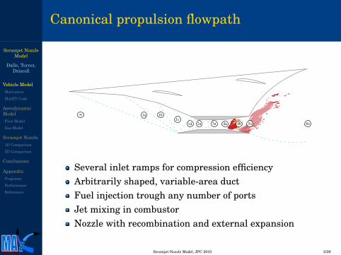
Canonical propulsion flowpath
8 1a 1b1c
1d 2a 3a 4a 4b 5a 6a
Several inlet ramps for compression efficiencyArbitrarily shaped, variable-area ductFuel injection trough any number of portsJet mixing in combustorNozzle with recombination and external expansion
CCCS
Scramjet Nozzle Model, JPC 2010 2/29

Scramjet NozzleModel
Dalle, Torrez,Driscoll
Vehicle ModelMotivation
MASIV Code
AerodynamicModelFlow Model
Gas Model
Scramjet Nozzle1D Comparison
2D Comparison
Conclusions
AppendixPrograms
Performance
References
Integration with hypersonic vehicle
Three-dimensional vehicle with triangular panels
Propulsion flowpath modeled as two-dimensional
Vogel, J. M., Kelkar, A. G., Inger, G., Whitmer, C., Sidlinger, A., andRodriguez, A., “Control-Relevant Modeling of Hypersonic Vehicles,” 2009American Control Conference.
CCCS
Scramjet Nozzle Model, JPC 2010 3/29
Scramjet NozzleModel
Dalle, Torrez,Driscoll
Vehicle ModelMotivation
MASIV Code
AerodynamicModelFlow Model
Gas Model
Scramjet Nozzle1D Comparison
2D Comparison
Conclusions
AppendixPrograms
Performance
References
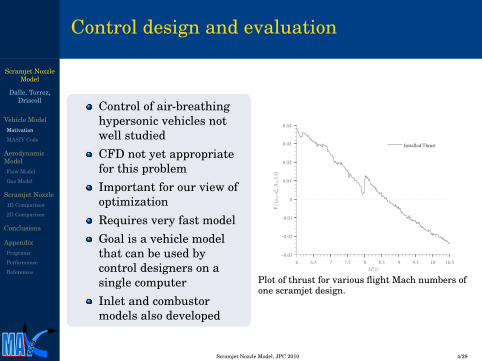
Control design and evaluation
Control of air-breathinghypersonic vehicles notwell studiedCFD not yet appropriatefor this problemImportant for our view ofoptimizationRequires very fast modelGoal is a vehicle modelthat can be used bycontrol designers on asingle computerInlet and combustormodels also developed
6 6.5 7 7.5 8 8.5 9 9.5 10 10.5−0.03
−0.02
−0.01
0
0.01
0.02
0.03
0.04
M[1]F
/(ρin
u2 in
Ain
)[1]
Installed Thrust
Plot of thrust for various flight Mach numbers ofone scramjet design.
CCCS
Scramjet Nozzle Model, JPC 2010 4/29

Scramjet NozzleModel
Dalle, Torrez,Driscoll
Vehicle ModelMotivation
MASIV Code
AerodynamicModelFlow Model
Gas Model
Scramjet Nozzle1D Comparison
2D Comparison
Conclusions
AppendixPrograms
Performance
References
The Michigan/AFRL Scramjet In Vehicle code
InletWave interactions solved using exact solutionExpansions discretizedArbitrary number of distinct regions tracked
CombustorRealistic fuel-air mixing from jet lawsFinite-rate chemistry pre-tabulated from flamelet solutionsVariable fuel injection and duct area changeWill incorporate isolator to cover ram/scram transition
NozzleUses same aerodynamic model as inletUses conditions from combustor (can be non-uniform)Incorporates finite-rate chemistry
CCCS
Scramjet Nozzle Model, JPC 2010 5/29
Scramjet NozzleModel
Dalle, Torrez,Driscoll
Vehicle ModelMotivation
MASIV Code
AerodynamicModelFlow Model
Gas Model
Scramjet Nozzle1D Comparison
2D Comparison
Conclusions
AppendixPrograms
Performance
References
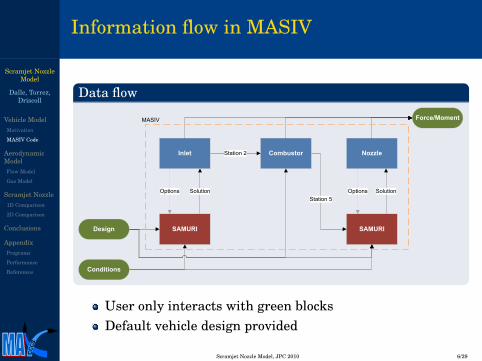
Information flow in MASIV
Data flow
Inlet Combustor Nozzle
SAMURI SAMURI
Force/Moment
Design
Conditions
SolutionOptions
Station 2
Options SolutionStation 5
MASIV
User only interacts with green blocksDefault vehicle design provided
CCCS
Scramjet Nozzle Model, JPC 2010 6/29

Scramjet NozzleModel
Dalle, Torrez,Driscoll
Vehicle ModelMotivation
MASIV Code
AerodynamicModelFlow Model
Gas Model
Scramjet Nozzle1D Comparison
2D Comparison
Conclusions
AppendixPrograms
Performance
References
Aerodynamic model (SAMURI)
Supersonic AerodynamicModel Using RiemannInteractions
Uses oblique shock theory
Discrete expansion waves
Arbitrary number of waveinteractions
Accounts for caloricallyimperfect gas
Any geometry with nodetached waves
Two diamond airfoils in M∞ = 2, α = 0 flow
Sample inlet geometry at M∞ = 8
CCCS
Scramjet Nozzle Model, JPC 2010 7/29

Scramjet NozzleModel
Dalle, Torrez,Driscoll
Vehicle ModelMotivation
MASIV Code
AerodynamicModelFlow Model
Gas Model
Scramjet Nozzle1D Comparison
2D Comparison
Conclusions
AppendixPrograms
Performance
References
Shock/expansion theory
Oblique shocksPerfect-gas obliqueshock analyticsolutiona
Cubic polynomial forsinβ where β is thewave angleThree solutions
Weak oblique shockStrong oblique shockEntropy-destroyingshock
aThompson, M. J. “A Note on theCalculation of Oblique Shock WaveCharacteristics.” Journal ofAerospace Sciences. 1950 vol. 27,pp. 741-744
control volume A
control volume B
Illustration of two control volumes around a diamond airfoil
Net fluxes into A must be the sameas net fluxes into BDrag is not a function of the controlvolume used to compute it
CCCS
Scramjet Nozzle Model, JPC 2010 8/29

Scramjet NozzleModel
Dalle, Torrez,Driscoll
Vehicle ModelMotivation
MASIV Code
AerodynamicModelFlow Model
Gas Model
Scramjet Nozzle1D Comparison
2D Comparison
Conclusions
AppendixPrograms
Performance
References
The case for expansion shocks
Discrete expansions
Finite-strength waves aredifferent from continuousexpansionsOne degree of freedom (waveangle) and three constraints(mass and momentumconservation)
Solution
Use downstream state forextra degrees of freedomLeads exactly to the obliqueshock conditionsStill accurate if expansionsare split into several shocks
Control volume
Control volume around an expansion withnexp = 1
Net mass/momentum fluxinto control volume must bezeroSame for any other controlvolume that does not crossthe surface
CCCS
Scramjet Nozzle Model, JPC 2010 9/29

Scramjet NozzleModel
Dalle, Torrez,Driscoll
Vehicle ModelMotivation
MASIV Code
AerodynamicModelFlow Model
Gas Model
Scramjet Nozzle1D Comparison
2D Comparison
Conclusions
AppendixPrograms
Performance
References
Discretized expansion waves
DiscretizationMakes conditions a piecewiseconstant function of angleUsing angles based on Guassianquadrature minimizes∫
σA
σB
(M(σ)− M̃(σ))2 dσ
Puts waves near edges of expansionGoal is to keep accuracy high andnexp low
ConservationUse expansion shocksEstimate of state B will be slightlyinaccurate
σ
A
B
Smooth expansion with δ = 18.4◦and M∞ = 1.5
Sample expansion with nexp = 4
CCCS
Scramjet Nozzle Model, JPC 2010 10/29
Scramjet NozzleModel
Dalle, Torrez,Driscoll
Vehicle ModelMotivation
MASIV Code
AerodynamicModelFlow Model
Gas Model
Scramjet Nozzle1D Comparison
2D Comparison
Conclusions
AppendixPrograms
Performance
References
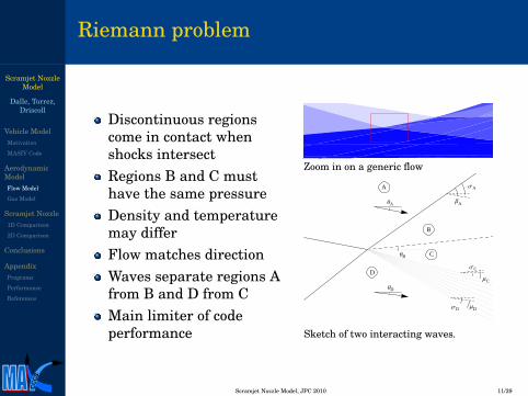
Riemann problem
Discontinuous regionscome in contact whenshocks intersectRegions B and C musthave the same pressureDensity and temperaturemay differFlow matches directionWaves separate regions Afrom B and D from CMain limiter of codeperformance
Zoom in on a generic flow
A
B
C
D
ΘB
ΘA
ΘD
ΣA
ΒA
ΣD
ΣC
ΜD
ΜC
Sketch of two interacting waves.
CCCS
Scramjet Nozzle Model, JPC 2010 11/29
Scramjet NozzleModel
Dalle, Torrez,Driscoll
Vehicle ModelMotivation
MASIV Code
AerodynamicModelFlow Model
Gas Model
Scramjet Nozzle1D Comparison
2D Comparison
Conclusions
AppendixPrograms
Performance
References
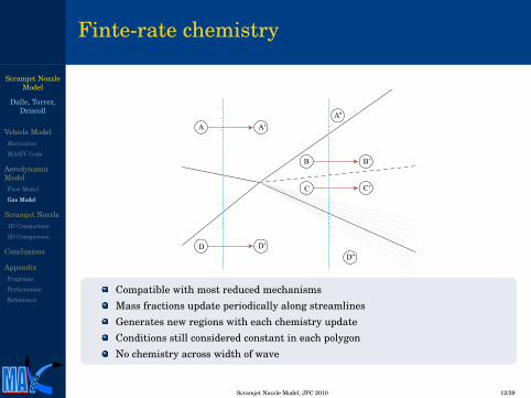
Finte-rate chemistry
A
B
C
D D′
A′
C′
B′
D′′
A′′
Compatible with most reduced mechanismsMass fractions update periodically along streamlinesGenerates new regions with each chemistry updateConditions still considered constant in each polygonNo chemistry across width of wave
CCCS
Scramjet Nozzle Model, JPC 2010 12/29

Scramjet NozzleModel
Dalle, Torrez,Driscoll
Vehicle ModelMotivation
MASIV Code
AerodynamicModelFlow Model
Gas Model
Scramjet Nozzle1D Comparison
2D Comparison
Conclusions
AppendixPrograms
Performance
References
Reduced chemical mechanism
Hydrogen-Air combustion mechanisma
33 one-way reactions and 14 species (including Argon)Program contains interpreter to use any mechanism
aJachimowski, C. J. “An analytic study of the Hydrogen-Air reaction mechanism with application to SCRAMJETcombustion.” NASA Technical Paper 2791, 1988
1 H2 +O2 → 2OH
2 H+O2 → OH+O
3 O+H2 → OH+H
4 OH+H2 → H2O+H
5 2OH→ H2O+O
6 H+OH+M→ H2O+M
7 2H+M→ H2 +M
8 H+O+M→ OH+M
9 H+O2 +M→ HO2 +M
10 HO2 +H→ H2 +O211 HO2 +H→ 2OH
12 HO2 +H→ H2O+O
13 HO2 +O→ O2 +OH
14 HO2 +OH→ H2O+O215 2HO2 → H2O2 +O216 H+H2O2 → H2 +HO217 O+H2O2 → OH+HO218 OH+H2O2 → H2O+HO219 H2O2 +M→ 2OH+M
20 2O+M→ O2 +M
21 2N+M→ N2 +M
22 N+O2 → NO+O
23 N+NO→ N2 +O
24 N+OH→ NO+H
25 N+NO+M→ HNO+M
26 H+HNO→ NO+H227 O+HNO→ NO+OH
28 OH+HNO→ NO+H2O
29 HO2 +HNO→ NO+H2O230 HO2 +NO→ NO2 +OH
31 H+NO2 → NO+OH
32 O+NO2 → NO+O233 NO2 +M→ NO+O+M
CCCS
Scramjet Nozzle Model, JPC 2010 13/29

Scramjet NozzleModel
Dalle, Torrez,Driscoll
Vehicle ModelMotivation
MASIV Code
AerodynamicModelFlow Model
Gas Model
Scramjet Nozzle1D Comparison
2D Comparison
Conclusions
AppendixPrograms
Performance
References
Nozzle geometry
Nozzle may have smooth surfacebut modeled as a series of flatramps hereSignificant expansion ratio andflow dominated by expansion fansLower exhaust plume boundaryaffected by freestream pressureand wave interactionsPotentially affected byrecombination of radical speciesfrom the combustorDifficult to define optimum buteasy to obtain good performance
H4
H5
H6
L5y
x
Sample scramjet nozzle geometry
Corresponding solution (temperature)
CCCS
Scramjet Nozzle Model, JPC 2010 14/29

Scramjet NozzleModel
Dalle, Torrez,Driscoll
Vehicle ModelMotivation
MASIV Code
AerodynamicModelFlow Model
Gas Model
Scramjet Nozzle1D Comparison
2D Comparison
Conclusions
AppendixPrograms
Performance
References
Geometry and boundary conditions
GeometryGeometry from last slideMostly external expansionExpansion ratio of 5Emphasizestwo-dimensional flow
ConditionsFlight Mach number of 1810% dissociationVery high exit velocitySelected to emphasizerecombination
Property Freestream Post-combustorρ 0.001966 kg/m3 0.002240 kg/m3
p 149.1 Pa 1094 PaT 264.2 K 1400 Ku 5865 m/s 5131 m/s
YN2 0.755590 0.734173YO2 0.231522 0YAr 0.012888 0.012523
YH2O 0 0.227974YH 0 0.001417
YOH 0 0.023913
CCCS
Scramjet Nozzle Model, JPC 2010 15/29

Scramjet NozzleModel
Dalle, Torrez,Driscoll
Vehicle ModelMotivation
MASIV Code
AerodynamicModelFlow Model
Gas Model
Scramjet Nozzle1D Comparison
2D Comparison
Conclusions
AppendixPrograms
Performance
References
Validation models
SAMURI with chemistryTwo-dimensional waveinteraction modelJachimawski chemicalmechanismInviscid solutionMost accuratereduced-order model
SAMURI without chemistryTwo-dimensional waveinteraction modelFrozen chemistryInviscid solutionFastest model
Two-dimensional CFDCommercial CFD++packageJachimawski chemicalmechanismViscous solutionApproximately 300,000cells
Quasi-1D modelFind plume usingSAMURIOne-dimensional solutionJachimawski mechanismInviscid solution
CCCS
Scramjet Nozzle Model, JPC 2010 16/29

Scramjet NozzleModel
Dalle, Torrez,Driscoll
Vehicle ModelMotivation
MASIV Code
AerodynamicModelFlow Model
Gas Model
Scramjet Nozzle1D Comparison
2D Comparison
Conclusions
AppendixPrograms
Performance
References
Exhaust plume
0 1 2 3 4 5
0.0
0.5
1.0
1.5
2.0
2.5
x [m]
y[m
]
Very similar plumeRecombination makes plume slightly biggerViscosity seems to not have a noticeable effect
CCCS
Scramjet Nozzle Model, JPC 2010 17/29
Scramjet NozzleModel
Dalle, Torrez,Driscoll
Vehicle ModelMotivation
MASIV Code
AerodynamicModelFlow Model
Gas Model
Scramjet Nozzle1D Comparison
2D Comparison
Conclusions
AppendixPrograms
Performance
References
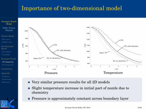
Importance of two-dimensional model
0 1 2 3 4 5
200
400
600
800
1000
x [m]
p[P
a]
Quasi-1D
CFD
2D, no chemistry
2D, with chemistry
Pressure
0 1 2 3 4 5
800
900
1000
1100
1200
1300
1400
x [m]
T[K
]
Quasi-1D
CFD
2D, no chemistry
2D, with chemistry
Temperature
Very similar pressure results for all 2D models
Slight temperature increase in initial part of nozzle due tochemistry
Pressure is approximately constant across boundary layer
CCCS
Scramjet Nozzle Model, JPC 2010 18/29

Scramjet NozzleModel
Dalle, Torrez,Driscoll
Vehicle ModelMotivation
MASIV Code
AerodynamicModelFlow Model
Gas Model
Scramjet Nozzle1D Comparison
2D Comparison
Conclusions
AppendixPrograms
Performance
References
Importance of boundary layer
Boundary layer has ahuge effect
Velocity isapproximately thesame as thrust
Chemistry has smalleffect
Very large kineticenergies compared torecombination heatrelease
0 1 2 3 4 5
5150
5200
5250
5300
5350
5400
5450
x [m]
u[m
/s]
Quasi-1D
CFD
2D, no chemistry
2D, with chemistry
Velocity plot
CCCS
Scramjet Nozzle Model, JPC 2010 19/29

Scramjet NozzleModel
Dalle, Torrez,Driscoll
Vehicle ModelMotivation
MASIV Code
AerodynamicModelFlow Model
Gas Model
Scramjet Nozzle1D Comparison
2D Comparison
Conclusions
AppendixPrograms
Performance
References
Mass fraction results
0 1 2 3 4 50.228
0.230
0.232
0.234
0.236
0.238
x [m]
Y H2O
Quasi-1D
CFD
2D, no chemistry
2D, with chemistry
YH2O plot
0 1 2 3 4 5
0.005
0.010
0.015
0.020
x [m]
Y OH
Quasi-1D
CFD
2D, no chemistry
2D, with chemistry
YOH plot
Approximately similar results
Something causes H2O to dissociate in CFD
Error in 2D model seems to be due to missing boundary layers
Accuracy of 1D model is likely a coincidence
CCCS
Scramjet Nozzle Model, JPC 2010 20/29

Scramjet NozzleModel
Dalle, Torrez,Driscoll
Vehicle ModelMotivation
MASIV Code
AerodynamicModelFlow Model
Gas Model
Scramjet Nozzle1D Comparison
2D Comparison
Conclusions
AppendixPrograms
Performance
References
2D temperature plots
CFD
1400
1000
400
400
18001400
1200
SAMURI
Maximum temperature 2700 K
Similar results in inviscid regions
Large boundary layer
Note shock wave starting at cowl trailing edge
CCCS
Scramjet Nozzle Model, JPC 2010 21/29
Scramjet NozzleModel
Dalle, Torrez,Driscoll
Vehicle ModelMotivation
MASIV Code
AerodynamicModelFlow Model
Gas Model
Scramjet Nozzle1D Comparison
2D Comparison
Conclusions
AppendixPrograms
Performance
References
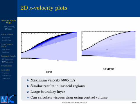
2D x-velocity plots
CFD
5500
5000
5700
5600
SAMURI
Maximum velocity 5865 m/s
Similar results in inviscid regions
Large boundary layer
Can calculate viscous drag using control volume
CCCS
Scramjet Nozzle Model, JPC 2010 22/29
Scramjet NozzleModel
Dalle, Torrez,Driscoll
Vehicle ModelMotivation
MASIV Code
AerodynamicModelFlow Model
Gas Model
Scramjet Nozzle1D Comparison
2D Comparison
Conclusions
AppendixPrograms
Performance
References
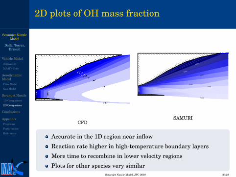
2D plots of OH mass fraction
CFD
0.002
0.022
0.022
0.0020.004
0.008
0.016
SAMURI
Accurate in the 1D region near inflow
Reaction rate higher in high-temperature boundary layers
More time to recombine in lower velocity regions
Plots for other species very similar
CCCS
Scramjet Nozzle Model, JPC 2010 23/29

Scramjet NozzleModel
Dalle, Torrez,Driscoll
Vehicle ModelMotivation
MASIV Code
AerodynamicModelFlow Model
Gas Model
Scramjet Nozzle1D Comparison
2D Comparison
Conclusions
AppendixPrograms
Performance
References
Conclusions
MASIV
SAMURI wave model able to analyze nozzles
Capable of analyzing finite-rate chemistry
Computational time less than one second
Nozzle flow physics
Viscosity very important
Has usual effects on temperature, velocity, and thrustAlso plays a role in recombination
Two-dimensional nature of flow more important than justdetermining the exhaust plume
Energy due to recombination small compared to kinetic energy
Recombination happens very quickly in most nozzles
CCCS
Scramjet Nozzle Model, JPC 2010 24/29

Scramjet NozzleModel
Dalle, Torrez,Driscoll
Vehicle ModelMotivation
MASIV Code
AerodynamicModelFlow Model
Gas Model
Scramjet Nozzle1D Comparison
2D Comparison
Conclusions
AppendixPrograms
Performance
References
Acknowledgments
MACCCS group, Scott G. V. Frendreis, Matt L. Fotia,Torstens Skujins, Nate Falkiewicz, Carlos E. S. CesnikAFRL/AFOSR, Michael W. Oppenheimer, MichaelA. Bolender, David B. DomanThis research was supported by U.S. Air Force ResearchLaboratory grant FA 8650-07-2-3744 for the Michigan AirForce Research Laboratory Collaborative Center forControl Science.This research was also supported by NASA grantNNX08AB32A, administered by Donald Soloway, technicalmonitor.
CCCS
Scramjet Nozzle Model, JPC 2010 25/29

Scramjet NozzleModel
Dalle, Torrez,Driscoll
Vehicle ModelMotivation
MASIV Code
AerodynamicModelFlow Model
Gas Model
Scramjet Nozzle1D Comparison
2D Comparison
Conclusions
AppendixPrograms
Performance
References
2D Aerodynamic Model
SAMURI data flow
Geometry
Preprocess
Set x = xmin
Geometryand states
Set y = ymin
Update wavepositions
x = xmax
no
Find next x y = ymaxyes
Find next y
no
Find type ofinteraction
Solve
Wait forexit signalExit
yes
Output
Conditions
Basically a sweep through the flow domainOnly works for supersonic flowAll of the flow physics in the “Solve” block
CCCS
Scramjet Nozzle Model, JPC 2010 26/29
Scramjet NozzleModel
Dalle, Torrez,Driscoll
Vehicle ModelMotivation
MASIV Code
AerodynamicModelFlow Model
Gas Model
Scramjet Nozzle1D Comparison
2D Comparison
Conclusions
AppendixPrograms
Performance
References
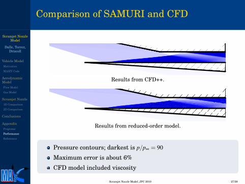
Comparison of SAMURI and CFD
Results from CFD++.
Results from reduced-order model.
Pressure contours; darkest is p/p∞ = 90
Maximum error is about 6%
CFD model included viscosity
CCCS
Scramjet Nozzle Model, JPC 2010 27/29

Scramjet NozzleModel
Dalle, Torrez,Driscoll
Vehicle ModelMotivation
MASIV Code
AerodynamicModelFlow Model
Gas Model
Scramjet Nozzle1D Comparison
2D Comparison
Conclusions
AppendixPrograms
Performance
References
Bibliography
Vogel, J. M., Kelkar, A. G., Inger, G., Whitmer, C., Sidlinger, A., andRodriquez, A., “Control-Relevant Modeling of Hypersonic Vehicles,” 2009American Control Confernce, 2009.
Oppenheimer, M. W., Skujins, T., Bolender, M. A., and Doman, D. B., “AFlexible Hypersonic Vehicle Model Developed with Piston Theory,” 2007Atmospheric Flight Mechanics Conference and Exhibit, AIAA Paper No.2007-6396, August 2007.
Bolender, M. A. and Doman, D. B., “Nonlinear Longitudinal DynamicalModel of an Air-Breathing Hypersonic Vehicle,” Journal of Spacecraftand Rockets, Vol. 44, No. 2, 2007, pp. 374-387.
Chavez, F. R. and Schmidt, D. K., “Analytical Aeropropulsive/AeroelasticHypersonic-Vehicle Model with Dynamic Analysis,” Journal of Guidance,Control, and Dynamics, Vol. 17, No. 6, 1994, pp. 1308-1319.
O’Brien, T. F., Starkey, R. P., and Lewis, M. J., “Quasi-One-DimensionalHigh-Speed Engine Model with Finite-Rate Chemistry,” Journal ofPropulsion and Power, Vol. 17, No. 6, 2001, pp. 1366-1374.
Jachimowski, C. J., “An analytic study of the Hyrdogen-Air reactionmechanism with application to SCRAMJET combustion,” NASATehcnical Paper 2791, 1988
CCCS
Scramjet Nozzle Model, JPC 2010 28/29

Scramjet NozzleModel
Dalle, Torrez,Driscoll
Vehicle ModelMotivation
MASIV Code
AerodynamicModelFlow Model
Gas Model
Scramjet Nozzle1D Comparison
2D Comparison
Conclusions
AppendixPrograms
Performance
References
Papers by our group
Torrez, S. M., Dalle, D. J., and Driscoll, J. F., “Dual Mode Scramjet Design toAchieve Improved Operational Stability,” 46th AIAA/ASME/SAE/ASEE JointPropulsion Conference and Exhibit, 2010.Dalle, D. J., Fotia, M. L., and Driscoll, J. F., “Reduced-Order Modeling ofTwo-Dimensional Supersonic Flows with Applications to Scramjet Inlets,” Journalof Propulsion and Power, Vol. 26, No. 3, 2010, pp. 545-555.Frendreis, S. G. V., Skujins, T., and Cesnik, C. E. S., “Six-Degree-of-FreedomSimulation of Hypersonic Vehicles,” AIAA Atmospheric Flight Mechanics Conference& Exhibit, 2009, AIAA Paper 2009-5601.Torrez, S. M., Driscoll, J. F., Dalle, D. J., and Fotia, M. L., “Preliminary DesignMethodology for Hypersonic Engine Flowpaths,” 16th AIAA/DLR/DGLR/International Space Planes and Hypersonic Systems and Technologies Conference,2009, AIAA Paper 2009-7289.Dalle, D. J., Frendreis, S. G. V., Driscoll, J. F., and Cesnik, C. E. S., “HypersonicVehicle Flight Dynamics with Coupled Aerodynamics and Reduced-order PropulsiveModels,” AIAA Atmospheric Flight Mechanics Conference and Exhibit, 2010.Frendreis, S. G. V., and Cesnik, C. E. S., “3D Simulation of a Flexible HypersonicVehicle,” AIAA Atmospheric Flight Mechanics Conference & Exhibit, 2010.
CCCS
Scramjet Nozzle Model, JPC 2010 29/29