
Red Hat JBoss BPM Suite 6 · Red Hat JBoss BPM Suite 6.1 User Guide The User Guide for Red Hat...
177
Red Hat JBoss BPM Suite 6.1 User Guide The User Guide for Red Hat JBoss BPM Suite Last Updated: 2017-11-13
Transcript of Red Hat JBoss BPM Suite 6 · Red Hat JBoss BPM Suite 6.1 User Guide The User Guide for Red Hat...
Red Hat JBoss BPM Suite 6.1
User Guide
The User Guide for Red Hat JBoss BPM Suite
Last Updated: 2017-11-13

Red Hat JBoss BPM Suite 6.1 User Guide
The User Guide for Red Hat JBoss BPM Suite
Doug Hoffman
Eva Kopalova
B LongRed Hat Engineering Content [email protected]
Gemma SheldonRed Hat Engineering Content [email protected]
Joshua [email protected]

Legal Notice
Copyright © 2015 Red Hat, Inc.
This document is licensed by Red Hat under the Creative Commons Attribution-ShareAlike 3.0Unported License. If you distribute this document, or a modified version of it, you must provideattribution to Red Hat, Inc. and provide a link to the original. If the document is modified, all Red Hattrademarks must be removed.
Red Hat, as the licensor of this document, waives the right to enforce, and agrees not to assert,Section 4d of CC-BY-SA to the fullest extent permitted by applicable law.
Red Hat, Red Hat Enterprise Linux, the Shadowman logo, JBoss, OpenShift, Fedora, the Infinitylogo, and RHCE are trademarks of Red Hat, Inc., registered in the United States and othercountries.
Linux ® is the registered trademark of Linus Torvalds in the United States and other countries.
Java ® is a registered trademark of Oracle and/or its affiliates.
XFS ® is a trademark of Silicon Graphics International Corp. or its subsidiaries in the United Statesand/or other countries.
MySQL ® is a registered trademark of MySQL AB in the United States, the European Union andother countries.
Node.js ® is an official trademark of Joyent. Red Hat Software Collections is not formally related toor endorsed by the official Joyent Node.js open source or commercial project.
The OpenStack ® Word Mark and OpenStack logo are either registered trademarks/service marksor trademarks/service marks of the OpenStack Foundation, in the United States and other countriesand are used with the OpenStack Foundation's permission. We are not affiliated with, endorsed orsponsored by the OpenStack Foundation, or the OpenStack community.
All other trademarks are the property of their respective owners.
Abstract
A guide to defining and managing business processes withRed Hat JBoss BPM Suite.
. . . . . . . . . . . . . . . . . . . . . . . . . . . . . . . . . . . . . . . . . . . . . . . . . . . . . . . . . . . . . . . . . . . . . . . . . . . . . . . . . . . . . . . . . . . . . . . . . . . . . . . . . . . . . . . . . . . . . . . . . . . . . . . . . . . . . . . . . . . . . . . . . . . . . . . . . . . . . . . . . . . . . . . . . . . . . . . . . . . . . . . . . . . . . . . . . . . . . . . . . . . . . . . . . . . . . . . . . . . . . . . . . . . . . . . . . . . . . . . . . . . . . . . . . . . . . . . . . . . . . . . . . . . . . . . . . . . . . . . .
. . . . . . . . . . . . . . . . . . . . . . . . . . . . . . . . . . . . . . . . . . . . . . . . . . . . . . . . . . . . . . . . . . . . . . . . . . . . . . . . . . . . . . . . . . . . . . . . . . . . . . . . . . . . . . . . . . . . . . . . . . . . . . . . . . . . . . . . . . . . . . . . . . . . . . . . . . . . . . . . . . . . . . . . . . . . . . . . . . . . . . . . . . . . . . . . . . . . . . . . . . . . . . . . . . . . . . . . . . . . . . . . . . . . . . . . . . . . . . . . . . . . . . . . . . . . . . . . . . . . . . . . . . . . . . . . . . . . . . . .
. . . . . . . . . . . . . . . . . . . . . . . . . . . . . . . . . . . . . . . . . . . . . . . . . . . . . . . . . . . . . . . . . . . . . . . . . . . . . . . . . . . . . . . . . . . . . . . . . . . . . . . . . . . . . . . . . . . . . . . . . . . . . . . . . . . . . . . . . . . . . . . . . . . . . . . . . . . . . . . . . . . . . . . . . . . . . . . . . . . . . . . . . . . . . . . . . . . . . . . . . . . . . . . . . . . . . . . . . . . . . . . . . . . . . . . . . . . . . . . . . . . . . . . . . . . . . . . . . . . . . . . . . . . . . . . . . . . . . . . .
. . . . . . . . . . . . . . . . . . . . . . . . . . . . . . . . . . . . . . . . . . . . . . . . . . . . . . . . . . . . . . . . . . . . . . . . . . . . . . . . . . . . . . . . . . . . . . . . . . . . . . . . . . . . . . . . . . . . . . . . . . . . . . . . . . . . . . . . . . . . . . . . . . . . . . . . . . . . . . . . . . . . . . . . . . . . . . . . . . . . . . . . . . . . . . . . . . . . . . . . . . . . . . . . . . . . . . . . . . . . . . . . . . . . . . . . . . . . . . . . . . . . . . . . . . . . . . . . . . . . . . . . . . . . . . . . . . . . . . . .
. . . . . . . . . . . . . . . . . . . . . . . . . . . . . . . . . . . . . . . . . . . . . . . . . . . . . . . . . . . . . . . . . . . . . . . . . . . . . . . . . . . . . . . . . . . . . . . . . . . . . . . . . . . . . . . . . . . . . . . . . . . . . . . . . . . . . . . . . . . . . . . . . . . . . . . . . . . . . . . . . . . . . . . . . . . . . . . . . . . . . . . . . . . . . . . . . . . . . . . . . . . . . . . . . . . . . . . . . . . . . . . . . . . . . . . . . . . . . . . . . . . . . . . . . . . . . . . . . . . . . . . . . . . . . . . . . . . . . . . .
. . . . . . . . . . . . . . . . . . . . . . . . . . . . . . . . . . . . . . . . . . . . . . . . . . . . . . . . . . . . . . . . . . . . . . . . . . . . . . . . . . . . . . . . . . . . . . . . . . . . . . . . . . . . . . . . . . . . . . . . . . . . . . . . . . . . . . . . . . . . . . . . . . . . . . . . . . . . . . . . . . . . . . . . . . . . . . . . . . . . . . . . . . . . . . . . . . . . . . . . . . . . . . . . . . . . . . . . . . . . . . . . . . . . . . . . . . . . . . . . . . . . . . . . . . . . . . . . . . . . . . . . . . . . . . . . . . . . . . . .
. . . . . . . . . . . . . . . . . . . . . . . . . . . . . . . . . . . . . . . . . . . . . . . . . . . . . . . . . . . . . . . . . . . . . . . . . . . . . . . . . . . . . . . . . . . . . . . . . . . . . . . . . . . . . . . . . . . . . . . . . . . . . . . . . . . . . . . . . . . . . . . . . . . . . . . . . . . . . . . . . . . . . . . . . . . . . . . . . . . . . . . . . . . . . . . . . . . . . . . . . . . . . . . . . . . . . . . . . . . . . . . . . . . . . . . . . . . . . . . . . . . . . . . . . . . . . . . . . . . . . . . . . . . . . . . . . . . . . . . .
. . . . . . . . . . . . . . . . . . . . . . . . . . . . . . . . . . . . . . . . . . . . . . . . . . . . . . . . . . . . . . . . . . . . . . . . . . . . . . . . . . . . . . . . . . . . . . . . . . . . . . . . . . . . . . . . . . . . . . . . . . . . . . . . . . . . . . . . . . . . . . . . . . . . . . . . . . . . . . . . . . . . . . . . . . . . . . . . . . . . . . . . . . . . . . . . . . . . . . . . . . . . . . . . . . . . . . . . . . . . . . . . . . . . . . . . . . . . . . . . . . . . . . . . . . . . . . . . . . . . . . . . . . . . . . . . . . . . . . . .
. . . . . . . . . . . . . . . . . . . . . . . . . . . . . . . . . . . . . . . . . . . . . . . . . . . . . . . . . . . . . . . . . . . . . . . . . . . . . . . . . . . . . . . . . . . . . . . . . . . . . . . . . . . . . . . . . . . . . . . . . . . . . . . . . . . . . . . . . . . . . . . . . . . . . . . . . . . . . . . . . . . . . . . . . . . . . . . . . . . . . . . . . . . . . . . . . . . . . . . . . . . . . . . . . . . . . . . . . . . . . . . . . . . . . . . . . . . . . . . . . . . . . . . . . . . . . . . . . . . . . . . . . . . . . . . . . . . . . . . .
. . . . . . . . . . . . . . . . . . . . . . . . . . . . . . . . . . . . . . . . . . . . . . . . . . . . . . . . . . . . . . . . . . . . . . . . . . . . . . . . . . . . . . . . . . . . . . . . . . . . . . . . . . . . . . . . . . . . . . . . . . . . . . . . . . . . . . . . . . . . . . . . . . . . . . . . . . . . . . . . . . . . . . . . . . . . . . . . . . . . . . . . . . . . . . . . . . . . . . . . . . . . . . . . . . . . . . . . . . . . . . . . . . . . . . . . . . . . . . . . . . . . . . . . . . . . . . . . . . . . . . . . . . . . . . . . . . . . . . . .
Table of Contents
CHAPTER 1. INTRODUCTION1.1. USE CASE: PROCESS -BASED SOLUTIONS IN THE LOAN INDUSTRY1.2. COMPONENTS1.3. RED HAT JBOSS BPM SUITE AND BRMS1.4. BUSINESS CENTRAL
CHAPTER 2. BASIC CONCEPTS
PART I. MODELING
CHAPTER 3. PROJECT3.1. CREATING A PROJECT3.2. ADDING DEPENDENCIES3.3. DEFINING KIE BASE3.4. DEFINING SESSIONS3.5. CREATING A RESOURCE3.6. ASSET METADATA AND VERSIONING3.7. PROCESS DEFINITION3.8. SYSTEM PROPERTIES
CHAPTER 4. PROCESS DESIGNER4.1. CONFIGURING AUTOMATIC SAVING4.2. DEFINING PROCESS PROPERTIES4.3. DESIGNING A PROCESS4.4. EXPORTING A PROCESS4.5. PROCESS ELEMENTS4.6. FORMS4.7. FORM MODELER4.8. VARIABLES4.9. ACTION SCRIPTS4.10. INTERCEPTOR ACTIONS4.11. ASSIGNMENT4.12. CONSTRAINTS4.13. DATA MODELS4.14. DOMAIN-SPECIFIC TASKS4.15. EXCEPTION MANAGEMENT
CHAPTER 5. ADVANCED PROCESS MODELING5.1. PROCESS MODELING OPTIONS5.2. WORKFLOW PATTERNS
CHAPTER 6. SOCIAL EVENTSFOLLOW USERACTIVITY TIMELINE
PART II. SIMULATION AND TESTING
CHAPTER 7. PROCESS SIMULATION7.1. PATH FINDER7.2. SIMULATING A PROCESS
CHAPTER 8. TESTING8.1. UNIT TESTING8.2. SESSION CREATION
55666
11
13
141415161819202124
27282829333435375356575758606177
797996
989898
99
100100101
106106107
Table of Contents
1
. . . . . . . . . . . . . . . . . . . . . . . . . . . . . . . . . . . . . . . . . . . . . . . . . . . . . . . . . . . . . . . . . . . . . . . . . . . . . . . . . . . . . . . . . . . . . . . . . . . . . . . . . . . . . . . . . . . . . . . . . . . . . . . . . . . . . . . . . . . . . . . . . . . . . . . . . . . . . . . . . . . . . . . . . . . . . . . . . . . . . . . . . . . . . . . . . . . . . . . . . . . . . . . . . . . . . . . . . . . . . . . . . . . . . . . . . . . . . . . . . . . . . . . . . . . . . . . . . . . . . . . . . . . . . . . . . . . . . . . .
. . . . . . . . . . . . . . . . . . . . . . . . . . . . . . . . . . . . . . . . . . . . . . . . . . . . . . . . . . . . . . . . . . . . . . . . . . . . . . . . . . . . . . . . . . . . . . . . . . . . . . . . . . . . . . . . . . . . . . . . . . . . . . . . . . . . . . . . . . . . . . . . . . . . . . . . . . . . . . . . . . . . . . . . . . . . . . . . . . . . . . . . . . . . . . . . . . . . . . . . . . . . . . . . . . . . . . . . . . . . . . . . . . . . . . . . . . . . . . . . . . . . . . . . . . . . . . . . . . . . . . . . . . . . . . . . . . . . . . . .
. . . . . . . . . . . . . . . . . . . . . . . . . . . . . . . . . . . . . . . . . . . . . . . . . . . . . . . . . . . . . . . . . . . . . . . . . . . . . . . . . . . . . . . . . . . . . . . . . . . . . . . . . . . . . . . . . . . . . . . . . . . . . . . . . . . . . . . . . . . . . . . . . . . . . . . . . . . . . . . . . . . . . . . . . . . . . . . . . . . . . . . . . . . . . . . . . . . . . . . . . . . . . . . . . . . . . . . . . . . . . . . . . . . . . . . . . . . . . . . . . . . . . . . . . . . . . . . . . . . . . . . . . . . . . . . . . . . . . . . .
. . . . . . . . . . . . . . . . . . . . . . . . . . . . . . . . . . . . . . . . . . . . . . . . . . . . . . . . . . . . . . . . . . . . . . . . . . . . . . . . . . . . . . . . . . . . . . . . . . . . . . . . . . . . . . . . . . . . . . . . . . . . . . . . . . . . . . . . . . . . . . . . . . . . . . . . . . . . . . . . . . . . . . . . . . . . . . . . . . . . . . . . . . . . . . . . . . . . . . . . . . . . . . . . . . . . . . . . . . . . . . . . . . . . . . . . . . . . . . . . . . . . . . . . . . . . . . . . . . . . . . . . . . . . . . . . . . . . . . . .
. . . . . . . . . . . . . . . . . . . . . . . . . . . . . . . . . . . . . . . . . . . . . . . . . . . . . . . . . . . . . . . . . . . . . . . . . . . . . . . . . . . . . . . . . . . . . . . . . . . . . . . . . . . . . . . . . . . . . . . . . . . . . . . . . . . . . . . . . . . . . . . . . . . . . . . . . . . . . . . . . . . . . . . . . . . . . . . . . . . . . . . . . . . . . . . . . . . . . . . . . . . . . . . . . . . . . . . . . . . . . . . . . . . . . . . . . . . . . . . . . . . . . . . . . . . . . . . . . . . . . . . . . . . . . . . . . . . . . . . .
. . . . . . . . . . . . . . . . . . . . . . . . . . . . . . . . . . . . . . . . . . . . . . . . . . . . . . . . . . . . . . . . . . . . . . . . . . . . . . . . . . . . . . . . . . . . . . . . . . . . . . . . . . . . . . . . . . . . . . . . . . . . . . . . . . . . . . . . . . . . . . . . . . . . . . . . . . . . . . . . . . . . . . . . . . . . . . . . . . . . . . . . . . . . . . . . . . . . . . . . . . . . . . . . . . . . . . . . . . . . . . . . . . . . . . . . . . . . . . . . . . . . . . . . . . . . . . . . . . . . . . . . . . . . . . . . . . . . . . . .
. . . . . . . . . . . . . . . . . . . . . . . . . . . . . . . . . . . . . . . . . . . . . . . . . . . . . . . . . . . . . . . . . . . . . . . . . . . . . . . . . . . . . . . . . . . . . . . . . . . . . . . . . . . . . . . . . . . . . . . . . . . . . . . . . . . . . . . . . . . . . . . . . . . . . . . . . . . . . . . . . . . . . . . . . . . . . . . . . . . . . . . . . . . . . . . . . . . . . . . . . . . . . . . . . . . . . . . . . . . . . . . . . . . . . . . . . . . . . . . . . . . . . . . . . . . . . . . . . . . . . . . . . . . . . . . . . . . . . . . .
. . . . . . . . . . . . . . . . . . . . . . . . . . . . . . . . . . . . . . . . . . . . . . . . . . . . . . . . . . . . . . . . . . . . . . . . . . . . . . . . . . . . . . . . . . . . . . . . . . . . . . . . . . . . . . . . . . . . . . . . . . . . . . . . . . . . . . . . . . . . . . . . . . . . . . . . . . . . . . . . . . . . . . . . . . . . . . . . . . . . . . . . . . . . . . . . . . . . . . . . . . . . . . . . . . . . . . . . . . . . . . . . . . . . . . . . . . . . . . . . . . . . . . . . . . . . . . . . . . . . . . . . . . . . . . . . . . . . . . . .
. . . . . . . . . . . . . . . . . . . . . . . . . . . . . . . . . . . . . . . . . . . . . . . . . . . . . . . . . . . . . . . . . . . . . . . . . . . . . . . . . . . . . . . . . . . . . . . . . . . . . . . . . . . . . . . . . . . . . . . . . . . . . . . . . . . . . . . . . . . . . . . . . . . . . . . . . . . . . . . . . . . . . . . . . . . . . . . . . . . . . . . . . . . . . . . . . . . . . . . . . . . . . . . . . . . . . . . . . . . . . . . . . . . . . . . . . . . . . . . . . . . . . . . . . . . . . . . . . . . . . . . . . . . . . . . . . . . . . . . .
. . . . . . . . . . . . . . . . . . . . . . . . . . . . . . . . . . . . . . . . . . . . . . . . . . . . . . . . . . . . . . . . . . . . . . . . . . . . . . . . . . . . . . . . . . . . . . . . . . . . . . . . . . . . . . . . . . . . . . . . . . . . . . . . . . . . . . . . . . . . . . . . . . . . . . . . . . . . . . . . . . . . . . . . . . . . . . . . . . . . . . . . . . . . . . . . . . . . . . . . . . . . . . . . . . . . . . . . . . . . . . . . . . . . . . . . . . . . . . . . . . . . . . . . . . . . . . . . . . . . . . . . . . . . . . . . . . . . . . . .
. . . . . . . . . . . . . . . . . . . . . . . . . . . . . . . . . . . . . . . . . . . . . . . . . . . . . . . . . . . . . . . . . . . . . . . . . . . . . . . . . . . . . . . . . . . . . . . . . . . . . . . . . . . . . . . . . . . . . . . . . . . . . . . . . . . . . . . . . . . . . . . . . . . . . . . . . . . . . . . . . . . . . . . . . . . . . . . . . . . . . . . . . . . . . . . . . . . . . . . . . . . . . . . . . . . . . . . . . . . . . . . . . . . . . . . . . . . . . . . . . . . . . . . . . . . . . . . . . . . . . . . . . . . . . . . . . . . . . . . .
. . . . . . . . . . . . . . . . . . . . . . . . . . . . . . . . . . . . . . . . . . . . . . . . . . . . . . . . . . . . . . . . . . . . . . . . . . . . . . . . . . . . . . . . . . . . . . . . . . . . . . . . . . . . . . . . . . . . . . . . . . . . . . . . . . . . . . . . . . . . . . . . . . . . . . . . . . . . . . . . . . . . . . . . . . . . . . . . . . . . . . . . . . . . . . . . . . . . . . . . . . . . . . . . . . . . . . . . . . . . . . . . . . . . . . . . . . . . . . . . . . . . . . . . . . . . . . . . . . . . . . . . . . . . . . . . . . . . . . . .
. . . . . . . . . . . . . . . . . . . . . . . . . . . . . . . . . . . . . . . . . . . . . . . . . . . . . . . . . . . . . . . . . . . . . . . . . . . . . . . . . . . . . . . . . . . . . . . . . . . . . . . . . . . . . . . . . . . . . . . . . . . . . . . . . . . . . . . . . . . . . . . . . . . . . . . . . . . . . . . . . . . . . . . . . . . . . . . . . . . . . . . . . . . . . . . . . . . . . . . . . . . . . . . . . . . . . . . . . . . . . . . . . . . . . . . . . . . . . . . . . . . . . . . . . . . . . . . . . . . . . . . . . . . . . . . . . . . . . . . .
PART III. PLUG-IN
CHAPTER 9. PLUG-IN9.1. CREATING BPM PROJECT9.2. CREATING PROCESS9.3. USING THE DEBUG PERSPECTIVE9.4. CHECKING SESSION LOGS
PART IV. DEPLOYMENT AND RUNTIME MANAGEMENT
CHAPTER 10. DEPLOYING PROJECTS10.1. PROCESS INSTANCES10.2. USER TASKS
CHAPTER 11. LOGGING
CHAPTER 12. EXAMPLES
PART V. BAM
CHAPTER 13. RED HAT JBOSS DASHBOARD BUILDERWHAT IS BUSINESS ACTIVITY MONITORING?13.1. ACCESSING DASHBOARD BUILDER13.2. BASIC CONCEPTS13.3. ENVIRONMENT13.4. DATA SOURCES
CHAPTER 14. MANAGEMENT CONSOLE
CHAPTER 15. GRAPHIC RESOURCESGRAPHIC RESOURCES DEFINITIONS15.1. WORKING WITH GRAPHIC RESOURCES
APPENDIX A. PROCESS ELEMENTSA.1. PROCESSA.2. EVENTS MECHANISMA.3. COLLABORATION MECHANISMSA.4. TRANSACTION MECHANISMSA.5. TIMINGA.6. PROCESS ELEMENTSA.7. START EVENTA.8. INTERMEDIATE EVENTSA.9. END EVENTSA.10. GATEWAYSA.11. ACTIVITIES, TASKS AND SUB-PROCESSESA.12. CONNECTING OBJECTSA.13. SWIMLANESA.14. ARTIFACTS
APPENDIX B. SERVICE TASKSB.1. LOG TASKB.2. EMAIL TASKB.3. REST TASKB.4. WS TASK
APPENDIX C. SIMULATION DATAC.1. PROCESS
111
112112112113114
116
117117118
120
121
122
123123123123124124
133
134134134
135135137138140141142143145150152154162163164
166166166166167
169169
User Guide
2

. . . . . . . . . . . . . . . . . . . . . . . . . . . . . . . . . . . . . . . . . . . . . . . . . . . . . . . . . . . . . . . . . . . . . . . . . . . . . . . . . . . . . . . . . . . . . . . . . . . . . . . . . . . . . . . . . . . . . . . . . . . . . . . . . . . . . . . . . . . . . . . . . . . . . . . . . . . . . . . . . . . . . . . . . . . . . . . . . . . . . . . . . . . . . . . . . . . . . . . . . . . . . . . . . . . . . . . . . . . . . . . . . . . . . . . . . . . . . . . . . . . . . . . . . . . . . . . . . . . . . . . . . . . . . . . . . . . . . . . .
C.2. START EVENTC.3. CATCHING INTERMEDIATE EVENTSC.4. SEQUENCE FLOWC.5. THROWING INTERMEDIATE EVENTSC.6. HUMAN TASKSC.7. SERVICE TASKSC.8. END EVENTSC.9. DISTRIBUTION TYPES
APPENDIX D. REVISION HISTORY
169169169169170170171171
173
Table of Contents
3

User Guide
4
CHAPTER 1. INTRODUCTIONRed Hat JBoss BPM Suite is an open source business process management suite that combinesBusiness Process Management and Business Rules Management and enables business and IT users tocreate, manage, validate, and deploy Business Processes and Rules.
To accommodate Business Rules component, JBoss BPM Suite includes integrated Red Hat JBossBRMS.
Red Hat JBoss BRMS and Red Hat JBoss BPM Suite use a centralized repository where all resourcesare stored. This ensures consistency, transparency, and the ability to audit across the business.Business users can modify business logic and business processes without requiring assistance from ITpersonnel.
Business Resource Planner is also included with this release.
1.1. USE CASE: PROCESS -BASED SOLUTIONS IN THE LOANINDUSTRY
This section describes a use case of deploying JBoss BPM Suite to automate business processes (suchas loan approval process) at a retail bank. This use case is a typical process-based specific deploymentthat might be the first step in a wider adoption of JBoss BPM Suite throughout an enterprise. It leveragesfeatures of both business rules and processes of JBoss BPM Suite.
A retail bank offers several types of loan products each with varying terms and eligibility requirements.Customers requiring a loan must file a loan application with the bank. The bank then processes theapplication in several steps, such as verifying eligibility, determining terms, checking for fraudulentactivity, and determining the most appropriate loan product. Once approved, the bank creates and fundsa loan account for the applicant, who can then access funds. The bank must be sure to comply with allrelevant banking regulations at each step of the process, and has to manage its loan portfolio tomaximize profitability. Policies are in place to aid in decision making at each step, and those policies areactively managed to optimize outcomes for the bank.
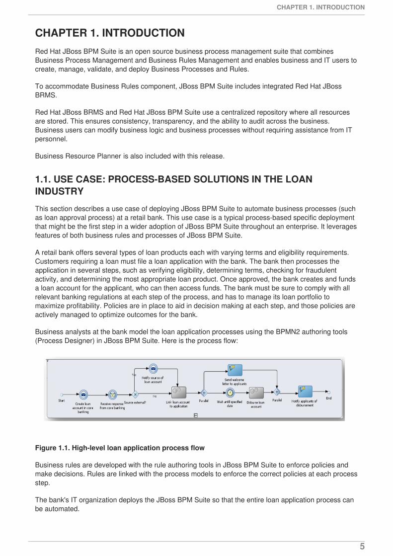
Business analysts at the bank model the loan application processes using the BPMN2 authoring tools(Process Designer) in JBoss BPM Suite. Here is the process flow:
Figure 1.1. High-level loan application process flow
Business rules are developed with the rule authoring tools in JBoss BPM Suite to enforce policies andmake decisions. Rules are linked with the process models to enforce the correct policies at each processstep.
The bank's IT organization deploys the JBoss BPM Suite so that the entire loan application process canbe automated.
CHAPTER 1. INTRODUCTION
5
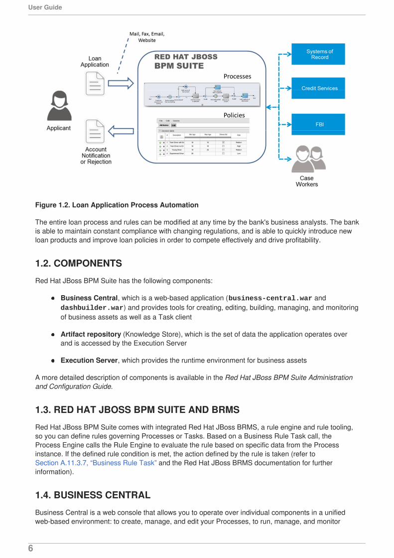
Figure 1.2. Loan Application Process Automation
The entire loan process and rules can be modified at any time by the bank's business analysts. The bankis able to maintain constant compliance with changing regulations, and is able to quickly introduce newloan products and improve loan policies in order to compete effectively and drive profitability.
1.2. COMPONENTS
Red Hat JBoss BPM Suite has the following components:
Business Central, which is a web-based application (business-central.war and dashbuilder.war) and provides tools for creating, editing, building, managing, and monitoringof business assets as well as a Task client
Artifact repository (Knowledge Store), which is the set of data the application operates overand is accessed by the Execution Server
Execution Server, which provides the runtime environment for business assets
A more detailed description of components is available in the Red Hat JBoss BPM Suite Administrationand Configuration Guide.
1.3. RED HAT JBOSS BPM SUITE AND BRMS
Red Hat JBoss BPM Suite comes with integrated Red Hat JBoss BRMS, a rule engine and rule tooling,so you can define rules governing Processes or Tasks. Based on a Business Rule Task call, theProcess Engine calls the Rule Engine to evaluate the rule based on specific data from the Processinstance. If the defined rule condition is met, the action defined by the rule is taken (refer toSection A.11.3.7, “Business Rule Task” and the Red Hat JBoss BRMS documentation for furtherinformation).
1.4. BUSINESS CENTRAL
Business Central is a web console that allows you to operate over individual components in a unifiedweb-based environment: to create, manage, and edit your Processes, to run, manage, and monitor
User Guide
6
Process instances, generate reports, and manage the Tasks produced, as well as create new Tasks andnotifications.
Process management capabilities allow you to start new process instances, acquire the list ofrunning process instances, inspect the state of a specific process instances, etc.
User Task management capabilities allow you to work with User Tasks; claim User Tasks,complete Tasks through Task forms, etc.
Business Central integrates multiple tools:
Process Designer and other editors for modeling Processes and their resources (form itemeditor, work item editor, data model editor, etc.), as well as process model simulation tools (referto Chapter 4, Process Designer)
Rules Modeler for designing Business Rules models and their resources (refer to Red HatJBoss BRMS documentation)
Task client for managing and creating User Tasks (refer to Section 10.2, “User tasks”)
Process Manager for managing process instances (refer to Section 10.1, “Process instances”)
Dashboard Builder, the BAM component, for monitoring and reporting (refer to Chapter 13, RedHat JBoss Dashboard Builder)
Business Asset Manager for accessing the Knowledge Repository resources, building anddeploying business assets (refer to Chapter 3, Project)
Artifact repository (Knowledge Store) is the set of data over which Business Central operates. Itprovides a centralized store for your business knowledge, which can consist of multiplerepositories with business assets and resources (for further information, refer to the Red HatJBoss BPM Suite Administration and Configuration Guide).
Business Central can be accessed from your web browser on https://HOSTNAME/business-central (forinstances running on localhost https://localhost:8080/business-central).
The tools are accessible from the Views and BPM menus on the main menu:
Process Definitions displays the Process Definition List with the Processdefinitions available in the connected repository.
Process Instances displays the Process Instance List with the Process instancescurrently running on the Process Engine.
Tasks displays a view of the Tasks list for the currently logged-in user. You can call a Task Listin the grid view or in the calendar view from the BPM menu.
1.4.1. Business Central Environment
CHAPTER 1. INTRODUCTION
7
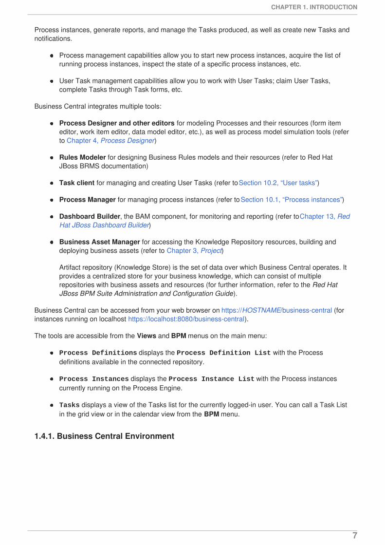
The main menu contains the links to the Home page and all available perspectives.
The perspective menu contains menus for the selected perspective (here it is empty; note that thecontent differs for individual perspectives) Section 1.4.2, “Perspectives”.
The perspective area contains the perspective tools (here the home page with links to individualperspectives and their views), such as views and editors.
Figure 1.3. Home page
1.4.2. Perspectives
Business Central provides the following groups of perspectives accessible from the main menu:
Authoring group:
Project Authoring perspective contains the Project Explorer view (by default onthe left) with the overview of available repository structure, and information on availableresources, such as, business process definitions, form definitions, etc.; the editor area onthe right, where the respective editor appears when a resource is opened; and the Messages view with validation messages.
Artifact Repository perspective contains a list of jars which can be added asdependencies. The available operations in this perspective are upload/download artifact andopen (view) the pom.xml file.
Administration perspective (available only for users with the ADMIN role) contains the File Explorer view (by default on the left) with available asset repositories; the editorarea on the right, where the respective editor appears when a resource is opened. Theperspective allows an administrator to connect Knowledge Store to a repository with assetsand to create a new repository (refer to Administration and Configuration Guide).
Deploy group:
Deployments perspective contains a list of the deployed resources and allows you to buildand deploy an undeploy new units.
User Guide
8
Process Management group:
Process Definitions perspective contains a list of the deployed Process definitions. Itallows you to instantiate and manage the deployed Processes.
Process Instances perspective contains a list of the instantiated Processes. It allowsyou to view their execution worklow and its history.
Tasks group:
Task List perspective contains a list of Tasks produced by Human Task of the Processinstances or produced manually. Only Tasks assigned to the logged-in user are visible. Itallows you to claim Tasks assigned to a group you are a member of.
Dashboards group (the BAM component):
Process & Task Dashboard perspective contains a prepared dashboard with statisticson runtime data of the Execution Server
Business Dashboards perspective contains the full BAM component, the Dashbuilder,including administration features available for users with the ADMIN role.
1.4.3. Embedding Business Central
Business Central provides a set of editors to author assets in different formats. A specialized editor isused according to the asset format.
Business Central provides the ability to embed it in your own (Web) Applications using standalone mode.This allows you to edit rules, processes, decision tables, et cetera, in your own applications withoutswitching to Business Central.
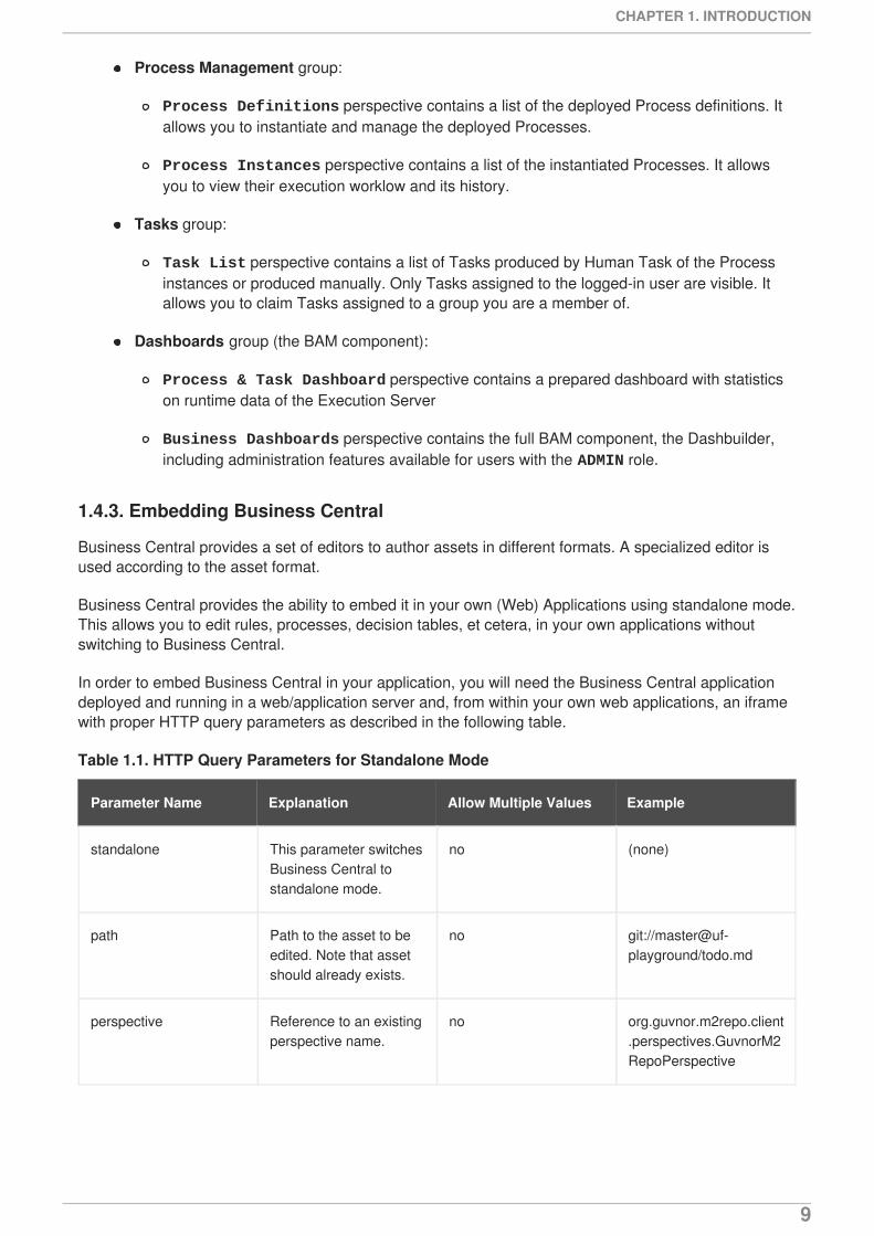
In order to embed Business Central in your application, you will need the Business Central applicationdeployed and running in a web/application server and, from within your own web applications, an iframewith proper HTTP query parameters as described in the following table.
Table 1.1. HTTP Query Parameters for Standalone Mode
Parameter Name Explanation Allow Multiple Values Example
standalone This parameter switchesBusiness Central tostandalone mode.
no (none)
path Path to the asset to beedited. Note that assetshould already exists.
no git://master@uf-playground/todo.md
perspective Reference to an existingperspective name.
no org.guvnor.m2repo.client.perspectives.GuvnorM2RepoPerspective
CHAPTER 1. INTRODUCTION
9
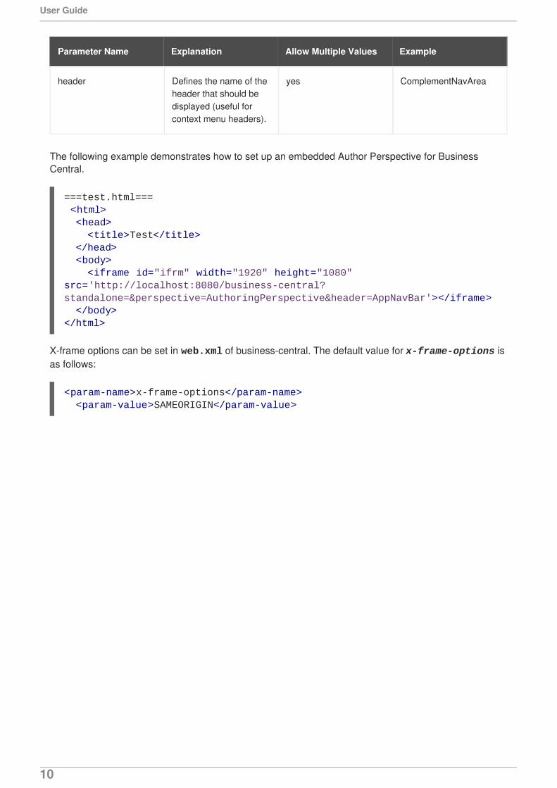
header Defines the name of theheader that should bedisplayed (useful forcontext menu headers).
yes ComplementNavArea
Parameter Name Explanation Allow Multiple Values Example
The following example demonstrates how to set up an embedded Author Perspective for BusinessCentral.
X-frame options can be set in web.xml of business-central. The default value for x-frame-options isas follows:
===test.html=== <html> <head> <title>Test</title> </head> <body> <iframe id="ifrm" width="1920" height="1080" src='http://localhost:8080/business-central?standalone=&perspective=AuthoringPerspective&header=AppNavBar'></iframe> </body></html>
<param-name>x-frame-options</param-name> <param-value>SAMEORIGIN</param-value>
User Guide
10
CHAPTER 2. BASIC CONCEPTSRed Hat JBoss BPM Suite provides tools for creating, editing, running, and runtime management ofBPMN process models. The models are defined using the BPMN2 language, either directly in its XMLform or using visual BPMN Elements that represent the Process workflow (refer to Chapter 4, ProcessDesigner). Alternatively, you can create Processes from your Java application using the JBoss BPMSuite API. Some of these capabilities can be used also via REST API (See Red Hat JBoss BPM SuiteDeveloper Guide).
Process models serve as templates for Process instances. To separate the static Process models fromtheir dynamic runtime versions (Process instances), they live in two different entities: Process modelslive in a Kie Base (or Knowledge Base) and their data cannot be changed by the Process Engine;Process instances live in a Kie Session(or Knowledge Session) which exists in the Process Engine andcontains the runtime data, which are changed during runtime by the Process Engine.
You can define a Kie Base and its Kie Session in the Project Editor of the GUI application or using theprovided API (refer to Section 3.3, “Defining Kie Base” and Section 3.4, “Defining Sessions”).
Note that a single Kie Base can be shared across multiple Kie Sessions. When instantiating a Kie Baseusing the respective API call it is usual to create one Kie Base at the start of your application as creatinga Kie Base can be rather heavy-weight as it involves parsing and compiling the process definitions. Fromthe Kie Base, you can then start multiple Kie Sessions. The underlying Kie Bases can be changed atruntime so you can add, remove, or migrate process definitions.
To have multiple independent processing units, it might be convenient to create multiple Kie Sessions onthe particular Kie Base (for example, if you want all process instances from one customer to beindependent from process instances for another customer; multiple Sessions might be useful forscalability reasons as well).
A Kie Session can be either stateful or stateless. Stateful sessions are long-living sessions with explicitcall to dispose them; if the dispose() call is not issued, the session remains alive and causes memoryleaks. Also note that the FireAllRules command is not automatically called at the end of a statefulsession.
CHAPTER 2. BASIC CONCEPTS
11
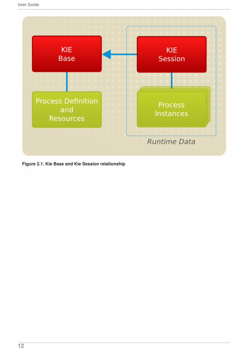
Figure 2.1. Kie Base and Kie Session relationship
User Guide
12

PART I. MODELING
PART I. MODELING
13
CHAPTER 3. PROJECTA project is a container for asset packages (business processes, rules, work definitions, decision tables,fact models, data models, and DSLs) that lives in the Knowledge Repository. It is this container thatdefines the properties of the KIE Base and KIE Session that are applied to its content. In the GUI, youcan edit these entities in the Project Editor.
As a project is a Maven project, it contains the Project Object Model file (pom.xml) with information onhow to build the output artifact. It also contains the Module Descriptor file, kmodule.xml, that containsthe KIE Base and KIE Session configuration for the assets in the project.
3.1. CREATING A PROJECT
To create a project, do the following:
1. Open the Project Authoring perspective: on the main menu, click Authoring → ProjectAuthoring.
2. In the Project Explorer, select the organizational unit and the repository where you want tocreate the project.
3. In the perspective menu, go to New Item → Project.
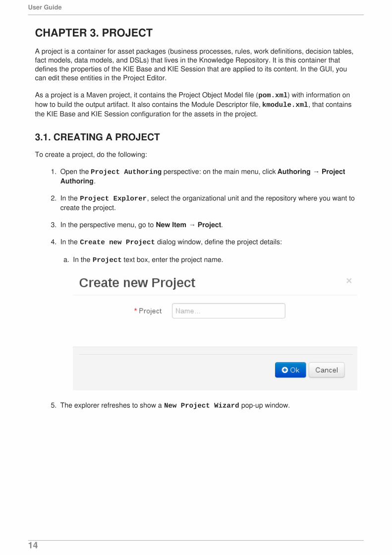
4. In the Create new Project dialog window, define the project details:
a. In the Project text box, enter the project name.
5. The explorer refreshes to show a New Project Wizard pop-up window.
User Guide
14
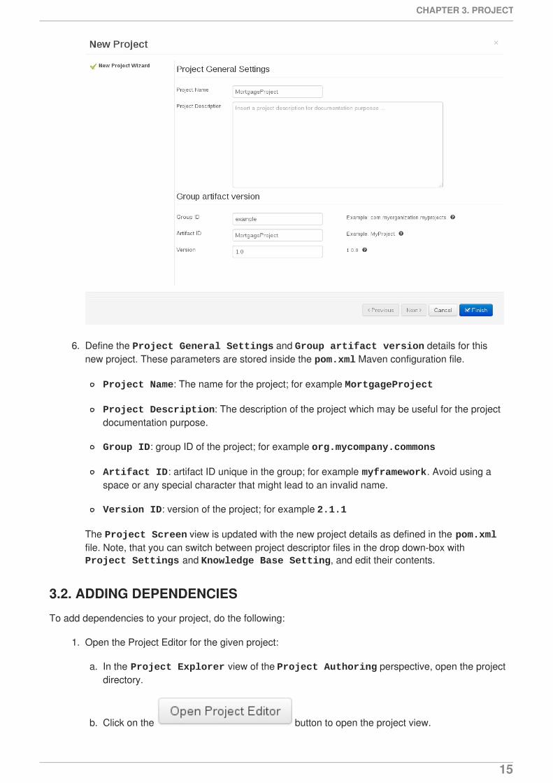
6. Define the Project General Settings and Group artifact version details for thisnew project. These parameters are stored inside the pom.xml Maven configuration file.
Project Name: The name for the project; for example MortgageProject
Project Description: The description of the project which may be useful for the projectdocumentation purpose.
Group ID: group ID of the project; for example org.mycompany.commons
Artifact ID: artifact ID unique in the group; for example myframework. Avoid using aspace or any special character that might lead to an invalid name.
Version ID: version of the project; for example 2.1.1
The Project Screen view is updated with the new project details as defined in the pom.xmlfile. Note, that you can switch between project descriptor files in the drop down-box with Project Settings and Knowledge Base Setting, and edit their contents.
3.2. ADDING DEPENDENCIES
To add dependencies to your project, do the following:
1. Open the Project Editor for the given project:
a. In the Project Explorer view of the Project Authoring perspective, open the projectdirectory.
b. Click on the button to open the project view.
CHAPTER 3. PROJECT
15
2. In the Project Screen view, select in the Project Settings drop-down box the Dependencies item.
3. On the updated Project Screen, click the Add button to add a maven dependency or click theAdd from repository button to add a dependency from the Knowledge Store (Artifactrepository):
When adding a maven dependency, a user has to define the Group ID, Artifact ID andthe Version ID in the new row which is created in the dependency table.
When adding a dependency from the Knowledge Store, select the dependency in thedisplayed dialog box: the dependency will be added to the dependency table.
4. To apply the various changes, the dependencies must be saved.
WARNING
If working with modified artifacts, do not re-upload modified non-snapshot artifactsas Maven will not know these artifacts have been updated, and it will not work if it isdeployed in this manner.
3.3. DEFINING KIE BASE
You can create a Kie Base either using the API or in the kmodule.xml project descriptor file of yourproject via the Project Editor.
Defining Kie Base in the Project EditorTo define a Kie Base in the web environment, which is stored in the kmodule.xml file, do the following:
1. To open Project Explorer, click Authoring > Project Authoring and select or navigate toyour project.
2. Open your project properties in Project Editor: in the perspective menu, click Tools → ProjectEditor.
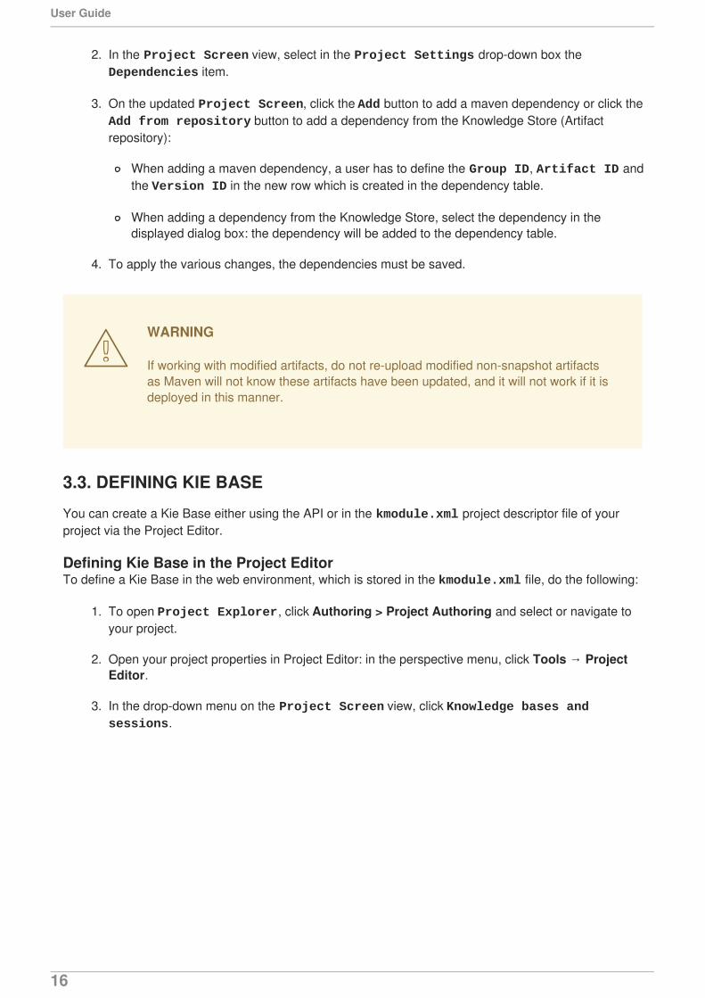
3. In the drop-down menu on the Project Screen view, click Knowledge bases and sessions.
User Guide
16
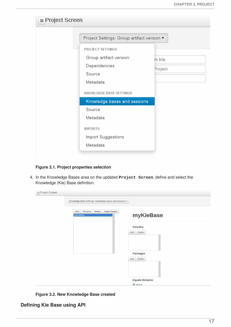
Figure 3.1. Project properties selection
4. In the Knowledge Bases area on the updated Project Screen, define and select theKnowledge (Kie) Base definition.
Figure 3.2. New Knowledge Base created
Defining Kie Base using API
CHAPTER 3. PROJECT
17
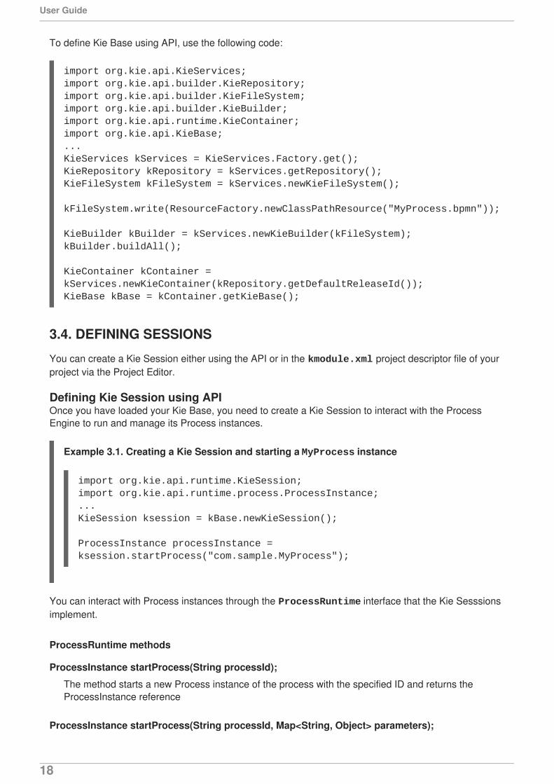
To define Kie Base using API, use the following code:
3.4. DEFINING SESSIONS
You can create a Kie Session either using the API or in the kmodule.xml project descriptor file of yourproject via the Project Editor.
Defining Kie Session using APIOnce you have loaded your Kie Base, you need to create a Kie Session to interact with the ProcessEngine to run and manage its Process instances.
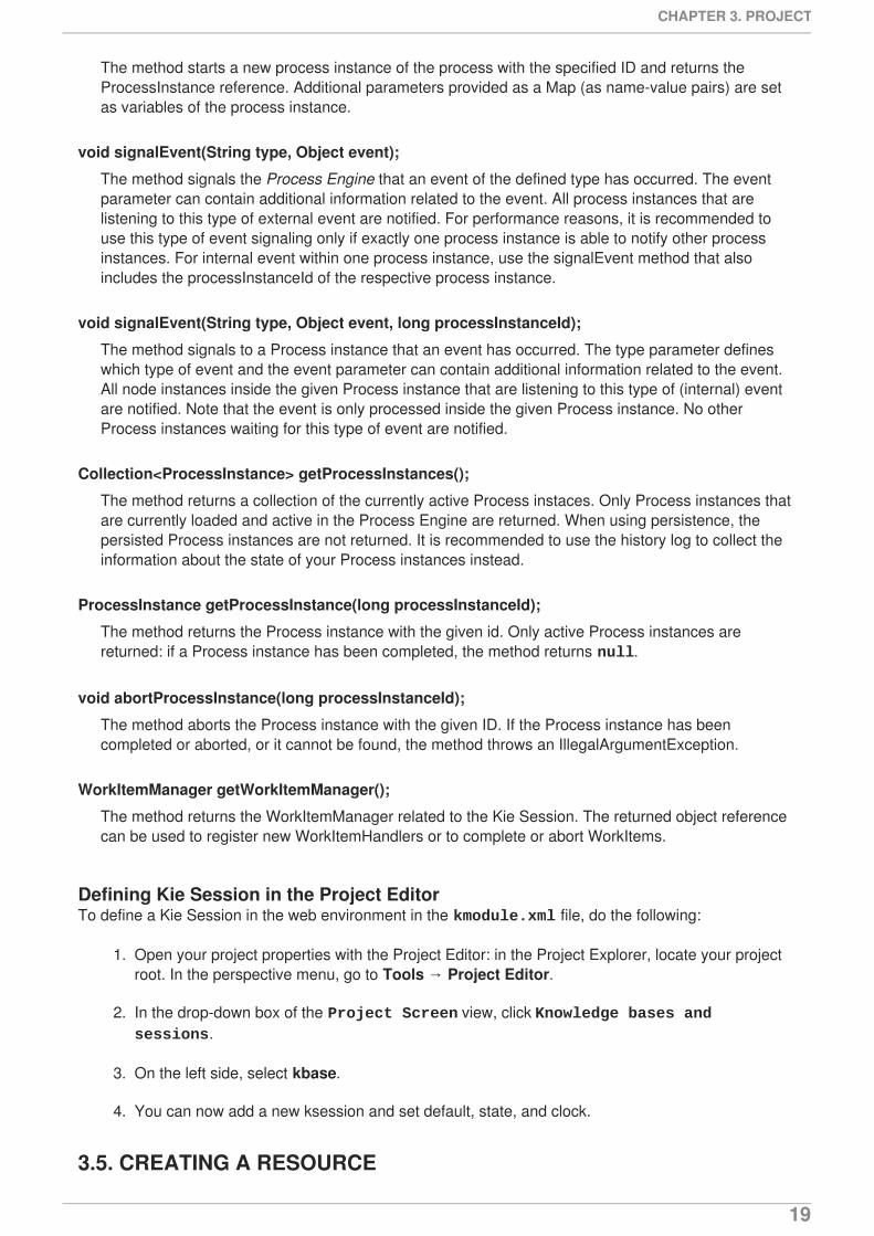
Example 3.1. Creating a Kie Session and starting a MyProcess instance
You can interact with Process instances through the ProcessRuntime interface that the Kie Sesssionsimplement.
ProcessRuntime methods
ProcessInstance startProcess(String processId);
The method starts a new Process instance of the process with the specified ID and returns theProcessInstance reference
ProcessInstance startProcess(String processId, Map<String, Object> parameters);
import org.kie.api.KieServices;import org.kie.api.builder.KieRepository;import org.kie.api.builder.KieFileSystem;import org.kie.api.builder.KieBuilder;import org.kie.api.runtime.KieContainer;import org.kie.api.KieBase;...KieServices kServices = KieServices.Factory.get();KieRepository kRepository = kServices.getRepository();KieFileSystem kFileSystem = kServices.newKieFileSystem();
kFileSystem.write(ResourceFactory.newClassPathResource("MyProcess.bpmn"));
KieBuilder kBuilder = kServices.newKieBuilder(kFileSystem);kBuilder.buildAll();
KieContainer kContainer = kServices.newKieContainer(kRepository.getDefaultReleaseId());KieBase kBase = kContainer.getKieBase();
import org.kie.api.runtime.KieSession;import org.kie.api.runtime.process.ProcessInstance;...KieSession ksession = kBase.newKieSession();
ProcessInstance processInstance = ksession.startProcess("com.sample.MyProcess");
User Guide
18
The method starts a new process instance of the process with the specified ID and returns theProcessInstance reference. Additional parameters provided as a Map (as name-value pairs) are setas variables of the process instance.
void signalEvent(String type, Object event);
The method signals the Process Engine that an event of the defined type has occurred. The eventparameter can contain additional information related to the event. All process instances that arelistening to this type of external event are notified. For performance reasons, it is recommended touse this type of event signaling only if exactly one process instance is able to notify other processinstances. For internal event within one process instance, use the signalEvent method that alsoincludes the processInstanceId of the respective process instance.
void signalEvent(String type, Object event, long processInstanceId);
The method signals to a Process instance that an event has occurred. The type parameter defineswhich type of event and the event parameter can contain additional information related to the event.All node instances inside the given Process instance that are listening to this type of (internal) eventare notified. Note that the event is only processed inside the given Process instance. No otherProcess instances waiting for this type of event are notified.
Collection<ProcessInstance> getProcessInstances();
The method returns a collection of the currently active Process instaces. Only Process instances thatare currently loaded and active in the Process Engine are returned. When using persistence, thepersisted Process instances are not returned. It is recommended to use the history log to collect theinformation about the state of your Process instances instead.
ProcessInstance getProcessInstance(long processInstanceId);
The method returns the Process instance with the given id. Only active Process instances arereturned: if a Process instance has been completed, the method returns null.
void abortProcessInstance(long processInstanceId);
The method aborts the Process instance with the given ID. If the Process instance has beencompleted or aborted, or it cannot be found, the method throws an IllegalArgumentException.
WorkItemManager getWorkItemManager();
The method returns the WorkItemManager related to the Kie Session. The returned object referencecan be used to register new WorkItemHandlers or to complete or abort WorkItems.
Defining Kie Session in the Project EditorTo define a Kie Session in the web environment in the kmodule.xml file, do the following:
1. Open your project properties with the Project Editor: in the Project Explorer, locate your projectroot. In the perspective menu, go to Tools → Project Editor.
2. In the drop-down box of the Project Screen view, click Knowledge bases and sessions.
3. On the left side, select kbase.
4. You can now add a new ksession and set default, state, and clock.
3.5. CREATING A RESOURCE
CHAPTER 3. PROJECT
19
A Project may contain an arbitrary number of packages, which contain files with resources, such asProcess definition, Work Item definition, Form definition, Business Rule definition, etc.
To create a resource, select the Project and the package in the Project Explorer and click NewItem on the perspective menu and select the resource you want to create.
NOTE
It is recommended to create your resources, such as Process definitions, Work Itemdefinitions, Data Models, etc., inside a package of a Project to allow importing ofresources and referencing their content.
To create a package, do the following:
In the Repository view of the Project Explorer, navigate to the REPOSITORY/PROJECT/src/main/resources/ directory.
Go to New Item → Package.
In the New resource dialog, define the package name and check the locationof the package in the repository.
3.6. ASSET METADATA AND VERSIONING
Most assets within Business Central have some metadata and versioning information associated withthem. In this section, we will go through the metadata screens and version management for one suchasset (a DRL asset). Similar steps can be used to view and edit metadata and versions for other assets.
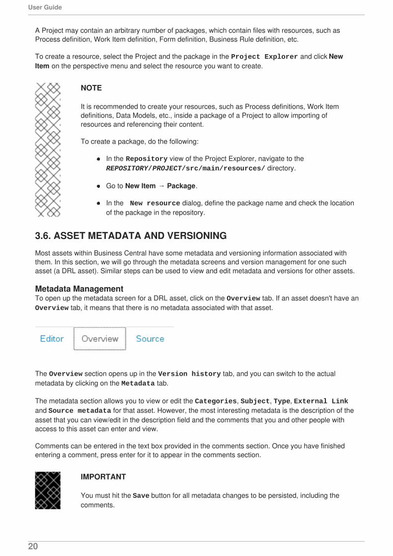
Metadata ManagementTo open up the metadata screen for a DRL asset, click on the Overview tab. If an asset doesn't have anOverview tab, it means that there is no metadata associated with that asset.
The Overview section opens up in the Version history tab, and you can switch to the actualmetadata by clicking on the Metadata tab.
The metadata section allows you to view or edit the Categories, Subject, Type, External Linkand Source metadata for that asset. However, the most interesting metadata is the description of theasset that you can view/edit in the description field and the comments that you and other people withaccess to this asset can enter and view.
Comments can be entered in the text box provided in the comments section. Once you have finishedentering a comment, press enter for it to appear in the comments section.
IMPORTANT
You must hit the Save button for all metadata changes to be persisted, including thecomments.
User Guide
20
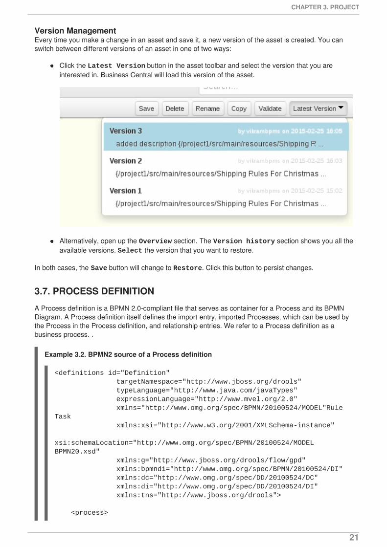
Version ManagementEvery time you make a change in an asset and save it, a new version of the asset is created. You canswitch between different versions of an asset in one of two ways:
Click the Latest Version button in the asset toolbar and select the version that you areinterested in. Business Central will load this version of the asset.
Alternatively, open up the Overview section. The Version history section shows you all theavailable versions. Select the version that you want to restore.
In both cases, the Save button will change to Restore. Click this button to persist changes.
3.7. PROCESS DEFINITION
A Process definition is a BPMN 2.0-compliant file that serves as container for a Process and its BPMNDiagram. A Process definition itself defines the import entry, imported Processes, which can be used bythe Process in the Process definition, and relationship entries. We refer to a Process definition as abusiness process. .
Example 3.2. BPMN2 source of a Process definition
<definitions id="Definition" targetNamespace="http://www.jboss.org/drools" typeLanguage="http://www.java.com/javaTypes" expressionLanguage="http://www.mvel.org/2.0" xmlns="http://www.omg.org/spec/BPMN/20100524/MODEL"Rule Task xmlns:xsi="http://www.w3.org/2001/XMLSchema-instance" xsi:schemaLocation="http://www.omg.org/spec/BPMN/20100524/MODEL BPMN20.xsd" xmlns:g="http://www.jboss.org/drools/flow/gpd" xmlns:bpmndi="http://www.omg.org/spec/BPMN/20100524/DI" xmlns:dc="http://www.omg.org/spec/DD/20100524/DC" xmlns:di="http://www.omg.org/spec/DD/20100524/DI" xmlns:tns="http://www.jboss.org/drools">
<process>
CHAPTER 3. PROJECT
21
3.7.1. Creating a Process definition
Make sure you have logged in to JBoss BPM Suite or you are in JBoss Developer Studio with therepository connected.
To create a Process, do the following:
1. Open the Project Authoring perspective (Authoring → Project Authoring).
2. In Project Explorer (Project Authoring → Project Explorer), navigate to the projectwhere you want to create the Process definition (in the Project view, select the respectiverepository and project in the drop-down lists; in the Repository view, navigate to REPOSITORY/PROJECT/src/main/resources/ directory).
NOTE
It is recommended to create your resources, including your Process definitions, ina package of a Project to allow importing of resources and their referencing. Tocreate a package, do the following:
In the Repository view of the Project Explorer, navigate to the REPOSITORY/PROJECT/src/main/resources/ directory.
Go to New Item → Package.
In the New resource dialog, define the package name and check thelocation of the package in the repository.
3. From the perspective menu, go to New Item → Business Process.
4. In the New Processes dialog box, enter the Process name and click OK. Wait until the ProcessEditor with the Process diagram appears.
3.7.2. Importing a Process definition
To import an existing BPMN2 or JSON definition, do the following:
1. In the Project Explorer, select a Project and the respective package to which you want toimport the Process definition.
2. Create a new Business Process to work in by going to New Item → Business Process.
PROCESS </process>
<bpmndi:BPMNDiagram> BPMN DIAGRAM DEFINITION </bpmndi:BPMNDiagram>
</definitions>
User Guide
22
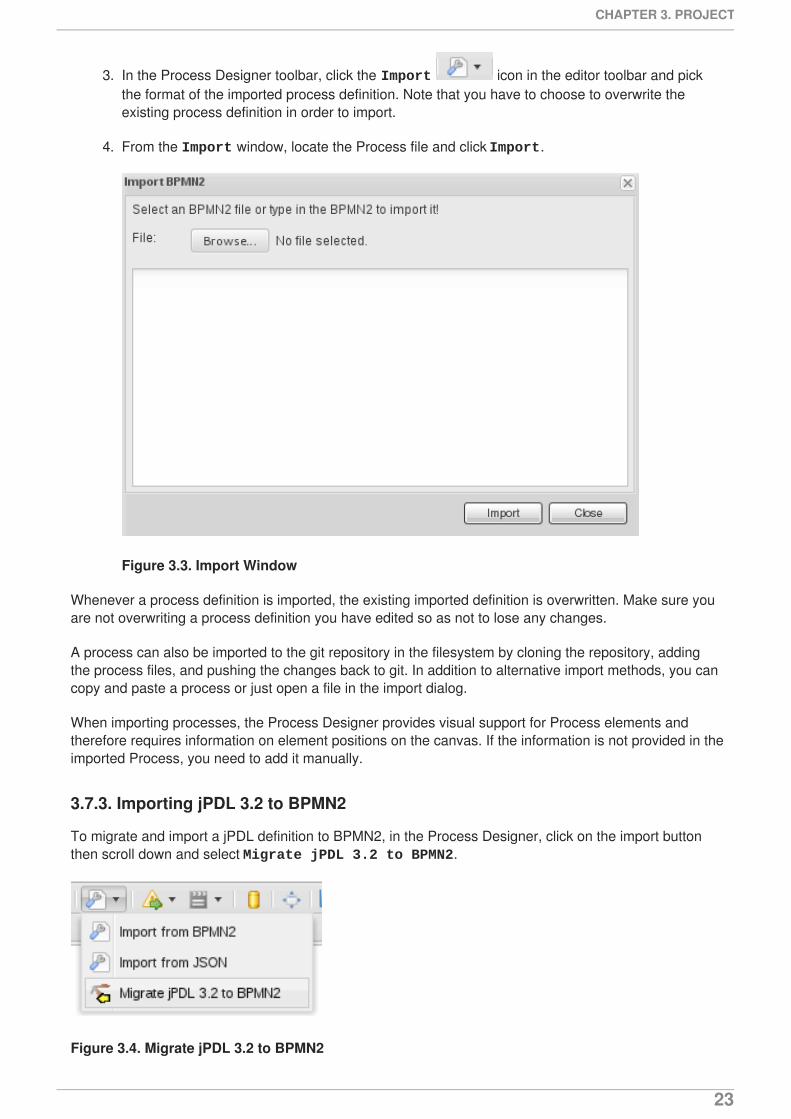
3. In the Process Designer toolbar, click the Import icon in the editor toolbar and pickthe format of the imported process definition. Note that you have to choose to overwrite theexisting process definition in order to import.
4. From the Import window, locate the Process file and click Import.
Figure 3.3. Import Window
Whenever a process definition is imported, the existing imported definition is overwritten. Make sure youare not overwriting a process definition you have edited so as not to lose any changes.
A process can also be imported to the git repository in the filesystem by cloning the repository, addingthe process files, and pushing the changes back to git. In addition to alternative import methods, you cancopy and paste a process or just open a file in the import dialog.
When importing processes, the Process Designer provides visual support for Process elements andtherefore requires information on element positions on the canvas. If the information is not provided in theimported Process, you need to add it manually.
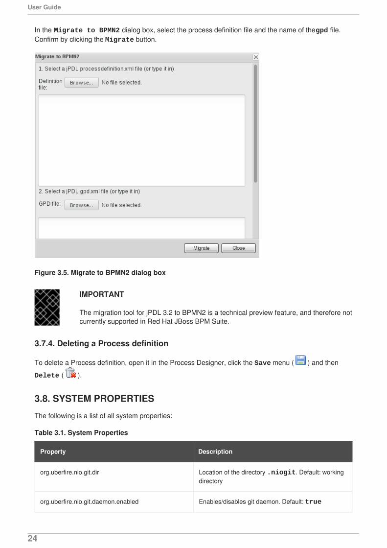
3.7.3. Importing jPDL 3.2 to BPMN2
To migrate and import a jPDL definition to BPMN2, in the Process Designer, click on the import buttonthen scroll down and select Migrate jPDL 3.2 to BPMN2.
Figure 3.4. Migrate jPDL 3.2 to BPMN2
CHAPTER 3. PROJECT
23
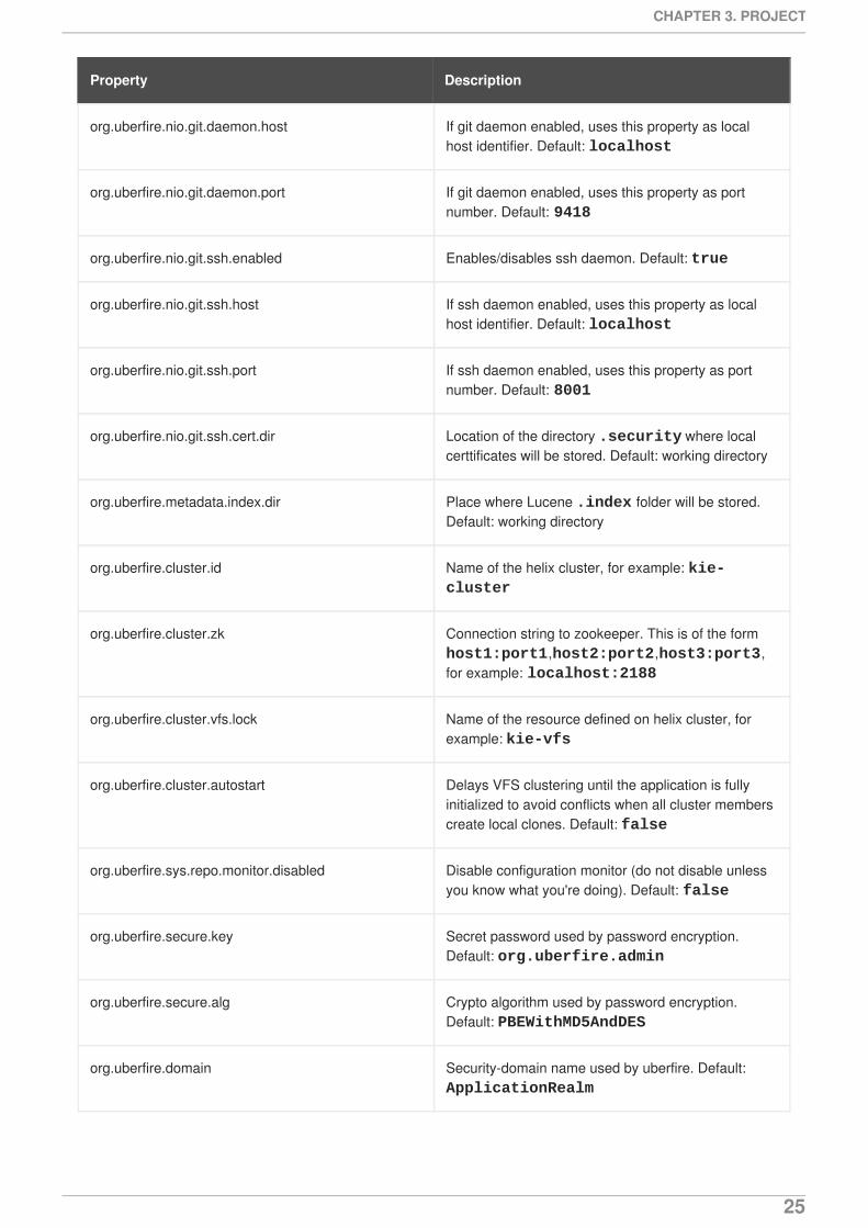
In the Migrate to BPMN2 dialog box, select the process definition file and the name of the gpd file.Confirm by clicking the Migrate button.
Figure 3.5. Migrate to BPMN2 dialog box
IMPORTANT
The migration tool for jPDL 3.2 to BPMN2 is a technical preview feature, and therefore notcurrently supported in Red Hat JBoss BPM Suite.
3.7.4. Deleting a Process definition
To delete a Process definition, open it in the Process Designer, click the Save menu ( ) and then
Delete ( ).
3.8. SYSTEM PROPERTIES
The following is a list of all system properties:
Table 3.1. System Properties
Property Description
org.uberfire.nio.git.dir Location of the directory .niogit. Default: workingdirectory
org.uberfire.nio.git.daemon.enabled Enables/disables git daemon. Default: true
User Guide
24
org.uberfire.nio.git.daemon.host If git daemon enabled, uses this property as localhost identifier. Default: localhost
org.uberfire.nio.git.daemon.port If git daemon enabled, uses this property as portnumber. Default: 9418
org.uberfire.nio.git.ssh.enabled Enables/disables ssh daemon. Default: true
org.uberfire.nio.git.ssh.host If ssh daemon enabled, uses this property as localhost identifier. Default: localhost
org.uberfire.nio.git.ssh.port If ssh daemon enabled, uses this property as portnumber. Default: 8001
org.uberfire.nio.git.ssh.cert.dir Location of the directory .security where localcerttificates will be stored. Default: working directory
org.uberfire.metadata.index.dir Place where Lucene .index folder will be stored.Default: working directory
org.uberfire.cluster.id Name of the helix cluster, for example: kie-cluster
org.uberfire.cluster.zk Connection string to zookeeper. This is of the form host1:port1,host2:port2,host3:port3,for example: localhost:2188
org.uberfire.cluster.vfs.lock Name of the resource defined on helix cluster, forexample: kie-vfs
org.uberfire.cluster.autostart Delays VFS clustering until the application is fullyinitialized to avoid conflicts when all cluster memberscreate local clones. Default: false
org.uberfire.sys.repo.monitor.disabled Disable configuration monitor (do not disable unlessyou know what you're doing). Default: false
org.uberfire.secure.key Secret password used by password encryption.Default: org.uberfire.admin
org.uberfire.secure.alg Crypto algorithm used by password encryption.Default: PBEWithMD5AndDES
org.uberfire.domain Security-domain name used by uberfire. Default: ApplicationRealm
Property Description
CHAPTER 3. PROJECT
25
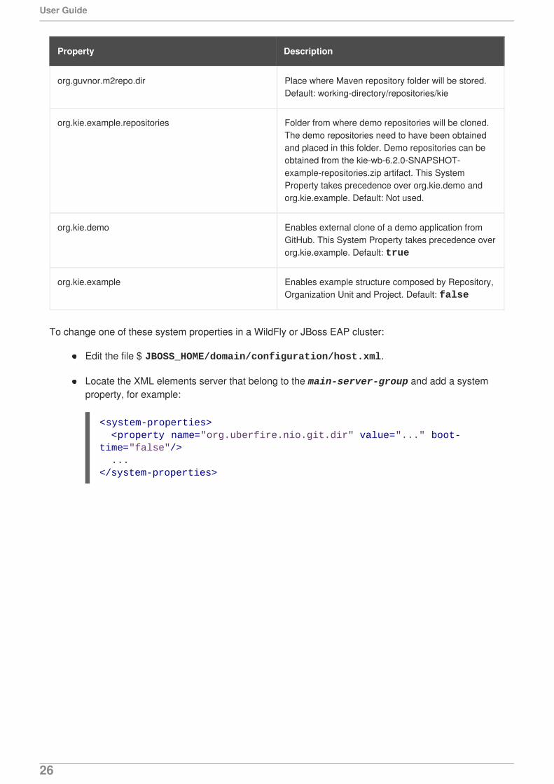
org.guvnor.m2repo.dir Place where Maven repository folder will be stored.Default: working-directory/repositories/kie
org.kie.example.repositories Folder from where demo repositories will be cloned.The demo repositories need to have been obtainedand placed in this folder. Demo repositories can beobtained from the kie-wb-6.2.0-SNAPSHOT-example-repositories.zip artifact. This SystemProperty takes precedence over org.kie.demo andorg.kie.example. Default: Not used.
org.kie.demo Enables external clone of a demo application fromGitHub. This System Property takes precedence overorg.kie.example. Default: true
org.kie.example Enables example structure composed by Repository,Organization Unit and Project. Default: false
Property Description
To change one of these system properties in a WildFly or JBoss EAP cluster:
Edit the file $ JBOSS_HOME/domain/configuration/host.xml.
Locate the XML elements server that belong to the main-server-group and add a systemproperty, for example:
<system-properties> <property name="org.uberfire.nio.git.dir" value="..." boot-time="false"/> ...</system-properties>
User Guide
26
CHAPTER 4. PROCESS DESIGNERThe Process Designer is the Red Hat JBoss BPM Suite process modeler. The output of the modeler is aBPMN 2.0 process definition file, which is saved in the Knowledge Repository, under normalcircumstances with a package of a project. The definition then serves as input for JBoss BPM SuiteProcess Engine, which creates a Process instance based on the definition.
The editor is delivered in two variants:
JBoss Developer Studio Process Designer
Thick-client version of the Process Designer integrated in the JBoss Developer Studio plug-in
Web Process Designer
Thin-client version of the Process Designer integrated in BPM Central
The graphical user interface of the Process Designer is the same for both the JBoss Developer StudioProcess Designer and the Web Process Designer.
The canvas represents the process diagram. Here you can place the elements from the palette which willconstitute the Process. Note that one Process definition may contain exactly one process diagram;therefore a Process definition equals to a Process diagram (this may differ in other products).
The Object Library (palette) contains groups of BPMN2 elements. Details on execution semantics andproperties of individual BPMN2 shapes are available in Appendix A, Process Elements.
The Properties panel displays the properties of the selected element. If no element is selected, the panelcontains Process properties.
The editor toolbar allows you to select an operation to be applied to the Elements on the canvas.
Figure 4.1. Process Designer environment
CHAPTER 4. PROCESS DESIGNER
27
NOTE
To enlarge the Process Designer screen (or any screen while working in Business Central), click on the
button shown here: . This will make your current editor fill the entireBusiness Central screen. To go back, simply click the button again.
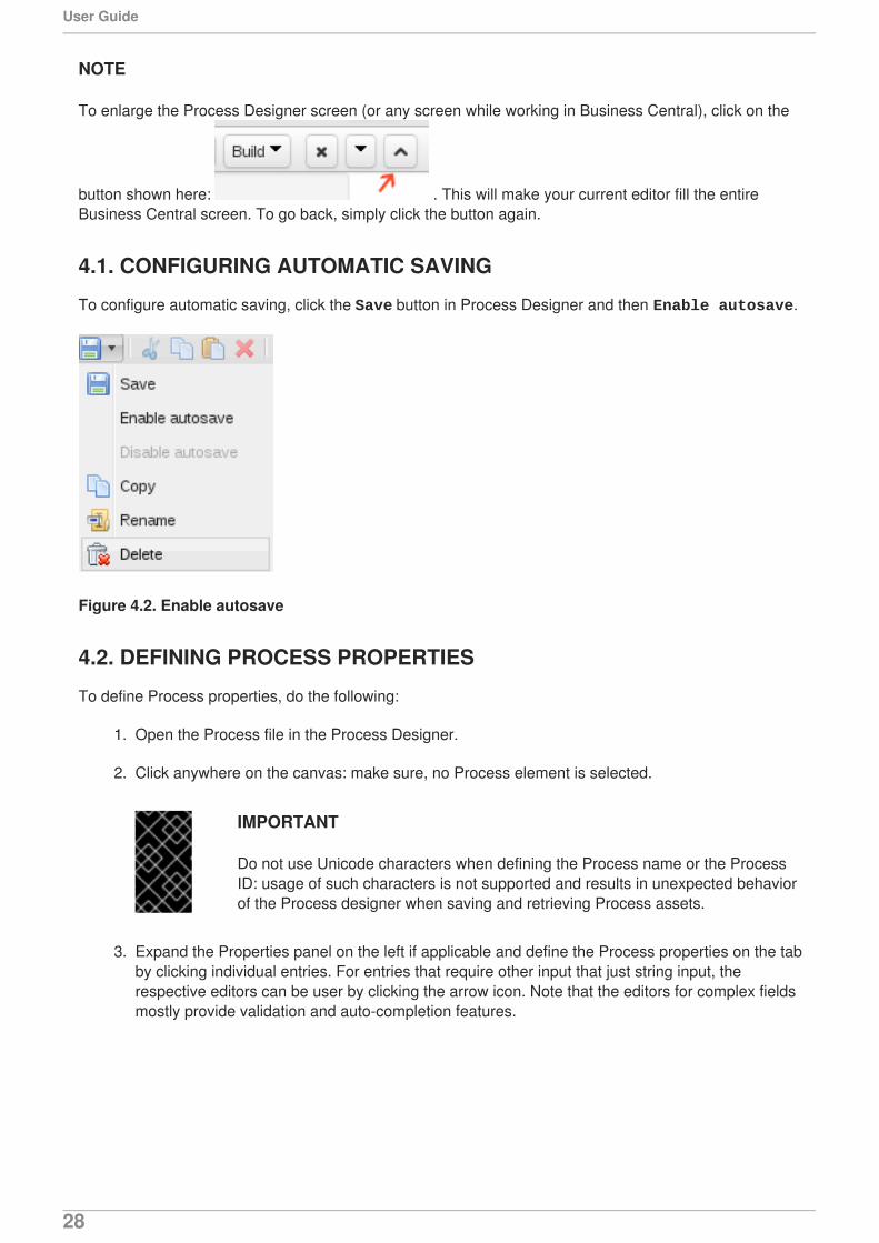
4.1. CONFIGURING AUTOMATIC SAVING
To configure automatic saving, click the Save button in Process Designer and then Enable autosave.
Figure 4.2. Enable autosave
4.2. DEFINING PROCESS PROPERTIES
To define Process properties, do the following:
1. Open the Process file in the Process Designer.
2. Click anywhere on the canvas: make sure, no Process element is selected.
IMPORTANT
Do not use Unicode characters when defining the Process name or the ProcessID: usage of such characters is not supported and results in unexpected behaviorof the Process designer when saving and retrieving Process assets.
3. Expand the Properties panel on the left if applicable and define the Process properties on the tabby clicking individual entries. For entries that require other input that just string input, therespective editors can be user by clicking the arrow icon. Note that the editors for complex fieldsmostly provide validation and auto-completion features.
User Guide
28
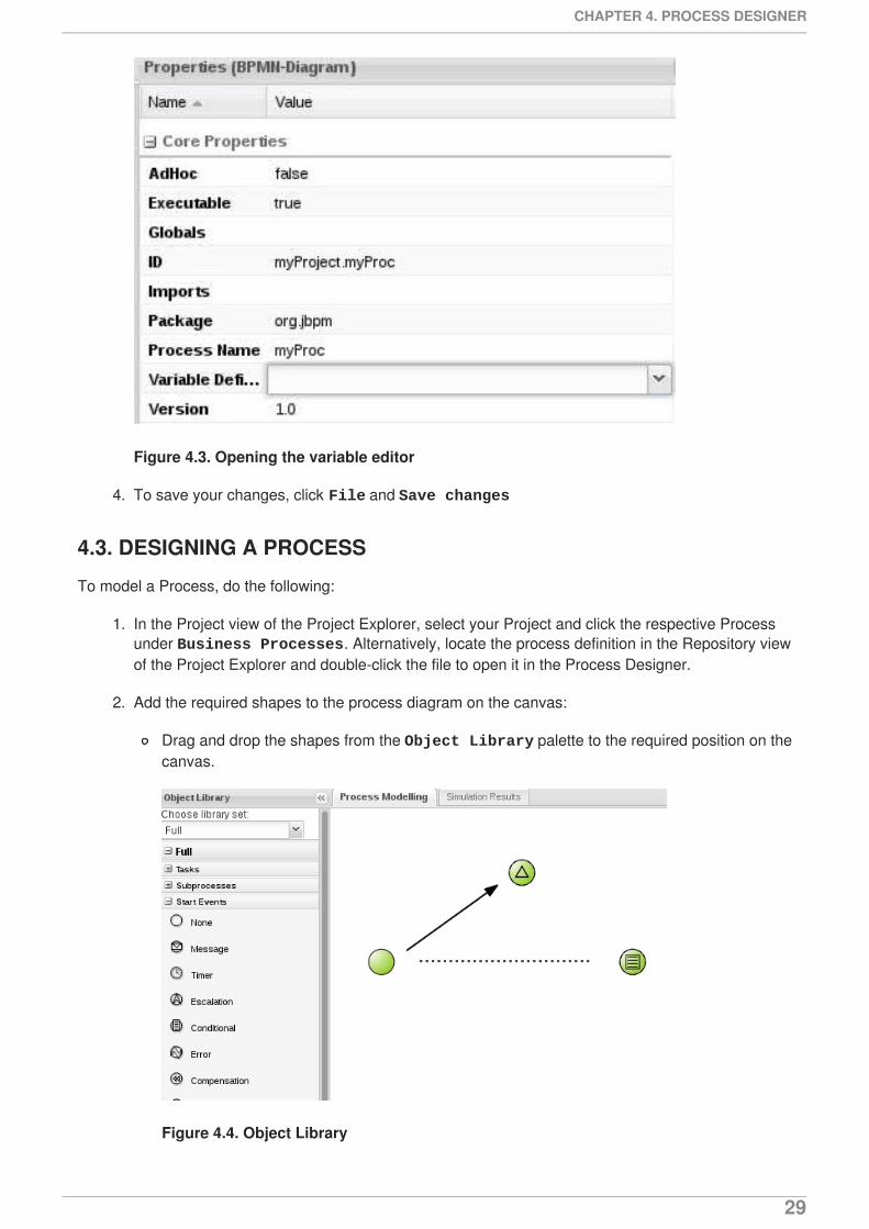
Figure 4.3. Opening the variable editor
4. To save your changes, click File and Save changes
4.3. DESIGNING A PROCESS
To model a Process, do the following:
1. In the Project view of the Project Explorer, select your Project and click the respective Processunder Business Processes. Alternatively, locate the process definition in the Repository viewof the Project Explorer and double-click the file to open it in the Process Designer.
2. Add the required shapes to the process diagram on the canvas:
Drag and drop the shapes from the Object Library palette to the required position on thecanvas.
Figure 4.4. Object Library
CHAPTER 4. PROCESS DESIGNER
29
Select a shape already placed on the canvas: the quick linker menu appears. The quicklinker feature displays only the elements that can be connected to the selected shape andconnects them with a valid Association element.
NOTE
To change the type of an already placed element to an element that extends
this element, click it and select the Morph shape ( ) icon.
3. Double-click an element to provide its Name. Consider defining the element properties in theProperties view.
4. Repeat the previous step until the Process Diagram defines the required workflow.
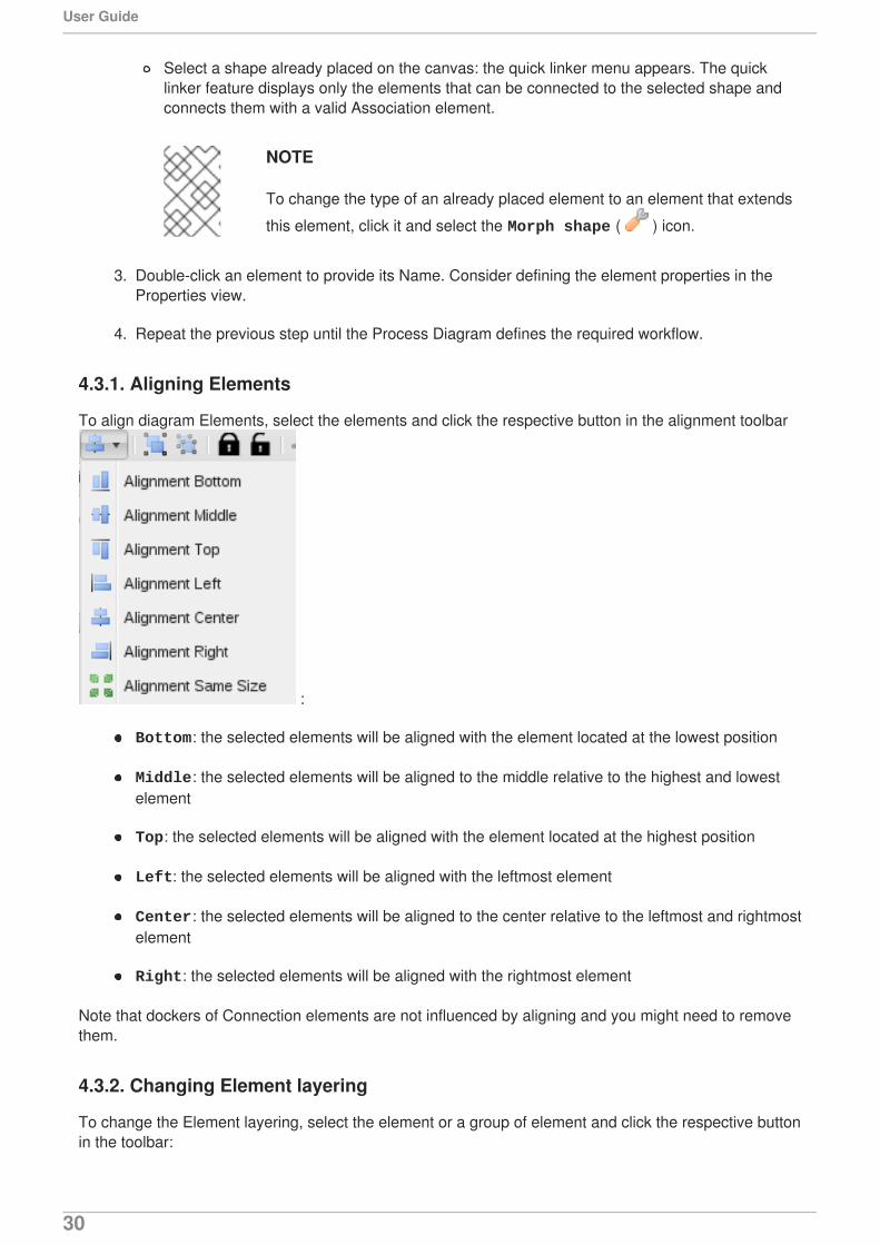
4.3.1. Aligning Elements
To align diagram Elements, select the elements and click the respective button in the alignment toolbar
:
Bottom: the selected elements will be aligned with the element located at the lowest position
Middle: the selected elements will be aligned to the middle relative to the highest and lowestelement
Top: the selected elements will be aligned with the element located at the highest position
Left: the selected elements will be aligned with the leftmost element
Center: the selected elements will be aligned to the center relative to the leftmost and rightmostelement
Right: the selected elements will be aligned with the rightmost element
Note that dockers of Connection elements are not influenced by aligning and you might need to removethem.
4.3.2. Changing Element layering
To change the Element layering, select the element or a group of element and click the respective buttonin the toolbar:
User Guide
30
Bring To Front : bring the selected element to foreground to the uppermost layer
Bring To Back : send the selected element to background to the lowest layer
Bring Forward : bring the selected element to foreground by one layer
Bring Backward : send the selected element to background by one layer
Center : the selected elements will be aligned to the center relative to the leftmost and rightmostelement
Right : the selected elements will be aligned with the rightmost element
Note that Connection Elements are not influenced by layering and remain always visible.
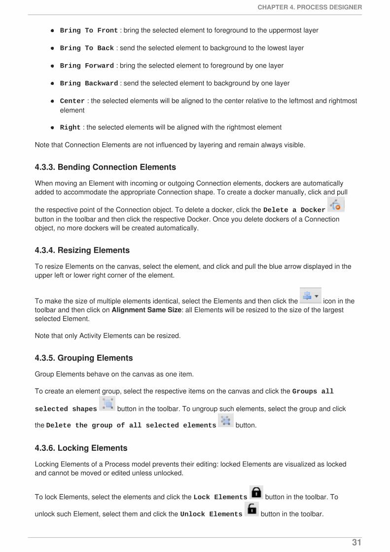
4.3.3. Bending Connection Elements
When moving an Element with incoming or outgoing Connection elements, dockers are automaticallyadded to accommodate the appropriate Connection shape. To create a docker manually, click and pull
the respective point of the Connection object. To delete a docker, click the Delete a Docker button in the toolbar and then click the respective Docker. Once you delete dockers of a Connectionobject, no more dockers will be created automatically.
4.3.4. Resizing Elements
To resize Elements on the canvas, select the element, and click and pull the blue arrow displayed in theupper left or lower right corner of the element.
To make the size of multiple elements identical, select the Elements and then click the icon in thetoolbar and then click on Alignment Same Size: all Elements will be resized to the size of the largestselected Element.
Note that only Activity Elements can be resized.
4.3.5. Grouping Elements
Group Elements behave on the canvas as one item.
To create an element group, select the respective items on the canvas and click the Groups all
selected shapes button in the toolbar. To ungroup such elements, select the group and click
the Delete the group of all selected elements button.
4.3.6. Locking Elements
Locking Elements of a Process model prevents their editing: locked Elements are visualized as lockedand cannot be moved or edited unless unlocked.
To lock Elements, select the elements and click the Lock Elements button in the toolbar. To
unlock such Element, select them and click the Unlock Elements button in the toolbar.
CHAPTER 4. PROCESS DESIGNER
31
4.3.7. Changing the color scheme
Color schemes define the color used for individual Process Elements in its diagram.
Color schemes are stored in the themes.json file, which is located in the global directory of eachrepository.
Procedure 4.1. Creating a new color schema
1. Locate your project in the Project Explorer and switch to the Repository view.
2. Open the global directory and locate and open the themes.json file.
3. In the displayed Default Editor, add your theme definition at the end of the file and click the Savebutton.
To apply a new color scheme or any other defined scheme, in the Process Designer, click the Color
Scheme button in the toolbar and select the respective color scheme from the drop-down menu.
4.3.8. Recording local history
Local history keeps track of any changes, you apply to your Process model so as to allow you to restoreany previous status of the Process model. By default, this feature is turned off.
To turn on local history recording, click the Local History button and select Enable Local History entry. From this menu, you can also display the local history records and apply the respectivestatus to the Process as well as disable the feature or clear the current local history log.
4.3.9. Enlarging and shrinking canvas
To change the size of the canvas, click the respective yellow arrow on the canvas edge.
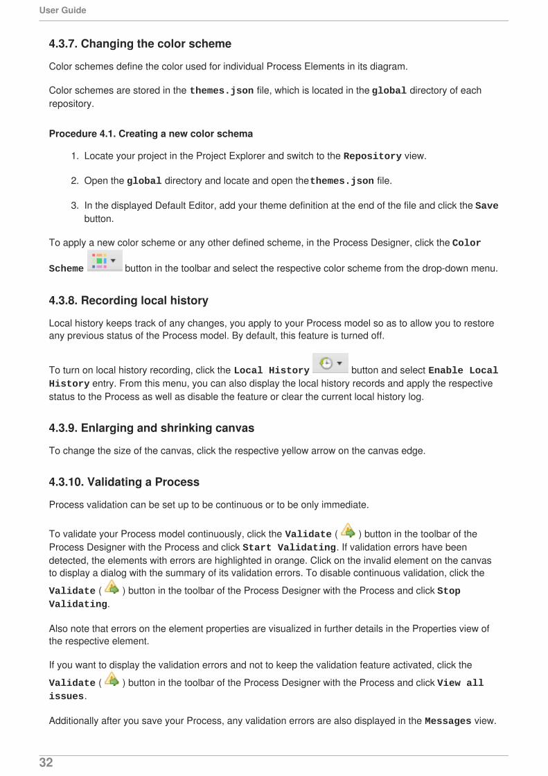
4.3.10. Validating a Process
Process validation can be set up to be continuous or to be only immediate.
To validate your Process model continuously, click the Validate ( ) button in the toolbar of theProcess Designer with the Process and click Start Validating. If validation errors have beendetected, the elements with errors are highlighted in orange. Click on the invalid element on the canvasto display a dialog with the summary of its validation errors. To disable continuous validation, click the
Validate ( ) button in the toolbar of the Process Designer with the Process and click Stop Validating.
Also note that errors on the element properties are visualized in further details in the Properties view ofthe respective element.
If you want to display the validation errors and not to keep the validation feature activated, click the
Validate ( ) button in the toolbar of the Process Designer with the Process and click View all issues.
Additionally after you save your Process, any validation errors are also displayed in the Messages view.
User Guide
32
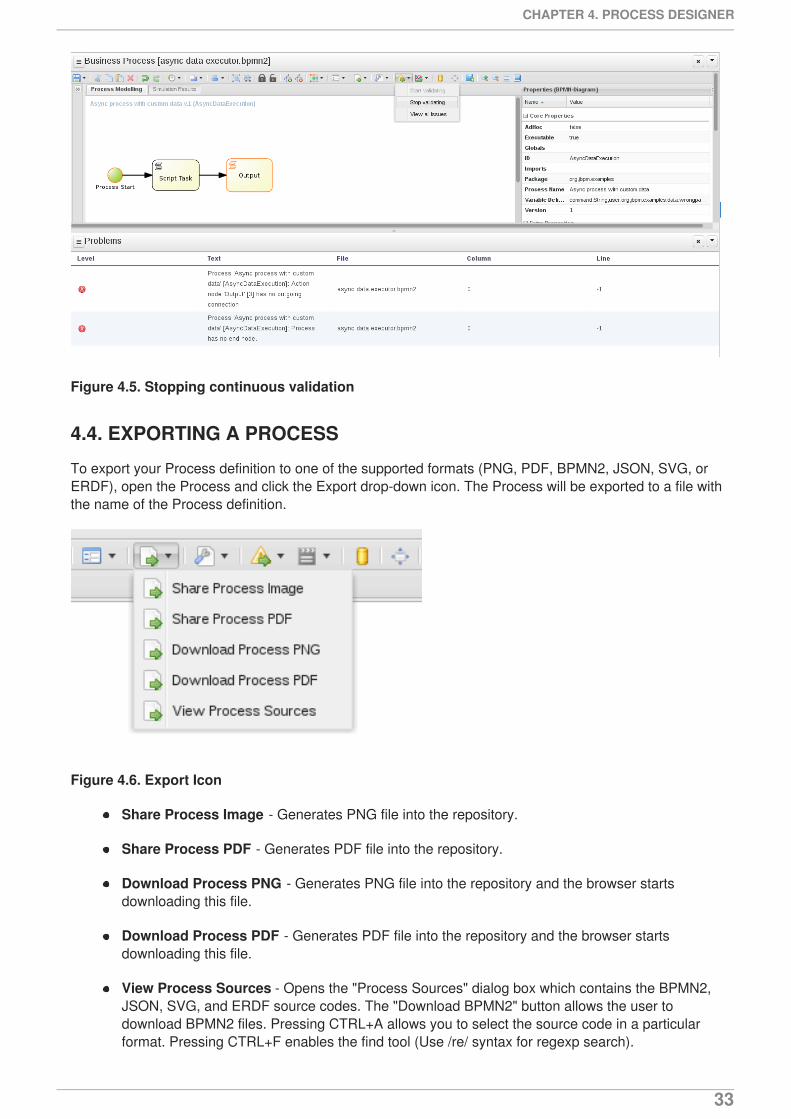
Figure 4.5. Stopping continuous validation
4.4. EXPORTING A PROCESS
To export your Process definition to one of the supported formats (PNG, PDF, BPMN2, JSON, SVG, orERDF), open the Process and click the Export drop-down icon. The Process will be exported to a file withthe name of the Process definition.
Figure 4.6. Export Icon
Share Process Image - Generates PNG file into the repository.
Share Process PDF - Generates PDF file into the repository.
Download Process PNG - Generates PNG file into the repository and the browser startsdownloading this file.
Download Process PDF - Generates PDF file into the repository and the browser startsdownloading this file.
View Process Sources - Opens the "Process Sources" dialog box which contains the BPMN2,JSON, SVG, and ERDF source codes. The "Download BPMN2" button allows the user todownload BPMN2 files. Pressing CTRL+A allows you to select the source code in a particularformat. Pressing CTRL+F enables the find tool (Use /re/ syntax for regexp search).
CHAPTER 4. PROCESS DESIGNER
33
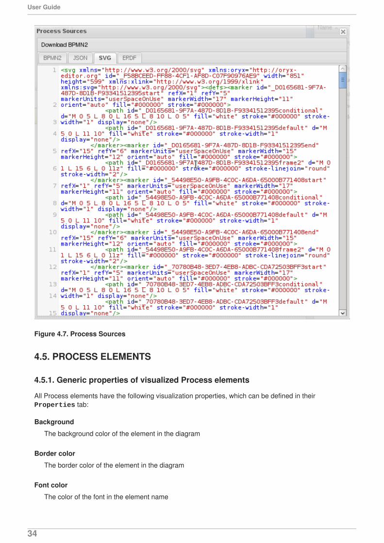
Figure 4.7. Process Sources
4.5. PROCESS ELEMENTS
4.5.1. Generic properties of visualized Process elements
All Process elements have the following visualization properties, which can be defined in their Properties tab:
Background
The background color of the element in the diagram
Border color
The border color of the element in the diagram
Font color
The color of the font in the element name
User Guide
34
Font size
The size of the font in the element name
Name
The element name displayed on the BPMN diagram
4.5.2. Defining Process elements properties
All Process Elements, including the Process, define a set of properties that define the following:
Core properties, which include the basic properties of an element (typically Name, Data Set,Scripts, etc.).
Extra properties, which include the properties necessary for the element execution (refer toSection A.6, “Process Elements”), data mapping (variable mapping) and local variable definitions(see Section 4.8.1, “Globals”), properties that represent an extension of the jBPM engine,typically onExitAction, Documentation, etc.
Graphical properties, which include graphical representation of elements (colors, textsettings).
Simulation properties are used by the Simulation engine.
In element properties of the String type can use #{expression} to embed a value. The value will beretrieved on element instantiation, and the substitution expression will be replaced with the result ofcalling the toString() method on the variable defined in the expression. The expression could be thename of a variable (in which case it resolves to the value of the variable), but more advanced MVELexpressions are possible as well, e.g., #{person.name.firstname}.
To define Element properties, do the following:
1. Open the Process definition in the Process Designer:
2. On the canvas, select the Element.
3. Click the double arrow ( ) in the upper left corner of the Process Designer to display the Properties view.
4. In the displayed Properties view, click the property value fields to edit them. Note that whereapplicable, you can click the drop-down arrow and the relevant value editor appears in a newdialog box.
5. To save your changes, click the Save icon and select option Save.
4.6. FORMS
A form is a layout definition for a page (defined as HTML) that is displayed as a dialog window to theuser on a
process instantiation or a
task instantiation.
CHAPTER 4. PROCESS DESIGNER
35
The form is then respectively referred to as a Process form or a Task form. It serves for acquiringdata for the Element instance execution, be it a Process or Task, from a human user: a Process formcan take as its input and output Process variables; a Task form can take as its input DataInputSetvariables with assignment defined, and as its output DataOutputSet variables with assignment defined.
For example, you could ask the user to provide the input parameters needed for Process instantiationand display any variable data connected to the Process; or using a Human Task show information andrequest input for further Process execution.
This data can be mapped to the Task as DataInputSet and used as the Task's local variables and toDataOutputSet to provide the data to the parent Process instance (refer to Section 4.11, “Assignment”).
4.6.1. Defining Process form
A Process form is a form that is displayed at Process instantiation to the user who instantiated theProcess.
To create a Process form, do the following:
1. Open your Process definition in the Process Designer.
2. In the editor toolbar, click the Form ( ) icon and then Edit Process Form.
3. Select the editor to use to edit the form. Note that this document deals only with the Graphical Modeler option.
Note that the Form is created in the root of your current Project and is available from any other Processdefinitions in the Projects.
4.6.2. Defining Task form
A Task form is a form that is displayed at User Task instantiation, that is, when the execution flowreaches the Task, to the Actor of the User Task.
To create a Task form, do the following:
1. Open your Process definition with the User Task in the Process Designer.
2. Select the Task on the canvas and click the Edit Process Form ( ) in the User Taskmenu.
3. In the displayed Form Editor, define the Task form.
4.6.3. Defining form fields
Once you have created a form definition, you need to define its content: that is its fields and the data theyare bound to. You can add either the pre-defined field types to your form, or define your own data originand use the custom field types in your form definition.
NOTE
Automatic form generation is not recursive, which means that when custom data objectsare used, only the top-level form is generated (no subforms). The user is responsible forcreating forms that represent the custom data objects and link them to the parent form.
User Guide
36
4.7. FORM MODELER
Red Hat JBoss BPM Suite provides a custom editor for defining forms called Form Modeler.
Form Modeler includes the following key features:
Form Modeling WYSIWYG UI for forms
Form autogeneration from data model / Java objects
Data binding for Java objects
Formula and expressions
Customized forms layouts
Forms embedding
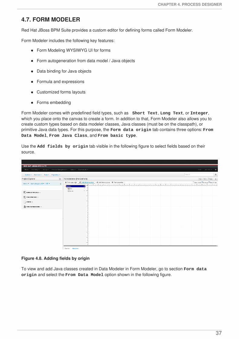
Form Modeler comes with predefined field types, such as Short Text, Long Text, or Integer,which you place onto the canvas to create a form. In addition to that, Form Modeler also allows you tocreate custom types based on data modeler classes, Java classes (must be on the classpath), orprimitive Java data types. For this purpose, the Form data origin tab contains three options: From Data Model, From Java Class, and From basic type.
Use the Add fields by origin tab visible in the following figure to select fields based on theirsource.
Figure 4.8. Adding fields by origin
To view and add Java classes created in Data Modeler in Form Modeler, go to section Form data origin and select the From Data Model option shown in the following figure.
CHAPTER 4. PROCESS DESIGNER
37
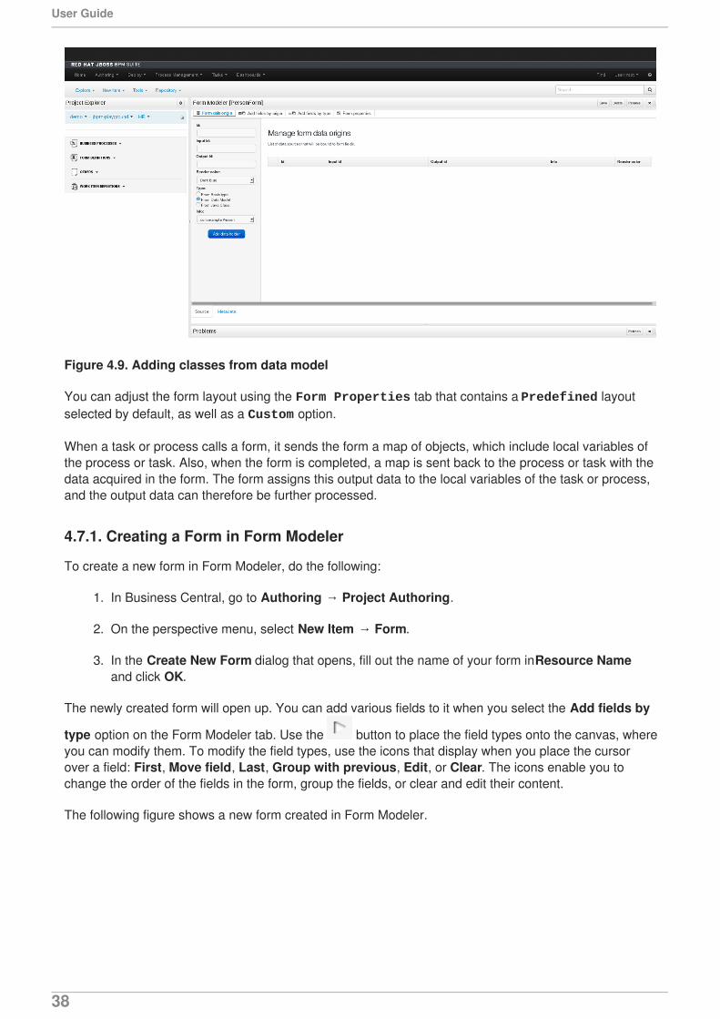
Figure 4.9. Adding classes from data model
You can adjust the form layout using the Form Properties tab that contains a Predefined layoutselected by default, as well as a Custom option.
When a task or process calls a form, it sends the form a map of objects, which include local variables ofthe process or task. Also, when the form is completed, a map is sent back to the process or task with thedata acquired in the form. The form assigns this output data to the local variables of the task or process,and the output data can therefore be further processed.
4.7.1. Creating a Form in Form Modeler
To create a new form in Form Modeler, do the following:
1. In Business Central, go to Authoring → Project Authoring.
2. On the perspective menu, select New Item → Form.
3. In the Create New Form dialog that opens, fill out the name of your form in Resource Nameand click OK.
The newly created form will open up. You can add various fields to it when you select the Add fields by
type option on the Form Modeler tab. Use the button to place the field types onto the canvas, whereyou can modify them. To modify the field types, use the icons that display when you place the cursorover a field: First, Move field, Last, Group with previous, Edit, or Clear. The icons enable you tochange the order of the fields in the form, group the fields, or clear and edit their content.
The following figure shows a new form created in Form Modeler.
User Guide
38
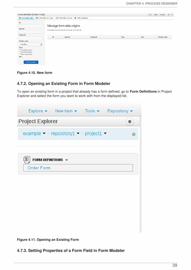
Figure 4.10. New form
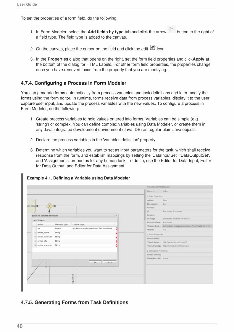
4.7.2. Opening an Existing Form in Form Modeler
To open an existing form in a project that already has a form defined, go to Form Definitions in ProjectExplorer and select the form you want to work with from the displayed list.
Figure 4.11. Opening an Existing Form
4.7.3. Setting Properties of a Form Field in Form Modeler
CHAPTER 4. PROCESS DESIGNER
39
To set the properties of a form field, do the following:
1. In Form Modeler, select the Add fields by type tab and click the arrow button to the right ofa field type. The field type is added to the canvas.
2. On the canvas, place the cursor on the field and click the edit icon.
3. In the Properties dialog that opens on the right, set the form field properties and click Apply atthe bottom of the dialog for HTML Labels. For other form field properties, the properties changeonce you have removed focus from the property that you are modifying.
4.7.4. Configuring a Process in Form Modeler
You can generate forms automatically from process variables and task definitions and later modify theforms using the form editor. In runtime, forms receive data from process variables, display it to the user,capture user input, and update the process variables with the new values. To configure a process inForm Modeler, do the following:
1. Create process variables to hold values entered into forms. Variables can be simple (e.g.'string') or complex. You can define complex variables using Data Modeler, or create them inany Java integrated development environment (Java IDE) as regular plain Java objects.
2. Declare the process variables in the 'variables definition' property.
3. Determine which variables you want to set as input parameters for the task, which shall receiveresponse from the form, and establish mappings by setting the 'DataInputSet', 'DataOutputSet',and 'Assignments' properties for any human task. To do so, use the Editor for Data Input, Editorfor Data Output, and Editor for Data Assignment.
Example 4.1. Defining a Variable using Data Modeler
4.7.5. Generating Forms from Task Definitions
User Guide
40
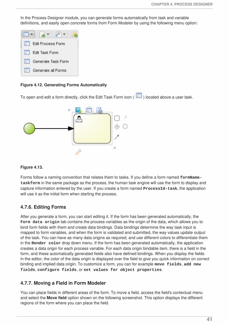
In the Process Designer module, you can generate forms automatically from task and variabledefinitions, and easily open concrete forms from Form Modeler by using the following menu option:
Figure 4.12. Generating Forms Automatically
To open and edit a form directly, click the Edit Task Form icon ( ) located above a user task.
Figure 4.13.
Forms follow a naming convention that relates them to tasks. If you define a form named formName-taskform in the same package as the process, the human task engine will use the form to display andcapture information entered by the user. If you create a form named ProcessId-task, the applicationwill use it as the initial form when starting the process.
4.7.6. Editing Forms
After you generate a form, you can start editing it. If the form has been generated automatically, the Form data origin tab contains the process variables as the origin of the data, which allows you tobind form fields with them and create data bindings. Data bindings determine the way task input ismapped to form variables, and when the form is validated and submitted, the way values update outputof the task. You can have as many data origins as required, and use different colors to differentiate themin the Render color drop down menu. If the form has been generated automatically, the applicationcreates a data origin for each process variable. For each data origin bindable item, there is a field in theform, and these automatically generated fields also have defined bindings. When you display the fieldsin the editor, the color of the data origin is displayed over the field to give you quick information on correctbinding and implied data origin. To customize a form, you can for example move fields, add new fields, configure fields, or set values for object properties.
4.7.7. Moving a Field in Form Modeler
You can place fields in different areas of the form. To move a field, access the field's contextual menuand select the Move field option shown on the following screenshot. This option displays the differentregions of the form where you can place the field.
CHAPTER 4. PROCESS DESIGNER
41
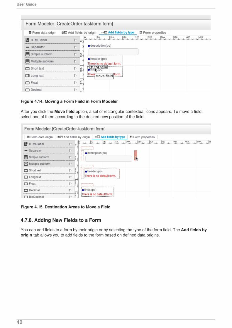
Figure 4.14. Moving a Form Field in Form Modeler
After you click the Move field option, a set of rectangular contextual icons appears. To move a field,select one of them according to the desired new position of the field.
Figure 4.15. Destination Areas to Move a Field
4.7.8. Adding New Fields to a Form
You can add fields to a form by their origin or by selecting the type of the form field. The Add fields byorigin tab allows you to add fields to the form based on defined data origins.
User Guide
42
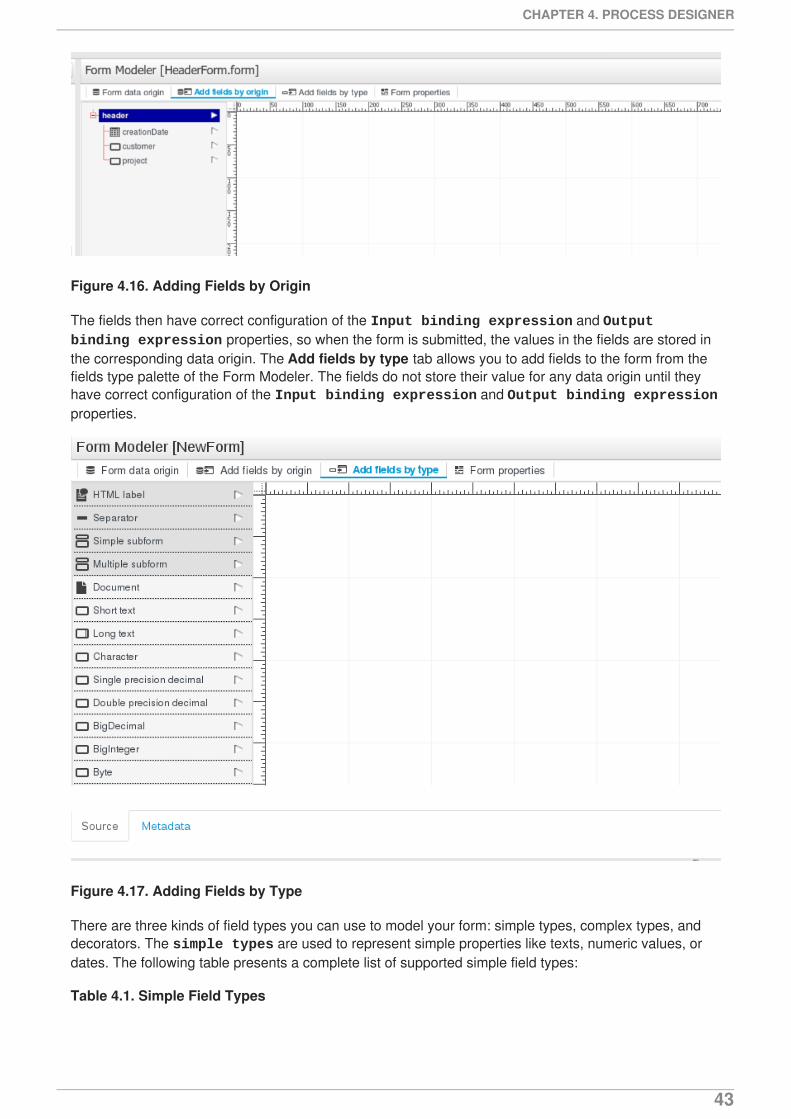
Figure 4.16. Adding Fields by Origin
The fields then have correct configuration of the Input binding expression and Output binding expression properties, so when the form is submitted, the values in the fields are stored inthe corresponding data origin. The Add fields by type tab allows you to add fields to the form from thefields type palette of the Form Modeler. The fields do not store their value for any data origin until theyhave correct configuration of the Input binding expression and Output binding expressionproperties.
Figure 4.17. Adding Fields by Type
There are three kinds of field types you can use to model your form: simple types, complex types, anddecorators. The simple types are used to represent simple properties like texts, numeric values, ordates. The following table presents a complete list of supported simple field types:
Table 4.1. Simple Field Types
CHAPTER 4. PROCESS DESIGNER
43
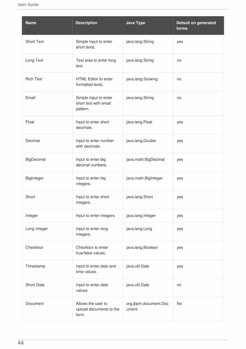
Name Description Java Type Default on generatedforms
Short Text Simple input to entershort texts.
java.lang.String yes
Long Text Text area to enter longtext.
java.lang.String no
Rich Text HTML Editor to enterformatted texts.
java.lang.Srowing no
Email Simple input to entershort text with emailpattern.
java.lang.String no
Float Input to enter shortdecimals.
java.lang.Float yes
Decimal Input to enter numberwith decimals.
java.lang.Double yes
BigDecimal Input to enter bigdecimal numbers.
java.math.BigDecimal yes
BigInteger Input to enter bigintegers.
java.math.BigInteger yes
Short Input to enter shortintegers.
java.lang.Short yes
Integer Input to enter integers. java.lang.Integer yes
Long Integer Input to enter longintegers.
java.lang.Long yes
Checkbox Checkbox to entertrue/false values.
java.lang.Boolean yes
Timestamp Input to enter date andtime values.
java.util.Date yes
Short Date Input to enter datevalues.
java.util.Date no
Document Allows the user toupload documents to theform.
org.jbpm.document.Document
No
User Guide
44
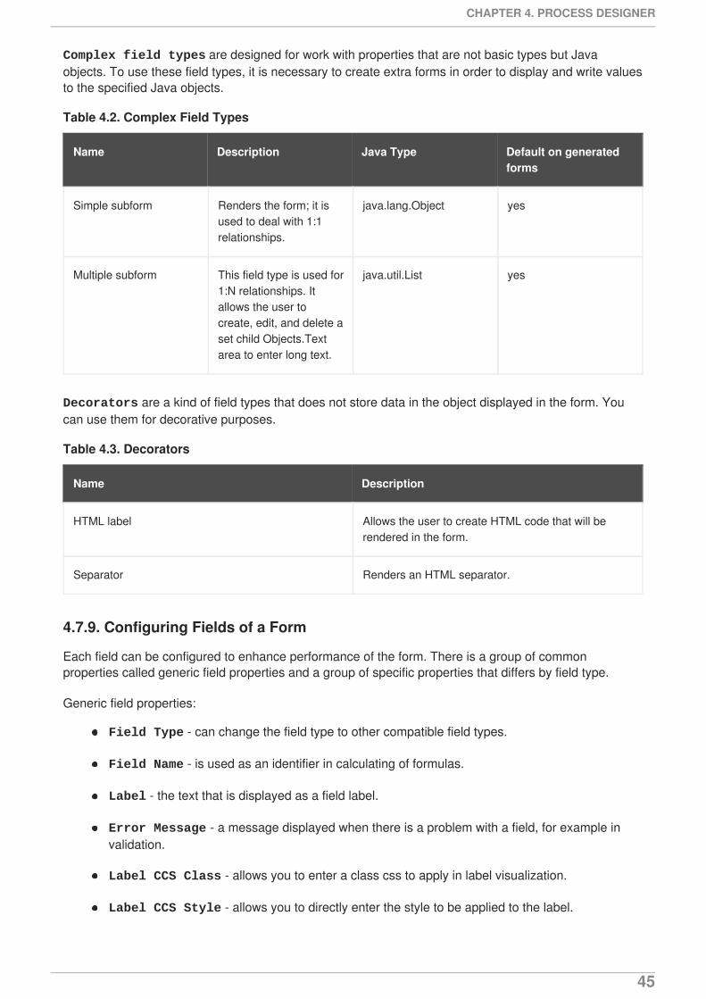
Complex field types are designed for work with properties that are not basic types but Javaobjects. To use these field types, it is necessary to create extra forms in order to display and write valuesto the specified Java objects.
Table 4.2. Complex Field Types
Name Description Java Type Default on generatedforms
Simple subform Renders the form; it isused to deal with 1:1relationships.
java.lang.Object yes
Multiple subform This field type is used for1:N relationships. Itallows the user tocreate, edit, and delete aset child Objects.Textarea to enter long text.
java.util.List yes
Decorators are a kind of field types that does not store data in the object displayed in the form. Youcan use them for decorative purposes.
Table 4.3. Decorators
Name Description
HTML label Allows the user to create HTML code that will berendered in the form.
Separator Renders an HTML separator.
4.7.9. Configuring Fields of a Form
Each field can be configured to enhance performance of the form. There is a group of commonproperties called generic field properties and a group of specific properties that differs by field type.
Generic field properties:
Field Type - can change the field type to other compatible field types.
Field Name - is used as an identifier in calculating of formulas.
Label - the text that is displayed as a field label.
Error Message - a message displayed when there is a problem with a field, for example invalidation.
Label CCS Class - allows you to enter a class css to apply in label visualization.
Label CCS Style - allows you to directly enter the style to be applied to the label.
CHAPTER 4. PROCESS DESIGNER
45
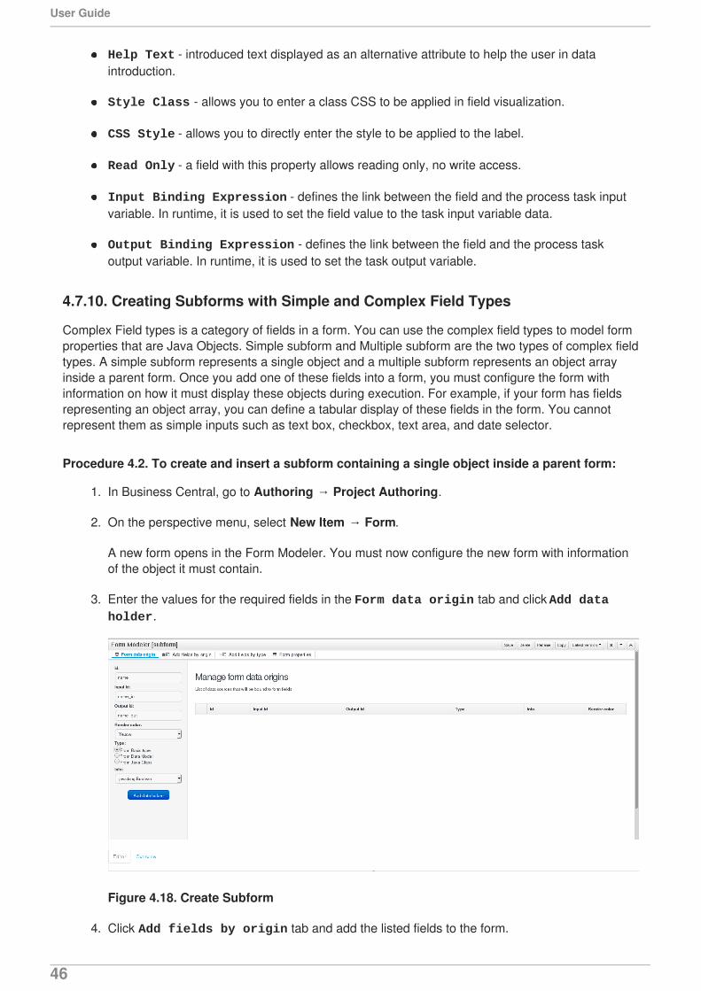
Help Text - introduced text displayed as an alternative attribute to help the user in dataintroduction.
Style Class - allows you to enter a class CSS to be applied in field visualization.
CSS Style - allows you to directly enter the style to be applied to the label.
Read Only - a field with this property allows reading only, no write access.
Input Binding Expression - defines the link between the field and the process task inputvariable. In runtime, it is used to set the field value to the task input variable data.
Output Binding Expression - defines the link between the field and the process taskoutput variable. In runtime, it is used to set the task output variable.
4.7.10. Creating Subforms with Simple and Complex Field Types
Complex Field types is a category of fields in a form. You can use the complex field types to model formproperties that are Java Objects. Simple subform and Multiple subform are the two types of complex fieldtypes. A simple subform represents a single object and a multiple subform represents an object arrayinside a parent form. Once you add one of these fields into a form, you must configure the form withinformation on how it must display these objects during execution. For example, if your form has fieldsrepresenting an object array, you can define a tabular display of these fields in the form. You cannotrepresent them as simple inputs such as text box, checkbox, text area, and date selector.
Procedure 4.2. To create and insert a subform containing a single object inside a parent form:
1. In Business Central, go to Authoring → Project Authoring.
2. On the perspective menu, select New Item → Form.
A new form opens in the Form Modeler. You must now configure the new form with informationof the object it must contain.
3. Enter the values for the required fields in the Form data origin tab and click Add data holder.
Figure 4.18. Create Subform
4. Click Add fields by origin tab and add the listed fields to the form.
User Guide
46

Figure 4.19. Add fields by origin
5. Click the Edit icon on the field in the form to open the Properties tab.
6. In the Properties tab, configure the form by providing required values to the fields and click Save to save the subform.
7. Open the parent form to configure the properties of the object.
8. In the parent form, click the Add fields by type tab. Select the object on the form andconfigure it in the Properties tab.
9. In the Properties tab, select Simple subform for the Field type property. Then selectthe newly created subform for the Default form field property.
Figure 4.20. Configure the Parent Form
10. Click Save to save the parent form.
This inserts your subform containing a single Java object inside the parent form.
Procedure 4.3. To insert a subform with multiple objects inside a parent form:
1. In Business Central, go to Authoring → Project Authoring.
CHAPTER 4. PROCESS DESIGNER
47
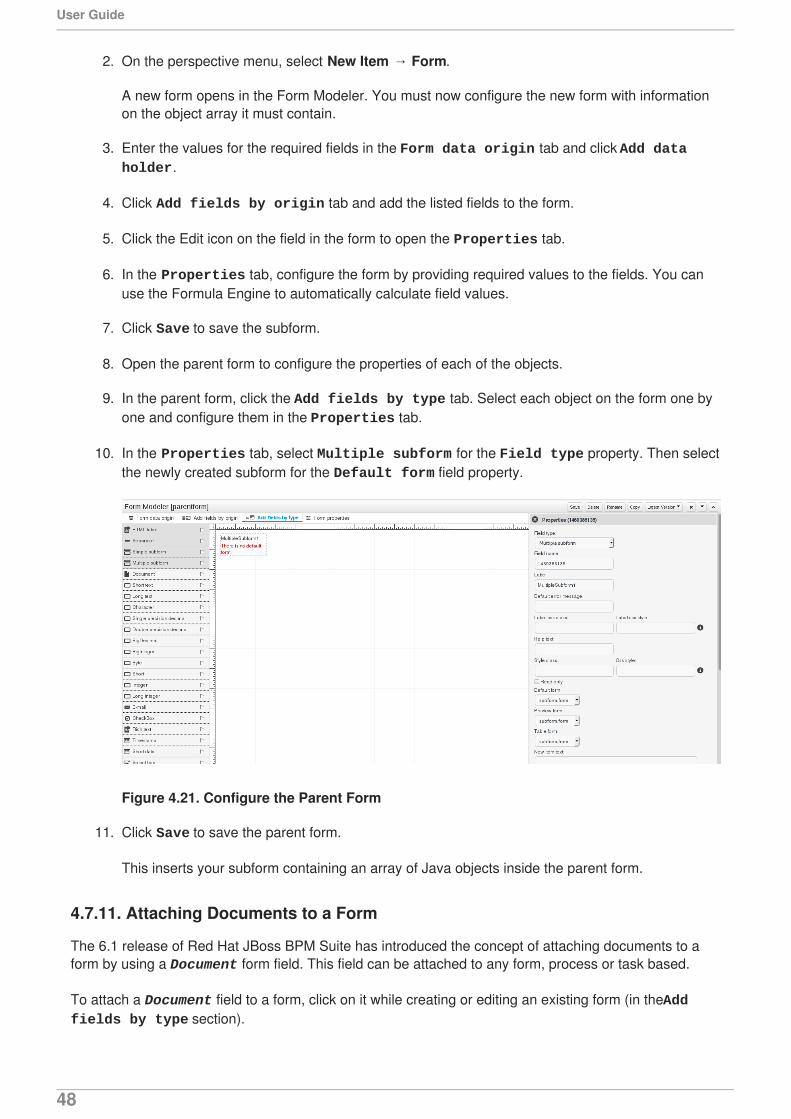
2. On the perspective menu, select New Item → Form.
A new form opens in the Form Modeler. You must now configure the new form with informationon the object array it must contain.
3. Enter the values for the required fields in the Form data origin tab and click Add data holder.
4. Click Add fields by origin tab and add the listed fields to the form.
5. Click the Edit icon on the field in the form to open the Properties tab.
6. In the Properties tab, configure the form by providing required values to the fields. You canuse the Formula Engine to automatically calculate field values.
7. Click Save to save the subform.
8. Open the parent form to configure the properties of each of the objects.
9. In the parent form, click the Add fields by type tab. Select each object on the form one byone and configure them in the Properties tab.
10. In the Properties tab, select Multiple subform for the Field type property. Then selectthe newly created subform for the Default form field property.
Figure 4.21. Configure the Parent Form
11. Click Save to save the parent form.
This inserts your subform containing an array of Java objects inside the parent form.
4.7.11. Attaching Documents to a Form
The 6.1 release of Red Hat JBoss BPM Suite has introduced the concept of attaching documents to aform by using a Document form field. This field can be attached to any form, process or task based.
To attach a Document field to a form, click on it while creating or editing an existing form (in the Add fields by type section).
User Guide
48
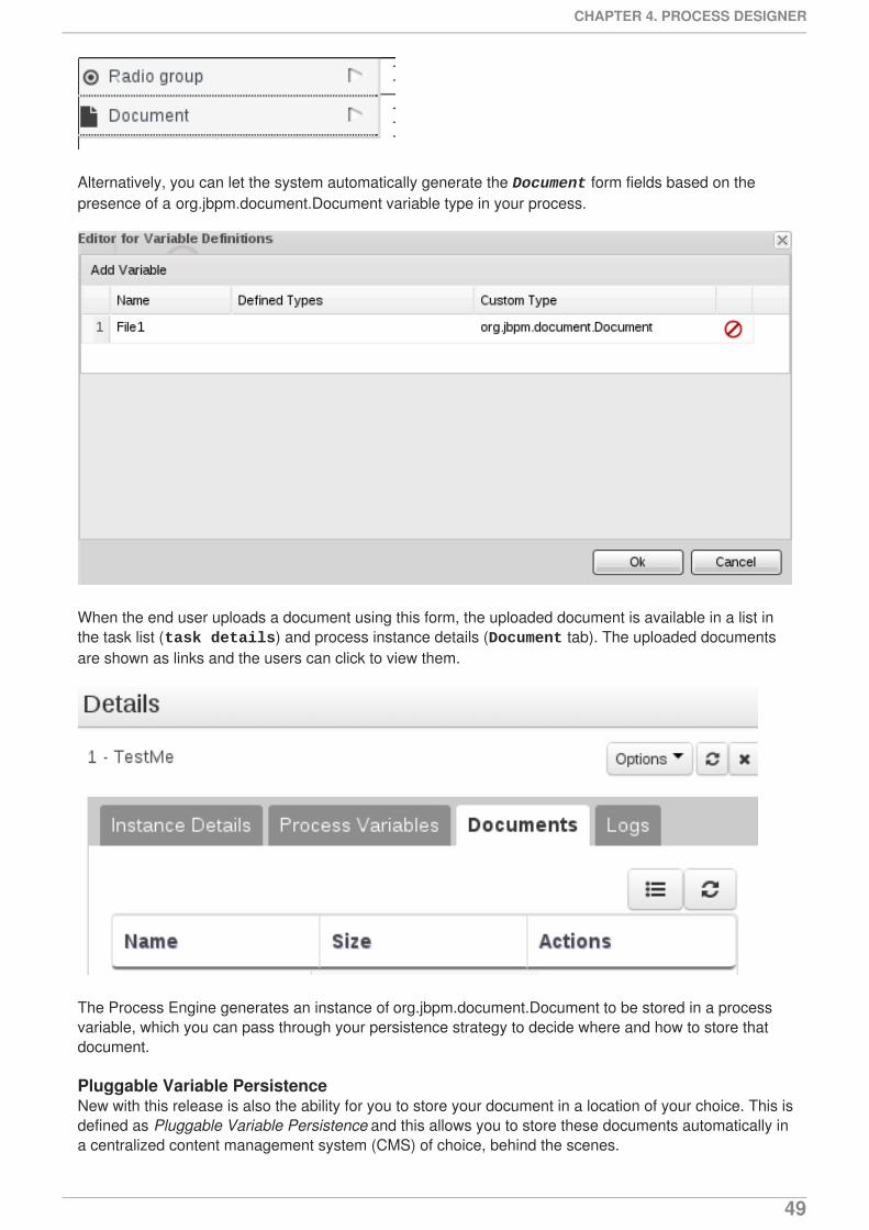
Alternatively, you can let the system automatically generate the Document form fields based on thepresence of a org.jbpm.document.Document variable type in your process.
When the end user uploads a document using this form, the uploaded document is available in a list inthe task list (task details) and process instance details (Document tab). The uploaded documentsare shown as links and the users can click to view them.
The Process Engine generates an instance of org.jbpm.document.Document to be stored in a processvariable, which you can pass through your persistence strategy to decide where and how to store thatdocument.
Pluggable Variable PersistenceNew with this release is also the ability for you to store your document in a location of your choice. This isdefined as Pluggable Variable Persistence and this allows you to store these documents automatically ina centralized content management system (CMS) of choice, behind the scenes.
CHAPTER 4. PROCESS DESIGNER
49
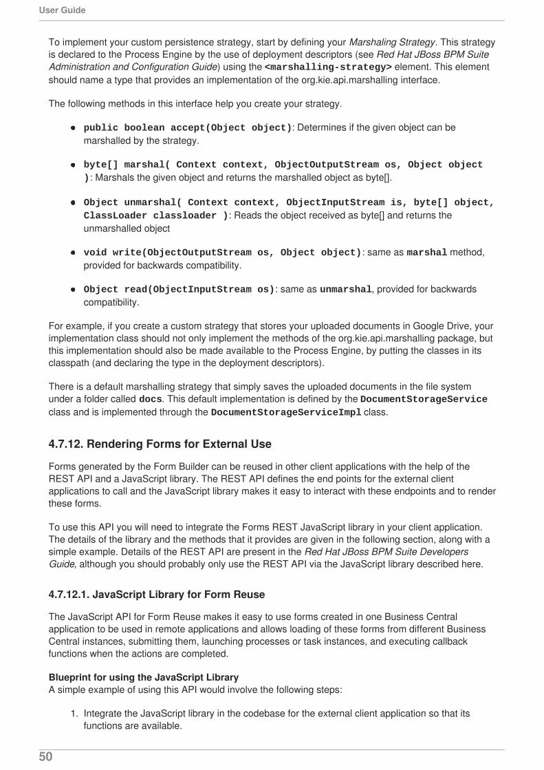
To implement your custom persistence strategy, start by defining your Marshaling Strategy. This strategyis declared to the Process Engine by the use of deployment descriptors (see Red Hat JBoss BPM SuiteAdministration and Configuration Guide) using the <marshalling-strategy> element. This elementshould name a type that provides an implementation of the org.kie.api.marshalling interface.
The following methods in this interface help you create your strategy.
public boolean accept(Object object): Determines if the given object can bemarshalled by the strategy.
byte[] marshal( Context context, ObjectOutputStream os, Object object ): Marshals the given object and returns the marshalled object as byte[].
Object unmarshal( Context context, ObjectInputStream is, byte[] object, ClassLoader classloader ): Reads the object received as byte[] and returns theunmarshalled object
void write(ObjectOutputStream os, Object object): same as marshal method,provided for backwards compatibility.
Object read(ObjectInputStream os): same as unmarshal, provided for backwardscompatibility.
For example, if you create a custom strategy that stores your uploaded documents in Google Drive, yourimplementation class should not only implement the methods of the org.kie.api.marshalling package, butthis implementation should also be made available to the Process Engine, by putting the classes in itsclasspath (and declaring the type in the deployment descriptors).
There is a default marshalling strategy that simply saves the uploaded documents in the file systemunder a folder called docs. This default implementation is defined by the DocumentStorageServiceclass and is implemented through the DocumentStorageServiceImpl class.
4.7.12. Rendering Forms for External Use
Forms generated by the Form Builder can be reused in other client applications with the help of theREST API and a JavaScript library. The REST API defines the end points for the external clientapplications to call and the JavaScript library makes it easy to interact with these endpoints and to renderthese forms.
To use this API you will need to integrate the Forms REST JavaScript library in your client application.The details of the library and the methods that it provides are given in the following section, along with asimple example. Details of the REST API are present in the Red Hat JBoss BPM Suite DevelopersGuide, although you should probably only use the REST API via the JavaScript library described here.
4.7.12.1. JavaScript Library for Form Reuse
The JavaScript API for Form Reuse makes it easy to use forms created in one Business Centralapplication to be used in remote applications and allows loading of these forms from different BusinessCentral instances, submitting them, launching processes or task instances, and executing callbackfunctions when the actions are completed.
Blueprint for using the JavaScript LibraryA simple example of using this API would involve the following steps:
1. Integrate the JavaScript library in the codebase for the external client application so that itsfunctions are available.
User Guide
50
2. Create a new instance of the jBPMFormsAPI class in your own JavaScript code. This is thestarting point for all interactions with this library.
3. Call your desired methods on this instance. For example, if you want to show a form, you woulduse the following method:
and provide the relevant details (hostUrl, deploymentId, processId and so on. A full list of themethods and parameters follows after this section).
4. Do post processing with the optional onsuccess and onerror methods.
5. Work with the form, starting processes (startProcess()), claiming tasks (claimTask())starting tasks (startTask()) or completing tasks (completeTask). Full list of availablemethods follows after this section.
6. Once you're finished with the form, clear the container that displayed it using clearContainer() method.
Full list of available methods in the JavaScript LibraryThe JavaScript library is pretty comprehensive and provides several methods to render and processforms.
1. showStartProcessForm(hostUrl, deploymentId, processId, divId, onsuccessCallback, onerrorCallback): Makes a call to the REST endpoint to obtainthe form URL. If it receives a valid response, it embeds the process start form in the stated div.You need these parameters:
hostURL: The URL of the Business Central instance that holds the deployments.
deploymentId: The deployment identifier that contains the process to run.
processId: The identifier of the process to run.
divId: The identifier of the div that has to contain the form.
onsuccessCallback (optional): A JavaScript function executed if the form is going to berendered. This function will receive the server response as a parameter.
onerrorCallback (optional): A JavaScript function executed if any error occurs and it isimpossible to render the form. This function will receive the server response as a parameter.
2. startProcess(divId, onsuccessCallback, onerrorCallback): Submits the formloaded on the stated div and starts the process. You need these parameters:
divId: The identifier of the div that contains the form.
onsuccessCallback(optional): A JavaScript function executed after the process isstarted. This function receives the server response as a parameter.
var jbpmRestAPI = new jBPMFormsAPI();
jbpmRestAPI.showStartProcessForm(hostUrl, deploymentId, processId, divId, onsuccess, onerror);
CHAPTER 4. PROCESS DESIGNER
51
onerrorCallback (optional): A JavaScript function executed if any error occurs and it isimpossible to start the process. This function receives the server response as a parameter.
3. showTaskForm(hostUrl, taskId, divId, onsuccessCallback, onerrorCallback): Makes a call to the REST endpoint to obtain the form URL. If it receivesa valid response, it embeds the task form in the stated div. You need these parameters:
hostURL: The URL of the Business Central instance that holds the deployments.
taskId: The identifier of the task to show the form.
divId: The identifier of the div that has to contain the form.
onsuccessCallback (optional): A JavaScript function executed if the form is going to berendered. This function receives the server response as a parameter.
onerrorCallback (optional): A JavaScript function executed if any error occurs and it isimpossible to render the form. This function receives the server response as a parameter.
4. claimTask(divId, onsuccessCallback, onerrorCallback): Claims the task whoseform is being rendered. You need these parameters:
divId: The identifier of the div that contains the form.
onsuccessCallback (optional): A JavaScript function executed after the task is claimed.This function receives the server response as a parameter.
onerrorCallback (optional): A JavaScript function executed if any error occurs and it isimpossible to claim the task. This function receives the server response as a parameter.
5. startTask(divId, onsuccessCallback, onerrorCallback): Starts the task whoseform is being rendered. You need these parameters:
divId: The identifier of the div that contains the form.
onsuccessCallback (optional): A JavaScript function executed after the task is claimed.This function receives the server response as a parameter.
onerrorCallback (optional): A JavaScript function executed if any error occurs and it isimpossible to claim the task. This function receives the server response as a parameter.
6. releaseTask(divId, onsuccessCallback, onerrorCallback): Releases the taskwhose form is being rendered. You need these parameters:
divId: The identifier of the div that contains the form.
onsuccessCallback (optional): A JavaScript function executed after the task is claimed.This function receives the server response as a parameter.
onerrorCallback (optional): A JavaScript function executed if any error occurs and it isimpossible to claim the task. This function receives the server response as a parameter.
7. saveTask(divId, onsuccessCallback, onerrorCallback): Submits the form andsaves the state of the task whose form is being rendered. You need these parameters:
divId: The identifier of the div that contains the form.
User Guide
52
onsuccessCallback (optional): A JavaScript function executed after the task is claimed.This function receives the server response as a parameter.
onerrorCallback (optional): A JavaScript function executed if any error occurs and it isimpossible to claim the task. This function receives the server response as a parameter.
8. completeTask(divId, onsuccessCallback, onerrorCallback): Submits the formand completes task whose form is being rendered. You need these parameters:
divId: The identifier of the div that contains the form.
onsuccessCallback (optional): A JavaScript function executed after the task is claimed.This function receives the server response as a parameter.
onerrorCallback (optional): A JavaScript function executed if any error occurs and it isimpossible to claim the task. This function receives the server response as a parameter.
9. clearContainer(divId): Cleans the div content and the related data stored on thecomponent. You need these parameters:
divId: The identifier of the div that contains the form.
4.8. VARIABLES
Variables are elements that serve for storing a particular type of data during runtime. The type of data avariable contains is defined by its data type.
Just like any context data, every variable has its scope that defines its "visibility". An element, such as aProcess, Sub-Process, or Task can only access variables in its own and parent contexts: variablesdefined in the element's child elements cannot be accessed. Therefore, when an elements requiresaccess to a variable on runtime, its own context is searched first. If the variable cannot be found directlyin the element's context, the immediate parent context is searched. The search continues to "level up"until the Process context is reached; in case of Globals, the search is performed directly on the Sessioncontainer. If the variable cannot be found, a read access request returns null and a write accessproduces an error message, and the Process continues its execution. Variables are searched for basedon their ID.
In Red Hat JBoss BPM Suite, variables can live in the following contexts:
Session context: Globals are visible to all Process instances and assets in the given Sessionand are intended to be used primarily by business rules and by constrains. The are createddynamically by the rules or constrains.
Process context: Process variables are defined as properties in the BPMN2 definition fileand are visible within the Process instance. They are initialized at Process creation anddestroyed on Process finish.
Element context: Local variables are available within their Process element, such as anActivity. They are initialized when the element context is initialized, that is, when the executionworkflow enters the node and execution of the OnEntry action finished if applicable. They aredestroyed when the element context is destroyed, that is, when the execution workflow leavesthe element.
Values of local variables can be mapped to Global or Process variables using the Assignmentmechanism (refer to Section 4.11, “Assignment”). This allows you to maintain relativeindependence of the parent Element that accommodates the local variable. Such isolation may
CHAPTER 4. PROCESS DESIGNER
53
help prevent technical exceptions.
4.8.1. Globals
A global is a variable that exists in a Knowledge Session and can be accessed and is shared by allassets in that Session. Globals belong to the particular Session of the Knowledge Base: they are used topass information to the engine.
Every global defines its ID and item subject reference: the ID serves as the variable name and must beunique within the Process definition. The item subject reference defines the data type the variable stores.
IMPORTANT
The rules are evaluated at the moment the fact is inserted. Therefore, if you are using aGlobal to constraint a fact pattern, and the global is not set, the system returns a NullPointerException.
4.8.1.1. Creating Globals
Globals are initialized when the Process with the variable definition is added to the Session or when theSession is initialized with Globals as its parameters. Their value can be changed by the ProcessActivities using the Assignment, when the global variable is associated with the local Activity context,local Activity variable, or by a direct call to the variable from a child context.
Procedure 4.4. Defining a Global in the Process Designer
To define a Process variable, do the following:
1. Open the Process in the Process Designer.
2. In the Properties panel of the BPMN Diagram expand the Extra item.
3. Click the empty value cell next to the Globals and click the arrow.
User Guide
54
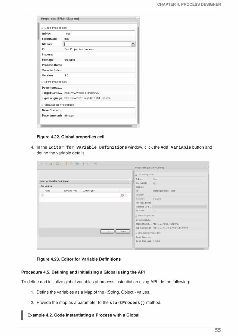
Figure 4.22. Global properties cell
4. In the Editor for Variable Definitions window, click the Add Variable button anddefine the variable details.
Figure 4.23. Editor for Variable Definitions
Procedure 4.5. Defining and Initializing a Global using the API
To define and initialize global variables at process instantiation using API, do the following:
1. Define the variables as a Map of the <String, Object> values.
2. Provide the map as a parameter to the startProcess() method.
Example 4.2. Code instantiating a Process with a Global
CHAPTER 4. PROCESS DESIGNER
55
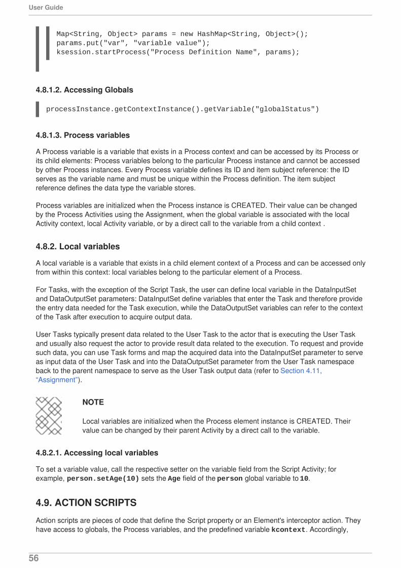
4.8.1.2. Accessing Globals
4.8.1.3. Process variables
A Process variable is a variable that exists in a Process context and can be accessed by its Process orits child elements: Process variables belong to the particular Process instance and cannot be accessedby other Process instances. Every Process variable defines its ID and item subject reference: the IDserves as the variable name and must be unique within the Process definition. The item subjectreference defines the data type the variable stores.
Process variables are initialized when the Process instance is CREATED. Their value can be changedby the Process Activities using the Assignment, when the global variable is associated with the localActivity context, local Activity variable, or by a direct call to the variable from a child context .
4.8.2. Local variables
A local variable is a variable that exists in a child element context of a Process and can be accessed onlyfrom within this context: local variables belong to the particular element of a Process.
For Tasks, with the exception of the Script Task, the user can define local variable in the DataInputSetand DataOutputSet parameters: DataInputSet define variables that enter the Task and therefore providethe entry data needed for the Task execution, while the DataOutputSet variables can refer to the contextof the Task after execution to acquire output data.
User Tasks typically present data related to the User Task to the actor that is executing the User Taskand usually also request the actor to provide result data related to the execution. To request and providesuch data, you can use Task forms and map the acquired data into the DataInputSet parameter to serveas input data of the User Task and into the DataOutputSet parameter from the User Task namespaceback to the parent namespace to serve as the User Task output data (refer to Section 4.11,“Assignment”).
NOTE
Local variables are initialized when the Process element instance is CREATED. Theirvalue can be changed by their parent Activity by a direct call to the variable.
4.8.2.1. Accessing local variables
To set a variable value, call the respective setter on the variable field from the Script Activity; forexample, person.setAge(10) sets the Age field of the person global variable to 10.
4.9. ACTION SCRIPTS
Action scripts are pieces of code that define the Script property or an Element's interceptor action. Theyhave access to globals, the Process variables, and the predefined variable kcontext. Accordingly,
Map<String, Object> params = new HashMap<String, Object>();params.put("var", "variable value");ksession.startProcess("Process Definition Name", params);
processInstance.getContextInstance().getVariable("globalStatus")
User Guide
56
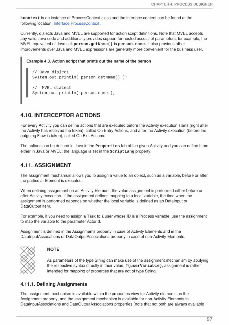
kcontext is an instance of ProcessContext class and the interface content can be found at thefollowing location: Interface ProcessContext.
Currently, dialects Java and MVEL are supported for action script definitions. Note that MVEL acceptsany valid Java code and additionally provides support for nested access of parameters, for example, theMVEL equivalent of Java call person.getName() is person.name. It also provides otherimprovements over Java and MVEL expressions are generally more convenient for the business user.
Example 4.3. Action script that prints out the name of the person
4.10. INTERCEPTOR ACTIONS
For every Activity you can define actions that are executed before the Activity execution starts (right afterthe Activity has received the token), called On Entry Actions, and after the Activity execution (before theoutgoing Flow is taken), called On Exit Actions.
The actions can be defined in Java in the Properties tab of the given Activity and you can define themeither in Java or MVEL: the language is set in the ScriptLang property.
4.11. ASSIGNMENT
The assignment mechanism allows you to assign a value to an object, such as a variable, before or afterthe particular Element is executed.
When defining assignment on an Activity Element, the value assignment is performed either before orafter Activity execution. If the assignment defines mapping to a local variable, the time when theassignment is performed depends on whether the local variable is defined as an DataInput orDataOutput item.
For example, if you need to assign a Task to a user whose ID is a Process variable, use the assignmentto map the variable to the parameter ActorId.
Assignment is defined in the Assignments property in case of Activity Elements and in theDataInputAssocations or DataOutputAssociations property in case of non-Activity Elements.
NOTE
As parameters of the type String can make use of the assignment mechanism by applyingthe respective syntax directly in their value, #{userVariable}, assignment is ratherintended for mapping of properties that are not of type String.
4.11.1. Defining Assignments
The assignment mechanism is available within the properties view for Activity elements as theAssignment property, and the assignment mechanism is available for non-Activity Elements inDataInputAssociations and DataOutputAssociations properties (note that not both are always available
// Java dialectSystem.out.println( person.getName() );
// MVEL dialectSystem.out.println( person.name );
CHAPTER 4. PROCESS DESIGNER
57
depending on the semantics of the Elements).
Data Assignments are divided into two groups:
Data Input - works only with Variables and Data Inputs.
Data Output - works only with Variables and Data Outputs.
To define an assignment, select the activity and then open up the Properties panel. Click in the Valuecolumn for the Assignments property, and then click the drop-down arrow. This will open up theAssignment Editor.
Click one of the three buttons in this editor to add a new assignment. Available objects and assignmentvalues, created separately, are available after clicking the drop-down arrow in the respective field.
1. Input Assignment: Lets you assign a Data Input to a literal value.
2. Input Mapping: Lets you map a Data Input variable to an object.
3. Output Mapping: Lets you map a Data Output variable to an object variable.
The resulting string (as shown in the figure) for the assignments will resemble: [din]DI1=65.0,[din]var1->DI2,[dout]DO1->var2
It is no longer possible to add invalid assignments as used to be case in previous versions of theAssignment Editor.
4.12. CONSTRAINTS
A Constraint is a boolean expression that is evaluated when the Element with the constraint is executed.The workflow continues depending on the result of the evaluation (true or false).
There are two types of constraints:
Code constraints are defined either in Java or MVEL. They have access to data in the workingmemory, including the Globals and Process variables.
Example 4.4. Code constraint defined in Java
return person.getAge() > 20;
User Guide
58
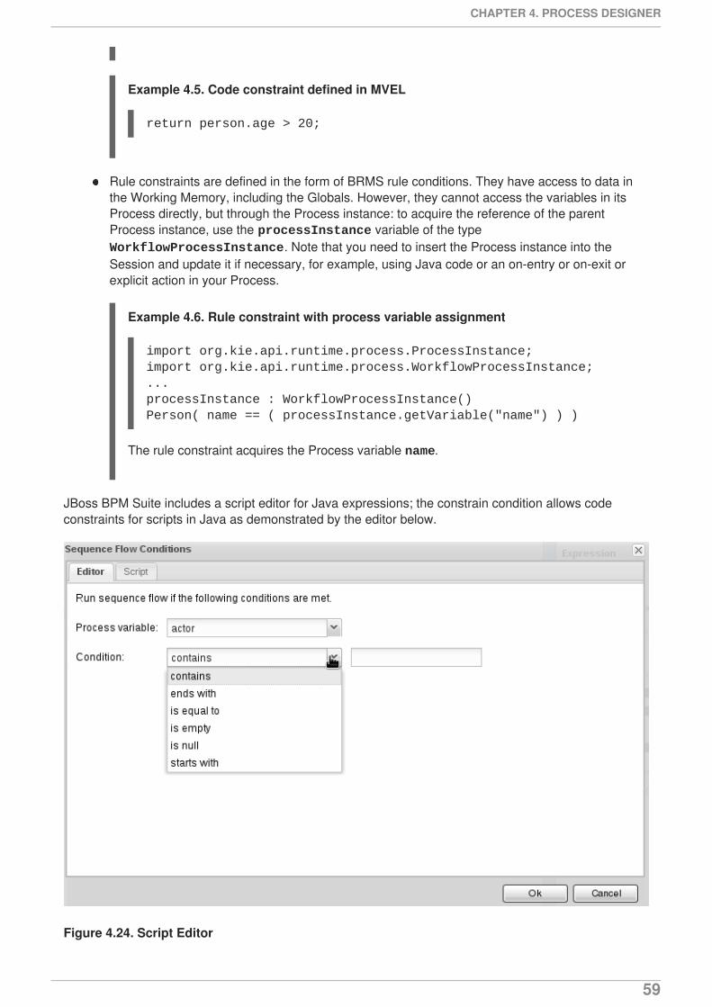
Example 4.5. Code constraint defined in MVEL
Rule constraints are defined in the form of BRMS rule conditions. They have access to data inthe Working Memory, including the Globals. However, they cannot access the variables in itsProcess directly, but through the Process instance: to acquire the reference of the parentProcess instance, use the processInstance variable of the type WorkflowProcessInstance. Note that you need to insert the Process instance into theSession and update it if necessary, for example, using Java code or an on-entry or on-exit orexplicit action in your Process.
Example 4.6. Rule constraint with process variable assignment
The rule constraint acquires the Process variable name.
JBoss BPM Suite includes a script editor for Java expressions; the constrain condition allows codeconstraints for scripts in Java as demonstrated by the editor below.
Figure 4.24. Script Editor
return person.age > 20;
import org.kie.api.runtime.process.ProcessInstance;import org.kie.api.runtime.process.WorkflowProcessInstance;...processInstance : WorkflowProcessInstance()Person( name == ( processInstance.getVariable("name") ) )
CHAPTER 4. PROCESS DESIGNER
59
When a script for Java cannot be represented by this editor, it shows an alert like the following:
4.13. DATA MODELS
Data models are models of data objects. A data object is a custom complex data type (for example, aPerson object with data fields Name, Address, and Date of Birth).
Data models are saved in data models definitions stored in your Project. Red Hat JBoss BPM Suiteprovides the Data modeler, a custom graphical editor, for defining data objects.
IMPORTANT
Every data object is implemented as a POJO and you need to import its class explicitlyinto your Process definition to allow the Process definition to see the data object.
4.13.1. Data Modeler
The Data Modeler is the built-in editor for creating data objects as part of a Project data model fromBusiness Central. Data objects are custom data types implemented as POJOs. These custom data typescan then be used in any resource (such as a Process) after importing them.
To open the editor, open the Project Authoring perspective, click New Item → Data Object on theperspective menu. If you want to edit an existing model, these files are located under Data Objects in Project Explorer.
You will be prompted to enter the name of this model object, when creating a new model, and asked toselect a location for it (in terms of the package). On successful addition, it will bring up the editor whereyou can create fields for your model object.
The Data Modeler supports roundtrips between the Editor and Source tabs, along with source codepreservation. This allows you to make changes to your model in external tools, like JBDS, and the DataModeler updates the necessary code blocks automatically.
4.13.2. Creating a data object
1. Open the Data Modeler: in the Project Authoring perspective, click New Item → Data Object onthe perspective menu. Enter the name (unique across the whole project and not just thepackage) and the location and press the Ok button.
2. Create fields of the data object:
a. In the Create new field part of the Fields panel, define the field properties:
Id: field ID unique within the data object
Label: label to be used in the Fields panel
Type: data type of the field
b. Click Create.
return true;
User Guide
60
IMPORTANT
To use a data object, make sure you import the data model into your resource. This isnecessary even if the data model lives in the same Project as your resource (BusinessProcess).
4.13.3. Annotations in Data Modeler
The Data Modeler in Business Central supports the editing of pre-defined annotations of fact modelclasses and attributes. For the fact model, the annotations supported are: TypeSafe, Role, Timestamp,Duration and Expires. For the fields within the fact model, the position annotation is supported.
If you want to add/edit custom or pre-defined annotations, you can switch to the source tab and modifythe source code directly (in JBDS or Business Central).
4.14. DOMAIN-SPECIFIC TASKS
A domain-specific Task represents a custom Task element with custom properties and handling specifictasks for the given field or company. It is used repeatedly in different business processes and typicallyaccommodates interactions with other technical system.
In Red Hat JBoss BPM Suite, domain-specific task nodes are referred to as custom work items or custom service nodes.
When creating custom work items, you define the following:
work item handler
The work item handler is a Java class that defines how to execute the custom task type. (Just like allProcess elements, Tasks are executed in the Execution Engine (more precisely in the Task Engine),which contains a work item handler class, that defines how to handle the particular work item.Therefore, to allow the Execution Engine to execute your custom work item, you need to create awork item handler class for the custom work item and register it with the Execution Engine.)
work item definition
The work item definition defines how the custom task is presented (its name, icon, parameters).
NOTE
In BPMN2, custom work items are defined either as types of <task> nodes or<serviceTask> or <sendTask> nodes.
4.14.1. Work item definition
A work item definition is a resource in a project that defines how a work item is presented (its name, icon,parameters), that is, it defines the what part (the how part is implemented as a class that implements WorkItemHandler).
Depending on the Process Designer you are using, you define a work item definition in the followingways:
Web Process Designer
CHAPTER 4. PROCESS DESIGNER
61
A work item definition is defined as an MVEL construct in a project resource (the custom work itemnode will appear on the palette; refer to Section 4.14.1.2, “Creating a work item definition”).
JBoss Developer Studio Process Designer
The BPMN2 <task> or <task>-type elements can be modified to work with WorkItemHandlerimplementations.
To do so, create a WID_NAME.wid file under the META-INF directory. (Example: $PROJECT_HOME/src/main/resources/META-INF/WID_NAME.wid). The contents of this filewill be the same as the ones that you will create as if under Business Central (Web ProcessDesigner). If there are any icons, create these icons under a folder $PROJECT_HOME/src/main/resources/, and store the icon images files in icons folder.
Once you save this file, you can use your custom service task with the JBDS Process Designer. Youcan find your task in the category which is defined in WID_NAME.wid file.
A work item has the following properties:
name unique in the given work item set
description with arbitrary text
version number
parameters with a set of work item parameters used as properties
displayName used in the palette
icon with the path to the icon file for the Task element
category the node is added to in the palette (if the defined category does not exit, a newcategory is created)
defaultHandler with the class that implements the WorkItemHandler class and is used toexecute the work item
dependencies the defaultHandler requires for its execution
IMPORTANT
Work item definition contains a collection of work item definitions. Therefore make sure touse square brackets correctly.
Also make sure you import any used classes and that you validate the definition oncefinished.
Example 4.7. Calendar work item definition
import org.drools.core.process.core.datatype.impl.type.StringDataType;
[ [ "name" : "Google Calendar", "description" : "Create a meeting in Google Calendar",
User Guide
62
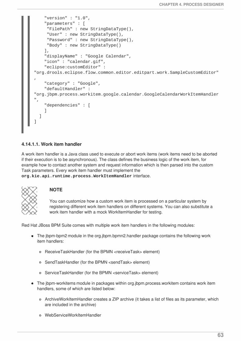
4.14.1.1. Work item handler
A work item handler is a Java class used to execute or abort work items (work items need to be abortedif their execution is to be asynchronous). The class defines the business logic of the work item, forexample how to contact another system and request information which is then parsed into the customTask parameters. Every work item handler must implement the org.kie.api.runtime.process.WorkItemHandler interface.
NOTE
You can customize how a custom work item is processed on a particular system byregistering different work item handlers on different systems. You can also substitute awork item handler with a mock WorkItemHandler for testing.
Red Hat JBoss BPM Suite comes with multiple work item handlers in the following modules:
The jbpm-bpm2 module in the org.jbpm.bpmn2.handler package contains the following workitem handlers:
ReceiveTaskHandler (for the BPMN <receiveTask> element)
SendTaskHandler (for the BPMN <sendTask> element)
ServiceTaskHandler (for the BPMN <serviceTask> element)
The jbpm-workitems module in packages within org.jbpm.process.workitem contains work itemhandlers, some of which are listed below:
ArchiveWorkItemHandler creates a ZIP archive (it takes a list of files as its parameter, whichare included in the archive)
WebServiceWorkItemHandler
"version" : "1.0", "parameters" : [ "FilePath" : new StringDataType(), "User" : new StringDataType(), "Password" : new StringDataType(), "Body" : new StringDataType() ], "displayName" : "Google Calendar", "icon" : "calendar.gif", "eclipse:customEditor" : "org.drools.eclipse.flow.common.editor.editpart.work.SampleCustomEditor", "category" : "Google", "defaultHandler" : "org.jbpm.process.workitem.google.calendar.GoogleCalendarWorkItemHandler", "dependencies" : [ ] ]]
CHAPTER 4. PROCESS DESIGNER
63
TransformWorkItemHandler
RSSWorkItemHandler
RESTWorkItemHandler
JavaInvocationWorkItemHandler
JabberWorkItemHandler
JavaHandlerWorkItemHandler
FTPUploadWorkItemHandler
ExecWorkItemHandler
EmailWorkItemHandler
The work item handlers must define the executeWorkItem() and abortWorkItem() methods asdefined by the WorkItemHandler interface. These are called during runtime on work item execution.
When a work item is executed, the following is performed:
1. Information about the Task are extracted from the WorkItem instance.
2. The work item business logic is performed.
3. The Process instance is informed that the work item execution finished (completed or aborted)using the respective method of the WorkItemManager:
for completing execution:
for aborting execution:
If a work item cannot be completed immediately and it is required that the Process execution continueswhile the work item completes the execution, the Process execution can continue asynchronously andthe work item manager can be notified about the work item completion later.
To abort the work item, use the WorkItemHandler.abortWorkItem() before it is completedSection 5.1.4.1, “Asynchronous execution”.
4.14.1.2. Creating a work item definition
To create and define a work item definition in Web Process Designer, do the following:
1. In the Project Explorer panel (the Project Authoring perspective), select your project.
import org.kie.api.runtime.process.WorkItemManager;...WorkItemManager.completeWorkItem(long workItemId, Map<String, Object> results)
import org.kie.api.runtime.process.WorkItemManager;...WorkItemManager.abortWorkItem(long workItemId, Map<String, Object> results)
User Guide
64
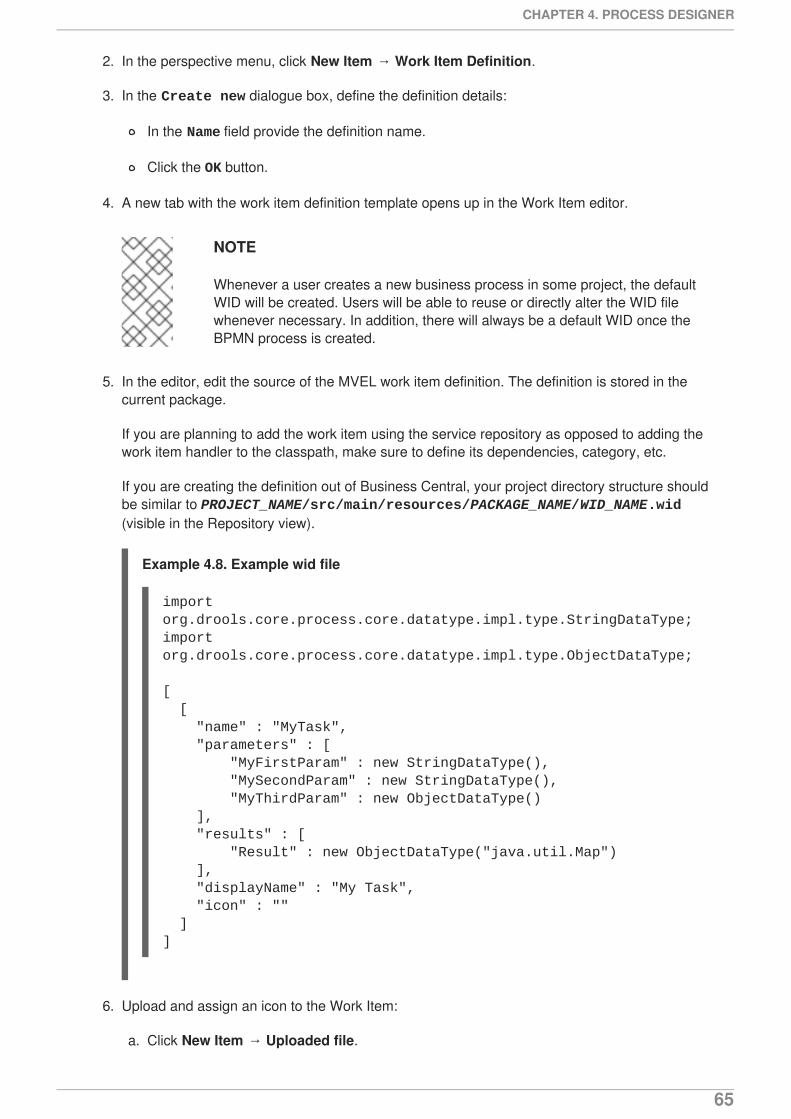
2. In the perspective menu, click New Item → Work Item Definition.
3. In the Create new dialogue box, define the definition details:
In the Name field provide the definition name.
Click the OK button.
4. A new tab with the work item definition template opens up in the Work Item editor.
NOTE
Whenever a user creates a new business process in some project, the defaultWID will be created. Users will be able to reuse or directly alter the WID filewhenever necessary. In addition, there will always be a default WID once theBPMN process is created.
5. In the editor, edit the source of the MVEL work item definition. The definition is stored in thecurrent package.
If you are planning to add the work item using the service repository as opposed to adding thework item handler to the classpath, make sure to define its dependencies, category, etc.
If you are creating the definition out of Business Central, your project directory structure shouldbe similar to PROJECT_NAME/src/main/resources/PACKAGE_NAME/WID_NAME.wid(visible in the Repository view).
Example 4.8. Example wid file
6. Upload and assign an icon to the Work Item:
a. Click New Item → Uploaded file.
import org.drools.core.process.core.datatype.impl.type.StringDataType;import org.drools.core.process.core.datatype.impl.type.ObjectDataType;
[ [ "name" : "MyTask", "parameters" : [ "MyFirstParam" : new StringDataType(), "MySecondParam" : new StringDataType(), "MyThirdParam" : new ObjectDataType() ], "results" : [ "Result" : new ObjectDataType("java.util.Map") ], "displayName" : "My Task", "icon" : "" ]]
CHAPTER 4. PROCESS DESIGNER
65
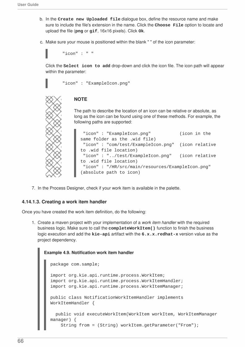
b. In the Create new Uploaded file dialogue box, define the resource name and makesure to include the file's extension in the name. Click the Choose File option to locate andupload the file (png or gif, 16x16 pixels). Click Ok.
c. Make sure your mouse is positioned within the blank " " of the icon parameter:
Click the Select icon to add drop-down and click the icon file. The icon path will appearwithin the parameter:
NOTE
The path to describe the location of an icon can be relative or absolute, aslong as the icon can be found using one of these methods. For example, thefollowing paths are supported:
7. In the Process Designer, check if your work item is available in the palette.
4.14.1.3. Creating a work item handler
Once you have created the work item definition, do the following:
1. Create a maven project with your implementation of a work item handler with the requiredbusiness logic. Make sure to call the completeWorkItem() function to finish the businesslogic execution and add the kie-api artifact with the 6.x.x.redhat-x version value as theproject dependency.
Example 4.9. Notification work item handler
"icon" : " "
"icon" : "ExampleIcon.png"
"icon" : "ExampleIcon.png" (icon in the same folder as the .wid file) "icon" : "com/test/ExampleIcon.png" (icon relative to .wid file location) "icon" : "../test/ExampleIcon.png" (icon relative to .wid file location) "icon" : "/HR/src/main/resources/ExampleIcon.png" (absolute path to icon)
package com.sample;
import org.kie.api.runtime.process.WorkItem;import org.kie.api.runtime.process.WorkItemHandler;import org.kie.api.runtime.process.WorkItemManager;
public class NotificationWorkItemHandler implements WorkItemHandler {
public void executeWorkItem(WorkItem workItem, WorkItemManager manager) { String from = (String) workItem.getParameter("From");
User Guide
66
IMPORTANT
If the WorkItemManager is not notified about the work item completion, theprocess engine is never notified that your work item node has completed.
2. Register the work item handler in the DEPLOY_DIR/business-central.war/WEB-INF/classes/META-INF/CustomWorkItemHandlers.conf file.
The CustomWorkItemHandlers.conf file contains information like the following:
Notice the "Rest" value in the previous file. This indicates the WorkItemHandler is capable ofinteracting with REST services. It supports both secured/authenticated and open/notauthenticated services.
This REST value is defined in the project's WID file in the following manner:
String to = (String) workItem.getParameter("To"); String message = (String) workItem.getParameter("Message"); String priority = (String) workItem.getParameter("Priority");
/* Send email. The ServiceRegistry class is an example class implementing the task business logic. */ EmailService service = ServiceRegistry.getInstance().getEmailService(); service.sendEmail(from, to, "Notification", message);
/* Notify manager that work item has been completed. The completeWorkItem() call completes the work item execution.*/ manager.completeWorkItem(workItem.getId(), null); }
public void abortWorkItem(WorkItem workItem, WorkItemManager manager) { // Do nothing, notifications cannot be aborted }
}
[ "Log": new org.jbpm.process.instance.impl.demo.SystemOutWorkItemHandler(), "WebService": new org.jbpm.process.workitem.webservice.WebServiceWorkItemHandler(ksession), "Rest": new org.jbpm.process.workitem.rest.RESTWorkItemHandler()]
[
CHAPTER 4. PROCESS DESIGNER
67
The configuration options displayed about must be given via the work item parameter. Theauthentication information can be given on handler initialization, but it can be overridden via thework item parameter.
3. Compile the project. The resulting JAR file should be placed in (DEPLOY_DIR/business-central.war/WEB-INF/lib/).
4. Restart the server.
Registering via kmodule.xmlAn alternative to registering work item handlers in CustomWorkItemHandlers.conf is to configurethem with kmodule.xml. This is beneficial in that it avoids a complete server restart.
1. Register the work item handler in the Administration menu path PROJECT_NAME/src/main/resources/META-INF/kmodule.xml
2. Make sure the work item handler is given as a MVEL expression; for example, new org.jbpm.wih.CustomHandler() or FQCN expression: org.jbpm.wih.CustomHandler.
3. Compile the project. Upload the work item handler JAR into Business Central via the ArtifactRepository. Then add it as a dependency for the project where the user wants to use thishandler.
"name" : "Rest", "parameters" : [ //Url - Mandatory resource location to be invoked. "Url" : new StringDataType(), //Method - Defaults to GET and is the HTTP method that will be executed. "Method" : new StringDataType(), //ConnectionTimeout - Defaults to 60 seconds for the connection timeout. "ConnectTimeout" : new StringDataType(), //ReadTimeout - Defaults to 60 seconds for the read timeout. "ReadTimeout" : new StringDataType(), //Username - The username for authentication that overrides the one given on handler initialization. "Username" : new StringDataType(), //Password - The password for authentication that overrides the one given on handler initialization. "Password" : new StringDataType() ], "results" : [ "Result" : new ObjectDataType(), ], "displayName" : "REST", "icon" : "defaultservicenodeicon.png"]
User Guide
68
4.14.1.4. Registering a Work Item handler
When executing processes in Business Central, WorkItemHandlers are registered in the ksessionautomatically. However, in order for them to be used in embedded mode, the WorkItemManagerregisters WorkItemHandler instances. Likewise, in the example below, the NotificationWorkItemHandler needs to be registered in order for it to be used with a processcontaining a Notification work item:
1. Register the work item handler like the following:
2. Look at the BPMN2 syntax for the process. The previous registration example would appear asfollows:
NOTE
Different work item handlers could be used depending on the context. For example,during testing or simulation, it might not be necessary to actually execute the work items.
4.14.2. Service repository
The service repository feature allows you to import an already existing work item from a repositorydirectly into your project. It allows multiple users to reuse generic work items , such as work itemsallowing integration with Twitter, performing file system operations, etc. Imported work items are
/* Create the drools name of the <task> and the custom work item handler instance */KieSession kieSession = kieBase.newKieSession();ksession.getWorkItemManager().registerWorkItemHandler( "Notification", new NotificationWorkItemHandler());
<?xml version="1.0" encoding="UTF-8"?> <definitions id="Definition" xmlns="http://www.omg.org/spec/BPMN/20100524/MODEL" xs:schemaLocation="http://www.omg.org/spec/BPMN/20100524/MODEL BPMN20.xsd"... xmlns:tns="http://www.jboss.org/drools">
...
<process isExecutable="true" id="myCustomProcess" name="Domain-Specific Process" >
...<!-- The tns:taskName attribute in the <task> node is necessary for the WorkItemManager to be able to see which WorkItemHandler instance should be used with which task or work item. --> <task id="_5" name="Notification Task" tns:taskName="Notification" >
...
CHAPTER 4. PROCESS DESIGNER
69
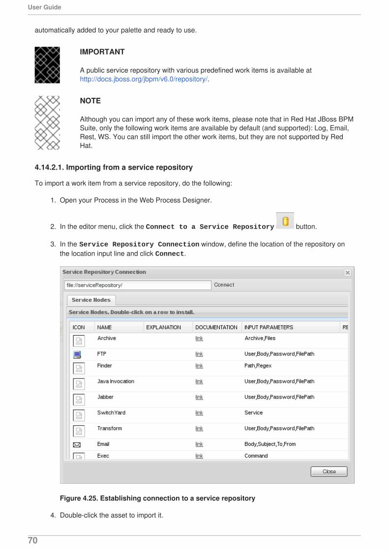
automatically added to your palette and ready to use.
IMPORTANT
A public service repository with various predefined work items is available athttp://docs.jboss.org/jbpm/v6.0/repository/.
NOTE
Although you can import any of these work items, please note that in Red Hat JBoss BPMSuite, only the following work items are available by default (and supported): Log, Email,Rest, WS. You can still import the other work items, but they are not supported by RedHat.
4.14.2.1. Importing from a service repository
To import a work item from a service repository, do the following:
1. Open your Process in the Web Process Designer.
2. In the editor menu, click the Connect to a Service Repository button.
3. In the Service Repository Connection window, define the location of the repository onthe location input line and click Connect.
Figure 4.25. Establishing connection to a service repository
4. Double-click the asset to import it.
User Guide
70
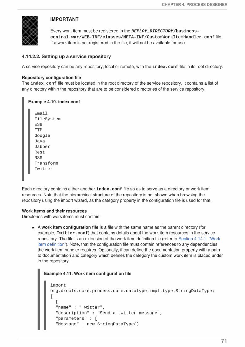
IMPORTANT
Every work item must be registered in the DEPLOY_DIRECTORY/business-central.war/WEB-INF/classes/META-INF/CustomWorkItemHandler.conf file.If a work item is not registered in the file, it will not be available for use.
4.14.2.2. Setting up a service repository
A service repository can be any repository, local or remote, with the index.conf file in its root directory.
Repository configuration fileThe index.conf file must be located in the root directory of the service repository. It contains a list ofany directory within the repository that are to be considered directories of the service repository.
Example 4.10. index.conf
Each directory contains either another index.conf file so as to serve as a directory or work itemresources. Note that the hierarchical structure of the repository is not shown when browsing therepository using the import wizard, as the category property in the configuration file is used for that.
Work items and their resourcesDirectories with work items must contain:
A work item configuration file is a file with the same name as the parent directory (forexample, Twitter.conf) that contains details about the work item resources in the servicerepository. The file is an extension of the work item definition file (refer to Section 4.14.1, “Workitem definition”). Note, that the configuration file must contain references to any dependenciesthe work item handler requires. Optionally, it can define the documentation property with a pathto documentation and category which defines the category the custom work item is placed underin the repository.
Example 4.11. Work item configuration file
EmailFileSystemESBFTPGoogleJavaJabberRestRSSTransformTwitter
import org.drools.core.process.core.datatype.impl.type.StringDataType;[ [ "name" : "Twitter", "description" : "Send a twitter message", "parameters" : [ "Message" : new StringDataType()
CHAPTER 4. PROCESS DESIGNER
71
All resources referenced in the work item configuration file: icon, documentation, anddependencies.
4.14.3. User Task calls
The User Task service exposes a Java API for managing the life cycle of its User Tasks via the TaskClient class. The API is intended for developers to allow direct managing of the lifecycle of UserTasks. End users are advised to use the Business Central web application for User Task management.
To manage user tasks via a public API use the methods of the org.kie.api.task.TaskService class. Themethods of this interface take the following arguments:
taskId: ID of the target Task instance usually extracted from the currently selected User Taskin the user task list in the user interface
userId: ID of the user that is executing the action called by the method; usually the ID of theuser that is logged in
The following is a subset of methods provided by the org.kie.api.task.TaskService class:
Example 4.12. Starting and completing a simple user task
], "displayName" : "Twitter", "eclipse:customEditor" : "org.drools.eclipse.flow.common.editor.editpart.work.SampleCustomEditor", "icon" : "twitter.gif", "category" : "Communication", "defaultHandler" : "org.jbpm.process.workitem.twitter.TwitterHandler", "documentation" : "index.html", //Every work item definition should specify dependencies even if it doesn't have one. "dependencies" : [] [ "file:./lib/jbpm-twitter.jar", "file:./lib/twitter4j-core-2.2.2.jar" ] ]]
void start(long taskId, String userId);void stop(long taskId, String userId);void release(long taskId, String userId);void suspend(long taskId, String userId);void resume(long taskId, String userId);void skip(long taskId, String userId);void delegate(long taskId, String userId, String targetUserId);void complete(long taskId, String userId, Map<String, Object> results);
import org.kie.api.runtime.KieSession;import org.kie.api.runtime.manager.RuntimeEngine;import org.kie.api.runtime.manager.RuntimeManager;
User Guide
72
4.14.4. Actor assignment calls
User Tasks must define either the ActorID or the GroupID parameter, which define the users who canor should execute the User Tasks. It is in the Task List of these users the Task appears.
If the User Task element defines exactly one user, the User Task appears only in the Task List of thatparticular user. If a User Task is assigned to more than one user, that is, to multiple actors or to a group,it appears in the Task List of all the users and any of the users can claim and execute the User Task.
End users define these properties in the Process Designer. However, the provided actor and group IDsneeds to be registered with the User Task service before they can be used by User Tasks.
You can manage actors dynamically on the TaskService.
Example 4.13. Adding user Kris and group Developers on taskSession
Also, you can specify the groups a user is a member of, such as, the default admin roles as well as yourcustom roles.
Example 4.14. Requesting the list of tasks the user is a potential owner of
import org.kie.api.runtime.process.ProcessInstance;import org.kie.api.task.TaskService;import org.kie.api.task.model.TaskSummary;
.... KieSession ksession = runtimeEngine.getKieSession();TaskService taskService = runtimeEngine.getTaskService();ProcessInstance processInstance = ksession.startProcess("com.sample.bpmn.hello");
// John is assigned a task and he completes itList<TaskSummary> list = taskService.getTasksAssignedAsPotentialOwner("john", "en-UK");TaskSummary task = list.get(0);
logger.info("John is executing task {}", task.getName());
taskService.start(task.getId(), "john");taskService.complete(task.getId(), "john", null);
...
EntityManagerFactory emf = Persistence.createEntityManagerFactory("org.jbpm.task");TaskService taskService = new TaskService(emf, SystemEventListenerFactory.getSystemEventListener());TaskServiceSession taskSession = taskService.createSession();
// registering new user and group:taskSession.addUser(new User("Kris"));taskSession.addGroup(new Group("Developers"));
CHAPTER 4. PROCESS DESIGNER
73
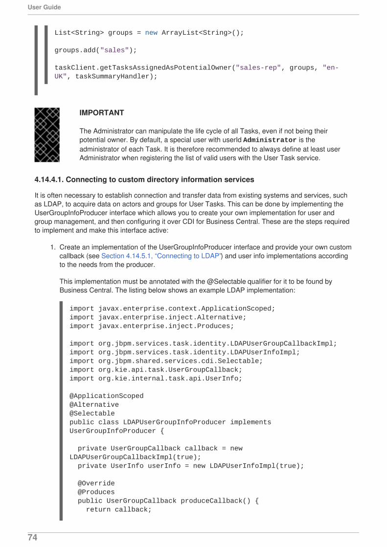
IMPORTANT
The Administrator can manipulate the life cycle of all Tasks, even if not being theirpotential owner. By default, a special user with userId Administrator is theadministrator of each Task. It is therefore recommended to always define at least userAdministrator when registering the list of valid users with the User Task service.
4.14.4.1. Connecting to custom directory information services
It is often necessary to establish connection and transfer data from existing systems and services, suchas LDAP, to acquire data on actors and groups for User Tasks. This can be done by implementing theUserGroupInfoProducer interface which allows you to create your own implementation for user andgroup management, and then configuring it over CDI for Business Central. These are the steps requiredto implement and make this interface active:
1. Create an implementation of the UserGroupInfoProducer interface and provide your own customcallback (see Section 4.14.5.1, “Connecting to LDAP”) and user info implementations accordingto the needs from the producer.
This implementation must be annotated with the @Selectable qualifier for it to be found byBusiness Central. The listing below shows an example LDAP implementation:
List<String> groups = new ArrayList<String>();
groups.add("sales");
taskClient.getTasksAssignedAsPotentialOwner("sales-rep", groups, "en-UK", taskSummaryHandler);
import javax.enterprise.context.ApplicationScoped;import javax.enterprise.inject.Alternative;import javax.enterprise.inject.Produces;
import org.jbpm.services.task.identity.LDAPUserGroupCallbackImpl;import org.jbpm.services.task.identity.LDAPUserInfoImpl;import org.jbpm.shared.services.cdi.Selectable;import org.kie.api.task.UserGroupCallback;import org.kie.internal.task.api.UserInfo;
@ApplicationScoped@Alternative@Selectablepublic class LDAPUserGroupInfoProducer implements UserGroupInfoProducer {
private UserGroupCallback callback = new LDAPUserGroupCallbackImpl(true); private UserInfo userInfo = new LDAPUserInfoImpl(true); @Override @Produces public UserGroupCallback produceCallback() { return callback;
User Guide
74
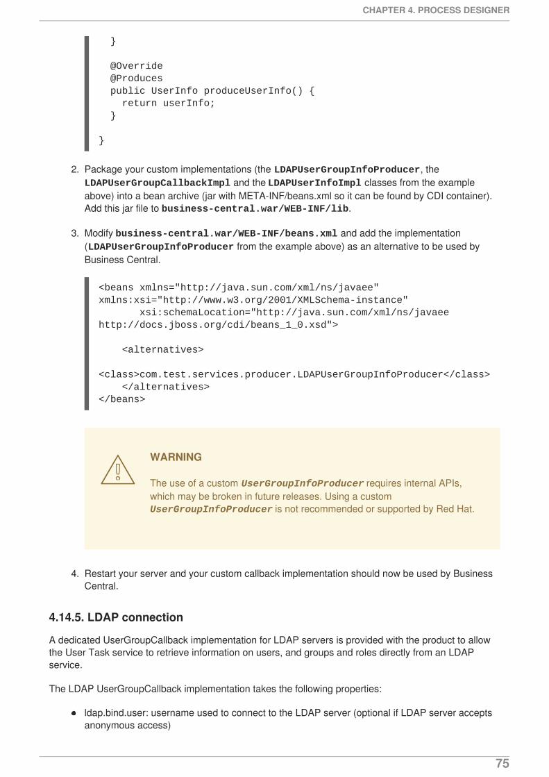
2. Package your custom implementations (the LDAPUserGroupInfoProducer, the LDAPUserGroupCallbackImpl and the LDAPUserInfoImpl classes from the exampleabove) into a bean archive (jar with META-INF/beans.xml so it can be found by CDI container).Add this jar file to business-central.war/WEB-INF/lib.
3. Modify business-central.war/WEB-INF/beans.xml and add the implementation(LDAPUserGroupInfoProducer from the example above) as an alternative to be used byBusiness Central.
WARNING
The use of a custom UserGroupInfoProducer requires internal APIs,which may be broken in future releases. Using a custom UserGroupInfoProducer is not recommended or supported by Red Hat.
4. Restart your server and your custom callback implementation should now be used by BusinessCentral.
4.14.5. LDAP connection
A dedicated UserGroupCallback implementation for LDAP servers is provided with the product to allowthe User Task service to retrieve information on users, and groups and roles directly from an LDAPservice.
The LDAP UserGroupCallback implementation takes the following properties:
ldap.bind.user: username used to connect to the LDAP server (optional if LDAP server acceptsanonymous access)
}
@Override @Produces public UserInfo produceUserInfo() { return userInfo; }
}
<beans xmlns="http://java.sun.com/xml/ns/javaee" xmlns:xsi="http://www.w3.org/2001/XMLSchema-instance" xsi:schemaLocation="http://java.sun.com/xml/ns/javaee http://docs.jboss.org/cdi/beans_1_0.xsd">
<alternatives> <class>com.test.services.producer.LDAPUserGroupInfoProducer</class> </alternatives></beans>
CHAPTER 4. PROCESS DESIGNER
75

ldap.bind.pwd: password used to connect to the LDAP server (optional if LDAP server acceptsanonymous access)
ldap.user.ctx: context in LDAP with user information (mandatory)
ldap.role.ctx: context in LDAP with group and role information (mandatory)
ldap.user.roles.ctx: context in LDAP with user group and role membership information (optional;if not specified, ldap.role.ctx is used)
ldap.user.filter: filter used to search for user information; usually contains substitution keys {0},which are replaced with parameters (mandatory)
ldap.role.filter: filter used to search for group and role information, usually contains substitutionkeys {0}, which are replaced with parameters (mandatory)
ldap.user.roles.filter: filter used to search for user group and role membership information,usually contains substitution keys {0}, which are replaced with parameters (mandatory)
ldap.user.attr.id: attribute name of the user ID in LDAP (optional; if not specified, uid is used)
ldap.roles.attr.id: attribute name of the group and role ID in LDAP (optional; if not specified cn isused)
ldap.user.id.dn: user ID in a DN, instructs the callback to query for user DN before searching forroles (optional, by default false)
java.naming.factory.initial: initial conntext factory class name (by default com.sun.jndi.ldap.LdapCtxFactory)
java.naming.security.authentication: authentication type (possible values are none, simple, strong; by default simple)
java.naming.security.protocol: security protocol to be used; for instance ssl
java.naming.provider.url: LDAP url (by default ldap://localhost:389; if the protocol is set tossl then ldap://localhost:636)
4.14.5.1. Connecting to LDAP
To be able to use the LDAP UserGroupCallback implementation configure the respective LDAPproperties (refer to Section 4.14.5, “LDAP connection”) in one of the following ways:
programatically: build a Properties object with the respective LDAPUserGroupCallbackImplproperties and create LDAPUserGroupCallbackImpl with the Properties object as itsparameter.
Example 4.15.
import org.kie.api.PropertiesConfiguration;import org.kie.api.task.UserGroupCallback;...Properties properties = new Properties();properties.setProperty(LDAPUserGroupCallbackImpl.USER_CTX, "ou=People,dc=my-domain,dc=com");properties.setProperty(LDAPUserGroupCallbackImpl.ROLE_CTX,
User Guide
76
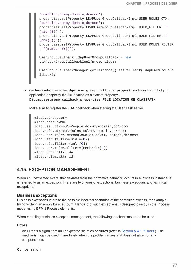
declaratively: create the jbpm.usergroup.callback.properties file in the root of yourapplication or specify the file location as a system property: -Djbpm.usergroup.callback.properties=FILE_LOCATION_ON_CLASSPATH
Make sure to register the LDAP callback when starting the User Task server.
4.15. EXCEPTION MANAGEMENT
When an unexpected event, that deviates from the normative behavior, occurs in a Process instance, itis referred to as an exception. There are two types of exceptions: business exceptions and technicalexceptions.
Business exceptionsBusiness exceptions relate to the possible incorrect scenarios of the particular Process, for example,trying to debit an empty bank account. Handling of such exceptions is designed directly in the Processmodel using BPMN Process elements.
When modeling business exception management, the following mechanisms are to be used:
Errors
An Error is a signal that an unexpected situation occurred (refer to Section A.4.1, “Errors”). Themechanism can be used immediately when the problem arises and does not allow for anycompensation.
Compensation
"ou=Roles,dc=my-domain,dc=com");properties.setProperty(LDAPUserGroupCallbackImpl.USER_ROLES_CTX, "ou=Roles,dc=my-domain,dc=com");properties.setProperty(LDAPUserGroupCallbackImpl.USER_FILTER, "(uid={0})");properties.setProperty(LDAPUserGroupCallbackImpl.ROLE_FILTER, "(cn={0})");properties.setProperty(LDAPUserGroupCallbackImpl.USER_ROLES_FILTER, "(member={0})");
UserGroupCallback ldapUserGroupCallback = new LDAPUserGroupCallbackImpl(properties);
UserGroupCallbackManager.getInstance().setCallback(ldapUserGroupCallback);
#ldap.bind.user=#ldap.bind.pwd=ldap.user.ctx=ou\=People,dc\=my-domain,dc\=comldap.role.ctx=ou\=Roles,dc\=my-domain,dc\=comldap.user.roles.ctx=ou\=Roles,dc\=my-domain,dc\=comldap.user.filter=(uid\={0})ldap.role.filter=(cn\={0})ldap.user.roles.filter=(member\={0})#ldap.user.attr.id=#ldap.roles.attr.id=
CHAPTER 4. PROCESS DESIGNER
77

Compensation is equivalent to the Error mechanism; however, it can be used only on Sub-Processeswhen it is required that the execution flow continues after the compensation using the "regular"outgoing Flow (execution continues after the compensation as if no compensation occurred).
Canceling
Canceling is equivalent to the Error mechanism; however, it can be used only on Sub-Processes andit is required that the Sub-Process takes the flow leaving the respective Cancel Intermediate Event sothat the "normal" execution flow is never taken as opposed to compensation.
Technical exceptionsTechnical exceptions happen when a technical component of a business process acts in an unexpectedway. When using Java-based systems, this often results in a Java Exception being thrown by thesystem. Technical components used in a Process fail in a way that can not be described using BPMN(for further information, refer to Section 5.1.5, “Technical exceptions”).
User Guide
78
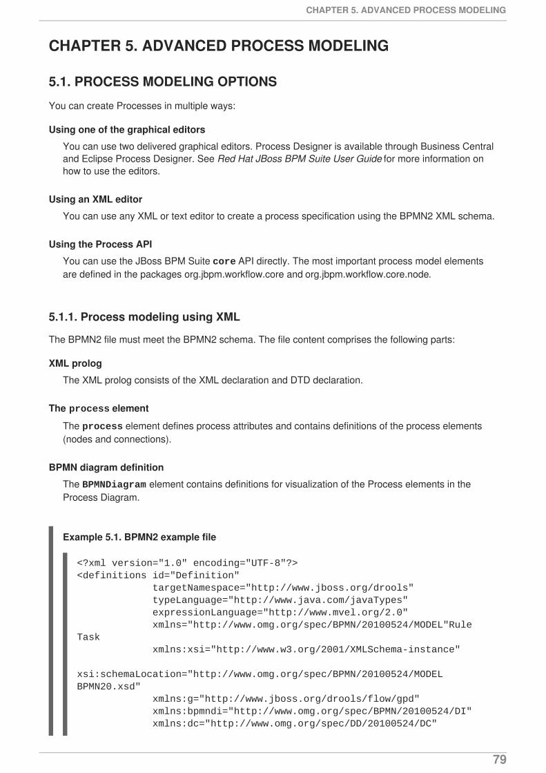
CHAPTER 5. ADVANCED PROCESS MODELING
5.1. PROCESS MODELING OPTIONS
You can create Processes in multiple ways:
Using one of the graphical editors
You can use two delivered graphical editors. Process Designer is available through Business Centraland Eclipse Process Designer. See Red Hat JBoss BPM Suite User Guide for more information onhow to use the editors.
Using an XML editor
You can use any XML or text editor to create a process specification using the BPMN2 XML schema.
Using the Process API
You can use the JBoss BPM Suite core API directly. The most important process model elementsare defined in the packages org.jbpm.workflow.core and org.jbpm.workflow.core.node.
5.1.1. Process modeling using XML
The BPMN2 file must meet the BPMN2 schema. The file content comprises the following parts:
XML prolog
The XML prolog consists of the XML declaration and DTD declaration.
The process element
The process element defines process attributes and contains definitions of the process elements(nodes and connections).
BPMN diagram definition
The BPMNDiagram element contains definitions for visualization of the Process elements in theProcess Diagram.
Example 5.1. BPMN2 example file
<?xml version="1.0" encoding="UTF-8"?><definitions id="Definition" targetNamespace="http://www.jboss.org/drools" typeLanguage="http://www.java.com/javaTypes" expressionLanguage="http://www.mvel.org/2.0" xmlns="http://www.omg.org/spec/BPMN/20100524/MODEL"Rule Task xmlns:xsi="http://www.w3.org/2001/XMLSchema-instance" xsi:schemaLocation="http://www.omg.org/spec/BPMN/20100524/MODEL BPMN20.xsd" xmlns:g="http://www.jboss.org/drools/flow/gpd" xmlns:bpmndi="http://www.omg.org/spec/BPMN/20100524/DI" xmlns:dc="http://www.omg.org/spec/DD/20100524/DC"
CHAPTER 5. ADVANCED PROCESS MODELING
79
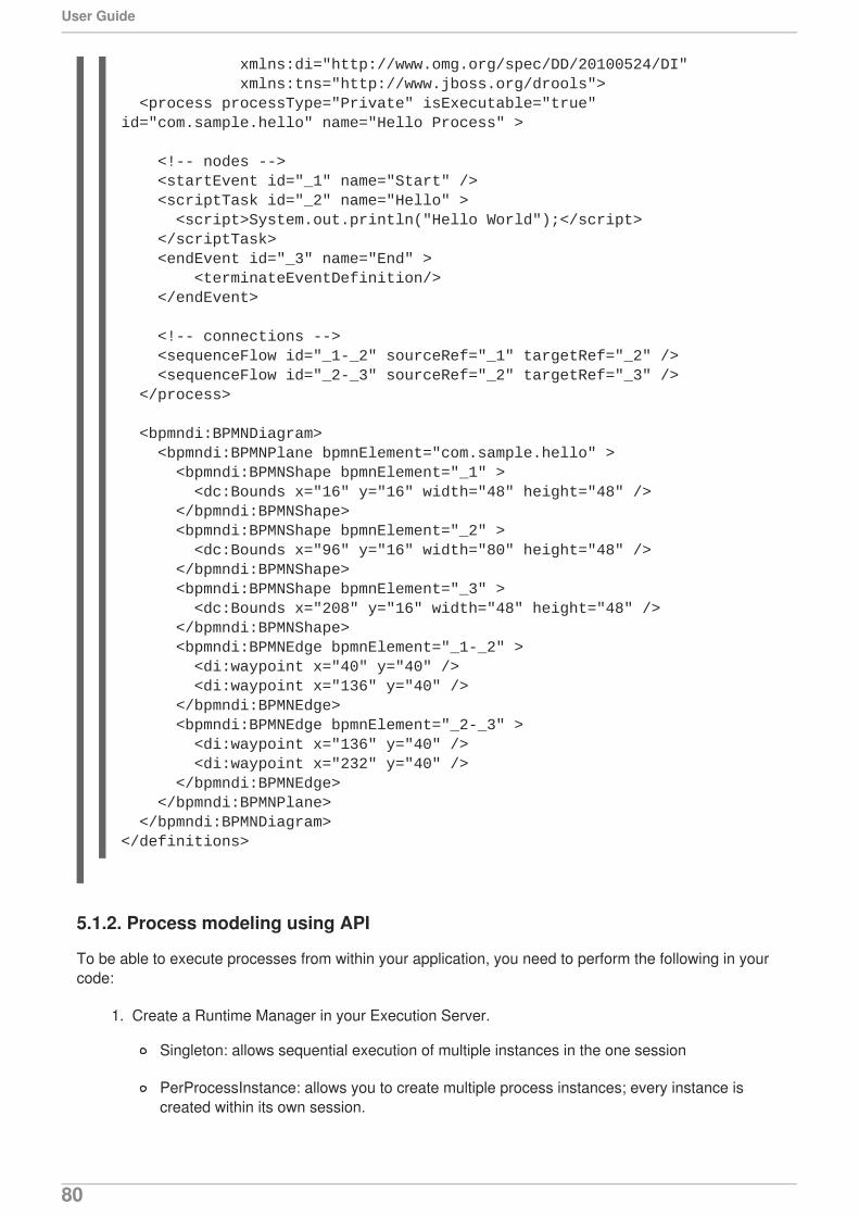
5.1.2. Process modeling using API
To be able to execute processes from within your application, you need to perform the following in yourcode:
1. Create a Runtime Manager in your Execution Server.
Singleton: allows sequential execution of multiple instances in the one session
PerProcessInstance: allows you to create multiple process instances; every instance iscreated within its own session.
xmlns:di="http://www.omg.org/spec/DD/20100524/DI" xmlns:tns="http://www.jboss.org/drools"> <process processType="Private" isExecutable="true" id="com.sample.hello" name="Hello Process" >
<!-- nodes --> <startEvent id="_1" name="Start" /> <scriptTask id="_2" name="Hello" > <script>System.out.println("Hello World");</script> </scriptTask> <endEvent id="_3" name="End" > <terminateEventDefinition/> </endEvent>
<!-- connections --> <sequenceFlow id="_1-_2" sourceRef="_1" targetRef="_2" /> <sequenceFlow id="_2-_3" sourceRef="_2" targetRef="_3" /> </process>
<bpmndi:BPMNDiagram> <bpmndi:BPMNPlane bpmnElement="com.sample.hello" > <bpmndi:BPMNShape bpmnElement="_1" > <dc:Bounds x="16" y="16" width="48" height="48" /> </bpmndi:BPMNShape> <bpmndi:BPMNShape bpmnElement="_2" > <dc:Bounds x="96" y="16" width="80" height="48" /> </bpmndi:BPMNShape> <bpmndi:BPMNShape bpmnElement="_3" > <dc:Bounds x="208" y="16" width="48" height="48" /> </bpmndi:BPMNShape> <bpmndi:BPMNEdge bpmnElement="_1-_2" > <di:waypoint x="40" y="40" /> <di:waypoint x="136" y="40" /> </bpmndi:BPMNEdge> <bpmndi:BPMNEdge bpmnElement="_2-_3" > <di:waypoint x="136" y="40" /> <di:waypoint x="232" y="40" /> </bpmndi:BPMNEdge> </bpmndi:BPMNPlane> </bpmndi:BPMNDiagram></definitions>
User Guide
80
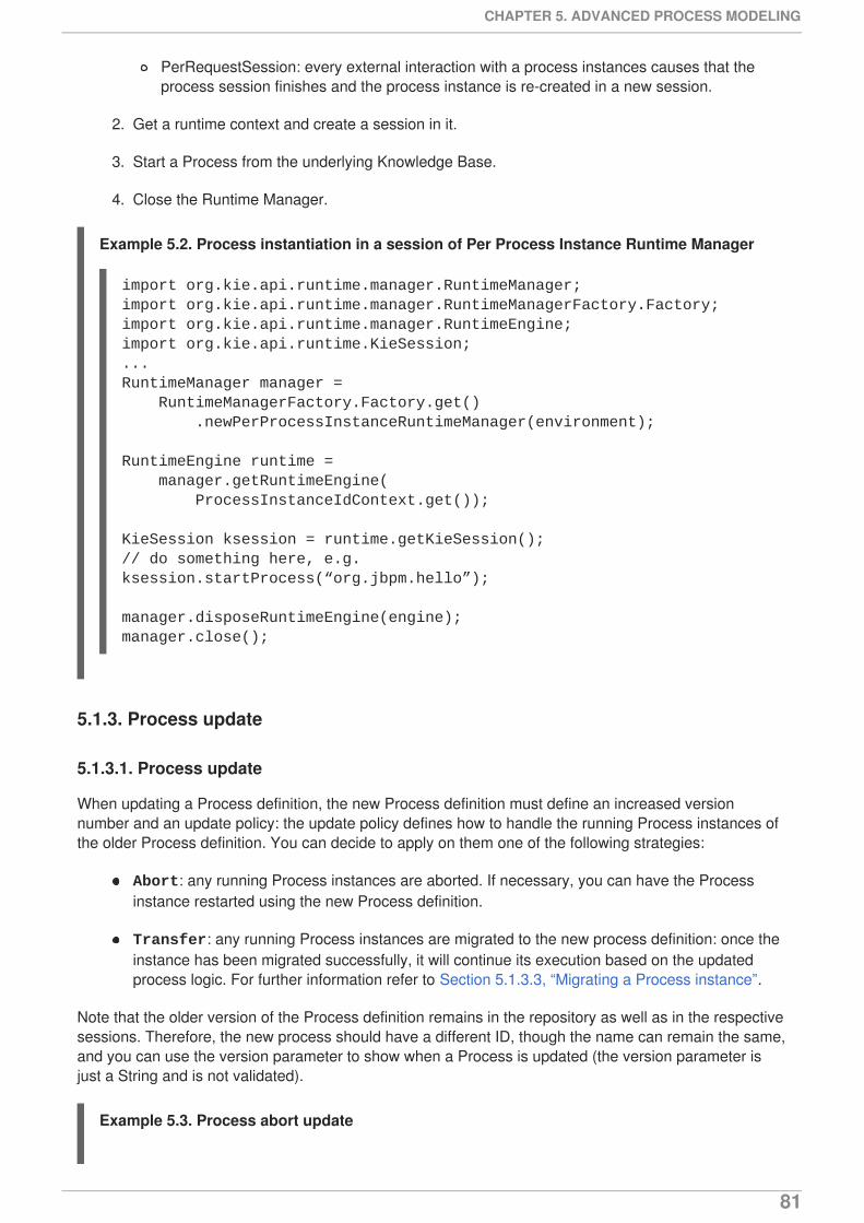
PerRequestSession: every external interaction with a process instances causes that theprocess session finishes and the process instance is re-created in a new session.
2. Get a runtime context and create a session in it.
3. Start a Process from the underlying Knowledge Base.
4. Close the Runtime Manager.
Example 5.2. Process instantiation in a session of Per Process Instance Runtime Manager
5.1.3. Process update
5.1.3.1. Process update
When updating a Process definition, the new Process definition must define an increased versionnumber and an update policy: the update policy defines how to handle the running Process instances ofthe older Process definition. You can decide to apply on them one of the following strategies:
Abort: any running Process instances are aborted. If necessary, you can have the Processinstance restarted using the new Process definition.
Transfer: any running Process instances are migrated to the new process definition: once theinstance has been migrated successfully, it will continue its execution based on the updatedprocess logic. For further information refer to Section 5.1.3.3, “Migrating a Process instance”.
Note that the older version of the Process definition remains in the repository as well as in the respectivesessions. Therefore, the new process should have a different ID, though the name can remain the same,and you can use the version parameter to show when a Process is updated (the version parameter isjust a String and is not validated).
Example 5.3. Process abort update
import org.kie.api.runtime.manager.RuntimeManager;import org.kie.api.runtime.manager.RuntimeManagerFactory.Factory;import org.kie.api.runtime.manager.RuntimeEngine;import org.kie.api.runtime.KieSession;...RuntimeManager manager = RuntimeManagerFactory.Factory.get() .newPerProcessInstanceRuntimeManager(environment);
RuntimeEngine runtime = manager.getRuntimeEngine( ProcessInstanceIdContext.get());
KieSession ksession = runtime.getKieSession();// do something here, e.g.ksession.startProcess(“org.jbpm.hello”);
manager.disposeRuntimeEngine(engine);manager.close();
CHAPTER 5. ADVANCED PROCESS MODELING
81
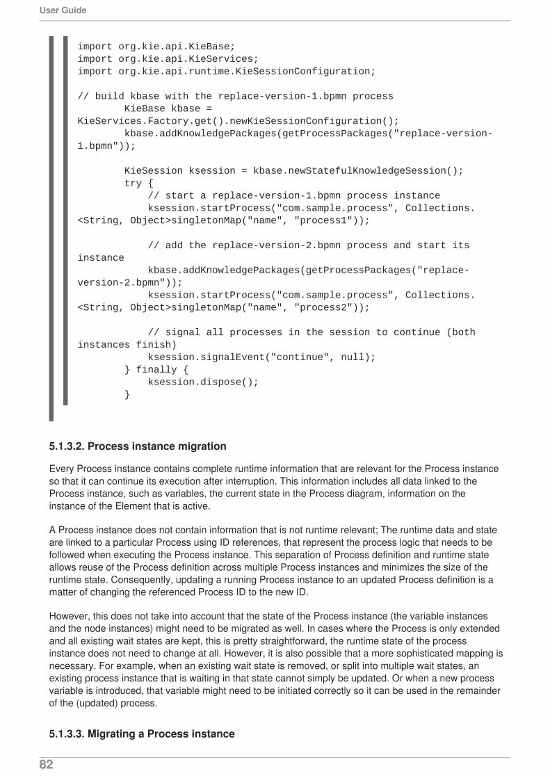
5.1.3.2. Process instance migration
Every Process instance contains complete runtime information that are relevant for the Process instanceso that it can continue its execution after interruption. This information includes all data linked to theProcess instance, such as variables, the current state in the Process diagram, information on theinstance of the Element that is active.
A Process instance does not contain information that is not runtime relevant; The runtime data and stateare linked to a particular Process using ID references, that represent the process logic that needs to befollowed when executing the Process instance. This separation of Process definition and runtime stateallows reuse of the Process definition across multiple Process instances and minimizes the size of theruntime state. Consequently, updating a running Process instance to an updated Process definition is amatter of changing the referenced Process ID to the new ID.
However, this does not take into account that the state of the Process instance (the variable instancesand the node instances) might need to be migrated as well. In cases where the Process is only extendedand all existing wait states are kept, this is pretty straightforward, the runtime state of the processinstance does not need to change at all. However, it is also possible that a more sophisticated mapping isnecessary. For example, when an existing wait state is removed, or split into multiple wait states, anexisting process instance that is waiting in that state cannot simply be updated. Or when a new processvariable is introduced, that variable might need to be initiated correctly so it can be used in the remainderof the (updated) process.
5.1.3.3. Migrating a Process instance
import org.kie.api.KieBase;import org.kie.api.KieServices;import org.kie.api.runtime.KieSessionConfiguration;
// build kbase with the replace-version-1.bpmn process KieBase kbase = KieServices.Factory.get().newKieSessionConfiguration(); kbase.addKnowledgePackages(getProcessPackages("replace-version-1.bpmn"));
KieSession ksession = kbase.newStatefulKnowledgeSession(); try { // start a replace-version-1.bpmn process instance ksession.startProcess("com.sample.process", Collections.<String, Object>singletonMap("name", "process1"));
// add the replace-version-2.bpmn process and start its instance kbase.addKnowledgePackages(getProcessPackages("replace-version-2.bpmn")); ksession.startProcess("com.sample.process", Collections.<String, Object>singletonMap("name", "process2"));
// signal all processes in the session to continue (both instances finish) ksession.signalEvent("continue", null); } finally { ksession.dispose(); }
User Guide
82
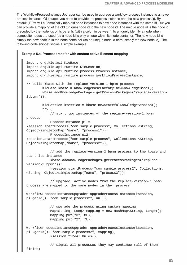
The WorkflowProcessInstanceUpgrader can be used to upgrade a workflow process instance to a newerprocess instance. Of course, you need to provide the process instance and the new process id. Bydefault, jBPM will automatically map old node instances to new node instances with the same id. But youcan provide a mapping of the old (unique) node id to the new node id. The unique node id is the node id,preceded by the node ids of its parents (with a colon in between), to uniquely identify a node whencomposite nodes are used (as a node id is only unique within its node container. The new node id issimply the new node id in the node container (so no unique node id here, simply the new node id). Thefollowing code snippet shows a simple example.
Example 5.4. Process transfer with custom active Element mapping
import org.kie.api.KieBase;import org.kie.api.runtime.KieSession;import org.kie.api.runtime.process.ProcessInstance;import org.kie.api.runtime.process.WorkflowProcessInstance;
// build kbase with the replace-version-1.bpmn process KieBase kbase = KnowledgeBaseFactory.newKnowledgeBase(); kbase.addKnowledgePackages(getProcessPackages("replace-version-1.bpmn"));
KieSession ksession = kbase.newStatefulKnowledgeSession(); try { // start two instances of the replace-version-1.bpmn process ProcessInstance pi = ksession.startProcess("com.sample.process", Collections.<String, Object>singletonMap("name", "process1")); ProcessInstance pi2 = ksession.startProcess("com.sample.process", Collections.<String, Object>singletonMap("name", "process2"));
// add the replace-version-3.bpmn process to the kbase and start its instance kbase.addKnowledgePackages(getProcessPackages("replace-version-3.bpmn")); ksession.startProcess("com.sample.process2", Collections.<String, Object>singletonMap("name", "process3"));
// upgrade: active nodes from the replace-version-1.bpmn process are mapped to the same nodes in the process WorkflowProcessInstanceUpgrader.upgradeProcessInstance(ksession, pi.getId(), "com.sample.process2", null);
// upgrade the process using custom mapping Map<String, Long> mapping = new HashMap<String, Long>(); mapping.put("3", 8L); mapping.put("2", 7L); WorkflowProcessInstanceUpgrader.upgradeProcessInstance(ksession, pi2.getId(), "com.sample.process2", mapping); ksession.fireAllRules();
// signal all processes they may continue (all of them finish)
CHAPTER 5. ADVANCED PROCESS MODELING
83
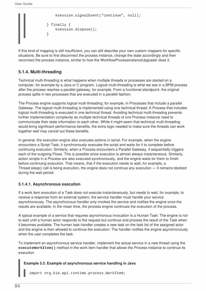
If this kind of mapping is still insufficient, you can still describe your own custom mappers for specificsituations. Be sure to first disconnect the process instance, change the state accordingly and thenreconnect the process instance, similar to how the WorkflowProcessinstanceUpgrader does it.
5.1.4. Multi-threading
Technical multi-threading is what happens when multiple threads or processes are started on acomputer, for example by a Java or C program. Logical multi-threading is what we see in a BPM processafter the process reaches a parallel gateway, for example. From a functional standpoint, the originalprocess splits in two processes that are executed in a parallel fashion.
The Process engine supports logical multi-threading; for example, in Processes that include a parallelGateway. The logical multi-threading is implemented using one technical thread: A Process that includeslogical multi-threading is executed in one technical thread. Avoiding technical multi-threadng preventsfurther implementation complexity as multiple technical threads of one Process instance need tocommunicate their state information to each other. While it might seem that technical multi-threadingwould bring significant performance benefits, the extra logic needed to make sure the threads can worktogether well may cancel out these benefits.
In general, the execution engine also executes actions in serial. For example, when the engineencounters a Script Task, it synchronously executes the script and waits for it to complete beforecontinuing execution. Similarly, when a Process encounters a Parallel Gateway, it sequentially triggerseach of the outgoing Flows. This is possible since execution is almost always instantaneous. Similarly,action scripts in a Process are also executed synchronously, and the engine waits for them to finishbefore continuing execution. That means, that if the execution needs to wait, for example, aThread.sleep() call is being execution, the engine does not continue any execution — it remains blockedduring the wait period.
5.1.4.1. Asynchronous execution
If a work item execution of a Task does not execute instantaneously, but needs to wait, for example, toreceive a response from an external system, the service handler must handle your serviceasynchronously. The asynchronous handler only invokes the service and notifies the engine once theresults are available. In the mean time, the process engine continues the execution of the process.
A typical example of a service that requires asynchronous invocation is a Human Task: The engine is notto wait until a human actor responds to the request but continue and process the result of the Task whenit becomes available. The human task handler creates a new task on the task list of the assigned actorand the engine is then allowed to continue the execution: The handler notifies the engine asynchronouslywhen the user completes the task.
To implement an asynchronous service handler, implement the actual service in a new thread using the executeWorkItem() method in the work item handler that allows the Process instance to continue itsexecution.
Example 5.5. Example of asynchronous service handling in Java
ksession.signalEvent("continue", null);
} finally { ksession.dispose(); }
import org.kie.api.runtime.process.WorkItem;
User Guide
84
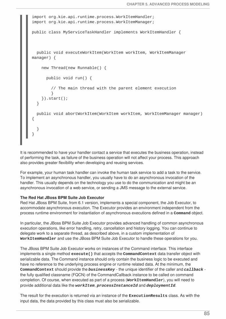
It is recommended to have your handler contact a service that executes the business operation, insteadof performing the task, as failure of the business operation will not affect your process. This approachalso provides greater flexibility when developing and reusing services.
For example, your human task handler can invoke the human task service to add a task to the service.To implement an asynchronous handler, you usually have to do an asynchronous invocation of thehandler. This usually depends on the technology you use to do the communication and might be anasynchronous invocation of a web service, or sending a JMS message to the external service.
The Red Hat JBoss BPM Suite Job ExecutorRed Hat JBoss BPM Suite, from 6.1 version, implements a special component, the Job Executor, toaccommodate asynchronous execution. The Executor provides an environment independent from theprocess runtime environment for instantiation of asynchronous executions defined in a Command object.
In particular, the JBoss BPM Suite Job Executor provides advanced handling of common asynchronousexecution operations, like error handling, retry, cancellation and history logging. You can continue todelegate work to a separate thread, as described above, in a custom implementation of WorkItemHandler and use the JBoss BPM Suite Job Executor to handle these operations for you.
The JBoss BPM Suite Job Executor works on instances of the Command interface. This interfaceimplements a single method execute() that accepts the CommandContext data transfer object withserializable data. The Command instance should only contain the business logic to be executed andhave no reference to the underlying process engine or runtime related data. At the minimum, the CommandContext should provide the businessKey - the unique identifier of the caller and callback -the fully qualified classname (FQCN) of the CommandCallback instance to be called on commandcompletion. Of course, when executed as part of a process (WorkItemHandler), you will need toprovide additional data like the workItem, processInstanceId and deploymentId.
The result for the execution is returned via an instance of the ExecutionResults class. As with theinput data, the data provided by this class must also be serializable.
import org.kie.api.runtime.process.WorkItemHandler;import org.kie.api.runtime.process.WorkItemManager;
public class MyServiceTaskHandler implements WorkItemHandler {
public void executeWorkItem(WorkItem workItem, WorkItemManager manager) {
new Thread(new Runnable() {
public void run() {
// The main thread with the parent element execution } }).start(); }
public void abortWorkItem(WorkItem workItem, WorkItemManager manager) {
}}
CHAPTER 5. ADVANCED PROCESS MODELING
85
Business Central provides a way for you to view the current jobs within the system; to schedule them,cancel them, or view their history. Go to Deploy → Jobs to access this screen. You can even create anew job by clicking on the New Job button.
The Asynchronous WorkItemHandlerRed Hat JBoss BPM Suite 6.1 provides an out of the box asynchronous WorkItemHandler that isbacked by the JBoss BPM Suite Job Executor. All the features that the JBoss BPM Suite Executordelivers are available for background execution within a process instance. There are two ways toconfigure this AsyncWorkItemHandler class:
1. As a generic handler where you provide the command name as part of the work itemparameters. In Business Central while modeling a process, if you need to execute some workitem asynchronously: specify async as the value for the TaskName property, create a data inputcalled CommandClass and assign the FQCN of this CommandClass as the data input.
2. As a specific handler which is created to handle a given type of work item, thus allowing you toregister different instances of AsyncWorkItemHandler for different work items. Commandsare most likely to be dedicated to a particular work item, which allows you to specify the CommandClass at registration time instead of requiring it at design time, as with the firstapproach. But this means that an additional CDI bean that implementsWorkItemHandlerProducer interface needs to be provided and placed on the applicationclasspath so that the CDI container can find it. When you are ready to model your process, setthe value of the TaskName property to the one provided at registration time.
Configuring the JBoss BPM Suite ExecutorThe JBoss BPM Suite executor can be configured to allow fine tunning of its environment via thefollowing system properties:
1. org.kie.executor.disabled: true OR false - enable/disable the executor.
2. org.kie.executor.pool.size: Integer. Specify the thread pool size for the executor, which by defaultis 1.
3. org.kie.executor.retry.count: Integer. Specifies the default number of retries in case of an errorexecuting a job. The default value is 3.
4. org.kie.executor.interval: Integer. Specifies the time to wait between checking for waiting jobs.The default value is 3 seconds.
5. org.kie.executor.timeunit: NANOSECONDS OR MICROSECONDS OR MILLISECONDS ORSECONDS OR MINUTES OR HOURS OR DAYS. Specifies the unit for the interval property.The default is SECONDS.
5.1.4.2. Multiple Sessions and persistence
The simplest way to run multiple Process instances is to run them in one knowledge session. However, itis possible to run multiple Process instances in different knowledge sessions or in different technicalthreads.
When using multiple knowledge session with multiple processes and adding persistence, use a databasethat allows row-level as well as table-level locks: There could be a situation when there are 2 or morethreads running, each within its own knowledge session instance. On each thread, a Processs is beingstarted using the local knowledge session instance. In this use case, a race condition exists in whichboth thread A and thread B have coincidentally simultaneously finished a Process instance. At this point,both thread A and B are commiting changes to the database. If row-level locks are not possible, then thefollowing situation can occur:
User Guide
86
Thread A has a lock on the ProcessInstanceInfo table, having just committed a change to thattable.
Thread A wants a lock on the SessionInfo table in order to commit a change.
Thread B has the opposite situation: It has a lock on the SessionInfo table, having justcommitted a change.
Thread B wants a lock on the ProcessInstanceInfo table, even though Thread A already has alock on it.
This is a deadlock situation which the database and application are not be able to solve, unless row-levellocks are posible and enabled in the database and tables used.
5.1.5. Technical exceptions
Technical exceptions occur when a technical component of a Process acts in an unexpected way. Whenusing Java-based systems, this often results in a Java Exception. As these exceptions cannot behandled using BPMN2, it is important to handle them in expected ways.
The following types of code might throw exceptions:
Code present directly in the process definition
Code that is not part of the product executed during a Process
Code that interacts with a technical component outside of the Process Engine
This includes the following:
Code in Element properties, such as the Script property of a Script Task element or in thedefinitions of the interception actions, that is, the onEntry and onExit properties
Code in WorkItemHandlers associated with task and task-type nodes
Code in Element propertiesExceptions thrown by code defined in Element properties can cause the Process instance to fail in anunrecoverable way. Often, it is the code that starts the Process that will end up throwing the exceptiongenerated by a Process without returning a reference to the Process instance. Such code includes forexample the onEntry and onExit properties, Script defined for the Script Task, etc.
Therefore, it is important to limit the scope of the code in these Elements so that is operates only overProcess variables. Using a scriptTask to interact with a different technical component, such as adatabase or web service has significant risks because any exceptions thrown will corrupt or abort theProcess instance.
To interact with other systems, use task Elements, serviceTask Elements and other task-typeElements. Do not use the scriptTask nodes for these purposes.
NOTE
If the script defined in a scriptTask causes the problem, the Process Engine usuallythrows the WorkflowRuntimeException with information on the Process (refer toSection 5.1.5.1.5, “Extracting information from WorkflowRuntimeException”).
CHAPTER 5. ADVANCED PROCESS MODELING
87

Code in WorkItemHandlersWorkItemHandlers are used when your Process interacts with other technical systems (for moreinformation on WorkItemHandlers refer to Section 4.14.1, “Work item definition”).
You can either build exception handling into your own WorkItemhandler implementations or wrap yourimplementation into the handler decorator classes (for examples and detailed information refer toSection 5.1.5.1.2, “Exception handling classes”). These classes include the logic that is executed whenan exception is thrown during the execution or abortion of a work item:
SignallingTaskHandlerDecorator
catches the exception and signals it to the Process instance using a configurable event type when theexecuteWorkItem() or abortWorkItem methods of the original WorkItemHandler instancethrow an exception. The exception thrown is passed as part of the event. This functionality can bealso used to signal to an Event SubProcess defined in the Process definition.
LoggingTaskHandlerDecorator
logs error about any exceptions thrown by the executeWorkItem() and abortWorkItem()methods. It also saves any exceptions thrown to an internal list so that they can be retrieved later forinspection or further logging. The content and format of the message logged are configurable.
While the classes described above covers most cases involving exception handling as it catches anythrowable objects, you might still want to write a custom WorkItemHandler that includes exceptionhandling logic. In such a case, consider the following:
Does the implementation catch all exceptions the code could return?
Does the implementation complete or abort the work item after an exception has been caught oruses a mechanisms to retry the process later (in some cases, incomplete process instancesmight be acceptable)?
Does the implementation define any other actions that need to be taken when an exception iscaught? Would it be beneficial to interact with other technical systems? Should a Sub-Processbe triggered to handle the exception?
IMPORTANT
If WorkItemManager to signals that the work item has been completed or aborted, makesure the signal is sent after any signals to the Process instance were sent. Depending onhow your Process definition, calling WorkItemManager.completeWorkItem() orWorkItemManager.abortWorkItem() triggers the completion of the Process instance asthese methods trigger further execution of the Process execution flow.
5.1.5.1. Technical exception examples
5.1.5.1.1. Service Task handlers
The example involves a Throwing Error Intermediate Event caught by an Error Event Sub-Process.
When the Throwing Error Intermediate Event throws the Error, the Process instance is interrupted:
1. Execution of the Process instance stops: no other parts of the Process are executed.
2. The Process instance finishes as ABORTED.
User Guide
88
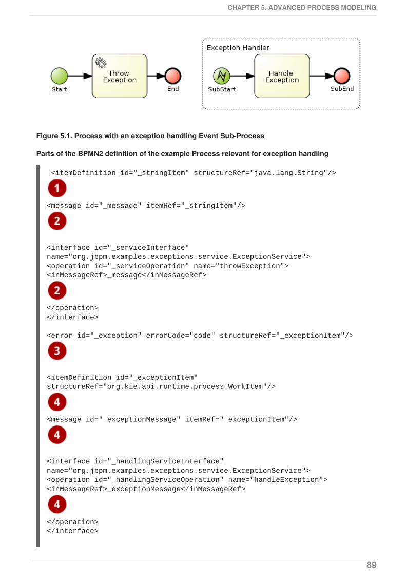
Figure 5.1. Process with an exception handling Event Sub-Process
Parts of the BPMN2 definition of the example Process relevant for exception handling
<itemDefinition id="_stringItem" structureRef="java.lang.String"/>
<message id="_message" itemRef="_stringItem"/>
<interface id="_serviceInterface" name="org.jbpm.examples.exceptions.service.ExceptionService"><operation id="_serviceOperation" name="throwException"><inMessageRef>_message</inMessageRef>
</operation></interface>
<error id="_exception" errorCode="code" structureRef="_exceptionItem"/>
<itemDefinition id="_exceptionItem" structureRef="org.kie.api.runtime.process.WorkItem"/>
<message id="_exceptionMessage" itemRef="_exceptionItem"/>
<interface id="_handlingServiceInterface" name="org.jbpm.examples.exceptions.service.ExceptionService"><operation id="_handlingServiceOperation" name="handleException"><inMessageRef>_exceptionMessage</inMessageRef>
</operation></interface>
CHAPTER 5. ADVANCED PROCESS MODELING
89
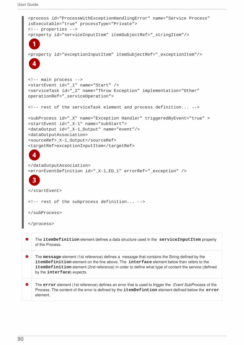
The itemDefinition element defines a data structure used in the serviceInputItem propertyof the Process.
The message element (1st reference) defines a message that contains the String defined by the itemDefinition element on the line above. The interface element below then refers to the itemDefinition element (2nd reference) in order to define what type of content the service (definedby the interface) expects.
The error element (1st reference) defines an error that is used to trigger the Event SubProcess of theProcess. The content of the error is defined by the itemDefintion element defined below the errorelement.
<process id="ProcessWithExceptionHandlingError" name="Service Process" isExecutable="true" processType="Private"><!-- properties --><property id="serviceInputItem" itemSubjectRef="_stringItem"/>
<property id="exceptionInputItem" itemSubjectRef="_exceptionItem"/>
<!-- main process --><startEvent id="_1" name="Start" /><serviceTask id="_2" name="Throw Exception" implementation="Other" operationRef="_serviceOperation">
<!-- rest of the serviceTask element and process definition... -->
<subProcess id="_X" name="Exception Handler" triggeredByEvent="true" ><startEvent id="_X-1" name="subStart"><dataOutput id="_X-1_Output" name="event"/><dataOutputAssociation><sourceRef>_X-1_Output</sourceRef><targetRef>exceptionInputItem</targetRef>
</dataOutputAssociation><errorEventDefinition id="_X-1_ED_1" errorRef="_exception" />
</startEvent>
<!-- rest of the subprocess definition... -->
</subProcess>
</process>
User Guide
90
This itemDefinition element (1st reference) defines an item that contains a WorkItem instance.The message element (2nd reference) then defines a message that uses this item definition to define itscontent. The interface element below that refers to the message definition (3rd reference) in orderto define the type of content that the service expects.
In the Process element itself, a property element (4th reference) that contains the initial itemDefinition. This allows the Event SubProcess to store the error it receives in that property (5threference).
5.1.5.1.2. Exception handling classes
The serviceTask tasks use the org.jbpm.bpmn2.handler.ServiceTaskHandler class as its task handlerclass unless the serviceTask defines a custom WorkItemHandler implementation.
To catch and handle any technical exceptions a WorkItemHandler of a task might throw, wrap ordecorate the handler class with a SignallingTaskHandlerDecorator instance.
IMPORTANT
When sending a signal of an event to the Process Engine, consider the rules for signalingprocess events:
Error events are signaled by sending an Error-errorCode attribute value value to the session.
Signal events are signaled by sending the name of the signal to the session.
If you wanted to send an error event to a Boundary Catch Error Event, the errortype should be of the format: "Error-" + $AttachedNodeID + "-" + $ERROR_CODE. For example, Error-SubProcess_1-888 would be a validerror type.
However, this is NOT a recommended practice because sending the signal thisway bypasses parts of the boundary error event functionality and it relies oninternal implementation details that might be changed in the future. For a way toprogrammatically trigger a boundary error event when an Exception is thrown in WorkItemHandler see this KnowledgeBase article.
Example 5.6. Using SignallingTaskHandlerDecorator
The ServiceTaskHandler calls the ExceptionService.throwException() method to throwan exception (refer to the _handlingServiceInterface interface element in the BPMN2).
The SignallingTaskHandlerDecorator that wraps the ServiceTaskHandler sends to theProcess instance the error with the set error code.
import java.util.HashMap;import java.util.Map;
import org.jbpm.bpmn2.handler.ServiceTaskHandler;import org.jbpm.bpmn2.handler.SignallingTaskHandlerDecorator;import org.jbpm.examples.exceptions.service.ExceptionService;import org.kie.api.KieBase;
CHAPTER 5. ADVANCED PROCESS MODELING
91
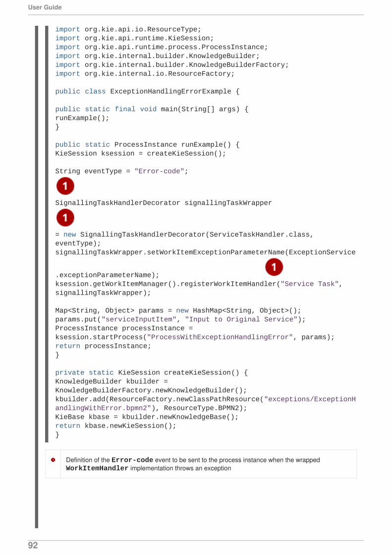
Definition of the Error-code event to be sent to the process instance when the wrapped WorkItemHandler implementation throws an exception
import org.kie.api.io.ResourceType;import org.kie.api.runtime.KieSession;import org.kie.api.runtime.process.ProcessInstance;import org.kie.internal.builder.KnowledgeBuilder;import org.kie.internal.builder.KnowledgeBuilderFactory;import org.kie.internal.io.ResourceFactory;
public class ExceptionHandlingErrorExample {
public static final void main(String[] args) {runExample();}
public static ProcessInstance runExample() {KieSession ksession = createKieSession();
String eventType = "Error-code";
SignallingTaskHandlerDecorator signallingTaskWrapper
= new SignallingTaskHandlerDecorator(ServiceTaskHandler.class, eventType);signallingTaskWrapper.setWorkItemExceptionParameterName(ExceptionService
.exceptionParameterName); ksession.getWorkItemManager().registerWorkItemHandler("Service Task", signallingTaskWrapper);
Map<String, Object> params = new HashMap<String, Object>();params.put("serviceInputItem", "Input to Original Service");ProcessInstance processInstance = ksession.startProcess("ProcessWithExceptionHandlingError", params);return processInstance;}
private static KieSession createKieSession() {KnowledgeBuilder kbuilder = KnowledgeBuilderFactory.newKnowledgeBuilder();kbuilder.add(ResourceFactory.newClassPathResource("exceptions/ExceptionHandlingWithError.bpmn2"), ResourceType.BPMN2);KieBase kbase = kbuilder.newKnowledgeBase();return kbase.newKieSession();}
User Guide
92
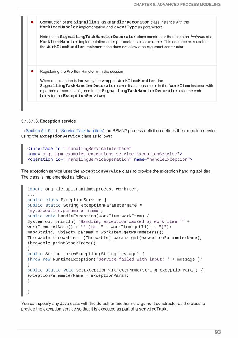
Construction of the SignallingTaskHandlerDecorator class instance with the WorkItemHandler implementation and eventType as parameters
Note that a SignallingTaskHandlerDecorator class constructor that takes an instance of a WorkItemHandler implementation as its parameter is also available. This constructor is useful ifthe WorkItemHandler implementation does not allow a no-argument constructor.
Registering the WorItemHandler with the session
When an exception is thrown by the wrapped WorkItemHandler, the SignallingTaskHandlerDecorator saves it as a parameter in the WorkItem instance witha parameter name configured in the SignallingTaskHandlerDecorator (see the codebelow for the ExceptionService).
5.1.5.1.3. Exception service
In Section 5.1.5.1.1, “Service Task handlers” the BPMN2 process definition defines the exception serviceusing the ExceptionService class as follows:
The exception service uses the ExceptionService class to provide the exception handling abilities.The class is implemented as follows:
You can specify any Java class with the default or another no-argument constructor as the class toprovide the exception service so that it is executed as part of a serviceTask.
<interface id="_handlingServiceInterface" name="org.jbpm.examples.exceptions.service.ExceptionService"><operation id="_handlingServiceOperation" name="handleException">
import org.kie.api.runtime.process.WorkItem;... public class ExceptionService {public static String exceptionParameterName = "my.exception.parameter.name";public void handleException(WorkItem workItem) {System.out.println( "Handling exception caused by work item '" + workItem.getName() + "' (id: " + workItem.getId() + ")");Map<String, Object> params = workItem.getParameters();Throwable throwable = (Throwable) params.get(exceptionParameterName);throwable.printStackTrace();}public String throwException(String message) {throw new RuntimeException("Service failed with input: " + message );}public static void setExceptionParameterName(String exceptionParam) {exceptionParameterName = exceptionParam;}
}
CHAPTER 5. ADVANCED PROCESS MODELING
93
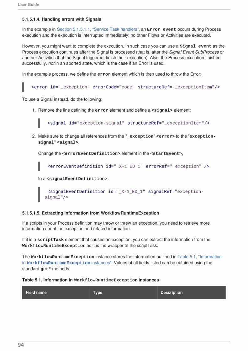
5.1.5.1.4. Handling errors with Signals
In the example in Section 5.1.5.1.1, “Service Task handlers”, an Error event occurs during Processexecution and the execution is interrupted immediately: no other Flows or Activities are executed.
However, you might want to complete the execution. In such case you can use a Signal event as theProcess execution continues after the Signal is processed (that is, after the Signal Event SubProcess oranother Activities that the Signal triggered, finish their execution). Also, the Process execution finishedsuccessfully, not in an aborted state, which is the case if an Error is used.
In the example process, we define the error element which is then used to throw the Error:
To use a Signal instead, do the following:
1. Remove the line defining the error element and define a <signal> element:
2. Make sure to change all references from the "_exception" <error> to the "exception-signal" <signal>.
Change the <errorEventDefinition> element in the <startEvent>,
to a <signalEventDefinition>:
5.1.5.1.5. Extracting information from WorkflowRuntimeException
If a scripts in your Process definition may throw or threw an exception, you need to retrieve moreinformation about the exception and related information.
If it is a scriptTask element that causes an exception, you can extract the information from the WorkflowRuntimeException as it is the wrapper of the scriptTask.
The WorkflowRuntimeException instance stores the information outlined in Table 5.1, “Informationin WorkflowRuntimeException instances”. Values of all fields listed can be obtained using thestandard get* methods.
Table 5.1. Information in WorkflowRuntimeException instances
Field name Type Description
<error id="_exception" errorCode="code" structureRef="_exceptionItem"/>
<signal id="exception-signal" structureRef="_exceptionItem"/>
<errorEventDefinition id="_X-1_ED_1" errorRef="_exception" />
<signalEventDefinition id="_X-1_ED_1" signalRef="exception-signal"/>
User Guide
94
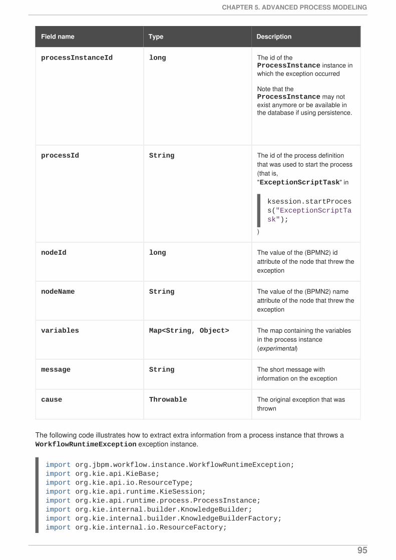
processInstanceId long The id of the ProcessInstance instance inwhich the exception occurred
Note that the ProcessInstance may notexist anymore or be available inthe database if using persistence.
processId String The id of the process definitionthat was used to start the process(that is,"ExceptionScriptTask" in
)
nodeId long The value of the (BPMN2) idattribute of the node that threw theexception
nodeName String The value of the (BPMN2) nameattribute of the node that threw theexception
variables Map<String, Object> The map containing the variablesin the process instance(experimental)
message String The short message withinformation on the exception
cause Throwable The original exception that wasthrown
Field name Type Description
The following code illustrates how to extract extra information from a process instance that throws a WorkflowRuntimeException exception instance.
ksession.startProcess("ExceptionScriptTask");
import org.jbpm.workflow.instance.WorkflowRuntimeException;import org.kie.api.KieBase;import org.kie.api.io.ResourceType;import org.kie.api.runtime.KieSession;import org.kie.api.runtime.process.ProcessInstance;import org.kie.internal.builder.KnowledgeBuilder;import org.kie.internal.builder.KnowledgeBuilderFactory;import org.kie.internal.io.ResourceFactory;
CHAPTER 5. ADVANCED PROCESS MODELING
95
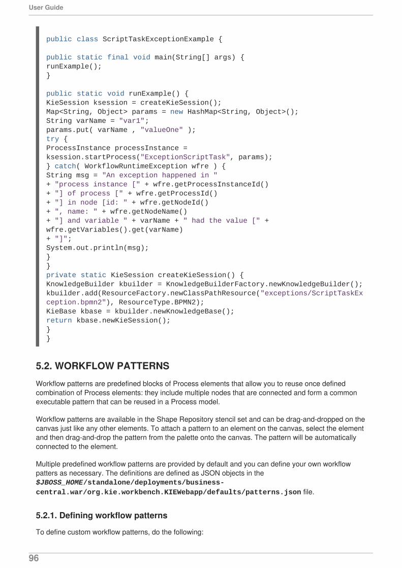
5.2. WORKFLOW PATTERNS
Workflow patterns are predefined blocks of Process elements that allow you to reuse once definedcombination of Process elements: they include multiple nodes that are connected and form a commonexecutable pattern that can be reused in a Process model.
Workflow patterns are available in the Shape Repository stencil set and can be drag-and-dropped on thecanvas just like any other elements. To attach a pattern to an element on the canvas, select the elementand then drag-and-drop the pattern from the palette onto the canvas. The pattern will be automaticallyconnected to the element.
Multiple predefined workflow patterns are provided by default and you can define your own workflowpatters as necessary. The definitions are defined as JSON objects in the $JBOSS_HOME/standalone/deployments/business-central.war/org.kie.workbench.KIEWebapp/defaults/patterns.json file.
5.2.1. Defining workflow patterns
To define custom workflow patterns, do the following:
public class ScriptTaskExceptionExample {
public static final void main(String[] args) {runExample();}
public static void runExample() {KieSession ksession = createKieSession();Map<String, Object> params = new HashMap<String, Object>();String varName = "var1";params.put( varName , "valueOne" );try {ProcessInstance processInstance = ksession.startProcess("ExceptionScriptTask", params);} catch( WorkflowRuntimeException wfre ) {String msg = "An exception happened in "+ "process instance [" + wfre.getProcessInstanceId()+ "] of process [" + wfre.getProcessId()+ "] in node [id: " + wfre.getNodeId()+ ", name: " + wfre.getNodeName()+ "] and variable " + varName + " had the value [" + wfre.getVariables().get(varName)+ "]";System.out.println(msg);}}private static KieSession createKieSession() {KnowledgeBuilder kbuilder = KnowledgeBuilderFactory.newKnowledgeBuilder();kbuilder.add(ResourceFactory.newClassPathResource("exceptions/ScriptTaskException.bpmn2"), ResourceType.BPMN2);KieBase kbase = kbuilder.newKnowledgeBase();return kbase.newKieSession();}}
User Guide
96

1. In the stencil set of the Process Designer, locate the workflow pattern that resembles most toand that will use as base for your workflow pattern.
2. Open the $JBOSS_HOME/standalone/deployments/business-central.war/org.kie.workbench.KIEWebapp/defaults /patterns.json file in atext editor.
3. Locate the JSON object with the description property set to the base workflow pattern name (forexample, "description" : "Sequence Pattern").
4. Copy the JSON object and modify its elements as needed. Note that all the JSON objects arenested in a pair of square brackets and are comma separated.
CHAPTER 5. ADVANCED PROCESS MODELING
97

CHAPTER 6. SOCIAL EVENTSIn Red Hat JBoss BPM Suite 6.1, users can follow other users and gain an insight into what activities arebeing performed by that user. They can also listen for and follow timelines of regular events. Thiscapability comes via the implementation of a Social Activities framework. This framework ensures thatevent notifications are generated by different activities within the system and that these notifications arebroadcast for registered actors to view.
Multiple activities trigger events. These include: new repository creation, adding and updating resourcesand adding and updating processes. With the right credentials, a user can view these notifications oncethey are logged into Business Central.
FOLLOW USERTo follow a user, search for the user by entering his name in the search box in the People perspective.You get to this perspective by navigating to it from Home → People.
You must know the login name of the other user that you want to follow. As you enter the name in thesearch box, the system will try and auto-complete the name for you and display matches based on yourpartial entry. Select the user that you want to follow from these matches and the perspective will updateto display more details about this user.
You can choose to follow the user by clicking on the Follow button. The perspective refreshes toshowcase the user details and their recent activities.
ACTIVITY TIMELINEClick on Home → Timeline to see a list of recent assets that have been modified (in the left handwindow) and a list of changes made in the selected repository in the right hand side. You can click on theassets to directly open the editor for the assets (if you have the right permissions).
User Guide
98

PART II. SIMULATION AND TESTING
PART II. SIMULATION AND TESTING
99
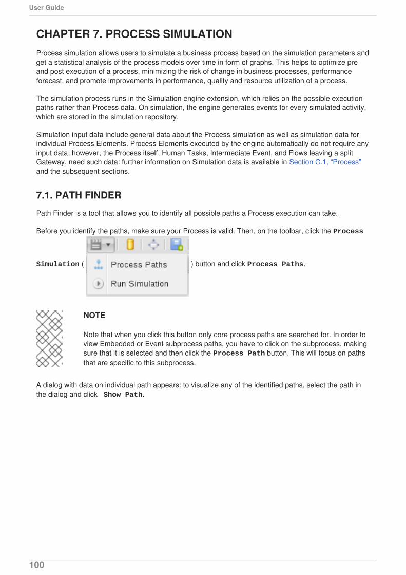
CHAPTER 7. PROCESS SIMULATIONProcess simulation allows users to simulate a business process based on the simulation parameters andget a statistical analysis of the process models over time in form of graphs. This helps to optimize preand post execution of a process, minimizing the risk of change in business processes, performanceforecast, and promote improvements in performance, quality and resource utilization of a process.
The simulation process runs in the Simulation engine extension, which relies on the possible executionpaths rather than Process data. On simulation, the engine generates events for every simulated activity,which are stored in the simulation repository.
Simulation input data include general data about the Process simulation as well as simulation data forindividual Process Elements. Process Elements executed by the engine automatically do not require anyinput data; however, the Process itself, Human Tasks, Intermediate Event, and Flows leaving a splitGateway, need such data: further information on Simulation data is available in Section C.1, “Process”and the subsequent sections.
7.1. PATH FINDER
Path Finder is a tool that allows you to identify all possible paths a Process execution can take.
Before you identify the paths, make sure your Process is valid. Then, on the toolbar, click the Process
Simulation ( ) button and click Process Paths.
NOTE
Note that when you click this button only core process paths are searched for. In order toview Embedded or Event subprocess paths, you have to click on the subprocess, makingsure that it is selected and then click the Process Path button. This will focus on pathsthat are specific to this subprocess.
A dialog with data on individual path appears: to visualize any of the identified paths, select the path inthe dialog and click Show Path.
User Guide
100
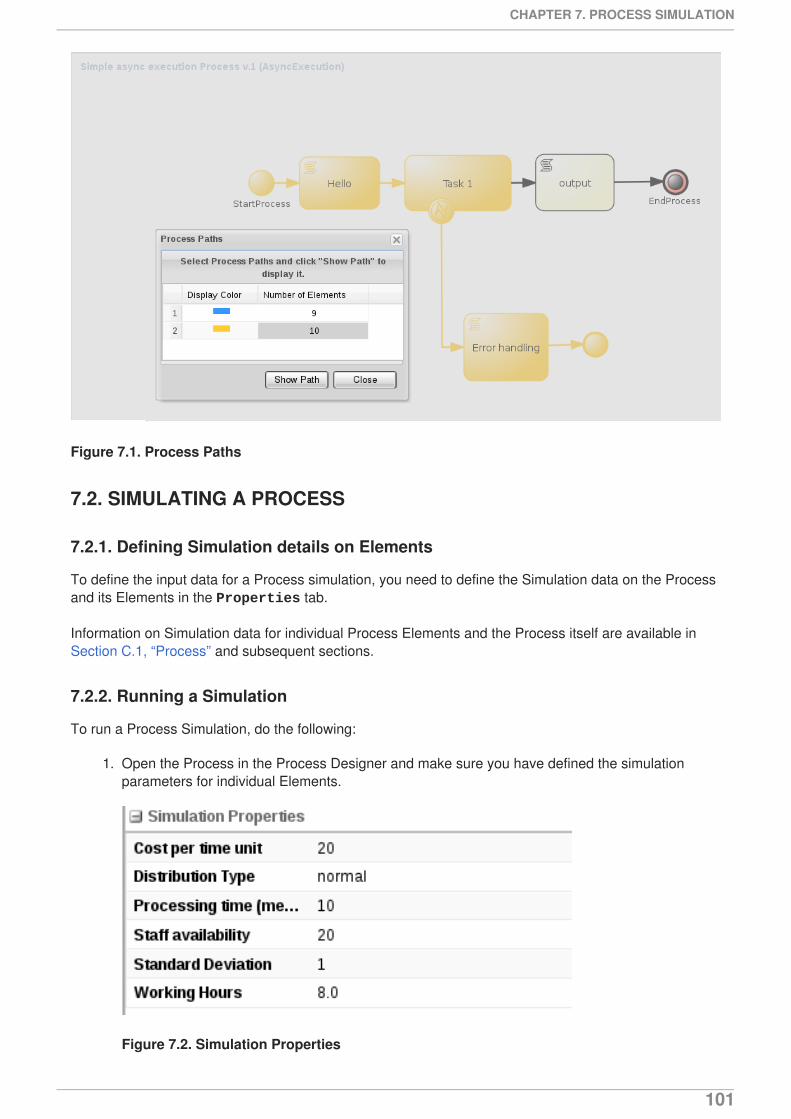
Figure 7.1. Process Paths
7.2. SIMULATING A PROCESS
7.2.1. Defining Simulation details on Elements
To define the input data for a Process simulation, you need to define the Simulation data on the Processand its Elements in the Properties tab.
Information on Simulation data for individual Process Elements and the Process itself are available inSection C.1, “Process” and subsequent sections.
7.2.2. Running a Simulation
To run a Process Simulation, do the following:
1. Open the Process in the Process Designer and make sure you have defined the simulationparameters for individual Elements.
Figure 7.2. Simulation Properties
CHAPTER 7. PROCESS SIMULATION
101
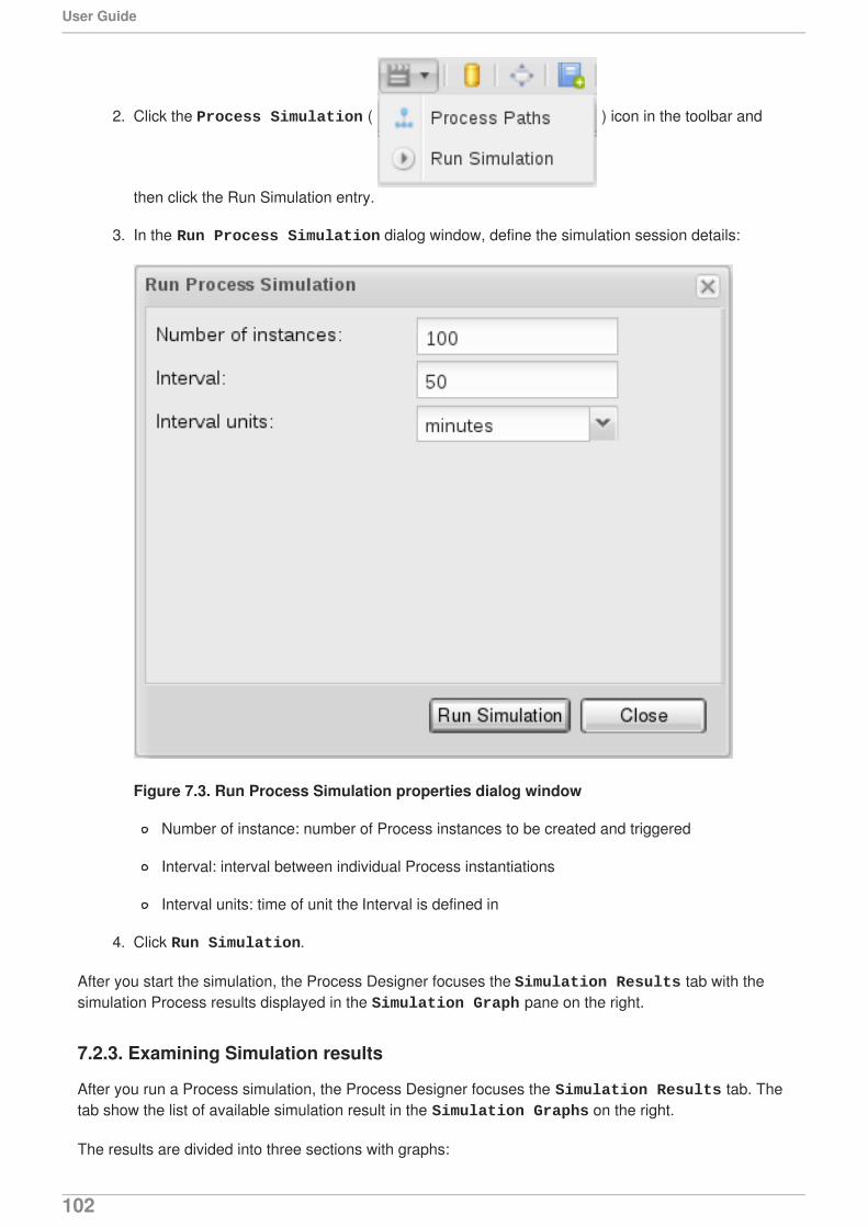
2. Click the Process Simulation ( ) icon in the toolbar and
then click the Run Simulation entry.
3. In the Run Process Simulation dialog window, define the simulation session details:
Figure 7.3. Run Process Simulation properties dialog window
Number of instance: number of Process instances to be created and triggered
Interval: interval between individual Process instantiations
Interval units: time of unit the Interval is defined in
4. Click Run Simulation.
After you start the simulation, the Process Designer focuses the Simulation Results tab with thesimulation Process results displayed in the Simulation Graph pane on the right.
7.2.3. Examining Simulation results
After you run a Process simulation, the Process Designer focuses the Simulation Results tab. Thetab show the list of available simulation result in the Simulation Graphs on the right.
The results are divided into three sections with graphs:
User Guide
102
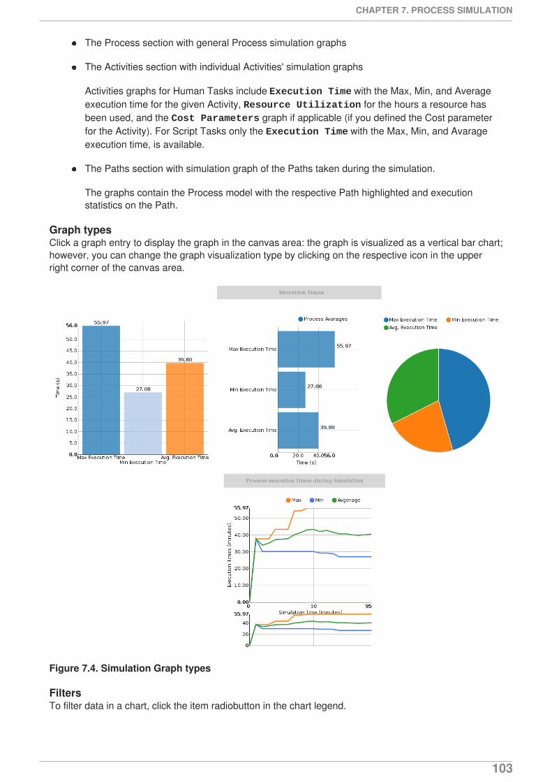
The Process section with general Process simulation graphs
The Activities section with individual Activities' simulation graphs
Activities graphs for Human Tasks include Execution Time with the Max, Min, and Averageexecution time for the given Activity, Resource Utilization for the hours a resource hasbeen used, and the Cost Parameters graph if applicable (if you defined the Cost parameterfor the Activity). For Script Tasks only the Execution Time with the Max, Min, and Avarageexecution time, is available.
The Paths section with simulation graph of the Paths taken during the simulation.
The graphs contain the Process model with the respective Path highlighted and executionstatistics on the Path.
Graph typesClick a graph entry to display the graph in the canvas area: the graph is visualized as a vertical bar chart;however, you can change the graph visualization type by clicking on the respective icon in the upperright corner of the canvas area.
Figure 7.4. Simulation Graph types
FiltersTo filter data in a chart, click the item radiobutton in the chart legend.
CHAPTER 7. PROCESS SIMULATION
103
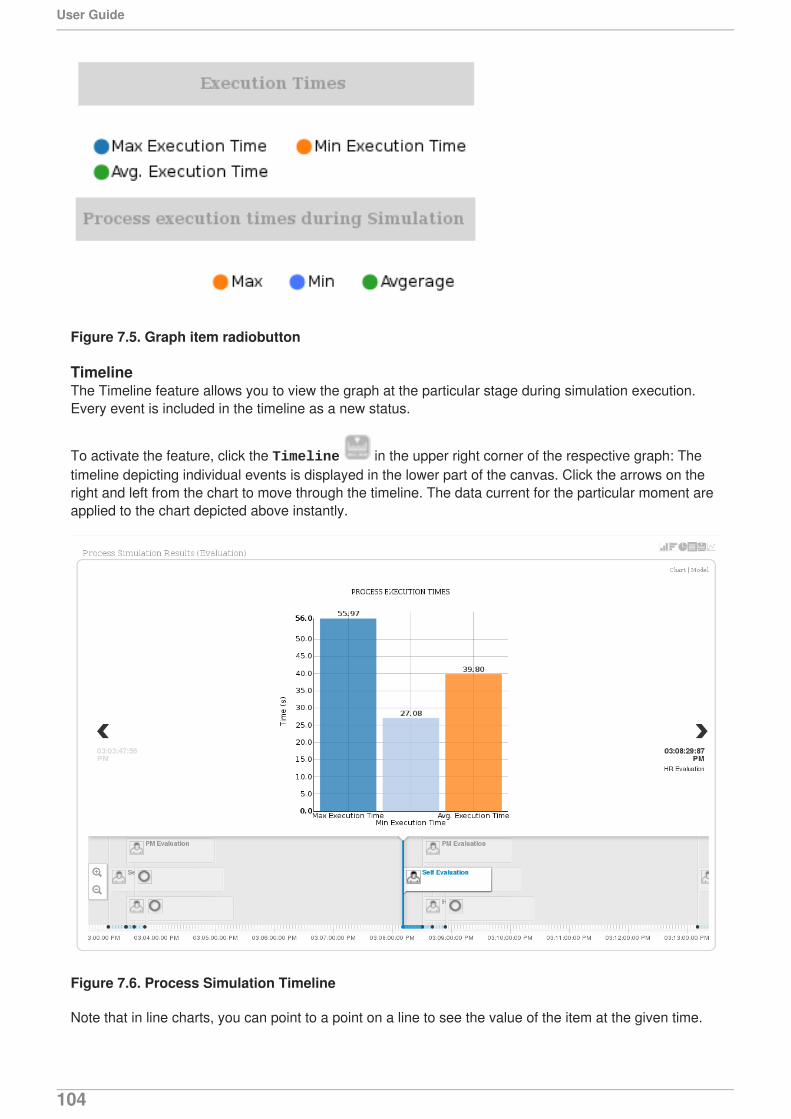
Figure 7.5. Graph item radiobutton
TimelineThe Timeline feature allows you to view the graph at the particular stage during simulation execution.Every event is included in the timeline as a new status.
To activate the feature, click the Timeline in the upper right corner of the respective graph: Thetimeline depicting individual events is displayed in the lower part of the canvas. Click the arrows on theright and left from the chart to move through the timeline. The data current for the particular moment areapplied to the chart depicted above instantly.
Figure 7.6. Process Simulation Timeline
Note that in line charts, you can point to a point on a line to see the value of the item at the given time.
User Guide
104
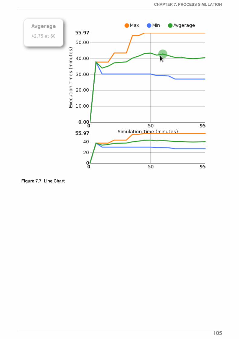
Figure 7.7. Line Chart
CHAPTER 7. PROCESS SIMULATION
105
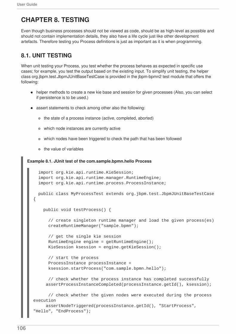
CHAPTER 8. TESTINGEven though business processes should not be viewed as code, should be as high-level as possible andshould not contain implementation details, they also have a life cycle just like other developmentartefacts. Therefore testing you Process definitions is just as important as it is when programming.
8.1. UNIT TESTING
When unit testing your Process, you test whether the process behaves as expected in specific usecases; for example, you test the output based on the existing input. To simplify unit testing, the helperclass org.jbpm.test.JbpmJUnitBaseTestCase is provided in the jbpm-bpmn2 test module that offers thefollowing:
helper methods to create a new kie base and session for given processes (Also, you can selectif persistence is to be used.)
assert statements to check among other also the following:
the state of a process instance (active, completed, aborted)
which node instances are currently active
which nodes have been triggered to check the path that has been followed
the value of variables
Example 8.1. JUnit test of the com.sample.bpmn.hello Process
import org.kie.api.runtime.KieSession; import org.kie.api.runtime.manager.RuntimeEngine; import org.kie.api.runtime.process.ProcessInstance; public class MyProcessTest extends org.jbpm.test.JbpmJUnitBaseTestCase { public void testProcess() {
// create singleton runtime manager and load the given process(es) createRuntimeManager("sample.bpmn"); // get the single kie session RuntimeEngine engine = getRuntimeEngine(); KieSession ksession = engine.getKieSession(); // start the process ProcessInstance processInstance = ksession.startProcess("com.sample.bpmn.hello"); // check whether the process instance has completed successfully assertProcessInstanceCompleted(processInstance.getId(), ksession); // check whether the given nodes were executed during the process execution assertNodeTriggered(processInstance.getId(), "StartProcess", "Hello", "EndProcess");
User Guide
106
The JUnit test will create a new session, start the com.sample.bpmn.hello process and verify whetherthe Process instance completed successfully and whether the nodes StartProcess, Hello,EndProcess have been executed.
8.2. SESSION CREATION
To create a session, it is required to first create a RuntimeManager and RuntimeEngine from which youwill get the session. The following methods can be used to create RuntimeManager:
createRuntimeManager(String... process) creates default configuration of theRuntimeManager with singleton strategy and all processes added to the kie base. There will onlybe one RuntimeManager created during single test and the processes shall be added to the kiebase.
createRuntimeManager(Strategy strategy, String identifier, String... process) creates default configuration of RuntimeManager with given strategy and allprocesses being added to the kie base. Strategy selects the strategies that are supported, andidentifier identifies the RuntimeManager.
createRuntimeManager(Map<String, ResourceType> resources) creates defaultconfiguration of RuntimeManager with singleton strategy and all resources being added to kiebase. The resources code identifies the processes, rules, etc that shall be added to the kiebase.
createRuntimeManager(Map<String, ResourceType> resources, String identifier) creates default configuration of RuntimeManager with singleton strategy and allresources added to kie base. Like the method above but with an identifier that identifies theRuntimeManager.
createRuntimeManager(Strategy strategy, Map<String, ResourceType> resources) creates default configuration of RuntimeManager with given strategy and allresources being added to the kie base. There will be only one RuntimeManager created duringsingle test. The strategy code is the selected strategy of those that are supported. The resources code are all the resources that shall be added to the kie base.
createRuntimeManager(Strategy strategy, Map<String, ResourceType> resources, String identifier) creates default configuration of RuntimeManager withgiven strategy and all resources being added to kie base. There will be only oneRuntimeManager created during single test. The strategy code selects the supportedstrategies. The resources code identifies the resources that shall be added to the kie base.The identifier code identifies the RuntimeManger.
createRuntimeManager(Strategy strategy, Map<String, ResourceType< resources, RuntimeEnvironment environment, String identifier) is the lowestlevel of creation of RuntimeManager that expects to get RuntimeEnvironment to be given as anargument. It does not assume any particular configuration; that is, it allows you to configureevery single piece of RuntimeManager manually. The strategy code selects the strategies of
}}
CHAPTER 8. TESTING
107
those that are supported. The resources code identifies the resources added to the kie base.The environment code is the runtime environment used for RuntimeManager creation. The identifier code identifies the RuntimeManager.
The following methods can be used to get RuntimeEngine:
getRuntimeEngine() returns a new RuntimeEngline built from the manager of the test case.It uses EmptyContext that is suitable for the following strategies: singleton and request.
getRuntimeEngine(Context<?> context) returns a new RuntimeEngine built from themanager of the test case. Common use case would be to maintain the same session for theprocess instance and thus a ProcessInstanceIdContext shall be used. The context code is theinstance of the context that shall be used to create RuntimeManager.
8.2.1. Assertions
The following assertions are available for testing the current state of a process instance:
assertProcessInstanceActive(long processInstanceId, KieSession ksession): checks whether theProcess instance with the given id is active.
assertProcessInstanceCompleted(long processInstanceId, KieSession ksession): checkswhether the Process instance with the given id has completed. successfully
assertProcessInstanceAborted(long processInstanceId, KieSession ksession): checks whetherthe Process instance with the given id was aborted.
assertNodeActive(long processInstanceId, KieSession ksession, String... name): checks whetherthe process instance with the given id contains at least one active node with the given nodenames.
assertNodeTriggered(long processInstanceId, String... nodeNames): checks for each given nodename whether a node instance was triggered during the execution of the Process instance.
getVariableValue(String name, long processInstanceId, KieSession ksession): retrieves thevalue of the variable with the given name from the given Process instance.
8.2.2. Integration with external services
To test possible scenarios connected to collaboration of Process Tasks with external services, you canuse TestWorkItemHandler. TestWorkItemHandler is provided by default can be registered to collect allWork Items of a given type, for example sending an email or invoking a service, and contains all the datarelated to that task).
This test handler can be queried during unit testing to check whether specific work was requested duringthe execution of the Process and that the data associated with the work was correct.
Example 8.2. Testing an Email Task
Let's assume we want to test the Process depicted in Figure 8.1, “Process with a custom EmailService Task”. The test should in particular check if an exception is raised when the email sendingfails. The failure is simulated by notifying the engine that the sending the email could not becompleted:
import org.kie.api.runtime.manager.RuntimeManager;import org.kie.api.runtime.manager.RuntimeEngine;
User Guide
108
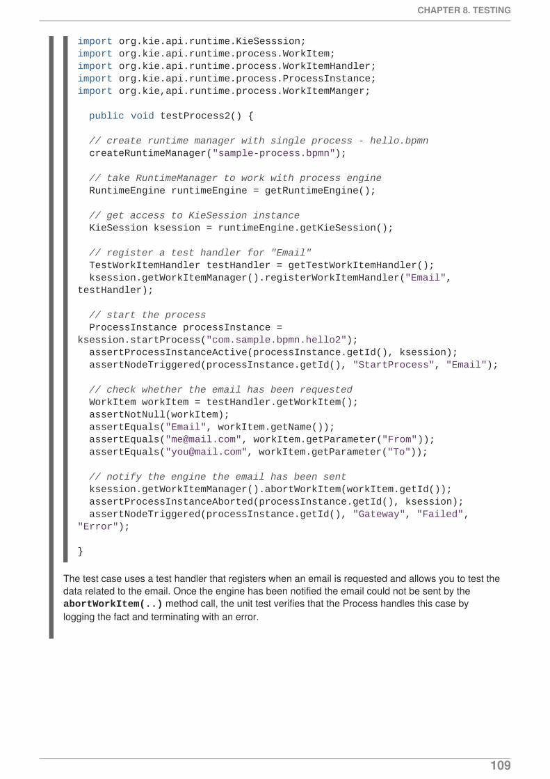
The test case uses a test handler that registers when an email is requested and allows you to test thedata related to the email. Once the engine has been notified the email could not be sent by the abortWorkItem(..) method call, the unit test verifies that the Process handles this case bylogging the fact and terminating with an error.
import org.kie.api.runtime.KieSesssion;import org.kie.api.runtime.process.WorkItem;import org.kie.api.runtime.process.WorkItemHandler;import org.kie.api.runtime.process.ProcessInstance;import org.kie,api.runtime.process.WorkItemManger;
public void testProcess2() {
// create runtime manager with single process - hello.bpmn createRuntimeManager("sample-process.bpmn");
// take RuntimeManager to work with process engine RuntimeEngine runtimeEngine = getRuntimeEngine();
// get access to KieSession instance KieSession ksession = runtimeEngine.getKieSession();
// register a test handler for "Email" TestWorkItemHandler testHandler = getTestWorkItemHandler(); ksession.getWorkItemManager().registerWorkItemHandler("Email", testHandler);
// start the process ProcessInstance processInstance = ksession.startProcess("com.sample.bpmn.hello2"); assertProcessInstanceActive(processInstance.getId(), ksession); assertNodeTriggered(processInstance.getId(), "StartProcess", "Email");
// check whether the email has been requested WorkItem workItem = testHandler.getWorkItem(); assertNotNull(workItem); assertEquals("Email", workItem.getName()); assertEquals("[email protected]", workItem.getParameter("From")); assertEquals("[email protected]", workItem.getParameter("To"));
// notify the engine the email has been sent ksession.getWorkItemManager().abortWorkItem(workItem.getId()); assertProcessInstanceAborted(processInstance.getId(), ksession); assertNodeTriggered(processInstance.getId(), "Gateway", "Failed", "Error");
}
CHAPTER 8. TESTING
109
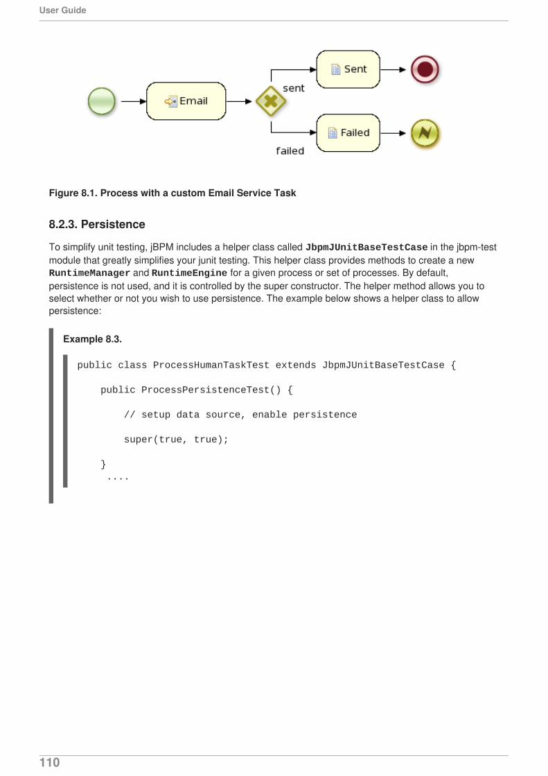
Figure 8.1. Process with a custom Email Service Task
8.2.3. Persistence
To simplify unit testing, jBPM includes a helper class called JbpmJUnitBaseTestCase in the jbpm-testmodule that greatly simplifies your junit testing. This helper class provides methods to create a new RuntimeManager and RuntimeEngine for a given process or set of processes. By default,persistence is not used, and it is controlled by the super constructor. The helper method allows you toselect whether or not you wish to use persistence. The example below shows a helper class to allowpersistence:
Example 8.3.
public class ProcessHumanTaskTest extends JbpmJUnitBaseTestCase {
public ProcessPersistenceTest() {
// setup data source, enable persistence
super(true, true);
} ....
User Guide
110

PART III. PLUG-IN
PART III. PLUG-IN
111
CHAPTER 9. PLUG-INRed Hat JBoss BPM Suite comes with a plug-in for Red Hat JBoss Developer Studio to provide supportfor the development of business processes in the Eclipse-based environment, such as debugging andtesting. It also provides a graphical Process Designer for business process editing.
Note that the repository structure follows the maven structure and is described in Chapter 3, Project.
For instructions on how to install and set up the plug-in refer to the Red Hat JBoss BPM Suite InstallationGuide.
9.1. CREATING BPM PROJECT
To create a BPM project, do the following:
1. On the main menu of JBoss Developer Studio, click File → New → jBPM project and then File→ New → Other.
2. Then choose jBPM → jBPM project.
3. In the New jBPM Project dialog, define the project name and location and click Next.
4. Select the required content of the project and click Next.
5. Select the runtime to be used by the project or click Configure Workspace Settings anddefine a new runtime (for details on runtime resources, refer to the Red Hat JBoss BPM SuiteInstallation Guide).
6. Select the required compatibility mode and click Finish.
The project with predefined maven structure and imported libraries is created in the defined workspacelocation and appears in navigation views (Package Explorer, Navigator).
NOTE
It is possible to create a Mavenized jBPM Project by selecting the following:
Click jBPM → jBPM Project (Maven)
9.2. CREATING PROCESS
In JBoss Developer Studio with the Red Hat JBoss BPM Suite plug-in, a Process is created the sameway as other resources:
1. Choose File → New → Other...
2. Select jBPM → BPMN2 Process.
3. In the displayed dialog box, define the location and the filename of the Process. Make sure youfollow maven structure requirements.
Once created, the Process is opened for editing in the graphical Process Designer.
User Guide
112
NOTE
Note that this Process may also be created with the following category:
Select BPMN2 → jBPM Process Diagram.
9.3. USING THE DEBUG PERSPECTIVE
In the Red Hat JBoss Developer Studio with Red Hat JBoss BPM Suite plug-in, you can make use of theextended debugging feature (debugging allows you to visualize and inspect the current state of runningprocess instances).
Note that breakpoints on Process elements are currently not supported. However, you can definebreakpoints inside any Java code in your Process; that is, your application code that is invoking theengine or invoked by the engine, listeners, etc. or inside rules that are evaluated in the context of aProcess.
Procedure 9.1. The Debug Perspective
1. Open the Process Instance view Window > Show View > Other ...
2. Select Process Instances and Process Instance under the Drools category
3. Use a Java breakpoint to stop your application at a specific point (for example, after starting anew process instance).
4. In the Debug perspective, select the ksession you would like to inspect.
5. The Process Instances view will show the process instances that are currently active inside thatksession.
6. When double-clicking a process instance, the process instance viewer will graphically show theprogress of that process instance.
7. Sometimes, when double-clicking a process instance, the process instance viewer complainsthat is cannot find the process. This means that the plug-in was not able to find the processdefinition of the selected process instance in the cache of parsed process definitions. To solvethis, simply change the process definition in question and save again.
The screenshot below illustrates the running process instance with an id of "1". This example processinstance relies on a human actor to perform "Task 1".
CHAPTER 9. PLUG-IN
113
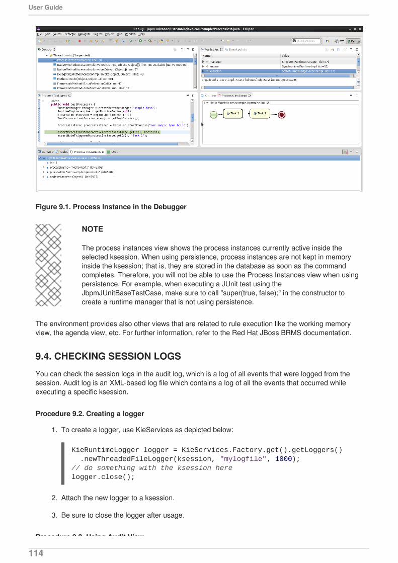
Figure 9.1. Process Instance in the Debugger
NOTE
The process instances view shows the process instances currently active inside theselected ksession. When using persistence, process instances are not kept in memoryinside the ksession; that is, they are stored in the database as soon as the commandcompletes. Therefore, you will not be able to use the Process Instances view when usingpersistence. For example, when executing a JUnit test using theJbpmJUnitBaseTestCase, make sure to call "super(true, false);" in the constructor tocreate a runtime manager that is not using persistence.
The environment provides also other views that are related to rule execution like the working memoryview, the agenda view, etc. For further information, refer to the Red Hat JBoss BRMS documentation.
9.4. CHECKING SESSION LOGS
You can check the session logs in the audit log, which is a log of all events that were logged from thesession. Audit log is an XML-based log file which contains a log of all the events that occurred whileexecuting a specific ksession.
Procedure 9.2. Creating a logger
1. To create a logger, use KieServices as depicted below:
2. Attach the new logger to a ksession.
3. Be sure to close the logger after usage.
Procedure 9.3. Using Audit View
KieRuntimeLogger logger = KieServices.Factory.get().getLoggers() .newThreadedFileLogger(ksession, "mylogfile", 1000);// do something with the ksession herelogger.close();
User Guide
114
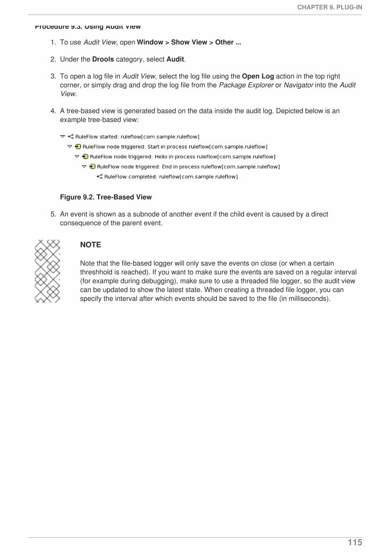
Procedure 9.3. Using Audit View
1. To use Audit View, open Window > Show View > Other ...
2. Under the Drools category, select Audit.
3. To open a log file in Audit View, select the log file using the Open Log action in the top rightcorner, or simply drag and drop the log file from the Package Explorer or Navigator into the AuditView.
4. A tree-based view is generated based on the data inside the audit log. Depicted below is anexample tree-based view:
Figure 9.2. Tree-Based View
5. An event is shown as a subnode of another event if the child event is caused by a directconsequence of the parent event.
NOTE
Note that the file-based logger will only save the events on close (or when a certainthreshhold is reached). If you want to make sure the events are saved on a regular interval(for example during debugging), make sure to use a threaded file logger, so the audit viewcan be updated to show the latest state. When creating a threaded file logger, you canspecify the interval after which events should be saved to the file (in milliseconds).
CHAPTER 9. PLUG-IN
115
PART IV. DEPLOYMENT AND RUNTIME MANAGEMENT
User Guide
116

CHAPTER 10. DEPLOYING PROJECTSOnce you have created a project with your Process definition and relevant resources, you need to build itand deploy it to the Process engine. Once deployed, you can create Process instances based on thedeployed resources.
To deploy your project from Business Central, do the following:
1. Open the Project Editor on your project (in Project Explorer navigate to your projectand in the top menu, click Tools → Project Editor).
2. You can define the Kie Base and Kie Session properties. If not, the default kbase and ksessionwill be used.
3. On the top menu, click the Build & Deploy button.
NOTE
From the 6.1 version of Red Hat JBoss BPM Suite, deployment units are stored inside thedatabase instead of the GIT repository. To override this behavior, set theorg.kie.git.deployments.enabled property to true.
10.1. PROCESS INSTANCES
Once you have modeled and deployed a Process definition along with all the resources it requires, youcan create its runtime instance, which will run on the Process engine.
From the Business Central you can further manage the instance during runtime, monitor its execution,and work with the Tasks the instance produces if having the proper roles assigned.
10.1.1. Instantiating a Process
To instantiate a deployed Process definition, do the following:
1. Display the Process Definitions view: on the top menu, click Process Management →Process Definitions.
2. Look up the Process Definition and in the respective row, click the Instantiate icon .
3. In the displayed dialog view, enter the properties and input paramaters for the Process instance.
10.1.2. Monitoring a Process instance
You can monitor the progress of a running Process instance from the Business Console:
1. On the top menu of the Business Central, go to Process Management → Process Instances.
2. In the list on the Process Instances tab, locate the required running Process instance and
click the Details button in the instance row.
CHAPTER 10. DEPLOYING PROJECTS
117
10.1.3. Aborting a Process instance
You can abort a running Process instance either using the provided API or from the ManagementConsole.
Aborting a Process instance using APITo abort a Process instance using the Kie Session API, use the void abortProcessInstance(long processInstanceId) call on the parent Kie Session.
Aborting a Process instance from the Management ConsoleTo abort a Process instance from the Management Console, do the following:
1. On the top menu of the Management Console, go to Process Management → ProcessInstances.
2. In the list on the Process Instances tab, locate the required Process instance and click the
Abort button in the instance row.
10.2. USER TASKS
A User Task represents a piece of work the given user can claim and perform. User Tasks can behandled within the Task client perspective of the Business Central: the view displays the Task List for thegiven user. You can think about it as a to-do item. The User Task appears in your list either because theUser Task element generated the User Task as part of Process execution or because someone hascreated the User Task directly in the Business Central console..
A User Task can be assigned to a particular actor, multiple actors, or to a group of actors. If assigned tomultiple actors or a group of actors, it is visible in the Task Lists of all the actors and any of the possibleactors can claim the task and execute it. The moment the Task is claimed by one actor, it disappearsfrom the Task List of other actors.
Task clientUser Tasks are displayed in the Tasks perspective, that are an implementation of a Task client, in theBusiness Central console: to display the Tasks perspective, click Tasks → Tasks List. The perspectiveprovides multiple Task views: to switch between the views, click the respective button in the menu bar ofthe Tasks List view (Grid or Calendar). The Calendar view provides the Task list in Day, Week,or Month layouts. You can filter out the Tasks based on their status using the buttons Active,
Personal, Group, and All in the view toolbar.
Note that group Tasks are marked with the group icon and you can claim them by clicking the Claim
button. To undo the claim process, click the button again.
The Task details are available in the panel that appears after clicking the Details icon in the Actions
column : the panel contains the Work, Assignments, Details, and Comments button: On theComments button, you can review comments provided by other users on the Task and add your owncomments. To work on the Task, open the Work tab: the respective Form defined for the Task appears (ifthe current user hasn't been assigned the task, a form to claim the task appears first)). If no Form for theTask is defined a default Form is generated based on the jbpm-playground.git/globals/forms/DefaultTask.ftl file and on the input and output data of theTask.
User Guide
118
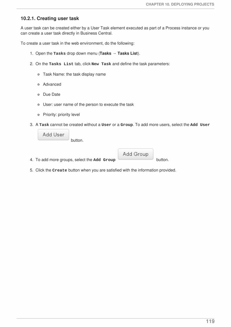
10.2.1. Creating user task
A user task can be created either by a User Task element executed as part of a Process instance or youcan create a user task directly in Business Central.
To create a user task in the web environment, do the following:
1. Open the Tasks drop down menu (Tasks → Tasks List).
2. On the Tasks List tab, click New Task and define the task parameters:
Task Name: the task display name
Advanced
Due Date
User: user name of the person to execute the task
Priority: priority level
3. A Task cannot be created without a User or a Group. To add more users, select the Add User
button.
4. To add more groups, select the Add Group button.
5. Click the Create button when you are satisfied with the information provided.
CHAPTER 10. DEPLOYING PROJECTS
119
CHAPTER 11. LOGGINGLogs with execution information are created based on events generated by the process engine duringexecution. It is the engine providing a generic mechanism listening to events. Information about thecaught event can be extracted from these logs and then persisted in a data storage. To restrain thelogged information, the log filtering mechanism is provided (for further information, refer to the Red HatJBoss BPM Suite Administration and Configuration Guide).
User Guide
120
CHAPTER 12. EXAMPLESRed Hat JBoss BPM Suite comes with a project with assets examples to demostrate the possible usageand capabilities of the product.
Also, the project contains Junit tests for each Element, which are simple working examples. These testprocesses can serve as simple examples. The entire list can be found in the src/test/resources folder forthe jbpm-bpmn2 module. Note that each of the processes is accompanied by a junit test that tests theimplementation of the construct.
CHAPTER 12. EXAMPLES
121

PART V. BAM
User Guide
122
CHAPTER 13. RED HAT JBOSS DASHBOARD BUILDERRed Hat JBoss Dashboard Builder is a web-based dashboard application that provides Business ActivityMonitoring (BAM) support, that is, visualization tools for monitored metrics (Key Performance Indicators,or KPIs) in real time. It comes integrated in the Business Central environment under the Dashboardsmenu.
It comes with a dashboard that requests information from the Red Hat JBoss BPM Suite ExecutionEngine and provides real-time information on its runtime data; however, you can create also customdashboards over other data resources, which leaves the application relatively standalone.
WHAT IS BUSINESS ACTIVITY MONITORING?Business Activity Monitoring (BAM) software helps to monitor business activities that take place on acomputer system in real time. The software monitors particular metrics, such as, the status of runningprocesses, the number of invoices to be processed, processing times, etc. It provides tools forvisualization of the collected data in graphs, tables, etc.
13.1. ACCESSING DASHBOARD BUILDER
Dashboard Builder is accessible in both business-central and as a standalone applications.
Within business-central, the Dashboard Builder is accessed directly from the Dashboards menu, and itintegrates the jBPM Dashboard workspace that is accessible using Dashboards > Process & TaskDashboards menus.
Process & Task Dashboards displays a pre-defined dashboard based on runtime data fromthe Execution Server. In the menu on the left, select the entity you are interested. The widgets onthe right will display the data for the entity.
As a standalone application, Dashboard Builder can be accessed in one of the following ways:
Using the URL https://HOSTNAME/dashbuilder (with the appropriate Hostname).
Using business-central with Dashboards > Business Dashboard menus.
Business Dashboards displays the environment in which you can create your owndashboards. Procedures on how to create a custom dashboard are provided below.
13.2. BASIC CONCEPTS
The Dashboard Builder can establish connections to external data sources such as databases. Theseconnections are then used for creating data providers that obtain data from the data sources. TheDashboard Builder is connected to the local JBoss BPM Suite engine by default and acquires from it thedata for its JBoss BPM Suite Dashboard indicators (widgets with visualizations of the data available onthe pages of the JBoss BPM Suite Dashboard workspace).
If operating over a database, the data provider uses an SQL query to obtain the data and if operatingover a CSV file, the data provider automatically obtains all the data from the file. So it is the dataproviders that keep the data you work with.
Data from the data providers can then be visualized in indicators, special panels, on pages as graphs ortables. Pages are contained within a workspace and can define permission access rights. The number ofpages within a workspace is arbitrary. A set of pages that present related information on similar KPIs isrefered to as a dashboard.
CHAPTER 13. RED HAT JBOSS DASHBOARD BUILDER
123
13.3. ENVIRONMENT
There are two ways to access the Dashbuilder environment: through business-central and your localhost.
Procedure 13.1. To access Dashbuilder through business-central
1. Log into business-central with your user account.
2. Select Dashboard > Business Dashboard.
3. Dashbuilder will open in a new browser / window tab.
Procedure 13.2. To access Dashbuilder through web browser.
1. Go to Dashbuilder directly through https://HOSTNAME/dashbuilder
2. An example instance running the local host would be https://localhost:8080/dashbuilder
After you log in, you are redirected to the Showcase workspace with the welcome page displayed.
On the top is the menu panel with the options on workspaces and pages, and logout and generalconfiguration buttons. This part is common for all workspaces.
Below is the dashboard area with variable content. It consists of the sidebar or lateral menu on the leftand the main dashboard area on the right.
13.4. DATA SOURCES
Red Hat JBoss Dashboard Builder can be connected to an external database, be it using JNDI of thecontainer or connecting directly only using the JDBC driver to access the database. Connections todatabases can be configured in workspace Showcase on page External Connections. After you haveestablished the connection to the database, you need to create a data provider that will collect the datafrom the database and allow you to visualize it as an indicator in the dashboard area of a page.
When connecting to CSV files to acquire data, the connection is estabished directly through the dataprovider.
Note that Red Hat JBoss Dashboard Builder makes use of its own local internal database to store itslocal data. This database is read-only for Dashboard Builder, but is accessible from outside.
13.4.1. Connecting to data sources
You can connect either to a JNDI data source, that is, a data source set up and accessible from theapplication container, or directly to the data source as a custom data source, if the application containerhas the correct JDBC driver deployed.
To connect to an external data source, do the following:
1. Make sure the data source is up and running and that the application server has access to thedata source. (Check the driver, the login credentials, etc. In Red Hat JBoss EAP 6, you can doso in the Management Console under Subsystems → Connector → Datasources)
2. In Dashboard Builder, on the Tree Menu (by default located on the of the Showcaseperspective), go to Administration → External connections.
User Guide
124
3. On the displayed External Connection panel, click the New DataSource
button.
4. Select the data source type (JNDI or Custom DataSource) and provide the respective datasource parameters below.
If you wish the jBPM Dashboard to use the new data source, modify also the respective data providers(jBPM Count Processes, jBPM Process Summary, jBPM Task Summary). Note that the data sourceneeds to have access to jBPM history.
13.4.2. Security considerations
IMPORTANT
When creating an external datasource using JBoss Dashboard Builder, it needs to use thelocal connection so that the user can be passed through. Otherwise, with a connectionthat uses <host>:<port>, every user would have the same virtual database (VDB)permissions.
13.4.3. Building a Dashboard for Large Volumes of Data
You can connect Red Hat JBoss Dashboard Builder to external databases and load data for generatingreports and charts. Generally, if the volume of data is small (up to 2MB), Red Hat JBoss DashboardBuilder preloads the data into (local) memory and uses this data for report and chart generation.However, in case of large volumes of data, it is not possible to load the entire data set into theDashboard Builder's local memory.
Based on the volume of data you are dealing with, you can choose to query the database to build adashboard report in any one of the following strategies:
The in-memory strategy
The in-memory strategy is to create a data provider that loads all the required data from thedatabase by executing a single SQL query on the relevant tables, into the Dashboard Builder'smemory. In this case, every indicator on the Dashboard Builder shares the same data set. Whenyou use filters from the Dashboard Builder user interface to access specific data from this dataset, the Dashboard Builder fetches the data from the internal memory and does not executeanother SQL query again on the database. This strategy has a simple data retrieval logic as itdeals with creating a single data provider. As all the data set properties are available to you atonce, it allows you to configure KPIs faster. However, this approach is not suitable for large datasets as it would lead to poor performance.
The native strategy
The native approach is to create a data provider for every indicator in the Dashboard Builder anddoes not require loading all the data into the internal memory at once. So each time you use afilter from the Dashboard Builder user interface, the corresponding SQL queries get executedand fetches the required data from the database. So there is no data in the Dashboard Builder'sinternal memory. This strategy works best in case of large volumes of data, however it needsproper indexing on the database tables. Also, setting up data providers for multiple KPIs iscomplicated as compared to creating a single data provider in case of in-memory strategy.
Example
CHAPTER 13. RED HAT JBOSS DASHBOARD BUILDER
125
Let us consider a case when you want to create a stock exchange dashboard comprising the followingcharts and reports:
Bar chart for Average price per company
Area chart for Sales price evolution
Pie chart for Companies per country
Table report for Stock prices at closing date
For these charts and reports, let us assume that the Dashboard Builder accesses data from the followingtables:
Company: Comprising columns ID, NAME, and COUNTRY.
Stock: Comprising columns ID, ID_COMPANY, PRICE_PER_SHARE, and CLOSING_DATE.
For the in-memory strategy of building a dashboard, the following SQL query fetches all the required datafrom these two tables:
The output of this query is saved in the Dashboard Builder's local memory. The Dashboard accessesthis data every time a filter is run.
On the other hand, if you are using the native strategy for huge volumes of data , an SQL query isexecuted on every filter request made by the Dashboard Builder and corresponding data is fetched fromthe database. In this case here is how each filter accesses the database:
For the bar chart on Average price per company, the following SQL query is executed:
For the area chart on Sales price evolution, the following SQL query is executed:
For the pie chart on Companies per country, the following SQL query is executed:
SELECT C.NAME, C.COUNTRY, S.PRICE_PER_SHARE, S.CLOSING_DATE FROM COMPANY C JOIN STOCK S ON (C.ID=S.ID_COMPANY)
SELECT C.NAME, AVG(S.PRICE_PER_SHARE) FROM COMPANY C JOIN STOCK S ON (C.ID=S.ID_COMPANY) WHERE {sql_condition, optional, c.country, country} AND {sql_condition, optional, c.name, name} GROUP BY C.NAME
SELECT S.CLOSING_DATE, AVG(S.PRICE_PER_SHARE) FROM COMPANY C JOIN STOCK S ON (C.ID=S.ID_COMPANY) WHERE {sql_condition, optional, c.country, country} AND {sql_condition, optional, c.name, name} GROUP BY CLOSING_DATE
SELECT COUNTRY, COUNT(ID) FROM COMPANY WHERE {sql_condition, optional, country, country} AND {sql_condition, optional, name, name} GROUP BY COUNTRY
User Guide
126
For the table report on Stock prices at closing date, the following SQL query is executed:
For each of these queries, you need to create a separate SQL data provider.
In the examples above, each KPI delegates the filter and group by operations to the database throughthe {sql_condition} clauses. The signature of the {sql_condition} clause is the following:
Here,
optional: This indicates that if there is no filter for the given property, then the condition isignored.
required: This indicates that if there is no filter for the given property, then the SQL returns nodata.
db column: This indicates the database column where the current filter is applied.
filter property: This indicates the selected UI filter property.
When a filter occurs in the UI, the Dashboard Builder parses and injects all the SQL data providersreferenced by the KPIs into these SQL statements. Every time a filter occurs in the UI, the DashboardBuilder gets all the SQL data providers referenced by the KPIs and injects the current filter selectionsmade by the user into these SQLs.
13.4.4. Data providers
Data providers are entities that are configured to connect to a data source (a CSV file or database),collect the required data, and assign them the data type. You can think about them as database queries.
The collected data can be then visualized in indicators on pages, exported as XLS or CSV, etc.
13.4.4.1. Creating data providers
To create a new data provider, do the following:
1. In the Tree Menu (the panel in the lateral menu of the Showcase workspace), clickAdministration → Data providers.
2. In the Data Providers panel, click the Create new data provider
button.
3. In the updated Data Providers panel, select in the Type dropdown menu the type of the dataprovider depending on the source you want the data provider to operate on.
4. Define the data provider parameters:
Data provider over a CSV file
SELECT C.NAME, C.COUNTRY, S.PRICE_PER_SHARE, S.CLOSING_DATE FROM COMPANY C JOIN STOCK S ON (C.ID=S.ID_COMPANY) WHERE {sql_condition, optional, c.country, country} AND {sql_condition, optional, c.name, name}
{sql_condition, [optional | required], [db column], [filter property]}
CHAPTER 13. RED HAT JBOSS DASHBOARD BUILDER
127
Name: user-friendly name and its locale
CSV file URL: the url of the file (for example, file:///home/me/example.csv)
Data separator: the symbol used as separator in the CSV file (the default value issemicolon; if using comma as the separator sign, make sure to adapt the number formatif applicable)
Quoting symbol: the symbol used for quotes (the default value is the double-quotessymbol; note that the symbol may vary depending on the locale)
Escaping symbol: the symbol used for escaping the following symbol in order to keep itsliteral value
Date format: date and time format
Number format: the format of numbers as resolved to thousands and decimals
Data provider over a database (SQL query)
Name: user-friendly name and its locale
Data source: the data source to query (the default value is local, which allows you toquery the Dashboard Builder database)
Query: query that returns the required data
5. Click Attempt data load to verify the parameters arecorrect.
6. Click Save.
7. In the table with the detected data, define the data type and if necessary provide a user-friendlyname for the data. Click Save.
The data provider can now be visualized in an indicator on a page of your choice.
13.4.5. Workspace
A workspace is a container for pages with panels or indicators.
By default, the Showcase and jBPM Dashboard workspaces are available.
To switch between workspaces, select the required workspace in the Workspace dropdown box in thetop panel on the left. To create a new workspace, click the Create workspace icon ( ) in the top
menu on the left. You can also edit the current workspace properties, delete the current workspace, andduplicate the current workspace using icons in the top panel.
Every workspace uses a particular skin and envelope, which define the workspace's graphicalproperties.
13.4.5.1. Creating a workspace
To create a new workspace, do the following:
User Guide
128
1. Click the Create workspace button on the top menu.
The management console with the Workspace node expanded and workspace managementarea with workspace details on the right is displayed.
2. In the Create workspace table on the right, set the workspace parameters:
Name: workspace name and its locale
Title: workspace title and its locale
Skin: skin to be applied on the workspace resources
Envelope: envelope to be applied on the workspace resources
3. Click Create workspace.
4. Optionally, click the workspace name in the tree menu on the left and in the area withworkspace properties on the right define additional workspace parameters:
URL: the workspace URL
User home search: the home page setting
If set to Role assigned page, the home page as as in the page permissions is applied;that is, every role can have a different page displayed as its home page. If set to Current page, all users will use the current home page as their home page.
13.4.5.2. Pages
Pages are units that live in a workspace and provide space (dashboard) for panels. By default, you candisplay a page by selecting it in the Page dropdown menu in the top panel.
Every page is divided in two main parts: the lateral menu and the central part of the page. The parts aredivided further (the exact division is visible when placing a new panel on a page). Note that the lateralmenu allows you to insert panels only below each other, while in the central part of the page you caninsert panels below each other as well as tab them.
A page also has a customizable header part and logo area.
13.4.5.2.1. Creating Pages
To create a new page, do the following:
1. Make sure you are in the correct workspace.
2. Next to the Page dropdown box in the top menu, click
the Create new page button .
3. The management console with the Pages node expanded and page management area withpage details on the right is displayed.
4. In the Create new page table on the right, set the page parameters:
Name: page name and its locale
CHAPTER 13. RED HAT JBOSS DASHBOARD BUILDER
129
Parent page: parent page of the new page
Skin: skin to be applied on the page
Envelope: envelope to be applied on the page
Page layout: layout of the page
5. Click Create new page.
6. Optionally, click the page name in the tree menu on the left and in the area with workspaceproperties on the right define additional page parameters:
URL: the page URL
Visible page: visibility of the page
Spacing between regions and panels
13.4.5.2.2. Defining Page permissions
Although users are usually authorized using the authorization method setup for the underlyingapplication container (on Red Hat JBoss EAP, the other security domain by default), the Red HatJBoss Dashboard Builder has its own role-based access control (RBAC) management tool to facilitatepermission management on an individual page or multiple pages.
To define permissions on a page or all workspace pages for a role, do the following:
1. On the top menu, click the General configuration button : the management consoleis displayed.
2. Under the Workspace node on the left, locate the page or the Pages node.
3. Under the page/pages node, click the Page permissions node.
4. In the Page permissions area on the right, delete previously defined permission definition ifapplicable and define the rights for the required role:
a. In the Permission assignation table, locate the Select role dropdown menu andpick the respective role.
b. In the Actions column of the table, enable or disable individual permissions.
5. Click Save.
13.4.5.3. Panels
A panel is a GUI widget, which can be placed on a page. There are three main types of panels:
Dashboard panels
are the primary BAM panels and include the following:
Data provider manager: a panel with a list of available data providers and data providermanagement options
User Guide
130
Filter and Drill-down: a panel that displays all KPIs and their values to facilitate filtering inindicators on the given page defined over a data provider
HTML Editor panel: a panel with static content
Key Performance Indicator (indicator): a panel that visualizes the data of a data provider
Navigation panels
are panels that provide navigation functions and include the following:
Breadcrumb: a panel with the full page hierarchy pointing to the current page
Language menu: a panel with available locales (by default in the top center)
Logout panel: a panel with the name of the currently logged-in user and the logout button
Page menu custom: a panel with vertically arranged links to all pages in the workspace (thelist of pages can be adjusted) and general controls for the HTML source of the page
Page menu vertical: a panel with vertically arranged links to all pages in the workspace (thelist of pages can be adjusted)
Page menu horizontal: a panel with horizontally arranged links to all pages in the workspace(the list of pages can be adjusted)
Tree menu: a panel with the links to essential features such as Administration, Home (on theHome page of the Showcase workspace displayed on the left, in the lateral menu)
Workspace menu custom: a panel with links to available workspaces (the list of workspacescan be adjusted) and general controls for the HTML source of the workspace
Workspace menu horizontal: a horizontal panel with links to available workspaces (the list ofworkspaces can be adjusted)
Workspace menu vertical: a vertical panel with links to available workspaces (the list ofworkspaces can be adjusted)
System panels
are panels that provide access to system setting and administration facilities and include the following:
Data source manager: a panel for management of external data sources
Export dashboards: a panel export of dashboards
Export/Import workspaces: a panel for exporting and importing of workspaces
13.4.5.3.1. Adding panels
To add an existing panel to a page or to create a new panel, do the following:
1. Make sure the respective page is open (in the Page dropdown menu of the top menu select thepage).
2. In the top menu, click the Create a new panel in current page button.
CHAPTER 13. RED HAT JBOSS DASHBOARD BUILDER
131

3. In the displayed dialog box, expand the panel type you want to add (Dashboard, Navigation,or System) and click the panel you wish to add.
4. From the Components menu on the left, drag and drop the name of an existing panel instanceor the Create panel item into the required location on the page.
If inserting a new indicator, the Panel view with the graph settings will appear. Define the graphdetails and close the dialog.
If adding an instance of an already existing indicator, you might not be able to use it, if it is linkedto the KPIs on the particular original page. In such a case, create a new panel.
5. If applicable, edit the content of the newly added panel.
User Guide
132
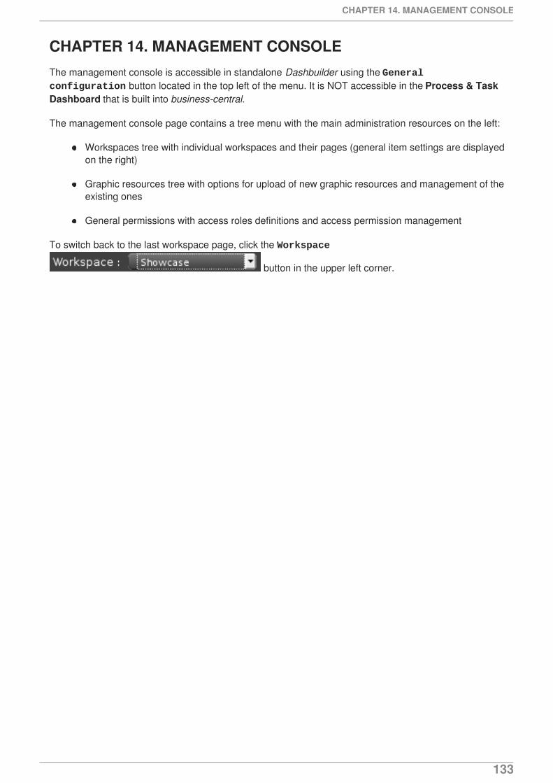
CHAPTER 14. MANAGEMENT CONSOLEThe management console is accessible in standalone Dashbuilder using the General configuration button located in the top left of the menu. It is NOT accessible in the Process & TaskDashboard that is built into business-central.
The management console page contains a tree menu with the main administration resources on the left:
Workspaces tree with individual workspaces and their pages (general item settings are displayedon the right)
Graphic resources tree with options for upload of new graphic resources and management of theexisting ones
General permissions with access roles definitions and access permission management
To switch back to the last workspace page, click the Workspace
button in the upper left corner.
CHAPTER 14. MANAGEMENT CONSOLE
133
CHAPTER 15. GRAPHIC RESOURCESRed Hat JBoss Dashboard Builder uses the following components to define the environment appearanceand thus divide the representation resources from content and data:
Skins define a set of style sheets, images, and icons
Region layouts define layouts of regions for pages
Envelopes define an HTML template used as page frames
GRAPHIC RESOURCES DEFINITIONSAll graphics components are deployed as zip files as part of the Red Hat JBoss Dashboard Builder in the$DEPLOYMENT_LOCATION/dashbuilder.war/WEB-INF/etc/ directory.
Every component definition contains the following:
properties file that defines the name of the component for individual supported locales, the nameof the css file to be applied on the component, and mapping of file to individual componentelements
JSP, HTML, CSS files, and image and icon resources referenced from the properties file
When creating custom graphic resources, it is recommended to download one of the existingcomponents and modify it as necessary. This will prevent unneccessary mistakes in your definition.
15.1. WORKING WITH GRAPHIC RESOURCES
1. On the top menu, click the General configuration button .
2. Under the Graphic resources node on the left, click the component type you want to workwith (Skins, Layouts, Envelopers). The window on the right will display the content relevantfor the given component type.
3. On the right, you can now do the following:
Upload a new component: you need to provide a unique ID for the component and theresource zip file. Then click Add.
Download a component definition or preview the component: in the table below the Addview, click the respective icon in the Actions column.
User Guide
134
APPENDIX A. PROCESS ELEMENTSA Process Element is a node of the Process definition. The term covers the nodes with executionsemantics as well as those without.
A.1. PROCESS
A Process is a named element defined in a Process Definition. It exists in a Knowledge Base and isidentified by its ID.
A Process represents a namespace and serves as a container for a set of modeling elements: it containselements that specify the execution workflow of a Business Process or its part using Flow objects andFlows. Every Process must contain at least one Start Event and one End Event.
A Process is accompanied by its BPMN Diagram, which is also part of the Process Definition and defineshow the Process execution workflow is depicted when visualized, for example in the Process Designer.
Apart from the execution workflow and Process attributes, a Process can define Process variables,which store Process data during runtime. For more information on Process variables, refer toSection 4.8, “Variables”.
RuntimeDuring runtime, a Process serves as a blueprint for a Process instance (the concept of class and itsobject in OOP). A Process instance lives in a Session that may contain multiple Process instances. Thisallows the instances to share data, for example, using Globals that live in the Session instance, not in theProcess instance. Every Process instance has its own context and ID.
Knowledge Runtime, called kcontext, holds all the Process runtime data. You can call it in your code,for example, in Action scripts, to obtain or modify the runtime data:
Getting the currently executed Element instance so as to query further Element data, such as itsname and type, or cancel the Element instance.
Example A.1. Getting the currently executed Element
Getting the currently executed Process instance so as to query further Process instance data,such as, its name, ID, or abort or send an event, such as a Signal.
Example A.2. Getting the currently executed Process and sending it a Signal event
Getting and setting the values of variables
Execute calls on the Knowledge runtime, for example, start Process instances, insert data, etc.
A Process instance goes through the following life cycle:
NodeInstance element = kcontext.getNodeInstance();String name = element.getNodeName();
ProcessInstance proc = kcontext.getProcessInstance();proc.signalEvent( type, eventObject );
APPENDIX A. PROCESS ELEMENTS
135
1. The createProcessInstance method is called on a Process: a new process instance basedon a Process is created and Process variables are initialized . The process instance is in status CREATED.
2. The start() method is called on the ProcessInstance: the execution of the Process instance istriggered (the token on the Start Event is generated). If the Process was instantiated manually,the token is generated only on its None Start Event. If it is instantiated using another mechanism,such as Signal, Message, or Error, the token is generated on the Start Event of the respectivetype that is defined to handle the particular object. The process instance becomes ACTIVE.
3. Once there is no token in the flow (tokens are consumed by End Events and destroyed byTerminating Events), the Process instance is finished and becomes CANCELLED.
The runtime state of a Process instance can be made persistent, for example, in a database. This allowsto restore the state of execution in case of environment failure, or to temporarily remove runninginstances from memory and restore them later. By default, process instances are not made persistent.For more information on persistence refer to the Administration and Configuration Guide for JBoss BPMSuite.
Properties
ID
Process ID defined as a String unique in the parent Knowledge Base
Example value: org.jboss.exampleProcess
It is recommended to use the ID form <packageName>.<processName>.<version>.
Name
Process display name
Version
Process version
Package
Parent package the Process belongs to (Process namespace)
Possible values: true, false
Target Namespace
BPMN2 xsd location
Executable
type of the process as concerns its executability
Possible values: true, false
Imports
Imported Process
Documentation
User Guide
136
Documentation is a generic element attribute that can contain element description. It has no impacton runtime.
AdHoc
Boolean property defining whether a Process is an Ad-hoc Process:
If set to true, the flow of the Process execution is controlled exclusively by a human user.
Executable
Boolean property defining whether a Process is intended for execution or not (if set to false, theprocess cannot be instantiated)
Globals
Set of global variables visible for other Processes to allow sharing of data between them
A.2. EVENTS MECHANISM
During process execution, the Process Engine makes sure that all the relevant tasks are executedaccording to the Process definition, the underlying work items, and other resources. However, a Processinstance often needs to react to a particular event it was not directly requesting. Such events can becreated and caught by the Intermadiate Event elements (refer to the User Guide). Explicitly representingthese events in a Process allows the author to specify how the particular Event should be handled.
An Event must specify the type of event it should handle. It can also define the name of a variable, whichwill store the data associated with the event. This allows subsequent elements in the Process to accessthe event data and take appropriate action based on this data.
An event can be signaled to a running instance of a process in a number of ways:
Internal event: Any action inside a process (for example, the action of an action node, or an on-entry or on-exit action of some node) can signal the occurrence of an internal event to thesurrounding Process instance.
Example A.3. Schema of the call sending an event to the Process instance
External event: A process instance can be notified of an event from outside
Example A.4. Schema of the call notifying a Process instance about an external event
External event using event correlation: Instead of notifying a Process instance directly, you cannotify the entire Session and let the engine determine which Process instances might beinterested in the event using event correlation. Event correlation is determined based on theevent type. A Process instance that contains an Event element listening to external events ofsome type is notified whenever such an event occurs. To signal such an event to the processengine, write code such as:
Example A.5. Schema of the call notifying a Session about an external event
kcontext.getProcessInstance().signalEvent(type, eventData);
processInstance.signalEvent(type, eventData);
APPENDIX A. PROCESS ELEMENTS
137
Events can also be used to start a process. Whenever a Message Start Event defines an event trigger ofa specific type, a new process instance starts every time that type of event is signalled to the processengine.
This mechanism is used for implementation of the Intermdetiate Events and can be used to definecustom Events if necessary.
A.3. COLLABORATION MECHANISMS
Elements with execution semantics make use of general collaboration mechanisms. Different Elementsallow you to access and use the mechanism in a different way; for example, there is a mechanism calledsignalling: a Signal is sent by a Throw Signal Intermediate Event Element and received by a CatchSignal Intermediate Event (two Elements with execution semantics make use of the same Signalmechanism).
Collaboration mechanism includes the following:
Messages: Messages are used to communicate within the process and between processinstances. Messages are implemented as signals which makes them scoped only for a given KSession instance.
For external system interaction send and receive task should be used with proper handlerimplementation.
Escalations: mainly inter-process (between processes) signalling of escalation to triggerescalation handling
Errors: mainly inter-process signalling of escalation to trigger escalation handling
Signals: general, mainly inter-process instance communication
All the events are managed by the signaling mechanism. To distinguish individual objects of individualmechanism the signal use different signal codes or names.
A.3.1. Messages
“A Message represents the content of a communication between two Participants. In BPMN 2.0, aMessage is a graphical decorator (it was a supporting element in BPMN 1.2). An ItemDefinition is usedto specify the Message structure.[1]”
Messages are objects that can be sent between Processes or Process elements, that participate in therespective communication; They are sent by the Message Intermediate Throw Events and Send Tasks,and can be consumed by the Message Start Events, Message Intermediate Catch Events, MessageEnd Events, and Receive Tasks. One Message can be consumed by an arbitrary number of Processesand Process elements.
Attributes
Mandatory Attributes
Message
ksession.signalEvent(type, eventData);
User Guide
138
string with the message
A.3.2. Escalation
"An Escalation identifies a business situation that a Process might need to react to." [2]
The Escalation mechanism is intended for the handling of events that need the attention of someone ofhigher rank, or require additional handling.
Escalation is represented by an Escalation object that is propagated across the Process instances. It isproduced by the Escalation Intermediate Throw Event or Escalation End Event, and can be consumedby exactly one Escalation Start Event or Escalation Intermediate Catch Event. Once produced, it ispropagated within the current context and then further up the contexts until caught by an Escalation StartEvent or Escalation Intermediate Catch Event, which is waiting for an Escalation with the particularEscalation Code. If an Escalation remains uncaught, the Process instance is ABORTED.
Attributes
Mandatory Attributes
Escalation Code
string with the escalation code
A.3.3. Signals
A Signal is an object, which can be propagated on execution within its parent Process instance as wellas to other Processes. Every Signal can be consumed by multiple elements in multiple Process instancewithin the same Session.
Every Signal defines its Signal Reference, which is unique in the respective Session. A Signal can begenerated by a Throw Signal Event and an action of an Activity. Once generated, it is propagated as anobject through all the context in the parent Session of the Signal element.
NOTE
To trigger a Signal using API, you can use in your code the following:
To instantiate a Process instance directly with a Signal, you can use the followingAPI function:
The eventType parameter defines the Signal's Event Type, the data parameterdefines the data accompanying the Signal, and processInstanceId defines the IDof the Process to be instantiated.
To trigger a Signal from a script, that is, from a Script Task or using on-entry oron-exit actions of a node, you can use the following API function:
ksession.signalEvent(eventType, data, processInstanceId)
kcontext.getKieRuntime().signalEvent( eventType, data, kcontext.getProcessInstance().getId());
APPENDIX A. PROCESS ELEMENTS
139
A.4. TRANSACTION MECHANISMS
A.4.1. Errors
An Error represents a critical problem in a Process execution and is indicated by the Error End Event.When a Process finishes with an Error End Event, the event produces an Error object with a particularError Code that identifies the particular error end that occurred. The Error End Event represents anunsuccessful execution of the given Process or Activity. Once generated, it is propagated as an objectwithin the current context and then further up the contexts until caught by the respective catching ErrorIntermediate Event or Error Start Event, which is waiting for an Error with the particular Error Code. If theError is not caught and is propagated to the upper-most Process context, the Process instance becomesABORTED.
Every Error defines its Error Code, which is unique in the respective Process.
Attributes
Error Code
Error Code defined as a String unique within the Process.
A.4.2. Compensation
Compensation is a mechanism that allows you to handle business exceptions that might occur in aProcess or Sub-Process (Business transactions), that is to compensate for a failed transaction, wherethe transaction is presented by the Process or Sub-Process, and then continues the execution using theregular Flow path. Note, that compensation is triggered only after the execution of the transaction hasfinished and that either with a Compensation End Event or with a Cancel End Event.
NOTE
Consider implementing handling of business exceptions in the following cases:
When an interaction with an external party or 3rd party system may fail or befaulty
When you can not fully check the input data received by your Process (forexample, a client's address information)
When there are parts of your Process that are particularly dependent on one ofthe following:
Company policy or policy governing certain in-house procedures
Laws governing the business process (such as, age requirements)
If a business transaction finishes with a Compensation End Event, the Event produces a "request" forcompensation handling. The compensation request is identified by ID and can be consumed only by therespective Compensation Intermediate Event placed on the boundary of the transaction Elements andCompensation Start Event. The Compensation Intermediate Event is connected with an AssociationFlow to the Activity that defines the compensation, such as a Sub-Process or Task. The execution floweither waits for the compensation activity to finish or resumes depending on the Wait for completionproperty set on the Compensation End Event of the business transaction that is being compensated.
User Guide
140
If a business transaction contains an Event Sub-Process that starts with a Compensation Start Event, theEvent Sub-Process is run as well if compensation is triggered.
The Activity the Compensation Intermediate Event points to, might be a Sub-Process. Note that the Sub-Process must start with the Compensation Start Event.
If running over a multi-instance Sub-Process, compensation mechanism of individual instances do notinfluence each other.
A.5. TIMING
Timing is a mechanism for scheduling actions and is used by Timer Intermediate and Timer Start events.It allows you to delay further execution of a process or task.
NOTE
A timer event can be triggered only after the transaction commits, while the timercountdown starts right after entering the node (the attached node in case of a boundaryevent). In other words, a timer event is only designed for those use cases where there is await state, such as a "User Task". If you want to be notified of the timeout of asynchronous operation without a wait state, a boundary timer event is not suitable.
The timing strategy is defined by the following timer properties:
Time Duration
defines the period for which the execution of the event is put on hold. The execution continues afterthe defined period has elapsed. The timer is applied only once.
Time Cycle
This defines the time between subsequent timer activations. If the period is 0, the timer is triggeredonly once.
The value for these properties can be provided as either Cron or as an expression by defining the, TimeCycle Language property.
Cron
[#d][#h][#m][#s][#[ms]]
Example A.6. Timer period with literal values
The element will be executed after 1 day, 2 hours, 3 minutes, 4 seconds, and 5 milliseconds.
Any valid ISO8601 date format that supports both one shot timers and repeatable timers can beused. Timers can be defined as date and time representation, time duration or repeating intervals.For example:
Date
2013-12-24T20:00:00.000+02:00 - fires exactly at Christmas Eve at 8PM
Duration
1d 2h 3m 4s 5ms
APPENDIX A. PROCESS ELEMENTS
141
PT2S - fires 1 after 2 seconds
Repetable Intervals
R/PT1S - fires every second, no limit, alternatively R5/PT1S will fire 5 times every second
None
#{expression}
Example A.7. Timer period with expression
The element will be executed after time period returned by the call myVariable.getValue().
A.6. PROCESS ELEMENTS
IMPORTANT
This chapter contains introduction to BPMN elements and their semantics. By no meansdoes it aspire to be an exhaustive language specification. For details about BPMN referto Business Process Model and Notation, Version 2.0: The BPMN 2.0 specification is anOMG specification that defines standards on how to graphically represent a businessprocess, defines execution semantics for the elements along with an XML format ofprocess definitions source.
The specification also includes details on choreographies and collaboration. Note that RedHat JBoss BPM Suite focuses exclusive on executable processes and supports asignificant subset of the BPMN elements including the most common types that can beused inside executable processes.
A Process Element is a node of the Process definition. The term covers the nodes with executionsemantics as well as those without. Elements with execution semantics define the execution workflow ofthe Process, while Elements without execution semantics (Artifacts) allow users to provide notes andfurther information on the Process or any of its Elements so as to accommodate collaboration of multipleusers with different roles, such as, business analyst, business manager, process designer.
All Elements with execution semantics define their generic properties.
Generic Process Element Properties
ID
ID defined as a String unique in the parent Knowledge Base
Name
Element display name
myVariable.getValue()
User Guide
142
A.7. START EVENT
A Start Event is a modeling element that indicates where a particular Process workflow starts. EveryProcess must have at least one Start Event. Every Start Event has no incoming and exactly one outgoingFlow. When the parent Process is instantiated and started, the Start Event is executed and the node'soutgoing Flow is taken.
Multiple Start Event types are supported:
None Start Event
Signal Start Event
Timer Start Event
Conditional Start Event
Message Start Event
Compensation Start Event
All but the None Start Event, must define a certain trigger type: when a Process instance is started, thetrigger needs to be fulfilled before the outgoing flow can be taken. If no Start Event can be triggered, theProcess is never instantiated.
A.7.1. Start Event types
A.7.1.1. None Start Event
The None Start Event is a Start Event without a trigger condition.
A Process or Sub-Process can contain at most one None Start Event, which is triggered on Process orSub-Process start by default and the outgoing flow is taken immediately.
When used in a Sub-Process, the execution is transferred from the parent Process into the Sub-Processand the None Start Event is triggered (the token is taken from the parent Sub-Process Activity and theNone Start Event of the Sub-Process generates a token).
A.7.1.2. Message Start Event
A Process or an Event Sub-Process can contain multiple Message Start Events, which are triggeredwhen triggered by a particular Message. The Process instance with a Message Start Event only starts itsexecution from this event after it has received the respective Message: The Process is instantiated andits Message Start Event is executed immediately (its outgoing Flow is taken).
As a Message can be consumed by an arbitrary number of Processes and Process elements, includingno Elements, one Message can trigger multiple Message Start Events and therefore instantiate multipleProcesses.
Attributes
Message
ID of the expected Message object
APPENDIX A. PROCESS ELEMENTS
143
A.7.1.3. Timer Start Event
The Timer Start Event is a Start Event with a Timing definition (for details on Timing see Section A.5,“Timing”).
A Process can contain at multiple Timer Start Events, which is triggered on Process start by default andthen the Timing is applied.
When used in a Sub-Process, the execution is transferred from the parent Process into the Sub-Processand the Timer Start Event is triggered: the token is taken from the parent Sub-Process Activity and theTimer Start Event of the Sub-Process is triggered and waits for the Timing to be fulfilled. Once the timedefined by the Timing definition has been reached, the outgoing Flow is taken.
Attributes
Timer
Timing definition
A.7.1.4. Escalation Start Event
The Escalation Start Event is a Start Event that is triggered by an Escalation with a particular Escalationcode (see Section A.3.2, “Escalation”).
Process can contain multiple Escalation Start Events. The Process instance with an Escalation StartEvent only starts its execution from this event after it has received the respective Escalation object: TheProcess is instantiated and its Escalation Start Event is executed immediately (its outgoing Flow istaken).
Attributes
Escalation Code
Expected Escalation Code
A.7.1.5. Conditional Start Event
The Conditional Start Event is a Start Event with a Boolean condition definition. The Process executionwith such a Start Event continues only if the condition is evaluated to true after the Start Event hasbeen instantiated.
The execution is triggered always when the condition is evaluated to false and then to true.
A Process can contain at multiple Conditional Start Events.
Attributes
Condition
Boolean condition
A.7.1.6. Error Start Event
An Error Start Event can be used to start a Process or Sub-Process. These can contain multiple ErrorStart Events, which are triggered when an Error object with a particular ErrorRef is received. The Errorobject can be produced by an Error End Event and signalizes an incorrect Process ending. The Process
User Guide
144
instance with the Error Start Event starts execution after it has received the respective Error object so asto handle such incorrect ending: The Error Start Event is executed immediately (its outgoing Flow istaken).
Attributes
ErrorCode
code of the expected Error object
A.7.1.7. Compensation Start Event
A Compensation Start Event is used to start an Compensation Event Sub-Process when using a Sub-Process as the target Activity of a Compensation Intermediate Event.
A.7.1.8. Signal Start Event
The Signal Start Event is a Start Event that is triggered by a Signal with a particular Signal Code (seeSection A.3.3, “Signals”).
Process can contain multiple Signal Start Events. The Signal Start Event only starts its execution withinthe Process instance after the instance has received the respective Signal: on Signal receving, theSignal Start Event is executed immediately (its outgoing Flow is taken).
Attributes
SignalCode
Expected Signal Code
A.8. INTERMEDIATE EVENTS
A.8.1. Intermediate Events
“... the Intermediate Event indicates where something happens (an Event) somewhere between the startand end of a Process. It will affect the flow of the Process, but will not start or (directly) terminate theProcess.[3]”
Intermediate Event handles a particular situation that occurs during Process execution. The situation isthe trigger of the Intermediate Event.
In a Process, Intermediate Events can be placed as follows:
in a Process workflow with one optional incoming and one outgoing Flow:
The event is executed as part of the workflow. If the Event has no incoming Flow, its execution istriggered always when the respective trigger occurs during the entire Process instance execution. Ifthe Event has an incoming Flow it is executed as part of the Process workflow. Once triggered, theEvent's outgoing Flow is taken only after the respective Event has occurred.
on an Activity boundary with one outgoing Flow:
If the Event occurs while the Activity is being executed, the Event triggers its execution to theoutgoing Flow. One Activity may have multiple boundary Intermediate Events. Note that dependingon the behavior you require from the Activity with the boundary Intermediate Event, you can useeither of the following Intermediate Event type:
APPENDIX A. PROCESS ELEMENTS
145
interrupting: the Activity execution is interrupted and the execution of the Intermediate Eventis triggered.
non-interrupting: the Intermediate Event is triggered and the Activity execution continues.
Based on the type of Event cause the execution of the Intermediate Event (triggers), the followingIntermediate Events are distinguished:
Timer Intermediate Event
delays the execution of the outgoing Flow.
Conditional Intermediate Event
is triggered when its condition evaluates to true.
Error Intermediate Event
is triggered by an Error object with the given Error Code.
Escalation Intermediate Event
has two subtypes: Catching Escalation Intermediate Event that is triggered by a Escalation andThrowing Escalation Intermediate Event that produces an Escalation when executed.
Signal Intermediate Event
has two subtypes: Catching Signal Intermediate Event that is triggered by a Signal and ThrowingSignal Intermediate Event that produces a Signal when executed.
Message Intermediate Event
has two subtypes: Catching Message Intermediate Event that is triggered by a Message andThrowing Message Intermediate Event that produces a Message when executed.
A.8.2. Intermediate Event types
A.8.2.1. None Intermediate Event
None Intermediate Event is an abstract Intermediate Event and displays all possible Intermediate Eventproperties.
A.8.2.2. Timer Intermediate Event
A Timer Intermediate Event allows you to delay further workflow execution or to trigger the workflowexecution periodically. It represents a timer that can trigger one or multiple times after a given period oftime: always when triggered the timer condition (the defined time) is checked and once the time eventoccurs, the outgoing Flow is taken.
The Event defines the Timer delay and Timer period properties, that use the Timing mechanism asdescribed in Section A.5, “Timing”. When placed in the Process workflow, a Timer Intermediate Eventhas one incoming Flow and one outgoing Flow and its execution starts when the incoming Flow transfersto the Event. When placed on an Activity boundary, the execution is trigger at the same time as theActivity execution.
User Guide
146
The timer is canceled if the timer element is canceled, for example, by completing or aborting theenclosing process instance).
Attributes
Message
ID of the expected Message object
Timer delay
Time delay before the Event triggers its outgoing Flow for the first time
Timer period
Period between two subsequent triggers
If set to 0, the Event execution is not repeated.
A.8.2.3. Conditional Intermediate Event
A Conditional Intermediate Event is an Intermediate Event with a boolean condition as its trigger. TheEvent triggers further workflow execution when the condition evaluates to true and its outgoing Flow istaken.
The Event must define its boolean Conditional. When placed in the Process workflow, a ConditionalIntermediate Event has one incoming Flow and one outgoing Flow and its execution starts when theincoming Flow transfers to the Event. When placed on an Activity boundary, the execution is triggered atthe same time as the Activity execution. Note, that if the Event is non-interrupting, the Event triggerscontinuously while the condition is true.
Attributes
Condition
Boolean condition that must be evaluated to true for the execution to continue
A.8.2.4. Message Intermediate Event
A Message Intermediate Event is an Intermediate Event that allows you to produce or consume aMessage object. Depending on the action the event element is to perform, you need to use either of thefollowing:
Throwing Message Intermediate Event produces a Message object based on the definedproperties
Catching Message Intermediate Event listens for a Message object with the defined properties
A.8.2.5. Compensation Intermediate Event
A Compensation Intermediate Event is a boundary event that is attached to a Activity in a transactionSub-Process that may finish with a Compensation End Event or a Cancel End Event. The CompensationIntermediate Event must have one outgoing Association Flow that connects to an Activity that defines thecompensation action needed to compensate for the action performed by the Activity.
APPENDIX A. PROCESS ELEMENTS
147
On runtime, if the transaction Sub-Process finishes with the Compensation End Event, the Activityassociated with the boundary Compensation Intermediate Event is executed and the execution continueswith the respective Flow leaving the transaction Sub-Process.
A.8.2.6. Message Intermediate Event types
A.8.2.6.1. Throwing Message Intermediate Event
When reached on execution, a Throwing Message Intermediate Event produces a Message and theexcecution continues to its outgoing Flow.
Attributes
CancelActivity
if the Event is place on the boundary of an Activity and the Cancel Activity property is set to true, theActivity execution is cancelled immediately when the Event receives its Escalation object.
MessageRef
ID of the produced Message object
A.8.2.6.2. Catching Message Intermediate Event
When reached on execution, a Catching Message Intermediate Event awaits a Message defined in itsproperties. Once the Message is received, the Event triggers execution of its outgoing Flow.
Attributes
MessageRef
ID of the expected Message object
A.8.2.7. Escalation Intermediate Event
An Escalation Intermediate Event is an Intermediate Event that allows you to produce or consume anEscalation object. Depending on the action the event element is to perform, you need to use either of thefollowing:
Throwing Escalation Intermediate Event produces an Escalation object based on the definedproperties
Catching Escalation Intermediate Event listens for an Escalation object with the definedproperties
A.8.2.8. Escalation Intermediate Event types
A.8.2.8.1. Throwing Escalation Intermediate Event
When reached on execution, a Throwing Escalation Intermediate Event produces an Escalation objectand the excecution continues to its outgoing Flow.
Attributes
EscalationCode
User Guide
148
ID of the produced Escalation object
A.8.2.8.2. Catching Escalation Intermediate Event
When reached on execution, a Catching Escalation Intermediate Event awaits an Escalation objectdefined in its properties. Once the object is received, the Event triggers execution of its outgoing Flow.
Attributes
EscalationCode
code of the expected Escalation object
CancelActivity
if the Event is place on the boundary of an Activity and the Cancel Activity property is set to true, theActivity execution is cancelled immediately when the Event receives its Escalation object.
A.8.2.9. Error Intermediate Event
An Error Intermediate Event is an Intermediate Event that can be used only on an Activity boundary. Itallows the Process to react to an Error End Event in the respective Activity. The Activity must not beatomic. When the Activity finishes with an Error End Event that produces an Error with the respectiveErrorCode, the Error Intermediate Event catches the Error object and execution continues to the outgoingFlow of the Error Intermediate Event.
Attributes
ErrorRef
reference number of the Error object the Event is listening for
A.8.2.10. Error Intermediate Event types
A.8.2.10.1. Throwing Error Intermediate Event
When reached on execution, a Throwing Error Intermediate Event produces an Error object and theexcecution continues to its outgoing Flow.
Attributes
ErrorRef
reference number of the produced Error object
A.8.2.10.2. Catching Error Intermediate Event
When reached on execution, a Catching Error Intermediate Event awaits an Error object defined in itsproperties. Once the object is received, the Event triggers execution of its outgoing Flow.
Attributes
ErrorRef
reference number of the expected Error object
APPENDIX A. PROCESS ELEMENTS
149
CancelActivity
if the Event is place on the boundary of an Activity and the Cancel Activity property is set to true, theActivity execution is cancelled immediately when the Event receives its Escalation object.
A.8.2.11. Signal Intermediate Event
A Signal Intermediate Event is an Intermediate Event that allows you to produce or consume a Signalobject. Depending on the action the event element is to perform, you need to use either of the following:
Throwing Signal Intermediate Event produces a Signal object based on the defined properties
Catching Signal Intermediate Event listens for a Signal object with the defined properties
A.8.2.12. Signal Intermediate Event types
A.8.2.12.1. Throwing Signal Intermediate Event
When reached on execution, a Throwing Signal Intermediate Event produces a Signal object and theexecution continues to its outgoing Flow.
Attributes
SignalRef
The Signal code that is to be sent or consumed
CancelActivity
if the Event is place on the boundary of an Activity and the Cancel Activity property is set to true, theActivity execution is cancelled immediately when the Event receives its Escalation object.
A.8.2.12.2. Catching Signal Intermediate Event
When reached on execution, a Catching Signal Intermediate Event awaits a Signal object defined in itsproperties. Once the object is received, the Event triggers execution of its outgoing Flow.
Attributes
SignalRef
reference code of the expected Signal object
A.9. END EVENTS
An End Event is a node that ends a particular workflow. It has one or more incoming Sequence Flowsand no outgoing Flow.
A Process must contain at least one End Event.
During runtime, an End Event finishes the Process workflow. It might finish only the workflow thatreached the End Event or all workflows in the Process instance depending on its type.
A.9.1. End Event types
User Guide
150
A.9.1.1. Simple End Event
The Simple End Event finishes the incoming workflow (consumes the incoming token). Any otherrunning workflows in the Process or Sub-Process remain uninfluenced.
IMPORTANT
In JBoss BPM Suite, the Simple End Event has the Terminate property in its Property tab.This is a boolean property, which turns a Simple End Event into a Terminate End Eventwhen set to true.
A.9.1.2. Message End Event
When a Flow enters a Message End Event, the Flow finishes and the Event produces a Message asdefined in its properties.
A.9.1.3. Escalation End Event
The Escalation End Event finishes the incoming workflow (consumes the incoming token) and producesan Escalation signal as defined in its properties, trigerring the escalation process.
A.9.1.4. Terminate End Event
The Terminate End Event finishes all execution flows in the given Process instance, that is, at themoment, one execution flow enters the end event, all execution flows in the Process instance aretermninated and the Process instance becomes completed: if there are activities being executed, theyare instantly cancelled. If a Terminate End Event is reached in a Sub-Process, the entire Processinstance is terminated.
NOTE
If you are designing your Process in the Process Designer and you want to create aTerminate End Event, create a Simple End Event and define the Terminate property inthe Property tab of the Simple End Event as true.
A.9.1.5. Throwing Error End Event
The Throwing Error End Event finishes the incoming workflow (consumes the incoming token). Any otherrunning workflows in the Process or Sub-Process remain uninfluenced.
Attributes
ErrorRef
reference code of the produced Error object
A.9.1.6. Cancel End Event
If a Process or Sub-Process finishes with a Cancel End Event, any compensations defined for thenamespace are executed, and the Process or Sub-Process finishes as CANCELLED.
A.9.1.7. Compensation End Event
APPENDIX A. PROCESS ELEMENTS
151
A Compensation End Event is used to finish a transaction Sub-Process and trigger the compensationdefined by the Compensation Intermediate Event attached to the boundary of the Sub-Process activities.
A.9.1.8. Signal End Event
A Thowing Signal End Event is used to finish a Process or Sub-Process flow. When the execution flowenters the element, the execution flow finishes and a Signal identified by its SignalRef property value.
A.10. GATEWAYS
A.10.1. Gateways
“Gateways are used to control how Sequence Flows interact as they converge and diverge within aProcess.[4]”
Gateways are used to create or synchronize branches in the workflow using a set of conditions which iscalled the gating mechanism. Gateways are either converging (multiple Flows into one Flow) ordiverging (One Flow into multiple Flows).
One Gateway cannot have multiple incoming and multiple outgoing Flows.
Depending on the gating mechanism you want to apply, you can use the following types of gateways:
Parallel (AND): in a converging gateway, waits for all incoming Flows. In a diverging gateway,takes all outgoing Flows simultaneously;
Inclusive (OR): in a converging gateway, waits for all incoming Flows whose condition evaluatesto true. In a diverging gateway takes all outgoing Flows whose condition evaluates to true;
Exclusive (XOR): in a converging gateway, only the first incoming Flow whose conditionevaluates to true is chosen. In a diverging gateway only one outgoing Flow is chosen.
Event-based: used only in diverging gateways for reacting to events. See Section A.10.2.1,“Event-based Gateway”
Data-based Exclusive: used in both diverging and converging gateways to make decisionsbased on available data. See Section A.10.2.4, “Data-based Exclusive Gateway”
A.10.2. Gateway types
A.10.2.1. Event-based Gateway
“The Event-Based Gateway has pass-through semantics for a set of incoming branches (mergingbehavior). Exactly one of the outgoing branches is activated afterwards (branching behavior), dependingon which of Events of the Gateway configuration is first triggered. [5]”
The Gateway is only diverging and allows you to react to possible Events as opposed to the Data-basedExclusive Gateway, which reacts to the process data. It is the Event that actually occurs that decideswhich outgoing Flow is taken. As it provides the mechanism to react to exactly one of the possibleEvents, it is exclusive, that is, only one outgoing Flow is taken.
The Gateway might act as a Start Event, where the process is instantiated only if one the IntermediateEvents connected to the Event-Based Gateway occurs.
User Guide
152
A.10.2.2. Parallel Gateway
“A Parallel Gateway is used to synchronize (combine) parallel flows and to create parallel flows.[6]”
Diverging
Once the incoming Flow is taken, all outgoing Flows are taken simultaneously.
Converging
The Gateway waits untill all incoming Flows have entered and only then triggers the outgoing Flow.
A.10.2.3. Inclusive Gateway
Diverging
Once the incoming Flow is taken, all outgoing Flows whose condition evaluates to true are taken.Connections with lower priority numbers are triggered before triggering higher priority ones; prioritiesare evaluated but the BPMN2 specification doesn't guarantee this. So for portability reasons it isrecommended that you do not depend on this.
IMPORTANT
Make sure that at least one of the outgoing Flow evaluates to true at runtime;otherwise, the process instance terminates with a runtime exception.
Converging
The Gateway merges all incoming Flows previously created by a diverging Inclusive Gateway; that is,it serves as a synchronizing entry point for the Inclusive Gateway branches.
Attributes
Default gate
The outgoing Flow taken by default if no other Flow can be taken
A.10.2.4. Data-based Exclusive Gateway
Diverging
The Gateway triggers exactly one outgoing Flow: the Flow with the constraint evaluated to true andthe lowest Priority is taken. After evaluating the constraints that are linked to the outgoing Flows: theconstraint with the lowest priority number that evaluates to true is selected.
IMPORTANT
Make sure that at least one of the outgoing Flows evaluates to true at runtime: if noFlow can be taken, the execution returns a runtime exception.
Converging
The Gateway allows a workflow branch to continue to its outgoing Flow as soon as it reaches theGateway; that is, whenever on of the incoming Flows triggers the Gateway, the workflow is sent to the
APPENDIX A. PROCESS ELEMENTS
153
outgoing Flow of the Gateway; if it is triggered from more than one incoming connection, it triggers thenext node for each trigger.
Attributes
Default gate
The outgoing Flow taken by default if no other Flow can be taken
A.11. ACTIVITIES, TASKS AND SUB-PROCESSES
A.11.1. Activity
"An Activity is work that is performed within a Business Process." [7]
This is opposed to the execution semantics of other elements that defined the Process logic.
An Activity can be further specified as a Sub-Process or a Task: while Task is atomic, that is representsa single piece of work, a Sub-Process is compound, that is it can be broken down into multiple Processelements.
An Activity in jBPM expects one incoming and one outgoing flow. If you want to design an activity withmultiple incoming and multiple outgoing flows, set the value of the system property jbpm.enable.multi.conto true.
Activities have the basic properties just like any other Process element (ID and Name). Note thatActivities (all of their subtypes, that is, Tasks, Sub-Process) have additional properties specific for thegiven Activity or Task type.
A.11.2. Activity mechanisms
A.11.2.1. Multiple instances
Activities can be run in multiple instances on execution. Individual instances are run in a sequentialmanner. The instances are run based on a collection of elements: for every element in the collection, anew Activity instance is created..
Every Activity has therefore the Collection Expression attribute that defines the collection with elementsto iterate through.
A.11.2.2. Activity types
A.11.2.2.1. Call Activity
“A Call Activity identifies a point in the Process where a global Process or a Global Task is used. TheCall Activity acts as a 'wrapper' for the invocation of a global Process or Global Task within theexecution. The activation of a call Activity results in the transfer of control to the called global Process orGlobal Task. [8]”
A Call Activity, previously Reusable Sub-Process, represents an invocation of a Process from within aProcess. The Activity must have one incoming and one outgoing Flow.
User Guide
154
When the execution flow reaches the Activity, an instance of the Process with the ID defined by theActivity is created.
Attributes
Called Element
ID of the Process to be called and instantiated by the Activity
A.11.3. Tasks
A.11.3.1. Task types
A Task is the smallest unit of work in a Process flow and to help identify the various types of Tasks thatcan be performed, Red Hat JBoss BPM Suite uses the BPMN guidelines to separate them based on thetypes of inherent behavior that the Tasks might represent.
A Task that doesn't serve a direct defined purpose is either called the None Task or the Abstract Task(deprecated).
The different types of tasks available in JBoss BPM Suite are listed here, except for the User Task.
We define the User Task in another section (See Section A.11.5, “User Task”).
A.11.3.2. Generic Task
"Abstract Task: Upon activation, the Abstract Task completes. This is a conceptualmodel only; an Abstract Task is never actually executed by an IT system." [9]
A.11.3.3. Send Task
"Send Task: Upon activation, the data in the associated Message is assigned from thedata in the Data Input of the Send Task. The Message is sent and the Send Taskcompletes." [10]
Attributes
MessageRef
the MessageRef of the generated Message
A.11.3.4. Receive Task
"Upon activation, the Receive Task begins waiting for the associated Message. Whenthe Message arrives, the data in the Data Output of the Receive Task is assigned fromthe data in the Message, and Receive Task completes." [11]
Attributes
MessageRef
the associated Message
APPENDIX A. PROCESS ELEMENTS
155
A.11.3.5. Manual Task
"Upon activation, the Manual Task is distributed to the assigned person or group ofpeople. When the work has been done, the Manual Task completes. This is aconceptual model only; a Manual Task is never actually executed by an IT system." [12]
A.11.3.6. Service Task
A Service Task is used with the built-in ServiceTaskHandler to invoke Java methods or WebServices.
Attributes
Implementation
The underlying technology that will be used to implement this task. You can use unspecified or WebService where WebService is the default value.
OperationRef
This attribute specifies the operation that is invoked by the Service Task. (typically method of Javaclass or method of WebService).
A.11.3.7. Business Rule Task
“A Business Rule Task provides a mechanism for the Process to provide input to a Business RulesEngine and to get the output of calculations that the Business Rules Engine might provide. [13]”
The Task defines a set of rules that need to be evaluated and fired on Task execution. Any rule definedas part of the ruleflow group in a rule resource is fired.
When a Rule Task is reached in the Process, the engine starts executing the rules with the definedruleflow group. When there are no more active rules with the ruleflow group, the execution continues tothe next Element. During the ruleflow group execution, new activations belonging to the active ruleflowgroup can be added to the Agenda as these are changed by the other rules. Note that the Processcontinues immediately to the next Element if there are no active rules of the ruleflow group.
If the ruleflow group was already active, the ruleflow group remains active and the execution continues ifall active rules of the ruleflow group have been completed.
Attributes
RuleFlow Group
the name of the rule flow group that includes the set of rules to be evaluated by the Task
A.11.3.8. Script Task
A Script Task represents a script that should be executed during the Process execution.
The associated Script can access any variables and globals.
When using a Script Task follow these rules:
User Guide
156
Avoid low-level implementation details in the Process: A Script Task could be used tomanipulate variables but other concepts like a Service Task should be your first choice whenmodeling more complex behavior in a higher-level manner.
The script should be executed immediately; if there is the possibility that the execution couldtake some time, use an asynchronous Service Task.
Avoid contacting external services through a Script Task: it would be interacting with externalservices without the knowledge of the engine, which can be problematic. Model communicationwith an external service using a Service Task.
Scripts should not throw exceptions. Runtime exceptions should be caught and for examplemanaged inside the script or transformed into signals or errors that can then be handled insidethe process.
When a Script Task is reached during execution, the script is performer and the outgoing Flow is taken.
Attributes
Script
script to be executed
ScriptLanguage
language the script is defined in (currently supported languages are Java and MVEL)
A.11.4. Sub-Process
“A Sub-Process is an Activity whose internal details have been modeled using Activities, Gateways,Events, and Sequence Flows. A Sub-Process is a graphical object within a Process, but it also can be'opened up'to show a lower-level Process. [14]”
Therefore, a Sub-Process can be understood as a compound Activity or a Process in a Process . Whenreached during execution, the Element context is instantiated and the encapsulated process triggered.Note that, if you use a Terminating End Event inside a Sub-Process, the entire Process instance thatcontains the Sub-Process is terminated, not just the Sub-Process. A Sub-Process, just like a Process,ends when there are no more active Elements in it.
The following Sub-Process types are supported:
Ad-Hoc Sub-Process: Sub-Process with no strict Element execution order
Embedded Sub-Process: a "real" Sub-Process that is a part of the Parent Process execution andshares its data
Reusable Sub-Process: a Sub-Process that is independent from its parent Process
Event Sub-Process: a Sub-Process that is only triggered on a start event or a timer.
Note that any Sub-Process type can be also a Multi-Instance Sub-Process.
A.11.4.1. Embedded Sub-Process
An Embedded Sub-Process is a Sub-Process that encapsulates a part of the process.
APPENDIX A. PROCESS ELEMENTS
157
It must contain a Start Event and at least one End Event. Note that the Element allows you to define localSub-Process variables, that are accessible to all Elements inside this container.
A.11.4.2. AdHoc Sub-Process
“An Ad-Hoc Sub-Process is a specialized type of Sub-Process that is a group of Activities that have noREQUIRED sequence relationships. A set of Activities can be defined for the Process, but the sequenceand number of performances for the Activities is determined by the performers of the Activities. [15]”
“An Ad-Hoc Sub-Process or Process contains a number of embedded inner Activities and is intended tobe executed with a more flexible ordering compared to the typical routing of Processes. Unlike regularProcesses, it does not contain a complete, structured BPMN diagram descriptionâ i.e., from Start Eventto End Event. Instead the Ad-Hoc Sub-Process contains only Activities, Sequence Flows, Gateways, andIntermediate Events. An Ad-Hoc Sub-Process MAY also contain Data Objects and Data Associations.The Activities within the Ad-Hoc Sub- Process are not REQUIRED to have incoming and outgoingSequence Flows. However, it is possible to specify Sequence Flows between some of the containedActivities. When used, Sequence Flows will provide the same ordering constraints as in a regularProcess. To have any meaning, Intermediate Events will have outgoing Sequence Flows and they canbe triggered multiple times while the Ad-Hoc Sub-Process is active.[16]”
The Elements of an AdHoc Sub-Process are executed in parallel.
Attributes
AdHocCompletionCondition
the condition that once met the execution is considered sucessful and finishes
AdHocCancelRemainingInstances
if set to true, once the AdHocCompletionCondition is met, execution of any Elements is immediatelycancelled
A.11.4.3. Multi-instance Sub-Process
A Multiple Instance Sub-Process is a Sub-Process that is instantiated/run multiple times when itsexecution is triggered. The instances are created in a sequential manner: a new Sub-Process instance iscreated only after the previous instance has finished.
A Multiple instance Sub-Process has one incoming Connection and one outgoing Connection.
Attributes
Collection expression
Variable that represents the collection of elements that are to be iterated over (The variable must bean array or be of the java.util.Collection type.)
If the collection expression evaluates to null or an empty collection, the Multi-Instances Sub-Processis completed immediately and the outgoing flow is taken.
Variable Name
Variable that will store the collection element used in the currently running iteration
A.11.4.4. Event Sub-Process
User Guide
158
An Event Sub-Process becomes active when its start event gets triggered. It can interrupt the parentprocess context or run in parallel to it.
With no outgoing or incoming connections, only an event or a timer can trigger these Sub-Processes.These Sub-Processes are not part of the regular control flow. Although self-contained, they are executedin the context of the bounding Sub-Process.
You would use these Sub-Processes within a process flow to handle events that happen external to themain process flow. For example, while booking a flight, two events may occur: (interrupting) cancelbooking, or (non-interrupting) check booking status. Both these events can be modeled using the EventSub-Process.
A.11.5. User Task
"A User Task is a typical 'workflow' Task where a human performer performs the Taskwith the assistance of a software application and is scheduled through a task listmanager of some sort." [17]
The User Task cannot be performed automatically by the system and therefore requires an interventionof a human user, the Actor. Also, it is relatively atomic as opposed to such non-atomic Elements as Sub-Processes.
On execution, the User Task element is instantiated as a User Task that appears in the list of Tasks ofone or multiple Actors.
If a User Task element defines a GroupID, it is displayed in Task lists of all users that are members ofthe group: any of the users can claim the Task. Once claimed, the Task disappears from the Task lists ofthe other users.
Note that User Task is implemented as a domain-specific Tasks and serve as base for your custom Task(refer to Section 4.14.1, “Work item definition”).
Attributes
Actors
comma-separated list of users who are entitled to perform the generated User Task
Comment
A comment associated with this User Task. The JBoss BPM Suite Engine does not use this field butbusiness users can enter extra information about this task.
Content
The data associated with this task. This attribute does not affect TaskService's behavior.
CreatedBy
name of the user or ID of the Process that created the task
GroupID
comma-separated list of groups who are entitled to perform the generated User Task
Locale
locale the Element is defined for. This was intended to support internationalization (i18n), but thisproperty is not used by the JBoss BPM Suite engine at the moment.
APPENDIX A. PROCESS ELEMENTS
159
Notifications
Definition of notification applied on the Human Task (refer to Section A.11.5.3, “Notification”)
Priority
Integer value defining the User Task priority (the value influences the User Task ordering in the userTask list and the simulation outcome)
Reassignment
Definition of escalation applied on the Human Task (refer to Section A.11.5.2, “Reassignment”)
ScriptLanguage
One of Java or MVEL.
Skippable
Boolean value that defines if the User Task can be skipped (if true, the actor of the User Task candecide not to complete it and the User Task is never executed)
Task Name
Name of the User Task generated on runtime (displayed in the Task List of Business Central)
Note that any other displayed attributes are used by features not restricted to the User Task element andare described in the chapters dealing with the particular mechanism.
A.11.5.1. User Task lifecycle
When a User Task element is encountered during Process execution, a User Task instance is created.The User Task instance execution is preformed by the User Task service of the Task Execution Engine(refer to Red Hat JBoss BPM Suite Administration and Configuration Guide). The Process instanceleaves the User Task element and continues the execution only when the associated User Task hasbeen completed or aborted.
When the Process instance enters the User Task element, the User Task is the Created stage. This isusually a transient state and the User Task enters the Ready state immediately: the User Task appearsin the Task Lists of all actors that are allowed to execute the task. As soon as one of the actors claimsthe User Task to indicate they are executing it, the User Task becomes Reserved. If a User Task hasonly one potential actor, it is automatically assigned to that actor upon creation. When the user who hasclaimed the User Task starts the execution, the User Task status changes to InProgress. Oncompletion, the status changes to Completed or Failed depending on the execution outcome.
Note that the User Task lifecycle can include other statuses if the User Task is reassigned (delegated orescalated), revoked, suspended, stopped, or skipped. For further details, on the User Task lifecycle referto the Web Services Human Task specification.
A.11.5.2. Reassignment
The reassignment mechanism is the mechanism implementing the escalation and delegation capabilitiesfor User Tasks, that is, automatic reassignment of a User Task to another actor or group after a UserTask has remain inactive for a certain amount of time.
Reassignment can be defined to take place either if the given User Task is for a given time in either ofthe following states:
User Guide
160
not started: READY or RESERVED
not completed: IN_PROGRESS
When the conditions defined in the reassignment are met, the User Task is reassigned to the users orgroups defined in the reassignment. If the actual owner is included in the new users or groups definition,the User Task is reset and reset to the READY state.
Reassignment is defined in the Reassignment property of User Task elements. The property can take anarbitrary number of reassignment definitions with the following parameters:
Users: comma-separated list of user IDs that are reassigned to the task on escalation (Stringsor expressions #{user-id})
Groups: comma separated list of group IDs that are reassigned to the task on escalation(Strings or expressions #{group-id})
Expires At: time definition when escalation is triggered (String values and expressions #{expiresAt}; for information on time format, refer to Section A.5, “Timing”)
Type: state the task needs to be in at the given Expires At time so that the escalation istriggered.
A.11.5.3. Notification
The Notification mechanism provides the capability to send an e-mail notification if a User Task is at thegiven time in one of the following states:
not started: READY or RESERVED
not completed: IN_PROGRESS
Notification is defined in the Notification property of User Task elements. The property can take anarbitrary number of notification definitions with the following parameters:
Type: state the User Task needs to be in at the given Expires At time so that the notification istriggered
Expires At: time definition when notification is triggered (String values and expressions #{expiresAt}; for information on time format, refer to Section A.5, “Timing”)
From: user or group ID of users used in the From field of the email notification message (Stringsor expressions)
To Users: comma-separated list of user IDs the notification is to be sent to (Strings orexpressions #{user-id})
To Groups: comma separated list of group IDs the notification is to be sent to (Strings orexpressions #{group-id})
Reply To: user or group ID that receives any replies to the notification (Strings or expressions#{group-id})
Subject: subject of the email notification (Strings or expressions)
Body: body of the email notification (Strings and expression)
APPENDIX A. PROCESS ELEMENTS
161
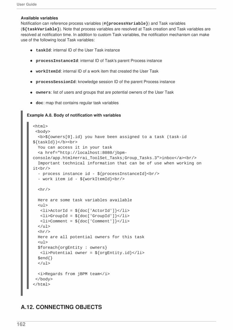
Available variablesNotification can reference process variables (#{processVariable}) and Task variables(${taskVariable}). Note that process variables are resolved at Task creation and Task variables areresolved at notification time. In addition to custom Task variables, the notification mechanism can makeuse of the following local Task variables:
taskId: internal ID of the User Task instance
processInstanceId: internal ID of Task's parent Process instance
workItemId: internal ID of a work item that created the User Task
processSessionId: knowledge session ID of the parent Process instance
owners: list of users and groups that are potential owners of the User Task
doc: map that contains regular task variables
Example A.8. Body of notification with variables
A.12. CONNECTING OBJECTS
<html> <body> <b>${owners[0].id} you have been assigned to a task (task-id ${taskId})</b><br> You can access it in your task <a href="http://localhost:8080/jbpm-console/app.html#errai_ToolSet_Tasks;Group_Tasks.3">inbox</a><br/> Important technical information that can be of use when working on it<br/> - process instance id - ${processInstanceId}<br/> - work item id - ${workItemId}<br/> <hr/> Here are some task variables available <ul> <li>ActorId = ${doc['ActorId']}</li> <li>GroupId = ${doc['GroupId']}</li> <li>Comment = ${doc['Comment']}</li> </ul> <hr/> Here are all potential owners for this task <ul> $foreach{orgEntity : owners} <li>Potential owner = ${orgEntity.id}</li> $end{} </ul> <i>Regards from jBPM team</i> </body></html>
User Guide
162
A.12.1. Connecting Objects
Connecting object connect two elements. There are two main types of Connecting object:
Sequence Flow, which connect Flow elements of a Process and define the flow of the execution(transport the token from one element to another)
Association Flow, which connect any Process elements but have no execution semantics
A.12.2. Connecting Objects types
A.12.2.1. Sequence Flow
A Sequence Flow represents the transition between two Flow elements: it establishes an orientedrelationship between Activities, Events, and Gateways and defines their execution order.
Properties
Condition Expression
A condition that needs to be true to allow the workflow to take the Sequence Flow
If a Sequence Flow has a Gateway element as its source, you need to define a ConditionalExpression, which is evaluated before the Sequence Flow is taken. If false, the workflow attempts toswitch to another Sequence Flow. If true, the Sequence Flow is taken.
When defining the condition in Java, make sure to return a boolean value:
Condition Expression Language
You can use either Java or Drools to define the Condition Expression.
NOTE
When defining a Condition Expression, make sure to call process and global variables.You can also call the kcontext variable, which holds the Process instance information.
A.13. SWIMLANES
Swimlanes are a process element to visually group tasks related to one group or user. For example, youcan create a Marketing task to group all User Tasks related to marketing activities into one Lane.
A.13.1. Lanes
"A Lane is a sub-partition within a Process (often within a Pool)... " [18]
A Lane allows you to group some of the Process elements and define their common parameters. Notethat a Lane may contain another Lane.
return <expression resolving to boolean>;
APPENDIX A. PROCESS ELEMENTS
163
To add a new Lane, open up the Swimlanes menu item in the Object Library to show the Lane artifact.Drag and drop the Lane artifact to your Process Model. This artifact is a box in which you can add yourUser Tasks.
Lanes should be given distinguishing names and background colors to fully separate them into functionalgroups. You can do so by selecting a lane and opening up the Properties panel.
At runtime, Lanes auto-claim/assign task to user who has done another task of that Lane within the sameprocess instance. This user must be eligible for claiming a task, that is, this user must be a potentialowner. If a User Task doesn't have an actor or group assigned it marks the task as having no potentialowners (and therefore, at runtime, the process will just stop).
For example, let's say there are two User Tasks (UT1 and UT2) located in the same Lane. UT1 and UT2have group field set to the analyst value. When the Process is started, and UT1 isclaimed/started/completed by an analyst user, UT2 gets claimed and assigned to the user whocompleted UT1. On the other hand, if only UT1 had the analyst group assigned, and UT2 had no useror group assignments, the process would stop after UT1 had been completed.
A.14. ARTIFACTS
A.14.1. Artifacts
Artifacts are considered any object depicted in the BPMN diagram that are not part of the Processworkflow: they have no incoming or outgoing Flow objects.
The purpose of Artifacts is to provide additional information needed to understand the diagram.
A.14.2. Data Objects
Data Objects are visualizations of Process or Sub-Process variables. Note that not every Process orSub-Process variable must be depicted as a Data Object in the BPMN diagram.
Also note, that Data Objects have the visualization properties and the variable properties.
[1] Business Process Model and Notation (BPMN). Version 2.0, OMG Document Number: formal/2011-01-03http://www.omg.org/spec/BPMN/2.0
[2] Business Process Model and Notation (BPMN) . Version 2.0, OMG Document Number: formal/2011-01-03http://www.omg.org/spec/BPMN/2.0
[3] Business Process Model and Notation (BPMN). Version 2.0, OMG Document Number: formal/2011-01-03http://www.omg.org/spec/BPMN/2.0
[4] Business Process Model and Notation (BPMN). Version 2.0, OMG Document Number: formal/2011-01-03http://www.omg.org/spec/BPMN/2.0
[5] Business Process Model and Notation (BPMN). Version 2.0, OMG Document Number: formal/2011-01-03http://www.omg.org/spec/BPMN/2.0
[6] Business Process Model and Notation (BPMN). Version 2.0, OMG Document Number: formal/2011-01-03http://www.omg.org/spec/BPMN/2.0
[7] Business Process Model and Notation (BPMN) . Version 2.0, OMG Document Number: formal/2011-01-03http://www.omg.org/spec/BPMN/2.0
User Guide
164
[8] Business Process Model and Notation (BPMN). Version 2.0, OMG Document Number: formal/2011-01-03http://www.omg.org/spec/BPMN/2.0
[9] Business Process Model and Notation (BPMN) . Version 2.0, OMG Document Number: formal/2011-01-03http://www.omg.org/spec/BPMN/2.0
[10] Business Process Model and Notation (BPMN) . Version 2.0, OMG Document Number: formal/2011-01-03http://www.omg.org/spec/BPMN/2.0
[11] Business Process Model and Notation (BPMN) . Version 2.0, OMG Document Number: formal/2011-01-03http://www.omg.org/spec/BPMN/2.0
[12] Business Process Model and Notation (BPMN) . Version 2.0, OMG Document Number: formal/2011-01-03http://www.omg.org/spec/BPMN/2.0
[13] Business Process Model and Notation (BPMN). Version 2.0, OMG Document Number: formal/2011-01-03http://www.omg.org/spec/BPMN/2.0
[14] Business Process Model and Notation (BPMN). Version 2.0, OMG Document Number: formal/2011-01-03http://www.omg.org/spec/BPMN/2.0
[15] Business Process Model and Notation (BPMN). Version 2.0, OMG Document Number: formal/2011-01-03http://www.omg.org/spec/BPMN/2.0
[16] Business Process Model and Notation (BPMN). Version 2.0, OMG Document Number: formal/2011-01-03http://www.omg.org/spec/BPMN/2.0
[17] Business Process Model and Notation (BPMN) . Version 2.0, OMG Document Number: formal/2011-01-03http://www.omg.org/spec/BPMN/2.0
[18] Business Process Model and Notation (BPMN) . Version 2.0, OMG Document Number: formal/2011-01-03http://www.omg.org/spec/BPMN/2.0
APPENDIX A. PROCESS ELEMENTS
165
APPENDIX B. SERVICE TASKSFor the convenience of the user, Red Hat JBoss BPM Suite comes with the following predefined types ofService Tasks: Log Task for logging a message to the server standard output (refer to Section B.1, “LogTask”, Email Task for sending emails via the setup mail server (refer to Section B.2, “Email Task”),REST Task for sending REST calls (refer to Section B.3, “REST Task”), and WS Task for invoking webservices as a webservice client (refer to Section B.4, “WS Task”). Note that since the Tasks extend theService Task, their attributes are implemented as Assignments, and DataInputSet and DataOutputSet,not as separate properties.
If other Task types are required, implement your Task as instructed in Section 4.14, “Domain-specificTasks”.
NOTE
Service Task is a Task that uses a service, such as a mail service, web service, oranother system (for further information, refer to the BPMN 2.0 specification).
B.1. LOG TASK
The Log Task is a special type of Service Task that logs an entry in the server log.
Input attributes
Message
the log message text
B.2. EMAIL TASK
The Email Task is a special type of the Service Task that sends an email based on the Task properties.
Input attributes
To
the recipient of the email
From
the sender of the email
Subject
the subject of the email
Body
the body of the email
B.3. REST TASK
The REST Task is a special type of the Service Task that performs REST calls and outputs the responseas an Object.
User Guide
166
Input attributes
Method
the REST method of the call (such as, GET, POST, etc.)
ConnectTimeout
the call timeout
Username
the user name to be used to perform the call
Password
the user password
ReadTimeout
timeout on response receiving
Url
target URL including the request body
Output attributes
Result
string with the result of the call
B.4. WS TASK
The WS Task is a special type Service Task that serves as a web service client with the web serviceresponse stored in the Result String.
Input attributes
Parameter
The object or array to be sent for the operation
Mode
One of SYNC, ASYNC or ONEWAY.
Interface
The name of a service. For example: Weather
Namespace
namespace of the web service, such as http://ws.cdyne.com/WeatherWS//
URL
the web service URL, such as http://ws.cdyne.com/
APPENDIX B. SERVICE TASKS
167

Operation
the actual method name to call
Output attributes
Result
object with the result
User Guide
168
APPENDIX C. SIMULATION DATA
C.1. PROCESS
Simulation attributes
Base currency
currency to be used for simulation
Base time unit
time unit to apply to all time definitions in the Process
C.2. START EVENT
Simulation attributes
Wait time
time to wait as to simulate the execution of the Start Event
Time unit
time unit to be used for the wait time property
C.3. CATCHING INTERMEDIATE EVENTS
Simulation attributes
Wait time
time to wait as to simulate the execution of the Catching Intermediate Event
Time unit
time unit to be used for the wait time property
C.4. SEQUENCE FLOW
Simulation attributes
Probability
probability the Flow is taken in percent
The probability value is applied only if the Flow's source element is a Gateway and there are multipleFlow elements leaving the Gateway. When defining Flow probabilities, make sure their sum is 100.
C.5. THROWING INTERMEDIATE EVENTS
APPENDIX C. SIMULATION DATA
169

Simulation attributes
Distribution type
distribution type to be applied to the processing time values
C.6. HUMAN TASKS
Simulation attributes
Cost per time unit
costs for every time unit lapsed during simulation
Currency
currency of the cost per unit property
Staff availability
number of actors available to work on the given Task
Example C.1. Staff availability impact
Let's assume a simulation of 3 instances of a Process. A new instance is created every 30minutes. The Process contains a None Start Event, a Human Task, and a Simple End Event. TheHuman Task takes 3 hours to complete, the Working hours is set to 3. We have only one personto work on the Human Tasks, that is Staff availability is set to 1. That results in the following:
The Human Task generated by the first Process instance will be executed after 3 hours;
The Human Task generated by the second Process instance will be executed in approx. 6hours (the second Process instance is created after 30 minutes; however, the actor isbusy with the first Task; he becomes available only after another 2.5 hours, and takes 3hours to execute the second Task).
The Human Task generated by the third Process instance will be executed in approx. 9hours (the second Human Task instance is finished after 3 hours; the actor needs another3 hours to complete the third Human Task).
Working hours
time period for simulation of the Task execution
C.7. SERVICE TASKS
Simulation attributes
Cost per time unit
costs for every time unit lapsed during simulation
Currency
currency of the cost per unit property
User Guide
170
Distribution type
distribution type to be applied to the element execution time
C.8. END EVENTS
Simulation attributes
Distribution Type
distribution type to be applied to the element execution time
C.9. DISTRIBUTION TYPES
The Distribution type property defines the distribution of possible time values (scores) of Processelements.
The elements might use one of the following score distribution types on simulation:
normal: bell-shaped, symmetrical
uniform: rectangular distribution; every score (time period) is applied the same number of times
Poisson: negatively skewed normal distribution
C.9.1. Normal
The element values are picked based on the normal distribution type, which is bell-shaped andsymmetrical.
Normal distribution type
Processing time (mean)
mean processing time the element needs to be processed (in time unit defined in the time unitsproperty)
Standard deviation
standard deviation of the processing time (in time unit defined in the time units property)
Time unit
time unit to be used for the mean processing time and standard deviation values
C.9.2. Uniform
The Uniform distribution or rectangular distribution returns the possible values with the same levels ofprobability.
Uniform distribution type
Processing time (max)
APPENDIX C. SIMULATION DATA
171
maximum processing time of the element
Processing time (min)
minimum processing time of the element
Time unit
time unit to be used for the processing time values
C.9.3. Poisson
The Poisson distribution returns the possible values similarly as normal distribution; however, thedistribution is negatively skewed, not symmetrical.The mean and the variant are equal.
Poisson distribution type
Processing time (mean)
mean time for the element processing (in time unit defined in the time units property)
Time unit
time unit to be used for the mean processing time
User Guide
172

APPENDIX D. REVISION HISTORY
Revision 1.0.0-43 Thu Dec 17 2015 Vidya IyengarBuild includes various enhancements and fixes
APPENDIX D. REVISION HISTORY
173