Red Hat Enterprise Linux OpenStack Platform 4.0 (Havana ... · This Red Hat Enterprise Linux...
104
Red Hat Enterprise Linux OpenStack Platform 4.0 (Havana) on Cisco UCS and Cisco Nexus Implementation Guide July 17, 2014 Building Architectures to Solve Business Problems
Transcript of Red Hat Enterprise Linux OpenStack Platform 4.0 (Havana ... · This Red Hat Enterprise Linux...
Red Hat Enterprise Linux OpenStack Platform 4.0(Havana) on Cisco UCS and Cisco NexusImplementation GuideJuly 17, 2014
Building Architectures to Solve Business Problems

Cisco and the Cisco logo are trademarks or registered trademarks of Cisco and/or its affiliates in the U.S. and other countries. To view a list of Cisco trademarks, go to thisURL: www.cisco.com/go/trademarks. Third-party trademarks mentioned are the property of their respective owners. The use of the word partner does not imply a partnershiprelationship between Cisco and any other company. (1110R)
THE SOFTWARE LICENSE AND LIMITED WARRANTY FOR THE ACCOMPANYING PRODUCT ARE SET FORTH IN THE INFORMATION PACKET THAT SHIPPED WITH THE PRODUCT AND ARE INCORPORATED HEREIN BY THIS REFERENCE. IF YOU ARE UNABLE TO LOCATE THE SOFTWARE LICENSE OR LIMITED WARRANTY, CONTACT YOUR CISCO REPRESENTATIVE FOR A COPY.
The Cisco implementation of TCP header compression is an adaptation of a program developed by the University of California, Berkeley (UCB) as part of UCB’s public domain version of the UNIX operating system. All rights reserved. Copyright © 1981, Regents of the University of California.
NOTWITHSTANDING ANY OTHER WARRANTY HEREIN, ALL DOCUMENT FILES AND SOFTWARE OF THESE SUPPLIERS ARE PROVIDED “AS IS” WITH ALL FAULTS. CISCO AND THE ABOVE-NAMED SUPPLIERS DISCLAIM ALL WARRANTIES, EXPRESSED OR IMPLIED, INCLUDING, WITHOUT LIMITATION, THOSE OF MERCHANTABILITY, FITNESS FOR A PARTICULAR PURPOSE AND NONINFRINGEMENT OR ARISING FROM A COURSE OF DEALING, USAGE, OR TRADE PRACTICE.
IN NO EVENT SHALL CISCO OR ITS SUPPLIERS BE LIABLE FOR ANY INDIRECT, SPECIAL, CONSEQUENTIAL, OR INCIDENTAL DAMAGES, INCLUDING, WITHOUT LIMITATION, LOST PROFITS OR LOSS OR DAMAGE TO DATA ARISING OUT OF THE USE OR INABILITY TO USE THIS MANUAL, EVEN IF CISCO OR ITS SUPPLIERS HAVE BEEN ADVISED OF THE POSSIBILITY OF SUCH DAMAGES.
Red Hat Enterprise Linux OpenStack Platform 4.0 (Havana) on Cisco UCS and Cisco Nexus Implementation Guide© 2014 Cisco Systems, Inc. All rights reserved.
Red Hat EImplementation Guide
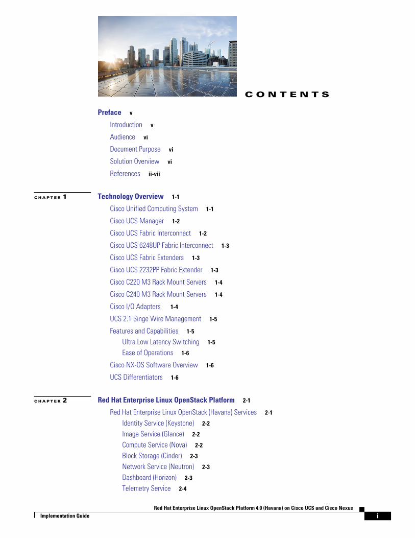
C O N T E N T S
Preface v
Introduction v
Audience vi
Document Purpose vi
Solution Overview vi
References ii-vii
C H A P T E R 1 Technology Overview 1-1
Cisco Unified Computing System 1-1
Cisco UCS Manager 1-2
Cisco UCS Fabric Interconnect 1-2
Cisco UCS 6248UP Fabric Interconnect 1-3
Cisco UCS Fabric Extenders 1-3
Cisco UCS 2232PP Fabric Extender 1-3
Cisco C220 M3 Rack Mount Servers 1-4
Cisco C240 M3 Rack Mount Servers 1-4
Cisco I/O Adapters 1-4
UCS 2.1 Singe Wire Management 1-5
Features and Capabilities 1-5
Ultra Low Latency Switching 1-5
Ease of Operations 1-6
Cisco NX-OS Software Overview 1-6
UCS Differentiators 1-6
C H A P T E R 2 Red Hat Enterprise Linux OpenStack Platform 2-1
Red Hat Enterprise Linux OpenStack (Havana) Services 2-1
Identity Service (Keystone) 2-2
Image Service (Glance) 2-2
Compute Service (Nova) 2-2
Block Storage (Cinder) 2-3
Network Service (Neutron) 2-3
Dashboard (Horizon) 2-3
Telemetry Service 2-4
interprise Linux OpenStack Platform 4.0 (Havana) on Cisco UCS and Cisco Nexus
Contents
Heat (Orchestration Service) 2-4
Ceph Storage for OpenStack 2-5
Red Hat Enterprise Linux 2-5
Supporting Technologies 2-6
C H A P T E R 3 Architectural Overview 3-1
Virtual Networking 3-3
Storage Virtualization 3-3
Service Profile Design 3-4
Network High Availability Design 3-5
OpenStack Services Placement 3-5
Sizing Guidelines 3-6
Defining the Reference Workload 3-6
C H A P T E R 4 Configuration Guidelines 4-1
Connecting Network Cables 4-1
Preparing Cisco UCS FI Manager and Configure Manager 4-3
Initial Configuration of Cisco UCS FIs 4-3
Configuration for Server Discovery 4-5
Upstream/ Global Network Configuration 4-8
Configure Identifier Pools 4-10
Configure Server Pool and Qualifying Policy 4-14
Configure Service Profile Template 4-21
Instantiate Service Profiles from the Service Profile Template 4-33
Cisco Nexus Plug-in for OpenStack Networking 4-36
Product Description 4-36
VLAN Programming 4-36
Multi-Homed Host Deployments 4-37
Support for OpenStack Neutron Provider Networks 4-37
Cisco Nexus Plug-in and Modular Layer 2 Cisco Nexus Driver 4-37
Support for Cisco Nexus 3000, 5000, 6000, and 7000 Series Switches 4-37
Creating OpenStack Setup on Nexus Plug-in Based Topology 4-38
Foreman Installation 4-38
Prerequisites and Getting the Red Hat Enterprise Linux 6.5 ISO 4-38
Installation of the Build Node 4-41
Subscribing to Red hat 4-41
Using Subscription Manager 4-41
Using Classic RHN (Red Hat Network) 4-43
iiRed Hat Enterprise Linux OpenStack Platform 4.0 (Havana) on Cisco UCS and Cisco Nexus
Implementation Guide
Contents
Configuring the Firewall 4-44
Installing Foreman Packages 4-44
Workaround for Known Issues 4-45
Configuring the Foreman Server 4-46
Modify Settings 4-46
Set Installation Media 4-47
Provide Activation Keys 4-48
Configure Operating Systems for PXE Installed Systems 4-50
Configure Provisioning Template 4-51
Configuring Host Groups 4-52
Controller Host Group Configuration 4-53
Compute Host Group Configuration 4-55
Networker Node Host Group Configuration 4-57
Installation of Controller and Compute and Network Nodes 4-59
Installing Nodes via PXE (Provisioning Method) 4-60
Adding Nodes Manually (Non-Provisioning Method) 4-61
Workaround for Known Bugs after Installing Nodes 4-62
Workaround for Isolating Metadata 4-62
Workaround for Correcting the Neutron init-script for the Cisco Neutron Plugin 4-62
Ink Tank Ceph Installation 4-63
Pre-Requisite 4-63
Configuring Ink Tank Repositories 4-63
Installing Ceph Deploy 4-64
Setting up Ceph Nodes 4-64
Creating a Ceph Storage Cluster 4-65
Preparing the Ceph OSD Nodes 4-66
Create OSD Pools 4-66
Configuring OpenStack to use Ceph 4-66
Known Issues with Ceph 4-68
A P P E N D I X A Caveats A-1
A P P E N D I X B Bill of Materials B-1
A P P E N D I X C Verified Components C-1
iiiRed Hat Enterprise Linux OpenStack Platform 4.0 (Havana) on Cisco UCS and Cisco Nexus
Implementation Guide

Contents
ivRed Hat Enterprise Linux OpenStack Platform 4.0 (Havana) on Cisco UCS and Cisco Nexus
Implementation Guide
Preface
OpenStack is a free and open source Infrastructure-as-a-Service (IaaS) cloud computing project released under the Apache License. It enables enterprises and service providers to offer on-demand computing resources by provisioning and managing large networks of virtual machines. Red Hat's OpenStack technology uses upstream OpenStack open source architecture and enhances it for Enterprise and service provider customers with better support structure. The Cisco Unified Computing System with Cisco Nexus is a next-generation data center platform that unites computing, network, storage access, and virtualization into a single cohesive system. Cisco UCS with nexus is an ideal platform for the OpenStack architecture.
• Combination of Cisco UCS platform, Nexus and Red Hat Enterprise Linux OpenStack Platform architecture accelerates your IT.
• Transformation by enabling faster deployments, greater flexibility of choice, efficiency, and lower risk.
• This Cisco Validated Design document focuses on the Red Hat Enterprise Linux Platform on UCS and Nexus Platform for small to medium size business segments.
IntroductionVirtualization is a key and critical strategic deployment model for reducing the Total Cost of Ownership (TCO) and achieving better utilization of the platform components like hardware, software, network and storage. However choosing the appropriate platform for virtualization can be a tricky task. The platform should be flexible, reliable, and cost effective to facilitate the virtualization platform to deploy various enterprise applications. Also the ability to slice and dice the underlying platform to size the application is an essential requirement for a virtualization platform to utilize compute, network, and storage resources effectively.
In this regard, the Cisco UCS solution implementing Red Hat Enterprise Linux OpenStack Platform provides a very simplistic yet fully integrated and validated infrastructure for you to deploy VMs in various sizes to suite your application needs. The Cisco Nexus® Switches are high-performance, high-density Ethernet switches that are part of the Cisco Network portfolio. These compact one-rack-unit (1RU) form-factor 10 Gigabit Ethernet switches provide line-rate Layer 2 and 3 switching. They run the industry-leading Cisco®NX OS Software operating system, providing customers with comprehensive features and functions that are widely deployed globally. They support both forward and
vRed Hat Enterprise Linux OpenStack Platform 4.0 (Havana) on Cisco UCS and Cisco Nexus
Implementation Guide
Preface
reverse airflow schemes with AC and DC power inputs. The Cisco Nexus 3064 switches are well suited for data centers that require cost-effective, power-efficient, line-rate Layer 2 and 3 top-of-rack (ToR) switches.
AudienceThe reader of this document is expected to have the necessary training and background to install and configure Red Hat Enterprise Linux, Cisco Unified Computing System (UCS), Cisco Nexus and Unified Computing Systems Manager as well as high level understanding of OpenStack components. External references are provided where applicable and it is recommended that the reader be familiar with these documents.
Readers are also expected to be familiar with the infrastructure and network and security policies of the customer installation.
Document PurposeThis document describes the steps required to deploy and configure Red Hat Enterprise Linux OpenStack Platform architecture on Cisco UCS and Cisco Nexus platform to a level that will allow for confirmation that the basic components and connections are working correctly. The document addresses Small- to Medium-sized Businesses; however the architecture can be very easily expanded with predictable linear performance. While readers of this document are expected to have sufficient knowledge to install and configure the products used, configuration details that are important to this solution's deployment s are specifically mentioned.
Solution OverviewThis Red Hat Enterprise Linux OpenStack Platform architecture on a Cisco UCS and Cisco Nexus platform solution provides an end-to-end architecture with Cisco, Red Hat, and OpenStack technologies that demonstrate high availability and server redundancy along with ease of deployment and use.
The following are the components used for the design and deployment:
• Cisco Nexus Top of Rack Switch
• Cisco Unified Compute System (UCS) 2.1(3b)
• Cisco C-Series Unified Computing System servers for compute and storage needs
• Cisco UCS VIC adapters
• Red Hat Enterprise Linux OpenStack Platform 4.0 architecture
• CEPH storage module supported by Ink Tank
viRed Hat Enterprise Linux OpenStack Platform 4.0 (Havana) on Cisco UCS and Cisco Nexus
Implementation Guide
PrefaceReferences
ReferencesThe following references are available for consideration.
• Cisco UCS
• Cisco UCSM 2.1 Configuration Guides
• Red Hat OpenStack 4 Reference Architecture
• Ceph Installation and Configuration
• Cisco Nexus 3k Series Switch
• Cisco Nexus 3064 Switch
viiRed Hat Enterprise Linux OpenStack Platform 4.0 (Havana) on Cisco UCS and Cisco Nexus
Implementation Guide

PrefaceReferences
viiiRed Hat Enterprise Linux OpenStack Platform 4.0 (Havana) on Cisco UCS and Cisco Nexus
Implementation Guide
Red Hat Enterprise Linux OpenStack PImplementation Guide
C H A P T E R 1
Technology OverviewIn this chapter the following UCS technology areas are detailed.
• Cisco Unified Computing System, page 1-1
• Cisco UCS Manager, page 1-2
• Cisco UCS Fabric Interconnect, page 1-2
• Cisco UCS 6248UP Fabric Interconnect, page 1-3
• Cisco UCS Fabric Extenders, page 1-3
• Cisco UCS 2232PP Fabric Extender, page 1-3
• Cisco C220 M3 Rack Mount Servers, page 1-4
• Cisco C240 M3 Rack Mount Servers, page 1-4
• Cisco I/O Adapters , page 1-4
• UCS 2.1 Singe Wire Management, page 1-5
Cisco Unified Computing SystemThe Cisco Unified Computing System is a next-generation data center platform that unites compute, network, and storage access. The platform, optimized for virtual environments, is designed using open industry-standard technologies and aims to reduce total cost of ownership (TCO) and increase business agility. The system integrates a low-latency; lossless 10 Gigabit Ethernet unified network fabric with enterprise-class, x86-architecture servers. It is an integrated, scalable, multi chassis platform in which all resources participate in a unified management domain.
The main components of the Cisco Unified Computing System are:
• Computing—The system is based on an entirely new class of computing system that incorporates blade servers based on Intel Xeon E5-2650 V2 Series Processors. The Cisco UCS servers offer the patented Cisco Extended Memory Technology to support applications with large datasets and allow more virtual machines per server.
• Network—The system is integrated onto a low-latency, lossless, 10-Gbps unified network fabric. This network foundation consolidates LANs, SANs, and high-performance computing networks which are separate networks today. The unified fabric lowers costs by reducing the number of network adapters, switches, and cables, and by decreasing the power and cooling requirements.
1-1latform 4.0 (Havana) on Cisco UCS and Cisco Nexus
Chapter 1 Technology OverviewCisco UCS Manager
• Virtualization—The system unleashes the full potential of virtualization by enhancing the scalability, performance, and operational control of virtual environments. Cisco security, policy enforcement, and diagnostic features are now extended into virtualized environments to better support changing business and IT requirements.
• Storage Access—Cisco C-Series servers can host large number of local SATA hard disks. The system provides consolidated access to both SAN storage and Network Attached Storage (NAS) over the unified fabric. By unifying the storage access the Cisco Unified Computing System can access storage over Ethernet, Fibre Channel, Fibre Channel over Ethernet (FCoE), and iSCSI. This provides customers with choice for storage access and investment protection. In addition, the server administrators can preassign storage access policies for system connectivity to storage resources, simplifying storage connectivity, and management for increased productivity.
The Cisco Unified Computing System is designed to deliver:
• A reduced Total Cost of Ownership (TCO) and increased business agility.
• Increased IT staff productivity through just-in-time provisioning and mobility support.
• A cohesive, integrated system, which unifies the technology in the data center.
• Industry standards supported by a partner ecosystem of industry leaders.
Cisco UCS ManagerCisco UCS Manager provides unified, embedded management of all software and hardware components of the Cisco Unified Computing System through an intuitive GUI, a command line interface (CLI), or an XML API. The Cisco UCS Manager provides unified management domain with centralized management capabilities and controls multiple chassis and thousands of virtual machines.
Cisco UCS Fabric InterconnectThe Cisco® UCS 6200 Series Fabric Interconnect is a core part of the Cisco Unified Computing System, providing both network connectivity and management capabilities for the system. The Cisco UCS 6200 Series offers line-rate, low-latency, lossless 10 Gigabit Ethernet, Fiber Channel over Ethernet (FCoE) and Fiber Channel functions.
The Cisco UCS 6200 Series provides the management and communication backbone for the Cisco UCS C-Series Servers. All servers are attached to the Cisco UCS 6200 Series Fabric Interconnects become part of a single, highly available management domain. In addition, by supporting unified fabric, the Cisco UCS 6200 Series provides both the LAN and SAN connectivity for all blades within its domain.
From a networking perspective, the Cisco UCS 6200 Series uses a cut-through architecture, supporting deterministic, low-latency, line-rate 10 Gigabit Ethernet on all ports, 1Tb switching capacity, 160 Gbps bandwidth per chassis, independent of packet size and enabled services. The product family supports Cisco low-latency, lossless 10 Gigabit Ethernet unified network fabric capabilities, which increase the reliability, efficiency, and scalability of Ethernet networks. The Fabric Interconnect supports multiple traffic classes over a lossless Ethernet fabric from a blade server through an interconnect. Significant TCO savings come from an FCoE-optimized server design in which network interface cards (NICs), host bus adapters (HBAs), cables, and switches can be consolidated.
1-2Red Hat Enterprise Linux OpenStack Platform 4.0 (Havana) on Cisco UCS and Cisco Nexus
Implementation Guide
Chapter 1 Technology OverviewCisco UCS 6248UP Fabric Interconnect
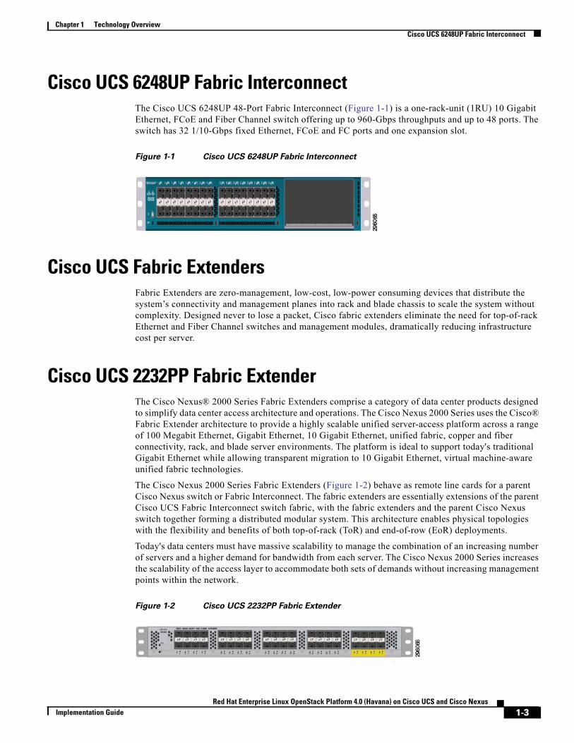
Cisco UCS 6248UP Fabric InterconnectThe Cisco UCS 6248UP 48-Port Fabric Interconnect (Figure 1-1) is a one-rack-unit (1RU) 10 Gigabit Ethernet, FCoE and Fiber Channel switch offering up to 960-Gbps throughputs and up to 48 ports. The switch has 32 1/10-Gbps fixed Ethernet, FCoE and FC ports and one expansion slot.
Figure 1-1 Cisco UCS 6248UP Fabric Interconnect
Cisco UCS Fabric ExtendersFabric Extenders are zero-management, low-cost, low-power consuming devices that distribute the system’s connectivity and management planes into rack and blade chassis to scale the system without complexity. Designed never to lose a packet, Cisco fabric extenders eliminate the need for top-of-rack Ethernet and Fiber Channel switches and management modules, dramatically reducing infrastructure cost per server.
Cisco UCS 2232PP Fabric ExtenderThe Cisco Nexus® 2000 Series Fabric Extenders comprise a category of data center products designed to simplify data center access architecture and operations. The Cisco Nexus 2000 Series uses the Cisco® Fabric Extender architecture to provide a highly scalable unified server-access platform across a range of 100 Megabit Ethernet, Gigabit Ethernet, 10 Gigabit Ethernet, unified fabric, copper and fiber connectivity, rack, and blade server environments. The platform is ideal to support today's traditional Gigabit Ethernet while allowing transparent migration to 10 Gigabit Ethernet, virtual machine-aware unified fabric technologies.
The Cisco Nexus 2000 Series Fabric Extenders (Figure 1-2) behave as remote line cards for a parent Cisco Nexus switch or Fabric Interconnect. The fabric extenders are essentially extensions of the parent Cisco UCS Fabric Interconnect switch fabric, with the fabric extenders and the parent Cisco Nexus switch together forming a distributed modular system. This architecture enables physical topologies with the flexibility and benefits of both top-of-rack (ToR) and end-of-row (EoR) deployments.
Today's data centers must have massive scalability to manage the combination of an increasing number of servers and a higher demand for bandwidth from each server. The Cisco Nexus 2000 Series increases the scalability of the access layer to accommodate both sets of demands without increasing management points within the network.
Figure 1-2 Cisco UCS 2232PP Fabric Extender
1-3Red Hat Enterprise Linux OpenStack Platform 4.0 (Havana) on Cisco UCS and Cisco Nexus
Implementation Guide
Chapter 1 Technology OverviewCisco C220 M3 Rack Mount Servers
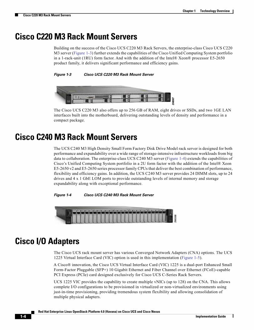
Cisco C220 M3 Rack Mount ServersBuilding on the success of the Cisco UCS C220 M3 Rack Servers, the enterprise-class Cisco UCS C220 M3 server (Figure 1-3) further extends the capabilities of the Cisco Unified Computing System portfolio in a 1-rack-unit (1RU) form factor. And with the addition of the Intel® Xeon® processor E5-2650 product family, it delivers significant performance and efficiency gains.
Figure 1-3 Cisco UCS C220 M3 Rack Mount Server
The Cisco UCS C220 M3 also offers up to 256 GB of RAM, eight drives or SSDs, and two 1GE LAN interfaces built into the motherboard, delivering outstanding levels of density and performance in a compact package.
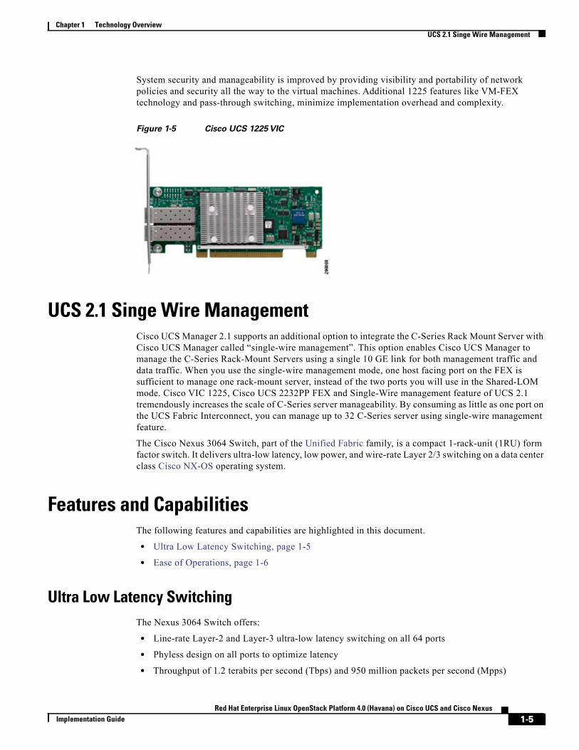
Cisco C240 M3 Rack Mount ServersThe UCS C240 M3 High Density Small Form Factory Disk Drive Model rack server is designed for both performance and expandability over a wide range of storage-intensive infrastructure workloads from big data to collaboration. The enterprise-class UCS C240 M3 server (Figure 1-4) extends the capabilities of Cisco’s Unified Computing System portfolio in a 2U form factor with the addition of the Intel® Xeon E5-2650 v2 and E5-2650 series processor family CPUs that deliver the best combination of performance, flexibility and efficiency gains. In addition, the UCS C240 M3 server provides 24 DIMM slots, up to 24 drives and 4 x 1 GbE LOM ports to provide outstanding levels of internal memory and storage expandability along with exceptional performance.
Figure 1-4 Cisco UCS C240 M3 Rack Mount Server
Cisco I/O AdaptersThe Cisco UCS rack mount server has various Converged Network Adapters (CNA) options. The UCS 1225 Virtual Interface Card (VIC) option is used in this implementation (Figure 1-5).
A Cisco® innovation, the Cisco UCS Virtual Interface Card (VIC) 1225 is a dual-port Enhanced Small Form-Factor Pluggable (SFP+) 10 Gigabit Ethernet and Fiber Channel over Ethernet (FCoE)-capable PCI Express (PCIe) card designed exclusively for Cisco UCS C-Series Rack Servers.
UCS 1225 VIC provides the capability to create multiple vNICs (up to 128) on the CNA. This allows complete I/O configurations to be provisioned in virtualized or non-virtualized environments using just-in-time provisioning, providing tremendous system flexibility and allowing consolidation of multiple physical adapters.
1-4Red Hat Enterprise Linux OpenStack Platform 4.0 (Havana) on Cisco UCS and Cisco Nexus
Implementation Guide
Chapter 1 Technology OverviewUCS 2.1 Singe Wire Management
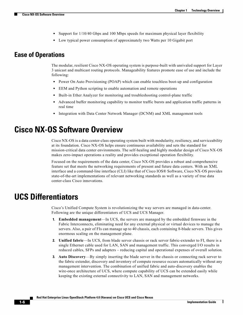
System security and manageability is improved by providing visibility and portability of network policies and security all the way to the virtual machines. Additional 1225 features like VM-FEX technology and pass-through switching, minimize implementation overhead and complexity.
Figure 1-5 Cisco UCS 1225 VIC
UCS 2.1 Singe Wire ManagementCisco UCS Manager 2.1 supports an additional option to integrate the C-Series Rack Mount Server with Cisco UCS Manager called “single-wire management”. This option enables Cisco UCS Manager to manage the C-Series Rack-Mount Servers using a single 10 GE link for both management traffic and data traffic. When you use the single-wire management mode, one host facing port on the FEX is sufficient to manage one rack-mount server, instead of the two ports you will use in the Shared-LOM mode. Cisco VIC 1225, Cisco UCS 2232PP FEX and Single-Wire management feature of UCS 2.1 tremendously increases the scale of C-Series server manageability. By consuming as little as one port on the UCS Fabric Interconnect, you can manage up to 32 C-Series server using single-wire management feature.
The Cisco Nexus 3064 Switch, part of the Unified Fabric family, is a compact 1-rack-unit (1RU) form factor switch. It delivers ultra-low latency, low power, and wire-rate Layer 2/3 switching on a data center class Cisco NX-OS operating system.
Features and CapabilitiesThe following features and capabilities are highlighted in this document.
• Ultra Low Latency Switching, page 1-5
• Ease of Operations, page 1-6
Ultra Low Latency SwitchingThe Nexus 3064 Switch offers:
• Line-rate Layer-2 and Layer-3 ultra-low latency switching on all 64 ports
• Phyless design on all ports to optimize latency
• Throughput of 1.2 terabits per second (Tbps) and 950 million packets per second (Mpps)
1-5Red Hat Enterprise Linux OpenStack Platform 4.0 (Havana) on Cisco UCS and Cisco Nexus
Implementation Guide
Chapter 1 Technology OverviewCisco NX-OS Software Overview
• Support for 1/10/40 Gbps and 100 Mbps speeds for maximum physical layer flexibility
• Low typical power consumption of approximately two Watts per 10 Gigabit port
Ease of OperationsThe modular, resilient Cisco NX-OS operating system is purpose-built with unrivaled support for Layer 3 unicast and multicast routing protocols. Manageability features promote ease of use and include the following:
• Power On Auto Provisioning (POAP) which can enable touchless boot-up and configuration
• EEM and Python scripting to enable automation and remote operations
• Built-in Ether Analyzer for monitoring and troubleshooting control-plane traffic
• Advanced buffer monitoring capability to monitor traffic bursts and application traffic patterns in real time
• Integration with Data Center Network Manager (DCNM) and XML management tools
Cisco NX-OS Software OverviewCisco NX-OS is a data center-class operating system built with modularity, resiliency, and serviceability at its foundation. Cisco NX-OS helps ensure continuous availability and sets the standard for mission-critical data center environments. The self-healing and highly modular design of Cisco NX-OS makes zero-impact operations a reality and provides exceptional operation flexibility.
Focused on the requirements of the data center, Cisco NX-OS provides a robust and comprehensive feature set that meets the networking requirements of present and future data centers. With an XML interface and a command-line interface (CLI) like that of Cisco IOS® Software, Cisco NX-OS provides state-of-the-art implementations of relevant networking standards as well as a variety of true data center-class Cisco innovations.
UCS DifferentiatorsCisco’s Unified Compute System is revolutionizing the way servers are managed in data-center. Following are the unique differentiators of UCS and UCS Manager.
1. Embedded management—In UCS, the servers are managed by the embedded firmware in the Fabric Interconnects, eliminating need for any external physical or virtual devices to manage the servers. Also, a pair of FIs can manage up to 40 chassis, each containing 8-blade servers. This gives enormous scaling on the management plane.
2. Unified fabric—In UCS, from blade server chassis or rack server fabric-extender to FI, there is a single Ethernet cable used for LAN, SAN and management traffic. This converged I/O results in reduced cables, SFPs and adapters – reducing capital and operational expenses of overall solution.
3. Auto Discovery—By simply inserting the blade server in the chassis or connecting rack server to the fabric extender, discovery and inventory of compute resource occurs automatically without any management intervention. The combination of unified fabric and auto-discovery enables the wire-once architecture of UCS, where compute capability of UCS can be extended easily while keeping the existing external connectivity to LAN, SAN and management networks.
1-6Red Hat Enterprise Linux OpenStack Platform 4.0 (Havana) on Cisco UCS and Cisco Nexus
Implementation Guide
Chapter 1 Technology OverviewUCS Differentiators
4. Policy based resource classification—Once a compute resource is discovered by UCS Manager, it can be automatically classified to a given resource pool based on policies defined. This capability is useful in multi-tenant cloud computing. This CVD showcases the policy based resource classification of UCS Manager.
5. Combined Rack and Blade server management—UCS Manager can manage B-series blade servers and C-series rack server under the same UCS domain. This feature, along with stateless computing makes compute resources truly hardware form factor agnostic. In this CVD, we are showcasing combinations of B and C series servers to demonstrate stateless and form-factor independent computing work load.
6. Model based management architecture—UCS Manager architecture and management database is model based and data driven. An open, standard based XML API is provided to operate on the management model. This enables easy and scalable integration of UCS Manager with other management system, such as VMware vCloud director, Microsoft System Center, and Citrix Cloud Platform.
7. Policies, Pools, Templates—The management approach in UCS Manager is based on defining policies, pools and templates, instead of cluttered configuration, which enables a simple, loosely coupled, data driven approach in managing compute, network and storage resources.
8. Loose referential integrity—In UCS Manager, a service profile, port profile or policies can refer to other policies or logical resources with loose referential integrity. A referred policy cannot exist at the time of authoring the referring policy or a referred policy can be deleted even though other policies are referring to it. This provides different subject matter experts to work independently from each-other. This provides great flexibility where different experts from different domains, such as network, storage, security, server and virtualization work together to accomplish a complex task.
9. Policy resolution—In UCS Manager, a tree structure of organizational unit hierarchy can be created that mimics the real life tenants and/or organization relationships. Various policies, pools and templates can be defined at different levels of organization hierarchy. A policy referring to another policy by name is resolved in the organization hierarchy with closest policy match. If no policy with specific name is found in the hierarchy of the root organization, then special policy named “default” is searched. This policy resolution practice enables automation friendly management APIs and provides great flexibility to owners of different organizations.
10. Service profiles and stateless computing—A service profile is a logical representation of a server, carrying its various identities and policies. This logical server can be assigned to any physical compute resource as far as it meets the resource requirements. Stateless computing enables procurement of a server within minutes, which used to take days in legacy server management systems.
11. Built-in multi-tenancy support—The combination of policies, pools and templates, loose referential integrity, policy resolution in organization hierarchy and a service profiles based approach to compute resources makes UCS Manager inherently friendly to multi-tenant environment typically observed in private and public clouds.
12. Extended Memory—The extended memory architecture of UCS servers allows up to 760 GB RAM per server – allowing huge VM to physical server ratio required in many deployments, or allowing large memory operations required by certain architectures like Big-Data.
13. Virtualization aware network—VM-FEX technology makes access layer of network aware about host virtualization. This prevents domain pollution of compute and network domains with virtualization when virtual network is managed by port-profiles defined by the network administrators’ team. VM-FEX also off loads hypervisor CPU by performing switching in the hardware, thus allowing hypervisor CPU to do more virtualization related tasks. VM-FEX technology is well integrated with VMware vCenter, Linux KVM and Hyper-V SR-IOV to simplify cloud management.
1-7Red Hat Enterprise Linux OpenStack Platform 4.0 (Havana) on Cisco UCS and Cisco Nexus
Implementation Guide

Chapter 1 Technology OverviewUCS Differentiators
14. Simplified QoS—Even though Fiber Channel and Ethernet are converged in UCS fabric, built-in support for QoS and lossless Ethernet makes it seamless. Network Quality of Service (QoS) is simplified in UCS Manager by representing all system classes in one GUI panel.
1-8Red Hat Enterprise Linux OpenStack Platform 4.0 (Havana) on Cisco UCS and Cisco Nexus
Implementation Guide
Red Hat Enterprise Linux OpenStack PImplementation Guide
C H A P T E R 2
Red Hat Enterprise Linux OpenStack PlatformRed Hat Enterprise Linux OpenStack Platform provides the foundation to build private or public Infrastructure-as-a-Service (IaaS) for cloud-enabled workloads. It allows organizations to leverage OpenStack, the largest and fastest growing open source cloud infrastructure project, while maintaining the security, stability, and enterprise readiness of a platform built on Red Hat Enterprise Linux.
Red Hat Enterprise Linux OpenStack Platform gives organizations a truly open framework for hosting cloud workloads, delivered by Red Hat subscription for maximum flexibility and cost effectiveness. In conjunction with other Red Hat technologies, Red Hat Enterprise Linux OpenStack Platform allows organizations to move from traditional workloads to cloud-enabled workloads on their own terms and time lines, as their applications require. Red Hat frees organizations from proprietary lock-in, and allows them to move to open technologies while maintaining their existing infrastructure investments.
Unlike other OpenStack distributions, Red Hat Enterprise Linux OpenStack Platform provides a certified ecosystem of hardware, software, and services, an enterprise life cycle that extends the community OpenStack release cycle, and award-winning Red Hat support on both the OpenStack modules and their underlying Linux dependencies. Red Hat delivers long-term commitment and value from a proven enterprise software partner so organizations can take advantage of the fast pace of OpenStack development without risking stability and supportability of their production environments.
Red Hat Enterprise Linux OpenStack (Havana) ServicesRed Hat Enterprise Linux OpenStack Platform 4 is based on the upstream Havana OpenStack release. Red Hat Enterprise Linux OpenStack Platform 4 is the fourth release from Red Hat. The first release was based on the Essex OpenStack release. The second release was based on the Folsom OpenStack release. It was the first release to include extensible block and volume storage services. The third release was based on grizzly.
The following OpenStack components are discussed.
• Identity Service (Keystone), page 2-2
• Image Service (Glance), page 2-2
• Compute Service (Nova), page 2-2
• Block Storage (Cinder), page 2-3
• Network Service (Neutron), page 2-3
• Dashboard (Horizon), page 2-3
• Telemetry Service, page 2-4
• Heat (Orchestration Service), page 2-4
2-1latform 4.0 (Havana) on Cisco UCS and Cisco Nexus
Chapter 2 Red Hat Enterprise Linux OpenStack PlatformRed Hat Enterprise Linux OpenStack (Havana) Services
Identity Service (Keystone)This is a central authentication and authorization mechanism for all OpenStack users and services. It supports multiple forms of authentication including standard username and password credentials, token-based systems and AWS-style logins that use public/private key pairs. It can also integrate with existing directory services such as LDAP.
The Identity service catalog lists all of the services deployed in an OpenStack cloud and manages authentication for them through endpoints. An endpoint is a network address where a service listens for requests. The Identity service provides each OpenStack service – such as Image, Compute, or Block Storage—with one or more endpoints.
The Identity service uses tenants to group or isolate resources. By default users in one tenant can’t access resources in another even if they reside within the same OpenStack cloud deployment or physical host. The Identity service issues tokens to authenticated users. The endpoints validate the token before allowing user access. User accounts are associated with roles that define their access credentials. Multiple users can share the same role within a tenant.
The Identity Service is comprised of the keystone service, which responds to service requests, places messages in queue, grants access tokens, and updates the state database.
Image Service (Glance)This service discovers, registers, and delivers virtual machine images. They can be copied via snapshot and immediately stored as the basis for new instance deployments. Stored images allow OpenStack users and administrators to provision multiple servers quickly and consistently. The Image Service API provides a standard RESTful interface for querying information about the images.
By default the Image Service stores images in the /var/lib/glance/images directory of the local server’s file system where Glance is installed. The Glance API can also be configured to cache images to reduce image staging time. The Image Service supports multiple back end storage technologies including Swift (the OpenStack Object Storage service), Amazon S3, and Red Hat Storage Server.
The Image service is composed of the openstack-glance-api that delivers image information from the registry service, and the openstack-glance-registry, which manages the metadata, associated with each image.
Compute Service (Nova)OpenStack Compute provisions and manages large networks of virtual machines. It is the backbone of OpenStack’s IaaS functionality. OpenStack Compute scales horizontally on standard hardware enabling the favorable economics of cloud computing. Users and administrators interact with the compute fabric via a web interface and command line tools.
Key features of OpenStack Compute include:
• Distributed and asynchronous architecture, allowing scale out fault tolerance for virtual machine instance management
• Management of commodity virtual server resources, where predefined virtual hardware profiles for guests can be assigned to new instances at launch
• Tenants to separate and control access to compute resources
• VNC access to instances via web browsers
2-2Red Hat Enterprise Linux OpenStack Platform 4.0 (Havana) on Cisco UCS and Cisco Nexus
Implementation Guide
Chapter 2 Red Hat Enterprise Linux OpenStack PlatformRed Hat Enterprise Linux OpenStack (Havana) Services
OpenStack Compute is composed of many services that work together to provide the full functionality. The openstack-nova-cert and openstack-nova-consoleauth services handle authorization. The openstack-nova-api responds to service requests and the openstack-nova-scheduler dispatches the requests to the message queue. The openstack-nova-conductor service updates the state database, which limits direct access to the state database by compute nodes for increased security. The openstack nova-compute service creates and terminates virtual machine instances on the compute nodes. Finally, openstack-nova-novncproxy provides a VNC proxy for console access to virtual machines via a standard web browser.
Block Storage (Cinder)While the OpenStack Compute service provisions ephemeral storage for deployed instances based on their hardware profiles, the OpenStack Block Storage service provides compute instances with persistent block storage. Block storage is appropriate for performance sensitive scenarios such as databases or frequently accessed file systems. Persistent block storage can survive instance termination. It can also be moved between instances like any external storage device. This service can be backed by a variety of enterprise storage platforms or simple NFS servers. This service’s features include:
• Persistent block storage devices for compute instances
• Self-service user creation, attachment, and deletion
• A unified interface for numerous storage platforms
• Volume snapshots
The Block Storage service is comprised of openstack-cinder-api, which responds to service requests, and openstack-cinder-scheduler which assigns tasks to the queue. The openstack-cinder-volume service interacts with various storage providers to allocate block storage for virtual machines. By default the Block Storage server shares local storage via the ISCSI tgtd daemon.
Network Service (Neutron)OpenStack Networking is a scalable API-driven service for managing networks and IP addresses. OpenStack Networking gives users self-service control over their network configurations. Users can define, separate, and join networks on demand. This allows for flexible network models that can be adapted to fit the requirements of different applications.
OpenStack Networking has a pluggable architecture that supports numerous physical networking technologies as well as native Linux networking mechanisms including openvswitch and linuxbridge. It also supports Cisco Nexus plug-in.
Dashboard (Horizon)The OpenStack Dashboard is an extensible web-based application that allows cloud administrators and users to control and provision compute, storage, and networking resources. Administrators can use the Dashboard to view the state of the cloud, create users, assign them to tenants, and set resource limits. The OpenStack Dashboard runs as an Apache HTTP server via the httpd service.
2-3Red Hat Enterprise Linux OpenStack Platform 4.0 (Havana) on Cisco UCS and Cisco Nexus
Implementation Guide
Chapter 2 Red Hat Enterprise Linux OpenStack PlatformRed Hat Enterprise Linux OpenStack (Havana) Services
Note Both the Dashboard and command line tools be can used to manage an OpenStack environment. This document focuses on the command line tools because they offer more granular control and insight into OpenStack’s functionality.
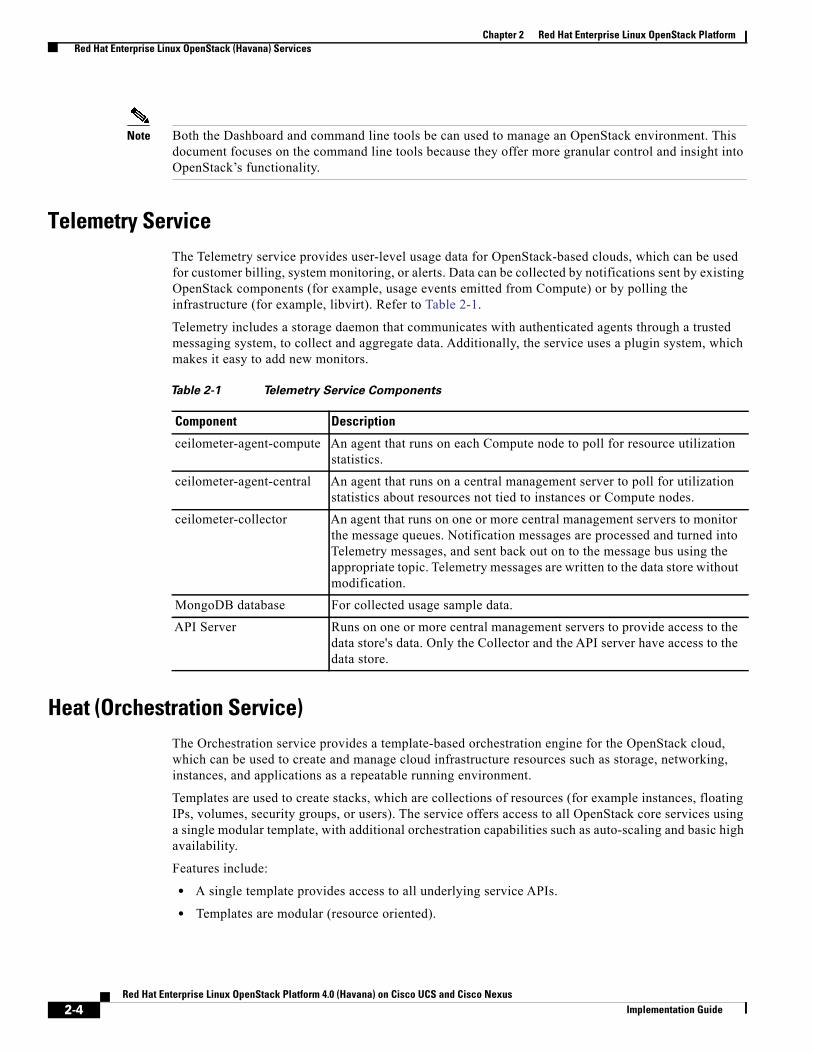
Telemetry ServiceThe Telemetry service provides user-level usage data for OpenStack-based clouds, which can be used for customer billing, system monitoring, or alerts. Data can be collected by notifications sent by existing OpenStack components (for example, usage events emitted from Compute) or by polling the infrastructure (for example, libvirt). Refer to Table 2-1.
Telemetry includes a storage daemon that communicates with authenticated agents through a trusted messaging system, to collect and aggregate data. Additionally, the service uses a plugin system, which makes it easy to add new monitors.
Heat (Orchestration Service)The Orchestration service provides a template-based orchestration engine for the OpenStack cloud, which can be used to create and manage cloud infrastructure resources such as storage, networking, instances, and applications as a repeatable running environment.
Templates are used to create stacks, which are collections of resources (for example instances, floating IPs, volumes, security groups, or users). The service offers access to all OpenStack core services using a single modular template, with additional orchestration capabilities such as auto-scaling and basic high availability.
Features include:
• A single template provides access to all underlying service APIs.
• Templates are modular (resource oriented).
Table 2-1 Telemetry Service Components
Component Description
ceilometer-agent-compute An agent that runs on each Compute node to poll for resource utilization statistics.
ceilometer-agent-central An agent that runs on a central management server to poll for utilization statistics about resources not tied to instances or Compute nodes.
ceilometer-collector An agent that runs on one or more central management servers to monitor the message queues. Notification messages are processed and turned into Telemetry messages, and sent back out on to the message bus using the appropriate topic. Telemetry messages are written to the data store without modification.
MongoDB database For collected usage sample data.
API Server Runs on one or more central management servers to provide access to the data store's data. Only the Collector and the API server have access to the data store.
2-4Red Hat Enterprise Linux OpenStack Platform 4.0 (Havana) on Cisco UCS and Cisco Nexus
Implementation Guide
Chapter 2 Red Hat Enterprise Linux OpenStack PlatformCeph Storage for OpenStack
• Templates can be recursively defined, and therefore reusable (nested stacks). This means that the cloud infrastructure can be defined and reused in a modular way.
• Resource implementation is pluggable, which allows for custom resources.
• Autoscaling functionality (automatically adding or removing resources depending upon usage).
• Basic high availability functionality.
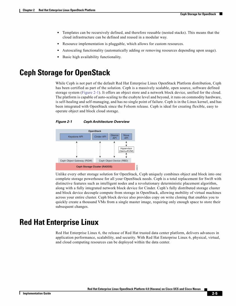
Ceph Storage for OpenStackWhile Ceph is not part of the default Red Hat Enterprise Linux OpenStack Platform distribution, Ceph has been certified as part of the solution. Ceph is a massively scalable, open source, software defined storage system (Figure 2-1). It offers an object store and a network block device, unified for the cloud. The platform is capable of auto-scaling to the exabyte level and beyond, it runs on commodity hardware, is self-healing and self-managing, and has no single point of failure. Ceph is in the Linux kernel, and has been integrated with OpenStack since the Folsom release. Ceph is ideal for creating flexible, easy to operate object and block cloud storage.
Figure 2-1 Ceph Architecture Overview
Unlike every other storage solution for OpenStack, Ceph uniquely combines object and block into one complete storage powerhouse for all your OpenStack needs. Ceph is a total replacement for Swift with distinctive features such as intelligent nodes and a revolutionary deterministic placement algorithm, along with a fully integrated network block device for Cinder. Ceph’s fully distributed storage cluster and block device decouple compute from storage in OpenStack, allowing mobility of virtual machines across your entire cluster. Ceph block device also provides copy on write cloning that enables you to quickly create a thousand VMs from a single master image, requiring only enough space to store their subsequent changes.
Red Hat Enterprise LinuxRed Hat Enterprise Linux 6, the release of Red Hat trusted data center platform, delivers advances in application performance, scalability, and security. With Red Hat Enterprise Linux 6, physical, virtual, and cloud computing resources can be deployed within the data center.
OpenStack
Ceph Storage Cluster (RADOS)
Keystone API GlanceAPI
NovaAPICinder API
2960
70
Ceph Object Gateway (RGW) Ceph Object Device (RBD)
Hypervisor(Qemu/KVM)
2-5Red Hat Enterprise Linux OpenStack Platform 4.0 (Havana) on Cisco UCS and Cisco Nexus
Implementation Guide
Chapter 2 Red Hat Enterprise Linux OpenStack PlatformSupporting Technologies
Supporting TechnologiesThis section describes the supporting technologies used to develop this reference architecture beyond the OpenStack services and core operating system. Supporting technologies include:
• MySQL—A state database resides at the heart of an OpenStack deployment. This SQL database stores most of the build-time and run-time state information for the cloud infrastructure including available instance types, networks, and the state of running instances in the compute fabric. Although OpenStack theoretically supports any SQL-Alchemy compliant database, Red Hat Enterprise Linux OpenStack Platform 4 uses MySQL, a widely used open source database packaged with Red Hat Enterprise Linux 6.
• Qpid —OpenStack services use enterprise messaging to communicate tasks and state changes between clients, service endpoints, service schedulers, and instances. Red Hat Enterprise Linux OpenStack Platform 4 uses Qpid for open source enterprise messaging. Qpid is an Advanced Message Queuing Protocol (AMQP) compliant, cross-platform enterprise messaging system developed for low latency based on an open standard for enterprise messaging. Qpid is released under the Apache open source license.
• KVM—Kernel-based Virtual Machine (KVM) is a full virtualization solution for Linux on x86 and x86_64 hardware containing virtualization extensions for both Intel and AMD processors. It consists of a loadable kernel module that provides the core virtualization infrastructure. Red Hat Enterprise Linux OpenStack Platform Compute uses KVM as its underlying hypervisor to launch and control virtual machine instances.
2-6Red Hat Enterprise Linux OpenStack Platform 4.0 (Havana) on Cisco UCS and Cisco Nexus
Implementation Guide

Red Hat Enterprise Linux OpenStack PImplementation Guide
C H A P T E R 3
Architectural OverviewThis document focuses on the architecture for Red Hat Enterprise Linux OpenStack Platform 4.0 on the UCS using Cisco UCS C-series servers for storage. Cisco UCS C220 M3 servers are used as compute nodes and UCS C240 M3 servers are used as storage nodes. Storage high availability and redundancy are achieved using Ceph storage services on OpenStack. UCS C-series servers are managed by UCSM, which provides ease of infrastructure management and built-in network high availability.
Table 3-1 lists the various hardware and software components, which occupies different tiers of the architecture under test:
Table 3-2 lists the C220M3 server configuration used as storage nodes in this architecture (per serverbasis).
Table 3-1 Hardware and Software Components of the Architecture
Vendor Name Version Description
Cisco Cisco NXOS Nexus Operating System
Cisco Cisco UCS Manager 2.1(3b) Cisco UCS Manager software
Cisco Cisco VIC 1225 2.1(3b) Cisco Virtual Interface Card (adapter) firmware
Cisco Cisco UCS 6248UP Fabric Interconnect
5.0(3)N2(2.11.3b) Cisco UCS fabric interconnect firmware
Cisco Cisco 2232PP Fabric Extender 5.0(3)N2(2.11.3b) Cisco UCS Fabric Extender
Cisco Cisco UCS C220M3 Servers 1.5(3) or later – CIMC
C220M3.1.5.3b - BIOS
Cisco UCS C220M3 Rack Server
Cisco Cisco UCS C240M3 Servers 1.5(3) or later – CIMC
C240M3.1.5.3b - BIOS
Cisco UCS 240M3 Rack Servers
Red Hat Red Hat Enterprise Linux 2.6.32-431.8.1.el6.x86_64 Red Hat Enterprise Linux 6.5 release
Table 3-2 Server Configuration Details
Component Capacity
Memory (RAM) 192 GB (12 X 16 GB DIMM)
3-1latform 4.0 (Havana) on Cisco UCS and Cisco Nexus
Chapter 3 Architectural Overview
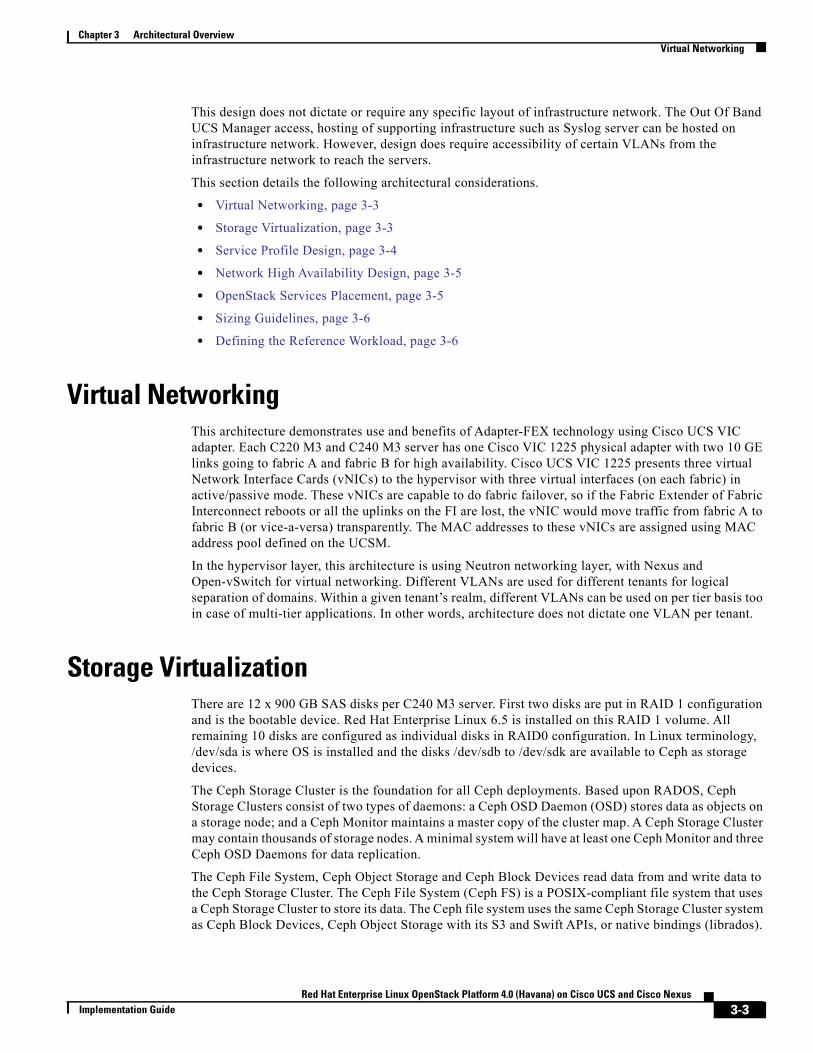
Table 3-3 lists the C240M3 server configuration used as storage nodes in this architecture (per serverbasis).
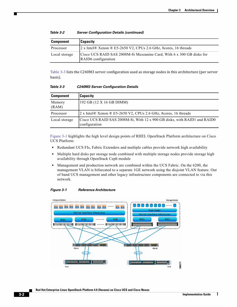
Figure 3-1 highlights the high level design points of RHEL OpenStack Platform architecture on Cisco UCS Platform:
• Redundant UCS FIs, Fabric Extenders and multiple cables provide network high availability
• Multiple hard disks per storage node combined with multiple storage nodes provide storage high availability through OpenStack Ceph module
• Management and production network are combined within the UCS Fabric. On the 6200, the management VLAN is bifurcated to a separate 1GE network using the disjoint VLAN feature. Out of band UCS management and other legacy infrastructure components are connected to via this network.
Figure 3-1 Reference Architecture
Processor 2 x Intel® Xenon ® E5-2650 V2, CPUs 2.6 GHz, 8cores, 16 threads
Local storage Cisco UCS RAID SAS 2008M-8i Mezzanine Card, With 6 x 300 GB disks for RAID6 configuration
Table 3-2 Server Configuration Details (continued)
Component Capacity
Table 3-3 C240M3 Server Configuration Details
Component Capacity
Memory (RAM)
192 GB (12 X 16 GB DIMM)
Processor 2 x Intel® Xenon ® E5-2650 V2, CPUs 2.6 GHz, 8cores, 16 threads
Local storage Cisco UCS RAID SAS 2008M-8i, With 12 x 900 GB disks, with RAID1 and RAID0 configuration
3-2Red Hat Enterprise Linux OpenStack Platform 4.0 (Havana) on Cisco UCS and Cisco Nexus
Implementation Guide
Chapter 3 Architectural OverviewVirtual Networking
This design does not dictate or require any specific layout of infrastructure network. The Out Of Band UCS Manager access, hosting of supporting infrastructure such as Syslog server can be hosted on infrastructure network. However, design does require accessibility of certain VLANs from the infrastructure network to reach the servers.
This section details the following architectural considerations.
• Virtual Networking, page 3-3
• Storage Virtualization, page 3-3
• Service Profile Design, page 3-4
• Network High Availability Design, page 3-5
• OpenStack Services Placement, page 3-5
• Sizing Guidelines, page 3-6
• Defining the Reference Workload, page 3-6
Virtual NetworkingThis architecture demonstrates use and benefits of Adapter-FEX technology using Cisco UCS VIC adapter. Each C220 M3 and C240 M3 server has one Cisco VIC 1225 physical adapter with two 10 GE links going to fabric A and fabric B for high availability. Cisco UCS VIC 1225 presents three virtual Network Interface Cards (vNICs) to the hypervisor with three virtual interfaces (on each fabric) in active/passive mode. These vNICs are capable to do fabric failover, so if the Fabric Extender of Fabric Interconnect reboots or all the uplinks on the FI are lost, the vNIC would move traffic from fabric A to fabric B (or vice-a-versa) transparently. The MAC addresses to these vNICs are assigned using MAC address pool defined on the UCSM.
In the hypervisor layer, this architecture is using Neutron networking layer, with Nexus and Open-vSwitch for virtual networking. Different VLANs are used for different tenants for logical separation of domains. Within a given tenant’s realm, different VLANs can be used on per tier basis too in case of multi-tier applications. In other words, architecture does not dictate one VLAN per tenant.
Storage VirtualizationThere are 12 x 900 GB SAS disks per C240 M3 server. First two disks are put in RAID 1 configuration and is the bootable device. Red Hat Enterprise Linux 6.5 is installed on this RAID 1 volume. All remaining 10 disks are configured as individual disks in RAID0 configuration. In Linux terminology, /dev/sda is where OS is installed and the disks /dev/sdb to /dev/sdk are available to Ceph as storage devices.
The Ceph Storage Cluster is the foundation for all Ceph deployments. Based upon RADOS, Ceph Storage Clusters consist of two types of daemons: a Ceph OSD Daemon (OSD) stores data as objects on a storage node; and a Ceph Monitor maintains a master copy of the cluster map. A Ceph Storage Cluster may contain thousands of storage nodes. A minimal system will have at least one Ceph Monitor and three Ceph OSD Daemons for data replication.
The Ceph File System, Ceph Object Storage and Ceph Block Devices read data from and write data to the Ceph Storage Cluster. The Ceph File System (Ceph FS) is a POSIX-compliant file system that uses a Ceph Storage Cluster to store its data. The Ceph file system uses the same Ceph Storage Cluster system as Ceph Block Devices, Ceph Object Storage with its S3 and Swift APIs, or native bindings (librados).
3-3Red Hat Enterprise Linux OpenStack Platform 4.0 (Havana) on Cisco UCS and Cisco Nexus
Implementation Guide
Chapter 3 Architectural OverviewService Profile Design
Block-based storage interfaces are the most common way to store data with rotating media such as hard disks, CDs, floppy disks, and even traditional 9-track tape. The ubiquity of block device interfaces makes a virtual block device an ideal candidate to interact with a mass data storage system like Ceph.
Ceph block devices are thin-provisioned, re-sizable and store data striped over multiple OSDs in a Ceph cluster. Ceph block devices leverage RADOS capabilities such as snapshotting, replication and consistency. Ceph’s RADOS Block Devices (RBD) interact with OSDs using kernel modules or the librbd library. Ceph’s block devices deliver high performance with infinite scalability to kernel modules, or to KVMs such as Qemu, and cloud-based computing systems like OpenStack and CloudStack that rely on libvirt and Qemu to integrate with Ceph block devices. You can use the same cluster to operate the Ceph RADOS Gateway, the Ceph FS file system, and Ceph block devices simultaneously.
Service Profile DesignThis architecture implements following design steps to truly achieve stateless computing on the servers:
• Service profiles are derived from service profile template for consistency.
• The Red Hat Enterprise Linux host uses following identities in this architecture:
- Host UUID
- Mac Addresses: one per each vNIC on the server
• All of these identifiers are defined in their respective identifier pools and the pool names are referred in the service profile template.
• Server pools are defined with automatic qualification policy and criteria. Rack servers are automatically put in the pool as and when they are fully discovered by UCS Manager. This eliminates the need to manually assign servers to server pool.
• Service profile template is associated to the server pool. This eliminates the need to individually associating service profiles to physical servers.
Given this design and capabilities of UCS and UCS Manager, a new server can be procured within minutes if the scale needs to be increased or if a server needs to be replaced by different hardware. In case, if a server has physical fault (faulty memory, or PSU or fan, for example), using following steps, a new server can be procured within minutes:
• Put the faulty server in maintenance mode. This would move VMs running on fault server to other healthy servers on the cluster.
• Disassociate the service profile from the faulty server and physically remove the server for replacement of faulty hardware (or to completely remove the faulty server).
• Physically install the new server and connect it to the Fabric Extenders. Let the new server be discovered by UCS Manager.
• Associate the service profile to the newly deployed rack server and install Red Hat Enterprise Linux on the local disk.
• The new server would assume the role of the old server with all the identifiers intact.
Given that this architecture assumes deployment of OpenStack from scratch, there is no external image repository available. Once, storage nodes are up and running, you can even host the images. Thus, the architecture achieves the true statelessness of the computing in the data-center. If there are enough identifiers in all the id-pools, and if more servers are attached to UCS system in future, more service profiles can be derived from the service profile template and the private cloud infrastructure can be easily expanded.
3-4Red Hat Enterprise Linux OpenStack Platform 4.0 (Havana) on Cisco UCS and Cisco Nexus
Implementation Guide
Chapter 3 Architectural OverviewNetwork High Availability Design
Network High Availability DesignFollowing are the key aspects of this solution:
• Cisco adapter-FEX technology to introduce virtual NICs to host OS
• Fabric failover feature of adapter-FEX is exploited to provide high availability
• Two 10GE links between FI and FEX provides enough bandwidth over subscription for the given size of cloud. The over subscription can be reduced by adding more 10GE links between FI and FEX if needed by the VMs running on the hosts.
• Three vNICs per host—one for private network within the OpenStack environment and one for the public access of the Linux hosts.
• All the VLANS are divided in two groups—one having their active data network on fabric A and one having their active data network on fabric B. This achieves fair load balancing on two fabrics in addition to the redundancy.
Note Due to neutron bug 1288393, high availability in the ToR layer was removed. Once this bug is resolved, however, redundant links can be re-enabled to make the ToR layer highly available.
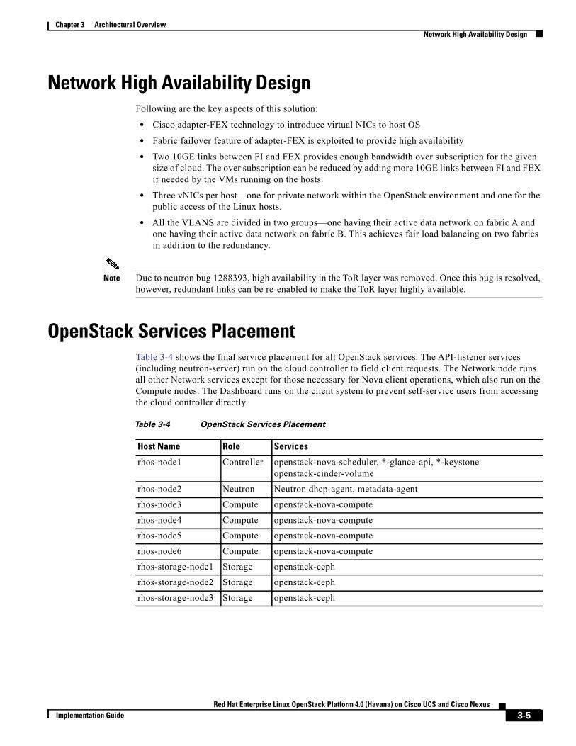
OpenStack Services PlacementTable 3-4 shows the final service placement for all OpenStack services. The API-listener services (including neutron-server) run on the cloud controller to field client requests. The Network node runs all other Network services except for those necessary for Nova client operations, which also run on the Compute nodes. The Dashboard runs on the client system to prevent self-service users from accessing the cloud controller directly.
Table 3-4 OpenStack Services Placement
Host Name Role Services
rhos-node1 Controller openstack-nova-scheduler, *-glance-api, *-keystoneopenstack-cinder-volume
rhos-node2 Neutron Neutron dhcp-agent, metadata-agent
rhos-node3 Compute openstack-nova-compute
rhos-node4 Compute openstack-nova-compute
rhos-node5 Compute openstack-nova-compute
rhos-node6 Compute openstack-nova-compute
rhos-storage-node1 Storage openstack-ceph
rhos-storage-node2 Storage openstack-ceph
rhos-storage-node3 Storage openstack-ceph
3-5Red Hat Enterprise Linux OpenStack Platform 4.0 (Havana) on Cisco UCS and Cisco Nexus
Implementation Guide
Chapter 3 Architectural OverviewSizing Guidelines
Sizing GuidelinesIn any discussion about virtual infrastructures, it is important to first define a reference workload. Not all servers perform the same tasks, and it is impractical to build a reference that takes into account every possible combination of workload characteristics.
Defining the Reference WorkloadTo simplify the discussion, we have defined a representative customer reference workload. By comparing your actual customer usage to this reference workload, you can extrapolate which reference architecture to choose.
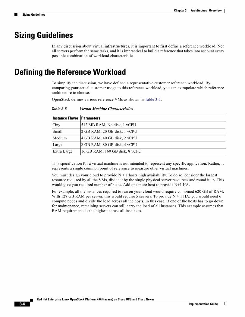
OpenStack defines various reference VMs as shown in Table 3-5.
This specification for a virtual machine is not intended to represent any specific application. Rather, it represents a single common point of reference to measure other virtual machines.
You must design your cloud to provide N + 1 hosts high availability. To do so, consider the largest resource required by all the VMs, divide it by the single physical server resources and round it up. This would give you required number of hosts. Add one more host to provide N+1 HA.
For example, all the instances required to run on your cloud would require combined 620 GB of RAM. With 128 GB RAM per server, this would require 5 servers. To provide N + 1 HA, you would need 6 compute nodes and divide the load across all the hosts. In this case, if one of the hosts has to go down for maintenance, remaining servers can still carry the load of all instances. This example assumes that RAM requirements is the highest across all instances.
Table 3-5 Virtual Machine Characteristics
Instance Flavor Parameters
Tiny 512 MB RAM, No disk, 1 vCPU
Small 2 GB RAM, 20 GB disk, 1 vCPU
Medium 4 GB RAM, 40 GB disk, 2 vCPU
Large 8 GB RAM, 80 GB disk, 4 vCPU
Extra Large 16 GB RAM, 160 GB disk, 8 vCPU
3-6Red Hat Enterprise Linux OpenStack Platform 4.0 (Havana) on Cisco UCS and Cisco Nexus
Implementation Guide
Red Hat Enterprise Linux OpenStack PImplementation Guide
C H A P T E R 4
Configuration GuidelinesThe following sections define the details of configuring RHEL OpenStack Platform architecture on the Cisco UCS platform.
1. Connecting Network Cables, page 4-1
2. Preparing Cisco UCS FI Manager and Configure Manager, page 4-3
3. Cisco Nexus Plug-in for OpenStack Networking, page 4-36
4. Creating OpenStack Setup on Nexus Plug-in Based Topology, page 4-38
5. Configuring the Foreman Server, page 4-46
6. Installation of Controller and Compute and Network Nodes, page 4-59
7. Ink Tank Ceph Installation, page 4-63
8. Known Issues with Ceph, page 4-68
Connecting Network CablesSee the Cisco UCS FI, FEX, and C-series server configuration guide for details on mounting hardware on the rack. Figure 4-1 show three levels of architectural connectivity details covered in this document.
1. Upstream Connectivity (shown in purple)
2. FIs to Fabric Extenders links (shown in blue)
3. Fabric Extenders to C220M3 server links (shown in green)
4-1latform 4.0 (Havana) on Cisco UCS and Cisco Nexus
Chapter 4 Configuration GuidelinesConnecting Network Cables
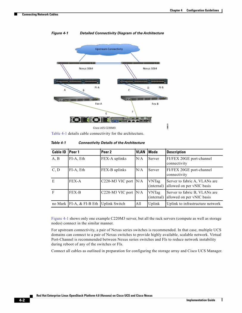
Figure 4-1 Detailed Connectivity Diagram of the Architecture
Table 4-1 details cable connectivity for the architecture.
Figure 4-1 shows only one example C220M3 server, but all the rack servers (compute as well as storage nodes) connect in the similar manner.
For upstream connectivity, a pair of Nexus series switches is recommended. In that case, multiple UCS domains can connect to a pair of Nexus switches to provide highly available, scalable network. Virtual Port-Channel is recommended between Nexus series switches and FIs to reduce network instability during reboot of any of the switches or FIs.
Connect all cables as outlined in preparation for configuring the storage array and Cisco UCS Manager.
Table 4-1 Connectivity Details of the Architecture
Cable ID Peer 1 Peer 2 VLAN Mode Description
A, B FI-A, Eth FEX-A uplinks N/A Server FI/FEX 20GE port-channel connectivity
C, D FI-A, Eth FEX-B uplinks N/A Server FI/FEX 20GE port-channel connectivity
E FEX-A C220-M3 VIC port N/A VNTag (internal)
Server to fabric A, VLANs are allowed on per vNIC basis
F FEX-B C220-M3 VIC port N/A VNTag (internal)
Server to fabric B, VLANs are allowed on per vNIC basis
no Mark FI-A, & FI-B Eth Uplink Switch All Uplink Uplink to infrastructure network
4-2Red Hat Enterprise Linux OpenStack Platform 4.0 (Havana) on Cisco UCS and Cisco Nexus
Implementation Guide
Chapter 4 Configuration GuidelinesPreparing Cisco UCS FI Manager and Configure Manager
Preparing Cisco UCS FI Manager and Configure ManagerConfiguring Cisco UCS FIs and Cisco UCS Manager includes the following procedures.1. Initial Configuration of Cisco UCS FIs, page 4-3
2. Configuration for Server Discovery, page 4-5
3. Upstream/ Global Network Configuration, page 4-8
4. Configure Identifier Pools, page 4-10
5. Configure Server Pool and Qualifying Policy, page 4-14
6. Configure Service Profile Template, page 4-21
7. Instantiate Service Profiles from the Service Profile Template, page 4-33
Initial Configuration of Cisco UCS FIsAt this point of time, the Cisco UCS FIs, FEX, and Blade Servers or Rack Servers must be mounted on the rack and appropriate cables must be connected. Two 100 Mbps Ethernet cables must be connected between two FIs for management pairing. Two redundant power supplies are provided per FI, it is highly recommended that both the power supplies are plugged in, ideally drawing power from two different power strips. Connect mgmt0 interfaces of each FI to the infrastructure network, and put the switch port connected to FI in access mode with access VLAN as management VLAN.
Perform the following procedure to initialize the FI configuration.
Step 1 Attach the RJ-45 serial console cable to the first FI, and connect the other end to the serial port of the laptop.
Step 2 Configure the password for the admin account, fabric ID A, UCS system name, management IP address, subnet mask and default gateway and cluster IP address (or UCS Manager Virtual IP address), as the initial configuration script walks you through the configuration (Figure 4-2).
Step 3 Save the configuration, which will take you to the Cisco UCS Manager CLI login prompt.
4-3Red Hat Enterprise Linux OpenStack Platform 4.0 (Havana) on Cisco UCS and Cisco Nexus
Implementation Guide
Chapter 4 Configuration GuidelinesPreparing Cisco UCS FI Manager and Configure Manager
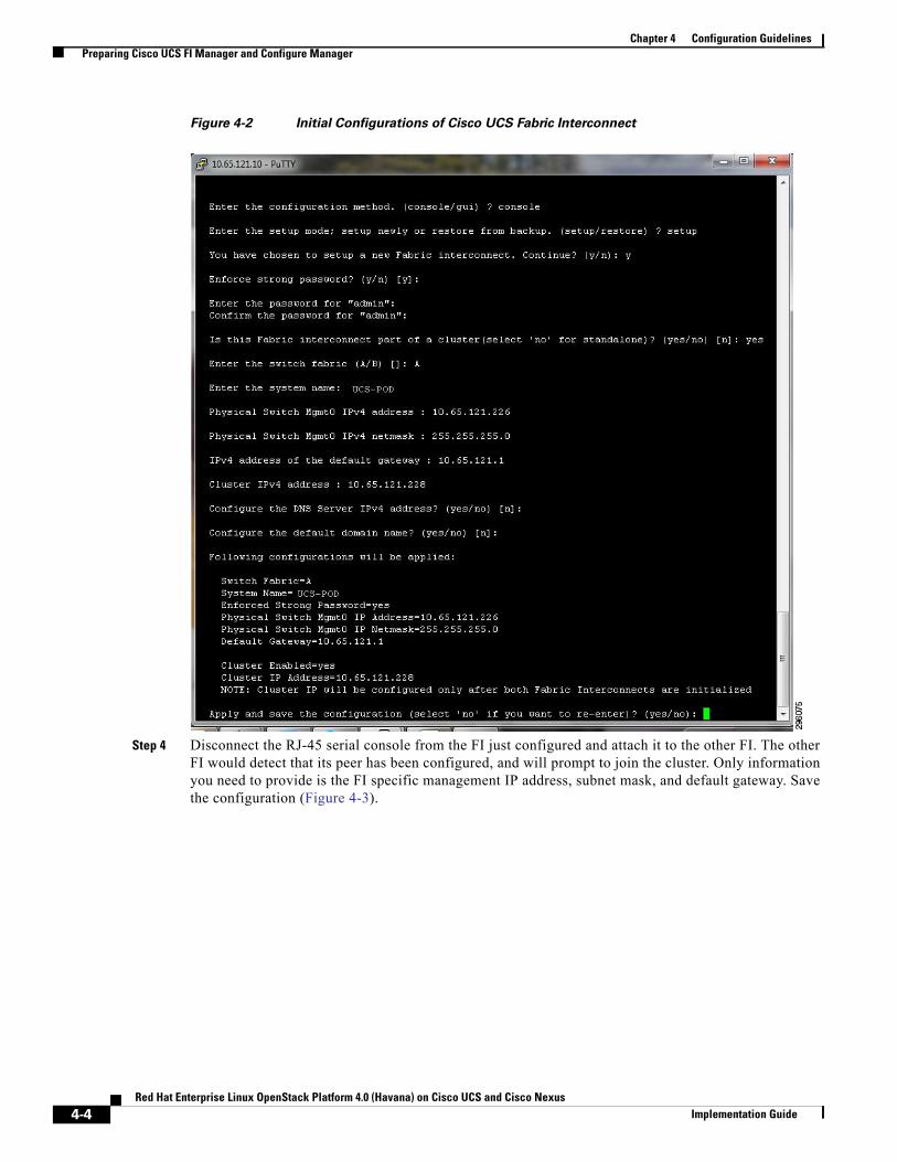
Figure 4-2 Initial Configurations of Cisco UCS Fabric Interconnect
Step 4 Disconnect the RJ-45 serial console from the FI just configured and attach it to the other FI. The other FI would detect that its peer has been configured, and will prompt to join the cluster. Only information you need to provide is the FI specific management IP address, subnet mask, and default gateway. Save the configuration (Figure 4-3).
4-4Red Hat Enterprise Linux OpenStack Platform 4.0 (Havana) on Cisco UCS and Cisco Nexus
Implementation Guide
Chapter 4 Configuration GuidelinesPreparing Cisco UCS FI Manager and Configure Manager
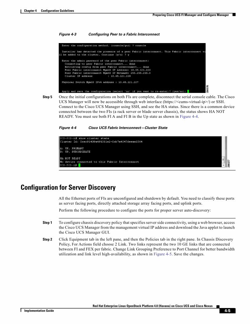
Figure 4-3 Configuring Peer to a Fabric Interconnect
Step 5 Once the initial configurations on both FIs are complete, disconnect the serial console cable. The Cisco UCS Manager will now be accessible through web interface (https://<cums-virtual-ip>/) or SSH. Connect to the Cisco UCS Manager using SSH, and see the HA status. Since there is a common device connected between the two FIs (a rack server or blade server chassis), the status shows HA NOT READY. You must see both FI A and FI B in the Up state as shown in Figure 4-4.
Figure 4-4 Cisco UCS Fabric Interconnect—Cluster State
Configuration for Server DiscoveryAll the Ethernet ports of FIs are unconfigured and shutdown by default. You need to classify these ports as server facing ports, directly attached storage array facing ports, and uplink ports.
Perform the following procedure to configure the ports for proper server auto-discovery:
Step 1 To configure chassis discovery policy that specifies server side connectivity, using a web browser, access the Cisco UCS Manager from the management virtual IP address and download the Java applet to launch the Cisco UCS Manager GUI.
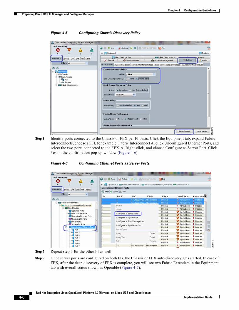
Step 2 Click Equipment tab in the left pane, and then the Policies tab in the right pane. In Chassis Discovery Policy, For Actions field choose 2 Link. Two links represent the two 10 GE links that are connected between FI and FEX per fabric. Change Link Grouping Preference to Port Channel for better bandwidth utilization and link level high-availability, as shown in Figure 4-5. Save the changes.
4-5Red Hat Enterprise Linux OpenStack Platform 4.0 (Havana) on Cisco UCS and Cisco Nexus
Implementation Guide
Chapter 4 Configuration GuidelinesPreparing Cisco UCS FI Manager and Configure Manager
Figure 4-5 Configuring Chassis Discovery Policy
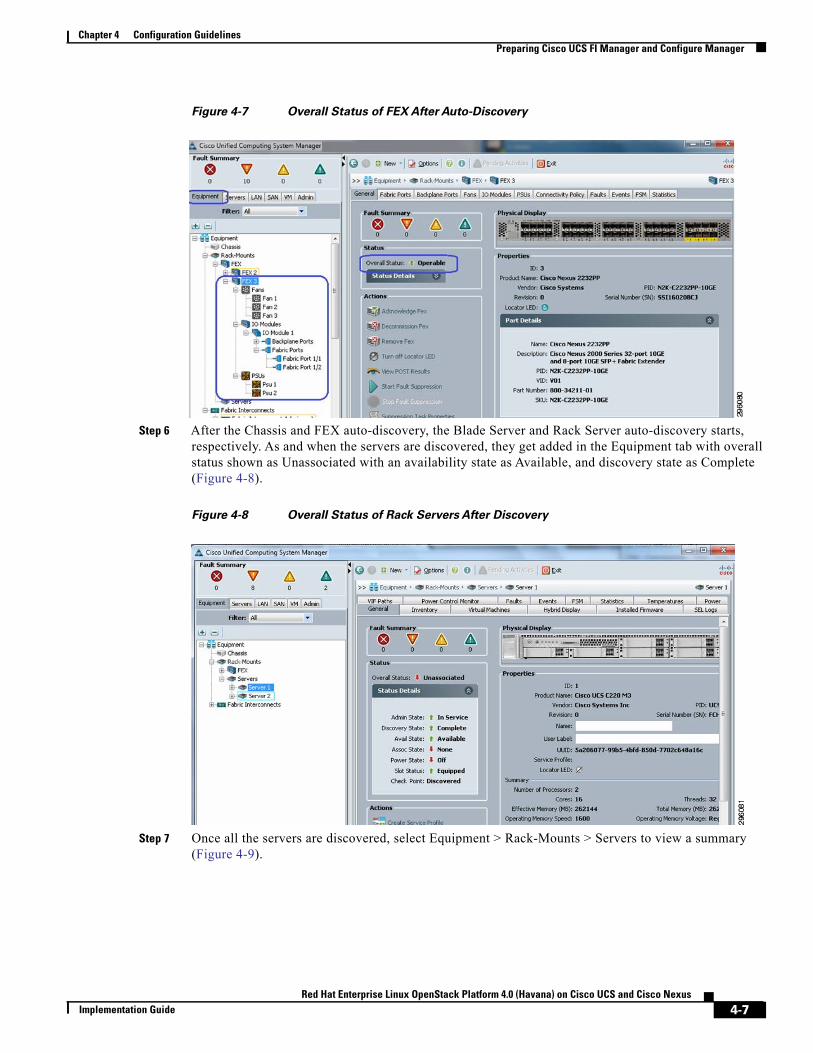
Step 3 Identify ports connected to the Chassis or FEX per FI basis. Click the Equipment tab, expand Fabric Interconnects, choose an FI, for example, Fabric Interconnect A, click Unconfigured Ethernet Ports, and select the two ports connected to the FEX-A. Right-click, and choose Configure as Server Port. Click Yes on the confirmation pop-up window (Figure 4-6).
Figure 4-6 Configuring Ethernet Ports as Server Ports
Step 4 Repeat step 3 for the other FI as well.
Step 5 Once server ports are configured on both FIs, the Chassis or FEX auto-discovery gets started. In case of FEX, after the deep discovery of FEX is complete, you will see two Fabric Extenders in the Equipment tab with overall status shown as Operable (Figure 4-7).
4-6Red Hat Enterprise Linux OpenStack Platform 4.0 (Havana) on Cisco UCS and Cisco Nexus
Implementation Guide
Chapter 4 Configuration GuidelinesPreparing Cisco UCS FI Manager and Configure Manager
Figure 4-7 Overall Status of FEX After Auto-Discovery
Step 6 After the Chassis and FEX auto-discovery, the Blade Server and Rack Server auto-discovery starts, respectively. As and when the servers are discovered, they get added in the Equipment tab with overall status shown as Unassociated with an availability state as Available, and discovery state as Complete (Figure 4-8).
Figure 4-8 Overall Status of Rack Servers After Discovery
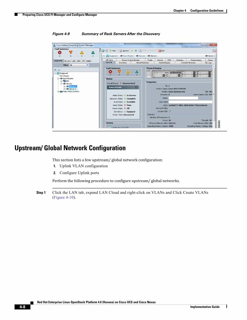
Step 7 Once all the servers are discovered, select Equipment > Rack-Mounts > Servers to view a summary (Figure 4-9).
4-7Red Hat Enterprise Linux OpenStack Platform 4.0 (Havana) on Cisco UCS and Cisco Nexus
Implementation Guide
Chapter 4 Configuration GuidelinesPreparing Cisco UCS FI Manager and Configure Manager
Figure 4-9 Summary of Rack Servers After the Discovery
Upstream/ Global Network Configuration
This section lists a few upstream/ global network configuration:1. Uplink VLAN configuration
2. Configure Uplink ports
Perform the following procedure to configure upstream/ global networks.
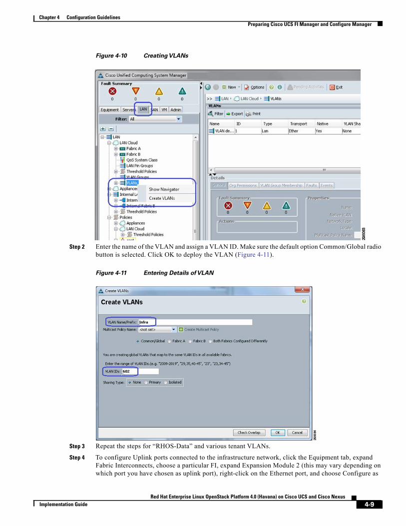
Step 1 Click the LAN tab, expand LAN Cloud and right-click on VLANs and Click Create VLANs (Figure 4-10).
4-8Red Hat Enterprise Linux OpenStack Platform 4.0 (Havana) on Cisco UCS and Cisco Nexus
Implementation Guide
Chapter 4 Configuration GuidelinesPreparing Cisco UCS FI Manager and Configure Manager
Figure 4-10 Creating VLANs
Step 2 Enter the name of the VLAN and assign a VLAN ID. Make sure the default option Common/Global radio button is selected. Click OK to deploy the VLAN (Figure 4-11).
Figure 4-11 Entering Details of VLAN
Step 3 Repeat the steps for “RHOS-Data” and various tenant VLANs.
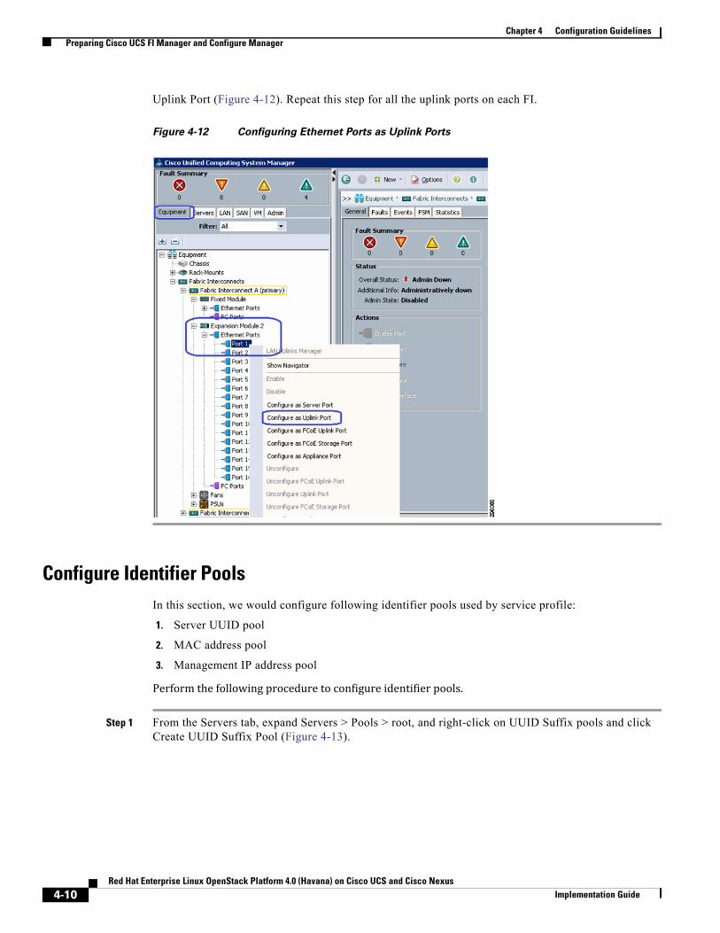
Step 4 To configure Uplink ports connected to the infrastructure network, click the Equipment tab, expand Fabric Interconnects, choose a particular FI, expand Expansion Module 2 (this may vary depending on which port you have chosen as uplink port), right-click on the Ethernet port, and choose Configure as
4-9Red Hat Enterprise Linux OpenStack Platform 4.0 (Havana) on Cisco UCS and Cisco Nexus
Implementation Guide
Chapter 4 Configuration GuidelinesPreparing Cisco UCS FI Manager and Configure Manager
Uplink Port (Figure 4-12). Repeat this step for all the uplink ports on each FI.
Figure 4-12 Configuring Ethernet Ports as Uplink Ports
Configure Identifier PoolsIn this section, we would configure following identifier pools used by service profile:
1. Server UUID pool
2. MAC address pool
3. Management IP address pool
Perform the following procedure to configure identifier pools.
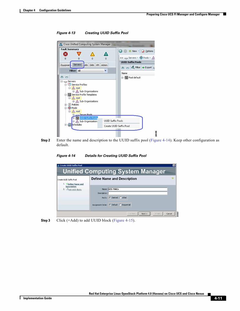
Step 1 From the Servers tab, expand Servers > Pools > root, and right-click on UUID Suffix pools and click Create UUID Suffix Pool (Figure 4-13).
4-10Red Hat Enterprise Linux OpenStack Platform 4.0 (Havana) on Cisco UCS and Cisco Nexus
Implementation Guide
Chapter 4 Configuration GuidelinesPreparing Cisco UCS FI Manager and Configure Manager
Figure 4-13 Creating UUID Suffix Pool
Step 2 Enter the name and description to the UUID suffix pool (Figure 4-14). Keep other configuration as default.
Figure 4-14 Details for Creating UUID Suffix Pool
Step 3 Click (+Add) to add UUID block (Figure 4-15).
4-11Red Hat Enterprise Linux OpenStack Platform 4.0 (Havana) on Cisco UCS and Cisco Nexus
Implementation Guide
Chapter 4 Configuration GuidelinesPreparing Cisco UCS FI Manager and Configure Manager
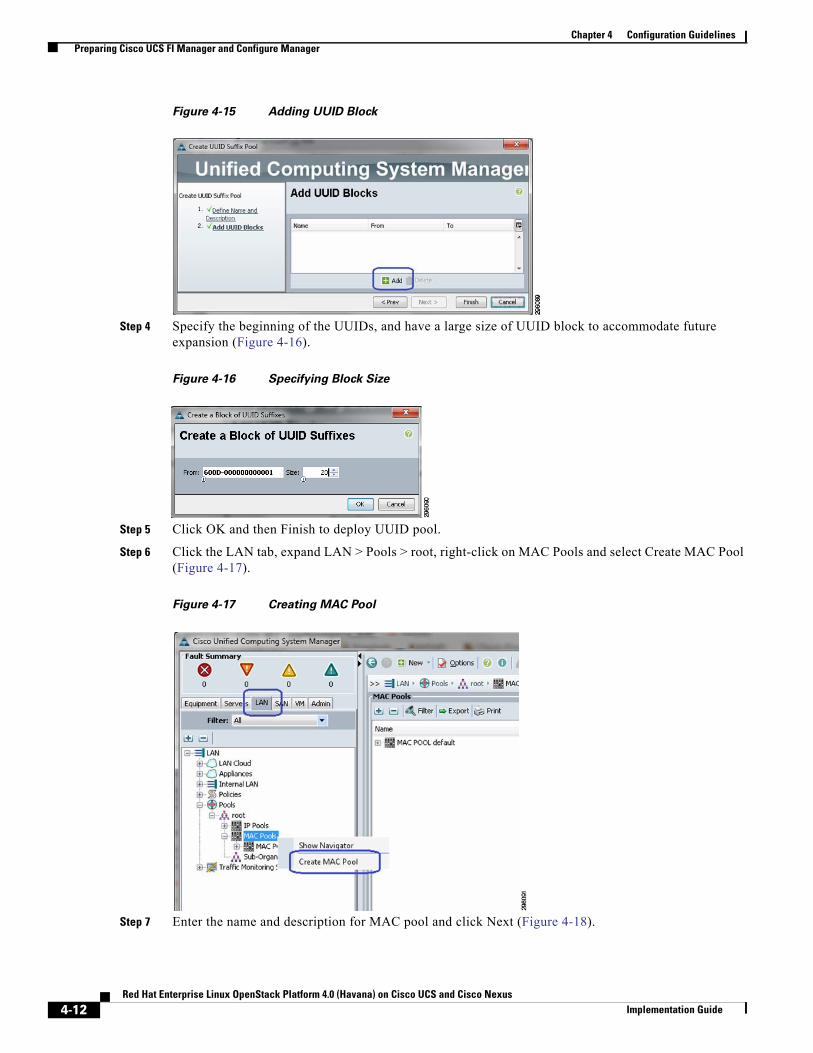
Figure 4-15 Adding UUID Block
Step 4 Specify the beginning of the UUIDs, and have a large size of UUID block to accommodate future expansion (Figure 4-16).
Figure 4-16 Specifying Block Size
Step 5 Click OK and then Finish to deploy UUID pool.
Step 6 Click the LAN tab, expand LAN > Pools > root, right-click on MAC Pools and select Create MAC Pool (Figure 4-17).
Figure 4-17 Creating MAC Pool
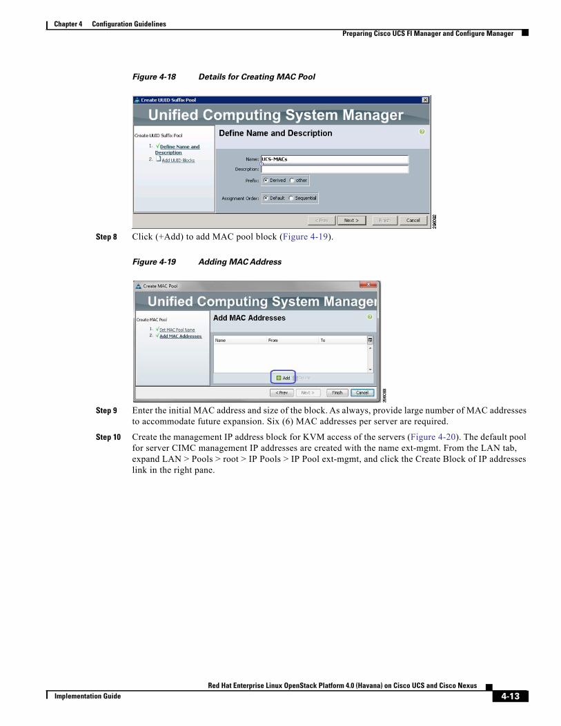
Step 7 Enter the name and description for MAC pool and click Next (Figure 4-18).
4-12Red Hat Enterprise Linux OpenStack Platform 4.0 (Havana) on Cisco UCS and Cisco Nexus
Implementation Guide
Chapter 4 Configuration GuidelinesPreparing Cisco UCS FI Manager and Configure Manager
Figure 4-18 Details for Creating MAC Pool
Step 8 Click (+Add) to add MAC pool block (Figure 4-19).
Figure 4-19 Adding MAC Address
Step 9 Enter the initial MAC address and size of the block. As always, provide large number of MAC addresses to accommodate future expansion. Six (6) MAC addresses per server are required.
Step 10 Create the management IP address block for KVM access of the servers (Figure 4-20). The default pool for server CIMC management IP addresses are created with the name ext-mgmt. From the LAN tab, expand LAN > Pools > root > IP Pools > IP Pool ext-mgmt, and click the Create Block of IP addresses link in the right pane.
4-13Red Hat Enterprise Linux OpenStack Platform 4.0 (Havana) on Cisco UCS and Cisco Nexus
Implementation Guide
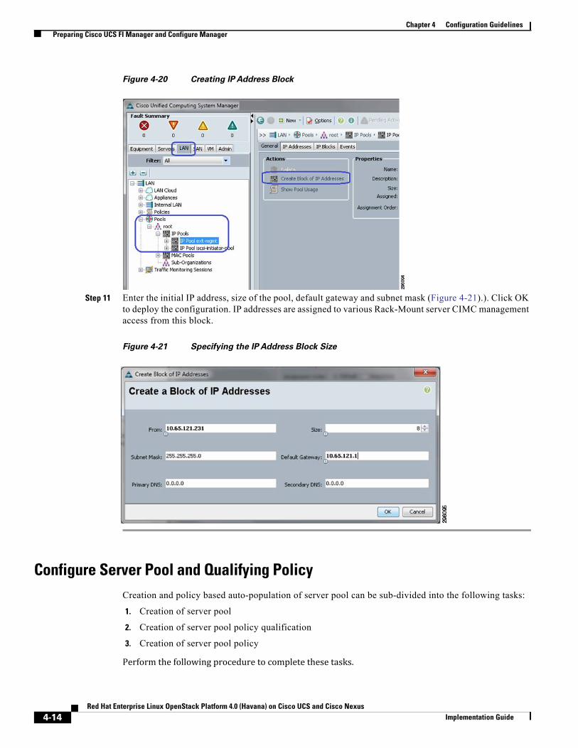
Chapter 4 Configuration GuidelinesPreparing Cisco UCS FI Manager and Configure Manager
Figure 4-20 Creating IP Address Block
Step 11 Enter the initial IP address, size of the pool, default gateway and subnet mask (Figure 4-21).). Click OK to deploy the configuration. IP addresses are assigned to various Rack-Mount server CIMC management access from this block.
Figure 4-21 Specifying the IP Address Block Size
Configure Server Pool and Qualifying PolicyCreation and policy based auto-population of server pool can be sub-divided into the following tasks:
1. Creation of server pool
2. Creation of server pool policy qualification
3. Creation of server pool policy
Perform the following procedure to complete these tasks.
4-14Red Hat Enterprise Linux OpenStack Platform 4.0 (Havana) on Cisco UCS and Cisco Nexus
Implementation Guide

Chapter 4 Configuration GuidelinesPreparing Cisco UCS FI Manager and Configure Manager
Step 1 From the Servers tab, expand Servers > Pools > root, right-click on Server Pools and choose Create Server Pool (Figure 4-22).
Figure 4-22 Creating Server Pools
Step 2 Enter the name of the server pool in the Name field, and click Next (Figure 4-23).
Figure 4-23 Entering Details in the Create Server Pool Wizard
Step 3 Click Finish to create the empty server pool. We would add the compute resources to this pool dynamically, based on policy (Figure 4-24).
4-15Red Hat Enterprise Linux OpenStack Platform 4.0 (Havana) on Cisco UCS and Cisco Nexus
Implementation Guide
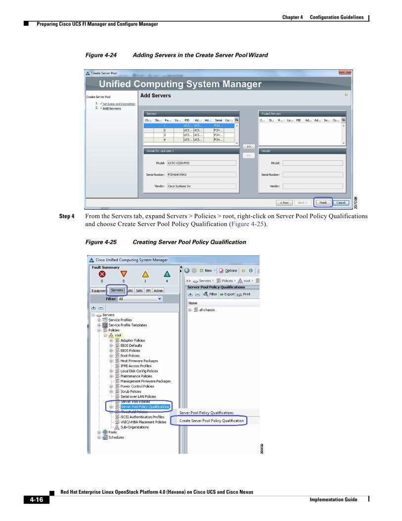
Chapter 4 Configuration GuidelinesPreparing Cisco UCS FI Manager and Configure Manager
Figure 4-24 Adding Servers in the Create Server Pool Wizard
Step 4 From the Servers tab, expand Servers > Policies > root, right-click on Server Pool Policy Qualifications and choose Create Server Pool Policy Qualification (Figure 4-25).
Figure 4-25 Creating Server Pool Policy Qualification
4-16Red Hat Enterprise Linux OpenStack Platform 4.0 (Havana) on Cisco UCS and Cisco Nexus
Implementation Guide
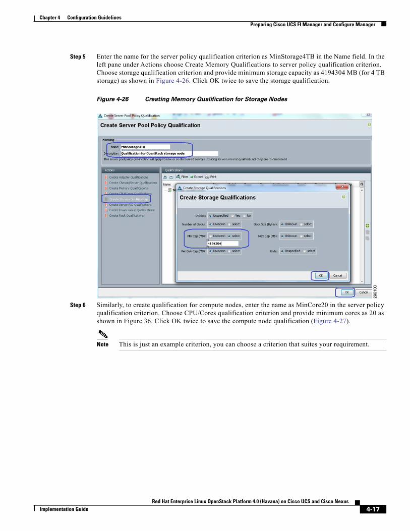
Chapter 4 Configuration GuidelinesPreparing Cisco UCS FI Manager and Configure Manager
Step 5 Enter the name for the server policy qualification criterion as MinStorage4TB in the Name field. In the left pane under Actions choose Create Memory Qualifications to server policy qualification criterion. Choose storage qualification criterion and provide minimum storage capacity as 4194304 MB (for 4 TB storage) as shown in Figure 4-26. Click OK twice to save the storage qualification.
Figure 4-26 Creating Memory Qualification for Storage Nodes
Step 6 Similarly, to create qualification for compute nodes, enter the name as MinCore20 in the server policy qualification criterion. Choose CPU/Cores qualification criterion and provide minimum cores as 20 as shown in Figure 36. Click OK twice to save the compute node qualification (Figure 4-27).
Note This is just an example criterion, you can choose a criterion that suites your requirement.
4-17Red Hat Enterprise Linux OpenStack Platform 4.0 (Havana) on Cisco UCS and Cisco Nexus
Implementation Guide
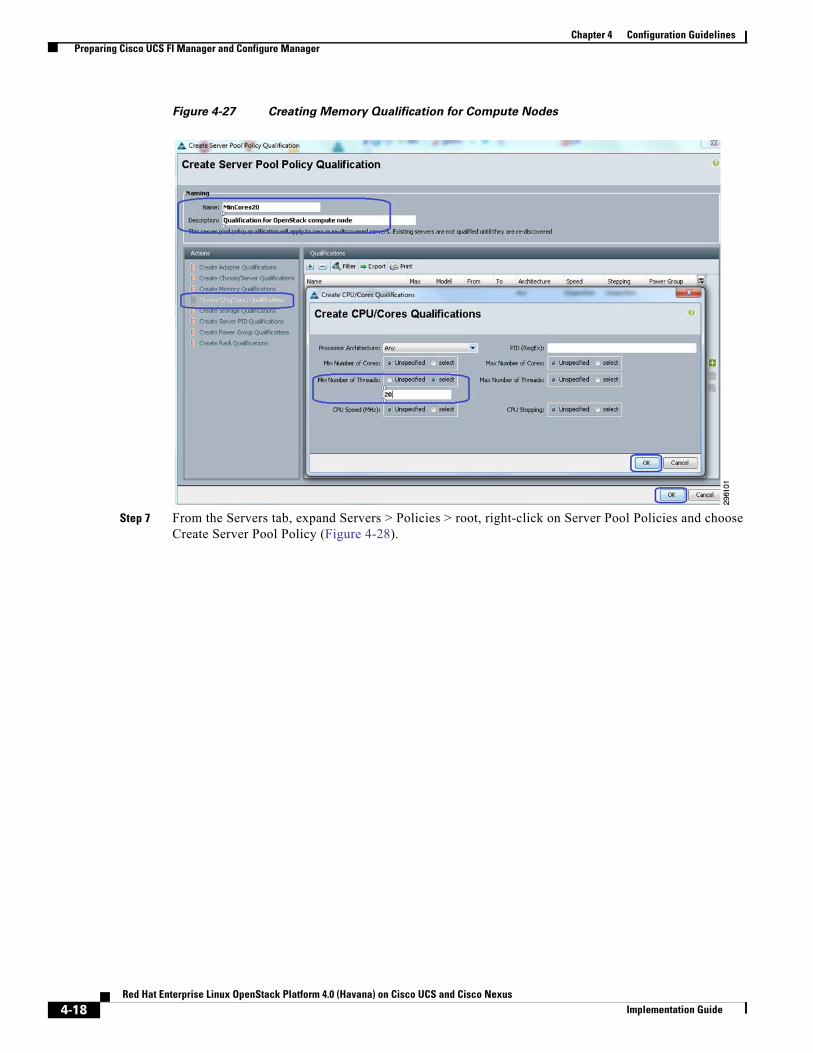
Chapter 4 Configuration GuidelinesPreparing Cisco UCS FI Manager and Configure Manager
Figure 4-27 Creating Memory Qualification for Compute Nodes
Step 7 From the Servers tab, expand Servers > Policies > root, right-click on Server Pool Policies and choose Create Server Pool Policy (Figure 4-28).
4-18Red Hat Enterprise Linux OpenStack Platform 4.0 (Havana) on Cisco UCS and Cisco Nexus
Implementation Guide
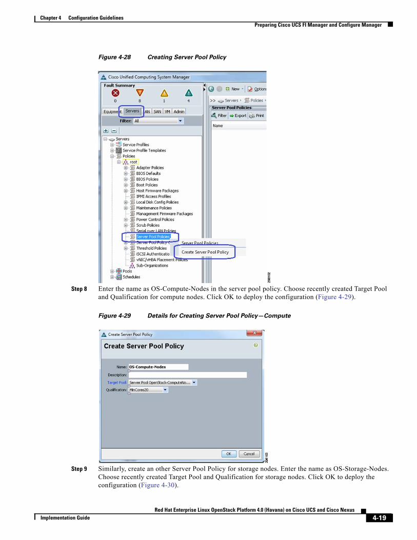
Chapter 4 Configuration GuidelinesPreparing Cisco UCS FI Manager and Configure Manager
Figure 4-28 Creating Server Pool Policy
Step 8 Enter the name as OS-Compute-Nodes in the server pool policy. Choose recently created Target Pool and Qualification for compute nodes. Click OK to deploy the configuration (Figure 4-29).
Figure 4-29 Details for Creating Server Pool Policy—Compute
Step 9 Similarly, create an other Server Pool Policy for storage nodes. Enter the name as OS-Storage-Nodes. Choose recently created Target Pool and Qualification for storage nodes. Click OK to deploy the configuration (Figure 4-30).
4-19Red Hat Enterprise Linux OpenStack Platform 4.0 (Havana) on Cisco UCS and Cisco Nexus
Implementation Guide
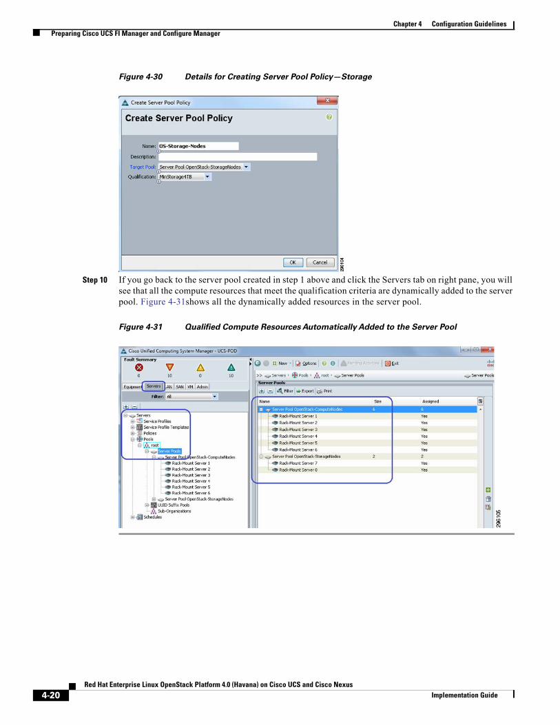
Chapter 4 Configuration GuidelinesPreparing Cisco UCS FI Manager and Configure Manager
Figure 4-30 Details for Creating Server Pool Policy—Storage
Step 10 If you go back to the server pool created in step 1 above and click the Servers tab on right pane, you will see that all the compute resources that meet the qualification criteria are dynamically added to the server pool. Figure 4-31shows all the dynamically added resources in the server pool.
Figure 4-31 Qualified Compute Resources Automatically Added to the Server Pool
4-20Red Hat Enterprise Linux OpenStack Platform 4.0 (Havana) on Cisco UCS and Cisco Nexus
Implementation Guide
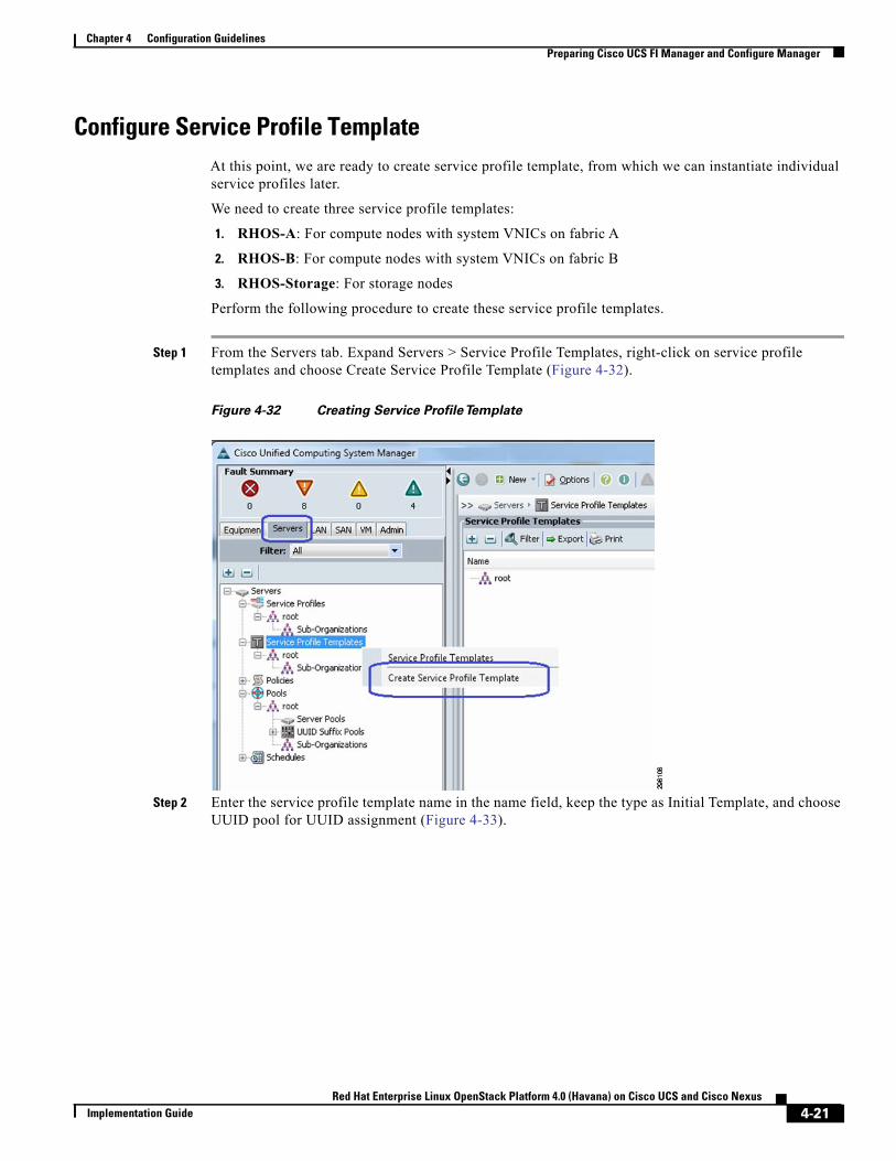
Chapter 4 Configuration GuidelinesPreparing Cisco UCS FI Manager and Configure Manager
Configure Service Profile TemplateAt this point, we are ready to create service profile template, from which we can instantiate individual service profiles later.
We need to create three service profile templates:
1. RHOS-A: For compute nodes with system VNICs on fabric A
2. RHOS-B: For compute nodes with system VNICs on fabric B
3. RHOS-Storage: For storage nodes
Perform the following procedure to create these service profile templates.
Step 1 From the Servers tab. Expand Servers > Service Profile Templates, right-click on service profile templates and choose Create Service Profile Template (Figure 4-32).
Figure 4-32 Creating Service ProfileTemplate
Step 2 Enter the service profile template name in the name field, keep the type as Initial Template, and choose UUID pool for UUID assignment (Figure 4-33).
4-21Red Hat Enterprise Linux OpenStack Platform 4.0 (Havana) on Cisco UCS and Cisco Nexus
Implementation Guide
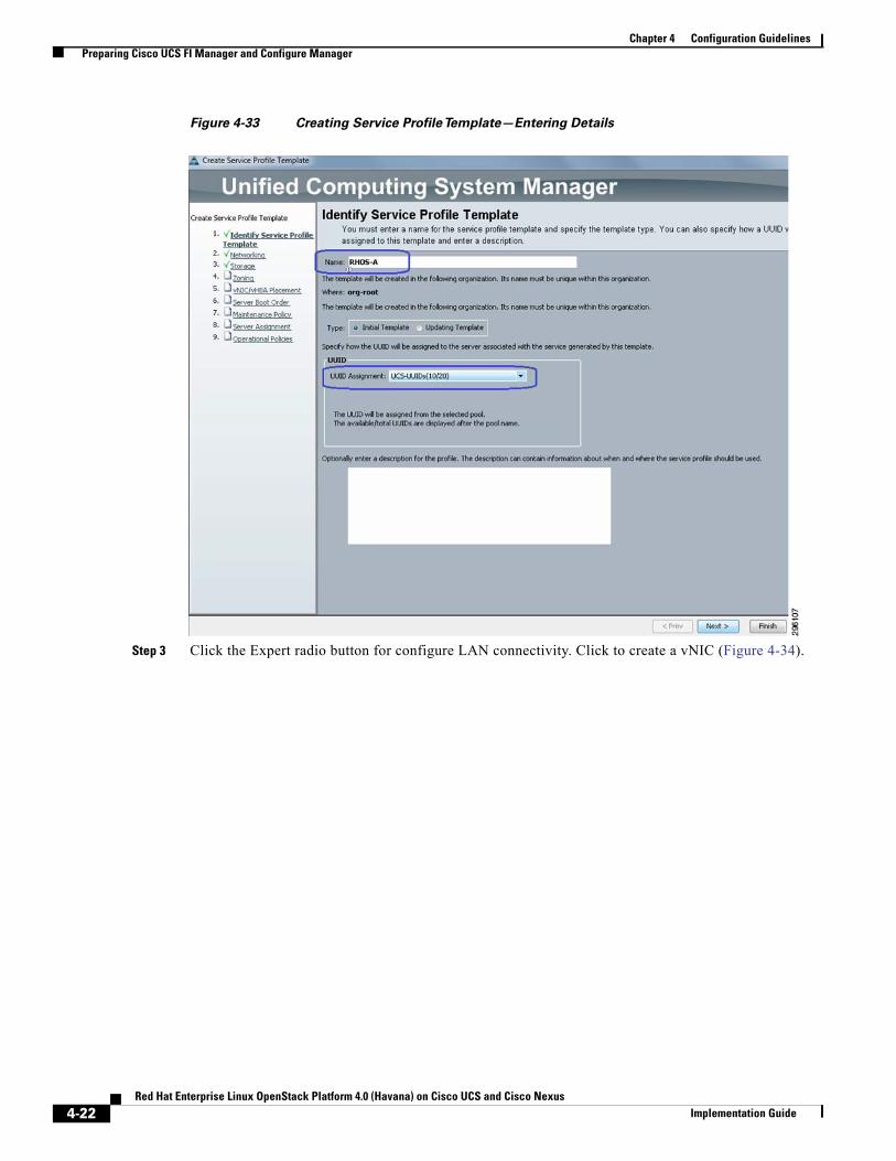
Chapter 4 Configuration GuidelinesPreparing Cisco UCS FI Manager and Configure Manager
Figure 4-33 Creating Service ProfileTemplate—Entering Details
Step 3 Click the Expert radio button for configure LAN connectivity. Click to create a vNIC (Figure 4-34).
4-22Red Hat Enterprise Linux OpenStack Platform 4.0 (Havana) on Cisco UCS and Cisco Nexus
Implementation Guide
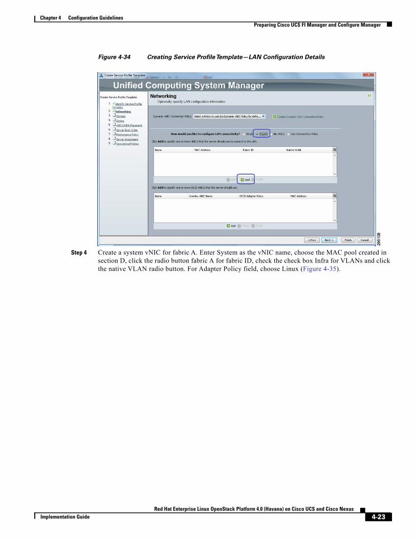
Chapter 4 Configuration GuidelinesPreparing Cisco UCS FI Manager and Configure Manager
Figure 4-34 Creating Service ProfileTemplate—LAN Configuration Details
Step 4 Create a system vNIC for fabric A. Enter System as the vNIC name, choose the MAC pool created in section D, click the radio button fabric A for fabric ID, check the check box Infra for VLANs and click the native VLAN radio button. For Adapter Policy field, choose Linux (Figure 4-35).
4-23Red Hat Enterprise Linux OpenStack Platform 4.0 (Havana) on Cisco UCS and Cisco Nexus
Implementation Guide
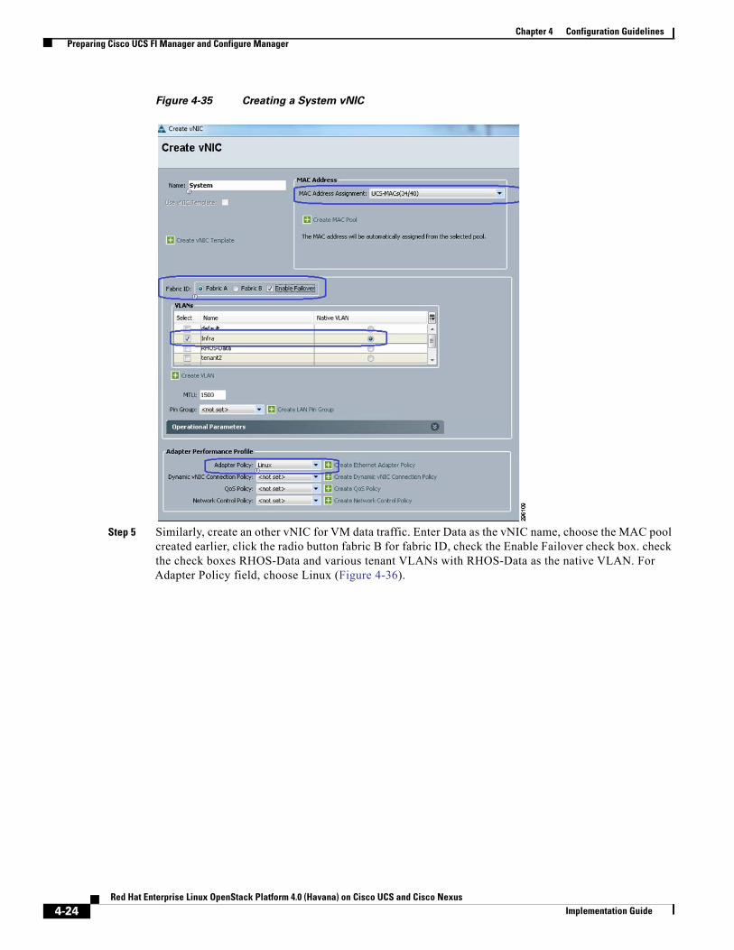
Chapter 4 Configuration GuidelinesPreparing Cisco UCS FI Manager and Configure Manager
Figure 4-35 Creating a System vNIC
Step 5 Similarly, create an other vNIC for VM data traffic. Enter Data as the vNIC name, choose the MAC pool created earlier, click the radio button fabric B for fabric ID, check the Enable Failover check box. check the check boxes RHOS-Data and various tenant VLANs with RHOS-Data as the native VLAN. For Adapter Policy field, choose Linux (Figure 4-36).
4-24Red Hat Enterprise Linux OpenStack Platform 4.0 (Havana) on Cisco UCS and Cisco Nexus
Implementation Guide
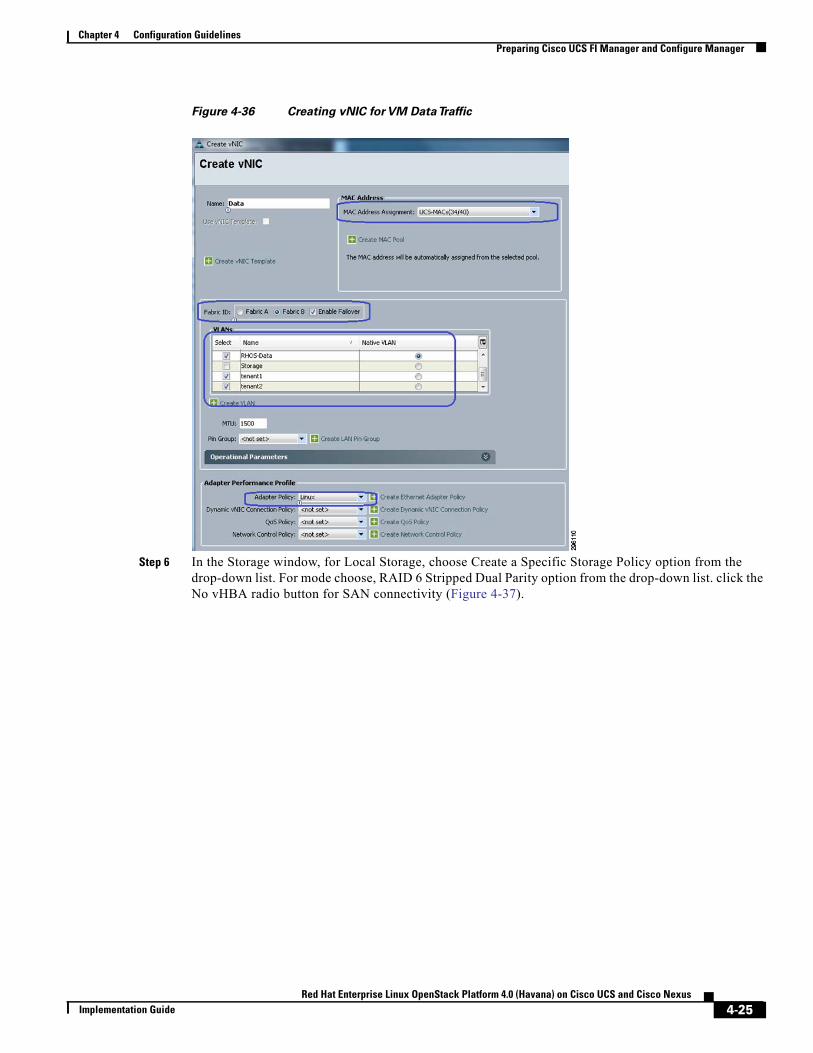
Chapter 4 Configuration GuidelinesPreparing Cisco UCS FI Manager and Configure Manager
Figure 4-36 Creating vNIC for VM DataTraffic
Step 6 In the Storage window, for Local Storage, choose Create a Specific Storage Policy option from the drop-down list. For mode choose, RAID 6 Stripped Dual Parity option from the drop-down list. click the No vHBA radio button for SAN connectivity (Figure 4-37).
4-25Red Hat Enterprise Linux OpenStack Platform 4.0 (Havana) on Cisco UCS and Cisco Nexus
Implementation Guide
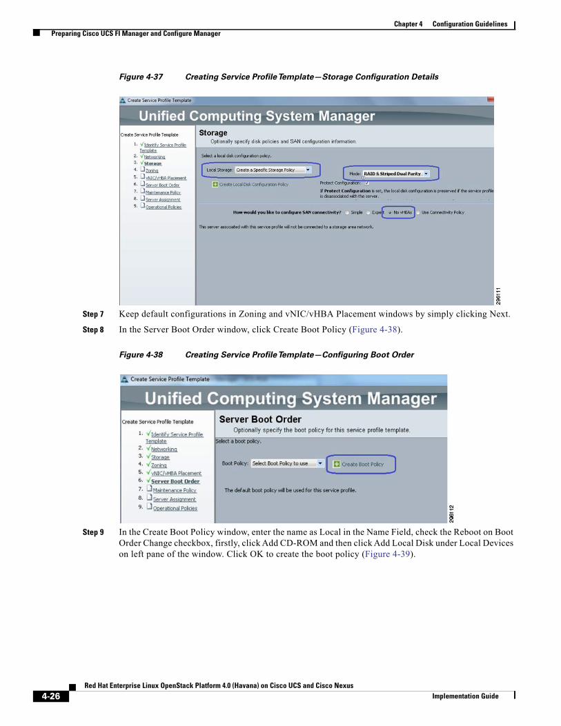
Chapter 4 Configuration GuidelinesPreparing Cisco UCS FI Manager and Configure Manager
Figure 4-37 Creating Service ProfileTemplate—Storage Configuration Details
Step 7 Keep default configurations in Zoning and vNIC/vHBA Placement windows by simply clicking Next.
Step 8 In the Server Boot Order window, click Create Boot Policy (Figure 4-38).
Figure 4-38 Creating Service ProfileTemplate—Configuring Boot Order
Step 9 In the Create Boot Policy window, enter the name as Local in the Name Field, check the Reboot on Boot Order Change checkbox, firstly, click Add CD-ROM and then click Add Local Disk under Local Devices on left pane of the window. Click OK to create the boot policy (Figure 4-39).
4-26Red Hat Enterprise Linux OpenStack Platform 4.0 (Havana) on Cisco UCS and Cisco Nexus
Implementation Guide
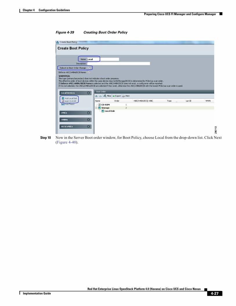
Chapter 4 Configuration GuidelinesPreparing Cisco UCS FI Manager and Configure Manager
Figure 4-39 Creating Boot Order Policy
Step 10 Now in the Server Boot order window, for Boot Policy, choose Local from the drop-down list. Click Next (Figure 4-40).
4-27Red Hat Enterprise Linux OpenStack Platform 4.0 (Havana) on Cisco UCS and Cisco Nexus
Implementation Guide
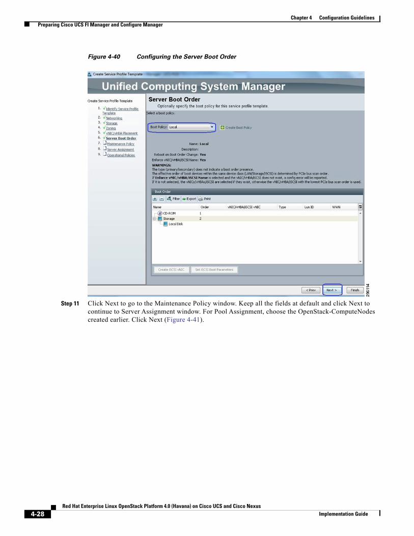
Chapter 4 Configuration GuidelinesPreparing Cisco UCS FI Manager and Configure Manager
Figure 4-40 Configuring the Server Boot Order
Step 11 Click Next to go to the Maintenance Policy window. Keep all the fields at default and click Next to continue to Server Assignment window. For Pool Assignment, choose the OpenStack-ComputeNodes created earlier. Click Next (Figure 4-41).
4-28Red Hat Enterprise Linux OpenStack Platform 4.0 (Havana) on Cisco UCS and Cisco Nexus
Implementation Guide
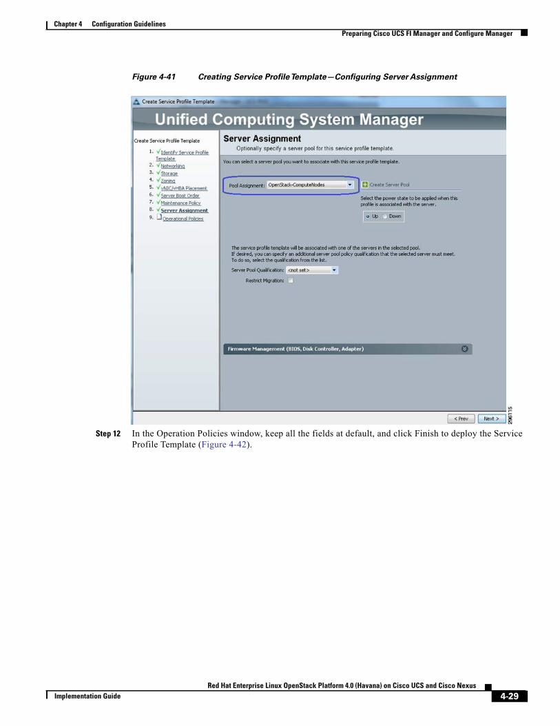
Chapter 4 Configuration GuidelinesPreparing Cisco UCS FI Manager and Configure Manager
Figure 4-41 Creating Service ProfileTemplate—Configuring Server Assignment
Step 12 In the Operation Policies window, keep all the fields at default, and click Finish to deploy the Service Profile Template (Figure 4-42).
4-29Red Hat Enterprise Linux OpenStack Platform 4.0 (Havana) on Cisco UCS and Cisco Nexus
Implementation Guide
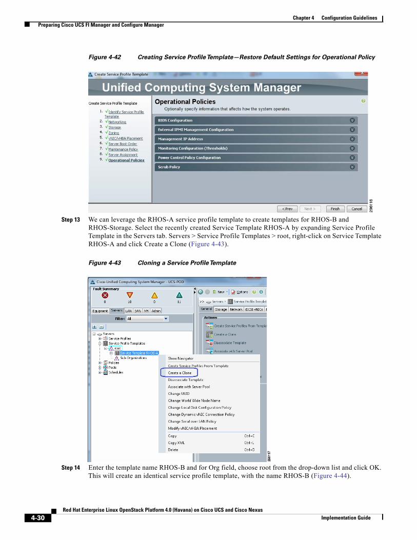
Chapter 4 Configuration GuidelinesPreparing Cisco UCS FI Manager and Configure Manager
Figure 4-42 Creating Service ProfileTemplate—Restore Default Settings for Operational Policy
Step 13 We can leverage the RHOS-A service profile template to create templates for RHOS-B and RHOS-Storage. Select the recently created Service Template RHOS-A by expanding Service Profile Template in the Servers tab. Servers > Service Profile Templates > root, right-click on Service Template RHOS-A and click Create a Clone (Figure 4-43).
Figure 4-43 Cloning a Service ProfileTemplate
Step 14 Enter the template name RHOS-B and for Org field, choose root from the drop-down list and click OK. This will create an identical service profile template, with the name RHOS-B (Figure 4-44).
4-30Red Hat Enterprise Linux OpenStack Platform 4.0 (Havana) on Cisco UCS and Cisco Nexus
Implementation Guide
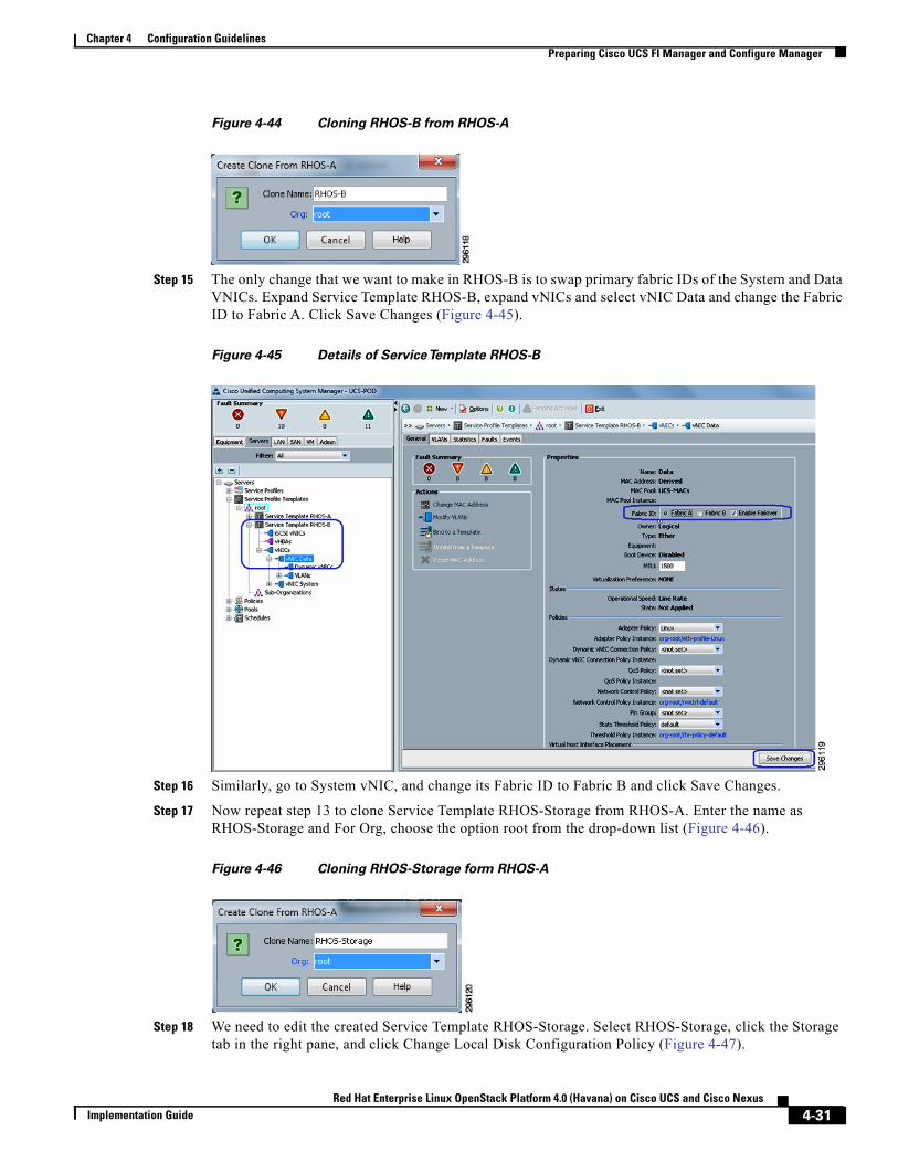
Chapter 4 Configuration GuidelinesPreparing Cisco UCS FI Manager and Configure Manager
Figure 4-44 Cloning RHOS-B from RHOS-A
Step 15 The only change that we want to make in RHOS-B is to swap primary fabric IDs of the System and Data VNICs. Expand Service Template RHOS-B, expand vNICs and select vNIC Data and change the Fabric ID to Fabric A. Click Save Changes (Figure 4-45).
Figure 4-45 Details of ServiceTemplate RHOS-B
Step 16 Similarly, go to System vNIC, and change its Fabric ID to Fabric B and click Save Changes.
Step 17 Now repeat step 13 to clone Service Template RHOS-Storage from RHOS-A. Enter the name as RHOS-Storage and For Org, choose the option root from the drop-down list (Figure 4-46).
Figure 4-46 Cloning RHOS-Storage form RHOS-A
Step 18 We need to edit the created Service Template RHOS-Storage. Select RHOS-Storage, click the Storage tab in the right pane, and click Change Local Disk Configuration Policy (Figure 4-47).
4-31Red Hat Enterprise Linux OpenStack Platform 4.0 (Havana) on Cisco UCS and Cisco Nexus
Implementation Guide
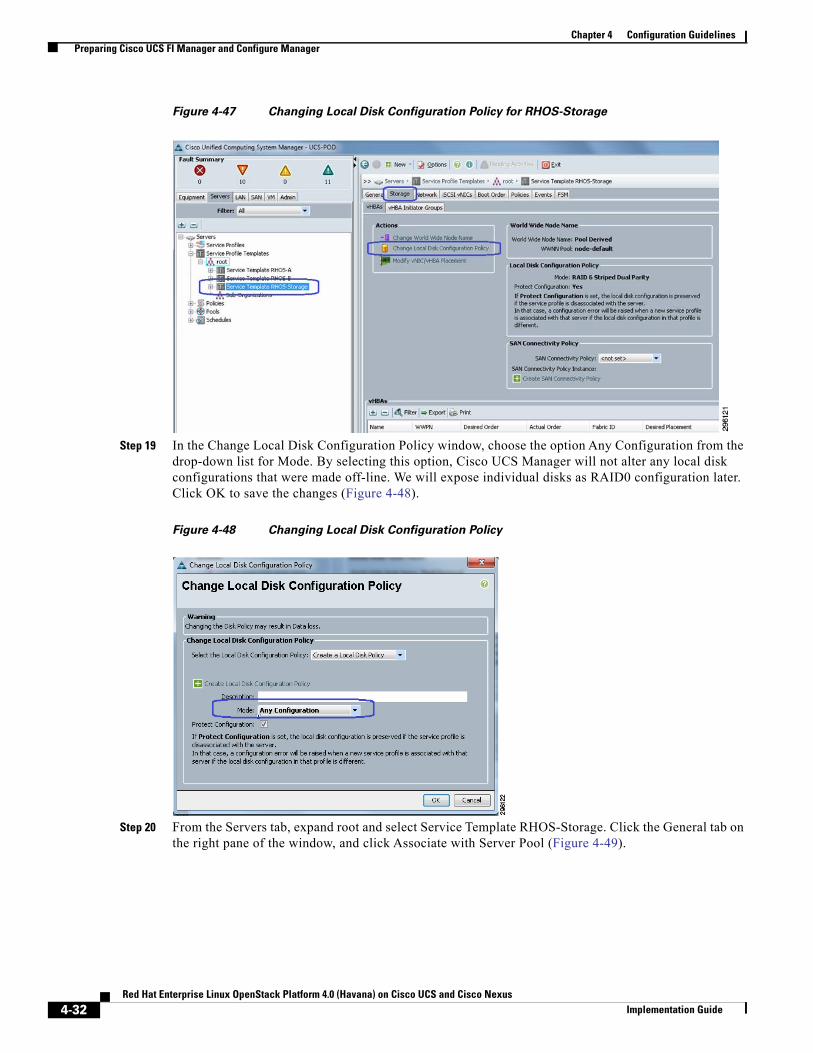
Chapter 4 Configuration GuidelinesPreparing Cisco UCS FI Manager and Configure Manager
Figure 4-47 Changing Local Disk Configuration Policy for RHOS-Storage
Step 19 In the Change Local Disk Configuration Policy window, choose the option Any Configuration from the drop-down list for Mode. By selecting this option, Cisco UCS Manager will not alter any local disk configurations that were made off-line. We will expose individual disks as RAID0 configuration later. Click OK to save the changes (Figure 4-48).
Figure 4-48 Changing Local Disk Configuration Policy
Step 20 From the Servers tab, expand root and select Service Template RHOS-Storage. Click the General tab on the right pane of the window, and click Associate with Server Pool (Figure 4-49).
4-32Red Hat Enterprise Linux OpenStack Platform 4.0 (Havana) on Cisco UCS and Cisco Nexus
Implementation Guide
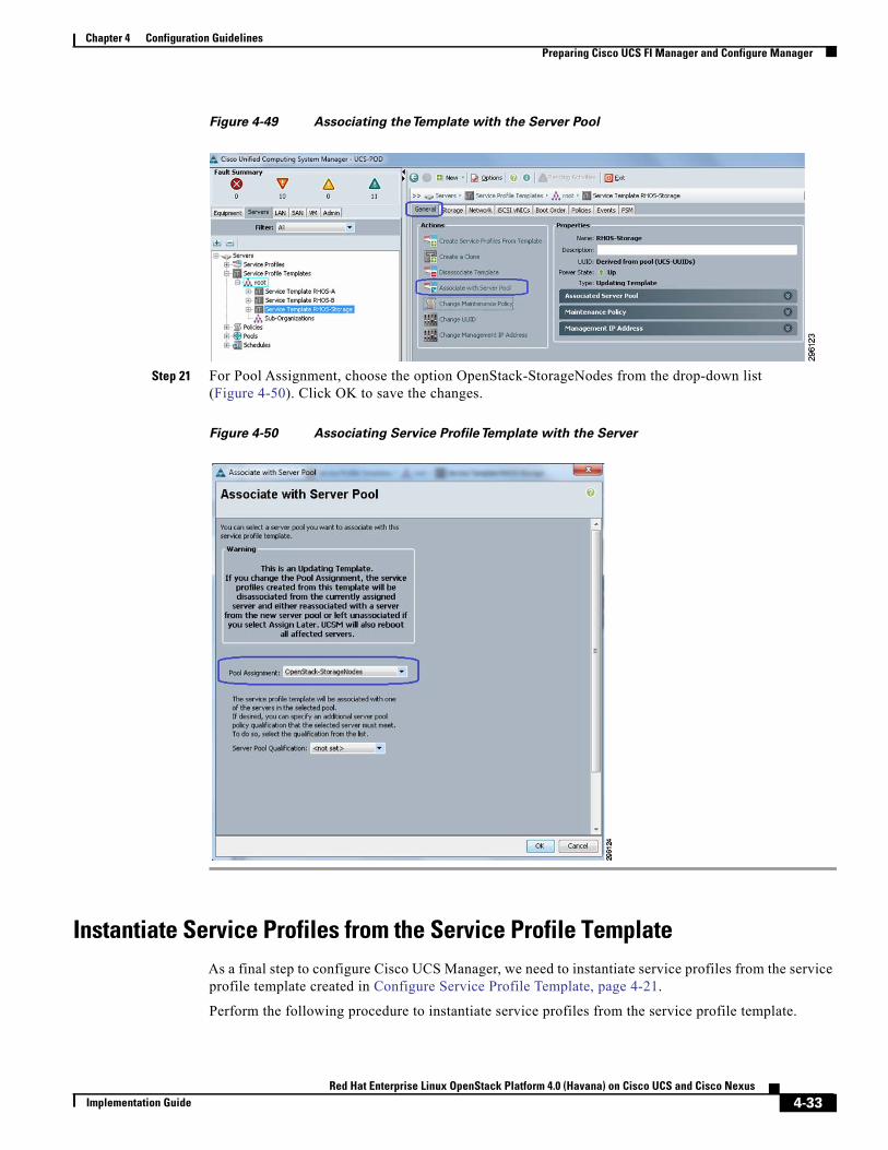
Chapter 4 Configuration GuidelinesPreparing Cisco UCS FI Manager and Configure Manager
Figure 4-49 Associating theTemplate with the Server Pool
Step 21 For Pool Assignment, choose the option OpenStack-StorageNodes from the drop-down list (Figure 4-50). Click OK to save the changes.
Figure 4-50 Associating Service ProfileTemplate with the Server
Instantiate Service Profiles from the Service Profile TemplateAs a final step to configure Cisco UCS Manager, we need to instantiate service profiles from the service profile template created in Configure Service Profile Template, page 4-21.
Perform the following procedure to instantiate service profiles from the service profile template.
4-33Red Hat Enterprise Linux OpenStack Platform 4.0 (Havana) on Cisco UCS and Cisco Nexus
Implementation Guide
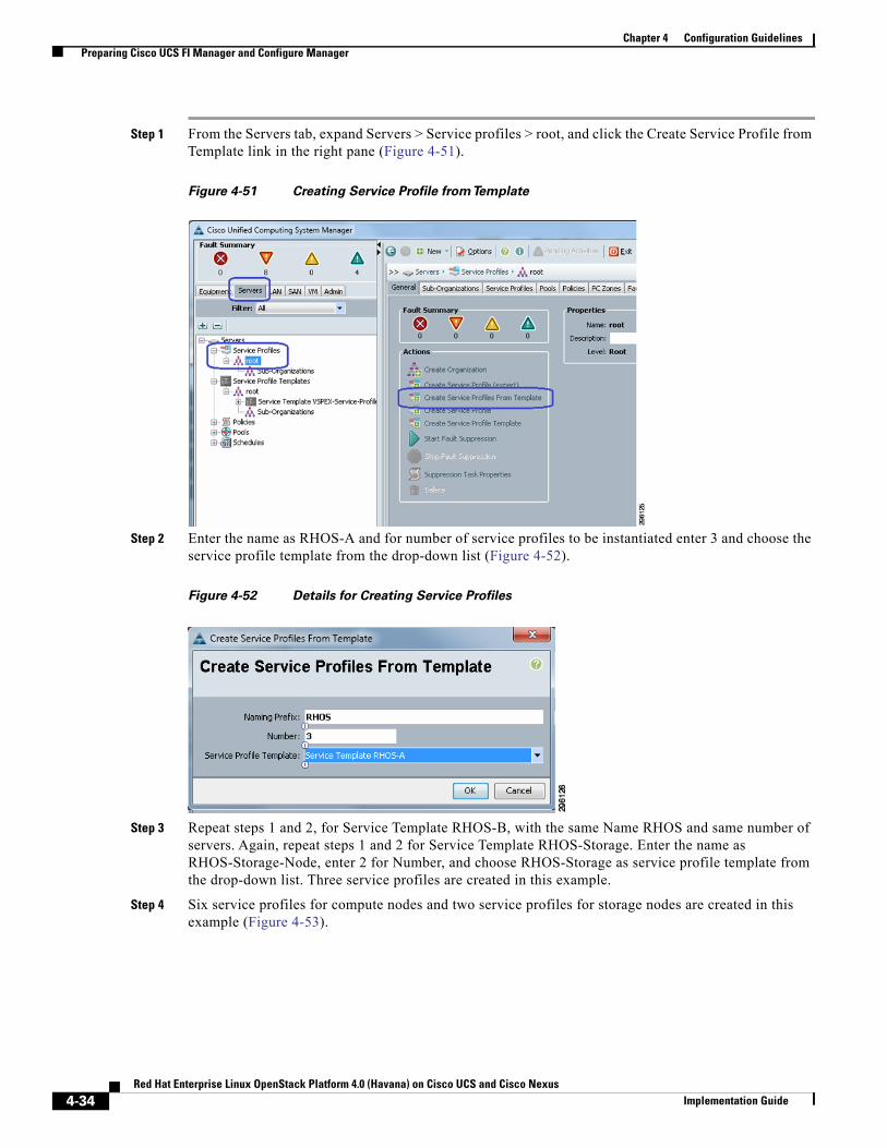
Chapter 4 Configuration GuidelinesPreparing Cisco UCS FI Manager and Configure Manager
Step 1 From the Servers tab, expand Servers > Service profiles > root, and click the Create Service Profile from Template link in the right pane (Figure 4-51).
Figure 4-51 Creating Service Profile fromTemplate
Step 2 Enter the name as RHOS-A and for number of service profiles to be instantiated enter 3 and choose the service profile template from the drop-down list (Figure 4-52).
Figure 4-52 Details for Creating Service Profiles
Step 3 Repeat steps 1 and 2, for Service Template RHOS-B, with the same Name RHOS and same number of servers. Again, repeat steps 1 and 2 for Service Template RHOS-Storage. Enter the name as RHOS-Storage-Node, enter 2 for Number, and choose RHOS-Storage as service profile template from the drop-down list. Three service profiles are created in this example.
Step 4 Six service profiles for compute nodes and two service profiles for storage nodes are created in this example (Figure 4-53).
4-34Red Hat Enterprise Linux OpenStack Platform 4.0 (Havana) on Cisco UCS and Cisco Nexus
Implementation Guide
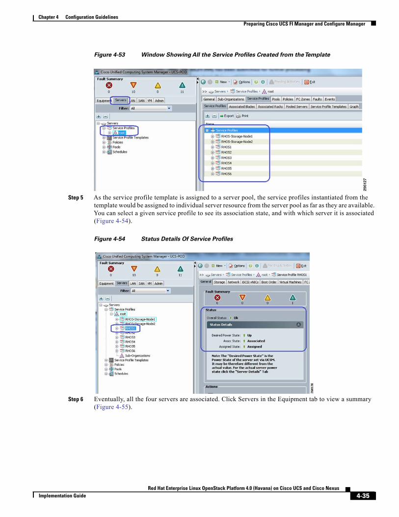
Chapter 4 Configuration GuidelinesPreparing Cisco UCS FI Manager and Configure Manager
Figure 4-53 Window Showing All the Service Profiles Created from theTemplate
Step 5 As the service profile template is assigned to a server pool, the service profiles instantiated from the template would be assigned to individual server resource from the server pool as far as they are available. You can select a given service profile to see its association state, and with which server it is associated (Figure 4-54).
Figure 4-54 Status Details Of Service Profiles
Step 6 Eventually, all the four servers are associated. Click Servers in the Equipment tab to view a summary (Figure 4-55).
4-35Red Hat Enterprise Linux OpenStack Platform 4.0 (Havana) on Cisco UCS and Cisco Nexus
Implementation Guide
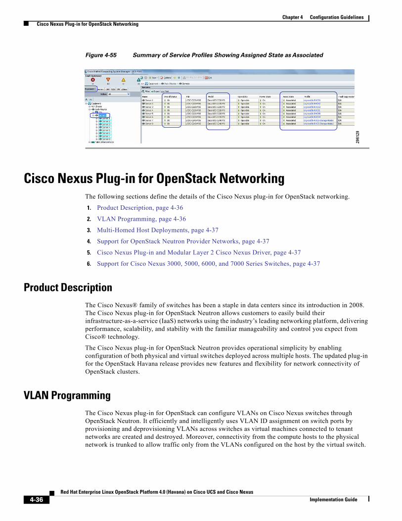
Chapter 4 Configuration GuidelinesCisco Nexus Plug-in for OpenStack Networking
Figure 4-55 Summary of Service Profiles Showing Assigned State as Associated
Cisco Nexus Plug-in for OpenStack NetworkingThe following sections define the details of the Cisco Nexus plug-in for OpenStack networking.
1. Product Description, page 4-36
2. VLAN Programming, page 4-36
3. Multi-Homed Host Deployments, page 4-37
4. Support for OpenStack Neutron Provider Networks, page 4-37
5. Cisco Nexus Plug-in and Modular Layer 2 Cisco Nexus Driver, page 4-37
6. Support for Cisco Nexus 3000, 5000, 6000, and 7000 Series Switches, page 4-37
Product DescriptionThe Cisco Nexus® family of switches has been a staple in data centers since its introduction in 2008. The Cisco Nexus plug-in for OpenStack Neutron allows customers to easily build their infrastructure-as-a-service (IaaS) networks using the industry’s leading networking platform, delivering performance, scalability, and stability with the familiar manageability and control you expect from Cisco® technology.
The Cisco Nexus plug-in for OpenStack Neutron provides operational simplicity by enabling configuration of both physical and virtual switches deployed across multiple hosts. The updated plug-in for the OpenStack Havana release provides new features and flexibility for network connectivity of OpenStack clusters.
VLAN ProgrammingThe Cisco Nexus plug-in for OpenStack can configure VLANs on Cisco Nexus switches through OpenStack Neutron. It efficiently and intelligently uses VLAN ID assignment on switch ports by provisioning and deprovisioning VLANs across switches as virtual machines connected to tenant networks are created and destroyed. Moreover, connectivity from the compute hosts to the physical network is trunked to allow traffic only from the VLANs configured on the host by the virtual switch.
4-36Red Hat Enterprise Linux OpenStack Platform 4.0 (Havana) on Cisco UCS and Cisco Nexus
Implementation Guide
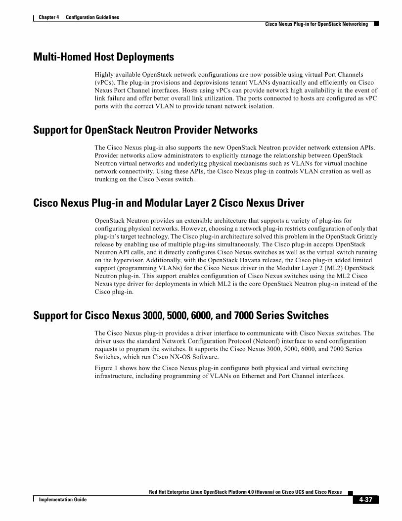
Chapter 4 Configuration GuidelinesCisco Nexus Plug-in for OpenStack Networking
Multi-Homed Host DeploymentsHighly available OpenStack network configurations are now possible using virtual Port Channels (vPCs). The plug-in provisions and deprovisions tenant VLANs dynamically and efficiently on Cisco Nexus Port Channel interfaces. Hosts using vPCs can provide network high availability in the event of link failure and offer better overall link utilization. The ports connected to hosts are configured as vPC ports with the correct VLAN to provide tenant network isolation.
Support for OpenStack Neutron Provider NetworksThe Cisco Nexus plug-in also supports the new OpenStack Neutron provider network extension APIs. Provider networks allow administrators to explicitly manage the relationship between OpenStack Neutron virtual networks and underlying physical mechanisms such as VLANs for virtual machine network connectivity. Using these APIs, the Cisco Nexus plug-in controls VLAN creation as well as trunking on the Cisco Nexus switch.
Cisco Nexus Plug-in and Modular Layer 2 Cisco Nexus DriverOpenStack Neutron provides an extensible architecture that supports a variety of plug-ins for configuring physical networks. However, choosing a network plug-in restricts configuration of only that plug-in’s target technology. The Cisco plug-in architecture solved this problem in the OpenStack Grizzly release by enabling use of multiple plug-ins simultaneously. The Cisco plug-in accepts OpenStack Neutron API calls, and it directly configures Cisco Nexus switches as well as the virtual switch running on the hypervisor. Additionally, with the OpenStack Havana release, the Cisco plug-in added limited support (programming VLANs) for the Cisco Nexus driver in the Modular Layer 2 (ML2) OpenStack Neutron plug-in. This support enables configuration of Cisco Nexus switches using the ML2 Cisco Nexus type driver for deployments in which ML2 is the core OpenStack Neutron plug-in instead of the Cisco plug-in.
Support for Cisco Nexus 3000, 5000, 6000, and 7000 Series SwitchesThe Cisco Nexus plug-in provides a driver interface to communicate with Cisco Nexus switches. The driver uses the standard Network Configuration Protocol (Netconf) interface to send configuration requests to program the switches. It supports the Cisco Nexus 3000, 5000, 6000, and 7000 Series Switches, which run Cisco NX-OS Software.
Figure 1 shows how the Cisco Nexus plug-in configures both physical and virtual switching infrastructure, including programming of VLANs on Ethernet and Port Channel interfaces.
4-37Red Hat Enterprise Linux OpenStack Platform 4.0 (Havana) on Cisco UCS and Cisco Nexus
Implementation Guide
Chapter 4 Configuration GuidelinesCreating OpenStack Setup on Nexus Plug-in Based Topology
Creating OpenStack Setup on Nexus Plug-in Based TopologyThe following sections define the details of creating an OpenStack setup on the Nexus plug-in topology.
1. Foreman Installation, page 4-38
2. Prerequisites and Getting the Red Hat Enterprise Linux 6.5 ISO, page 4-38
3. Installation of the Build Node, page 4-41
4. Subscribing to Red hat, page 4-41
5. Configuring the Firewall, page 4-44
6. Installing Foreman Packages, page 4-44
Foreman InstallationForeman based installation for Red-Hat OpenStack Platform 4.0 requires the creation of a build-server. It acts as the puppet master, and provides PXE for servers that would be future nodes in the OpenStack setup.
Prerequisites and Getting the Red Hat Enterprise Linux 6.5 ISOAs a prerequisite you would require a red hat account and a Red Hat Enterprise Linux 6.5 ISO. If you do not already have Red Hat Enterprise Linux 6.5 ISO you can download it on a separate machine using the steps mentioned in this section below.
Step 1 Once you have an account with red hat, download the Red Hat Enterprise Linux 6.5 ISO Image (Figure 4-56).
4-38Red Hat Enterprise Linux OpenStack Platform 4.0 (Havana) on Cisco UCS and Cisco Nexus
Implementation Guide
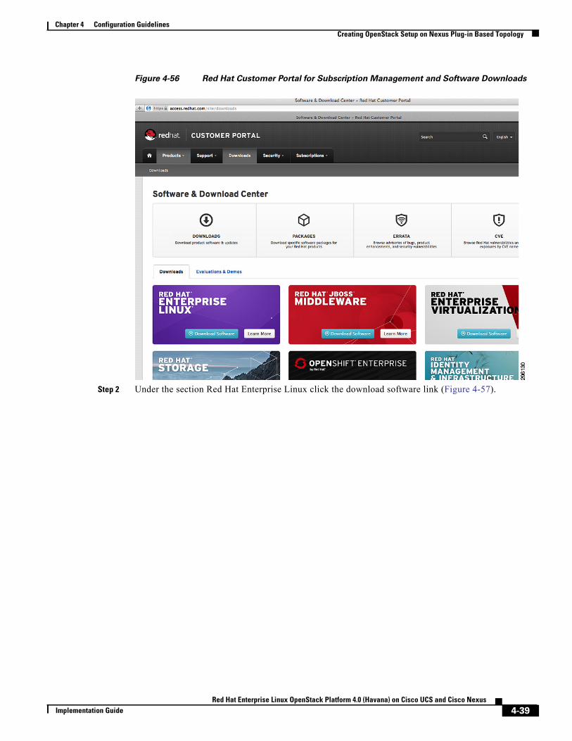
Chapter 4 Configuration GuidelinesCreating OpenStack Setup on Nexus Plug-in Based Topology
Figure 4-56 Red Hat Customer Portal for Subscription Management and Software Downloads
Step 2 Under the section Red Hat Enterprise Linux click the download software link (Figure 4-57).
4-39Red Hat Enterprise Linux OpenStack Platform 4.0 (Havana) on Cisco UCS and Cisco Nexus
Implementation Guide
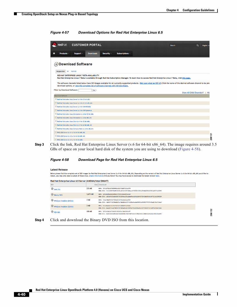
Chapter 4 Configuration GuidelinesCreating OpenStack Setup on Nexus Plug-in Based Topology
Figure 4-57 Download Options for Red Hat Enterprise Linux 6.5
Step 3 Click the link, Red Hat Enterprise Linux Server (v.6 for 64-bit x86_64). The image requires around 3.5 GBs of space on your local hard disk of the system you are using to download (Figure 4-58).
Figure 4-58 Download Page for Red Hat Enterprise Linux 6.5
Step 4 Click and download the Binary DVD ISO from this location.
4-40Red Hat Enterprise Linux OpenStack Platform 4.0 (Havana) on Cisco UCS and Cisco Nexus
Implementation Guide
Chapter 4 Configuration GuidelinesCreating OpenStack Setup on Nexus Plug-in Based Topology
Installation of the Build NodeThe downloaded ISO should be attached as a virtual media in Cisco UCS-CIMC/UCSM. Upon booting from the ISO, complete the install of Red Hat Enterprise Linux 6.5 on the server designated at the build-node. The installation can be completed using GUI based installer, which would be prompted open booting from the red hat Red Hat Enterprise Linux 6.5 ISO.
Once the base Red Hat Enterprise Linux 6.5 server is properly installed. Reboot the machine. You need to make below mentioned changes as a prerequisite before installing Foreman.
Configure the management network between the build node and the future OpenStack nodes. Configure one of the available Ethernet interface with an IP from the management network.
Puppet certificate signing uses the Fully Qualified Domain Name (FQDN); Hence, make sure that the system has a Fully Qualified Domain Name configured properly. Which means that appropriate entries under /etc/hosts and /etc/sysconfig/network should be done. To validate if the host name is properly set, confirm if the output of hostname –f yields a FQDN.
Subscribing to Red hatRegistration of the Red Hat Enterprise Linux 6.5 Server with red hat needs to be done to make packages and channels available to the Server. This can be done via Subscription manager or Classic RHN. Subscription Manager is the preferred method. Alternately, RHN Classic could also be used. Both the methods are described below. Only one method mentioned below should be applied for a given Red Hat Enterprise Linux server.
Using Subscription Manager
Perform the following procedure to use Subscription Manager for Red Hat Enterprise Linux 6.5 Server registration.
Step 1 If the setup is behind the proxy, edit the file /etc/rhsm/rhsm.conf and change the parameter proxy_hostname, proxy_port, proxy_user, and proxy_password with proxy details in your network.
Step 2 Register to the subscription manager using the subscription-manager register command.
Step 3 Use the subscription-manager list command to locate the pool identifier of the Red Hat Enterprise Linux subscription.
# subscription-manager list --available
Step 4 Use the subscription-manager attach command to attach the subscription identified in the previous step. The POOLID needs to be identified from the previous step that contains “Red Hat Openstack Platform” which should be used for this setup.
# subscription-manager attach --pool=POOLID
Step 5 Run the yum repolist command. This command ensures that the repository configuration file /etc/yum.repos.d/redhat.repo exists and is up to date.
# yum repolist
Step 6 Once repository metadata has been downloaded and examined, the list of repositories enabled will be displayed, along with the number of available packages
id repo name status
4-41Red Hat Enterprise Linux OpenStack Platform 4.0 (Havana) on Cisco UCS and Cisco Nexus
Implementation Guide
Chapter 4 Configuration GuidelinesCreating OpenStack Setup on Nexus Plug-in Based Topology
rhel-6-server-rpms Red Hat Enterprise Linux 6 Server (RPMs) 8,816
repolist: 8,816
�The output displayed may differ from that which appears when you run the yum repolist command on your system. In particular, the number of packages listed varies if or when additional packages are added to the rhel-6-server-rpms repository.
Step 7 Use either the subscription-manager or yum-config-manager commands to enable or disable the appropriate software repositories (channels). Unless already installed, you can use the following to install yum-config-manager:
# yum install -y yum-utils
For example, to ensure that the repository for Red Hat Enterprise Linux OpenStack Platform 3 (Grizzly) has been disabled, run:
# yum-config-manager --disable rhel-server-ost-6-3-rpmsLoaded plugins: product-id==== repo: rhel-server-ost-6-3-rpms ====[rhel-server-ost-6-3-rpms]bandwidth = 0base_persistdir = /var/lib/yum/repos/x86_64/6Serverbaseurl =https://cdn.redhat.com/content/dist/rhel/server/6/6Server/x86_64/openstack/3/oscache = 0cachedir = /var/cache/yum/x86_64/6Server/rhel-server-ost-6-3-rpmscost = 1000enabled = False
Yum treats the values True and 1 as equivalent. As a result the output on your system may instead contain this string: enabled = 1
Step 8 Run the yum repolist command to ensure the repository configuration file /etc/yum.repos.d/redhat.repo exists and is up to date.
# yum repolist
Once repository metadata has been downloaded and examined, the current list of enabled repositories is displayed, along with the number of available packages.
For example:repo id repo name status
rhel-6-server-rpms Red Hat Enterprise Linux 6 Server (RPMs) 11,610+460rhel-6-server-openstack-4.0-rpms \Red Hat Enterprise Linux OpenStack Platform 4 (RPMs) 487+143
Step 9 Use the yum-config-manager command to enable the Red Hat Enterprise Linux OpenStack Platform repository. Remember to use the repository name listed in the Red Hat Enterprise Linux OpenStack Platform Release Notes.
# yum-config-manager --enable REPO_NAME
Step 10 Install the yum-plugin-priorities package. The yum-plugin-priorities package provides a yum plug-in allowing configuration of per-repository priorities.
# yum install -y yum-plugin-priorities
Step 11 Use the yum-config-manager command to set the priority of the Red Hat Enterprise Linux OpenStack Platform software repository to 1. This is the highest priority value supported by the yum-plugin-priorities plug-in. Remember to use the repository name listed in the Red Hat Enterprise Linux OpenStack Platform Release Notes.
4-42Red Hat Enterprise Linux OpenStack Platform 4.0 (Havana) on Cisco UCS and Cisco Nexus
Implementation Guide
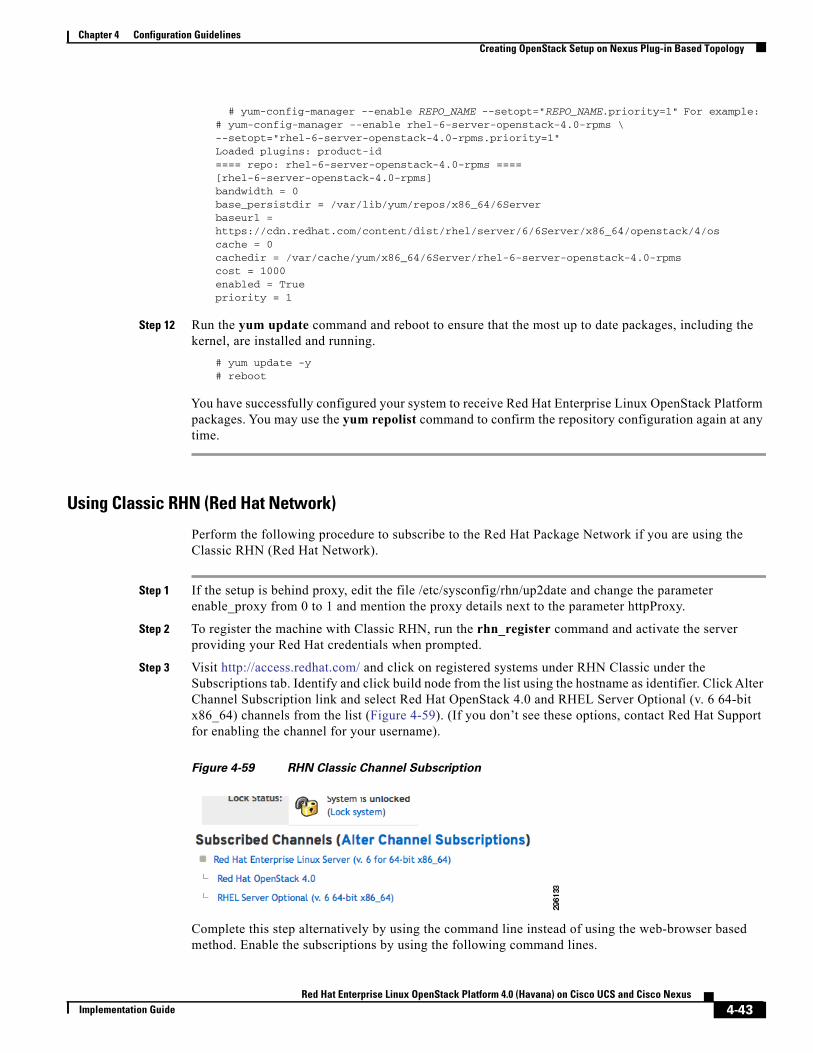
Chapter 4 Configuration GuidelinesCreating OpenStack Setup on Nexus Plug-in Based Topology
# yum-config-manager --enable REPO_NAME --setopt="REPO_NAME.priority=1" For example:# yum-config-manager --enable rhel-6-server-openstack-4.0-rpms \--setopt="rhel-6-server-openstack-4.0-rpms.priority=1"Loaded plugins: product-id==== repo: rhel-6-server-openstack-4.0-rpms ====[rhel-6-server-openstack-4.0-rpms]bandwidth = 0base_persistdir = /var/lib/yum/repos/x86_64/6Serverbaseurl =https://cdn.redhat.com/content/dist/rhel/server/6/6Server/x86_64/openstack/4/oscache = 0cachedir = /var/cache/yum/x86_64/6Server/rhel-6-server-openstack-4.0-rpmscost = 1000enabled = Truepriority = 1
Step 12 Run the yum update command and reboot to ensure that the most up to date packages, including the kernel, are installed and running.
# yum update -y# reboot
You have successfully configured your system to receive Red Hat Enterprise Linux OpenStack Platform packages. You may use the yum repolist command to confirm the repository configuration again at any time.
Using Classic RHN (Red Hat Network)
Perform the following procedure to subscribe to the Red Hat Package Network if you are using the Classic RHN (Red Hat Network).
Step 1 If the setup is behind proxy, edit the file /etc/sysconfig/rhn/up2date and change the parameter enable_proxy from 0 to 1 and mention the proxy details next to the parameter httpProxy.
Step 2 To register the machine with Classic RHN, run the rhn_register command and activate the server providing your Red Hat credentials when prompted.
Step 3 Visit http://access.redhat.com/ and click on registered systems under RHN Classic under the Subscriptions tab. Identify and click build node from the list using the hostname as identifier. Click Alter Channel Subscription link and select Red Hat OpenStack 4.0 and RHEL Server Optional (v. 6 64-bit x86_64) channels from the list (Figure 4-59). (If you don’t see these options, contact Red Hat Support for enabling the channel for your username).
Figure 4-59 RHN Classic Channel Subscription
Complete this step alternatively by using the command line instead of using the web-browser based method. Enable the subscriptions by using the following command lines.
4-43Red Hat Enterprise Linux OpenStack Platform 4.0 (Havana) on Cisco UCS and Cisco Nexus
Implementation Guide
Chapter 4 Configuration GuidelinesCreating OpenStack Setup on Nexus Plug-in Based Topology
# rhn-channel --add -channel= rhel-x86_64-server-6-ost-4 --user=<rhn-username>--password=<rhn-password># rhn-channel --add -channel= rhel-x86_64-server-6 --user=<rhn-username>--password=<rhn-password>
Step 4 Install the yum-plugin-priorities package which provides a yum plug-in allowing the configuration of per-repository priorities.
Step 5 Run the yum install -y yum-plugin-priorities command.
Step 6 Run the yum update command and reboot to ensure the most up to date packages, including the kernel, are installed and running.
# yum update -y
Step 7 Reboot the machine to complete the updates.# reboot
Configuring the FirewallThe lokkit binary is provided by the system-config-firewall-base package in Red Hat Enterprise Linux 6.5. Run the following lokkit commands as the root user to configure the firewall in preparation for the Foreman OpenStack Manager installation:
# lokkit --service http# lokkit --service https# lokkit --service dns# lokkit --service tftp# lokkit --port 8140:tcp
Installing Foreman PackagesPerform the following procedure to install Foreman packages.
Step 1 Log in to the system that will host the Foreman installation as the root user.
Step 2 Run the yum install -y openstack-foreman-installer foreman-selinux command to install the openstack-foreman-installer and foreman-selinux packages.
After the installation is complete, the Foreman installer is now locally installed and ready to be configured and run.
Note Refer to Workaround for Known Issues, page 4-45.
Step 3 Edit the Foreman Gateway with the IP of the gateway of the public network in the file /usr/share/openstack-foreman-installer/bin/foreman_server.sh.
Step 4 Alternatively, by command line, you can edit the parameter FOREMAN_PROVISIONING=true in file foreman.sh at /usr/share/open stack-foreman-installer/bin.
The default is now true and the same can be set/ overridden by setting the environment variable.
Step 5 Go to the directory /usr/share/openstack-foreman-installer/bin.# cd /usr/share/openstack-foreman-installer/bin
4-44Red Hat Enterprise Linux OpenStack Platform 4.0 (Havana) on Cisco UCS and Cisco Nexus
Implementation Guide
Chapter 4 Configuration GuidelinesCreating OpenStack Setup on Nexus Plug-in Based Topology
Step 6 Run the foreman_server.sh script and wait until it completely installs the Foreman build server on this server.
export FOREMAN_GATEWAY=<Gateway in your topology>export PROVISIONING_INTERFACE=<Provisioning Interface># sh foreman_server.sh
Step 7 After a successful run of this script your foreman server would be complete. To verify, open the web-based interface of foreman in a web-browser (Mozilla FireFox) by using IP address/hostname as the URL.
Workaround for Known Issues
Defect 1—Red Hat Bugillza 1078284
The stackforge version of puppet-neutron creates a symlink which is incompatible with Red Hat’s current deployment. There is a pending upstream fix. We'll need to make sure Red Hat packages incorporate this fix when its committed.
For now as a workaround, just comment out lines 174-178 from /usr/share/packstack/modules/neutron/manifests/plugins/cisco.pp#file {'/etc/neutron/plugin.ini':
# ensure => link,# target => '/etc/neutron/plugins/cisco/cisco_plugins.ini',# require => Package['neutron-plugin-cisco']#}
Fixed In Version: openstack-puppet-modules-2013.2-9.el6ost
Defect 2—Neutron Security Groups (Astapor #146)
When neutron security groups are enabled, VM booting fails. Any command accessing security groups returns a 404 error. Foreman was not configuring the Hybrid Firewall driver.
Red Hat Bugzilla 1078279
Defect 3—cisco_plugin.ini uses old nexus format (Astapor #146)
The nexus plug-in requires a new format for its configuration. This pull request updates the config file to match current config file formatting. Once this commit is merged, we'll need to make sure its included in Red Hat packaging.
Red Hat Bugzilla 1078279
Workaround: Create the file manually
4-45Red Hat Enterprise Linux OpenStack Platform 4.0 (Havana) on Cisco UCS and Cisco Nexus
Implementation Guide
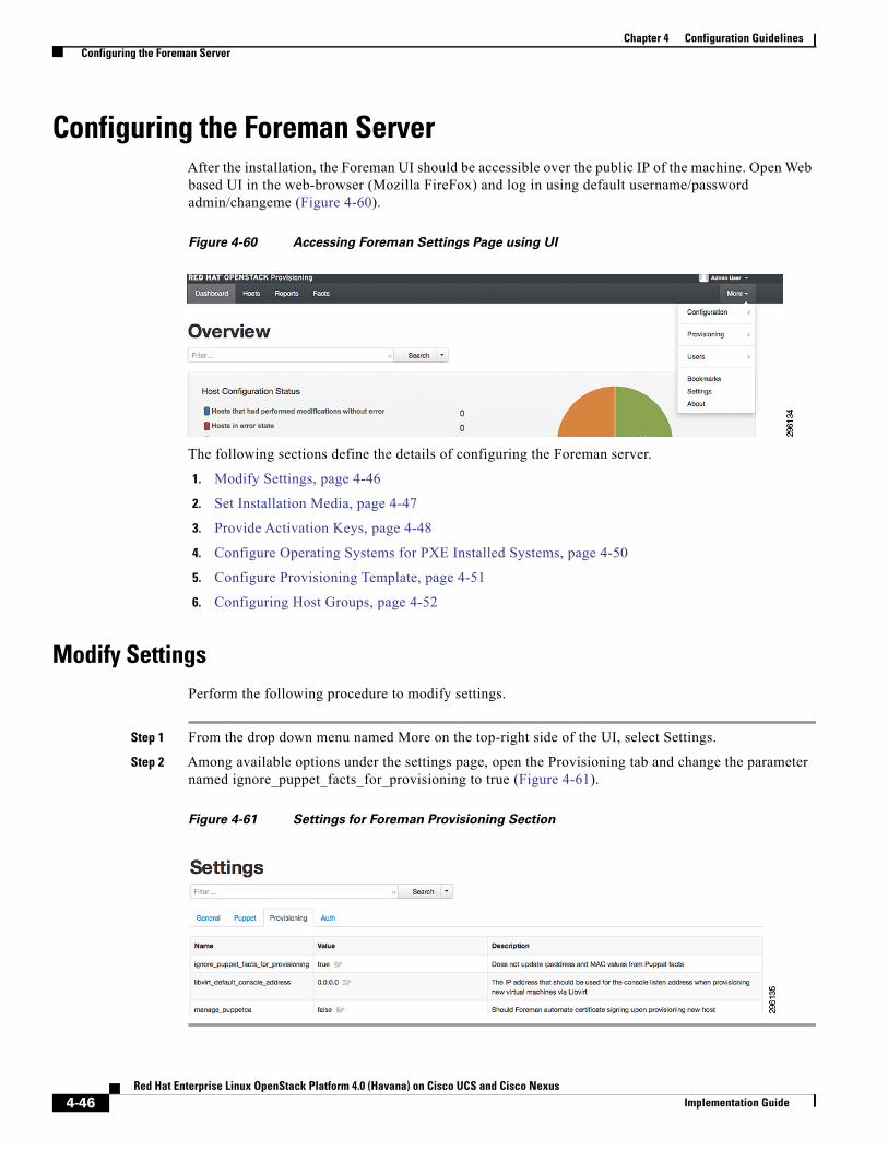
Chapter 4 Configuration GuidelinesConfiguring the Foreman Server
Configuring the Foreman ServerAfter the installation, the Foreman UI should be accessible over the public IP of the machine. Open Web based UI in the web-browser (Mozilla FireFox) and log in using default username/password admin/changeme (Figure 4-60).
Figure 4-60 Accessing Foreman Settings Page using UI
The following sections define the details of configuring the Foreman server.
1. Modify Settings, page 4-46
2. Set Installation Media, page 4-47
3. Provide Activation Keys, page 4-48
4. Configure Operating Systems for PXE Installed Systems, page 4-50
5. Configure Provisioning Template, page 4-51
6. Configuring Host Groups, page 4-52
Modify SettingsPerform the following procedure to modify settings.
Step 1 From the drop down menu named More on the top-right side of the UI, select Settings.
Step 2 Among available options under the settings page, open the Provisioning tab and change the parameter named ignore_puppet_facts_for_provisioning to true (Figure 4-61).
Figure 4-61 Settings for Foreman Provisioning Section
4-46Red Hat Enterprise Linux OpenStack Platform 4.0 (Havana) on Cisco UCS and Cisco Nexus
Implementation Guide
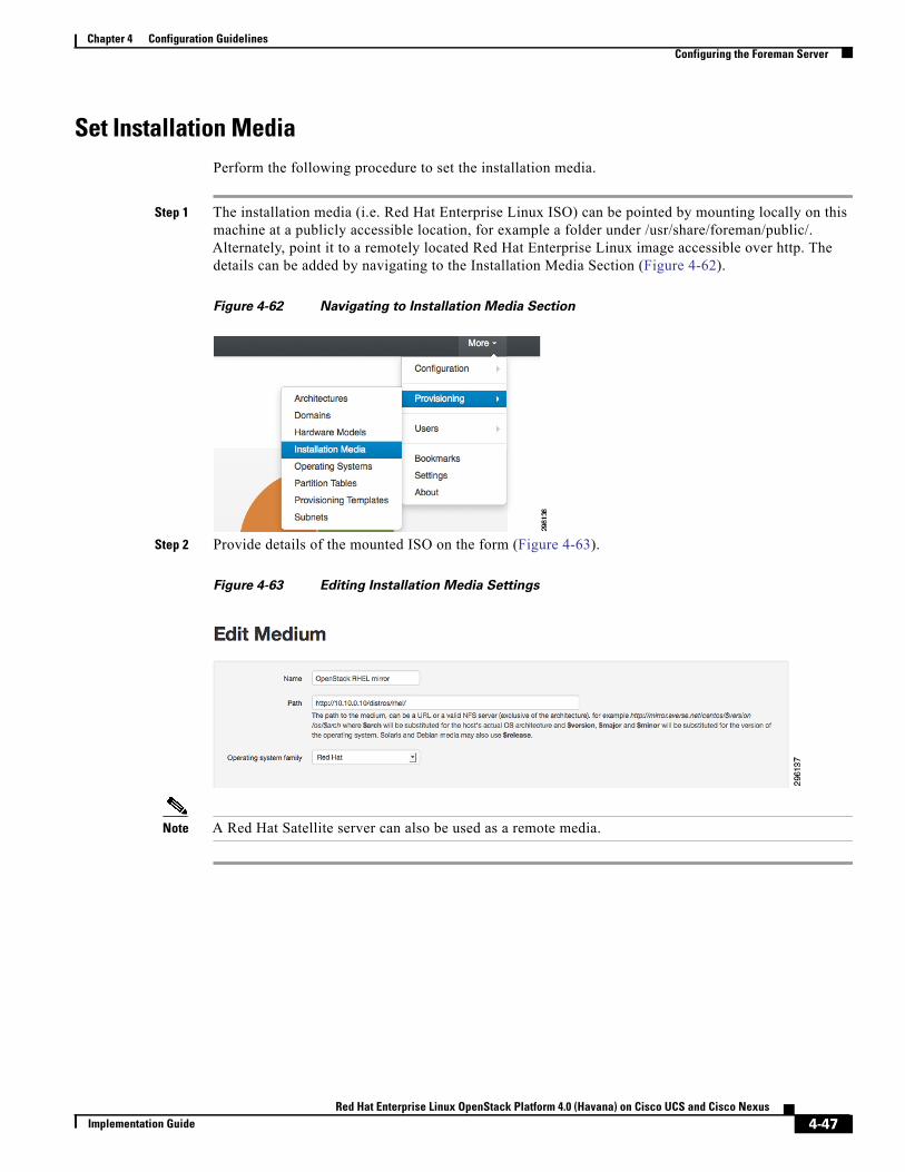
Chapter 4 Configuration GuidelinesConfiguring the Foreman Server
Set Installation MediaPerform the following procedure to set the installation media.
Step 1 The installation media (i.e. Red Hat Enterprise Linux ISO) can be pointed by mounting locally on this machine at a publicly accessible location, for example a folder under /usr/share/foreman/public/. Alternately, point it to a remotely located Red Hat Enterprise Linux image accessible over http. The details can be added by navigating to the Installation Media Section (Figure 4-62).
Figure 4-62 Navigating to Installation Media Section
Step 2 Provide details of the mounted ISO on the form (Figure 4-63).
Figure 4-63 Editing Installation Media Settings
Note A Red Hat Satellite server can also be used as a remote media.
4-47Red Hat Enterprise Linux OpenStack Platform 4.0 (Havana) on Cisco UCS and Cisco Nexus
Implementation Guide
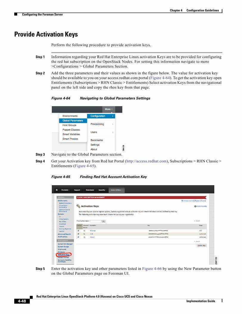
Chapter 4 Configuration GuidelinesConfiguring the Foreman Server
Provide Activation KeysPerform the following procedure to provide activation keys.
Step 1 Information regarding your Red Hat Enterprise Linux activation Keys are to be provided for configuring the red hat subscription on the OpenStack Nodes. For setting this information navigate to more >Configurations > Global Parameters Section.
Step 2 Add the three parameters and their values as shown in the figure below. The value for activation key should be available to you on your access.redhat.com portal (Figure 4-64). To get the activation key open Entitlements (Subscriptions > RHN Classic > Entitlements) Select activation Keys from the navigational panel on the left side and copy the rhos key from that page.
Figure 4-64 Navigating to Global Parameters Settings
Step 3 Navigate to the Global Parameters section.
Step 4 Get your Activation key from Red hat Portal (http://access.redhat.com), Subscriptions > RHN Classic > Entitlements (Figure 4-65).
Figure 4-65 Finding Red Hat Account Activation Key
Step 5 Enter the activation key and other parameters listed in Figure 4-66 by using the New Parameter button on the Global Parameters page on Foreman UI.
4-48Red Hat Enterprise Linux OpenStack Platform 4.0 (Havana) on Cisco UCS and Cisco Nexus
Implementation Guide
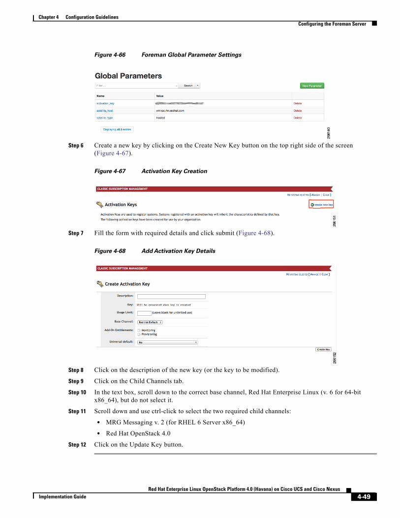
Chapter 4 Configuration GuidelinesConfiguring the Foreman Server
Figure 4-66 Foreman Global Parameter Settings
Step 6 Create a new key by clicking on the Create New Key button on the top right side of the screen (Figure 4-67).
Figure 4-67 Activation Key Creation
Step 7 Fill the form with required details and click submit (Figure 4-68).
Figure 4-68 Add Activation Key Details
Step 8 Click on the description of the new key (or the key to be modified).
Step 9 Click on the Child Channels tab.
Step 10 In the text box, scroll down to the correct base channel, Red Hat Enterprise Linux (v. 6 for 64-bit x86_64), but do not select it.
Step 11 Scroll down and use ctrl-click to select the two required child channels:
• MRG Messaging v. 2 (for RHEL 6 Server x86_64)
• Red Hat OpenStack 4.0
Step 12 Click on the Update Key button.
4-49Red Hat Enterprise Linux OpenStack Platform 4.0 (Havana) on Cisco UCS and Cisco Nexus
Implementation Guide
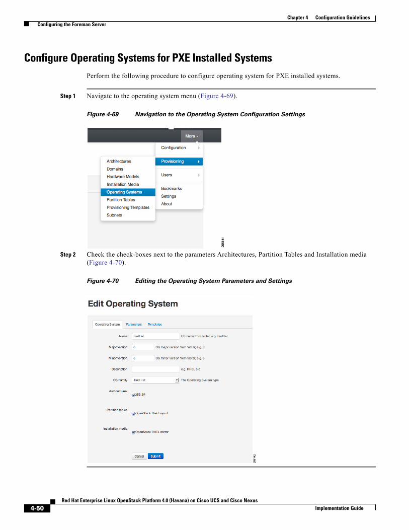
Chapter 4 Configuration GuidelinesConfiguring the Foreman Server
Configure Operating Systems for PXE Installed SystemsPerform the following procedure to configure operating system for PXE installed systems.
Step 1 Navigate to the operating system menu (Figure 4-69).
Figure 4-69 Navigation to the Operating System Configuration Settings
Step 2 Check the check-boxes next to the parameters Architectures, Partition Tables and Installation media (Figure 4-70).
Figure 4-70 Editing the Operating System Parameters and Settings
4-50Red Hat Enterprise Linux OpenStack Platform 4.0 (Havana) on Cisco UCS and Cisco Nexus
Implementation Guide
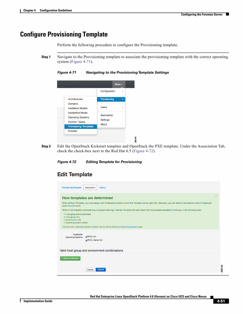
Chapter 4 Configuration GuidelinesConfiguring the Foreman Server
Configure Provisioning TemplatePerform the following procedure to configure the Provisioning template.
Step 1 Navigate to the Provisioning template to associate the provisioning template with the correct operating system (Figure 4-71).
Figure 4-71 Navigating to the ProvisioningTemplate Settings
Step 2 Edit the OpenStack Kickstart template and OpenStack the PXE template. Under the Association Tab, check the check-box next to the Red Hat 6.5 (Figure 4-72).
Figure 4-72 EditingTemplate for Provisioning
4-51Red Hat Enterprise Linux OpenStack Platform 4.0 (Havana) on Cisco UCS and Cisco Nexus
Implementation Guide
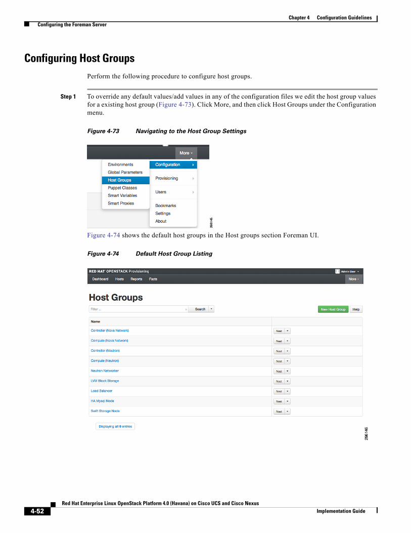
Chapter 4 Configuration GuidelinesConfiguring the Foreman Server
Configuring Host GroupsPerform the following procedure to configure host groups.
Step 1 To override any default values/add values in any of the configuration files we edit the host group values for a existing host group (Figure 4-73). Click More, and then click Host Groups under the Configuration menu.
Figure 4-73 Navigating to the Host Group Settings
Figure 4-74 shows the default host groups in the Host groups section Foreman UI.
Figure 4-74 Default Host Group Listing
4-52Red Hat Enterprise Linux OpenStack Platform 4.0 (Havana) on Cisco UCS and Cisco Nexus
Implementation Guide
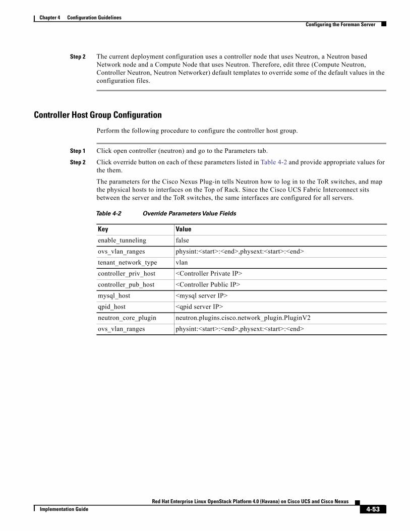
Chapter 4 Configuration GuidelinesConfiguring the Foreman Server
Step 2 The current deployment configuration uses a controller node that uses Neutron, a Neutron based Network node and a Compute Node that uses Neutron. Therefore, edit three (Compute Neutron, Controller Neutron, Neutron Networker) default templates to override some of the default values in the configuration files.
Controller Host Group Configuration
Perform the following procedure to configure the controller host group.
Step 1 Click open controller (neutron) and go to the Parameters tab.
Step 2 Click override button on each of these parameters listed in Table 4-2 and provide appropriate values for the them.
The parameters for the Cisco Nexus Plug-in tells Neutron how to log in to the ToR switches, and map the physical hosts to interfaces on the Top of Rack. Since the Cisco UCS Fabric Interconnect sits between the server and the ToR switches, the same interfaces are configured for all servers.
Table 4-2 Override Parameters Value Fields
Key Value
enable_tunneling false
ovs_vlan_ranges physint:<start>:<end>,physext:<start>:<end>
tenant_network_type vlan
controller_priv_host <Controller Private IP>
controller_pub_host <Controller Public IP>
mysql_host <mysql server IP>
qpid_host <qpid server IP>
neutron_core_plugin neutron.plugins.cisco.network_plugin.PluginV2
ovs_vlan_ranges physint:<start>:<end>,physext:<start>:<end>
4-53Red Hat Enterprise Linux OpenStack Platform 4.0 (Havana) on Cisco UCS and Cisco Nexus
Implementation Guide
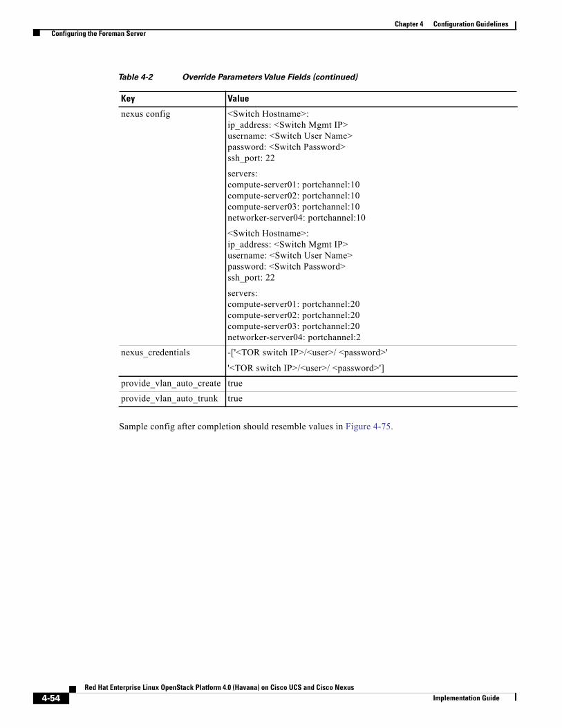
Chapter 4 Configuration GuidelinesConfiguring the Foreman Server
Sample config after completion should resemble values in Figure 4-75.
nexus config <Switch Hostname>:ip_address: <Switch Mgmt IP>username: <Switch User Name>password: <Switch Password>ssh_port: 22
servers:compute-server01: portchannel:10compute-server02: portchannel:10compute-server03: portchannel:10networker-server04: portchannel:10
<Switch Hostname>:ip_address: <Switch Mgmt IP>username: <Switch User Name>password: <Switch Password>ssh_port: 22
servers:compute-server01: portchannel:20compute-server02: portchannel:20compute-server03: portchannel:20networker-server04: portchannel:2
nexus_credentials -['<TOR switch IP>/<user>/ <password>'
'<TOR switch IP>/<user>/ <password>']
provide_vlan_auto_create true
provide_vlan_auto_trunk true
Table 4-2 Override Parameters Value Fields (continued)
Key Value
4-54Red Hat Enterprise Linux OpenStack Platform 4.0 (Havana) on Cisco UCS and Cisco Nexus
Implementation Guide
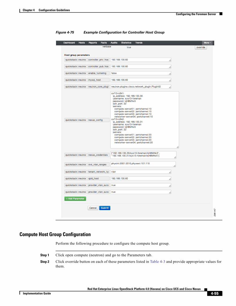
Chapter 4 Configuration GuidelinesConfiguring the Foreman Server
Figure 4-75 Example Configuration for Controller Host Group
Compute Host Group Configuration
Perform the following procedure to configure the compute host group.
Step 1 Click open compute (neutron) and go to the Parameters tab.
Step 2 Click override button on each of these parameters listed in Table 4-3 and provide appropriate values for them.
4-55Red Hat Enterprise Linux OpenStack Platform 4.0 (Havana) on Cisco UCS and Cisco Nexus
Implementation Guide
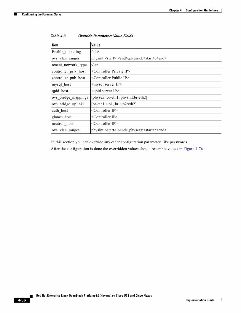
Chapter 4 Configuration GuidelinesConfiguring the Foreman Server
In this section you can override any other configuration parameter, like passwords.
After the configuration is done the overridden values should resemble values in Figure 4-76
Table 4-3 Override Parameters Value Fields
Key Value
Enable_tunneling false
ovs_vlan_ranges physint:<start>:<end>,physext:<start>:<end>
tenant_network_type vlan
controller_priv_host <Controller Private IP>
controller_pub_host <Controller Public IP>
mysql_host <mysql server IP>
qpid_host <qpid server IP>
ovs_bridge_mappings [physext:br-eth1, physint:br-eth2]
ovs_bridge_uplinks [br-eth1:eth1, br-eth2:eth2]
auth_host <Controller IP>
glance_host <Controller IP>
neutron_host <Controller IP>
ovs_vlan_ranges physint:<start>:<end>,physext:<start>:<end>
4-56Red Hat Enterprise Linux OpenStack Platform 4.0 (Havana) on Cisco UCS and Cisco Nexus
Implementation Guide
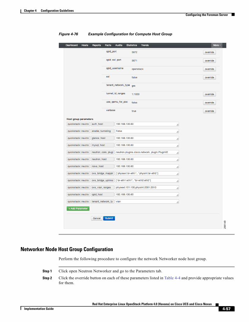
Chapter 4 Configuration GuidelinesConfiguring the Foreman Server
Figure 4-76 Example Configuration for Compute Host Group
Networker Node Host Group Configuration
Perform the following procedure to configure the network Networker node host group.
Step 1 Click open Neutron Networker and go to the Parameters tab.
Step 2 Click the override button on each of these parameters listed in Table 4-4 and provide appropriate values for them.
4-57Red Hat Enterprise Linux OpenStack Platform 4.0 (Havana) on Cisco UCS and Cisco Nexus
Implementation Guide
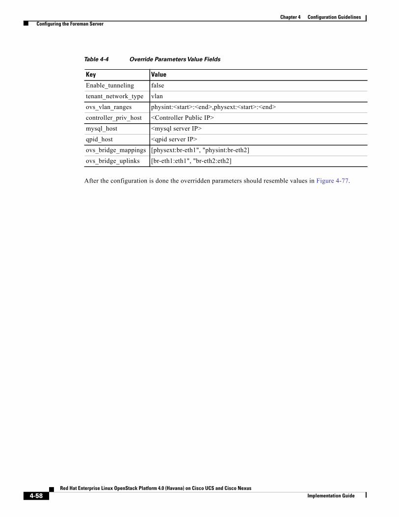
Chapter 4 Configuration GuidelinesConfiguring the Foreman Server
After the configuration is done the overridden parameters should resemble values in Figure 4-77.
Table 4-4 Override Parameters Value Fields
Key Value
Enable_tunneling false
tenant_network_type vlan
ovs_vlan_ranges physint:<start>:<end>,physext:<start>:<end>
controller_priv_host <Controller Public IP>
mysql_host <mysql server IP>
qpid_host <qpid server IP>
ovs_bridge_mappings [physext:br-eth1", "physint:br-eth2]
ovs_bridge_uplinks [br-eth1:eth1", "br-eth2:eth2]
4-58Red Hat Enterprise Linux OpenStack Platform 4.0 (Havana) on Cisco UCS and Cisco Nexus
Implementation Guide
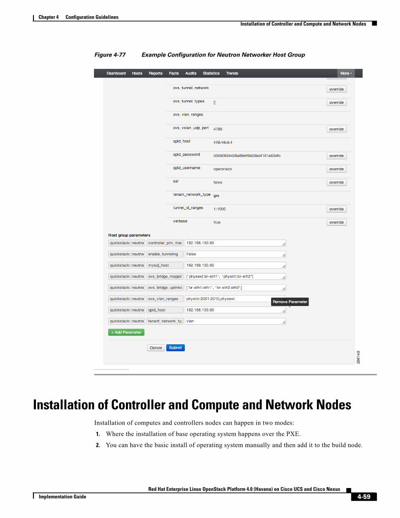
Chapter 4 Configuration GuidelinesInstallation of Controller and Compute and Network Nodes
Figure 4-77 Example Configuration for Neutron Networker Host Group
Installation of Controller and Compute and Network NodesInstallation of computes and controllers nodes can happen in two modes:
1. Where the installation of base operating system happens over the PXE.
2. You can have the basic install of operating system manually and then add it to the build node.
4-59Red Hat Enterprise Linux OpenStack Platform 4.0 (Havana) on Cisco UCS and Cisco Nexus
Implementation Guide
Chapter 4 Configuration GuidelinesInstallation of Controller and Compute and Network Nodes
Installing Nodes via PXE (Provisioning Method)Perform the following procedure to install nodes via PXE (provisioning method).
Step 1 Navigate to the add Host section through the top-level hosts tab on the page.
Installation of Compute, Controller and Network involves common steps.
Step 2 While adding different type of nodes, select the appropriate value under the host group drop down menu. Ex. If you are adding a controller, select Controller (neutron) from the drop down menu of the host group, similarly for compute and network node appropriate values need to be selected.
Step 3 Fill the details on the Name, Network, and Operating System Info from the drop down menus (Figure 4-78). You can use the default values from the drop-down menu until it is specified here to use a custom value (Values like IPs would be filled according to your network settings).
Step 4 Under the Network tab, provide the MAC address of the to-be compute, controller and network nodes that are required to installed via PXE boot.
Step 5 Under the Operating System tab, you can set the root password for the Operating system and also verify if the provisioning templates are configured properly, by clicking on the Resolve button. For configuring the provisioning templates refer to Configure Provisioning Template, page 4-51.
Workaround
The Add interface on the foreman UI is non-functional. Hence we need to add interface either manually after the Node is provisioned else add it to the PXE template to automate it.
• Manual Solution—After the nodes are installed, manually go to each compute Node and Networker node and manually configure the "eth2" by editing the "/etc/sysconfig/network-scripts/ifcfg-eth2" and bring it up command "ifconfig eth2 up".
• Automated Solution—Edit the Openstack PXE template under the Provision Templates section in Foreman to add the following line in the kickstart file defined there.
network --onboot yes --device eth2 --bootproto static --ip "<%[email protected]['priv_ip'] %>" --netmask 255.255.255.0 --noipv6--hostname <%= @host %> ‹nodefroute
4-60Red Hat Enterprise Linux OpenStack Platform 4.0 (Havana) on Cisco UCS and Cisco Nexus
Implementation Guide
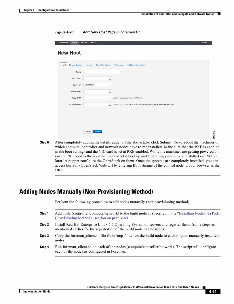
Chapter 4 Configuration GuidelinesInstallation of Controller and Compute and Network Nodes
Figure 4-78 Add New Host Page in Foreman UI
Step 6 After completely adding the details under all the above tabs, click Submit. Now, reboot the machines on which compute, controller and network nodes have to me installed. Make sure that the PXE is enabled in the boot settings and the NIC card is set at PXE enabled. While the machines are getting powered on, ensure PXE boot as the boot method and let it boot up and Operating system to be installed via PXE and later let puppet configure the OpenStack on them. Once the systems are completely installed, you can access horizon (OpenStack Web-UI) by entering IP/hostname of the control node in your browser as the URL.
Adding Nodes Manually (Non-Provisioning Method)Perform the following procedure to add nodes manually (non-provisioning method).
Step 1 Add hosts (controller/compute/network) to the build node as specified in the “Installing Nodes via PXE (Provisioning Method)” section on page 4-60.
Step 2 Install Red Hat Enterprise Linux 6.5 Operating System on servers and register them. (same steps as mentioned earlier for the registration of the build node can be used).
Step 3 Copy the foreman_client.sh file from /tmp folder on the build node to each of your manually installed nodes.
Step 4 Run foreman_client.sh on each of the nodes (compute/controller/network). The script will configure each of the nodes as configured in Foreman.
4-61Red Hat Enterprise Linux OpenStack Platform 4.0 (Havana) on Cisco UCS and Cisco Nexus
Implementation Guide
Chapter 4 Configuration GuidelinesInstallation of Controller and Compute and Network Nodes
Workaround for Known Bugs after Installing NodesOn the network node there is a workaround for known issues.
The following is a workaround for Bug Red Hat Bugzilla 1080646.
• Edit the file /etc/neturon/metadata_agent.ini by adding the following:admin_tenant_name = %SERVICE_TENANT_NAME%admin_user = %SERVICE_USER%admin_password = %SERVICE_PASSWORD%
Workaround for Isolating MetadataOn the network node there is a workaround for isolating metadata.
• Edit the file /etc/neutron/dhcp_agent.ini to:enable_isolated_metadata = True
Workaround for Correcting the Neutron init-script for the Cisco Neutron PluginOn the controller node there is a workaround for correcting the neutron init-script for the Cisco Neutron plugin to work properly.
• Edit the file /etc/init.d/neutron-server by replacing the configuration as follows:#!/bin/bash## neutron OpenStack Software Defined Networking Service## chkconfig: - 9802# description: neutron provides an API to \# * request and configure virtual networks### END INIT INFO
. /etc/rc.d/init.d/functions
prog=neutron# jtaleric Added the line below:plugin=ciscoexec="/usr/bin/$prog-server"dbcheck="/usr/bin/$prog-db-check"configs=(
"/usr/share/$prog/$prog-dist.conf"\"/etc/$prog/$prog.conf"\
# jtaleric Added the line below:"/etc/$prog/plugins/$plugin/cisco_plugins.ini"\"/etc/$prog/plugin.ini"\
4-62Red Hat Enterprise Linux OpenStack Platform 4.0 (Havana) on Cisco UCS and Cisco Nexus
Implementation Guide
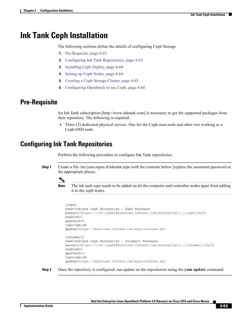
Chapter 4 Configuration GuidelinesInk Tank Ceph Installation
Ink Tank Ceph InstallationThe following sections define the details of configuring Ceph Storage.
1. Pre-Requisite, page 4-63
2. Configuring Ink Tank Repositories, page 4-63
3. Installing Ceph Deploy, page 4-64
4. Setting up Ceph Nodes, page 4-64
5. Creating a Ceph Storage Cluster, page 4-65
6. Configuring OpenStack to use Ceph, page 4-66
Pre-RequisiteAn Ink Tank subscription [http://www.inktank.com] is necessary to get the supported packages from their repository. The following is required:
• Three (3) dedicated physical servers. One for the Ceph-mon node and other two working as a Ceph-OSD node.
Configuring Ink Tank RepositoriesPerform the following procedure to configure Ink Tank repositories.
Step 1 Create a file /etc/yum.repos.d/inktank.repo with the contents below [replace the username/password at the appropriate places.
Note The ink tank repo needs to be added on all the computer and controller nodes apart from adding it to the ceph nodes.
[ceph]name=Inktank Ceph Enterprise - Ceph Packagesbaseurl=https://{id}:{pwd}@download.inktank.com/enterprise/1.1/ceph/rhel6enabled=1gpgcheck=1type=rpm-mdgpgkey=https://download.inktank.com/keys/release.asc
[calamari]name=Inktank Ceph Enterprise - Calamari Packagesbaseurl=https://{id}:{pwd}@download.inktank.com/enterprise/1.1/calamari/rhel6enabled=1gpgcheck=1type=rpm-mdgpgkey=https://download.inktank.com/keys/release.asc
Step 2 Once the repository is configured, run update on the repositories using the yum update command.
4-63Red Hat Enterprise Linux OpenStack Platform 4.0 (Havana) on Cisco UCS and Cisco Nexus
Implementation Guide
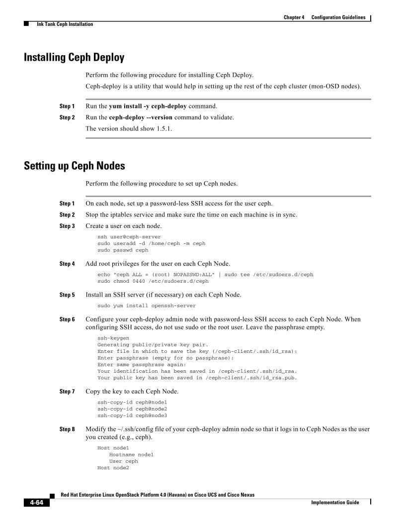
Chapter 4 Configuration GuidelinesInk Tank Ceph Installation
Installing Ceph DeployPerform the following procedure for installing Ceph Deploy.
Ceph-deploy is a utility that would help in setting up the rest of the ceph cluster (mon-OSD nodes).
Step 1 Run the yum install -y ceph-deploy command.
Step 2 Run the ceph-deploy --version command to validate.
The version should show 1.5.1.
Setting up Ceph NodesPerform the following procedure to set up Ceph nodes.
Step 1 On each node, set up a password-less SSH access for the user ceph.
Step 2 Stop the iptables service and make sure the time on each machine is in sync.
Step 3 Create a user on each node.ssh user@ceph-serversudo useradd -d /home/ceph -m cephsudo passwd ceph
Step 4 Add root privileges for the user on each Ceph Node.echo "ceph ALL = (root) NOPASSWD:ALL" | sudo tee /etc/sudoers.d/cephsudo chmod 0440 /etc/sudoers.d/ceph
Step 5 Install an SSH server (if necessary) on each Ceph Node.sudo yum install openssh-server
Step 6 Configure your ceph-deploy admin node with password-less SSH access to each Ceph Node. When configuring SSH access, do not use sudo or the root user. Leave the passphrase empty.
ssh-keygenGenerating public/private key pair.Enter file in which to save the key (/ceph-client/.ssh/id_rsa):Enter passphrase (empty for no passphrase):Enter same passphrase again:Your identification has been saved in /ceph-client/.ssh/id_rsa.Your public key has been saved in /ceph-client/.ssh/id_rsa.pub.
Step 7 Copy the key to each Ceph Node.ssh-copy-id ceph@node1ssh-copy-id ceph@node2ssh-copy-id ceph@node3
Step 8 Modify the ~/.ssh/config file of your ceph-deploy admin node so that it logs in to Ceph Nodes as the user you created (e.g., ceph).
Host node1Hostname node1User ceph
Host node2
4-64Red Hat Enterprise Linux OpenStack Platform 4.0 (Havana) on Cisco UCS and Cisco Nexus
Implementation Guide
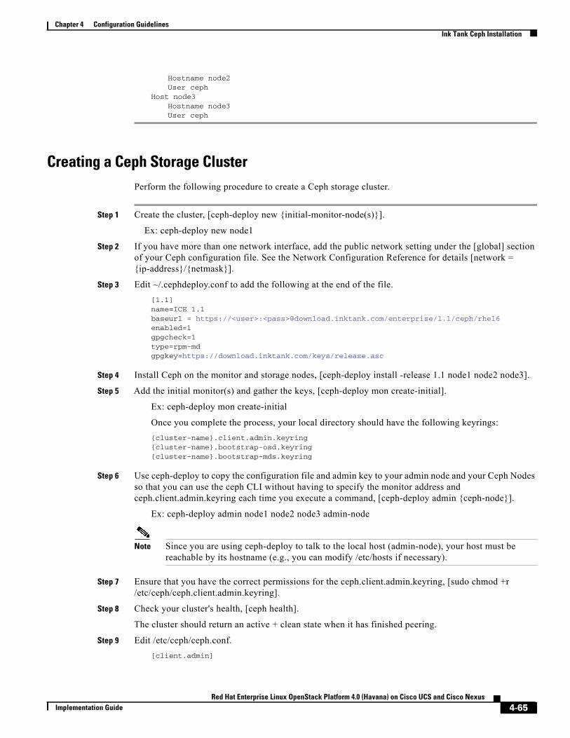
Chapter 4 Configuration GuidelinesInk Tank Ceph Installation
Hostname node2User ceph
Host node3Hostname node3User ceph
Creating a Ceph Storage ClusterPerform the following procedure to create a Ceph storage cluster.
Step 1 Create the cluster, [ceph-deploy new {initial-monitor-node(s)}].
Ex: ceph-deploy new node1
Step 2 If you have more than one network interface, add the public network setting under the [global] section of your Ceph configuration file. See the Network Configuration Reference for details [network = {ip-address}/{netmask}].
Step 3 Edit ~/.cephdeploy.conf to add the following at the end of the file.[1.1]name=ICE 1.1baseurl = https://<user>:<pass>@download.inktank.com/enterprise/1.1/ceph/rhel6enabled=1gpgcheck=1type=rpm-mdgpgkey=https://download.inktank.com/keys/release.asc
Step 4 Install Ceph on the monitor and storage nodes, [ceph-deploy install -release 1.1 node1 node2 node3].
Step 5 Add the initial monitor(s) and gather the keys, [ceph-deploy mon create-initial].
Ex: ceph-deploy mon create-initial
Once you complete the process, your local directory should have the following keyrings:{cluster-name}.client.admin.keyring{cluster-name}.bootstrap-osd.keyring{cluster-name}.bootstrap-mds.keyring
Step 6 Use ceph-deploy to copy the configuration file and admin key to your admin node and your Ceph Nodes so that you can use the ceph CLI without having to specify the monitor address and ceph.client.admin.keyring each time you execute a command, [ceph-deploy admin {ceph-node}].
Ex: ceph-deploy admin node1 node2 node3 admin-node
Note Since you are using ceph-deploy to talk to the local host (admin-node), your host must be reachable by its hostname (e.g., you can modify /etc/hosts if necessary).
Step 7 Ensure that you have the correct permissions for the ceph.client.admin.keyring, [sudo chmod +r /etc/ceph/ceph.client.admin.keyring].
Step 8 Check your cluster's health, [ceph health].
The cluster should return an active + clean state when it has finished peering.
Step 9 Edit /etc/ceph/ceph.conf.[client.admin]
4-65Red Hat Enterprise Linux OpenStack Platform 4.0 (Havana) on Cisco UCS and Cisco Nexus
Implementation Guide
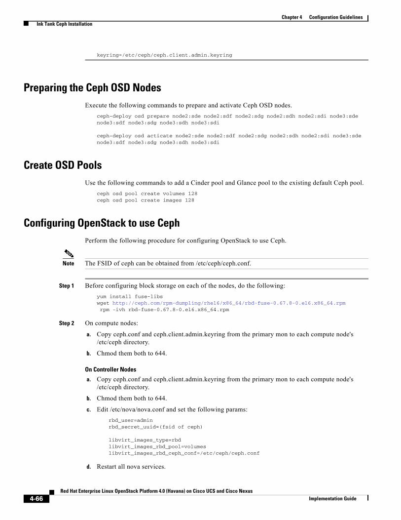
Chapter 4 Configuration GuidelinesInk Tank Ceph Installation
keyring=/etc/ceph/ceph.client.admin.keyring
Preparing the Ceph OSD NodesExecute the following commands to prepare and activate Ceph OSD nodes.
ceph-deploy osd prepare node2:sde node2:sdf node2:sdg node2:sdh node2:sdi node3:sdenode3:sdf node3:sdg node3:sdh node3:sdi
ceph-deploy osd acticate node2:sde node2:sdf node2:sdg node2:sdh node2:sdi node3:sdenode3:sdf node3:sdg node3:sdh node3:sdi
Create OSD PoolsUse the following commands to add a Cinder pool and Glance pool to the existing default Ceph pool.
ceph osd pool create volumes 128ceph osd pool create images 128
Configuring OpenStack to use CephPerform the following procedure for configuring OpenStack to use Ceph.
Note The FSID of ceph can be obtained from /etc/ceph/ceph.conf.
Step 1 Before configuring block storage on each of the nodes, do the following:yum install fuse-libswget http://ceph.com/rpm-dumpling/rhel6/x86_64/rbd-fuse-0.67.8-0.el6.x86_64.rpmrpm -ivh rbd-fuse-0.67.8-0.el6.x86_64.rpm
Step 2 On compute nodes:
a. Copy ceph.conf and ceph.client.admin.keyring from the primary mon to each compute node's /etc/ceph directory.
b. Chmod them both to 644.
On Controller Nodes
a. Copy ceph.conf and ceph.client.admin.keyring from the primary mon to each compute node's /etc/ceph directory.
b. Chmod them both to 644.
c. Edit /etc/nova/nova.conf and set the following params:rbd_user=adminrbd_secret_uuid=(fsid of ceph)
libvirt_images_type=rbdlibvirt_images_rbd_pool=volumeslibvirt_images_rbd_ceph_conf=/etc/ceph/ceph.conf
d. Restart all nova services.
4-66Red Hat Enterprise Linux OpenStack Platform 4.0 (Havana) on Cisco UCS and Cisco Nexus
Implementation Guide
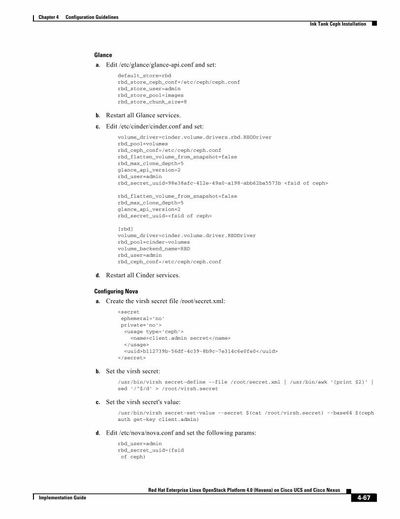
Chapter 4 Configuration GuidelinesInk Tank Ceph Installation
Glance
a. Edit /etc/glance/glance-api.conf and set:default_store=rbdrbd_store_ceph_conf=/etc/ceph/ceph.confrbd_store_user=adminrbd_store_pool=imagesrbd_store_chunk_size=8
b. Restart all Glance services.
c. Edit /etc/cinder/cinder.conf and set:volume_driver=cinder.volume.drivers.rbd.RBDDriverrbd_pool=volumesrbd_ceph_conf=/etc/ceph/ceph.confrbd_flatten_volume_from_snapshot=falserbd_max_clone_depth=5glance_api_version=2rbd_user=adminrbd_secret_uuid=98e38afc-412e-49a0-a198-abb62ba5573b <fsid of ceph>
rbd_flatten_volume_from_snapshot=falserbd_max_clone_depth=5glance_api_version=2rbd_secret_uuid=<fsid of ceph>
[rbd]volume_driver=cinder.volume.driver.RBDDriverrbd_pool=cinder-volumesvolume_backend_name=RBDrbd_user=adminrbd_ceph_conf=/etc/ceph/ceph.conf
d. Restart all Cinder services.
Configuring Nova
a. Create the virsh secret file /root/secret.xml:<secretephemeral='no'private='no'><usage type='ceph'>
<name>client.admin secret</name></usage><uuid>b112739b-56df-4c39-8b9c-7e314c6e0fe0</uuid>
</secret>
b. Set the virsh secret:/usr/bin/virsh secret-define --file /root/secret.xml | /usr/bin/awk '{print $2}' |sed '/^$/d' > /root/virsh.secret
c. Set the virsh secret's value:/usr/bin/virsh secret-set-value --secret $(cat /root/virsh.secret) --base64 $(cephauth get-key client.admin)
d. Edit /etc/nova/nova.conf and set the following params:rbd_user=adminrbd_secret_uuid=(fsidof ceph)
4-67Red Hat Enterprise Linux OpenStack Platform 4.0 (Havana) on Cisco UCS and Cisco Nexus
Implementation Guide
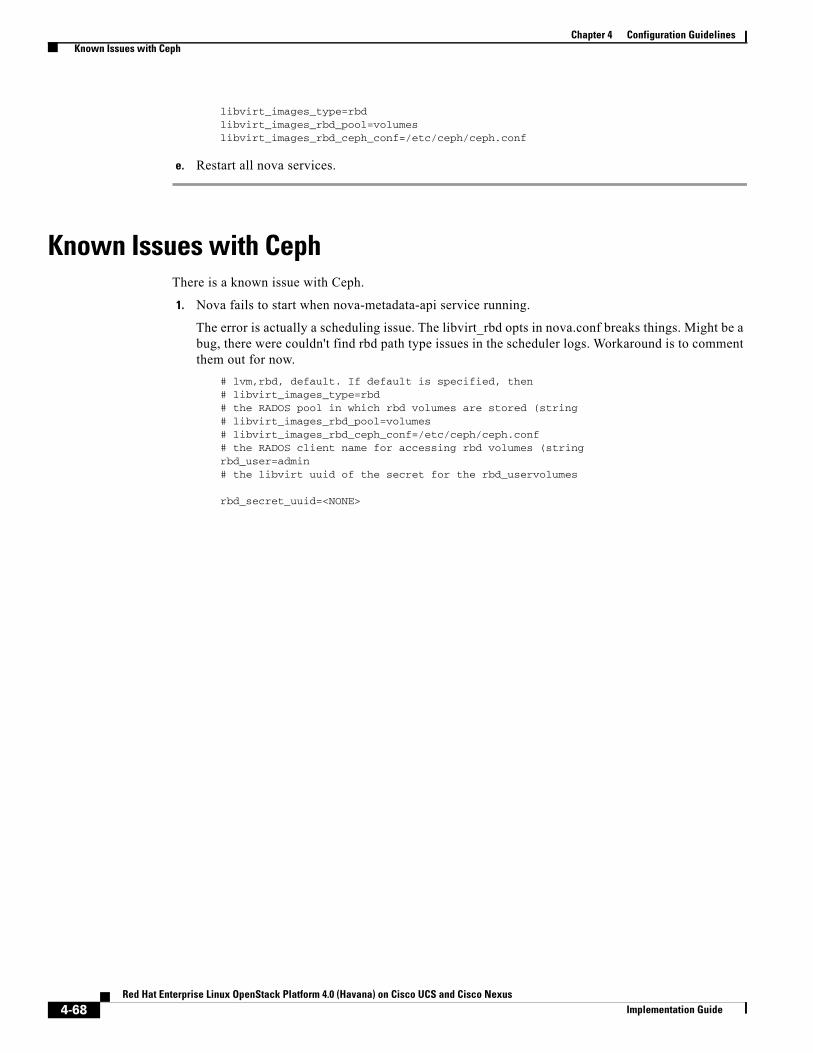
Chapter 4 Configuration GuidelinesKnown Issues with Ceph
libvirt_images_type=rbdlibvirt_images_rbd_pool=volumeslibvirt_images_rbd_ceph_conf=/etc/ceph/ceph.conf
e. Restart all nova services.
Known Issues with CephThere is a known issue with Ceph.
1. Nova fails to start when nova-metadata-api service running.
The error is actually a scheduling issue. The libvirt_rbd opts in nova.conf breaks things. Might be a bug, there were couldn't find rbd path type issues in the scheduler logs. Workaround is to comment them out for now.
# lvm,rbd, default. If default is specified, then# libvirt_images_type=rbd# the RADOS pool in which rbd volumes are stored (string# libvirt_images_rbd_pool=volumes# libvirt_images_rbd_ceph_conf=/etc/ceph/ceph.conf# the RADOS client name for accessing rbd volumes (stringrbd_user=admin# the libvirt uuid of the secret for the rbd_uservolumes
rbd_secret_uuid=<NONE>
4-68Red Hat Enterprise Linux OpenStack Platform 4.0 (Havana) on Cisco UCS and Cisco Nexus
Implementation Guide

Red Hat Enterprise Linux OpenStack PlatformImplementation Guide
A
P P E N D I X A CaveatsThe following known caveats are available for consideration accompanied by defect ID’s.
1. Bug ID 1087571—The commands which have been introduced in neutron client version 2.3.4 may fail.
2. Bug ID 1087574—The service openstack-cinder-volume may fail to start automatically after a reboot of the control server. To work around this, start the service manually after every reboot, or use the following command to enable autostart:chkconfig openstack-cinder-volume on
3. Bug ID 1087576—The snapshot feature may fail with the error libvirtError: unsupported configuration: block copy is not supported with this QEMU binary.
4. Bug ID 1087579—The feature Boot from image (Create a new volume) may fail with the error Instance failed block device setup.
A-14.0 (Havana) on Cisco UCS and Cisco Nexus

Appendix A Caveats
A-2Red Hat Enterprise Linux OpenStack Platform 4.0 (Havana) on Cisco UCS and Cisco Nexus
Implementation Guide

Red Hat Enterprise Linux OpenStack PlatformImplementation Guide
A
P P E N D I X B Bill of MaterialsTable B-1 lists components used in the implementation of a 250 virtual machines configuration.
For more information on details of the hardware components, refer to: http://www.cisco.com/en/US/prod/collateral/ps10265/ps10493/C220M3_SFF_SpecSheet.pdf
Table B-1 List of Hardware Components
Device Description
6 x Cisco UCS C220M3 Rack Servers UCSC-C220-M3S
3 x Cisco UCS C240M3 Rack Servers
CPU for C220M3 Rack Servers (2 per server) UCS-CPU-E5-2650
CPU for C240M3 Rack Servers (2 per server)
Memory for C220M3/ C240M3 Rack Servers (8 per server) UCS-MR-1X162RY-A
Cisco UCS 1225 VIC Adapter (1 per server) UCSC-PCIE-CSC-02
UCS 2232PP Fabric Extenders (2) N2K-C2232PP-10GE
UCS 6248UP Fabric Interconnects (2) UCS-FI-6248UP
10 Gbps SFP+ multifiber mode SFP-10G-SR
2 Cisco Nexus 3064 Top of Rack Switch Cisco Nexus® 3064-X
B-14.0 (Havana) on Cisco UCS and Cisco Nexus

Appendix B Bill of Materials
B-2Red Hat Enterprise Linux OpenStack Platform 4.0 (Havana) on Cisco UCS and Cisco Nexus
Implementation Guide
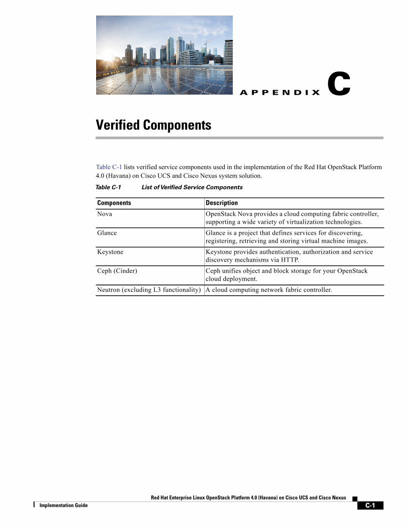
Red Hat Enterprise Linux OpenStack PlatformImplementation Guide
A
P P E N D I X C Verified ComponentsTable C-1 lists verified service components used in the implementation of the Red Hat OpenStack Platform 4.0 (Havana) on Cisco UCS and Cisco Nexus system solution.
Table C-1 List of Verified Service Components
Components Description
Nova OpenStack Nova provides a cloud computing fabric controller, supporting a wide variety of virtualization technologies.
Glance Glance is a project that defines services for discovering, registering, retrieving and storing virtual machine images.
Keystone Keystone provides authentication, authorization and service discovery mechanisms via HTTP.
Ceph (Cinder) Ceph unifies object and block storage for your OpenStack cloud deployment.
Neutron (excluding L3 functionality) A cloud computing network fabric controller.
C-14.0 (Havana) on Cisco UCS and Cisco Nexus

Appendix C Verified Components
C-2Red Hat Enterprise Linux OpenStack Platform 4.0 (Havana) on Cisco UCS and Cisco Nexus
Implementation Guide