
Red Hat Enterprise Linux 4 Virtual Server Administration
59
Landmann Red Hat Enterprise Linux 4 Virtual Server Administration Linux Virtual Server (LVS) for Red Hat Enterprise Linux Edition 1.0
Transcript of Red Hat Enterprise Linux 4 Virtual Server Administration

Landmann
Red Hat Enterprise Linux 4Virtual Server Administration
Linux Virtual Server (LVS) for Red Hat Enterprise LinuxEdition 1.0

Red Hat Enterprise Linux 4 Virtual Server Administration
Linux Virtual Server (LVS) for Red Hat Enterprise LinuxEdition 1.0

Legal Notice
Copyright © 2009 Red Hat, Inc.
This document is licensed by Red Hat under the Creative Commons Attribution-ShareAlike 3.0 UnportedLicense. If you distribute this document, or a modified version of it, you must provide attribution to RedHat, Inc. and provide a link to the original. If the document is modified, all Red Hat trademarks must beremoved.
Red Hat, as the licensor of this document, waives the right to enforce, and agrees not to assert, Section4d of CC-BY-SA to the fullest extent permitted by applicable law.
Red Hat, Red Hat Enterprise Linux, the Shadowman logo, JBoss, MetaMatrix, Fedora, the Infinity Logo,and RHCE are trademarks of Red Hat, Inc., registered in the United States and other countries.
Linux ® is the registered trademark of Linus Torvalds in the United States and other countries.
Java ® is a registered trademark of Oracle and/or its affiliates.
XFS ® is a trademark of Silicon Graphics International Corp. or its subsidiaries in the United Statesand/or other countries.
MySQL ® is a registered trademark of MySQL AB in the United States, the European Union and othercountries.
Node.js ® is an official trademark of Joyent. Red Hat Software Collections is not formally related to orendorsed by the official Joyent Node.js open source or commercial project.
The OpenStack ® Word Mark and OpenStack Logo are either registered trademarks/service marks ortrademarks/service marks of the OpenStack Foundation, in the United States and other countries andare used with the OpenStack Foundation's permission. We are not affiliated with, endorsed orsponsored by the OpenStack Foundation, or the OpenStack community.
All other trademarks are the property of their respective owners.
Abstract
Building a Linux Virtual Server (LVS) system offers highly-available and scalable solution for productionservices using specialized routing and load-balancing techniques configured through the PIRANHA. Thisbook discusses the configuration of high-performance systems and services with Red Hat EnterpriseLinux 4 and LVS.
. . . . . . . . . . . . . . . . . . . . . . . . . . . . . . . . . . . . . . . . . . . . . . . . . . . . . . . . . . . . . . . . . . . . . . . . . . . . . . . . . . . . . . . . . . . . . . . . . . . . . . . . . . . . . . . . . . . . . . . . . . . . . . . . . . . . . . . . . . . . . . . . . . . . . . . . . . . . . . . . . . . . . . . . . . . . . . . . . . . . . . . . . . . . . . . . . . . . . . . . . . . . . . . . . . . . . . . . . . . . . . . . . . . . . . . . . . . . . . . . . . . . . . . . . . . . . . . . . . . . . . . . . . . . . . . . . . . . . . . .
. . . . . . . . . . . . . . . . . . . . . . . . . . . . . . . . . . . . . . . . . . . . . . . . . . . . . . . . . . . . . . . . . . . . . . . . . . . . . . . . . . . . . . . . . . . . . . . . . . . . . . . . . . . . . . . . . . . . . . . . . . . . . . . . . . . . . . . . . . . . . . . . . . . . . . . . . . . . . . . . . . . . . . . . . . . . . . . . . . . . . . . . . . . . . . . . . . . . . . . . . . . . . . . . . . . . . . . . . . . . . . . . . . . . . . . . . . . . . . . . . . . . . . . . . . . . . . . . . . . . . . . . . . . . . . . . . . . . . . . .
. . . . . . . . . . . . . . . . . . . . . . . . . . . . . . . . . . . . . . . . . . . . . . . . . . . . . . . . . . . . . . . . . . . . . . . . . . . . . . . . . . . . . . . . . . . . . . . . . . . . . . . . . . . . . . . . . . . . . . . . . . . . . . . . . . . . . . . . . . . . . . . . . . . . . . . . . . . . . . . . . . . . . . . . . . . . . . . . . . . . . . . . . . . . . . . . . . . . . . . . . . . . . . . . . . . . . . . . . . . . . . . . . . . . . . . . . . . . . . . . . . . . . . . . . . . . . . . . . . . . . . . . . . . . . . . . . . . . . . . .
. . . . . . . . . . . . . . . . . . . . . . . . . . . . . . . . . . . . . . . . . . . . . . . . . . . . . . . . . . . . . . . . . . . . . . . . . . . . . . . . . . . . . . . . . . . . . . . . . . . . . . . . . . . . . . . . . . . . . . . . . . . . . . . . . . . . . . . . . . . . . . . . . . . . . . . . . . . . . . . . . . . . . . . . . . . . . . . . . . . . . . . . . . . . . . . . . . . . . . . . . . . . . . . . . . . . . . . . . . . . . . . . . . . . . . . . . . . . . . . . . . . . . . . . . . . . . . . . . . . . . . . . . . . . . . . . . . . . . . . .
Table of Contents
Introduction1. Document Conventions
1.1. Typographic Conventions1.2. Pull-quote Conventions1.3. Notes and Warnings
2. Feedback
Chapter 1. Linux Virtual Server Overview1.1. A Basic LVS Configuration
1.1.1. Data Replication and Data Sharing Between Real Servers1.1.1.1. Configuring Real Servers to Synchronize Data
1.2. A Three-Tier LVS Configuration1.3. LVS Scheduling Overview
1.3.1. Scheduling Algorithms1.3.2. Server Weight and Scheduling
1.4. Routing Methods1.4.1. NAT Routing1.4.2. Direct Routing
1.4.2.1. Direct Routing and the ARP Limitation1.5. Persistence and Firewall Marks
1.5.1. Persistence1.5.2. Firewall Marks
1.6. LVS — A Block Diagram1.6.1. LVS Components
1.6.1.1. pulse1.6.1.2. lvs1.6.1.3. ipvsadm1.6.1.4. nanny1.6.1.5. /etc/sysconfig/ha/lvs.cf1.6.1.6. Piranha Configuration Tool1.6.1.7. send_arp
Chapter 2. Init ial LVS Configuration2.1. Configuring Services on the LVS Routers2.2. Setting a Password for the Piranha Configuration Tool2.3. Starting the Piranha Configuration Tool Service
2.3.1. Configuring the Piranha Configuration Tool Web Server Port2.4. Limiting Access To the Piranha Configuration Tool2.5. Turning on Packet Forwarding2.6. Configuring Services on the Real Servers
Chapter 3. Sett ing Up LVS3.1. The NAT LVS Network
3.1.1. Configuring Network Interfaces for LVS with NAT3.1.2. Routing on the Real Servers3.1.3. Enabling NAT Routing on the LVS Routers
3.2. LVS via Direct Routing3.2.1. Direct Routing and arptables_jf3.2.2. Direct Routing and iptables
3.3. Putting the Configuration Together3.3.1. General LVS Networking T ips
3.4. Multi-port Services and LVS
455677
99
10101112121314141516161617171818181818181818
2020212122222323
2424242526262728292930
Table of Contents
1
. . . . . . . . . . . . . . . . . . . . . . . . . . . . . . . . . . . . . . . . . . . . . . . . . . . . . . . . . . . . . . . . . . . . . . . . . . . . . . . . . . . . . . . . . . . . . . . . . . . . . . . . . . . . . . . . . . . . . . . . . . . . . . . . . . . . . . . . . . . . . . . . . . . . . . . . . . . . . . . . . . . . . . . . . . . . . . . . . . . . . . . . . . . . . . . . . . . . . . . . . . . . . . . . . . . . . . . . . . . . . . . . . . . . . . . . . . . . . . . . . . . . . . . . . . . . . . . . . . . . . . . . . . . . . . . . . . . . . . . .
. . . . . . . . . . . . . . . . . . . . . . . . . . . . . . . . . . . . . . . . . . . . . . . . . . . . . . . . . . . . . . . . . . . . . . . . . . . . . . . . . . . . . . . . . . . . . . . . . . . . . . . . . . . . . . . . . . . . . . . . . . . . . . . . . . . . . . . . . . . . . . . . . . . . . . . . . . . . . . . . . . . . . . . . . . . . . . . . . . . . . . . . . . . . . . . . . . . . . . . . . . . . . . . . . . . . . . . . . . . . . . . . . . . . . . . . . . . . . . . . . . . . . . . . . . . . . . . . . . . . . . . . . . . . . . . . . . . . . . . .
. . . . . . . . . . . . . . . . . . . . . . . . . . . . . . . . . . . . . . . . . . . . . . . . . . . . . . . . . . . . . . . . . . . . . . . . . . . . . . . . . . . . . . . . . . . . . . . . . . . . . . . . . . . . . . . . . . . . . . . . . . . . . . . . . . . . . . . . . . . . . . . . . . . . . . . . . . . . . . . . . . . . . . . . . . . . . . . . . . . . . . . . . . . . . . . . . . . . . . . . . . . . . . . . . . . . . . . . . . . . . . . . . . . . . . . . . . . . . . . . . . . . . . . . . . . . . . . . . . . . . . . . . . . . . . . . . . . . . . . .
. . . . . . . . . . . . . . . . . . . . . . . . . . . . . . . . . . . . . . . . . . . . . . . . . . . . . . . . . . . . . . . . . . . . . . . . . . . . . . . . . . . . . . . . . . . . . . . . . . . . . . . . . . . . . . . . . . . . . . . . . . . . . . . . . . . . . . . . . . . . . . . . . . . . . . . . . . . . . . . . . . . . . . . . . . . . . . . . . . . . . . . . . . . . . . . . . . . . . . . . . . . . . . . . . . . . . . . . . . . . . . . . . . . . . . . . . . . . . . . . . . . . . . . . . . . . . . . . . . . . . . . . . . . . . . . . . . . . . . . .
3.4.1. Assigning Firewall Marks3.5. Configuring FTP
3.5.1. How FTP Works3.5.2. How This Affects LVS Routing3.5.3. Creating Network Packet Filter Rules
3.5.3.1. Rules for Active Connections3.5.3.2. Rules for Passive Connections
3.6. Saving Network Packet Filter Settings
Chapter 4 . Configuring the LVS Routers with Piranha Configuration Tool4.1. Necessary Software4.2. Logging Into the Piranha Configuration Tool4.3. CONTROL/MONITORING4.4. GLOBAL SETTINGS4.5. REDUNDANCY4.6. VIRTUAL SERVERS
4.6.1. The VIRTUAL SERVER Subsection4.6.2. REAL SERVER Subsection4.6.3. EDIT MONITORING SCRIPTS Subsection
4.7. Synchronizing Configuration Files4.7.1. Synchronizing lvs.cf4.7.2. Synchronizing sysctl4.7.3. Synchronizing Network Packet Filtering Rules
4.8. Starting LVS
Using LVS with Red Hat Cluster
Revision History
IndexSymbolsACDFIJLMNPRSW
3031313232323334
353535363739414144464849495050
51
53
535353535353535454555555565656
Red Hat Enterprise Linux 4 Virtual Server Administration
2

Table of Contents
3

IntroductionThis document provides information about installing, configuring, and managing Red Hat Virtual LinuxServer (LVS) components. LVS provides load balancing through specialized routing techniques thatdispatch traffic to a pool of servers. This document does not include information about installing,configuring, and managing Red Hat Cluster software. Information about that is in a separate document.
The audience of this document should have advanced working knowledge of Red Hat Enterprise Linuxand understand the concepts of clusters, storage, and server computing.
This document is organized as follows:
Chapter 1, Linux Virtual Server OverviewChapter 2, Initial LVS ConfigurationChapter 3, Setting Up LVSChapter 4, Configuring the LVS Routers with Piranha Configuration ToolAppendix A, Using LVS with Red Hat ClusterAppendix B, Revision History
For more information about Red Hat Enterprise Linux 4, refer to the following resources:
Red Hat Enterprise Linux Installation Guide — Provides information regarding installation.
Red Hat Enterprise Linux Introduction to System Administration — Provides introductory informationfor new Red Hat Enterprise Linux system administrators.
Red Hat Enterprise Linux System Administration Guide — Provides more detailed information aboutconfiguring Red Hat Enterprise Linux to suit your particular needs as a user.
Red Hat Enterprise Linux Reference Guide — Provides detailed information suited for moreexperienced users to reference when needed, as opposed to step-by-step instructions.
Red Hat Enterprise Linux Security Guide — Details the planning and the tools involved in creating asecured computing environment for the data center, workplace, and home.
For more information about Red Hat Cluster Suite for Red Hat Enterprise Linux 4, refer to the followingresources:
Red Hat Cluster Suite Overview — Provides a high level overview of the Red Hat Cluster Suite.
Configuring and Managing a Red Hat Cluster — Provides information about installing, configuring andmanaging Red Hat Cluster components.
LVM Administrator's Guide: Configuration and Administration — Provides a description of the LogicalVolume Manager (LVM), including information on running LVM in a clustered environment.
Global File System: Configuration and Administration — Provides information about installing,configuring, and maintaining Red Hat GFS (Red Hat Global File System).
Using Device-Mapper Multipath — Provides information about using the Device-Mapper Multipathfeature of Red Hat Enterprise Linux 4.
Using GNBD with Global File System — Provides an overview on using Global Network Block Device(GNBD) with Red Hat GFS.
Red Hat Cluster Suite Release Notes — Provides information about the current release of Red HatCluster Suite.
Red Hat Cluster Suite documentation and other Red Hat documents are available in HTML, PDF, andRPM versions on the Red Hat Enterprise Linux Documentation CD and online athttp://www.redhat.com/docs/.
Red Hat Enterprise Linux 4 Virtual Server Administration
4

1. Document ConventionsThis manual uses several conventions to highlight certain words and phrases and draw attention tospecific pieces of information.
In PDF and paper editions, this manual uses typefaces drawn from the Liberation Fonts set. TheLiberation Fonts set is also used in HTML editions if the set is installed on your system. If not, alternativebut equivalent typefaces are displayed. Note: Red Hat Enterprise Linux 5 and later include the LiberationFonts set by default.
1.1. Typographic ConventionsFour typographic conventions are used to call attention to specific words and phrases. Theseconventions, and the circumstances they apply to, are as follows.
Mono-spaced Bold
Used to highlight system input, including shell commands, file names and paths. Also used to highlightkeys and key combinations. For example:
To see the contents of the file my_next_bestselling_novel in your current workingdirectory, enter the cat my_next_bestselling_novel command at the shell promptand press Enter to execute the command.
The above includes a file name, a shell command and a key, all presented in mono-spaced bold and alldistinguishable thanks to context.
Key combinations can be distinguished from an individual key by the plus sign that connects each part ofa key combination. For example:
Press Enter to execute the command.
Press Ctrl+Alt+F2 to switch to a virtual terminal.
The first example highlights a particular key to press. The second example highlights a key combination:a set of three keys pressed simultaneously.
If source code is discussed, class names, methods, functions, variable names and returned valuesmentioned within a paragraph will be presented as above, in mono-spaced bold. For example:
File-related classes include filesystem for file systems, file for files, and dir fordirectories. Each class has its own associated set of permissions.
Proportional Bold
This denotes words or phrases encountered on a system, including application names; dialog box text;labeled buttons; check-box and radio button labels; menu titles and sub-menu titles. For example:
Choose System → Preferences → Mouse from the main menu bar to launch MousePreferences. In the Buttons tab, select the Left-handed mouse check box and clickClose to switch the primary mouse button from the left to the right (making the mousesuitable for use in the left hand).
To insert a special character into a gedit file, choose Applications → Accessories →Character Map from the main menu bar. Next, choose Search → Find… from theCharacter Map menu bar, type the name of the character in the Search field and click
Introduction
5
Next. The character you sought will be highlighted in the Character Table. Double-clickthis highlighted character to place it in the Text to copy field and then click the Copybutton. Now switch back to your document and choose Edit → Paste from the gedit menubar.
The above text includes application names; system-wide menu names and items; application-specificmenu names; and buttons and text found within a GUI interface, all presented in proportional bold and alldistinguishable by context.
Mono-spaced Bold Italic or Proportional Bold Italic
Whether mono-spaced bold or proportional bold, the addition of italics indicates replaceable or variabletext. Italics denotes text you do not input literally or displayed text that changes depending oncircumstance. For example:
To connect to a remote machine using ssh, type ssh [email protected] at a shellprompt. If the remote machine is example.com and your username on that machine isjohn, type ssh [email protected] .
The mount -o remount file-system command remounts the named file system. Forexample, to remount the /home file system, the command is mount -o remount /home.
To see the version of a currently installed package, use the rpm -q package command. Itwill return a result as follows: package-version-release.
Note the words in bold italics above — username, domain.name, file-system, package, version andrelease. Each word is a placeholder, either for text you enter when issuing a command or for textdisplayed by the system.
Aside from standard usage for presenting the title of a work, italics denotes the first use of a new andimportant term. For example:
Publican is a DocBook publishing system.
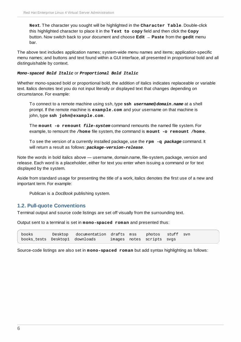
1.2. Pull-quote ConventionsTerminal output and source code listings are set off visually from the surrounding text.
Output sent to a terminal is set in mono-spaced roman and presented thus:
books Desktop documentation drafts mss photos stuff svnbooks_tests Desktop1 downloads images notes scripts svgs
Source-code listings are also set in mono-spaced roman but add syntax highlighting as follows:
Red Hat Enterprise Linux 4 Virtual Server Administration
6

static int kvm_vm_ioctl_deassign_device(struct kvm *kvm, struct kvm_assigned_pci_dev *assigned_dev){ int r = 0; struct kvm_assigned_dev_kernel *match;
mutex_lock(&kvm->lock);
match = kvm_find_assigned_dev(&kvm->arch.assigned_dev_head, assigned_dev->assigned_dev_id); if (!match) { printk(KERN_INFO "%s: device hasn't been assigned before, " "so cannot be deassigned\n", __func__); r = -EINVAL; goto out; }
kvm_deassign_device(kvm, match);
kvm_free_assigned_device(kvm, match);
out: mutex_unlock(&kvm->lock); return r;}
1.3. Notes and WarningsFinally, we use three visual styles to draw attention to information that might otherwise be overlooked.
Note
Notes are tips, shortcuts or alternative approaches to the task at hand. Ignoring a note shouldhave no negative consequences, but you might miss out on a trick that makes your life easier.
Important
Important boxes detail things that are easily missed: configuration changes that only apply to thecurrent session, or services that need restarting before an update will apply. Ignoring a boxlabeled 'Important' will not cause data loss but may cause irritation and frustration.
Warning
Warnings should not be ignored. Ignoring warnings will most likely cause data loss.
2. FeedbackIf you spot a typo, or if you have thought of a way to make this manual better, we would love to hear fromyou. Please submit a report in Bugzilla (http://bugzilla.redhat.com/bugzilla/) against the component rh-cs-en.
Introduction
7

Be sure to mention the manual's identifier:
Virtual_Server_Administration(EN)-4.8 (2009-04-23T15:41)
By mentioning this manual's identifier, we know exactly which version of the guide you have.
If you have a suggestion for improving the documentation, try to be as specific as possible. If you havefound an error, please include the section number and some of the surrounding text so we can find iteasily.
Red Hat Enterprise Linux 4 Virtual Server Administration
8

Chapter 1. Linux Virtual Server OverviewLinux Virtual Server (LVS) is a set of integrated software components for balancing the IP load across aset of real servers. LVS runs on a pair of equally configured computers: one that is an active LVS routerand one that is a backup LVS router. The active LVS router serves two roles:
To balance the load across the real servers.
To check the integrity of the services on each real server.
The backup LVS router monitors the active LVS router and takes over from it in case the active LVSrouter fails.
This chapter provides an overview of LVS components and functions, and consists of the followingsections:
Section 1.1, “A Basic LVS Configuration”
Section 1.2, “A Three-Tier LVS Configuration”
Section 1.3, “LVS Scheduling Overview”
Section 1.4, “Routing Methods”
Section 1.5, “Persistence and Firewall Marks”
Section 1.6, “LVS — A Block Diagram”
1.1. A Basic LVS ConfigurationFigure 1.1, “A Basic LVS Configuration” shows a simple LVS configuration consisting of two layers. Onthe first layer are two LVS routers — one active and one backup. Each of the LVS routers has twonetwork interfaces, one interface on the Internet and one on the private network, enabling them toregulate traffic between the two networks. For this example the active router is using Network AddressTranslation or NAT to direct traffic from the Internet to a variable number of real servers on the secondlayer, which in turn provide the necessary services. Therefore, the real servers in this example areconnected to a dedicated private network segment and pass all public traffic back and forth through theactive LVS router. To the outside world, the servers appears as one entity.
Chapter 1. Linux Virtual Server Overview
9
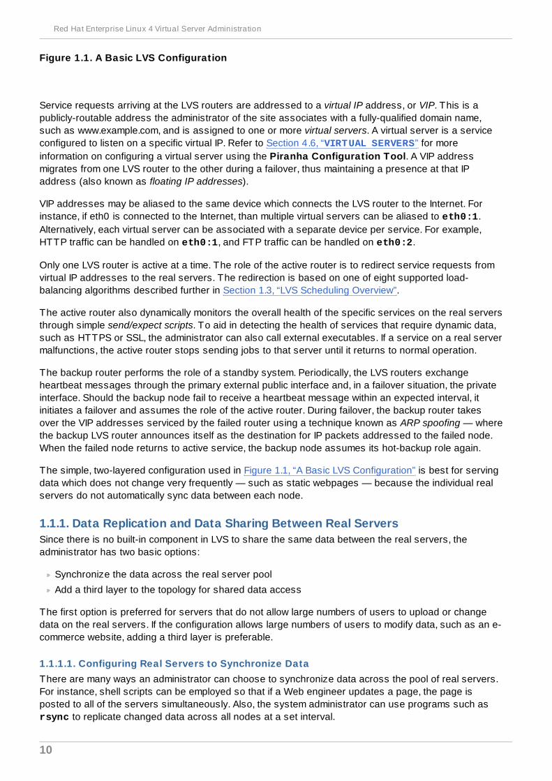
Figure 1.1. A Basic LVS Configuration
Service requests arriving at the LVS routers are addressed to a virtual IP address, or VIP. This is apublicly-routable address the administrator of the site associates with a fully-qualified domain name,such as www.example.com, and is assigned to one or more virtual servers. A virtual server is a serviceconfigured to listen on a specific virtual IP. Refer to Section 4.6, “VIRTUAL SERVERS” for moreinformation on configuring a virtual server using the Piranha Configuration Tool. A VIP addressmigrates from one LVS router to the other during a failover, thus maintaining a presence at that IPaddress (also known as floating IP addresses).
VIP addresses may be aliased to the same device which connects the LVS router to the Internet. Forinstance, if eth0 is connected to the Internet, than multiple virtual servers can be aliased to eth0:1.Alternatively, each virtual server can be associated with a separate device per service. For example,HTTP traffic can be handled on eth0:1, and FTP traffic can be handled on eth0:2.
Only one LVS router is active at a time. The role of the active router is to redirect service requests fromvirtual IP addresses to the real servers. The redirection is based on one of eight supported load-balancing algorithms described further in Section 1.3, “LVS Scheduling Overview”.
The active router also dynamically monitors the overall health of the specific services on the real serversthrough simple send/expect scripts. To aid in detecting the health of services that require dynamic data,such as HTTPS or SSL, the administrator can also call external executables. If a service on a real servermalfunctions, the active router stops sending jobs to that server until it returns to normal operation.
The backup router performs the role of a standby system. Periodically, the LVS routers exchangeheartbeat messages through the primary external public interface and, in a failover situation, the privateinterface. Should the backup node fail to receive a heartbeat message within an expected interval, itinitiates a failover and assumes the role of the active router. During failover, the backup router takesover the VIP addresses serviced by the failed router using a technique known as ARP spoofing — wherethe backup LVS router announces itself as the destination for IP packets addressed to the failed node.When the failed node returns to active service, the backup node assumes its hot-backup role again.
The simple, two-layered configuration used in Figure 1.1, “A Basic LVS Configuration” is best for servingdata which does not change very frequently — such as static webpages — because the individual realservers do not automatically sync data between each node.
1.1.1. Data Replication and Data Sharing Between Real ServersSince there is no built-in component in LVS to share the same data between the real servers, theadministrator has two basic options:
Synchronize the data across the real server pool
Add a third layer to the topology for shared data access
The first option is preferred for servers that do not allow large numbers of users to upload or changedata on the real servers. If the configuration allows large numbers of users to modify data, such as an e-commerce website, adding a third layer is preferable.
1.1.1.1. Configuring Real Servers to Synchronize DataThere are many ways an administrator can choose to synchronize data across the pool of real servers.For instance, shell scripts can be employed so that if a Web engineer updates a page, the page isposted to all of the servers simultaneously. Also, the system administrator can use programs such as rsync to replicate changed data across all nodes at a set interval.
Red Hat Enterprise Linux 4 Virtual Server Administration
10
However, this type of data synchronization does not optimally function if the configuration is overloadedwith users constantly uploading files or issuing database transactions. For a configuration with a highload, a three-tier topology is the ideal solution.
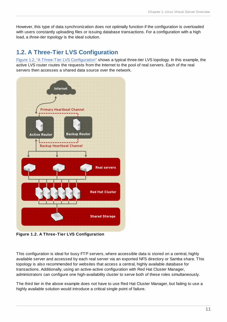
1.2. A Three-Tier LVS ConfigurationFigure 1.2, “A Three-Tier LVS Configuration” shows a typical three-tier LVS topology. In this example, theactive LVS router routes the requests from the Internet to the pool of real servers. Each of the realservers then accesses a shared data source over the network.
Figure 1.2. A Three-Tier LVS Configuration
This configuration is ideal for busy FTP servers, where accessible data is stored on a central, highlyavailable server and accessed by each real server via an exported NFS directory or Samba share. Thistopology is also recommended for websites that access a central, highly available database fortransactions. Additionally, using an active-active configuration with Red Hat Cluster Manager,administrators can configure one high-availability cluster to serve both of these roles simultaneously.
The third tier in the above example does not have to use Red Hat Cluster Manager, but failing to use ahighly available solution would introduce a critical single point of failure.
Chapter 1. Linux Virtual Server Overview
11

1.3. LVS Scheduling OverviewOne of the advantages of using LVS is its ability to perform flexible, IP-level load balancing on the realserver pool. This flexibility is due to the variety of scheduling algorithms an administrator can choosefrom when configuring LVS. LVS load balancing is superior to less flexible methods, such as Round-Robin DNS where the hierarchical nature of DNS and the caching by client machines can lead to loadimbalances. Additionally, the low-level filtering employed by the LVS router has advantages overapplication-level request forwarding because balancing loads at the network packet level causes minimalcomputational overhead and allows for greater scalability.
Using scheduling, the active router can take into account the real servers' activity and, optionally, anadministrator-assigned weight factor when routing service requests. Using assigned weights givesarbitrary priorities to individual machines. Using this form of scheduling, it is possible to create a group ofreal servers using a variety of hardware and software combinations and the active router can evenlyload each real server.
The scheduling mechanism for LVS is provided by a collection of kernel patches called IP Virtual Serveror IPVS modules. These modules enable layer 4 (L4) transport layer switching, which is designed towork well with multiple servers on a single IP address.
To track and route packets to the real servers efficiently, IPVS builds an IPVS table in the kernel. Thistable is used by the active LVS router to redirect requests from a virtual server address to and returningfrom real servers in the pool. The IPVS table is constantly updated by a utility called ipvsadm — addingand removing cluster members depending on their availability.
1.3.1. Scheduling AlgorithmsThe structure that the IPVS table takes depends on the scheduling algorithm that the administratorchooses for any given virtual server. To allow for maximum flexibility in the types of services you cancluster and how these services are scheduled, Red Hat Enterprise Linux provides the followingscheduling algorithms listed below. For instructions on how to assign scheduling algorithms refer toSection 4.6.1, “The VIRTUAL SERVER Subsection”.
Round-Robin SchedulingDistributes each request sequentially around the pool of real servers. Using this algorithm, allthe real servers are treated as equals without regard to capacity or load. This scheduling modelresembles round-robin DNS but is more granular due to the fact that it is network-connectionbased and not host-based. LVS round-robin scheduling also does not suffer the imbalancescaused by cached DNS queries.
Weighted Round-Robin SchedulingDistributes each request sequentially around the pool of real servers but gives more jobs toservers with greater capacity. Capacity is indicated by a user-assigned weight factor, which isthen adjusted upward or downward by dynamic load information. Refer to Section 1.3.2, “ServerWeight and Scheduling” for more on weighting real servers.
Weighted round-robin scheduling is a preferred choice if there are significant differences in thecapacity of real servers in the pool. However, if the request load varies dramatically, the moreheavily weighted server may answer more than its share of requests.
Least-ConnectionDistributes more requests to real servers with fewer active connections. Because it keeps trackof live connections to the real servers through the IPVS table, least-connection is a type of
Red Hat Enterprise Linux 4 Virtual Server Administration
12
dynamic scheduling algorithm, making it a better choice if there is a high degree of variation inthe request load. It is best suited for a real server pool where each member node has roughlythe same capacity. If a group of servers have different capabilities, weighted least-connectionscheduling is a better choice.
Weighted Least-Connections (default)Distributes more requests to servers with fewer active connections relative to their capacities.Capacity is indicated by a user-assigned weight, which is then adjusted upward or downwardby dynamic load information. The addition of weighting makes this algorithm ideal when the realserver pool contains hardware of varying capacity. Refer to Section 1.3.2, “Server Weight andScheduling” for more on weighting real servers.
Locality-Based Least-Connection SchedulingDistributes more requests to servers with fewer active connections relative to their destinationIPs. This algorithm is designed for use in a proxy-cache server cluster. It routes the packets foran IP address to the server for that address unless that server is above its capacity and has aserver in its half load, in which case it assigns the IP address to the least loaded real server.
Locality-Based Least-Connection Scheduling with Replication SchedulingDistributes more requests to servers with fewer active connections relative to their destinationIPs. This algorithm is also designed for use in a proxy-cache server cluster. It differs fromLocality-Based Least-Connection Scheduling by mapping the target IP address to a subset ofreal server nodes. Requests are then routed to the server in this subset with the lowestnumber of connections. If all the nodes for the destination IP are above capacity, it replicates anew server for that destination IP address by adding the real server with the least connectionsfrom the overall pool of real servers to the subset of real servers for that destination IP. Themost loaded node is then dropped from the real server subset to prevent over-replication.
Destination Hash SchedulingDistributes requests to the pool of real servers by looking up the destination IP in a static hashtable. This algorithm is designed for use in a proxy-cache server cluster.
Source Hash SchedulingDistributes requests to the pool of real servers by looking up the source IP in a static hashtable. This algorithm is designed for LVS routers with multiple firewalls.
1.3.2. Server Weight and SchedulingThe administrator of LVS can assign a weight to each node in the real server pool. This weight is aninteger value which is factored into any weight-aware scheduling algorithms (such as weighted least-connections) and helps the LVS router more evenly load hardware with different capabilities.
Weights work as a ratio relative to one another. For instance, if one real server has a weight of 1 and theother server has a weight of 5, then the server with a weight of 5 gets 5 connections for every 1connection the other server gets. The default value for a real server weight is 1.
Although adding weight to varying hardware configurations in a real server pool can help load-balancethe cluster more efficiently, it can cause temporary imbalances when a real server is introduced to thereal server pool and the virtual server is scheduled using weighted least-connections. For example,
Chapter 1. Linux Virtual Server Overview
13
suppose there are three servers in the real server pool. Servers A and B are weighted at 1 and the third,server C, is weighted at 2. If server C goes down for any reason, servers A and B evenly distributes theabandoned load. However, once server C comes back online, the LVS router sees it has zeroconnections and floods the server with all incoming requests until it is on par with servers A and B.
To prevent this phenomenon, administrators can make the virtual server a quiesce server — anytime anew real server node comes online, the least-connections table is reset to zero and the LVS routerroutes requests as if all the real servers were newly added to the cluster.
1.4. Routing MethodsRed Hat Enterprise Linux uses Network Address Translation or NAT routing for LVS, which allows theadministrator tremendous flexibility when utilizing available hardware and integrating the LVS into anexisting network.
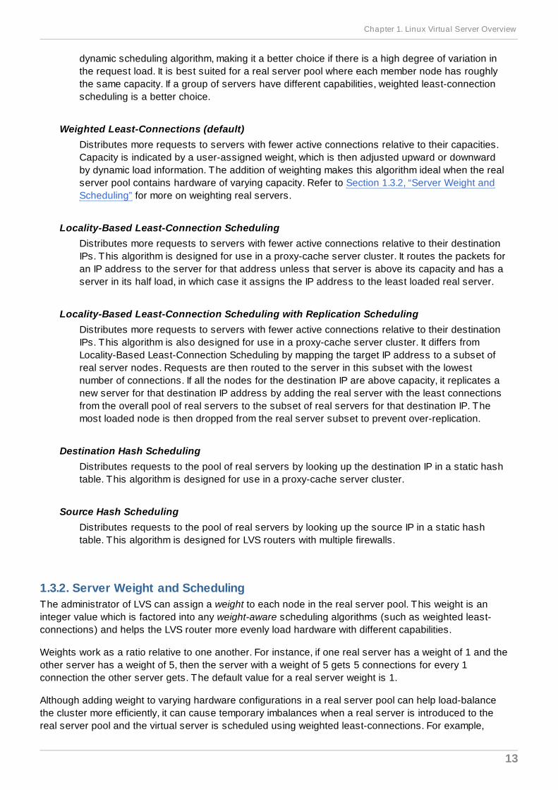
1.4.1. NAT RoutingFigure 1.3, “LVS Implemented with NAT Routing”, illustrates LVS utilizing NAT routing to move requestsbetween the Internet and a private network.
Figure 1.3. LVS Implemented with NAT Routing
In the example, there are two NICs in the active LVS router. The NIC for the Internet has a real IPaddress on eth0 and has a floating IP address aliased to eth0:1. The NIC for the private networkinterface has a real IP address on eth1 and has a floating IP address aliased to eth1:1. In the event offailover, the virtual interface facing the Internet and the private facing virtual interface are taken-over bythe backup LVS router simultaneously. All of the real servers located on the private network use thefloating IP for the NAT router as their default route to communicate with the active LVS router so thattheir abilities to respond to requests from the Internet is not impaired.
In this example, the LVS router's public LVS floating IP address and private NAT floating IP address arealiased to two physical NICs. While it is possible to associate each floating IP address to its own
Red Hat Enterprise Linux 4 Virtual Server Administration
14
physical device on the LVS router nodes, having more than two NICs is not a requirement.
Using this topology, the active LVS router receives the request and routes it to the appropriate server.The real server then processes the request and returns the packets to the LVS router which usesnetwork address translation to replace the address of the real server in the packets with the LVS routerspublic VIP address. This process is called IP masquerading because the actual IP addresses of the realservers is hidden from the requesting clients.
Using this NAT routing, the real servers may be any kind of machine running various operating systems.The main disadvantage is that the LVS router may become a bottleneck in large cluster deploymentsbecause it must process outgoing as well as incoming requests.
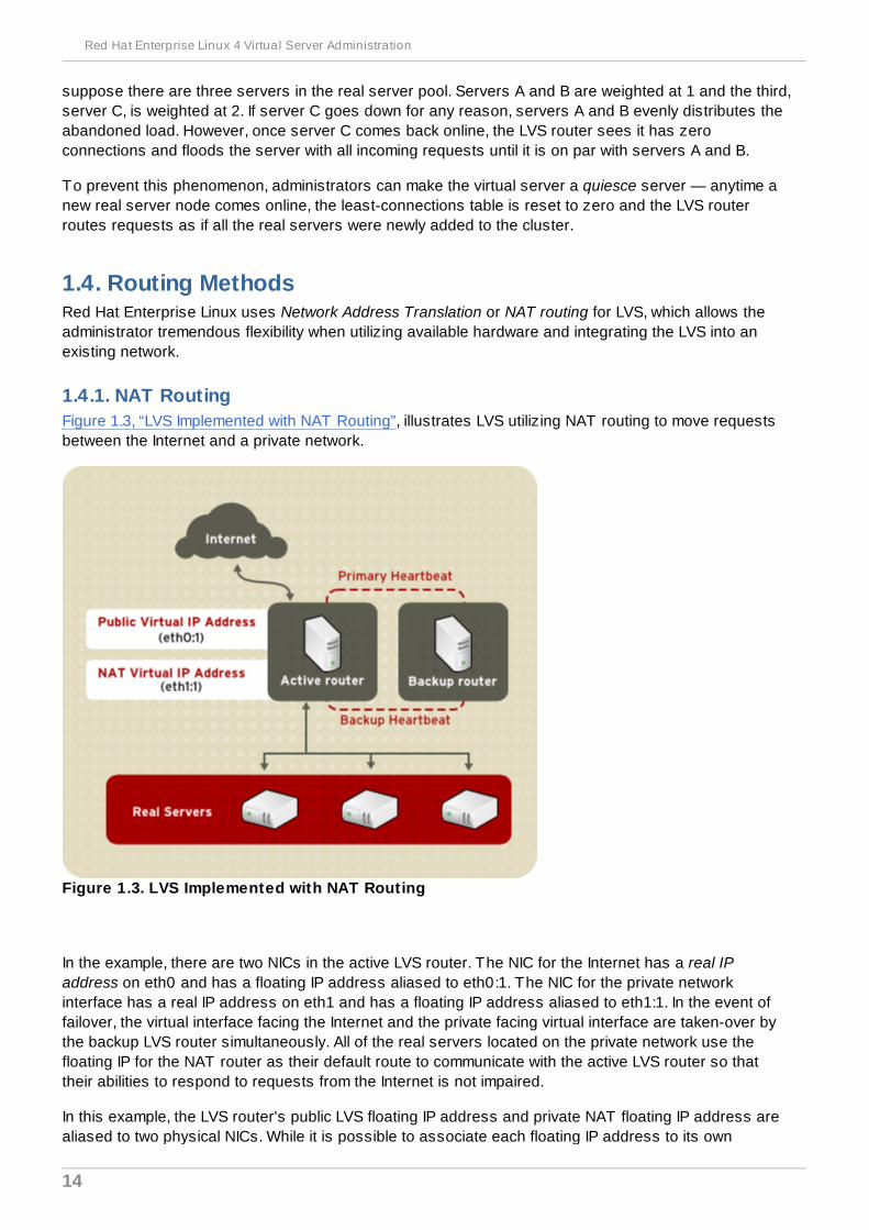
1.4.2. Direct RoutingBuilding an LVS setup that uses direct routing provides increased performance benefits compared toother LVS networking topologies. Direct routing allows the real servers to process and route packetsdirectly to a requesting user rather than passing all outgoing packets through the LVS router. Directrouting reduces the possibility of network performance issues by relegating the job of the LVS router toprocessing incoming packets only.
Figure 1.4 . LVS Implemented with Direct Routing
In the typical direct routing LVS setup, the LVS router receives incoming server requests through thevirtual IP (VIP) and uses a scheduling algorithm to route the request to the real servers. The real serverprocesses the request and sends the response directly to the client, bypassing the LVS routers. Thismethod of routing allows for scalability in that real servers can be added without the added burden onthe LVS router to route outgoing packets from the real server to the client, which can become a
Chapter 1. Linux Virtual Server Overview
15
bottleneck under heavy network load.
1.4 .2.1. Direct Routing and the ARP LimitationWhile there are many advantages to using direct routing in LVS, there are limitations as well. The mostcommon issue with LVS via direct routing is with Address Resolution Protocol (ARP).
In typical situations, a client on the Internet sends a request to an IP address. Network routers typicallysend requests to their destination by relating IP addresses to a machine's MAC address with ARP. ARPrequests are broadcast to all connected machines on a network, and the machine with the correctIP/MAC address combination receives the packet. The IP/MAC associations are stored in an ARP cache,which is cleared periodically (usually every 15 minutes) and refilled with IP/MAC associations.
The issue with ARP requests in a direct routing LVS setup is that because a client request to an IPaddress must be associated with a MAC address for the request to be handled, the virtual IP address ofthe LVS system must also be associated to a MAC as well. However, since both the LVS router and thereal servers all have the same VIP, the ARP request will be broadcast ed to all the machines associatedwith the VIP. This can cause several problems, such as the VIP being associated directly to one of thereal servers and processing requests directly, bypassing the LVS router completely and defeating thepurpose of the LVS setup.
To solve this issue, ensure that the incoming requests are always sent to the LVS router rather thanone of the real servers. This can be done by using either the arptables_jf or the iptables packetfiltering tool for the following reasons:
The arptables_jf prevents ARP from associating VIPs with real servers.
The iptables method completely sidesteps the ARP problem by not configuring VIPs on realservers in the first place.
For more information on using arptables or iptables in a direct routing LVS environment, refer toSection 3.2.1, “Direct Routing and arptables_jf” or Section 3.2.2, “Direct Routing and iptables”.
1.5. Persistence and Firewall MarksIn certain situations, it may be desirable for a client to reconnect repeatedly to the same real server,rather than have an LVS load balancing algorithm send that request to the best available server.Examples of such situations include multi-screen web forms, cookies, SSL, and FTP connections. Inthese cases, a client may not work properly unless the transactions are being handled by the sameserver to retain context. LVS provides two different features to handle this: persistence and firewallmarks.
1.5.1. PersistenceWhen enabled, persistence acts like a timer. When a client connects to a service, LVS remembers thelast connection for a specified period of time. If that same client IP address connects again within thatperiod, it is sent to the same server it connected to previously — bypassing the load-balancingmechanisms. When a connection occurs outside the time window, it is handled according to thescheduling rules in place.
Persistence also allows the administrator to specify a subnet mask to apply to the client IP address testas a tool for controlling what addresses have a higher level of persistence, thereby groupingconnections to that subnet.
Grouping connections destined for different ports can be important for protocols which use more thanone port to communicate, such as FTP. However, persistence is not the most efficient way to deal with
Red Hat Enterprise Linux 4 Virtual Server Administration
16
the problem of grouping together connections destined for different ports. For these situations, it is bestto use firewall marks.
1.5.2. Firewall MarksFirewall marks are an easy and efficient way to a group ports used for a protocol or group of relatedprotocols. For instance, if LVS is deployed to run an e-commerce site, firewall marks can be used tobundle HTTP connections on port 80 and secure, HTTPS connections on port 443. By assigning thesame firewall mark to the virtual server for each protocol, state information for the transaction can bepreserved because the LVS router forwards all requests to the same real server after a connection isopened.
Because of its efficiency and ease-of-use, administrators of LVS should use firewall marks instead ofpersistence whenever possible for grouping connections. However, administrators should still addpersistence to the virtual servers in conjunction with firewall marks to ensure the clients are reconnectedto the same server for an adequate period of time.
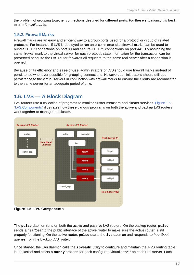
1.6. LVS — A Block DiagramLVS routers use a collection of programs to monitor cluster members and cluster services. Figure 1.5,“LVS Components” illustrates how these various programs on both the active and backup LVS routerswork together to manage the cluster.
Figure 1.5. LVS Components
The pulse daemon runs on both the active and passive LVS routers. On the backup router, pulsesends a heartbeat to the public interface of the active router to make sure the active router is stillproperly functioning. On the active router, pulse starts the lvs daemon and responds to heartbeatqueries from the backup LVS router.
Once started, the lvs daemon calls the ipvsadm utility to configure and maintain the IPVS routing tablein the kernel and starts a nanny process for each configured virtual server on each real server. Each
Chapter 1. Linux Virtual Server Overview
17
nanny process checks the state of one configured service on one real server, and tells the lvs daemonif the service on that real server is malfunctioning. If a malfunction is detected, the lvs daemon instructs ipvsadm to remove that real server from the IPVS routing table.
If the backup router does not receive a response from the active router, it initiates failover by calling send_arp to reassign all virtual IP addresses to the NIC hardware addresses (MAC address) of thebackup node, sends a command to the active router via both the public and private network interfaces toshut down the lvs daemon on the active router, and starts the lvs daemon on the backup node toaccept requests for the configured virtual servers.
1.6.1. LVS ComponentsSection 1.6.1.1, “pulse” shows a detailed list of each software component in an LVS router.
1.6.1.1. pulseThis is the controlling process which starts all other daemons related to LVS routers. At boot time, thedaemon is started by the /etc/rc.d/init.d/pulse script. It then reads the configuration file /etc/sysconfig/ha/lvs.cf. On the active router, pulse starts the LVS daemon. On the backuprouter, pulse determines the health of the active router by executing a simple heartbeat at a user-configurable interval. If the active router fails to respond after a user-configurable interval, it initiatesfailover. During failover, pulse on the backup router instructs the pulse daemon on the active router toshut down all LVS services, starts the send_arp program to reassign the floating IP addresses to thebackup router's MAC address, and starts the lvs daemon.
1.6.1.2. lvsThe lvs daemon runs on the active LVS router once called by pulse. It reads the configuration file /etc/sysconfig/ha/lvs.cf, calls the ipvsadm utility to build and maintain the IPVS routing table,and assigns a nanny process for each configured LVS service. If nanny reports a real server is down, lvs instructs the ipvsadm utility to remove the real server from the IPVS routing table.
1.6.1.3. ipvsadmThis service updates the IPVS routing table in the kernel. The lvs daemon sets up and administers LVSby calling ipvsadm to add, change, or delete entries in the IPVS routing table.
1.6.1.4 . nannyThe nanny monitoring daemon runs on the active LVS router. Through this daemon, the active routerdetermines the health of each real server and, optionally, monitors its workload. A separate processruns for each service defined on each real server.
1.6.1.5. /etc/sysconfig/ha/lvs.cfThis is the LVS configuration file. Directly or indirectly, all daemons get their configuration informationfrom this file.
1.6.1.6. Piranha Configuration ToolThis is the Web-based tool for monitoring, configuring, and administering LVS. This is the default tool tomaintain the /etc/sysconfig/ha/lvs.cf LVS configuration file.
1.6.1.7. send_arpThis program sends out ARP broadcasts when the floating IP address changes from one node toanother during failover.
Red Hat Enterprise Linux 4 Virtual Server Administration
18

Chapter 2, Initial LVS Configuration reviews important post-installation configuration steps you shouldtake before configuring Red Hat Enterprise Linux to be an LVS router.
Chapter 1. Linux Virtual Server Overview
19
Chapter 2. Initial LVS ConfigurationAfter installing Red Hat Enterprise Linux, you must take some basic steps to set up both the LVS routersand the real servers. This chapter covers these initial steps in detail.
Note
The LVS router node that becomes the active node once LVS is started is also referred to as theprimary node. When configuring LVS, use the Piranha Configuration Tool on the primary node.
2.1. Configuring Services on the LVS RoutersThe Red Hat Enterprise Linux installation program installs all of the components needed to set up LVS,but the appropriate services must be activated before configuring LVS. For both LVS routers, set theappropriate services to start at boot time. There are three primary tools available for setting services toactivate at boot time under Red Hat Enterprise Linux: the command line program chkconfig, thencurses-based program ntsysv, and the graphical Services Configuration Tool. All of these toolsrequire root access.
Note
To attain root access, open a shell prompt and use the su - command followed by the rootpassword. For example:
$ su - root password
On the LVS routers, there are three services which need to be set to activate at boot time:
The piranha-gui service (primary node only)
The pulse service
The sshd service
If you are clustering multi-port services or using firewall marks, you must also enable the iptablesservice.
It is best to set these services to activate in both runlevel 3 and runlevel 5. To accomplish this using chkconfig, type the following command for each service:
/sbin/chkconfig --level 35 daemon on
In the above command, replace daemon with the name of the service you are activating. To get a list ofservices on the system as well as what runlevel they are set to activate on, issue the followingcommand:
/sbin/chkconfig --list
Red Hat Enterprise Linux 4 Virtual Server Administration
20
Warning
Turning any of the above services on using chkconfig does not actually start the daemon. Todo this use the /sbin/service command. See Section 2.3, “Starting the PiranhaConfiguration Tool Service” for an example of how to use the /sbin/service command.
For more information on runlevels and configuring services with ntsysv and the ServicesConfiguration Tool, refer to the chapter titled "Controlling Access to Services" in the Red HatEnterprise Linux System Administration Guide.
2.2. Setting a Password for the Piranha Configuration ToolBefore using the Piranha Configuration Tool for the first time on the primary LVS router, you mustrestrict access to it by creating a password. To do this, login as root and issue the following command:
/usr/sbin/piranha-passwd
After entering this command, create the administrative password when prompted.
Warning
For a password to be more secure, it should not contain proper nouns, commonly used acronyms,or words in a dictionary from any language. Do not leave the password unencrypted anywhere onthe system.
If the password is changed during an active Piranha Configuration Tool session, the administrator isprompted to provide the new password.
2.3. Starting the Piranha Configuration Tool ServiceAfter you have set the password for the Piranha Configuration Tool, start or restart the piranha-gui service located in /etc/rc.d/init.d/piranha-gui. To do this, type the following command asroot:
/sbin/service piranha-gui start
or
/sbin/service piranha-gui restart
Issuing this command starts a private session of the Apache HTTP Server by calling the symbolic link /usr/sbin/piranha_gui -> /usr/sbin/httpd. For security reasons, the piranha-gui versionof httpd runs as the piranha user in a separate process. The fact that piranha-gui leverages the httpd service means that:
1. The Apache HTTP Server must be installed on the system.
2. Stopping or restarting the Apache HTTP Server via the service command stops the piranha-gui service.
Chapter 2. Initial LVS Configuration
21
Warning
If the command /sbin/service httpd stop or /sbin/service httpd restart is issuedon an LVS router, you must start the piranha-gui service by issuing the following command:/sbin/service piranha-gui start
The piranha-gui service is all that is necessary to begin configuring LVS. However, if you areconfiguring LVS remotely, the sshd service is also required. You do not need to start the pulse serviceuntil configuration using the Piranha Configuration Tool is complete. See Section 4.8, “Starting LVS”for information on starting the pulse service.
2.3.1. Configuring the Piranha Configuration Tool Web Server PortThe Piranha Configuration Tool runs on port 3636 by default. To change this port number, changethe line Listen 3636 in Section 2 of the piranha-gui Web server configuration file /etc/sysconfig/ha/conf/httpd.conf.
To use the Piranha Configuration Tool you need at minimum a text-only Web browser. If you start aWeb browser on the primary LVS router, open the location http://localhost:3636. You can reachthe Piranha Configuration Tool from anywhere via Web browser by replacing localhost with thehostname or IP address of the primary LVS router.
When your browser connects to the Piranha Configuration Tool, you must login to access theconfiguration services. Enter piranha in the Username field and the password set with piranha-passwd in the Password field.
Now that the Piranha Configuration Tool is running, you may wish to consider limiting who hasaccess to the tool over the network. The next section reviews ways to accomplish this task.
2.4. Limiting Access To the Piranha Configuration ToolThe Piranha Configuration Tool prompts for a valid username and password combination. However,because all of the data passed to the Piranha Configuration Tool is in plain text, it is recommendedthat you restrict access only to trusted networks or to the local machine.
The easiest way to restrict access is to use the Apache HTTP Server's built in access controlmechanisms by editing /etc/sysconfig/ha/web/secure/.htaccess. After altering the file you donot have to restart the piranha-gui service because the server checks the .htaccess file each timeit accesses the directory.
By default, the access controls for this directory allow anyone to view the contents of the directory. Hereis what the default access looks like:
Order deny,allowAllow from all
To limit access of the Piranha Configuration Tool to only the localhost change the .htaccess file toallow access from only the loopback device (127.0.0.1). For more information on the loopback device,see the chapter titled Network Scripts in the Red Hat Enterprise Linux Reference Guide.
Red Hat Enterprise Linux 4 Virtual Server Administration
22
Order deny,allowDeny from allAllow from 127.0.0.1
You can also allow specific hosts or subnets as seen in this example:
Order deny,allowDeny from allAllow from 192.168.1.100Allow from 172.16.57
In this example, only Web browsers from the machine with the IP address of 192.168.1.100 andmachines on the 172.16.57/24 network can access the Piranha Configuration Tool.
Warning
Editing the Piranha Configuration Tool.htaccess file limits access to the configurationpages in the /etc/sysconfig/ha/web/secure/ directory but not to the login and the helppages in /etc/sysconfig/ha/web/. To limit access to this directory, create a .htaccess filein the /etc/sysconfig/ha/web/ directory with order, allow, and deny lines identical to /etc/sysconfig/ha/web/secure/.htaccess.
2.5. Turning on Packet ForwardingIn order for the LVS router to forward network packets properly to the real servers, each LVS router nodemust have IP forwarding turned on in the kernel. Log in as root and change the line which reads net.ipv4.ip_forward = 0 in /etc/sysctl.conf to the following:
net.ipv4.ip_forward = 1
The changes take effect when you reboot the system.
To check if IP forwarding is turned on, issue the following command as root:
/sbin/sysctl net.ipv4.ip_forward
If the above command returns a 1, then IP forwarding is enabled. If it returns a 0, then you can turn it onmanually using the following command:
/sbin/sysctl -w net.ipv4.ip_forward=1
2.6. Configuring Services on the Real ServersIf the real servers are Red Hat Enterprise Linux systems, set the appropriate server daemons to activateat boot time. These daemons can include httpd for Web services or xinetd for FTP or Telnetservices.
It may also be useful to access the real servers remotely, so the sshd daemon should also be installedand running.
Chapter 2. Initial LVS Configuration
23
Chapter 3. Setting Up LVSLVS consists of two basic groups: the LVS routers and the real servers. To prevent a single point offailure, each groups should contain at least two member systems.
The LVS router group should consist of two identical or very similar systems running Red Hat EnterpriseLinux. One will act as the active LVS router while the other stays in hot standby mode, so they need tohave as close to the same capabilities as possible.
Before choosing and configuring the hardware for the real server group, determine which of the threeLVS topologies to use.
3.1. The NAT LVS NetworkThe NAT topology allows for great latitude in utilizing existing hardware, but it is limited in its ability tohandle large loads because all packets going into and coming out of the pool pass through the LVSrouter.
Network LayoutThe topology for LVS using NAT routing is the easiest to configure from a network layoutperspective because only one access point to the public network is needed. The real serverspass all requests back through the LVS router so they are on their own private network.
HardwareThe NAT topology is the most flexible in regards to hardware because the real servers do notneed to be Linux machines to function correctly. In a NAT topology, each real server only needsone NIC since it will only be responding to the LVS router. The LVS routers, on the other hand,need two NICs each to route traffic between the two networks. Because this topology creates anetwork bottleneck at the LVS router, gigabit Ethernet NICs can be employed on each LVSrouter to increase the bandwidth the LVS routers can handle. If gigabit Ethernet is employed onthe LVS routers, any switch connecting the real servers to the LVS routers must have at leasttwo gigabit Ethernet ports to handle the load efficiently.
SoftwareBecause the NAT topology requires the use of iptables for some configurations, there canbe a fair amount of software configuration outside of Piranha Configuration Tool. Inparticular, FTP services and the use of firewall marks requires extra manual configuration of theLVS routers to route requests properly.
3.1.1. Configuring Network Interfaces for LVS with NATTo set up LVS with NAT, you must first configure the network interfaces for the public network and theprivate network on the LVS routers. In this example, the LVS routers' public interfaces (eth0) will be onthe 192.168.26/24 network (I know, I know, this is not a routable IP, but let us pretend there is a firewall infront of the LVS router for good measure) and the private interfaces which link to the real servers (eth1)will be on the 10.11.12/24 network.
So on the active or primary LVS router node, the public interface's network script, /etc/sysconfig/network-scripts/ifcfg-eth0, could look something like this:
Red Hat Enterprise Linux 4 Virtual Server Administration
24
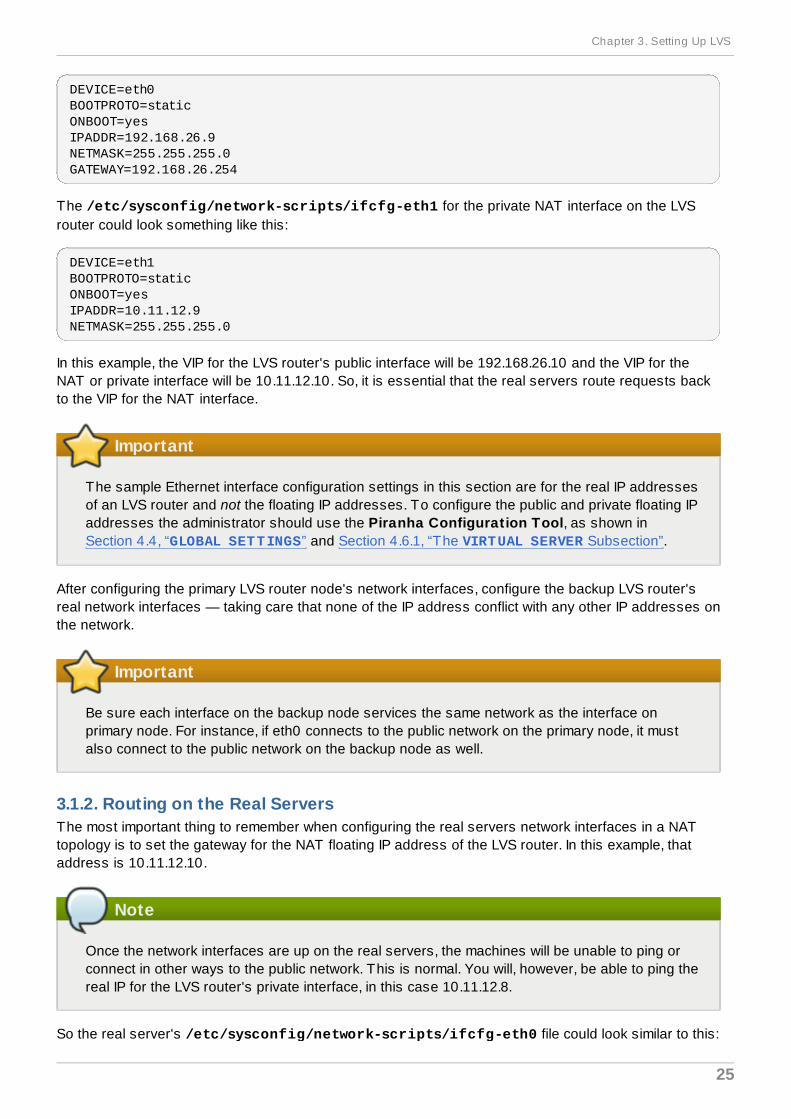
DEVICE=eth0BOOTPROTO=staticONBOOT=yesIPADDR=192.168.26.9NETMASK=255.255.255.0GATEWAY=192.168.26.254
The /etc/sysconfig/network-scripts/ifcfg-eth1 for the private NAT interface on the LVSrouter could look something like this:
DEVICE=eth1BOOTPROTO=staticONBOOT=yesIPADDR=10.11.12.9NETMASK=255.255.255.0
In this example, the VIP for the LVS router's public interface will be 192.168.26.10 and the VIP for theNAT or private interface will be 10.11.12.10. So, it is essential that the real servers route requests backto the VIP for the NAT interface.
Important
The sample Ethernet interface configuration settings in this section are for the real IP addressesof an LVS router and not the floating IP addresses. To configure the public and private floating IPaddresses the administrator should use the Piranha Configuration Tool, as shown inSection 4.4, “GLOBAL SETTINGS” and Section 4.6.1, “The VIRTUAL SERVER Subsection”.
After configuring the primary LVS router node's network interfaces, configure the backup LVS router'sreal network interfaces — taking care that none of the IP address conflict with any other IP addresses onthe network.
Important
Be sure each interface on the backup node services the same network as the interface onprimary node. For instance, if eth0 connects to the public network on the primary node, it mustalso connect to the public network on the backup node as well.
3.1.2. Routing on the Real ServersThe most important thing to remember when configuring the real servers network interfaces in a NATtopology is to set the gateway for the NAT floating IP address of the LVS router. In this example, thataddress is 10.11.12.10.
Note
Once the network interfaces are up on the real servers, the machines will be unable to ping orconnect in other ways to the public network. This is normal. You will, however, be able to ping thereal IP for the LVS router's private interface, in this case 10.11.12.8.
So the real server's /etc/sysconfig/network-scripts/ifcfg-eth0 file could look similar to this:
Chapter 3. Setting Up LVS
25
So the real server's /etc/sysconfig/network-scripts/ifcfg-eth0 file could look similar to this:
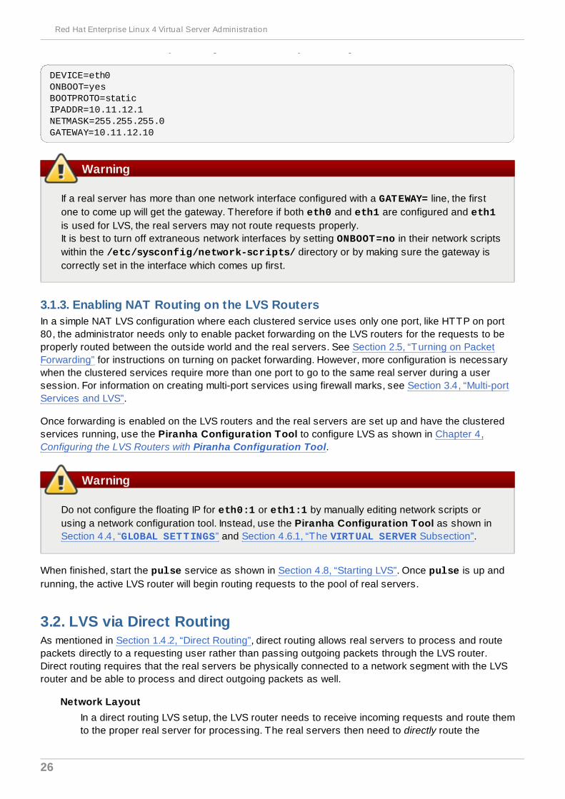
DEVICE=eth0ONBOOT=yesBOOTPROTO=staticIPADDR=10.11.12.1NETMASK=255.255.255.0GATEWAY=10.11.12.10
Warning
If a real server has more than one network interface configured with a GATEWAY= line, the firstone to come up will get the gateway. Therefore if both eth0 and eth1 are configured and eth1is used for LVS, the real servers may not route requests properly.It is best to turn off extraneous network interfaces by setting ONBOOT=no in their network scriptswithin the /etc/sysconfig/network-scripts/ directory or by making sure the gateway iscorrectly set in the interface which comes up first.
3.1.3. Enabling NAT Routing on the LVS RoutersIn a simple NAT LVS configuration where each clustered service uses only one port, like HTTP on port80, the administrator needs only to enable packet forwarding on the LVS routers for the requests to beproperly routed between the outside world and the real servers. See Section 2.5, “Turning on PacketForwarding” for instructions on turning on packet forwarding. However, more configuration is necessarywhen the clustered services require more than one port to go to the same real server during a usersession. For information on creating multi-port services using firewall marks, see Section 3.4, “Multi-portServices and LVS”.
Once forwarding is enabled on the LVS routers and the real servers are set up and have the clusteredservices running, use the Piranha Configuration Tool to configure LVS as shown in Chapter 4,Configuring the LVS Routers with Piranha Configuration Tool.
Warning
Do not configure the floating IP for eth0:1 or eth1:1 by manually editing network scripts orusing a network configuration tool. Instead, use the Piranha Configuration Tool as shown inSection 4.4, “GLOBAL SETTINGS” and Section 4.6.1, “The VIRTUAL SERVER Subsection”.
When finished, start the pulse service as shown in Section 4.8, “Starting LVS”. Once pulse is up andrunning, the active LVS router will begin routing requests to the pool of real servers.
3.2. LVS via Direct RoutingAs mentioned in Section 1.4.2, “Direct Routing”, direct routing allows real servers to process and routepackets directly to a requesting user rather than passing outgoing packets through the LVS router.Direct routing requires that the real servers be physically connected to a network segment with the LVSrouter and be able to process and direct outgoing packets as well.
Network LayoutIn a direct routing LVS setup, the LVS router needs to receive incoming requests and route themto the proper real server for processing. The real servers then need to directly route the
Red Hat Enterprise Linux 4 Virtual Server Administration
26
response to the client. So, for example, if the client is on the Internet, and sends the packetthrough the LVS router to a real server, the real server must be able to go directly to the clientvia the Internet. This can be done by configuring a gateway for the real server to pass packetsto the Internet. Each real server in the server pool can have its own separate gateway (andeach gateway with its own connection to the Internet), allowing for maximum throughput andscalability. For typical LVS setups, however, the real servers can communicate through onegateway (and therefore one network connection).
Important
It is not recommended to use the LVS router as a gateway for the real servers, as thatadds unneeded setup complexity as well as network load on the LVS router, whichreintroduces the network bottleneck that exists in NAT routing.
HardwareThe hardware requirements of an LVS system using direct routing is similar to other LVStopologies. While the LVS router needs to be running Red Hat Enterprise Linux to process theincoming requests and perform load-balancing for the real servers, the real servers do notneed to be Linux machines to function correctly. The LVS routers need one or two NICs each(depending on if there is a back-up router). You can use two NICs for ease of configuration andto distinctly separate traffic — incoming requests are handled by one NIC and routed packets toreal servers on the other.
Since the real servers bypass the LVS router and send outgoing packets directly to a client, agateway to the Internet is required. For maximum performance and availability, each real servercan be connected to its own separate gateway which has its own dedicated connection to thecarrier network to which the client is connected (such as the Internet or an intranet).
SoftwareThere is some configuration outside of Piranha Configuration Tool that needs to be done,especially for administrators facing ARP issues when using LVS via direct routing. Refer toSection 3.2.1, “Direct Routing and arptables_jf” or Section 3.2.2, “Direct Routing and iptables” for more information.
3.2.1. Direct Routing and arptables_jfIn order to configure direct routing using arptables_jf, each real server must have their virtual IPaddress configured, so they can directly route packets. ARP requests for the VIP are ignored entirely bythe real servers, and any ARP packets that might otherwise be sent containing the VIPs are mangled tocontain the real server's IP instead of the VIPs.
Using the arptables_jf method, applications may bind to each individual VIP or port that the realserver is servicing. For example, the arptables_jf method allows multiple instances of Apache HTTPServer to be running bound explicitly to different VIPs on the system. There are also significantperformance advantages to using arptables_jf over the iptables option.
However, using the arptables_jf method, VIPs can not be configured to start on boot using standardRed Hat Enterprise Linux system configuration tools.
To configure each real server to ignore ARP requests for each virtual IP addresses, perform the
Chapter 3. Setting Up LVS
27
To configure each real server to ignore ARP requests for each virtual IP addresses, perform thefollowing steps:
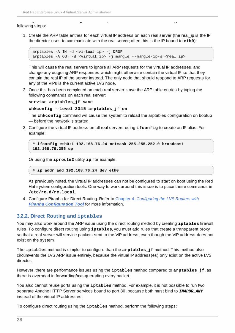
1. Create the ARP table entries for each virtual IP address on each real server (the real_ip is the IPthe director uses to communicate with the real server; often this is the IP bound to eth0):
arptables -A IN -d <virtual_ip> -j DROParptables -A OUT -d <virtual_ip> -j mangle --mangle-ip-s <real_ip>
This will cause the real servers to ignore all ARP requests for the virtual IP addresses, andchange any outgoing ARP responses which might otherwise contain the virtual IP so that theycontain the real IP of the server instead. The only node that should respond to ARP requests forany of the VIPs is the current active LVS node.
2. Once this has been completed on each real server, save the ARP table entries by typing thefollowing commands on each real server:
service arptables_jf save
chkconfig --level 2345 arptables_jf on
The chkconfig command will cause the system to reload the arptables configuration on bootup— before the network is started.
3. Configure the virtual IP address on all real servers using ifconfig to create an IP alias. Forexample:
# ifconfig eth0:1 192.168.76.24 netmask 255.255.252.0 broadcast 192.168.79.255 up
Or using the iproute2 utility ip, for example:
# ip addr add 192.168.76.24 dev eth0
As previously noted, the virtual IP addresses can not be configured to start on boot using the RedHat system configuration tools. One way to work around this issue is to place these commands in /etc/rc.d/rc.local.
4. Configure Piranha for Direct Routing. Refer to Chapter 4, Configuring the LVS Routers withPiranha Configuration Tool for more information.
3.2.2. Direct Routing and iptablesYou may also work around the ARP issue using the direct routing method by creating iptables firewallrules. To configure direct routing using iptables, you must add rules that create a transparent proxyso that a real server will service packets sent to the VIP address, even though the VIP address does notexist on the system.
The iptables method is simpler to configure than the arptables_jf method. This method alsocircumvents the LVS ARP issue entirely, because the virtual IP address(es) only exist on the active LVSdirector.
However, there are performance issues using the iptables method compared to arptables_jf, asthere is overhead in forwarding/masquerading every packet.
You also cannot reuse ports using the iptables method. For example, it is not possible to run twoseparate Apache HTTP Server services bound to port 80, because both must bind to INADDR_ANYinstead of the virtual IP addresses.
To configure direct routing using the iptables method, perform the following steps:
Red Hat Enterprise Linux 4 Virtual Server Administration
28
1. On each real server, run the following command for every VIP, port, and protocol (TCP or UDP)combination intended to be serviced for the real server:
iptables -t nat -A PREROUTING -p <tcp|udp> -d <vip> --dport <port> -j REDIRECT
This command will cause the real servers to process packets destined for the VIP and port thatthey are given.
2. Save the configuration on each real server:
# service iptables save# chkconfig --level 2345 iptables on
The commands above cause the system to reload the iptables configuration on bootup —before the network is started.
3.3. Putting the Configuration TogetherAfter determining which of the preceding routing methods to use, the hardware should be linked togetheron the network.
Important
The adapter devices on the LVS routers must be configured to access the same networks. Forinstance if eth0 connects to public network and eth1 connects to the private network, thenthese same devices on the backup LVS router must connect to the same networks.Also the gateway listed in the first interface to come up at boot time is added to the routing tableand subsequent gateways listed in other interfaces are ignored. This is especially important toconsider when configuring the real servers.
After physically connecting together the hardware, configure the network interfaces on the primary andbackup LVS routers. This can be done using a graphical application such as system-config-networkor by editing the network scripts manually. For more information about adding devices using system-config-network, see the chapter titled Network Configuration in the Red Hat Enterprise LinuxDeployment Guide. For the remainder of the chapter, example alterations to network interfaces are madeeither manually or through the Piranha Configuration Tool.
3.3.1. General LVS Networking TipsConfigure the real IP addresses for both the public and private networks on the LVS routers beforeattempting to configure LVS using the Piranha Configuration Tool. The sections on each topologygive example network addresses, but the actual network addresses are needed. Below are some usefulcommands for bringing up network interfaces or checking their status.
Bringing Up Real Network InterfacesTo bring up a real network interface, use the following command as root, replacing N with thenumber corresponding to the interface (eth0 and eth1).
/sbin/ifup ethN
Chapter 3. Setting Up LVS
29

Warning
Do not use the ifup scripts to bring up any floating IP addresses you may configureusing Piranha Configuration Tool (eth0:1 or eth1:1). Use the service commandto start pulse instead (see Section 4.8, “Starting LVS” for details).
Bringing Down Real Network InterfacesTo bring down a real network interface, use the following command as root, replacing N with thenumber corresponding to the interface (eth0 and eth1).
/sbin/ifdown ethN
Checking the Status of Network InterfacesIf you need to check which network interfaces are up at any given time, type the following:
/sbin/ifconfig
To view the routing table for a machine, issue the following command:
/sbin/route
3.4. Multi-port Services and LVSLVS routers under any topology require extra configuration when creating multi-port LVS services. Multi-port services can be created artificially by using firewall marks to bundle together different, but relatedprotocols, such as HTTP (port 80) and HTTPS (port 443), or when LVS is used with true multi-portprotocols, such as FTP. In either case, the LVS router uses firewall marks to recognize that packetsdestined for different ports, but bearing the same firewall mark, should be handled identically. Also, whencombined with persistence, firewall marks ensure connections from the client machine are routed to thesame host, as long as the connections occur within the length of time specified by the persistenceparameter. For more on assigning persistence to a virtual server, see Section 4.6.1, “The VIRTUALSERVER Subsection”.
Unfortunately, the mechanism used to balance the loads on the real servers — IPVS — can recognizethe firewall marks assigned to a packet, but cannot itself assign firewall marks. The job of assigningfirewall marks must be performed by the network packet filter, iptables, outside of PiranhaConfiguration Tool.
3.4.1. Assigning Firewall MarksTo assign firewall marks to a packet destined for a particular port, the administrator must use iptables.
This section illustrates how to bundle HTTP and HTTPS as an example; however, FTP is anothercommonly clustered multi-port protocol. If an LVS is used for FTP services, refer to Section 3.5,“Configuring FTP” for configuration details.
The basic rule to remember when using firewall marks is that for every protocol using a firewall mark inPiranha Configuration Tool there must be a commensurate iptables rule to assign marks to the
Red Hat Enterprise Linux 4 Virtual Server Administration
30
network packets.
Before creating network packet filter rules, make sure there are no rules already in place. To do this,open a shell prompt, login as root, and type:
/sbin/service iptables status
If iptables is not running, the prompt will instantly reappear.
If iptables is active, it displays a set of rules. If rules are present, type the following command:
/sbin/service iptables stop
If the rules already in place are important, check the contents of /etc/sysconfig/iptables andcopy any rules worth keeping to a safe place before proceeding.
Below are rules which assign the same firewall mark, 80, to incoming traffic destined for the floating IPaddress, n.n.n.n, on ports 80 and 443.
/sbin/modprobe ip_tables
/sbin/iptables -t mangle -A PREROUTING -p tcp -d n.n.n.n/32 --dport 80 -j MARK --set-mark 80
/sbin/iptables -t mangle-A PREROUTING -p tcp -d n.n.n.n/32 --dport 443 -j MARK --set-mark 80
For instructions on assigning the VIP to the public network interface, see Section 4.6.1, “The VIRTUALSERVER Subsection”. Also note that you must log in as root and load the module for iptables beforeissuing rules for the first time.
In the above iptables commands, n.n.n.n should be replaced with the floating IP for your HTTP andHTTPS virtual servers. These commands have the net effect of assigning any traffic addressed to theVIP on the appropriate ports a firewall mark of 80, which in turn is recognized by IPVS and forwardedappropriately.
Warning
The commands above will take effect immediately, but do not persist through a reboot of thesystem. To ensure network packet filter settings are restored upon reboot, refer to Section 3.6,“Saving Network Packet Filter Settings”
3.5. Configuring FTPFile Transport Protocol (FTP) is an old and complex multi-port protocol that presents a distinct set ofchallenges to an LVS environment. To understand the nature of these challenges, you must firstunderstand some key things about how FTP works.
3.5.1. How FTP WorksWith most other server client relationships, the client machine opens up a connection to the server on aparticular port and the server then responds to the client on that port. When an FTP client connects toan FTP server it opens a connection to the FTP control port 21. Then the client tells the FTP serverwhether to establish an active or passive connection. The type of connection chosen by the client
Chapter 3. Setting Up LVS
31
determines how the server responds and on what ports transactions will occur.
The two types of data connections are:
Active ConnectionsWhen an active connection is established, the server opens a data connection to the client fromport 20 to a high range port on the client machine. All data from the server is then passed overthis connection.
Passive ConnectionsWhen a passive connection is established, the client asks the FTP server to establish apassive connection port, which can be on any port higher than 10,000. The server then bindsto this high-numbered port for this particular session and relays that port number back to theclient. The client then opens the newly bound port for the data connection. Each data requestthe client makes results in a separate data connection. Most modern FTP clients attempt toestablish a passive connection when requesting data from servers.
Note
The client determines the type of connection, not the server. This means to effectively clusterFTP, you must configure the LVS routers to handle both active and passive connections.The FTP client/server relationship can potentially open a large number of ports that the PiranhaConfiguration Tool and IPVS do not know about.
3.5.2. How This Affects LVS RoutingIPVS packet forwarding only allows connections in and out of the cluster based on it recognizing its portnumber or its firewall mark. If a client from outside the cluster attempts to open a port IPVS is notconfigured to handle, it drops the connection. Similarly, if the real server attempts to open a connectionback out to the Internet on a port IPVS does not know about, it drops the connection. This means allconnections from FTP clients on the Internet must have the same firewall mark assigned to them and allconnections from the FTP server must be properly forwarded to the Internet using network packetfiltering rules.
3.5.3. Creating Network Packet Filter RulesBefore assigning any iptables rules for FTP service, review the information in Section 3.4.1,“Assigning Firewall Marks” concerning multi-port services and techniques for checking the existingnetwork packet filtering rules.
Below are rules which assign the same firewall mark, 21, to FTP traffic. For these rules to work properly,you must also use the VIRTUAL SERVER subsection of Piranha Configuration Tool to configure avirtual server for port 21 with a value of 21 in the Firewall Mark field. See Section 4.6.1, “TheVIRTUAL SERVER Subsection” for details.
3.5.3.1. Rules for Active ConnectionsThe rules for active connections tell the kernel to accept and forward connections coming to the internalfloating IP address on port 20 — the FTP data port.
The following iptables command allows the LVS router to accept outgoing connections from the real
Red Hat Enterprise Linux 4 Virtual Server Administration
32
servers that IPVS does not know about:
/sbin/iptables -t nat -A POSTROUTING -p tcp -s n.n.n.0/24 --sport 20 -j MASQUERADE
In the iptables command, n.n.n should be replaced with the first three values for the floating IP forthe NAT interface's internal network interface defined in the GLOBAL SETTINGS panel of PiranhaConfiguration Tool.
3.5.3.2. Rules for Passive ConnectionsThe rules for passive connections assign the appropriate firewall mark to connections coming in fromthe Internet to the floating IP for the service on a wide range of ports — 10,000 to 20,000.
Warning
If you are limiting the port range for passive connections, you must also configure the VSFTPserver to use a matching port range. This can be accomplished by adding the following lines to /etc/vsftpd.conf:pasv_min_port=10000pasv_max_port=20000You must also control the address that the server displays to the client for passive FTPconnections. In a NAT routed LVS system, add the following line to /etc/vsftpd.conf tooverride the real server IP address to the VIP, which is what the client sees upon connection. Forexample:pasv_address=n.n.n.nReplace n.n.n.n with the VIP address of the LVS system.For configuration of other FTP servers, consult the respective documentation.
This range should be a wide enough for most situations; however, you can increase this number toinclude all available non-secured ports by changing 10000:20000 in the commands below to 1024:65535.
The following iptables commands have the net effect of assigning any traffic addressed to thefloating IP on the appropriate ports a firewall mark of 21, which is in turn recognized by IPVS andforwarded appropriately:
/sbin/iptables -t mangle -A PREROUTING -p tcp -d n.n.n.n/32 --dport 21 -j MARK --set-mark 21
/sbin/iptables -t mangle -A PREROUTING -p tcp -d n.n.n.n/32 --dport 10000:20000 -j MARK --set-mark 21
In the iptables commands, n.n.n.n should be replaced with the floating IP for the FTP virtual serverdefined in the VIRTUAL SERVER subsection of Piranha Configuration Tool.
Warning
The commands above take effect immediately, but do not persist through a reboot of the system.To ensure network packet filter settings are restored after a reboot, see Section 3.6, “SavingNetwork Packet Filter Settings”
Chapter 3. Setting Up LVS
33

Finally, you need to be sure that the appropriate service is set to activate on the proper runlevels. Formore on this, refer to Section 2.1, “Configuring Services on the LVS Routers”.
3.6. Saving Network Packet Filter SettingsAfter configuring the appropriate network packet filters for your situation, save the settings so they getrestored after a reboot. For iptables, type the following command:
/sbin/service iptables save
This saves the settings in /etc/sysconfig/iptables so they can be recalled at boot time.
Once this file is written, you are able to use the /sbin/service command to start, stop, and check thestatus (using the status switch) of iptables. The /sbin/service will automatically load theappropriate module for you. For an example of how to use the /sbin/service command, seeSection 2.3, “Starting the Piranha Configuration Tool Service”.
Finally, you need to be sure the appropriate service is set to activate on the proper runlevels. For moreon this, see Section 2.1, “Configuring Services on the LVS Routers”.
The next chapter explains how to use the Piranha Configuration Tool to configure the LVS routerand describe the steps necessary to activate LVS.
Red Hat Enterprise Linux 4 Virtual Server Administration
34
Chapter 4. Configuring the LVS Routers with PiranhaConfiguration ToolThe Piranha Configuration Tool provides a structured approach to creating the necessaryconfiguration file for LVS — /etc/sysconfig/ha/lvs.cf. This chapter describes the basic operationof the Piranha Configuration Tool and how to activate LVS once configuration is complete.
Important
The configuration file for LVS follows strict formatting rules. Using the Piranha ConfigurationTool is the best way to prevent syntax errors in the lvs.cf and therefore prevent softwarefailures.
4.1. Necessary SoftwareThe piranha-gui service must be running on the primary LVS router to use the PiranhaConfiguration Tool. To configure LVS, you minimally need a text-only Web browser, such as links. Ifyou are accessing the LVS router from another machine, you also need an ssh connection to the primaryLVS router as the root user.
While configuring the primary LVS router it is a good idea to keep a concurrent ssh connection in aterminal window. This connection provides a secure way to restart pulse and other services, configurenetwork packet filters, and monitor /var/log/messages during trouble shooting.
The next four sections walk through each of the configuration pages of the Piranha ConfigurationTool and give instructions on using it to set up LVS.
4.2. Logging Into the Piranha Configuration ToolWhen configuring LVS, you should always begin by configuring the primary router with the PiranhaConfiguration Tool. To do this,verify that the piranha-gui service is running and an administrativepassword has been set, as described in Section 2.2, “Setting a Password for the PiranhaConfiguration Tool”.
If you are accessing the machine locally, you can open http://localhost:3636 in a Web browser toaccess the Piranha Configuration Tool. Otherwise, type in the hostname or real IP address for theserver followed by :3636. Once the browser connects, you will see the screen shown in Figure 4.1,“The Welcome Panel”.
Chapter 4. Configuring the LVS Routers with Piranha Configuration Tool
35
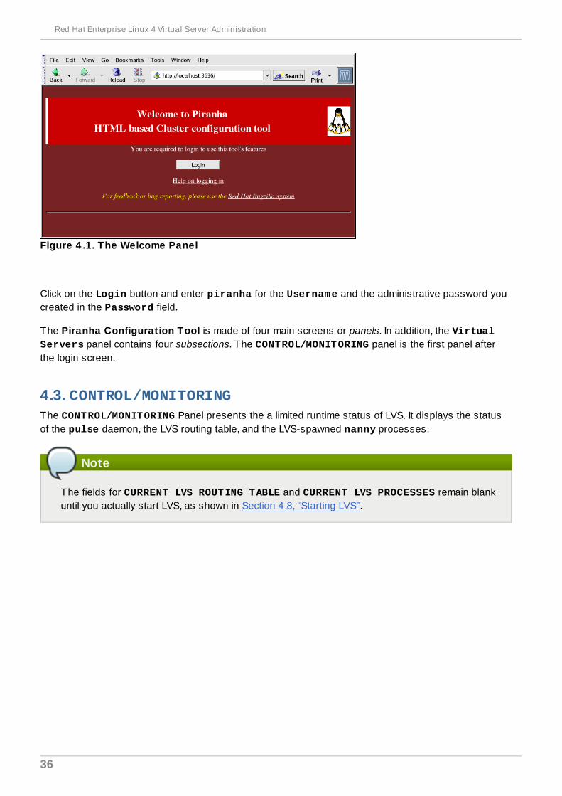
Figure 4 .1. The Welcome Panel
Click on the Login button and enter piranha for the Username and the administrative password youcreated in the Password field.
The Piranha Configuration Tool is made of four main screens or panels. In addition, the VirtualServers panel contains four subsections. The CONTROL/MONITORING panel is the first panel afterthe login screen.
4.3. CONTROL/MONITORINGThe CONTROL/MONITORING Panel presents the a limited runtime status of LVS. It displays the statusof the pulse daemon, the LVS routing table, and the LVS-spawned nanny processes.
Note
The fields for CURRENT LVS ROUTING TABLE and CURRENT LVS PROCESSES remain blankuntil you actually start LVS, as shown in Section 4.8, “Starting LVS”.
Red Hat Enterprise Linux 4 Virtual Server Administration
36

Figure 4 .2. The CONTROL/MONITORING Panel
Auto update
The status display on this page can be updated automatically at a user configurable interval.To enable this feature, click on the Auto update checkbox and set the desired updatefrequency in the Update frequency in seconds text box (the default value is 10seconds).
It is not recommended that you set the automatic update to an interval less than 10 seconds.Doing so may make it difficult to reconfigure the Auto update interval because the page willupdate too frequently. If you encounter this issue, simply click on another panel and then backon CONTROL/MONITORING.
The Auto update feature does not work with all browsers, such as Mozilla .
Update information now
You can manually update the status information manually by clicking this button.
CHANGE PASSWORD
Clicking this button takes you to a help screen with information on how to change theadministrative password for the Piranha Configuration Tool.
4.4. GLOBAL SETTINGSThe GLOBAL SETTINGS panel is where the you define the networking details for the primary LVSrouter's public and private network interfaces.
Chapter 4. Configuring the LVS Routers with Piranha Configuration Tool
37
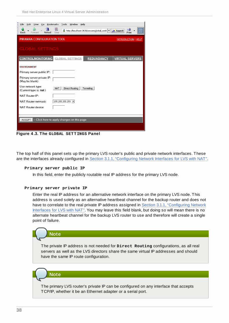
Figure 4 .3. The GLOBAL SETTINGS Panel
The top half of this panel sets up the primary LVS router's public and private network interfaces. Theseare the interfaces already configured in Section 3.1.1, “Configuring Network Interfaces for LVS with NAT”.
Primary server public IP
In this field, enter the publicly routable real IP address for the primary LVS node.
Primary server private IP
Enter the real IP address for an alternative network interface on the primary LVS node. Thisaddress is used solely as an alternative heartbeat channel for the backup router and does nothave to correlate to the real private IP address assigned in Section 3.1.1, “Configuring NetworkInterfaces for LVS with NAT”. You may leave this field blank, but doing so will mean there is noalternate heartbeat channel for the backup LVS router to use and therefore will create a singlepoint of failure.
Note
The private IP address is not needed for Direct Routing configurations, as all realservers as well as the LVS directors share the same virtual IP addresses and shouldhave the same IP route configuration.
Note
The primary LVS router's private IP can be configured on any interface that acceptsTCP/IP, whether it be an Ethernet adapter or a serial port.
Red Hat Enterprise Linux 4 Virtual Server Administration
38
Use network type
Click the NAT button to select NAT routing.
Click the Direct Routing button to select direct routing.
The next three fields deal specifically with the NAT router's virtual network interface connecting theprivate network with the real servers. These fields do not apply to the direct routing network type.
NAT Router IP
Enter the private floating IP in this text field. This floating IP should be used as the gateway forthe real servers.
NAT Router netmask
If the NAT router's floating IP needs a particular netmask, select it from drop-down list.
NAT Router device
Use this text field to define the device name of the network interface for the floating IP address,such as eth1:1.
Note
You should alias the NAT floating IP address to the Ethernet interface connected to theprivate network. In this example, the private network is on the eth1 interface, so eth1:1is the floating IP address.
Warning
After completing this page, click the ACCEPT button to make sure you do not lose any changeswhen selecting a new panel.
4.5. REDUNDANCYThe REDUNDANCY panel allows you to configure of the backup LVS router node and set variousheartbeat monitoring options.
Note
The first time you visit this screen, it displays an "inactive" Backup status and an ENABLEbutton. To configure the backup LVS router, click on the ENABLE button so that the screenmatches Figure 4.4, “The REDUNDANCY Panel”.
Chapter 4. Configuring the LVS Routers with Piranha Configuration Tool
39
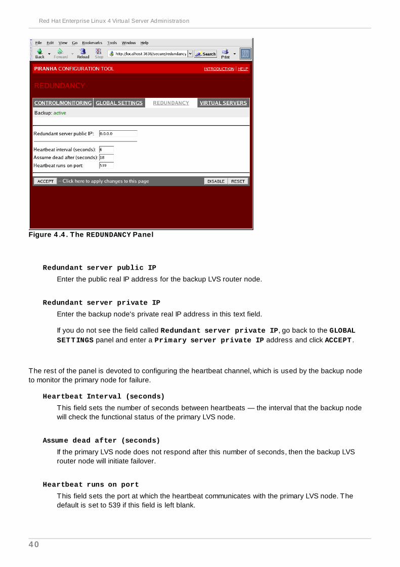
Figure 4 .4 . The REDUNDANCY Panel
Redundant server public IP
Enter the public real IP address for the backup LVS router node.
Redundant server private IP
Enter the backup node's private real IP address in this text field.
If you do not see the field called Redundant server private IP, go back to the GLOBALSETTINGS panel and enter a Primary server private IP address and click ACCEPT .
The rest of the panel is devoted to configuring the heartbeat channel, which is used by the backup nodeto monitor the primary node for failure.
Heartbeat Interval (seconds)
This field sets the number of seconds between heartbeats — the interval that the backup nodewill check the functional status of the primary LVS node.
Assume dead after (seconds)
If the primary LVS node does not respond after this number of seconds, then the backup LVSrouter node will initiate failover.
Heartbeat runs on port
This field sets the port at which the heartbeat communicates with the primary LVS node. Thedefault is set to 539 if this field is left blank.
Red Hat Enterprise Linux 4 Virtual Server Administration
40
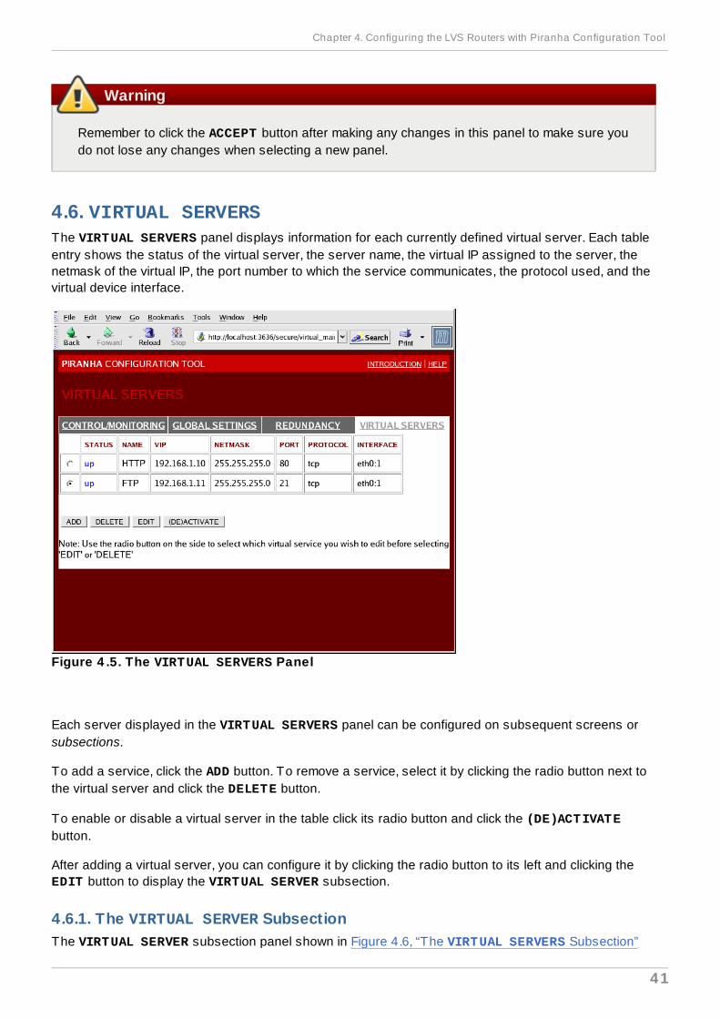
Warning
Remember to click the ACCEPT button after making any changes in this panel to make sure youdo not lose any changes when selecting a new panel.
4.6. VIRTUAL SERVERSThe VIRTUAL SERVERS panel displays information for each currently defined virtual server. Each tableentry shows the status of the virtual server, the server name, the virtual IP assigned to the server, thenetmask of the virtual IP, the port number to which the service communicates, the protocol used, and thevirtual device interface.
Figure 4 .5. The VIRTUAL SERVERS Panel
Each server displayed in the VIRTUAL SERVERS panel can be configured on subsequent screens orsubsections.
To add a service, click the ADD button. To remove a service, select it by clicking the radio button next tothe virtual server and click the DELETE button.
To enable or disable a virtual server in the table click its radio button and click the (DE)ACTIVATEbutton.
After adding a virtual server, you can configure it by clicking the radio button to its left and clicking theEDIT button to display the VIRTUAL SERVER subsection.
4.6.1. The VIRTUAL SERVER SubsectionThe VIRTUAL SERVER subsection panel shown in Figure 4.6, “The VIRTUAL SERVERS Subsection”
Chapter 4. Configuring the LVS Routers with Piranha Configuration Tool
41
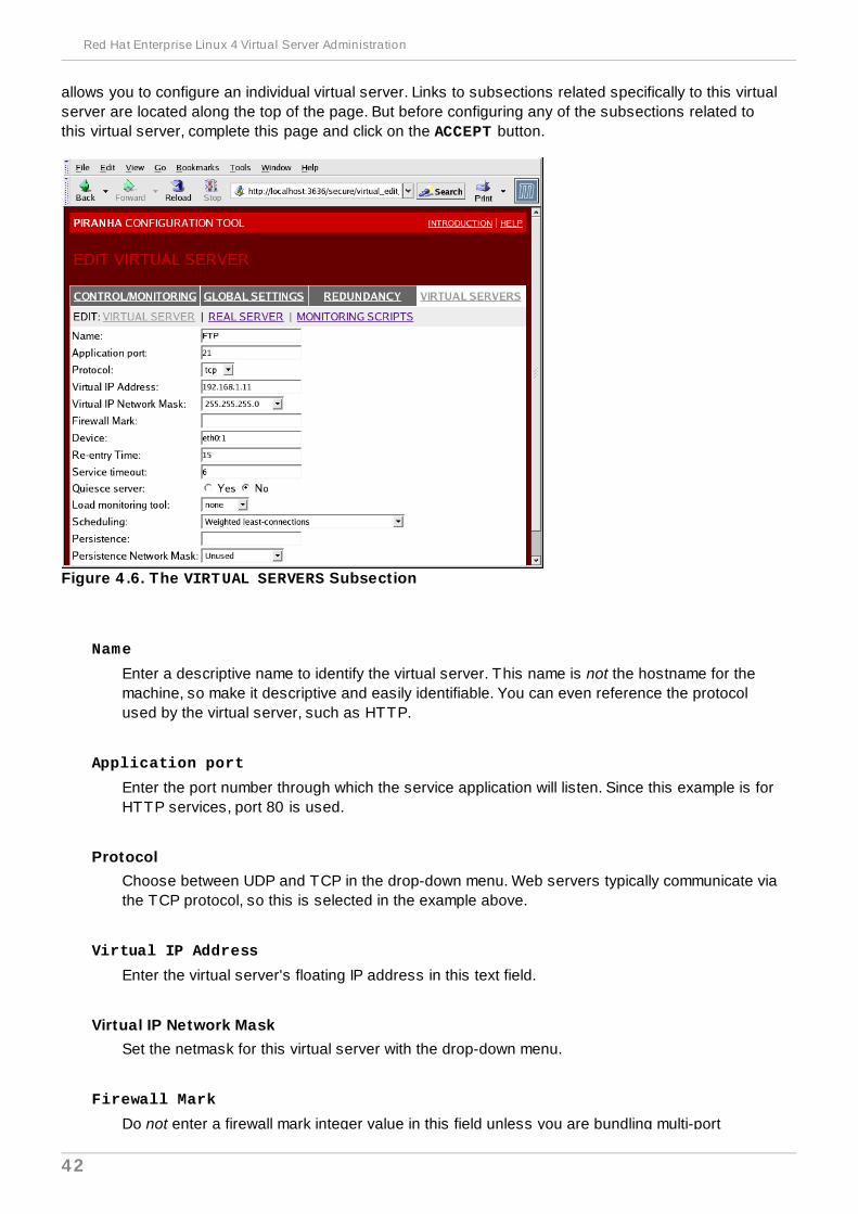
allows you to configure an individual virtual server. Links to subsections related specifically to this virtualserver are located along the top of the page. But before configuring any of the subsections related tothis virtual server, complete this page and click on the ACCEPT button.
Figure 4 .6. The VIRTUAL SERVERS Subsection
Name
Enter a descriptive name to identify the virtual server. This name is not the hostname for themachine, so make it descriptive and easily identifiable. You can even reference the protocolused by the virtual server, such as HTTP.
Application port
Enter the port number through which the service application will listen. Since this example is forHTTP services, port 80 is used.
ProtocolChoose between UDP and TCP in the drop-down menu. Web servers typically communicate viathe TCP protocol, so this is selected in the example above.
Virtual IP Address
Enter the virtual server's floating IP address in this text field.
Virtual IP Network MaskSet the netmask for this virtual server with the drop-down menu.
Firewall Mark
Do not enter a firewall mark integer value in this field unless you are bundling multi-port
Red Hat Enterprise Linux 4 Virtual Server Administration
42
protocols or creating a multi-port virtual server for separate, but related protocols. In thisexample, the above virtual server has a Firewall Mark of 80 because we are bundlingconnections to HTTP on port 80 and to HTTPS on port 443 using the firewall mark value of 80.When combined with persistence, this technique will ensure users accessing both insecure andsecure webpages are routed to the same real server, preserving state.
Warning
Entering a firewall mark in this field allows IPVS to recognize that packets bearing thisfirewall mark are treated the same, but you must perform further configuration outside ofthe Piranha Configuration Tool to actually assign the firewall marks. See Section 3.4,“Multi-port Services and LVS” for instructions on creating multi-port services andSection 3.5, “Configuring FTP” for creating a highly available FTP virtual server.
Device
Enter the name of the network device to which you want the floating IP address defined theVirtual IP Address field to bind.
You should alias the public floating IP address to the Ethernet interface connected to the publicnetwork. In this example, the public network is on the eth0 interface, so eth0:1 should beentered as the device name.
Re-entry Time
Enter an integer value which defines the length of time, in seconds, before the active LVS routerattempts to bring a real server back into the pool after a failure.
Service Timeout
Enter an integer value which defines the length of time, in seconds, before a real server isconsidered dead and removed from the pool.
Quiesce server
When the Quiesce server radio button is selected, anytime a new real server node comesonline, the least-connections table is reset to zero so the active LVS router routes requests asif all the real servers were freshly added to the pool. This option prevents the a new serverfrom becoming bogged down with a high number of connections upon entering the pool.
Load monitoring tool
The LVS router can monitor the load on the various real servers by using either rup or ruptime. If you select rup from the drop-down menu, each real server must run the rstatdservice. If you select ruptime, each real server must run the rwhod service.
Chapter 4. Configuring the LVS Routers with Piranha Configuration Tool
43

Warning
Load monitoring is not the same as load balancing and can result in hard to predictscheduling behavior when combined with weighted scheduling algorithms. Also, if youuse load monitoring, the real servers must be Linux machines.
Scheduling
Select your preferred scheduling algorithm from the drop-down menu. The default is Weighted least-connection. For more information on scheduling algorithms, see Section 1.3.1,“Scheduling Algorithms”.
Persistence
If an administrator needs persistent connections to the virtual server during client transactions,enter the number of seconds of inactivity allowed to lapse before a connection times out in thistext field.
Important
If you entered a value in the Firewall Mark field above, you should enter a value forpersistence as well. Also, be sure that if you use firewall marks and persistencetogether, that the amount of persistence is the same for each virtual server with thefirewall mark. For more on persistence and firewall marks, refer to Section 1.5,“Persistence and Firewall Marks”.
Persistence Network MaskTo limit persistence to particular subnet, select the appropriate network mask from the drop-down menu.
Note
Before the advent of firewall marks, persistence limited by subnet was a crude way ofbundling connections. Now, it is best to use persistence in relation to firewall marks toachieve the same result.
Warning
Remember to click the ACCEPT button after making any changes in this panel. To make sure youdo not lose changes when selecting a new panel.
4.6.2. REAL SERVER SubsectionClicking on the REAL SERVER subsection link at the top of the panel displays the EDIT REAL SERVER
Red Hat Enterprise Linux 4 Virtual Server Administration
44
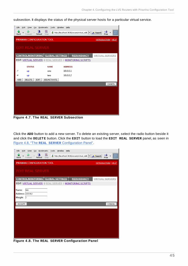
subsection. It displays the status of the physical server hosts for a particular virtual service.
Figure 4 .7. The REAL SERVER Subsection
Click the ADD button to add a new server. To delete an existing server, select the radio button beside itand click the DELETE button. Click the EDIT button to load the EDIT REAL SERVER panel, as seen inFigure 4.8, “The REAL SERVER Configuration Panel”.
Figure 4 .8. The REAL SERVER Configuration Panel
Chapter 4. Configuring the LVS Routers with Piranha Configuration Tool
45

This panel consists of three entry fields:
Name
A descriptive name for the real server.
Note
This name is not the hostname for the machine, so make it descriptive and easilyidentifiable.
Address
The real server's IP address. Since the listening port is already specified for the associatedvirtual server, do not add a port number.
Weight
An integer value indicating this host's capacity relative to that of other hosts in the pool. Thevalue can be arbitrary, but treat it as a ratio in relation to other real servers in the pool. For moreon server weight, see Section 1.3.2, “Server Weight and Scheduling”.
Warning
Remember to click the ACCEPT button after making any changes in this panel. To make sure youdo not lose any changes when selecting a new panel.
4.6.3. EDIT MONITORING SCRIPTS SubsectionClick on the MONITORING SCRIPTS link at the top of the page. The EDIT MONITORING SCRIPTSsubsection allows the administrator to specify a send/expect string sequence to verify that the servicefor the virtual server is functional on each real server. It is also the place where the administrator canspecify customized scripts to check services requiring dynamically changing data.
Red Hat Enterprise Linux 4 Virtual Server Administration
46

Figure 4 .9. The EDIT MONITORING SCRIPTS Subsection
Sending Program
For more advanced service verification, you can use this field to specify the path to a service-checking script. This functionality is especially helpful for services that require dynamicallychanging data, such as HTTPS or SSL.
To use this functionality, you must write a script that returns a textual response, set it to beexecutable, and type the path to it in the Sending Program field.
Note
To ensure that each server in the real server pool is checked, use the special token %hafter the path to the script in the Sending Program field. This token is replaced witheach real server's IP address as the script is called by the nanny daemon.
The following is a sample script to use as a guide when composing an external service-checking script:
#!/bin/sh
TEST=`dig -t soa example.com @$1 | grep -c dns.example.com
if [ $TEST != "1" ]; then echo "OKelse echo "FAIL"fi
Chapter 4. Configuring the LVS Routers with Piranha Configuration Tool
47
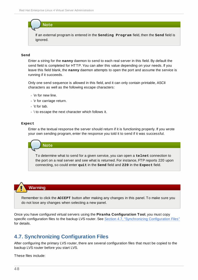
Note
If an external program is entered in the Sending Program field, then the Send field isignored.
Send
Enter a string for the nanny daemon to send to each real server in this field. By default thesend field is completed for HTTP. You can alter this value depending on your needs. If youleave this field blank, the nanny daemon attempts to open the port and assume the service isrunning if it succeeds.
Only one send sequence is allowed in this field, and it can only contain printable, ASCIIcharacters as well as the following escape characters:
\n for new line.
\r for carriage return.
\t for tab.
\ to escape the next character which follows it.
Expect
Enter a the textual response the server should return if it is functioning properly. If you wroteyour own sending program, enter the response you told it to send if it was successful.
Note
To determine what to send for a given service, you can open a telnet connection tothe port on a real server and see what is returned. For instance, FTP reports 220 uponconnecting, so could enter quit in the Send field and 220 in the Expect field.
Warning
Remember to click the ACCEPT button after making any changes in this panel. To make sure youdo not lose any changes when selecting a new panel.
Once you have configured virtual servers using the Piranha Configuration Tool, you must copyspecific configuration files to the backup LVS router. See Section 4.7, “Synchronizing Configuration Files”for details.
4.7. Synchronizing Configuration FilesAfter configuring the primary LVS router, there are several configuration files that must be copied to thebackup LVS router before you start LVS.
These files include:
Red Hat Enterprise Linux 4 Virtual Server Administration
48
/etc/sysconfig/ha/lvs.cf — the configuration file for the LVS routers.
/etc/sysctl — the configuration file that, among other things, turns on packet forwarding in thekernel.
/etc/sysconfig/iptables — If you are using firewall marks, you should synchronize one ofthese files based on which network packet filter you are using.
Important
The /etc/sysctl.conf and /etc/sysconfig/iptables files do not change when youconfigure LVS using the Piranha Configuration Tool.
4.7.1. Synchronizing lvs.cfAnytime the LVS configuration file, /etc/sysconfig/ha/lvs.cf, is created or updated, you mustcopy it to the backup LVS router node.
Warning
Both the active and backup LVS router nodes must have identical lvs.cf files. Mismatched LVSconfiguration files between the LVS router nodes can prevent failover.
The best way to do this is to use the scp command.
Important
To use scp the sshd must be running on the backup router, see Section 2.1, “ConfiguringServices on the LVS Routers” for details on how to properly configure the necessary services onthe LVS routers.
Issue the following command as the root user from the primary LVS router to sync the lvs.cf filesbetween the router nodes:
scp /etc/sysconfig/ha/lvs.cf n.n.n.n:/etc/sysconfig/ha/lvs.cf
In the command, replace n.n.n.n with the real IP address of the backup LVS router.
4.7.2. Synchronizing sysctlThe sysctl file is only modified once in most situations. This file is read at boot time and tells the kernelto turn on packet forwarding.
Important
If you are not sure whether or not packet forwarding is enabled in the kernel, see Section 2.5,“Turning on Packet Forwarding” for instructions on how to check and, if necessary, enable thiskey functionality.
Chapter 4. Configuring the LVS Routers with Piranha Configuration Tool
49
4.7.3. Synchronizing Network Packet Filtering RulesIf you are using iptables, you will need to synchronize the appropriate configuration file on the backupLVS router.
If you alter the any network packet filter rules, enter the following command as root from the primary LVSrouter:
scp /etc/sysconfig/iptables n.n.n.n:/etc/sysconfig/
In the command, replace n.n.n.n with the real IP address of the backup LVS router.
Next either open an ssh session to the backup router or log into the machine as root and type thefollowing command:
/sbin/service iptables restart
Once you have copied these files over to the backup router and started the appropriate services (seeSection 2.1, “Configuring Services on the LVS Routers” for more on this topic) you are ready to start LVS.
4.8. Starting LVSTo start LVS, it is best to have two root terminals open simultaneously or two simultaneous root open ssh sessions to the primary LVS router.
In one terminal, watch the kernel log messages with the command:
tail -f /var/log/messages
Then start LVS by typing the following command into the other terminal:
/sbin/service pulse start
Follow the progress of the pulse service's startup in the terminal with the kernel log messages. Whenyou see the following output, the pulse daemon has started properly:
gratuitous lvs arps finished
To stop watching /var/log/messages, type Ctrl+c.
From this point on, the primary LVS router is also the active LVS router. While you can make requests toLVS at this point, you should start the backup LVS router before putting LVS into service. To do this,simply repeat the process described above on the backup LVS router node.
After completing this final step, LVS will be up and running.
Red Hat Enterprise Linux 4 Virtual Server Administration
50
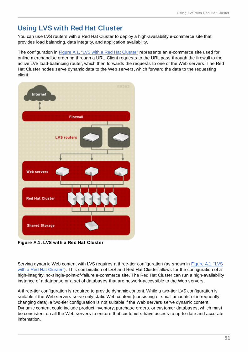
Using LVS with Red Hat ClusterYou can use LVS routers with a Red Hat Cluster to deploy a high-availability e-commerce site thatprovides load balancing, data integrity, and application availability.
The configuration in Figure A.1, “LVS with a Red Hat Cluster” represents an e-commerce site used foronline merchandise ordering through a URL. Client requests to the URL pass through the firewall to theactive LVS load-balancing router, which then forwards the requests to one of the Web servers. The RedHat Cluster nodes serve dynamic data to the Web servers, which forward the data to the requestingclient.
Figure A.1. LVS with a Red Hat Cluster
Serving dynamic Web content with LVS requires a three-tier configuration (as shown in Figure A.1, “LVSwith a Red Hat Cluster”). This combination of LVS and Red Hat Cluster allows for the configuration of ahigh-integrity, no-single-point-of-failure e-commerce site. The Red Hat Cluster can run a high-availabilityinstance of a database or a set of databases that are network-accessible to the Web servers.
A three-tier configuration is required to provide dynamic content. While a two-tier LVS configuration issuitable if the Web servers serve only static Web content (consisting of small amounts of infrequentlychanging data), a two-tier configuration is not suitable if the Web servers serve dynamic content.Dynamic content could include product inventory, purchase orders, or customer databases, which mustbe consistent on all the Web servers to ensure that customers have access to up-to-date and accurateinformation.
Using LVS with Red Hat Cluster
51
Each tier provides the following functions:
First tier — LVS routers performing load-balancing to distribute Web requests.
Second tier — A set of Web servers to serve the requests.
Third tier — A Red Hat Cluster to serve data to the Web servers.
In an LVS configuration like the one in Figure A.1, “LVS with a Red Hat Cluster”, client systems issuerequests on the World Wide Web. For security reasons, these requests enter a Web site through afirewall, which can be a Linux system serving in that capacity or a dedicated firewall device. Forredundancy, you can configure firewall devices in a failover configuration. Behind the firewall are LVSload-balancing routers, which can be configured in an active-standby mode. The active load-balancingrouter forwards the requests to the set of Web servers.
Each Web server can independently process an HTTP request from a client and send the responseback to the client. LVS enables you to expand a Web site's capacity by adding Web servers behind theLVS routers; the LVS routers perform load balancing across a wider set of Web servers. In addition, if aWeb server fails, it can be removed; LVS continues to perform load balancing across a smaller set ofWeb servers.
Red Hat Enterprise Linux 4 Virtual Server Administration
52
Revision HistoryRevision 1.0-5.4 00 2013-10-31 Rüdiger Landmann
Rebuild with publican 4.0.0
Revision 1.0-5 2012-07-18 Anthony TownsRebuild for Publican 3.0
Revision 1.0-0 Fri Apr 24 2009
IndexSymbols
/etc/sysconfig/ha/lvs.cf file, /etc/sysconfig/ha/lvs.cf
Aarptables_jf, Direct Routing and arptables_jf
Cchkconfig, Configuring Services on the LVS Routers
cluster- using LVS with Red Hat Cluster, Using LVS with Red Hat Cluster
components- of LVS, LVS Components
Ddirect routing
- and arptables_jf, Direct Routing and arptables_jf
Ffeedback, Feedback
FTP, Configuring FTP- (see also LVS)
Iintroduction, Introduction
- other Red Hat Enterprise Linux documents, Introduction
iptables, Configuring Services on the LVS Routers
Revision History
53
ipvsadm program, ipvsadm
Jjob scheduling, LVS, LVS Scheduling Overview
Lleast connections (see job scheduling, LVS)
LVS- /etc/sysconfig/ha/lvs.cf file, /etc/sysconfig/ha/lvs.cf- components of, LVS Components- daemon, lvs- date replication, real servers, Data Replication and Data Sharing Between Real Servers- direct routing
- and arptables_jf, Direct Routing and arptables_jf- requirements, hardware, Direct Routing, LVS via Direct Routing- requirements, network, Direct Routing, LVS via Direct Routing- requirements, software, Direct Routing, LVS via Direct Routing
- initial configuration, Initial LVS Configuration- ipvsadm program, ipvsadm- job scheduling, LVS Scheduling Overview- lvs daemon, lvs- LVS routers
- configuring services, Initial LVS Configuration- necessary services, Configuring Services on the LVS Routers- primary node, Initial LVS Configuration
- multi-port services, Multi-port Services and LVS- FTP, Configuring FTP
- nanny daemon, nanny- NAT routing
- enabling, Enabling NAT Routing on the LVS Routers- requirements, hardware, The NAT LVS Network- requirements, network, The NAT LVS Network- requirements, software, The NAT LVS Network
- overview of, Linux Virtual Server Overview- packet forwarding, Turning on Packet Forwarding- Piranha Configuration Tool, Piranha Configuration Tool- pulse daemon, pulse- real servers, Linux Virtual Server Overview- routing methods
- NAT, Routing Methods
- routing prerequisites, Configuring Network Interfaces for LVS with NAT- scheduling, job, LVS Scheduling Overview- send_arp program, send_arp- shared data, Data Replication and Data Sharing Between Real Servers
Red Hat Enterprise Linux 4 Virtual Server Administration
54
- starting LVS, Starting LVS- synchronizing configuration files, Synchronizing Configuration Files- three-tier
- Red Hat Cluster Manager, A Three-Tier LVS Configuration
- using LVS with Red Hat Cluster, Using LVS with Red Hat Cluster
lvs daemon, lvs
Mmulti-port services, Multi-port Services and LVS
- (see also LVS)
Nnanny daemon, nanny
NAT- enabling, Enabling NAT Routing on the LVS Routers- routing methods, LVS, Routing Methods
network address translation (see NAT)
Ppacket forwarding, Turning on Packet Forwarding
- (see also LVS)
Piranha Configuration Tool, Piranha Configuration Tool- CONTROL/MONITORING, CONTROL/MONITORING- EDIT MONITORING SCRIPTS Subsection, EDIT MONITORING SCRIPTS Subsection- GLOBAL SETTINGS, GLOBAL SETTINGS- limiting access to, Limiting Access To the Piranha Configuration Tool- login panel, Logging Into the Piranha Configuration Tool- necessary software, Necessary Software- overview of, Configuring the LVS Routers with Piranha Configuration Tool- REAL SERVER subsection, REAL SERVER Subsection- REDUNDANCY, REDUNDANCY- setting a password, Setting a Password for the Piranha Configuration Tool- VIRTUAL SERVER subsection, The VIRTUAL SERVER Subsection
- Firewall Mark, The VIRTUAL SERVER Subsection- Persistence, The VIRTUAL SERVER Subsection- Scheduling, The VIRTUAL SERVER Subsection- Virtual IP Address, The VIRTUAL SERVER Subsection
- VIRTUAL SERVERS, VIRTUAL SERVERS
piranha-gui service, Configuring Services on the LVS Routers
Revision History
55

piranha-passwd, Sett ing a Password for the Piranha Configuration Tool
pulse daemon, pulse
pulse service, Configuring Services on the LVS Routers
Rreal servers
- configuring services, Configuring Services on the Real Servers
Red Hat Cluster- and LVS, Using LVS with Red Hat Cluster- using LVS with, Using LVS with Red Hat Cluster
round robin (see job scheduling, LVS)
routing- prerequisites for LVS, Configuring Network Interfaces for LVS with NAT
Sscheduling, job (LVS), LVS Scheduling Overview
security- Piranha Configuration Tool, Limiting Access To the Piranha Configuration Tool
send_arp program, send_arp
sshd service, Configuring Services on the LVS Routers
synchronizing configuration files, Synchronizing Configuration Files
Wweighted least connections (see job scheduling, LVS)
weighted round robin (see job scheduling, LVS)
Red Hat Enterprise Linux 4 Virtual Server Administration
56