Recurrent wavelet neural network control of a PMSG...
30
Turk J Elec Eng & Comp Sci (2014) 22: 795 – 824 c ⃝ T ¨ UB ˙ ITAK doi:10.3906/elk-1208-3 Turkish Journal of Electrical Engineering & Computer Sciences http://journals.tubitak.gov.tr/elektrik/ Research Article Recurrent wavelet neural network control of a PMSG system based on a PMSM wind turbine emulator Chih-Hong LIN * Department of Electrical Engineering, National United University, Miaoli, Taiwan Received: 01.08.2012 • Accepted: 31.08.2012 • Published Online: 17.06.2014 • Printed: 16.07.2014 Abstract: A recurrent wavelet neural network (NN)-controlled 3-phase permanent magnet synchronous generator system (PMSG), which is direct-driven by a permanent magnet synchronous motor (PMSM) based on a wind turbine emulator, is proposed to control the output values of a rectifier (or AC to DC power converter) and inverter (or DC to AC power converter) in this study. First, a closed-loop PMSM drive control based on a wind turbine emulator is designed to generate the maximum power for the PM synchronous generator (PMSG) system according to different wind speeds. Next, the rotor speed of the PMSG, the DC bus voltage, and the current of the power converter are detected simultaneously to yield a better power output of the converter through DC bus power control. Because the PMSG system is a nonlinear and time-varying dynamic system, one online-trained recurrent wavelet NN controller is developed for the tracking controller of the DC bus power to improve the control performance in the output end of the rectifier. Additionally, another online-trained recurrent wavelet NN controller is also developed for tracking the controller of the AC power to improve the control performance in the output end of the inverter. Finally, some experimental results are verified to show the effectiveness of the proposed recurrent wavelet NN-controlled PMSG system direct-driven by a PMSM based on a wind turbine emulator. Key words: Permanent magnet synchronous motor, recurrent wavelet neural network, permanent magnet synchronous generator, rectifier, inverter 1. Introduction Since petroleum is gradually being exhausted and the emphasis on environmental protection is progressively rising, the usage of clean energy sources such as wind, photovoltaics, and fuel cells has become very important and quite popular in electric power industries. Clean energy sources such as wind, photovoltaics, and fuel cells can be interfaced to a multilevel converter system for a high power application [1–3]. Wind turbines as a source of energy have progressively increased worldwide. Various control methods and conversion technologies for wind energy conversion systems are fast developing in energy conversion applications. The permanent magnet synchronous generator (PMSG) system has been used for wind power generating systems due to its many advantages, such as simpler structure, better reliability, lower maintenance, and higher efficiency [4–8]. Therefore, the PMSG system represents a significant trend in the progress of wind power applications [4–8]. The output power behavior of a wind turbine is nonlinear. The provided power of vertical-axis turbines is very sensitive to the load variation due to different structure effects [4–8]. Thus, control of the operating point is indispensable for the maximum output power. The controllable rectifier is used to convert the varied * Correspondence: [email protected] 795
Transcript of Recurrent wavelet neural network control of a PMSG...
Turk J Elec Eng & Comp Sci
(2014) 22: 795 – 824
c⃝ TUBITAK
doi:10.3906/elk-1208-3
Turkish Journal of Electrical Engineering & Computer Sciences
http :// journa l s . tub i tak .gov . t r/e lektr ik/
Research Article
Recurrent wavelet neural network control of a PMSG system based on a PMSM
wind turbine emulator
Chih-Hong LIN∗
Department of Electrical Engineering, National United University, Miaoli, Taiwan
Received: 01.08.2012 • Accepted: 31.08.2012 • Published Online: 17.06.2014 • Printed: 16.07.2014
Abstract:A recurrent wavelet neural network (NN)-controlled 3-phase permanent magnet synchronous generator system
(PMSG), which is direct-driven by a permanent magnet synchronous motor (PMSM) based on a wind turbine emulator,
is proposed to control the output values of a rectifier (or AC to DC power converter) and inverter (or DC to AC power
converter) in this study. First, a closed-loop PMSM drive control based on a wind turbine emulator is designed to generate
the maximum power for the PM synchronous generator (PMSG) system according to different wind speeds. Next, the
rotor speed of the PMSG, the DC bus voltage, and the current of the power converter are detected simultaneously to
yield a better power output of the converter through DC bus power control. Because the PMSG system is a nonlinear and
time-varying dynamic system, one online-trained recurrent wavelet NN controller is developed for the tracking controller
of the DC bus power to improve the control performance in the output end of the rectifier. Additionally, another
online-trained recurrent wavelet NN controller is also developed for tracking the controller of the AC power to improve
the control performance in the output end of the inverter. Finally, some experimental results are verified to show the
effectiveness of the proposed recurrent wavelet NN-controlled PMSG system direct-driven by a PMSM based on a wind
turbine emulator.
Key words: Permanent magnet synchronous motor, recurrent wavelet neural network, permanent magnet synchronous
generator, rectifier, inverter
1. Introduction
Since petroleum is gradually being exhausted and the emphasis on environmental protection is progressively
rising, the usage of clean energy sources such as wind, photovoltaics, and fuel cells has become very important
and quite popular in electric power industries. Clean energy sources such as wind, photovoltaics, and fuel cells
can be interfaced to a multilevel converter system for a high power application [1–3].
Wind turbines as a source of energy have progressively increased worldwide. Various control methods and
conversion technologies for wind energy conversion systems are fast developing in energy conversion applications.
The permanent magnet synchronous generator (PMSG) system has been used for wind power generating systems
due to its many advantages, such as simpler structure, better reliability, lower maintenance, and higher efficiency
[4–8]. Therefore, the PMSG system represents a significant trend in the progress of wind power applications
[4–8]. The output power behavior of a wind turbine is nonlinear. The provided power of vertical-axis turbines
is very sensitive to the load variation due to different structure effects [4–8]. Thus, control of the operating
point is indispensable for the maximum output power. The controllable rectifier is used to convert the varied
∗Correspondence: [email protected]
795
LIN/Turk J Elec Eng & Comp Sci
AC voltage generated by the PMSG into a DC bus voltage. Next, the controllable inverter is used to convert
the DC bus voltage into AC at a fixed frequency in order to provide for the stand-alone or grid applications
of electrical utilizations. The major purposes of utilizing wind turbines are to extract the maximum power of
the turbine and to deliver the appropriate energy to the stand-alone power or grid power system. According
to these purposes, the better structure of the power conversion in wind turbines is the AC to DC to AC power
converter [9,10].
Wavelet neural networks (NNs) [11–15] have been widely used for approximating arbitrary nonlinear
functions [11–15], the identification of dynamic modeling [16–18] and control of nonlinear systems [19–22], and
dynamic applications of various industries [23–27] due to the learning capability of NNs and the approximating
capability of wavelet decomposition. In comparison with conventional NNs [28–31], the convergence of training
algorithms for approximating arbitrary nonlinear functions in wavelet NNs has a lower number of iterations [32].
Since the structure of wavelet NNs can provide more capacity to abound the mapping relationship between the
inputs and outputs, the wavelet NN has been proven to be better than the other NNs for the identification of
nonlinear systems and the control of complex dynamical systems [32]. However, NNs, including wavelet NNs,
are static input/output mapping schemes that can approximate a continuous function to an arbitrary degree
of accuracy. Therefore, the recurrent NN [33–38] is based on supervised learning, which is a dynamic mapping
network and is more suitable for describing dynamic systems than the NN. For this ability to temporarily
store information, the structure of the network is simplified. The recurrent wavelet NN [39–43] combines the
properties of the attractor dynamics of the recurrent NN and the good convergence performance of the wavelet
NN. In [39–43], the recurrent wavelet NN dealt with time-varying inputs or outputs through its own natural
temporal operation because of an input layer composed of internal feedback neurons to capture the dynamic
response of a system.
Since PMSGs have a robust construction, lower initial cost, and lower maintenance cost, PMSGs are
suitable for stand-alone or grid power sources in small wind energy applications. Therefore, a permanent
magnet synchronous motor (PMSM) direct-drive PMSG system, using 2 sets of the same recurrent wavelet NN
controllers as the adjusting controllers for both the DC bus voltage of the rectifier and the AC 60-Hz line voltage
of the inverter, is introduced in this study. Two online-trained recurrent wavelet NNs are introduced as the
adjusting controllers for both the DC bus voltage of the controllable rectifier and the AC 60-Hz line voltage of
the controllable inverter. Moreover, the training algorithms of 2 sets of the same online-trained recurrent wavelet
NNs based on backpropagation are derived to train the recurrent weights, connective weights, translations, and
dilations. Additionally, for the comparison of the control performance, a proportional-integral (PI) controller
can also be executed in the PMSG system. However, the control gains of the PI controller are obtained by the
trial-and-error method, which is very time-consuming in practical applications. Because the PMSG system has
many uncertainties, the adjusted capacity and tracking capacity of the output voltage as controlled using the
PI controller is less improved. To raise the desired robustness and overcome the above problem, the recurrent
wavelet NN controller is proposed to control the output DC bus voltage of the rectifier produced by the PMSM
direct-drive PMSG system and control the output voltage of the inverter provided by the DC bus power. In the
proposed recurrent wavelet NN controller, the recurrent weights, connective weights, translations, and dilations
are trained online via a learning algorithm. Meanwhile, to demonstrate the better dynamic characteristics of
the proposed controller, comparative studies with the PI controller and the conventional NN controller are
demonstrated by experimental results. Therefore, the control performance of the proposed recurrent wavelet
NN control is much improved and can be verified by some experimental results.
796
LIN/Turk J Elec Eng & Comp Sci
2. Description of the systems
The variable speed wind turbine of the PMSG system direct-driven by a PMSM is a complex electromechanical
system, which includes the mechanical components, the PMSG, and so on. The description of these components
is presented as follows.
2.1. Model of a wind turbine
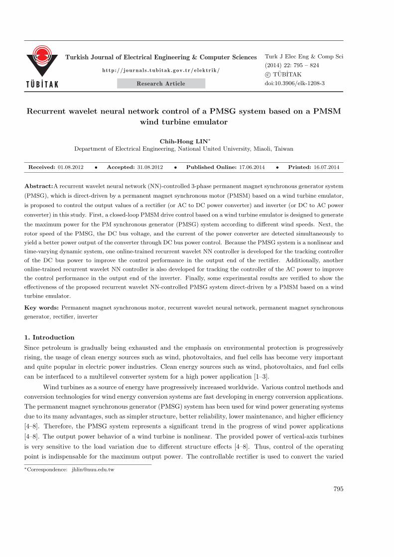
The characteristic curve of the wind power versus the rotor speed for the model of a wind turbine at different
wind speeds in the steady state, shown in Figure 1, is very important for a PMSG system direct-driven by a
PMSM. The power specification of the adopted 3-blade horizontal axis-type wind turbine in this paper is 1.5
kW and its diameter is 2 m. It is capable of obtaining the working point of the wind turbine that uses the
intersection point of the load characteristic curve and the turbine characteristic curve at a designated wind
speed. It is a very important characteristic curve as the shaft power of the wind turbine relates to the wind
speed v1 and rotor speed ωr1 to the maximum power tracking, as seen in Figure 1. For convenient usage and
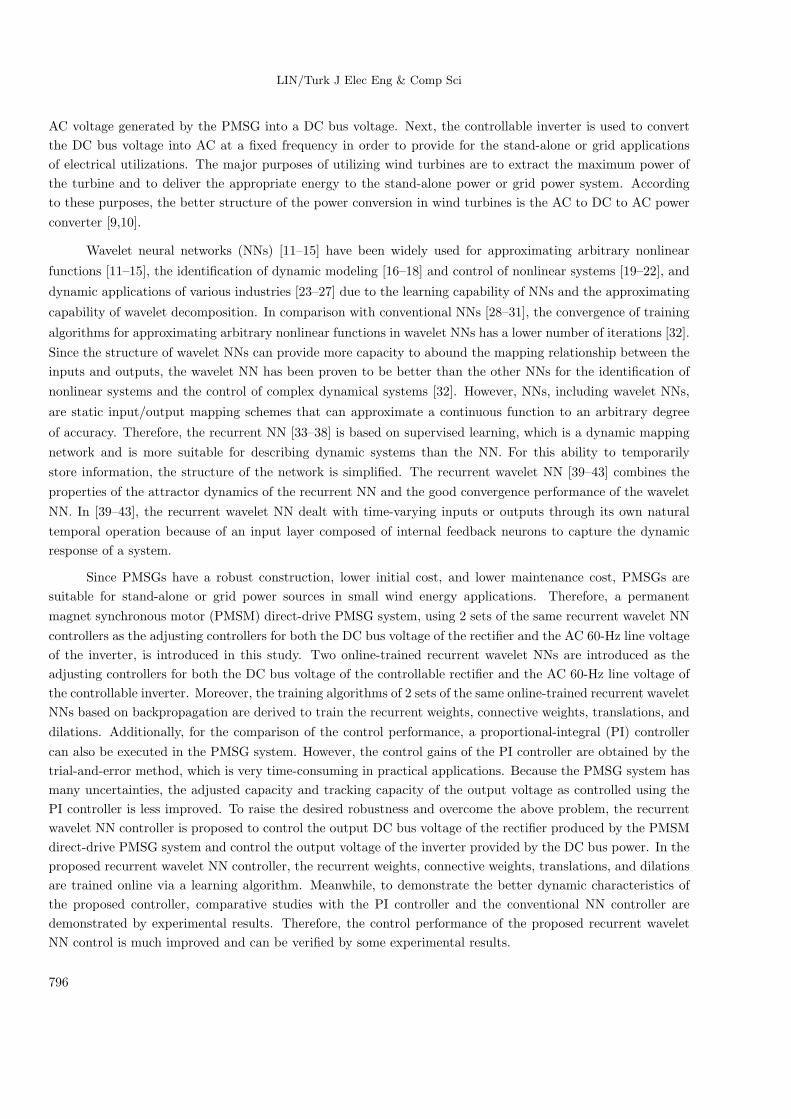
application, the characteristic curve shown in Figure 2 can also be expressed as the characteristic curve of the
wind turbine model. It represents the relationship curve between the coefficient Dp(β)of the power performance
and the tip speed ratio β . According to aerodynamic principles [1,4–7], the tip speed ratio β of the wind turbine
can be represented as:
Figure 1. Characteristic curves of wind power versus
rotor speed for the wind turbine model at different wind
speeds.
Figure 2. Characteristic curve of the coefficient Dp(β)
of power performance versus the tip ratio β for the wind
turbine.
β = r1 ω r1/v1, (1)
where β is the tip speed ratio of the wind turbine, r1 is the rotor radius of the wind turbine in meters, ωr1 is
the rotor speed of the wind turbine in rad/s, and v1 is the wind speed in m/s. The output mechanical power
P1 of the wind turbine can be expressed as [1,4–7]:
P1 = ρ1A1Dp(β)v31/2 = ρ1A1Dp(β)r
31ω
3r1/(2β
3), (2)
where ρ1 is the density of the air in kg/m3 and A1 is the undraped area in m2 . The generated torque of the
wind turbine for different wind speeds can be obtained from the Dp(β) − β curve in the modeling usage. It
797
LIN/Turk J Elec Eng & Comp Sci
is very important that the aerodynamic efficiency is maximum at the optimum tip speed ratio. The produced
torque of the wind turbine can be indicated as follows [1,4–7]:
T1 = P1/ωr1 = ρ1A1Dp(β)v31/(2ωr1) = ρ1A1R
31Dp(β)ω
2r1/(2β
3), (3)
where T1 is the produced torque of the wind turbine in Nm. The dynamic equation of the torque, which is the
produced torque T1 of the wind turbine subtracted by the electromagnetic torque Te1 of the PMSG, can be
represented as:
T1 − Te1 = J1dωr1
dt+B1ωr1, (4)
where J1 is the moment of inertia of the PMSG and B1 is the viscous friction coefficient of the PMSG.
2.2. Wind turbine emulator based on a PMSM
The wind turbine emulator that was proposed in [4–10] is adopted in this study in order to emulate the wind
turbine. Additionally, the adopted field-oriented controlled PMSM can emulate the power speed characteristic
curve of the wind turbine in this paper. In addition, a closed-loop robust speed controller, which can fight the
intrinsic nonlinear and time-varying characteristic of the PMSM drive, is adopted to adjust the rotor speed with
the relevant wind speed in order to emulate the wind variation.
2.3. Field-oriented controlled PMSG system
The voltage equations for the PMSG in the rotating reference frame can be indicated as follows [1,7–10]:
vq1 = −Rs1 iq1 − Lq1 iq1 − PωrLd1id1 + Pωr1λpm, (5)
vd1 = −Rs1 id1 − Ld1 id1 + Pωr1Lq1 iq1, (6)
where vd1 is the d−axis stator voltage, vq1 is theq−axis stator voltage, id1 is thed−axis stator current, iq1
is theq−axis stator current, Ld1 is the d−axis stator inductance, Lq1 is theq−axis stator inductance, Rs1 is
the stator resistance, and ωr1 is the rotor speed. A field-oriented control was adopted in [7–10]. Using the
field-oriented control, the d−axis stator current can be set to 0; that is, id = 0. Moreover, the electromagnetic
torque of the PMSG can be expressed as:
Te1 =3
2
P
2[λpmiq1 − (Ld1 − Lq1)id1iq1] =
3
2
P
2λpmiq1 = Ktiq1, (7)
where P is the number of poles, λpm is the permanent magnet flux linkage, and Kt = 3Pλpm/4is the torque
constant. For convenient analysis, the field-oriented controlled PMSG system is adopted. To emulate the
operation of the wind turbine, the primary machine’s PMSM is directly mounted to the PMSG. The control
principle of the PMSG system is based on field orientation. Due to Ld1 = Lq1 and id1 = 0 in the PMSG
system, the second term of Eq. (7) is 0. Moreover, λpm is constant for the field orientation control of the
PMSG system. The electromagnetic torque Te1 is a function of iq1 . The electromagnetic torque Te1 is linearly
proportional to the q -axis current iq1 . When the d−axis rotor flux is constant, the maximum electromagnetic
torque per ampere can be reached for the field-oriented control at the Te1 , proportional to iq1 .
798
LIN/Turk J Elec Eng & Comp Sci
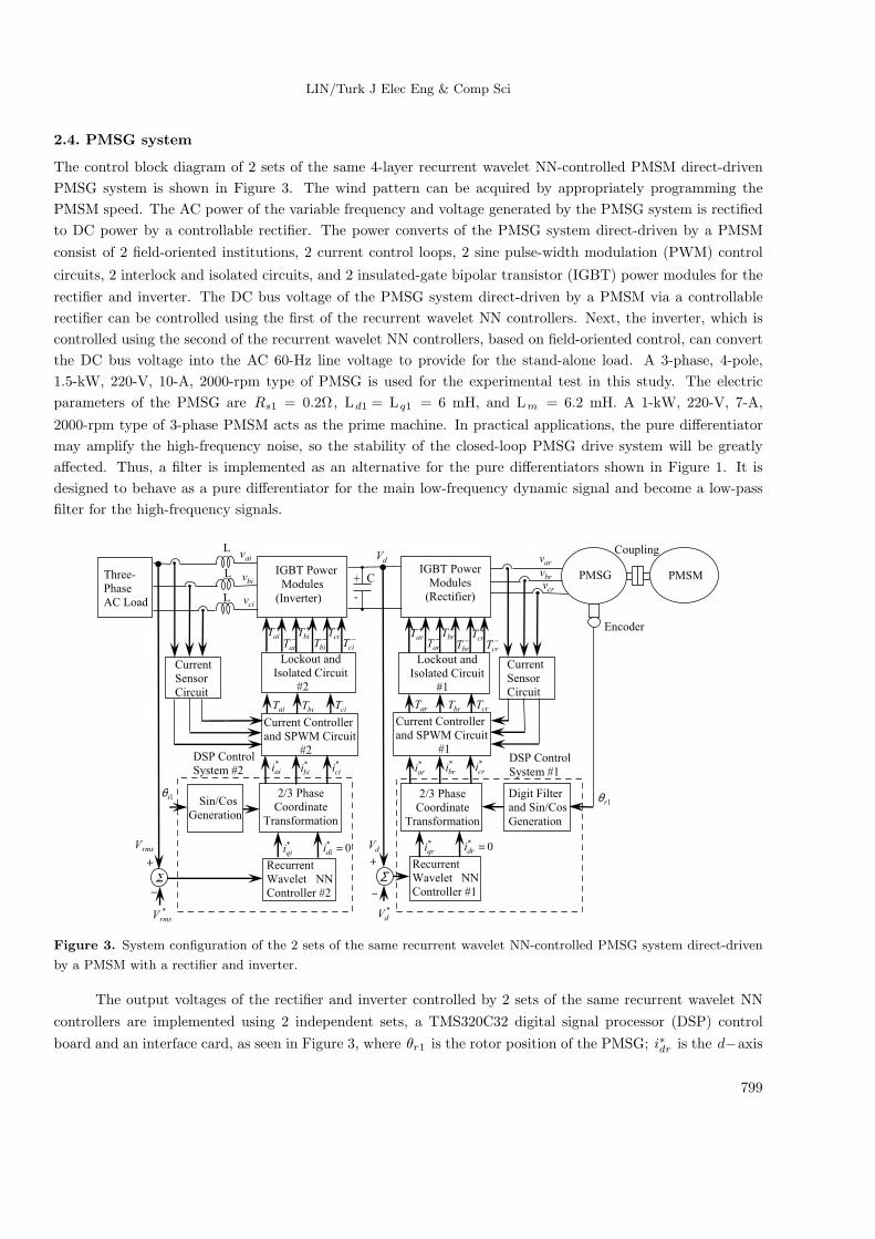
2.4. PMSG system
The control block diagram of 2 sets of the same 4-layer recurrent wavelet NN-controlled PMSM direct-driven
PMSG system is shown in Figure 3. The wind pattern can be acquired by appropriately programming the
PMSM speed. The AC power of the variable frequency and voltage generated by the PMSG system is rectified
to DC power by a controllable rectifier. The power converts of the PMSG system direct-driven by a PMSM
consist of 2 field-oriented institutions, 2 current control loops, 2 sine pulse-width modulation (PWM) control
circuits, 2 interlock and isolated circuits, and 2 insulated-gate bipolar transistor (IGBT) power modules for the
rectifier and inverter. The DC bus voltage of the PMSG system direct-driven by a PMSM via a controllable
rectifier can be controlled using the first of the recurrent wavelet NN controllers. Next, the inverter, which is
controlled using the second of the recurrent wavelet NN controllers, based on field-oriented control, can convert
the DC bus voltage into the AC 60-Hz line voltage to provide for the stand-alone load. A 3-phase, 4-pole,
1.5-kW, 220-V, 10-A, 2000-rpm type of PMSG is used for the experimental test in this study. The electric
parameters of the PMSG are Rs1 = 0.2Ω, Ld1 = Lq1 = 6 mH, and Lm = 6.2 mH. A 1-kW, 220-V, 7-A,
2000-rpm type of 3-phase PMSM acts as the prime machine. In practical applications, the pure differentiator
may amplify the high-frequency noise, so the stability of the closed-loop PMSG drive system will be greatly
affected. Thus, a filter is implemented as an alternative for the pure differentiators shown in Figure 1. It is
designed to behave as a pure differentiator for the main low-frequency dynamic signal and become a low-pass
filter for the high-frequency signals.
*ari
*bri
*cri
IGBT Power
Modules
(Inverter)
C
Encoder
arT brT
+
arT −
arT
+
brT−
brT
crT
+
crT −
crT
Lockout and
Isolated Circuit
#2
Current Controller
and SPWM Circuit
#2*aii
*bii
*cii
1iθ 2/3 Phase
Coordinate
Transformation
aiT biT ciT
+
aiT−
aiT
+
biT −
biT
+
ciT −
ciT
1rθDigit Filter
and Sin/Cos
Generation
*qri 0*
=dri
+
*dV
dV
−
Σ
Three-
Phase
AC Load
Current
Sensor
Circuit
DSP Control
System #2
*qii 0*
=dii
+
*rmsV
rmsV
−
Σ
Sin/Cos
Generation
+
-
L
L
dV arv
crvbrv
aiv
biv
civ
IGBT Power
Modules
(Rectifier)
Current
Sensor
Circuit
Current Controller
and SPWM Circuit
#1DSP Control
System #1
2/3 Phase
Coordinate
Transformation
Lockout and
Isolated Circuit
#1
Recurrent
Wavelet NN
Controller #1
Recurrent
Wavelet NN
Controller #2
Coupling L
PMSG PMSM
Figure 3. System configuration of the 2 sets of the same recurrent wavelet NN-controlled PMSG system direct-driven
by a PMSM with a rectifier and inverter.
The output voltages of the rectifier and inverter controlled by 2 sets of the same recurrent wavelet NN
controllers are implemented using 2 independent sets, a TMS320C32 digital signal processor (DSP) control
board and an interface card, as seen in Figure 3, where θr1 is the rotor position of the PMSG; i∗dr is the d−axis
799
LIN/Turk J Elec Eng & Comp Sci
control current of the rectifier; i∗qr is the q−axis control current of the rectifier; i∗ar , i∗br , and i∗cr are the desired
phase currents of the PMSG in phases ar, br, and cr, respectively; iar , ibr , and icr are the actual measured
phase currents of the PMSG in phases ar, br, and cr, respectively; Tar , Tbr , and Tcr are the sinusoidal PWM
control signals of the rectifier in phases ar, br, and cr, respectively; Vd is the actual measured magnitude of the
DC bus voltage in the output end of the rectifier; V ∗d is the desired magnitude of the DC bus voltage in the
output end of the rectifier; i∗di is the d−axis control current of the inverter; i∗qi is the q−axis control current
of the inverter; θi1 is the electric angular angle of the inverter, which integrates the command electric angular
frequency with respect tot ; i∗ai , i∗bi , and i∗ci are the desired phase currents of the inverter in phases ai, bi, and
ci, respectively; iai , ibi , and ici are the actual measured phase currents of the inverter in phases ai, bi, and ci,
respectively; vai , vbi , and vci are the actual measured phase voltages of the inverter in phases ai, bi, and ci ;
respectively; Tai , Tbi , and Tci are the sinusoidal PWM control signals of the inverter in phases ai, bi, and ci,
respectively; Vrms is the actual root-mean-square magnitude of the AC 60-Hz line voltage in the output end of
the inverter; and V ∗rms is the desired root-mean-square magnitude of the AC 60-Hz line voltage in the output
end of the inverter.
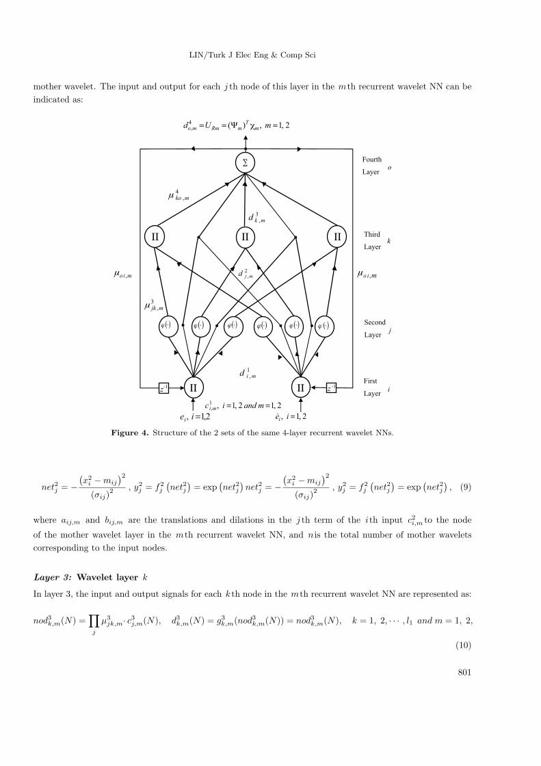
3. Recurrent wavelet NN controller
3.1. Description of recurrent wavelet NN
The 2 proposed sets of the same 2-layer recurrent wavelet NNs, with an input layer using feedback signals from
the output layer, are taken into account to result in better learning efficiency. The architecture of the 2 sets of
the same 4-layer recurrent wavelet NNs, which consists of layer 1, the input layer; layer 2, the mother wavelet
layer; layer 3, the wavelet layer; and layer 4, the output layer, is shown in Figure 4. The exciting functions and
signal propagations of the nodes in each layer of the recurrent wavelet NN are explained as follows:
Layer 1: Input layer i
In layer 1, the input and output signals for each i node in the mth recurrent wavelet NN can be denoted as:
nod1i,m(N) =∏oc1i ,m(N) · µoi, m · d4o, m(N − 1),
d1i,m(N) = g1i,m(nod1i,m(N)) = nod1i,m(N), i = 1, 2 and m = 1, 2,(8)
where c1i,m is the input of theith node in the mth recurrent wavelet NN and d1i,m is the output of the
ith node in the mth recurrent wavelet NN. The different inputs of the 2 sets of recurrent wavelet NNs are
c11,1 = e1 = V ∗d − Vd , c
12,1 = e1 for the rectifier end of the PMSG system in the first recurrent wavelet NN, and
c11, 2 = e2 = V ∗rms − Vrms , c
12,2 = e2 for the inverter end of the PMSG system in the second recurrent wavelet
NN, respectively. N indicates the number of iterations. The connecting weight µoi, m is the recurrent weight
between the output layer and the input layer in the mth recurrent wavelet NN. d4o,m is the output value of the
output layer in the mth recurrent wavelet NN.
Layer 2: Mother wavelet layer j
In layer 2, each node implements a wavelet ϕ (x) that is derived from its mother wavelet. In this paper, the
first derivative of the Gaussian wavelet function net2j = − (x2i−mij)
2
(σij)2 , y2j = f2j
(net2j
)= exp
(net2j
)is adopted
as a mother wavelet. A family of wavelets is constructed by translations and dilations implemented on the
800
LIN/Turk J Elec Eng & Comp Sci
mother wavelet. The input and output for each j th node of this layer in the mth recurrent wavelet NN can be
indicated as:
Third
Layer
Second
Layer
Fourth
Layer
First
Layeri
j
k
o
3,mjkμ
4,mkoμ
1,mid
2,mjd
3,mkd
2,12,1,1, == mandic mi
-1 -1z
2,1,)(4, === mUd m
TmRmmo χΨ
2,1, =iei 2,1, =ieiɺ
mio ,μ mio ,μ
( )⋅ϕ ( )⋅ϕ ( )⋅ϕ ( )⋅ϕ ( )⋅ϕ ( )⋅ϕ
∑
z -1II II
IIIIII
Figure 4. Structure of the 2 sets of the same 4-layer recurrent wavelet NNs.
net2j = −(x2i −mij
)2(σij)
2 , y2j = f2j(net2j
)= exp
(net2j
)net2j = −
(x2i −mij
)2(σij)
2 , y2j = f2j(net2j
)= exp
(net2j
), (9)
where aij,m and bij,m are the translations and dilations in the j th term of the ith input c2i,m to the node
of the mother wavelet layer in the mth recurrent wavelet NN, and n is the total number of mother wavelets
corresponding to the input nodes.
Layer 3: Wavelet layer k
In layer 3, the input and output signals for each k th node in the mth recurrent wavelet NN are represented as:
nod3k,m(N) =∏j
µ3jk,m· c3j,m(N), d3k,m(N) = g3k,m(nod3k,m(N)) = nod3k,m(N), k = 1, 2, · · · , l1 and m = 1, 2,
(10)
801
LIN/Turk J Elec Eng & Comp Sci
where c3j,m represents the j th input to the node of layer 3 in the mth recurrent wavelet NN and µ3jk,m is the
weight between the mother wavelet layer and the wavelet layer in the mth recurrent wavelet NN. They are
supposed to be unity; l1 is the total number of wavelets if each input node has the same mother wavelet nodes.
Layer 4: Output layer o
In layer 4, the input and output signals for the oth node in the mth recurrent wavelet NN are expressed as:
nod4o,m(N) =∑k
µ4ko,m · c4k,m(N), d4o,m(N) = g4o,m(nod4o,m(N)) = nod4o,m(N), o = 1 and m = 1, 2. (11)
The connecting weights µ4ko,m are the output action intensity of the oth output associated with the k th node
in the mth recurrent wavelet NN; c4k,m represents the k th input to the node in layer 4 in the mth recurrent
wavelet NN. The single oth node in this layer is represented as ?. The outputs in the mth recurrent wavelet
NN can be represented as d4o,m .
d4o,m = (ψm)Tχm, m = 1, 2 (12)
The output values of the 2 sets of the same 4-layer recurrent wavelet NNs can be rewritten as UR 1 =
(ψ1)Tχ1 = i∗qr for the rectifier end and UR 2 = (ψ2)
Tχ2 = i∗qi for the inverter end. Two vectors, ψ1 =[µ411,1 µ
421,1 · · · µ4
l1,1
]T
and ψ2 =[µ411,2 µ
421,2 · · · µ4
l1,2
]T
, are to be the adjusted parameters between
the mother layer and the output layer of the 2 sets of the same 4-layer recurrent wavelet NNs. χm =[c41,m c42,m · · · c4l,m
]T, m = 1, 2 are the inputs vectors in the output layer of the 2 sets of the same 4-layer re-
current wavelet NNs, in which c4k,m are determined by the selected mother wavelet function and 0 ≤ c4k,m ≤ 1.
To explain the online learning algorithm of the recurrent wavelet NN using the supervised gradient decent
method, first, the energy function Vc,m is defined as:
Vc,m =1
2e2m, m = 1, 2, (13)
where e1 is equal to V ∗d − Vd in the rectifier end of the PMSG system and e2 is equal to V ∗
rms − Vrms in the
inverter end of the PMSG system. Next, the learning algorithm is described as follows:
Layer 4: The propagated error term in the mth recurrent wavelet NN is:
υ4m = − ∂ Vc,m∂nod4o,m
, m = 1, 2 . (14)
Next, the variation ∆µ4ko,m of the connective weights in the mth recurrent wavelet NN can be calculated as:
∆µ4ko,m = −γm
∂ Vc,m∂d4o,m
∂ d4o,m∂ nod4o,m
∂ nod4o,m∂ µ4
ko,m
= −γm · υ4m · c4k,m, m = 1, 2, (15)
where γm is the learning rate in the mth recurrent wavelet NN. The connective weights µ4ko,m in the mth
recurrent wavelet NN can be renewed according to the following equation:
µ4ko,m(N + 1) = µ4
ko,m(N) + ∆µ4ko,m, m = 1, 2. (16)
802
LIN/Turk J Elec Eng & Comp Sci
Layer 3: To reduce the loading of the computation, all of the connective weights are set as 1 in this
layer. The error term in the mth recurrent wavelet NN can be calculated as:
υ3k,m ∆ − ∂ Vc,m∂ d4o,m
∂ d4o,m∂ nod4o,m
∂ nod4o,m∂ d3k,m
∂ d3k,m∂ nod3k,m
= υ4m · µ4ko,m(N), m = 1, 2. (17)
Layer 2: The propagated error term in the mth recurrent wavelet NN is:
υ2j,m ∆ − ∂ Vc,m∂ d4o,m
∂ d4o,m∂ nod4o,m
∂ nod4o,m∂ d3k,m
∂ d3k,m∂ nod3k,m
∂ nod3k,m∂ d2j,m
∂ d2j,m∂ nod2j,m
=∑k
υ3k,m · d3k,m(N), m = 1, 2. (18)
The variation ∆a ij,m of the translations and the variation ∆bij,m of the dilations in the Gaussian wavelet
function in the mth recurrent wavelet NN using the chain rule can be calculated as:
⇒ ∆mij =(− ∂ E
∂ mij
)=
[− ∂ E
∂ f4o (net
4o)
· ∂ f4o (net
4o)
∂ net4o· ∂ net4o∂ f3
k(net3k)· ∂ f3
k(net3k)
∂ net3k
]·[
∂ net3k∂ f2
j (net2j)· ∂ f2
j (net2j)
∂ net2j· ∂ net2j
∂ mij
]= δ2j ·
2·(x2i−mij)
(σij)2
, (19)
⇒ ∆mij =(− ∂ E
∂ mij
)[− ∂ E
∂ f4o (net
4o)
· ∂ f4o (net
4o)
∂ net4o· ∂ net4o∂ f3
k(net3k)· ∂ f3
k(net3k)
∂ net3k
]·[
∂ net3k∂ f2
j (net2j)· ∂ f2
j (net2j)
∂ net2j· ∂ net2j
∂ mij
]= δ2j ·
2·(x2i−mij)
(σij)2
. (20)
The translations aij,m and dilations bij ,m in the mth recurrent wavelet NN can be renewed according to the
following equations:
aij,m(N + 1) = aij,m(N) + ∆aij,m, m = 1, 2, (21)
bij,m(N + 1) = bij,m(N) + ∆bij,m, m = 1, 2. (22)
The variation ∆µoi,m of the recurrent weights in the mth recurrent wavelet NN using the chain rule and the
gradient descent method can be renewed as:
∆µoi,m = − ∂ Vc,m∂ nod2j,m
∂ nod2j,m∂ d1i,m
∂ d1i,m∂ nod1i,m
∂ nod1i,m∂ µoi,m
=∑j
υ2j,m[ (c2i,m(N) · aij,m) · c1i,m(N) · id4o,m(N − 1)]
bij,m, m = 1, 2. (23)
The recurrent weights µoi,m in the mth recurrent wavelet NN can be renewed according to the following
equation:
µoi,m(N + 1) = µoi,m(N) + ∆µoi,m, m = 1, 2. (24)
Due to the uncertainty effect of the system dynamics, the accurate computation of the Jacobian∂ Vc,m
∂ d4o,m
, m =
1, 2 in the PMSG system cannot be determined. To dispel the difficulty and handle the above matter, use of
803
LIN/Turk J Elec Eng & Comp Sci
the delta adaptation law [44] can raise the online learning capacity of the connective weights. Therefore, the
delta adaptation law can be calculated as:
υ4m = em + em, m = 1, 2. (25)
3.2. Convergence analyses
The selection of the values for the learning-rate parameters has a significant effect on the network performance.
In order to train the recurrent wavelet NN effectively, the varied learning rate, which guarantees the convergence
of the output error based on the analyses of a discrete-type Lyapunov function, is derived in this section. The
convergence analysis in this study is to derive a specific learning-rate parameter for specific types of network
parameters to assure the convergence of the output error [35].
Theorem 1 Let γm be the learning-rate parameter of the mth recurrent wavelet NN and let Pwmax,m be
defined as Pwmax,m ≡ maxN ∥Pw,m (N)∥ , where Pw,m (N) = ∂ d4o,m
/∂ µ4
ko,m in the mth recurrent wavelet NN
and ∥ · ∥ is the Euclidean norm in ℜn . The convergence is guaranteed if γm is chosen as γm = λm/(P 2wmax,m
)=
λm/Ru,m , in which λm is a positive constant gain and Ru,m is the number of nodes in wavelet layer of the
mth recurrent wavelet NN.
Proof. Since
Pw,m (N) =∂ d4o,m∂ µ4
ko,m
= c4k,m, (26)
thus
∥Pw,m (N)∥ <√Ru,m. (27)
Next, a discrete-type Lyapunov function is selected as:
Vm (N) =1
2e2m (N) . (28)
The change in the Lyapunov function is obtained by:
∆Vm (N) = Vm (N + 1)− Vm (N) =1
2
[e2m (N + 1)− e2m (N)
]. (29)
The error difference can be represented by [35]:
em (N + 1) = em (N) + ∆em (N) = em (N) +
[∂ em (N)
∂ µ4ko,m
]T
∆µ4ko,m, (30)
where ∆µ4ko,m represents a weight change in the output layer. Using Eqs. (14), (15), and (30), then:
∂ em (N)
∂ µ4ko,m
=∂ em (N)
∂ d4o,m
∂ d4o,m∂ µ4
ko,m
= −υ4o,mem (N)
Pw,m (N) , (31)
em (N + 1) = em (N)−
[µ4o,m
em (N)Pw,m (N)
]T
γm µ4o,m Pw,m (N) . (32)
804
LIN/Turk J Elec Eng & Comp Sci
Then:
∥em (N + 1)∥ =
∥∥∥∥em (N)
[1− γm
(µ4o,m
/em (N)
)2
PTw,m (N)Pw,m (N)
]∥∥∥∥≤ ∥e (N)∥
∥∥∥∥1− γm
(µ4o,m
/em (N)
)2
PTw,m (N)Pw,m (N)
∥∥∥∥ . (33)
If ηw is chosen as λm = λm/(P 2wmax,m
)= λm/Ru,m , the term
∥∥∥∥1− γm
(µ4o,k
/em (N)
)2
PTw,m (N)Pw,m (N)
∥∥∥∥in Eq. (33) is less than 1. Therefore, the Lyapunov stability of Vm > 0 and ∆V m < 0 is guaranteed. The
output error between the reference model and the actual system will converge to 0, as t→ ∞ . This completes
the proof of the theorem.
Remark The values of the learning rate parameter γm are dependent on the selection of the value λm .
4. Experimental results
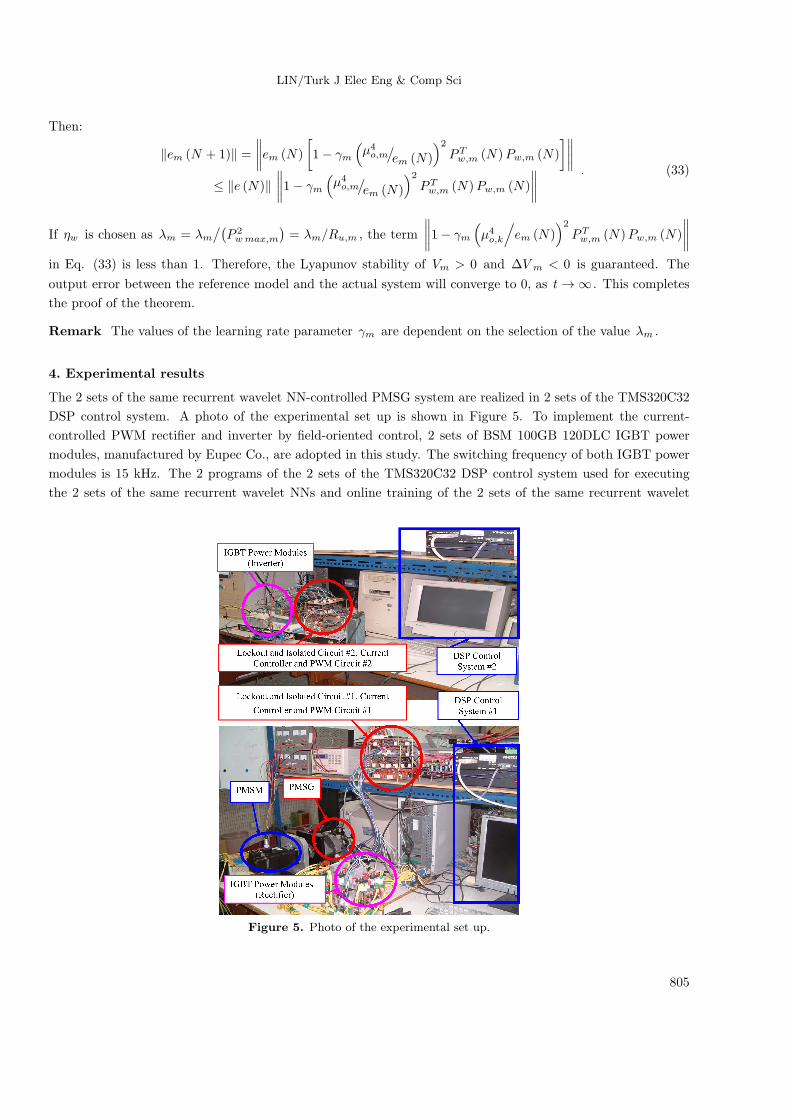
The 2 sets of the same recurrent wavelet NN-controlled PMSG system are realized in 2 sets of the TMS320C32
DSP control system. A photo of the experimental set up is shown in Figure 5. To implement the current-
controlled PWM rectifier and inverter by field-oriented control, 2 sets of BSM 100GB 120DLC IGBT power
modules, manufactured by Eupec Co., are adopted in this study. The switching frequency of both IGBT power
modules is 15 kHz. The 2 programs of the 2 sets of the TMS320C32 DSP control system used for executing
the 2 sets of the same recurrent wavelet NNs and online training of the 2 sets of the same recurrent wavelet
Figure 5. Photo of the experimental set up.
805
LIN/Turk J Elec Eng & Comp Sci
NNs need 2-ms sampling intervals. Furthermore, to show the effectiveness of the control system and training
performance, the 2 kinds of recurrent wavelet NNs with 2 different nodes are provided in the experimentation.
The first kind of recurrent wavelet NN has 2, 10, 5, and 1 nodes in layers 1, 2, 3, and 4, respectively. The second
kind of recurrent wavelet NN has 2, 14, 7, and 1 nodes in layers 1, 2, 3, and 4, respectively. To initialize the
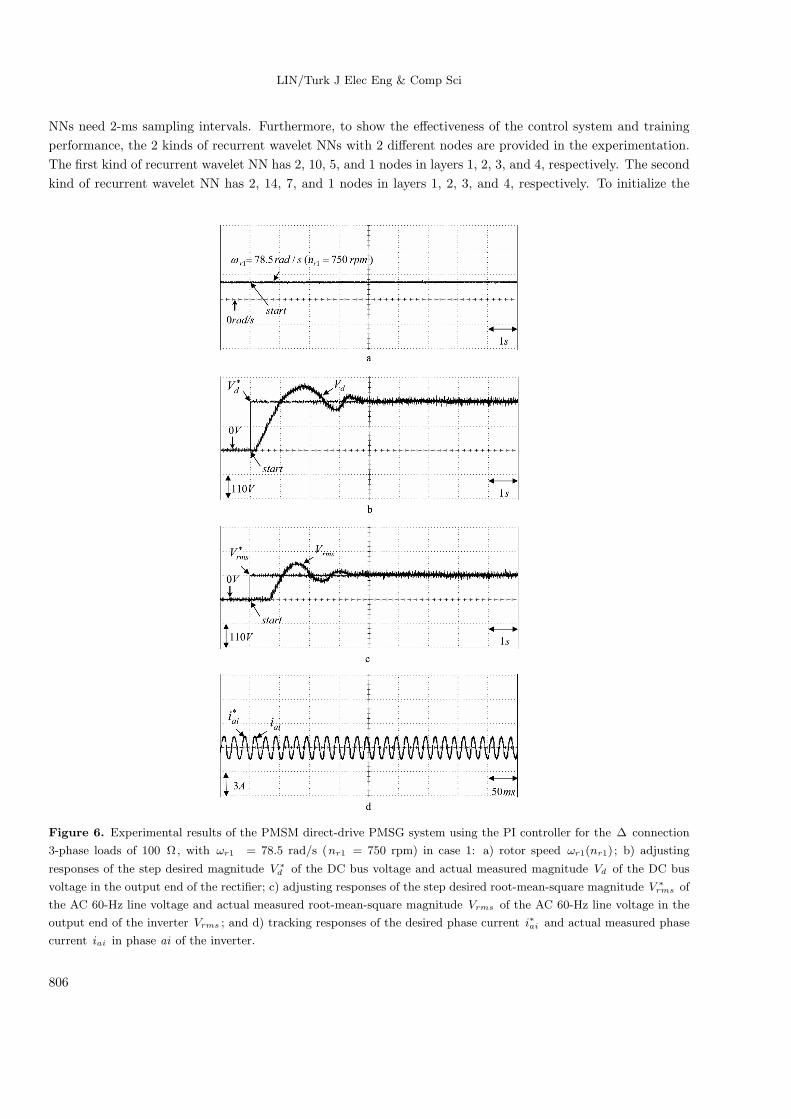
Figure 6. Experimental results of the PMSM direct-drive PMSG system using the PI controller for the ∆ connection
3-phase loads of 100 Ω, with ωr1 = 78.5 rad/s (nr1 = 750 rpm) in case 1: a) rotor speed ωr1(nr1) ; b) adjusting
responses of the step desired magnitude V ∗d of the DC bus voltage and actual measured magnitude Vd of the DC bus
voltage in the output end of the rectifier; c) adjusting responses of the step desired root-mean-square magnitude V ∗rms of
the AC 60-Hz line voltage and actual measured root-mean-square magnitude Vrms of the AC 60-Hz line voltage in the
output end of the inverter Vrms ; and d) tracking responses of the desired phase current i∗ai and actual measured phase
current iai in phase ai of the inverter.
806
LIN/Turk J Elec Eng & Comp Sci
parameters of the wavelets, the initialization of the recurrent wavelet NN parameters is adopted reference [45].
The effect due to the inaccurate selection of the initialized parameters can be retrieved by the online parameter
training methodology. The parameter adjustment process remains continually active for the duration of the
experimentation. To verify the control performance of the proposed 2 sets of the same recurrent wavelet NN-
controlled PMSG system direct-driven by a PMSM based on a wind turbine emulator, 2 cases with field-oriented
control currents of i∗di = 0A and i∗dr = 0A are tested. To show the adjusting and tracking responses for the
stand-alone power application, 3 cases are selected. Case 1 is the ∆ connection 3-phase load 100 Ω and the
rotor speed ωr1 (nr1), step desired magnitude V ∗d of the DC bus voltage, and step desired root-mean-square
magnitude V ∗rms of the AC 60-Hz line voltage are set as 78.5 rad/s (750 rpm), 220 V, and 110 V, respectively.
Case 2 is the ∆ connection 3-phase load 50 Ω and the rotor speed ωr1 , desired magnitude V ∗d of the DC bus
voltage, and desired root-mean-square magnitude V ∗rms of the AC 60-Hz line voltage are set as 157 rad/s (nr1
= 1500 rpm), 220 V, and 110 V, respectively. Case 3 is the ∆ connection 3-phase load 18 Ω and the rotor
speed ωr1 , desired magnitude V ∗d of the DC bus voltage, and desired root-mean-square magnitude V ∗
rms of the
AC 60-Hz line voltage are set as 209.3 rad/s (2000 rpm), 220 V, and 110 V, respectively. The ∆ connection
3-phase loads of the 100 Ω, 50 Ω, and 18 Ω dispatched powers are 121 W, 242 W, and 672 W, respectively.
Some experimental results of the PI-controlled PMSM direct-drive PMSG system are demonstrated for the
comparison of the control performance. Since the PMSG system is a nonlinear time-varying system, the gains
of the PI controllers for both the DC bus voltage adjustment and AC 60-Hz line voltage adjustment are obtained
by trial and error to achieve steady-state control performance. The control gains are Kp = 5.2, Ki = 10.2 for
the DC bus voltage adjustment and Kp = 4.8, Ki = 10.8 for the AC 60-Hz line voltage adjustment in the 2
sets of PI controllers. The experimental results of the PI-controlled PMSM direct-driven PMSG system for the
∆ connection 3-phase loads of 100 Ω with ωr1 = 78.5 rad/s (nr1 = 750 rpm) in case 1 are shown in Figure 6,
where the rotor speed ωr1 (nr1) is shown in Figure 6a; the adjusting responses of the step desired magnitude
V ∗d of the DC bus voltage and actual measured magnitude Vd of the DC bus voltage in the output end of
the rectifier are shown in Figure 6b; the adjusting responses of the step desired root-mean-square magnitude
V ∗rms of the AC 60-Hz line voltage and actual measured root-mean-square magnitude Vrms of the AC 60-Hz
line voltage in the output end of the inverter are shown in Figure 6c; and the tracking responses of the desired
phase current i∗ai and actual measured phase current iai in phase ai of the inverter are shown in Figure 6d.
The experimental results of the PI-controlled PMSM direct-driven PMSG system for the ∆ connection 3-phase
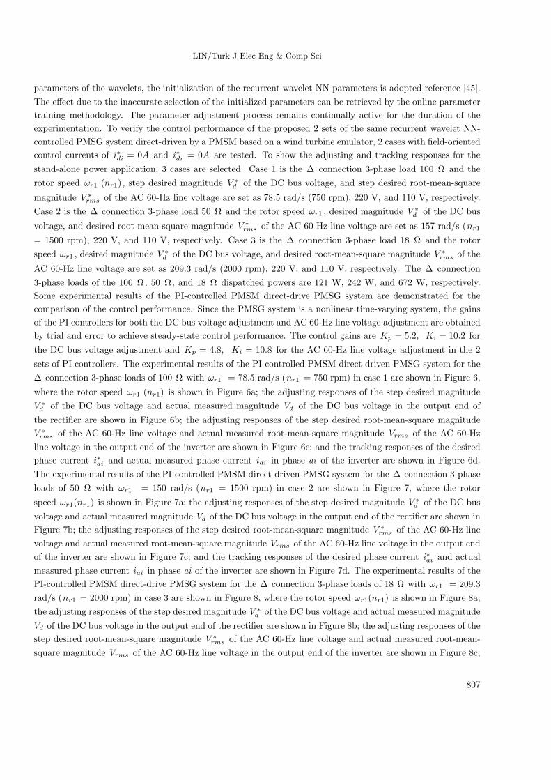
loads of 50 Ω with ωr1 = 150 rad/s (nr1 = 1500 rpm) in case 2 are shown in Figure 7, where the rotor
speed ωr1(nr1) is shown in Figure 7a; the adjusting responses of the step desired magnitude V ∗d of the DC bus
voltage and actual measured magnitude Vd of the DC bus voltage in the output end of the rectifier are shown in
Figure 7b; the adjusting responses of the step desired root-mean-square magnitude V ∗rms of the AC 60-Hz line
voltage and actual measured root-mean-square magnitude Vrms of the AC 60-Hz line voltage in the output end
of the inverter are shown in Figure 7c; and the tracking responses of the desired phase current i∗ai and actual
measured phase current iai in phase ai of the inverter are shown in Figure 7d. The experimental results of the
PI-controlled PMSM direct-drive PMSG system for the ∆ connection 3-phase loads of 18 Ω with ωr1 = 209.3
rad/s (nr1 = 2000 rpm) in case 3 are shown in Figure 8, where the rotor speed ωr1(nr1) is shown in Figure 8a;
the adjusting responses of the step desired magnitude V ∗d of the DC bus voltage and actual measured magnitude
Vd of the DC bus voltage in the output end of the rectifier are shown in Figure 8b; the adjusting responses of the
step desired root-mean-square magnitude V ∗rms of the AC 60-Hz line voltage and actual measured root-mean-
square magnitude Vrms of the AC 60-Hz line voltage in the output end of the inverter are shown in Figure 8c;
807
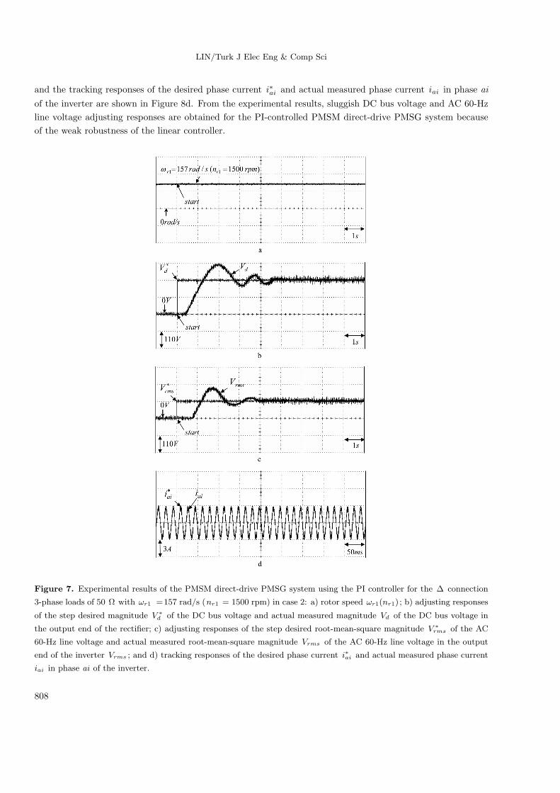
LIN/Turk J Elec Eng & Comp Sci
and the tracking responses of the desired phase current i∗ai and actual measured phase current iai in phase ai
of the inverter are shown in Figure 8d. From the experimental results, sluggish DC bus voltage and AC 60-Hz
line voltage adjusting responses are obtained for the PI-controlled PMSM direct-drive PMSG system because
of the weak robustness of the linear controller.
Figure 7. Experimental results of the PMSM direct-drive PMSG system using the PI controller for the ∆ connection
3-phase loads of 50 Ω with ωr1 =157 rad/s (nr1 = 1500 rpm) in case 2: a) rotor speed ωr1(nr1) ; b) adjusting responses
of the step desired magnitude V ∗d of the DC bus voltage and actual measured magnitude Vd of the DC bus voltage in
the output end of the rectifier; c) adjusting responses of the step desired root-mean-square magnitude V ∗rms of the AC
60-Hz line voltage and actual measured root-mean-square magnitude Vrms of the AC 60-Hz line voltage in the output
end of the inverter Vrms ; and d) tracking responses of the desired phase current i∗ai and actual measured phase current
iai in phase ai of the inverter.
808
LIN/Turk J Elec Eng & Comp Sci
Figure 8. Experimental results of the PMSM direct-drive PMSG system using the PI controller for the ∆ connection
3-phase loads of 18 Ω with ωr1 = 209.3 rad/s (nr1 =2000 rpm) in case 3: a) rotor speed ωr1(nr1) ; b) adjusting
responses of the step desired magnitude V ∗d of the DC bus voltage and actual measured magnitude Vd of the DC bus
voltage in the output end of the rectifier; c) adjusting responses of the step desired root-mean-square magnitude V ∗rms of
the AC 60-Hz line voltage and actual measured root-mean-square magnitude Vrms of the AC 60-Hz line voltage in the
output end of the inverter Vrms ; and d) tracking responses of the desired phase current i∗ai and actual measured phase
current iai in phase ai of the inverter.
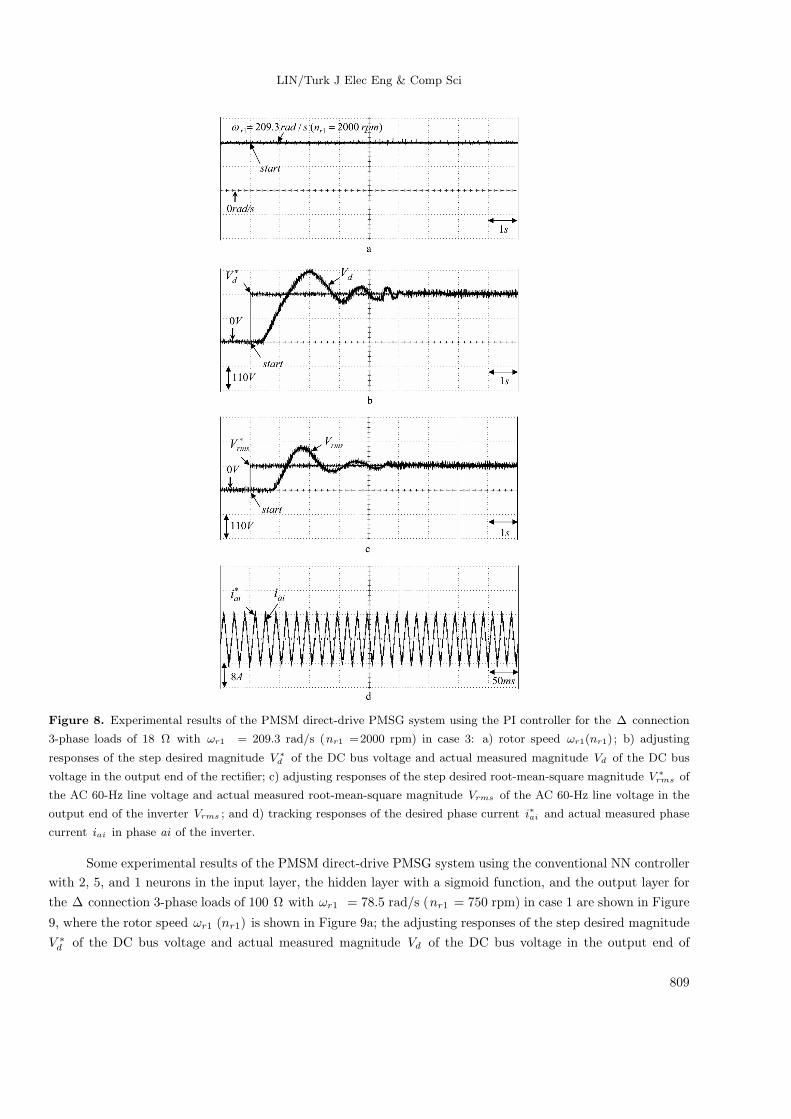
Some experimental results of the PMSM direct-drive PMSG system using the conventional NN controller
with 2, 5, and 1 neurons in the input layer, the hidden layer with a sigmoid function, and the output layer for
the ∆ connection 3-phase loads of 100 Ω with ωr1 = 78.5 rad/s (nr1 = 750 rpm) in case 1 are shown in Figure
9, where the rotor speed ωr1 (nr1) is shown in Figure 9a; the adjusting responses of the step desired magnitude
V ∗d of the DC bus voltage and actual measured magnitude Vd of the DC bus voltage in the output end of
809
LIN/Turk J Elec Eng & Comp Sci
the rectifier are shown in Figure 9b; the adjusting responses of the step desired root-mean-square magnitude
V ∗rms of the AC 60-Hz line voltage and actual measured root-mean-square magnitude Vrms of the AC 60-Hz
line voltage in the output end of the inverter are shown in Figure 9c; and the tracking responses of the desired
phase current i∗ai and actual measured phase current iai in phase ai of the inverter are shown in Figure 9d.
Figure 9. Experimental results of the PMSM direct-drive PMSG system using the conventional NN controller for the
∆ connection 3-phase loads of 100 Ω with ωr1 = 78.5 rad/s (nr1 = 750 rpm) in case 1: a) rotor speed ωr1(nr1) ; b)
adjusting responses of the step desired magnitude V ∗d of the DC bus voltage and actual measured magnitude Vd of the
DC bus voltage in the output end of the rectifier; c) adjusting responses of the step desired root-mean-square magnitude
V ∗rms of the AC 60-Hz line voltage and actual measured root-mean-square magnitude Vrms of the AC 60-Hz line voltage
in the output end of the inverter Vrms ; and d) tracking responses of the desired phase current i∗ai and actual measured
phase current iai in phase ai of the inverter.
810
LIN/Turk J Elec Eng & Comp Sci
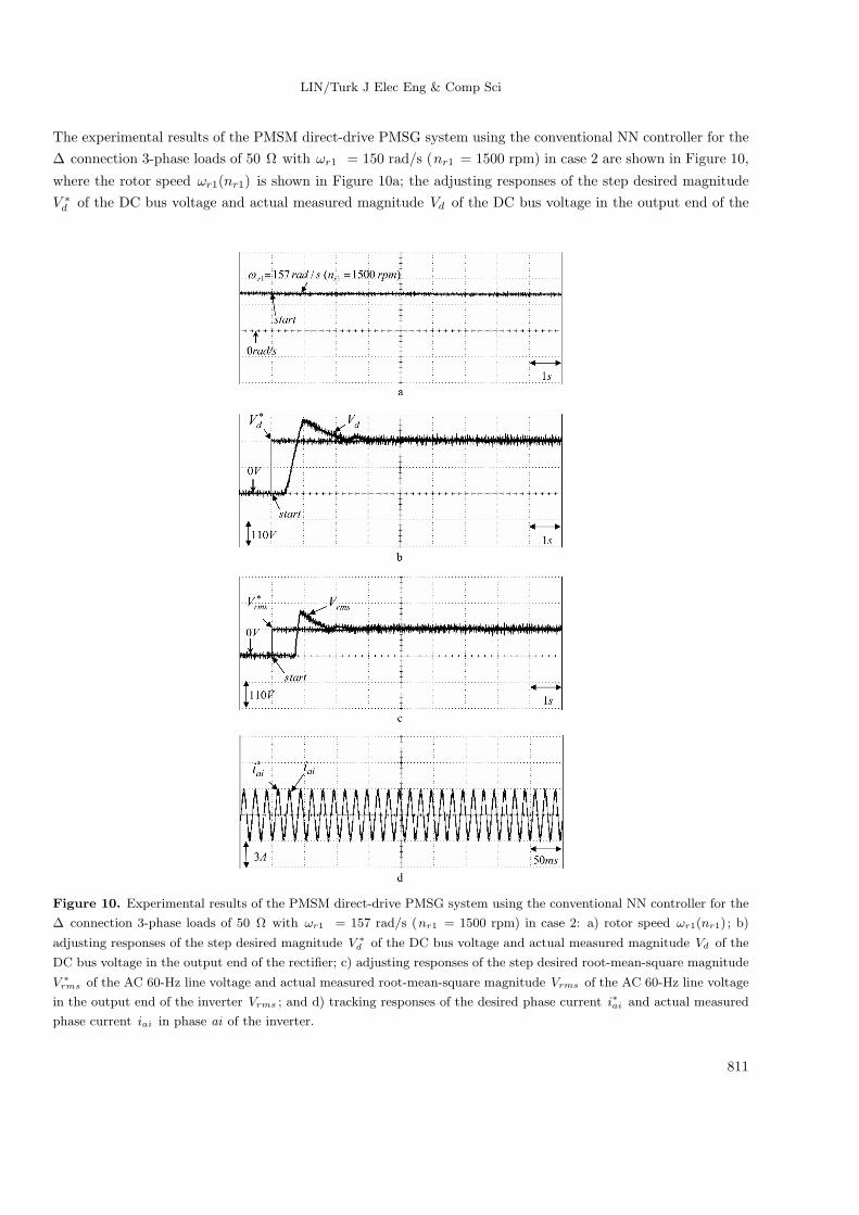
The experimental results of the PMSM direct-drive PMSG system using the conventional NN controller for the
∆ connection 3-phase loads of 50 Ω with ωr1 = 150 rad/s (nr1 = 1500 rpm) in case 2 are shown in Figure 10,
where the rotor speed ωr1(nr1) is shown in Figure 10a; the adjusting responses of the step desired magnitude
V ∗d of the DC bus voltage and actual measured magnitude Vd of the DC bus voltage in the output end of the
Figure 10. Experimental results of the PMSM direct-drive PMSG system using the conventional NN controller for the
∆ connection 3-phase loads of 50 Ω with ωr1 = 157 rad/s (nr1 = 1500 rpm) in case 2: a) rotor speed ωr1(nr1) ; b)
adjusting responses of the step desired magnitude V ∗d of the DC bus voltage and actual measured magnitude Vd of the
DC bus voltage in the output end of the rectifier; c) adjusting responses of the step desired root-mean-square magnitude
V ∗rms of the AC 60-Hz line voltage and actual measured root-mean-square magnitude Vrms of the AC 60-Hz line voltage
in the output end of the inverter Vrms ; and d) tracking responses of the desired phase current i∗ai and actual measured
phase current iai in phase ai of the inverter.
811
LIN/Turk J Elec Eng & Comp Sci
rectifier are shown in Figure 10b; the adjusting responses of step desired root-mean-square magnitude V ∗rms of
the AC 60-Hz line voltage and actual measured root-mean-square magnitude Vrms of the AC 60-Hz line voltage
in the output end of the inverter are shown in Figure 10c; and the tracking responses of the desired phase
current i∗ai and actual measured phase current iai in phase ai of the inverter are shown in Figure 10d. The
Figure 11. Experimental results of the PMSM direct-drive PMSG system using the conventional NN controller for the
∆ connection 3-phase loads of 18 Ω with ωr1 =209.3 rad/s (nr1 = 2000 rpm) in case 3: a) rotor speed ωr1(nr1) ; b)
adjusting responses of the step desired magnitude V ∗d of the DC bus voltage and actual measured magnitude Vd of the
DC bus voltage in the output end of the rectifier; c) adjusting responses of the step desired root-mean-square magnitude
V ∗rms of the AC 60-Hz line voltage and actual measured root-mean-square magnitude Vrms of the AC 60-Hz line voltage
in the output end of the inverter Vrms ; and d) tracking responses of the desired phase current i∗ai and actual measured
phase current iai in phase ai of the inverter.
812
LIN/Turk J Elec Eng & Comp Sci
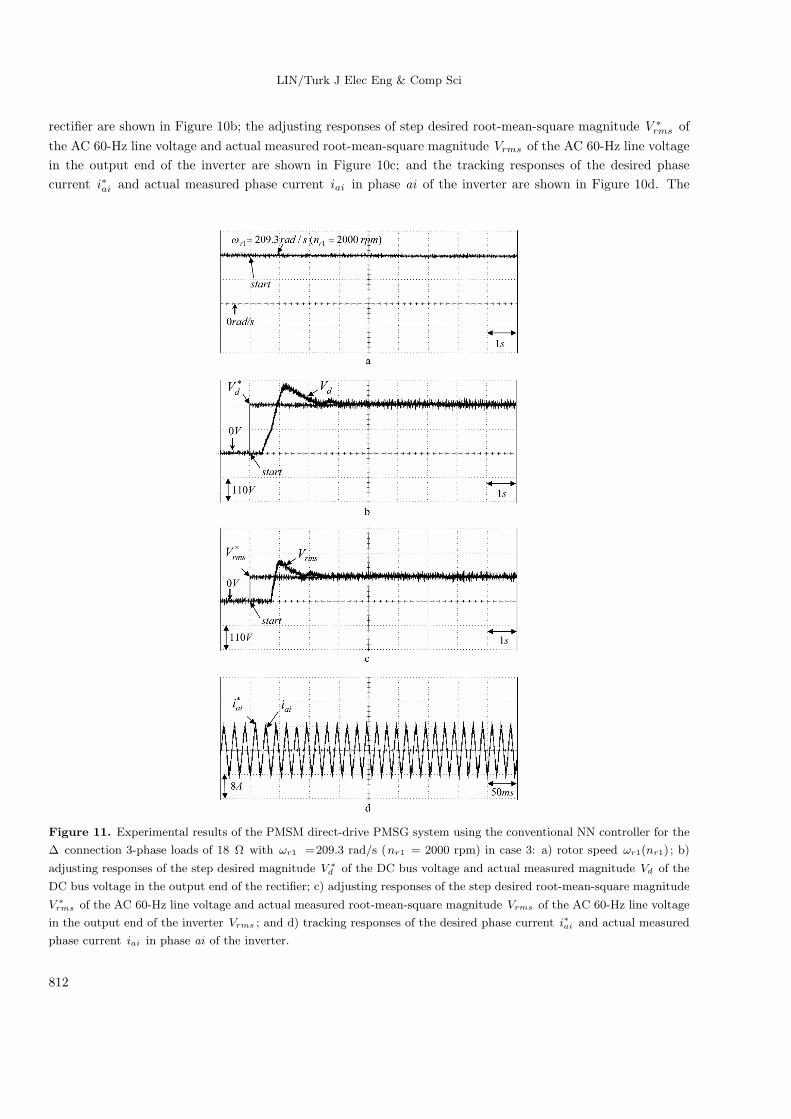
experimental results of the PMSM direct-drive PMSG system using the conventional NN controller for the ∆
connection 3-phase loads of 18 Ω with ωr1 = 209.3 rad/s (nr1 = 2000 rpm) in case 3 are shown in Figure 11,
where the rotor speed ωr1(nr1) is shown in Figure 11a; the adjusting responses of the step desired magnitude
V ∗d of the DC bus voltage and actual measured magnitude Vd of the DC bus voltage in the output end of
the rectifier are shown in Figure 11b; the adjusting responses of the step desired root-mean-square magnitude
V ∗rms of the AC 60-Hz line voltage and actual measured root-mean-square magnitude Vrms of the AC 60-Hz
line voltage in the output end of the inverter are shown in Figure 11c; and the tracking responses of the desired
phase current i∗ai and actual measured phase current iai in phase ai of the inverter are shown in Figure 11d.
From the experimental results, a few sluggish DC bus voltage and AC 60-Hz line voltage adjusting responses are
obtained for the PI-controlled PMSM direct-drive PMSG system because of the weak robustness of the linear
controller.
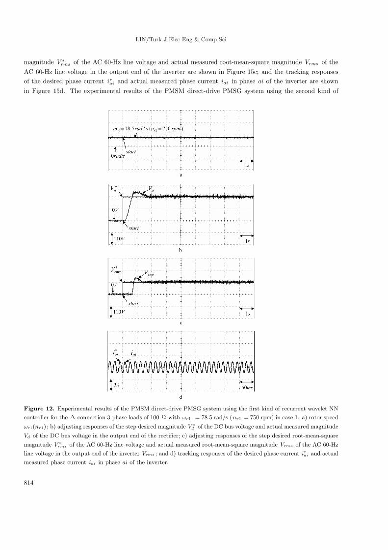
Some experimental results of the proposed recurrent wavelet NN-controlled PMSM direct-drive PMSG
system are discussed. The experimental results of the PMSM direct-drive PMSG system using the first kind of
recurrent wavelet NN controller for the ∆ connection 3-phase loads of 100 Ω with ωr1 = 78.5 rad/s (nr1 =
750 rpm) in case 1 are shown in Figure 12, where the rotor speed ωr1(nr1) is shown in Figure 12a; the adjusting
responses of the step desired magnitude V ∗d of the DC bus voltage and actual measured magnitude Vd of the
DC bus voltage in the output end of the rectifier are shown in Figure 12b; the adjusting responses of the step
desired root-mean-square magnitude V ∗rms of the AC 60-Hz line voltage and actual measured root-mean-square
magnitude Vrms of the AC 60-Hz line voltage in the output end of the inverter are shown in Figure 12c; and
the tracking responses of the desired phase current i∗ai and actual measured phase current iai in phase ai
of the inverter are shown in Figure 12d. The experimental results of the PMSM direct-drive PMSG system
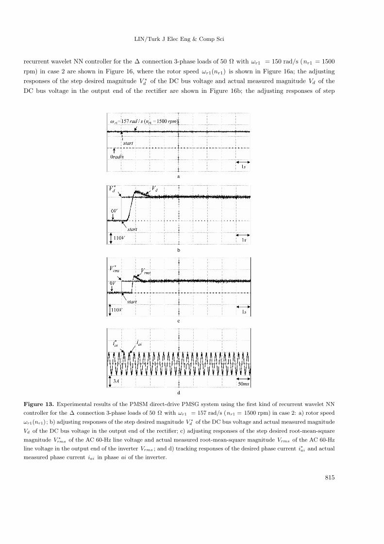
using the first kind of recurrent wavelet NN controller for the ∆ connection 3-phase loads of 50 Ω with ωr1
= 150 rad/s (nr1 = 1500 rpm) in case 2 are shown in Figure 13, where the rotor speed ωr1(nr1) is shown
in Figure 13a; the adjusting responses of the step desired magnitude V ∗d of the DC bus voltage and actual
measured magnitude Vd of the DC bus voltage in the output end of the rectifier are shown in Figure 13b;
the adjusting responses of the step desired root-mean-square magnitude V ∗rms of the AC 60-Hz line voltage
and actual measured root-mean-square magnitude Vrms of the AC 60-Hz line voltage in the output end of
the inverter are shown in Figure 13c; and the tracking responses of the desired phase current i∗ai and actual
measured phase current iai in phase ai of the inverter are shown in Figure 13d. The experimental results of the
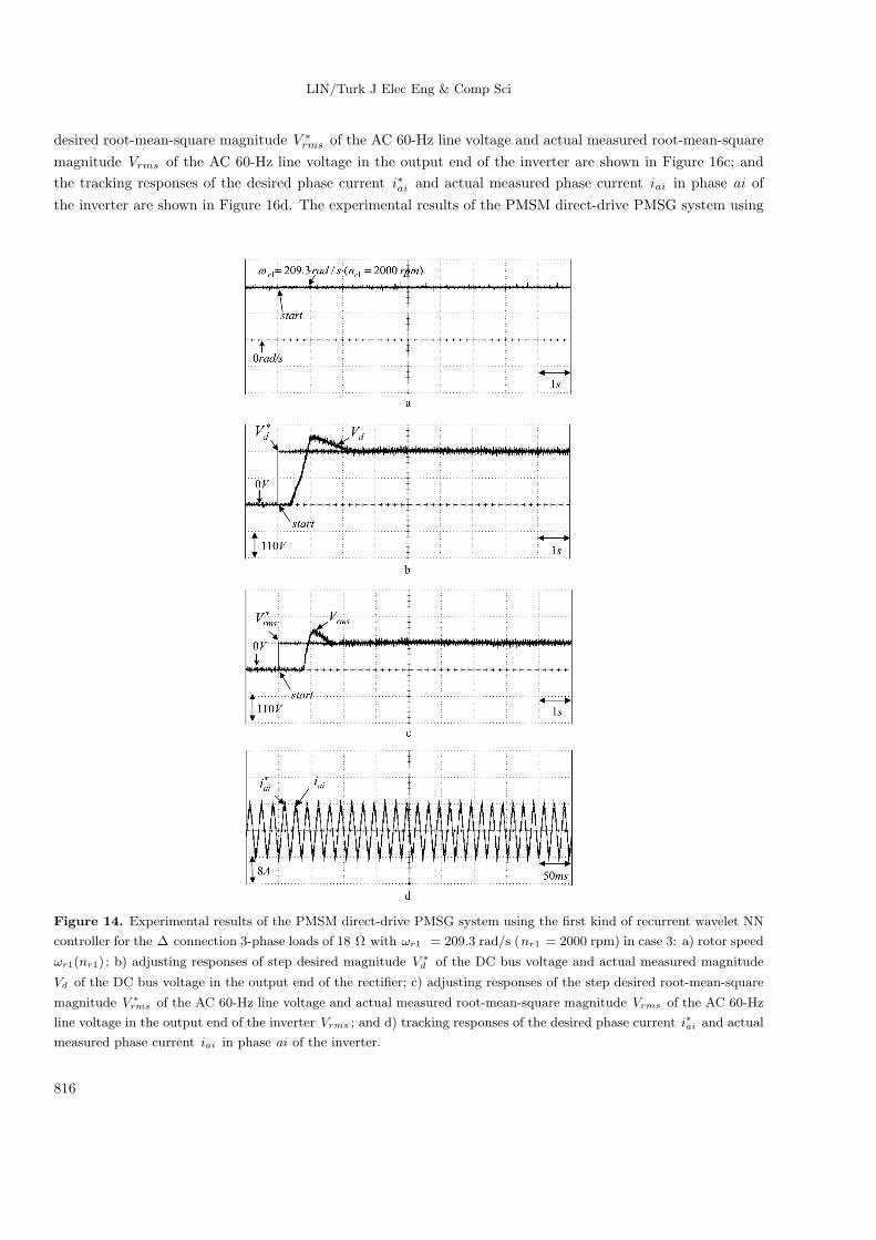
PMSM direct-drive PMSG system using the first kind of recurrent wavelet NN controller for the ∆ connection
3-phase loads of 18 Ω with ωr1 = 209.3 rad/s (nr1 = 2000 rpm) in case 3 are shown in Figure 14, where the
rotor speed ωr1(nr1) is shown in Figure 14a; the adjusting responses of the step desired magnitude V ∗d of the
DC bus voltage and actual measured magnitude Vd of the DC bus voltage in the output end of the rectifier
are shown in Figure 14b; the adjusting responses of the step desired root-mean-square magnitude V ∗rms of the
AC 60-Hz line voltage and actual measured root-mean-square magnitude Vrms of the AC 60-Hz line voltage
in the output end of the inverter are shown in Figure 14c; and the tracking responses of the desired phase
current i∗ai and actual measured phase current iai in phase ai of the inverter are shown in Figure 14d. The
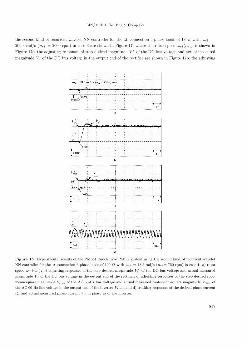
experimental results of the PMSM direct-drive PMSG system using the second kind of recurrent wavelet NN
controller for the ∆ connection 3-phase loads of 100 Ω with ωr1 = 78.5 rad/s (nr1 = 750 rpm) in case 1 are
shown in Figure 15, where the rotor speed ωr1(nr1) is shown in Figure 15a; the adjusting responses of the step
desired magnitude V ∗d of the DC bus voltage and actual measured magnitude Vd of the DC bus voltage in the
output end of the rectifier are shown in Figure 15b; the adjusting responses of the step desired root-mean-square
813
LIN/Turk J Elec Eng & Comp Sci
magnitude V ∗rms of the AC 60-Hz line voltage and actual measured root-mean-square magnitude Vrms of the
AC 60-Hz line voltage in the output end of the inverter are shown in Figure 15c; and the tracking responses
of the desired phase current i∗ai and actual measured phase current iai in phase ai of the inverter are shown
in Figure 15d. The experimental results of the PMSM direct-drive PMSG system using the second kind of
Figure 12. Experimental results of the PMSM direct-drive PMSG system using the first kind of recurrent wavelet NN
controller for the ∆ connection 3-phase loads of 100 Ω with ωr1 = 78.5 rad/s (nr1 = 750 rpm) in case 1: a) rotor speed
ωr1(nr1) ; b) adjusting responses of the step desired magnitude V ∗d of the DC bus voltage and actual measured magnitude
Vd of the DC bus voltage in the output end of the rectifier; c) adjusting responses of the step desired root-mean-square
magnitude V ∗rms of the AC 60-Hz line voltage and actual measured root-mean-square magnitude Vrms of the AC 60-Hz
line voltage in the output end of the inverter Vrms ; and d) tracking responses of the desired phase current i∗ai and actual
measured phase current iai in phase ai of the inverter.
814
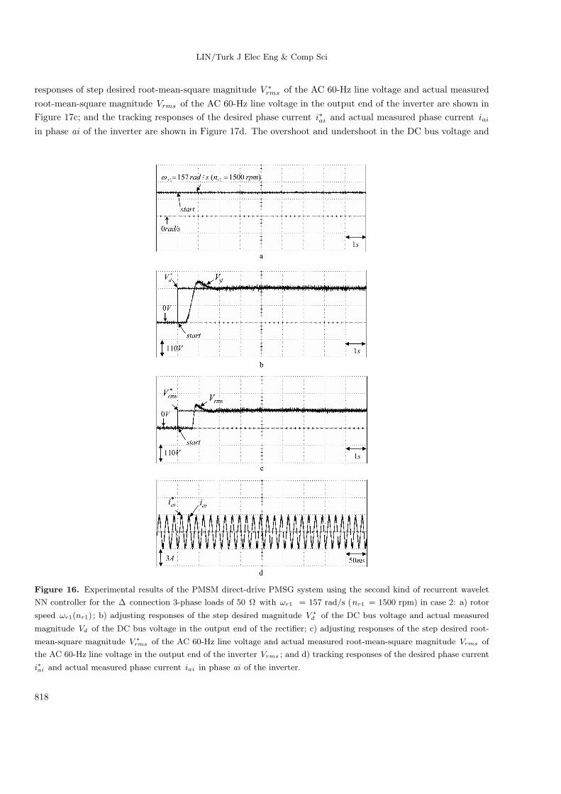
LIN/Turk J Elec Eng & Comp Sci
recurrent wavelet NN controller for the ∆ connection 3-phase loads of 50 Ω with ωr1 = 150 rad/s (nr1 = 1500
rpm) in case 2 are shown in Figure 16, where the rotor speed ωr1(nr1) is shown in Figure 16a; the adjusting
responses of the step desired magnitude V ∗d of the DC bus voltage and actual measured magnitude Vd of the
DC bus voltage in the output end of the rectifier are shown in Figure 16b; the adjusting responses of step
Figure 13. Experimental results of the PMSM direct-drive PMSG system using the first kind of recurrent wavelet NN
controller for the ∆ connection 3-phase loads of 50 Ω with ωr1 = 157 rad/s (nr1 = 1500 rpm) in case 2: a) rotor speed
ωr1(nr1) ; b) adjusting responses of the step desired magnitude V ∗d of the DC bus voltage and actual measured magnitude
Vd of the DC bus voltage in the output end of the rectifier; c) adjusting responses of the step desired root-mean-square
magnitude V ∗rms of the AC 60-Hz line voltage and actual measured root-mean-square magnitude Vrms of the AC 60-Hz
line voltage in the output end of the inverter Vrms ; and d) tracking responses of the desired phase current i∗ai and actual
measured phase current iai in phase ai of the inverter.
815
LIN/Turk J Elec Eng & Comp Sci
desired root-mean-square magnitude V ∗rms of the AC 60-Hz line voltage and actual measured root-mean-square
magnitude Vrms of the AC 60-Hz line voltage in the output end of the inverter are shown in Figure 16c; and
the tracking responses of the desired phase current i∗ai and actual measured phase current iai in phase ai of
the inverter are shown in Figure 16d. The experimental results of the PMSM direct-drive PMSG system using
Figure 14. Experimental results of the PMSM direct-drive PMSG system using the first kind of recurrent wavelet NN
controller for the ∆ connection 3-phase loads of 18 Ω with ωr1 = 209.3 rad/s (nr1 = 2000 rpm) in case 3: a) rotor speed
ωr1(nr1) ; b) adjusting responses of step desired magnitude V ∗d of the DC bus voltage and actual measured magnitude
Vd of the DC bus voltage in the output end of the rectifier; c) adjusting responses of the step desired root-mean-square
magnitude V ∗rms of the AC 60-Hz line voltage and actual measured root-mean-square magnitude Vrms of the AC 60-Hz
line voltage in the output end of the inverter Vrms ; and d) tracking responses of the desired phase current i∗ai and actual
measured phase current iai in phase ai of the inverter.
816
LIN/Turk J Elec Eng & Comp Sci
the second kind of recurrent wavelet NN controller for the ∆ connection 3-phase loads of 18 Ω with ωr1 =
209.3 rad/s (nr1 = 2000 rpm) in case 3 are shown in Figure 17, where the rotor speed ωr1(nr1) is shown in
Figure 17a; the adjusting responses of step desired magnitude V ∗d of the DC bus voltage and actual measured
magnitude Vd of the DC bus voltage in the output end of the rectifier are shown in Figure 17b; the adjusting
Figure 15. Experimental results of the PMSM direct-drive PMSG system using the second kind of recurrent wavelet
NN controller for the ∆ connection 3-phase loads of 100 Ω with ωr1 = 78.5 rad/s (nr1= 750 rpm) in case 1: a) rotor
speed ωr1(nr1) ; b) adjusting responses of the step desired magnitude V ∗d of the DC bus voltage and actual measured
magnitude Vd of the DC bus voltage in the output end of the rectifier; c) adjusting responses of the step desired root-
mean-square magnitude V ∗rms of the AC 60-Hz line voltage and actual measured root-mean-square magnitude Vrms of
the AC 60-Hz line voltage in the output end of the inverter Vrms ; and d) tracking responses of the desired phase current
i∗ai and actual measured phase current iai in phase ai of the inverter.
817
LIN/Turk J Elec Eng & Comp Sci
responses of step desired root-mean-square magnitude V ∗rms of the AC 60-Hz line voltage and actual measured
root-mean-square magnitude Vrms of the AC 60-Hz line voltage in the output end of the inverter are shown in
Figure 17c; and the tracking responses of the desired phase current i∗ai and actual measured phase current iai
in phase ai of the inverter are shown in Figure 17d. The overshoot and undershoot in the DC bus voltage and
Figure 16. Experimental results of the PMSM direct-drive PMSG system using the second kind of recurrent wavelet
NN controller for the ∆ connection 3-phase loads of 50 Ω with ωr1 = 157 rad/s (nr1 = 1500 rpm) in case 2: a) rotor
speed ωr1(nr1) ; b) adjusting responses of the step desired magnitude V ∗d of the DC bus voltage and actual measured
magnitude Vd of the DC bus voltage in the output end of the rectifier; c) adjusting responses of the step desired root-
mean-square magnitude V ∗rms of the AC 60-Hz line voltage and actual measured root-mean-square magnitude Vrms of
the AC 60-Hz line voltage in the output end of the inverter Vrms ; and d) tracking responses of the desired phase current
i∗ai and actual measured phase current iai in phase ai of the inverter.
818
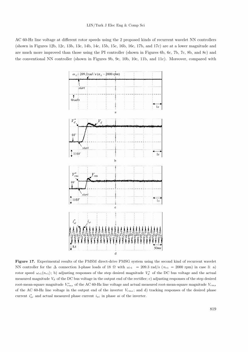
LIN/Turk J Elec Eng & Comp Sci
AC 60-Hz line voltage at different rotor speeds using the 2 proposed kinds of recurrent wavelet NN controllers
(shown in Figures 12b, 12c, 13b, 13c, 14b, 14c, 15b, 15c, 16b, 16c, 17b, and 17c) are at a lower magnitude and
are much more improved than those using the PI controller (shown in Figures 6b, 6c, 7b, 7c, 8b, and 8c) and
the conventional NN controller (shown in Figures 9b, 9c, 10b, 10c, 11b, and 11c). Moreover, compared with
Figure 17. Experimental results of the PMSM direct-drive PMSG system using the second kind of recurrent wavelet
NN controller for the ∆ connection 3-phase loads of 18 Ω with ωr1 = 209.3 rad/s (nr1 = 2000 rpm) in case 3: a)
rotor speed ωr1(nr1) ; b) adjusting responses of the step desired magnitude V ∗d of the DC bus voltage and the actual
measured magnitude Vd of the DC bus voltage in the output end of the rectifier; c) adjusting responses of the step desired
root-mean-square magnitude V ∗rms of the AC 60-Hz line voltage and actual measured root-mean-square magnitude Vrms
of the AC 60-Hz line voltage in the output end of the inverter Vrms ; and d) tracking responses of the desired phase
current i∗ai and actual measured phase current iai in phase ai of the inverter.
819

LIN/Turk J Elec Eng & Comp Sci
the PI control method and the conventional NN control, the proposed recurrent wavelet NN control method
improves the tracking ability and reduces the oscillations in steady-state.
5. Conclusions
This study demonstrates the implementation of both the DC bus voltage and AC 60-Hz line voltage adjustment
of a PMSG system direct-driven by a PMSM based on a wind turbine emulator, using 2 sets of the same recurrent
wavelet NN controllers for stand-alone power applications. First, the field-oriented control is implemented for
the control of the PMSG system direct-driven by a PMSM based on a wind turbine emulator. Next, 2 sets of
the same recurrent wavelet NN controllers are proposed to adjust the DC bus voltage of the rectifier and the
AC 60-Hz line voltage of the inverter. In addition, the control performance of the proposed recurrent wavelet
NN-controlled PMSM direct-drive PMSG system is robust with regard to the 2 operating conditions of the
PMSG. Because of the weak robustness of the linear controller for the PI-controlled PMSM direct-drive PMSGsystem, dull DC bus voltage and AC 60-Hz line voltage adjusting responses are obviously obtained from the
experimental results. The important contribution of this study is the successful application of the 2 sets of the
same recurrent wavelet NN controllers on the PMSM direct-drive PMSG system to adjust the DC bus voltage of
the rectifier and the AC 60-Hz line voltage of the inverter with robust control performance. Finally, the control
performance of the proposed recurrent wavelet NN controller shown in the experimental results is superior to
the PI controller and conventional NN controller for the PMSG system direct-driven by a PMSM based on a
wind turbine emulator with a rectifier and an inverter for stand-alone power applications. The system of the
proposed control scheme will extend to be applied for the grid system of electric utilities with battery energy
storage due to the raised reliability of the system in the future.
Acknowledgments
The author would like to acknowledge the financial support of the National Science Council of Taiwan, R.O.C.,
through grant NSC 99-2221-E-239-040-MY3.
Nomenclature
vd1, vq1 d and q axis stator voltages of the permanent magnet synchronous generator(PMSG)
id1, iq1 d and q axis stator currents of the PMSG
Ld1, Lq1 d and q axis inductances of the PMSG
Rs1 Phase winding resistance of the PMSG
ωr1, nr1 Rotor angular velocity of the PMSG in rad/s, in rpm
λpm Permanent magnet mutual flux linkage of the PMSG
P Number of poles of the PMSG
β Tip ratio of the wind turbine
R1 Turbine rotor radius of the wind turbine
T1 Output torque of the wind turbine
Te Electromagnetic torque of the PMSG
J1 Moment of inertia of the PMSG
B1 Viscous friction coefficient of the PMSG
ρ1 Density of the air
Kt Torque constant of the PMSG
820
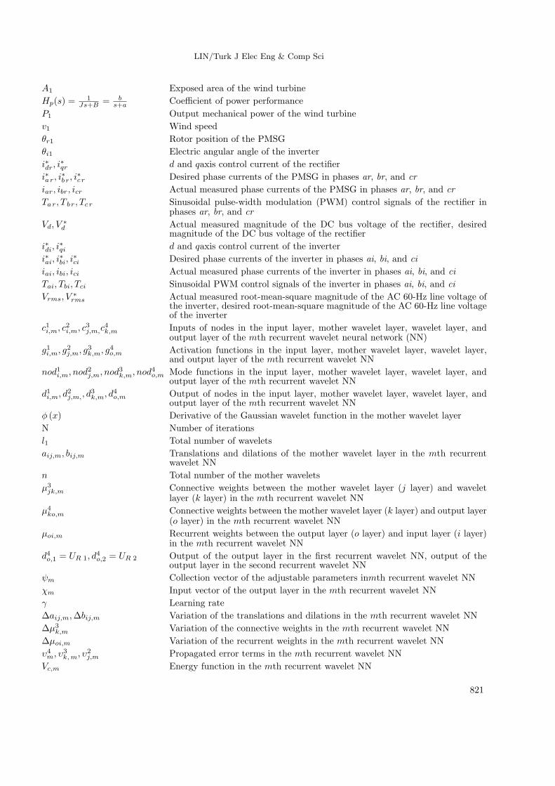
LIN/Turk J Elec Eng & Comp Sci
A1 Exposed area of the wind turbine
Hp(s) =1
Js+B = bs+a Coefficient of power performance
P1 Output mechanical power of the wind turbine
v1 Wind speed
θr1 Rotor position of the PMSG
θi1 Electric angular angle of the inverter
i∗dr, i∗qr d and qaxis control current of the rectifier
i∗ar, i∗br, i
∗cr Desired phase currents of the PMSG in phases ar, br, and cr
iar, ibr, icr Actual measured phase currents of the PMSG in phases ar, br, and cr
Tar, Tbr, Tcr Sinusoidal pulse-width modulation (PWM) control signals of the rectifier inphases ar, br, and cr
Vd, V∗d Actual measured magnitude of the DC bus voltage of the rectifier, desired
magnitude of the DC bus voltage of the rectifier
i∗di, i∗qi d and qaxis control current of the inverter
i∗ai, i∗bi, i
∗ci Desired phase currents of the inverter in phases ai, bi, and ci
iai, ibi, ici Actual measured phase currents of the inverter in phases ai, bi, and ci
Tai, Tbi, Tci Sinusoidal PWM control signals of the inverter in phases ai, bi, and ci
Vrms, V∗rms Actual measured root-mean-square magnitude of the AC 60-Hz line voltage of
the inverter, desired root-mean-square magnitude of the AC 60-Hz line voltageof the inverter
c1i,m, c2i,m, c
3j,m,c
4k,m Inputs of nodes in the input layer, mother wavelet layer, wavelet layer, and
output layer of the mth recurrent wavelet neural network (NN)
g1i,m, g2j,m, g
3k,m, g
4o,m Activation functions in the input layer, mother wavelet layer, wavelet layer,
and output layer of the mth recurrent wavelet NN
nod1i,m, nod2j,m, nod
3k,m, nod
4o,m Mode functions in the input layer, mother wavelet layer, wavelet layer, and
output layer of the mth recurrent wavelet NN
d1i,m, d2j,m,, d
3k,m, d
4o,m Output of nodes in the input layer, mother wavelet layer, wavelet layer, and
output layer of the mth recurrent wavelet NN
ϕ (x) Derivative of the Gaussian wavelet function in the mother wavelet layer
N Number of iterations
l1 Total number of wavelets
aij,m, bij,m Translations and dilations of the mother wavelet layer in the mth recurrentwavelet NN
n Total number of the mother wavelets
µ3jk,m Connective weights between the mother wavelet layer (j layer) and wavelet
layer (k layer) in the mth recurrent wavelet NN
µ4ko,m Connective weights between the mother wavelet layer (k layer) and output layer
(o layer) in the mth recurrent wavelet NN
µoi,m Recurrent weights between the output layer (o layer) and input layer (i layer)in the mth recurrent wavelet NN
d4o,1 = UR 1, d4o,2 = UR 2 Output of the output layer in the first recurrent wavelet NN, output of the
output layer in the second recurrent wavelet NN
ψm Collection vector of the adjustable parameters inmth recurrent wavelet NN
χm Input vector of the output layer in the mth recurrent wavelet NN
γ Learning rate
∆aij,m,∆bij,m Variation of the translations and dilations in the mth recurrent wavelet NN
∆µ3k,m Variation of the connective weights in the mth recurrent wavelet NN
∆µoi,m Variation of the recurrent weights in the mth recurrent wavelet NN
υ4m, υ3k,m, υ
2j,m Propagated error terms in the mth recurrent wavelet NN
Vc,m Energy function in the mth recurrent wavelet NN
821
LIN/Turk J Elec Eng & Comp Sci
References
[1] K. Tan, S. Islam, “Optimum control strategies in energy conversion of PMSG wind turbine system without
mechanical sensors”, IEEE Transactions on Energy Conversion, Vol. 19, pp. 392–400, 2004.
[2] M. Kolhe, J.C. Joshi, D.P. Kothari, “Performance analysis of a directly coupled photovoltaic water-pumping
system”, IEEE Transactions on Energy Conversion, Vol. 19, pp. 613–618, 2004.
[3] G.K. Andersen, C. Klumpner, S.B. Kjaer, F. Blaabjerg, “A new green power inverter for fuel cells”, Proceedings of
the IEEE 33rd Annual Power Electronics Specialists Conference, pp. 727–733, 2002.
[4] Z. Lubosny, Wind Turbine Operation in Electric Power Systems, Berlin, Springer, 2003.
[5] T. Ackermann, Wind Power in Power Systems, New York, Wiley, 2005.
[6] M. Karrari, W. Rosehart, O.P. Malik, “Comprehensive control strategy for a variable speed cage machine wind
generation unit”, IEEE Transactions on Energy Conversion, Vol. 20, pp. 415–423, 2005.
[7] I. Boldea, Synchronous Generators, Boca Raton, FL, USA, Taylor and Francis, 2006.
[8] M. Chinchilla, S. Arnaltes, I.C. Burgos, “Control of permanent magnet generators applied to variable-speed wind-
energy systems connected to the grid”, IEEE Transactions on Energy Conversion, Vol. 21, pp. 130–135, 2006.
[9] S. Sajedi, F. Kahlifeh, T. Karimi, Z. Khalifeh, “Maximum power point tracking of variable speed wind energy
conversion system”, International Journal of Physical Sciences, Vol. 6, pp. 6843–6851, 2011.
[10] F. Gharedaghi, H. Jamali, M. Deysi, A Khalili, “Maximum power point tracking of variable speed wind generation
system connected to permanent magnet synchronous generator”, International Review of Electrical Engineering,
Vol. 4, pp. 1044–1049, 2011.
[11] B. Delyon, A. Juditsky, A. Benveniste, “Accuracy analysis for wavelet approximations”, IEEE Transactions on
Neural Networks, Vol. 6, pp. 332–348, 1995.
[12] C.F. Chen, C.H. Hsiao, “Wavelet approach to optimizing dynamic systems”, IEE Proceedings – Control Theory
and Applications, Vol. 146, pp. 213–219, 1999.
[13] Q. Zhang, A. Benveniste, “Wavelet networks”, IEEE Transactions on Neural Networks, Vol. 3, pp. 889–898, 1992.
[14] J. Zhang, G.G. Walter, Y. Miao, W.N.W. Lee, “Wavelet neural networks for function learning”, IEEE Transactions
on Signal Processing, Vol. 43, pp. 1485–1496, 1995.
[15] Z. Zhang, C. Zhao, “A fast learning algorithm for wavelet network and its application in control”, Proceedings of
IEEE International Conference on Control Automation, pp. 1403–1407, 2007.
[16] H.L. Wei, S.A. Billings, “A unified wavelet-based modelling framework for nonlinear system identification: the
WANARX model structure”, International Journal of Control, Vol. 77, pp. 351–366, 2004.
[17] H.L. Wei, S.A. Billings, M.A. Balikhin, “Wavelet based nonparametric NARX models for nonlinear input-output
system identification”, International Journal of Systems Science, Vol. 37, pp. 1089–1096, 2006.
[18] M. Ravan, R.K. Amineh, M. Karrari, W.B. Rosehart, O.P. Malik, “Synchronous machine model identification using
continuous wavelet NARX network”, Proceedings of the Institution of Mechanical Engineers – Part I: Journal of
Systems and Control Engineering, Vol. 223, pp. 467–477, 2009.
[19] J. Xu, D.W.C. Ho, D. Zhou, “Adaptive wavelet networks for nonlinear system identification”, Proceedings of the
American Control Conference, pp. 3472–3473, 1997.
[20] N. Sureshbabu, J.A. Farrell, “Wavelet-based system identification for nonlinear control”, IEEE Transactions on
Automatic Control, Vol. 44, pp. 412–417, 1999.
[21] S.A. Billings, H.L. Wei, “A new class of wavelet networks for nonlinear system identification”, IEEE Transactions
on Neural Networks, Vol. 16, pp. 862–874, 2005.
[22] R.H. Abiyev, O.Kaynak, “Fuzzy wavelet neural networks for identification and control of dynamic plants—a novel
structure and a comparative study”, IEEE Transactions on Industrial Electronics, Vol. 55, pp. 3133–3140, 2008.
822
LIN/Turk J Elec Eng & Comp Sci
[23] D. Giaouris, J.W. Finch, O.C. Ferreira, R.M. Kennel, G.M. El-Murr, “Wavelet denoising for electric drives”, IEEE
Transactions on Industrial Electronics, Vol. 55, pp. 543–550, 2008.
[24] D. Gonzalez, J.T. Bialasiewicz, J. Balcells, J. Gago, “Wavelet-based performance evaluation of power converters
operating with modulated switching frequency”, IEEE Transactions on Industrial Electronics, Vol. 55, pp. 3167–
3176, 2008.
[25] F.J. Lin, R.J. Wai, M.P. Chen, “Wavelet neural network control for linear ultrasonic motor drive via adaptive
sliding-mode technique”, IEEE Transactions on Ultrasonics, Ferroelectrics, and Frequency Control, Vol. 50, pp.
686–697, 2003.
[26] G. Gokmen, “Wavelet based instantaneous reactive power calculation method and a power system application
sample”, International Review of Electrical Engineering, Vol. 4, pp. 745–752, 2011.
[27] S.H. Ling, H.H.C. Iu, F.H.F. Leung, K.Y. Chan, “Improved hybrid particle swarm optimized wavelet neural
network for modeling the development of fluid dispensing for electronic packaging”, IEEE Transactions on Industrial
Electronics, Vol. 55, pp. 3447–3460, 2008.
[28] S. Partal, I. Senol, A.F. Bakan, K.N. Bekiroglu, “Online speed control of a brushless AC servomotor based on
artificial neural networks”, Turkish Journal of Electrical Engineering & Computer Sciences, Vol. 19, pp. 373–383,
2011.
[29] A.T. Ozdemir, K. Danısman, “Fully parallel ANN-based arrhythmia classifier on a single-chip FPGA: FPAAC”,
Turkish Journal of Electrical Engineering & Computer Sciences, Vol. 19, pp. 667–687, 2011.
[30] A.A. Kulaksız, R. Akkaya, “Training data optimization for ANNs using genetic algorithms to enhance MPPT
efficiency of a stand-alone PV system”, Turkish Journal of Electrical Engineering & Computer Sciences, Vol. 20,
pp. 241–254, 2012.
[31] M. Moazzami, R.A. Hooshmand, “Short-term nodal congestion price forecasting in a large-scale power market using
ANN with genetic optimization training”, Turkish Journal of Electrical Engineering & Computer Sciences, Vol. 20,
pp. 751–768, 2012.
[32] H. Bouzari, H. Moradi, E. Bouzari, “Adaptive neuro-wavelet system for the robust control of switching power
supplies”, IEEE International Multitopic Conference, pp. 1–6, 2008.
[33] K. Funahashi, Y. Nakamura, “Approximation of dynamical systems by continuous time recurrent neural network”,
Neural Networks, Vol. 6, pp. 801–806, 1993.
[34] L. Jin, P.N. Nikiforuk, M. Gupta, “Approximation of discrete-time state-space trajectories using dynamic recurrent
networks”, IEEE Transactions on Automatic Control, Vol. 6. pp. 1266–1270, 1995.
[35] C.C. Ku, K.Y. Lee, “Diagonal recurrent neural networks for dynamical system control”, IEEE Transactions on
Neural Networks, Vol. 6, pp. 144–156, 1995.
[36] C.H. Lu, C.C. Tsai, “Adaptive predictive control with recurrent neural network for industrial processes: an
application to temperature control of a variable-frequency oil-cooling machine”, IEEE Transactions on Industrial
Electronics, Vol. 55, pp. 1366–1375, 2008.
[37] P. Brandstetter, M. Kuchar, I. Neborak, “Selected applications of artificial neural networks in the control of AC
induction motor drives”, International Review of Electrical Engineering, Vol. 4, pp. 1084–1093, 2011.
[38] M. Ghariani, I.B. Salah, M. Ayadi, R. Neji, “Neural induction machine observer for electric vehicle applications”,
International Review of Electrical Engineering, Vol. 3, pp. 314–324, 2010.
[39] S.J. Yoo, J.B. Park, Y.H. Choi, “Stable predictive control of chaotic systems using self-recurrent wavelet neural
network”, International Journal of Automatic Control Systems, Vol. 3, pp. 43–55, 2005.
[40] S.J. Yoo, Y.H. Choi, J.B. Park, “Generalized predictive control based on self-recurrent wavelet neural network
for stable path tracking of mobile robots: adaptive learning rates approach”, IEEE Transactions on Circuits and
Systems I, Vol. 53, pp. 1381–1394, 2006.
823

LIN/Turk J Elec Eng & Comp Sci
[41] C.H. Lu, “Design and application of stable predictive controller using recurrent wavelet neural networks”, IEEE
Transactions on Industrial Electronics, Vol. 56, pp. 3733–3742, 2009.
[42] C.H. Chen, C.F. Hsu, “Recurrent wavelet neural backstepping controller design with a smooth compensator”, Neural
Computation and Applications, Vol. 19, pp. 1089–1100, 2010.
[43] S.I. Han, J.M. Lee, “Adaptive dynamic surface control with sliding mode control and RWNN for robust positioning
of a linear motion stage”, Mechatronics, Vol. 22, pp. 222–238, 2012.
[44] F.J. Lin , L.T. Teng, M.H. Yu, “Radial basis function network control with improved particle swarm optimization
for induction generator system”, IEEE Transactions on Power Electronics, Vol. 23, pp. 2157–2169, 2008.
[45] Y. Oussar, G. Dreyfus, “Initialization by selection for wavelet network training”, Neurocomputing, Vol. 34, pp.
131–143, 2000.
824