Rectifier O and M Manual _ Nuberg - Fluoder
59
User’s Manual RECTIFIER Maintenance and Troubleshooting ABB INDIA Ltd Dept. DM – PC NEELAMANGAL/BANGALORE
description
Rectifier O and M Manual _ Nuberg - Fluoder
Transcript of Rectifier O and M Manual _ Nuberg - Fluoder

User’s Manual
RECTIFIER
Maintenance and Troubleshooting
ABB INDIA LtdDept. DM – PC
NEELAMANGAL/BANGALORE

Contents
Page
1 Safety Instructions
1.1 Safety Instruction for Troubleshooting 5 1.2 Safety Instruction for Functional Checks 6
1.3 Safety Instruction for Converter Inspection 7 1.4 Safety instruction for Inspection, Maintenance and Repair 7 1.5 Safety Instruction for Replacement of items 9
2 Alarms and Trips Handling 10
Title Plant Description Project NUBERG_FLUODER, South AmericaPre. SMD DM-PCAppr. CVP DM-PC
Document identity 3AYN122174-MAD Lang. Rev. ind. Page 1
ABB INDIA Ltd E - No. ofpages 60

Safety Instructions
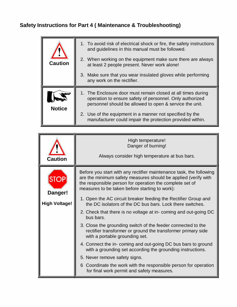
Safety Instructions for Part 4 ( Maintenance & Troubleshooting)
Caution
1. To avoid risk of electrical shock or fire, the safety instructionsand guidelines in this manual must be followed.
2. When working on the equipment make sure there are alwaysat least 2 people present. Never work alone!
3. Make sure that you wear insulated gloves while performingany work on the rectifier.
Notice
1. The Enclosure door must remain closed at all times duringoperation to ensure safety of personnel. Only authorizedpersonnel should be allowed to open & service the unit.
2. Use of the equipment in a manner not specified by themanufacturer could impair the protection provided within.
Caution
High temperature!Danger of burning!
Always consider high temperature at bus bars.
Danger!
High Voltage!
Before you start with any rectifier maintenance task, the followingare the minimum safety measures should be applied (verify withthe responsible person for operation the complete set ofmeasures to be taken before starting to work):
1. Open the AC circuit breaker feeding the Rectifier Group andthe DC isolators of the DC bus bars. Lock there switches.
2. Check that there is no voltage at in- coming and out-going DCbus bars.
3. Close the grounding switch of the feeder connected to therectifier transformer or ground the transformer primary sidewith a portable grounding set.
4. Connect the in- coming and out-going DC bus bars to groundwith a grounding set according the grounding instructions.
5. Never remove safety signs.
6 Coordinate the work with the responsible person for operation for final work permit and safety measures.

1.1 Safety Instructions for Trouble Shooting
Danger!
Never operate the Rectifier Equipment with the rectifier enclosuredoors open.
Danger!High Voltage!
After a trip of one unit, the remaining units could possibly remainenergized. This means that the load side of the DC Isolators couldalso be energized. Before doing any maintenance on the DCIsolators, ensure that the other units have been switched off! Checkif there is no voltage on any of the DC busbars concerned.
Danger!AuxiliaryVoltage!
There may be an external auxiliary voltage present even if youdisconnect the system from the main power supply. Check this!
Caution
Static discharge can damage electronic parts
Always wear the anti-static protection strap before you handleany PCB's. The anti-static protection strap is part of the deliveryand can be found at the PCB rack door.

Caution
ElectricShocksBurningHazard
· Do not enter while energised.· Refer to user’s manual & Circuit diagrams before starting
with the service.
· Part of this equipment may be energised or controlledfrom multiple sources.
NoticeAlways check the description of the Alarms and Trips in theUser’s Manual Part 4 “Maintenance and Trouble Shooting”.
1.2 Safety Instructions for Functional checks
Notice
Every printed circuit board (PCB) has a fault dedection andindication system (red LED on: fault / green LED on: workingproperly (optional). set to REMOTE control.
Stop!!
High Voltage! Danger!
Follow all safety instructions before you start any functionalcheck.
Notice For remote control, the Mode Control switch on the local controlpanel must be set to REMOTE (control).
Notice Do the inspection work that is mentioned in Part 4, Maintenanceand Trouble Shooting, monthly, if possible.

1.3 Remark for Converter Inspection
NoticeGreasy dust, metallic particles and humidity/moisture coulddamage the converter! Protect the equipment from adverseenvironmental conditions.
1.4 Safety Instructions for Inspection, Maintenance and Repair
Danger!
HighVoltage!
Before starting commissioning and maintenance work, the unit hasto be grounded according to the following description:
1. Open main circuit breaker2. Open DC Isolators3. Lock the circuit breaker4. Close grounding switch5. Measure AC and DC Voltage at the Rectifier (must be zero)6. Connect the grounding equipment to the transformer
secondary bushings
All national, local and proprietary safety instructions have tobe followed!
Caution
High!
Temperature! Danger of burning!
Consider high temperature at bus bars, reactors and heaters.
Caution
Static discharge can damage electronic parts
Always wear the anti-static protection strap before you touch anyPCB's. The anti-static protection strap is part of the delivery andcan be found at the PCB rack door.

Caution
You could be injured if you try to perform trouble shooting workon the Rectifier Equipment without sufficient knowledge. Be sureyou have the knowledge, experience, and the properreplacement parts and tools before you attempt any troubleshooting
Danger!High Voltage!
After a trip of one unit, the remaining units could possibly remainenergized. This means that the load side of the DC Isolatorscould also be energized. Check if there is no voltage on any ofthe DC busbars concerned!
Notice
If you try to perform trouble shooting work on the RectifierEquipment without sufficient knowledge, the converter unit couldbe damaged. Be sure you have sufficient knowledge, experience,and the proper replacement parts and tools before you attemptany trouble shooting
Notice
Do not install any replacement part in the Rectifier Equipmentunless you first check with the recommended spare parts list (seePart 4, Maintenance and Trouble Shooting) or with ABB forcorrectness. Some can damage the converter. Your warrantywould not cover that. Some may disturbe proper operation.

1.5 Safety Instructions for Replacement of Items
Danger!AuxiliaryVoltage!
There may be auxiliary voltage present even if you disconnectthe system from the main power supply.
Caution
High temperature!Danger of burning!
Always consider high temperature at bus bars, reactors andheaters.
Caution
Use centering pin ONLY for centering of fuse and spring!
If you use centering pin for the semiconductor you could causesevere damage to the semiconductor.
Caution
You could be injured if you try to perform trouble shooting workon the Rectifier Equipment without sufficient knowledge. Be sureyou have the knowledge, experience, proper replacement parts
and tools before you attempt any trouble shooting.
NoticeCheck for correct polarity when mounting a new semiconductor.
Notice
Do not add any replacement part to the Rectifier Equipmentunless you check with the recommended spare parts list (seePart 4, Maintenance and Trouble Shooting) or with ABBSwitzerland Ltd. Some can damage the converter. Your warrantywould not cover that. Some may disturbs proper operation.
Caution
When a thyristor has to be replaced, make sure that the new oneis of the same type or a proofed replacement type. Thus it ismandatory that orders for spare thyristors are sent to ABBSwitzerland Ltd.

Alarms and Trips Handling

Message: A_Diw Conductivity_High
Fault: · The conductivity of the de-ionized cooling water, measured withthe conductivity meter in the cooling unit has risen above thelimit of 5 µS/cm.
· The measuring instrument is defective· The conductivity sensor is faulty
Possible Cause: · Recently filled distilled water has not been circulating throughthe de-ionizer long enough
· Too little flow through de-ionizer· The resin of the de-ionizer is exhausted
Action: · Increase flow through de-ionizer and observe the conductivityfor a few hours
· If the conductivity remains high, replace the resin· The cartridge has to be replaced
Effect: · High conductivity of cooling water can cause leakage currents inthe rectifier and destroy the equipment
Remarks: Use only resin recommended by ABB or approved equal.
Refer to manual of cooling unit and cooling flow diagram.
Refer to DWG 3AYN128156-CAC SEN005109 Rev 2
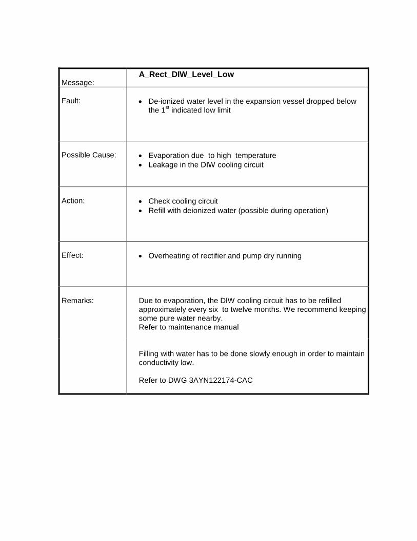
Message:A_Rect_DIW_Level_Low
Fault: · De-ionized water level in the expansion vessel dropped belowthe 1st indicated low limit
Possible Cause: · Evaporation due to high temperature· Leakage in the DIW cooling circuit
Action: · Check cooling circuit· Refill with deionized water (possible during operation)
Effect: · Overheating of rectifier and pump dry running
Remarks: Due to evaporation, the DIW cooling circuit has to be refilledapproximately every six to twelve months. We recommend keepingsome pure water nearby.Refer to maintenance manual
Filling with water has to be done slowly enough in order to maintainconductivity low.
Refer to DWG 3AYN122174-CAC

Message:A_Rect_DIW_Cooling_Pump_ Flow_Failure
Fault: · The flow of the deionized water in the closed loop rectifiercooling circuit has dropped below the allowed limit of 422.4l/min..
Possible Cause: · Air in the cooling circuit· Heavy leak in the cooling circuit· Valves closed· Failure in a water pump, changeover to standby pump· Motor starter for pump has tripped
Action: · Check if cooling circuit is in operation· Check if valves are open· Check motor starters for DIW pumps in cooling control panel.
Effect: · Overheating of thyristors· Damage of pump when running dry
Remarks: One of the two pumps is in standby. If the running pump fails, thesystem will automatically changeover to the pump in standby, if thecooling is Remote controlled.
Refer to DWG 3AYN122174-CAC SEN005109 Rev 2

Message: A_Rect_DIW_Inlet_Temperature_High/A_Rect_Diw_Output_Temperature_ High
Fault: · The cooling water temperature in the outlet pipe increasedabove 40 °C / inlet teperature increased above 45 °C
Possible Cause: · Re-cooling not in operation· Valves closed· Dirty heat exchanger· Failure in cooling control circuit· Low DIW flow· Malfunction of thermostat
Action: · Check if re-cooling circuit is in operation· Check if valves are open· Check if DIW fan motors safety switch and MCB is closed· Check thermostat and setting· Check PT100 in the DIW circuit. Check it’s wiring and calibration
Effect: · Overheating of semi conductors
Remarks: Refer to DWG 3AYN122174-CAC SEN005109 Rev 2

Message: A_Raw_Water_Inlet_ Temperature_High_Stage1/A_Raw_Water_Outlet_ Temperature_High_Stage1
Fault: · The cooling Raw water temperature in the Inlet pipe increasedabove 35 °C / Outlet temperature increased above 40 °C
Possible Cause: · Raw water-cooling not in operation· Valves closed· Failure in cooling control circuit· Low Raw water low· Malfunction of thermostat
Action: · Check if raw water-cooling circuit is in operation· Check if valves are open· Check thermostat and setting· Check PT100 in the Raw water cooling circuit. Check it’s wiring
and calibration
Effect: · Increase in Raw water temprature ,henceforth increase in DIWtemprature
Remarks: Refer to DWG 3AYN122174-CAC SEN005109 Rev 2
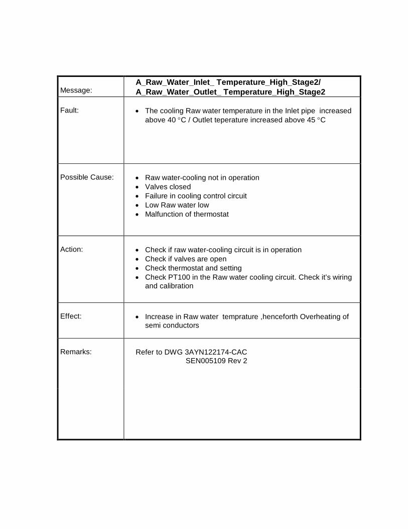
Message:A_Raw_Water_Inlet_ Temperature_High_Stage2/A_Raw_Water_Outlet_ Temperature_High_Stage2
Fault: · The cooling Raw water temperature in the Inlet pipe increasedabove 40 °C / Outlet teperature increased above 45 °C
Possible Cause: · Raw water-cooling not in operation· Valves closed· Failure in cooling control circuit· Low Raw water low· Malfunction of thermostat
Action: · Check if raw water-cooling circuit is in operation· Check if valves are open· Check thermostat and setting· Check PT100 in the Raw water cooling circuit. Check it’s wiring
and calibration
Effect: · Increase in Raw water temprature ,henceforth Overheating ofsemi conductors
Remarks: Refer to DWG 3AYN122174-CAC SEN005109 Rev 2
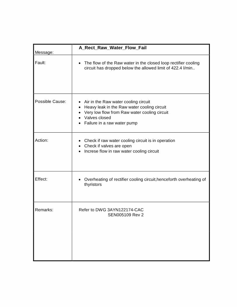
Message:A_Rect_Raw_Water_Flow_Fail
Fault: · The flow of the Raw water in the closed loop rectifier coolingcircuit has dropped below the allowed limit of 422.4 l/min..
Possible Cause: · Air in the Raw water cooling circuit· Heavy leak in the Raw water cooling circuit· Very low flow from Raw water cooling circuit· Valves closed· Failure in a raw water pump
Action: · Check if raw water cooling circuit is in operation· Check if valves are open· Increse flow in raw water cooling circuit
Effect: · Overheating of rectifier cooling circuit,henceforth overheating ofthyristors
Remarks: Refer to DWG 3AYN122174-CAC SEN005109 Rev 2
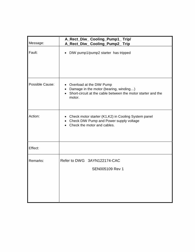
Message:A_Rect_Diw_ Cooling_Pump1_ Trip/A_Rect_Diw_ Cooling_Pump2_ Trip
Fault: · DIW pump1/pump2 starter has tripped
Possible Cause: · Overload at the DIW Pump· Damage in the motor (bearing, winding…)· Short-circuit at the cable between the motor starter and the
motor.
Action: · Check motor starter (K1,K2) in Cooling System panel· Check DIW Pump and Power supply voltage· Check the motor and cables.
Effect:
Remarks: Refer to DWG 3AYN122174-CAC
SEN005109 Rev 1
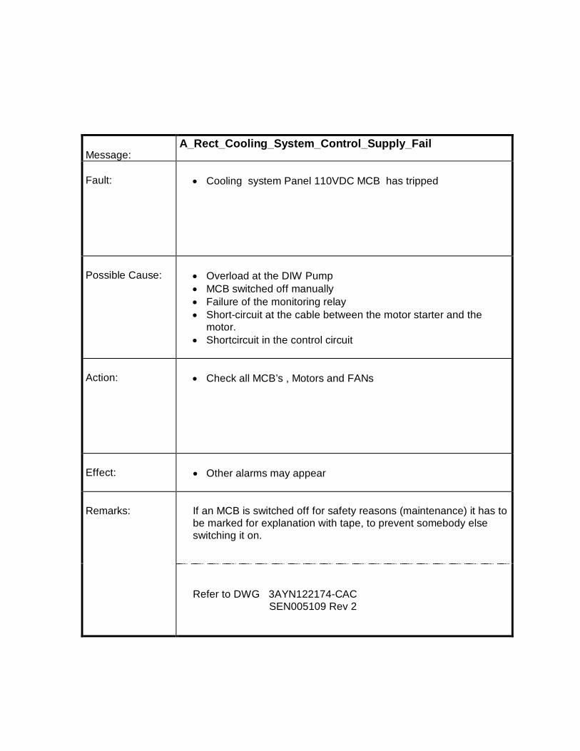
Message:A_Rect_Cooling_System_Control_Supply_Fail
Fault: · Cooling system Panel 110VDC MCB has tripped
Possible Cause: · Overload at the DIW Pump· MCB switched off manually· Failure of the monitoring relay· Short-circuit at the cable between the motor starter and the
motor.· Shortcircuit in the control circuit
Action: · Check all MCB’s , Motors and FANs
Effect: · Other alarms may appear
Remarks: If an MCB is switched off for safety reasons (maintenance) it has tobe marked for explanation with tape, to prevent somebody elseswitching it on.
Refer to DWG 3AYN122174-CAC SEN005109 Rev 2

Message:A_ Rectifier_Cooling_Fan_Fail
Fault: · DIW FAN Status Relay(C3) not oprated.
Possible Cause: · Fan On command not given from remote or local control.· Damage in the FAN (bearing, winding…)· Short-circuit at the cable between the motor starter and the FAN
Action: · Check Fan on command from pec.· motor starter in Cooling System panel fail.· Check the Fans and cables.
Effect: · DIW FAN ready staus is not OK.Diw Fan On command can notbe given.
Remarks: · Overload at the FAN· Damage in the FAN (bearing, winding…)· Short-circuit at the cable between the motor starter and the FAN
Refer to DWG 3AYN122174-CAC SEN005109 Rev 2

Message:A_RectTx_Bucholz
Fault: · Gas concentration in the Buchholz relay located on the top ofthe transformer
Possible Cause: · Short circuit between windings due to weak insulation,overvoltage, and external short circuit.
· Bad connection inside the transformer, hot spot, mechanicalfailure, short circuit in the transformer core
Action: · Release the gas from the relay, observe and record gasdevelopment during the following days and weeks.
· Oil and gas analysis can give useful hints about nature andlocation of failure
· Oil sampling and testing must be carried out by transformerspecialists who can also give advice about further steps to betaken
· Eventually cross check with the gas concentration value givenby the online system
Effect:· Destruction of transformer and environment
Remarks: This alarm might appear after months or years of operation. Aslong as it is not appearing periodically within weeks (after releasingthe gas) the behavior is normal. Otherwise consult transformerspecialist and do oil and gas analysis.
Refer to Transformer Manual
Refer to DWG 3AYN122174-CAC 620013/24/05

Message:A_RectTx_Oil_Temperature_High
Fault: · Increase of oil temperature above 90°C
Possible Cause: · Loss of transformer cooling· Transformer radiators / heat exchanger dirty, because of sludge
and sediments present in the cooling water· Loss of flow in cooling circuits due to closed valves· Abnormally high ambient temperature coupled with high load on
the rectifier unit· Oil pump not in operation· Failure in PT100, transducer or wiring· Failure of the temperature supervision thermostat
Action: · Check if valves are open· Clean, check radiators / heat exchanger· Reduce load on rectifier (if possible) to maintain constant
temperature and to avoid a trip of the system· Check PT100 located in the transformer-cooling compartment.
Check wiring and transducer· Check motor starter and control circuit
Effect: · Trip of the system after raising the temperature to trip level.· Damage of insulating material on the windings

Remarks: Refer to Transformer Manual for additional hints
Refer to DWG 3AYN122174-CAC 620013/24/05
Message:A_RectTx_Sys1_Winding_Temperature_High/A_RectTx_Sys2_Winding_Temperature_High
Fault: · Increase of star or delta bridge winding temperature above thelimit of 90 deg C
Possible Cause: · Loss of transformer cooling· Transformer radiators / heat exchanger dirty· Loss of flow in cooling circuits due to closed valves· Abnormally high ambient temperature coupled with high load on
the rectifier unit· Failure in the temperature control
Action: · Compare oil and winding temperature for future investigations· Check if valves are open· Clean, check radiators / heat exchanger· Reduce load on rectifier (if possible) to maintain constant
temperature and to avoid a trip of the system· Check motor starter and cooling control circuit

Effect: · Trip of the system after raise of the temperature to trip level· Damage of insulating material on the windings
Remarks: Refer to Transformer Manual for additional hints Refer to DWG 3AYN122174-CAC
620013/24/05
Message:A_RectTx_Oil_Level_Low
Fault: · Oil level in the transformer main tank expansion tank droppedbelow the minimum level
Possible Cause: · Low oil temperature due to light or no load condition and lowambient temperature
· Oil leak in transformer main tank· Malfunction of the indicator· Loose wiring or terminals
Action: · Check oil temperature and level· Check for any oil leak at the rectifier transformer main tank· Check indicator, wiring and terminals

Effect: · If oil level drops further the transformer could be destroyedbecause of a weak insulation of the windings and insufficientcooling.
Remarks: When filling or draining oil, the level should correspond to the oiltemperature. Higher level for high temperature and lower level forlow temperature
Refer to Transformer Manual for additional hints Refer to DWG 3AYN122174-CAC
620013/24/05
Message:A_ RectTx_Oil_ Pump1_Flow_Failure /A_RectTx_Oil_Pump2_Flow_ Failure
Fault: · The oil flow in the closed loop transformer cooling circuit hasdropped below 700lpm on one of the heat exchanger bank.
Possible Cause: · Heavy leak in the cooling circuit· Valves closed· Failure of one or two oil pump,· MCB for pump has tripped· Main incomer in has tripped
Action: · Check cooling circuit for oil· Check valve positions· Check MCBs in the transformer auxiliary panel.· Check pump; Exchange faulty pump or repair it (winding,
bearing)

Effect: · Overheating of transformer· Damage of pump when running dry
Remarks: Refer to DWG 3AYN122174-CAC 620013/24/05
Message:A_RectTX_Cooler1_Leakage/A_RectTX_Cooler2_Leakage
Fault: · Transformer differential pressure acted
Possible Cause: · Raw water input pressure into heat exchanger greaterthan oil pressure
· Closed valve – copper tubing between DPS measuringinstrument and the point tapped
· Oil pump switched off condition· Control wiring faulty (Interconnection RCP &
Transformer marshalling box)
Action:· Ensure raw water pressure lesser than oil pressure· Check associated valve positions, copper tube
connections· Check appropriate pump for the heat exchanger and
raw water inlet connected
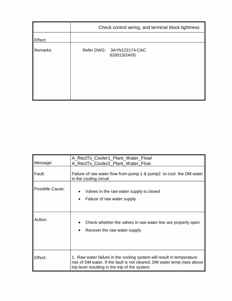
Check control wiring, and terminal block tightness
Effect:
Remarks: Refer DWG: 3AYN122174-CAC 620013/24/05
Message:A_RectTx_Cooler1_Plant_Water_Flow/A_RectTx_Cooler2_Plant_Water_Flow
Fault: Failure of raw water flow from pump 1 & pump2 to cool the DM waterin the cooling circuit
Possible Cause: · Valves in the raw water supply is closed
· Failure of raw water supply
Action:· Check whether the valves in raw water line are properly open
· Recover the raw water supply
Effect: 1. Raw water failure in the cooling system will result in temperaturerise of DM water. If the fault is not cleared, DM water temp rises abovetrip level resulting in the trip of the system

Remarks:
Refer DWG: 3AYN122174-CAC 620013/24/05
Message:A_Earthfault_In_Celline
Fault: · The earth fault monitoring cubicle has a ground fault higherthan 2.5A.
Possible Cause: · Short circuit of the cable leading to the rectifier· Short circuit of the power supply of the relay· The ground fault relay is out of order· The Rectfier cubicle has a leakage to ground· Shorcircuit in the Earthfault Monitoring Unit
Action: · Check short circuit possibility· Check wiring and load and switch it once again .· Inspect visually the Rectifier cubicle in order to find a
insulation fault

Effect: · No critical effect is to be awaited. Nevertheless themaintenance has to fix the fault because a major insulationfault could occur without detection
Remarks: Refer to DWG 3AYN122174-CAC 3AYN122174-CAG
Message:A_Rect_ Temperature_High
Fault: · The temperature in the rectifier cubicle is high
Possible Cause: · Re-cooling fans are not in operation· Dirty heat exchanger· Failure in cubicle cooling control circuit· Fans motors safety switch off· Re-cooling not in operation

Action: · Check if re-cooling circuit is in operation· Check if valves are open· Check if fan motors safety switch and MCB is closed· Check thermostats and setting
Effect: · Overheating of semi conductors
Remarks: Refer to DWG 3AYN122174-CAC 3AYN122174-CAB
Message:A_Rect_ Sys1_Fuse Monitoring Card_Failure/A_Rect_ Sys2_Fuse Monitoring Card_Failure
Fault: · Failure of Thyristor fuse monitoring Unit
Possible Cause: · Internal failure of fuse monitoring board –D141 /-D142 (+A120)

Action: · Check the fuse monitoring boards.· Check the control cable.
Effect: · As long as this alarm is present, no Thyristor fuse failure couldbe detected. Running the unit in these conditions is particularlyrisky for the semi-conductors.
Remarks: All spares in the stock are modified and t ested. However, a visualcheck for proper settings has to be done.
Refer to DWG 3AYN122174-CAC 3AYN122174-CAB
Message:A_ Rect_Sys1_Heatsink Temperature High /A_ Rect_Sys2_Heatsink Temperature High
Fault: · Temperature of one or several Heat-sink Thermostats hasincreased above 70°C
Possible Cause: · Loss of cooling due to closed valves· Re-cooling circuit is not in operation· Failure of thermostats or loose connections (open loop)

Action: · Check cooling unit and rectifier heat exchanger for dirt and openvalves
· Check wiring for open loops. Wiring loops have to be closed.
Effect: · Over-temperature could destroy semiconductor
Remarks: For wiring and location of thermostats
Refer to DWG 3AYN122174-CAC 3AYN122174-CAB
Message:A_ Rect_Sys1_First Fuse_Failure/A_ Rect_Sys2_First Fuse_Failure
Fault: · In one or several legs of the rectifier one Thyristor fuse hasblown
· A multiple Thyristor fuse failure can happen for various reasons.In most cases other signals will appear and are to be taken intoconsideration to locate the source of the fault.
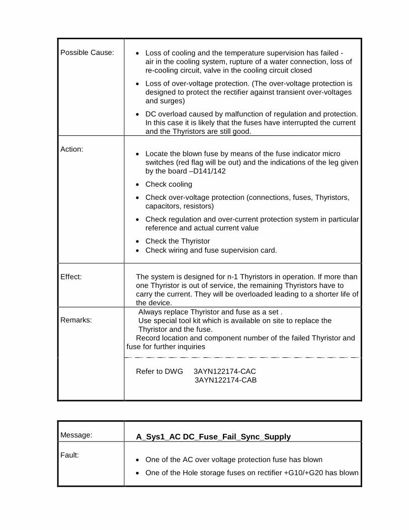
Possible Cause: · Loss of cooling and the temperature supervision has failed -air in the cooling system, rupture of a water connection, loss ofre-cooling circuit, valve in the cooling circuit closed
· Loss of over-voltage protection. (The over-voltage protection isdesigned to protect the rectifier against transient over-voltagesand surges)
· DC overload caused by malfunction of regulation and protection.In this case it is likely that the fuses have interrupted the currentand the Thyristors are still good.
Action: · Locate the blown fuse by means of the fuse indicator microswitches (red flag will be out) and the indications of the leg givenby the board –D141/142
· Check cooling
· Check over-voltage protection (connections, fuses, Thyristors,capacitors, resistors)
· Check regulation and over-current protection system in particularreference and actual current value
· Check the Thyristor· Check wiring and fuse supervision card.
Effect: The system is designed for n-1 Thyristors in operation. If more thanone Thyristor is out of service, the remaining Thyristors have tocarry the current. They will be overloaded leading to a shorter life ofthe device.
Remarks: Always replace Thyristor and fuse as a set . Use special tool kit which is available on site to replace the
Thyristor and the fuse. Record location and component number of the failed Thyristor andfuse for further inquiries
Refer to DWG 3AYN122174-CAC 3AYN122174-CAB
Message: A_Sys1_AC DC_Fuse_Fail_Sync_Supply
Fault: · One of the AC over voltage protection fuse has blown
· One of the Hole storage fuses on rectifier +G10/+G20 has blown
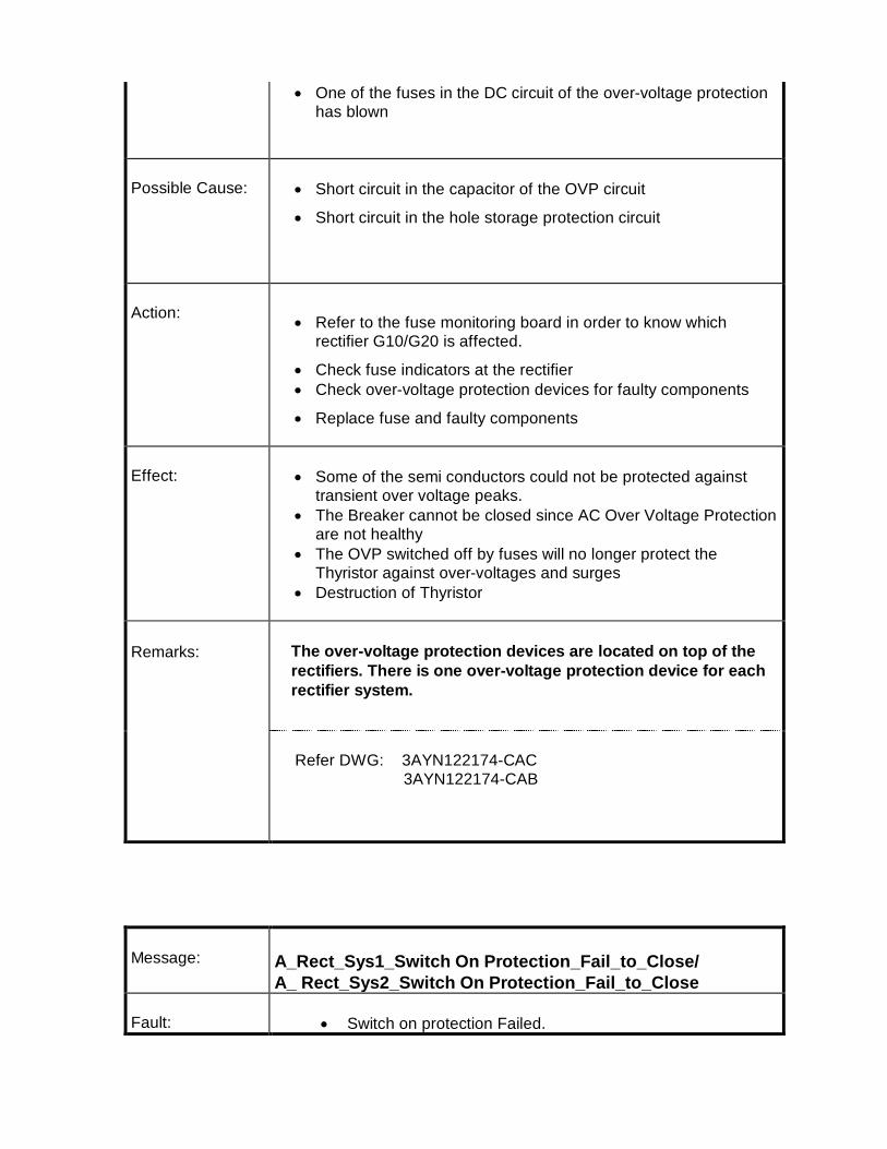
· One of the fuses in the DC circuit of the over-voltage protectionhas blown
Possible Cause: · Short circuit in the capacitor of the OVP circuit
· Short circuit in the hole storage protection circuit
Action: · Refer to the fuse monitoring board in order to know whichrectifier G10/G20 is affected.
· Check fuse indicators at the rectifier· Check over-voltage protection devices for faulty components
· Replace fuse and faulty components
Effect: · Some of the semi conductors could not be protected againsttransient over voltage peaks.
· The Breaker cannot be closed since AC Over Voltage Protectionare not healthy
· The OVP switched off by fuses will no longer protect theThyristor against over-voltages and surges
· Destruction of Thyristor
Remarks: The over-voltage protection devices are located on top of therectifiers. There is one over-voltage protection device for eachrectifier system.
Refer DWG: 3AYN122174-CAC 3AYN122174-CAB
Message: A_Rect_Sys1_Switch On Protection_Fail_to_Close/A_ Rect_Sys2_Switch On Protection_Fail_to_Close
Fault: · Switch on protection Failed.
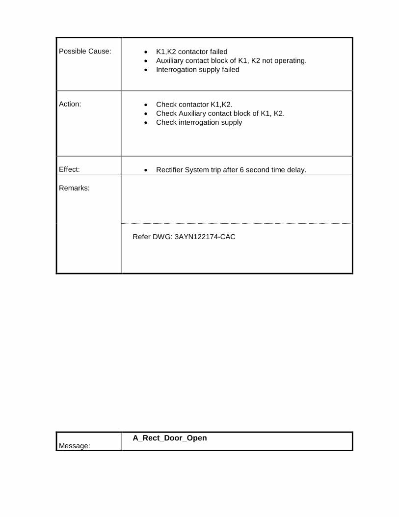
Possible Cause: · K1,K2 contactor failed· Auxiliary contact block of K1, K2 not operating.· Interrogation supply failed
Action: · Check contactor K1,K2.· Check Auxiliary contact block of K1, K2.· Check interrogation supply
Effect: · Rectifier System trip after 6 second time delay.
Remarks:
Refer DWG: 3AYN122174-CAC
Message:A_Rect_Door_Open

Fault: · Rectifier cubicle door is open
Possible Cause: · Entry to the rectifier compartment for maintenance works wasattempted while unit was switched on.
Action: · Close rectifier compartment doors· Close the DC isolators· Check that cubicle fans are running again· Instruct personnel on proper operation of equipment.
Effect: · Danger to personal
Remarks: Do not enter to rectifier compartment while the unit is inoperation!
Ensure that the rectifier compartment is empty before re-energizingthe transformer.
Refer to DWG 3AYN122174-CAC 3AYN122174-CAB
A_FOCS_General_Alarm

Message:
Fault:· Fiber optic current sensor unit alarm.
Possible Cause:· PT100 temperature LOW or HIGH alarm.· PT100 measurement failure· IFSM temperature LOW or HIGH alarm· IFSM error
Action: Check sensor electronics PPD 115 controller for following:· One red LED to indicate device errors.· Three green LEDs to indicate normal operation conditions.· Two yellow LEDs for temperature and IFSM monitoring.
Effect: · Relay 3 in PPD 115 is Denergized , indicating fault.
Remarks: · FOCS controller PPD 115 needs to be reset.· Check for any temperature related problems.
For additional information refer:3BHS207392 ZAB E01
Refer DWG 3AYN122174-CAC 3AYN122174-CAF

Message:A_RCP_DC_Control_Voltage_MCB_Failure
Fault: · MCB(–Q600) providing the 110V DC control voltage hastripped.
Possible Cause: · Overload of this MCB· MCB switched off manually· Failure of the monitoring relay
Action: · Check which MCB is switched off· Check its wiring and load· Switch it on again if it is not switched off for safetyreasons· Verify the 110V DC, 1ph, is present from the ACDCDB
Effect: · Other alarms may appear
If an MCB is switched off for safety reasons (maintenance,..)it has to be marked for explanation with tape, to preventsomebody else switching it on.
Refer Scheme 3AYN122174-CAC

Message:A_RCP_1-Phase_Light_Voltage_MCB_Failure
Fault: · The any one of the MCB Q500,Q501,Q503 have tripped.
Possible Cause: · Overload of the MCB· MCB switched off manually (for maintenance or
troubleshooting reason)· Short circuit in the lighting / socket
Action: · Check which MCB has tripped· Check MCB wiring and load and switch it once again if it
is not switched off for safety reasons.
Effect: · No critical effect is to be awaited. Nevertheless themaintenance has to fix the fault
If a MCB is switched off for safety reasons (i.e. maintenance)it has to be marked for explanation with tape, to preventsomebody else switching it on.
Refer to DWG 3AYN122174-CAC

Message:A_Rect_TX_Star_Protection_Fail/A_Rect_TX_Delta_Protection_Fail
Fault: · Trip due to Rectifier Transformer over-current – star / deltasystem. The over-current relay –F301,=F302 SPAJ 140C of star /delta system has tripped.
Possible Cause:· Transformer in rush current· Transformer internal faults: winding fault· Rectifier short circuit: insulation breakdown due to high
temperature, moisture and chemicals, carbonization and surfacetracking
· Bus-bar overload, malfunction of current regulation.· Loss of supply voltage
Action: · Before resetting the protection relay SPAJ 140C refer to itsmanual (in Part 3 of the User's Manual). Take readings of faultindication (MODE) and fault level (VALUE) for further inquires.
· Check protection relay settings· Check transformer ratio, measurement of exciting current,
resistance and mutual inductance between windings.· Check rectifier and regulation circuits
Effect: · Overload and destruction of transformer and rectifier
Remarks: Refer to Transformer Manual for additional hints
Refer to DWG 3AYN122174-CAC 620013/24/05

Message:A_Breaker_Trip_Circuit_Supervision
Fault: Supervision relay F601 in RCP operated
Possible Cause: Power supply for the breaker coil failed
Action: Check the breaker panel circuits
Effect: The breaker coil will not operate
Remarks: Refer to breaker drawings for addition hints.
Refer DWG. 3AYN122174-CAC

Message:T_Rect_Diw_Output_Temp_ High/T_Rect_DIW_Inlet_ Temperature_High
Fault: · The cooling water temperature in the outlet pipe (from rectifier tocooling unit) increased above 50 °C / inlet pipe to rectifierincreased above 45 °C
Possible Cause: · Re-cooling not in operation· Valves closed· Dirty heat exchanger· Failure in cooling control circuit· Heat exchanger fan switched off
Action: · Check if re-cooling circuit is in operation· Check if valves are open· Check if DIW pump MCB are closed· Check if cubicle fan motor MCB is closed
Effect: · Overheating of semi-conductors
Remarks: Do not re-energize the unit before the temperature dropsbelow critical level.
The primary breaker will be blocked in the off position as long asthe trip is present.
Refer to DWG 3AYN122174-CAC 3AYN122174-CAB
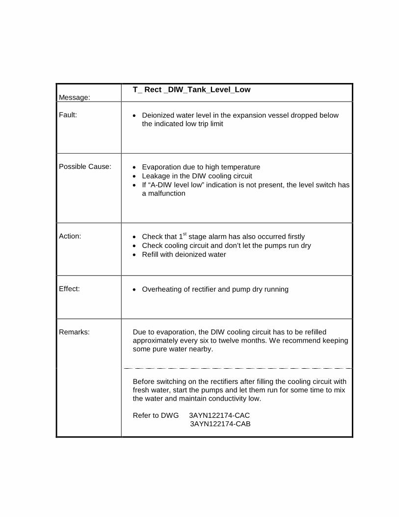
Message:T_ Rect _DIW_Tank_Level_Low
Fault: · Deionized water level in the expansion vessel dropped belowthe indicated low trip limit
Possible Cause: · Evaporation due to high temperature· Leakage in the DIW cooling circuit· If “A-DIW level low” indication is not present, the level switch has
a malfunction
Action: · Check that 1st stage alarm has also occurred firstly· Check cooling circuit and don’t let the pumps run dry· Refill with deionized water
Effect: · Overheating of rectifier and pump dry running
Remarks: Due to evaporation, the DIW cooling circuit has to be refilledapproximately every six to twelve months. We recommend keepingsome pure water nearby.
Before switching on the rectifiers after filling the cooling circuit withfresh water, start the pumps and let them run for some time to mixthe water and maintain conductivity low.
Refer to DWG 3AYN122174-CAC 3AYN122174-CAB
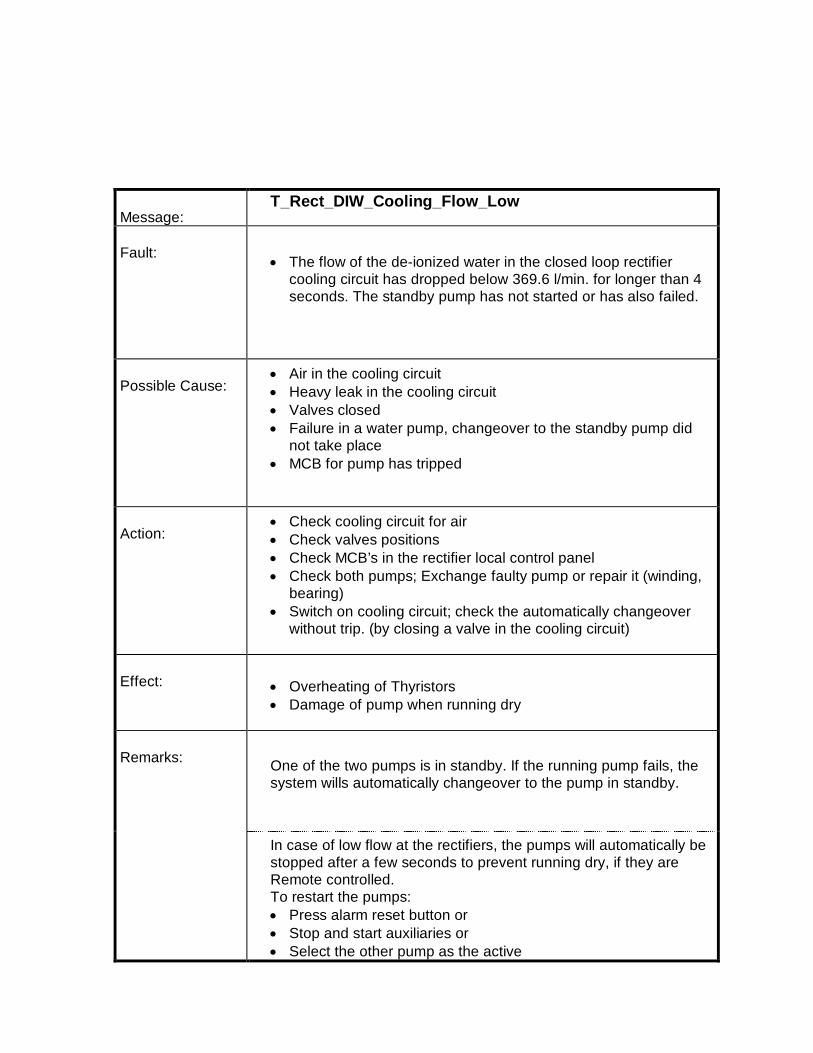
Message:T_Rect_DIW_Cooling_Flow_Low
Fault:· The flow of the de-ionized water in the closed loop rectifier
cooling circuit has dropped below 369.6 l/min. for longer than 4seconds. The standby pump has not started or has also failed.
Possible Cause:· Air in the cooling circuit· Heavy leak in the cooling circuit· Valves closed· Failure in a water pump, changeover to the standby pump did
not take place· MCB for pump has tripped
Action:· Check cooling circuit for air· Check valves positions· Check MCB’s in the rectifier local control panel· Check both pumps; Exchange faulty pump or repair it (winding,
bearing)· Switch on cooling circuit; check the automatically changeover
without trip. (by closing a valve in the cooling circuit)
Effect: · Overheating of Thyristors· Damage of pump when running dry
Remarks: One of the two pumps is in standby. If the running pump fails, thesystem wills automatically changeover to the pump in standby.
In case of low flow at the rectifiers, the pumps will automatically bestopped after a few seconds to prevent running dry, if they areRemote controlled.To restart the pumps:· Press alarm reset button or· Stop and start auxiliaries or· Select the other pump as the active

Message:T_Rect _Diw_Conductivity_High
Fault: · The conductivity of the de-ionized cooling water, measured withthe conductivity meter in the cooling unit has risen above thelimit of 10 µS/cm.
· The measuring instrument is defective· The conductivity sensor is faulty
Possible Cause: · Recently filled distilled water has not been circulating throughthe de-ionizer long enough
· Too little flow through de-ionizer· The resin of the de-ionizer is exhausted
Action: · Increase flow through de-ionizer and observe the conductivityfor a few hours
· If the conductivity remains high, replace the resin· The cartridge has to be replaced
Effect: · High conductivity of cooling water can cause leakage currents inthe rectifier and destroy the equipment
Remarks: Use only resin recommended by ABB or approved equal.

Refer to manual of cooling unit and cooling flow diagram.
Refer to DWG 3AYN122174-CAC SEN005109 Rev 2
Message:T_RectTx_Bucholtz
Fault:· The Buchholz relay of rectifier transformer has tripped due to
strong oil flow in the transformer tank
Possible Cause:· Short circuit between windings due to weak insulation,
over voltage, external short circuit.· Bad connection inside the transformer, hot spot, mechanical
failure, short circuit in the transformer core.
Action:· Oil and gas analysis can give useful hints about nature and
location of failure· Oil sampling and testing must be carried out by transformer
specialists who can also give advice about further steps to betaken
· Transformer should not be taken back to operation beforetransformer has been inspected carefully
· Eventually cross check with the gas concentration value givenby the online system

Effect:· Destruction of transformer and environment
Remarks: Do not re-energize the transformer before cause of tripping isknown, rectified and a safe operation is reestablished.
Refer to Transformer Manual
Refer to DWG 3AYN122174-CAC 620013/24/05
Message:T_RectTx_Oil_Level_Low
Fault: · Drop of the oil level in the transformer expansion tank on the topof the transformer below indicated minimum level
Possible Cause: · Low oil temperature· Oil leakage· Low oil level
Action: · Check oil temperature and level· Check for oil leakage· Refill transformer oil
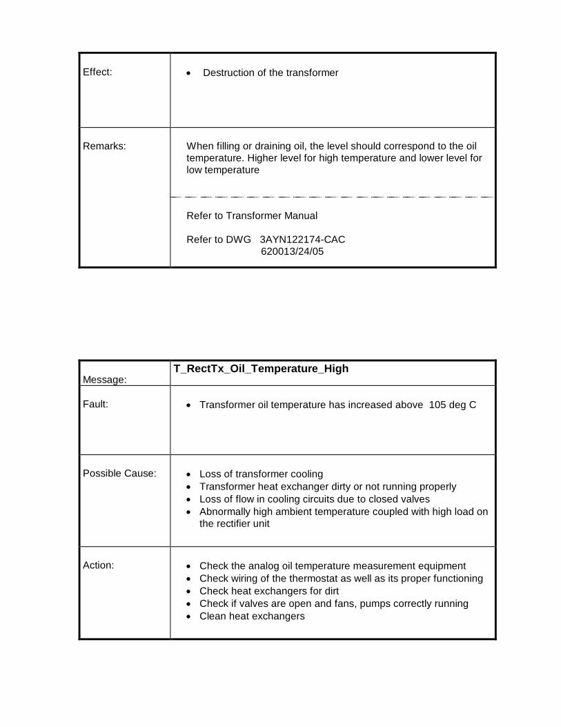
Effect: · Destruction of the transformer
Remarks: When filling or draining oil, the level should correspond to the oiltemperature. Higher level for high temperature and lower level forlow temperature
Refer to Transformer Manual
Refer to DWG 3AYN122174-CAC 620013/24/05
Message:T_RectTx_Oil_Temperature_High
Fault: · Transformer oil temperature has increased above 105 deg C
Possible Cause: · Loss of transformer cooling· Transformer heat exchanger dirty or not running properly· Loss of flow in cooling circuits due to closed valves· Abnormally high ambient temperature coupled with high load on
the rectifier unit
Action: · Check the analog oil temperature measurement equipment· Check wiring of the thermostat as well as its proper functioning· Check heat exchangers for dirt· Check if valves are open and fans, pumps correctly running· Clean heat exchangers

Effect: · Damage of insulating material on the windings· Primary breaker is blocked in the off position as long as the trip
is present.
Remarks: Do not re-energize the transformer Before the temperature drops below a critical level.
Refer to Transformer Manual for additional hints
Refer to DWG 3AYN122174-CAC 620013/24/05
Message:T_RectTx_Pressure_ReliefValve_Operated
Fault: · Rectifier Transformer oil pressure relief
Possible Cause: · Short circuit between windings due to weak insulation· Over voltage· External short circuit· Bad connection or mechanical failure in the transformer
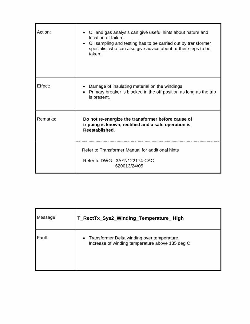
Action: · Oil and gas analysis can give useful hints about nature andlocation of failure.
· Oil sampling and testing has to be carried out by transformerspecialist who can also give advice about further steps to betaken.
Effect: · Damage of insulating material on the windings· Primary breaker is blocked in the off position as long as the trip
is present.
Remarks: Do not re-energize the transformer before cause oftripping is known, rectified and a safe operation isReestablished.
Refer to Transformer Manual for additional hints
Refer to DWG 3AYN122174-CAC 620013/24/05
Message: T_RectTx_Sys2_Winding_Temperature_ High
Fault: · Transformer Delta winding over temperature.Increase of winding temperature above 135 deg C

Possible Cause: · Loss of transformer cooling· Transformer heat exchanger dirty· Loss of flow in cooling circuits· Abnormally high ambient temperature coupled with high load on
the rectifier unit
Action: · Check winding temperature device for proper operation· Compare oil and winding temperature for further investigations· Clean heat exchanger
Refer to DWG 3AYN122174-CAC3620013/24/10 Rev_01
Effect: · Damage of insulating material on the windings· Primary breaker is blocked in the off position as long as the trip
is present.
Remarks: Do not re-energize the transformerBefore the temperature drops below critical level
Refer to Transformer Manual for additional hints
Message: T_RectTx_Sys1_Winding_Temperature_ High
Fault: · Transformer Star winding over temperature.Increase of winding temperature above 135 deg C

Possible Cause: · Loss of transformer cooling· Transformer heat exchanger dirty· Loss of flow in cooling circuits· Abnormally high ambient temperature coupled with high load on
the rectifier unit
Action: · Check winding temperature device for proper operation· Compare oil and winding temperature for further investigations· Clean heat exchanger
Refer to DWG 3AYN122174-CAC3620013/24/10 Rev_01
Effect: · Damage of insulating material on the windings· Primary breaker is blocked in the off position as long as the trip
is present.
Remarks: Do not re-energize the transformerBefore the temperature drops below critical level
Refer to Transformer Manual for additional hints
Message:T_RectTx_ Primary_Star_Over_Current
Fault:· Trip due to Rectifier Transformer over-current– star system. The
over-current relay –F301 SPAJ 140C of star system has tripped.

Possible Cause:· Transformer in rush current· Transformer internal faults: winding fault· Rectifier short circuit: insulation breakdown due to high
temperature, moisture and chemicals, carbonization and surfacetracking
· Bus-bar overload, malfunction of current regulation.· Loss of supply voltage
Action: · Before resetting the protection relay SPAJ 140C refer to its manual (inPart 3 of the User's Manual). Take readings of fault indication (MODE)and fault level (VALUE) for further inquires.
· Check protection relay settings· Check transformer ratio, measurement of exciting current, resistance
and mutual inductance between windings.· Check rectifier and regulation circuits
Refer to Rectifier Control Circuit Diagram 3AYN128156-CAC
Effect: · Overload and destruction of transformer and rectifier
Remarks: Do not proceed with operation without consulting transformerrespectively rectifier expert if there are any indications, whichcannot be verified!
Before withdrawing the SPAJ 140C from its casing switch off theauxiliary supply.When replacing the relay with a spare, modify its settings accordingto the setting table.
In most cases other transformer/rectifier related signals would alsobe activated, which will be helpful for inquiries.
Message: T_RectTx_ Primary_Delta_Over_Current

Fault:· Trip due to Rectifier Transformer over-current - delta system. The
over-current relay –F302 SPAJ 140C of DELTA system hastripped.
Possible Cause:· Transformer in rush current· Transformer internal faults: winding fault· Rectifier short circuit: insulation breakdown due to high
temperature, moisture and chemicals, carbonization and surfacetracking
· Bus-bar overload, malfunction of current regulation.· Loss of supply voltage
Action: · Before resetting the protection relay SPAJ 140C refer to its manual (inPart 3 of the User's Manual). Take readings of fault indication (MODE)and fault level (VALUE) for further inquires.
· Check protection relay settings· Check transformer ratio, measurement of exciting current, resistance
and mutual inductance between windings.· Check rectifier and regulation circuits
Refer to Rectifier Control Circuit Diagram 3AYN128156-CAC
Effect: · Overload and destruction of transformer and rectifier
Remarks: Do not proceed with operation without consulting transformerrespectively rectifier expert if there are any indications, whichcannot be verified!
Before withdrawing the SPAJ 140C from its casing switch off theauxiliary supply.When replacing the relay with a spare, modify its settings accordingto the setting table.
In most cases other transformer/rectifier related signals would alsobe activated, which will be helpful for inquiries.
Message:T_Rect_Sys1_Second_ Fuse_ Failure/T_Rect_Sys2_Second_ Fuse_ Failure

Fault: · In one or several legs of the rectifier more than one Thyristorfuse has blown
· A multiple Thyristor fuse failure can happen for various reasons.In most cases other signals will appear and are to be taken intoconsideration to locate the source of the fault.
Possible Cause: · Loss of cooling and the temperature supervision has failed -air in the cooling system, rupture of a water connection, loss of
re-cooling circuit, valve in the cooling circuit closed.· Loss of over-voltage protection. (The over-voltage protection is
designed to protect the rectifier against transient over-voltagesand surges).
· DC overload caused by malfunction of regulation and protection.In this case it is likely that the fuses have interrupted the currentand the Thyristors are still good.
Action: · Locate the blown fuse by means of the fuse indicator microswitches (red flag will be out)
· Check cooling· Check over-voltage protection (connections, fuses, Thyristors,
capacitors, resistors)· Check regulation and over-current protection system in particular
reference and actual current value· Check wiring and fuse supervision card.
Effect: · The system is designed for n-1 Thyristors in operation. If morethan one Thyristor is out of service, the remaining Thyristorshave to carry the current. They will be overloaded leading to ashorter life of the device.
Remarks: Always replace Thyristor and fuse as a set. Use special tool kit which is available on site to replace the
Thyristor and the fuse
Record location and component number of the failed Thyristor andfuse for further inquiries
Refer to DWG 3AYN122174-CAC 3AYN122174-CAB
Message:T_Rect_Sys1_Heatsink Temperature High/

T_ Rect_Sys2_HeatSink Temperature High
Fault: · Temperature of one or several Heat-sink Thermostats hasincreased above 75°C
Possible Cause: · Loss of cooling due to closed valves· Re-cooling circuit is not in operation· Failure of thermostats or open loop
Action: · Check cooling unit and rectifier heat exchanger for dirt and openvalves
· Check wiring for open loops. Wiring loops have to be closed.
Effect: · Over-temperature could destroy semiconductor
Remarks: Do not re-energize the unit before the temperature hasdropped below critical level
The primary breaker will be blocked in the off position as long asthe trip is present
For wiring of thermostats refer to:DWG 3AYN122174-CAC 3AYN122174-CAB

Message: T_Rect_Sys1_Over Voltage_ Prot_ Fuse_ Failure /T_Rect_Sys2_Over Voltage_ Prot_ Fuse_ Failure
Fault: · One of the AC over voltage protection fuse has blown
· One of the Hole storage fuses on rectifier +G10/+G20 has blown
Possible Cause: · Short circuit in the capacitor of the OVP circuit
· Short circuit in the hole storage protection circuit
Action: · Refer to the fuse monitoring board in order to know whichrectifier G10/G20 is affected.
· Check fuse indicators at the rectifier
Effect: · Some of the semi conductors could not be protected againsttransient over voltage peaks.
· The Breaker cannot be closed since AC Over Voltage Protectionare not healthy
Remarks:

Message: T_MB_Electrical_Fault
Fault: The system tripped on fault from the Transformer HT breaker end.
Possible Cause: · Master trip relay at the breaker panel activated
· Actual fault occurred at the HT breaker panel
· Control circuit wiring fault
Action: · Check for actual fault at the breaker end
· Reset the master trip relay at the HT breaker panel
· Check the control wiring between breaker panel & rectifiercontrol panel and internal wiring of RCP
Effect: Trip the system and the breaker locked in off position
Remarks:Do not Energize the Transformer until fault is cleared.

Message:T_RCP_EMERG_STOP
Fault: · The unit was switched off by pressing on the EMERGENCY OFFpush button located on the RCP.
Possible Cause: · Observation of high danger for persons or equipment or bothand activation of emergency off
Action: · Check the reason for pushing the emergency off· Check for personnel safety· Instruct personnel on proper operation of equipment· Reset the emergency off push button
Refer to DWG 3AYN122174-CAC
Effect: · Danger to personnel or equipment
Remarks: Do not re-energize the transformer into operation beforechecking reason for the Emergency Off.The rectifier units can not be switched on again as long as theemergency off button is not released