
Recrystallisation of Practical Mechanically Alloyed Iron ... · Recrystallisation of Practical...
28
Recrystallisation of Practical Mechanically Alloyed Iron–Base and and Nickel–Base Superalloys Materials Science and Engineering A223 (1997) 64-77 H. K. D. H. Bhadeshia University of Cambridge/JRDC Department of Materials Science and Metallurgy Pembroke Street, Cambridge CB2 3QZ, U.K. Abstract Commercialised mechanically alloyed yttria dispersion strengthened alloys exhibit un- usual recrystallisation behaviour. In spite of their large stored energy content, they tend to recrystallise at temperatures close to melting. The recrystallised microstruc- ture is often very coarse and highly anisotropic, characterised by columnar grains. Such a microstructure is often referred to as being “directional recrystallised”. This and other features of these unique alloys are reviewed. It is found that many of the observed peculiarities can be attributed to the ultra–fine grained structure present prior to the recrystallisation heat–treatment. In some cases the manufacturing pro- cess tends to align the dispersoid particles along the principal fabrication direction. This in turn encourages recrystallisation to be directional. INTRODUCTION Some of the most successful mechanically alloyed materials include the oxide dispersion strengthened iron–base and nickel–base superalloys. Their recrystallisation behaviour is pecu- liar and is the subject of this review. During heat treatment of the consolidated mechanically alloyed (MA) powders, the bulk samples recrystallise into remarkably anisotropic and coarse columnar grain structures. In addition, recrystallisation usually does not occur until temper- atures close to melting are reached [1–3]. The mechanical alloying process itself has been reviewed elsewhere [1–4]. Briefly, it in- volves the creation of an alloy by the intense mechanical deformation of mixtures of elemental or master–alloy powders (Fig. 1). The powders are then consolidated by various combinations of hot–isostatic pressing and extrusion; the alloys in this condition are usually too hard to use. They are therefore heat–treated, either isothermally or in a temperature gradient to induce recrystallisation. Mechanical alloying permits the usual limits of solubility imposed by solidifi- cation to be exceeded, but in addition, dispersoid particles (such as oxides) can be introduced uniformly into bulk materials. It is this latter facility which has led to commercial exploita- tion on a large scale. The mechanical alloying process is a relatively difficult manufacturing method. Variations in processing conditions (which are seldom revealed) can completely change 1
Transcript of Recrystallisation of Practical Mechanically Alloyed Iron ... · Recrystallisation of Practical...
Recrystallisation of Practical Mechanically Alloyed
Iron–Base and and Nickel–Base Superalloys
Materials Science and Engineering A223 (1997) 64-77
H. K. D. H. BhadeshiaUniversity of Cambridge/JRDC
Department of Materials Science and MetallurgyPembroke Street, Cambridge CB2 3QZ, U.K.
Abstract
Commercialised mechanically alloyed yttria dispersion strengthened alloys exhibit un-usual recrystallisation behaviour. In spite of their large stored energy content, theytend to recrystallise at temperatures close to melting. The recrystallised microstruc-ture is often very coarse and highly anisotropic, characterised by columnar grains.Such a microstructure is often referred to as being “directional recrystallised”. Thisand other features of these unique alloys are reviewed. It is found that many of theobserved peculiarities can be attributed to the ultra–fine grained structure presentprior to the recrystallisation heat–treatment. In some cases the manufacturing pro-cess tends to align the dispersoid particles along the principal fabrication direction.This in turn encourages recrystallisation to be directional.
INTRODUCTION
Some of the most successful mechanically alloyed materials include the oxide dispersion
strengthened iron–base and nickel–base superalloys. Their recrystallisation behaviour is pecu-
liar and is the subject of this review. During heat treatment of the consolidated mechanically
alloyed (MA) powders, the bulk samples recrystallise into remarkably anisotropic and coarse
columnar grain structures. In addition, recrystallisation usually does not occur until temper-
atures close to melting are reached [1–3].
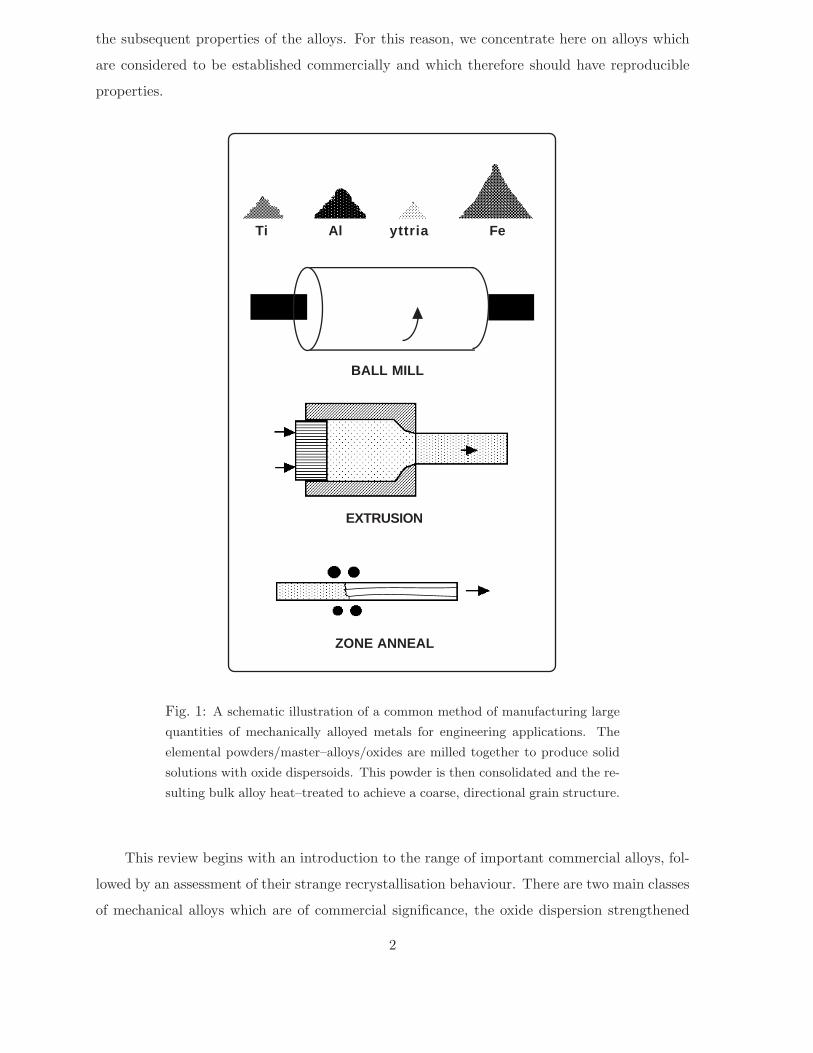
The mechanical alloying process itself has been reviewed elsewhere [1–4]. Briefly, it in-
volves the creation of an alloy by the intense mechanical deformation of mixtures of elemental
or master–alloy powders (Fig. 1). The powders are then consolidated by various combinations
of hot–isostatic pressing and extrusion; the alloys in this condition are usually too hard to use.
They are therefore heat–treated, either isothermally or in a temperature gradient to induce
recrystallisation. Mechanical alloying permits the usual limits of solubility imposed by solidifi-
cation to be exceeded, but in addition, dispersoid particles (such as oxides) can be introduced
uniformly into bulk materials. It is this latter facility which has led to commercial exploita-
tion on a large scale. The mechanical alloying process is a relatively difficult manufacturing
method. Variations in processing conditions (which are seldom revealed) can completely change
1
FeyttriaAlTi
BALL MILL
EXTRUSION
ZONE ANNEAL
the subsequent properties of the alloys. For this reason, we concentrate here on alloys which
are considered to be established commercially and which therefore should have reproducible
properties.
Fig. 1: A schematic illustration of a common method of manufacturing large
quantities of mechanically alloyed metals for engineering applications. The
elemental powders/master–alloys/oxides are milled together to produce solid
solutions with oxide dispersoids. This powder is then consolidated and the re-
sulting bulk alloy heat–treated to achieve a coarse, directional grain structure.
This review begins with an introduction to the range of important commercial alloys, fol-
lowed by an assessment of their strange recrystallisation behaviour. There are two main classes
of mechanical alloys which are of commercial significance, the oxide dispersion strengthened
2
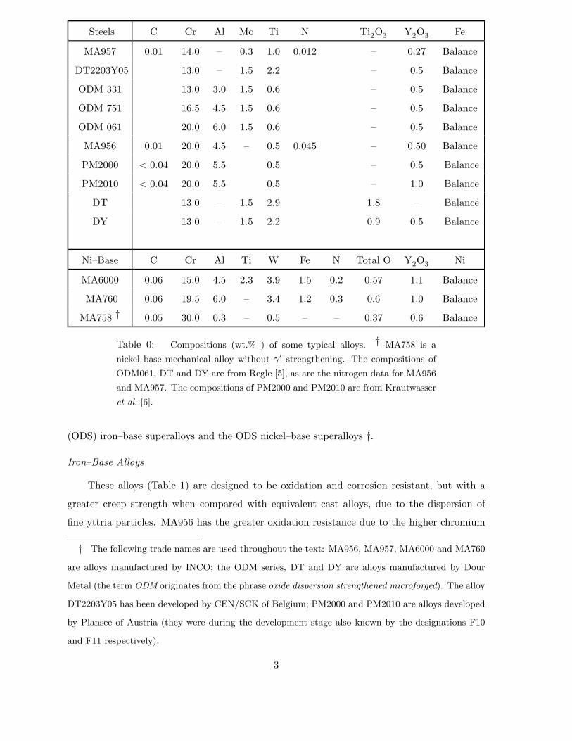
Steels C Cr Al Mo Ti N Ti2O3 Y2O3 Fe
MA957 0.01 14.0 – 0.3 1.0 0.012 – 0.27 Balance
DT2203Y05 13.0 – 1.5 2.2 – 0.5 Balance
ODM 331 13.0 3.0 1.5 0.6 – 0.5 Balance
ODM 751 16.5 4.5 1.5 0.6 – 0.5 Balance
ODM 061 20.0 6.0 1.5 0.6 – 0.5 Balance
MA956 0.01 20.0 4.5 – 0.5 0.045 – 0.50 Balance
PM2000 < 0.04 20.0 5.5 0.5 – 0.5 Balance
PM2010 < 0.04 20.0 5.5 0.5 – 1.0 Balance
DT 13.0 – 1.5 2.9 1.8 – Balance
DY 13.0 – 1.5 2.2 0.9 0.5 Balance
Ni–Base C Cr Al Ti W Fe N Total O Y2O3 Ni
MA6000 0.06 15.0 4.5 2.3 3.9 1.5 0.2 0.57 1.1 Balance
MA760 0.06 19.5 6.0 – 3.4 1.2 0.3 0.6 1.0 Balance
MA758 † 0.05 30.0 0.3 – 0.5 – – 0.37 0.6 Balance
Table 0: Compositions (wt.% ) of some typical alloys. † MA758 is a
nickel base mechanical alloy without γ′ strengthening. The compositions of
ODM061, DT and DY are from Regle [5], as are the nitrogen data for MA956
and MA957. The compositions of PM2000 and PM2010 are from Krautwasser
et al. [6].
(ODS) iron–base superalloys and the ODS nickel–base superalloys †.
Iron–Base Alloys
These alloys (Table 1) are designed to be oxidation and corrosion resistant, but with a
greater creep strength when compared with equivalent cast alloys, due to the dispersion of
fine yttria particles. MA956 has the greater oxidation resistance due to the higher chromium
† The following trade names are used throughout the text: MA956, MA957, MA6000 and MA760
are alloys manufactured by INCO; the ODM series, DT and DY are alloys manufactured by Dour
Metal (the term ODM originates from the phrase oxide dispersion strengthened microforged). The alloy
DT2203Y05 has been developed by CEN/SCK of Belgium; PM2000 and PM2010 are alloys developed
by Plansee of Austria (they were during the development stage also known by the designations F10
and F11 respectively).
3
concentration, and its large aluminium content. The presence of yttria suppresses the spalling
of the protective alumina films by trapping sulphur at the particle/matrix interfaces and hence
reducing its segregation to the oxide/metal interface [Ikeda et al., 1995]. All of the steels
listed are supposed to be ferritic. Normal ferritic steels tend to undergo a marked loss in creep
strength at temperatures in excess of 600 ◦C; the ODS alloys discussed here can in principle
be used at much higher temperatures.
The ferritic state also makes the iron–base alloys less susceptible to radiation induced
swelling. MA957 and a similar steel DT2203Y05 are therefore designed for nuclear reactor
applications, for use in a liquid sodium environment at temperatures of the order of 700◦C. Both have a high void swelling resistance, and a low carbon concentration in order to
avoid the formation of titanium carbides. The titanium is meant to combine with chromium,
molybdenum and iron to form a stable b.c.c. FeCrTiMo intermetallic χ–phase during ageing at
around 800 ◦C, which can further boost the creep strength. The rupture strength of ODM751
is larger than that of MA956 [7]. ODM751 has an additional 1.5 wt.% Mo which, either via
the χ–phase or through solid solution strengthening, presumably adds to the creep strength
of ODM751. However, the results are confusing because PM2000, which does not contain
molybdenum, virtually matches the rupture strength of ODM751.
Nickel–Base Alloys
The nickel–base alloys MA6000 and MA760 are both γ′ strengthened, as in conventional
nickel–base superalloys; the dispersion strengthening with yttria allows the strength to be
maintained to much higher temperatures. For example, at 1093 ◦C, the 1000 hour rupture
strength of MA6000 is twice that of conventional nickel–base superalloys. For reasons which
are not clear, the (low and high cycle) fatigue resistance of MA6000 is much better than that
of conventional alloys, as is its thermal fatigue resistance [2].
A lot of the oxidation resistance of MA6000 relies on the formation of chromia at the
surface. However, chromia is not very resistant to sulphidation. Resistance to sulphide attack
is important in industrial gas turbine manufacture, where the ODS alloys have applications as
vanes. MA760 has a higher sulphidation and oxidation resistance, due to its higher chromium
and aluminium concentrations, the latter inducing the formation of surface alumina [8].
The reported solidus temperatures and densities of some of the alloys are listed in Table 2.
Similar data do not seem to be available in the published literature for the other alloys listed
in Table 1. There is nothing unusual in these data, but they are relevant in two respects.
Firstly, it will be seen later that the recrystallisation temperatures of both the iron and nickel
base alloys are generally close to the temperature at which melting begins. Secondly, the
4
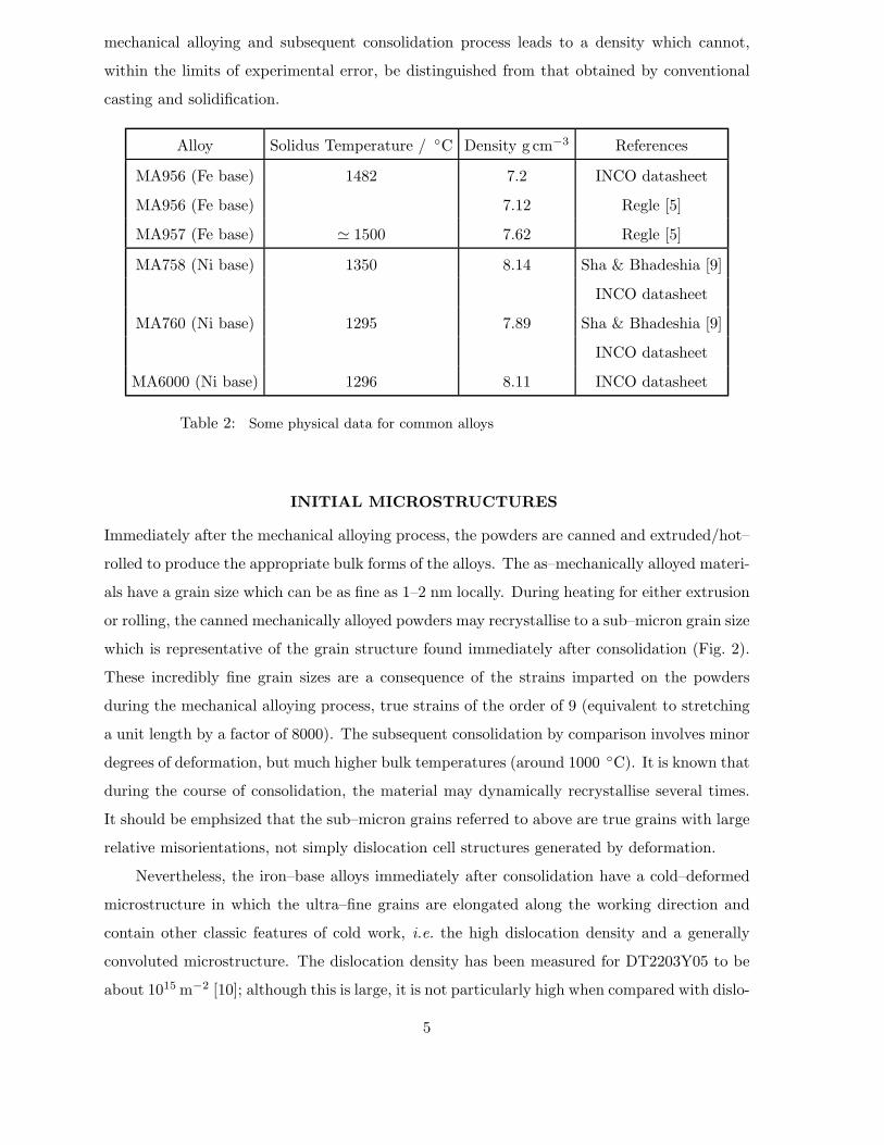
mechanical alloying and subsequent consolidation process leads to a density which cannot,
within the limits of experimental error, be distinguished from that obtained by conventional
casting and solidification.
Alloy Solidus Temperature / ◦C Density g cm−3 References
MA956 (Fe base) 1482 7.2 INCO datasheet
MA956 (Fe base) 7.12 Regle [5]
MA957 (Fe base) � 1500 7.62 Regle [5]
MA758 (Ni base) 1350 8.14 Sha & Bhadeshia [9]
INCO datasheet
MA760 (Ni base) 1295 7.89 Sha & Bhadeshia [9]
INCO datasheet
MA6000 (Ni base) 1296 8.11 INCO datasheet
Table 2: Some physical data for common alloys
INITIAL MICROSTRUCTURES
Immediately after the mechanical alloying process, the powders are canned and extruded/hot–
rolled to produce the appropriate bulk forms of the alloys. The as–mechanically alloyed materi-
als have a grain size which can be as fine as 1–2 nm locally. During heating for either extrusion
or rolling, the canned mechanically alloyed powders may recrystallise to a sub–micron grain size
which is representative of the grain structure found immediately after consolidation (Fig. 2).
These incredibly fine grain sizes are a consequence of the strains imparted on the powders
during the mechanical alloying process, true strains of the order of 9 (equivalent to stretching
a unit length by a factor of 8000). The subsequent consolidation by comparison involves minor
degrees of deformation, but much higher bulk temperatures (around 1000 ◦C). It is known that
during the course of consolidation, the material may dynamically recrystallise several times.
It should be emphsized that the sub–micron grains referred to above are true grains with large
relative misorientations, not simply dislocation cell structures generated by deformation.
Nevertheless, the iron–base alloys immediately after consolidation have a cold–deformed
microstructure in which the ultra–fine grains are elongated along the working direction and
contain other classic features of cold work, i.e. the high dislocation density and a generally
convoluted microstructure. The dislocation density has been measured for DT2203Y05 to be
about 1015 m−2 [10]; although this is large, it is not particularly high when compared with dislo-
5
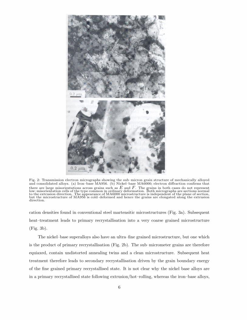
Fig. 2: Transmission electron micrographs showing the sub–micron grain structure of mechanically alloyedand consolidated alloys. (a) Iron–base MA956. (b) Nickel–base MA6000; electron diffraction confirms that
there are large misorientations across grains such as E and F . The grains in both cases do not representlow–misorientation cells of the type common in ordinary deformation. Both micrographs are sections normalto the extrusion direction. The appearance of MA6000 microstructure is independent of the plane of section,but the microstructure of MA956 is cold–deformed and hence the grains are elongated along the extrusiondirection.
cation densities found in conventional steel martensitic microstructures (Fig. 3a). Subsequent
heat–treatment leads to primary recrystallisation into a very coarse grained microstructure
(Fig. 3b).
The nickel–base superalloys also have an ultra–fine grained microstructure, but one which
is the product of primary recrystallisation (Fig. 2b). The sub–micrometer grains are therefore
equiaxed, contain undistorted annealing twins and a clean microstructure. Subsequent heat
treatment therefore leads to secondary recrystallisation driven by the grain boundary energy
of the fine grained primary recrystallised state. It is not clear why the nickel base alloys are
in a primary recrystallised state following extrusion/hot–rolling, whereas the iron–base alloys,
6
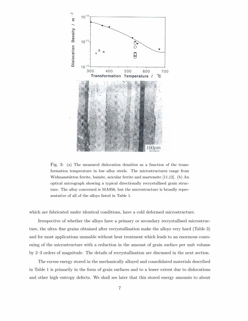
Fig. 3: (a) The measured dislocation densities as a function of the trans-
formation temperature in low–alloy steels. The microstructures range from
Widmanstatten ferrite, bainite, acicular ferrite and martensite [11,12]. (b) An
optical micrograph showing a typical directionally recrystallised grain struc-
ture. The alloy concerned is MA956, but the microstructure is broadly repre-
sentative of all of the alloys listed in Table 1.
which are fabricated under identical conditions, have a cold deformed microstructure.
Irrespective of whether the alloys have a primary or secondary recrystallised microstruc-
ture, the ultra–fine grains obtained after recrystallisation make the alloys very hard (Table 3)
and for most applications unusable without heat treatment which leads to an enormous coars-
ening of the microstructure with a reduction in the amount of grain surface per unit volume
by 2–3 orders of magnitude. The details of recrystallisation are discussed in the next section.
The excess energy stored in the mechanically alloyed and consolidated materials described
in Table 1 is primarily in the form of grain surfaces and to a lesser extent due to dislocations
and other high–entropy defects. We shall see later that this stored energy amounts to about
7
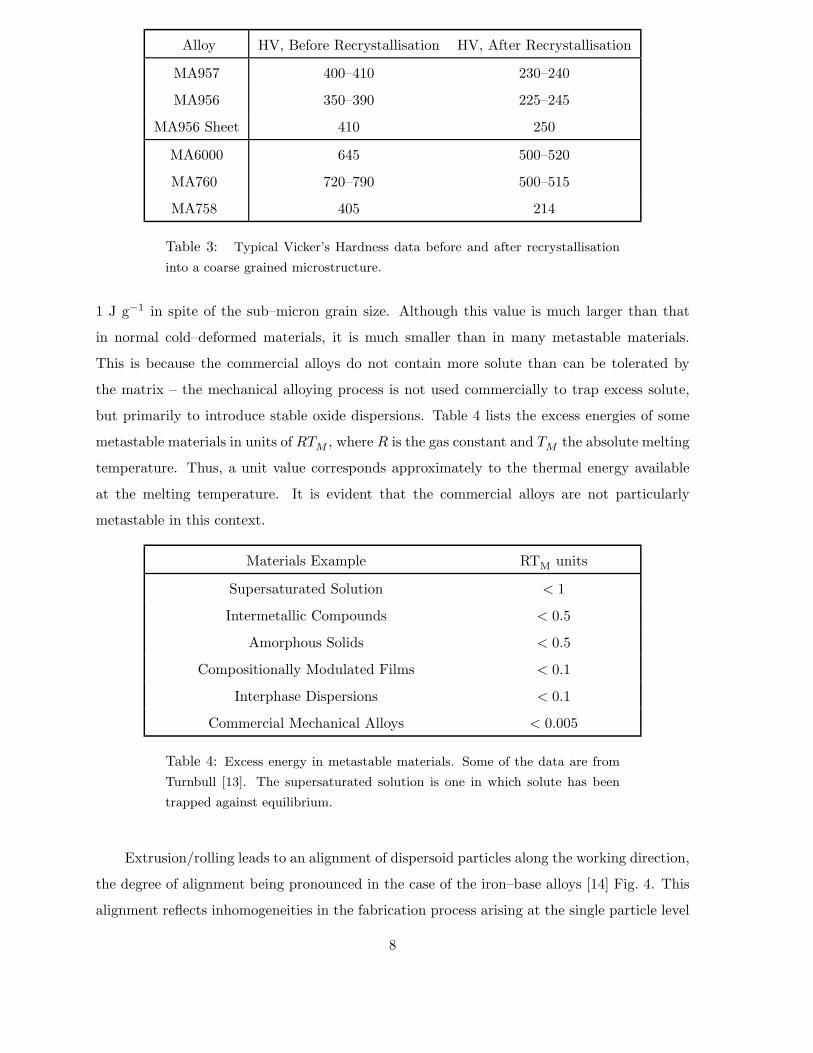
Alloy HV, Before Recrystallisation HV, After Recrystallisation
MA957 400–410 230–240
MA956 350–390 225–245
MA956 Sheet 410 250
MA6000 645 500–520
MA760 720–790 500–515
MA758 405 214
Table 3: Typical Vicker’s Hardness data before and after recrystallisation
into a coarse grained microstructure.
1 J g−1 in spite of the sub–micron grain size. Although this value is much larger than that
in normal cold–deformed materials, it is much smaller than in many metastable materials.
This is because the commercial alloys do not contain more solute than can be tolerated by
the matrix – the mechanical alloying process is not used commercially to trap excess solute,
but primarily to introduce stable oxide dispersions. Table 4 lists the excess energies of some
metastable materials in units of RTM , where R is the gas constant and TM the absolute melting
temperature. Thus, a unit value corresponds approximately to the thermal energy available
at the melting temperature. It is evident that the commercial alloys are not particularly
metastable in this context.
Materials Example RTM units
Supersaturated Solution < 1
Intermetallic Compounds < 0.5
Amorphous Solids < 0.5
Compositionally Modulated Films < 0.1
Interphase Dispersions < 0.1
Commercial Mechanical Alloys < 0.005
Table 4: Excess energy in metastable materials. Some of the data are from
Turnbull [13]. The supersaturated solution is one in which solute has been
trapped against equilibrium.
Extrusion/rolling leads to an alignment of dispersoid particles along the working direction,
the degree of alignment being pronounced in the case of the iron–base alloys [14] Fig. 4. This
alignment reflects inhomogeneities in the fabrication process arising at the single particle level
8
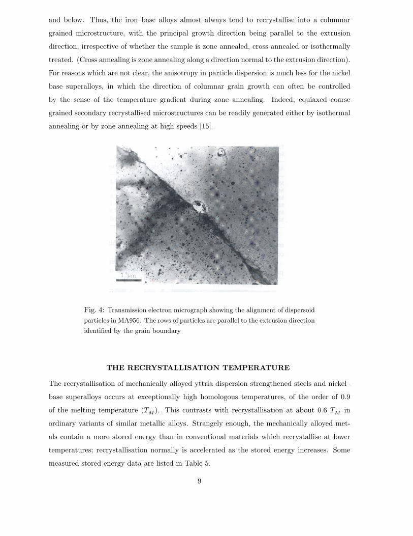
and below. Thus, the iron–base alloys almost always tend to recrystallise into a columnar
grained microstructure, with the principal growth direction being parallel to the extrusion
direction, irrespective of whether the sample is zone annealed, cross annealed or isothermally
treated. (Cross annealing is zone annealing along a direction normal to the extrusion direction).
For reasons which are not clear, the anisotropy in particle dispersion is much less for the nickel
base superalloys, in which the direction of columnar grain growth can often be controlled
by the sense of the temperature gradient during zone annealing. Indeed, equiaxed coarse
grained secondary recrystallised microstructures can be readily generated either by isothermal
annealing or by zone annealing at high speeds [15].
Fig. 4: Transmission electron micrograph showing the alignment of dispersoid
particles in MA956. The rows of particles are parallel to the extrusion direction
identified by the grain boundary
THE RECRYSTALLISATION TEMPERATURE
The recrystallisation of mechanically alloyed yttria dispersion strengthened steels and nickel–
base superalloys occurs at exceptionally high homologous temperatures, of the order of 0.9
of the melting temperature (TM ). This contrasts with recrystallisation at about 0.6 TM in
ordinary variants of similar metallic alloys. Strangely enough, the mechanically alloyed met-
als contain a more stored energy than in conventional materials which recrystallise at lower
temperatures; recrystallisation normally is accelerated as the stored energy increases. Some
measured stored energy data are listed in Table 5.
9
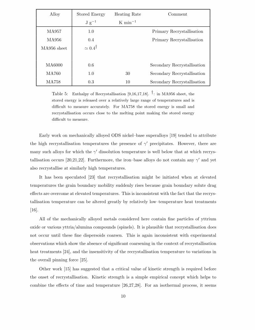
Alloy Stored Energy Heating Rate Comment
J g−1 K min−1
MA957 1.0 Primary Recrystallisation
MA956 0.4 Primary Recrystallisation
MA956 sheet � 0.4†
MA6000 0.6 Secondary Recrystallisation
MA760 1.0 30 Secondary Recrystallisation
MA758 0.3 10 Secondary Recrystallisation
Table 5: Enthalpy of Recrystallisation [9,16,17,18]. †: in MA956 sheet, the
stored energy is released over a relatively large range of temperatures and is
difficult to measure accurately. For MA758 the stored energy is small and
recrystallisation occurs close to the melting point making the stored energy
difficult to measure.
Early work on mechanically alloyed ODS nickel–base superalloys [19] tended to attribute
the high recrystallisation temperatures the presence of γ′ precipitates. However, there are
many such alloys for which the γ′ dissolution temperature is well below that at which recrys-
tallisation occurs [20,21,22]. Furthermore, the iron–base alloys do not contain any γ′ and yet
also recrystallise at similarly high temperatures.
It has been speculated [23] that recrystallisation might be initiated when at elevated
temperatures the grain boundary mobility suddenly rises because grain boundary solute drag
effects are overcome at elevated temperatures. This is inconsistent with the fact that the recrys-
tallisation temperature can be altered greatly by relatively low–temperature heat treatments
[16].
All of the mechanically alloyed metals considered here contain fine particles of yttrium
oxide or various yttria/alumina compounds (spinels). It is plausible that recrystallisation does
not occur until these fine dispersoids coarsen. This is again inconsistent with experimental
observations which show the absence of significant coarsening in the context of recrystallisation
heat treatments [24], and the insensitivity of the recrystallisation temperature to variations in
the overall pinning force [25].
Other work [15] has suggested that a critical value of kinetic strength is required before
the onset of recrystallisation. Kinetic strength is a simple empirical concept which helps to
combine the effects of time and temperature [26,27,28]. For an isothermal process, it seems
10
intuitively justified to assume that the effects of time and temperature can be rationalised by
taking the product:
t exp{−Q/kT} (1)
where t is the heat treatment time, Q is an activation energy and the other terms have their
usual meanings. This concept can be generalised to anisothermal heat treatments by taking
the integral: ∫exp{−Q/kT{t}} dt (2)
over the cycle of interest. Although the method has been successful within the limitations of
its empirical character, it fails to explain the unexpectedly high recrystallisation temperatures
in the mechanically alloyed metals. The activation energy Q needed in the kinetic strength
function, to rationalise available data on any particular alloy turns out to be some ten times
greater than that for the self diffusion of the base element.
More fundamental methods of analysing overall transformation kinetics are based on the
Johnson–Mehl–Avrami method, which can be developed to as much rigour as is necessary, or
as the need to know certain parameters permits. One simplification often used is to ignore
nucleation by assuming that a fixed number of nucleation sites exists at time zero. If this is
done for the mechanical alloys, then the experimental data are only well represented if the
activation energy for growth is made unrealistically large (again, some ten times that for the
self diffusion of the base element) [25,29].
These difficulties arise because when recrystallisation occurs at around 0.9 TM , it occurs
very rapidly during isothermal heat treatment, or over a very narrow temperature range during
continuous heating. Such data can only be represented by large activation energies in order to
achieve high recrystallisation temperatures and rapid subsequent transformation. However, to
assume that the activation energy for grain boundary motion is very much greater than that
for self–diffusion (QD) is unconvincing.
Almost all of these difficulties are resolved when nucleation is considered in detail [29,30].
It turns out that the activation energy for nucleation in the mechanical alloys should indeed
be very large. This is because the alloys have an unusually small grain size prior to recrystalli-
sation. The nucleation of recrystallisation occurs by the bowing of grain boundaries, a process
which for conventional alloys is straightforward since the distance between grain boundary
junctions is usually larger that between other strong pinning points. With the sub–micrometer
grain size of mechanically alloyed metals, the grain junctions themselves act as severe pinning
lines for grain boundary bowing (Fig. 5). It is easy to demonstrate that this should lead to an
11

enormous activation energy for the nucleation of recrystallisation, many orders of magnitude
larger than QD. It should be noted that Q in this model might be reduced if a few grains
happen to be slightly larger than others (either because adjacent grains are similarly orientated
or because of local variations due to the uncertainties in the mechanical alloying process).
Fig. 5: The nucleation of recrystallisation occurs by the formation of a grain
boundary bulge. This can occur with less constraint when the grain junctions
are spaced at distances greater than the critical bulge size. With the ultra–
fine grains of mechanically alloyed metals, the grain junctions are themselves
pinning points, making it very difficult to form large enough bulges.
This model for nucleation suggests a new concept, that individual grains cannot be con-
sidered to be topologically independent when the grain size becomes sufficiently small. It has
some remarkable consequences which have been verified experimentally:
(a) The model explains the high homologous recrystallisation temperatures irrespective of
alloy system. Recrystallisation is retarded whenever the grain size is small enough for the
grain junctions to act as pinning points during the formation of viable nuclei in the form
of grain boundary bulges.
(b) The model predicts that the recrystallisation temperature should decrease if the the stored
energy is reduced by a low–temperature heat treatment which leads to uniform grain
12
coarsening. This has now been verified experimentally for several alloys [16,29]. Since
recrystallisation should eventually become more difficult as the stored energy is reduced,
the curve of recrystallisation temperature versus grain size (or stored energy) should show
a minimum. This prediction has been verified experimentally [29].
ROLE OF CRYSTALLOGRAPHIC TEXTURE
Studies of the effect of the crystallographic texture in consolidated MA ODS alloys on their
recrystallisation behaviour have been confined to the iron–base alloys. There is conclusive
evidence that the recrystallisation temperature can be sensitive to the initial texture. A rea-
sonable explanation for this is that grain boundary mobility is affected by texture. During the
directional recrystallisation of ultra–fine grained MA ODS alloys, the recrystallised grains are
usually several hundreds of microns in width, and advance into a matrix with sub–micrometer
sized grains. Thus, the recrystallisation front in effect “sees” a tremendous variety of crystal-
lographic orientations and might be regarded as advancing into a liquid like structure. It then
is reasonable that samples in which the grains are oriented high mobility along the extrusion
direction, recrystallise more readily.
Crystallographic texture data suggest that when there is a preferred distribution of orienta-
tions, the major components of texture in the mechanically alloyed steels are {001} < 110 >,
{111} < 110 > [31,32], which belong to the so–called α and γ fibres in crystal orientation
distribution space. This applies in both the states, before and after recrystallisation, the re-
crystallisation process simply changing the strength of the texture components with respect
to a random distribution of orientations. For reasons which are not obvious, recrystallisation
seems easiest whenever the {111} < 110 > is prominent (Table 6). Thus, MA956 prior to
recrystallisation is rich in this particular component whereas MA957 is not, probably due to
the presence of austenite in MA957 at the fabrication temperature [16]. The former has a sub-
stantially lower recrystallisation temperature compared with the latter, even though MA957
has a relatively higher stored energy and lower yttria content than MA956. However, if MA957
is pre–annealed (i.e. heat–treated without recrystallisation) in order to make its texture com-
parable to that of MA956, then its recrystallisation temperature drops in spite of the reduction
in stored energy due to the preannealing heat–treatment.
Evens et al. [33] have also conducted microtextural measurements, and interpreted their
recrystallisation results in terms of the different mobilities of grain boundaries with different
orientations.
To summarise, there is no doubt that texture can influence the recrystallisation charac-
13

As–Received As–Received Preannealed
MA956 MA957 MA957
Stored Energy J g−1 0.4 1.00 0.70
Recrystallisation Start 1273 ◦C 1429 ◦C 1362 ◦C
Recrystallisation Finish 1334 ◦C 1447 ◦C 1382 ◦C
Texture Summary {111} < 110 > Random {111} < 110 >
{001} < 110 > Random {001} < 110 >
Recrystallised Grains Highly anisotropic anisotropic Equiaxed fine
Table 6: Recrystallisation characteristics of MA956 and MA957 in the as–
received condition [17]
teristics, but the mechanism remains unclear. There are many data in the literature which
show that the stored energy varies with the texture components, but those data are not rel-
evant in the present context because contrary to the results of conventional recrystallisation
experiments, the reduction in recrystallisation temperature is accompanied by a reduction in
stored energy. It could be argued that the particular component {111} < 110 > gives a higher
grain boundary mobility within a liquid–like matrix of ultra–fine grains, but this explanation
remains speculative.
THE DISPERSOIDS AND PRECIPITATES
Fine yttria particles (� 10 nm) are incorporated into the metallic matrix as a consequence of
the ball milling operations. Most of these survive as yttrium oxide in spite of consolidation
by extrusion and rolling at about 1050 ◦C. However, heat–treatment causes these particles to
react with dissolved aluminium (or titanium) and oxygen to produce a variety of compounds
[6,25,34,35]. The possible combinations of yttria and alumina include those listed in Table 7.
3Y2O3.5Al2O3 YAG yttrium aluminium garnet
Y2O3.Al2O3 YAH yttrium aluminium hexagonal
2Y2O3.Al2O3 YAM yttrium aluminium monoclinic
Y2O3.Al2O3 YAP yttrium aluminium perovskite
Y2O3.Al2O3 YAP’ yttrium aluminium pseudo–perovskite
3Y2O3.5Al2O3 YAT yttrium aluminite tetragonal
Table 7: Yttrium–Aluminium–Oxygen compound reported to occur in me-
chanically alloyed ODS iron and nickel base alloys.
14
140013001200110010
15
20
25
30
35
Alloy PM2010, annealed for 110 h
Annealing Temperature / C
Mea
n P
arti
cle
Siz
e /
nm
INITIAL SIZE
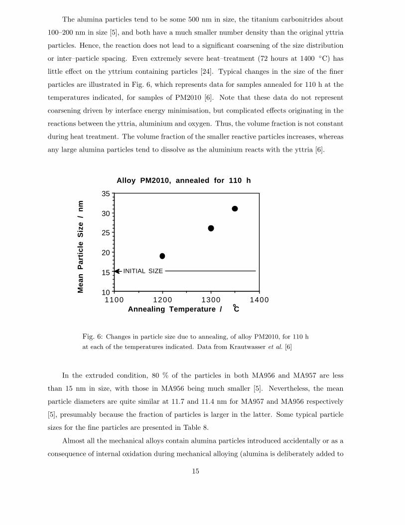
The alumina particles tend to be some 500 nm in size, the titanium carbonitrides about
100–200 nm in size [5], and both have a much smaller number density than the original yttria
particles. Hence, the reaction does not lead to a significant coarsening of the size distribution
or inter–particle spacing. Even extremely severe heat–treatment (72 hours at 1400 ◦C) has
little effect on the yttrium containing particles [24]. Typical changes in the size of the finer
particles are illustrated in Fig. 6, which represents data for samples annealed for 110 h at the
temperatures indicated, for samples of PM2010 [6]. Note that these data do not represent
coarsening driven by interface energy minimisation, but complicated effects originating in the
reactions between the yttria, aluminium and oxygen. Thus, the volume fraction is not constant
during heat treatment. The volume fraction of the smaller reactive particles increases, whereas
any large alumina particles tend to dissolve as the aluminium reacts with the yttria [6].
Fig. 6: Changes in particle size due to annealing, of alloy PM2010, for 110 h
at each of the temperatures indicated. Data from Krautwasser et al. [6]
In the extruded condition, 80 % of the particles in both MA956 and MA957 are less
than 15 nm in size, with those in MA956 being much smaller [5]. Nevertheless, the mean
particle diameters are quite similar at 11.7 and 11.4 nm for MA957 and MA956 respectively
[5], presumably because the fraction of particles is larger in the latter. Some typical particle
sizes for the fine particles are presented in Table 8.
Almost all the mechanical alloys contain alumina particles introduced accidentally or as a
consequence of internal oxidation during mechanical alloying (alumina is deliberately added to
15
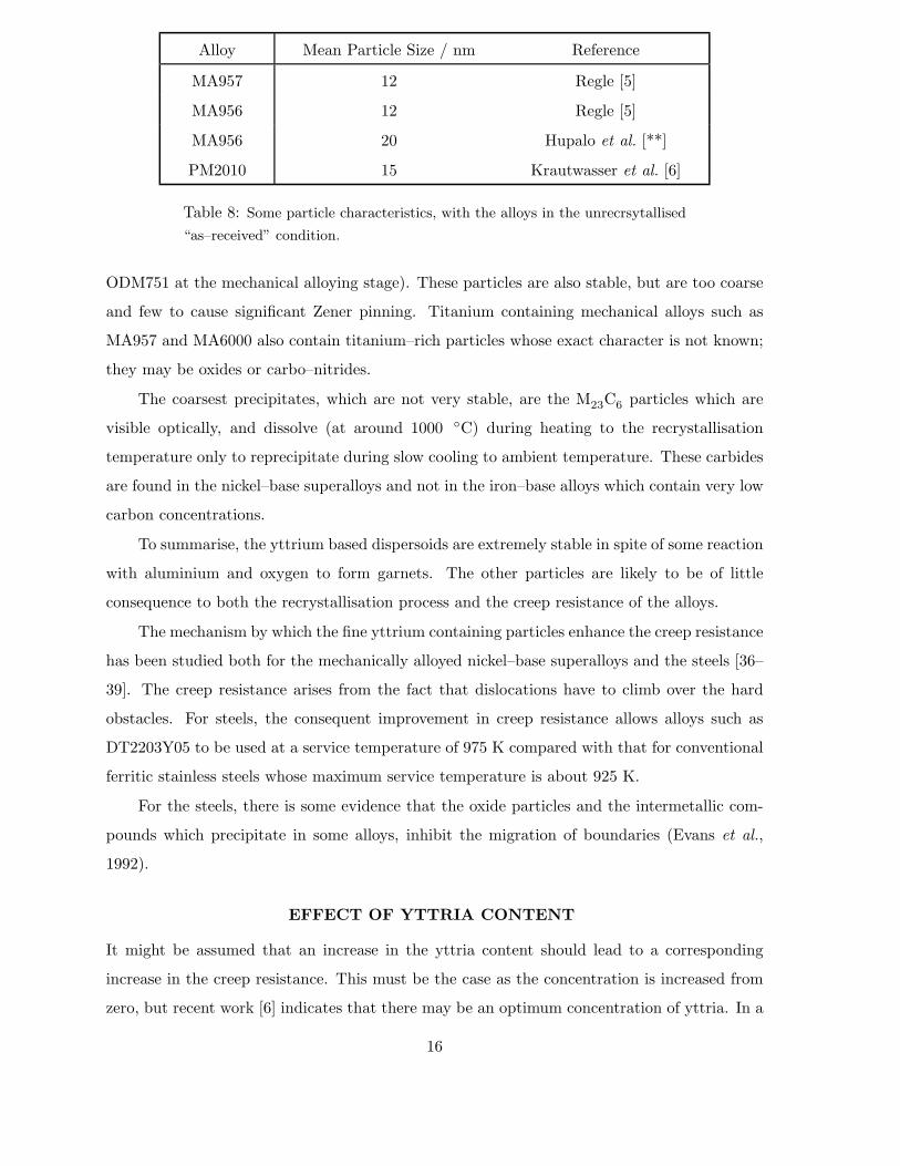
Alloy Mean Particle Size / nm Reference
MA957 12 Regle [5]
MA956 12 Regle [5]
MA956 20 Hupalo et al. [**]
PM2010 15 Krautwasser et al. [6]
Table 8: Some particle characteristics, with the alloys in the unrecrsytallised
“as–received” condition.
ODM751 at the mechanical alloying stage). These particles are also stable, but are too coarse
and few to cause significant Zener pinning. Titanium containing mechanical alloys such as
MA957 and MA6000 also contain titanium–rich particles whose exact character is not known;
they may be oxides or carbo–nitrides.
The coarsest precipitates, which are not very stable, are the M23C6 particles which are
visible optically, and dissolve (at around 1000 ◦C) during heating to the recrystallisation
temperature only to reprecipitate during slow cooling to ambient temperature. These carbides
are found in the nickel–base superalloys and not in the iron–base alloys which contain very low
carbon concentrations.
To summarise, the yttrium based dispersoids are extremely stable in spite of some reaction
with aluminium and oxygen to form garnets. The other particles are likely to be of little
consequence to both the recrystallisation process and the creep resistance of the alloys.
The mechanism by which the fine yttrium containing particles enhance the creep resistance
has been studied both for the mechanically alloyed nickel–base superalloys and the steels [36–
39]. The creep resistance arises from the fact that dislocations have to climb over the hard
obstacles. For steels, the consequent improvement in creep resistance allows alloys such as
DT2203Y05 to be used at a service temperature of 975 K compared with that for conventional
ferritic stainless steels whose maximum service temperature is about 925 K.
For the steels, there is some evidence that the oxide particles and the intermetallic com-
pounds which precipitate in some alloys, inhibit the migration of boundaries (Evans et al.,
1992).
EFFECT OF YTTRIA CONTENT
It might be assumed that an increase in the yttria content should lead to a corresponding
increase in the creep resistance. This must be the case as the concentration is increased from
zero, but recent work [6] indicates that there may be an optimum concentration of yttria. In a
16
series of experiments carried out on alloys PM2000 and PM2010, which differ only in the yttria
content (0.5, 1.0 wt.% respectively), it was found that the higher yttria content of PM2010
does not lead to a significantly larger number density of fine dispersoids (< 100 nm). It was
predicted therefore that PM2010 should not have a higher creep strength than PM2000 [6].
This result remains to be verified.
It also appears that in iron base alloys, yttria contents in excess of 0.5 wt.% cause a
deterioration in oxidation resistance because of a change in the morphology of the oxide [41].
THE GRAIN SHAPE
The major peculiar feature of the ODS mechanical alloys is that they tend to recrystallise into a
highly anisotropic columnar grain structure. There are two reasons why such grain structures
should arise. Zone annealing, like directional solidification can encourage growth along the
associated moving temperature gradient. Secondly, any dispersoids may tend to align along
the extrusion direction, so that the Zener pinning force is smallest for growth parallel to the
working direction, for both MA957 and MA956.
The nickel base alloys do not have a pronounced nonuniform distribution of dispersoids.
Thus, MA6000, when isothermally annealed, often recrystallises into an equiaxed grain struc-
ture (there are batch–to–batch variations). The same alloy will recrystallise directionally when
zone annealed. The sense of the columnar grains can be altered by changing the zone annealed
direction; cross annealing (i.e. zone annealing in a direction normal to the extrusion direction)
causes the growth of stubby columnar grains normal to the extrusion direction, confirming a
more or less uniform dispersoid distribution. In addition, zone annealing at high speeds leads
to a transition from a columnar to equiaxed recrystallised grains [15].
The nickel base alloy MA760 has a response which is similar to that of MA6000, although
the signs are that there is a stronger alignment of particles along the extrusion direction.
Thus, isothermal annealing does not lead to equiaxed grains, but cross annealing can change
the direction of the columnar recrystallised grains.
The mechanically alloyed steels contain a very pronounced alignment of particles along
the extrusion direction. Isothermal heat–treatment of as–worked samples always leads to the
development of coarse columnar grains. MA957, which has a rather low yttria content, has
relatively stubby columnar grains following isothermal heat treatment. No amount of cross
annealing or any other heat treatment has succeeded in causing a change in the direction of
columnar grain growth, which is always parallel to the working direction. The importance of
a nonuniform dispersion of particles in inducing the development of columnar grains has been
17
emphasized in recent experiments where the introduction of HfC or TiB2 led to the formation
of anisotropic grains during secondary recrystallisation of the NiAl intermetallic matrix [42].
The roughness of grain boundaries in recrystallised mechanically alloyed nickel–base su-
peralloys and steels has been characterised in detail [43–45]. The serrated boundaries arise
because of transient pinning by dispersoids. Coarser and smoother boundaries occur when
the stored energy is large, simply because it is then easier for the boundary to overcome the
pinning force [45].
PREANNEALING EFFECTS
Preannealing is a term used to describe a sample which has been heat treated at a temper-
ature which is too low for recrystallisation, but high enough to induce significant changes in
the stored energy, and in the subsequent microstructure following an elevated temperature
recrystallisation heat treatment.
The effects of preannealing, at temperatures above that at which austenite can form, on
MA957 can be summarised as follows [16]. A weak preannealing treatment (at about 1150 ◦C)
has little or no effect on subsequent recrystallisation. As the preannealing time is increased,
there is a transition from a coarse columnar grain structure to one which is equiaxed (20–
40µm) depending on the exact heat treatment). This is because the reduction in stored energy
reduces grain boundary mobility, so that nucleation has an opportunity to develop in several
regions of the sample, giving an equiaxed grain structure.
Continued preannealing causes the development of a bimodal equiaxed grain structure.
This is because there is an inhomogeneous distribution of pinning particles in the alloy. The now
substantial reduction in stored energy due to preannealing, retards recrystallisation more in
some regions compared with others which are less strongly pinned. For MA957 the preannealing
time at 1150 ◦C is in excess of 160 hours for this condition to be reached.
Further preannealing leads to such a large reduction in the stored energy that subsequent
recrystallisation is suppressed.
It is much more difficult to control the grain structure of MA956 using preannealing
heat treatments. Grain refinement certainly occurs, as in MA957, but the fine grains tend
not to be equiaxed. This may be because MA956 contains a larger concentration of yttria.
The anisotropic pinning due to the inhomogeneous distribution of the oxide particles is more
difficult to overcome if the fraction of particles is large. It would be very interesting to test
this with MA956 containing a smaller quantity of yttria dispersoids.
18
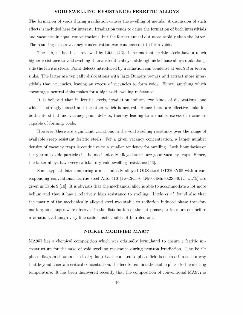
VOID SWELLING RESISTANCE: FERRITIC ALLOYS
The formation of voids during irradiation causes the swelling of metals. A discussion of such
effects is included here for interest. Irradiation tends to cause the formation of both interstitials
and vacancies in equal concentrations, but the former anneal out more rapidly than the latter.
The resulting excess vacancy concentration can condense out to form voids.
The subject has been reviewed by Little [46]. It seems that ferritic steels have a much
higher resistance to void swelling than austenitic alloys, although nickel base alloys rank along-
side the ferritic steels. Point defects introduced by irradiation can condense at neutral or biased
sinks. The latter are typically dislocations with large Burgers vectors and attract more inter-
stitials than vacancies, leaving an excess of vacancies to form voids. Hence, anything which
encourages neutral sinks makes for a high void swelling resistance.
It is believed that in ferritic steels, irradiation induces two kinds of dislocations, one
which is strongly biased and the other which is neutral. Hence there are effective sinks for
both interstitial and vacancy point defects, thereby leading to a smaller excess of vacancies
capable of forming voids.
However, there are significant variations in the void swelling resistance over the range of
available creep resistant ferritic steels. For a given vacancy concentration, a larger number
density of vacancy traps is conducive to a smaller tendency for swelling. Lath boundaries or
the yttrium oxide particles in the mechanically alloyed steels are good vacancy traps. Hence,
the latter alloys have very satisfactory void swelling resistance [46].
Some typical data comparing a mechanically alloyed ODS steel DT2203Y05 with a cor-
responding conventional ferritic steel AISI 410 (Fe–12Cr–0.4Ni–0.4Mn–0.2Si–0.1C wt.%) are
given in Table 9 [10]. It is obvious that the mechanical alloy is able to accommodate a lot more
helium and that it has a relatively high resistance to swelling. Little et al. found also that
the matrix of the mechanically alloyed steel was stable to radiation–induced phase transfor-
mation; no changes were observed in the distribution of the chi–phase particles present before
irradiation, although very fine scale effects could not be ruled out.
NICKEL MODIFIED MA957
MA957 has a chemical composition which was originally formulated to ensure a ferritic mi-
crostructure for the sake of void swelling resistance during neutron irradiation. The Fe–Cr
phase diagram shows a classical γ–loop i.e. the austenite phase field is enclosed in such a way
that beyond a certain critical concentration, the ferrite remains the stable phase to the melting
temperature. It has been discovered recently that the composition of conventional MA957 is
19
Alloy Cavity Cavity Cavity Dislocation
Concentration Diameter Swelling Density
/ 1021 m−3 / nm % / 1014 m−2
DT2203Y05 8.0 8.3 0.24 9.7
AISI 410 19.8 6.0 0.49 8.9
Table 9: Results of experiments in which the samples were irradiated with
chromium ions and α particles to a total displacement dose of 50 dpa and
a helium content of 600 appm [10]. The alloy DT2203Y05 was induction
annealed at 1050 ◦C for 3 minutes, followed by ageing at 800 ◦C for 24 hours.
It is not clear whether this heat treatment is sufficient to give a recrystallised
microstructure.
such that it just clips the γ–loop at around 1000 ◦C, so that it is possible with suitable heat
treatment to obtain a few percent of austenite [16].
Calculations have demonstrated that the addition of just 12 wt.% of nickel to the conven-
tional alloy can raise the maximum austenite volume fraction to 0.5. Thus, a transformable
mechanically alloyed steel, “MA957Ni” should be possible without any major changes in alloy
chemistry.
Such alloys have now been made [47] and have confirmed the phase stability calculations.
In fact, a series of four experimental alloys are available with a maximum austenite fraction
from 0-1. The transformations have been detected experimentally. The possibility of generating
a variety of microstructures by transformation has also been demonstrated.
COLD DEFORMATION
Regle and Alamo [48] have conducted extensive studies on the recrystallisation behaviour of
MA956 and MA957, for samples which were cold deformed after extrusion. Two deformation
processes were used, swaging and drawing, with reductions ranging from 10 → 60%.
Swaging and drawing led to quite different changes in crystallographic texture, and indeed
to the subsequent recrystallisation behaviour. In all cases, deformation led to a reduction in
the recrystallisation temperature, the change being largest for the cold–drawn samples. For
MA957, the maximum reduction in the recrystallisation temperature was found to be about 200◦C from 1450 → 1250 ◦C. The corresponding maximum reduction for MA956 was for the cold
drawn samples, where the recrystallisation temperature could be reduced from 1350 → 750 ◦C.
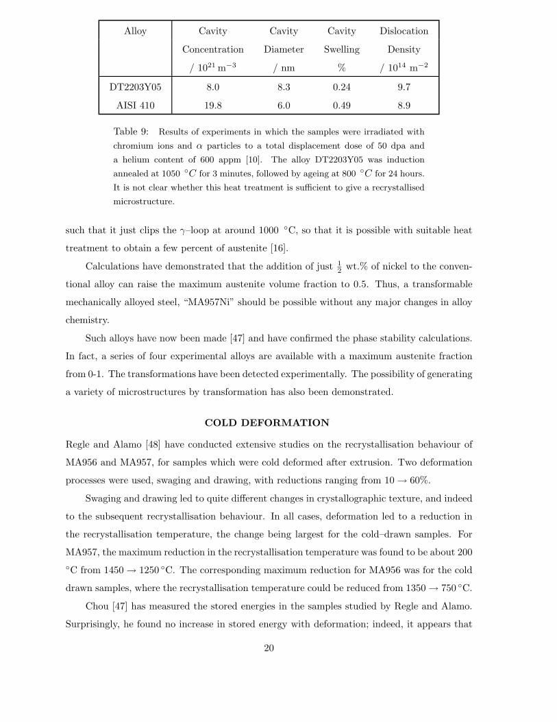
Chou [47] has measured the stored energies in the samples studied by Regle and Alamo.
Surprisingly, he found no increase in stored energy with deformation; indeed, it appears that
20
MA957 Recrystallisation Recrystallisation Stored Energy
Start, ◦C Finish, ◦C J g−1
0% drawn 1370 1412 0.93
30% drawn 1018 1093 0.78
40% drawn 998 1056 0.70
50% drawn 989 1041 0.69
60% drawn 980 1027 0.65
Table 10: Cold drawn MA957. DSC measurements at 20 K min−1 (after
Chou, unpublished research)
the deformation leads to a reduction in stored energy (Table 10).
There is no clear explanation of the results, but it is possible that the cold deformation
modifies the crystallographic texture. It is conceivable that the texture change both leads to
a reduction in the stored energy, and at the same time, a reduction in the recrystallisation
temperature. The texture could, for example, lead to the clustering of adjacent grains into
similar orientations. This would lead to an increase in the effective grain size, thereby making
the nucleation of recrystallisation more easy.
There are some other elegant results presented by Regle and Alamo, which are consistent
with this interpretation. A sample which was necked by deformation (and hence contained
a controlled deformation gradient), was subjected to a recrystallisation heat treatment. It
was vividly demonstrated that the anisotropic recrystallisation grain structure became refined
with the extent of deformation. This is in spite of the fact that the stored energy actually
decreased. Thus, deformation must enhance the nucleation rate of recrystallisation, perhaps
by the texture mechanism discussed above.
TRANSFORMATION PLASTICITY
Phase transformation under the influence of an external stress can cause plasticity. This
non–recoverable strain is not to be confused with creep; transformation plasticity can occur at
temperatures and in time–scales which are wholly inconsistent with the generation of detectable
creep strains.
MA957 is, within a restricted temperature range, able to transform to a few percent of
austenite. However, modifications of MA957 which are able to transform to a much greater
extent, are found to be much more susceptible to transformation–induced plasticity [49]. Ap-
plications in which these modified alloys undergo cyclic transformation under the influence of
21
stress are unlikely to be reliable.
NONUNIFORM RECRYSTALLISATION
Most of the work in this area is on the nickel–base superalloy MA6000 [18]. It is found that
there are profound differences across the cross section of the extruded bar, the edge regions
recrystallising more easily relative to the core regions. The recrystallised grains tend to be
have much larger aspect ratios at the edges. It appears that these differences are caused by
inhomogeneous deformation. The oxide particles are more aligned along the extrusion direction
at the regions near the surface, presumably because of the more extensive deformation in those
regions. This alignment explains the greater anisotropy in the recrystallised grains and the
relative ease of recrystallisation. The boundary mobility along the extrusion direction is larger
when the particles are aligned. Stored energy measurements confirm that the observed effects
cannot be explained by differences in the driving force for recrystallisation.
Martin [50] has discussed this work by presenting a calculation which indicates that the
yttria particles, because of their small size, are not amenable to alignment by extrusion. How-
ever, Murakami et al. [51] have pointed out that his analysis assumes that the starting powder
stock is uniform. This is not the case in practice. Mechanical alloying is a difficult process,
and there are composition variations between powder particles/aggregates, which develop into
banded regions as a consequence of extrusion. Results confirming the fact the mechanical al-
loying process can produce dispersoid inhomogeneities, which are carried through to the final
product have recently been published by Jaeger and Jones [52,53] for alloys ODM 331 and
ODM 751, both of which are iron based. This study is particularly useful in that the materials
were examined both before and after consolidation. When a powder which is inhomogeneous in
its dispersoid distribution is fabricated into a tube form, the particles align in concentric cylin-
ders parallel to the tube axis. This in turn leads to an onion–peel type of recrystallised grain
structure [53], which may be of some benefit from the point of view of mechanical properties.
It is strange that such inhomogeneities are most pronounced with the iron base alloys but
not with the nickel base materials where the extent of particle alignment along the extrusion
direction is usually minimal [16].
Finally, it is well established that both the manufacture of mechanically alloyed powder
and the subsequent consolidation are both imperfect processes and lead to inhomogeneities in
the final product. Fragments of improperly alloyed particles can be retained in the product,
and act as defects [54]. If improperly bonded, they can act as cavities, or indeed as pinning
centres for the advancing recrystallisation front.
22
MA956 SHEET
MA956 sheet has the same composition as its rod form, but is made by a different route.
After consolidating the mechanically alloyed powder by hot isostatic pressing, the billets are
hot rolled with a reduction of approximately 98% to a thickness of 2.1 cm [55]. The rolling is
carried out in the temperature range 1025–1065 ◦C.
The sheet is often cold deformed (typically another 60% reduction in thickness) before a
recrystallisation heat treatment at about 1340 ◦C. The recrystallisation then begins at the
centre of the sheet – in fact, the central regions tend to recrystallise completely before the
surface regions [55]. The reason for such behaviour is not understood.
The crystallographic texture after the hot–deformation is {100} < 011 >, a texture which
is sharpened by deformation at ambient temperatures [55].
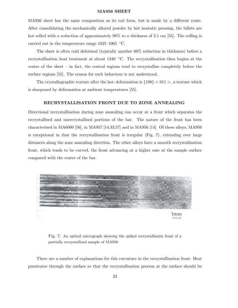
RECRYSTALLISATION FRONT DUE TO ZONE ANNEALING
Directional recrystallisation during zone annealing can occur at a front which separates the
recrystallised and unrecrystallised portions of the bar. The nature of the front has been
characterised in MA6000 [56], in MA957 [14,33,57] and in MA956 [14]. Of these alloys, MA956
is exceptional in that the recrystallisation front is irregular (Fig. 7), extending over large
distances along the zone annealing direction. The other alloys have a smooth recrystallisation
front, which tends to be curved, the front advancing at a higher rate at the sample surface
compared with the centre of the bar.
Fig. 7: An optical micrograph showing the spiked recrystallisatin front of a
partially recrystallised sample of MA956
There are a number of explanations for this curvature in the recrystallisation front. Heat
penetrates through the surface so that the recrystallisation process at the surface should be
23
at a more advanced stage relative to the central regions. Miodownik et al. [57] carried out an
experiment in which a partially zone annealed sample was subsequently held in a stationary
temperature gradient for thirty minutes. Since the recrystallisation front remained curved,
they claimed that the curvature cannot be explained by temperature gradients normal to the
zone annealing axis. However, the degree of curvature in fact decreased on holding the sample
in the stationary temperature gradient. The possibility therefore remains that temperature
variations across the cross section of the bar are to some extent responsible for the curvature
in the recrystallisation front.
In the specific case of a nickel–base superalloy MA6000, Murakami et al. [18] have shown
that the extrusion process leads to a greater degree of dispersoid alignment in the surface
regions of the bar, and that this leads to a greater ease of recrystallisation in those regions.
This could also explain the curved recrystallisation front. By contrast, Marsh and Martin [56]
ascribed the curved front to the existence of strain (and corresponding texture) gradients in
the MA6000 bar. It is worth noting that although it is likely that the extrusion process leads
to a greater degree of deformation in the surface regions, the stored energy of the MA6000
does not vary significantly across the cross–section [18] because the sample is in the primary
recrystallised state before zone annealing.
Evens et al. [33] have suggested that in MA957, the curved recrystallisation front is a
consequence of gradients in solute concentration, which influence grain boundary mobility. In
support of this idea, Miodownik et al. [57] showed a peak in the concentration of titanium
at a grain boundary in an extruded and heat treated bar of MA957. An experiment like this
needs to be repeated on an unrecrystallised sample, since it is solute segregation in that state
which needs to be characterised, rather than at boundaries between the coarse directionally
recrystallised grain boundaries.
COMPOSITE ALLOYS
Since MA956 is so heavily alloyed with aluminium and chromium, its ferritic matrix remains
stable until the melting temperature. It is therefore not possible to control its grain structure
using the γ → δ transformation. A feasible alternative could be to introduce a fraction of
transformable material within the powder compact of MA956 before it is extruded. This
amounts to making the alloy chemically inhomogeneous, a metallic composite dubbed MeMeC
(metal–metal–composite). The transformable part can in principle help control the grain
structure of the residue which does not transform.
Work in this area is in its early stages, but initial results show that it is possible to obtain
24
fine grained microstructures in MA956–20% MA957Ni composites.
SUMMARY
Recrystallisation in MA–ODS iron and nickel–base alloys is dominated by the ultra–fine
grain structure which is a consequence of the mechanical alloying and consolidation process,
and by the presence of dispersoids. The grain structure can be so fine that the grain junctions
themselves act to hinder the initiation of recrystallisation. Such fine grains cannot be consid-
ered to be topologically independent in this context. The dispersoids are mainly responsible
for the anisotropy in the recrystallisation microstructure.
In general, the microstructure of these alloys is well–characterised and understood. It is
necessary now to gain an equal understanding of the mechanical properties of such alloys.
25

ACKNOWLEDGMENTS
The author is grateful to Professor A. H. Windle for the provision of laboratory facilities
at the University of Cambridge and to Dr. David Gooch for commenting on several drafts of
the paper. I am also grateful to H. Harada, G. Hack, J. O’Driscoll, L. Patel, J. O’Driscoll,
T. Chou, K. Murakami, K. Mino, A. Badmos and W. Sha for many helpful discussions. Some
of this work was carried out under the auspices of the “Atomic Arrangements: Design and
Control Project”, which is a collaborative effort between the University of Cambridge and the
Research and Development Corporation of Japan. The work was also supported by National
Power plc. and the Engineering and Physical Sciences Research Council.
REFERENCES
1. J. S. Benjamin and P. S. Gilman: Metals Handbook, ninth edition, ASM International, Ohio7 (1983) 722.
2. G. H. Gessinger: Powder Metallurgy of Superalloys, Butterworth and Co., London. (1984)3. G. A. J. Hack: Powder Metallurgy 27 (1984) 73–79.4. J. S. Benjamin: Metall. Trans. 1 (1970) 2943–2951.5. H. Regle: Ph.D. Thesis, “Alliages Ferritiques 14/20% de chrome Renforces par Dispersion
d’Oxydes”, Universite de Paris–Sud. (1994)6. P. Krautwasser, A. Czyrska–Filemonowic, M. Widera and F. Carsughi: Materials Science
and Engineering A A177 (1994) 199–208.7. B. Kazimierzak, M. Prignon, C. Lecomte–Mertens and C. Coutsouradis: High Temperature
Materials for Power Engineering 1990, Kluwer Academic Publishers, (1990) 131, quotedby Regle (1994).
8. L. Patel: Private Communication, to H. K. D. H. Bhadeshia, University of Cambridge, U.K. (1994)
9. W. Sha and H. K. D. H. Bhadeshia: Metallurgical and Materials Transactions A 25A (1994)705–714.
10. E. A. Little, D. J. Mazey and W. Hanks: Scripta Metall. Mater. 25 (1991) 1115–1118.11. M. Takahashi and H. K. D. H. Bhadeshia: Materials Science and Technology 6 (1990)
592–603.12. H. K. D. H. Bhadeshia: Mathematical Modelling of Weld Phenomena III, eds H. Cerjak
and H. K. D. H. Bhadeshia, Institute of Materials, London (1996) in press.13. D. Turnbull: Metall. Trans. A 12A (1981) 695–708.14. M. Baloch: Ph.D. Thesis, University of Cambridge. (1989)15. M. Baloch and H. K. D. H. Bhadeshia: Materials Science and Technology 6 (1991) 1236–
1246.16. T. S. Chou and H. K. D. H. Bhadeshia: Materials Science and Technology 9 (1993)
890–897.17. T. S. Chou and H. K. D. H. Bhadeshia: Materials Science and Engineering A A189 (1994)
229–233.18. K. Murakami, K. Mino, H. Harada and H. K. D. H. Bhadeshia: Metall. Trans. A 24A
(1993) 1049–1055.
26
19. Y. G. Nakagawa, H. Terashima and K. Mino: Superalloys 1988, eds S. Reichman, D.N. Duhl, G. Maurer, S. Antolovich and C. Lund, TMS–AIME, Warrendale, PA, U.S.A.(1988) 81–89.
20. K. Mino, Y. G. Nagakawa and A. Ohtomo: Metall. Trans. A 18A (1987) 777.21. K. Kusunoki, K. Sumino, Y. Kawasaki and M. Yamazaki: Metall. Trans. A 21A (1990)
547.22. K. Mino, H. Harada, H. K. D. H. Bhadeshia and M. Yamazaki: Materials Science Forum
88–90 (1992) 213–220.23. P. Jongenburger: Ph.D. Thesis no. 773, Ecole Polytechnique Federale de Lausanne,
Switzerland (1988)24. A. P. Backhouse, S. S. Babu, K. Mino and H. K. D. H. Bhadeshia: Pt. II Project Report,
Cambridge University. (1991)25. K. Murakami: Ph.D. Thesis, Cambridge University. (1993)26. J. H. Holloman and L. D. Jafee: Trans. AIME 162 (1945) 223–249.27. P. J. Alberry and W. K. C. Jones: Metals Technology 4 (1977) 557–566.28. M. F. Ashby and K. E. Easterling: Acta Metall. 30 (1982) 1969–1978.29. W. Sha and H. K. D. H. Bhadeshia: Materials Science and Engineering A (1996) these
proceedings.30. K. Murakami and H. K. D. H. Bhadeshia: Unpublished research, Cambridge University.
(1993)31. A. Alamo, H. Regle and J. L. Bechade: Novel Powder Processing, Advances in Powder Met-
allurgy and Particulate Materials – 1992, Metal Powder Industries Federation, Princeton,NJ, USA 7 (1992) 169–182.
32. T. S. Chou and H. K. D. H. Bhadeshia: Metall. Trans. A 24A (1993) 773–779.33. P. J. Evens, J. W. Martin and E. A. Little: Materials Science and Technology 8 (1992)
531–536.34. G. B. Schaffer, M. H. Loretto, R. E. Smallman and J. W. Brooks: Acta Metall. 37 (1989)
2551–2558.35. H. Cama and T. A. Hughes: Institute of Physics Conference Series No. 138: Section 7,
EMAG93, ed. A. Craven, IOP Publishing, Oxford, U. K. (1993) 361–364.36. V. C. Nardone and J. K. Tien: Scripta Metallurgica 17 (1983) 467.37. R. S. Herrick, J. R. Weertman, R. Petkovic–Luton, and M. J. Luton: Scripta Metallurgica
22 (1988) 1879.38. J. H. Schroder and E. Arzt: Scripta Metallurgica 19 (1985) 1179.39. J. Preston, B. Wilshire and E. A. Little: Scripta Metall. Mater. 25 (1991) 183–184.40. R. W. Evans, J. Preston, B. Wilshire and E. A. Little: J. of Nuclear Materials 195 (1992)
24–28.41. H. Nickel and W. J. Quadakkers: Heat Resistant Materials eds. K. Natesan and D. J.
Tillack, Fontana, WI, Sept. 1991, ASM International (1991) 87.42. I.–G. Lee, A. K. Ghosh, R. Ray and S. Jha: Metallurgical and Materials Transactions 25A
(1994) 2017–2026.43. D. L. Whittenberger: Metallurgical Transactions A 12A (1981) 845.44. D. M. Jaeger and A. R. Jones: Materials for Combined Cycle Power Plant, Institute of
Metals, London (1991) 1–11.45. K. Murakami, H. Harada and H. K. D. H. Bhadeshia: Heat Treatment ’92, ed. I. Tamura,
Kyoto, Japan (1992) 269–272.46. E. A. Little: Materials Modelling: From Theory to Technology, IOP Publishing, Oxford
(1991) 141–146.
27
47. T. S. Chou: Ph.D. Thesis, University of Cambridge. (1994)48. H. Regle and A. Alamo: Journal de Physiqe IV 3, C7 (1993) 727–73049. S. Suzuki and H. K. D. H. Bhadeshia: Unpublished research, Cambridge University. (1993)50. J. W. Martin: Metallurgical Transactions A 25A (1994) 651–652.51. K. Murakami, K. Mino, H. Harada and H. K. D. H. Bhadeshia: Metall. Trans. A 25A
(1994) 652–653.52. D. M. Jaeger and A. R. Jones: Materials for Advanced Power Engineering, “Dispersoid dis-
tributions in iron based ODS alloys made by mechanical alloying”, Leige, Belgium (1994)in press.
53. D. M. Jaeger and A. R. Jones: Materials for Advanced Power Engineering, “The develop-ment of grain shape in iron base ODS alloys”, Leige, Belgium (1994) in press.
54. D. M. Jaeger and A. R. Jones: Processing, Properties and Applications of Metallic andCeramic Materials, eds. M. H. Loretto and G. J. Beevers, Birmingham, U. K. (1992) 1–6.
55. R. C. Klug, G. Krauss and D. K. Matlock: Hot Deformation Textures and Microstructures,TMS Fall Meeting, November 1993, Pittsburgh, PA, unpublished research. (1993)
56. J. M. Marsh and J. W. Martin: Materials Science and Technology 7 (1991) 183.57. M. A. Miodownik, J. W. Martin and E. A. Little: Journal of Materials Science Letters 12
(1993) 834–835.. Y. Ikeda, H. Sumiyoshi and Y. Ishiwata: ISIJ International 35 (1995) 1109–1114.. Y. Kawasaki, Y. Ikeda, T. Kobayashi and H. Sumiyoshi: ISIJ International 36 (1996) 1208–
1214.. M. F. Hupalo, M. Terada, A. M. Kliauga and A. F. Padilha: Mat.–wiss. u. Werkstofftech.
34 (2003) 505–508.
28