RECORDING AND CODING GUIDE FOR STRUCTURE INVENTORY AND ... · recording and coding guide for...
421
RECORDING AND CODING GUIDE FOR STRUCTURE INVENTORY AND APPRAISAL OF NEW JERSEY BRIDGES STRUCTURAL EVALUATION 2003
Transcript of RECORDING AND CODING GUIDE FOR STRUCTURE INVENTORY AND ... · recording and coding guide for...

RECORDING AND CODING GUIDE FOR
STRUCTURE INVENTORY AND APPRAISAL
OF NEW JERSEY BRIDGES
STRUCTURAL EVALUATION 2003
BUREAU OF STRUCTURAL ENGINEERING This printing include the contents of the 1995 Federal “Recording and Coding Guide for the Structure Inventory and Appraisal of the Nation’s Bridges” and the 2003 State “Recording and Coding Guide for the Structure Inventory and Appraisal of New Jersey Bridges”. Also, the 2003 State “Railroad Bridge Coding Instructions” are included. This printing is available by accessing the Department of Transportation website. Additional copies of this Manual may be printed from this source. If, for any reason you cannot access the aforementioned website, additional copies of this Manual are available upon written request: New Jersey Department of Transportation Bureau of Structural Engineering 1035 Parkway Avenue CN 600 Trenton, New Jersey 08625


NEW JERSEY DEPARTMENT OF TRANSPORTATION MEMORANDUM
TO: All Bridge Inspection Staff, Structural Evaluation FROM: James Lane, Manager Structural Evaluation DATE: February 5, 2007 PHONE: 5-3572 SUBJECT: Revision to the 2003 Recording and Coding Guide for the Structure Inventory and Appraisal of New Jersey Bridges ________________________________________________________________________________ The following revisions to the subject Manual have been made for the reasons specified below: Page F11 Item 19 – Bypass, Detour Length: Revision is necessary to correct typographical
error. See revision in Red. Page F32 Item 49 – Structure Length: Revision is necessary to correct typographical error. See
revision in Red. Page F37 Item 51 – Bridge Roadway Width: Revision is necessary to correct typographical
error. See revision in Red. Page F42 Item 56 – Minimum Lateral Underclearance on Left: Revision is necessary to correct
typographical error. See revision in Red. Page F53 Item 68 – Deck Geometry: Typographical error in Table 2A. The proper value for
code ‘7’ for ADT between ‘2001 to 5000’ and ‘>5000’ should be ‘= 44’ rather than ‘>44’.
Page F61 Item 72 – Approach Roadway Alignment: Revision is necessary to correct
typographical error. See revision in Red. Page S-7 Item A- Town: Revision is necessary due to the Dover Township changing it’s name
to Toms River Township. Page S-27 BC – USRA Line Code: Revision is necessary to correct typographical error. See
revision in Red. Page S-46 Item FQ – Last In-Depth Fracture Critical/Pin-Hanger Inspection Date: Revision is
necessary to correct the name of the Item. It should read ‘Latest In-Depth Fracture Critical/Pin-Hanger Inspection Date’. Also, it should be coded ‘MM, DD, YYYY’.

Page 2 Revision to the 2003 Recording and Coding Guide for the Structure Inventory and Appraisal of New Jersey Bridges Page S-48 Item GC – Date of Paint Inspection: Revision is necessary to correct typographical
error. See revision in Red Page S-49 Items GD Thru GO – Paint Condition Rating: Revisions are necessary to avoid
duplication code. Page SF-4 TL-5 Bridge Railing: Revision is necessary to give more clarification for TL-5 Bridge
Railing. Only interstate highways carrying Bridge required TL-5 Bridge Railing (not on freeway).
Pages SF-4, SF-5, SF-6, SF-7, SF-17, SF-25, SF-27 AND SF-28: These pages are revised based on Baseline Document changes that have been released
as follows: BDC03D-04 dated on 03/10/2004 BDC06S-07 dated on 12/11/2006 Federal—Appendix C: Revised to incorporate the version of the regulations effective January 13, 2005 c: Richard W. Dunne Helene Bowman

ITEM 17 - LONGITUDE (CONTINUED) The reason for the increased precision is to facilitate the use of Global Positioning System (GPS) data directly into this item. The increased precision is not currently mandatory and, if GPS readings are not available, the current measuring methods and level of precision may continue to be used. The minimum precision should be to the nearest minute, but the preferred precision is to the nearest hundredth of a second using GPS methods. Example: Code Longitude is 81°5.8' (current precision) 081054800 (acceptable coding) 081060000 81°5'50.65" (GPS reading) 081055065 ITEM 18 (reserved) ITEM 19 - BYPASS, DETOUR LENGTH (XX miles) 2 DIGITS Indicate the actual length to the nearest mile of the detour length. The detour length should represent the total additional travel for a vehicle which would result from closing of the bridge. The factor to consider when determining if a bypass is available at the site is the potential for moving vehicles, including military vehicles, around the structure. This is particularly true when the structure is in an interchange. For instance, a bypass likely would be available in the case of diamond interchanges, interchanges where there are service roads available, or other interchanges where the positioning and layout of the ramps is such that they could be used without difficulty to get around the structure. If a ground level bypass is available at the structure site for the inventory route, record and code the detour length as 00. If the bridge is one of twin bridges and is not at an interchange, code 01 where the other twin bridge can be used as a temporary bypass with a reasonable amount of crossover grading. The detour route will be established following allowable criteria determined by the governing authority. (Some authorities will not allow a designated detour over a road or bridge of lesser "quality.") Code 99 for 99 miles or more.
F11

ITEM 48 - LENGTH OF MAXIMUM SPAN (XXXX feet) 4 DIGITS The length of the maximum span shall be recorded. It shall be noted whether the measurement is center to center of bearing points or clear open distance between piers, bents, or abutments. The measurement shall be along the centerline of the bridge. For this item, code a 4-digit number to represent the measurement to the nearest foot. Examples: Code Length of Maximum Span 50 feet 0050 117 feet 0117 1,050 feet 1050 ITEM 49 - STRUCTURE LENGTH (XXXXXX feet) 6 DIGITS Record and code a 6-digit number to represent the length of the structure to the nearest foot. This shall be the length of roadway which is supported on the bridge structure. The length should be measured back to back of backs walls of abutments or from paving notch to paving notch. Culvert lengths should be measured along the center line of roadway regardless of their depth below grade. Measurement should be made between inside faces of exterior walls. Tunnel length should be measured along the centerline of roadway. Be sure to code Item 5A = 2 for all tunnels. Examples: Structure Length Code 50 feet 000050 5,421 feet 005421 333 feet 000333 101,235 feet 101235
F32
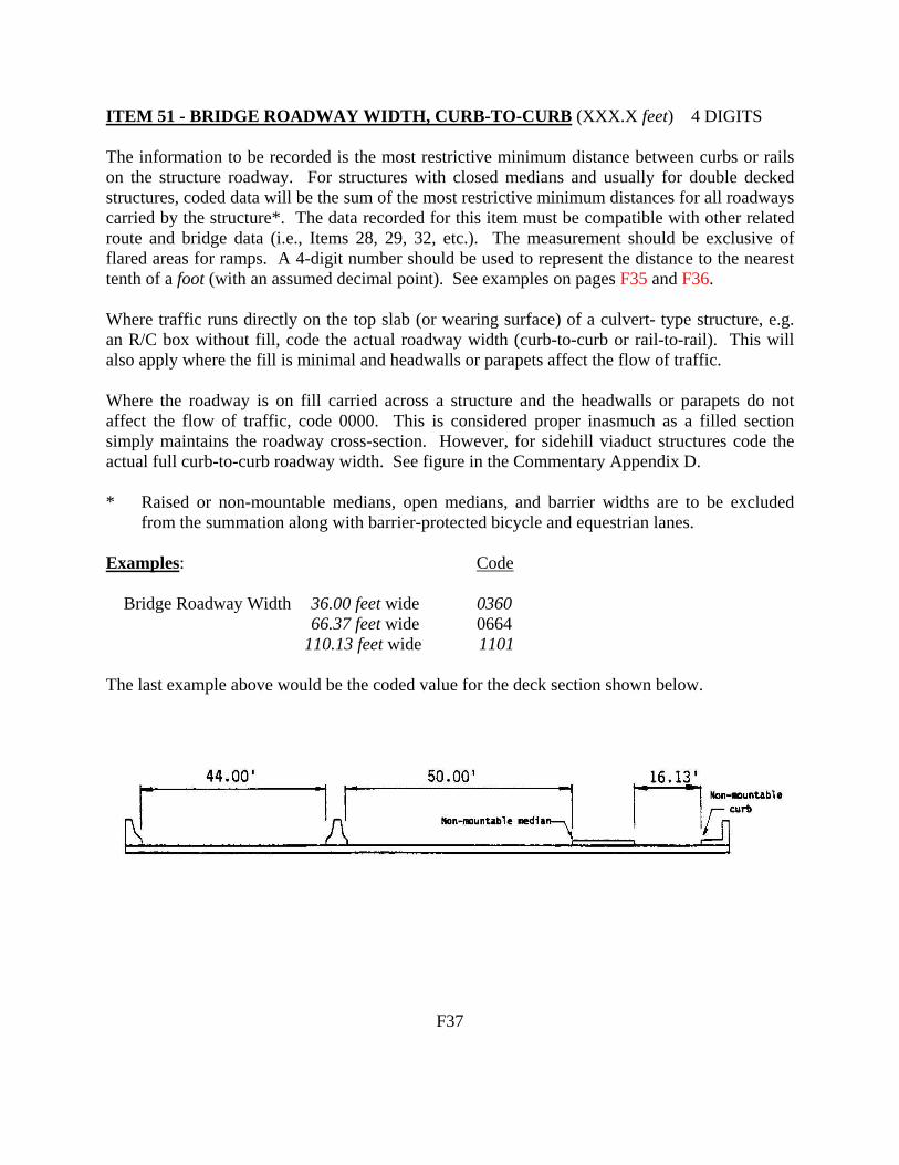
ITEM 51 - BRIDGE ROADWAY WIDTH, CURB-TO-CURB (XXX.X feet) 4 DIGITS The information to be recorded is the most restrictive minimum distance between curbs or rails on the structure roadway. For structures with closed medians and usually for double decked structures, coded data will be the sum of the most restrictive minimum distances for all roadways carried by the structure*. The data recorded for this item must be compatible with other related route and bridge data (i.e., Items 28, 29, 32, etc.). The measurement should be exclusive of flared areas for ramps. A 4-digit number should be used to represent the distance to the nearest tenth of a foot (with an assumed decimal point). See examples on pages F35 and F36. Where traffic runs directly on the top slab (or wearing surface) of a culvert- type structure, e.g. an R/C box without fill, code the actual roadway width (curb-to-curb or rail-to-rail). This will also apply where the fill is minimal and headwalls or parapets affect the flow of traffic. Where the roadway is on fill carried across a structure and the headwalls or parapets do not affect the flow of traffic, code 0000. This is considered proper inasmuch as a filled section simply maintains the roadway cross-section. However, for sidehill viaduct structures code the actual full curb-to-curb roadway width. See figure in the Commentary Appendix D. * Raised or non-mountable medians, open medians, and barrier widths are to be excluded
from the summation along with barrier-protected bicycle and equestrian lanes. Examples: Code Bridge Roadway Width 36.00 feet wide 0360 66.37 feet wide 0664 110.13 feet wide 1101 The last example above would be the coded value for the deck section shown below.
F37

ITEM 56 - MINIMUM LATERAL UNDERCLEARANCE ON LEFT 3 DIGITS (XX.X feet) (code only for divided highways, 1-way streets, and ramps; not applicable to railroads) Using a 3-digit number, record and code the minimum lateral under- clearance on the left (median side for divided highways) to the nearest tenth of a foot (with an assumed decimal point). The lateral clearance should be measured from the left edge of the roadway (excluding shoulders) to the nearest substructure unit, to a rigid barrier, or to the toe of slope steeper than 1 to 3. Refer to examples on page F41 under Item 55 - Minimum Lateral Underclearance on Right. In the case of a dual highway, the median side clearances of both roadways should be measured and the smaller distance recorded and coded. If there is no obstruction in the median area, a notation of "open" should be recorded and 999 should be coded. For clearances greater than 100 feet, code 998. Code 000 to indicate not applicable.
ITEM 57 (Reserved) ITEMS 58 THROUGH 62 - INDICATE THE CONDITION RATINGS In order to promote uniformity between bridge inspectors, these guidelines will be used to rate and code Items 58, 59, 60, 61, and 62. The use of the AASHTO Guide for Commonly Recognized (CoRe) Structural Elements is an acceptable alternative to using these rating guidelines for Items 58, 59, 60, and 62, provided the FHWA translator computer program is used to convert the inspection data to NBI condition ratings for NBI data submittal. Condition ratings are used to describe the existing, in-place bridge as compared to the as-built condition. Evaluation is for the materials related, physical condition of the deck, superstructure, and substructure components of a bridge. The condition evaluation of channels and channel protection and culverts is also included. Condition codes are properly used when they provide an overall characterization of the general condition of the entire component being rated. Conversely, they are improperly used if they attempt to describe localized or nominally occurring instances of deterioration or disrepair. Correct assignment of a condition code must, therefore, consider both the severity of the deterioration or disrepair and the extent to which it is widespread throughout the component being rated. The load-carrying capacity will not be used in evaluating condition items. The fact that a bridge was designed for less than current legal loads and may be posted shall have no influence upon condition ratings. Portions of bridges that are being supported or strengthened by temporary members will be rated based on their actual condition; that is, the temporary members are not considered in the rating of the item. (See Item 103 - Temporary Structure Designation for the definition of a temporary bridge.) Completed bridges not yet opened to traffic, if rated, shall be coded as if open to traffic.
F42

ITEM 68 - DECK GEOMETRY (CONT'D) Table 2A & 2B. Rating by Comparison of ADT - Item 29 and
Bridge Roadway Width, Curb-to-Curb - Item 51
TABLE 2A
TABLE 2B
Bridge Roadway Width 2 Lanes; 2 Way Traffic
Bridge Roadway Width 1 Lane; 2-Way Traffic
ADT (Both Directions)
ADT (Both Directions)
Deck Geometry Rating Code
0-100
101- 400
401- 1000
1001- 2000
2001- 5000
>5000
0-100
>100
9
>32
>36
>40
>44
>44
>44
-
-
8
=32
=36
=40
=44
=44
=44
<15.91’
-
7
>28
>32
>36
>40
=44
=44
>15
-
6
>24
>28
>30
>34
>40
=44
>14
-
5
>20
>24
>26
>28
>34
>38
>13
-
4
>18
>20
>22
>24
>28
>32 (28)*
>12
-
3
>16
>18
>20
>22
>26
>30 (26)*
>11
<15.91’
2
Any width less than required for a rating code of 3 and structure is open.
0
Bridge Closed
* Use value in parentheses for bridges longer than 200 feet. Notes: 1. Use the lower rating code for values between those listed in the table. 2. Dimensions are in feet. 3. For 1 lane of one-way traffic Table 2A is used. 4. For 3 or more undivided lanes of 2-way traffic, use Table 2C, Other Multilane Divided Facilities. 5. Do not use Table 2B for code 9 and for codes 8 through 4 inclusive when the ADT >100. Single
lane bridges less than 16 feet wide carrying 2-way traffic are always appraised at 3 or below if they carry more than an ADT of 100.
6. One-lane bridges 16 feet and greater in roadway width, which are not ramps, are evaluated as a 2-lane bridge using Table 2A.
F53

ITEM 71 - WATERWAY ADEQUACY (CONTINUED) Functional Classification Principal Arterials - Interstates, Freeways, or Expressways
Other Principal and Minor Arterials and Major Collectors
Minor Collectors Locals
Description
CODE 3 4 5 Bridge deck above roadway approaches.
Occasional overtopping of roadway approaches with significant traffic delays.
2 3 4 Occasional overtopping of bridge deck and roadway approaches with significant traffic delays.
2 2 3 Frequent overtopping of bridge deck and roadway approaches with significant traffic delays.
2 2 2 Occasional or frequent overtopping of bridge deck and roadway approaches with severe traffic delays.
0 0 0 Bridge closed.
ITEM 72 - APPROACH ROADWAY ALIGNMENT 1 DIGIT Code the rating based on the adequacy of the approach roadway alignment. This item identifies those bridges which do not function properly or adequately due to the alignment of the approaches. It is not intended that the approach roadway alignment be compared to current standards but rather to the existing highway alignment. This concept differs from other appraisal evaluations. The establishment of set criteria to be used at all bridge sites is not appropriate for this item. The basic criteria is how the alignment of the roadway approaches to the bridge relate to the general highway alignment for the section of highway the bridge is on. The individual structure shall be rated in accordance with the general appraisal rating guide described on page F49 in lieu of specific design values. The approach roadway alignment will be rated intolerable (a code of 3 or less) only if the horizontal or vertical curvature requires a substantial reduction in the vehicle operating speed from that on the highway section. A very minor speed reduction will be rated a 6, and when a speed reduction is not required, the appraisal code will be an 8. Additional codes may be selected between these general values. F61

ITEM A - TOWN (CONTINUED) DIGITS 4
OCEAN COUNTY (029) PASSAIC COUNTY (031) SALEM COUNTY (033)
Barnegat Light Boro 1501 Bloomingdale Boro 1601 Alloway Twp. 1701
Bay Head Boro 1502 Clifton City 1602 Carney’s Point Twp. 1713
Beach Haven Boro 1503 Haledon Boro 1603 Elmer Boro 1702
Beachwood Boro 1504 Hawthorne Boro 1604 Elsinboro Twp. 1703
Berkeley Twp. 1505 Little Falls Twp. 1605 Lower Alloways Creek 1704
Brick Twp. 1506 North Haledon Boro 1606 Mannington Twp. 1705
Toms River Twp. 1507 Passaic City 1607 Oldmans Twp. 1706
Eagleswood Twp. 1508 Paterson City 1608 Penns Grove Boro 1707
Harvey Cedars Boro 1509 Pompton Lakes Boro 1609 Pennsville Twp. 1708
Island Heights Boro 1510 Prospect Park Boro 1610 Pilesgrove Twp. 1709
Jackson Twp. 1511 Ringwood Boro 1611 Pittsgrove Twp. 1710
Lacey Twp. 1512 Totowa Boro 1612 Quinton Twp. 1711
Lakehurst Boro 1513 Wanaque Boro 1613 Salem City 1712
Lakewood Twp. 1514 Wayne Twp. 1614 Upper Pittsgrove Twp. 1714
Lavalette Boro 1515 West Milford Twp. 1615 Woodstown Boro 1715
Little Egg Harbor Twp. 1516 West Paterson Boro 1616
Long Beach Twp. 1517
Manchester Twp. 1518
Mantaloking Boro 1519
Ocean Twp. 1520
Ocean Gate Boro 1521
Pine Beach Boro 1522
Plumstead Twp. 1523
Point Pleasant Boro 1524
Pt. Pleasant Beach Boro 1525
Seaside Heights Boro 1526
Seaside Park Boro 1527
Ship Bottom Boro 1528
South Toms River Boro 1529
Stafford Twp. 1530
Surf City Boro 1531
Tuckerton Boro 1532
Barnegat Twp. 1533
S-7

ITEM BC - USRA LINE CODE DIGITS 4 Code the USRA line code listed under Item AA (Railroad Route listing Page RA-2) for Railroad Bridges.
Example:
USRA Line Code 6152 - Code 6152
For New Jersey Transit USRA Line Codes, refer to page RA-1. For other rail lines not already coded, see Railroad Coding Instructions or advise Structural Evaluation.
ITEM BD - RAILROAD TRACKS ON AND UNDER THE STRUCTURE DIGITS 4
Code the number of the through tracks being carried be the structure as a 2- digit number. Also, code the total number of through tracks being crossed over by the structure as a 2-digit number. This item will be a 4-digit field consisting of two sub-fields with leading zeros in each of the sub-fields.
Example: 2 Tracks On, 1 Track Under Code 0201 2 Highway Lanes On, 2 Tracks Under Code 0002
ITEM BE - RAILROAD MILEPOST
Code this item according to the Railroad Milepost of the Railroad line as designated in Item 6.
If the structure is a railroad carrying bridge, code Railroad Milepost according to the railroad line designated in Item 7.
S-27

ITEM FP - FENCING IMPROVEMENT COST DIGITS 4 Code a 4-digit number to represent the cost of the proposed structure fencing improvements in thousands of dollars.
Example: Fencing Improvement Cost $63,750. Code: 0064 Leave blank is there is no fencing improvement cost.
ITEM FQ - LATEST IN-DEPTH FRACTURE CRITICAL/ DIGITS 4 PIN-HANGER INSPECTION DATE Code the month, date and year of the most recent in-depth fracture critical or pin-hanger inspection as follows:
Latest Inspection Date MM, DD,YYYY Leave blank if not applicable
ITEM FR - IN-DEPTH FRACTURE CRITICAL/ DIGITS 3 PIN-HANGER CONSULTANT Use the three digit code, representing the consultant, who made the latest in-depth fracture critical or pin-hanger inspection of the structure. The codes are the same as those used for Item CM. For consultant codes, contact your project manager.
Leave blank if not applicable.
ITEM FS - IN-DEPTH FRACTURE CRITICAL MEMBERS DIGITS 120 INSPECTED List the structural members which require an in-depth fracture critical inspection. This list should include all FCM’s, not just those that require special in-depth inspections under In-Depth FCM Contracts. Abbreviations can be used; however, use common abbreviations to avoid confusion. Code “X” in first column (left justified) to blank out Item FS.
Leave blank if not applicable.
ITEM FT - COMBINATION IN-DEPTH FRACTURE CRITICAL DIGIT 1 MEMBER/PIN-HANGER INSPECTION Indicate by a code of “1” for “Yes” when the date coded for Item FQ (Last In-depth Fracture Critical/Pin Hanger Inspection Date) represents an inspection of both Fracture Critical Members and Pin-Hanger Assemblies.
Leave blank if not applicable.
S-46

ITEM GB - ENVIRONMENT DIGITS 2 Using the following codes, indicate the type of environment that the bridge is located in:
Code Description
01 Rural or Industrial, Mild Exposure 02 Industrial, Severe Exposure 3A Marine, Mild Exposure 3B Marine, Severe Exposure
ITEM GC- DATE OF PAINT INSPECTION DIGITS 6 Code the date of the latest paint inspection using six digits representing the year, month and day (MM,DD,YYYY).
Example: The latest paint inspection was conducted on July 8, 1994. Therefore, the
correct code would be “07081994". ITEMS GD THRU GO - PAINT CONDITION RATINGS EACH DIGITS 2 Code the paint condition ratings for the Items listed below using the “PAINT INSPECTION” field note form:
Item Description
GD Fascia Beam GE Fascia Bottom Flange GF Interior Beam GH Interior Bottom Flange GI Beam Ends GJ Connections GK Bracings GL Bearings GM Substructure GN Above Deck Superstructure GO Railings/Fence
S-48

ITEMS GD THRU GO - PAINT CONDITION RATINGS EACH DIGITS 2 (CONTINUED) Using the codes listed below, code the paint condition ratings for the above items (Code the average for the Item, not the worst area):
Code Description
00 100% Rust 01 50-100% Rust 02 33-50% Rust 03 16-33% Rust 04 10-16% Rust 05 3-10% Rust 06 1-3% Rust 07 0.3-1% Rust 08 0.1-0.3% Rust 09 .03-0.1% Rust 10 0-.03% Rust
If a specific Item does not require painting (except weathering steel), leave the code blank. For weathering steel, see Appendix G for coding instructions. Code lower number when you have two (2) choices to code.
ITEMS GP AND GQ -PAINT REMARKS 1 & 2 EACH DIGITS 89 In the space provided, indicate any remarks noted on the “PAINT INSPECTION” field note form. Abbreviations can be used; however, use common abbreviations to avoid confusion. Code “X” in first column (left justified) to blank out Items GP and GQ.
Leave blank if not applicable. ITEM GR - DATE OF LAST PAINTING DIGITS 4 Code the dates of the latest bridge painting using four digits representing the year and month (YY,MM). This date is usually stenciled on the bridge fascia girder. If the bridge was spot painted only, do not revise the previously coded date of painting. Also, if the date of painting is unknown, leave this Item blank.
Example: The date of latest painting is 07/94 (stenciled on the fascia girder). Therefore, the correct code would be “9407”.
S-49

Bridge Railings The design/evaluation of bridge railings is performed in accordance with the following references:
1. AASHTO Standard Specifications for Highway Bridges—Section 2.7 2. NJDOT Bridges and Structures Design Manual—Section 1.23.2-Types of Parapets,
Bridge Railings and Section 1.44-Alternative Design Criteria Non-NHS Highways. 3. NJDOT Bridge Construction Details 2001—Page 122 4. NJDOT Roadway Construction Details 2001—Page 52 5. NJDOT Bridges and Structures Design Manual—Section 2.2-1 6. NCHRP Report 350, “Recommended Procedures for the Safety Performance Evaluation
of Highway Features” 7. AASHTO Roadside Design Guide, 2002
Railings on bridges carrying only interstate highways (not Freeway) must meet the TL-5 (Test Level 5) crash testing standard. At present, NJDOT has specified the use of the 3’-6” (1067mm) “F” and “Texas HT” type railings to meet this requirement. As such, nearly all railing systems on interstate highway bridges would be substandard at this time. All other State-owned or NHS highway bridge railings must meet the TL-4 crash testing standard. The railing systems shown in Section 1.23.2 of the Bridges and Structures Design Manual meet the TL-4 standards. For bridges that are non-State-owned, non-NHS classified roadways, the use of Test Level systems lower than TL-4 is permitted. The railing system for non-State-owned, non-NHS bridges is designed based on an evaluation of the roadway classification, design speed and truck traffic data. When evaluating the adequacy of bridge railings, the inspector should check the following areas (only the 3’-6” “F” (NJ shape), 3’-6” vertical rectangular shape and “Texas HT” railings currently meet TL-5 standards for bridges carrying interstate highways only):
1. Reinforced Concrete Parapet Bridge Railings: A. Check the height of the railing—it must be 2’-8” or higher. Most older parapets
of this design were only 2’-3” or 2’-6” high. B. This type railing system is often surmounted with an ornamental steel or
aluminum rail. The height of this ornamental rail is not to be considered when evaluating the height of the bridge railing.
C. If the reinforced concrete parapet has been supplemented by the installation of a galvanized steel w-beam railing system mounted independently to the sidewalk/safetywalk, the steel w-beam is the bridge railing and the height of the reinforced concrete parapet is not relevant.
SF-4

2. Reinforced Concrete Balustrade Bridge Railings: A. These type bridge railing systems fail due to structural and geometric standards
and are always substandard unless reinforced with steel w-beam. B. A reinforced concrete balustrade reinforced by the addition of a galvanized steel
w-beam guide rail in accordance with the Standard Roadway Construction Details Sheet 52 is considered to be acceptable.
3. Galvanized Steel W-Beam Guide Rail Bridge Railings: A. These systems are to be evaluated using the standards shown in the Standard
Roadway Construction Details Sheet 52. B. To meet standards, the system should conform to the following: Double Rail
Thickness; Post Spacing—3’-1-1/2”; Routed Timber Spacer Blocks; 2’-3-1/4” Height; W-Beam Mounted Flush with Curbline; Rub-Rail.
NOTE: The Reinforced Concrete Balustrade Bridge Railing supplemented with a galvanized steel w-beam guide rail along with the Galvanized Steel W-Beam Guide Rail Bridge Railing Systems, although included in the NJ Standards, have not been tested using NCHRP 350 Test Level (TL) criteria. Two w-beam systems that were tested only met TL-2 criteria. Several thrie-beam bridge rails meeting TL-3 and TL-4 criteria have been approved by the Department.
SF-5

Transitions
The design/evaluation of transitions (guide rails and curbs) is performed in accordance with the following references:
1. AASHTO Roadside Design Guide, 2002 2. NJDOT Design Manual—Roadway—Section 8-Guidelines for Guide Rail Design and
Median Barriers 3. NJDOT Roadway Construction Details 2001—Pages 50, 52, 55, 56, 57 and 58.
Throughout this section, the following terminology is used:
1. “Leading” traffic end transitions—This is the end of the bridge railing that is exposed to oncoming traffic or located at the exit end of a bridge railing on a two way roadway that is within the “clear zone” for traffic barrier warrants.
2. “Trailing” traffic end transitions—This is the end of the bridge railing that is not exposed to oncoming traffic or is not located within the “clear zone” for traffic barrier warrants on a two way roadway. This also applies to situations where the transition area is within the “clear zone”, but is otherwise shielded from impacts by other traffic barriers.
When evaluating the adequacy of transitions (guide rails and curbs), the inspector should check the following areas:
1. Transitions to Reinforced Concrete Bridge Railing and NJ Barrier Parapets:
A. These systems are to be evaluated using the standards shown in the Standard Roadway Construction Details Sheet 51.
B. To meet standards, the system should conform to the following at the leading traffic end: NJ shape barrier transitions to vertical shape; 1st Post at 11-1/2” after end of concrete pylon or end of parapet; Followed by 5 Posts spaced at 1’-6-3/4”, and then 3 Posts spaced at 3’-1-1/2” in transition. 3-12’-6” long sections 1’-8” deep thrie-beam guide rail 2’-8” high attached to parapet; 1-6’-3” long transition section from thrie to w-beam guide rail; Structural tube blockouts at thrie beam section; Routed timber spacer blocks at w-beam section; Thrie beam bolted to face of parapet.
C. To meet standards, the system should conform to the following at the trailing traffic end (if required): NJ shape barrier transitions to vertical shape; First post spaced 3’-1-1/2” from parapet end; Steel w-beam bolted to face of parapet in 3” deep cutout; Routed timber spacer blocks; Rub rail (if curb is present).
2. Transitions to Reinforced Concrete Balustrades:
A. These systems are to be evaluated using the standards shown in the Standard Roadway Construction Details Sheet 52.
B. To meet standards, the system should conform to the following at the leading traffic end: Post spacing—4 @ 1’-6-3/4” immediately adjacent to the balustrade; Post spacing—4 @ 3’-1-1/2” in transition; Routed timber spacer blocks; Steel
SF-6

pipe spacer at pilaster; 2’-3-1/4” high steel w-beam guide rail; Double thickness steel w-beam in transition; Rub rail (if curb is present).
C. To meet standards, the system should conform to the following at the trailing traffic end (if required): First post spaced 3’-1-1/2” from pilaster end; Routed timber spacer blocks; Rub rail (if curb is present).
3. Transitions to Bridge Mounted Steel W-Beam Bridge Railing: A. These systems are to be evaluated using the standards shown in the Standard
Roadway Construction Details Sheet 52. B. To meet standards, the system should conform to the following at the leading
traffic end: Post spacing—4 @ 1’-6-3/4” immediately adjacent to the bridge railing; Post spacing—4 @ 3’-1-1/2” in transition; Routed timber spacer blocks; Double thickness steel w-beam in transition—12’-6” length; Rub rail (if curb is present).
C. To meet standards, the system should conform to the following at the trailing traffic end (if required): First post spaced 3’-1-1/2” from end of bridge railing; Routed timber spacer blocks; Rub rail (if curb is present).
4. Curb Transitions should be tapered or flared if exposed to oncoming traffic at all
installations.
SF-7

SF-17
BRIDGE RAILING AND TRANSITION
This shows the transition at an older substandard three rail metal bridge railing system. This detail is shown on page 51 of the NJDOT Roadway Construction Details, CD-612-9.1. This particular installation is substandard because the post spacing in the transition zone is greater than allowed. This is the result of the location of the storm inlet that prevents the normal installation of posts. Posts could be installed provided additional spacer blocks are used to bridge over the storm inlet. The three rail metal bridge railing does not meet current NJDOT standards and is substandard on all NJDOT infrastructure. Item 36A=0; Item 36B=0; Item AG=05; Pontis Element=333 (Combination)
SF-25
TRANSITION
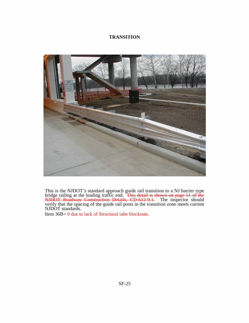
This is the NJDOT’s standard approach guide rail transition to a NJ barrier type bridge railing at the leading traffic end. This detail is shown on page 51 of the NJDOT Roadway Construction Details, CD-612-9.1. The inspector should verify that the spacing of the guide rail posts in the transition zone meets current NJDOT standards. Item 36B= 0 due to lack of Structural tube blockouts.

SF-27
TRANSITION
This shows the transition of the approach guide rail to a NJ Barrier type bridge railing at the leading traffic end. The standard detail for this attachment is shown on page 51 of the NJDOT Roadway Construction Details, CD-612-9.2. The attachment to the bridge railing, rub rail, spacer blocks and pipe spacer meet standards, the post spacing in the transition and single element w-beam do not. Item 36B=0

SF-28
TRANSITION
This shows a steel w-beam transition to the concrete end pylon of a bridge railing. The standard detail for this attachment is shown on page 51 of the NJDOT Roadway Construction Details, CD-612-9.2. The pictured transition does not meet NJDOT standards because it is not properly attached to the end pylon and it lacks adequate post spacing and double rail w-beam in the transition zone. Item 36B=0

74436 Federal Register / Vol. 69, No. 239 / Tuesday, December 14, 2004 / Rules and Regulations
1 The National Highway Institute training may be found at the following URL: http://www.nhi.fhwa.dot.gov./
imposes on the States. These requirements include the development of procedures for follow-up on critical findings.
In the NPRM published on September 9, 2003, the FHWA proposed a burden increase of 67,000 hours for the information collection, OMB control number 2125–0501, and invited interested parties to send comments regarding any aspect of these information collection requirements. Such comments could include, but were not limited to: (1) Whether the collection of information will be necessary for the performance of the functions of the FHWA, including whether the information will have practical utility; (2) the accuracy of the estimated burden; (3) ways to enhance the quality, utility, and clarity of the collection of information; and (4) ways to minimize the collection burden without reducing the quality of the information collected. The FHWA did not receive any comments in response to the proposed burden hour increase of 67,000 hours. The revision to the information collection, OMB control number 2125–0501, based on this final rule will increase the burden hours by only 2,080 hours, a much smaller amount than that originally proposed in the NPRM.
National Environmental Policy Act
The agency has analyzed this action for the purpose of the National Environmental Policy Act of 1969 (42 U.S.C. 4321) and has determined that this action will not have any effect on the quality of the environment.
Executive Order 13211 (Energy Effects)
We have analyzed this rule under Executive Order 13211, Actions Concerning Regulations That Significantly Affect Energy Supply, Distribution, or Use. We have determined that it is not a significant energy action under that order, because although it is a significant regulatory action under Executive Order 12866 it is not likely to have a significant adverse effect on the supply, distribution, or use of energy.
Regulation Identification Number
A regulation identification number (RIN) is assigned to each regulatory action listed in the Unified Agenda of Federal Regulations. The Regulatory Information Service Center publishes the Unified Agenda in April and October of each year. The RIN contained in the heading of this document can be used to cross-reference this action with the Unified Agenda.
List of Subjects in 23 CFR Part 650
Bridges, Grant Programs—transportation, Highways and roads, Incorporation by reference, Reporting and record keeping requirements.
Issued on: December 9, 2004.
Mary E. Peters,
Federal Highway Administrator.
n In consideration of the foregoing, the FHWA is amending title 23, Code of Federal Regulations, part 650, subpart C, as follows:
PART 650—BRIDGES, STRUCTURES, AND HYDRAULICS
n 1. The authority citation for part 650 continues to read as follows:
Authority: 23 U.S.C. 109 (a) and (h), 144, 151, 315, and 319; 33 U.S.C. 401, 491 et seq., 511 et seq.; 23 CFR 1.32; 49 CFR 1.48(b), E.O. 11988 (3 CFR, 1977 Comp. p. 117); Department of Transportation Order 5650.2 dated April 23, 1979 (44 FR 24678); sec. 161 of Public Law 97–424, 96 Stat. 2097, 3135; sec. 4(b) of Public Law 97–134, 95 Stat. 1699; and sec. 1057 of Public Law 102–240, 105 Stat. 2002; and sec. 1311 of Pub. L. 105–178, as added by Pub. L. 105–206, 112 Stat. 842 (1998).
n 2. Revise subpart C to read as follows:
Subpart C—National Bridge Inspection Standards
Sec. 650.301 Purpose. 650.303 Applicability. 650.305 Definitions. 650.307 Bridge inspection organization. 650.309 Qualifications of personnel. 650.311 Inspection frequency. 650.313 Inspection procedures. 650.315 Inventory. 650.317 Reference manuals.
Subpart C—National Bridge Inspection Standards
§ 650.301 Purpose.
This subpart sets the national standards for the proper safety inspection and evaluation of all highway bridges in accordance with 23 U.S.C. 151.
§ 650.303 Applicability.
The National Bridge Inspection Standards (NBIS) in this subpart apply to all structures defined as highway bridges located on all public roads.
§ 650.305 Definitions.
Terms used in this subpart are defined as follows:
American Association of State Highway and Transportation Officials (AASHTO) Manual. ‘‘Manual for Condition Evaluation of Bridges,’’ second edition, published by the American Association of State Highway and Transportation Officials
(incorporated by reference, see § 650.317).
Bridge. A structure including supports erected over a depression or an obstruction, such as water, highway, or railway, and having a track or passageway for carrying traffic or other moving loads, and having an opening measured along the center of the roadway of more than 20 feet between undercopings of abutments or spring lines of arches, or extreme ends of openings for multiple boxes; it may also include multiple pipes, where the clear distance between openings is less than half of the smaller contiguous opening.
Bridge inspection experience. Active participation in bridge inspections in accordance with the NBIS, in either a field inspection, supervisory, or management role. A combination of bridge design, bridge maintenance, bridge construction and bridge inspection experience, with the predominant amount in bridge inspection, is acceptable.
Bridge inspection refresher training. The National Highway Institute ‘‘Bridge Inspection Refresher Training Course’’ 1 or other State, local, or federally developed instruction aimed to improve quality of inspections, introduce new techniques, and maintain the consistency of the inspection program.
Bridge Inspector’s Reference Manual (BIRM). A comprehensive FHWA manual on programs, procedures and techniques for inspecting and evaluating a variety of in-service highway bridges. This manual may be purchased from the U.S. Government Printing Office, Washington, DC 20402 and from National Technical Information Service, Springfield, Virginia 22161, and is available at the following URL: http://www.fhwa.dot.gov/bridge/bripub.htm.
Complex bridge. Movable, suspension, cable stayed, and other bridges with unusual characteristics.
Comprehensive bridge inspection training. Training that covers all aspects of bridge inspection and enables inspectors to relate conditions observed on a bridge to established criteria (see the Bridge Inspector’s Reference Manual for the recommended material to be covered in a comprehensive training course).
Critical finding. A structural or safety related deficiency that requires immediate follow-up inspection or action.
Damage inspection. This is an unscheduled inspection to assess structural damage resulting from environmental factors or human actions.
VerDate jul<14>2003 21:13 Dec 13, 2004 Jkt 205001 PO 00000 Frm 00032 Fmt 4700 Sfmt 4700 E:\FR\FM\14DER1.SGM 14DER1FC-1

74437Federal Register / Vol. 69, No. 239 / Tuesday, December 14, 2004 / Rules and Regulations
Fracture critical member (FCM). A steel member in tension, or with a tension element, whose failure would probably cause a portion of or the entire bridge to collapse.
Fracture critical member inspection. A hands-on inspection of a fracture critical member or member components that may include visual and other nondestructive evaluation.
Hands-on. Inspection within arms length of the component. Inspection uses visual techniques that may be supplemented by nondestructive testing.
Highway. The term ‘‘highway’’ is defined in 23 U.S.C. 101(a)(11).
In-depth inspection. A close-up, inspection of one or more members above or below the water level to identify any deficiencies not readily detectable using routine inspection procedures; hands-on inspection may be necessary at some locations.
Initial inspection. The first inspection of a bridge as it becomes a part of the bridge file to provide all Structure Inventory and Appraisal (SI&A) data and other relevant data and to determine baseline structural conditions.
Legal load. The maximum legal load for each vehicle configuration permitted by law for the State in which the bridge is located.
Load rating. The determination of the live load carrying capacity of a bridge using bridge plans and supplemented by information gathered from a field inspection.
National Institute for Certification in Engineering Technologies (NICET). The NICET provides nationally applicable voluntary certification programs covering several broad engineering technology fields and a number of specialized subfields. For information on the NICET program certification contact: National Institute for Certification in Engineering Technologies, 1420 King Street, Alexandria, VA 22314–2794.
Operating rating. The maximum permissible live load to which the structure may be subjected for the load configuration used in the rating.
Professional engineer (PE). An individual, who has fulfilled education and experience requirements and passed rigorous exams that, under State licensure laws, permits them to offer engineering services directly to the public. Engineering licensure laws vary from State to State, but, in general, to become a PE an individual must be a graduate of an engineering program accredited by the Accreditation Board for Engineering and Technology, pass the Fundamentals of Engineering exam,
gain four years of experience working under a PE, and pass the Principles of Practice of Engineering exam.
Program Manager. The individual in charge of the program, that has been assigned or delegated the duties and responsibilities for bridge inspection, reporting, and inventory. The program manager provides overall leadership and is available to inspection team leaders to provide guidance.
Public road. The term ‘‘public road’’ is defined in 23 U.S.C. 101(a)(27).
Quality assurance (QA). The use of sampling and other measures to assure the adequacy of quality control procedures in order to verify or measure the quality level of the entire bridge inspection and load rating program.
Quality control (QC). Procedures that are intended to maintain the quality of a bridge inspection and load rating at or above a specified level.
Routine inspection. Regularly scheduled inspection consisting of observations and/or measurements needed to determine the physical and functional condition of the bridge, to identify any changes from initial or previously recorded conditions, and to ensure that the structure continues to satisfy present service requirements.
Routine permit load. A live load, which has a gross weight, axle weight or distance between axles not conforming with State statutes for legally configured vehicles, authorized for unlimited trips over an extended period of time to move alongside other heavy vehicles on a regular basis.
Scour. Erosion of streambed or bank material due to flowing water; often considered as being localized around piers and abutments of bridges.
Scour critical bridge. A bridge with a foundation element that has been determined to be unstable for the observed or evaluated scour condition.
Special inspection. An inspection scheduled at the discretion of the bridge owner, used to monitor a particular known or suspected deficiency.
State transportation department. The term ‘‘State transportation department’’ is defined in 23 U.S.C. 101(a)(34).
Team leader. Individual in charge of an inspection team responsible for planning, preparing, and performing field inspection of the bridge.
Underwater diver bridge inspection training. Training that covers all aspects of underwater bridge inspection and enables inspectors to relate the conditions of underwater bridge elements to established criteria (see the Bridge Inspector’s Reference Manual section on underwater inspection for the recommended material to be covered in
an underwater diver bridge inspection training course).
Underwater inspection. Inspection of the underwater portion of a bridge substructure and the surrounding channel, which cannot be inspected visually at low water by wading or probing, generally requiring diving or other appropriate techniques.
§ 650.307 Bridge inspection organization.
(a) Each State transportation department must inspect, or cause to be inspected, all highway bridges located on public roads that are fully or partially located within the State’s boundaries, except for bridges that are owned by Federal agencies.
(b) Federal agencies must inspect, or cause to be inspected, all highway bridges located on public roads that are fully or partially located within the respective agency responsibility or jurisdiction.
(c) Each State transportation department or Federal agency must include a bridge inspection organization that is responsible for the following:
(1) Statewide or Federal agencywide bridge inspection policies and procedures, quality assurance and quality control, and preparation and maintenance of a bridge inventory.
(2) Bridge inspections, reports, load ratings and other requirements of these standards.
(d) Functions identified in paragraphs (c)(1) and (2) of this section may be delegated, but such delegation does not relieve the State transportation department or Federal agency of any of its responsibilities under this subpart.
(e) The State transportation department or Federal agency bridge inspection organization must have a program manager with the qualifications defined in § 650.309(a), who has been delegated responsibility for paragraphs (c)(1) and (2) of this section.
§ 650.309 Qualifications of personnel.
(a) A program manager must, at a minimum:
(1) Be a registered professional engineer, or have ten years bridge inspection experience; and
(2) Successfully complete a Federal Highway Administration (FHWA) approved comprehensive bridge inspection training course.
(b) There are five ways to qualify as a team leader. A team leader must, at a minimum:
(1) Have the qualifications specified in paragraph (a) of this section; or
(2) Have five years bridge inspection experience and have successfully completed an FHWA approved comprehensive bridge inspection training course; or
VerDate jul<14>2003 21:13 Dec 13, 2004 Jkt 205001 PO 00000 Frm 00033 Fmt 4700 Sfmt 4700 E:\FR\FM\14DER1.SGM 14DER1FC-2

74438 Federal Register / Vol. 69, No. 239 / Tuesday, December 14, 2004 / Rules and Regulations
(3) Be certified as a Level III or IV Bridge Safety Inspector under the National Society of Professional Engineer’s program for National Certification in Engineering Technologies (NICET) and have successfully completed an FHWA approved comprehensive bridge inspection training course, or
(4) Have all of the following:(i) A bachelor’s degree in engineering
from a college or university accredited by or determined as substantially equivalent by the Accreditation Board for Engineering and Technology;
(ii) Successfully passed the National Council of Examiners for Engineering and Surveying Fundamentals of Engineering examination;
(iii) Two years of bridge inspection experience; and
(iv) Successfully completed an FHWA approved comprehensive bridge inspection training course, or
(5) Have all of the following: (i) An associate’s degree in
engineering or engineering technology from a college or university accredited by or determined as substantially equivalent by the Accreditation Board for Engineering and Technology;
(ii) Four years of bridge inspection experience; and
(iii) Successfully completed an FHWA approved comprehensive bridge inspection training course.
(c) The individual charged with the overall responsibility for load rating bridges must be a registered professional engineer.
(d) An underwater bridge inspection diver must complete an FHWA approved comprehensive bridge inspection training course or other FHWA approved underwater diver bridge inspection training course.
§ 650.311 Inspection frequency.
(a) Routine inspections. (1) Inspect each bridge at regular intervals not to exceed twenty-four months.
(2) Certain bridges require inspection at less than twenty-four-month intervals. Establish criteria to determine the level and frequency to which these bridges are inspected considering such factors as age, traffic characteristics, and known deficiencies.
(3) Certain bridges may be inspected at greater than twenty-four month intervals, not to exceed forty-eight-months, with written FHWA approval. This may be appropriate when past inspection findings and analysis justifies the increased inspection interval.
(b) Underwater inspections. (1) Inspect underwater structural elements at regular intervals not to exceed sixty months.
(2) Certain underwater structural elements require inspection at less than sixty-month intervals. Establish criteria to determine the level and frequency to which these members are inspected considering such factors as construction material, environment, age, scour characteristics, condition rating from past inspections and known deficiencies.
(3) Certain underwater structural elements may be inspected at greater than sixty-month intervals, not to exceed seventy-two months, with written FHWA approval. This may be appropriate when past inspection findings and analysis justifies the increased inspection interval.
(c) Fracture critical member (FCM) inspections. (1) Inspect FCMs at intervals not to exceed twenty-four months.
(2) Certain FCMs require inspection at less than twenty-four-month intervals. Establish criteria to determine the level and frequency to which these members are inspected considering such factors as age, traffic characteristics, and known deficiencies.
(d) Damage, in-depth, and special inspections. Establish criteria to determine the level and frequency of these inspections.
§ 650.313 Inspection procedures.
(a) Inspect each bridge in accordance with the inspection procedures in the AASHTO Manual (incorporated by reference, see § 650.317).
(b) Provide at least one team leader, who meets the minimum qualifications stated in § 650.309, at the bridge at all times during each initial, routine, in-depth, fracture critical member and underwater inspection.
(c) Rate each bridge as to its safe load-carrying capacity in accordance with the AASHTO Manual (incorporated by reference, see § 650.317). Post or restrict the bridge in accordance with the AASHTO Manual or in accordance with State law, when the maximum unrestricted legal loads or State routine permit loads exceed that allowed under the operating rating or equivalent rating factor.
(d) Prepare bridge files as described in the AASHTO Manual (incorporated by reference, see § 650.317). Maintain reports on the results of bridge inspections together with notations of any action taken to address the findings of such inspections. Maintain relevant maintenance and inspection data to allow assessment of current bridge condition. Record the findings and results of bridge inspections on standard State or Federal agency forms.
(e) Identify bridges with FCMs, bridges requiring underwater inspection, and bridges that are scour critical.
(1) Bridges with fracture critical members. In the inspection records, identify the location of FCMs and describe the FCM inspection frequency and procedures. Inspect FCMs according to these procedures.
(2) Bridges requiring underwater inspections. Identify the location of underwater elements and include a description of the underwater elements, the inspection frequency and the procedures in the inspection records for each bridge requiring underwater inspection. Inspect those elements requiring underwater inspections according to these procedures.
(3) Bridges that are scour critical. Prepare a plan of action to monitor known and potential deficiencies and to address critical findings. Monitor bridges that are scour critical in accordance with the plan.
(f) Complex bridges. Identify specialized inspection procedures, and additional inspector training and experience required to inspect complex bridges. Inspect complex bridges according to those procedures.
(g) Quality control and quality assurance. Assure systematic quality control (QC) and quality assurance (QA) procedures are used to maintain a high degree of accuracy and consistency in the inspection program. Include periodic field review of inspection teams, periodic bridge inspection refresher training for program managers and team leaders, and independent review of inspection reports and computations.
(h) Follow-up on critical findings. Establish a statewide or Federal agency wide procedure to assure that critical findings are addressed in a timely manner. Periodically notify the FHWA of the actions taken to resolve or monitor critical findings.
§ 650.315 Inventory.
(a) Each State or Federal agency must prepare and maintain an inventory of all bridges subject to the NBIS. Certain Structure Inventory and Appraisal (SI&A) data must be collected and retained by the State or Federal agency for collection by the FHWA as requested. A tabulation of this data is contained in the SI&A sheet distributed by the FHWA as part of the ‘‘Recording and Coding Guide for the Structure Inventory and Appraisal of the Nation’s Bridges,’’ (December 1995) together with subsequent interim changes or the most recent version. Report the data using FHWA established procedures as
VerDate jul<14>2003 21:13 Dec 13, 2004 Jkt 205001 PO 00000 Frm 00034 Fmt 4700 Sfmt 4700 E:\FR\FM\14DER1.SGM 14DER1FC-3
74439Federal Register / Vol. 69, No. 239 / Tuesday, December 14, 2004 / Rules and Regulations
1 This Interpretive Guidance focuses on the need to control risks arising out of the relationship between a Money Service Business and its foreign counterparty or agent. Under existing FinCEN regulations, only Money Service Business principals are required to register with FinCEN, and only Money Service Business principals establish the counterparty or agency relationships. 31 CFR 103.41. Accordingly, this Interpretive Guidance only applies to those Money Service Businesses required to register with FinCEN, that is, only those Money Service Businesses that may have a relationship with a foreign agent or counterparty.
outlined in the ‘‘Recording and Coding Guide for the Structure Inventory and Appraisal of the Nation’s Bridges.’’
(b) For routine, in-depth, fracture critical member, underwater, damage and special inspections enter the SI&A data into the State or Federal agency inventory within 90 days of the date of inspection for State or Federal agency bridges and within 180 days of the date of inspection for all other bridges.
(c) For existing bridge modifications that alter previously recorded data and for new bridges, enter the SI&A data into the State or Federal agency inventory within 90 days after the completion of the work for State or Federal agency bridges and within 180 days after the completion of the work for all other bridges.
(d) For changes in load restriction or closure status, enter the SI&A data into the State or Federal agency inventory within 90 days after the change in status of the structure for State or Federal agency bridges and within 180 days after the change in status of the structure for all other bridges.
§ 650.317 Reference manuals.
(a) The materials listed in this subpart are incorporated by reference in the corresponding sections noted. These incorporations by reference were approved by the Director of the Federal Register in accordance with 5 U.S.C. 552(a) and 1 CFR part 51. These materials are incorporated as they exist on the date of the approval, and notice of any change in these documents will be published in the Federal Register. The materials are available for purchase at the address listed below, and are available for inspection at the National Archives and Records Administration (NARA). These materials may also be reviewed at the Department of Transportation Library, 400 Seventh Street, SW., Washington, DC, in Room 2200. For information on the availability of these materials at NARA call (202) 741–6030, or go to the following URL: http://www.archives.gov/federal_register/code_of_federal_regulations/ibr_locations.html. In the event there is a conflict between the standards in this subpart and any of these materials, the standards in this subpart will apply.
(b) The following materials are available for purchase from the American Association of State Highway and Transportation Officials, Suite 249, 444 N. Capitol Street, NW., Washington, DC 20001. The materials may also be ordered via the AASHTO bookstore located at the following URL: http://www.aashto.org/aashto/home.nsf/FrontPage.
(1) The Manual for Condition Evaluation of Bridges, 1994, second edition, as amended by the 1995, 1996, 1998, and 2000 interim revisions, AASHTO, incorporation by reference approved for §§ 650.305 and 650.313.
(2) 2001 Interim Revision to the Manual for Condition Evaluation of Bridges, AASHTO, incorporation by reference approved for §§ 650.305 and 650.313.
(3) 2003 Interim Revision to the Manual for Condition Evaluation of Bridges, AASHTO, incorporation by reference approved for §§ 650.305 and 650.313.
[FR Doc. 04–27355 Filed 12–13–04; 8:45 am]
BILLING CODE 4910–22–P
DEPARTMENT OF THE TREASURY
31 CFR Part 103
Financial Crimes Enforcement Network; Interpretive Release 2004–1—Anti-Money Laundering Program Requirements for Money Services Businesses With Respect to Foreign Agents or Foreign Counterparties
AGENCY: Financial Crimes Enforcement Network (FinCEN), Treasury.
ACTION: Final rule; interpretive release.
SUMMARY: This Interpretive Release sets forth an interpretation of the regulation requiring Money Services Businesses that are required to register with FinCEN to establish and maintain anti-money laundering programs. Specifically, this Interpretive Release clarifies that the anti-money laundering program regulation requires such Money Services Businesses to establish adequate and appropriate policies, procedures and controls commensurate with the risk of money laundering and the financing of terrorism posed by their relationship with foreign agents or foreign counterparties of the Money Services Business.
DATES: Effective June 13, 2005.
FOR FURTHER INFORMATION CONTACT: Office of Regulatory Policy and Programs Division, 1–800–800–2877, Office of Chief Counsel (703) 905–3590 (not a toll free number).
SUPPLEMENTARY INFORMATION: Section 5318(h) of the Bank Secrecy Act, which is codified in subchapter II of chapter 53 of title 31, United States Code, requires every financial institution to establish an anti-money laundering program. The Bank Secrecy Act regulations define financial institution to include money service businesses. On April 29, 2002, FinCEN issued interim final rules-31
CFR 103.125-concerning the application of the anti-money laundering program requirement to money services businesses. 67 FR 21114.
List of Subjects in 31 CFR Part 103
Authority delegations (government agencies), bank, banking, currency, investigations, reporting and recordkeeping requirements.
Department of the Treasury
31 CFR Chapter I
Authority and Issuance
n For the reasons set forth in the preamble, part 103 of title 31 of the Code of Federal Regulations is amended as follows:
PART 103—FINANCIAL RECORDKEEPING AND REPORTING OF CURRENCY AND FOREIGN TRANSACTIONS
n 1. The authority citation for part 103 continues to read as follows:
Authority: 12 U.S.C. 1829b and 1951–1959: 31 U.S.C 5311–5314 and 5316–5332; title III, secs. 312, 313, 314, 319, 326, 352, Pub. L. 107–56, 115 Stat. 307, 12 U.S.C. 1786(q).
n 2. Part 103 is amended by adding a new appendix C to read as follows:
APPENDIX C TO PART 103—INTERPRETIVE RULES
Release No. 2004–01
This Interpretive Guidance sets forth our interpretation of the regulation requiring Money Services Businesses that are required to register with FinCEN to establish and maintain anti-money laundering programs. See 31 CFR 103.125. Specifically, this Interpretive Guidance clarifies that the anti-money laundering program regulation requires Money Services Businesses to establish adequate and appropriate policies, procedures, and controls commensurate with the risks of money laundering and the financing of terrorism posed by their relationship with foreign agents or foreign counterparties of the Money Services Business.1
Under existing Bank Secrecy Act regulations, we have defined Money Services Businesses to include five distinct types of financial services providers and the U.S. Postal Service: (1) Currency dealers or exchangers; (2) check cashers; (3) issuers of traveler’s checks, money orders, or stored
VerDate jul<14>2003 21:13 Dec 13, 2004 Jkt 205001 PO 00000 Frm 00035 Fmt 4700 Sfmt 4700 E:\FR\FM\14DER1.SGM 14DER1FC-4

NEW JERSEY DEPARTMENT OF TRANSPORTATION MEMORANDUM
TO: All Bridge Inspection Staff, Structural Evaluation FROM: James Lane, Manager Structural Evaluation DATE: April 13, 2007 PHONE: 5-3572 SUBJECT: Revision to the 2003 Recording and Coding Guide for the Structure Inventory and Appraisal of New Jersey Bridges ________________________________________________________________________________ The following revision to the subject Manual has been made for the reasons specified below: Page S-20 Item AR – Special Equipment: Revision is necessary to add Maintenance &
Protection of Traffic (code M). Therefore, effective immediately, Item AR (Special Equipment) for Maintenance & Protection of Traffic Code (M) should be coded and also noted at ‘Special Equipment Used’ on the Summary page of the report. This revision will allow us to more easily track the use of and predict the need for MPT to conduct bridge inspections. See revision in Blue on 2003 Recording and Coding Guide page S-20. JL/RCP c: Richard W. Dunne Helene Bowman

ITEM AP - FENDER SYSTEM DIGIT 1 Code the type of Fender system under the structure according to the following codes:
Code Type of Utility Blank None 1 Timber Bents 2 Cofferdam Fenders 3 Steel Piles 4 Steel or Concrete Frames 5 Timber Grids 6 Floating Fenders 7 Butyl Rubber 8 Combination Type Fender 9 Dolphins Only
ITEM AQ - CHAIN LINK FENCE HEIGHT DIGITS 4 Code the height of the chain link fence on the bridge to the nearest hundredth of a foot in the space provided. Leave blank if there is no chain link fence on the bridge. Examples: 4’-6” = 0450 10’-3” = 1025 ITEM AR - SPECIAL EQUIPMENT DIGITS 3 Code one digit (right justification) for each of the following special equipment used:
Equipment Code
Small Boat (less than 16’ long) A Large Boat B Crane C Large Snooper (Reach All, etc.) D Cherry Picker/Bucket Truck E Fathometer F Vertical Lift Truck G Large Ladder (over 24’ long) L Rigging R Snooper (Paxton-Mitchell, etc.) S Timber Testing (moisture, Borings) T UT Thickness Gauge U Barge/Pontoon Boat w/Manlift or Crane P Maintenance & Protection of Traffic (MOT) M
Leave blank if no special equipment is used. If more than three types of special equipment are used, code the most important.
S-20


Introduction Coding of SI&A Item 36—Traffic Safety Features, is probably the most difficult SI&A Item. The reason for this is that the design criteria for the safety features has been revised to require that the various elements be crash tested to assure that they meet the standards established in the NCHRP Report 350 titled “Recommended Procedures for the Safety Performance Evaluation of Highway Features.” Previously, the elements were required to be designed for static loads only. The requirement for crash testing has resulted in many of the previously used details failing to meet the revised standards. Naturally, this has led to the redesign of many of the safety features as new details have passed the crash testing criteria. However, most all of the older safety feature details that were previously constructed are now substandard. In addition, the design of the safety features continue to evolve. This means that today’s standards may quickly become substandard using tomorrow’s new standards and additional crash testing may qualify additional standard details. NCHRP Report 350 titled “Recommended Procedures for the Safety Performance Evaluation of Highway Features” provides uniform guidelines for the crash testing of permanent and temporary highway safety features. Also, the report provides for recommended testing evaluation criteria to assess test results. The Report identifies six “Test Levels”. Each Test Level (TL) is defined by impact conditions (speed and angle of approach) and the type of test vehicle that ranges in size from a small car to a tractor trailer truck. A feature that is designed and tested for a low test level would generally be used on a low service level roadway; such as, a rural collector, local road, or urban street. A feature that is designed for a higher test level would typically be used on a high service roadway such as an Interstate highway. The NJDOT Bridges and Structures Design Manual establishes, in Section 44 of the Manual, what TL designations are to be used on New Jersey highways. The NJDOT standards for the design of safety features are not always suitable for use due to the available space at a particular site. That means that designs for safety features will not all conform to the NJDOT standards. The inspector must understand that the design of a particular safety feature is not necessarily substandard because it was somehow limited by the geometrics at a site. The design at a site would be considered substandard if the design does not conform to the standards and there is also a remedy to eliminate the substandard design. As a first step in understanding how safety features should be evaluated, it is strongly recommended that the inspector first become familiar with the various references that are used to design them, particularly the Standard Construction Details. Once the inspector becomes familiar, it is necessary that changes to the design standards be obtained upon issue and used for subsequent evaluations. Also, Item 36 evaluates the design of the safety features. It does not consider the condition of the safety features. This means that a collision damaged approach guide rail could still be evaluated as meeting standards although it was impacted by an errant vehicle and no longer functions as designed. Furthermore, the field notes in Appendix 4 of the Bridge Survey Report document Item 36 evaluations. While it is acceptable to indicate that the various elements of Item 36, “transitions” for instance, “meets current Department requirements.” It is not acceptable to indicate that an element “does not meet current department requirements.” If an element is substandard, the field notes should include documentation of exactly what portions of the element are substandard.
SF-2

The following document is intended to help the inspector check the adequacy of the design of the more commonly found safety features using the current NJDOT standards. The NJDOT standards must be utilized for evaluating the safety features of all bridges carrying National Highway System (NHS) roadways regardless of ownership. In addition, all NJDOT facilities will also be evaluated using the NJDOT standards regardless of whether or not the bridge carries a NHS highway. For bridges owned by anyone other than NJDOT carrying Non-NHS highways, the owner may set standards below NJDOT and continue to use the static load criteria of the AASHTO Standard Specifications for Highway Bridges. The inspector should also understand the difference between the NJDOT standards for evaluating safety features and the standards used for new designs. For example, Detail CD-609-10.1 of the Standard Roadway Construction Details shows a reinforced concrete balustrade with supplemental steel w-beam attached. While this details meets NJDOT standards, it most definitely would not be used for new designs. Obviously, it is not possible to list all of the different type safety feature installations that exist. For more obscure types, such as bridge railings on through girders or through trusses or timber bridges, the inspector should use the standards as a guide to the extent possible in making the assessment.
SF-3

Bridge Railings The design/evaluation of bridge railings is performed in accordance with the following references:
1. AASHTO LRFD Bridge Design Specifications for Highway Bridges—Section 13 2. NJDOT Bridges and Structures Design Manual—Section 1.23.2-Types of Parapets,
Bridge Railings and Section 1.44-Alternative Design Criteria Non-NHS Highways. 3. NJDOT Standard Roadway Construction – Traffic Control – Bridge Construction Details
2007 - Sheets 58 thru 75 4. NJDOT Bridges and Structures Design Manual—Section 2.2-1 5. NCHRP Report 350, “Recommended Procedures for the Safety Performance Evaluation
of Highway Features” 6. AASHTO Roadside Design Guide, 2002
Railings on bridges carrying only interstate highways (not Freeway) must meet the TL-5 (Test Level 5) crash testing standard. At present, NJDOT has specified the use of the 3'-6" (1067mm) “F” and “Texas HT” type railings to meet this requirement. As such, nearly all railing systems on interstate highway bridges would be substandard at this time. All other State-owned or NHS highway bridge railings must meet the TL-4 crash testing standard. The railing systems shown in Section 1.23.2 of the Bridges and Structures Design Manual meet the TL-4 standards. For bridges that are non-State-owned, non-NHS classified roadways, the use of Test Level systems lower than TL-4 is permitted. The railing system for non-State-owned, non-NHS bridges is designed based on an evaluation of the roadway classification, design speed and truck traffic data. When evaluating the adequacy of bridge railings, the inspector should check the following areas (only the 3'-6" “F” (NJ shape), 3'-6"vertical rectangular shape and “Texas HT” railings currently meet TL-5 standards for bridges carrying interstate highways only):
1. Reinforced Concrete Parapet Bridge Railings: A. Check the height of the railing—it must be 2'-8" or higher. Most of the older
parapets of this design were only 2'-3"or 2'-6" high. B. This type railing system is often surmounted with an ornamental steel or
aluminum rail. The height of this ornamental rail is not to be considered when evaluating the height of the bridge railing.
C. If the reinforced concrete parapet has been supplemented by the installation of a galvanized steel w-beam railing system mounted independently to the sidewalk/safetywalk, the steel w-beam is the bridge railing and the height of the reinforced concrete parapet is not relevant.
2. Reinforced Concrete Balustrade Bridge Railings: A. These type bridge railing systems fail due to structural and geometric standards
and are always substandard unless reinforced with steel w-beam. B. A reinforced concrete balustrade reinforced by the addition of a galvanized steel
w-beam guide rail in accordance with the Standard Roadway Construction Details Sheet 67 is considered to be acceptable.
SF-4
3. Galvanized Steel W-Beam Guide Rail Bridge Railings:
A. These systems are to be evaluated using the standards shown in the Standard Roadway Construction Details Sheet 67.
B. To meet standards, the system should conform to the following: Double Rail Thickness; Post Spacing—3'-1½"; Recycled Synthetic Spacer Blocks; 2'-3¼" Height; W-Beam Mounted Flush with Curbline; Rub-Rail.
NOTE: The Reinforced Concrete Balustrade Bridge Railing supplemented with a galvanized steel w-beam guide rail along with the Galvanized Steel W-Beam Guide Rail Bridge Railing Systems, although included in the NJ Standards, have not been tested using NCHRP 350 Test Level (TL) criteria. Two w-beam systems that were tested only met TL-2 criteria. Several thrie-beam guide rails meeting TL-3 and TL-4 criteria have been approved by the Department.
SF-5

Transitions
The design/evaluation of transitions (guide rails and curbs) is performed in accordance with the following references:
1. AASHTO Roadside Design Guide, 2002 2. NJDOT Design Manual—Roadway—Section 8-Guidelines for Guide Rail Design and
Median Barriers 3. NJDOT Standard Roadway Construction – Traffic Control – Bridge Construction Details
2007 - Sheets 58 thru 75 Throughout this section, the following terminology is used:
1. “Leading” traffic end transitions—This is the end of the bridge railing that is exposed to oncoming traffic or located at the exit end of a bridge railing on a two way roadway that is within the “clear zone” for traffic barrier warrants.
2. “Trailing” traffic end transitions—This is the end of the bridge railing that is not exposed to oncoming traffic or is not located within the “clear zone” for traffic barrier warrants on a two way roadway. This also applies to situations where the transition area is within the “clear zone”, but is otherwise shielded from impacts by other traffic barriers.
When evaluating the adequacy of transitions (guide rails and curbs), the inspector should check the following areas:
1. Transitions to Reinforced Concrete Bridge Railing and NJ Barrier Parapets:
A. To meet standards, the system should conform to the following at the leading traffic end: NJ shape barrier transitions to vertical shape; 1st Post at 11½" after end of concrete pylon or end of parapet; Followed by 5 Posts spaced at 1'-6¾", and then 3 Posts spaced at 3'-1½" in transition. Two sections of thrie beam one set inside the other (see Sheets 70 through 73) 1'-8" deep thrie-beam guide rail 2'-8" high attached to parapet; one 7'-3½” long transition section from thrie to w-beam guide rail (see Sheet 69); Structural tube blockouts at thrie beam section; Recycled Synthetic spacer blocks at w-beam section; Thrie beam bolted to face of parapet (See Sheets 70, 71 and 72).
B. To meet standards, the system should conform to the following at the trailing traffic end (if required): NJ shape barrier transitions to vertical shape; First post spaced 30¼" from parapet end; Steel w-beam bolted to face of parapet in 3½" deep cutout; Recycled Synthetic spacer blocks; Rub rail (if curb is present) ( See Sheets 70, 71 and 72).
SF-6

2. Transitions to Reinforced Concrete Balustrades: A. These systems are to be evaluated using the standards shown in the Standard
Roadway Construction Details Sheet 67. B. To meet standards, the system should conform to the following at the leading
traffic end: First post at 3'-1½" max. from the centerline of pipe spacer; Post spacing - 4 @ 1'-6¾" immediately adjacent to the balustrade; Post spacing - 4 @ 3'-1½" in transition; Recycled Synthetic spacer blocks; Steel pipe spacer at pilaster; 2'-3¼" high steel w-beam guide rail; Double thickness steel w-beam in transition; Rub rail (if curb is present).
C. To meet standards, the system should conform to the following at the trailing traffic end (if required): First post spaced 3'-1½" from pilaster end; Recycled Synthetic spacer blocks; Rub rail (if curb is present).
3. Transitions to Bridge Mounted Steel W-Beam Bridge Railing: A. These systems are to be evaluated using the standards shown in the Standard
Roadway Construction Details Sheet 67. B. To meet standards, the system should conform to the following at the leading
traffic end: First post at 3'-1½" max. from the centerline of post at bridge; Post spacing - 4 @ 1'-6¾" immediately adjacent to the bridge railing; Post spacing - 4 @ 3'-1½" in transition; Recycled Synthetic spacer blocks; Double thickness steel w-beam in transition—12'-6" length; Rub rail (if curb is present).
C. To meet standards, the system should conform to the following at the trailing traffic end (if required): First post spaced 3'-1½" from end of bridge railing; Recycled Synthetic spacer blocks; Rub rail (if curb is present).
4. Curb Transitions should be tapered or flared if exposed to oncoming traffic at all
installations.
SF-7
Approach Guardrail (Guide Rail) The design/evaluation of guide rails is performed in accordance with the following references:
1. AASHTO Roadside Design Guide, 2002 2. NJDOT Design Manual—Roadway—Section 8-Guidelines for Guide Rail Design and
Median Barriers 3. NJDOT Standard Roadway Construction – Traffic Control – Bridge Construction Details
2007 - Sheets 58, 59 and 60 Throughout this section, the following terminology is used:
1. “Leading” traffic end - This end of the guide rail system is exposed to oncoming traffic or located at the exit end of a guide rail system on a two way roadway that is within the “clear zone” for traffic barrier warrants.
2. “Trailing” traffic end - This end of the guide rail system is not exposed to oncoming traffic or is not located within the “clear zone” for traffic barrier warrants on a two way roadway. This also applies to situations where the guide rail system is within the “clear zone”, but is otherwise shielded from impacts by other traffic barriers.
The need for guide rail placement is determined based on the location of “warrants” within the “clear zone” of the roadway. For purposes of this document, we are primarily concerned about bridge railings and bridge railings are always “warrants” since the “leading” end is almost always located within the “clear zone”. The “trailing” end may or may not be located within the “clear zone” for traffic coming in the opposite direction for two way traffic roadways. As previously discussed, safety systems are designed. Part of the design is the determination of the length of need for the guide rail. The length of need is primarily based on the distance from the edge of traveled way to the warranting obstruction, the “depth” of the obstruction (or warrant) from the edge of traveled way (important when considering retaining walls between structures and cross slopes outside structures), design speed of the roadway and average daily traffic. The calculation for this length is complex due to the need for information not readily available to the inspector. Therefore, this calculation is not performed within the scope-of-work of a routine bridge inspection project. In addition, it is usually common for there to be multiple warranting objects located at bridges, primarily cross slopes. Cross slopes on roadway embankments (or cuts) are warranting objects when they exceed specified heights for various cross slopes. This fact means that only the length of need for the end of the bridge railing could be calculated (assuming the design speed of the roadway is known) and this would not always provide the actually required length of need.
SF-8
Example Clear Zone Distances: Assumptions:
1. Fill Slope 1:6 or flatter (Slope 1:5 to1:4) 2. ADT over 6000 3. Clear Zone—Based on design speed and ADT (see Figure 8-A in Design Manual—
Roadway)
Clear Zone Distance (Max.)
Design Speed 70mph 60mph 55mph 50mph 40mph or less
Clear Zone Dist. -Fill Slope 1:6 or flatter 34’ 32’ 24’ 20’ 16’
Clear Zone Dist. – Slope 1:5 to 1:4 46’ 44’ 32’ 28’ 18’
Example Lengths of Need:
1. Guide rail warrant is bridge parapet and slope (or retaining wall) - Warrant extends transversely to end of Clear Zone
2. Fill Slope 1:6 or flatter 3. Shoulder width—10'; No Sidewalk 4. Clear Zone—Based on design speed and ADT (see Figure 8-A in Design Manual -
Roadway) 5. Roadway is on tangent alignment - no horizontal curve 6. Parabolic flare SRT end treatment 7. Calculations based on Figure 8-E in Design Manual - Roadway
Roadway Design Speed (see Notes below)
Design Speed 70mph 60mph 50mph 40mph 25mph Length of Need (ADT > 6000) 480 ft. 400 ft. 320 ft. 240 ft. 120 ft. Length of Need (ADT 2000-6000) 440 ft. 360 ft. 290 ft. 220 ft. 110 ft. Length of Need (ADT 800-2000) 400 ft. 330 ft. 260 ft. 200 ft. 100 ft. Length of Need (ADT < 800) 360 ft. 300 ft. 240 ft. 180 ft. 90 ft. Notes:
1. The calculated Length of Need would be rounded up to the next multiple of 12.5' that represents the length of one guide rail element.
2. An additional length of 12.5' would be added to the above Length of Need to represent the end section of the Slotted Rail Terminal (SRT) or Extruder Terminal (ET) that is not considered in the calculation.
3. The minimum Length of Need for an SRT is 56 ft. and 69 ft. for an ET. When evaluating the adequacy of guide rails at bridges, the inspector should check the following: Galvanized steel w-beam guide rail height - 2'-3¼"; Posts spaced @ 6'-3"; Recycled Synthetic spacer blocks; Adequate length provided (based on judgment). NOTE: When needed, guide rails at the trailing traffic end of bridges require less length than those at the leading traffic end.
SF-9

Miscellaneous:
1. When the length of the guide rail installation is clearly longer than is necessary for the warrant caused by the bridge alone, the inspector should indicate that it is adequate by stating it is “continuous” in the bridge survey report field notes.
2. When the approach guide rail is carried across a culvert (or other sub-grade structure),
this meets the current standards for bridge railing, transitions and approach guide rail. If the end treatments meet standards or guide rails are continuous, the Item 36 code would be “1111.”
SF-10

Approach Guardrail (Guide Rail) Ends The design/evaluation of ends (guide rails and parapets) is performed in accordance with the following references:
1. AASHTO Roadside Design Guide, 2002 2. NJDOT Design Manual – Roadway - Section 8 - Guidelines for Guide Rail Design and
Median Barriers 3. NJDOT Design Manual – Roadway - Section 9 - Guidelines for the Selection and Design
of Crash Cushions 4. NJDOT Standard Roadway Construction – Traffic Control – Bridge Construction Details
2007 - Sheets 61, 62, 63 and 64 Throughout this section, the following terminology is used:
1. “Leading” traffic end - This end of the guide rail system is exposed to oncoming traffic or located at the exit end of a guide rail system on a two way roadway that is within the “clear zone” for traffic barrier warrants.
2. “Trailing” traffic end - This end of the guide rail system is not exposed to oncoming traffic or is not located within the “clear zone” for traffic barrier warrants on a two way roadway. This also applies to situations where the end of the guide rail system is within the “clear zone”, but is otherwise shielded from impacts by other traffic barriers.
The standards for “leading” traffic end terminations within the “clear zone” are:
A. Flared Guide Rail Terminal like Slotted Rail Terminals (SRT350) or Flared Energy-Absorbing Terminal (FLEAT): Standard end terminal where room exists for a parabolic flare. For details see the Manufacturer’s recommendation and the Department Qualified Products list.
B. Tangent Guide Rail Terminal like Extruder Terminals (ET-2000) or Sequential Kinking Terminal (SKT-350): End terminal used where insufficient room exists for parabolic flare. For details see the Manufacturer’s recommendation and the Department Qualified Products list.
C. Controlled Release Terminals (CRT): End terminal used where insufficient space exists at driveways or intersecting streets. For details, see Sheet 63 of Roadway Construction Details.
D. Crash Cushions (Impact Attenuators): Used where space limits preclude the use of the two standard end terminals specified above.
E. Telescoping Guide Rail End Terminals: Used where there are back-to-back guide rails (usually within the median). Typically, this is used in conjunction with sign structures where the support is located in the median. For details, see Sheet 64 of the Roadway Construction Details.
The standard for “trailing” traffic end terminations or where it is unlikely that an end hit would occur (i.e., end of guide rail is outside “clear zone”, end of guide rail buried in cut, etc.):
A. Beam Guide Rail Anchorage: Standard beam anchorage terminal. For details, see Sheet 61 of Roadway Construction Details.
B. In-Line Beam Guide Rail Anchorage: Anchorage used where end of guide rail is buried in a cut slope. For details, see Sheet 61 of Roadway Construction Details.
Many of the older safety systems used Breakaway Cable Terminals (BCT) or Eccentric Loader Terminals (ELT). These two end terminals did not pass the mandatory crash testing and no longer meet NJDOT standards.
SF-11

BRIDGE RAILING, TRANSITION, GUIDE RAIL AND END TERMINAL
SF-12
This shows the NJDOT’s standard NJ Barrier type bridge railing. This detail is shown as Type 5 in the NJDOT Bridges and Structures Design Manual, Section 1.23.2. The NJ Barrier type bridge railing is acceptable for use in all installations. However, the railing height for Interstate highways must be 3'-6" rather than the standard height of 2'-10". The lack of an approach guide rail system at the trailing traffic end of the bridge railing is noted. The end of the bridge railing is not exposed to traffic and the flat slope of the grass median means there are no guide rail warrants. Therefore, the lack of guide rail is the appropriate design for this location. Item 36A=1; Item 36B=1; Item 36C=1; Item 36D=1; Item AG=8; Pontis Element=331 (Reinforced Concrete)

SF-13
BRIDGE RAILING
This shows a rectangular concrete bridge railing retrofitted with a steel w-beam guide rail mounted directly to the original bridge railing. This detail is not shown in the NJDOT Roadway Construction Details. However, the combination system would meet NJDOT standards provided that the guide rail height, spacer block spacing and double-element w-beam meet standards. This type bridge railing is acceptable for use in all installations provided the retrofitted guide rail meets standards. Item 36A=1; Item AG=48; Pontis Element=333 (Combination)

SF-14
BRIDGE RAILING
This shows a reinforced concrete balustrade retrofitted with a steel w-beam guide rail mounted directly to the original bridge railing. This detail is shown on Sheet 67 of the NJDOT Roadway Construction Details, CD-609-10.1. This type of combination bridge railing system would meet NJDOT standards provided that the guide rail height, spacer block spacing, backing plates and double-element w-beam meet standards. This type installation is commonly found on older structures. This particular installation lacked double-element w-beam and backing plates. Item 36A=0; Item AG=47; Pontis Element=333 (Combination)

SF-15
BRIDGE RAILING
This shows a reinforced concrete balustrade bridge railing where a bridge mounted steel w-beam bridge rail has been installed along the curbline as a replacement. The bridge railing in this situation is the steel w-beam. This detail is shown on Sheet 67 of the NJDOT Roadway Construction Details, CD-609-10.2. The inspector should check to verify that double element w-beam is used along with proper post spacing, routed timber or plastic spacer blocks and rub rail (when necessary) are used. In this particular installation, the system is substandard due to the presence of a single element w-beam. Item 36A=0; Item AG=27; Pontis Element=334 (Metal-Coated)
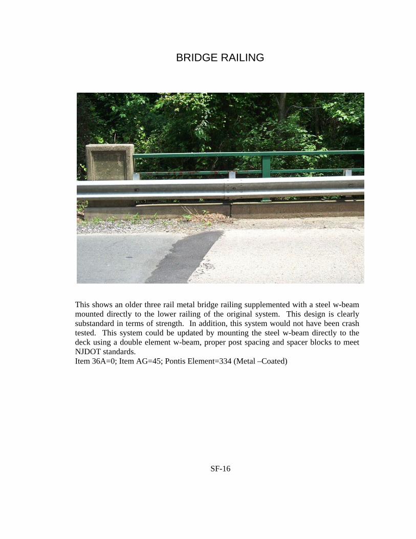
SF-16
BRIDGE RAILING
This shows an older three rail metal bridge railing supplemented with a steel w-beam mounted directly to the lower railing of the original system. This design is clearly substandard in terms of strength. In addition, this system would not have been crash tested. This system could be updated by mounting the steel w-beam directly to the deck using a double element w-beam, proper post spacing and spacer blocks to meet NJDOT standards. Item 36A=0; Item AG=45; Pontis Element=334 (Metal –Coated)

SF-17
BRIDGE RAILING AND TRANSITION
This shows the transition at an older substandard three rail metal bridge railing system. This particular installation is substandard because the post spacing in the transition zone is greater than allowed. This is the result of the location of the storm inlet that prevents the normal installation of posts. Posts could be installed provided additional spacer blocks are used to bridge over the storm inlet. The three rail metal bridge railing does not meet current NJDOT standards and is substandard on all NJDOT infrastructure. Item 36A=0; Item 36B=0; Item AG=05; Pontis Element=333 (Combination)

SF-18
BRIDGE RAILING AND TRANSITION
This shows a non-standard design rectangular reinforced concrete bridge railing. The design strength and geometry of the bridge railing would appear adequate based on inspection. However, the presence of the brush curb would most likely cause the bridge railing to fail crash testing (Note that none of the standard bridge railings shown in Section 23 of the NJDOT Design Manual for Bridges and Structures have brush curbs). The transition appears to meet current NJDOT standards excepting the spacing to the first post that appears greater than the 1'-6¾" standard. This may have been caused by the proximity of the wingwall that may have precluded placing the post at the correct location. Item 36A=0; Item 36B=0; Item AG=8; Pontis Element=331 (Reinforced Concrete)

SF-19
BRIDGE RAILING AND TRANSITION
This shows a rectangular reinforced concrete bridge railing with single ornamental metal rail. This detail is shown as Type 4 in Section 23 of the NJDOT Design Manual for Bridges and Structures. As such, it meets current NJDOT standards for low level, short span bridges over shallow streams or drainage areas. The height of the concrete portion of the railing must be 2'-8" high. This should be checked by the inspector as older designs were 2'-3" or 2'-6" high. The trailing traffic end of the bridge railing is exposed to traffic impacts from traffic traveling in the opposite direction. If the bridge railing is within the clear zone, it is a warrant for guide rail. If it is outside the clear zone, nothing is required. Since the distance from the roadway centerline to this location is 18', it is outside the clear zone and guide rail is not required. Item 36A=1; Item 36B=1; Item AG=2; Pontis Element=333 (Combination)

SF-20
BRIDGE RAILING AND TRANSITION
Typical detail for a D&R Canal bridge with retrofitted bridge railing and guide rail transition. The bridge railing is a unique design for D&R Canal bridges and has not been crash tested. However, due to the low traffic volume and speeds on the D&R Canal bridges, this bridge railing is deemed to meet current NJDOT standards. The guide rail attachment detail is likewise unique, but is also deemed to meet NJDOT standards. The inspector should check that the transition has double element guide rail and post spacing that meets the current standards. Item 36A=1; Item 36B=1; Item AG=18; Pontis Element=334 (Metal—Coated)

SF-21
BRIDGE RAILING AND TRANSITION
This shows a concrete encased through girder type bridge railing retrofitted with a steel w-beam guide rail mounted on top. This detail is somewhat unusual and is not shown in the NJDOT Roadway Construction Details. Obviously, this detail was not crash tested. However, it would appear to meet design criteria based on inspection (excepting the lack of a double rail w-beam). The transition zone is clearly substandard due to the lack of adequate post spacing and lack of double rail w-beam. Item 36A=0; Item 36B=0; Item AG=18; Pontis Element=333 (Combination)

SF-22
BRIDGE RAILING AND TRANSITION
This shows a double rail w-beam bridge railing with the approach guide rail carried into the transition zones at both approaches. This detail is somewhat unique and is not shown in the NJDOT Roadway Construction Details. The bridge railing lacks spacer blocks on the posts. In addition, the posts appear to be mounted on the outside bridge fascia bringing the strength of the system into question. This type of system would not have been crash tested. The guide rail in the transition zone lacks adequate post spacing, spacer blocks and double rail w-beam. Finally, the ends of the curb are not tapered and are exposed to impacts. Item 36A=0; Item 36B=0; Item AG=18; Pontis Element=334 (Metal-Coated)

This is the NJDOT’s standard thrie beam guide rail transition to a concrete bridge railing at the leading traffic end. This detail is shown on Sheet 70 of the NJDOT Roadway Construction Details, CD-609-13. The inspector should verify that the spacing of the guide rail posts in the transition zone meets current NJDOT standards. Item 36B = 1 due to Structural tube blockouts.
SF-23
GUIDE RAIL TRANSITION

SF-24
BRIDGE RAILING, TRANSITION, GUIDE RAIL AND END TERMINAL
This shows a rectangular reinforced concrete bridge railing with a single ornamental metal rail. This detail is shown as Type 4 in Section 23 of the NJDOT Design Manual for Bridges and Structures. As such, it meets NJDOT standards for low level, short span bridges over shallow streams or drainage areas. The inspector should check the height of the bridge railing to verify that it is 2'-8". The leading traffic end of the bridge railing is exposed to vehicle impacts. The inspector should check to verify if this location is within the clear zone. If so, the design would be substandard. In this particular case, the end of the bridge railing is 18' from the edge of the traffic lane which is outside the clear zone. Item 36A=1; Item 36B=1; Item 36C=1; Item 36D=1; Item AG=02; Pontis Element=333 (Combination)

SF-25
BRIDGE RAILING, TRANSITION, GUIDE RAIL AND END TERMINAL
This shows an older two pipe metal bridge railing with steel w-beam approach guide rail. Just about everything is substandard. The bridge railing would fail both in strength and geometry. The approach guide rail transition lacks adequate post spacing, spacer blocks, double rail w-beam and attachment to the bridge railing. The approach guide rail lacks spacer blocks, adequate post spacing and adequate length. Finally, there is no end terminal. Item 36A=0; Item 36B=0; Item 36C=0; Item 36D=0, Item AG=18; Pontis Element=334 (Metal-Coated)

SF-26
TRANSITION
This is the NJDOT’s standard approach guide rail transition to a NJ barrier type bridge railing at the leading traffic end. The inspector should verify that the spacing of the guide rail posts in the transition zone meets current NJDOT standards. Item 36B= 0 due to lack of Structural tube blockouts.

SF-27
TRANSITION
This shows the transition of the approach guide rail to a bridge railing retrofitted with a supplemental w-beam guide rail at the leading traffic end. This detail is not shown in the NJDOT Roadway Construction Details. The inspector should check that the guide rail is a double element and that the post spacing meets standards in the transition zone. Also, due to the presence of a curb, a rub rail must be present to meet standards. This type transition is acceptable for use at all leading traffic end installations. Item 36B=1

SF-28
TRANSITION
This shows the transition of the approach guide rail to a NJ Barrier type bridge railing at the leading traffic end. The attachment to the bridge railing, rub rail, spacer blocks and pipe spacer meet standards, the post spacing in the transition and single element w-beam do not. Item 36B=0

SF-29
TRANSITION
This shows a steel w-beam transition to the concrete end pylon of a bridge railing. The pictured transition does not meet NJDOT standards because it is not properly attached to the end pylon and it lacks adequate post spacing and double rail w-beam in the transition zone. Item 36B=0

SF-30
TRANSITION
This shows a substandard transition to a reinforced concrete balustrade type bridge railing where the guide rail has been installed as a supplement to the original bridge railing. This installation is substandard because there is no double-element w-beam in the transition zone. Also, the post spacing in the transition zone is substandard. Finally, the pipe spacer at the end pylon of the balustrade is lacking. The standard detail for this installation is shown on Sheet 67 of the NJDOT Roadway Construction Details, CD-609-10.1. Item 36B=0

SF-31
TRANSITION
This shows the guide rail transition zones at the end of a bridge carrying two way traffic without a median barrier. The transition at the right is a typical design for the leading traffic end of a bridge railing. The transition on the left is a different matter since the inspector must determine whether the guide rail “warrant” (end of bridge railing) is within the “clear zone” for traffic traveling in the right hand lane. Since the curb-to-curb width is 30' and the sidewalk width is 6', the end of the bridge railing is 21' from the centerline of the roadway. This means that the end of the bridge railing is outside the “clear zone” for speeds of up to 50mph. If the speed limit on this road is less than or equal to 50mph, the end of the bridge railing requires a transition for the trailing traffic end condition rather than the leading traffic end condition. For posted speeds of over 50mph, the end of the bridge railing is a “warrant” within the “clear zone” and requires a transition for the leading traffic end condition similar to what is on the right.

SF-32
TRANSITION, GUIDE RAIL AND END TERMINAL
This shows the trailing traffic end of a bridge railing in the median of an interstate highway. The end of the bridge railing is not exposed to impacts by traffic carried by the bridge. It is also outside the “clear zone” for traffic carried by the twin bridge. Therefore, there is no “warrant” for guide rail at this location. Item 36B=1; Item 36C=1; Item 36D=1

SF-33
END TERMINAL
This is the NJDOT’s standard Slotted Rail Terminal (SRT-350). This end terminal is acceptable and meets current NJDOT standards for all installations. It is typically used where room to flare the guide rail exists. Where inadequate space exists to flare, the Extruder Terminal (ET-2000) would be used for most installations. Item 36D=1
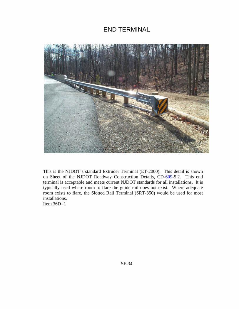
SF-34
END TERMINAL
This is the NJDOT’s standard Extruder Terminal (ET-2000). This detail is shown on Sheet of the NJDOT Roadway Construction Details, CD-609-5.2. This end terminal is acceptable and meets current NJDOT standards for all installations. It is typically used where room to flare the guide rail does not exist. Where adequate room exists to flare, the Slotted Rail Terminal (SRT-350) would be used for most installations. Item 36D=1
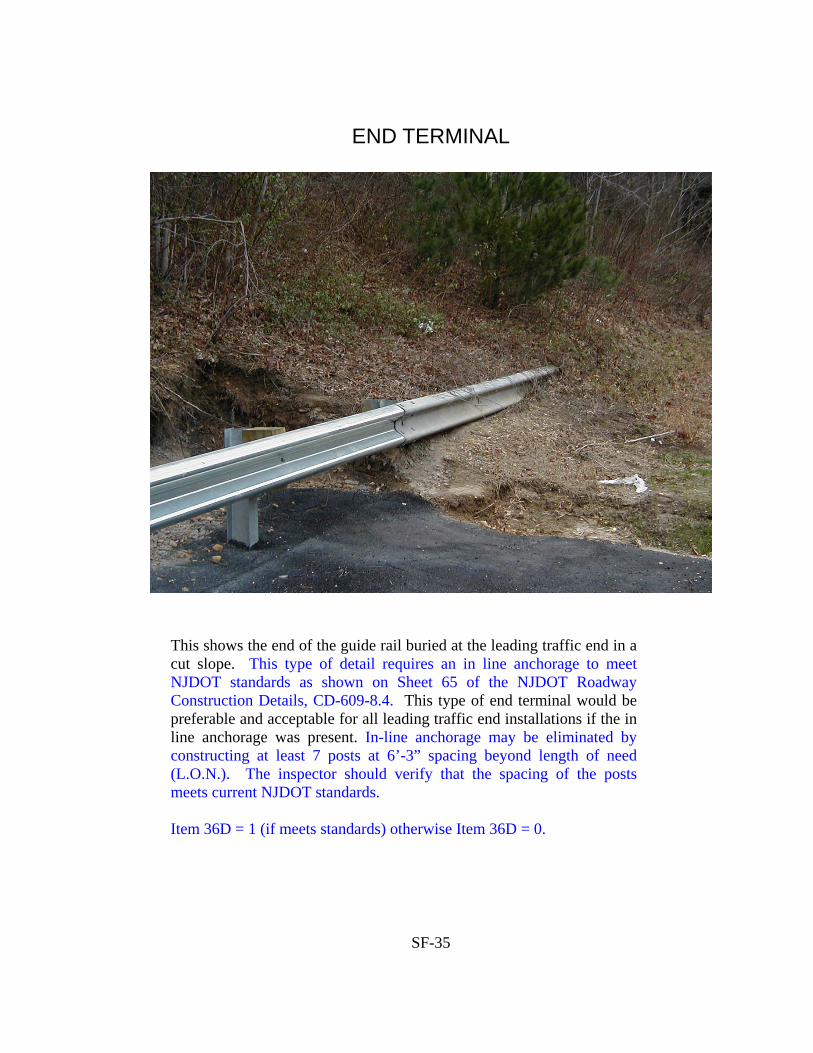
SF-35
END TERMINAL
This shows the end of the guide rail buried at the leading traffic end in a cut slope. This type of detail requires an in line anchorage to meet NJDOT standards as shown on Sheet 65 of the NJDOT Roadway Construction Details, CD-609-8.4. This type of end terminal would be preferable and acceptable for all leading traffic end installations if the in line anchorage was present. In-line anchorage may be eliminated by constructing at least 7 posts at 6’-3” spacing beyond length of need (L.O.N.). The inspector should verify that the spacing of the posts meets current NJDOT standards. Item 36D = 1 (if meets standards) otherwise Item 36D = 0.

SF-36
END TERMINAL
This shows the end of a Controlled Release Terminal (CRT). The CRT is the entire curved treatment rather than just the end as shown in the photo. This detail is shown on Sheet 63 of the NJDOT Roadway Construction Details, CD-609-6.2. This type end terminal is rarely found on bridge installations. However, it is occasionally found where low volume roads intersect arterial highways and there is a need to terminate the guide rail to provide pedestrian access. This end terminal is acceptable and meets current NJDOT standards for leading traffic end installations on low volume roads or driveways. Item 36D=1
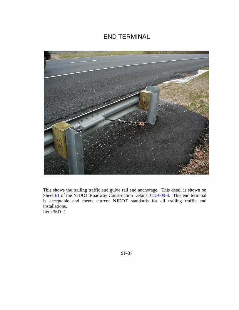
SF-37
END TERMINAL
This shows the trailing traffic end guide rail end anchorage. This detail is shown on Sheet 61 of the NJDOT Roadway Construction Details, CD-609-4. This end terminal is acceptable and meets current NJDOT standards for all trailing traffic end installations. Item 36D=1

SF-38
END TERMINAL
This shows a Breakaway Cable Terminal (BCT) with collision damage at the leading traffic end. The BCT saw widespread use throughout New Jersey. However, it failed crash testing, no longer meets NJDOT standards and is not shown in the NJDOT Roadway Construction Details. It is always evaluated as substandard on NJDOT infrastructure. It may be acceptable for bridge owners in New Jersey for highways not on the NHS. Item 36D=0 NOTE: The presence of the collision damage would not affect the evaluation of the safety features. In fact, the end terminal could be completely destroyed by impact damage and the design could still meet standards.

SF-39
END TERMINAL
This shows an Eccentric Loader Terminal (ELT). This type end terminal no longer meets NJDOT standards. It is always evaluated as substandard on NJDOT infrastructure. Item 36D=0
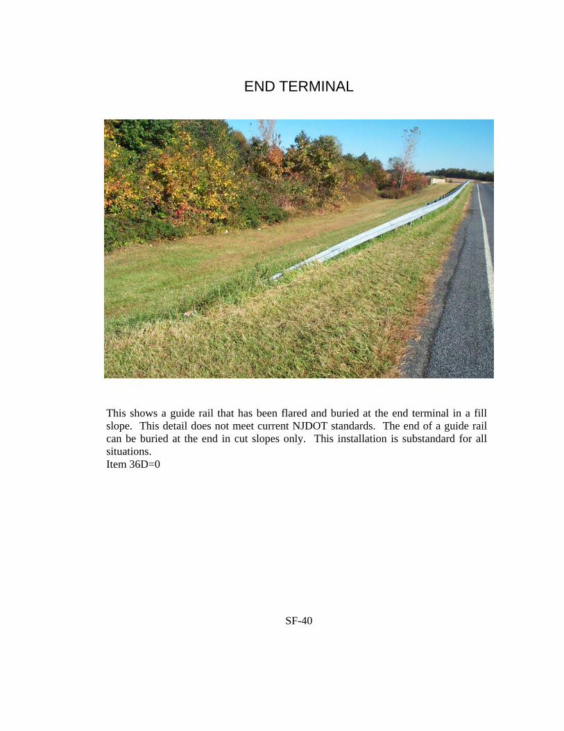
SF-40
END TERMINAL
This shows a guide rail that has been flared and buried at the end terminal in a fill slope. This detail does not meet current NJDOT standards. The end of a guide rail can be buried at the end in cut slopes only. This installation is substandard for all situations. Item 36D=0

SF-41
END TERMINAL
This shows a typical telescoping guide rail end terminal of the telescoping type. This detail is shown on Sheet 64 of the NJDOT Roadway Construction Details, CD-609-7.3. This type end terminal is rarely used on bridges. However, it is commonly used on highway underpass structures when a pier is located in the median. However, the adequacy of such installations is not evaluated when determining the coding for Item 36.

SF-42
END TERMINAL
This shows a Median Breakaway Cable Terminal (MBCT). The replacement for this type end terminal is either the CAT or BREAKMASTER. This type end terminal is rarely used on bridges. However, it is commonly used on highway underpass structures when a pier is located in the median as shown above. However, the adequacy of such installations is not evaluated when determining the coding for Item 36.

ITEM DJ - MINIMUM VERTICAL UNDERCLEARANCE DIGITS 4
INCLUDING SHOULDERS (XX.XX feet)
Record and code a four-digit number to represent in feet, minimum vertical clearance from the
roadway (including shoulders) beneath the structure to the underside of the superstructure. Code
zeros for structures over any other feature.
In addition to coding this Item on sheet 1, it should also be coded on sheets 2 and A thru Z.
Sheet 2 would be coded the same as sheet 1, but sheets A thru Z would be coded for the
individual features intersected.
When sheets A thru Z are coded, sheet 1 should always be coded for the absolute minimum of all
features beneath the structure.
ITEM FA - FHWA SCOUR REPORTING CATEGORIES DIGITS 2
Code the current FHWA Reporting Category for the bridge based upon the information and
results obtained during the Bridge Scour Evaluation program:
LOW RISK BRIDGE - STAGE 2 NOT REQUIRED and STAGE 2 DONE
Code Reporting Category Comments
01 Assessed (old bridge) Pre HEC-18 Design - Stage 1 not performed
11 Assessed (new/old
bridge with Scour
Countermeasures )
Foundations designed in accordance with HEC-18
or Scour Countermeasures designed in accordance
with HEC-23
02 Screened Stage 1 performed
03 Culvert
SCOUR SUSCEPTIBLE BRIDGE - STAGE 2 REQUIRED
Code Reporting Category Comments
04 Screened Known foundation details and non-tidal waterway
05 Unknown Foundations
06 Tidal Waterway Foundation details known
OTHER CATEGORIES
Code Reporting Category Comments
07 Scour Critical As determined by Stage 2 analysis
08 Analyzed for Scour Stage 2 Complete
Leave blank if not applicable
S-41

TABLE OF CONTENTS Page No. I. Introduction 1 II. General Coding Instructions 2 to 3 III. Federal Recording and Coding Guide for the Structure F1 to F78 Inventory and Appraisal of the Nation’s Bridges (December 1995) Table of Contents iii A. Appendix A - Metric Structure Inventory and Appraisal Sheet FA-1 to FA1 B. Appendix B - Sufficiency Rating Formula and Example FB-1 to FB-13 C. Appendix C - National Bridge Inspection Standards FC-1 to FC-4 D. Appendix D - Commentary FD-1 to FD-9 IV. Recording and Coding Guide for the Structure Inventory S-1 to S-53 and Appraisal of New Jersey Bridges (September 2001) Table of Contents a A. Appendix A - Additional Coding Instructions for Selected SA-1 to SA-5 for Selected Federal Items B. Appendix B - Item 100 STRAHNET Highway Designation SB-1 to SB-10 C. Appendix C - Coast Guard Jurisdiction SC-1 to SC-40 D. Appendix D - Section 101 to 105 of 1978 Federal Highway Act SD-1 to SD-7 E. Appendix E - 2000 Census of Population and Housing SE-1 to SE-14 Geographic Identification Code Scheme F. Appendix F - Commentary on Item 36 (Safety Features) SF-1 to SF-42 G. Appendix G - Items GD-GO Paint Condition Ratings SG-1 to SG-2 Weathering Steel III. Railroad Bridge Coding Instructions B Table of Contents R-1 to R11

INTRODUCTION This Manual has been prepared for use by the State of New Jersey Bridge owners in recording and coding the data elements that form the bridge inventory database. Recent legislation and anticipated Congressional inquiries render it mandatory that a thorough bridge inventory be maintained by the States. It is only through having a complete and thorough inventory that an accurate report can be made to the Congress, of the number and condition state of the Nation’s bridges arranged in a manner that would best suit the needs for future legislation. The coded items in this Manual are primarily a course for the N.J. Bridge owner’s needs. Input items are to be coded and submitted according to the definitions and classifications contained in this Manual. Computer print outs will then be developed and a computerized database maintained for ready access. The AASHTO Manual for Condition Evaluation of Bridges (called AASHTO Bridge Manual in this Manual) discusses the various items of information that to be recorded as part of the original bridge reports. That Manual and the Bridge Inspector’s Training Manual discuss inspection procedures and the preparation of detailed reports about the structure’s components. These reports will be the basis for recording values for many of the data elements shown in the Guide, particularly those having to do with the condition or appraisal ratings. Two or more sets of Structure Inventory and Appraisal (SI&A) Sheets must be coded for any one structure when the route (multiple routes) below the structure is (are) either a Federal-aid highway or a Non-Federal aid highway. The route under which the structure will be listed (index) in the computer printout must be the route on which the structure is listed in the NJDOT Bridge Book. This route number (Item AA) must be the same on both/all sets of Structure Inventory and Appraisal (SI&A) Sheets. It is required that the inventory route (Item 5) on the first sheet be the route that the structure carries in all cases and that the computer records contain all of the items for the structure in association with the route it carries. The inventory route (Item 5) on the second set or A-Z SI&A sheets must be the route below the structure, but the records on the second set of input forms need contain only those items which are specified in Item 5.
1
GENERAL CODING INSTRUCTIONS Computer input screens are used for all input to the Bridge Inventory Master File. The file contains all information required by the FHWA (refer to the Federal Recording and Coding Guide portion of this Manual), as well as information maintained by the New Jersey Department of Transportation for it own use. Throughout these instructions, when it is necessary to distinguish between them, the terms “Federal” or “State” will be used. On the input screens and throughout this Manual, all Federal items are labeled with number (numeric) codes, identical to those used on the Federal SI&A sheets. State Items are labeled with letter (alpha) codes. GENERAL RULES 1) Print corrections/changes clearly using a pen or sharpened medium hard pencil on the print
outs of the appropriate input screens. The corrections have to be read by people who need to input the data and the changes should be easy to read.
2) Information in most Federal fields cannot be erased so the coding should be done carefully.
However, Items 6B, 75, 92 thru 99, 103, 109, 111 and 116 can have existing data replaced with blank spaces by coding x’s in the appropriate fields. The State items can be replaced with blank spaces by coding the entire item with x’s.
Note: Verify that there is existing data in the inventory for the items in
question before coding the entire item with x’s. 3) All data corrections/changes will be input by personnel from the Structural Evaluation Unit.
The computer output sheets will be returned to the appropriate consultants upon completion of all inputs.
4) There will be instances where the coding of certain items may not be finalized at the time of
the initial data input. When this occurs, the partially corrected SI&A outputs sheets will be returned to the consultant requesting clarification. Upon receipt of the clarifications, a finalized SI&A output will be generated and returned to the consultant for inclusion in the final report.
5) Fatal Errors are no longer possible. If a attempted data input action violates the rules, an
error message will be generated and the action will not be accepted into the database. 6) If for any reason, an existing record is to be deleted, a memorandum should be prepared to
the Bridge Management System Section specifying the reason for the record deletion. Only the Bridge Management System Section has the capability of deleting a bridge record. For consultants or other bridge owners requesting the deletion of a record, a letter should be prepared and sent to the Structural Evaluation Unit specifying the reason for the deletion.
2

7) For an update to a particular item the complete “FIELD” should be filled in, instead of just filling the change.
Example: Item 28 - Lanes on and under the structure
previously Coded as 0102. If the lanes on top have to be corrected to 02 Code 0202 and not 02bb.
8) When updating Structural Inventory and Appraisal sheets check the existing information for
correctness and completeness, possible previous key punch errors and outstanding Federal errors.
9) WHEN CODING FOR RAILROAD CARRYING STRUCTURES, PLEASE REFER TO
THE “RAILROAD BRIDGE CODING INSTRUCTIONS”, which are included in this Manual.
3

SI&A INPUT SCREEN

SI&A INPUT SCREEN
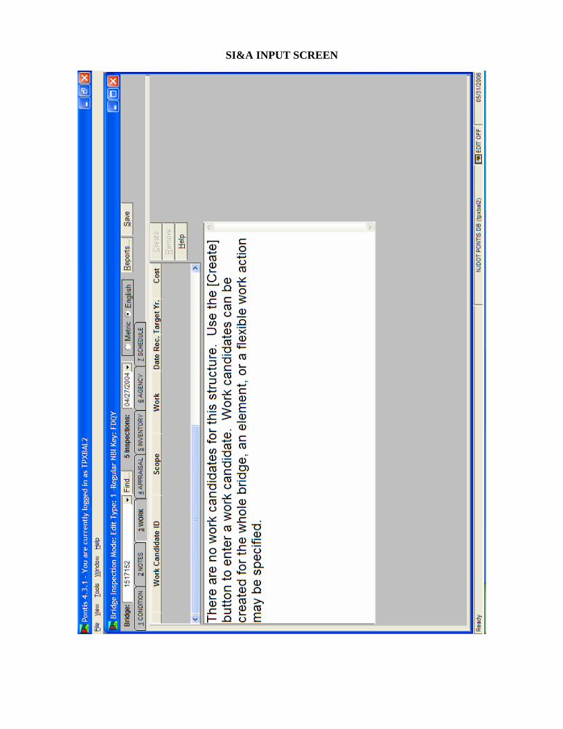
SI&A INPUT SCREEN

SI&A INPUT SCREEN

SI&A INPUT SCREEN

SI&A INPUT SCREEN
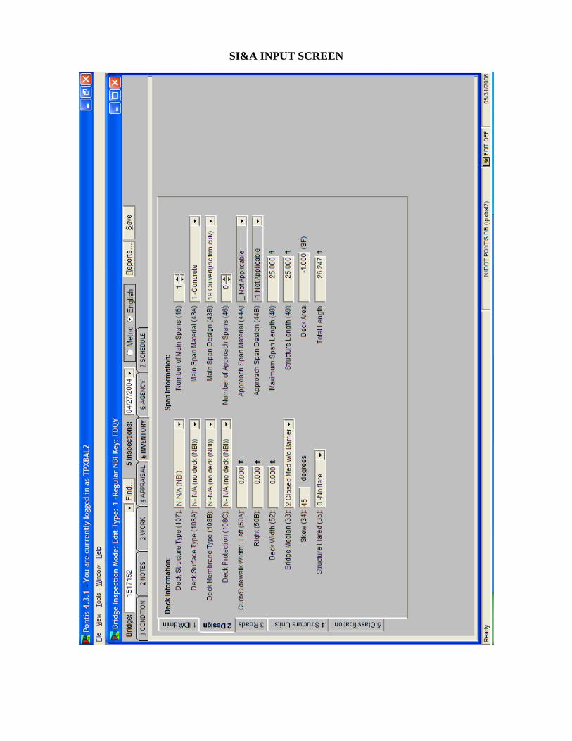
SI&A INPUT SCREEN

SI&A INPUT SCREEN
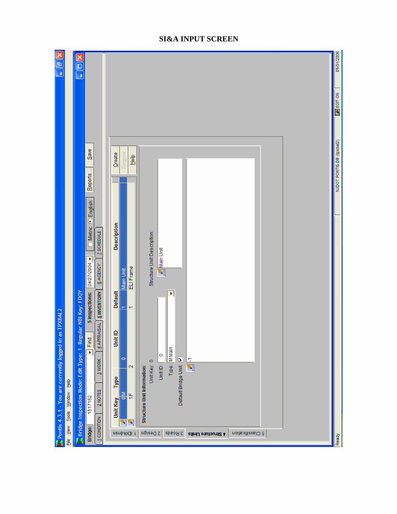
SI&A INPUT SCREEN

SI&A INPUT SCREEN

SI&A INPUT SCREEN

SI&A INPUT SCREEN

SI&A INPUT SCREEN

SI&A INPUT SCREEN


FOREWORD The Recording and Coding Guide for the Structure Inventory and Appraisal of the Nation's Bridges (Guide) has been revised several times in the past. This latest edition revises the Guide to convert all of the units of measurement to the International System of Units. This revised Guide represents several years of effort by the Federal Highway Administration with the States' cooperation and comments, both individually and through the AASHTO Subcommittee on Bridges and Structures. Initial distribution of the Guide is being made directly to each FHWA field office for distribution to the States. Additional copies are available from the Bridge Management Branch (HNG-33) of the FHWA Bridge Division.
William A. Weseman, Director Office of Engineering
NOTE: This Coding Guide has been converted to English Units
for use in New Jersey
Under the Paper Work Reduction Act and CFR 1320 the Structure Inventory and Appraisal Sheet reporting requirements have been cleared by OMB under 2125-0501.

RECORDING AND CODING GUIDE FOR THE STRUCTURE INVENTORY AND APPRAISAL OF THE NATION'S BRIDGES _________________________________________________________________ Report No. FHWA-PD-96-001
Prepared by Office of Engineering Bridge Division Bridge Management Branch Washington, D.C. 20590 December 1995

TABLE OF CONTENTS INTRODUCTION PAGE DEFINITION OF TERMS vii ix DATA ITEMS 1 State Code F1 2 Highway Agency District F1 3 County (Parish) Code F2 4 Place Code F2 5 Inventory Route F2 6 Features Intersected F5 7 Facility Carried by Structure F6 8 Structure Number F6 9 Location F7 10 Inventory Route, Minimum Vertical Clearance F7 11 Mile Point F8 12 Base Highway Network F8 13 LRS Inventory Route, Subroute Number F9 14 (Reserved) F9 15 (Reserved) F9 16 Latitude F10 17 Longitude F10 18 (Reserved) F11 19 Bypass, Detour Length F11 20 Toll F13 21 Maintenance Responsibility F14 22 Owner F15 23 (Reserved) F15 24 (Reserved) F15 25 (Reserved) F15 26 Functional Classification of Inventory Route F15 27 Year Built F16 28 Lanes On and Under the Structure F16 29 Average Daily Traffic F17 30 Year of Average Daily Traffic F18 31 Design Load F18 32 Approach Roadway Width F19 33 Bridge Median F20 34 Skew F21
iii

DATA ITEMS PAGE 35 Structure Flared F21 36 Traffic Safety Features F21 37 Historical Significance F23 38 Navigation Control F24 39 Navigation Vertical Clearance F25 40 Navigation Horizontal Clearance F25 41 Structure Open, Posted, or Closed to Traffic F26 42 Type of Service F26 43 Structure Type, Main F28 44 Structure Type, Approach Spans F29 45 Number of Spans in Main Unit F30 46 Number of Approach Spans F30 47 Inventory Route, Total Horizontal Clearance F30 48 Length of Maximum Span F32 49 Structure Length F32 50 Curb or Sidewalk Widths F35 51 Bridge Roadway Width, Curb-to-Curb F37 52 Deck Width, Out-to-Out F38 53 Minimum Vertical Clearance Over Bridge Roadway F38 54 Minimum Vertical Underclearance F38 55 Minimum Lateral Underclearance on Right F40 56 Minimum Lateral Underclearance on Left F42 57 (Reserved) F42 -- Condition Ratings F42 58 Deck F43 59 Superstructure F44 60 Substructure F44 61 Channel and Channel Protection F45 62 Culverts F46 63 Method Used to Determine Operating Rating F47 64 Operating Rating F47 65 Method Used to Determine Inventory Rating F49 66 Inventory Rating F49 -- Appraisal Ratings F49 67 Structural Evaluation F50 68 Deck Geometry F52 69 Underclearances, Vertical and Horizontal F56 70 Bridge Posting F59 71 Waterway Adequacy F60 72 Approach Roadway Alignment F61 73 (Reserved) F62
iv

DATA ITEMS PAGE 74 (Reserved) F62 75 Type of Work F62 76 Length of Structure Improvement F64 77 (Reserved) F66 78 (Reserved) F66 79 (Reserved) F66 80 (Reserved) F66 81 (Reserved) F66 82 (Reserved) F66 83 (Reserved) F66 84 (Reserved) F66 85 (Reserved) F66 86 (Reserved) F66 87 (Reserved) F66 88 (Reserved) F66 89 (Reserved) F66 90 Inspection Date F66 91 Designated Inspection Frequency F66 92 Critical Feature Inspection F67 93 Critical Feature Inspection Date F68 94 Bridge Improvement Cost F68 95 Roadway Improvement Cost F69 96 Total Project Cost F69 97 Year of Improvement Cost Estimate F70 98 Border Bridge F70 99 Border Bridge Structure Number F71 100 STRAHNET Highway Designation F71 101 Parallel Structure Designation F72 102 Direction of Traffic F72 103 Temporary Structure Designation F73 104 Highway System of the Inventory Route F74 105 Federal Lands Highways F74 106 Year Reconstructed F74 107 Deck Structure Type F75 108 Wearing Surface/Protective System F75 109 Average Daily Truck Traffic F77 110 Designated National Network F77 111 Pier or Abutment Protection (for Navigation) F77 112 NBIS Bridge Length F78 113 Scour Critical Bridges F80
v
DATA ITEMS PAGE 114 Future Average Daily Traffic F83 115 Year of Future Average Daily Traffic F83 116 Minimum Navigation Vertical Clearance F83 Vertical Lift Bridge GENERAL F84 APPENDIX A Structure Inventory and Appraisal Sheet FA-1 APPENDIX B Sufficiency Rating Formula and Example FB-1 to FB13 APPENDIX C National Bridge Inspection Standards FC-1 to FC-4 APPENDIX D Commentary FD-1 to FD-9
vi

INTRODUCTION The Recording and Coding Guide for the Structure Inventory and Appraisal of the Nation's Bridges, hereafter referred to as the Guide, has been revised several times in the past. It also provides more thorough and detailed guidance in evaluating and coding specific bridge data. New items have been added to include the reporting of Federal Lands Highway Systems, each State's existing linear referencing system (LRS), and the method used to determine the load ratings. Some items in the Guide have also been expanded to provide more definitive and explicit explanations and instructions for coding. Further, more basic definitions applicable to the instructions in the Guide are provided. The changes are based on comments received on the previous Guide and the metric version (January 1994) draft Guide. This revised Guide should be thoroughly reviewed by each individual involved with the National Bridge Inspection Program. This Guide has been prepared for use by the States, Federal and other agencies in recording and coding the data elements that will comprise the National Bridge Inventory data base. By having a complete and thorough inventory, an accurate report can be made to the Congress on the number and state of the Nation's bridges. The Guide also provides the data necessary for the Federal Highway Administration (FHWA) and the Military Traffic Management Command to identify and classify the Strategic Highway Corridor Network and it's connectors for defense purposes. The coded items in this Guide are considered to be an integral part of the data base that can be used to meet several Federal reporting requirements, as well as part of the States' needs. These requirements are set forth in the National Bridge Inspection Standards (23 CFR 650.3) which are included as Appendix C. A complete, thorough, accurate, and compatible data base is the foundation of an effective bridge management system. Reports submitted in connection with the Highway Bridge Replacement and Rehabilitation Program and the National Bridge Inspection Program also are related to this Guide. The AASHTO Manual for Condition Evaluation of Bridges discusses the various items of information that are to be recorded as part of original bridge reports. That manual and the Bridge Inspector's Training Manual/90, with supplements, discuss inspection procedures and the preparation of detailed reports about the structure components. These reports will be the basis for recording values for many of the data elements shown in the Guide, particularly those having to do with the condition or the appraisal ratings.
vii

Some bridge owners are collecting bridge condition ratings for items included in this Guide (Items 58-Deck, 59-Superstructure, 60-Substructure, and 62-Culvere) using the American Association of Highway and Transportation Officials' (AASHTO) Guide for Commonly Recognized (CoRe) Structural Elements. CoRe element inspection ratings provide detailed condition assessments that can serve as input into a comprehensive bridge management system (BMS). The FHWA has provided bridge owners with a computer program for translating bridge condition data in the CoRe element format to National Bridge Inventory (NBI) condition ratings for the purpose of NBI data submittal to FHWA. The purpose of the program is to permit bridge inspectors to record condition information in a format that satisfies both BMS and NBI data collection requirements. The Structure Inventory and Appraisal (SI&A) Sheet and the sufficiency rating formula, with examples, are included as Appendices A and B, respectively. The SI&A sheet is intended to be a tabulation of the pertinent elements of information about an individual structure. Its use is optional, subject to the statements in the preceding paragraph of this Introduction. It is important to note that the SI&A Sheet is not an inspection form but merely a summary sheet of bridge data required by the FHWA to effectively monitor and manage a National bridge program. States, Federal and other agencies are encouraged to use the codes and instructions in this Guide. However, its direct use is optional; each agency may use its own code scheme provided that the data are directly translatable into the Guide format. When data are requested by FHWA, the format will be based on the codes and instructions in this Guide. An agency choosing to use its own codes shall provide for translation or conversion of its own codes into those used in the Guide. In other words, agencies are responsible for having the capability to obtain, store, and report certain information about bridges whether or not this Guide or the SI&A Sheet is used. Any requests by the FHWA for submittals of these data will be based on the definitions, explanations, and codes supplied in the Guide, the AASHTO Manual for Condition Evaluation of Bridges and the Bridge Inspector's Training Manual/90 plus supplements. The values provided in the tables or otherwise listed in this Guide are for rating purposes only. Current design standards must be used for structure design or rehabilitation. All possible combinations of actual site characteristics are not provided in this Guide. If a special situation not listed in the Guide is encountered, the evaluation criteria closest to the actual site situation should be used. The implementation of this Guide may require some restructuring of an agency's data base and support software. If so, it is suggested that the agency consider the additional enhancements that would be necessary to support a bridge management system. Appendix D is a Commentary that compares, item by item, the 1988 Guide to this Guide. The Commentary will provide a ready reference for item changes. NOTE: This Coding Guide has been converted to English Units where
possible for use in New Jersey. All revisions to the Guide due to this conversion are shown in italics.
viii

DEFINITION OF TERMS
The definitions of terms used in the Guide are provided below. (a) Bridge. The National Bridge Inspection Standards published in the Code of Federal
Regulations (23 CFR 650.3) give the following definition: A structure including supports erected over a depression or an obstruction, such as water,
highway, or railway, and having a track or passageway for carrying traffic or other moving loads, and having an opening measured along the center of the roadway of more than 20 feet* between undercopings of abutments or spring lines of arches, or extreme ends of openings for multiple boxes; it may also include multiple pipes, where the clear distance between openings is less than half of the smaller contiguous opening.
* (6.1 meters) (b) Culvert. A structure designed hydraulically to take advantage of submergence to increase
hydraulic capacity. Culverts, as distinguished from bridges, are usually covered with embankment and are composed of structural material around the entire perimeter, although some are supported on spread footings with the streambed serving as the bottom of the culvert. Culverts may qualify to be considered "bridge" length.
(c) Inventory Route. The route for which the applicable inventory data is to be recorded.
The inventory route may be on the structure or under the structure. Generally inventories along a route are made from west to east and south to north.
(d) National Bridge Inventory (NBI). The aggregation of structure inventory and appraisal
data collected to fulfill the requirements of the National Bridge Inspection Standards. Each State shall prepare and maintain an inventory of all bridges subject to the NBIS.
(e) National Bridge Inventory (NBI) Record. Data which has been coded according to the
Guide for each structure carrying highway traffic or each inventory route which goes under a structure. These data are furnished and stored in a compact alphanumeric format on magnetic tapes or disks suitable for electronic data processing.
(f) National Bridge Inspection Standards (NBIS). Federal regulations establishing
requirements for inspection procedures, frequency of inspections, qualifications of personnel, inspection reports, and preparation and maintenance of a State bridge inventory. The NBIS apply to all structures defined as bridges located on all public roads.
(g) Public Road. Any road under the jurisdiction of and maintained by a public authority and
open to public travel.
ix

(h) Structure Inventory and Appraisal (SI&A) Sheet. The graphic representation of the data recorded and stored for each NBI record in accordance with this Guide.
(i) Strategic Highway Corridor Network (STRAHNET). A system of highways which are
strategically important to the defense of the United States. It includes the Interstate Highways and 15,669 miles of other non-interstate highways. The Military Traffic Management Command Report SE 89-4b-27, Strategic Highway Corridor Network, January 1991, contains additional information on STRAHNET.
(j) STRAHNET Connectors are roads that connect military installations and ports of
embarkation to the STRAHNET. The connector routes represent about 1,890 miles of roads that complement STRAHNET.
(k) Indian Reservation Road (IRR). A public road that is located within or provides access to
an Indian reservation as described in Title 23, U.S.C., Sect.101. The terminus of a road providing access to an Indian reservation or other Indian land is defined as the point at which the road intersects with a road functionally classified as a collector or higher classification (outside the reservation boundary) in both urban and rural areas. In the case of access from an Interstate Highway, the terminus is the first interchange outside the reservation.
(l) Land Management Highway System (LMHS). Consists of adjoining state and local
public roads that provide major public access to Bureau of Land Management administered public lands, resources, and facilities.
(m) Forest Highway (FH). A road, under the jurisdiction of, and maintained by, a public
authority and open to public travel; wholly or partly within, or adjacent to, and serving the National Forest System (NFS) and which is necessary for the protection, administration, and utilization of the NFS and the use and development of its resources. (23 CFR 660).
(n) Forest Service Development Road. A forest road wholly under the jurisdiction of the
Forest Service, which may be "open to public travel". Bridges on Forest Service Development Roads which are "open to public travel" are subject to the NBIS.
(o) Base Highway Network. The Base Highway Network includes the through lane
(mainline) portions of the NHS, rural/urban principal arterial system and rural minor arterial system. Ramps, frontage roads and other roadways are not included in the Base Network.
x

(p) Highway Performance Monitoring System. The Highway Performance Monitoring
System (HPMS) is a database of universe and sample data that describes the nation's public road mileage. The data are annually updated and submitted to FHWA by the State Highway Agencies, Puerto Rico and the District of Columbia. The universe data provides some basic characteristics of all public road mileage while the sample of the arterial and collector systems allows for assessment of the condition, performance, usage and additional characteristics of the nation's major highway systems.
(q) Conversion of Numerical Data. Throughout this Guide the following conversion factors
are used: Convert - foot to meter multiply by 0.3048 - mile to kilometer multiply by 1.609 - english ton to metric ton multiply by .9 (r) Rounding and Truncating of Numerical Data. All numeral values in this Guide, except as
specifically noted, will follow standard rounding criteria, that is, 5 and above will be rounded up to the next higher unit and 4 and below will be rounded down to the next lower unit. This is applicable to all decimal roundings. In certain items where rounding may cause a safety hazard for clearance, the numeric measurements will be truncated at the appropriate decimal place. This means that a fractional portion less than a whole unit will be dropped to the lower whole number, for example 2.88 would be truncated to 2.8 when using tenth of a foot accuracy. All decimal points are assumed in the locations as specified in the Guide.
(s) Commonly Recognized (CoRe) Structural Elements). A group of structural elements
endorsed by AASHTO as a means of providing a uniform basis for data collection for any bridge management system, to enable the sharing of data between States, and to allow for a uniform translation of data to NBI Items 58, 59, 60 and 62.
(t) Bridge Management System (BMS). A system designed to optimize the use of available
resources for the inspection, maintenance, rehabilitation and replacement of bridges.
xi

DATA ITEMS
ITEM 1 - STATE CODE 3 DIGITS The first 2 digits are the Federal Information Processing Standards (FIPS) code for States, and the third digit is the FHWA region code. (New Jersey and New York will retain an FHWA region code of 2.)
Code State Code State 014 Alabama 308 Montana 020 Alaska 317 Nebraska 049 Arizona 329 Nevada 056 Arkansas 331 New Hampshire 069 California 342 New Jersey 088 Colorado 356 New Mexico 091 Connecticut 362 New York 103 Delaware 374 North Carolina 113 District of Columbia 388 North Dakota 124 Florida 395 Ohio 134 Georgia 406 Oklahoma 159 Hawaii 410 Oregon 160 Idaho 423 Pennsylvania 175 Illinois 441 Rhode Island 185 Indiana 454 South Carolina 197 Iowa 468 South Dakota 207 Kansas 474 Tennessee 214 Kentucky 486 Texas 226 Louisiana 498 Utah 231 Maine 501 Vermont 243 Maryland 513 Virginia 251 Massachusetts 530 Washington 265 Michigan 543 West Virginia 275 Minnesota 555 Wisconsin 284 Mississippi 568 Wyoming 297 Missouri 721 Puerto Rico
ITEM 2 - HIGHWAY AGENCY DISTRICT 2 DIGITS The highway agency district (State or Federal) in which the bridge is located shall be represented by a 2-digit code. Existing district numbers shall be used where districts are identified by number. Where districts are identified by name, a code number shall be assigned based on an alphabetical or organizational listing of the districts. NOTE: Refer to page SA-1 of this Guide for additional information.
F1 ITEM 3 - COUNTY (PARISH) CODE 3 DIGITS

Counties shall be identified using the Federal Information Processing Standards (FIPS) codes given in the current version of the Census of Population and Housing - Geographic Identification Code Scheme. NOTE: Refer to page SA-1 of this Guide for additional information. ITEM 4 - PLACE CODE 5 DIGITS Cities, towns, townships, villages, and other census-designated places shall be identified using the Federal Information Processing Standards (FIPS) codes given in the current version of the Census of Population and Housing - Geographic Identification Code Scheme. If there is no FIPS place code, then code all zeros. NOTE: Refer to page SA-1 of this Guide for additional information. ITEM 5 - INVENTORY ROUTE 9 DIGITS The inventory route is a 9-digit code composed of 5 segments.
Segment Description Length 5A Record Type 1 digit 5B Route Signing Prefix 1 digit 5C Designated Level of Service 1 digit 5D Route Number 5 digits 5E Directional Suffix 1 digit
ITEM 5A - RECORD TYPE 1 DIGIT There are two types of National Bridge Inventory records: "on" and "under". Code the first digit (leftmost) using one of the following codes:
Code Description 1 Route carried "on" the structure 2 Single route goes "under" the structure A through Z Multiple routes go "under" the structure
A signifies the first of multiple routes under the structure. B signifies the second of multiple routes under the structure. Z signifies 26 routes under the structure.
F2 ITEM 5A - RECORD TYPE (CONTINUED)

"On" signifies that the inventory route is carried "on" the structure. Each bridge structure carrying highway traffic must have a record identified with a type code = 1 (numeric). All of the NBI data items must be coded, unless specifically excepted, with respect to the structure and the inventory route "on" it. "Under" signifies that the inventory route goes "under" the structure. If an inventory route beneath the structure is a Federal-aid highway, is a STRAHNET route or connector or is otherwise important, a record must be coded to identify it. The type code must be 2 or an alphabetic letter A through Z. Code 2 for a single route under the structure. If 2 or more routes go under a structure on separate roadways, the code of 2 shall not be used. Code A, B, C, D, etc. consecutively for multiple routes on separate roadways under the same structure. STRAHNET routes shall be listed first. When this item is coded 2 or A through Z, only the following items must be coded: Items 1, 3-13, 16, 17, 19, 20, 26-30, 42, 43, 47-49, 100-104, 109 and 110. All other items may remain blank. It cannot be overemphasized that all route-oriented data must agree with the coding as to whether the inventory route is "on" or "under" the structure. Tunnels shall be coded only as an "under" record; that is, they shall not be coded as a structure carrying highway traffic. There are situations of a route "under" a structure, where the structure does not carry a highway, but may carry a railroad*, pedestrian traffic, or even a building. These are coded the same as any other "under" record and no "on" record shall be coded. *For State owned railroad carrying bridges, code Item 5A = “1” on Sheet 1 (see Railroad Bridge Coding Instructions) ITEM 5B - ROUTE SIGNING PREFIX 1 DIGIT In the second position, identify the route signing prefix for the inventory route using one of the following codes:
Code Description 1 Interstate highway 2 U.S. numbered highway 3 State highway 4 County highway 5 City street 6 Federal lands road 7 State lands road 8 Other (include toll roads not otherwise indicated or identified above)
When 2 or more routes are concurrent, the highest class of route will be used. The hierarchy is in the order listed above.
F3 ITEM 5C - DESIGNATED LEVEL OF SERVICE 1 DIGIT

In the third position, identify the designated level of service for the inventory route using one of the following codes:
Code Description 0 None of the below 1 Mainline 2 Alternate 3 Bypass 4 Spur 6 Business 7 Ramp, Wye, Connector, etc. 8 Service and/or unclassified frontage road
ITEM 5D - ROUTE NUMBER 5 DIGITS Code the route number of the inventory route in the next 5 positions. This value shall be right justified in the field with leading zeros filled in. (See examples below.) If concurrent routes are of the same hierarchy level, denoted by the route signing prefix, the lowest numbered route shall be coded. Code 00000 for bridges on roads without route numbers. ITEM 5E - DIRECTIONAL SUFFIX 1 DIGIT In the last position, code the directional suffix to the route number of the inventory route when it is part of the route number, using one of the following codes:
Code Description 0 Not applicable 1 North 2 East 3 South 4 West
F4 ITEM 5E - DIRECTIONAL SUFFIX (CONTINUED)

In some cases, letters may be used with route numbers and as part of the route numbers and not to indicate direction. In such cases, the letter should be included in the 5-position route number field. Examples:
Record
Code
Interstate 95, on Interstate 70S, under
1 1 1 00095 0 2 1 1 00070 3
111000950 211000703
State Highway 104, Spur, under 2 3 4 00104 0 234001040
U.S. 30E Bypass, on 1 2 3 00030 2 123000302
City street, on Ramp from I-81, under
1 5 0 00000 0 2 1 7 00081 0
150000000 217000810
County Highway 173 on Interstate 84 under
1 4 1 00173 0 2 1 1 00084 0
141001730 211000840
Interstate 495 on State Hwy 120 (STRAHNET Rte) under Alternate State Hwy 130 under
1 1 1 00495 0 A 3 1 00120 0 B 3 2 00130 0
111004950 A31001200 B32001300
Tunnel on Interstate 70 2 1 1 00070 0 211000700 ITEM 6 - FEATURES INTERSECTED 25 DIGITS This item contains a description of the features intersected by the structure. When Item 5A indicates an "under" record, this item describes the inventory route and/or features under the structure. There are 25 digits divided into 2 segments.
Segment Description Length
6A Features Intersected 24 digits 6B No Longer Coded (Blank) 1 digit
F5
ITEM 6 - FEATURES INTERSECTED
The information to be recorded for this item in the first 24 digits shall be the name or names of the features intersected by the structure. When one of the features intersected is another highway, the signed number or name of the highway shall appear first (leftmost) in the field. The names of any other features shall follow, separated by a semicolon or a comma. Parentheses shall be used to provide a second identification of the same feature (see third example). Abbreviations may be used where necessary, but an effort shall be made to keep them meaningful. The data in this segment shall be left justified in the first 24 positions without trailing zeros. Examples: I 81, US 51, MILL ROAD MISSISSIPPI RIVER SR 42 (POND ROAD) ITEM 7 - FACILITY CARRIED BY STRUCTURE 18 DIGITS The facility being carried by the structure shall be recorded and coded. In all situations this item describes the use "on" the structure. This item shall be left justified without trailing zeros. Examples: US 66 MAIN STREET COUNTY ROAD 450 C & O RAILROAD (appropriate for "under" record only) PEDESTRIAN BRIDGE (appropriate for "under" record only) ITEM 8 - STRUCTURE NUMBER 15 DIGITS It is required that the official structure number be recorded. It is not necessary to code this number according to an arbitrary national standard. Each agency should code the structure number according to its own internal processing procedures. When recording and coding for this item and following items, any structure or structures with a closed median should be considered as one structure, not two. Closed medians may have either mountable or non-mountable curbs or barriers.
F6

ITEM 8 - STRUCTURE NUMBER (CONTINUED) The structure number must be unique for each bridge within the State, and once established should preferably never change for the life of the bridge. If it is essential that structure number(s) must be changed, all 15 digits are to be filled. For any structure number changes, a complete cross reference of corresponding "old" and "new" numbers must be provided to the FHWA Bridge Division. The cross reference shall include both a computer tape or diskette and a printed listing in the FHWA required format. The identical structure number must appear on the "on" and all "under" records associated with a particular structure. (Refer to Item 5 - Inventory Route). NOTE: In New Jersey, a seven (7) digit Structure Number is used. Refer to page SA-2 of this Guide for additional information. ITEM 9 - LOCATION 25 DIGITS This item contains a narrative description of the bridge location. It is recommended that the location be keyed to a distinguishable feature on an official highway department map such as road junctions and topographical features. This item shall be left justified without trailing zeros. Examples: 6 miles SW. OF RICHMOND 3.5 miles S. OF JCT. SR 69 ITEM 10 - INVENTORY ROUTE, MINIMUM VERTICAL CLEARANCE 4 DIGITS (XX.XX feet) Code the minimum vertical clearance over the inventory route identified in Item 5, whether the route is "on" the structure or "under" the structure. The minimum clearance for a 10-foot width of the pavement or traveled part of the roadway where the clearance is the greatest shall be recorded and coded in decimal feet. For structures having multiple openings, clearance for each opening shall be recorded, but only the greatest of the "minimum clearances" for the two or more openings shall be coded regardless of the direction of travel. This would be the practical maximum clearance. When no restriction exists or when the restriction is 99 feet or greater, code 9999.
F7

ITEM 11 - MILEPOINT (XXXX.XXX) 7 DIGITS The linear referencing system (LRS) milepoint is used to establish the location of the bridge on the Base Highway Network (see Item 12). It must be from the same LRS Inventory Route and milepoint system as reported in the Highway Performance Monitoring System (HPMS). The milepoint coded in this item directly relates to Item 13 - LRS Inventory Route, Subroute Number. This item must be coded for all structures located on or overpassing the Base Highway Network. Code a 7-digit number to represent the LRS mile-point distance in miles to the nearest thousandth (with an assumed decimal point). For structures carrying the LRS Inventory Route, code the milepoint at the beginning of the structure (i.e. the lowest mile-point on the bridge). When the LRS Inventory Route goes under the structure (Item 5A coded 2 or A-Z), then code the milepoint on the underpassing route where the structure is first encountered. Code all zeros in this field for all records where milepoints are not provided. Milepoints may be coded for bridges that are not located on the Base Highway Network, however Item 12 - Base Highway Network shall be coded 0 for these records. The milepoint is coded aligned to the assumed decimal point and zero filled where needed to fill the 7 digits. Examples: Code Milepoint is 130.34 0130340 Milepoint is 9.60 0009600 ITEM 12 - BASE HIGHWAY NETWORK 1 DIGIT This item is to be coded for all records in the inventory. The Base Highway Network includes the through lane (mainline) portions of the NHS, rural/urban principal arterial system and rural minor arterial system. Ramps, frontage roads and other roadways are not included in the Base Network. For the inventory route identified in Item 5 - Inventory Route, indicate whether the inventory route is on the Base Highway Network or not on that network. Use one of the following codes:
Code Description 0 Inventory Route is not on the
Base Network 1 Inventory Route is on the Base
Network
F8

ITEM 13 - LRS INVENTORY ROUTE, SUBROUTE NUMBER 12 DIGITS If Item 12 - Base Highway Network has been coded 1, the information to be recorded for this item is inventory route for the State's linear referencing system (LRS). If Item 12 has been coded 0, this entire item should be left blank. This item is a 12-digit code composed of 2 segments.
Segment Description Length 13A LRS Inventory Route 10 digits 13B Subroute Number 2 digits
The LRS inventory route and subroute numbers to be reported in this item must correspond to the LRS inventory route and subroute numbers reported by the State for the HPMS. The LRS inventory route number is coded in the ten positions of segment 13A, left justified and underscore filled. The subroute number, if it exists, is coded in the two positions of segment 13B, left justified and zero filled (not used in New Jersey). The LRS inventory route number can be alphanumeric, but must not contain blanks. The LRS inventory route number is not necessarily the same as that posted along the roadway, but is a number used to uniquely identify a route within at least a county and perhaps throughout the State. The subroute number is a number that uniquely identifies portions of an inventory route sections where duplicate milepoints occur. These subroute numbers, if they exist, are identified in the State's HPMS-LRS records. If there is no subroute number, code 00 in this segment. NOTE: The coding for the LRS is available from the Straight Line Diagram listed as a ten (10) digit number under “SRI” at the bottom of each diagram. The last two (2) digits are typically underbars. Example: Route 1 Code: 00000001_ _00 US Route 1B Code: 00000001B_00 NJ Rt. 27 SB Code: 00000027_S00 Essex County Rt. 630 A Code: 07000630A_00 ITEM 14 AND ITEM 15 (Reserved)
F9

ITEM 16 - LATITUDE (XX degrees XX minutes XX.XX seconds) 8 DIGITS For bridges on STRAHNET and STRAHNET Connector highways and on the NHS, record and code the latitude of each in degrees, minutes and seconds to the nearest hundredth of a second (with an assumed decimal point). The point of the coordinate may be the beginning of the bridge in the direction of the inventory or any other consistent point of reference on the bridge which is compatible with the LRS. If the bridge is not on a STRAHNET highway or the NHS, a code of all zeros is acceptable, but it is preferable to code the latitude if available. NOTE: Always code the Latitude for bridges in New Jersey. The reason for the increased precision is to facilitate the use of Global Positioning System (GPS) data directly into this item. The increased precision is not currently mandatory and, if GPS readings are not available, the current measuring methods and level of precision may continue to be used. The minimum precision should be to the nearest minute, but the preferred precision is to the nearest hundredth of a second using GPS methods. Example: Code Latitude is 35°27.3' (current precision) 35271800 (acceptable coding) 35270000 35°27'18.55" (GPS reading) 35271855 ITEM 17 - LONGITUDE (XXX degrees XX minutes XX.XX seconds) 9 DIGITS For bridges on STRAHNET and STRAHNET Connector highways and on the NHS, record and code the longitude of each in degrees, minutes and seconds to the nearest hundredth of a second (with an assumed decimal point). A leading zero shall be coded where needed. The point of the coordinate may be the beginning of the bridge in the direction of the inventory or any other consistent point of reference on the bridge which is compatible with the LRS. If the bridge is not on a STRAHNET highway or the NHS, a code of all zeros is acceptable, but it is preferable to code the longitude if available. NOTE: Always code the Longitude for bridges in New Jersey.
F10

ITEM 17 - LONGITUDE (CONTINUED) The reason for the increased precision is to facilitate the use of Global Positioning System (GPS) data directly into this item. The increased precision is not currently mandatory and, if GPS readings are not available, the current measuring methods and level of precision may continue to be used. The minimum precision should be to the nearest minute, but the preferred precision is to the nearest hundredth of a second using GPS methods. Example: Code Longitude is 81°5.8' (current precision) 081054800 (acceptable coding) 081060000 81°5'50.65" (GPS reading) 081055065 ITEM 18 (reserved) ITEM 19 - BYPASS, DETOUR LENGTH (XX miles) 2 DIGITS Indicate the actual length to the nearest mile of the detour length. The detour length should represent the total additional travel for a vehicle which would result from closing of the bridge. The factor to consider when determining if a bypass is available at the site is the potential for moving vehicles, including military vehicles, around the structure. This is particularly true when the structure is in an interchange. For instance, a bypass likely would be available in the case of diamond interchanges, interchanges where there are service roads available, or other interchanges where the positioning and layout of the ramps is such that they could be used without difficulty to get around the structure. If a ground level bypass is available at the structure site for the inventory route, record and code the detour length as 00. If the bridge is one of twin bridges and is not at an interchange, code 01 where the other twin bridge can be used as a temporary bypass with a reasonable amount of crossover grading. The detour route will be established following allowable criteria determined by the governing authority. (Some authorities will not allow a designated detour over a road or bridge of lesser "quality.") Code 99 for 99 miles or more.
F11

ITEM 19 - BYPASS, DETOUR LENGTH (XX miles) Examples: Code Diamond interchange, structure bypassable 00 Cloverleaf, not bypassable; 18-mile detour 18 Structure over river; 121-mile detour 99 Structure over highway, no interchange, bypassable at ground level 00 Structure on dead end road 99
Bypass, Detour Length A to B = 4 miles
Bypass, Detour Length A to B = 0 miles
F12

ITEM 20 - TOLL 1 DIGIT The toll status of the structure is indicated by this item. Interstate toll segments under Secretarial Agreement (Title 23 - United States Code - Highways Section 129 as amended by 1991 ISTEA and prior legislation) shall be identified separately. Use one of the following codes:
Code Description
1 Toll bridge. Tolls are paid specifically to use the structure.
2 On toll road. The structure carries a toll road, that is, tolls are paid to use the facility, which includes both the highway and the structure.
3 On free road. The structure is toll-free and carries a toll-free highway.
4 On Interstate toll segment under Secretarial Agreement. Structure functions as a part of the toll segment.
5 Toll bridge is a segment under Secretarial Agreement. Structure is separate agreement from highway segment.
F13 ITEM 21 - MAINTENANCE RESPONSIBILITY 2 DIGITS

The actual name(s) of the agency(s) responsible for the maintenance of the structure shall be recorded on the inspection form. The codes below shall be used to represent the type of agency that has primary responsibility for maintaining the structure. If more than one agency has equal maintenance responsibility, code one agency in the hierarchy of State, Federal, county, city, railroad, and other private.
Code Description 01 State Highway Agency 02 County Highway Agency 03 Town or Township Highway Agency 04 City or Municipal Highway Agency 11 State Park, Forest, or Reservation Agency 12 Local Park, Forest, or Reservation Agency 21 Other State Agencies 25 Other Local Agencies 26 Private (other than railroad) 27 Railroad 31 State Toll Authority 32 Local Toll Authority 60 Other Federal Agencies (not listed below) 61 Indian Tribal Government 62 Bureau of Indian Affairs 63 Bureau of Fish and Wildlife 64 U.S. Forest Service 66 National Park Service 67 Tennessee Valley Authority 68 Bureau of Land Management 69 Bureau of Reclamation 70 Corps of Engineers (Civil) 71 Corps of Engineers (Military) 72 Air Force 73 Navy/Marines 74 Army 75 NASA 76 Metropolitan Washington Airports Service 80 Unknown
F14
ITEM 22 - OWNER 2 DIGITS

The actual name(s) of the owner(s) of the bridge shall be recorded on the inspection form. The codes used in Item 21 - Maintenance Responsibility shall be used to represent the type of agency that is the primary owner of the structure. If more than one agency has equal ownership, code one agency in the hierarchy of State, Federal, county, city, railroad, and other private. ITEM 23 THROUGH ITEM 25 (Reserved) ITEM 26 - FUNCTIONAL CLASSIFICATION OF INVENTORY ROUTE 2 DIGITS For the inventory route, code the functional classification using one of the following codes:
Code Description Rural
01 Principal Arterial - Interstate 02 Principal Arterial - Other 06 Minor Arterial 07 Major Collector 08 Minor Collector 09 Local Urban
11 Principal Arterial - Interstate 12 Principal Arterial - Other
Freeways or Expressways 14 Other Principal Arterial 16 Minor Arterial 17 Collector 19 Local
The bridge shall be coded rural if not inside a designated urban area. The urban or rural designation shall be determined by the bridge location and not the character of the roadway.
F15 ITEM 27 - YEAR BUILT 4 DIGITS

Record and code the year of construction of the structure. Code all 4 digits of the year in which construction of the structure was completed. If the year built is unknown, provide a best estimate. See also Item 106 - Year Reconstructed. Examples: Code
Construction completed 1956 1956 1892 1892 ITEM 28 - LANES ON AND UNDER THE STRUCTURE 4 DIGITS Record and code the number of lanes being carried by the structure and being crossed over by the structure as a 4-digit number composed of 2 segments. The number of lanes should be right justified in each segment with leading zero(s) coded as required.
Segment Description Length
28A Lanes on the structure 2 digits 28B Lanes under the structure 2 digits
Include all lanes carrying highway traffic (i.e., cars, trucks, buses) which are striped or otherwise operated as a full width traffic lane for the entire length of the structure or under the structure by the owning/maintaining authority. This shall include any full width merge lanes and ramp lanes, and shall be independent of directionality of usage (i.e., a 1-lane bridge carrying 2-directional traffic is still considered to carry only one lane on the structure). It should be noted here that for the purpose of evaluating the Deck Geometry - Item 68, any "1-lane" bridge, not coded as a ramp (Item 5C = 7), which has a Bridge Roadway Width, Curb-to-Curb - Item 51 coded 16 feet or greater shall be evaluated as 2 lanes. When the inventory route is "on" the bridge (the first digit of Item 5 - Inventory Route is coded 1), the sum of the total number of lanes on all inventoried routes under the bridge shall be coded. When the inventory route is "under" the bridge (the first digit of Item 5 - Inventory Route is coded 2 or A through Z), only the number of lanes being identified by that "under" record shall be coded in Item 28B. When the inventory route is "under" the structure, the obstruction over the inventory route may be other than a highway bridge (railroad, pedestrian, pipeline, etc.). Code 00 for these cases if there are no highway lanes on the obstructing structure.
F16
ITEM 28 - LANES ON AND UNDER THE STRUCTURE (CONTINUED)

Double deck bridges may be coded as 1 or 2 structures as noted in the examples on the next page. Either method is acceptable, however, all related data must be compatible with the method selected. Examples*:
Code 1 lane on, 0 lanes under 0100 3 lanes on, 1 lane under 0301 8 lanes on 2-way, 12 lanes under ** 0812 5 lanes on double deck each direction, 2 lanes under 1002*** 5 lanes on double deck each direction, 2 lanes under 0502**** Railroad and pedestrian on, 4 lanes under 0004
* For the inventory route on the bridge, the first digit of Item 5 -
Inventory Route is coded 1.
** This example has 3 inventory routes under the bridge of 6, 4, and 2 lanes of 2-way traffic respectively. When coding an "under" record for each of these inventory routes, the first digit of Item 5 - Inventory Route is coded A, B, and C, and Item 28 is coded 0806, 0804, and 0802 respectively for the 3 required records.
*** Acceptable if coded as 1 bridge. However, other data such as ADT, curb- to-curb width, etc., must be for both decks (preferred method).
**** Acceptable if coded as 2 separate bridges. However, other data such as ADT, curb-to-curb width, etc., must be for a single deck.
ITEM 29 - AVERAGE DAILY TRAFFIC 6 DIGITS Code a 6-digit number that shows the average daily traffic volume for the inventory route identified in Item 5. Make certain the unit's position is coded even if estimates of ADT are determined to tens or hundreds of vehicles; that is, appropriate trailing zeros shall be coded. The ADT coded should be the most recent ADT counts available. Included in this item are the trucks referred to in Item 109 - Average Daily Truck Traffic. If the bridge is closed, code the actual ADT from before the closure occurred.
F17
ITEM 29 - AVERAGE DAILY TRAFFIC (CONTINUED)

The ADT must be compatible with the other items coded for the bridge. For example, parallel bridges with an open median are coded as follows: if Item 28 - Lanes On and Under the Structure and Item 51 - Bridge Roadway Width, Curb-to-Curb are coded for each bridge separately, then the ADT must be coded for each bridge separately (not the total ADT for the route). Examples:
Code Average Daily Traffic 540 000540 15,600 015600 24,000 024000
ITEM 30 - YEAR OF AVERAGE DAILY TRAFFIC 4 DIGITS Record the year represented by the ADT in Item 29. Code all four digits of the year so recorded. Examples: Code Year of ADT is 1994 1994 ITEM 31 - DESIGN LOAD 1 DIGIT Use the codes below to indicate the live load for which the structure was designed. The numerical value of the railroad loading should be recorded on the form. Classify any other loading, when feasible, using the nearest equivalent of the loadings given below.
Code
Metric Description
English Description
1 M 9 or H 10 2 M 13.5 H 15 3 MS 13.5 HS 15 4 M 18 H 20 5 MS 18 HS 20 6 MS 18+Mod HS 20+Mod 7 Pedestrian Pedestrian 8 Railroad Railroad 9 MS 22.5 HS 25 0 Other or Unknown (describe on
inspection reporting form)
NOTE: Code English Description in New Jersey.
F18
ITEM 32 - APPROACH ROADWAY WIDTH (XXX feet) 3 DIGITS
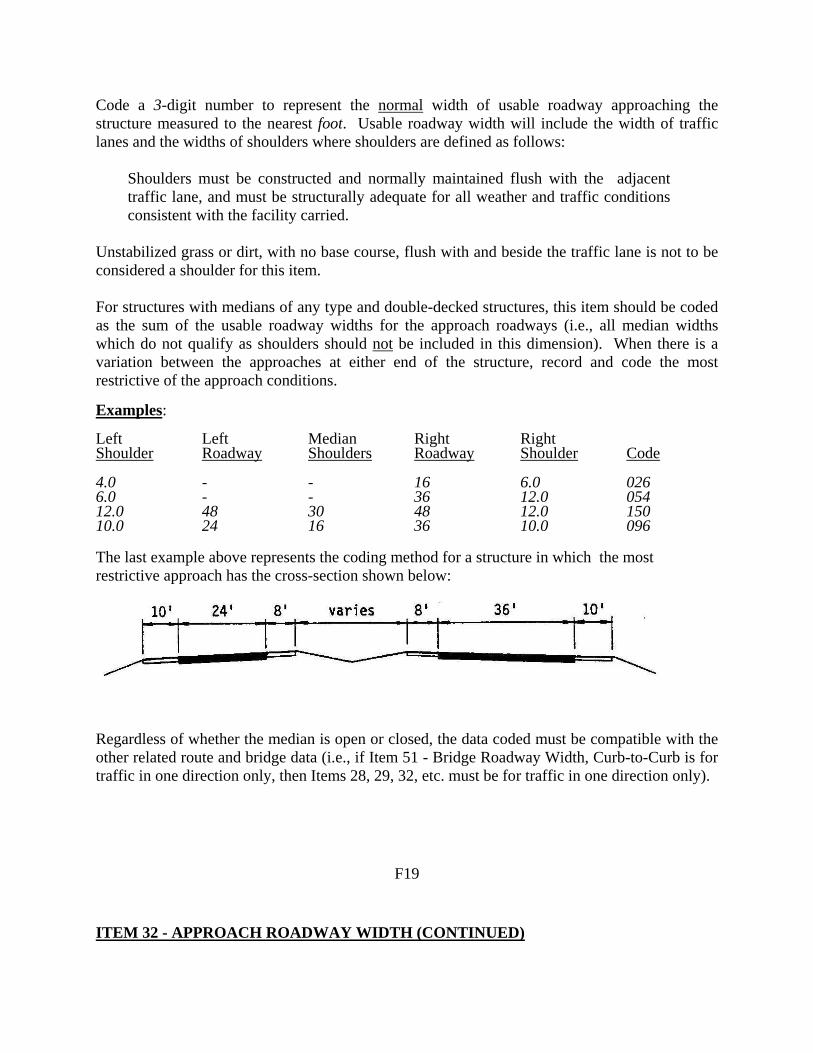
Code a 3-digit number to represent the normal width of usable roadway approaching the structure measured to the nearest foot. Usable roadway width will include the width of traffic lanes and the widths of shoulders where shoulders are defined as follows:
Shoulders must be constructed and normally maintained flush with the adjacent traffic lane, and must be structurally adequate for all weather and traffic conditions consistent with the facility carried.
Unstabilized grass or dirt, with no base course, flush with and beside the traffic lane is not to be considered a shoulder for this item. For structures with medians of any type and double-decked structures, this item should be coded as the sum of the usable roadway widths for the approach roadways (i.e., all median widths which do not qualify as shoulders should not be included in this dimension). When there is a variation between the approaches at either end of the structure, record and code the most restrictive of the approach conditions. Examples: Left Shoulder
Left Roadway
Median Shoulders
Right Roadway
Right Shoulder
Code
4.0 - - 16 6.0 026 6.0 - - 36 12.0 054 12.0 48 30 48 12.0 150 10.0 24 16 36 10.0 096 The last example above represents the coding method for a structure in which the most restrictive approach has the cross-section shown below:
Regardless of whether the median is open or closed, the data coded must be compatible with the other related route and bridge data (i.e., if Item 51 - Bridge Roadway Width, Curb-to-Curb is for traffic in one direction only, then Items 28, 29, 32, etc. must be for traffic in one direction only).
F19
ITEM 32 - APPROACH ROADWAY WIDTH (CONTINUED)

If a ramp is adjacent to the through lanes approaching the structure, it shall be included in the approach roadway width. The total approach roadway width for the example below is 94 feet (a code of 094).
ITEM 33 - BRIDGE MEDIAN 1 DIGIT Indicate with a 1-digit code if the median is non-existent, open or closed. The median is closed when the area between the 2 roadways at the structure is bridged over and is capable of supporting traffic. All bridges that carry either 1-way traffic or 2-way traffic separated only by a centerline will be coded 0 for no median.
Code Description 0 No median 1 Open median 2 Closed median (no barrier) 3 Closed median with non-mountable barriers
F20 ITEM 34 - SKEW (XX degrees) 2 DIGITS

The skew angle is the angle between the centerline of a pier and a line normal to the roadway centerline. When plans are available, the skew angle can be taken directly from the plans. If no plans are available, the angle is to be field measured if possible. Record the skew angle to the nearest degree. If the skew angle is 0, it should be so coded. When the structure is on a curve or if the skew varies for some other reason, the average skew should be recorded, if reasonable. Otherwise, record 99 to indicate a major variation in skews of substructure units. A 2-digit number should be coded. Examples:
Code Skew angle 0° 00 10° 10 8° 08 29° 29
ITEM 35 - STRUCTURE FLARED 1 DIGIT Code this item to indicate if the structure is flared (i.e., the width of the structure varies). Generally, such variance will result from ramps converging with or diverging from the through lanes on the structure, but there may be other causes. Minor flares at ends of structures should be ignored.
Code Description 0 No flare 1 Yes, flared
ITEM 36 - TRAFFIC SAFETY FEATURES 4 DIGITS Bridge inspection shall include the recording of information on the following traffic safety features so that the evaluation of their adequacy can be made. (A) Bridge railings: Some factors that affect the proper functioning of bridge railing are height,
material, strength, and geometric features. Railings must be capable of smoothly redirecting an impacting vehicle. Bridge railings should be evaluated using the current AASHTO Standard Specifications for Highway Bridges, which calls for railings to meet specific geometric criteria and to resist specified s tatic loads without exceeding the
F21
ITEM 36 - TRAFFIC SAFETY FEATURES (CONTINUED)

allowable stresses in their elements. Bridge railing should be crash tested per FHWA policy. Railings that meet these criteria and loading conditions are considered acceptable. Other railings that have been successfully crash tested are considered acceptable even though they may not meet the static loading analysis and geometric requirements. Acceptable guidelines for bridge railing design and testing are also found in the AASHTO Guide Specifications for Bridge Railings 1989. Additional guidance for testing is found in National Cooperative Highway Research Program - Report 350 Recommended Procedures for the Safety Performance Evaluation of Highway Features 1993.
(B) Transitions: The transition from approach guardrail to bridge railing requires that the
approach guardrail be firmly attached to the bridge railing. It also requires that the approach guardrail be gradually stiffened as it comes closer to the bridge railing. The ends of curbs and safety walks need to be gradually tapered out or shielded.
(C) Approach guardrail: The structural adequacy and compatibility of approach guardrail with
transition designs should be determined. Rarely does the need for a barrier stop at the end of a bridge. Thus, an approach guardrail with adequate length and structural qualities to shield motorists from the hazards at the bridge site needs to be installed. In addition to being capable of safely redirecting an impacting vehicle, the approach guardrail must also facilitate a transition to the bridge railing that will not cause snagging or pocketing of an impacting vehicle. Acceptable guardrail design suggestions are contained in the AASHTO Roadside Design Guide and subsequent FHWA or AASHTO guidelines.
(D) Approach guardrail ends: As with guardrail ends in general, the ends of approach
guardrails to bridges should be flared, buried, made breakaway, or shielded. Design treatment of guardrail ends is given in the AASHTO Roadside Design Guide.
The data collected shall apply only to the route on the bridge. Collision damage or deterioration of the elements are not considered when coding this item. Traffic safety features is a 4-digit code composed of 4 segments.
Segment Description Length
36A Bridge railings 1 digit 36B Transitions 1 digit 36C Approach guardrail 1 digit 36D Approach guardrail ends 1 digit
F22
ITEM 36 - TRAFFIC SAFETY FEATURES (CONTINUED)

The reporting of these features shall be as follows:
Code Description 0 Inspected feature does not meet currently acceptable
standards or a safety feature is required and none is provided.*
1 Inspected feature meets currently acceptable standards.*
N Not applicable or a safety feature is not required.* * For structures on the NHS, national standards are set by regulation. For those not on the
NHS, it shall be the responsibility of the highway agency (state, county, local or federal) to set standards. NOTE: For clarifications on the coding of this Item, please refer to Appendix F,
“Commentary on Item 36 (Safety Features)” in the State Coding Guide portion of this Manual.
Example: Code All features meet currently acceptable standards except transition 1011 ITEM 37 - HISTORICAL SIGNIFICANCE 1 DIGIT The historical significance of a bridge involves a variety of characteristics: the bridge may be a particularly unique example of the history of engineering; the crossing itself might be significant; the bridge might be associated with a historical property or area; or historical significance could be derived from the fact the bridge was associated with significant events or circumstances. Use one of the following codes:
Code
Description
1 Bridge is on the National Register of Historic Places.
2 Bridge is eligible for the National Register of Historic Places.
3 Bridge is possibly eligible for the National Register of Historic Places (requires further investigation before determination can be made) or bridge is on a State or local historic register.
F23
ITEM 37 - HISTORICAL SIGNIFICANCE (CONTINUED)

Code
Description
4 Historical significance is not determinable at this time.
5 Bridge is not eligible for the National Register of Historic places.
ITEM 38 - NAVIGATION CONTROL 1 DIGIT Indicate for this item whether or not navigation control (a bridge permit for navigation) is required. Use one of the following codes:
Code Description
N Not applicable, no waterway.
0 No navigation control on waterway (bridge permit not required).
1 Navigation control on waterway (bridge permit required).
NOTE: Please refer to page SA-2 of this Guide for additional instructions.
F24

ITEM 39 - NAVIGATION VERTICAL CLEARANCE (XXX feet) 3 DIGITS If Item 38 - Navigation Control has been coded 1, record the minimum vertical clearance imposed at the site as measured above a datum that is specified on a navigation permit issued by a control agency. The measurement shall be coded as a 3-digit number rounded down to the nearest foot. This measurement will show the clearance that is allowable for navigational purposes. In the case of a swing or bascule bridge, the vertical clearance shall be measured with the bridge in the closed position (i.e., open to vehicular traffic). The vertical clearance of a vertical lift bridge shall be measured with the bridge in the raised or open position. Also, Item 116 - Minimum Navigation Vertical Clearance Vertical Lift Bridge shall be coded to provide clearance in a closed position. If Item 38 - Navigation Control has been coded 0 or N, code 000 to indicate not applicable. Examples:
Code
Measured Vertical Clearance 150 feet 150 20.6 feet 020 24.2 feet 024
ITEM 40 - NAVIGATION HORIZONTAL CLEARANCE (XXXX feet) 4 DIGITS If Item 38 - Navigation Control has been coded 1, record the horizontal clearance measurement imposed at the site that is shown on the navigation permit. This may be less than the structure geometry allows. If a navigation permit is required but not available, use the minimum horizontal clearance between fenders, if any, or the clear distance between piers or bents. Code the clearance as a 4-digit number rounded down to the nearest foot. If Item 38 - Navigation Control has been coded 0 or N, code 0000 to indicate not applicable. Examples:
Code
Horizontal Clearance 95 feet 0095 538 feet 0538 1,200 feet 1200
F25

ITEM 41 - STRUCTURE OPEN, POSTED, OR CLOSED TO TRAFFIC 1 DIGIT This item provides information about the actual operational status of a structure. The field review could show that a structure is posted, but Item 70 - Bridge Posting may indicate that posting is not required. This is possible and acceptable coding since Item 70 is based on the operating stress level and the governing agency's posting procedures may specify posting at some stress level less than the operating rating. One of the following codes shall be used:
Code Description A
Open, no restriction
B
Open, posting recommended but not legally implemented (all signs not in place or not correctly implemented)
D
Open, would be posted or closed except for temporary shoring, etc. to allow for unrestricted traffic
E Open, temporary structure in place to carry legal loads while original structure is closed and awaiting replacement or rehabilitation
G New structure not yet open to traffic
K Bridge closed to all traffic
P Posted for load (may include other restrictions such as temporary bridges which are load posted)
R Posted for other load-capacity restriction (speed, number of vehicles on bridge, etc.)
ITEM 42 - TYPE OF SERVICE 2 DIGITS The type of service on the bridge and under the bridge is indicated by a 2-digit code composed of 2 segments.
Segment Description Length 42A Type of service on bridge 1 digit 42B Type of service under bridge 1 digit
F26

ITEM 42 - TYPE OF SERVICE (CONTINUED) The first digit indicates the type of service "on" the bridge and shall be coded using one of the following codes:
Code Description 1 Highway 2 Railroad 3 Pedestrian-bicycle 4 Highway-railroad 5 Highway-pedestrian 6 Overpass structure at an interchange or
second level of a multilevel interchange 7 Third level (Interchange) 8 Fourth level (Interchange) 9 Building or plaza 0 Other
The second digit indicates the type of service "under" the bridge and shall be coded using one of the following codes:
Code Description 1 Highway, with or without pedestrian 2 Railroad 3 Pedestrian-bicycle 4 Highway-railroad 5 Waterway 6 Highway-waterway 7 Railroad-waterway 8 Highway-waterway-railroad 9 Relief for waterway 0 Other
F27
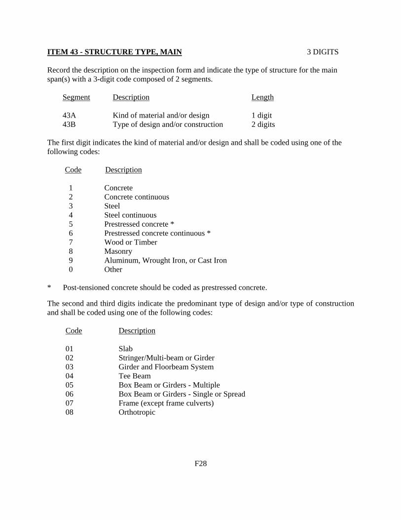
ITEM 43 - STRUCTURE TYPE, MAIN 3 DIGITS Record the description on the inspection form and indicate the type of structure for the main span(s) with a 3-digit code composed of 2 segments.
Segment Description Length 43A Kind of material and/or design 1 digit 43B Type of design and/or construction 2 digits
The first digit indicates the kind of material and/or design and shall be coded using one of the following codes: Code Description 1 Concrete 2 Concrete continuous 3 Steel 4 Steel continuous 5 Prestressed concrete * 6 Prestressed concrete continuous * 7 Wood or Timber 8 Masonry 9 Aluminum, Wrought Iron, or Cast Iron 0 Other * Post-tensioned concrete should be coded as prestressed concrete. The second and third digits indicate the predominant type of design and/or type of construction and shall be coded using one of the following codes:
Code Description 01 Slab 02 Stringer/Multi-beam or Girder 03 Girder and Floorbeam System 04 Tee Beam 05 Box Beam or Girders - Multiple 06 Box Beam or Girders - Single or Spread 07 Frame (except frame culverts) 08 Orthotropic
F28

ITEM 43 - STRUCTURE TYPE, MAIN (CONTINUED)
Code Description
09 Truss - Deck 10 Truss - Thru 11 Arch - Deck 12 Arch - Thru 13 Suspension 14 Stayed Girder 15 Movable - Lift 16 Movable - Bascule 17 Movable - Swing 18 Tunnel 19 Culvert (includes frame culverts) 20 * Mixed types 21 Segmental Box Girder 22 Channel Beam 00 Other
* Applicable only to approach spans - Item 44 Examples: Code Wood or Timber Through Truss 710 Masonry Culvert 819 Steel Suspension 313 Continuous Concrete Multiple Box Girders 205 Simple Span Concrete Slab 101 Tunnel in Rock 018 ITEM 44 - STRUCTURE TYPE, APPROACH SPANS 3 DIGITS Indicate with a 3-digit code composed of 2 segments, the type of structure for the approach spans to a major bridge or for the spans where the structural material is different. The codes are the same as for Item 43 preceding. However, code 000 if this item is not applicable. Use code 20 (Item 44B) when no one type of design and/or construction is predominate for the approach units. If the kind of material (Item 44A) is varied, code the most predominant.
F29

ITEM 44 - STRUCTURE TYPE, APPROACH SPANS (CONTINUED) Segment Description Length 44A Kind of material and/or design 1 digit 44B Type of design and/or construction 2 digits Examples: Code Simple prestressed concrete I-beam 502 Continuous concrete T-beam 204 Continuous steel deck truss 409 ITEM 45 - NUMBER OF SPANS IN MAIN UNIT 3 DIGITS Record the number and indicate with a 3-digit number the number of spans in the main or major unit. This item will include all spans of most bridges, the major unit only of a sizable structure, or a unit of material or design different from that of the approach spans. ITEM 46 - NUMBER OF APPROACH SPANS 4 DIGITS Record the number and indicate with a 4-digit number the number of spans in the approach spans to the major bridge, or the number of spans of material different from that of the major bridge. ITEM 47 - INVENTORY ROUTE, TOTAL HORIZONTAL CLEARANCE 3 DIGITS (XX.X feet) The total horizontal clearance for the inventory route identified in Item 5 should be measured and recorded. The clearance should be the available clearance measured between the restrictive features -- curbs, rails, walls, piers or other structural features limiting the roadway (surface and shoulders). The measurement should be recorded and coded as a 3-digit number truncated to the nearest tenth of a foot (with an assumed decimal point). When the restriction is 100 feet or greater, code 999.
F30
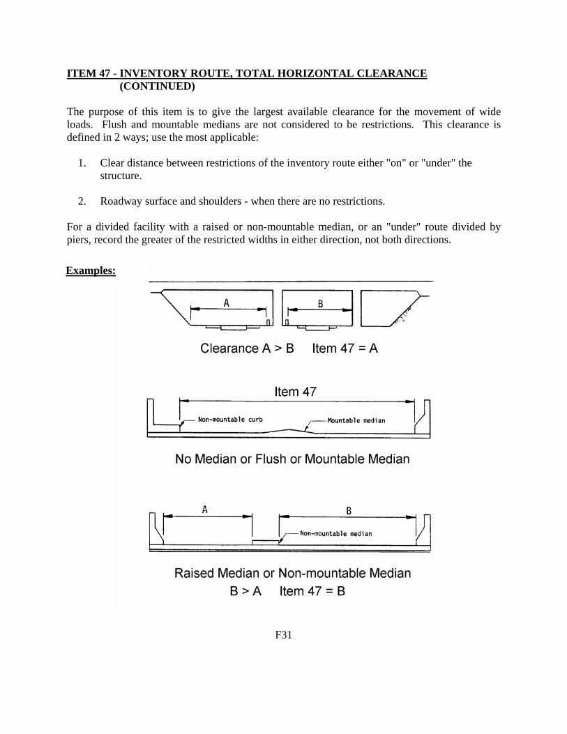
ITEM 47 - INVENTORY ROUTE, TOTAL HORIZONTAL CLEARANCE (CONTINUED) The purpose of this item is to give the largest available clearance for the movement of wide loads. Flush and mountable medians are not considered to be restrictions. This clearance is defined in 2 ways; use the most applicable: 1. Clear distance between restrictions of the inventory route either "on" or "under" the
structure. 2. Roadway surface and shoulders - when there are no restrictions. For a divided facility with a raised or non-mountable median, or an "under" route divided by piers, record the greater of the restricted widths in either direction, not both directions.
F31
Examples:

ITEM 48 - LENGTH OF MAXIMUM SPAN (XXXX feet) 4 DIGITS The length of the maximum span shall be recorded. It shall be noted whether the measurement is center to center of bearing points or clear open distance between piers, bents, or abutments. The measurement shall be along the centerline of the bridge. For this item, code a 4-digit number to represent the measurement to the nearest foot. Examples: Code Length of Maximum Span 50 feet 0050 117 feet 0117 1,050 feet 1050 ITEM 49 - STRUCTURE LENGTH (XXXXXX feet) 6 DIGITS Record and code a 6-digit number to represent the length of the structure to the nearest foot. This shall be the length of roadway which is supported on the bridge structure. The length should be measured back to back of backs walls of abutments or from paving notch to paving notch. Culvert lengths should be measured along the center line of roadway regardless of their depth below grade. Measurement should be made between inside faces of exterior walls. Tunnel length should be measured along the centerline of roadway. Be sure to code Item 5A = 2 for all tunnels. Examples: Structure Length Code 50 feet 000050 5,421 feet 005421 333 feet 000333 101,235 feet 101235
F32

ITEM 49 - STRUCTURE LENGTH (CONTINUED) Examples:
(1) Item 49 - Structure Length
F33

ITEM 49 - STRUCTURE LENGTH (CONTINUED)
Code (1) Item 49 - Structure Length = 18’ = 20.78’ 000021 cos 30o
F34
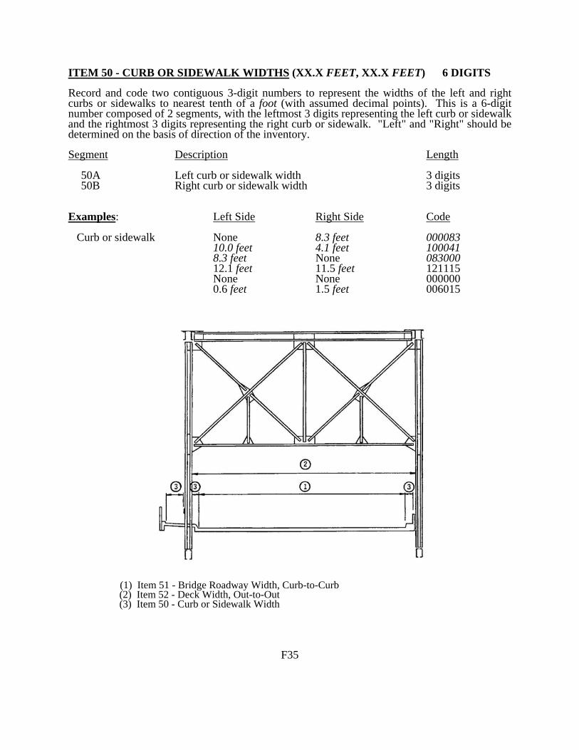
ITEM 50 - CURB OR SIDEWALK WIDTHS (XX.X FEET, XX.X FEET) 6 DIGITS Record and code two contiguous 3-digit numbers to represent the widths of the left and right curbs or sidewalks to nearest tenth of a foot (with assumed decimal points). This is a 6-digit number composed of 2 segments, with the leftmost 3 digits representing the left curb or sidewalk and the rightmost 3 digits representing the right curb or sidewalk. "Left" and "Right" should be determined on the basis of direction of the inventory. Segment Description Length 50A Left curb or sidewalk width 3 digits 50B Right curb or sidewalk width 3 digits Examples: Left Side Right Side Code Curb or sidewalk None 8.3 feet 000083 10.0 feet 4.1 feet 100041 8.3 feet None 083000 12.1 feet 11.5 feet 121115 None None 000000 0.6 feet 1.5 feet 006015
(1) Item 51 - Bridge Roadway Width, Curb-to-Curb (2) Item 52 - Deck Width, Out-to-Out (3) Item 50 - Curb or Sidewalk Width
F35

ITEM 50 - CURB OR SIDEWALK WIDTHS (CONTINUED) Examples:
(1) Item 51 - Bridge Roadway Width, Curb-to-Curb (2) Item 52 - Deck Width, Out-to-Out (3) Item 50 - Curb or Sidewalk Width
F36

ITEM 51 - BRIDGE ROADWAY WIDTH, CURB-TO-CURB (XXX.X feet) 4 DIGITS The information to be recorded is the most restrictive minimum distance between curbs or rails on the structure roadway. For structures with closed medians and usually for double decked structures, coded data will be the sum of the most restrictive minimum distances for all roadways carried by the structure*. The data recorded for this item must be compatible with other related route and bridge data (i.e., Items 28, 29, 32, etc.). The measurement should be exclusive of flared areas for ramps. A 4-digit number should be used to represent the distance to the nearest tenth of a foot (with an assumed decimal point). See examples on pages F35 and F36. Where traffic runs directly on the top slab (or wearing surface) of a culvert- type structure, e.g. an R/C box without fill, code the actual roadway width (curb-to-curb or rail-to-rail). This will also apply where the fill is minimal and headwalls or parapets affect the flow of traffic. Where the roadway is on fill carried across a structure and the headwalls or parapets do not affect the flow of traffic, code 0000. This is considered proper inasmuch as a filled section simply maintains the roadway cross-section. However, for sidehill viaduct structures code the actual full curb-to-curb roadway width. See figure in the Commentary Appendix D. * Raised or non-mountable medians, open medians, and barrier widths are to be excluded
from the summation along with barrier-protected bicycle and equestrian lanes. Examples: Code Bridge Roadway Width 36.00 feet wide 0360 66.37 feet wide 0664 110.13 feet wide 1101 The last example above would be the coded value for the deck section shown below.
F37

ITEM 52 - DECK WIDTH, OUT-TO-OUT (XXX.X FEET) 4 DIGITS Record and code a 4-digit number to show the out-to-out width to the nearest tenth of a foot (with an assumed decimal point). If the structure is a through structure, the number to be coded will represent the lateral clearance between superstructure members. The measurement should be exclusive of flared areas for ramps. See examples on pages F35 and F36. Where traffic runs directly on the top slab (or wearing surface) of the culvert (e.g., an R/C box without fill) code the actual width (out-to-out). This will also apply where the fill is minimal and the culvert headwalls affect the flow of traffic. However, for sidehill viaduct structures code the actual out-to-out structure width. See figure in the Commentary Appendix D. Where the roadway is on a fill carried across a pipe or box culvert and the culvert headwalls do not affect the flow of traffic, code 0000. This is considered proper inasmuch as a filled section over a culvert simply maintains the roadway cross-section. ITEM 53 - MINIMUM VERTICAL CLEARANCE OVER BRIDGE 4 DIGITS ROADWAY (XX.XX feet) The information to be recorded for this item is the actual minimum vertical clearance over the bridge roadway, including shoulders, to any superstructure restriction, rounded down to the nearest hundredth of a foot. For double decked structures code the minimum, regardless whether it is pertaining to the top or bottom deck. When no superstructure restriction exists above the bridge roadway, code 9999. A 4-digit number should be coded to represent the clearance in feet. Examples: Code Minimum Vertical Clearance No restriction 9999 17’-3” 1725 75’-11” 7591 115’-6” 9999 ITEM 54 - MINIMUM VERTICAL UNDERCLEARANCE 5 DIGITS (X code, XX.XX feet) Using a 1-digit code and a 4-digit number, record and code the minimum vertical clearance from the roadway (travel lanes only) or railroad track beneath the structure to the underside of the superstructure. (When both a railroad and highway are under the structure, code the most critical dimension.) Segment Description Length 54A Reference feature 1 digit 54B Minimum Vertical Underclearance 4 digits
F38

ITEM 54 - MINIMUM VERTICAL UNDERCLEARANCE (CONTINUED) Using one of the codes below, code in the first position, the reference feature from which the clearance measurement is taken: Code Description H Highway beneath structure R Railroad beneath structure N Feature not a highway or railroad In the next 4 positions, code a 4-digit number to represent the minimum vertical clearance from that feature to the structure. When a restriction is 100 feet or greater, code 9999. If the feature is not a highway or railroad, code the minimum vertical clearance 0000. Examples: Code River beneath structure N0000
Railroad 31’-3” beneath structure R3125
Highway 34’-4” beneath structure H3433 F39
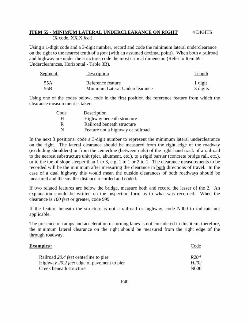
ITEM 55 - MINIMUM LATERAL UNDERCLEARANCE ON RIGHT 4 DIGITS (X code, XX.X feet) Using a 1-digit code and a 3-digit number, record and code the minimum lateral underclearance on the right to the nearest tenth of a foot (with an assumed decimal point). When both a railroad and highway are under the structure, code the most critical dimension (Refer to Item 69 - Underclearances, Horizontal - Table 3B). Segment Description Length 55A Reference feature 1 digit 55B Minimum Lateral Underclearance 3 digits Using one of the codes below, code in the first position the reference feature from which the clearance measurement is taken: Code Description H Highway beneath structure R Railroad beneath structure N Feature not a highway or railroad In the next 3 positions, code a 3-digit number to represent the minimum lateral underclearance on the right. The lateral clearance should be measured from the right edge of the roadway (excluding shoulders) or from the centerline (between rails) of the right-hand track of a railroad to the nearest substructure unit (pier, abutment, etc.), to a rigid barrier (concrete bridge rail, etc.), or to the toe of slope steeper than 1 to 3, e.g. 1 to 1 or 2 to 1. The clearance measurements to be recorded will be the minimum after measuring the clearance in both directions of travel. In the case of a dual highway this would mean the outside clearances of both roadways should be measured and the smaller distance recorded and coded. If two related features are below the bridge, measure both and record the lesser of the 2. An explanation should be written on the inspection form as to what was recorded. When the clearance is 100 feet or greater, code 999. If the feature beneath the structure is not a railroad or highway, code N000 to indicate not applicable. The presence of ramps and acceleration or turning lanes is not considered in this item; therefore, the minimum lateral clearance on the right should be measured from the right edge of the through roadway. Examples: Code Railroad 20.4 feet centerline to pier R204 Highway 20.2 feet edge of pavement to pier H202 Creek beneath structure N000 F40
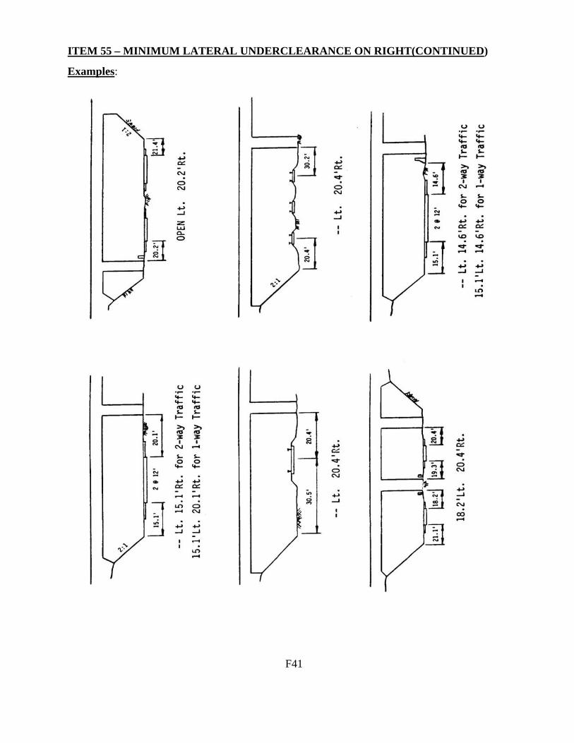
ITEM 55 – MINIMUM LATERAL UNDERCLEARANCE ON RIGHT(CONTINUED) Examples:
F41

ITEM 56 - MINIMUM LATERAL UNDERCLEARANCE ON LEFT 3 DIGITS (XX.X feet) (code only for divided highways, 1-way streets, and ramps; not applicable to railroads) Using a 3-digit number, record and code the minimum lateral under- clearance on the left (median side for divided highways) to the nearest tenth of a foot (with an assumed decimal point). The lateral clearance should be measured from the left edge of the roadway (excluding shoulders) to the nearest substructure unit, to a rigid barrier, or to the toe of slope steeper than 1 to 3. Refer to examples on page F41 under Item 55 - Minimum Lateral Underclearance on Right. In the case of a dual highway, the median side clearances of both roadways should be measured and the smaller distance recorded and coded. If there is no obstruction in the median area, a notation of "open" should be recorded and 999 should be coded. For clearances greater than 100 feet, code 998. Code 000 to indicate not applicable.
ITEM 57 (Reserved) ITEMS 58 THROUGH 62 - INDICATE THE CONDITION RATINGS In order to promote uniformity between bridge inspectors, these guidelines will be used to rate and code Items 58, 59, 60, 61, and 62. The use of the AASHTO Guide for Commonly Recognized (CoRe) Structural Elements is an acceptable alternative to using these rating guidelines for Items 58, 59, 60, and 62, provided the FHWA translator computer program is used to convert the inspection data to NBI condition ratings for NBI data submittal. Condition ratings are used to describe the existing, in-place bridge as compared to the as-built condition. Evaluation is for the materials related, physical condition of the deck, superstructure, and substructure components of a bridge. The condition evaluation of channels and channel protection and culverts is also included. Condition codes are properly used when they provide an overall characterization of the general condition of the entire component being rated. Conversely, they are improperly used if they attempt to describe localized or nominally occurring instances of deterioration or disrepair. Correct assignment of a condition code must, therefore, consider both the severity of the deterioration or disrepair and the extent to which it is widespread throughout the component being rated. The load-carrying capacity will not be used in evaluating condition items. The fact that a bridge was designed for less than current legal loads and may be posted shall have no influence upon condition ratings. Portions of bridges that are being supported or strengthened by temporary members will be rated based on their actual condition; that is, the temporary members are not considered in the rating of the item. (See Item 103 - Temporary Structure Designation for the definition of a temporary bridge.) Completed bridges not yet opened to traffic, if rated, shall be coded as if open to traffic.
F42

CONDITION RATINGS (CONTINUED) The following general condition ratings shall be used as a guide in evaluating Items 58, 59, and 60: Code Description N NOT APPLICABLE 9 EXCELLENT CONDITION 8 VERY GOOD CONDITION - no problems noted. 7 GOOD CONDITION - some minor problems. 6 SATISFACTORY CONDITION - structural elements show some minor deterioration. 5 FAIR CONDITION - all primary structural elements are sound but may have minor
section loss, cracking, spalling or scour. 4 POOR CONDITION - advanced section loss, deterioration, spalling or scour. 3 SERIOUS CONDITION - loss of section, deterioration, spalling or scour have
seriously affected primary structural components. Local failures are possible. Fatigue cracks in steel or shear cracks in concrete may be present.
2 CRITICAL CONDITION - advanced deterioration of primary structural elements. Fatigue cracks in steel or shear cracks in concrete may be present or scour may have removed substructure support. Unless closely monitored it may be necessary to close the bridge until corrective action is taken.
1 "IMMINENT" FAILURE CONDITION - major deterioration or section loss present in critical structural components or obvious vertical or horizontal movement affecting structure stability. Bridge is closed to traffic but corrective action may put back in light service.
0 FAILED CONDITION - out of service - beyond corrective action. ITEM 58 - DECK 1 DIGIT This item describes the overall condition rating of the deck. Rate and code the condition in accordance with the above general condition ratings. Code N for culverts and other structures without decks e.g., filled arch bridge. Concrete decks should be inspected for cracking, scaling, spalling, leaching, chloride contamination, potholing, delamination, and full or partial depth failures. Steel grid decks should be inspected for broken welds, broken grids, section loss, and growth of filled grids from corrosion. Timber decks should be inspected for splitting, crushing, fastener failure, and deterioration from rot. The condition of the wearing surface/protective system, joints, expansion devices, curbs, sidewalks, parapets, fascias, bridge rail, and scuppers shall not be considered in the overall deck evaluation. However, their condition should be noted on the inspection form. Decks integral with the superstructure will be rated as a deck only and not how they may influence the superstructure rating (for example, rigid frame, slab, deck girder or T-beam, voided slab, box girder, etc.). Similarly, the superstructure of an integral deck-type bridge will not influence the deck rating.
F43
ITEM 59 - SUPERSTRUCTURE 1 DIGIT This item describes the physical condition of all structural members. Rate and code the condition in accordance with the previously described general condition ratings. Code N for all culverts. The structural members should be inspected for signs of distress which may include cracking, deterioration, section loss, and malfunction and misalignment of bearings. The condition of bearings, joints, paint system, etc. shall not be included in this rating, except in extreme situations, but should be noted on the inspection form. On bridges where the deck is integral with the superstructure, the superstructure condition rating may be affected by the deck condition. The resultant superstructure condition rating may be lower than the deck condition rating where the girders have deteriorated or been damaged. Fracture critical components should receive careful attention because failure could lead to collapse of a span or the bridge. ITEM 60 - SUBSTRUCTURE 1 DIGIT This item describes the physical condition of piers, abutments, piles, fenders, footings, or other components. Rate and code the condition in accordance with the previously described general condition ratings. Code N for all culverts. All substructure elements should be inspected for visible signs of distress including evidence of cracking, section loss, settlement, misalignment, scour, collision damage, and corrosion. The rating given to Item 60 should be consistent with the one given to Item 113 whenever a rating factor of 2 or below is determined for Item 113-Scour Critical Bridges. The substructure condition rating shall be made independent of the deck and superstructure. Integral-abutment wingwalls to the first construction or expansion joint shall be included in the evaluation. For non-integral superstructure and substructure units, the substructure shall be considered as the portion below the bearings. For structures where the substructure and superstructure are integral, the substructure shall be considered as the portion below the superstructure.
F44
ITEM 61 - CHANNEL AND CHANNEL PROTECTION 1 DIGIT This item describes the physical conditions associated with the flow of water through the bridge such as stream stability and the condition of the channel, riprap, slope protection, or stream control devices including spur dikes. The inspector should be particularly concerned with visible signs of excessive water velocity which may affect undermining of slope protection, erosion of banks, and realignment of the stream which may result in immediate or potential problems. Accumulation of drift and debris on the superstructure and substructure should be noted on the inspection form but not included in the condition rating. Rate and code the condition in accordance with the previously described general condition ratings and the following descriptive codes: Code Description N Not applicable. Use when bridge is not over a waterway (channel). 9 There are no noticeable or noteworthy deficiencies which affect the condition of the
channel. 8 Banks are protected or well vegetated. River control devices such as spur dikes and
embankment protection are not required or are in a stable condition. 7 Bank protection is in need of minor repairs. River control devices and embankment
protection have a little minor damage. Banks and/or channel have minor amounts of drift.
6 Bank is beginning to slump. River control devices and embankment protection have
widespread minor damage. There is minor stream bed movement evident. Debris is restricting the channel slightly.
5 Bank protection is being eroded. River control devices and/or embankment have
major damage. Trees and brush restrict the channel. 4 Bank and embankment protection is severely undermined. River control devices
have severe damage. Large deposits of debris are in the channel. 3 Bank protection has failed. River control devices have been destroyed. Stream bed
aggradation, degradation or lateral movement has changed the channel to now threaten the bridge and/or approach roadway.
2 The channel has changed to the extent the bridge is near a state of collapse. 1 Bridge closed because of channel failure. Corrective action may put back in light
service. 0 Bridge closed because of channel failure. Replacement necessary.
F45
ITEM 62 - CULVERTS 1 DIGIT This item evaluates the alignment, settlement, joints, structural condition, scour, and other items associated with culverts. The rating code is intended to be an overall condition evaluation of the culvert. Integral wingwalls to the first construction or expansion joint shall be included in the evaluation. For a detailed discussion regarding the inspection and rating of culverts, consult Report No. FHWA-IP-86-2, Culvert Inspection Manual, July 1986. Item 58 - Deck, Item 59 - Superstructure, and Item 60 - Substructure shall be coded N for all culverts. Rate and code the condition in accordance with the previously described general condition ratings and the following descriptive codes: Code Description N Not applicable. Use if structure is not a culvert. 9 No deficiencies. 8 No noticeable or noteworthy deficiencies which affect the condition of the culvert.
Insignificant scrape marks caused by drift. 7 Shrinkage cracks, light scaling, and insignificant spalling which does not expose
reinforcing steel. Insignificant damage caused by drift with no misalignment and not requiring corrective action. Some minor scouring has occurred near curtain walls, wingwalls, or pipes. Metal culverts have a smooth symmetrical curvature with superficial corrosion and no pitting.
6 Deterioration or initial disintegration, minor chloride contamination, cracking with some
leaching, or spalls on concrete or masonry walls and slabs. Local minor scouring at curtain walls, wingwalls, or pipes. Metal culverts have a smooth curvature, non-symmetrical shape, significant corrosion or moderate pitting.
5 Moderate to major deterioration or disintegration, extensive cracking and leaching, or
spalls on concrete or masonry walls and slabs. Minor settlement or misalignment. Noticeable scouring or erosion at curtain walls, wingwalls, or pipes. Metal culverts have significant distortion and deflection in one section, significant corrosion or deep pitting.
4 Large spalls, heavy scaling, wide cracks, considerable efflorescence, or opened
construction joint permitting loss of backfill. Considerable settlement or misalignment. Considerable scouring or erosion at curtain walls, wingwalls or pipes. Metal culverts have significant distortion and deflection throughout, extensive corrosion or deep pitting.
(codes continued on the next page)
F46

ITEM 62 - CULVERTS (CONTINUED) Code Description 3 Any condition described in Code 4 but which is excessive in scope. Severe movement
or differential settlement of the segments, or loss of fill. Holes may exist in walls or slabs. Integral wingwalls nearly severed from culvert. Severe scour or erosion at curtain walls, wingwalls or pipes. Metal culverts have extreme distortion and deflection in one section, extensive corrosion, or deep pitting with scattered perforations.
2 Integral wingwalls collapsed, severe settlement of roadway due to loss of fill. Section
of culvert may have failed and can no longer support embankment. Complete undermining at curtain walls and pipes. Corrective action required to maintain traffic. Metal culverts have extreme distortion and deflection throughout with extensive perforations due to corrosion.
1 Bridge closed. Corrective action may put back in light service. 0 Bridge closed. Replacement necessary. ITEM 63 - METHOD USED TO DETERMINE OPERATING RATING 1 DIGIT Use one of the codes below to indicate which load rating method was used to determine the Operating Rating coded in Item 64 for this structure. Code Description 1 Load Factor (LF) 2 Allowable Stress (AS) 3 Load and Resistance Factor (LRFR) 4 Load Testing 5 No rating analysis performed ITEM 64 - OPERATING RATING (XX.X english tons) 3 DIGITS This capacity rating, referred to as the operating rating, will result in the absolute maximum permissible load level to which the structure may be subjected for the vehicle type used in the rating. Code the operating rating as a 3-digit number to represent the total mass in english tons of the entire vehicle measured to the nearest tenth of a english ton (with an assumed decimal point). It should be emphasized that only HS loading shall be used to determine the operating rating. The total mass in tons of the entire vehicle should be coded; that is, HS18 which has a mass of 32.4 english tons shall be coded '324', and likewise, a HS13.5 shall be coded '135'.
F47

ITEM 64 - OPERATING RATING (CONTINUED) The AASHTO Manual for Condition Evaluation of Bridges provides a choice of load rating methods, such as the new load and resistance factor (LRFR) rating method, in addition to the traditional allowable stress (AS) and load factor (LF) methods. Of the three rating methods, the LF method is the most suitable for use as a national standard, therefore the FHWA has chosen the LF method as the standard for computing inventory and operating ratings reported to the NBI. The highway agencies may, however, elect to use LF, AS or LRFD to establish load limits for purposes of load posting. If the bridge will not carry a minimum of 3 english tons of live load, the operating rating shall be coded '000'; and consistent with the direction of the AASHTO Manual, it shall be closed. The use or presence of a temporary bridge requires special consideration in coding. In such cases, since there is no permanent bridge, Items 64 and 66 should be coded as 000 even though the temporary structure is rated for as much as full legal load. A bridge shored up or repaired on a temporary basis is considered a temporary bridge and the inventory and operating rating shall be coded as if the temporary shoring were not in place. See Item 103 - Temporary Structure Designation for definition of a temporary bridge. Code 999 for a structure under sufficient fill such that, according to AASHTO design, the live load is insignificant in the structure load capacity. Examples: Code HS27 486 Temporary bridge 000 Shored-up bridge 030* Structure under fill (not affected by live load) 999 * load capacity without shoring.
F48

ITEM 65 - METHOD USED TO DETERMINE INVENTORY RATING 1 DIGIT Use one of the codes below to indicate which load rating method was used to determine the Inventory Rating coded in Item 66 for this structure. Code Description 1 Load Factor (LF) 2 Allowable Stress (AS) 3 Load and Resistance Factor (LRFR) 4 Load Testing 5 No rating analysis performed ITEM 66 - INVENTORY RATING (XX.X english tons) 3 DIGITS This capacity rating, referred to as the inventory rating, will result in a load level which can safely utilize an existing structure for an indefinite period of time. Only the HS loading shall be used to determine the inventory rating. Code the Inventory Rating as a 3-digit number to represent the total mass in english tons of the entire vehicle measured to the nearest tenth of a english ton (with an assumed decimal point). The statements in Item 64 - Operating Rating apply to this item also. Code 999 for a structure under sufficient fill such that, according to AASHTO design, the live load is insignificant in the structure load capacity. ITEMS 67, 68, 69, 71, AND 72 - INDICATE THE APPRAISAL RATINGS The items in the Appraisal Section are used to evaluate a bridge in relation to the level of service which it provides on the highway system of which it is a part. The structure will be compared to a new one which is built to current standards for that particular type of road as further defined in this section except for Item 72 - Approach Roadway Alignment. See Item 72 for special criteria for rating that item. Items 67, 68, 69, 71, and 72 will be coded with a 1-digit code that indicates the appraisal rating for the item. The ratings and codes are as follows: Code Description N Not applicable 9 Superior to present desirable criteria 8 Equal to present desirable criteria 7 Better than present minimum criteria 6 Equal to present minimum criteria 5 Somewhat better than minimum adequacy to tolerate being left in place as is 4 Meets minimum tolerable limits to be left in place as is 3 Basically intolerable requiring high priority of corrective action 2 Basically intolerable requiring high priority of replacement 1 This value of rating code not used 0 Bridge closed
F49

ITEMS 67, 68, 69, 71, AND 72 - INDICATE THE APPRAISAL RATINGS The FHWA Edit/Update computer program calculates values for Items 67, 68 and 69 according to the tables provided in this manual. These tables and the table for Item 71 shall be used by all evaluators to rate these items. They have been developed to closely match the descriptions for the appraisal evaluation codes of 0 to 9. The tables shall be used in all instances to evaluate the item based on the designated data in the inventory, even if a table value does not appear to match the descriptive codes. For unusual cases where the site data does not exactly agree with the table criteria, use the most appropriate table to evaluate the item. The code of N is not valid for use with Items 67 and 72. Completed bridges not yet opened to traffic, if rated, shall be appraised as if open to traffic. Design values, for example ADT, shall be used for the evaluation. The data provided will include a code of G for Item 41 - Structure Open, Posted, or Closed to Traffic. ITEM 67 - STRUCTURAL EVALUATION 1 DIGIT This item is calculated by the Edit/Update Program based on Table 1, and need not be coded by the bridge inspector. The following specifications are used by the Edit/Update Program: ! For structures other than culverts, the lowest of the codes obtained from Item 59 -
Superstructure, Item 60 - Substructure, or Table 1 is used. ! For culverts, the lowest of the codes obtained from Item 62 - Culverts, or Table 1 is used. ! If Item 59, Item 60 or Item 62 is coded 1, then Item 67 is equal to zero (0), regardless of
whether the structure is actually closed. However, if the structure is closed, it does not mean that this value is zero (0) unless the overall condition and appraisal ratings indicate that a code of 0 is appropriate.
Table 1 Notes: 1. Use the lower rating code for values between those listed in the table. 2. Inventory Ratings are shown in english tons with decimal point. 3. To use Table 1, the Inventory Rating must be the coded HS rating or its equivalent. If the
comparable HS equivalent is not calculated for the controlling rating, using a factor to determine the HS equivalent is acceptable even though converting other rating loads to an HS equivalent is not a constant.
4. All bridges with Item 26 - Functional Class coded Interstate, Freeway or Expressway shall
be evaluated using the ADT column of >5000 regardless of the actual ADT on the bridge.
F50

ITEM 67 - STRUCTURAL EVALUATION (CONTINUED) Table 1. Rating by Comparison of ADT - Item 29 and Inventory Rating - Item 66
Inventory Rating
Average Daily Traffic (ADT)
Structural Evaluation Rating Code
0-500
501-5000
>5000
9
>36 (HS20)*
>36
(HS20)
>36
(HS20)
8
=36 (HS20)
=36
(HS20)
=36
(HS20)
7
>31 (HS17)
>31
(HS17)
>31
(HS17)
6
>23 (HS13)
>25
(HS14)
>27
(HS15)
5
>18 (HS10)
>20
(HS11)
>22
(HS12)
4
>12
(HS7)
>14
(HS8)
>18
(HS10)
3
Inventory rating less than value in rating code of 4 and requiring corrective action.
2
Inventory rating less than value in rating
code of 4 and requiring replacement.
0
Bridge closed due to structural condition.
*HS Designation (typical)
F51

ITEM 68 - DECK GEOMETRY 1 DIGIT This item is calculated by the Edit/Update Program and need not be coded by the bridge inspector. The overall rating for deck geometry includes two evaluations: (a) the curb-to-curb or face-to-face of rail bridge width using Table 2A, B, C or D and (b) the minimum vertical clearance over the bridge roadway using Table 2E. The lower of the codes obtained from these tables is used by the Edit/Update Program. When an individual table lists several deck geometry rating codes for the same roadway width under a specific ADT, the lower code is used. (For example, Table 2A lists deck geometry rating codes of 6, 7 and 8 for a 44 foot roadway width and an ADT of >5000. Use the code of 6.) For values between those listed in the tables, the lower code is used. The curb-to-curb or face-to-face of rail dimension shall be taken from Item 51 - Bridge Roadway Width, Curb-to-curb. Item 53 - Minimum Vertical Clearance Over Bridge Roadway is used to evaluate the vertical clearance. For culverts which have Item 51 - Bridge Roadway Width coded 0000, the Deck Geometry code will be equal to N. The values provided in the tables are for rating purposes only. Current design standards must be used for structure design or rehabilitation.
F52

ITEM 68 - DECK GEOMETRY (CONT'D) Table 2A & 2B. Rating by Comparison of ADT - Item 29 and
Bridge Roadway Width, Curb-to-Curb - Item 51
TABLE 2A
TABLE 2B
Bridge Roadway Width 2 Lanes; 2 Way Traffic
Bridge Roadway Width 1 Lane; 2-Way Traffic
ADT (Both Directions)
ADT (Both Directions)
Deck Geometry Rating Code
0-100
101- 400
401- 1000
1001- 2000
2001- 5000
>5000
0-100
>100
9
>32
>36
>40
>44
>44
>44
-
-
8
=32
=36
=40
=44
=44
=44
<15.91’
-
7
>28
>32
>36
>40
=44
=44
>15
-
6
>24
>28
>30
>34
>40
=44
>14
-
5
>20
>24
>26
>28
>34
>38
>13
-
4
>18
>20
>22
>24
>28
>32 (28)*
>12
-
3
>16
>18
>20
>22
>26
>30 (26)*
>11
<15.91’
2
Any width less than required for a rating code of 3 and structure is open.
0
Bridge Closed
* Use value in parentheses for bridges longer than 200 feet. Notes: 1. Use the lower rating code for values between those listed in the table. 2. Dimensions are in feet. 3. For 1 lane of one-way traffic Table 2A is used. 4. For 3 or more undivided lanes of 2-way traffic, use Table 2C, Other Multilane Divided Facilities. 5. Do not use Table 2B for code 9 and for codes 8 through 4 inclusive when the ADT >100. Single
lane bridges less than 16 feet wide carrying 2-way traffic are always appraised at 3 or below if they carry more than an ADT of 100.
6. One-lane bridges 16 feet and greater in roadway width, which are not ramps, are evaluated as a 2-lane bridge using Table 2A.
F53

ITEM 68 - DECK GEOMETRY (CONTINUED)
Table 2C & 2D. Rating by Comparison of Number of Lanes - Item 28 and Bridge Roadway Width, Curb-to-Curb - Item 51
TABLE 2C
TABLE 2D
Bridge Roadway Width 2 or More Lanes
Bridge Roadway Width
1-Way Traffic Interstate and Other Divided Freeways
Other Multilane Divided Facilities
Ramps Only
(Item 5C = 7)
Deck Geometry Rating Code
2 Lanes 1-way
3 or more Lanes
2 Lanes 1-way
3 or more Lanes
1 Lane
2 or more Lanes
9
>42
>12N+24
>42
>12N+18
>26
>12N+12
8
=42
=12N+24
=42
=12N+18
=26
=12N+12
7
>40
>12N+20
>38
>12N+15
>24
>12N+10
6
>38
>12N+16
>36
>12N+12
>22
>12N+8
5
>36
>12N+14
>33
>11N+10
>20
>12N+6
4 4
>34
>(29)*
>11N+12 >(11N+7)*
>30 >30
>11N+6 >11N+6
>18 >18
>12N+4 >12N+4
3 3
>33
>(28)*
>11N+11 >(11N+6)*
>27 >27
>11N+5 >11N+5
>16 >16
>12N+2 >12N+2
2
Any width less than required for a rating code of 3 and structure is open.
0
Bridge Closed
* Use value in parentheses for bridges longer than 200 feet. N = Total number of lanes of traffic on the structure. Notes 1. Use the lower rating code for values between those listed in the tables. 2. Dimensions are in feet. 3. Use Table 2C, Other Multilane Divided Facilities, for 3 or more undivided lanes of 2-way
traffic.
F54

ITEM 68 - DECK GEOMETRY (CONTINUED) Table 2E. Rating by Comparison of Minimum Vertical Clearance over Bridge Roadway - Item 53 and Functional Classification - Item 26
Minimum Vertical Clearance
Functional Class
Deck Geometry Rating Code
Interstate and Other Freeway
Other Principal and Minor Arterial
Major and Minor Collectors and Locals
9
>17.00
>16.50’
>16.50’
8
=17.00’
=16.50’
=16.50’
7
>16.75’
>15.50’
>15.50’
6
>16.50’
>14.50’
>14.50’
5
>15.75’
>14.25’
>14.25’
4
>15.00’
>14.00’
>14.00’
3
Vertical clearance less than value in rating code of 4 and requiring corrective action.
2
Vertical clearance less than value in rating code of 4 and requiring replacement.
0
Bridge Closed.
Notes 1. Use the lower rating code for values between those listed in the table. 2. Dimensions are in feet.
F55

ITEM 69 - UNDERCLEARANCES, VERTICAL AND HORIZONTAL 1 DIGIT This item is calculated by the Edit/Update Program and need not be coded by the bridge inspector. Vertical and horizontal underclearances are measured from the through roadway to the superstructure or substructure units, respectively. Code "N" is used unless the bridge is over a highway or railroad. The vertical underclearance is evaluated using Table 3A. The horizontal underclearance is evaluated using Table 3B. The lower of the codes obtained from Table 3A and Table 3B is used by the Edit/Update Program. Bridges seldom are closed due to deficient underclearances, however, these bridges may be good candidates for rehabilitation or replacement. Item 54 - Minimum Vertical Underclearance, Item 55 - Minimum Lateral Underclearance on Right, and Item 56 - Minimum Lateral Underclearance on Left are used to evaluate this item. The functional classification used in the table is for the underpassing route. Therefore, the functional classification is obtained from the record for the route "under" the bridge (see Item 5 - Inventory Route). If the underpassing route is not on a Federal-aid system, is not a defense route, or is not otherwise important, an "under" record may not be available. If no "under" record exits, it is assumed that the route under the bridge is a major or minor collector or a local road for the purpose of using Tables 3A and 3B. NOTE: New Jersey always requires an “under” record to be coded for highways.
F56
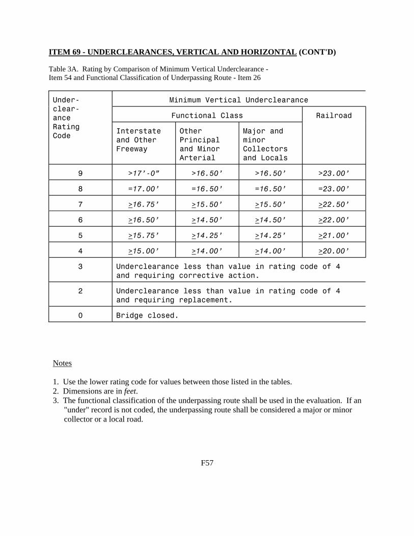
ITEM 69 - UNDERCLEARANCES, VERTICAL AND HORIZONTAL (CONT'D) Table 3A. Rating by Comparison of Minimum Vertical Underclearance - Item 54 and Functional Classification of Underpassing Route - Item 26
Minimum Vertical Underclearance
Functional Class
Under- clear- ance Rating Code
Interstate and Other Freeway
Other Principal and Minor Arterial
Major and minor Collectors and Locals
Railroad
9
>17’-0”
>16.50’
>16.50’
>23.00’
8
=17.00’
=16.50’
=16.50’
=23.00’
7
>16.75’
>15.50’
>15.50’
>22.50’
6
>16.50’
>14.50’
>14.50’
>22.00’
5
>15.75’
>14.25’
>14.25’
>21.00’
4
>15.00’
>14.00’
>14.00’
>20.00’
3
Underclearance less than value in rating code of 4 and requiring corrective action.
2
Underclearance less than value in rating code of 4 and requiring replacement.
0
Bridge closed.
Notes 1. Use the lower rating code for values between those listed in the tables. 2. Dimensions are in feet. 3. The functional classification of the underpassing route shall be used in the evaluation. If an
"under" record is not coded, the underpassing route shall be considered a major or minor collector or a local road.
F57

ITEM 69 - UNDERCLEARANCES, VERTICAL AND HORIZONTAL (CONTINUED) Table 3B. Rating by Comparison of Minimum Lateral Underclearances Right & Left - Items 55 & 56 and Functional Classification of Underpassing Route - Item 26
Minimum Lateral Underclearance
Functional Class
1-Way Traffic
2-Way Traffic
Principal Arterial- Interstate, Freeways or Expressways
Main Line
Ramp
Under- clear- ance Rating Code
Left
Right
Left
Right
Other Principal and Minor Arterial
Major and Minor Collectors and Locals
Railroad
9
>30
>30
>4
>10
>30
>12
>20
8
30
30
4
10
30
12
20
7
18
21
3
9
21
11
17
6
6
12
2
8
12
10
14
5
5
11
2
6
10
8
11
4
4
10
2
4
6
4
8
3
Underclearance less than value in rating code of 4 and requiring corrective action.
2
Underclearance less than value in rating code of 4 and requiring replacement.
0
Bridge closed.
Notes: 1. Use the lower rating code for values between those listed in the tables. 2. Dimensions are in feet. 3. When acceleration or deceleration lanes or ramps are provided under 2-way traffic, use the
value from the right ramp column to determine code. 4. The functional classification of the underpassing route shall be used in the evaluation. If an
"under" record is not coded, the underpassing route shall be considered a major or minor collector or a local road.
F58

ITEM 70 - BRIDGE POSTING 1 DIGIT The National Bridge Inspection Standards require the posting of load limits only if the maximum legal load configurations in the State exceeds the load permitted under the operating rating. If the load capacity at the operating rating is such that posting is required, this item shall be coded 4 or less. If no posting is required at the operating rating, this item shall be coded 5. This item evaluates the load capacity of a bridge in comparison to the State legal load. It differs from Item 67 - Structural Evaluation in that Item 67 uses Item 66 - Inventory Rating, while the bridge posting requirement is based on Item 64 - Operating Rating. Although posting a bridge for load-carrying capacity is required only when the maximum legal load exceeds the operating rating, highway agencies may choose to post at a lower level. This posting practice may appear to produce conflicting coding when Item 41 - Structure Open, Posted or Closed to Traffic is coded to show the bridge as actually posted at the site and Item 70 - Bridge Posting is coded as bridge posting is not required. Since different criteria are used for coding these 2 items, this coding is acceptable and correct when the highway agency elects to post at less than the operating rating. Item 70 shall be coded 4 or less only if the legal load of the State exceeds that permitted under the operating rating. The use or presence of a temporary bridge affects the coding. The actual operating rating of the temporary bridge should be used to determine this item. However the highway agency may choose to post at a lower level. This also applies to bridges shored up or repaired on a temporary basis.
Code Description
4 or less Posting required 5 No posting required
The degree that the operating rating is less than the maximum legal load level may be used to differentiate between codes. As a guide and for coding purposes only, the following values may be used to code this item:
Code Relationship of Operating Rating to Maximum Legal Load
5 Equal to or above legal loads 4 0.1 - 9.9% below 3 10.0 - 19.9% below 2 20.0 - 29.9% below 1 30.0 - 39.9% below 0 > 39.9% below
NOTE: Refer to page SA-3 of the Guide for “Relationship” calculation example.
F59

ITEM 71 - WATERWAY ADEQUACY 1 DIGIT This item appraises the waterway opening with respect to passage of flow through the bridge. The following codes shall be used in evaluating waterway adequacy (interpolate where appropriate). Site conditions may warrant somewhat higher or lower ratings than indicated by the table (e.g., flooding of an urban area due to a restricted bridge opening). Where overtopping frequency information is available, the descriptions given in the table for chance of overtopping mean the following: Remote - greater than 100 years Slight - 11 to 100 years Occasional - 3 to 10 years Frequent - less than 3 years Adjectives describing traffic delays mean the following: Insignificant - Minor inconvenience. Highway passable in a matter of hours. Significant - Traffic delays of up to several days. Severe - Long term delays to traffic with resulting hardship. Functional Classification Principal Arterials - Interstates, Freeways, or Expressways
Other Principal and Minor Arterials and Major Collectors
Minor Collectors Locals
Description
CODE N N N Bridge not over a waterway.
9 9 9 Bridge deck and roadway approaches above
flood water elevations (high water). Chance of overtopping is remote.
8 8 8 Bridge deck above roadway approaches. Slightchance of overtopping roadway approaches.
6 6 7 Slight chance of overtopping bridge deck and roadway approaches.
4 5 6 Bridge deck above roadway approaches. Occasional overtopping of roadway approaches with insignificant traffic delays.
(codes continued on the next page)
F60
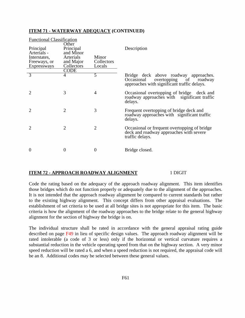
ITEM 71 - WATERWAY ADEQUACY (CONTINUED) Functional Classification Principal Arterials - Interstates, Freeways, or Expressways
Other Principal and Minor Arterials and Major Collectors
Minor Collectors Locals
Description
CODE 3 4 5 Bridge deck above roadway approaches.
Occasional overtopping of roadway approaches with significant traffic delays.
2 3 4 Occasional overtopping of bridge deck and roadway approaches with significant traffic delays.
2 2 3 Frequent overtopping of bridge deck and roadway approaches with significant traffic delays.
2 2 2 Occasional or frequent overtopping of bridge deck and roadway approaches with severe traffic delays.
0 0 0 Bridge closed.
ITEM 72 - APPROACH ROADWAY ALIGNMENT 1 DIGIT Code the rating based on the adequacy of the approach roadway alignment. This item identifies those bridges which do not function properly or adequately due to the alignment of the approaches. It is not intended that the approach roadway alignment be compared to current standards but rather to the existing highway alignment. This concept differs from other appraisal evaluations. The establishment of set criteria to be used at all bridge sites is not appropriate for this item. The basic criteria is how the alignment of the roadway approaches to the bridge relate to the general highway alignment for the section of highway the bridge is on. The individual structure shall be rated in accordance with the general appraisal rating guide described on page F49 in lieu of specific design values. The approach roadway alignment will be rated intolerable (a code of 3 or less) only if the horizontal or vertical curvature requires a substantial reduction in the vehicle operating speed from that on the highway section. A very minor speed reduction will be rated a 6, and when a speed reduction is not required, the appraisal code will be an 8. Additional codes may be selected between these general values. F61

ITEM 72 - APPROACH ROADWAY ALIGNMENT (CONT'D) For example, if the highway section requires a substantial speed reduction due to vertical or horizontal alignment, and the roadway approach to the bridge requires only a very minor additional speed reduction at the bridge, the appropriate code would be a 6. This concept shall be used at each bridge site. Speed reductions necessary because of structure width and not alignment shall not be considered in evaluating this item. ITEM 73 AND ITEM 74 (Reserved) ITEM 75 - TYPE OF WORK 3 DIGITS The information to be recorded for this item will be the type of work proposed to be accomplished on the structure to improve it to the point that it will provide the type of service needed and whether the proposed work is to be done by contract or force account. Code a 3-digit number composed of 2 segments. Segment Description Length 75A Type of Work Proposed 2 digits 75B Work Done by 1 digit This item must be coded for bridges eligible for the Highway Bridge Replacement and Rehabilitation Program. To be eligible, a bridge must carry highway traffic, be deficient and have a sufficiency rating of 80.0 or less. This item may be coded for other bridges at the option of the highway agency. Use one of the following codes to represent the proposed work type, otherwise leave blank: Code Description 31 Replacement of bridge or other structure because of
substandard load carrying capacity or substandard bridge roadway geometry.
32 Replacement of bridge or other structure because of relocation
of road. 33 Widening of existing bridge or other major structure without
deck rehabilitation or replacement; includes culvert lengthening.
34 Widening of existing bridge with deck rehabilitation or
replacement. (codes continued on the next page) F62

ITEM 75 - TYPE OF WORK (CONTINUED) Code Description 35 Bridge rehabilitation because of general structure
deterioration or inadequate strength. 36 Bridge deck rehabilitation with only incidental widening. 37 Bridge deck replacement with only incidental widening. 38 Other structural work, including hydraulic replacements. If segment A is blank, leave segment B blank. Otherwise, the third digit shall be coded using one of the following codes to indicate whether the proposed work is to be done by contract or by force account: Code Description 1 Work to be done by contract 2 Work to be done by owner's forces Examples:
Code A bridge is to be replaced by contract because it has deteriorated to the point that it can no longer carry legal loads. The same code should be used if the bridge is replaced because it is now too narrow or the original design was too light to accommodate today's legal loads.
311
A bridge is to be replaced because the roadway must be straightened to eliminate a dangerous curve. The work will be done by contract.
321
A bridge is to be widened to increase shoulder width or the number of traffic lanes. The existing deck is in good condition and will be incorporated as is into the new structure. The work is to be done by contract.
331
A culvert is to be extended by contract to accommodate additional roadway width as part of a reconstruction contract to improve the safety of the adjacent slopes.
331
A deck is to be rehabilitated and the bridge widened to provide a full 12 foot shoulder. The existing shoulder is only 8 inches wide and an extra line of girders with appropriate substructure widening must be added. The work will be done by contract.
341
A bridge superstructure and substructure are to be rehabilitated by State forces to increase the bridge's load capacity.
352
.
F63
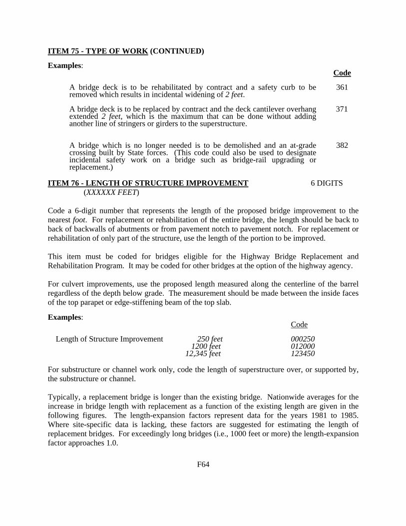
ITEM 75 - TYPE OF WORK (CONTINUED) Examples:
Code A bridge deck is to be rehabilitated by contract and a safety curb to be removed which results in incidental widening of 2 feet.
361
A bridge deck is to be replaced by contract and the deck cantilever overhang extended 2 feet, which is the maximum that can be done without adding another line of stringers or girders to the superstructure.
371
A bridge which is no longer needed is to be demolished and an at-grade crossing built by State forces. (This code could also be used to designate incidental safety work on a bridge such as bridge-rail upgrading or replacement.)
382
ITEM 76 - LENGTH OF STRUCTURE IMPROVEMENT 6 DIGITS (XXXXXX FEET) Code a 6-digit number that represents the length of the proposed bridge improvement to the nearest foot. For replacement or rehabilitation of the entire bridge, the length should be back to back of backwalls of abutments or from pavement notch to pavement notch. For replacement or rehabilitation of only part of the structure, use the length of the portion to be improved. This item must be coded for bridges eligible for the Highway Bridge Replacement and Rehabilitation Program. It may be coded for other bridges at the option of the highway agency. For culvert improvements, use the proposed length measured along the centerline of the barrel regardless of the depth below grade. The measurement should be made between the inside faces of the top parapet or edge-stiffening beam of the top slab. Examples: Code Length of Structure Improvement 250 feet 000250 1200 feet 012000 12,345 feet 123450 For substructure or channel work only, code the length of superstructure over, or supported by, the substructure or channel. Typically, a replacement bridge is longer than the existing bridge. Nationwide averages for the increase in bridge length with replacement as a function of the existing length are given in the following figures. The length-expansion factors represent data for the years 1981 to 1985. Where site-specific data is lacking, these factors are suggested for estimating the length of replacement bridges. For exceedingly long bridges (i.e., 1000 feet or more) the length-expansion factor approaches 1.0. F64
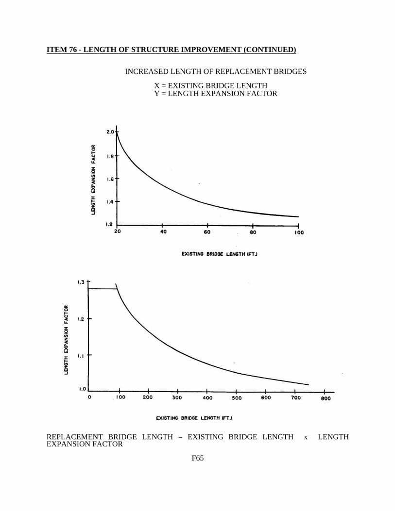
ITEM 76 - LENGTH OF STRUCTURE IMPROVEMENT (CONTINUED) INCREASED LENGTH OF REPLACEMENT BRIDGES X = EXISTING BRIDGE LENGTH Y = LENGTH EXPANSION FACTOR
REPLACEMENT BRIDGE LENGTH = EXISTING BRIDGE LENGTH x LENGTH EXPANSION FACTOR F65

ITEM 77 THROUGH ITEM 89 (Reserved) ITEM 90 - INSPECTION DATE 4 DIGITS Record the month and year that the last routine inspection of the structure was performed. This inspection date may be different from those recorded in Item 93 - Critical Feature Inspection Date. Code a 4-digit number to represent the month and year. The number of the month should be coded in the first 2 digits with a leading zero as required and the last 2 digits of the year coded as the third and fourth digits of the field. Examples: Code Inspection date November 1992 1192 March 1994 0394 ITEM 91 - DESIGNATED INSPECTION FREQUENCY 2 DIGITS Code 2 digits to represent the number of months between designated inspections of the structure. A leading zero shall be coded as required. This interval is usually determined by the individual in charge of the inspection program. For posted, understrength bridges, this interval should be substantially less than the 24-month standard. The designated inspection interval could vary from inspection to inspection depending on the condition of the bridge at the time of inspection. EXAMPLES: Code Posted bridge with heavy truck traffic 01 and questionable structural details which is designated to be inspected each month Bridge is scheduled to be inspected 24 every 24 months It should be noted that bridges will also require special non-scheduled inspections after unusual physical traumas such as floods, earthquakes, fires or collisions. These special inspections may range from a very brief visual examination to a detailed in-depth evaluation depending upon the nature of the trauma. For example, when a substructure pier or abutment is struck by an errant vehicle, in most cases only a visual examination of the bridge is necessary. After major collisions or earthquakes, in-depth inspections may be warranted as directed by the engineer in overall charge of the program. After and during severe floods, the stability of the substructure of bridges may have to be determined by probing, underwater sensors or other appropriate measures. Underwater inspection by divers may be required for some scour critical bridges immediately after floods. See Item 113 - Scour Critical Bridges.
F66

ITEM 92 - CRITICAL FEATURE INSPECTION 9 DIGITS Using a series of 3-digit code segments, denote critical features that need special inspections or special emphasis during inspections and the designated inspection interval in months as determined by the individual in charge of the inspection program. The designated inspection interval could vary from inspection to inspection depending on the condition of the bridge at the time of inspection. Segment Description Length 92A Fracture Critical Details 3 digits 92B Underwater Inspection 3 digits 92C Other Special Inspection 3 digits For each segment of Item 92A, B, and C, code the first digit Y for special inspection or emphasis needed and code N for not needed. The first digit of Item 92A, B, and C must be coded for all structures to designate either a yes or no answer. Those bridges coded with a Y in Item 92A or B should be the same bridges contained in the Master Lists of fracture critical and special underwater inspection bridges. In the second and third digits of each segment, code a 2-digit number to indicate the number of months between inspections only if the first digit is coded Y. If the first digit is coded N, the second and third digits are left blank. Current guidelines for the maximum allowable interval between inspections can be summarized as follows:
Fracture Critical Details 24 months Underwater Inspection 60 months Other Special Inspections 60 months
Examples:
Item Code A 2-girder system structure which is being inspected yearly and no other special inspections are required.
92A 92B 92C
Y12 N_ N_
A structure where both fracture critical and underwater inspection are being performed on a 1-year interval. Other special inspections are not required.
92A 92B 92C
Y12 Y12 N_
A structure has been temporarily shored and is being inspected on a 6-month interval. Other special inspections are not required.
92A 92B 92C
N_ N_ Y06
NOTE: In New Jersey, the “Other Special Inspection” field is used to indicate the need for Interim Inspections.
F67
2000

ITEM 93 - CRITICAL FEATURE INSPECTION DATE 12 DIGITS Code only if the first digit of Item 92A, B, or C is coded Y for yes. Record as a series of 4-digit code segments, the month and year that the last inspection of the denoted critical feature was performed. Segment Description Length 93A Fracture Critical Details 4 digits 93B Underwater Inspection 4 digits 93C Other Special Inspection 4 digits For each segment of this item, when applicable, code a 4-digit number to represent the month and year. The number of the month should be coded in the first 2 digits with a leading zero as required and the last 2 digits of the year coded as the third and fourth digits of the field. If the first digit of any part of Item 92 is coded N, then the corresponding part of this item shall be blank. Examples:
Item Code A structure has fracture critical members which were last inspected in March 1986. It does not require underwater or other special feature inspections.
93A 93B 93C
0386 (blank) (blank)
A structure has no fracture critical details, but requires underwater inspection and has other special features (for example, a temporary support) for which the State requires special inspection. The last underwater inspection was done in April 1986 and the last special feature inspection was done in November 1985.
93A 93B 93C
(blank) 0486 1185
ITEM 94 - BRIDGE IMPROVEMENT COST 6 DIGITS Code a 6-digit number to represent the estimated cost of the proposed bridge or major structure improvements in thousands of dollars. This cost shall include only bridge construction costs, excluding roadway, right of way, detour, demolition, preliminary engineering, etc. Code the base year for the cost in Item 97 - Year of Improvement Cost Estimate. Do not use this item for estimating maintenance costs. This item must be coded for bridges eligible for the Highway Bridge Replacement and Rehabilitation Program. It may be coded for other bridges at the option of the highway agency. Examples: Code Bridge Improvement Cost $ 55,850 00056 $ 250,000 000250 $7,451,233 007451
F68

ITEM 94 - BRIDGE IMPROVEMENT COST (CONTINUED) Nationally, the deck area of replaced bridges is averaging 2.2 times the deck area before replacement. The deck area of rehabilitated bridges is averaging 1.5 times the deck area before rehabilitation. Widening square meter costs are typically 1.8 times the square meter cost of new bridges with similar spans. For example, if the average cost of a new bridge is $50 per square foot, the average cost of the widened area would be $90 per square foot. Each highway agency is encouraged to use its best available information and established procedures to determine bridge improvement costs. In the absence of these procedures, the highway agency may wish to use the following procedure as a guide in preparing bridge improvement cost estimates. Apply a construction unit cost to the proposed bridge area developed by using (1) current State deck geometry design standards and (2) proposed bridge length from Item 76 - Length of Structure Improvement. ITEM 95 - ROADWAY IMPROVEMENT COST 6 DIGITS Code a 6-digit number to represent the cost of the proposed roadway improvement in thousands of dollars. This shall include only roadway construction costs, excluding bridge, right-of-way, detour, extensive roadway realignment costs, preliminary engineering, etc. Code the base year for the cost in Item 97 - Year of Improvement Cost Estimate. Do not use this item for estimating maintenance costs. This item must be coded for bridges eligible for the Highway Bridge Replacement and Rehabilitation Program. It may be coded for other bridges at the option of the highway agency. In the absence of a procedure for estimating roadway improvement costs, a guide of 10 percent of the bridge costs is suggested. ITEM 96 - TOTAL PROJECT COST 6 DIGITS Code a 6-digit number to represent the total project cost in thousands of dollars, including incidental costs not included in Items 94 and 95. This item should include all costs normally associated with the proposed bridge improvement project. The Total Project Cost will therefore usually be greater than the sum of Items 94 and 95. Code the base year for the cost in Item 97 - Year of Improvement Cost Estimate. Do not use this item for coding maintenance costs. This item must be coded for bridges eligible for the Highway Bridge Replacement and Rehabilitation Program. It may be coded for other bridges at the option of the highway agency. In the absence of a procedure for estimating the total project cost, a guide of 150 percent of the bridge cost is suggested.
F69

ITEM 97 - YEAR OF IMPROVEMENT COST ESTIMATE 4 DIGITS Record and code the year that the costs of work estimated in Item 94 - Bridge Improvement Cost, Item 95 - Roadway Improvement Cost, and Item 96 - Total Project Cost were based upon. This date and the data provided for Item 94 through Item 96 must be current; that is, Item 97 shall be no more than 8 years old. Examples: Code Year of Cost Estimate 1994 costs 1994 2000 costs 2000 ITEM 98 - BORDER BRIDGE 5 DIGITS Use this item to indicate structures crossing borders of States. Code a 5-digit number composed of 2 segments specifying the percent responsibility for improvements to the existing structure when it is on a border with a neighboring State. Code the first 3 digits with the neighboring State code using State codes listed in Item 1 - State Code. Code the fourth and fifth digits with the percentage of total deck area of the existing bridge that the neighboring State is responsible for funding.
Segment Description Length 98A Neighboring State Code 3 digits 98B Percent Responsibility 2 digits
If a neighboring State codes the structure and accepts 100% of the responsibility, but your State still codes a record for the structure, then Item 98B in your State's record should be coded 99 to represent that your State has no responsibility for the structure. For the special case of a structure on the border with Canada or Mexico, code the State code value = CAN or MEX respectively. If structure is not on a border, leave blank. Examples:
Code
A structure connects your State with New Jersey and New Jersey is responsible for funding 45 percent of future improvement costs.
34245
A structure connects your State with Mexico and Mexico is not responsible for any funding of future improvement costs.
MEX00
F70
ITEM 99 - BORDER BRIDGE STRUCTURE NUMBER 15 DIGITS Code the neighboring State's 15-digit National Bridge Inventory structure number for any structure noted in Item 98 - Border Bridge. This number must match exactly the neighboring State's submitted NBI structure number. The entire 15-digit field must be accounted for including zeros and blank spaces whether they are leading, trailing, or embedded in the 15-digit field. If Item 98 is blank, this item is blank. In the above example where Mexico (or a neighboring State) has 00% responsibility, and, if there is no NBI Structure Number in that State's inventory file, then the entire 15-digit field shall be coded zeroes. ITEM 100 - STRAHNET HIGHWAY DESIGNATION 1 DIGIT This item shall be coded for all records in the inventory. For the purposes of this item, the STRAHNET Connectors are considered included in the term STRAHNET. For the inventory route identified in Item 5, indicate STRAHNET highway conditions using one of the following codes:
Code Description 0 The inventory route is not a STRAHNET route.
1 The inventory route is on a Interstate STRAHNET route.
2 The inventory route is on a Non-Interstate STRAHNET route.
3 The inventory route is on a STRAHNET connector route.
NOTE: Refer to page SB-1 of this Guide for additional information.
F71

ITEM 101 - PARALLEL STRUCTURE DESIGNATION 1 DIGIT Code this item to indicate situations where separate structures carry the inventory route in opposite directions of travel over the same feature. The lateral distance between structures has no bearing on the coding of this item. One of the following codes shall be used:
Code Description R The right structure of parallel bridges carrying the
roadway in the direction of the inventory. (For a STRAHNET highway, this is west to east and south to north.)
L The left structure of parallel bridges. This structure carries traffic in the opposite direction.
N No parallel structure exists. Example: Code Structure #1 R Structure #2 L ITEM 102 - DIRECTION OF TRAFFIC 1 DIGIT Code the direction of traffic of the inventory route identified in Item 5 as a 1-digit number using one of the codes below. This item must be compatible with other traffic-related items such as Item 28A Lanes on the Structure, Item 29 - Average Daily Traffic, Item 47 - Total Horizontal Clearance and Item 51 - Bridge Roadway Width, Curb-to-Curb. Code Description 0 Highway traffic not carried 1 1-way traffic 2 2-way traffic 3 One lane bridge for 2-way traffic
F72

ITEM 103 - TEMPORARY STRUCTURE DESIGNATION 1 DIGIT Code this item to indicate situations where temporary structures or conditions exist. This item should be blank if not applicable. Code Description T Temporary structure(s) or conditions exist. Temporary structure(s) or conditions are those which are required to facilitate traffic flow. This may occur either before or during the modification or replacement of a structure found to be deficient. Such conditions include the following: ! Bridges shored up, including additional temporary supports. ! Temporary repairs made to keep a bridge open. ! Temporary structures, temporary runarounds or bypasses. ! Other temporary measures, such as barricaded traffic lanes to keep the bridge open. Any repaired structure or replacement structure which is expected to remain in place without further project activity, other than maintenance, for a significant period of time shall not be considered temporary. Under such conditions, that structure, regardless of its type, shall be considered the minimum adequate to remain in place and evaluated accordingly. If this item is coded T, then all data recorded for the structure shall be for the condition of the structure without temporary measures, except for the following items which shall be for the temporary structure: Item 10 - Inventory Route, Minimum Vertical Clearance 41 - Structure Open, Posted, or Closed to Traffic
47 - Inventory Route, Total Horizontal Clearance 53 - Minimum Vertical Clearance Over Bridge Roadway 54 - Minimum Vertical Underclearance 55 - Minimum Lateral Underclearance on Right 56 - Minimum Lateral Underclearance on Left 70 - Bridge Posting
F73

ITEM 104 - HIGHWAY SYSTEM OF THE INVENTORY ROUTE 1 DIGIT This item is to be coded for all records in the inventory. For the inventory route identified in Item 5, indicate whether the inventory route is on the National Highway System (NHS) or not on that system. Initially, this code shall reflect an inventory route on the NHS "Interim System" description in Section 1006(a) of the 1991 ISTEA. Upon approval of the NHS by Congress, the coding is to reflect the approved NHS. Use one of the following codes: Code Description 0 Inventory Route is not on the NHS 1 Inventory Route is on the NHS ITEM 105 - FEDERAL LANDS HIGHWAYS 1 DIGIT Structures owned by State and local jurisdictions on roads which lead to and traverse through federal lands sometimes require special coded unique identification because they are eligible to receive funding from the Federal Lands Highway Program. One of the following codes shall be used: Code Description 0 Not applicable 1 Indian Reservation Road (IRR) 2 Forest Highway (FH) 3 Land Management Highway System (LMHS) 4 Both IRR and FH 5 Both IRR and LMHS 6 Both FH and LMHS 9 Combined IRR, FH and LMHS
ITEM 106 - YEAR RECONSTRUCTED 4 DIGITS Record and code the year of most recent reconstruction of the structure. Code all 4 digits of the latest year in which reconstruction of the structure was completed. If there has been no reconstruction code 0000. For a bridge to be defined as reconstructed, the type of work performed, whether or not it meets current minimum standards, must have been eligible for funding under any of the Federal-aid funding categories. The eligibility criteria would apply to the work performed regardless of whether all State or local funds or Federal-aid funds were used. Some types of eligible work not to be considered as reconstruction are listed:
- Safety feature replacement or upgrading (for example, bridge rail, approach guardrail or impact attenuators).
- Painting of structural steel.
F74

ITEM 106 - YEAR RECONSTRUCTED (CONTINUED)
- Overlay of bridge deck as part of a larger highway surfacing project (for example, overlay carried across bridge deck for surface uniformity without additional bridge work).
- Utility work.
- Emergency repair to restore structural integrity to the previous status following an
accident.
- Retrofitting to correct a deficiency which does not substantially alter physical geometry or increase the load-carrying capacity.
- Work performed to keep a bridge operational while plans for complete rehabilitation
or replacement are under preparation (for example, adding a substructure element or extra girder).
Example: Code Reconstruction completed 1970 1970 ITEM 107 - DECK STRUCTURE TYPE 1 DIGIT Record the type of deck system on the bridge. If more than one type of deck system is on the bridge, code the most predominant. Code N for a filled culvert or arch with the approach roadway section carried across the structure. Use one of the following codes: Code Description 1 Concrete Cast-in-Place 2 Concrete Precast Panels 3 Open Grating 4 Closed Grating 5 Steel plate (includes orthotropic) 6 Corrugated Steel 7 Aluminum 8 Wood or Timber 9 Other N Not applicable ITEM 108 - WEARING SURFACE/PROTECTIVE SYSTEM 3 DIGITS Information on the wearing surface and protective system of the bridge deck shall be coded using a 3-digit code composed of 3 segments. Segment Description Length 108A Type of Wearing Surface 1 digit 108B Type of Membrane 1 digit 108C Deck Protection 1 digit F75

ITEM 108 - WEARING SURFACE/PROTECTIVE SYSTEM (CONT'D) 1st Digit - Type of Wearing Surface (Item 108A):
Code Description 1 Monolithic Concrete (concurrently placed with structural deck) 2 Integral Concrete (separate non-modified layer of concrete added to
structural deck) 3 Latex Concrete or similar additive 4 Low Slump Concrete 5 Epoxy Overlay 6 Bituminous 7 Wood or Timber 8 Gravel 9 Other 0 None (no additional concrete thickness or wearing surface is included
in the bridge deck) N Not Applicable (applies only to structures with no deck)
2nd Digit - Type of Membrane (Item 108B):
Code Description 1 Built-up 2 Preformed Fabric 3 Epoxy 8 Unknown 9 Other 0 None N Not Applicable (applies only to structures with no deck)
3rd Digit - Deck Protection (Item 108C):
Code Description 1 Epoxy Coated Reinforcing 2 Galvanized Reinforcing 3 Other Coated Reinforcing 4 Cathodic Protection 6 Polymer Impregnated 7 Internally Sealed 8 Unknown 9 Other 0 None N Not Applicable (applies only to structures with no deck)
F76

ITEM 109 - AVERAGE DAILY TRUCK TRAFFIC (XX PERCENT) 2 DIGITS Code a 2-digit percentage that shows the percentage of Item 29 - Average Daily Traffic that is truck traffic. Do not include vans, pickup trucks and other light delivery trucks in this percentage. If this information is not available, an estimate which represents the average percentage for the category of road carried by the bridge may be used. May be left blank if Item 29 - Average Daily Traffic is not greater than 100. Examples: Code Average Daily Traffic 7% trucks 07 12% trucks 12 NOTE: Refer to page SA-3 of this Guide for additional information. ITEM 110 - DESIGNATED NATIONAL NETWORK 1 DIGIT The national network for trucks includes most of the Interstate System and those portions of Federal-Aid highways identified in the Code of Federal Regulations (23 CFR 658). The national network for trucks is available for use by commercial motor vehicles of the dimensions and configurations described in these regulations. For the inventory route identified in Item 5, indicate conditions using one of the following codes: Code Description 0 The inventory route is not part of the national network for trucks. 1 The inventory route is part of the national network for trucks. NOTE: Refer to page SA-5 of this Guide for additional information. ITEM 111 - PIER OR ABUTMENT PROTECTION (FOR NAVIGATION) 1 DIGIT If Item 38 - Navigation Control has been coded 1, use the codes below to indicate the presence and adequacy of pier or abutment protection features such as fenders, dolphins, etc. The condition of the protection devices may be a factor in the overall evaluation of Item 60 - Substructure. If Item 38 - Navigation Control has been coded 0 or N, leave blank to indicate not applicable.
Code Description 1 Navigation protection not required 2 In place and functioning 3 In place but in a deteriorated condition 4 In place but reevaluation of design suggested 5 None present but reevaluation suggested
F77

ITEM 112 - NBIS BRIDGE LENGTH 1 DIGIT Does this structure meet or exceed the minimum length specified to be designated as a bridge for National Bridge Inspection Standards purposes? The following definition of a bridge is to be used:
A structure including supports erected over a depression or an obstruction, such as water, highway, or railway, and having a track or passageway for carrying traffic or other moving loads, and having an opening measured along the center of the roadway of more than 20 feet* between undercopings of abutments or spring lines of arches, or extreme ends of openings for multiple boxes; it may also include multiple pipes, where the clear distance between openings is less than half of the smaller contiguous opening. * (6.1 meters).
Code Description Y Yes N No
Examples:
(1) Item 112 - NBIS Bridge Length
F78

ITEM 112 – NBIS BRIDGE LENGTH (CONTINUED) Examples:
(1) Item 112 - NBIS Bridge Length F79
Roadway

ITEM 113 - SCOUR CRITICAL BRIDGES 1 DIGIT Use a single-digit code as indicated below to identify the current status of the bridge regarding its vulnerability to scour. Evaluations shall be made by hydraulic/geotechnical/structural engineers. Guidance on conducting a scour evaluation is included in the FHWA Technical Advisory T5140.23 titled, "Evaluating Scour at Bridges." Detailed engineering guidance is provided in the Hydraulic Engineering Circular 18 titled “Evaluating Scour at Bridges.” Whenever a rating factor of 2 or below is determined for this item, the rating factor for Item 60 - Substructure and other affected items (i.e., load ratings, superstructure rating) should be revised to reflect the severity of observed scour and resultant damage to the bridge. A plan of action should be developed for each scour critical bridge (see FHWA Technical Advisory T5140.23, HEC 18 and HEC 23). A scour critical bridge is one with abutment or pier foundations rated as unstable due to (1) observed scour at the bridge site (rating factor of 2, 1 or 0) or (2) a scour potential as determined from a scour evaluation study (rating factor of 3). It is assumed that the coding of this Item has been based on engineering evaluation, which includes consultation of the NBIS field inspection findings. Code Description N Bridge not over waterway.
U Bridge with "unknown" foundation that has not been evaluated for scour. Until risk can
be determined, a plan of action should be developed and implemented to reduce the risk to users from a bridge failure during and immediately after a flood event (see HEC 23).
T Bridge over "tidal" waters that has not been evaluated for scour, but considered low risk. Bridge will be monitored with regular inspection cycle and with appropriate underwater inspections until an evaluation is performed. ("Unknown" foundations in "tidal" waters should be coded U.)
9 Bridge foundations (including piles) on dry land well above flood water elevations.
8 Bridge foundations determined to be stable for the assessed or calculated scour
condition. Scour is determined to be above top of footing (Example A) by assessment (i.e., bridge foundations are on rock formations that have been determined to resist scour within the service life of the bridge 4), by calculation or by installation of properly designed countermeasures (see HEC 23).
7 Countermeasures have been installed to mitigate an existing problem with scour and to reduce the risk of bridge failure during a flood event. Instructions contained in a plan of action have been implemented to reduce the risk to users from a bridge failure during or immediately after a flood event. Bridge is no longer scour critical.
6 Scour calculation/evaluation has not been made. (Use only to describe case where bridge has not yet been evaluated for scour potential.)
(codes continued on the next page)
F80

ITEM 113 - SCOUR CRITICAL BRIDGES (CONTINUED) Code Description
5 Bridge foundations determined to be stable for assessed or calculated scour conditions. Scour is determined to be within the limits of footing or piles (Example B) by assessment (i.e., bridge foundations are on rock formations that have been determined to resist scour within the service life of the bridge), by calculations or by installation of properly designed countermeasures (see HEC 23).
4 Bridge foundations determined to be stable for assessed or calculated scour conditions.
field review indicates action is required to protect exposed foundations (see HEC 23).
3 Bridge is scour critical; bridge foundations determined to be unstable for assessed or calculated scour conditions:
- Scour within limits of footing or piles. (Example B) - Scour below spread-footing base or pile tips. (Example C) 2 Bridge is scour critical; field review indicates that extensive scour has occurred at
bridge foundations, which are determined to be unstable by: -a comparison of calculated scour and observed scour during the bridge inspection, or -an engineering evaluation of the observed scour conditions reported by the bridge
inspector. 1 Bridge is scour critical; field review indicates that failure of piers/abutments is
imminent. Failure is imminent based on: -a comparison of calculated scour and observed scour during the bridge inspection, or -an engineering evaluation of the observed scour conditions Reported by the bridge
inspector. 0 Bridge is scour critical. Bridge has failed and is closed to traffic.
References: 1-FHWA Technical Advisory T5140.23, Evaluating Scour at Bridges, dated October 28,1991. 2-HEC 18, Evaluating Scour at Bridges, Fourth Edition. 3-HEC 23, Bridge Scour and Stream Instability Countermeasures, Second Edition. 4-FHWA Memorandum “Scourability of Rock Formations,” dated July 19,1991.

F81

ITEM 113 - SCOUR CRITICAL BRIDGES (CONTINUED) Examples: CALCULATED SCOUR DEPTH ACTION NEEDED
F82

ITEM 114 - FUTURE AVERAGE DAILY TRAFFIC 6 DIGITS Code for all bridges the forecasted average daily traffic (ADT) for the inventory route identified in Item 5. This shall be projected at least 17 years but no more than 22 years from the year of inspection. The intent is to provide a basis for a 20-year forecast. This item may be updated anytime, but must be updated when the forecast falls below the 17-year limit. If planning data is not available, use the best estimate based on site familiarity. The future ADT must be compatible with the other items coded for the bridge. For example, parallel bridges with an open median are coded as follows: if Item 28 -Lanes On and Under the Structure and Item 51 - Bridge Roadway Width, Curb-to-Curb are coded for each bridge separately, then the future ADT must be coded for each bridge separately (not the total for the route). Examples: Code Future ADT 540 000540 15,600 015600 240,000 240000 ITEM 115 - YEAR OF FUTURE AVERAGE DAILY TRAFFIC 4 DIGITS Record and code the year represented by the future ADT in Item 114. The projected year of future ADT shall be at least 17 years but no more than 22 years from the year of inspection. Example: Code Year of Future ADT is 2014 2014 ITEM 116 - MINIMUM NAVIGATION VERTICAL CLEARANCE, 3 DIGITS VERTICAL LIFT BRIDGE (XXX FEET) Record and code as a 3-digit number in feet (rounded down), the minimum vertical clearance imposed at the site as measured above a datum that is specified on a navigation permit issued by a control agency. Code this item only for vertical lift bridges in the dropped or closed position, otherwise leave blank. Examples: Code Vertical Clearance 20.6 feet 020 24.2 feet 024
F83
GENERAL Inspection reports should generally include the following: 1. A statement of action taken, if any, pursuant to findings of inspection. 2. Any special findings stemming from the inspection and evaluation of fracture critical
members, underwater inspections, and special feature inspection. 3. Any features which should be monitored closely during subsequent inspections as should any
specific descriptions, instructions, or concerns. Measurements, sketches, diagrams, test results, or calculations should generally be included on separate sheets.
F84

APPENDIX A Metric Structure Inventory and Appraisal Sheet NOTE: The English Structure Inventory and Appraisal Sheet is not shown.

Appendix A OMB 2125-0501
Structure Inventory and Appraisal Sheet
FA-1

APPENDIX B
Sufficiency Rating Formula and Example
Appendix B Sufficiency Rating Formula and Example The sufficiency rating formula described herein is a method of evaluating highway bridge data by calculating four separate factors to obtain a numeric value which is indicative of bridge sufficiency to remain in service. The result of this method is a percentage in which 100 percent would represent an entirely sufficient bridge and zero percent would represent an entirely insufficient or deficient bridge. An asterisk prefix is used to identify a sufficiency rating that was calculated even though some essential data was missing or coded incorrectly. The Edit/Update Program will substitute a value for the unusable data (which will not lower the rating) and calculate the sufficiency rating. The asterisk is dropped when the unusable data is corrected. It is normal that all culverts with Bridge Roadway Width, Curb-to-Curb - Item 51 coded '0000' will have an asterisk prefixed sufficiency.
FB-1

Figure 1. Summary of Sufficiency Rating Factors
FB-2

Sufficiency Rating Formula
1. Structural Adequacy and Safety (55% maximum) a. Only the lowest rating code of Item 59, 60, or 62 applies. If Item 59 (Superstructure Rating) or Item 60 (Substructure Rating) is < 2 then A = 55% = 3 A = 40% = 4 A = 25% = 5 A = 10% If Item 59 and Item 60 = N and Item 62 (Culvert Rating) is < 2 then A = 55% = 3 A = 40% = 4 A = 25% = 5 A = 10% b. Reduction for Load Capacity: Calculate using the following formulas where IR is the Inventory Rating (HS Loading) in tons or use Figure 2: B = (36 - IR)1.5 x 0.2778 or If (36 - IR) < 0, then B = 0 "B" shall not be less than 0% nor greater than 55%. S1 = 55 - (A + B) S1 shall not be less than 0% nor greater than 55%.
FB-3

FIGURE 2. Reduction for Load Capacity
FB-4

2. Serviceability and Functional Obsolescence (30% maximum) a. Rating Reductions (13% maximum) If #58 (Deck Condition) is < 3 then A = 5% = 4 A = 3% = 5 A = 1% If #67 (Structural Evaluation) is < 3 then B = 4% = 4 B = 2% = 5 B = 1% If #68 (Deck Geometry) is < 3 then C = 4% = 4 C = 2% = 5 C = 1% If #69 (Underclearances) is < 3 then D = 4% = 4 D = 2% = 5 D = 1% If #71 (Waterway Adequacy) is < 3 then E = 4% = 4 E = 2% = 5 E = 1% If #72 (Approach Road Alignment) is < 3 then F = 4% = 4 F = 2% = 5 F = 1% J = (A + B + C + D + E + F) J shall not be less than 0% nor greater than 13%. b. Width of Roadway Insufficiency (15% maximum) Use the sections that apply: (1) applies to all bridges; (2) applies to 1-lane bridges only; (3) applies to 2 or more lane bridges; (4) applies to all except 1-lane bridges. Also determine X and Y: X (ADT/Lane) = Item 29 (ADT) first 2 digits of #28 (Lanes) Y (Width/Lane)* = Item 51 (Bridge Rdwy. Width) first 2 digits of #28 (Lanes) *A value of 36 Feet will be substituted when item 51 is coded 0000 or not numeric.
FB-5 2000
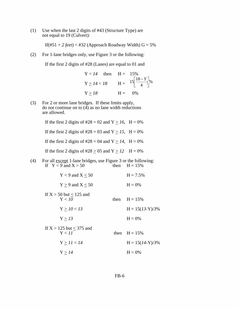
%4
1815 ⎥⎦⎤
⎢⎣⎡ −Y
(1) Use when the last 2 digits of #43 (Structure Type) are not equal to 19 (Culvert): If(#51 + 2 feet) < #32 (Approach Roadway Width) G = 5% (2) For 1-lane bridges only, use Figure 3 or the following: If the first 2 digits of #28 (Lanes) are equal to 01 and Y < 14 then H = 15% Y > 14 < 18 H = Y > 18 H = 0% (3) For 2 or more lane bridges. If these limits apply, do not continue on to (4) as no lane width reductions are allowed. If the first 2 digits of #28 = 02 and Y > 16, H = 0% If the first 2 digits of #28 = 03 and Y > 15, H = 0% If the first 2 digits of #28 = 04 and Y > 14, H = 0% If the first 2 digits of #28 > 05 and Y > 12 H = 0% (4) For all except 1-lane bridges, use Figure 3 or the following: If Y < 9 and X > 50 then H = 15% Y < 9 and X < 50 H = 7.5% Y > 9 and X < 50 H = 0% If X > 50 but < 125 and Y < 10 then H = 15% Y > 10 < 13 H = 15(13-Y)/3% Y > 13 H = 0% If X > 125 but < 375 and Y < 11 then H = 15% Y > 11 < 14 H = 15(14-Y)/3% Y > 14 H = 0%
FB-6

Figure 3. Width of Roadway Insufficiency
FB-7
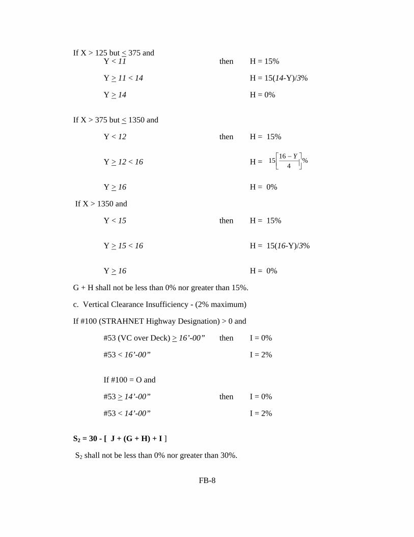
%4
1615 ⎥⎦⎤
⎢⎣⎡ − Y
If X > 125 but < 375 and Y < 11 then H = 15% Y > 11 < 14 H = 15(14-Y)/3% Y > 14 H = 0% If X > 375 but < 1350 and Y < 12 then H = 15% Y > 12 < 16 H = Y > 16 H = 0% If X > 1350 and Y < 15 then H = 15% Y > 15 < 16 H = 15(16-Y)/3% Y > 16 H = 0% G + H shall not be less than 0% nor greater than 15%. c. Vertical Clearance Insufficiency - (2% maximum) If #100 (STRAHNET Highway Designation) > 0 and #53 (VC over Deck) > 16’-00” then I = 0% #53 < 16’-00” I = 2% If #100 = O and #53 > 14’-00” then I = 0% #53 < 14’-00” I = 2% S2 = 30 - [ J + (G + H) + I ] S2 shall not be less than 0% nor greater than 30%.
FB-8

⎥⎦⎤
⎢⎣⎡
xK
thDetourLengxADT
000,200
(19#)(29#15
3. Essentiality for Public Use (15% maximum) a. Determine: S1 + S2 K = _________ 85
b. Calculate:
A = "A" shall not be less than 0% nor greater than 15%. c. STRAHNET Highway Designation: If #100 is > 0 then B = 2% If #100 = 0 then B = 0% S3 = 15 - (A + B) S3 shall not be less than 0% nor greater than 15%. 4. Special Reductions (Use only when S1 + S2 + S3 > 50) a. Detour Length Reduction, use Figure 4 or the following: A = (#19)4 x (5.205 x 10-8) "A" shall not be less than 0% nor greater than 5%. b. If the 2nd and 3rd digits of #43 (Structure Type, Main) are equal to 10, 12, 13, 14, 15, 16, or 17; then B = 5% c. If 2 digits of #36 (Traffic Safety Features) = 0 C = 1% If 3 digits of #36 = 0 C = 2% If 4 digits of #36 = 0 C = 3% S4 = A + B + C S4 shall not be less than 0% nor greater than 13%. _________________________________________________________________ Sufficiency Rating = S1 + S2 + S3 - S4 The Rating shall not be less than 0% nor greater than 100%.
FB-9

Figure 4. Special Reduction for Detour Length
FB-10
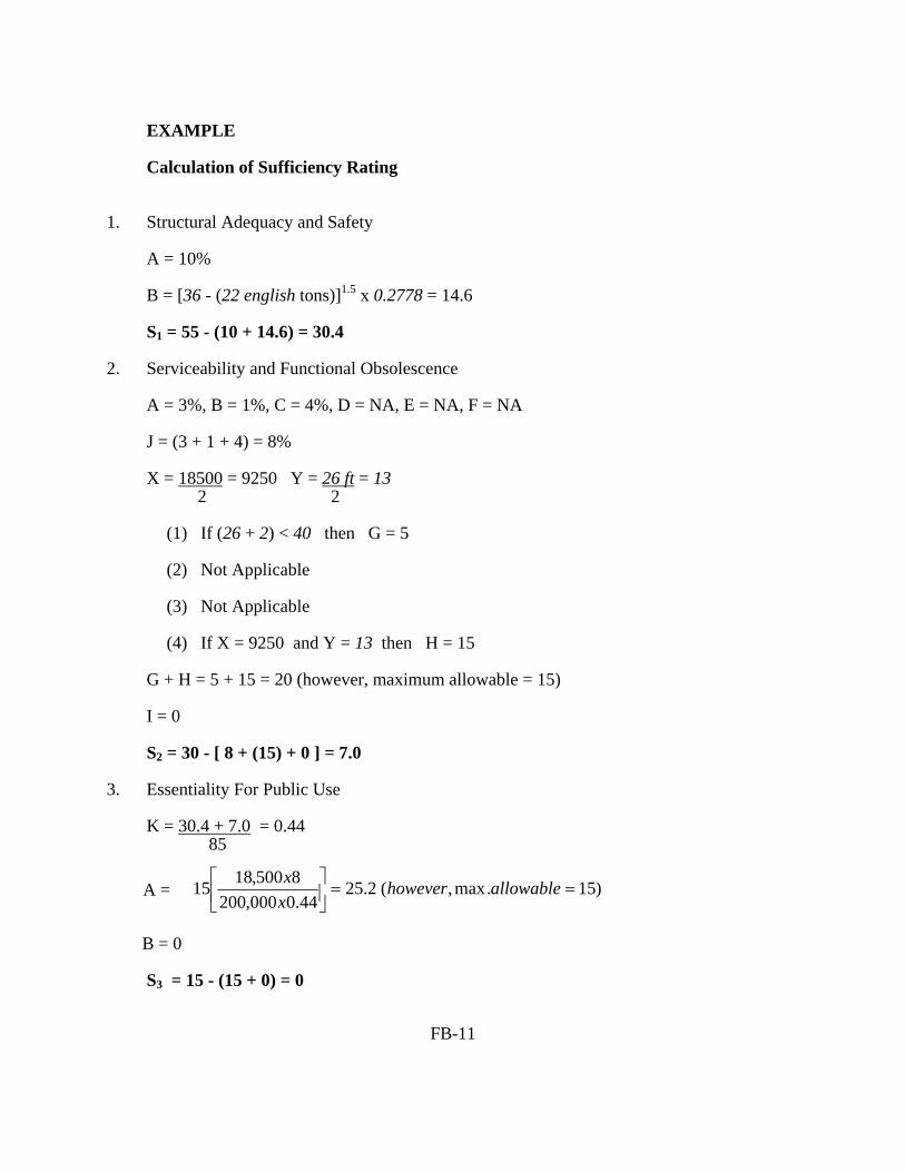
EXAMPLE Calculation of Sufficiency Rating 1. Structural Adequacy and Safety A = 10% B = [36 - (22 english tons)]1.5 x 0.2778 = 14.6 S1 = 55 - (10 + 14.6) = 30.4 2. Serviceability and Functional Obsolescence A = 3%, B = 1%, C = 4%, D = NA, E = NA, F = NA J = (3 + 1 + 4) = 8% X = 18500 = 9250 Y = 26 ft = 13 2 2 (1) If (26 + 2) < 40 then G = 5 (2) Not Applicable (3) Not Applicable (4) If X = 9250 and Y = 13 then H = 15 G + H = 5 + 15 = 20 (however, maximum allowable = 15) I = 0 S2 = 30 - [ 8 + (15) + 0 ] = 7.0 3. Essentiality For Public Use K = 30.4 + 7.0 = 0.44 85
B = 0 S3 = 15 - (15 + 0) = 0
FB-11
)15.max,(2.2544.0000,200
8500,1815 ==⎥⎦
⎤⎢⎣
⎡ allowablehoweverxx
A =

4. Special Reductions S1 + S2 + S3 = (30.4 + 7.0 + 0.0) = 37.4 < 50 S4 = NA __________________________________________________________________ SUFFICIENCY RATING = 30.4 + 7.0 + 0.0 = 37.4 ____________________________________________________________
FB-12

FB-13

APPENDIX C National Bridge Inspection Standards Section 650.311 - The January 1979 Coding Guide has been superseded by a December 1988 Guide, which is superseded by this metric version of the Coding Guide.

74436 Federal Register / Vol. 69, No. 239 / Tuesday, December 14, 2004 / Rules and Regulations
1 The National Highway Institute training may be found at the following URL: http://www.nhi.fhwa.dot.gov./
imposes on the States. These requirements include the development of procedures for follow-up on critical findings.
In the NPRM published on September 9, 2003, the FHWA proposed a burden increase of 67,000 hours for the information collection, OMB control number 2125–0501, and invited interested parties to send comments regarding any aspect of these information collection requirements. Such comments could include, but were not limited to: (1) Whether the collection of information will be necessary for the performance of the functions of the FHWA, including whether the information will have practical utility; (2) the accuracy of the estimated burden; (3) ways to enhance the quality, utility, and clarity of the collection of information; and (4) ways to minimize the collection burden without reducing the quality of the information collected. The FHWA did not receive any comments in response to the proposed burden hour increase of 67,000 hours. The revision to the information collection, OMB control number 2125–0501, based on this final rule will increase the burden hours by only 2,080 hours, a much smaller amount than that originally proposed in the NPRM.
National Environmental Policy Act
The agency has analyzed this action for the purpose of the National Environmental Policy Act of 1969 (42 U.S.C. 4321) and has determined that this action will not have any effect on the quality of the environment.
Executive Order 13211 (Energy Effects)
We have analyzed this rule under Executive Order 13211, Actions Concerning Regulations That Significantly Affect Energy Supply, Distribution, or Use. We have determined that it is not a significant energy action under that order, because although it is a significant regulatory action under Executive Order 12866 it is not likely to have a significant adverse effect on the supply, distribution, or use of energy.
Regulation Identification Number
A regulation identification number (RIN) is assigned to each regulatory action listed in the Unified Agenda of Federal Regulations. The Regulatory Information Service Center publishes the Unified Agenda in April and October of each year. The RIN contained in the heading of this document can be used to cross-reference this action with the Unified Agenda.
List of Subjects in 23 CFR Part 650
Bridges, Grant Programs—transportation, Highways and roads, Incorporation by reference, Reporting and record keeping requirements.
Issued on: December 9, 2004.
Mary E. Peters,
Federal Highway Administrator.
n In consideration of the foregoing, the FHWA is amending title 23, Code of Federal Regulations, part 650, subpart C, as follows:
PART 650—BRIDGES, STRUCTURES, AND HYDRAULICS
n 1. The authority citation for part 650 continues to read as follows:
Authority: 23 U.S.C. 109 (a) and (h), 144, 151, 315, and 319; 33 U.S.C. 401, 491 et seq., 511 et seq.; 23 CFR 1.32; 49 CFR 1.48(b), E.O. 11988 (3 CFR, 1977 Comp. p. 117); Department of Transportation Order 5650.2 dated April 23, 1979 (44 FR 24678); sec. 161 of Public Law 97–424, 96 Stat. 2097, 3135; sec. 4(b) of Public Law 97–134, 95 Stat. 1699; and sec. 1057 of Public Law 102–240, 105 Stat. 2002; and sec. 1311 of Pub. L. 105–178, as added by Pub. L. 105–206, 112 Stat. 842 (1998).
n 2. Revise subpart C to read as follows:
Subpart C—National Bridge Inspection Standards
Sec. 650.301 Purpose. 650.303 Applicability. 650.305 Definitions. 650.307 Bridge inspection organization. 650.309 Qualifications of personnel. 650.311 Inspection frequency. 650.313 Inspection procedures. 650.315 Inventory. 650.317 Reference manuals.
Subpart C—National Bridge Inspection Standards
§ 650.301 Purpose.
This subpart sets the national standards for the proper safety inspection and evaluation of all highway bridges in accordance with 23 U.S.C. 151.
§ 650.303 Applicability.
The National Bridge Inspection Standards (NBIS) in this subpart apply to all structures defined as highway bridges located on all public roads.
§ 650.305 Definitions.
Terms used in this subpart are defined as follows:
American Association of State Highway and Transportation Officials (AASHTO) Manual. ‘‘Manual for Condition Evaluation of Bridges,’’ second edition, published by the American Association of State Highway and Transportation Officials
(incorporated by reference, see § 650.317).
Bridge. A structure including supports erected over a depression or an obstruction, such as water, highway, or railway, and having a track or passageway for carrying traffic or other moving loads, and having an opening measured along the center of the roadway of more than 20 feet between undercopings of abutments or spring lines of arches, or extreme ends of openings for multiple boxes; it may also include multiple pipes, where the clear distance between openings is less than half of the smaller contiguous opening.
Bridge inspection experience. Active participation in bridge inspections in accordance with the NBIS, in either a field inspection, supervisory, or management role. A combination of bridge design, bridge maintenance, bridge construction and bridge inspection experience, with the predominant amount in bridge inspection, is acceptable.
Bridge inspection refresher training. The National Highway Institute ‘‘Bridge Inspection Refresher Training Course’’ 1 or other State, local, or federally developed instruction aimed to improve quality of inspections, introduce new techniques, and maintain the consistency of the inspection program.
Bridge Inspector’s Reference Manual (BIRM). A comprehensive FHWA manual on programs, procedures and techniques for inspecting and evaluating a variety of in-service highway bridges. This manual may be purchased from the U.S. Government Printing Office, Washington, DC 20402 and from National Technical Information Service, Springfield, Virginia 22161, and is available at the following URL: http://www.fhwa.dot.gov/bridge/bripub.htm.
Complex bridge. Movable, suspension, cable stayed, and other bridges with unusual characteristics.
Comprehensive bridge inspection training. Training that covers all aspects of bridge inspection and enables inspectors to relate conditions observed on a bridge to established criteria (see the Bridge Inspector’s Reference Manual for the recommended material to be covered in a comprehensive training course).
Critical finding. A structural or safety related deficiency that requires immediate follow-up inspection or action.
Damage inspection. This is an unscheduled inspection to assess structural damage resulting from environmental factors or human actions.
VerDate jul<14>2003 21:13 Dec 13, 2004 Jkt 205001 PO 00000 Frm 00032 Fmt 4700 Sfmt 4700 E:\FR\FM\14DER1.SGM 14DER1FC-1

74437Federal Register / Vol. 69, No. 239 / Tuesday, December 14, 2004 / Rules and Regulations
Fracture critical member (FCM). A steel member in tension, or with a tension element, whose failure would probably cause a portion of or the entire bridge to collapse.
Fracture critical member inspection. A hands-on inspection of a fracture critical member or member components that may include visual and other nondestructive evaluation.
Hands-on. Inspection within arms length of the component. Inspection uses visual techniques that may be supplemented by nondestructive testing.
Highway. The term ‘‘highway’’ is defined in 23 U.S.C. 101(a)(11).
In-depth inspection. A close-up, inspection of one or more members above or below the water level to identify any deficiencies not readily detectable using routine inspection procedures; hands-on inspection may be necessary at some locations.
Initial inspection. The first inspection of a bridge as it becomes a part of the bridge file to provide all Structure Inventory and Appraisal (SI&A) data and other relevant data and to determine baseline structural conditions.
Legal load. The maximum legal load for each vehicle configuration permitted by law for the State in which the bridge is located.
Load rating. The determination of the live load carrying capacity of a bridge using bridge plans and supplemented by information gathered from a field inspection.
National Institute for Certification in Engineering Technologies (NICET). The NICET provides nationally applicable voluntary certification programs covering several broad engineering technology fields and a number of specialized subfields. For information on the NICET program certification contact: National Institute for Certification in Engineering Technologies, 1420 King Street, Alexandria, VA 22314–2794.
Operating rating. The maximum permissible live load to which the structure may be subjected for the load configuration used in the rating.
Professional engineer (PE). An individual, who has fulfilled education and experience requirements and passed rigorous exams that, under State licensure laws, permits them to offer engineering services directly to the public. Engineering licensure laws vary from State to State, but, in general, to become a PE an individual must be a graduate of an engineering program accredited by the Accreditation Board for Engineering and Technology, pass the Fundamentals of Engineering exam,
gain four years of experience working under a PE, and pass the Principles of Practice of Engineering exam.
Program Manager. The individual in charge of the program, that has been assigned or delegated the duties and responsibilities for bridge inspection, reporting, and inventory. The program manager provides overall leadership and is available to inspection team leaders to provide guidance.
Public road. The term ‘‘public road’’ is defined in 23 U.S.C. 101(a)(27).
Quality assurance (QA). The use of sampling and other measures to assure the adequacy of quality control procedures in order to verify or measure the quality level of the entire bridge inspection and load rating program.
Quality control (QC). Procedures that are intended to maintain the quality of a bridge inspection and load rating at or above a specified level.
Routine inspection. Regularly scheduled inspection consisting of observations and/or measurements needed to determine the physical and functional condition of the bridge, to identify any changes from initial or previously recorded conditions, and to ensure that the structure continues to satisfy present service requirements.
Routine permit load. A live load, which has a gross weight, axle weight or distance between axles not conforming with State statutes for legally configured vehicles, authorized for unlimited trips over an extended period of time to move alongside other heavy vehicles on a regular basis.
Scour. Erosion of streambed or bank material due to flowing water; often considered as being localized around piers and abutments of bridges.
Scour critical bridge. A bridge with a foundation element that has been determined to be unstable for the observed or evaluated scour condition.
Special inspection. An inspection scheduled at the discretion of the bridge owner, used to monitor a particular known or suspected deficiency.
State transportation department. The term ‘‘State transportation department’’ is defined in 23 U.S.C. 101(a)(34).
Team leader. Individual in charge of an inspection team responsible for planning, preparing, and performing field inspection of the bridge.
Underwater diver bridge inspection training. Training that covers all aspects of underwater bridge inspection and enables inspectors to relate the conditions of underwater bridge elements to established criteria (see the Bridge Inspector’s Reference Manual section on underwater inspection for the recommended material to be covered in
an underwater diver bridge inspection training course).
Underwater inspection. Inspection of the underwater portion of a bridge substructure and the surrounding channel, which cannot be inspected visually at low water by wading or probing, generally requiring diving or other appropriate techniques.
§ 650.307 Bridge inspection organization.
(a) Each State transportation department must inspect, or cause to be inspected, all highway bridges located on public roads that are fully or partially located within the State’s boundaries, except for bridges that are owned by Federal agencies.
(b) Federal agencies must inspect, or cause to be inspected, all highway bridges located on public roads that are fully or partially located within the respective agency responsibility or jurisdiction.
(c) Each State transportation department or Federal agency must include a bridge inspection organization that is responsible for the following:
(1) Statewide or Federal agencywide bridge inspection policies and procedures, quality assurance and quality control, and preparation and maintenance of a bridge inventory.
(2) Bridge inspections, reports, load ratings and other requirements of these standards.
(d) Functions identified in paragraphs (c)(1) and (2) of this section may be delegated, but such delegation does not relieve the State transportation department or Federal agency of any of its responsibilities under this subpart.
(e) The State transportation department or Federal agency bridge inspection organization must have a program manager with the qualifications defined in § 650.309(a), who has been delegated responsibility for paragraphs (c)(1) and (2) of this section.
§ 650.309 Qualifications of personnel.
(a) A program manager must, at a minimum:
(1) Be a registered professional engineer, or have ten years bridge inspection experience; and
(2) Successfully complete a Federal Highway Administration (FHWA) approved comprehensive bridge inspection training course.
(b) There are five ways to qualify as a team leader. A team leader must, at a minimum:
(1) Have the qualifications specified in paragraph (a) of this section; or
(2) Have five years bridge inspection experience and have successfully completed an FHWA approved comprehensive bridge inspection training course; or
VerDate jul<14>2003 21:13 Dec 13, 2004 Jkt 205001 PO 00000 Frm 00033 Fmt 4700 Sfmt 4700 E:\FR\FM\14DER1.SGM 14DER1FC-2
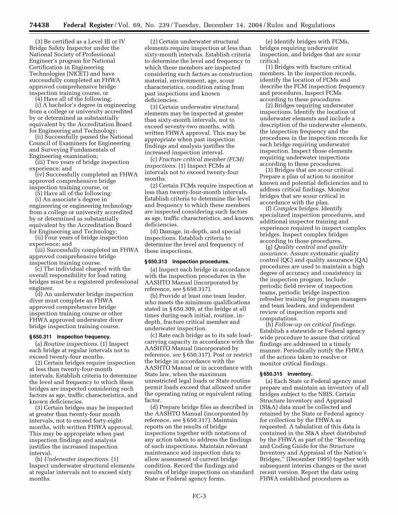
74438 Federal Register / Vol. 69, No. 239 / Tuesday, December 14, 2004 / Rules and Regulations
(3) Be certified as a Level III or IV Bridge Safety Inspector under the National Society of Professional Engineer’s program for National Certification in Engineering Technologies (NICET) and have successfully completed an FHWA approved comprehensive bridge inspection training course, or
(4) Have all of the following:(i) A bachelor’s degree in engineering
from a college or university accredited by or determined as substantially equivalent by the Accreditation Board for Engineering and Technology;
(ii) Successfully passed the National Council of Examiners for Engineering and Surveying Fundamentals of Engineering examination;
(iii) Two years of bridge inspection experience; and
(iv) Successfully completed an FHWA approved comprehensive bridge inspection training course, or
(5) Have all of the following: (i) An associate’s degree in
engineering or engineering technology from a college or university accredited by or determined as substantially equivalent by the Accreditation Board for Engineering and Technology;
(ii) Four years of bridge inspection experience; and
(iii) Successfully completed an FHWA approved comprehensive bridge inspection training course.
(c) The individual charged with the overall responsibility for load rating bridges must be a registered professional engineer.
(d) An underwater bridge inspection diver must complete an FHWA approved comprehensive bridge inspection training course or other FHWA approved underwater diver bridge inspection training course.
§ 650.311 Inspection frequency.
(a) Routine inspections. (1) Inspect each bridge at regular intervals not to exceed twenty-four months.
(2) Certain bridges require inspection at less than twenty-four-month intervals. Establish criteria to determine the level and frequency to which these bridges are inspected considering such factors as age, traffic characteristics, and known deficiencies.
(3) Certain bridges may be inspected at greater than twenty-four month intervals, not to exceed forty-eight-months, with written FHWA approval. This may be appropriate when past inspection findings and analysis justifies the increased inspection interval.
(b) Underwater inspections. (1) Inspect underwater structural elements at regular intervals not to exceed sixty months.
(2) Certain underwater structural elements require inspection at less than sixty-month intervals. Establish criteria to determine the level and frequency to which these members are inspected considering such factors as construction material, environment, age, scour characteristics, condition rating from past inspections and known deficiencies.
(3) Certain underwater structural elements may be inspected at greater than sixty-month intervals, not to exceed seventy-two months, with written FHWA approval. This may be appropriate when past inspection findings and analysis justifies the increased inspection interval.
(c) Fracture critical member (FCM) inspections. (1) Inspect FCMs at intervals not to exceed twenty-four months.
(2) Certain FCMs require inspection at less than twenty-four-month intervals. Establish criteria to determine the level and frequency to which these members are inspected considering such factors as age, traffic characteristics, and known deficiencies.
(d) Damage, in-depth, and special inspections. Establish criteria to determine the level and frequency of these inspections.
§ 650.313 Inspection procedures.
(a) Inspect each bridge in accordance with the inspection procedures in the AASHTO Manual (incorporated by reference, see § 650.317).
(b) Provide at least one team leader, who meets the minimum qualifications stated in § 650.309, at the bridge at all times during each initial, routine, in-depth, fracture critical member and underwater inspection.
(c) Rate each bridge as to its safe load-carrying capacity in accordance with the AASHTO Manual (incorporated by reference, see § 650.317). Post or restrict the bridge in accordance with the AASHTO Manual or in accordance with State law, when the maximum unrestricted legal loads or State routine permit loads exceed that allowed under the operating rating or equivalent rating factor.
(d) Prepare bridge files as described in the AASHTO Manual (incorporated by reference, see § 650.317). Maintain reports on the results of bridge inspections together with notations of any action taken to address the findings of such inspections. Maintain relevant maintenance and inspection data to allow assessment of current bridge condition. Record the findings and results of bridge inspections on standard State or Federal agency forms.
(e) Identify bridges with FCMs, bridges requiring underwater inspection, and bridges that are scour critical.
(1) Bridges with fracture critical members. In the inspection records, identify the location of FCMs and describe the FCM inspection frequency and procedures. Inspect FCMs according to these procedures.
(2) Bridges requiring underwater inspections. Identify the location of underwater elements and include a description of the underwater elements, the inspection frequency and the procedures in the inspection records for each bridge requiring underwater inspection. Inspect those elements requiring underwater inspections according to these procedures.
(3) Bridges that are scour critical. Prepare a plan of action to monitor known and potential deficiencies and to address critical findings. Monitor bridges that are scour critical in accordance with the plan.
(f) Complex bridges. Identify specialized inspection procedures, and additional inspector training and experience required to inspect complex bridges. Inspect complex bridges according to those procedures.
(g) Quality control and quality assurance. Assure systematic quality control (QC) and quality assurance (QA) procedures are used to maintain a high degree of accuracy and consistency in the inspection program. Include periodic field review of inspection teams, periodic bridge inspection refresher training for program managers and team leaders, and independent review of inspection reports and computations.
(h) Follow-up on critical findings. Establish a statewide or Federal agency wide procedure to assure that critical findings are addressed in a timely manner. Periodically notify the FHWA of the actions taken to resolve or monitor critical findings.
§ 650.315 Inventory.
(a) Each State or Federal agency must prepare and maintain an inventory of all bridges subject to the NBIS. Certain Structure Inventory and Appraisal (SI&A) data must be collected and retained by the State or Federal agency for collection by the FHWA as requested. A tabulation of this data is contained in the SI&A sheet distributed by the FHWA as part of the ‘‘Recording and Coding Guide for the Structure Inventory and Appraisal of the Nation’s Bridges,’’ (December 1995) together with subsequent interim changes or the most recent version. Report the data using FHWA established procedures as
VerDate jul<14>2003 21:13 Dec 13, 2004 Jkt 205001 PO 00000 Frm 00034 Fmt 4700 Sfmt 4700 E:\FR\FM\14DER1.SGM 14DER1FC-3

74439Federal Register / Vol. 69, No. 239 / Tuesday, December 14, 2004 / Rules and Regulations
1 This Interpretive Guidance focuses on the need to control risks arising out of the relationship between a Money Service Business and its foreign counterparty or agent. Under existing FinCEN regulations, only Money Service Business principals are required to register with FinCEN, and only Money Service Business principals establish the counterparty or agency relationships. 31 CFR 103.41. Accordingly, this Interpretive Guidance only applies to those Money Service Businesses required to register with FinCEN, that is, only those Money Service Businesses that may have a relationship with a foreign agent or counterparty.
outlined in the ‘‘Recording and Coding Guide for the Structure Inventory and Appraisal of the Nation’s Bridges.’’
(b) For routine, in-depth, fracture critical member, underwater, damage and special inspections enter the SI&A data into the State or Federal agency inventory within 90 days of the date of inspection for State or Federal agency bridges and within 180 days of the date of inspection for all other bridges.
(c) For existing bridge modifications that alter previously recorded data and for new bridges, enter the SI&A data into the State or Federal agency inventory within 90 days after the completion of the work for State or Federal agency bridges and within 180 days after the completion of the work for all other bridges.
(d) For changes in load restriction or closure status, enter the SI&A data into the State or Federal agency inventory within 90 days after the change in status of the structure for State or Federal agency bridges and within 180 days after the change in status of the structure for all other bridges.
§ 650.317 Reference manuals.
(a) The materials listed in this subpart are incorporated by reference in the corresponding sections noted. These incorporations by reference were approved by the Director of the Federal Register in accordance with 5 U.S.C. 552(a) and 1 CFR part 51. These materials are incorporated as they exist on the date of the approval, and notice of any change in these documents will be published in the Federal Register. The materials are available for purchase at the address listed below, and are available for inspection at the National Archives and Records Administration (NARA). These materials may also be reviewed at the Department of Transportation Library, 400 Seventh Street, SW., Washington, DC, in Room 2200. For information on the availability of these materials at NARA call (202) 741–6030, or go to the following URL: http://www.archives.gov/federal_register/code_of_federal_regulations/ibr_locations.html. In the event there is a conflict between the standards in this subpart and any of these materials, the standards in this subpart will apply.
(b) The following materials are available for purchase from the American Association of State Highway and Transportation Officials, Suite 249, 444 N. Capitol Street, NW., Washington, DC 20001. The materials may also be ordered via the AASHTO bookstore located at the following URL: http://www.aashto.org/aashto/home.nsf/FrontPage.
(1) The Manual for Condition Evaluation of Bridges, 1994, second edition, as amended by the 1995, 1996, 1998, and 2000 interim revisions, AASHTO, incorporation by reference approved for §§ 650.305 and 650.313.
(2) 2001 Interim Revision to the Manual for Condition Evaluation of Bridges, AASHTO, incorporation by reference approved for §§ 650.305 and 650.313.
(3) 2003 Interim Revision to the Manual for Condition Evaluation of Bridges, AASHTO, incorporation by reference approved for §§ 650.305 and 650.313.
[FR Doc. 04–27355 Filed 12–13–04; 8:45 am]
BILLING CODE 4910–22–P
DEPARTMENT OF THE TREASURY
31 CFR Part 103
Financial Crimes Enforcement Network; Interpretive Release 2004–1—Anti-Money Laundering Program Requirements for Money Services Businesses With Respect to Foreign Agents or Foreign Counterparties
AGENCY: Financial Crimes Enforcement Network (FinCEN), Treasury.
ACTION: Final rule; interpretive release.
SUMMARY: This Interpretive Release sets forth an interpretation of the regulation requiring Money Services Businesses that are required to register with FinCEN to establish and maintain anti-money laundering programs. Specifically, this Interpretive Release clarifies that the anti-money laundering program regulation requires such Money Services Businesses to establish adequate and appropriate policies, procedures and controls commensurate with the risk of money laundering and the financing of terrorism posed by their relationship with foreign agents or foreign counterparties of the Money Services Business.
DATES: Effective June 13, 2005.
FOR FURTHER INFORMATION CONTACT: Office of Regulatory Policy and Programs Division, 1–800–800–2877, Office of Chief Counsel (703) 905–3590 (not a toll free number).
SUPPLEMENTARY INFORMATION: Section 5318(h) of the Bank Secrecy Act, which is codified in subchapter II of chapter 53 of title 31, United States Code, requires every financial institution to establish an anti-money laundering program. The Bank Secrecy Act regulations define financial institution to include money service businesses. On April 29, 2002, FinCEN issued interim final rules-31
CFR 103.125-concerning the application of the anti-money laundering program requirement to money services businesses. 67 FR 21114.
List of Subjects in 31 CFR Part 103
Authority delegations (government agencies), bank, banking, currency, investigations, reporting and recordkeeping requirements.
Department of the Treasury
31 CFR Chapter I
Authority and Issuance
n For the reasons set forth in the preamble, part 103 of title 31 of the Code of Federal Regulations is amended as follows:
PART 103—FINANCIAL RECORDKEEPING AND REPORTING OF CURRENCY AND FOREIGN TRANSACTIONS
n 1. The authority citation for part 103 continues to read as follows:
Authority: 12 U.S.C. 1829b and 1951–1959: 31 U.S.C 5311–5314 and 5316–5332; title III, secs. 312, 313, 314, 319, 326, 352, Pub. L. 107–56, 115 Stat. 307, 12 U.S.C. 1786(q).
n 2. Part 103 is amended by adding a new appendix C to read as follows:
APPENDIX C TO PART 103—INTERPRETIVE RULES
Release No. 2004–01
This Interpretive Guidance sets forth our interpretation of the regulation requiring Money Services Businesses that are required to register with FinCEN to establish and maintain anti-money laundering programs. See 31 CFR 103.125. Specifically, this Interpretive Guidance clarifies that the anti-money laundering program regulation requires Money Services Businesses to establish adequate and appropriate policies, procedures, and controls commensurate with the risks of money laundering and the financing of terrorism posed by their relationship with foreign agents or foreign counterparties of the Money Services Business.1
Under existing Bank Secrecy Act regulations, we have defined Money Services Businesses to include five distinct types of financial services providers and the U.S. Postal Service: (1) Currency dealers or exchangers; (2) check cashers; (3) issuers of traveler’s checks, money orders, or stored
VerDate jul<14>2003 21:13 Dec 13, 2004 Jkt 205001 PO 00000 Frm 00035 Fmt 4700 Sfmt 4700 E:\FR\FM\14DER1.SGM 14DER1FC-4

APPENDIX D Commentary The 22 page commentary contained in the 1988 Coding Guide has not been included in this document. The following pages of commentary, however, show item by item changes caused by this revision.
Appendix D December 1994 Commentary This commentary provides a ready reference for item by item changes between the 1988 Coding Guide and this proposed revision. Items not specifically mentioned here are essentially unchanged except. Introduction ! Mentions new items and their use. ! References to Defense Bridges removed and STRAHNET added. ! Federal agencies specifically included in this Guide. ! Minor editorial changes and reference revisions have been made to bring the text up to date. Definition of Terms ! The order of the definitions has changed and the following added or modified:
(a) Bridge length has been converted to metric. The length of 20 feet has been changed to 6.1 meters. (b) Culvert. (i) Strategic Highway Corridor Network (STRAHNET). Replaces Defense
Items, which were dropped. (j) STRAHNET Connectors. (k) Indian Reservation Road definition has been added. (l) Land Management Highway System (LMHS) (m) Forest Highway (FH) (n) Forest Service Development Road. (o) Base Highway Network. (p) Highway Performance Monitoring System. (q) Conversion of Numerical Data (r) Rounding and Truncating of Numerical Data.
Item 2 - Highway Agency District ! Name of item changed to reflect inclusion of federal bridges. Item 5A - Record Type ! Clarification has been made for the case of 2 or more routes passing under a structure. ! Items 30, and 109 have been added to the list of items required to be coded for "under"
records.
FD-1

Item 6 - Features Intersected ! Item coding requirements have been clarified for "under" records. ! References to defense highway and FHPM 6-10-2 have been eliminated. ! Critical facilities are now STRAHNET and STRAHNET Connectors. Item 7 - Facility Carried by Structure ! Item coding requirements have been clarified for "under" records. ! Temporary use of this item for coding IRR has been changed to Item 105. Item 8 - Structure Number ! Closed median has been described. ! Additional emphasis has been given to the need to have all 15 digits filled. Item 11 - Mile Point ! Seven digits will be coded instead of six. Item 12 - Base Highway Network ! New item added for use in identifying Linear Referencing System (LRS). Item 13 - LRS Inventory Route, Subroute Number ! New item added for identifying LRS. Item 16 - Latitude and Item 17 - Longitude ! Number of digits have been expanded to 8 and 9 digits, respectively. ! The format of the item allows an increased precision of measurement (not mandatory) to
accommodate the use of the Global Positioning System (GPS). Current measuring methods and level of precision may continue to be used.
References to defense highways changed to STRAHNET. ! Location where measurement is taken must be compatible with the LRS. Item 20 - Toll ! Reference to Secretarial Agreement updated. Item 21 - Maintenance Responsibility and Item 22 - Owner ! Several federal agencies have been added.
FD-2

Item 26 - Functional Classification of Inventory Route ! This item is no longer compatible with Item 104 and appropriate revisions have been made. Item 28 - Lanes On and Under the Structure ! Text clarified for "under" records. ! Text has been added advising that any "1-lane" bridge 16 feet or greater in curb-to curb width
is evaluated as 2 lanes or more in Item 68 -Deck Geometry. Item 29 - Average Daily Traffic ! Text has been added explaining that if the bridge is closed, the coding is to be the actual
ADT from the period before the closure occurred. Item 30 - Year of Average Daily Traffic ! Field expanded to four digits to allow coding of complete year. Item 31 - Design Load ! Codes have been converted from the H and HS loadings to metric M and MS loadings. Item 36 - Traffic Safety Features ! Add and update reference publications. ! Segment A has been updated to include the latest FHWA policy on crash testing and other
recommended barrier specifications. ! Note on national set of standards updated. Item 38 - Navigation Control Term bridge permit clarified. Item 41 - Structure Open, Posted or Closed to Traffic Code B has been clarified concerning signs not correctly implemented. An example of "not correctly implemented" is existing posting signs not changed to indicate a lower load posting calculated for more recent inspection conditions. Code P expanded to include temporary bridges which are load posted. Item 43 - Structure Type, Main Segment A codes 5 and 6 have been noted to include post-tensioned concrete. Segment B code 07 has been noted that frame culverts are excluded. Code 19 has been noted that frame culverts are included.
FD-3

Item 47 - Inventory Route, Total Horizontal Clearance FHPM reference has been eliminated. In addition to editorial clarifications, the definition for clearance has been modified. Item 48 - Length of Maximum Span The units of measurement have been converted to metric and the number of digits expanded to 5 digits to accommodate the metric values. Center to center measurements specified to be center of bearing points. Item 49 - Structure Length An explanation has been added concerning the measuring and coding of tunnels. Item 50 - Curb or Sidewalk Widths Example figure modified to accentuate the mountable median. Item 51 - Bridge Roadway Width, Curb-to-Curb A reference has been added for the case of sidehill viaducts. A sidehill viaduct has a portion of its width on embankment and a portion on structure. The problem arises in calculating Item 68, the sufficiency rating and the deck area of the bridge. Commentary Figure 1 illustrates the coding of sidehill viaducts.
FD-4

Commentary Figure 1
FIGURE ILLUSTRATING CODING OF SIDEHILL VIADUCTS
Associated Items: Item 28A - Lanes On Structure Item 29 - ADT = Total for entire structure Item 32 - Approach Roadway Width Item 102 - Direction of Traffic = 2 for 2-way
FD-5

Item 53 - Minimum Vertical Clearance Over Bridge Roadway ! Clarification has been added for recording the minimum vertical clearance for double decked
structures. ! No superstructure restriction now to be coded 9999. Item 54 - Minimum Vertical Underclearance ! Instructions have been given to code restrictions of 100 feet or greater as code 9999.
However coding of actual clearances between 30 and 99.99 meters to an exact measurement is optional.
Item 55 - Minimum Lateral Underclearance on Right ! Instructions have been given for the coding of restrictions 100 feet or greater. The numeric
value in segment B is to be coded 999 for restrictions of 100 feet or greater. ! If the feature beneath the structure is not a railroad or highway, the code 000 in the numeric
value for segment B is to indicate that the item is not applicable. This replaces the previous code of 999 to indicate that the item is not applicable.
Item 56 - Minimum Lateral Underclearance on Left. ! Care should be used in coding bridges with "open" medians, they should be coded 999.
Those with clearances greater than 100 feet may be coded 998. When indicating that the item is not applicable code 000.
Item 58 - Deck ! Clarification has been added for "structures without decks". Item 60 – Substructure ! Clarification on coding for Scour Critical bridges provided. Item 61 - Channel and Channel Protection ! The word channel is now consistently used in this item. Item 63 - Method Used to Determine Operating Rating. ! New item added for use with Operating Rating. Item 64 - Operating Rating ! Instructions have been given to code a 3 digit number representing the total weight in English
tons of the entire vehicle (maximum load). ! A description has been added indicating that the load factor (LF) method is to be used for
determining operating ratings and inventory ratings. ! A change has been made to advise that the codes 200 or 900 are not appropriate for
temporary bridges. Code 000 is to be used.
FD-6

! Instructions have been given to use code 999 for a structure under a fill where live load is
insignificant in the structure load capacity. Item 65 - Method Used to Determine Inventory Rating ! New item added for use with Inventory Rating. Item 66 - Inventory Rating ! See commentary for Item 64 - Operating Rating. Items 67, 68, 69, 71, and 72 - Indicate the Appraisal Ratings ! Information has been provided advising that the Edit/Update computer calculates the codes
for Items 67, 68 and 69, based on the Coding Guide tables for these items. Values entered by bridge owners or inspectors are not used.
! Because the level of service concept is no longer being considered, all reference to level of
service has been eliminated. Item 67 - Structural Evaluation ! This item is calculated by the Edit/Update program and need not be coded in the field. The
reference to how the item was to be coded by bridge inspectors has been eliminated. Editorial changes have also been made to indicate the specifications on which the Edit/Update program is based.
! The load rating vehicle conversion factors have been eliminated as only HS ratings are to be
coded into the inventory rating item. ! The HS equivalent values have been included in the table. Item 68 - Deck Geometry ! This item is calculated by the Edit/Update program and need not be coded in the field.
Editorial changes have also been made to indicate the specifications on which the Edit/Update program is based.
! A statement has been added to advise that culverts coded 0000 for roadway width will be
given the coding of N for this item. ! A note has been added to advise that one-lane bridges 16 feet and greater in deck width are
evaluated as a 2-lane bridge using Table 2A. Item 69 - Underclearances, Vertical Horizontal ! This item is calculated by the Edit/Update program and need not be coded in the field.
Editorial changes have also been made to indicate the specifications on which the Edit/Update program is based.
FD-7

Item 75 - Type of Work ! Segment A code "38" has been expanded to include hydraulic replacements. ! Editorial additions have been made, such as that this item may be left blank if not required.
Item 76 - Length of Structure Improvement ! Formulae for graphs have been added. Item 92 - Critical Feature Inspection ! Text has been added to give the current guidelines on maximum allowable inspection
intervals. Item 97 - Year of Improvement Cost Estimate !Field expanded to four digits to allow coding of complete year. Item 99 - Border Bridge Structure Number ! Text has been added to clarify the coding. Item 101 - Parallel Structure Designation ! Clarification of distance between structures coding. Item 102 - Direction of Traffic ! Text has been added to clarify the coding. Item 104 - Highway System of the Inventory Route ! With the passage of the 1991 ISTEA, the previous designation of highway systems has been
eliminated. This item has been changed to identify structures that are on inventory routes that are on the National Highway System.
Item 105 - Federal Lands Highways ! New item used to indicate special federal lands highways. Item 108 - Wearing Surface/Protective System ! Wearing surface type code 3 or latex concrete has been modified to include "similar" types of
additive enhanced concrete, i.e. silica fume. ! A note has been added to the code 0 description of Segment A to make it clear that code 0 is
to be used if no additional concrete thickness or thickness of a wearing surface is included in the bridge deck.
FD-8

Item 110 - Designated National Network ! Consistent with the changes caused by the 1991 ISTEA, the reference to the Primary System
has been changed to Federal-aid highways. Item 113 - Scour Critical Bridges ! Two new codes have been added. These are for bridges over "tidal" waters and bridges with
unknown foundations. ! Text has been added to update guidance and instructions on the scour critical coding of
bridges over waterways to be in line with an October 6, 1993 memorandum on the coding of this item. The subject of the memorandum is "NBIS Clarification of Recording and Coding Guide - Item 113." The memorandum advises that structures such as culverts which have a low risk of scour damage and accordingly assessed as stable, are exempt from a scour analysis. Culverts which are assessed as low risk may be coded 8, and this includes open bottom culverts on competent rock or piles. Open bottom culverts with footings on soil should be coded 6 until they have been analyzed. The memorandum further states that in considering if a bridge is eligible for a code 8, the State shall have completed an analysis of a similar bridge with comparable conditions. It is recommended that the memorandum be reviewed for more detail.
Item 115 - Year of Future Average Daily Traffic ! Field expanded to four digits to allow coding of complete year. ! Editorial change made to clarify the coding instructions.
FD-9

RECORDING AND CODING GUIDE FOR
STRUCTURE INVENTORY AND APPRAISAL
OF NEW JERSEY BRIDGES

Index for State Items Item No. Page A Town S-1 B Deletion Code S-10 AA Route S-10 AB Name of Structure S-13 AC Non-Inventory Feature S-14 AD Administrative Jurisdiction Non-Inventory Feature S-14 AE Alternate Agency S-15 AF Alternate Structure Number S-15 AG Type of Bridge Railing S-15 AH Height of Bridge Railing S-16 AI Speed Posting S-17 AJ Type of Slope Protection S-17 AK Type of Abutment S-17 AL Type of Pier S-18 AM Depth of Fill over Structure S-19 AN Plans Availability S-19 AO Utility S-19 AP Fender System S-20 AQ Chain Link Fence Height S-20 AR Special Equipment S-20 AS Special Testing S-21 AT Special Material S-21 AU Additional Structure Type S-22 AV Widened Structure Type S-23 AW Date of Mechanical - Electrical Inspection S-23 AX Date of Deck Condition Survey S-24 AY Date of Special Testing S-24 AZ Fatigue Detail Locations S-24 BA Approach Roadway Condition S-26 BB Orphan Bridge Designation S-26 BC USRA Line Code S-27 BD Railroad Tracks on and under the Structure S-27 BE Railroad Milepost S-27 BF Remarks on Item 58 (Deck) S-28 BG Remarks on Item 59 (Superstructure) S-29 BH Remarks on Item 60 (Substructure) S-30 BI Remarks on Item 61 (Channel and Channel Protection) S-31 BJ Remarks on Item 62 (Culvert) S-31 BK Percent Overstress S-32 BL Discretionary Funds S-32 BM Federal Job Number S-32
i
Item No. Page
BN State Job Number S-33 BO State Maintenance Cost S-33 BP Bridge Demolition S-33 BQ H Truck/LDI Inventory Rating S-33 BR HS Truck/LD2 Inventory Rating S-33 BS Type 3 Loading/LD 3 Inventory Rating S-33 BT Type 3S2 Loading/LD4 Inventory Rating S-33 BU Type 3-3 Loading/LD5 Inventory Rating S-34 BV Military Loading/LD 6 Inventory Rating S-34 CA H Truck/LD1 Operating Rating S-34 CB HS Truck/LD2 Operating Rating S-34 CC Type 3 Loading/LD3 Operating Rating S-34 CD Type 3S2 Loading/LD4 Operating S-34 CE Type 3-3 Loading/LD5 Operating S-34 CF Military Loading/LD6 Operating S-34 CG Posted Load S-34 CH Miscellaneous Rating S-35 CI Cycle No. S-35 CJ Type of Present Inspection S-35 CK Inspection Crew S-35 CL Date of Next Inspection S-36 CM Consultant S-36 CN Type and Date of Previous Inspection S-39 CO Previous Consultant S-39 CP Federal Report S-39 CQ Bridge List S-40 CR Off-The-Route Bridge S-40 DA Description of Proposed Improvements S-40 DJ Minimum Vertical Underclearance Including Shoulders S-41 FA FHWA Scour Reporting Categories S-41 FB Date of Stage I Scour Evaluation S-42 FC Stage I Scour Evaluation Consultant S-42 FD Stage I Scour Evaluation Prioritization Category S-42 FE Stage I Scour Evaluation Sufficiency Rating S-42 FF Date of Stage II Scour Evaluation S-42 FG Stage II Scour Evaluation Consultant S-43 FH Scour Critical Elements S-43 FI Recommended Scour Countermeasures S-43
ii

Item No. Page FJ Scour Countermeasures Cost S-43 FK Scour Countermeasures Installed/Type S-43 FL Scour Monitoring Required/Type S-44 FM Incidents Reported S-45 FN Fencing Warranted S-45 FO Pedestrian Traffic Fencing Status S-45 FP Fencing Improvement Cost S-46 FQ Last In-Depth Fracture Critical/Pin-Hanger Inspection Date S-46 FR In-Depth Fracture Critical/Pin-Hanger Consultant S-46 FS In-Depth Fracture Critical Members Inspected S-46 FT Combination In-Depth Fracture Critical Member/Pin Hanger
Inspection S-46
FV Assigned Route Milepoint S-47 FW Estimated Average Daily Traffic S-47 FX Federal Error Cannot be Corrected S-47 GA Is Painting Required S-47 GB Environment S-48 GC Date of Paint Inspection S-48 GD GD Thru GO-Paint Condition Ratings S-48 GP Paint Remarks 1 S-49 GQ Paint Remarks 2 S-49 GR Date of Last Painting S-49 GS Number of Overhead Sign Structures S-50 GT Number of Cantilever Sign Structures S-50 GU Number of Fascia Mounted Sign Structures S-50 GV Temporary Bridge S-50 GW Temporary Shoring S-50 GX Temporary Repairs S-51 GY Temporary Measures S-51 GZ Temporary Condition Description S-51 HA Bridge Noise Barrier S-51
iii

Item No. Page
HB Project Programming, Bridge List ID S-52 HC Project Programming, Selected Consultant S-52 HD Project Programming, Two Cycle Inspection Contract S-53 HE Project Programming, Notice to Proceed Dates S-53 HF Project Programming, State Project Manager S-53 Index of Federal Items
Page
Appendix A Additional Coding Instructions for Selected Federal Items SA-1 Item No.
2 Highway District SA-1 3 County (Parish) Code SA-1 4 Place Code SA-1 8 Bridge Number SA-2 38 Navigation Control SA-2 70 Bridge Posting SA-3 109 Average DailyTruck Traffic (xx percent) SA-3 110 Designated National Network SA-5
Appendix B STRAHNET Highway Designation SB-1 Appendix C Coast Guard Jurisdiction SC-1 Appendix D Section 101 to 105 of 1978 Federal Highway Act SD-1 Appendix E 2000 Census of Population and Housing
Geographic Identification Code Scheme SE-1
Appendix F Commentary on Item 36 (Safety Features) SF-1 Appendix G Paint Condition Ratings - Weathering Steel SG-1
iv
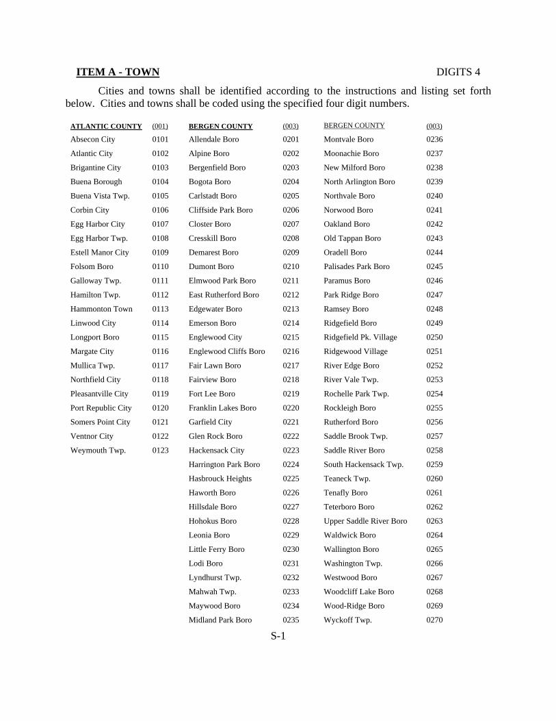
ITEM A - TOWN DIGITS 4
Cities and towns shall be identified according to the instructions and listing set forth below. Cities and towns shall be coded using the specified four digit numbers.
ATLANTIC COUNTY (001) BERGEN COUNTY (003) BERGEN COUNTY (003)
Absecon City 0101 Allendale Boro 0201 Montvale Boro 0236
Atlantic City 0102 Alpine Boro 0202 Moonachie Boro 0237
Brigantine City 0103 Bergenfield Boro 0203 New Milford Boro 0238
Buena Borough 0104 Bogota Boro 0204 North Arlington Boro 0239
Buena Vista Twp. 0105 Carlstadt Boro 0205 Northvale Boro 0240
Corbin City 0106 Cliffside Park Boro 0206 Norwood Boro 0241
Egg Harbor City 0107 Closter Boro 0207 Oakland Boro 0242
Egg Harbor Twp. 0108 Cresskill Boro 0208 Old Tappan Boro 0243
Estell Manor City 0109 Demarest Boro 0209 Oradell Boro 0244
Folsom Boro 0110 Dumont Boro 0210 Palisades Park Boro 0245
Galloway Twp. 0111 Elmwood Park Boro 0211 Paramus Boro 0246
Hamilton Twp. 0112 East Rutherford Boro 0212 Park Ridge Boro 0247
Hammonton Town 0113 Edgewater Boro 0213 Ramsey Boro 0248
Linwood City 0114 Emerson Boro 0214 Ridgefield Boro 0249
Longport Boro 0115 Englewood City 0215 Ridgefield Pk. Village 0250
Margate City 0116 Englewood Cliffs Boro 0216 Ridgewood Village 0251
Mullica Twp. 0117 Fair Lawn Boro 0217 River Edge Boro 0252
Northfield City 0118 Fairview Boro 0218 River Vale Twp. 0253
Pleasantville City 0119 Fort Lee Boro 0219 Rochelle Park Twp. 0254
Port Republic City 0120 Franklin Lakes Boro 0220 Rockleigh Boro 0255
Somers Point City 0121 Garfield City 0221 Rutherford Boro 0256
Ventnor City 0122 Glen Rock Boro 0222 Saddle Brook Twp. 0257
Weymouth Twp. 0123 Hackensack City 0223 Saddle River Boro 0258
Harrington Park Boro 0224 South Hackensack Twp. 0259
Hasbrouck Heights 0225 Teaneck Twp. 0260
Haworth Boro 0226 Tenafly Boro 0261
Hillsdale Boro 0227 Teterboro Boro 0262
Hohokus Boro 0228 Upper Saddle River Boro 0263
Leonia Boro 0229 Waldwick Boro 0264
Little Ferry Boro 0230 Wallington Boro 0265
Lodi Boro 0231 Washington Twp. 0266
Lyndhurst Twp. 0232 Westwood Boro 0267
Mahwah Twp. 0233 Woodcliff Lake Boro 0268
Maywood Boro 0234 Wood-Ridge Boro 0269
Midland Park Boro 0235 Wyckoff Twp. 0270
S-1

ITEM A - TOWN (CONTINUED) DIGITS 4
BURLINGTON COUNTY (005) BURLINGTON COUNTY (005) CAMDEN COUNTY (007)
Bass River Twp. 0301 Washington Twp. 0336 Audubon Boro 0401
Beverly City 0302 Westampton Twp. 0337 Audubon Park Boro 0402
Bordentown City 0303 Willingboro Twp. 0338 Barrington Boro 0403
Bordentown Twp. 0304 Woodland Twp. 0339 Bellmawr Boro 0404
Burlington City 0305 Wrightstown Boro 0340 Berlin Boro 0405
Burlington Twp. 0306 Berlin Twp. 0406
Chesterfield Twp. 0307 Brooklawn Boro 0407
Cinnaminson Twp. 0308 Camden City 0408
Delanco Twp. 0309 Cherry Hill Twp. 0409
Delran Twp. 0310 Chesilhurst Boro 0410
Eastampton Twp. 0311 Clementon Boro 0411
Edgewater Park Twp. 0312 Collingswood Boro 0412
Evesham Twp. 0313 Gibbsboro Boro 0413
Fieldsboro Boro 0314 Gloucester City 0414
Florence Twp. 0315 Gloucester Twp. 0415
Hainesport Twp. 0316 Haddon Twp. 0416
Lumberton Twp. 0317 Haddonfield Boro 0417
Mansfield Twp. 0318 Haddon Heights Boro 0418
Maple Shade Twp. 0319 Hi-Nella Boro 0419
Medford Twp. 0320 Laurel Springs Boro 0420
Medford Lakes Boro 0321 Lawnside Boro 0421
Moorestown Twp. 0322 Lindenwold Boro 0422
Mount Holly Twp. 0323 Magnolia Boro 0423
Mount Laurel Twp. 0324 Merchantville Boro 0424
New Hanover Twp. 0325 Mount Ephraim Boro 0425
North Hanover Twp. 0326 Oaklyn Boro 0426
Palymra Boro 0328 Pennsauken Twp. 0427
Pemberton Boro 0328 Pine Hill Boro 0428
Pemberton Twp. 0329 Pine Valley Boro 0429
Riverside Twp. 0330 Runnemede Boro 0430
Riverton Boro 0331 Somerdale Boro 0431
Shamong Twp. 0332 Stratford Boro 0432
Southampton Twp. 0333 Tavistock Boro 0433
Springfield Twp. 0334 Voorhees Twp. 0434
Tabernacle Twp. 0335 Waterford Twp. 0435
Winslow Twp. 0436
Woodlynne Boro 0437
S-2
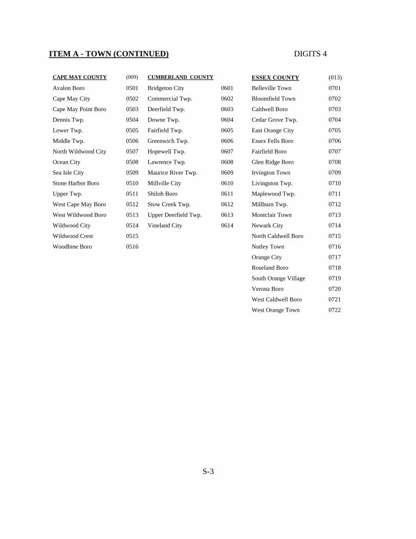
ITEM A - TOWN (CONTINUED) DIGITS 4
CAPE MAY COUNTY (009) CUMBERLAND COUNTY ESSEX COUNTY (013)
Avalon Boro 0501 Bridgeton City 0601 Belleville Town 0701
Cape May City 0502 Commercial Twp. 0602 Bloomfield Town 0702
Cape May Point Boro 0503 Deerfield Twp. 0603 Caldwell Boro 0703
Dennis Twp. 0504 Downe Twp. 0604 Cedar Grove Twp. 0704
Lower Twp. 0505 Fairfield Twp. 0605 East Orange City 0705
Middle Twp. 0506 Greenwich Twp. 0606 Essex Fells Boro 0706
North Wildwood City 0507 Hopewell Twp. 0607 Fairfield Boro 0707
Ocean City 0508 Lawrence Twp. 0608 Glen Ridge Boro 0708
Sea Isle City 0509 Maurice River Twp. 0609 Irvington Town 0709
Stone Harbor Boro 0510 Millville City 0610 Livingston Twp. 0710
Upper Twp. 0511 Shiloh Boro 0611 Maplewood Twp. 0711
West Cape May Boro 0512 Stow Creek Twp. 0612 Millburn Twp. 0712
West Wildwood Boro 0513 Upper Deerfield Twp. 0613 Montclair Town 0713
Wildwood City 0514 Vineland City 0614 Newark City 0714
Wildwood Crest 0515 North Caldwell Boro 0715
Woodbine Boro 0516 Nutley Town 0716
Orange City 0717
Roseland Boro 0718
South Orange Village 0719
Verona Boro 0720
West Caldwell Boro 0721
West Orange Town 0722
S-3

ITEM A - TOWN (CONTINUED) DIGITS 4
GLOUCESTER COUNTY (015) HUDSON COUNTY (017) HUNTERDON COUNTY (019)
Clayton Boro 0801 Bayonne City 0901 Alexandria Twp. 1001
Deptford Twp. 0802 East Newark Boro 0902 Bethlehem Twp. 1002
East Greenwich Twp. 0803 Guttenberg Town 0903 Bloomsbury Boro 1003
Elk Twp. 0804 Harrison Town 0904 Califon Boro 1004
Franklin Twp. 0805 Hoboken City 0905 Clinton Town 1005
Glassboro Boro 0806 Jersey City City 0906 Clinton Twp. 1006
Greenwich Twp. 0807 Kearny Town 0907 Delaware Twp. 1007
Harrison Twp. 0808 North Bergen Twp. 0908 East Amwell Twp. 1008
Logan Twp. 0809 Secaucus Town 0909 Flemington Boro 1009
Mantua Twp. 0810 Union City 0910 Franklin Twp. 1010
Monroe Twp. 0811 Weehawken Twp. 0911 Frenchtown Boro 1011
National Park Boro 0812 W. New York Town 0912 Glen Gardner Boro 1012
Newfield Boro 0813 Hampton Boro 1013
Paulsboro Boro 0814 High Bridge Boro 1014
Pitman Boro 0815 Holland Twp. 1015
South Harrison Twp. 0816 Kingwood Twp. 1016
Swedesboro Boro 0817 Lambertville City 1017
Washington Twp. 0818 Lebanon Boro 1018
Wenonah Boro 0819 Lebanon Twp. 1019
West Deptford Twp. 0820 Milford Boro 1020
Westville Boro 0821 Raritan Twp. 1021
Woodbury City 0822 Readington Twp. 1022
Woodbury Heights Boro 0823 Stockton Boro 1023
Wollwich Twp. 0824 Tewksbury Twp. 1024
Union Twp. 1025
West Amwell Twp. 1026
S-4

ITEM A - TOWN (CONTINUED) DIGITS 4
MERCER COUNTY (021) MIDDLESEX COUNTY (023) MONMOUTH COUNTY (025)
East Windsor Twp. 1101 Carteret Boro 1201 Allenhurst Boro 1301
Ewing Twp. 1102 Cranbury Twp. 1202 Allentown Boro 1302
Hamilton Twp. 1103 Dunellen Boro 1203 Asbury Park City 1303
Hightstown Boro 1104 East Brunswick Twp. 1204 Atlantic Highlands Boro 1304
Hopewell Boro 1105 Edison Twp. 1205 Avon By The Sea Boro 1305
Hopewell Twp. 1106 Helmetta Boro 1206 Belmar Boro 1306
Lawrence Twp. 1107 Highland Park Boro 1207 Bradley Beach Boro 1307
Pennington Boro 1108 Jamesburg Boro 1208 Brielle Boro 1308
Princeton Boro 1109 Old Bridge Twp. 1209 Colts Neck Twp. 1309
Princeton Twp. 1110 Metuchen Boro 1210 Deal Boro 1310
Trenton City 1111 Middlesex Boro 1211 Eatontown Boro 1311
Washington Twp. 1112 Milltown Boro 1212 Englishtown Boro 1312
West Windsor Twp. 1113 Monroe Twp. 1213 Fair Haven Boro 1313
New Brunswick City 1214 Famingdale Boro 1314
North Brunswick Twp. 1215 Freehold Boro 1315
Perth Amboy City 1216 Freehold Twp. 1316
Piscataway Twp. 1217 Highlands Boro 1317
Plainsboro Twp. 1218 Holmdel Twp. 1318
Sayreville Boro 1219 Howell Twp. 1319
South Amboy City 1220 Interlaken Boro 1320
South Brunswick Twp. 1221 Keansburg Boro 1321
South Plainfield Boro 1222 Keyport Boro 1322
South River Boro 1223 Little Silver Boro 1323
Spotswood Boro 1224 Loch Arbour Village 1324
Woodbridge Twp. 1225 Long Branch City 1325
Manalapan Twp. 1326
Manasquan Boro 1327
Marlboro Twp. 1328
Matawan Boro 1329
Aberdeen Twp. 1330
Middletown Twp. 1331
Millstone Twp. 1332
Monmouth Beach Boro 1333
S-5

ITEM A - TOWN (CONTINUED) DIGITS 4
MONMOUTH COUNTY (025) MORRIS COUNTY (027) MORRIS COUNTY (027)
Neptune Twp. 1334 Booton Town 1401 Rockaway Boro 1434
Neptune City Boro 1335 Boonton Twp. 1402 Rockaway Twp. 1435
Ocean Twp. 1337 Butler Boro 1403 Roxbury Twp. 1436
Oceanport Boro 1338 Chatham Boro 1404 Victory Gardens Boro 1437
Hazlet Twp. 1339 Chatham Twp. 1405 Washington Twp. 1438
Red Bank Boro 1340 Chester Boro 1406 Wharton Boro 1439
Roosevelt Boro 1341 Chester Twp. 1407
Rumson Boro 1342 Denville Twp. 1408
Sea Bright Boro 1343 Dover Town 1409
Sea Girt Boro 1344 East Hanover Twp. 1410
Shrewsbury Boro 1345 Florham Park Boro 1411
Shrewsbury Twp. 1346 Hanover Twp. 1412
Boro of Lake Como 1347 Harding Twp. 1413
Spring Lake Boro 1348 Jefferson Twp. 1414
Spring Lake Heights Bor. 1349 Kinnelon Boro 1415
Tinton Falls Boro 1336 Lincoln Park Boro 1416
Union Beach Boro 1350 Madison Boro 1417
Upper Freehold Twp. 1351 Mendham Boro 1418
Wall Twp. 1352 Mendham Twp. 1419
W. Long Branch Boro 1353 Mine Hill Twp. 1420
Montville Twp. 1421
Morris Twp. 1422
Morris Plains Boro 1423
Morristown Town 1424
Mountain Lakes Boro 1425
Mount Arlington Boro 1426
Mount Olive Twp. 1427
Netcong Boro 1428
Parsippany-Troy Hills Twp. 1429
Passaic Twp. 1430
Pequannock Twp. 1431
Randolph Twp. 1432
Riverdale Boro 1433
S-6

ITEM A - TOWN (CONTINUED) DIGITS 4
OCEAN COUNTY (029) PASSAIC COUNTY (031) SALEM COUNTY (033)
Barnegat Light Boro 1501 Bloomingdale Boro 1601 Alloway Twp. 1701
Bay Head Boro 1502 Clifton City 1602 Carney’s Point Twp. 1713
Beach Haven Boro 1503 Haledon Boro 1603 Elmer Boro 1702
Beachwood Boro 1504 Hawthorne Boro 1604 Elsinboro Twp. 1703
Berkeley Twp. 1505 Little Falls Twp. 1605 Lower Alloways Creek 1704
Brick Twp. 1506 North Haledon Boro 1606 Mannington Twp. 1705
Toms River Twp. 1507 Passaic City 1607 Oldmans Twp. 1706
Eagleswood Twp. 1508 Paterson City 1608 Penns Grove Boro 1707
Harvey Cedars Boro 1509 Pompton Lakes Boro 1609 Pennsville Twp. 1708
Island Heights Boro 1510 Prospect Park Boro 1610 Pilesgrove Twp. 1709
Jackson Twp. 1511 Ringwood Boro 1611 Pittsgrove Twp. 1710
Lacey Twp. 1512 Totowa Boro 1612 Quinton Twp. 1711
Lakehurst Boro 1513 Wanaque Boro 1613 Salem City 1712
Lakewood Twp. 1514 Wayne Twp. 1614 Upper Pittsgrove Twp. 1714
Lavalette Boro 1515 West Milford Twp. 1615 Woodstown Boro 1715
Little Egg Harbor Twp. 1516 West Paterson Boro 1616
Long Beach Twp. 1517
Manchester Twp. 1518
Mantaloking Boro 1519
Ocean Twp. 1520
Ocean Gate Boro 1521
Pine Beach Boro 1522
Plumstead Twp. 1523
Point Pleasant Boro 1524
Pt. Pleasant Beach Boro 1525
Seaside Heights Boro 1526
Seaside Park Boro 1527
Ship Bottom Boro 1528
South Toms River Boro 1529
Stafford Twp. 1530
Surf City Boro 1531
Tuckerton Boro 1532
Barnegat Twp. 1533
S-7

ITEM A - TOWN (CONTINUED) DIGITS 4
SOMEREST COUNTY (035) SUSSEX COUNTY (037) UNION COUNTY (039)
Bedminister Twp. 1801 Andover Boro 1901 Berkeley Heights Twp. 2001
Bernards Twp. 1802 Andover Twp. 1902 Clark Twp. 2002
Bernardsville Boro 1803 Branchville Boro 1903 Cranford Twp. 2003
Bound Brook Boro 1804 Byram Twp. 1904 Elizabeth City 2004
Brachburg Twp. 1805 Frankford Twp. 1905 Fanwood Boro 2005
Bridgewater Twp. 1806 Franklin Boro 1906 Garwood Boro 2006
Far Hills Boro 1807 Fredon Twp. 1907 Hillside Twp. 2007
Franklin Twp. 1808 Green Twp. 1908 Kenilworth Boro 2008
Green Brook Twp. 1809 Hamburg Boro 1909 Linden City 2009
Hillsborough Twp. 1810 Hampton Twp. 1910 Mountainside Boro 2010
Manville Boro 1811 Hardyston Twp. 1911 New Providence Boro 2011
Millstone Boro 1812 Hopatcong Boro 1912 Plainfield City 2012
Montgomery Twp. 1813 Lafayette Twp. 1913 Rahway City 2013
North Plainfield Boro 1814 Montague Twp. 1914 Roselle Boro 2014
Peapack-Gladstone Boro 1815 Newton Town 1915 Roselle Park Boro 2015
Raritan Boro 1816 Ogdensburg Boro 1916 Scotch Plains Twp. 2016
Rocky Hill Boro 1817 Sandyston Twp. 1917 Springfield Twp. 2017
Somerville Boro 1818 Sparta Twp. 1918 Summit City 2018
So. Bound Brook Boro 1819 Stanhope Boro 1919 Union Twp. 2019
Warren Twp. 1820 Stillwater Twp. 1920 Westfield Town 2020
Watchung Boro 1821 Sussex Boro 1921 Winfield Twp. 2021
Vernon Twp. 1922
Walpack Twp. 1923
Wantage Twp. 1924
S-8

ITEM A - TOWN (CONTINUED) DIGITS 4
WARREN COUNTY
Allamuchy Twp. 2101
Alpha Boro 2102
Belvidere Town 2103
Blairstown Twp. 2104
Franklin Twp. 2105
Frelinghuysen Twp. 2106
Greenwich Twp. 2107
Hacketstown Town 2108
Hardwick Twp. 2109
Harmony Twp. 2110
Hope Twp. 2111
Independence Twp. 2112
Knowlton Twp. 2133
Liberty Twp. 2114
Lopatcong Twp. 2115
Mansfield Twp. 2116
Oxford Twp. 2117
Pahaquarry Twp. 2118
Phillipsburg Town 2119
Pohatcong Twp. 2120
Washington Boro 2121
Washington Twp. 2122
White Twp. 2123
S-9
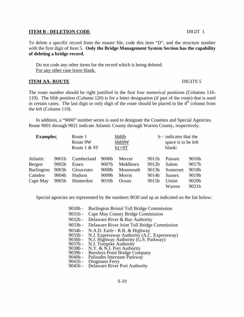
ITEM B - DELETION CODE DIGIT 1 To delete a specific record from the master file, code this item “D”, and the structure number with the first digit of Item 5. Only the Bridge Management System Section has the capability of deleting a bridge record. Do not code any other items for the record which is being deleted. For any other case leave blank. ITEM AA- ROUTE DIGITS 5
The route number should be right justified in the first four numerical positions (Columns 116-119). The fifth position (Column 120) is for a letter designation (if part of the route) that is used in certain cases. The last digit or only digit of the route should be placed in the 4th column from the left (Column 119). In addition, a “9000” number series is used to designate the Counties and Special Agencies. Route 9001 through 9021 indicate Atlantic County through Warren County, respectively. Examples: Route 1 bbblb b - indicates that the Route 9W bbb9W space is to be left Route 1 & 9T b1+9T blank\ Atlantic 9001b Cumberland 9006b Mercer 9011b Passaic 9016b Bergen 9002b Essex 9007b Middlesex 9012b Salem 9017b Burlington 9003b Gloucester 9008b Monmouth 9013b Somerset 9018b Camden 9004b Hudson 9009b Morris 9014b Sussex 9019b Cape May 9005b Hunterdon 9010b Ocean 9015b Union 9020b Warren 9021b
Special agencies are represented by the numbers 9030 and up as indicated on the list below:
9030b - Burlington Bristol Toll Bridge Commission 9031b - Cape May County Bridge Commission 9032b - Delaware River & Bay Authority 9033b - Delaware River Joint Toll Bridge Commission 9034b - N.A.D. Earle - R.R. & Highway 9035b - N.J. Expressway Authority (A.C. Expressway) 9036b - N.J. Highway Authority (G.S. Parkway) 9037b - N.J. Turnpike Authority 9038b - N.Y. & N.J. Port Authority 9039b - Beesleys Point Bridge Company 9040b - Palisades Interstate Parkway 9041b - Dingmans Ferry 9045b - Delaware River Port Authority
S-10
ITEM AA- ROUTE (CONTINUED)
9046b - Somerset County Park Commission 9047b - Margate Bridge Company 9048b - Essex County Park Commission 9049b - N.J. Sports & Exposition Authority 9050b U.S. Dept. of Int. Fish and Wildlife Services 9051b - U.S. Air Force 9052b - U.S. Army 9053b - Bergen County Park Commission 9054b - U.S. National Park Service
A “9100” number series is used to designate municipality owned bridge in various counties. The first two digits of Item AA - Route shall be coded “91”; the third and fourth digits shall be coded with the appropriate county code used in 9000 number series; and the fifth digit shall be left blank. Examples: Route 9101 Code 9101b for Municipality owned bridges in
Atlantic County Route 9121 Code 9121b for Municipality owned bridges in
Warren County PRIVATELY OWNED BRIDGES The route number for privately owned bridges shall be designated according to the following: Private Structures across Interstate, U.S., State or Special Agency Routes: These
structures shall be coded according to the Route Intersected.
Private Structures across Railroads: These structures shall be coded according to the railroad line the structure crosses (see route designation).
Private Structure across other features: All these structures shall be coded under route "9200".
OTHER AGENCIES A. State D&R Canal 3000b - D&R Canal (Main) 3001b - D&R Canal (Feeder)
S-11

OTHER AGENCIES (CONTINUED)
N.J. Division of Fish, Game & Wildlife Services
3200b - Cumberland County STATE PARKS 3305b - Stevens State Park 3310b - Ringwood State Park 3407b - High Point State Park 3461b - Stokes State Forest 3462b - Wawayanda State Park 3481b - Lebanon State Forest 3485b - Wharton State Park 3486b - Spruce Run Recreation Area 3487b - Round Valley Recreation Area NEW JERSEY TRANSIT R.R. Routes
Rail System Name
Former Owner
USRA Line Code
4001 Pascack Valley Line Erie Lackawanna 6152 & 6164 4002 Bergen County Line Erie Lackawanna 6102 4003 Main Line Erie Lackawanna 6151 4004 Boonton Line
(M.P. 2.70 to 34.10) Erie Lackawanna 6101
4005 Morristown Line (M.P. 34.10 to 47.90 Morristown Line (M.P. 00.00 to 36.30)
Erie Lackawanna 6101
4006 Harrison Branch Erie Lackawanna 6169 4007 Montclair Branch Erie Lackawanna 6842 4009 Gladstone Branch Erie Lackawanna 6841 4011 North Jersey Coast Line Penn Central Perth Amboy &
Woodbridge Branch Central RR, Perth Amboy Branch N.Y. & Long Branch Railroad
0201
4012 Matawan - Freehold Line Central RR of NJ 0216 4013 Freehold Branch Penn Central 1427 4014 Southern Division Central RR of NJ 0216 4015 Princeton Branch United NJ RR & Canal Co. 0215 4050 Atlantic City Line Penn Reading Seashore Line 9901 4051 Cape May Line Penn Reading Seashore Line 9903 4052 Ocean City Branch Penn Reading Seashore 9906 4056 Millville Branch Penn Reading Seashore Line 9909 4057 Pemberton Branch Penn Central
S-12

OTHER AGENCIES (CONTINUED) A “500” number series is used to designate railroad carrying bridges on state owned routes. Example: Lehigh Valley Railroad over Route 82 Code Item “A” as 5082b B. OTHERS AMTRAK A “6000” number series is used to designate the orphan highway bridges over AMTRAK. Route 6001b through 6021b indicate Atlantic County through Warren County, respectively. CONRAIL A “6100” number series is used to designate the orphan highway bridges over Conrail, CSX and Norfolk Southern. Route 6101b through 6121b indicate Atlantic County through Warren County, respectively. OTHER RAILROAD LINES NATIONAL PARK 6150 to 6157b Private Railroads 3505b - Delaware Water Gap 6158 to 6199 Miscellaneous National Recreation Area ITEM AB - NAME OF STRUCTURE DIGITS 37 Write the name of the structure indicating the route carried and the feature below in the paces provided. No numerical coding of this item is necessary; use narrative description. Example: Route 440 over Smith Street County Route 523 over I-287 7th Street Pedestrian Bridge
S-13

ITEM AC - NON-INVENTORY FEATURE DIGIT 2 This item should only be coded when there is only one set of Bridge Inventory master Input forms for the structure and one of the features intersected in Waterway, Railroad or Pedestrian overpass. Code WW for roadway and/or railroad over waterway Code RR for roadway and/or railroad over railroad Code RW for roadway over railroad and waterway Code PD for a pedestrian overpass or underpass Note: Leave this item Blank if two or more sets of Bridge Inventory Master Input Forms are coded. ITEM AD - ADMINISTRATIVE JURISDICTION DIGIT 1 NON-INVENTORY FEATURE This item should only be coded when there is only one set of Bridge Inventory Master Input forms for the structure and one of the features intersected is Waterway, Railroad or Pedestrian overpass. Code a single digit number, using the coding designations shown below, to classify the jurisdiction of the non-inventory feature under the structure. 1. State 2. Federal domain 3. Toll 4. Other existing (which includes county and local jurisdiction) 5. Not assigned 6. New Jersey Transit owned 7. Conrail owned (CSX and Norfolk Southern Joint Assets) 8. Amtrak owned 9. Owned by private railroad A. Norfolk Southern RR owned B. CSX RR owned All waterway in New Jersey should be coded 1.
NOTE: Leave this item “Blank” if two or more sets of Bridge Inventory Master Input forms are coded.
S-14

ITEM AE - ALTERNATE AGENCY DIGITS 5 If the structure is owned by more than one agency (dual ownership), another agency maintains an interest in the structure (example--county bridge over NJTPK), or if the structure number in Item 8 does not adequately describe the owner’s structure number, code a four digit number to represent the agency which is not conducting the present inspection (except in the last case) based on the codes for Item AA. The last (fifth) digit will represent the relationship of the agency identified in this item to the agency identified in Item AA as follows:
Co-owner of bridge - 1 Interested agency - 2 Same owner as Item AA - b (blank) Examples: Coding A. Structure owned by Bergen and Passaic 90161 Counties with Item AA coded “9002”. B. Structure owned by Middlesex County 90372 that carries traffic over the New Jersey Turnpike with Item AA coded “9012”. This Item would represent an “interested agency” in this example. C. Structure owned by Mercer County with Item AA 9011b Blank
coded “9011” and the structure number coded in Item 8 does not adequately represent the County’s structure number.
ITEM AF - ALTERNATE STRUCTURE NUMBER DIGITS 7 Code the structure number (left justified) assigned by the agency indicated in Item AE “Alternate Agency”. Leave blank if not applicable. ITEM AG - TYPE OF BRIDGE RAILING DIGITS 2 The type of bridge railing should be coded according to the code listed below:
Code
Railroad Description
Blank None 01 = 1 Rail Steel on top of concrete parapet 02 = 1 Rail Aluminum on top of concrete parapet 03 = 2 Rail Steel on top of concrete parapet 04 = 2 Rail Aluminum on top of concrete parapet 05 = 3 Rail Steel 06 = 3 Rail Aluminum
S-15

ITEM AG - TYPE OF BRIDGE RAILING (CONTINUED)
Code
Railroad Description
07 = Concrete Balustrade 08 = Solid Wall (Concrete)—Includes NJ Barrier Type 09 = Solid Metal (includes Thru-Girder Type) 10 = Concrete - Metal Combination 11 = Concrete with Wooden Top Rail 12 = Concrete with Wooden Top Rail and Wood Bumper Rail 13 = All Wood Railing 14 = Pedestrian Railing (to be used adjacent to a sidewalk
when Highway Traffic is separated from Pedestrian Traffic)
15 = Caged Pedestrian Bridge Railing—Pedestrian Bridges 16 = More than one type of Railing 17 = Encased Thru-Girder type 18 = None of the types above 19 = Approach roadway guide rail carried across the culvert
If a supplementary W-beam guide rail has been added in front of the original bridge railing, modify the previous codes as follows:
Add “20” to previous code if the W-beam railing is mounted on the deck, sidewalk, safetywalk or curb. Add “40” to previous code if the W-beam railing is mounted on the original bridge railing or superstructure.
ITEM AH - HEIGHT OF BRIDGE RAILING DIGITS 3 Code the height of the bridge railing to the nearest hundredth of a foot in the space provided. The height of the bridge railings that are mounted atop sidewalks should be measured from the top of the sidewalk. For bridge railing systems that are mounted with the face flush with the sidewalk, brushburb or curb (typically bridge mounted steel w-beam types), measure the height from the top of the deck slab. Examples: 3’ - 6” = 350 4’ - 0” = 400 Leave blank if approach roadway guide rail is carried across the culvert.
S-16
ITEM AI - SPEED POSTING DIGITS 2
Code the posted speed limit for the bridge in miles per hour (only where it has been reduced from the rest of the roadway). Yellow caution speed limit signs qualify as a speed posting. Where no speed restrictions are found, leave this item blank.
NOTE: Item 41 will not be coded “R” due to the speed posting unless the speed has been reduced due to a load capacity restriction.
ITEM AJ - TYPE OF SLOPE PROTECTION DIGITS 2 Code a 2 digit number for the type of slope protection under the structure, according to the following codes:
Code Type of Slope Protection Blank = None 01 = Concrete Block 02 = Masonry (Brick, Cobblestone, etc.) 03 = Concrete Slab 04 = Sand Bag (Including Concrete Filled Sand Bags) 05 = Stone Rip-Rap 06 = Combination of Material 07 = Bituminous Concrete 08 = Timber Bulkhead 09 = Steel Sheet Pile Bulkhead
ITEM AK - TYPE OF ABUTMENT DIGITS 2
Code a 2 digit number to classify the type of abutments found under the structure. The codes are listed below:
Code Type of Abutment Blank = None (as in a Rigid Frame, Box Culvert, etc.) 01 = Stub (Breastwall Height Less Than 4’). 02 = Semi-stub (Breastwall height Greater than 4’). 03 = Full Height 04 = Counterfort 05 = Timber - Bulkhead 06 = Integral 07 = Masonry (Brick, Fieldstone, etc.). 08 = Open or Spill Through Type 09 = Gravity 10 = Combination
S-17

ITEM AK - TYPE OF ABUTMENT (CONTINUED) If one of the abutments is on timber piles add “10” to the appropriate code, add “30” for one abutment on steel piles and add “50” for one abutment on concrete piles. Examples: Full Height abutment on Timber Piles Code 13 Full Height abutment on Steel Piles Code 33 Full Height abutment on Concrete Piles Code 53 If both abutments are on Timber piles add “20” to the appropriate code, add “40” for abutments on steel piles, and add “60” for abutments on concrete piles. Examples: Full Height abutments on Timber Piles Code 23 Full Height abutments on Steel Piles Code 43 Full Height abutments on Concrete Piles Code 63 ITEM AL - TYPE OF PIER DIGITS 2 Code a 2 digit number to classify the type of pier. Use the codes listed below:
Code Type of Pier Blank = None (1 Span Bridge) 01 = Hammerhead Piers 02 = Solid Wall Pier 03 = Concrete Pile Bents 04 = Individual Column (1 Column Per Beam) 05 = Timber Pile Bent 06 = Concrete Column Bent 07 = Steel Bent 08 = Concrete Pier Cap on Steel Piles 09 = Concrete Pier Cap on Timber Piles 10 = Combination
If one or more piers are on Timber piles and “10” to the appropriate code, add “30” for one pier on Steel piles, and add “50” for one pier on concrete piles. Examples: One or more Hammerhead Piers on Timber Piles Code 11 One or more Hammerhead Piers on Steel Piles Code 31 One or more Hammerhead Piers on Concrete Piles Code 51
S-18

ITEM AL - TYPE OF PIER (CONTINUED) If all piers are on Timber piles add “20” to the appropriate code, add “40” for piers on Steel piles, and add “60” for piers on concrete piles. Examples: All Concrete Column bents on Timber Piles Code 26 All Concrete Column bents on Steel Piles Code 46 All Concrete Column bents on Concrete Piles Code 66 ITEM AM - DEPTH OF FILL OVER STRUCTURE DIGITS 3 Code the depth of fill over the structure to the nearest tenth of a foot. This item should generally be coded only if Item 43B (Type of design and/or of construction) is coded 01, 05, 06, 07, 11, 12, 19 or 22. Example: 0’-0” = 000 8’-0” = 080 7’-6” = 075 12’-4” = 123 ITEM AN - PLANS AVAILABILITY DIGIT 1 If plans are readily available, code “1”; if plans are not available, code “0”. ITEM AO - UTILITY DIGITS 4 From the list provided, code the letter that represents the utility supported by the structure. Code the right most position first. If the structure carries more than one utility, multiple codings should be made. If there are no utilities, leave the item blank.
Code Type of Utility
E Electrical Conduit G Gas Main S Sanitary Sewer T Telephone Conduit W Water Main F Fiber Optic Z Other
S-19
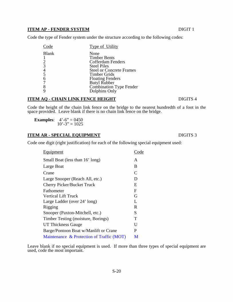
ITEM AP - FENDER SYSTEM DIGIT 1 Code the type of Fender system under the structure according to the following codes:
Code Type of Utility Blank None 1 Timber Bents 2 Cofferdam Fenders 3 Steel Piles 4 Steel or Concrete Frames 5 Timber Grids 6 Floating Fenders 7 Butyl Rubber 8 Combination Type Fender 9 Dolphins Only
ITEM AQ - CHAIN LINK FENCE HEIGHT DIGITS 4 Code the height of the chain link fence on the bridge to the nearest hundredth of a foot in the space provided. Leave blank if there is no chain link fence on the bridge. Examples: 4’-6” = 0450 10’-3” = 1025 ITEM AR - SPECIAL EQUIPMENT DIGITS 3 Code one digit (right justification) for each of the following special equipment used:
Equipment Code
Small Boat (less than 16’ long) A Large Boat B Crane C Large Snooper (Reach All, etc.) D Cherry Picker/Bucket Truck E Fathometer F Vertical Lift Truck G Large Ladder (over 24’ long) L Rigging R Snooper (Paxton-Mitchell, etc.) S Timber Testing (moisture, Borings) T UT Thickness Gauge U Barge/Pontoon Boat w/Manlift or Crane P Maintenance & Protection of Traffic (MOT) M
Leave blank if no special equipment is used. If more than three types of special equipment are used, code the most important.
S-20
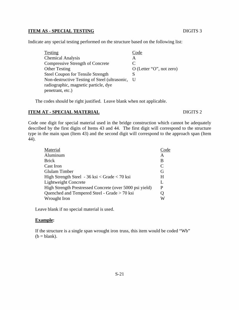
ITEM AS - SPECIAL TESTING DIGITS 3 Indicate any special testing performed on the structure based on the following list:
Testing Code Chemical Analysis A Compressive Strength of Concrete C Other Testing O (Letter “O”, not zero) Steel Coupon for Tensile Strength S Non-destructive Testing of Steel (ultrasonic, radiographic, magnetic particle, dye penetrant, etc.)
U
The codes should be right justified. Leave blank when not applicable. ITEM AT - SPECIAL MATERIAL DIGITS 2 Code one digit for special material used in the bridge construction which cannot be adequately described by the first digits of Items 43 and 44. The first digit will correspond to the structure type in the main span (Item 43) and the second digit will correspond to the approach span (Item 44).
Material Code Aluminum A Brick B Cast Iron C Glulam Timber G High Strength Steel - 36 ksi < Grade < 70 ksi H Lightweight Concrete L High Strength Prestressed Concrete (over 5000 psi yield) P Quenched and Tempered Steel - Grade > 70 ksi Q Wrought Iron W
Leave blank if no special material is used. Example: If the structure is a single span wrought iron truss, this item would be coded “Wb” (b = blank).
S-21
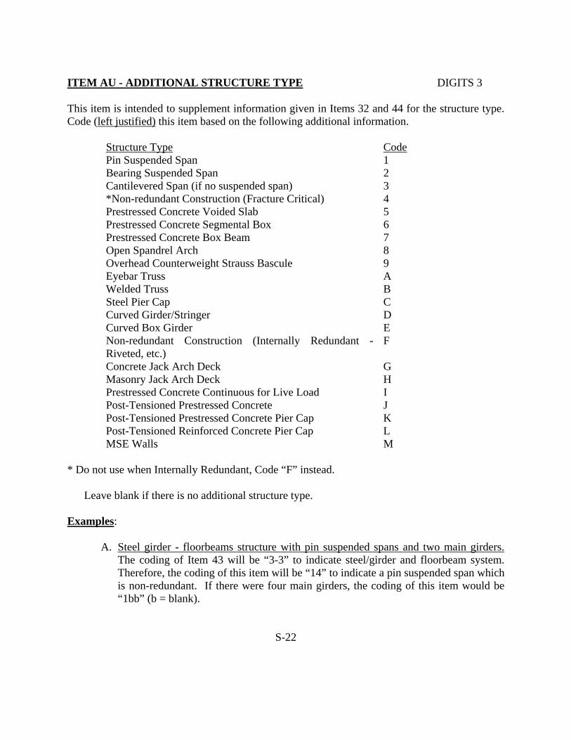
ITEM AU - ADDITIONAL STRUCTURE TYPE DIGITS 3 This item is intended to supplement information given in Items 32 and 44 for the structure type. Code (left justified) this item based on the following additional information.
Structure Type Code Pin Suspended Span 1 Bearing Suspended Span 2 Cantilevered Span (if no suspended span) 3 *Non-redundant Construction (Fracture Critical) 4 Prestressed Concrete Voided Slab 5 Prestressed Concrete Segmental Box 6 Prestressed Concrete Box Beam 7 Open Spandrel Arch 8 Overhead Counterweight Strauss Bascule 9 Eyebar Truss A Welded Truss B Steel Pier Cap C Curved Girder/Stringer D Curved Box Girder E Non-redundant Construction (Internally Redundant - Riveted, etc.)
F
Concrete Jack Arch Deck G Masonry Jack Arch Deck H Prestressed Concrete Continuous for Live Load I Post-Tensioned Prestressed Concrete J Post-Tensioned Prestressed Concrete Pier Cap K Post-Tensioned Reinforced Concrete Pier Cap L MSE Walls M
* Do not use when Internally Redundant, Code “F” instead. Leave blank if there is no additional structure type. Examples:
A. Steel girder - floorbeams structure with pin suspended spans and two main girders. The coding of Item 43 will be “3-3” to indicate steel/girder and floorbeam system. Therefore, the coding of this item will be “14” to indicate a pin suspended span which is non-redundant. If there were four main girders, the coding of this item would be “1bb” (b = blank).
S-22

ITEM AU - ADDITIONAL STRUCTURE TYPE (CONTINUED) Examples: B. Two span continuous curved steel stringer structure. The coding of Item 43 will be
“402” to indicate continuous steel stringer. Therefore, the coding of this item will be “Dbb”.
NOTE: When the following additional structure types are present, they should always
be coded in the available space: “1”-Pin Suspended Span, “4” - Non Redundant Construction (Fracture Critical), “D”-Curved Girder/Stringer, “E”-Curved Box Girder or “I”-Prestressed Concrete Continuous for Live Load.
ITEM AV - WIDENED STRUCTURE TYPE DIGITS 6 Code six digits to identify the structure type that has been widened with a type that differs from the type of original construction. The first three digits will refer to the first widening and the second three digits will refer to any subsequent widening. This item will be coded using the same codes as specified for Item 43. Leave blank if there is no widening type. Examples: A. A masonry arch bridge is first widened with steel stringer and then at a later date
widened with a concrete slab. The coding for this item would be “302101”. Item 43 would be coded “811” to indicate the original structure type.
B. If the above arch bridge was only widened with steel stringers, this Item would be coded “302bbb” (b = blank).
ITEM AW - DATE OF MECHANICAL - ELECTRICAL DIGITS 4 INSPECTION Code the month and year of the most recent Mechanical-Electrical inspection of the movable structure as follows: Mechanical-Electrical Inspection Date MM YY Leave blank if not applicable.
S-23

ITEM AX - DATE OF DECK CONDITION SURVEY DIGITS 4 Code the month and year of the most recent Deck Condition Survey of the structure as follows: Deck Condition Survey Date (DCS) MM YY Leave blank if not applicable. Also, this item should be blanked out once the deck repairs are completed or the DCS is more than 10 years old. ITEM AY - DATE OF SPECIAL TESTING DIGITS 4 Code the month and year of the most recent special testing of the structure that was performed as follows: Special Testing Date MM YY Leave blank if no applicable. The coding of this item must be consistent with the coding of Item AS - Special Testing. ITEM AZ - FATIGUE DETAIL LOCATIONS DIGITS 12 Code detail that are perceived as possible locations of future fatigue damage based on the following (left justified): Part A - The first two digits will correspond to the type of fatigue detail being described based
on the following codes.
01 - E’ cover plate detail 09 - Slot weld 02 - E cover plate detail 10 - Horizontal web stiffener 03 - Other E detail 11 - Distortion at small gap detail 04 - D detail 12 - Coped flange 05 - Field weld repair 13 - Blocked flange 06 - Tack weld 14 - Field welded splice 07 - Plug weld 08 - Backing bars 20 - Other detail
S-24

Part B - The last two digits will correspond to the member with the detail that is being described in the first two digits according to the following codes:
01 - Stringer 08 - Truss Compression Member 02 - Floorbeam 09 - Truss Tension Member 03 - I-Girder 10 - Hanger 04 - Box Girder 11 - Pier Cap 05 - Diaphragm 12 - Pier Column 06 - Cross Bracing 07 - Lateral Bracing 20 - Other location
If the member is non-redundant (fracture critical), add 20 to the above Part B codes. The first field should be coded for the most probable and the third field for the least probable locations of future fatigue damage. Fields which are not utilized should be left blank.
Examples: A. If the structure is a rolled multi-stringer bridge with cover plates (stringer flange
over 0.8" thick), this item would be coded "0101". B. If the structure has a steel box beam pier cap with backup bars at the groove welds
and is supported be a concrete column at each end (non-redundant), this item would be coded "0831".
C. If the structure has riveted plate girders where tack welds were used to hold the plates together during riveting and were not ground-off afterwards, this item would be coded "0603".
D. If a structure has all of the details of examples A, B, and C, the three fields of this item would be coded "0101", "0831" and "0603" to indicate the three locations of concern for possible fatigue damage.
S-25

ITEM BA - APPROACH ROADWAY CONDITION DIGIT 1 For this item, give the rating in relation to the effect of the approach roadway on the use of the bridge. This item should be coded based on settlement, spalls or any other defects and deterioration. Use the following table as an aid in coding this item: 9 Excellent Condition - new condition 8 Very Good Condition - no defects 7 Good Condition - minor defects such as cracking of approach roadway, small spalls in
approach roadway, minor settlements (less than 1”) or minor collision damage to guide rails.
6 Satisfactory Condition - more significant defects such as large spalls, severe settlements (1” to 2”) or major collision damage to guide rails. Moderate amounts of slope embankment erosion.
5 Fair Condition - defects requiring minor rehabilitation such as approach slabs pushing against abutment, settlements (over 2”) causing significant impact on the bridge, or large amounts of approach embankment erosion.
4 Poor Condition - defects requiring major rehabilitation such as buckling approach slabs,
undermining of approach shoulders due to erosion or approach slabs causing movement of abutment.
3 Serious Condition - defects requiring immediate repair or rehabilitation such as severe
undermining or washout of approach shoulders & loss of an approach guiderail section.
ITEM BB- ORPHAN BRIDGE DESIGNATION DIGIT 1
If the structure is an orphan bridge code "Y".
Leave blank if structure is not an orphan bridge (Do not blank out when originally coded "Y". Advice could be obtained from the Railroad Section of Structural Evaluation).
S-26

ITEM BC - USRA LINE CODE DIGITS 4 Code the USRA line code listed under Item AA (Railroad Route listing Page RA-2) for Railroad Bridges.
Example:
USRA Line Code 6152 - Code 6152
For New Jersey Transit USRA Line Codes, refer to page RA-1. For other rail lines not already coded, see Railroad Coding Instructions or advise Structural Evaluation.
ITEM BD - RAILROAD TRACKS ON AND UNDER THE STRUCTURE DIGITS 4
Code the number of the through tracks being carried be the structure as a 2- digit number. Also, code the total number of through tracks being crossed over by the structure as a 2-digit number. This item will be a 4-digit field consisting of two sub-fields with leading zeros in each of the sub-fields.
Example: 2 Tracks On, 1 Track Under Code 0201 2 Highway Lanes On, 2 Tracks Under Code 0002
ITEM BE - RAILROAD MILEPOST
Code this item according to the Railroad Milepost of the Railroad line as designated in Item 6.
If the structure is a railroad carrying bridge, code Railroad Milepost according to the railroad line designated in Item 7.
S-27

ITEM BF - REMARKS ON ITEM 58 (DECK) DIGITS 5 From the list provided, code the letter and/or digit that represents the corresponding defect. In the event of multiple defects, code those that are judged to be of a more serious nature to the integrity of the deck in the order of severity. Code the right most position first. If no defects are found, leave the item blank.
Code
Defects
A Medium to wide cracks B Severe scaling C Less than 2% spalls D Less than 5% spalls E More than 5% spalls F Holes in the deck G Det. timber planks H Det. asphalt overlay I Det. steel flooring J Det. expansion joint K Det. railings L Det. sidewalks M Deteriorated curbs N Det. deck joints O Joint leakage P Deck seepage Q Leakage w/efflorescence R Spalled under deck S Exposed rebars T Asphalt patched spalls U Med/Wide cracks under deck V Clogged scuppers W Det. parapet/balustrade Y Med. to heavy scaling Z Other defects 1 *1-19% contamination 2 *20-40% contamination 3 *41-60% contamination 4 *Over 60% contamination
* If a Deck Condition Survey was not done base the code on a visual inspection of the top and underside of the deck.
S-28

ITEM BG - REMARKS ON ITEM 59 (SUPERSTRUCTURE) DIGITS 3
From the list provided, code the letter and/or the digit that represents the corresponding defect. In the event of multiple defects, code those that are judged to be of a more serious nature to the integrity of the superstructure in the order to severity. Code the right most position first. If no defects are found, leave the item blank.
Code
Defects
A Mod/severe rusting B Collision damage C Loss of section D Encasement deterioration E Heavy spalling F *Wear in gear teeth G *Inadequate lubrication H *Improper pivot fit I *Pivot wear, cracks J *Improper track fit K *Track wear, cracks L *Roller or shaft wear M *Deter. counterweight N *Misaligned shaft O *Trunnion bearing deterioration P *Improper lift fit Q *Misalignm’t cables R *Misalignm’t sheaves S *Cracks in sheaves T Excess. expanded rocker U Excess. contracted rocker V Exposed strands W Weathered timber stringer Z Other 1 Collision scrapes 2 Severe collision damage 3 Spot rusting 4 Rusted bearings 5 Fatigue cracks 6 Broken prestress strands 7 Cracked prestressed members 8 Spalled underdeck 9 Leakage with efflorescence
* For Movable Bridges Only.
S-29
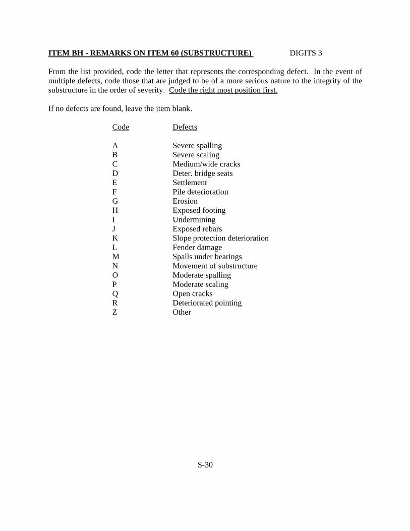
ITEM BH - REMARKS ON ITEM 60 (SUBSTRUCTURE) DIGITS 3 From the list provided, code the letter that represents the corresponding defect. In the event of multiple defects, code those that are judged to be of a more serious nature to the integrity of the substructure in the order of severity. Code the right most position first. If no defects are found, leave the item blank.
Code
Defects
A Severe spalling B Severe scaling C Medium/wide cracks D Deter. bridge seats E Settlement F Pile deterioration G Erosion H Exposed footing I Undermining J Exposed rebars K Slope protection deterioration L Fender damage M Spalls under bearings N Movement of substructure O Moderate spalling P Moderate scaling Q Open cracks R Deteriorated pointing Z Other
S-30

ITEM BI - REMARKS ON ITEM 61 (CHANNEL AND DIGIT 1 CHANNEL PROTECTION)
From the list provided, code the letter that represents the corresponding defect. In the event of multiple defects, code the defect that is judged to be of a more serious nature to the integrity of the structure. If no defects are found, leave the item blank.
Code
Defects
A Minor scour B Minor sedimentation and/or minor debris C Restricted flow due to sand bars, debris,
vegetation growth D Minor undermining is present F Debris accumulation on bridge seats due
to high water flow G Inadequate waterway opening H Damage to rip-rap/sheet piling I Heavy sedimentation J Heavy Scour K Heavy Scour with undermining L Embankment aggradation M Embankment degradation Z Other
ITEM BJ - REMARKS ON ITEM 62 (CULVERT) DIGIT 1 From the list provided, code the letter that represents the corresponding defect. In the event of multiple defects, code the defect that is judged to be of a more serious nature to the integrity of the structure. If no defects are found, leave the item blank.
Code Defects
A Light scaling, water stains, fine cracks B Small to large spalls without exposed rebars C Medium cracks and/or medium scaling D Small to large spalls with exposed rebars E Severe scaling, wide cracks F Water seepage through construction joints G Differential settlement H Collapsed wingwalls I Settlement of roadway due to loss of fill J Undermined floor slab Z Other
S-31

ITEM BK - PERCENT OVERSTRESS DIGITS 2 If the operating ratings are below the legal loads, compute percent overstress for the critical live load. Code a 2 digit number in the space provided.
Example: 6% overstress code 06.
If there is no overstress, do not code 00; leave this Item blank. This does not apply to prestressed concrete members with overstressing in the precompressed tensile zone.
Example: of overstress calculation:
Dead Load Stress FS (D) = 19.23 ksi Superimposed Dead Load Stress FS (SDL) = 1.04 ksi Stress due to 36 ton HS-20 Rating Vehicle FS (LL+I) = 7.52 ksi FS (TOTAL) = 27.79 ksi The allowable operating rating stress is 27.00 ksi
Overstress = 27.79/27.00-1) 100% = 2.9% ITEM BL - DISCRETIONARY FUNDS DIGITS 1 This item is for State in-house use only and the listings of specific bridges for coding will be provided by the Bridge Management System Section to Structural Evaluation.
Code 1 for "Funded" Code 2 for "Nominated for Funding" Code 3 for "Nominated, not Funded"
ITEM BM - FEDERAL JOB NUMBER DIGITS 12
Code the federal job number under which the bridge is inspected in the 10 positions from left. The last two positions should be filled in if the bridge is inspected under a modification of the original agreement.
Example: Job #BR-NBIS 008 Code as BRbNBIS008bb (b=blank) Job #BR-Z-NBIS 084 Code as BRZNBIS084bb (b=blank) Job #BR-Z-NBIS 084 Code as BRZNBIS08402
Contract Modification #2
S-32
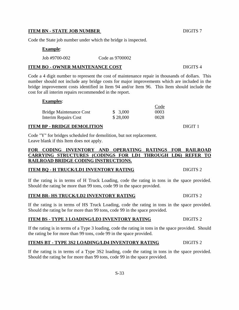
ITEM BN - STATE JOB NUMBER DIGITS 7 Code the State job number under which the bridge is inspected.
Example:
Job #9700-002 Code as 9700002 ITEM BO - OWNER MAINTENANCE COST DIGITS 4 Code a 4 digit number to represent the cost of maintenance repair in thousands of dollars. This number should not include any bridge costs for major improvements which are included in the bridge improvement costs identified in Item 94 and/or Item 96. This Item should include the cost for all interim repairs recommended in the report. Examples:
Code Bridge Maintenance Cost $ 3,000 0003
Interim Repairs Cost $ 28,000 0028 ITEM BP - BRIDGE DEMOLITION DIGIT 1 Code "Y" for bridges scheduled for demolition, but not replacement. Leave blank if this Item does not apply. FOR CODING INVENTORY AND OPERATING RATINGS FOR RAILROAD CARRYING STRUCTURES (CODINGS FOR LD1 THROUGH LD6) REFER TO RAILROAD BRIDGE CODING INSTRUCTIONS. ITEM BQ - H TRUCK/LD1 INVENTORY RATING DIGITS 2 If the rating is in terms of H Truck Loading, code the rating in tons in the space provided. Should the rating be more than 99 tons, code 99 in the space provided. ITEM BR- HS TRUCK/LD2 INVENTORY RATING DIGITS 2 If the rating is in terms of HS Truck Loading, code the rating in tons in the space provided. Should the rating be for more than 99 tons, code 99 in the space provided. ITEM BS - TYPE 3 LOADING/LD3 INVENTORY RATING DIGITS 2 If the rating is in terms of a Type 3 loading, code the rating in tons in the space provided. Should the rating be for more than 99 tons, code 99 in the space provided. ITEMS BT - TYPE 3S2 LOADING/LD4 INVENTORY RATING DIGITS 2 If the rating is in terms of a Type 3S2 loading, code the rating in tons in the space provided. Should the rating be for more than 99 tons, code 99 in the space provided.
S-33

ITEM BU - TYPE 3-3 LOADING /LD5 INVENTORY RATING DIGITS 2 If the rating is in terms of a Type3-3 Loading, code the rating in tons in the space provided. Should the rating be for more than 99 tons, code 99 in the space provided. ITEM BV - MILITARY LOADING/LD6 INVENTORY RATING DIGITS 2 These two-spaces are to be used only for the coding of special military loadings. ITEM CA - H TRUCK/LD 1 OPERATING RATING DIGITS 2 If the rating is in terms of H Truck Loading, code the rating in tons in the space provided. Should the rating be for more than 99 tons, code 99 in the space provided. ITEM CB - HS TRUCK/LD2 OPERATING RATING DIGITS 2 If the rating is in terms of HS Truck Loading, code the rating in tons in the space provided. Should the rating be for more than 99 tons, code 99 in the space provided. ITEM CC - TYPE 3 LOADING/LD3 OPERATING RATING DIGITS 2 If the rating is in terms of a Type 3 Loading, code the rating in tons in the space provided. Should the rating be for more than 99 tons, code 99 in the space provided. ITEM CD - TYPE 3S2 LOADING/LD4 OPERATING RATING DIGITS 2 If the rating is in terms of a Type 3S2 Loading, code the rating in tons in the space provided. Should the rating be for more than 99 tons, code 99 in the space provided. ITEM CE - TYPE 3-3 LOADING/LD5 OPERATING RATING DIGITS 2 If the rating is in terms of a Type 3-3 Loading, code the rating in tons in the space provided. Should the rating be for more than 99 tons, code 99 in the space provided. ITEM CF - MILITARY LOADING/LD6 OPERATING RATING DIGITS 2 These two spaces are to be used only for the coding of special military loadings. ITEM CG - POSTED LOAD DIGITS 3 If the structure is posted for a load limit, code the first digit for the truck type that the structure is posted for using the codes below. The last two digits should be coded for the posted load limit in tons. When the load posting shows multiple truck weights, code the lowest weight truck. Leave blank if no posting exists. Example: The structure is posted for 10 Tons gross load Coding = "910" Truck Type Code Truck Type Code H 1 Type 3S2 5 HS 2 Type 3-3 6 Type 3 4 Gross Load 9
S-34

ITEM CH - MISCELLANEOUS RATING DIGITS 6 This item is reserved for indicating the load rating method, presence of vertical underclearance posting or special types of ratings such as special loadings, etc., as shown in the examples below. If the Inventory and Operating Ratings are based on engineering judgment because structural plans were not available, code "E" left justified. Examples: Ebbbbb (Engineering judgement) Wbbbbb (Working Stress Ratings) Lbbbbb (Load Factor Ratings) Mbbbbb (Working Stress/Load Factor Ratings for P/S concrete) bbPbbb (Posted for vertical clearance) bbbb43 (Rating for special loading in tons) (b = blank) ITEM CI - CYCLE NO. DIGITS 2 This item should be coded when creating a record for the first time, if the number on the file is found to be in error, or if a new inspection has been made. Examples: First Cycle 01 Second Cycle 02 ITEM CJ - TYPE OF PRESENT INSPECTION DIGIT 1 If the current inspection date (Item 90) is based on a regularly scheduled inspection code "S". However, when the survey is an interim inspection code "I". Code "E" for emergency inspections such as collision damage or flooding. ITEM CK - INSPECTION CREW DIGIT 1 If the inspection is done by State in-house personnel, code the Inspection Crew's Identification letter. In-house Consultant Report Reviewers should also code their Identification letter in this item. This item should not be left blank. If this item is not coded, the record will not be accepted for updating the master file. For bridges less than 20’ in length and at least 5’ long, this Item must be numeric with a code from 0 to 9.
S-35

ITEM CL - DATE OF NEXT INSPECTION DIGITS 4 Code a four digit number to indicate the month and year of the next recommended inspection. This date is standard at two years after the latest inspection; however, it may be more frequent if the bridge is in poor condition. Example: June, 1992 = 0692 ITEM CM - CONSULTANT DIGITS 3
Use the three digit code, representing the consultant, involved in the inspection of the structure. For consultant codes not listed below, contact your Project Manager. Consultant Name Consultant Code Consultant Decode Richard Alaimo Associates A09 Alaimo Assoc. Andrews & Clark, Inc. A17 Andrews & Clark Arora and Associates A22 Arora & Assoc. A. I. & Associates, PC A41 A. I. Assoc. AmerCom Corporation A43 Amercom Corp. A-Tech Engineering, Inc. A46 A-Tech Abbington Associates, Inc. A47 Abbington Agency In-House Staff A97 Agency In-House Michael Baker, Jr., Inc. B01 Baker Michael Louis Berger Group B14 Berger L. N. H. Bettigole, Inc. B18 Bettigole Bettigole, Andrews & Clark B18 Bettigole Blauvelt Engineers B21 Blauvelt Engrs. Boswell Engineering Company B29 Boswell Engr. Buchart-Horn, Inc. B34 Buchart-Horn Burns & Roe Ind. Serv. Corp. B36 Burns & Roe Byrd, Tallamy, MacDonald & Lewis B38 Byrd, Tallamy Bergmann Associates B41 Bergmann & Asoc. B & H Engineering B57 B & H Engr. Joseph B. Callaghan, Inc. C02 Callaghan, J. Leroy Callender, PC C03 Callender, L. Cherry Weber & Associates C14 Cherry Weber Chilton Engineering, Inc. C16 Chilton Engr. Churchill Consulting Engineers C17 Churchill Assoc. Clarke and Rapuano, Inc. C21 Clarke Rapuano Clough Harbour & Associates, LLP C24 Clough, Harbour W. J. Castle, PE & Associates C63 Castle Assoc. CTE Engineers C66 CTE Engrs. Collins Engineers C67 Collins Engrs. C. V. Associates, NY C68 C. V. Assoc. County In-House Staff C98 County In-House Delta Consulting Engineers D21 Delta Engrs. Ebasco Services, Inc. E03 Ebasco Inc. Edwards & Kelcey, Inc. E07 E & K Inc.
S-36

ITEM CM - CONSULTANT (CONTINUED) DIGITS 3 Consultant Name Consultant Code Consultant Decode Envirodyne Engineers, Inc. E12 Envirodyne Erdman Anthony & Associates E15 Erdman Anthony (EMJ) McFarland Johnson, Inc. E19 McFarland Fong & Associates F16 Fong & Assoc Gannett Fleming, Inc. G03 Gannett Fleming Gibson Associates, PC G11 Gibson Assoc. Goodkind & o’Dea, Inc. G15 G & O, Inc. Greenman Pederson,. Inc. G19 Greenman-Ped Garg Consulting Services, Inc. G33 Garg Inc. Hardesty & Hanover H06 H & H HNTB, Inc. H23 HNTB DMJM + Harris H41 F. Harris HAKS Engineers H43 HAKS Engrs. Hatch, Mott McDonald H44 Hatch McDonald Iffland Kavanagh Waterbury I02 Iffland Kav Integrated Engineering I12 Integrated Jenny Engineering Corporation J05 Jenny Engr Sidney M. Johnson & Associates J08 Johnson Sid. John J. Kassner & Company, Inc. K03 Kassner Inc L. Robert Kimball & Associates K09 Kimball Assoc Kupper Associates K15 Kupper Assoc K. S. Engineers, PC K24 K. S. Engrs. Frank H. Lehr, Associates L07 Lehr Assoc. Lichtenstein Consulting Engineers L10 Lichtenstein T. Y. Lin International L12 Lin, T.Y. Lord Anderson Worrell & Barnett L17 Lord Anderson Maguire Group, Inc. M04 Maguire Metcalf & Eddy, Inc. M19 Metcalf Eddy Modjeski & Masters M26 Modjeski Master Maitra Associates, Inc. M36 Maitra Assoc Massand Engineering M46 Massand Engg. Mueser Rutledge Consulting Engrs. M59 Mueser MEGA Engineering, Inc. M61 Mega Eng Omega Consultants, Inc. O02 Omega Inc. Parsons Brinckerhoff-FG, Inc. P04 PBFG Inc. Parson Brinckerhoff Quade Dougl. P05 PBQD Inc. Parsons Transportation Group P06 Parsons Trans. O’Dea, Pavlo & Associates, Inc. P08 Pavlo Engr Pennoni Associates, Inc. P13 Pennoni Assoc. Pickering, Corts & Summerson, Inc. P14 Pickering Corts Post, Buckley, Schuh & Jernigan P19 Post Buckley
S-37
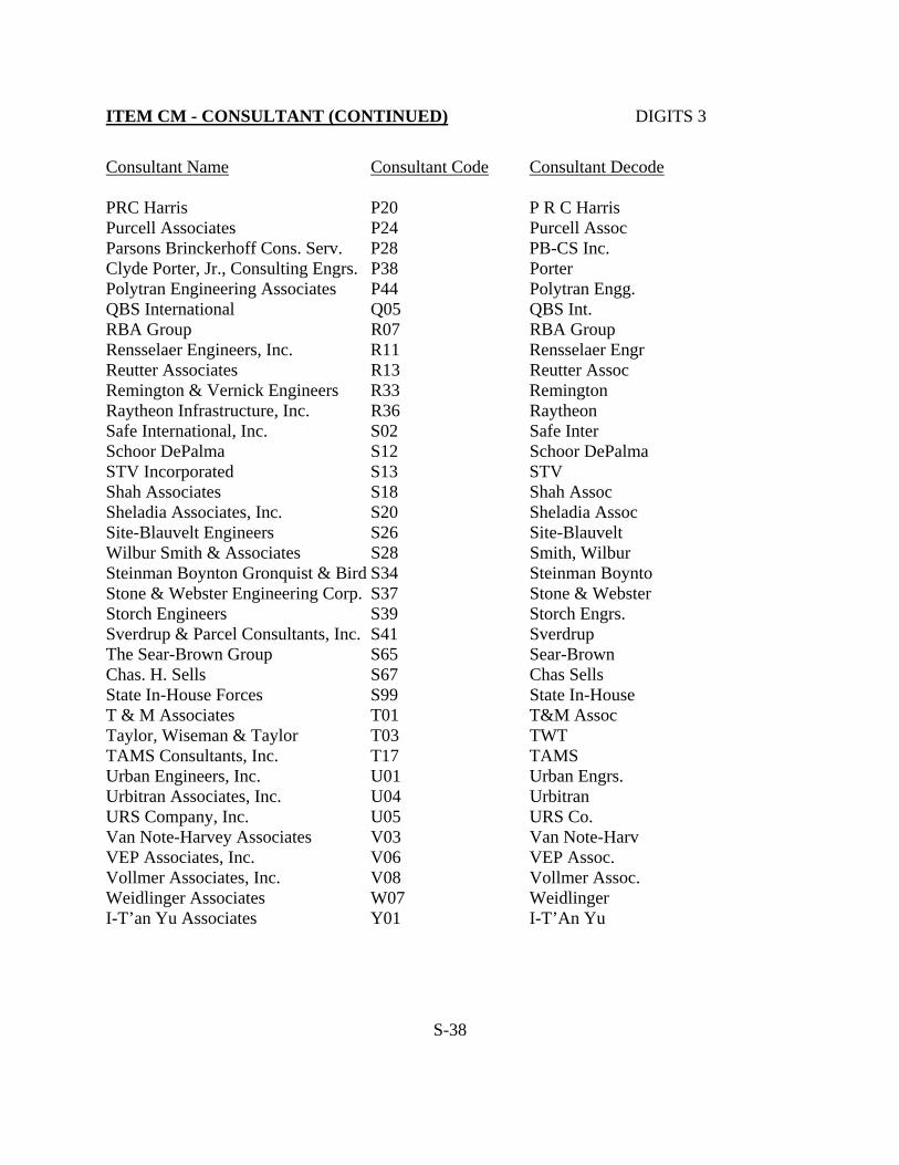
ITEM CM - CONSULTANT (CONTINUED) DIGITS 3
Consultant Name Consultant Code Consultant Decode PRC Harris P20 P R C Harris Purcell Associates P24 Purcell Assoc Parsons Brinckerhoff Cons. Serv. P28 PB-CS Inc. Clyde Porter, Jr., Consulting Engrs. P38 Porter Polytran Engineering Associates P44 Polytran Engg. QBS International Q05 QBS Int. RBA Group R07 RBA Group Rensselaer Engineers, Inc. R11 Rensselaer Engr Reutter Associates R13 Reutter Assoc Remington & Vernick Engineers R33 Remington Raytheon Infrastructure, Inc. R36 Raytheon Safe International, Inc. S02 Safe Inter Schoor DePalma S12 Schoor DePalma STV Incorporated S13 STV Shah Associates S18 Shah Assoc Sheladia Associates, Inc. S20 Sheladia Assoc Site-Blauvelt Engineers S26 Site-Blauvelt Wilbur Smith & Associates S28 Smith, Wilbur Steinman Boynton Gronquist & Bird S34 Steinman Boynto Stone & Webster Engineering Corp. S37 Stone & Webster Storch Engineers S39 Storch Engrs. Sverdrup & Parcel Consultants, Inc. S41 Sverdrup The Sear-Brown Group S65 Sear-Brown Chas. H. Sells S67 Chas Sells State In-House Forces S99 State In-House T & M Associates T01 T&M Assoc Taylor, Wiseman & Taylor T03 TWT TAMS Consultants, Inc. T17 TAMS Urban Engineers, Inc. U01 Urban Engrs. Urbitran Associates, Inc. U04 Urbitran URS Company, Inc. U05 URS Co. Van Note-Harvey Associates V03 Van Note-Harv VEP Associates, Inc. V06 VEP Assoc. Vollmer Associates, Inc. V08 Vollmer Assoc. Weidlinger Associates W07 Weidlinger I-T’an Yu Associates Y01 I-T’An Yu
S-38

ITEM CN - TYPE AND DATE OF PREVIOUS INSPECTION DIGITS 5 1. First Digit - Code "I" if the inspection is an interim (less than the regularly scheduled
interval) or code "S" if the inspection is in-depth at regularly scheduled interval (normal two year cycle). Code "E" for emergency inspection such as collision damage or flooding.
2. Remaining four digits (2 thru 5), should be coded for the month and year. Coding of his
item is independent of Item 90. When not applicable (e.g.-first cycle), leave all digits blank. Example: Interim inspection July, 1989 Code I0789 In-depth inspection July, 1989 Code S0789 ITEM CO - PREVIOUS CONSULTANT DIGITS 3 Use the three digit code, representing the consultant, involved in the previous inspection of the structure. The codes are the same as those used for Item CM. For consultant codes not listed, contact your project manager. ITEM CP - FEDERAL REPORT DIGIT 1 Leave blank if record is to included in reports to FHWA. The following codes should only be used if the record is to be excluded from FHWA reports. X - For railroad carrying bridges, tunnels and other related railroad structures. F - For all Federally owned bridges. P - For all privately owned bridges. R - All other bridges in various categories not otherwise listed here. D - Duplicate records.
L - Highway carrying bridges less than 20’ in length but at least 5’. Also, code Federal Item 112 “NBIS Bridge Length” as “N” and State Item CK must also be numeric.
If Item CP is coded incorrectly, code “B” to blank out code on the specific record.
S-39

ITEM CQ - BRIDGE LIST DIGIT 1 This item describes the list of bridges under which the structure is inspected. This item is for State in-house use and should be coded for state owned bridges only. Code "Y" to indicate bridges which have been included in proposed consultant bridge inspection lists, but which have not yet been inspected. This item should not be coded until the list of bridges is finalized. Once the inspection has been completed, this item should be coded "X" for consultant bridges when the SI&A sheet is updated. Code "Z" to indicate bridges for which a bridge replacement, rehabilitation or demolition project is in progress. ITEM CR - OFF-THE -ROUTE BRIDGE DIGIT 1 This item is coded to indicate bridges that are owned by the State but do not carry or intersect an Interstate, U.S. or State Highway. Bridges that meet the above criteria will have this Item coded with "A". This item is for State in-house use and should be coded for State owned bridges only. Leave blank if not applicable. Examples: A. The County Route 547 S.B. bridge over Manasquan River
(Structure No. 1333-175) would have this Item coded "A" since it does not carry or intersect a State Highway and is listed under Route 195.
B. The North Broad Street bridge over the Delaware Raritan Feeder Canal (Structure No. 3001-151) would have this Item left blank because North Broad Street is also Route U.S. 206 N.B. at the structure site. ITEM DA - DESCRIPTION OF PROPOSED IMPROVEMENTS DIGITS 215 Describe the proposed improvements to the subject structure. Abbreviations can be used; however, use common abbreviations and explain all points to avoid confusion. Code "X" in the first column (left justified) to blank out Item DA.
S-40

ITEM DJ - MINIMUM VERTICAL UNDERCLEARANCE DIGITS 4
INCLUDING SHOULDERS (XX.XX feet)
Record and code a four-digit number to represent in feet, minimum vertical clearance from the
roadway (including shoulders) beneath the structure to the underside of the superstructure. Code
zeros for structures over any other feature.
In addition to coding this Item on sheet 1, it should also be coded on sheets 2 and A thru Z.
Sheet 2 would be coded the same as sheet 1, but sheets A thru Z would be coded for the
individual features intersected.
When sheets A thru Z are coded, sheet 1 should always be coded for the absolute minimum of all
features beneath the structure.
ITEM FA - FHWA SCOUR REPORTING CATEGORIES DIGITS 2
Code the current FHWA Reporting Category for the bridge based upon the information and
results obtained during the Bridge Scour Evaluation program:
LOW RISK BRIDGE - STAGE 2 NOT REQUIRED and STAGE 2 DONE
Code Reporting Category Comments
01 Assessed (old bridge) Pre HEC-18 Design - Stage 1 not performed
11 Assessed (new/old
bridge with Scour
Countermeasures )
Foundations designed in accordance with HEC-18
or Scour Countermeasures designed in accordance
with HEC-23
02 Screened Stage 1 performed
03 Culvert
SCOUR SUSCEPTIBLE BRIDGE - STAGE 2 REQUIRED
Code Reporting Category Comments
04 Screened Known foundation details and non-tidal waterway
05 Unknown Foundations
06 Tidal Waterway Foundation details known
OTHER CATEGORIES
Code Reporting Category Comments
07 Scour Critical As determined by Stage 2 analysis
08 Analyzed for Scour Stage 2 Complete
Leave blank if not applicable
S-41

ITEM FB - DATE OF STAGE I SCOUR EVALUATION DIGITS 4 Code the month and year of the Stage I Screening and Prioritization field survey as follows:
Field Inspection Date MMYY Leave blank if not applicable
ITEM FC - STAGE I SCOUR EVALUATION CONSULTANT DIGITS 3 Use the three digit code, representing the consultant, who made the STAGE I Screening and Prioritization survey of the structure. The codes are the same as those used for Item CM. For consultant codes, contact your project manager.
Leave blank if not applicable.
ITEM FD - STAGE I SCOUR EVALUATION PRIORITIZATION DIGIT 1 CATEGORY
Code the Prioritization Category of the bridge as determined from the STAGE I Screening and Prioritization survey. The codes range from 1 (representing the highest potential for scour damage) to 4 (representing the lowest potential for scour damage).
Leave blank if not applicable.
ITEM FE - STAGE I SCOUR EVALUATION SUFFICIENCY DIGITS 3 RATING Code the Sufficiency Rating of the bridge as determined from the STAGE I Screening and Prioritization survey. The codes range from 0 (representing a fully deficient bridge) to 100 (representing a fully sufficient bridge).
Scour Sufficiency Rating is 50 - Code b50. Leave blank if not applicable.
ITEM FF - DATE OF STAGE II SCOUR EVALUATION DIGITS 4 Code the month and year of the STAGE II In-Depth Scour Evaluation field survey as follows:
Field Inspection Date MMYY Leave blank if not applicable
S-42

ITEM FG - STAGE II SCOUR EVALUATION CONSULTANT DIGITS 3 Use the three digit code, representing the consultant, who made the Stage II In-Depth Scour Evaluation survey of the structure. The codes are the same as those used for Item CM. For consultant codes, contact your project manager.
Leave blank if not applicable.
ITEM FH - SCOUR CRITICAL ELEMENTS DIGITS 114 List the substructure elements determined to be scour critical based on the Stage II In-Depth Scour Evaluation survey. Abbreviations can be used; however, use common abbreviations to avoid confusion. Code “X” in the first column (left justified to blank out Item FH.
Leave blank if not applicable.
ITEM FI - RECOMMENDED SCOUR COUNTERMEASURES DIGITS 104 List the scour countermeasures recommended based on the Stage II In-Depth Scour Evaluation survey. Abbreviations can be used; however, use common abbreviations can to avoid confusion. Code “X” in the first column (left justified) to blank out Item FI.
Leave blank if not applicable.
ITEM FJ - SCOUR COUNTERMEASURES COST DIGITS 5 Code the estimated cost of Recommended Scour Countermeasures indicated in Item FI in thousands of dollars. This Item should include all costs normally associated with the type of scour countermeasure recommended for the bridge.
Leave blank if not applicable.
ITEM FK - SCOUR COUNTERMEASURES INSTALLED/TYPE DIGITS 3 Using the following codes, indicate the type of scour countermeasures installed at the bridge. If more than three types of scour countermeasures are installed, code the three most prevalent. The left position should be coded first.
S-43
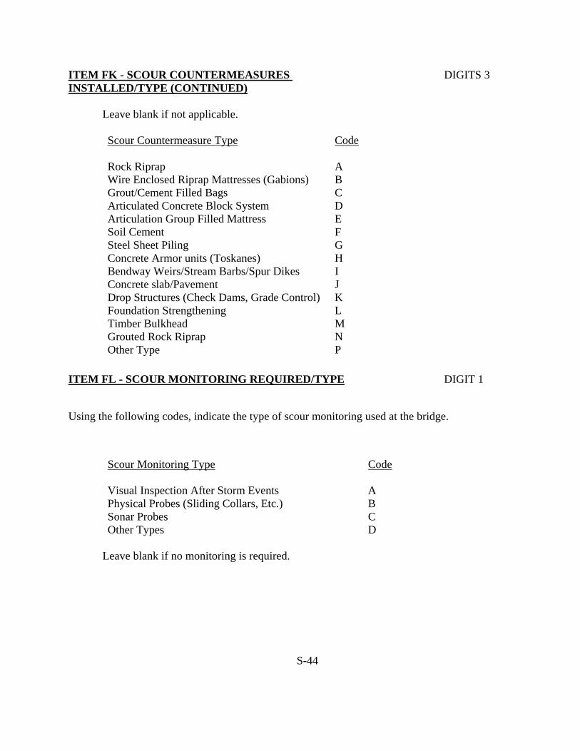
ITEM FK - SCOUR COUNTERMEASURES DIGITS 3 INSTALLED/TYPE (CONTINUED)
Leave blank if not applicable. Scour Countermeasure Type Code
Rock Riprap A Wire Enclosed Riprap Mattresses (Gabions) B Grout/Cement Filled Bags C Articulated Concrete Block System D Articulation Group Filled Mattress E Soil Cement F Steel Sheet Piling G Concrete Armor units (Toskanes) H Bendway Weirs/Stream Barbs/Spur Dikes I Concrete slab/Pavement J Drop Structures (Check Dams, Grade Control) K Foundation Strengthening L Timber Bulkhead M Grouted Rock Riprap N Other Type P
ITEM FL - SCOUR MONITORING REQUIRED/TYPE DIGIT 1 Using the following codes, indicate the type of scour monitoring used at the bridge.
Scour Monitoring Type
Code
Visual Inspection After Storm Events A Physical Probes (Sliding Collars, Etc.) B Sonar Probes C Other Types D
Leave blank if no monitoring is required.
S-44

ITEM FM - INCIDENTS REPORTED DIGIT 1 Using the following codes, indicate if there have been any reported incidents of objects being dropped from the highway carrying structure:
Code Description
Y There has been at least one (1) incident reported M There have been multiple incidents reported N There are no incidents reported
Note: The Bridge Management System maintains a list of reported incidents to date. ITEM FN - FENCING WARRANTED DIGIT 1 Using the following codes, indicate if fencing is warranted on the structure (per Design Manual Section 23):
Code Description
Y Conditions warrant chain link fencing on the structure N Conditions do not warrant chain link fencing on the structure
Note: This item should be consistent with Federal Item 42 (Type of Service). If Item 42 is
coded for pedestrian traffic, the correct code is “Y”. ITEM FO - PEDESTRIAN TRAFFIC FENCING STATUS DIGIT 1 Bridge Inspection shall include the recording of information on the CHAIN LINK FENCE field note form so that an evaluation of the current status of the fencing and its adequacy can be made.
The report of this information shall be as follows: Code Description
0 Inspected fencing does not meet currently acceptable standards or a
fence is warranted and none is provided 1 Inspected fencing meets currently acceptable standards N Not applicable or fencing is not warranted
S-45

ITEM FP - FENCING IMPROVEMENT COST DIGITS 4 Code a 4-digit number to represent the cost of the proposed structure fencing improvements in thousands of dollars.
Example: Fencing Improvement Cost $63,750. Code: 0064 Leave blank is there is no fencing improvement cost.
ITEM FQ - LATEST IN-DEPTH FRACTURE CRITICAL/ DIGITS 4 PIN-HANGER INSPECTION DATE Code the month, date and year of the most recent in-depth fracture critical or pin-hanger inspection as follows:
Latest Inspection Date MM, DD,YYYY Leave blank if not applicable
ITEM FR - IN-DEPTH FRACTURE CRITICAL/ DIGITS 3 PIN-HANGER CONSULTANT Use the three digit code, representing the consultant, who made the latest in-depth fracture critical or pin-hanger inspection of the structure. The codes are the same as those used for Item CM. For consultant codes, contact your project manager.
Leave blank if not applicable.
ITEM FS - IN-DEPTH FRACTURE CRITICAL MEMBERS DIGITS 120 INSPECTED List the structural members which require an in-depth fracture critical inspection. This list should include all FCM’s, not just those that require special in-depth inspections under In-Depth FCM Contracts. Abbreviations can be used; however, use common abbreviations to avoid confusion. Code “X” in first column (left justified) to blank out Item FS.
Leave blank if not applicable.
ITEM FT - COMBINATION IN-DEPTH FRACTURE CRITICAL DIGIT 1 MEMBER/PIN-HANGER INSPECTION Indicate by a code of “1” for “Yes” when the date coded for Item FQ (Last In-depth Fracture Critical/Pin Hanger Inspection Date) represents an inspection of both Fracture Critical Members and Pin-Hanger Assemblies.
Leave blank if not applicable.
S-46

ITEM FV - ASSIGNED ROUTE MILEPOINT DIGITS 6 Based on the Route identified in Item AA, code a six digit number representing the milepoint of the structure to thousandths of a mile (xxx.xxx miles). Code all zeros if a milepoint location cannot be determined or is not appropriate.
Note: This Item is only coded for NJDOT owned bridges.
ITEM FW - ESTIMATED AVERAGE DAILY TRAFFIC DIGIT 1 If the average daily traffic coded for Item 29 on sheet 1 is estimated or has been projected from actual data over four years old, code “Y” (YES) for this item.
If the average daily traffic coded for Item 29 on sheet 1 is based on a measured ADT or has been projected from actual data less than four years old, leave this item blank. ITEM FX - FEDERAL ERROR CANNOT BE CORRECTED DIGIT 1 When an unusual situation causes a Federal Edit error to be indicated on the SI&A which cannot be corrected without coding fields incorrectly, code this Item “Y” (Yes).
NOTE: This Item should not be coded “Y” without first explaining the reason for the uncorrected error to your project manager and obtaining his concurrence.
Leave blank if not applicable.
ITEM GA - IS PAINTING REQUIRED DIGIT 1
Using the following codes, indicate if any portion of the structure requires painting:
Code Description Y Parts of the structure require painting N No parts of the structure require painting
NOTE: If portions of encased steel members are exposed due to deterioration, the correct code is “Y”.
If the code for this Item is “N”, leave Items GB through GR blank. NOTE: The coding for Items GB through GR should be collected in the field using the
current form titled “PAINT INSPECTION” and then transferred to the appropriate database fields.
S-47

ITEM GB - ENVIRONMENT DIGITS 2 Using the following codes, indicate the type of environment that the bridge is located in:
Code Description
01 Rural or Industrial, Mild Exposure 02 Industrial, Severe Exposure 3A Marine, Mild Exposure 3B Marine, Severe Exposure
ITEM GC- DATE OF PAINT INSPECTION DIGITS 6 Code the date of the latest paint inspection using six digits representing the year, month and day (MM,DD,YYYY).
Example: The latest paint inspection was conducted on July 8, 1994. Therefore, the
correct code would be “07081994". ITEMS GD THRU GO - PAINT CONDITION RATINGS EACH DIGITS 2 Code the paint condition ratings for the Items listed below using the “PAINT INSPECTION” field note form:
Item Description
GD Fascia Beam GE Fascia Bottom Flange GF Interior Beam GH Interior Bottom Flange GI Beam Ends GJ Connections GK Bracings GL Bearings GM Substructure GN Above Deck Superstructure GO Railings/Fence
S-48

ITEMS GD THRU GO - PAINT CONDITION RATINGS EACH DIGITS 2 (CONTINUED) Using the codes listed below, code the paint condition ratings for the above items (Code the average for the Item, not the worst area):
Code Description
00 100% Rust 01 50-100% Rust 02 33-50% Rust 03 16-33% Rust 04 10-16% Rust 05 3-10% Rust 06 1-3% Rust 07 0.3-1% Rust 08 0.1-0.3% Rust 09 .03-0.1% Rust 10 0-.03% Rust
If a specific Item does not require painting (except weathering steel), leave the code blank. For weathering steel, see Appendix G for coding instructions.
ITEMS GP AND GQ -PAINT REMARKS 1 & 2 EACH DIGITS 89 In the space provided, indicate any remarks noted on the “PAINT INSPECTION” field note form. Abbreviations can be used; however, use common abbreviations to avoid confusion. Code “X” in first column (left justified) to blank out Items GP and GQ.
Leave blank if not applicable. ITEM GR - DATE OF LAST PAINTING DIGITS 4 Code the dates of the latest bridge painting using four digits representing the year and month (YY,MM). This date is usually stenciled on the bridge fascia girder. If the bridge was spot painted only, do not revise the previously coded date of painting. Also, if the date of painting is unknown, leave this Item blank.
Example: The date of latest painting is 07/94 (stenciled on the fascia girder). Therefore, the correct code would be “9407”.
S-49
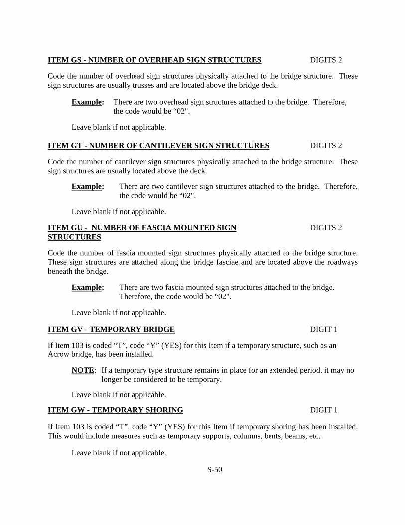
ITEM GS - NUMBER OF OVERHEAD SIGN STRUCTURES DIGITS 2 Code the number of overhead sign structures physically attached to the bridge structure. These sign structures are usually trusses and are located above the bridge deck.
Example: There are two overhead sign structures attached to the bridge. Therefore, the code would be “02".
Leave blank if not applicable.
ITEM GT - NUMBER OF CANTILEVER SIGN STRUCTURES DIGITS 2 Code the number of cantilever sign structures physically attached to the bridge structure. These sign structures are usually located above the deck.
Example: There are two cantilever sign structures attached to the bridge. Therefore, the code would be “02".
Leave blank if not applicable.
ITEM GU - NUMBER OF FASCIA MOUNTED SIGN DIGITS 2 STRUCTURES Code the number of fascia mounted sign structures physically attached to the bridge structure. These sign structures are attached along the bridge fasciae and are located above the roadways beneath the bridge.
Example: There are two fascia mounted sign structures attached to the bridge. Therefore, the code would be “02".
Leave blank if not applicable.
ITEM GV - TEMPORARY BRIDGE DIGIT 1 If Item 103 is coded “T”, code “Y” (YES) for this Item if a temporary structure, such as an Acrow bridge, has been installed.
NOTE: If a temporary type structure remains in place for an extended period, it may no longer be considered to be temporary.
Leave blank if not applicable.
ITEM GW - TEMPORARY SHORING DIGIT 1 If Item 103 is coded “T”, code “Y” (YES) for this Item if temporary shoring has been installed. This would include measures such as temporary supports, columns, bents, beams, etc.
Leave blank if not applicable.
S-50

ITEM GX - TEMPORARY REPAIRS DIGIT 1 If Item 103 is coded “T”, code “Y” (YES) for this Item if temporary repairs have been made. Temporary repairs are defined as repairs designed as a short term solution and would include, as an example, the placement of steel plates over holes in the deck.
Leave blank if not applicable. ITEM GY - TEMPORARY MEASURES DIGIT 1 If Item 103 is coded “T”, code “Y” (YES) for this item if temporary measures have been taken at the bridge. Temporary measures would include barricaded lanes to keep a bridge open to traffic or any similar situations.
Leave blank if not applicable.
ITEM GZ - TEMPORARY CONDITION DESCRIPTION DIGITS 30 In the space provided, describe the temporary condition which exists at the bridge if Items GW to GY are coded “Y”. If Item GV (Temporary Bridge) is coded “Y”, leave this Item blank. Abbreviations can be used; however, use common abbreviations to avoid confusion. Code “X” in first column (left justified) to blank out Item GZ.
Leave blank if not applicable.
ITEM HA - BRIDGE NOISE BARRIER DIGITS 10 Using one of the codes listed below, code in the first position the letter representing the type material used for the first type of bridge mounted noise barrier:
Code Description
T Timber C Concrete P Prestressed Concrete A Aluminum S Steel O Other
S-51

ITEM HA - BRIDGE NOISE BARRIER (CONTINUED) DIGITS 10 In the next four positions, code a four digit number representing the height of the noise barrier in feet and hundredths of a foot (Do not include the height of any barrier curb or parapet).
If there are two types of bridge mounted noise barriers, repeat the above coding sequence for the second type of noise barrier.
Example: A five foot six inch (5'-6") high timber noise barrier would be coded
“T0550" Leave blank if not applicable
ITEM HB - PROJECT PROGRAMMING, BRIDGE LIST ID DIGITS 5
For bridge inspection projects code the ID of the bridge list that is to be inspected by a consultant in a bridge inspection contract or by in-house personnel for an in-house bridge inspection project. The item would be coded left justified.
Example: XYZ Consultants was selected to inspect 35 State owned bridges. The bridge list ID for this project is C94. The item should be coded C94bb
Example: XYZ Consultants was selected to inspect 22 Morris County bridges. The
bridge list ID for this project is C95. This item should be coded 14C95
Notice that for County projects the first 2 digits will be the 3rd & 4 digits of the County’s route number. The route number for Morris County is 9014b.
Example: A new in-house bridge list has been assigned to in-house personnel. The
bridge list ID for this project is J. This item should be coded Jbbbb
ITEM HC - PROJECT PROGRAMMING, SELECTED DIGITS 3 CONSULTANT
Use the three digit code, representing the consultant, who was selected by the consultant selection committee to inspect the bridges in Item HB above. The codes are the same as those used for Item CM. For consultant codes see your project engineer.
Example: XYZ Consultants was selected to inspect 35 State Owned bridges. Their consultant code is X01. The item should be coded X01
Do not code this item for in-house bridge inspection projects.
S-52

ITEM HD - PROJECT PROGRAMMING, TWO CYCLE DIGIT 1 INSPECTION CONTRACT Code whether the consultant bridge inspection contract is a one or two cycle inspection contract.
Format: Y = Yes N = No
Code Y for a 2 cycle consultant bridge inspection contract Code N for a 1 cycle consultant bridge inspection contract.
Do not code this item for in-house bridge inspection projects.
ITEM HE - PROJECT PROGRAMMING, NOTICE TO DIGITS 16 PROCEED DATES (DATE) Code the date that the consultant received notice to proceed on the bridge inspection contract.
Example: The consultant received NTP on 6/1/94 for the 1st inspection in a two cycle bridge inspection contract. The item should be coded 060194bbbbbb
Example: The same consultant in the above example received NTP on 8/16/96 for
the 2nd inspection in the two cycle bridge inspection contract. The item should be coded 060194081696
Do not code this item for in-house bridge inspection projects.
ITEM HF - PROJECT PROGRAMMING, STATE PROJECT DIGITS 3 MANAGER
Code the initials of the NJDOT project manager who has been assigned the consultant bridge inspection contract or who has been assigned the bridge in an in-house bridge inspection project.
Example: XYZ Consultants was selected to inspect 35 State owned bridges. The
NJDOT project manager assigned to this project is Joseph T. Bridge.
The item should be coded JTB
S-53
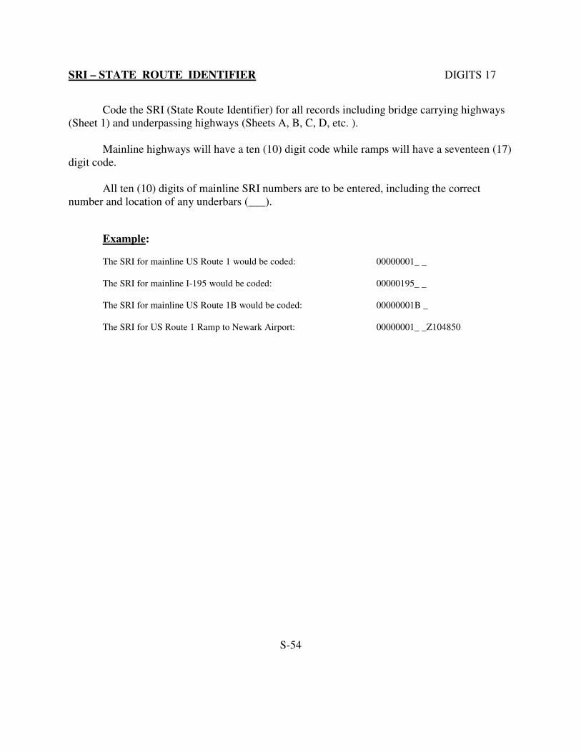
SRI – STATE ROUTE IDENTIFIER DIGITS 17
Code the SRI (State Route Identifier) for all records including bridge carrying highways
(Sheet 1) and underpassing highways (Sheets A, B, C, D, etc. ).
Mainline highways will have a ten (10) digit code while ramps will have a seventeen (17)
digit code.
All ten (10) digits of mainline SRI numbers are to be entered, including the correct
number and location of any underbars (___).
Example:
The SRI for mainline US Route 1 would be coded: 00000001_ _
The SRI for mainline I-195 would be coded: 00000195_ _
The SRI for mainline US Route 1B would be coded: 00000001B _
The SRI for US Route 1 Ramp to Newark Airport: 00000001_ _Z104850
S-54

APPENDIX A
ADDITIONAL CODING INSTRUCTIONS FOR SELECTED FEDERAL ITEMS

ITEM 2 - HIGHWAY DISTRICT DIGITS 2 The highway district in which the bridge is located shall be represented by a two-digit code. Existing numbers shall be used where districts are identified by number. where districts are identified by name, a code number shall be assigned based on an alphabetical listing of the districts. DISTRICT 01 Bergen, Essex, Hudson, Morris, Passaic, Sussex, Union, Warren (NORTH) (north of US 22) DISTRICT 02 Hunterdon, Mercer, Middlesex, Monmouth, Ocean, Somerset, (CENTRAL) Warren (south of US 22) DISTRICT 03 Atlantic, Burlington, Camden, Cape May, Cumberland, (SOUTH) Gloucester, Salem
Example - The highway district for a bridge in Hunterdon County is coded as 02. ITEM 3 - COUNTY (PARISH) CODE DIGITS 3 Counties shall be identified with the code scheme specified below. New Jersey Counties shall be coded as a three digit number. Given below are their respective numbers.
Atlantic 001 Middlesex 023 Bergen 003 Monmouth 025 Burlington 005 Morris 027 Camden 007 Ocean 029 Cape May 009 Passaic 031 Cumberland 011 Salem 033 Essex 013 Somerset 035 Gloucester 015 Sussex 037 Hudson 017 Union 039 Hunterdon 019 Warren 041 Mercer 021
NOTE: These county codes are also shown in the Geographic Identification Code
Scheme included in Appendix E. ITEM 4 - PLACE CODE Cities, towns, townships, villages and other census-designated places shall be identified using the Federal Information Processing Standards (FIPS) codes given in the current version of the Census of Population and Housing - Geographic Identification Code Scheme. If there is no FIPS place code, then code all zeros. NOTE: The FIPS place codes referred to can be obtained from the Geographic
Identification Code Scheme which is included as Appendix E.
SA-1
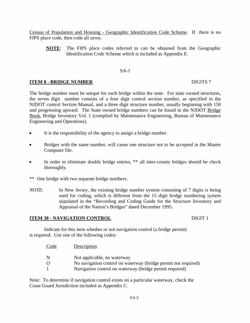
Census of Population and Housing - Geographic Identification Code Scheme. If there is no FIPS place code, then code all zeros. NOTE: The FIPS place codes referred to can be obtained from the Geographic
Identification Code Scheme which is included as Appendix E.
SA-1
ITEM 8 - BRIDGE NUMBER DIGITS 7 The bridge number must be unique for each bridge within the state. For state owned structures, the seven digit number consists of a four digit control section number, as specified in the NJDOT control Section Manual, and a three digit structure number, usually beginning with 150 and progressing upward. The State owned bridge numbers can be found in the NJDOT Bridge Book, Bridge Inventory Vol. 1 (complied by Maintenance Engineering, Bureau of Maintenance Engineering and Operations). • It is the responsibility of the agency to assign a bridge number. • Bridges with the same number, will cause one structure not to be accepted in the Master
Computer file. • In order to eliminate double bridge entries, ** all inter-county bridges should be check
thoroughly. ** One bridge with two separate bridge numbers. NOTE: In New Jersey, the existing bridge number system consisting of 7 digits is being
used for coding, which is different from the 15 digit bridge numbering system stipulated in the “Recording and Coding Guide for the Structure Inventory and Appraisal of the Nation’s Bridges” dated December 1995.
ITEM 38 - NAVIGATION CONTROL DIGIT 1 Indicate for this item whether or not navigation control (a bridge permit) is required. Use one of the following codes:
Code Description
N Not applicable, no waterway O No navigation control on waterway (bridge permit not required) 1 Navigation control on waterway (bridge permit required)
Note: To determine if navigation control exists on a particular waterway, check the Coast Guard Jurisdiction included as Appendix C.
SA-2
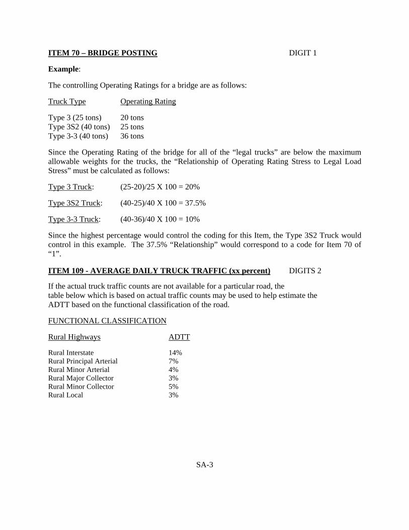
ITEM 70 – BRIDGE POSTING DIGIT 1 Example: The controlling Operating Ratings for a bridge are as follows: Truck Type Operating Rating Type 3 (25 tons) 20 tons Type 3S2 (40 tons) 25 tons Type 3-3 (40 tons) 36 tons Since the Operating Rating of the bridge for all of the “legal trucks” are below the maximum allowable weights for the trucks, the “Relationship of Operating Rating Stress to Legal Load Stress” must be calculated as follows: Type 3 Truck: (25-20)/25 X 100 = 20% Type 3S2 Truck: (40-25)/40 X 100 = 37.5% Type 3-3 Truck: (40-36)/40 X 100 = 10% Since the highest percentage would control the coding for this Item, the Type 3S2 Truck would control in this example. The 37.5% “Relationship” would correspond to a code for Item 70 of “1”. ITEM 109 - AVERAGE DAILY TRUCK TRAFFIC (xx percent) DIGITS 2 If the actual truck traffic counts are not available for a particular road, the table below which is based on actual traffic counts may be used to help estimate the ADTT based on the functional classification of the road. FUNCTIONAL CLASSIFICATION Rural Highways ADTT Rural Interstate 14% Rural Principal Arterial 7% Rural Minor Arterial 4% Rural Major Collector 3% Rural Minor Collector 5% Rural Local 3%
SA-3

ITEM 109 - AVERAGE DAILY TRUCK TRAFFIC (CONTINUED) FUNCTIONAL CLASSIFICATION Urban Highways ADTT Urban Interstate 9% Urban Freeways or Expressways 5% Urban Principal Arterial 4% Urban Minor Arterial 4% Urban Collector 3% Urban Local 1% Note: Leave blank if Item 29 - Average Daily Traffic is not greater than 100.
SA-4

ITEM 110 - DESIGNATED NATIONAL NETWORK DIGIT 1 In New Jersey, the following highways are included in the Designated System for Double Bottom Trucks as identified in the Code of Federal Regulations (23 CFR 658).: Mainline Roads
Federal Highway Administration, DOT Part 658, App. A
Appendix A - The National Network
Posted Route No.
From To
NJ 42………………… US 322………………. US130………………..
Atlantic City Expressway at NJ 168 Washington Pennsylvania St. Line US 322 Bridgeport
I-295 Bellmawr US 130 Bridgeport I-295 Logan Township
US 130………………. NJ440………………..
NJ 44 West Deptford I-95 Edison
I-295 West Deptford New York St. Line at Outerbridge Crossing
NJ 81……………….. I-95 Elizabeth US 1 Elizabeth
The following two sections of the New Jersey Turnpike were added to the Interstate System on March 3, 1983, and are not signed as Interstate. The route segments are listed since the public may be unaware of this designation.
Pennsylvania Pennsylvania St. Line Exit 6 Mansfield Turnpike Connector New Jersey Exit 6 Mansfield Exit 10 Edison Ramps
Any ramps which connect any of the above routes to each other is also part of the Designated National Network.
SA-5

APPENDIX B
STRAHNET HIGHWAY DESIGNATION

Item 100 - STRAHNET Highway Designation STRAHNET Highways in New Jersey
Interstate STRAHNET - Item 100 = 1
1. Includes all mainline Interstate Highways 2. Includes all Interstate Highway ramps that connect the other STRAHNET Highways.
Non-Interstate STRAHNET - Item 100 = 2
FROM MILEPOST TO MILEPOST FACILITY
N.J. Rt. 31 (Mercer & Hunterdon Co.)
4.84 (I-95)
16.36 (U.S. Rt. 202)
N/A
U.S. Rt. 202 (Hunterdon & Somerset Co.)
5.70 (N.J. Rt. 31)
25.88 (I-287)
N/A
STRAHNET Connector Routes - Item 100 = 3
ROAD FROM MILEPOST TO MILEPOST FACILITY
U.S. Rt. 9 (Middlesex Co.)
129.71 (N.J. Rt. 35)
132.85 (N.J. Route 440)
Fort Monmouth
U.S. Rt. 9 (Monmouth & Ocean Co.)
98.65 (N.J. Rt. 70)
106.96 (I-195)
Naval Air Engineering Center Lakehurst
N.J. Rt. 18 (Monmouth & Middlesex Co.)
19.02 (N.J. Rt. 34)
39.58 (New Jersey Turnpike, I-95)
Naval Weapons Station Earle
N.J. Rt. 34 (Monmouth Co.)
10.28 (Naval Weapons Station Earle)
12.27 (N.J. Rt. 18)
Naval Weapons Station Earle
N.J. Rt. 35 (Monmouth & Middlesex Co.)
29.65 (Wycoff Road)
49.38 (U.S. Rt. 9)
Fort Monmouth
N.J. Rt. 36 (Monmouth Co.)
0.00 (Garden State Parkway)
1.27 Co. Rt. 547 Wycoff Road
Fort Monmouth
N.J. Rt. 68 (Burlington Co.)
1.05 (Fort Dix)
7.97 (U.S. Rt. 206)
Fort Dix
N.J. Rt. 70 (Ocean Co.)
38.43 (Co. Rt. 539)
49.90 (U.S. Rt. 9)
Naval Air Engineering Center Lakehurst
U.S. Rt. 130 (Burlington Co.)
54.90 (I-295)
55.46 (Co. Rt. 545)
McGuire Air Force Base
SB-1

STRAHNET Connector Routes - Item 100 = 3
ROAD FROM MILEPOST TO MILEPOST FACILITY
U.S. Rt. 206 (Burlington & Mercer Co.)
33.64 (N.J. Rt. 68)
39.63 (I-295)
Fort Dix
N.J. Route 440 (Middlesex Co.)
0.00 (New Jersey Turnpike, I-95)
2.06 (U.S. Route 9)
Fort Monmouth
Garden State Parkway (Monmouth & Middlesex Co.)
106.39 (N.J. Rt. 36)
129.72 (New Jersey Turnpike, I-95)
Fort Monmouth
Co. Rt. 537 (Burlington Co.)
27.40 (Rt. 68)
28.38 (Co. Rt. 545)
McGuire Air Force Base
Co. Rt. 539 (Ocean Co.)
25.36 (N.J. Rt. 70)
29.99 (Naval Air Engineering Center Lakehurst)
Naval Air Engineering Center Lakehurst
Co. Rt. 545 (Burlington Co.)
4.50 (McGuire Air Force Base)
6.94 (Co. Rt. 537)
McGuire Air Force Base
Co. Rt. 545 (Burlington Co.)
13.78 (U.S. Rt. 206)
14.05 (U.S. Route 130)
McGuire Air Force Base
Co. Rt. 547 (Wycoff Road) (Monmouth Co.)
27.08 (N.J. Rt. 36)
27.36 (N.J. Rt. 35) and
Fort Monmouth
Co. Rt. 547 (Ocean Co.)
0.00 (N.J. Rt. 70)
0.81 (Naval Air Engineering Center Lakehurst)
Naval Air Engineering Center Lakehurst
Co. Rt. 680 (Burlington Co.)
0.00 (McGuire Air Force Base)
2.48 (Co. Rt. 545)
McGuire Air Force Base
Corbin Street (Union Co.)
0.00 (Lyle King Blvd.)
0.32 (North Fleet Avenue)
Port of New York & New Jersey
Lyle King Blvd. (Union Co.)
0.00 (Corbin Street)
0.50 (McLester Street)
Port of New York & New Jersey
McLester Street (Union Co.)
0.00 (North Avenue East)
1.00 (Lyle King Blvd.)
Port of New York & New Jersey
North Avenue East (Union Co.)
1.45 (New Jersey Turnpike Exit 13A)
2.46 (McLester Street)
Port of New York & New Jersey
SB-2
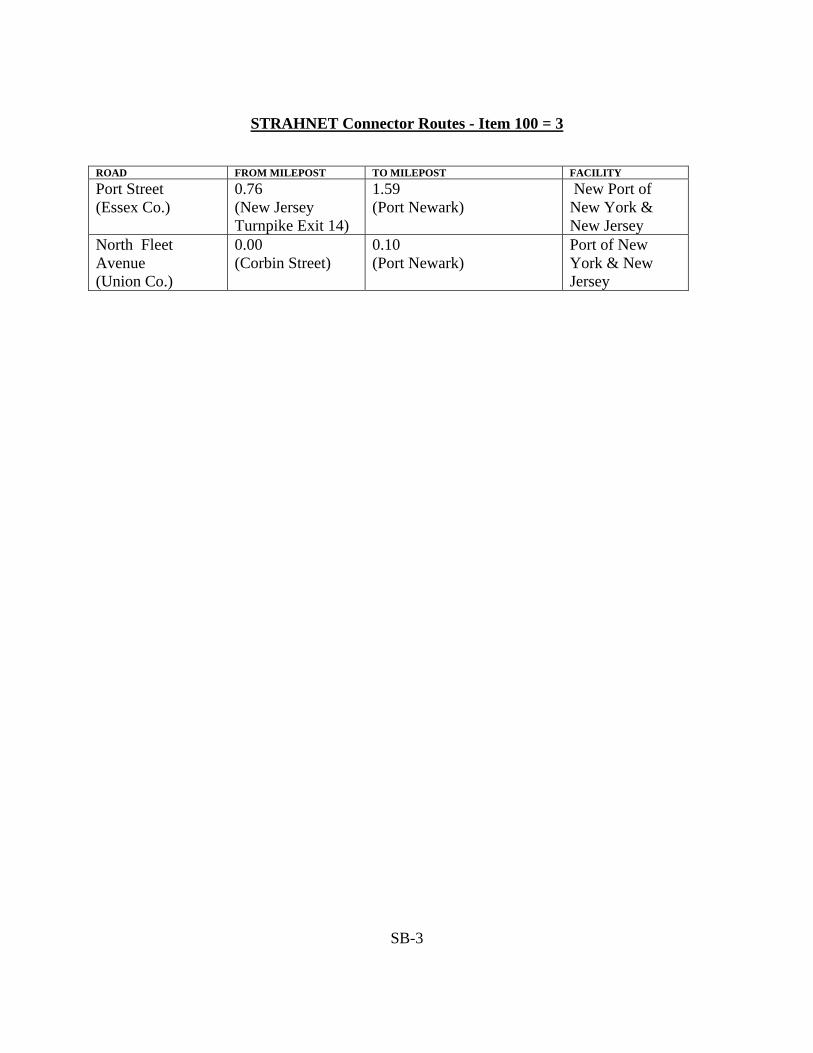
STRAHNET Connector Routes - Item 100 = 3
ROAD FROM MILEPOST TO MILEPOST FACILITY
Port Street (Essex Co.)
0.76 (New Jersey Turnpike Exit 14)
1.59 (Port Newark)
New Port of New York & New Jersey
North Fleet Avenue (Union Co.)
0.00 (Corbin Street)
0.10 (Port Newark)
Port of New York & New Jersey
SB-3

SB-4

SB-5

SB-6

SB-7

SB-8
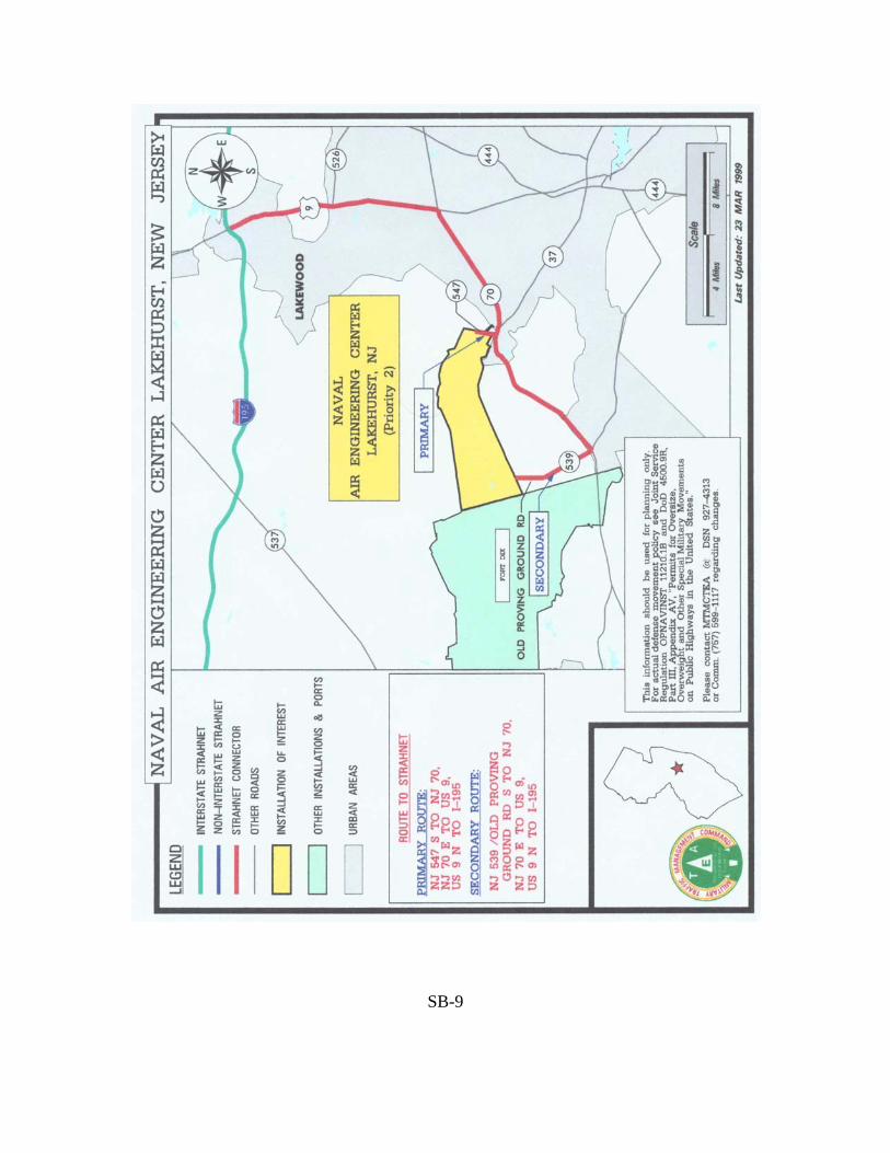
SB-9

SB-10

APPENDIX C
COAST GUARD JURISDICTION

Coast Guard Jurisdiction First and Fifth Coast Guard Districts
New Jersey
The First and Fifth Coast Guard Districts include all of the State of New Jersey. The First Coast Guard District includes that portion of New Jersey north of 30° 57’ north latitude, east of 74° 27’ west longitude, and northeast of a line from 39° 57’ north, 74° 27’ west northwest to the New York, New Jersey and Pennsylvania boundaries at Tristate; thence, southwesterly along a long line bearing 219 T to the point of intersection 36° 43’ north latitude, 67° 30’ west longitude with a line bearing 122 T from the New Jersey shoreline at 39° 57’ north latitude (in the vicinity of Tom’s River, New Jersey); thence, northwesterly along this line to the coast. The Fifth Coast Guard District includes the rest of New Jersey south of the above noted limits. The following list makes no attempt to delimit the jurisdiction of the Coast Guard under the Federal Water Pollution Control Act. “Navigable Waters of the United States” and “navigable waters,” as used in sections 311 and 312 of the Federal Water Pollution Control Act, as amended, 33 U.S.C. 1321 and 1322, mean: (1) Navigable waters of the United States as defined in the following paragraph and all
waters within the United States tributary thereto; and (2) Other waters over which the Federal Government may exercise Constitutional
authority. Unless noted otherwise, each entry in the following list represents solely the opinion of the Coast Guard as to the extent of its own jurisdiction and no entry represents in any way an opinion as to the extent of the jurisdiction of the United States or any of its other agencies. The extent of the jurisdiction of the United States can be conclusively determined only by judicial or legislative processes. Unless there is a judicial or legislative decision to the contrary for a specific body of water, the Coast Guard considers the following waters subject to general Coast Guard jurisdiction whether or not they are named in the following list:
SC-1

(1) Navigable waters of the United States. The following waters are included unless
Congress has specifically designated an area or body of water not to be navigable water of the United States:
(a) Territorial seas of the United States. The territorial sea consists of a belt, three
nautical miles wide, that is adjacent to the coast and seaward of the territorial sea baseline.
(b) Internal waters of the United States that are subject to tidal influence. The shoreward limit is the line of the shore reached by the plane of mean high water. If the limit of jurisdiction in a bay or estuary is determined by the limit of tidal influence, general jurisdiction extends only so far as the area is subject to inundation by mean high waters. (General jurisdiction may extend beyond and the limit of tidal influence on the basis of one or more of the following tests).
(c) Internal waters of the United States not subject to tidal influence that: (i) Are or have been used, or are or have been susceptible for use, by themselves
or in connection with other waters, as highways for substantial interstate or foreign commerce, not withstanding natural or man-made obstructions that require portage, or
(ii) A governmental or non-governmental body, having expertise in waterway improvement, determines to be capable of improvement at a reasonable cost (a favorable balance between cost and need) to provide, by themselves or in connection with other waters, highways for substantial interstate or foreign commerce.
(2) Other waters that are located on lands, owned by the United States, with respect to which jurisdiction has been accepted in accordance with 33 U.S.C. 733 by the authorized federal officer having custody, control, or other authority over them.
(3) Other waters that are located on lands, owned by the United States, with respect to which the United States retains concurrent or exclusive jurisdiction from the date that the State in which the lands are located entered the Union.
General jurisdiction over a body of water which is not subject to tidal influence extends to the ordinary high water mark. The plane of ordinary high water will normally extend some distance into sources of a body of water. For this reason, general Coast Guard jurisdiction may extend some distance into sources which are otherwise not subject to such jurisdiction.
All entries on the following list are subject to change for good reason. (one common reason is discovery or additional information dealing with the use of water in the past as a highway for substantial interstate or foreign commerce).
SC-2

An opinion that a body of water is not subject to general Coast Guard jurisdiction
applies to all of its sources that do not separately meet one of the above tests. If a body of water is subject to general Coast Guard jurisdiction, separate decisions must be made for that part of each tributary above the plane of ordinary high water of the body subject to general Coast Guard jurisdiction.
There are many bodies of water for which no opinion has yet been formed as to the
extent of general Coast Guard jurisdiction. If a need arises for such an opinion for a body of water not covered by one of the opinions in the following list, inquiry may be made to:
Commander First Coast Guard District Battery Park Building New York, New York 10004 (212) 668-7165
Commander Fifth Coast Guard District 431 Crawford Street Portsmouth, Virginia 23704 (757) 398-6628
Information included with the inquiry that is relevant to the tests given above
will expedite an opinion.
SC-3

NAMED BODIES OF WATER FIRST COAST GUARD DISTRICT
ALEXAUKEN CREEK (Added 17 October 1977) Hunterdon County 3N-318/061-77 Flows into the DELAWARE RIVER NOT subject to general Coast Guard jurisdiction ASSUNPINK CREEK Mercer and Monmouth Counties 050-76 Flows into the DELAWARE RIVER NOT subject to general Coast Guard jurisdiction BEAVER DAM BROOK (Added March 1985) Morris County NV-1010-84 Flows into the POMPTOM RIVER NOT subject to general Coast Guard jurisdiction BLACK BROOK (Added 17 July 1980) Morris County 16211/NJ Flows into WHIPPANY RIVER NOT subject to general Coast Guard jurisdiction. BRANCHPORT CREEK (Added 11 September 1978) Monmouth County 3N-321/083-78 Flows into SHREWSBURY RIVER which flows into SANDY HOOK BAY Subject to general Coast Guard jurisdiction from SHREWSBURY RIVER to the limit of tidal influence (essentially entire creek is subject to tidal influence) CAVENS CREEK (Added 12 September 1977) Hudson County 050-77 Adjacent to UPPER NEW YORK BAY NOT subject to general Coast Guard jurisdiction
SC-4

CHEESEQUAKE CREEK (Added 8 September 1978) Middlesex County 3N-335/071-78 Flows into RARITAN BAY Subject to general Coast Guard jurisdiction from RARITAN BAY to limit of tidal influence (essentially entire creek is subject to tidal influence) COLES BROOK Bergen County 3N-171/100-76 Flows into HACKENSACK RIVER Subject to general Coast Guard jurisdiction at least to limit of tidal influence (upstream of Hackensack Avenue bridge) COMPTON CREEK (Added to 10 January 1978) Monmouth County 3N-301/006-78 Flows into SANDY HOOK BAY Subject to general Coast Guard jurisdiction to limit of tidal influence (some point upstream of Route 36 (mile 2.1) and downstream to the confluence of Mill and Town Brook (mile 2.7) CROOKED BROOK (Added March 1985) Morris County NV-1010-84 Flows into the ROCKAWAY RIVER NOT subject to general Coast Guard jurisdiction CROSSWICKS CREEK Burlington, Mercer, Monmouth, and Ocean Counties 007-76 Flows into DELAWARE RIVER Subject to general Coast Guard jurisdiction to limit of tidal influence (in Groveville at about mile 4.0) DEBBIES CREEK (Added 26 December 1979) Monmouth County 3N-305/011-79 Flows into MANASQUAN RIVER which flows into ATLANTIC OCEAN Subject to general Coast Guard jurisdiction from MANASQUAN RIVER to limit of tidal influence (essentially entire creek is subject to tidal influence).
SC-5

DEEP RUN (Amended 1 February 1978) Middlesex County 035-76 Flows into SOUTH RIVER which flows into RARITAN RIVER which flows into RARITAN BAY Subject to general Coast Guard jurisdiction to limit of tidal influence (in the immediate vicinity of the Route 516 crossing at about mile 1.1). DELAWARE AND RARITAN CANAL including FEEDER CANAL (Added 1 May 1978) Hunterdon, Mercer, Middlesex, and Somerset Counties 067-77 Connects DELAWARE RIVER and RARITAN RIVER Subject to general Coast Guard jurisdiction. The U.S. District Court for the District of New Jersey considered the canal navigable water of the United States subject to general Coast Guard jurisdiction in Citizens' Committee for Environmental Protection v. U.S., 11 ERC 1916 (1978) DELAWARE RIVER Flows into the DELAWARE BAY Subject to general Coast Guard jurisdiction. DOCTORS BROOK (Added July 1984) Mercer County Subject to general Coast Guard jurisdiction to limit of tidal influence (a point between the Route 156 bridge crossing at mile 0.5 and approximate mile 1.0). DUHERNAL LAKE Middlesex County 3N-198/106-76 Flows to SOUTH RIVER which flows into RARITAN RIVER which flows into RARITAN BAY. NOT subject to general Coast Guard jurisdiction. DUKES BROOK (Added 29 March 1978) Somerset County 3N-352/037-78 Flows into RARITAN RIVER which flows into RARITAN BAY NOT subject to general Coast Guard jurisdiction.
SC-6

DUNDEE CANAL (Added 7 April 1983) Passaic County NV-1001-83 Flows into the PASSAIC RIVER NOT subject to general Coast Guard jurisdiction EAST CREEK (Added 8 September 1978) Monmouth County 3N-329/078-78 Flows into RARITAN BAY Subject to general Coast Guard jurisdiction to limit of tidal influence (some point upstream of the Route 36 crossing and downstream of the Union Avenue crossing (about mile 0.8) ELIZABETH RIVER (Added 20 April 1977) Union and Essex Counties 3N-243/018-177 Flows into ARTHUR KILL Subject to general Coast Guard jurisdiction to limit of tidal influence (downstream of Central Railroad of New Jersey crossing at mile 3.26) FLAT CREEK Monmouth County 3N-191/121-76 Flows into RARITAN BAY Subject to general Coast Guard jurisdiction to limit of tidal influence (about mile 1.5). FLAT CREEK (Added 8 September 1978) Middlesex County 3N-335/074-78 Connected at two points to CHEESEQUAKE CREEK which flows into RARITAN BAY Subject to general Coast Guard jurisdiction from CHEESEQUAKE CREEK to limit of tidal influence (essentially entire creek is subject to tidal influence) FRANKLIN LAKE (FRANKLIN POND CREEK) (Added 4 December 1986) Sussex County NV-001-86 Flows into WALLKILL RIVER which flows into RONDOUT CREEK which flows into HUDSON RIVER NOT subject to general Coast Guard jurisdiction.
SC-7

FRANKS CREEK (Added 31 December 1975) Hudson County 3276-3N-039 Flows into the PASSAIC RIVER Subject to general Coast Guard jurisdiction to limit of tidal influence (about mile 1.4) GREAT DITCH (Added 14 August 1978) Union County 3N-378/053-78 Connected to NEWARK BAY Subject to general Coast Guard jurisdiction only between NEWARK BAY and limit of tidal influence (about mile 1.5) GREEN BROOK Middlesex, Somerset, and Union Counties 3N-044/079-76 Flows into RARITAN RIVER which flows into RARITAN BAY NOT subject to general Coast Guard jurisdiction GREENWOOD LAKE Passaic County Subject to general Coast Guard jurisdiction. HACKENSACK RIVER (Added 7 March 1977) Bergen and Hudson Counties 3N-227/016-77 Flows into NEWARK BAY Subject to general Coast Guard jurisdiction from NEWARK BAY to at least the confluence of COLES BROOK. NOT subject to general Coast Guard jurisdiction upstream of mile 21.5 on west (main) branch and mile 21.8 on east branch (first dam upstream of New Milford Avenue in each case). Advance approval has been given for bridges upstream of the Anderson Street/Cedar Lane crossing at mile 17.3 JACKSONBURG CREEK Warren County 3N-196/114-76 Flows into PAULINS KILL which flows into DELAWARE RIVER NOT subject to general Coast Guard jurisdiction. LAKE COMO (Added 20 December 1978) Monmouth County 3N-401/119-78 Drains into ATLANTIC OCEAN NOT subject to general Coast Guard jurisdiction
SC-8

LAMINGTON RIVER (BROOK) (Added 14 July 1976) Somerset and Hunterdon Counties 3260/ND-069-76 Flows into RARITAN RIVER which flows into RARITAN BAY NOT subject to general Coast Guard jurisdiction LAWRENCE BROOK (CREEK) Middlesex County 017-76 Flows into RARITAN RIVER which flows into RARITAN BAY Subject to general Coast Guard jurisdiction to limit of tidal influence (Weston Mill Pond dam at mile 0.9) LEFFERTS LAKE Monmouth County NV-1003-84 Flows into MATAWAN CREEK NOT subject to general Coast Guard jurisdiction LITTLE NISHISAKAWICK CREEK (Added 3 October 1977) Hunterdon County 3N-252/058-77 Flows into the DELAWARE RIVER NOT subject to general Coast Guard jurisdiction See also NISHISAKAWICK CREEK LITTLE SILVER CREEK (Added 11 September 1978) Monmouth County 3N-325/082-78 Flows into SHREWSBURY RIVER which flows into SANDY HOOK BAY Subject to general Coast Guard jurisdiction to limit of tidal influence (some point between the Prospect Avenue crossing at mile 1.35 and the Willow Road crossing mile 1.75) LONG NECK CREEK (Added 8 September 1978) Monmouth County 3N-334/076-78 Flows into WHALE CREEK which flows into RARITAN BAY Subject to general Coast Guard jurisdiction to limit of tidal influence (mile 0.3 which is downstream of Route 35 crossing)
SC-9

LUPPATATONG CREEK (Added 11 September 1978) Monmouth County 3N-330/087-78 Flows into KEYPORT HARBOR which is part of RARITAN BAY which is connected to ATLANTIC OCEAN Subject to general Coast Guard jurisdiction to limit of tidal influence (some point downstream of the Gerard Avenue crossing at mile 1.25) MANALAPAN BROOK Middlesex and Monmouth Counties 3N-198/106-76 Flows into DUHERNAL LAKE which flows into SOUTH RIVER which flows into RARITAN RIVER which flows into RARITAN BAY NOT subject to general Coast Guard jurisdiction MATAWAN CREEK (Added 1 February 1978) Monmouth County 3N-332/025-78 Flows into KEYPORT HARBOR which is part of RARITAN BAY Subject to general Coast Guard jurisdiction to limit of tidal influence (spillway at mile 2.8 which forms LAKE LEFFERTS) MCCLEES CREEK (Added 11 September 1978) Monmouth County 3N-323/080-78 Flows into NAVESINK RIVER which flows into SANDY HOOK BAY Subject to general Coast Guard jurisdiction to limit of tidal influence (some point downstream of HASKELL POND which is at about mile 1.6) MELVINS CREEK (Added 8 September 1978) Middlesex County 3N-355/073-78 Flows into CHEESEQUAKE CREEK which flows into RARITAN BAY Subject to general Coast Guard jurisdiction from CHEESEQUAKE CREEK to limit of tidal influence (essentially entire creek is subject to tidal influence). MIDDLE BROOK Somerset County 3N-169/084-76 Flows into RARITAN RIVER which flows into RARITAN BAY NOT subject to general Coast Guard jurisdiction
SC-10

MILE RUN (Added 4 December 1978) Somerset and Middlesex Counties 3N-295/112-78 Flows into RARITAN RIVER which flows into RARITAN BAY Subject to general Coast Guard jurisdiction to limit of tidal influence (some point downstream (north) of the south side of the DELAWARE and RARITAN CANAL). MILLSTONE River (Added 18 October 1977) Hunterdon, Mercer, Middlesex, Monmouth and Somerset Counties 3N-045/065-77 Flows into the RARITAN RIVER which flows into RARITAN BAY NOT subject to general Coast Guard jurisdiction. MORRIS CANAL 053-76 NOT subject to general Coast Guard jurisdiction. MORRIS CANAL is abandoned MORSES CREEK (Added 3 January 1978) Union County 3N-014/001-78 Flows into ARTHUR KILL Subject to general Coast Guard jurisdiction to limit of tidal influence (dam at about mile 1.5 which forms the Standard Oil Company Reservoir) MUSCONETCONG RIVER (Added 20 December 1978) Morris, Sussex, Hunterdon, and Warren Counties 3N-385/116-78 Flows into DELAWARE RIVER NOT subject to general Coast Guard jurisdiction NAVESINK RIVER (Swimming River) Monmouth County 3N-206/118-76 Flows into SANDY HOOK BAY NAVESINK RIVER/SWIMMING RIVER Subject to general Coast Guard jurisdiction only to the limit of tidal influence (dam at Swimming River Reservoir at about mile 12.8). NISHISAKAWICK CREEK (Added 3 October 1977) Hunterdon County 3N-252/059-77 Flows into the DELAWARE RIVER NOT subject to general Coast Guard jurisdiction See also LITTLE NISHISAKAWICK CREEK
SC-11

OCEANPORT CREEK (Amended 11 September 1978) Monmouth County 085-78 Flows into the SHREWSBURY RIVER which flows into SANDY HOOK BAY. Subject to general Coast Guard jurisdiction from the SHREWSBURY RIVER to limit to tidal influence (essentially entire creek is subject to tidal influence) OVERPECK CREEK (Added 12 June 1979) Bergen County 3N-413/010-79 Flows into HACKENSACK RIVER which flows into NEWARK BAY Subject to general Coast Guard jurisdiction only from HACKENSACK RIVER to limit of past use for substantial interstate or foreign commerce (mile 4.7 which is in the vicinity of Cedar Lane and downstream of the Route 4 crossing). PARKERS CREEK BRANCH (Added 6 June 1977) Monmouth County 3N-233/026-77 Flows into PARKERS CREEK which flows into SHREWSBURY RIVER Subject to general Coast Guard jurisdiction to limit of tidal influence (some point downstream of the Route 35 crossing). PASSAIC RIVER 052-76 Flows into NEWARK BAY. Subject to general Coast Guard jurisdiction only from NEWARK BAY to North Straight Street bridge at mile 23.8 PAULINS KILL (Amended 3 October 1977) Warren and Sussex Counties 3N-196/115-76 Flows into DELAWARE RIVER Subject to general Coast Guard jurisdiction only from the Delaware River to a point immediately downstream of Route 610 crossing at Stillwater (about mile 19.6). Federal jurisdiction has been exercised over YARDS CREEK PS Upper and PS Lower Dams. PEAPACK BROOK (Added 16 June 1976) Morris and Somerset Counties 3260/ND-046-76 Flows into the NORTH BRANCH OF RARITAN RIVER which flows into RARITAN RIVER which flows into RARITAN BAY. NOT subject to general Coast Guard jurisdiction.
SC-12
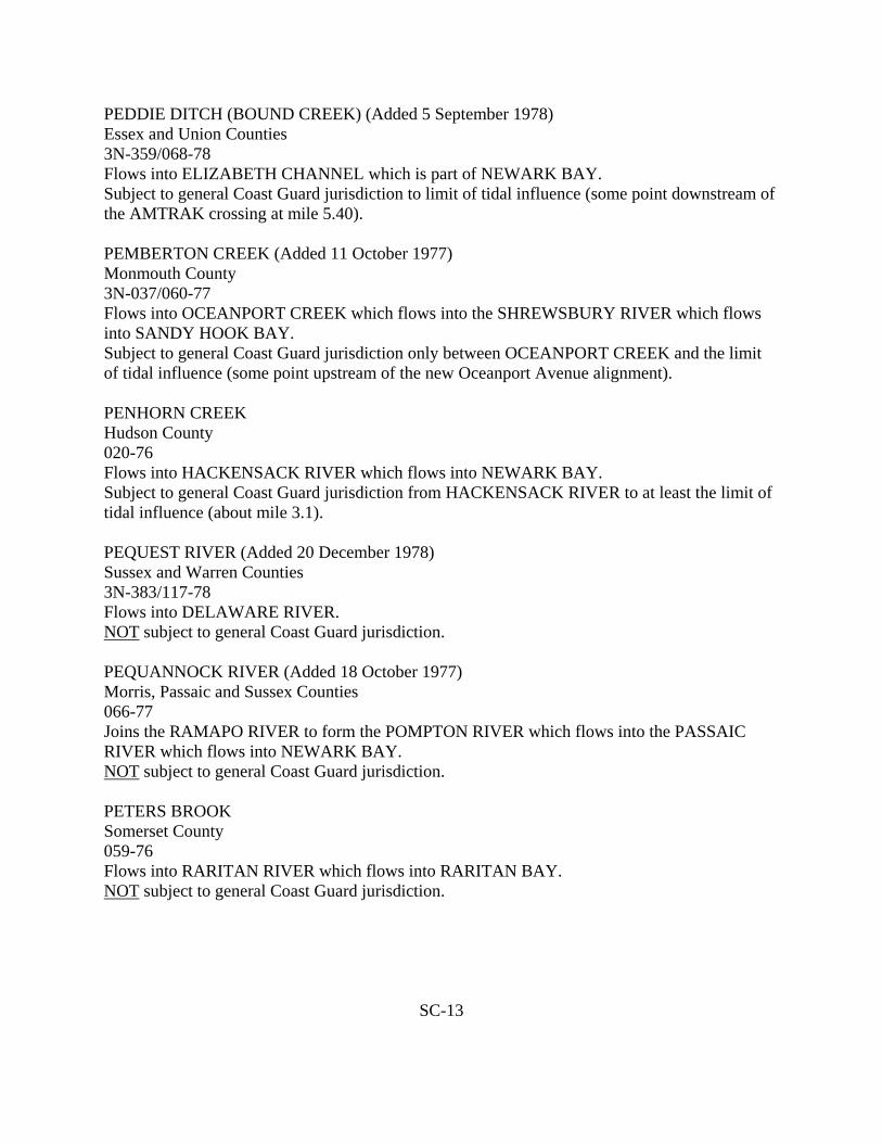
PEDDIE DITCH (BOUND CREEK) (Added 5 September 1978) Essex and Union Counties 3N-359/068-78 Flows into ELIZABETH CHANNEL which is part of NEWARK BAY. Subject to general Coast Guard jurisdiction to limit of tidal influence (some point downstream of the AMTRAK crossing at mile 5.40). PEMBERTON CREEK (Added 11 October 1977) Monmouth County 3N-037/060-77 Flows into OCEANPORT CREEK which flows into the SHREWSBURY RIVER which flows into SANDY HOOK BAY. Subject to general Coast Guard jurisdiction only between OCEANPORT CREEK and the limit of tidal influence (some point upstream of the new Oceanport Avenue alignment). PENHORN CREEK Hudson County 020-76 Flows into HACKENSACK RIVER which flows into NEWARK BAY. Subject to general Coast Guard jurisdiction from HACKENSACK RIVER to at least the limit of tidal influence (about mile 3.1). PEQUEST RIVER (Added 20 December 1978) Sussex and Warren Counties 3N-383/117-78 Flows into DELAWARE RIVER. NOT subject to general Coast Guard jurisdiction. PEQUANNOCK RIVER (Added 18 October 1977) Morris, Passaic and Sussex Counties 066-77 Joins the RAMAPO RIVER to form the POMPTON RIVER which flows into the PASSAIC RIVER which flows into NEWARK BAY. NOT subject to general Coast Guard jurisdiction. PETERS BROOK Somerset County 059-76 Flows into RARITAN RIVER which flows into RARITAN BAY. NOT subject to general Coast Guard jurisdiction.
SC-13
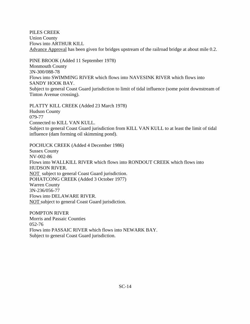
PILES CREEK Union County Flows into ARTHUR KILL Advance Approval has been given for bridges upstream of the railroad bridge at about mile 0.2. PINE BROOK (Added 11 September 1978) Monmouth County 3N-300/088-78 Flows into SWIMMING RIVER which flows into NAVESINK RIVER which flows into SANDY HOOK BAY. Subject to general Coast Guard jurisdiction to limit of tidal influence (some point downstream of Tinton Avenue crossing). PLATTY KILL CREEK (Added 23 March 1978) Hudson County 079-77 Connected to KILL VAN KULL. Subject to general Coast Guard jurisdiction from KILL VAN KULL to at least the limit of tidal influence (dam forming oil skimming pond). POCHUCK CREEK (Added 4 December 1986) Sussex County NV-002-86 Flows into WALLKILL RIVER which flows into RONDOUT CREEK which flows into HUDSON RIVER. NOT subject to general Coast Guard jurisdiction. POHATCONG CREEK (Added 3 October 1977) Warren County 3N-236/056-77 Flows into DELAWARE RIVER. NOT subject to general Coast Guard jurisdiction. POMPTON RIVER Morris and Passaic Counties 052-76 Flows into PASSAIC RIVER which flows into NEWARK BAY. Subject to general Coast Guard jurisdiction.
SC-14

POPLAR BROOK (Added 6 October 1978) Monmouth County 3N-382/093-78 Flows into ATLANTIC OCEAN. Subject to general Coast Guard jurisdiction to limit of tidal influence (about mile 0.0 because of slope of stream bed at mouth of brook). PORICY BROOK (Added 11 September 1978 Monmouth County 3N-324/081-78 Flows into NAVESINK RIVER which follows into SANDY HOOK BAY. Subject to general Coast Guard jurisdiction only between NAVESINK RIVER and limit of tidal influence (spillway at about mile 0.4 which forms PORICY POND). RAHWAY RIVER (Added 22 July 1977) Essex, Middlesex and Union Counties 3N-086/036-77 Flows into ARTHUR KILL. Subject to general Coast Guard jurisdiction to immediate vicinity of St. Georges Avenue crossing. (Jurisdictional status of that crossing in undetermined). There is tidal influence to abut mile 5.5. The jurisdictional status of the RAHWAY RIVER between the limit tidal influence and the immediate vicinity of the St. Georges Avenue crossing is undetermined. RAMAPO RIVER Bergen and Passaic Counties 052-76 Flows into POMPTON RIVER which flows into PASSAIC RIVER which flows into NEWARK BAY. Subject to general Coast Guard jurisdiction only from POMPTON RIVER to mile 2.3 (Pompton Steel Works). RARITAN RIVER (Amended 20 January 1978) 082-77 Flows into RARITAN BAY. Subject to general Coast Guard jurisdiction only from RARITAN BAY to the confluence of the NORTH BRANCH RARITAN RIVER and SOUTH BRANCH RARITAN RIVER (mile 30.2). The branches are NOT subject to general Coast Guard jurisdiction.
SC-15
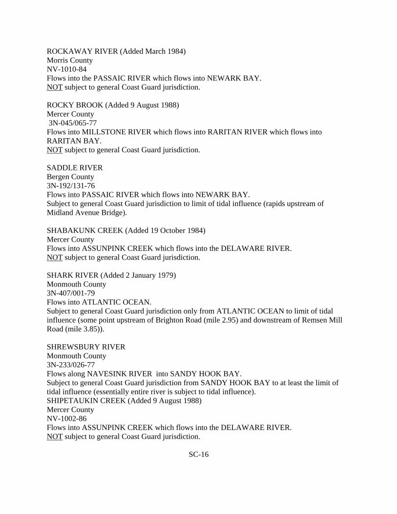
ROCKAWAY RIVER (Added March 1984) Morris County NV-1010-84 Flows into the PASSAIC RIVER which flows into NEWARK BAY. NOT subject to general Coast Guard jurisdiction. ROCKY BROOK (Added 9 August 1988) Mercer County 3N-045/065-77 Flows into MILLSTONE RIVER which flows into RARITAN RIVER which flows into RARITAN BAY. NOT subject to general Coast Guard jurisdiction. SADDLE RIVER Bergen County 3N-192/131-76 Flows into PASSAIC RIVER which flows into NEWARK BAY. Subject to general Coast Guard jurisdiction to limit of tidal influence (rapids upstream of Midland Avenue Bridge). SHABAKUNK CREEK (Added 19 October 1984) Mercer County Flows into ASSUNPINK CREEK which flows into the DELAWARE RIVER. NOT subject to general Coast Guard jurisdiction. SHARK RIVER (Added 2 January 1979) Monmouth County 3N-407/001-79 Flows into ATLANTIC OCEAN. Subject to general Coast Guard jurisdiction only from ATLANTIC OCEAN to limit of tidal influence (some point upstream of Brighton Road (mile 2.95) and downstream of Remsen Mill Road (mile 3.85)). SHREWSBURY RIVER Monmouth County 3N-233/026-77 Flows along NAVESINK RIVER into SANDY HOOK BAY. Subject to general Coast Guard jurisdiction from SANDY HOOK BAY to at least the limit of tidal influence (essentially entire river is subject to tidal influence). SHIPETAUKIN CREEK (Added 9 August 1988) Mercer County NV-1002-86 Flows into ASSUNPINK CREEK which flows into the DELAWARE RIVER. NOT subject to general Coast Guard jurisdiction.
SC-16

SOUTH BEAVER BROOK (Added March 1985) Morris County NV-1010-84 Flows into POMPTON RIVER which flows into the PASSAIC RIVER which flows into NEWARK BAY. NOT subject to general Coast Guard jurisdiction. SOUTH RIVER Middlesex County 3N-198/107-76 Flows into RARITAN RIVER which flows into RARITAN BAY. Subject to general Coast Guard jurisdiction only to limit of tidal influence (dam at DUHERNAL LAKE). See also DUHERNAL LAKE and MANALAPAN BROOK. SPRUCE RUN CREEK (Added 9 August 1988) Hunterdon County NV-1004-86 Flows into SPRUCE RUN RESERVOIR which flows into SOUTH BRANCH RARITAN RIVER which flows into RARITAN RIVER which flows into RARITAN BAY. NOT subject to general Coast Guard jurisdiction. STONY BROOK (Added July 1984) Mercer County NV-1004-84 Flows into the MILLSTONE RIVER which flows into RARITAN RIVER which flows into RARITAN BAY. NOT subject to general Coast Guard jurisdiction. STUMP CREEK (Added 8 September 1978) Middlesex County 3N-335/072-78 Flows into CHEESEQUAKE CREEK which flows into RARITAN BAY. Subject to general Coast Guard jurisdiction from CHEESEQUAKE CREEK to limit of tidal influence (essentially entire creek is subject to tidal influence). SWIMMING RIVER Monmouth County 3N-206/118-76 Flows into NAVESINK RIVER which flows into SANDY HOOK BAY. Subject to general Coast Guard jurisdiction to limit of tidal influence (dam at Swimming River Reservoir).
SC-17

SYLVAN LAKE (Added 20 December 1978) Monmouth County 3N-400/118-78 Drains into ATLANTIC OCEAN. NOT subject to general Coast Guard jurisdiction. TENNENT BROOK (Amended 1 February 1978) Middlesex County 3N-034/034-76 Flows into SOUTH RIVER which flows into RARITAN RIVER which flows into RARITAN BAY. Subject to general Coast Guard jurisdiction to limit of tidal influence (dam at mile 1.2 which forms TENNENT POND). THIRD RIVER Passaic County Flows into PASSAIC RIVER which flows into NEWARK BAY. Advance Approval has been given for bridges from the PASSAIC RIVER to the dam located about 2,320 feet from the mouth of THIRD RIVER. TONYS BROOK (Added February 1985) Essex County NV-1005-84 Flows into the SECOND RIVER. NOT subject to general Coast Guard jurisdiction. TURTLE BROOK (Added 3 March 1977) Middlesex County 3N-226/015-77 Flows into WOODBRIDGE CREEK which flows into ARTHUR KILL. Subject to general Coast Guard jurisdiction to limit of tidal influence (at least 0.3 miles downstream of Blair Road crossing). TURTLE MILL BROOK (Added 11 September 1978) Monmouth County 3N-321/084-78 Flows into BRANCHPORT CREEK which flows into SHREWSBURY RIVER which flows into SANDY HOOK BAY. Subject to general Coast Guard jurisdiction to limit of tidal influence (some point downstream of the Oceanport Avenue crossing).
SC-18

UNNAMED TRIBUTARY (Added 6 June 1977) Monmouth County 028-77 Stream flowing into PARKERS CREEK BRANCH from the north. Subject to general Coast guard jurisdiction to limit of tidal influence (some point downstream of Route 35 crossing). UNNAMED TRIBUTARY (Added 6 June 1977) Monmouth County 027-77 Stream with WAMPUM BROOK as a source and flowing to PARKERS CREEK BRANCH from the south. Subject to general Coast Guard jurisdiction to limit of tidal influence (some point downstream of the Route 35 crossing and upstream of the North Drive crossing). UNNAMED TRIBUTARY (Added 17 October 1977) Hunterdon County 062-77 Stream flowing into the DELAWARE AND RARITAN CANAL at Brookville. NOT subject to general Coast Guard jurisdiction. UNNAMED TRIBUTARY (Added 29 March 1978) Somerset County 3N-352/038-78 Stream flowing into the RARITAN RIVER from north 0.4 miles upstream of the Route 206 crossing NOT subject to general Coast Guard jurisdiction. VALHALLA BRANCH OF CROOKED BROOK (Added March 1985) Morris County NV-1010-84 Flows into the CROOKED BROOK which flows into ROCKAWAY RIVER which flows into PASSAIC RIVER. NOT subject to general Coast Guard jurisdiction. WAACKAACK CREEK (Added 8 September 1978) Monmouth County 3N-327/079-78 Flows into RARITAN BAY. Subject to general Coast Guard jurisdiction to limit of tidal influence (some point upstream of the Monroe Avenue crossing and downstream of the Route 36 crossing (about mile 1.3)).
SC-19

WAGNER CREEK (Added 10 January 1978) Monmouth County 3N-302/007-78 Flows into SANDY HOOK BAY. Subject to general Coast Guard jurisdiction to limit of tidal influence (some point upstream of Center Avenue (600 feet above the mouth) and downstream of West Highland Avenue (1,400 feet above the mouth)). WALLKILL RIVER (Added 2 February 1977) Sussex County 3N-163/082-76 Flows into RONDOUT CREEK which flows into HUDSON RIVER. NOT subject to general Coast Guard jurisdiction. WAMPUM BROOK Monmouth County 3N-217/132-76 Flows into PARKERS CREEK BRANCH which flows into PARKERS CREEK which flows into SHREWSBURY RIVER which flows into SANDY HOOK BAY. NOT subject to general Coast Guard jurisdiction. WANAQUE RIVER ( Added 9 September 1977) Passaic County 3N-150/049-77 Flows from GREENWOOD LAKE to the PEQUANNOCK RIVER. NOT subject to general Coast Guard jurisdiction. WASHINGTON CANAL (Added 17 June 1977) Middlesex County 3N-268/031-77 Flows into the RARITAN RIVER which flows into RARITAN BAY. Subject to general Coast Guard jurisdiction. WEST BROOK Passaic County 3N-150/049-77 Flows into the WANAQUE LAKE. NOT subject to general Coast Guard jurisdiction.
SC-20

WHALE CREEK (Added 8 September 1978) Middlesex and Monmouth Counties 3N-334/075-78 Flows into RARITAN BAY. Subject to general Coast Guard jurisdiction to limit of tidal influence (mile 1.75 which is upstream of the Route 35 crossing and downstream of the New York and Long Branch Railroad crossing). WHALE POND BROOK (Added 6 October 1978) Monmouth County 3N-381/092-78 Flows through a pipe into ATLANTIC OCEAN. Subject to general Coast Guard jurisdiction to limit of tidal influence (waterfall at about mile 0.1). WHIPPANY RIVER (Added 15 April 1975) Morris County Flows into the PASSAIC RIVER NOT subject to general Coast Guard jurisdiction. WILKSON CREEK (Added 8 September 1978) Monmouth County 3N-331/077-78 Flows into MATAWAN CREEK which flows into KEYPORT HARBOR which is part of RARITAN BAY. Subject to general Coast Guard jurisdiction to limit of tidal influence (mile 0.9 which is just downstream of the Garden State Parkway crossing). WOODBRIDGE CREEK (Added 5 July 1978) Middlesex County 3N-349/056-78 Flows into ARTHUR KILL. Subject to general Coast Guard jurisdiction only from ARTHUR KILL to limit of tidal influence (some point upstream of the Reading Railroad crossing (about mile 3.5)). WRECK POND BROOK (Added 17 October 1977) Monmouth County 3N-306/064-77 Flows into WRECK POND which is connected to the ATLANTIC OCEAN through a pipe. Subject to general Coast Guard jurisdiction to limit of tidal influence (some point downstream of the confluence of HANNABRAND BROOK).
SC-21

YARDS CREEK Warren County Flows into PAULINS KILL which flows into DELAWARE RIVER. Federal jurisdiction has been exercised over YARDS CREEK PS Upper and PS Lower Dams.
SC-22

NAMED BODIES OF WATER FIFTH COAST GUARD DISTRICT
ALLOWAY CREEK (Added 25 November 1977) Salem County 3N-242/077-77 Flows into the DELAWARE RIVER. Subject to general Coast Guard Jurisdiction to limit of tidal influence (outlet of ALLOWAY LAKE at about mile 15.7). ASSISCUNK CREEK (Added 18 April 1978) Burlington County 3N-266/047-78 Flows into DELAWARE RIVER. Subject to general Coast Guard jurisdiction to limit of tidal influence (some point between the Skeales Bridge Road (Neck Road) crossing (mile 2.7) and the Old York Road crossing (mile 4.10)). BATSTO RIVER Burlington County 003-76 Flows into MULLICA RIVER which flows into GREAT BAY. Subject to general Coast Guard jurisdiction only from MULLICA RIVER to upstream end of BATSTO POND (3.0). BEAVER BROOK Camden County 3N-212/001-77 Flows into MULLICA RIVER which flows into GREAT BAY. Subject to general Coast Guard jurisdiction to limit of tidal influence (downstream of mile 0.8 which is downstream of New Jersey Turnpike crossing about 0.5 mile west of Black Horse Pike). BEAVERDAM CREEK (Added 6 June 1977) Ocean County 3N-246/025-77 Flows into BARNEGAT BAY. Subject to general Coast Guard jurisdiction only from BARNEGAT BAY to limit of tidal influence (a short distance upstream of a line connecting Cherokee Lane and Meridian Drive).
SC-23

BIDWELLS DITCH (Added 22 August 1986) Cape May County Listed in COMDTPUB P16590.1 “Bridges over Navigable Waters of the United States”. Flows into the DELAWARE BAY. Subject to general Coast Guard jurisdiction. BLACKS CREEK (Added 18 April 1978) Burlington County 3N-262/049-78 Flows into DELAWARE RIVER. Subject to general Coast Guard jurisdiction to limit of tidal influence (some point upstream of the Route 130 crossing (mile 1.5) and downstream of Route 206 crossing (mile 2.3)). BLACKWATER BRANCH (Added 2 August 1988) Cumberland County NV-1004-84 Flows into MAURICE RIVER. NOT subject to general Coast Guard jurisdiction. BOUNDARY CREEK (Added 18 April 1978) Burlington County 3N-262/048-78 Flows into RANCOCAS CREEK. Subject to general Coast Guard jurisdiction to limit of tidal influence (some point downstream of the Creek Road crossing (mile 0.5)). CAPE ISLAND CREEK (Added 2 August 1988) Cape May County NV-1012-84 Flows into CAPE MAY HARBOR. Subject to general Coast Guard jurisdiction in its entirety. CEDAR BRIDGE BRANCH Ocean County 067-76 Flows into METEDECONK RIVER. Subject to general Coast Guard jurisdiction to limit of tidal influence (downstream of Route 70/Rockefeller Memorial Highway Bridge at mile 1.5).
SC-24

CEDAR CREEK (Added 2 August 1988) Cumberland County NV-1011-84 Flows into the DELAWARE RIVER. Subject to general Coast Guard jurisdiction up to approximate mile 5.4, just downstream of the Mulford Avenue crossing. CEDAR CREEK (Added 2 August 1988) Cumberland County Listed in COMDTPUB P16590.1 Flows into DIVIDING CREEK. Subject to general Coast Guard jurisdiction in its entirety. CEDAR SWAMP CREEK Cape May County Flows into TUCKAHOE RIVER which flows into GREAT EGG HARBOR BAY. Advance Approval has been given for bridges upstream of the downstream (north) side of the Tuckahoe Road crossing. CHANDLER’S RUN (Added 2 August 1988) Camden County NV-1005-84 Flows into COOPER RIVER. Subject to general Coast Guard jurisdiction at least to a point upstream of the Route 130 crossing inside a pipe upstream of the Route 130 crossing. CHESTNUT BRANCH (Added 3 March 1978) Gloucester County 3N-365/033-78 Flows into MANTUA CREEK which flows into DELAWARE RIVER. Subject to general Coast Guard jurisdiction to limit of tidal influence (some point downstream of the crossing by Breakneck Road between Barnsboro and Sewell). COHANSEY RIVER Cumberland and Salem Counties 3N-204/113-76 Flows into DELAWARE BAY. Subject to general Coast Guard jurisdiction to limit of tidal influence (between Sunset Lake and Washington Street bridge). COOL RUN Salem County 3N-242/077-77 (Alloway Creek) Flows into ALLOWAY CREEK. NOT subject to general Coast Guard jurisdiction.
SC-25
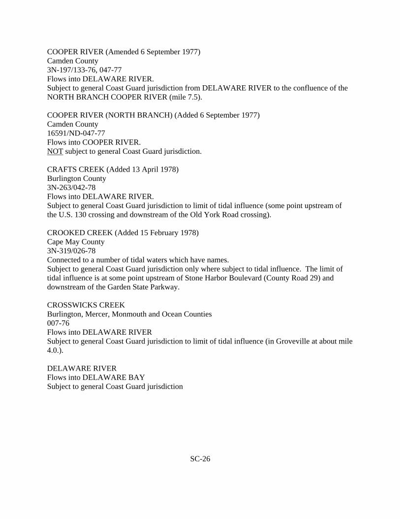
COOPER RIVER (Amended 6 September 1977) Camden County 3N-197/133-76, 047-77 Flows into DELAWARE RIVER. Subject to general Coast Guard jurisdiction from DELAWARE RIVER to the confluence of the NORTH BRANCH COOPER RIVER (mile 7.5). COOPER RIVER (NORTH BRANCH) (Added 6 September 1977) Camden County 16591/ND-047-77 Flows into COOPER RIVER. NOT subject to general Coast Guard jurisdiction. CRAFTS CREEK (Added 13 April 1978) Burlington County 3N-263/042-78 Flows into DELAWARE RIVER. Subject to general Coast Guard jurisdiction to limit of tidal influence (some point upstream of the U.S. 130 crossing and downstream of the Old York Road crossing). CROOKED CREEK (Added 15 February 1978) Cape May County 3N-319/026-78 Connected to a number of tidal waters which have names. Subject to general Coast Guard jurisdiction only where subject to tidal influence. The limit of tidal influence is at some point upstream of Stone Harbor Boulevard (County Road 29) and downstream of the Garden State Parkway. CROSSWICKS CREEK Burlington, Mercer, Monmouth and Ocean Counties 007-76 Flows into DELAWARE RIVER Subject to general Coast Guard jurisdiction to limit of tidal influence (in Groveville at about mile 4.0.). DELAWARE RIVER Flows into DELAWARE BAY Subject to general Coast Guard jurisdiction
SC-26

DIAMOND LAKE/HOSPITALITY BRANCH (Added February 1985) Gloucester County NV-1009-84 DIAMOND LAKE flows into HOSPITALITY BRANCH which is a tributary to GREAT EGG HARBOR RIVER. NOT subject to general Coast Guard jurisdiction. DIAS CREEK (Added 18 August 1977) Cape May County 3N-245/045-77 Flows into DELAWARE BAY. Subject to general Coast Guard jurisdiction to limit of tidal influence. DIAS CREEK has two sources upstream of the Route 47 crossing. The source flowing from a northerly direction is subject to tidal influence to some point upstream of a point about 500 feet upstream of the Potato Island Road (also called Springers Mill Road) crossing and downstream of the Dias Creek Road crossing. The source flowing from a southerly direction is subject to tidal influence to some point upstream of a point about 1,000 feet upstream of the Route 47 crossing and downstream of the Indian Trail Road (Spur 585) crossing. DIVIDING CREEK (Added 2 August 1988) Cumberland County Listed in COMDTPUB P16590.1 “Bridges over Navigable Waters of the United States”. Flows into MAURICE RIVER. Subject to general Coast Guard jurisdiction in its entirety. EAST CREEK (Added 10 March 1977) Cape May County 3N-228/017-77 Flows into DELAWARE BAY. (Some maps show EAST CREEK flowing into ROARING DITCH which flows into DENNIS CREEK which flows into DELAWARE BAY). Subject to general Coast Guard jurisdiction to limit of tidal influence (about mile 4.4 which is downstream of East Creek Mill Road and upstream of Delsea Drive (Route 47)). EDWARDS RUN Gloucester County 022-076 Flows into MANTUA CREEK which flows into DELAWARE RIVER. Subject to general Coast Guard jurisdiction from MANUTA CREEK to at least limit of tidal influence (upstream of New Jersey Turnpike crossing - immediately upstream of NJTPK bridge at mile 1.4).
SC-27

FORTESCUE CREEK (Added 27 June 1977) Cumberland County 3N-240/034-77 Flows into DELAWARE BAY. Subject to general Coast Guard jurisdiction. GAME CREEK (Added 17 August 1981) Salem County 3N-304/028-78 Flows into SALEM RIVER NOT subject to general Coast Guard jurisdiction. GARRETTS DITCH (Added 8 December 1977) Atlantic County 3N-237/042-77 Connected to ABSECON BAY which is connected to the ATLANTIC OCEAN. Subject to general Coast Guard jurisdiction. GOOSE CREEK (Amended 28 April 1976) Ocean County 130-76, 128-76 Flows into BARNEGAT BAY. Subject to general Coast Guard jurisdiction from BARNEGAT BAY to at least the limit of tidal influence (upstream (west) of Fischer Boulevard). Tidal canal connected to the south side of GOOSE CREEK and ending at Wood Street near Beachview Drive is subject to general Coast Guard jurisdiction. (The tidal storm sewer running under Wood Street, Beachview Drive and Fischer Boulevard from the end of this canal is not a culvert and not subject to general Coast Guard jurisdiction). GREAT EGG HARBOR RIVER (Amended 21 February 1979) Atlantic, Camden and Gloucester Counties 3N-241/039-77 Flows into GREAT EGG HARBOR NOT subject to general Coast Guard jurisdiction upstream of the point where vessels were loaded at the Weymouth Furnace (some point downstream of the County Road 40 crossing) to carry material to Mays Landing. The limit of tidal influence is at the dam near Mays Landing which forms Lake Lenape. The jurisdictional status of the GREAT EGG HARBOR RIVER between the limit of tidal influence and Weymouth is undetermined.
SC-28

HAYNES CREEK Burlington County 3N-170/085-76 Flows into SOUTHWEST BRANCH RANCOCAS CREEK which flows into SOUTH BRANCH RANCOCAS CREEK with flows into RANCOCAS CREEK with flows into DELAWARE RIVER. Subject to general Coast Guard jurisdiction from SOUTHWEST BRANCH RANCOCAS CREEK to at least the dam at Oliphants Mills. HOLMES CREEK (Added 15 February 1978) Cape May County 3N-319/027-78 Flows into HOLMES COVE which is part of GREAT SOUND. Subject to general Coast Guard jurisdiction only between GREAT SOUND and limit of tidal influence (some point upstream of the Garden State Parkway at mile 0.8 and downstream of Route 9 (Seashore Road) at mile 1.1). INTRACOASTAL WATERWAY (Added 2 November 1978) Ocean, Atlantic and Cape May Counties 101-78 Connected to ATLANTIC OCEAN. Subject to general Coast Guard jurisdiction. JEFFREYS CREEK Ocean County 3N-199/122-76 Flows into TOMS RIVER which flows into BARNEGAT BAY. Subject to general Coast Guard jurisdiction to limit of tidal influence (downstream of Point Pleasant Road crossing). KENDLES RUN (Added 7 March 1979) Burlington County 3N-407/009-79 Flows into RANCOCAS CREEK which flows into DELAWARE RIVER. Subject to general Coast Guard jurisdiction to limit of tidal influence (about mile 0.2 which is downstream (north) of the Creek Road crossing). KETTLE CREEK (Added 31 January 1977) Ocean County 3N-218/008-77 Plows into BARNEGAT BAY. Subject to general Coast Guard jurisdiction to limit of tidal influence (downstream of IRISADO LAKE).
SC-29

LAKE MARTHA (Added 27 June 1977) Gloucester County 3N-290/033-77 Flows into the DELAWARE RIVER. Subject to general Coast Guard jurisdiction from the DELAWARE RIVER to at least the limit of tidal influence. LAUREL RUN (Added 13 July 1978) Burlington County 3N-259/063-78 Flows into RANCOCAS CREEK which flows into DELAWARE RIVER. Subject to general Coast Guard jurisdiction to limit of tidal influence (some point upstream of mile 0.25 and downstream of the Creek Road crossing at mile 0.52). LITTLE CREEK (Added 15 October 1987) Burlington County NV-0120-76 Flows into SOUTHWEST BRANCH OF RANCOCAS CREEK which flows into SOUTH BRANCH OF RANCOCAS CREEK which flows into RANCOCAS CREEK which flows into DELAWARE RIVER. Subject to general Coast Guard jurisdiction at least to limit of tidal influence (some point between the mouth at mile 0.0 and Eayrestown Road crossing at approximately mile 0.7). LITTLE EASE RUN (Added 9 August 1988) Gloucester County 3N-369/040-78 Flows into STILL RUN which flows into MAURICE RIVER which flows into DELAWARE BAY. NOT subject to general Coast Guard jurisdiction. LONG BRANCH CREEK (Added 2 August 1988) Salem County NV-1003-86 Flows through SILVER LAKE MEADOW into ALLOWAY CREEK. NOT subject to general Coast Guard jurisdiction. LONG SWAMP CREEK (Added 6 October 1978) Ocean County 3N-398/094-78 Flows into TOMS RIVER which flows into BARNEGAT BAY Subject to general Coast Guard jurisdiction to limit of tidal influence (about mile 0.15 which is downstream of Washington Street crossing).
SC-30

MANASQUAN RIVER (Added 11 January 1978) Monmouth and Ocean Counties 3N-305/008-78 Flows into the ATLANTIC OCEAN. Subject to general Coast Guard jurisdiction from the ATLANTIC OCEAN to the point where boats were loaded at the Howell Furnace which is in the restored village in Allaire State Park (about mile 8.7). NOT subject to general Coast Guard jurisdiction upstream of that point. MANTUA CREEK (Amended 3 March 1978) Gloucester County 3N-365/032-78 Flows into DELAWARE RIVER. Subject to general Coast Guard jurisdiction from DELAWARE RIVER to limit of tidal influence (some point upstream of the Mantua Avenue crossing (mile 8.5) and downstream of the Glassboro Road crossing (mile 10.8)). NOT subject to general Coast Guard jurisdiction upstream of a point immediately downstream of the Glassboro Road crossing. MASONS CREEK (Added 2 June 1977) Burlington County 3N-238/023-77 Flows into SOUTH BRANCH RANCOCAS CREEK which flows into RANCOCAS CREEK which flows into the DELAWARE RIVER. Subject to general Coast Guard jurisdiction to limit of tidal influence (about 1,500 feet downstream of Marne Highway crossing). MAURICE RIVER (Amended 29 March 1978) Cumberland, Gloucester and Salem Counties Flows into DELAWARE BAY. Subject to general Coast Guard jurisdiction only from DELAWARE BAY to the dam forming UNION LAKE. MENANTICO CREEK Atlantic and Cumberland Counties 019-76 Flows into MAURICE RIVER which flows into DELAWARE BAY. Subject to general Coast Guard jurisdiction to at least the limit of tidal influence (about 0.7 miles south of the New Jersey Route 49).
SC-31

METEDECONK RIVER Monmouth and Ocean Counties 063-76 Flows into BARNEGAT BAY. Subject to general Coast Guard jurisdiction to limit of tidal influence (between Route 70 and the confluence of the North and South Branches). MILL CREEK Burlington County 025-76 Flows into RANCOCAS CREEK which flows into DELAWARE RIVER. Subject to general Coast Guard jurisdiction from RANCOCAS CREEK to at least the limit of tidal influence (about mile 1.8). MILL CREEK (Added 22 September 1978) Ocean County 3N-395/089-78 Flows into LITTLE EGG HARBOR which is connected to ATLANTIC OCEAN. Subject to general Coast Guard jurisdiction to limit of tidal influence (just downstream of the Jennings Road crossing at about mile 2.6). MONONGAHELA BROOK (Added 3 March 1978) Gloucester County 3N-365/034-78 Flows into MANTUA CREEK which flows into DELAWARE RIVER. Subject to general Coast Guard jurisdiction to limit of tidal influence (some point downstream of the Marian Avenue crossing near Wenonah). MUD DIGGER DITCH (Added 3 March 1978) Salem County 3N-304/029-78 Connected to SALEM RIVER through two underground pipes about 24 inches in diameter and 200 to 300 feet long. The pipes pass through a pumping station and have tide gates at their SALEM RIVER ends. NOT subject to general Coast Guard jurisdiction. MULLICA RIVER Atlantic, Burlington and Camden Counties 008-76 Flows into GREAT BAY Subject to general Coast Guard jurisdiction to limit of tidal influence (about mile 22.3 which is about 1.1 miles upstream of Route 542 bridge at Pleasant Mills).
SC-32
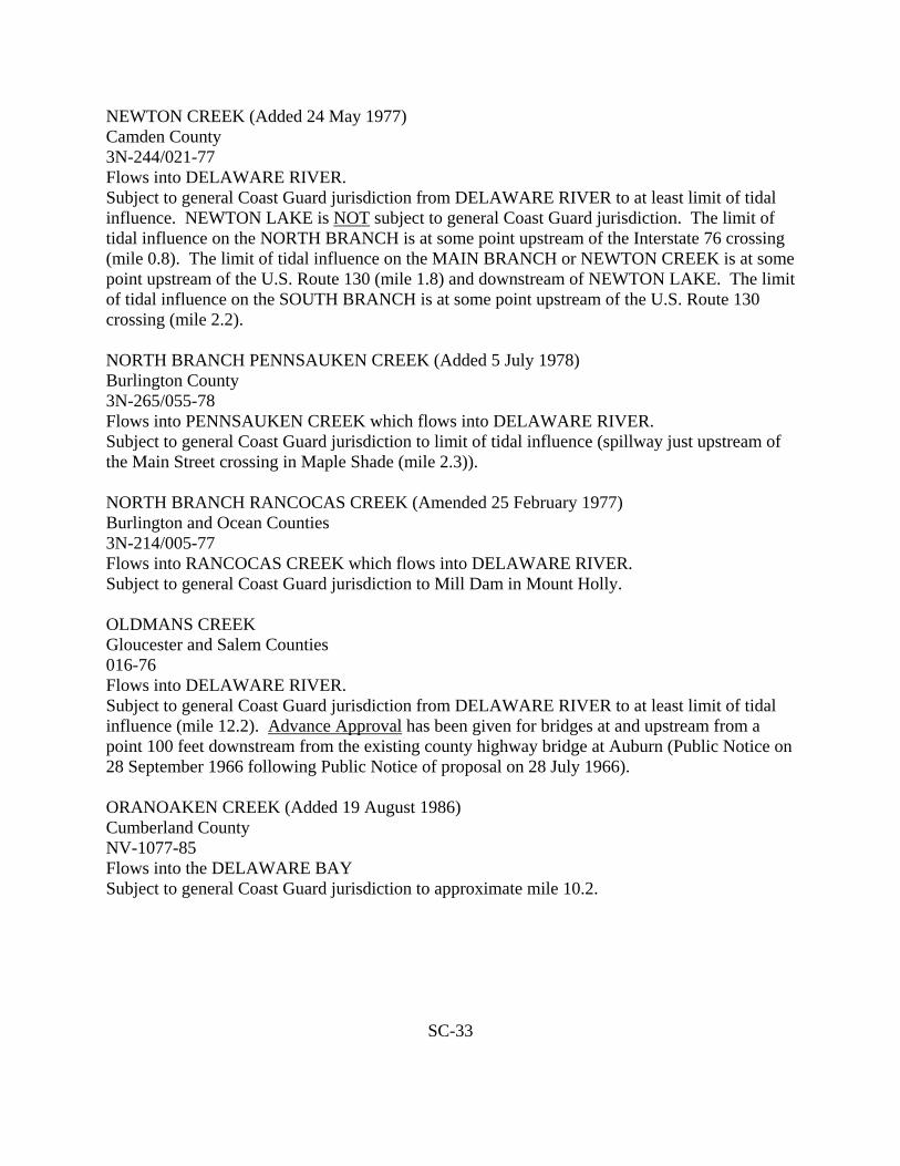
NEWTON CREEK (Added 24 May 1977) Camden County 3N-244/021-77 Flows into DELAWARE RIVER. Subject to general Coast Guard jurisdiction from DELAWARE RIVER to at least limit of tidal influence. NEWTON LAKE is NOT subject to general Coast Guard jurisdiction. The limit of tidal influence on the NORTH BRANCH is at some point upstream of the Interstate 76 crossing (mile 0.8). The limit of tidal influence on the MAIN BRANCH or NEWTON CREEK is at some point upstream of the U.S. Route 130 (mile 1.8) and downstream of NEWTON LAKE. The limit of tidal influence on the SOUTH BRANCH is at some point upstream of the U.S. Route 130 crossing (mile 2.2). NORTH BRANCH PENNSAUKEN CREEK (Added 5 July 1978) Burlington County 3N-265/055-78 Flows into PENNSAUKEN CREEK which flows into DELAWARE RIVER. Subject to general Coast Guard jurisdiction to limit of tidal influence (spillway just upstream of the Main Street crossing in Maple Shade (mile 2.3)). NORTH BRANCH RANCOCAS CREEK (Amended 25 February 1977) Burlington and Ocean Counties 3N-214/005-77 Flows into RANCOCAS CREEK which flows into DELAWARE RIVER. Subject to general Coast Guard jurisdiction to Mill Dam in Mount Holly. OLDMANS CREEK Gloucester and Salem Counties 016-76 Flows into DELAWARE RIVER. Subject to general Coast Guard jurisdiction from DELAWARE RIVER to at least limit of tidal influence (mile 12.2). Advance Approval has been given for bridges at and upstream from a point 100 feet downstream from the existing county highway bridge at Auburn (Public Notice on 28 September 1966 following Public Notice of proposal on 28 July 1966). ORANOAKEN CREEK (Added 19 August 1986) Cumberland County NV-1077-85 Flows into the DELAWARE BAY Subject to general Coast Guard jurisdiction to approximate mile 10.2.
SC-33
OSWEGO RIVER (Added 12 July 1978) Burlington and Ocean Counties 3N-264/062-78 Joins WEST BRANCH WADING RIVER to form WADING RIVER which flows into MULLICA RIVER which flows into GREAT BAY. Subject to general Coast Guard jurisdiction to limit of tidal influence (spillway just downstream of the Chatsworth Road crossing (about mile 0.4)). OYSTER CREEK (Added 10 December 1974) Cumberland County 3274 Flows into DELAWARE BAY. Subject to general Coast Guard jurisdiction in its entirely. PARKERS CREEK (Added 31 January 1977 and Amended 31 May 1977) Burlington County 3N-221/009-77 Flows into RANCOCAS CREEK which flows into DELAWARE RIVER. Subject to general Coast Guard jurisdiction to limit of tidal influence (downstream of New Jersey Turnpike crossing at about mile 1.4 and upstream of Centerton Road crossing at about mile 0.7). PATCONG CREEK (Added 13 April 1978) Atlantic County 3N-339/043-78 Flows into GREAT EGG HARBOR BAY. Subject to general Coast Guard jurisdiction to limit of tidal influence (spillway forming BARGAINTOWN POND). PENNSAUKEN CREEK (Added 15 March 1977) Burlington and Camden Counties 3N-224/011-77 Flows into DELAWARE RIVER. Subject to general Coast Guard jurisdiction. PENNSAUKEN CREEK (NORTH BRANCH) Burlington County ND-055-78 Flows into PENNSAUKEN CREEK which flows into the DELAWARE RIVER. Subject to general Coast Guard jurisdiction to limit of tidal influence (spillway just upstream of the Main Street crossing in Maple Shade - approximate mile 2.3).
SC-34

PENNSAUKEN CREEK (SOUTH BRANCH) (Added 15 March 1977) Burlington and Camden Counties 3N-224/011-77 Flows into PENNSAUKEN CREEK which flows into DELAWARE RIVER. Subject to general Coast Guard jurisdiction from PENNSAUKEN CREEK to at least the limit of tidal influence (upstream of mile 0.6). PENROSE CANAL (NJ Intracoastal Waterway LATERAL EXTENSION) Atlantic County ND-101-78 Flows into BEACH THOROFARE Subject to general Coast Guard jurisdiction in its entirety. POLHEMUS BRANCH (Added 24 May 1977) Ocean County 3N-248/020-77 Flows into KETTLE CREEK which flows into BARNEGAT BAY. Subject to general Coast Guard jurisdiction to limit of tidal influence (some point downstream of Hooper Avenue (Route 549)). RACCOON CREEK (Amended 29 March 1978) Gloucester County 3N-057/022-76 Flows into DELAWARE RIVER. Subject to general Coast Guard jurisdiction only from DELAWARE RIVER to some point upstream of Russell Mill Road (mile 9.9) and downstream of Tomlin Road (mile 11.2). RANCOCAS CREEK Burlington County Flows into DELAWARE RIVER. Subject to general Coast Guard jurisdiction. See also NORTH BRANCH RANCOCAS CREEK, SOUTHWEST BRANCH RANCOCAS CREEK AND SOUTH BRANCH RANCOCAS CREEK. REED BRANCH OF THE MAURICE RIVER (Added February 1985) Gloucester County NV-1009-84 Flows into the SHELL RUN NOT subject to general Coast Guard jurisdiction.
SC-35
SALEM CANAL (Added 3 March 1978) Salem County 3N-304/031-78 Connects SALEM RIVER to DELAWARE RIVER Subject to general Coast Guard jurisdiction. SALEM RIVER (Added 3 March 1978) Salem County 3N-304/028-78 Flows into DELAWARE RIVER. Subject to general Coast Guard jurisdiction from DELAWARE RIVER to the limit of past use for substantial interstate or foreign commerce (vicinity of Sharptown). NOT subject to general Coast Guard jurisdiction upstream of the Route 45 crossing near Woodstown. SAWMILL CREEK Ocean County 066-76 Flows into MANASQUAN RIVER which flows into ATLANTIC OCEAN. Subject to general Coast Guard jurisdiction only to limit of tidal influence (downstream of Herbertsville Road crossing for NORTH BRANCH - upstream of Herbertsville Road crossing for SOUTH BRANCH). SILVER BAY (Added 21 January 1977) Ocean County 129-76 Flows into BARNEGAT BAY. SILVER BAY and two unnamed tributaries flowing under Fischer Boulevard are subject to general Coast Guard jurisdiction from BARNEGAT BAY to at least the limit of tidal influence (west of Fischer Boulevard for the tributaries). SOUTH BRANCH RANCOCAS CREEK (Amended 5 September 1978) Burlington County 3N-170, 267/085-76,070-78 Flows into RANCOCAS CREEK which flows into DELAWARE RIVER. Subject to general Coast Guard jurisdiction from RANCOCAS CREEK to limit of past use for substantial interstate or foreign commerce (floating of logs and lumber from as far upstream of Vincentown at a point just downstream of the Route 643 crossing). SOUTH CREEK (Added 9 August 1988) Ocean County Flows into WESTECUNK CREEK which flows into LITTLE EGG HARBOR. Subject to general Coast Guard jurisdiction to limit of tidal influence (essentially the entire creek is tidal).
SC-36

SOUTHWEST BRANCH RANCOCAS CREEK Burlington County 3N-170/085-76 Flows into SOUTH BRANCH RANCOCAS CREEK which flows into RANCOCAS CREEK which flows into DELAWARE RIVER. Subject to general Coast Guard jurisdiction from RANCOCAS CREEK to a least the confluence of HAYNES CREEK. STILL RUN (Added 9 August 1988) Gloucester County 3N-369/040-78 Flows into MAURICE RIVER which flows into DELAWARE BAY. NOT subject to general Coast Guard jurisdiction. STOCKTON BROOK Monmouth County 3N-180/101-76 Flows into STOCKTON LAKE which flows into WATSON CREEK which flows into MANASQUAN RIVER which flows into ATLANTIC OCEAN. Subject to general Coast Guard jurisdiction from STOCKTON LAKE to at least the limit of tidal influence (upstream of New York and Long Branch Railroad crossing). STOCKTON LAKE Monmouth County 3N-180/101-76 Flows into WATSON CREEK which flows into MANASQUAN RIVER which flows into ATLANTIC OCEAN. Subject to general coast Guard jurisdiction. STOW CREEK (Added 17 August 1981) Cumberland and Salem Counties NV-1002-84 Flows into the DELAWARE BAY. Subject to general Coast Guard jurisdiction to limit of tidal influence at some point between the Buckhorn Road bridge, mile 17.2 and the Jerico Road bridge, mile 18.5. SWEDE RUN (Added 22 September 1978) Burlington County 3N-388/090-78 Flows into DREDGE HARBOR which is connected to DELAWARE RIVER. Subject to general Coast Guard jurisdiction to limit of tidal influence (about mile 1).
SC-37
THE GLIMMER GLASS (Added 26 December 1979) Monmouth County 3N-305/012-79 Flows into MANASQUAN RIVER which flows into ATLANTIC OCEAN. Subject to general Coast Guard jurisdiction from MANASQUAN RIVER to limit of tidal influence (essentially all THE GLIMMER GLASS is subject to tidal influence). THREE MOUTHS CREEK (Added 10 December 1974) Cumberland County 3247 Flows into the DELAWARE BAY. Subject to general Coast Guard jurisdiction in its entirety. TILBURY SLUICEWAY DITCH (Added 3 March 1978) Salem County 3N-304/029-78 Connected to SALEM RIVER through two underground pipes about 24 inches in diameter and 200 to 300 feet long. The pipes pass through a pumping station and have tide gates at their SALEM RIVER ends. NOT subject to general Coast Guard jurisdiction. TOM’S RIVER (Added 18 June 1976) Monmouth and Ocean Counties 3260/ND-051-76 Flows into BARNEGAT BAY Subject to general Coast Guard jurisdiction to limit of tidal influence at mile 7.2 (about 1.0 miles north-northwest of the Route 37 crossing). TOMS RIVER - JAKES’ BRANCH TOMS RIVER - NORTH BRANCH TOMS RIVER - SOUTH BRANCH All listed in CG425-1 “Bridges over Navigable Waters of the Untied States”. Subject to general Coast Guard jurisdiction. UNNAMED STREAM including LAKE BAGALORE (Added 29 March 1978) Stream including LAKE BASGALORE and flowing into RACCOON CREEK from the south just upstream of the New Jersey Turnpike crossing. Gloucester County ND-039-78 Flows into RACCOON CREEK which flows into DELAWARE RIVER which flows into DELAWARE BAY. Subject to general Coast Guard jurisdiction to limit of tidal influence (some point downstream of the Russel Mill Road crossing at about mile 0.7).
SC-38

UNNAMED STREAM TRIBUTARY TO HOLMES CREEK (Added 29 August 1978) Stream flowing under the Garden State Parkway about 0.7 mile north of Stone Harbor Boulevard and flowing into HOLMES CREEK from the south at about mile 0.5. Cape May County 067-78. Flows into HOLMES CREEK which flows into HOLMES COVE which is a part of GREAT SOUND. Subject to general Coast Guard jurisdiction to limit of tidal influence (some point about 200 to 300 feet downstream of the Garden State Parkway). UNNAMED TRIBUTARY TO PENNSAUKEN CREEK (Amended 9 August 1978) Waterway along the south side of Remington Avenue joining PENNSAUKEN CREEK at about mile 2.5. Camden County ND-044-78 Flows into PENNSAUKEN CREEK which flows into DELAWARE RIVER which flows into DELAWARE BAY. Subject to general Coast Guard jurisdiction to limit of tidal influence (some point near the southerly side of the Route 73 crossing (about mile 0.1)). URIAH BRANCH (Added 21 February 1980) Ocean County ND-002-80 Flows into WESTECUNK CREEK which flows into LITTLE EGG HARBOR which connects to ATLANTIC OCEAN. Subject to general Coast Guard jurisdiction to limit of tidal influence (upstream side of Route 9 crossing (mile 0.3) which is downstream of Railroad Avenue Crossing). WADING RIVER (Added 12 July 1978) Burlington County 3N-264/060-78 Flows into MULLICA RIVER which flows into GREAT BAY. Subject to general Coast Guard jurisdiction. See also OSWEGO RIVER and WEST BRANCH WADING RIVER. WATSON CREEK Monmouth County 3N-180/101-76 Flows into the MANASQUAN RIVER which flows into ATLANTIC OCEAN. Subject to general Coast Guard jurisdiction.
SC-39

WEST BRANCH WADING RIVER (Added 12 July 1978) Burlington County 3N-264/061-78 Joins OSWEGO RIVER to form WADING RIVER which flows into MULLICA RIVER which flows into GREAT BAY. Subject to general Coast Guard jurisdiction to limit of tidal influence (about mile 0.7). WEST CREEK (Added 29 July 1976) Cumberland and Cape May Counties ND-076-76 Flows south from its source in NEW JERSEY PINE BARRENS which flows into DELAWARE BAY. Subject to general Coast Guard jurisdiction to limit of tidal influence (Paper Mill Road bridge at mile 6.7). WESTECUNK CREEK (Added 21 February 1980) Ocean County ND-001-80 Flows into LITTLE EGG HARBOR which connects to ATLANTIC OCEAN. Subject to general Coast Guard jurisdiction at least to limit of tidal influence (some point upstream of confluence of URIAH BRANCH). WRANGEL BROOK (Added 6 October 1978) Ocean County 3N-397/095-78 Flows into TOMS RIVER which flows into BARNEGAT BAY. Subject to general Coast Guard jurisdiction to limit of tidal influence (some point downstream of the South Hampton Road crossing at about mile 1.3).
SC-40

APPENDIX D
SECTION 101 TO 105 OF 1978 FEDERAL HIGHWAY ACT
PUBLIC LAW 95-9599 [H.R. 11733]; Nov. 6, 1978
SURFACE TRANSPORTATION ASSISTANCE
ACT OF 1978
For Legislative History of Act, see p. 6575
An Act to authorize appropriations for the construction of certain highways in accordance with Title 23 of the Untied States Code, for highway safety, for mass transportation in urban and in rural areas, and for other purposes.
Be it enacted by the Senate and House of Representatives of the Untied States of America in Congress assembled, That this Act may be cited as the “Surface Transportation Assistance Act of 1978:.
TITLE I
SHORT TITLE
Sec. 101. This title may be cited as the “Federal-Aid Highway Act of 1978”.
REVISION OF AUTHORIZATION FOR APPROPRIATIONS FOR THE INTERSTATE SYSTEM. Sec. 102. (a) Subsection (b) of section 108 of the Federal-Aid Highway Act of 1956, as amended by striking out “the additional sum of $3,625,000,000 for the fiscal year ending September 20, 1980,” and all that follows down through the period at the end of the sentence and by inserting in lieu thereof the following: “the additional sum of $3,250,000,000 for the fiscal year ending September 30, 1980, the addition sum of $3,500,000,000 for the fiscal year ending September 30, 1981, the additional sum of $3,500,000,000 for the fiscal year ending September 30, 1982, the additional sum of $3,200,000,000 for the fiscal year ending September 20, 1983, the additional sum of $3,625,000,000 for the fiscal year ending September 20, 1984, the additional sum of $3,625,000,000 for the fiscal year ending September 30, 1985, the additional sum of $3,625,000,000 for the fiscal year ending September 20, 1986, the additional sum of $3,625,000,000 for the fiscal year ending September 30, 1987, the additional sum of $3,625,000,000 for the fiscal year ending September 30, 1988, the additional sum of $3,625,000,000 for the fiscal year ending September 30, 1989, and the additional sumo of $3,625,000,000 for the fiscal year ending September 30, 1990”. (b) Subsection (b) of section 108 of the Federal-Aid Highway Act of 1956, as amended, is further amended by adding at the end thereof the following “ “Beginning with funds authorized to be appropriated for fiscal year 1980, no such funds shall be available for projects to expand or clear zones immediately adjacent to the paved roadway of routes designed priority to February, 1967”.
92 STAT. 2690
SD-1
Surface Transportation Assistance Act of 1978. 23USC101 note. Federal Aid Highway Act of 1978 23USC101 note.
23 USC 101 note

AUTHORIZATIONS OF USE OF COST ESTIMATES FOR APPORTIONMENT OF INTERSTATE FUNDS
Sec. 103. The Secretary of Transportation shall apportion for the fiscal year ending September 30, 1980, the sums authorized to be appropriated for such periods by section 108(b) of the Federal-Aid Highway Act of 1956, as amended, for expenditures on the national System of Interstate and Defense Highways, using the apportionment factors contained in revised table 5 of Committee print 95-49 of the Committee on Public Works and Transportation of the House of Representatives.
P.L. 95-599 LAWS OF 95th CONG. - 2nd SESS. Nov. 6
HIGHWAY AUTHORIZATION
Sec. 104 (a) For the purpose of carrying out the provisions of Title 23, United States Code, the following sums are hereby authorized to be appropriated: (1) For the Federal-aid primary system in rural areas, including the extensions of the Federal-aid primary system in urban areas and the priority primary routes, out of the Highway Trust Fund, $1,550,000,000 for the fiscal year ending September 30, 1979, $1,700,000,000 for the fiscal year ending September 30, 1980, $1,800,000,000 for the fiscal year ending September 30, 1981 and $1,500,000,000 for the fiscal year ending September 30, 1982. For the Federal-aid secondary system in rural areas, out of the Highway Trust Fund $500,000,000 for the fiscal year ending September 30, 1979, $550,000,000 for the fiscal year ending September 20, 1980, $600,000,000 for the fiscal year ending September 30, 1981 and $400,000,000 for the fiscal year ending September 30, 1982. (2) For the Federal-aid urban system, out of the Highway Trust Fund, $800,000,000 per fiscal year for each of the fiscal years ending September 30, 1979, September 30, 1980, September 30, 1981 and September 30, 1982. (3) For the forest highways, out of the Highway Trust Fund,$33,000,000 per fiscal year for each of the fiscal years ending September 30, 1979, September 30, 1980, September 30, 1981 and September 30, 1982. (4) For public lands highways, out of the Highway Trust fund. $16,000,000 per fiscal year for each of the fiscal years ending September 30, 1979, September 30, 1980, September 30, 1981 and September 30, 1982.
92 STAT. 2690
SD-2
23 USC 104 note
Appropriation authorization.

P.L. 95-599 LAWS OF 95th CONG. - 2nd SESS. Nov. 6
HIGHWAY AUTHORIZATION
(5) For forest development roads and trails. $140,000,000 per fiscal year for each of the fiscal years ending September 30, 1979, September 30, 1980, September 30, 1981 and September 30, 1982. (6) For public lands development roads and trails $10,000,000 per fiscal year for each of the fiscal years ending September 30, 1979, September 30, 1980, September 20, 1981 and September 30, 1982. (7) For park roads and trails $30,000,000 per fiscal year for each of the fiscal years ending September 30, 1979, September 30, 1980, September 30, 1981 and September 30, 1982. (8) For parkways $45,000,000 per fiscal year for each of the fiscal years ending September 30, 1979, September 20, 1980, September 30, 1981 and September 30, 1982. The entire cost of any parkway project on any Federal-aid system paid under the authorization contained in this paragraph shall be paid from the Highway Trust Fund. (9) For Indian reservation roads and bridges $83,000,000 per fiscal year for each of the fiscal years ending September 30, 1979, September 30, 1980, September 30, 1981 and September 30, 19982. (10) For economic growth center development highways under section 143 Title 23. United States Code, out of the Highway Trust Fund $50,000,000 per fiscal year for each of the fiscal years ending September 30, 1979, September 30, 1980, September 30, 1981 and September 30, 1982. (11) For necessary administrative expenses in carrying out section 131 and section 136 of Title 23. united States Code $1,5000,000 per fiscal year for each of the fiscal years ending September 30, 1979, September 30, 1980, September 30, 1981 and September 30, 1982. (12) For carrying out section 215(a) of Title 23, United States Code
(A) for the Virgin Islands, not to exceed $5,000,000 per fiscal year for each of the fiscal years ending September 30, 1979, September 30, 1980, September 30, 1981 and September 30, 1982. (B) for Guam, not to exceed $5,000,000 per fiscal year for each of the fiscal years ending September 30, 1979, September 30, 1980, September 30, 1981 and September 30, 1982. (C) for American Samoa, not to exceed $1,000,000 per fiscal year for each of the fiscal years ending September 30, 1979, September 30, 1980, September 30, 1981 and September 30, 1982.
92 STAT. 2691
SD-3
23 USC 215 note.

P.L. 95-599 LAWS OF 95th CONG. - 2nd SESS. Nov. 6
Sums authorized by this paragraph shall be available for obligation at the beginning of the period for which authorized in the same manner and to the same extent as if such sums were apportioned under Chapter 1 of Title 23. United States Code.
(13) For the Commonwealth of the Northern Mariana Island, not to exceed $1,000,000 per fiscal year for each of the fiscal years ending September 30, 1979, September 30, 1980, September 30, 1981 and September 30, 1982. Sums authorized by this paragraph shall be expended in the same manner as sums authorized to carry out Section 215 of Title 23, United States Code. Sums authorized by this parapet shall be available for obligation at the beginning of the period for which authorized in the same manner and to the same extent as if such sums were apportioned under Chapter 1 of Title 23, United States Code. (14) For the Northeast corridor demonstration program under Section 322 of Title 23, United States Code. $45,000,000 for the fiscal year ending September 30, 1979 and $40,000,000 for the fiscal year ending September 30, 1980. (15) For the Great River Road $10,000,000 per fiscal year for each of the fiscal years ending September 30, 1979, September 30, 1980, September 30, 1981 and September 30, 1982, for construction or reconstruction of roads not on a Federal-aid highway system; and out of the highway Trust Fund, $25,000,000 per fiscal year for each of the fiscal years ending September 30, 1979, September 20, 1980, September 30, 1981 and September 30, 1982, for construction or reconstruction of roads on a Federal- aid highway system. (16) For control of outdoor advertising under Section 131 of Title 23, United States Code $30,000,000 per fiscal year for each of the fiscal years ending September 30, 1979, September 30, 1980, September 30, 1981 and September 30, 1982. (17) For safer off-system roads under Section 219 of Title 23, United States Code, $200,000,000 per fiscal year for each of the fiscal years ending September 30, 1979, September 30, 1980, September 30, 1981 and September 30, 1982. (18) For access highways under Section 155 of Title 23, United States Code, $15,000,000 per fiscal year for each of the fiscal years ending September 30, 1979, September 30, 1980, September 30, 1981 and September 30, 1982.
92 STAT. 2691
SD-4
23 USC 101 et seq.

P.L. 95-599 LAWS OF 95th CONG. - 2nd SESS. Nov. 6
(b)(1) For each of the fiscal years 1980, 1981, 1982 and 19883, no State, including the State of Alaska, Shall receive less than one-half of 1 per centum of the total apportionment for the Interstate System under Section 104(b)(5) of Title 23, United States Code. Whenever amounts made available under subsection for the Interstate System in any State exceed the estimated cost of completing that State’s portion of the Interstate System and exceed the estimated cost of necessary resurfacing, restoration and rehabilitation of the interstate System within such State, the excess amount shall be eligible for expenditure for those purposes for which funds apportioned under paragraphs (1), (2), (6) of such Section 104(b) may be expended and shall also be available for expenditure to carry out Section 152 of Title 23, United States Code. In order to carry out this subsection and Section 158 of the Federal-Aid Highway Act of 1973, there are authorized to be appropriated, out of the Highway Trust Fund, not to exceed $125,000,000 per fiscal year for each of the fiscal years ending September 30, 1980, September 30, 1981, September 30, 1982 and September 30, 1983. (2) In addition to funds otherwise authorized, $85,000,000, out of the Highway Trust Fund, is hereby authorized for the purpose of completing routes designated under the urban high density traffic program prior to May 5, 1976. Such sums shall be in addition to sums previously authorized. (c) In the case of priority primary routes, $125,000,000 per fiscal year of the sums authorized for each of the fiscal years ending September 30, 1979, September 30, 1980, September 30, 1981 and September 30, 1982 by subsection (a) (1) of this section for such routes shall not be apportioned. Such $125,000,000 of each such authorized sum shall be available for obligation on the date of apportionment of funds for each such fiscal year, in the same manner and to the same extent as the sums apportioned on such date, except that such $125,000,000 shall be available for obligation at the discretion of the Secretary of Transportation only for projects of unusually high cost or which require long periods of time for their construction. Any part of such $125,000,000 not obligated by such Secretary on or before the last day of the fiscal year for which authorized shall be immediately apportioned in the same manner as funds apportioned for the next succeeding fiscal year for primary system routes, and available for obligation for the same periods as such apportionment.
92 STAT. 2692
SD-5
87 Stat. 278.
P.L. 95-599 LAWS OF 95th CONG. - 2nd SESS. Nov. 6
(d)(1) Twenty per centum or more of the apportionment for each fiscal year to each State of the sum authorized in paragraph (1) of subsection (a) of this section for the Federal-aid primary system (including extensions in urban areas and priority primary routes) for such fiscal year shall be obligated in such State for projects for the resurfacing, restoration and rehabilitation of highways on such system. (2) Twenty per centum or more of the apportionment for each fiscal year to each State of the sum authorized in paragraph (1) of subsection (a) of this section for Federal-aid secondary system for such fiscal year shall be obligated in such State for projects for the resurfacing, restoration and rehabilitation of highways on such system.
INTERSTATE SYSTEM RESURFACING
SEC. 105. In addition to any other funds authorized to be appropriated, there is authorized to be appropriated, out of the Highway Trust Fund, not to exceed $175,000,000 per fiscal year for each of the fiscal years ending September 30, 1980 and September 30, 1981 and not to exceed $275,000,000 per fiscal year for each of the fiscal years end September 30, 1982 and September 30, 1983. Such sums shall be obligated for projects for resurfacing, restoring and rehabilitating those lanes on the Interstate System which have been in use for more than five years and which are not on toll roads, except that where at State certifies to the Secretary that any part of such sums are excess to the needs of such State for resurfacing, restoring or rehabilitating Interstate System lanes and the Secretary accepts such certification, such State may transfer sums apportioned to it under section 104(b) (5) (B) to its apportionment under section 104 (b) (1). Such sums may also be obligated for projects for resurfacing, restoring and rehabilitating lanes in use for more than five years on a toll road which has been designated as a part of the Interstate System if any agreement satisfactory to the Secretary of Transportation has been reached with the State highway department and any public authority with jurisdiction over such toll road prior to the approval of such project that the toll road will become free to the public upon the collection of tolls sufficient to liquidate the cost of the toll road or any bonds outstanding at the time constituting a valid lien against it, and the cost of maintenance and operation and debt service during the period of toll collections. The agreement referred to in the preceding sentence shall contain a provision requiring that if, for any reasons, a toll road receiving Federal assistance under this section does not become free to the public upon collection of sufficient tolls,
92 STAT. 2693
SD-6
Appropriation authorization.
Excess funds, certification and transfer.
Toll roads, agreement.
Federal assistance, repayment

P.L. 95-599 LAWS OF 95th CONG. - 2nd SESS. Nov. 6
as specified in the preceding sentence. Federal funds used for projects on such toll road pursuant to this section shall be repaid to the Federal Treasury.
DEFINITIONS
SEC. 106. (a) The definition of “construction” in section 101(a) of title 23 of the United States Code is amended by adding at the end thereof the following new sentence: “the term also includes capital improvements which directly facilitate an effective vehicle weight enforcement program, such as scales (fixed and portable), scale pits, scale installation and scale houses”. (b)(1) The definition of “forest road or trail” in section 101(a)of Title 23 of the United States Code is amended to read as follows: “The term ‘forest or trail’ means a road or trail wholly or partly within, or adjacent to, and serving the National Forest system and which is necessary for the protection administration and utilization of the National Forest system and the use and development of its resources”. (2) The definition of “forest development road and trails” in section 101(a) of Title 23 of the United States Code is amended to read as follows: “The term ‘forest development roads and trails’ means a forest road or trail under the jurisdiction of the Forest Service”. (3) The definition of “forest highway” in section 101(a) of Title 23 of the United States Code is amended to read as follows: “The term ‘forest highway’ means a forest road under the jurisdiction of and maintained by, a public authority and open to public travel”. (4) Section 101(a) of Title 23, United States Code, is amended by adding after the definition of the term “Federal-aid highways” the following new definition: “The term ‘highway safety improvement project’ means a project which corrects or improves high hazard locations, eliminates roadside
SD-7
APPENDIX E
2000 CENSUS OF POPULATION AND HOUSING GEOGRAPHIC IDENTIFICATION CODE SCHEME
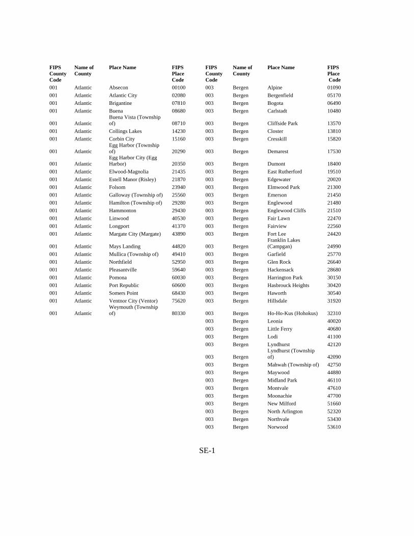
FIPS County Code
Name of County
Place Name FIPS Place Code
FIPS County Code
Name of County
Place Name FIPS Place Code
001 Atlantic Absecon 00100 003 Bergen Alpine 01090 001 Atlantic Atlantic City 02080 003 Bergen Bergenfield 05170 001 Atlantic Brigantine 07810 003 Bergen Bogota 06490 001 Atlantic Buena 08680 003 Bergen Carlstadt 10480
001 Atlantic Buena Vista (Township of) 08710
003 Bergen Cliffside Park 13570
001 Atlantic Collings Lakes 14230 003 Bergen Closter 13810 001 Atlantic Corbin City 15160 003 Bergen Cresskill 15820
001 Atlantic Egg Harbor (Township of) 20290
003 Bergen Demarest 17530
001 Atlantic Egg Harbor City (Egg Harbor) 20350
003 Bergen Dumont 18400
001 Atlantic Elwood-Magnolia 21435 003 Bergen East Rutherford 19510 001 Atlantic Estell Manor (Risley) 21870 003 Bergen Edgewater 20020 001 Atlantic Folsom 23940 003 Bergen Elmwood Park 21300 001 Atlantic Galloway (Township of) 25560 003 Bergen Emerson 21450 001 Atlantic Hamilton (Township of) 29280 003 Bergen Englewood 21480 001 Atlantic Hammonton 29430 003 Bergen Englewood Cliffs 21510 001 Atlantic Linwood 40530 003 Bergen Fair Lawn 22470 001 Atlantic Longport 41370 003 Bergen Fairview 22560 001 Atlantic Margate City (Margate) 43890 003 Bergen Fort Lee 24420
001 Atlantic Mays Landing 44820
003 Bergen Franklin Lakes (Campgan) 24990
001 Atlantic Mullica (Township of) 49410 003 Bergen Garfield 25770 001 Atlantic Northfield 52950 003 Bergen Glen Rock 26640 001 Atlantic Pleasantville 59640 003 Bergen Hackensack 28680 001 Atlantic Pomona 60030 003 Bergen Harrington Park 30150 001 Atlantic Port Republic 60600 003 Bergen Hasbrouck Heights 30420 001 Atlantic Somers Point 68430 003 Bergen Haworth 30540 001 Atlantic Ventnor City (Ventor) 75620 003 Bergen Hillsdale 31920
001 Atlantic Weymouth (Township of) 80330
003 Bergen Ho-Ho-Kus (Hohokus) 32310
003 Bergen Leonia 40020 003 Bergen Little Ferry 40680 003 Bergen Lodi 41100 003 Bergen Lyndhurst 42120
003 Bergen Lyndhurst (Township of) 42090
003 Bergen Mahwah (Township of) 42750 003 Bergen Maywood 44880 003 Bergen Midland Park 46110 003 Bergen Montvale 47610 003 Bergen Moonachie 47700 003 Bergen New Milford 51660 003 Bergen North Arlington 52320 003 Bergen Northvale 53430 003 Bergen Norwood 53610
SE-1
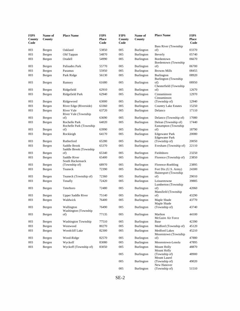
FIPS County Code
Name of County
Place Name FIPS Place Code
FIPS County Code
Name of County
Place Name FIPS Place Code
003 Bergen Oakland 53850
005 Burlington Bass River (Township of) 03370
003 Bergen Old Tappan 54870 005 Burlington Beverly 05740 003 Bergen Oradell 54990 005 Burlington Bordentown 06670
003 Bergen Palisades Park 55770
005 Burlington Bordentown (Township of) 06700
003 Bergen Paramus 55950 005 Burlington Browns Mills 08455 003 Bergen Park Ridge 56130 005 Burlington Burlington 08920
003 Bergen Ramsey 61680
005 Burlington Burlington (Township of) 08950
003 Bergen Ridgefield 62910
005 Burlington Chesterfield (Township of) 12670
003 Bergen Ridgefield Park 62940 005 Burlington Cinnaminson 12970
003 Bergen Ridgewood 63000
005 Burlington Cinnaminson (Township of) 12940
003 Bergen River Edge (Riverside) 63360 005 Burlington Country Lake Estates 15250 003 Bergen River Vale 63720 005 Burlington Delanco 17110
003 Bergen River Vale (Township of) 63690
005 Burlington Delanco (Township of) 17080
003 Bergen Rochelle Park 64020 005 Burlington Delran (Township of) 17440
003 Bergen Rochelle Park (Township of) 63990
005 Burlington
Eastampton (Township of) 18790
003 Bergen Rockleigh 64170 005 Burlington Edgewater Park 20080
003 Bergen Rutherford 65280
005 Burlington Edgewater Park (Township of) 20050
003 Bergen Saddle Brook 65370 005 Burlington Evesham (Township of) 22110
003 Bergen Saddle Brook (Township of) 65340
005 Burlington Fieldsboro 23250
003 Bergen Saddle River 65400 005 Burlington Florence (Township of) 23850
003 Bergen South Hackensack (Township of) 68970
005 Burlington Florence-Roebling 23895
003 Bergen Teaneck 72390 005 Burlington Fort Dix (U.S. Army) 24300
003 Bergen Teaneck (Township of) 72360
005 Burlington Hainesport (Township of) 29010
003 Bergen Tenafly 72420 005 Burlington Leisuretowne 39885
003 Bergen Teterboro 72480
005 Burlington Lumberton (Township of) 42060
003 Bergen Upper Saddle River 75140
005 Burlington Mansfield (Township of) 43290
003 Bergen Waldwick 76400 005 Burlington Maple Shade 43770
003 Bergen Wallington 76490
005 Burlington Maple Shade (Township of) 43740
003 Bergen Washington (Township of) 77135
005 Burlington Marlton 44100
003 Bergen Washington Township 77510
005 Burlington McGuire Air Force Base 42390
003 Bergen Westwood 80270 005 Burlington Medford (Township of) 45120 003 Bergen Woodcliff Lake 82300 005 Burlington Medford Lakes 45210
003 Bergen Wood-Ridge 82570
005 Burlington Moorestown (Township of) 47880
003 Bergen Wyckoff 83080 005 Burlington Moorestown-Lenola 47895 003 Bergen Wyckoff (Township of) 83050 005 Burlington Mount Holly 48870
005 Burlington Mount Holly (Township of) 48900
005 Burlington
Mount Laurel (Township of) 49020
005 Burlington
New Hanover (Township of) 51510
SE-2

FIPS County Code
Name of County
Place Name FIPS Place Code
FIPS County Code
Name of County
Place Name FIPS Place Code
005 Burlington North Hanover (Township of) 53070
007 Camden Ashland 01990
005 Burlington Palmyra 55800 007 Camden Audubon 02200 005 Burlington Pemberton 57480 007 Camden Audubon Park 02230
005 Burlington Pemberton (Township of) 57510
007 Camden Barclay-Kingston 02905
005 Burlington Pemberton Heights 57540 007 Camden Barrington 03250
005 Burlington Presidential Lakes Estates 60840
007 Camden Bellmawr 04750
005 Burlington Ramblewood 61650 007 Camden Berlin 05440 005 Burlington Riverside 63540 007 Camden Berlin (Township of) 05470 005 Burlington Riverside (Township of) 63510 007 Camden Blackwood 06040 005 Burlington Riverton 63660 007 Camden Brooklawn 08170 005 Burlington Shamong (Township of) 66810 007 Camden Camden 10000
005 Burlington Southampton (Township of) 68610
007 Camden Cherry Hill 12310
005 Burlington Springfield (Township of) 69990
007 Camden
Cherry Hill (Township of) 12280
005 Burlington Tabernacle (Township of) 72060
007 Camden Cherry Hill Mall 12385
005 Burlington Washington (Township of) 77150
007 Camden Chesilhurst 12550
005 Burlington Westampton (Township of) 78200
007 Camden Clementon 13420
005 Burlington Willingboro (Levittown) 81470 007 Camden Collingswood 14260
005 Burlington Willingboro (Township of) 81440
007 Camden Echelon 19900
005 Burlington Woodland (Township of) 82420 007 Camden Erlton-Ellisburg 21645 005 Burlington Wrightstown 82960 007 Camden Gibbsboro 26070 007 Camden Glendora 26520
007 Camden Gloucester (Township of) 26760
007 Camden
Gloucester City (Gloucester) 26820
007 Camden Golden Triangle 26902 007 Camden Greentree 27995 007 Camden Haddon (Township of) 28740 007 Camden Haddon Heights 28800 007 Camden Haddonfield 28770 007 Camden Hi-Nella (Hi Nella) 32220 007 Camden Laurel Springs 39210 007 Camden Lawnside 39420 007 Camden Lindenwold 40440 007 Camden Magnolia 42630 007 Camden Merchantville 45510 007 Camden Mount Ephraim 48750 007 Camden Oaklyn 53880
007 Camden Pennsauken (Pensauken) 57690
007 Camden
Pennsauken (Township of) 57660
007 Camden
Pine Hill (Clementon Heights) 58770
007 Camden Pine Valley 58920 007 Camden Runnemede 65160
SE-3

FIPS County Code
Name of County
Place Name FIPS Place Code
FIPS County Code
Name of County
Place Name FIPS Place Code
007 Camden Somerdale 68340 009 Cape May Avalon 02320 007 Camden Springdale 69900 009 Cape May Cape May 10270 007 Camden Stratford 71220 009 Cape May Cape May Court House 10300 007 Camden Tavistock 72240 009 Cape May Cape May Point 10330 007 Camden Voorhees (Township of) 76220 009 Cape May Dennis (Township of) 17560 007 Camden Waterford (Township of) 77630 009 Cape May Diamond Beach 17815 007 Camden Winslow (Township of) 81740 009 Cape May Erma 21660 007 Camden Woodlynne 82450 009 Cape May Lower (Township of) 41610 009 Cape May Middle (Township of) 45810 009 Cape May North Cape May 52650 009 Cape May North Wildwood 53490 009 Cape May Ocean City 54360 009 Cape May Rio Grande 63180 009 Cape May Sea Isle City 66390 009 Cape May Stone Harbor 71010 009 Cape May Strathmere 71250 009 Cape May Upper (Township of) 74810 009 Cape May Villas 76010 009 Cape May West Cape May 78530 009 Cape May West Wildwood 80210 009 Cape May Whitesboro-Burleigh 80855 009 Cape May Wildwood 81170 009 Cape May Wildwood Crest 81200 009 Cape May Woodbine 81890
SE-4
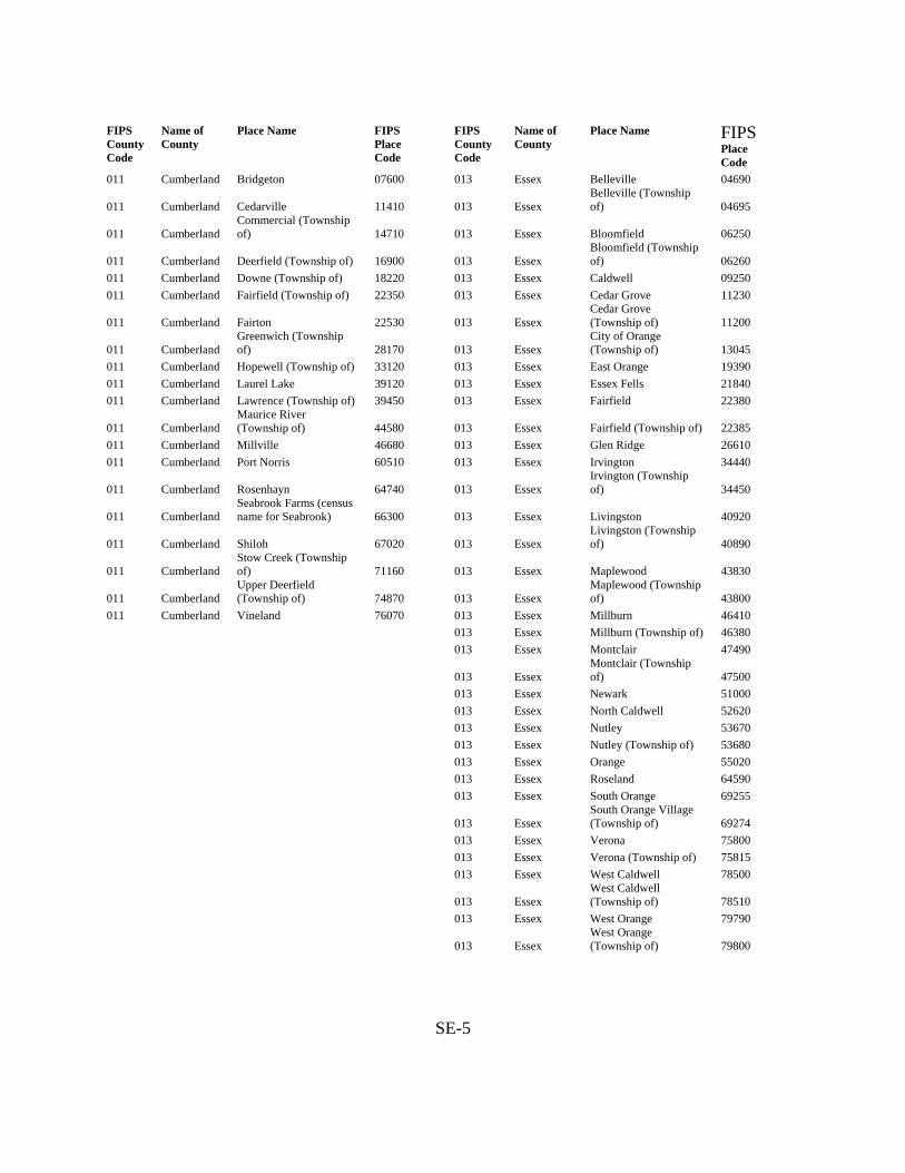
FIPS County Code
Name of County
Place Name FIPS Place Code
FIPS County Code
Name of County
Place Name FIPS Place Code
011 Cumberland Bridgeton 07600 013 Essex Belleville 04690
011 Cumberland Cedarville 11410
013 Essex Belleville (Township of) 04695
011 Cumberland Commercial (Township of) 14710
013 Essex Bloomfield 06250
011 Cumberland Deerfield (Township of) 16900
013 Essex Bloomfield (Township of) 06260
011 Cumberland Downe (Township of) 18220 013 Essex Caldwell 09250 011 Cumberland Fairfield (Township of) 22350 013 Essex Cedar Grove 11230
011 Cumberland Fairton 22530
013 Essex Cedar Grove (Township of) 11200
011 Cumberland Greenwich (Township of) 28170
013 Essex
City of Orange (Township of) 13045
011 Cumberland Hopewell (Township of) 33120 013 Essex East Orange 19390 011 Cumberland Laurel Lake 39120 013 Essex Essex Fells 21840 011 Cumberland Lawrence (Township of) 39450 013 Essex Fairfield 22380
011 Cumberland Maurice River (Township of) 44580
013 Essex Fairfield (Township of) 22385
011 Cumberland Millville 46680 013 Essex Glen Ridge 26610 011 Cumberland Port Norris 60510 013 Essex Irvington 34440
011 Cumberland Rosenhayn 64740
013 Essex Irvington (Township of) 34450
011 Cumberland Seabrook Farms (census name for Seabrook) 66300
013 Essex Livingston 40920
011 Cumberland Shiloh 67020
013 Essex Livingston (Township of) 40890
011 Cumberland Stow Creek (Township of) 71160
013 Essex Maplewood 43830
011 Cumberland Upper Deerfield (Township of) 74870
013 Essex
Maplewood (Township of) 43800
011 Cumberland Vineland 76070 013 Essex Millburn 46410 013 Essex Millburn (Township of) 46380 013 Essex Montclair 47490
013 Essex Montclair (Township of) 47500
013 Essex Newark 51000 013 Essex North Caldwell 52620 013 Essex Nutley 53670 013 Essex Nutley (Township of) 53680 013 Essex Orange 55020 013 Essex Roseland 64590 013 Essex South Orange 69255
013 Essex South Orange Village (Township of) 69274
013 Essex Verona 75800 013 Essex Verona (Township of) 75815 013 Essex West Caldwell 78500
013 Essex West Caldwell (Township of) 78510
013 Essex West Orange 79790
013 Essex West Orange (Township of) 79800
SE-5

FIPS County Code
Name of County
Place Name FIPS Place Code
FIPS County Code
Name of County
Place Name FIPS Place Code
015 Gloucester Beckett 04400 017 Hudson Bayonne 03580 015 Gloucester Clayton 13360 017 Hudson East Newark 19360 015 Gloucester Deptford (Township of) 17710 017 Hudson Guttenberg 28650
015 Gloucester East Greenwich (Township of) 19180
017 Hudson Harrison 30210
015 Gloucester Elk (Township of) 21060 017 Hudson Hoboken 32250 015 Gloucester Franklin (Township of) 24840 017 Hudson Jersey City 36000
015 Gloucester Gibbstown (Township name Greenwich) 26100
017 Hudson Kearny 36510
015 Gloucester Glassboro 26340 017 Hudson North Bergen 52440
015 Gloucester Greenwich (Township of) 28185
017 Hudson
North Bergen (Township of) 52470
015 Gloucester Harrison (Township of) 30180 017 Hudson Secaucus 66570 015 Gloucester Logan (Township of) 41160 017 Hudson Union City 74630 015 Gloucester Mantua (Township of) 43440 017 Hudson Weehawken 77960
015 Gloucester Monroe (Township of) 47250
017 Hudson Weehawken (Township of) 77930
015 Gloucester Mullica Hill 49440 017 Hudson West New York 79610 015 Gloucester National Park 49680
015 Gloucester Newfield 51390
015 Gloucester Oak Valley 54060
015 Gloucester Paulsboro 57150
015 Gloucester Pitman 59070
015 Gloucester South Harrison (Township of) 69030
015 Gloucester Swedesboro 71850
015 Gloucester Turnersville 74270
015 Gloucester Victory Lakes 75920
015 Gloucester Washington (Township of) 77180
015 Gloucester Wenonah 78110
015 Gloucester West Deptford (Township of) 78800
015 Gloucester Westville 80120
015 Gloucester Williamstown 81380
015 Gloucester Woodbury 82120
015 Gloucester Woodbury Heights 82180
015 Gloucester Woolwich (Township of) 82840
SE-6

FIPS County Code
Name of County
Place Name FIPS Place Code
FIPS County Code
Name of County
Place Name FIPS Place Code
019 Hunterdon Alexandria (Township of) 00550
021 Mercer
East Windsor (Township of) 19780
019 Hunterdon Annandale 01480 021 Mercer Ewing 22180
019 Hunterdon Bethlehem (Township of) 05650
021 Mercer Ewing (Township of) 22185
019 Hunterdon Bloomsbury 06370
021 Mercer Hamilton (Township of) 29310
019 Hunterdon Califon 09280 021 Mercer Hightstown 31620 019 Hunterdon Clinton 13720 021 Mercer Hopewell 33150
019 Hunterdon Clinton (Township of) 13750
021 Mercer Hopewell (Township of) 33180
019 Hunterdon Delaware (Township of) 17170
021 Mercer Lawrence (Township of) 39510
019 Hunterdon East Amwell (Township of) 18820
021 Mercer Lawrenceville 39570
019 Hunterdon Flemington 23700
021 Mercer Mercerville-Hamilton Square 45495
019 Hunterdon Franklin (Township of) 24870 021 Mercer Pennington 57600 019 Hunterdon Frenchtown 25350 021 Mercer Princeton 60900
019 Hunterdon Glen Gardner 26550
021 Mercer Princeton (Township of) 60915
019 Hunterdon Hampton 29460 021 Mercer Princeton Junction 60960 019 Hunterdon High Bridge 31320 021 Mercer Princeton North 60990 019 Hunterdon Holland (Township of) 32460 021 Mercer Trenton 74000 019 Hunterdon Kingwood (Township of) 37065 021 Mercer Twin Rivers 74330
019 Hunterdon Lambertville 38610
021 Mercer Washington (Township of) 77210
019 Hunterdon Lebanon 39630
021 Mercer West Windsor (Township of) 80240
019 Hunterdon Lebanon (Township of) 39660 021 Mercer White Horse 80630 019 Hunterdon Milford 46260 021 Mercer Yardville-Groveville 83185 019 Hunterdon Raritan (Township of) 61920
019 Hunterdon Readington (Township of) 62250
019 Hunterdon Stockton 70980
019 Hunterdon Tewksbury (Township of) 72510
019 Hunterdon Union (Township of) 74420
019 Hunterdon West Amwell (Township of) 78230
019 Hunterdon White House Station (White Station) 80720
SE-7

FIPS County Code
Name of County
Place Name FIPS Place Code
FIPS County Code
Name of County
Place Name FIPS Place Code
023 Middlesex Avenel 02350 023 Middlesex South Amboy 68550
023 Middlesex Brownville 08492
023 Middlesex South Brunswick (Township of) 68790
023 Middlesex Carteret 10750 023 Middlesex South Plainfield 69390 023 Middlesex Clearbrook Park 13399 023 Middlesex South River 69420 023 Middlesex Cliffwood Beach 13630 023 Middlesex Spotswood 69810 023 Middlesex Colonia 14380 023 Middlesex Whittingham 81042 023 Middlesex Concordia 14758 023 Middlesex Woodbridge 81950
023 Middlesex Cranbury 15520
023 Middlesex Woodbridge (Township of) 82000
023 Middlesex Cranbury (Township of) 15550
023 Middlesex Dayton 16630
023 Middlesex Dunellen 18490
023 Middlesex East Brunswick 18970
023 Middlesex East Brunswick (Township of) 19000
023 Middlesex Edison 20260
023 Middlesex Edison (Township of) 20230
023 Middlesex Fords 24030
023 Middlesex Heathcote 30738
023 Middlesex Helmetta 30840
023 Middlesex Highland Park 31470
023 Middlesex Iselin 34470
023 Middlesex Jamesburg 34890
023 Middlesex Kendall Park 36660
023 Middlesex Kingston 36930
023 Middlesex Laurence Harbor 39360
023 Middlesex Madison Park 42540
023 Middlesex Metuchen 45690
023 Middlesex Middlesex 45900
023 Middlesex Milltown 46620
023 Middlesex Monmouth Junction 47190
023 Middlesex Monroe (Township of) 47280
023 Middlesex New Brunswick 51210
023 Middlesex North Brunswick (Township of) 52560
023 Middlesex North Brunswick Township 52605
023 Middlesex Old Bridge 54690
023 Middlesex Old Bridge (Township of) 54705
023 Middlesex Perth Amboy 58200
023 Middlesex Piscataway (Township of) 59010
023 Middlesex Plainsboro (Township of) 59280
023 Middlesex Plainsboro Center 59285
023 Middlesex Port Reading 60540
023 Middlesex Princeton Meadows 60975
023 Middlesex Rossmoor 64865
023 Middlesex Sayreville 65790
023 Middlesex Sewaren 66720
023 Middlesex Society Hill 68304
SE-8

FIPS County Code
Name of County
Place Name FIPS Place Code
FIPS County Code
Name of County
Place Name FIPS Place Code
025 Monmouth Aberdeen (Township of) 00070 025 Monmouth Monmouth Beach 47130 025 Monmouth Allenhurst 00730 025 Monmouth Morganville 48030 025 Monmouth Allentown 00760 025 Monmouth Navesink 49740 025 Monmouth Allenwood 00790 025 Monmouth Neptune (Township of) 49890 025 Monmouth Asbury Park 01960 025 Monmouth Neptune City 49920 025 Monmouth Atlantic Highlands 02110 025 Monmouth North Middletown 53205 025 Monmouth Avon-by-the-Sea 02440 025 Monmouth Oakhurst 53790 025 Monmouth Belford 04600 025 Monmouth Ocean (Township of) 54270 025 Monmouth Belmar 04930 025 Monmouth Ocean Grove 54480 025 Monmouth Bradley Beach 06970 025 Monmouth Oceanport 54570 025 Monmouth Brielle 07750 025 Monmouth Port Monmouth 60360 025 Monmouth Cliffwood Beach 13630 025 Monmouth Ramtown 61725
025 Monmouth Colts Neck (Township of) 14560
025 Monmouth Red Bank 62430
025 Monmouth Deal 16660 025 Monmouth Robertsville 63900
025 Monmouth East Freehold 19150
025 Monmouth Roosevelt (Jersey Homesteads) 64410
025 Monmouth Eatontown 19840 025 Monmouth Rumson 65130 025 Monmouth Englishtown 21570 025 Monmouth Sea Bright 66240 025 Monmouth Fair Haven 22440 025 Monmouth Sea Girt 66330 025 Monmouth Fairview 22740 025 Monmouth Shark River Hills 66840 025 Monmouth Farmingdale 22950 025 Monmouth Shrewsbury 67350
025 Monmouth Freehold 25200
025 Monmouth Shrewsbury (Township of) 67365
025 Monmouth Freehold (Township of) 25230
025 Monmouth South Belmar (Lake Como) 68670
025 Monmouth Hazlet (Township of) 30690
025 Monmouth Spring Lake (Spring Lake Beach) 70110
025 Monmouth Highlands 31500 025 Monmouth Spring Lake Heights 70140 025 Monmouth Holmdel (Township of) 32640 025 Monmouth Strathmore 71280
025 Monmouth Howell (Township of) 33300
025 Monmouth Tinton Falls (New Shrewsbury) 73020
025 Monmouth Interlaken 34200 025 Monmouth Union Beach 74540
025 Monmouth Keansburg 36480
025 Monmouth Upper Freehold (Township of) 74900
025 Monmouth Keyport 36810 025 Monmouth Wall (Township of) 76460 025 Monmouth Leonardo 39990 025 Monmouth Wanamassa 76700 025 Monmouth Lincroft 40320 025 Monmouth West Belmar 78350 025 Monmouth Little Silver 40770 025 Monmouth West Freehold 79100 025 Monmouth Loch Arbour 41010 025 Monmouth West Long Branch 79310 025 Monmouth Long Branch 41310 025 Monmouth Yorketown 83245
025 Monmouth Manalapan (Township of) 42990
025 Monmouth Manasquan 43050
025 Monmouth Marlboro (Township of) 44070
025 Monmouth Matawan 44520
025 Monmouth Middletown (Township of) 45990
025 Monmouth Millstone (Township of) 46560
SE-9
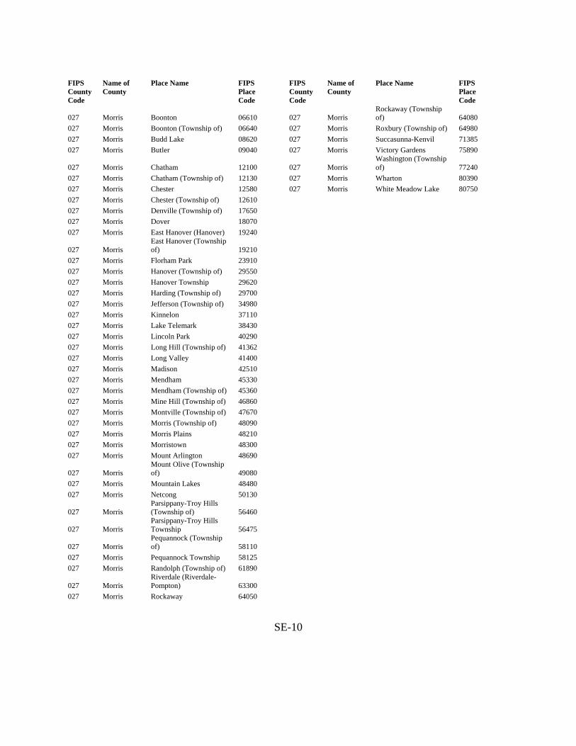
FIPS County Code
Name of County
Place Name FIPS Place Code
FIPS County Code
Name of County
Place Name FIPS Place Code
027 Morris Boonton 06610
027 Morris Rockaway (Township of) 64080
027 Morris Boonton (Township of) 06640 027 Morris Roxbury (Township of) 64980 027 Morris Budd Lake 08620 027 Morris Succasunna-Kenvil 71385 027 Morris Butler 09040 027 Morris Victory Gardens 75890
027 Morris Chatham 12100
027 Morris Washington (Township of) 77240
027 Morris Chatham (Township of) 12130 027 Morris Wharton 80390 027 Morris Chester 12580 027 Morris White Meadow Lake 80750 027 Morris Chester (Township of) 12610
027 Morris Denville (Township of) 17650
027 Morris Dover 18070
027 Morris East Hanover (Hanover) 19240
027 Morris East Hanover (Township of) 19210
027 Morris Florham Park 23910
027 Morris Hanover (Township of) 29550
027 Morris Hanover Township 29620
027 Morris Harding (Township of) 29700
027 Morris Jefferson (Township of) 34980
027 Morris Kinnelon 37110
027 Morris Lake Telemark 38430
027 Morris Lincoln Park 40290
027 Morris Long Hill (Township of) 41362
027 Morris Long Valley 41400
027 Morris Madison 42510
027 Morris Mendham 45330
027 Morris Mendham (Township of) 45360
027 Morris Mine Hill (Township of) 46860
027 Morris Montville (Township of) 47670
027 Morris Morris (Township of) 48090
027 Morris Morris Plains 48210
027 Morris Morristown 48300
027 Morris Mount Arlington 48690
027 Morris Mount Olive (Township of) 49080
027 Morris Mountain Lakes 48480
027 Morris Netcong 50130
027 Morris Parsippany-Troy Hills (Township of) 56460
027 Morris Parsippany-Troy Hills Township 56475
027 Morris Pequannock (Township of) 58110
027 Morris Pequannock Township 58125
027 Morris Randolph (Township of) 61890
027 Morris Riverdale (Riverdale-Pompton) 63300
027 Morris Rockaway 64050
SE-10

FIPS County Code
Name of County
Place Name FIPS Place Code
FIPS County Code
Name of County
Place Name FIPS Place Code
029 Ocean Barnegat 03040 029 Ocean Ocean Acres 54315 029 Ocean Barnegat (Township of) 03050 029 Ocean Ocean Gate 54450 029 Ocean Barnegat Light 03130 029 Ocean Pine Beach 58590
029 Ocean Bay Head 03520
029 Ocean Pine Ridge at Crestwood 58852
029 Ocean Beach Haven 03940 029 Ocean Pleasant Plains 59490
029 Ocean Beach Haven West 04120
029 Ocean Plumsted (Township of) 59790
029 Ocean Beachwood 04180 029 Ocean Point Pleasant 59880 029 Ocean Berkeley (Township of) 05305 029 Ocean Point Pleasant Beach 59910 029 Ocean Brick (Township of) 07420 029 Ocean Seaside Heights 66450 029 Ocean Brick Township 07520 029 Ocean Seaside Park 66480 029 Ocean Cedar Glen Lakes 11140 029 Ocean Ship Bottom 67110 029 Ocean Cedar Glen West 11155 029 Ocean Silver Ridge 67665 029 Ocean Crestwood Village 15910 029 Ocean Silverton 67710 029 Ocean Dover (Township of) 18130 029 Ocean South Toms River 69510 029 Ocean Dover Beaches North 18148 029 Ocean Stafford (Township of) 70320 029 Ocean Dover Beaches South 18151 029 Ocean Surf City 71640
029 Ocean Eagleswood (Township of) 18670
029 Ocean Toms River 73110
029 Ocean Forked River 24180 029 Ocean Tuckerton 74210 029 Ocean Gilford Park 26160 029 Ocean Vista Center 76107 029 Ocean Harvey Cedars 30390 029 Ocean Waretown 76820 029 Ocean Holiday City South 32418
029 Ocean Holiday City-Berkeley 32415
029 Ocean Holiday City-Dover 32416
029 Ocean Holiday Heights 32424
029 Ocean Island Heights 34530
029 Ocean Jackson (Township of) 34680
029 Ocean Lacey (Township of) 37380
029 Ocean Lakehurst 37770
029 Ocean Lakewood 38580
029 Ocean Lakewood (Township of) 38550
029 Ocean Lavallette 39390
029 Ocean Leisure Knoll 39883
029 Ocean Leisure Village 39900
029 Ocean Leisure Village East 39910
029 Ocean Leisure Village West-Pine Lake Park 39920
029 Ocean Little Egg Harbor (Township of) 40560
029 Ocean Long Beach (Township of) 41250
029 Ocean Manahawkin 42930
029 Ocean Manchester (Township of) 43140
029 Ocean Mantoloking 43380
029 Ocean Mystic Island 49560
029 Ocean New Egypt 51360
029 Ocean North Beach Haven 52410
029 Ocean Ocean (Township of) 54300
SE-11

FIPS County Code
Name of County
Place Name FIPS Place Code
FIPS County Code
Name of County
Place Name FIPS Place Code
031 Passaic Bloomingdale 06340
035 Somerset Bedminster (Township of) 04450
031 Passaic Clifton 13690 035 Somerset Bernards (Township of) 05560 031 Passaic Haledon 29070 035 Somerset Bernardsville 05590 031 Passaic Hawthorne 30570 035 Somerset Bound Brook 06790
031 Passaic Little Falls 40650
035 Somerset Branchburg (Township of) 07180
031 Passaic Little Falls (Township of) 40620
035 Somerset
Bridgewater (Township of) 07720
031 Passaic North Haledon 53040 035 Somerset Far Hills 22890 031 Passaic Passaic 56550 035 Somerset Franklin (Township of) 24900
031 Passaic Paterson 57000
035 Somerset
Gladstone (corporate name Peapack and Gladstone) 26310
031 Passaic Pompton Lakes 60090
035 Somerset Green Brook (Township of) 27510
031 Passaic Prospect Park 61170
035 Somerset Hillsborough (Township of) 31890
031 Passaic Ringwood 63150 035 Somerset Kingston 36930 031 Passaic Totowa 73140 035 Somerset Manville 43620
031 Passaic Wanaque (Wanaque-Midvale) 76730
035 Somerset Millstone 46590
031 Passaic Wayne 77870
035 Somerset Montgomery (Township of) 47580
031 Passaic Wayne (Township of) 77840 035 Somerset North Plainfield 53280
031 Passaic West Milford 79430
035 Somerset
Peapack (corporate name Peapack and Gladstone) 57270
031 Passaic West Milford (Township of) 79460
035 Somerset
Peapack and Gladstone (corporate name only) 57300
031 Passaic West Paterson 79820 035 Somerset Raritan 61980 033 Salem Alloway 00850 035 Somerset Rocky Hill 64320 033 Salem Alloway (Township of) 00880 035 Somerset Somerset 68370 033 Salem Carneys Point 10600 035 Somerset Somerville 68460
033 Salem Carneys Point (Township of) 10610
035 Somerset South Bound Brook 68730
033 Salem Elmer 21240 035 Somerset Warren (Township of) 76940 033 Salem Elsinboro (Township of) 21330 035 Somerset Watchung 77600
033 Salem Lower Alloways Creek (Township of) 41640
033 Salem Mannington (Township of) 43200
033 Salem Oldmans (Township of) 54810
033 Salem Olivet 54960
033 Salem Penns Grove 57750
033 Salem Pennsville (census name for Pennsville Center) 57840
033 Salem Pennsville (Township of) 57870
033 Salem Pilesgrove (Township of) 58530
033 Salem Pittsgrove (Township of) 59130
033 Salem Quinton (Township of) 61470
033 Salem Salem 65490
033 Salem Upper Pittsgrove (Township of) 75110
033 Salem Woodstown 82720
SE-12

FIPS County Code
Name of County
Place Name FIPS Place Code
FIPS County Code
Name of County
Place Name FIPS Place Code
037 Sussex Andover 01330 039 Union Berkeley Heights 05350
037 Sussex Andover (Township of) 01360
039 Union Berkeley Heights (Township of) 05320
037 Sussex Branchville 07300 039 Union Clark 13180 037 Sussex Byram (Township of) 09160 039 Union Clark (Township of) 13150 037 Sussex Crandon Lakes 15610 039 Union Cranford 15670 037 Sussex Frankford (Township of) 24810 039 Union Cranford (Township of) 15640 037 Sussex Franklin 24930 039 Union Elizabeth 21000 037 Sussex Fredon (Township of) 25140 039 Union Fanwood 22860 037 Sussex Green (Township of) 27420 039 Union Garwood 25800 037 Sussex Hamburg 29220 039 Union Hillside 32010 037 Sussex Hampton (Township of) 29490 039 Union Hillside (Township of) 31980 037 Sussex Hardyston (Township of) 29850 039 Union Kenilworth 36690 037 Sussex Highland Lake 31405 039 Union Linden 40350 037 Sussex Hopatcong 32910 039 Union Mountainside 48510 037 Sussex Lafayette (Township of) 37440 039 Union New Providence 51810
037 Sussex Lake Mohawk (census name for Sparta) 38040
039 Union Plainfield 59190
037 Sussex Montague (Township of) 47430 039 Union Rahway 61530 037 Sussex Newton 51930 039 Union Roselle 64620 037 Sussex Ogdensburg 54660 039 Union Roselle Park 64650 037 Sussex Sandyston (Township of) 65700 039 Union Scotch Plains 66090
037 Sussex Sparta (Township of) 69690
039 Union Scotch Plains (Township of) 66060
037 Sussex Stanhope 70380 039 Union Springfield 70050
037 Sussex Stillwater (Township of) 70890
039 Union Springfield (Township of) 70020
037 Sussex Sussex 71670 039 Union Summit 71430 037 Sussex Vernon (Township of) 75740 039 Union Union (Township of) 74480 037 Sussex Vernon Valley 75750 039 Union Union (Unionbury) 74510 037 Sussex Walpack (Township of) 76640 039 Union Westfield 79040 037 Sussex Wantage (Township of) 76790 039 Union Winfield (Township of) 81650
SE-13

FIPS County Code
Name of County
Place Name FIPS Place Code
FIPS County Code
Name of County
Place Name FIPS Place Code
041 Warren Allamuchy (Township of) 00670
041 Warren Allamuchy-Panther Valley 00675
041 Warren Alpha 01030
041 Warren Beattyestown 04240
041 Warren Belvidere 04990
041 Warren Blairstown (Township of) 06160
041 Warren Brass Castle 07360
041 Warren Franklin (Township of) 24960
041 Warren Frelinghuysen (Township of) 25320
041 Warren Great Meadows-Vienna 27366
041 Warren Greenwich (Township of) 28260
041 Warren Hackettstown 28710
041 Warren Hardwick (Township of) 29820
041 Warren Harmony (Township of) 30090
041 Warren Hope (Township of) 33060
041 Warren Independence (Township of) 33930
041 Warren Knowlton (Township of) 37320
041 Warren Liberty (Township of) 40110
041 Warren Lopatcong (Township of) 41490
041 Warren Mansfield (Township of) 43320
041 Warren Oxford (census name for Oxford Center) 55500
041 Warren Oxford (Township of) 55530
041 Warren Phillipsburg 58350
041 Warren Pohatcong (Township of) 59820
041 Warren Washington 77270
041 Warren Washington (Township of) 77300
041 Warren White (Township of) 80570
SE-14

APPENDIX F
ITEM 36 - TRAFFIC SAFETY FEATURES
CODING CLARIFICATIONS
SF-1
Introduction Coding of SI&A Item 36—Traffic Safety Features, is probably the most difficult SI&A Item. The reason for this is that the design criteria for the safety features has been revised to require that the various elements be crash tested to assure that they meet the standards established in the NCHRP Report 350 titled “Recommended Procedures for the Safety Performance Evaluation of Highway Features.” Previously, the elements were required to be designed for static loads only. The requirement for crash testing has resulted in many of the previously used details failing to meet the revised standards. Naturally, this has led to the redesign of many of the safety features as new details have passed the crash testing criteria. However, most all of the older safety feature details that were previously constructed are now substandard. In addition, the design of the safety features continue to evolve. This means that today’s standards may quickly become substandard using tomorrow’s new standards and additional crash testing may qualify additional standard details. NCHRP Report 350 titled “Recommended Procedures for the Safety Performance Evaluation of Highway Features” provides uniform guidelines for the crash testing of permanent and temporary highway safety features. Also, the report provides for recommended testing evaluation criteria to assess test results. The Report identifies six “Test Levels”. Each Test Level (TL) is defined by impact conditions (speed and angle of approach) and the type of test vehicle that ranges in size from a small car to a tractor trailer truck. A feature that is designed and tested for a low test level would generally be used on a low service level roadway; such as, a rural collector, local road, or urban street. A feature that is designed for a higher test level would typically be used on a high service roadway such as an Interstate highway. The NJDOT Bridges and Structures Design Manual establishes, in Section 44 of the Manual, what TL designations are to be used on New Jersey highways. The NJDOT standards for the design of safety features are not always suitable for use due to the available space at a particular site. That means that designs for safety features will not all conform to the NJDOT standards. The inspector must understand that the design of a particular safety feature is not necessarily substandard because it was somehow limited by the geometrics at a site. The design at a site would be considered substandard if the design does not conform to the standards and there is also a remedy to eliminate the substandard design. As a first step in understanding how safety features should be evaluated, it is strongly recommended that the inspector first become familiar with the various references that are used to design them, particularly the Standard Construction Details. Once the inspector becomes familiar, it is necessary that changes to the design standards be obtained upon issue and used for subsequent evaluations. Also, Item 36 evaluates the design of the safety features. It does not consider the condition of the safety features. This means that a collision damaged approach guide rail could still be evaluated as meeting standards although it was impacted by an errant vehicle and no longer functions as designed. Furthermore, the field notes in Appendix 4 of the Bridge Survey Report document Item 36 evaluations. While it is acceptable to indicate that the various elements of Item 36, “transitions” for instance, “meets current Department requirements.” It is not acceptable to indicate that an element “does not meet current department requirements.” If an element is substandard, the field notes should include documentation of exactly what portions of the element are substandard.
SF-2

The following document is intended to help the inspector check the adequacy of the design of the more commonly found safety features using the current NJDOT standards. The NJDOT standards must be utilized for evaluating the safety features of all bridges carrying National Highway System (NHS) roadways regardless of ownership. In addition, all NJDOT facilities will also be evaluated using the NJDOT standards regardless of whether or not the bridge carries a NHS highway. For bridges owned by anyone other than NJDOT carrying Non-NHS highways, the owner may set standards below NJDOT and continue to use the static load criteria of the AASHTO Standard Specifications for Highway Bridges. The inspector should also understand the difference between the NJDOT standards for evaluating safety features and the standards used for new designs. For example, Detail CD-609-10.1 of the Standard Roadway Construction Details shows a reinforced concrete balustrade with supplemental steel w-beam attached. While this details meets NJDOT standards, it most definitely would not be used for new designs. Obviously, it is not possible to list all of the different type safety feature installations that exist. For more obscure types, such as bridge railings on through girders or through trusses or timber bridges, the inspector should use the standards as a guide to the extent possible in making the assessment.
SF-3

Bridge Railings The design/evaluation of bridge railings is performed in accordance with the following references:
1. AASHTO LRFD Bridge Design Specifications for Highway Bridges—Section 13 2. NJDOT Bridges and Structures Design Manual—Section 1.23.2-Types of Parapets,
Bridge Railings and Section 1.44-Alternative Design Criteria Non-NHS Highways. 3. NJDOT Standard Roadway Construction – Traffic Control – Bridge Construction Details
2007 - Sheets 58 thru 75 4. NJDOT Bridges and Structures Design Manual—Section 2.2-1 5. NCHRP Report 350, “Recommended Procedures for the Safety Performance Evaluation
of Highway Features” 6. AASHTO Roadside Design Guide, 2002
Railings on bridges carrying only interstate highways (not Freeway) must meet the TL-5 (Test Level 5) crash testing standard. At present, NJDOT has specified the use of the 3'-6" (1067mm) “F” and “Texas HT” type railings to meet this requirement. As such, nearly all railing systems on interstate highway bridges would be substandard at this time. All other State-owned or NHS highway bridge railings must meet the TL-4 crash testing standard. The railing systems shown in Section 1.23.2 of the Bridges and Structures Design Manual meet the TL-4 standards. For bridges that are non-State-owned, non-NHS classified roadways, the use of Test Level systems lower than TL-4 is permitted. The railing system for non-State-owned, non-NHS bridges is designed based on an evaluation of the roadway classification, design speed and truck traffic data. When evaluating the adequacy of bridge railings, the inspector should check the following areas (only the 3'-6" “F” (NJ shape), 3'-6"vertical rectangular shape and “Texas HT” railings currently meet TL-5 standards for bridges carrying interstate highways only):
1. Reinforced Concrete Parapet Bridge Railings: A. Check the height of the railing—it must be 2'-8" or higher. Most of the older
parapets of this design were only 2'-3"or 2'-6" high. B. This type railing system is often surmounted with an ornamental steel or
aluminum rail. The height of this ornamental rail is not to be considered when evaluating the height of the bridge railing.
C. If the reinforced concrete parapet has been supplemented by the installation of a galvanized steel w-beam railing system mounted independently to the sidewalk/safetywalk, the steel w-beam is the bridge railing and the height of the reinforced concrete parapet is not relevant.
2. Reinforced Concrete Balustrade Bridge Railings: A. These type bridge railing systems fail due to structural and geometric standards
and are always substandard unless reinforced with steel w-beam. B. A reinforced concrete balustrade reinforced by the addition of a galvanized steel
w-beam guide rail in accordance with the Standard Roadway Construction Details Sheet 67 is considered to be acceptable.
SF-4

3. Galvanized Steel W-Beam Guide Rail Bridge Railings:
A. These systems are to be evaluated using the standards shown in the Standard Roadway Construction Details Sheet 67.
B. To meet standards, the system should conform to the following: Double Rail Thickness; Post Spacing—3'-1½"; Recycled Synthetic Spacer Blocks; 2'-3¼" Height; W-Beam Mounted Flush with Curbline; Rub-Rail.
NOTE: The Reinforced Concrete Balustrade Bridge Railing supplemented with a galvanized steel w-beam guide rail along with the Galvanized Steel W-Beam Guide Rail Bridge Railing Systems, although included in the NJ Standards, have not been tested using NCHRP 350 Test Level (TL) criteria. Two w-beam systems that were tested only met TL-2 criteria. Several thrie-beam guide rails meeting TL-3 and TL-4 criteria have been approved by the Department.
SF-5

Transitions
The design/evaluation of transitions (guide rails and curbs) is performed in accordance with the following references:
1. AASHTO Roadside Design Guide, 2002 2. NJDOT Design Manual—Roadway—Section 8-Guidelines for Guide Rail Design and
Median Barriers 3. NJDOT Standard Roadway Construction – Traffic Control – Bridge Construction Details
2007 - Sheets 58 thru 75 Throughout this section, the following terminology is used:
1. “Leading” traffic end transitions—This is the end of the bridge railing that is exposed to oncoming traffic or located at the exit end of a bridge railing on a two way roadway that is within the “clear zone” for traffic barrier warrants.
2. “Trailing” traffic end transitions—This is the end of the bridge railing that is not exposed to oncoming traffic or is not located within the “clear zone” for traffic barrier warrants on a two way roadway. This also applies to situations where the transition area is within the “clear zone”, but is otherwise shielded from impacts by other traffic barriers.
When evaluating the adequacy of transitions (guide rails and curbs), the inspector should check the following areas:
1. Transitions to Reinforced Concrete Bridge Railing and NJ Barrier Parapets:
A. To meet standards, the system should conform to the following at the leading traffic end: NJ shape barrier transitions to vertical shape; 1st Post at 11½" after end of concrete pylon or end of parapet; Followed by 5 Posts spaced at 1'-6¾", and then 3 Posts spaced at 3'-1½" in transition. Two sections of thrie beam one set inside the other (see Sheets 70 through 73) 1'-8" deep thrie-beam guide rail 2'-8" high attached to parapet; one 7'-3½” long transition section from thrie to w-beam guide rail (see Sheet 69); Structural tube blockouts at thrie beam section; Recycled Synthetic spacer blocks at w-beam section; Thrie beam bolted to face of parapet (See Sheets 70, 71 and 72).
B. To meet standards, the system should conform to the following at the trailing traffic end (if required): NJ shape barrier transitions to vertical shape; First post spaced 30¼" from parapet end; Steel w-beam bolted to face of parapet in 3½" deep cutout; Recycled Synthetic spacer blocks; Rub rail (if curb is present) ( See Sheets 70, 71 and 72).
SF-6

2. Transitions to Reinforced Concrete Balustrades: A. These systems are to be evaluated using the standards shown in the Standard
Roadway Construction Details Sheet 67. B. To meet standards, the system should conform to the following at the leading
traffic end: First post at 3'-1½" max. from the centerline of pipe spacer; Post spacing - 4 @ 1'-6¾" immediately adjacent to the balustrade; Post spacing - 4 @ 3'-1½" in transition; Recycled Synthetic spacer blocks; Steel pipe spacer at pilaster; 2'-3¼" high steel w-beam guide rail; Double thickness steel w-beam in transition; Rub rail (if curb is present).
C. To meet standards, the system should conform to the following at the trailing traffic end (if required): First post spaced 3'-1½" from pilaster end; Recycled Synthetic spacer blocks; Rub rail (if curb is present).
3. Transitions to Bridge Mounted Steel W-Beam Bridge Railing: A. These systems are to be evaluated using the standards shown in the Standard
Roadway Construction Details Sheet 67. B. To meet standards, the system should conform to the following at the leading
traffic end: First post at 3'-1½" max. from the centerline of post at bridge; Post spacing - 4 @ 1'-6¾" immediately adjacent to the bridge railing; Post spacing - 4 @ 3'-1½" in transition; Recycled Synthetic spacer blocks; Double thickness steel w-beam in transition—12'-6" length; Rub rail (if curb is present).
C. To meet standards, the system should conform to the following at the trailing traffic end (if required): First post spaced 3'-1½" from end of bridge railing; Recycled Synthetic spacer blocks; Rub rail (if curb is present).
4. Curb Transitions should be tapered or flared if exposed to oncoming traffic at all
installations.
SF-7

Approach Guardrail (Guide Rail) The design/evaluation of guide rails is performed in accordance with the following references:
1. AASHTO Roadside Design Guide, 2002 2. NJDOT Design Manual—Roadway—Section 8-Guidelines for Guide Rail Design and
Median Barriers 3. NJDOT Standard Roadway Construction – Traffic Control – Bridge Construction Details
2007 - Sheets 58, 59 and 60 Throughout this section, the following terminology is used:
1. “Leading” traffic end - This end of the guide rail system is exposed to oncoming traffic or located at the exit end of a guide rail system on a two way roadway that is within the “clear zone” for traffic barrier warrants.
2. “Trailing” traffic end - This end of the guide rail system is not exposed to oncoming traffic or is not located within the “clear zone” for traffic barrier warrants on a two way roadway. This also applies to situations where the guide rail system is within the “clear zone”, but is otherwise shielded from impacts by other traffic barriers.
The need for guide rail placement is determined based on the location of “warrants” within the “clear zone” of the roadway. For purposes of this document, we are primarily concerned about bridge railings and bridge railings are always “warrants” since the “leading” end is almost always located within the “clear zone”. The “trailing” end may or may not be located within the “clear zone” for traffic coming in the opposite direction for two way traffic roadways. As previously discussed, safety systems are designed. Part of the design is the determination of the length of need for the guide rail. The length of need is primarily based on the distance from the edge of traveled way to the warranting obstruction, the “depth” of the obstruction (or warrant) from the edge of traveled way (important when considering retaining walls between structures and cross slopes outside structures), design speed of the roadway and average daily traffic. The calculation for this length is complex due to the need for information not readily available to the inspector. Therefore, this calculation is not performed within the scope-of-work of a routine bridge inspection project. In addition, it is usually common for there to be multiple warranting objects located at bridges, primarily cross slopes. Cross slopes on roadway embankments (or cuts) are warranting objects when they exceed specified heights for various cross slopes. This fact means that only the length of need for the end of the bridge railing could be calculated (assuming the design speed of the roadway is known) and this would not always provide the actually required length of need.
SF-8

Example Clear Zone Distances: Assumptions:
1. Fill Slope 1:6 or flatter (Slope 1:5 to1:4) 2. ADT over 6000 3. Clear Zone—Based on design speed and ADT (see Figure 8-A in Design Manual—
Roadway)
Clear Zone Distance (Max.)
Design Speed 70mph 60mph 55mph 50mph 40mph or less
Clear Zone Dist. -Fill Slope 1:6 or flatter 34’ 32’ 24’ 20’ 16’
Clear Zone Dist. – Slope 1:5 to 1:4 46’ 44’ 32’ 28’ 18’
Example Lengths of Need:
1. Guide rail warrant is bridge parapet and slope (or retaining wall) - Warrant extends transversely to end of Clear Zone
2. Fill Slope 1:6 or flatter 3. Shoulder width—10'; No Sidewalk 4. Clear Zone—Based on design speed and ADT (see Figure 8-A in Design Manual -
Roadway) 5. Roadway is on tangent alignment - no horizontal curve 6. Parabolic flare SRT end treatment 7. Calculations based on Figure 8-E in Design Manual - Roadway
Roadway Design Speed (see Notes below)
Design Speed 70mph 60mph 50mph 40mph 25mph Length of Need (ADT > 6000) 480 ft. 400 ft. 320 ft. 240 ft. 120 ft. Length of Need (ADT 2000-6000) 440 ft. 360 ft. 290 ft. 220 ft. 110 ft. Length of Need (ADT 800-2000) 400 ft. 330 ft. 260 ft. 200 ft. 100 ft. Length of Need (ADT < 800) 360 ft. 300 ft. 240 ft. 180 ft. 90 ft. Notes:
1. The calculated Length of Need would be rounded up to the next multiple of 12.5' that represents the length of one guide rail element.
2. An additional length of 12.5' would be added to the above Length of Need to represent the end section of the Slotted Rail Terminal (SRT) or Extruder Terminal (ET) that is not considered in the calculation.
3. The minimum Length of Need for an SRT is 56 ft. and 69 ft. for an ET. When evaluating the adequacy of guide rails at bridges, the inspector should check the following: Galvanized steel w-beam guide rail height - 2'-3¼"; Posts spaced @ 6'-3"; Recycled Synthetic spacer blocks; Adequate length provided (based on judgment). NOTE: When needed, guide rails at the trailing traffic end of bridges require less length than those at the leading traffic end.
SF-9

Miscellaneous:
1. When the length of the guide rail installation is clearly longer than is necessary for the warrant caused by the bridge alone, the inspector should indicate that it is adequate by stating it is “continuous” in the bridge survey report field notes.
2. When the approach guide rail is carried across a culvert (or other sub-grade structure),
this meets the current standards for bridge railing, transitions and approach guide rail. If the end treatments meet standards or guide rails are continuous, the Item 36 code would be “1111.”
SF-10

Approach Guardrail (Guide Rail) Ends The design/evaluation of ends (guide rails and parapets) is performed in accordance with the following references:
1. AASHTO Roadside Design Guide, 2002 2. NJDOT Design Manual – Roadway - Section 8 - Guidelines for Guide Rail Design and
Median Barriers 3. NJDOT Design Manual – Roadway - Section 9 - Guidelines for the Selection and Design
of Crash Cushions 4. NJDOT Standard Roadway Construction – Traffic Control – Bridge Construction Details
2007 - Sheets 61, 62, 63 and 64 Throughout this section, the following terminology is used:
1. “Leading” traffic end - This end of the guide rail system is exposed to oncoming traffic or located at the exit end of a guide rail system on a two way roadway that is within the “clear zone” for traffic barrier warrants.
2. “Trailing” traffic end - This end of the guide rail system is not exposed to oncoming traffic or is not located within the “clear zone” for traffic barrier warrants on a two way roadway. This also applies to situations where the end of the guide rail system is within the “clear zone”, but is otherwise shielded from impacts by other traffic barriers.
The standards for “leading” traffic end terminations within the “clear zone” are:
A. Flared Guide Rail Terminal like Slotted Rail Terminals (SRT350) or Flared Energy-Absorbing Terminal (FLEAT): Standard end terminal where room exists for a parabolic flare. For details see the Manufacturer’s recommendation and the Department Qualified Products list.
B. Tangent Guide Rail Terminal like Extruder Terminals (ET-2000) or Sequential Kinking Terminal (SKT-350): End terminal used where insufficient room exists for parabolic flare. For details see the Manufacturer’s recommendation and the Department Qualified Products list.
C. Controlled Release Terminals (CRT): End terminal used where insufficient space exists at driveways or intersecting streets. For details, see Sheet 63 of Roadway Construction Details.
D. Crash Cushions (Impact Attenuators): Used where space limits preclude the use of the two standard end terminals specified above.
E. Telescoping Guide Rail End Terminals: Used where there are back-to-back guide rails (usually within the median). Typically, this is used in conjunction with sign structures where the support is located in the median. For details, see Sheet 64 of the Roadway Construction Details.
The standard for “trailing” traffic end terminations or where it is unlikely that an end hit would occur (i.e., end of guide rail is outside “clear zone”, end of guide rail buried in cut, etc.):
A. Beam Guide Rail Anchorage: Standard beam anchorage terminal. For details, see Sheet 61 of Roadway Construction Details.
B. In-Line Beam Guide Rail Anchorage: Anchorage used where end of guide rail is buried in a cut slope. For details, see Sheet 61 of Roadway Construction Details.
Many of the older safety systems used Breakaway Cable Terminals (BCT) or Eccentric Loader Terminals (ELT). These two end terminals did not pass the mandatory crash testing and no longer meet NJDOT standards.
SF-11

BRIDGE RAILING, TRANSITION, GUIDE RAIL AND END TERMINAL
SF-12
This shows the NJDOT’s standard NJ Barrier type bridge railing. This detail is shown as Type 5 in the NJDOT Bridges and Structures Design Manual, Section 1.23.2. The NJ Barrier type bridge railing is acceptable for use in all installations. However, the railing height for Interstate highways must be 3'-6" rather than the standard height of 2'-10". The lack of an approach guide rail system at the trailing traffic end of the bridge railing is noted. The end of the bridge railing is not exposed to traffic and the flat slope of the grass median means there are no guide rail warrants. Therefore, the lack of guide rail is the appropriate design for this location. Item 36A=1; Item 36B=1; Item 36C=1; Item 36D=1; Item AG=8; Pontis Element=331 (Reinforced Concrete)

SF-13
BRIDGE RAILING
This shows a rectangular concrete bridge railing retrofitted with a steel w-beam guide rail mounted directly to the original bridge railing. This detail is not shown in the NJDOT Roadway Construction Details. However, the combination system would meet NJDOT standards provided that the guide rail height, spacer block spacing and double-element w-beam meet standards. This type bridge railing is acceptable for use in all installations provided the retrofitted guide rail meets standards. Item 36A=1; Item AG=48; Pontis Element=333 (Combination)

SF-14
BRIDGE RAILING
This shows a reinforced concrete balustrade retrofitted with a steel w-beam guide rail mounted directly to the original bridge railing. This detail is shown on Sheet 67 of the NJDOT Roadway Construction Details, CD-609-10.1. This type of combination bridge railing system would meet NJDOT standards provided that the guide rail height, spacer block spacing, backing plates and double-element w-beam meet standards. This type installation is commonly found on older structures. This particular installation lacked double-element w-beam and backing plates. Item 36A=0; Item AG=47; Pontis Element=333 (Combination)

SF-15
BRIDGE RAILING
This shows a reinforced concrete balustrade bridge railing where a bridge mounted steel w-beam bridge rail has been installed along the curbline as a replacement. The bridge railing in this situation is the steel w-beam. This detail is shown on Sheet 67 of the NJDOT Roadway Construction Details, CD-609-10.2. The inspector should check to verify that double element w-beam is used along with proper post spacing, routed timber or plastic spacer blocks and rub rail (when necessary) are used. In this particular installation, the system is substandard due to the presence of a single element w-beam. Item 36A=0; Item AG=27; Pontis Element=334 (Metal-Coated)

SF-16
BRIDGE RAILING
This shows an older three rail metal bridge railing supplemented with a steel w-beam mounted directly to the lower railing of the original system. This design is clearly substandard in terms of strength. In addition, this system would not have been crash tested. This system could be updated by mounting the steel w-beam directly to the deck using a double element w-beam, proper post spacing and spacer blocks to meet NJDOT standards. Item 36A=0; Item AG=45; Pontis Element=334 (Metal –Coated)

SF-17
BRIDGE RAILING AND TRANSITION
This shows the transition at an older substandard three rail metal bridge railing system. This particular installation is substandard because the post spacing in the transition zone is greater than allowed. This is the result of the location of the storm inlet that prevents the normal installation of posts. Posts could be installed provided additional spacer blocks are used to bridge over the storm inlet. The three rail metal bridge railing does not meet current NJDOT standards and is substandard on all NJDOT infrastructure. Item 36A=0; Item 36B=0; Item AG=05; Pontis Element=333 (Combination)

SF-18
BRIDGE RAILING AND TRANSITION
This shows a non-standard design rectangular reinforced concrete bridge railing. The design strength and geometry of the bridge railing would appear adequate based on inspection. However, the presence of the brush curb would most likely cause the bridge railing to fail crash testing (Note that none of the standard bridge railings shown in Section 23 of the NJDOT Design Manual for Bridges and Structures have brush curbs). The transition appears to meet current NJDOT standards excepting the spacing to the first post that appears greater than the 1'-6¾" standard. This may have been caused by the proximity of the wingwall that may have precluded placing the post at the correct location. Item 36A=0; Item 36B=0; Item AG=8; Pontis Element=331 (Reinforced Concrete)
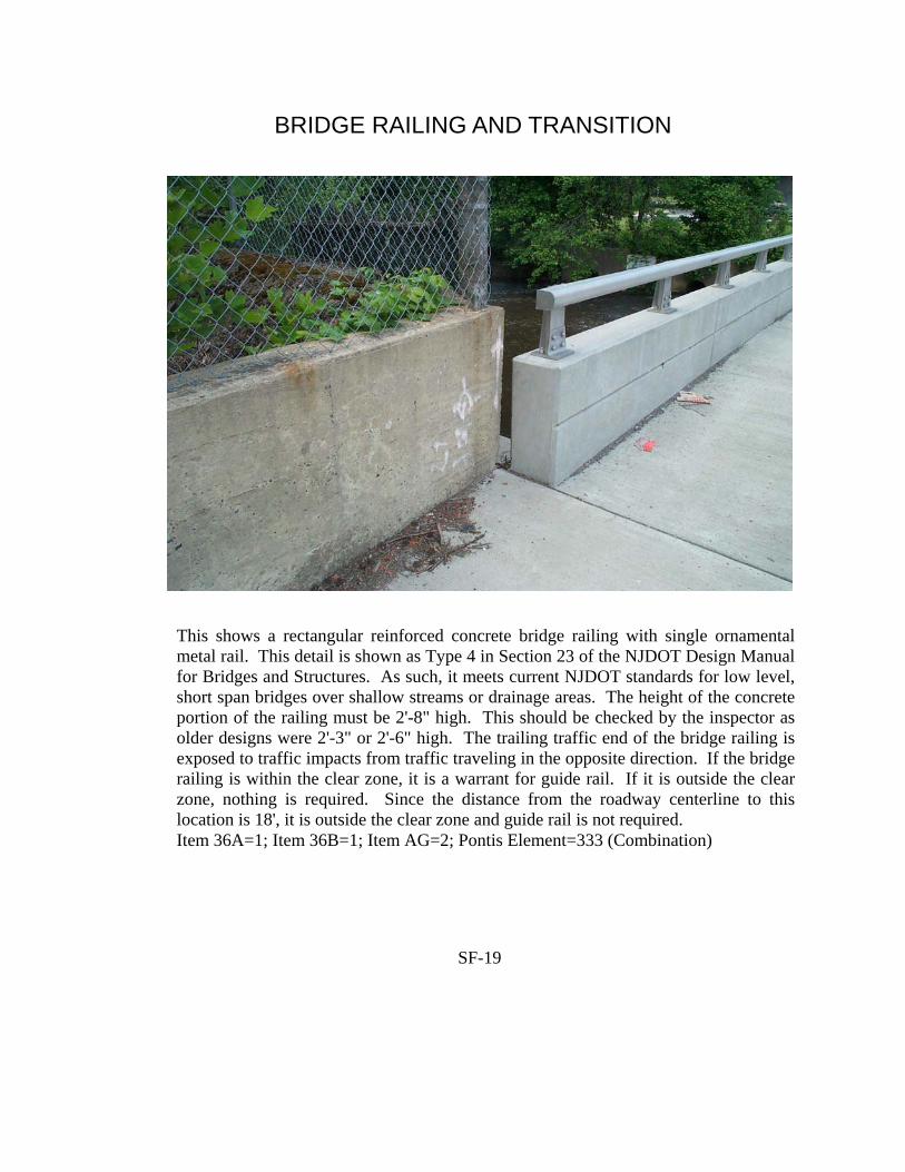
SF-19
BRIDGE RAILING AND TRANSITION
This shows a rectangular reinforced concrete bridge railing with single ornamental metal rail. This detail is shown as Type 4 in Section 23 of the NJDOT Design Manual for Bridges and Structures. As such, it meets current NJDOT standards for low level, short span bridges over shallow streams or drainage areas. The height of the concrete portion of the railing must be 2'-8" high. This should be checked by the inspector as older designs were 2'-3" or 2'-6" high. The trailing traffic end of the bridge railing is exposed to traffic impacts from traffic traveling in the opposite direction. If the bridge railing is within the clear zone, it is a warrant for guide rail. If it is outside the clear zone, nothing is required. Since the distance from the roadway centerline to this location is 18', it is outside the clear zone and guide rail is not required. Item 36A=1; Item 36B=1; Item AG=2; Pontis Element=333 (Combination)

SF-20
BRIDGE RAILING AND TRANSITION
Typical detail for a D&R Canal bridge with retrofitted bridge railing and guide rail transition. The bridge railing is a unique design for D&R Canal bridges and has not been crash tested. However, due to the low traffic volume and speeds on the D&R Canal bridges, this bridge railing is deemed to meet current NJDOT standards. The guide rail attachment detail is likewise unique, but is also deemed to meet NJDOT standards. The inspector should check that the transition has double element guide rail and post spacing that meets the current standards. Item 36A=1; Item 36B=1; Item AG=18; Pontis Element=334 (Metal—Coated)

SF-21
BRIDGE RAILING AND TRANSITION
This shows a concrete encased through girder type bridge railing retrofitted with a steel w-beam guide rail mounted on top. This detail is somewhat unusual and is not shown in the NJDOT Roadway Construction Details. Obviously, this detail was not crash tested. However, it would appear to meet design criteria based on inspection (excepting the lack of a double rail w-beam). The transition zone is clearly substandard due to the lack of adequate post spacing and lack of double rail w-beam. Item 36A=0; Item 36B=0; Item AG=18; Pontis Element=333 (Combination)

SF-22
BRIDGE RAILING AND TRANSITION
This shows a double rail w-beam bridge railing with the approach guide rail carried into the transition zones at both approaches. This detail is somewhat unique and is not shown in the NJDOT Roadway Construction Details. The bridge railing lacks spacer blocks on the posts. In addition, the posts appear to be mounted on the outside bridge fascia bringing the strength of the system into question. This type of system would not have been crash tested. The guide rail in the transition zone lacks adequate post spacing, spacer blocks and double rail w-beam. Finally, the ends of the curb are not tapered and are exposed to impacts. Item 36A=0; Item 36B=0; Item AG=18; Pontis Element=334 (Metal-Coated)

This is the NJDOT’s standard thrie beam guide rail transition to a concrete bridge railing at the leading traffic end. This detail is shown on Sheet 70 of the NJDOT Roadway Construction Details, CD-609-13. The inspector should verify that the spacing of the guide rail posts in the transition zone meets current NJDOT standards. Item 36B = 1 due to Structural tube blockouts.
SF-23
GUIDE RAIL TRANSITION

SF-24
BRIDGE RAILING, TRANSITION, GUIDE RAIL AND END TERMINAL
This shows a rectangular reinforced concrete bridge railing with a single ornamental metal rail. This detail is shown as Type 4 in Section 23 of the NJDOT Design Manual for Bridges and Structures. As such, it meets NJDOT standards for low level, short span bridges over shallow streams or drainage areas. The inspector should check the height of the bridge railing to verify that it is 2'-8". The leading traffic end of the bridge railing is exposed to vehicle impacts. The inspector should check to verify if this location is within the clear zone. If so, the design would be substandard. In this particular case, the end of the bridge railing is 18' from the edge of the traffic lane which is outside the clear zone. Item 36A=1; Item 36B=1; Item 36C=1; Item 36D=1; Item AG=02; Pontis Element=333 (Combination)

SF-25
BRIDGE RAILING, TRANSITION, GUIDE RAIL AND END TERMINAL
This shows an older two pipe metal bridge railing with steel w-beam approach guide rail. Just about everything is substandard. The bridge railing would fail both in strength and geometry. The approach guide rail transition lacks adequate post spacing, spacer blocks, double rail w-beam and attachment to the bridge railing. The approach guide rail lacks spacer blocks, adequate post spacing and adequate length. Finally, there is no end terminal. Item 36A=0; Item 36B=0; Item 36C=0; Item 36D=0, Item AG=18; Pontis Element=334 (Metal-Coated)

SF-26
TRANSITION
This is the NJDOT’s standard approach guide rail transition to a NJ barrier type bridge railing at the leading traffic end. The inspector should verify that the spacing of the guide rail posts in the transition zone meets current NJDOT standards. Item 36B= 0 due to lack of Structural tube blockouts.
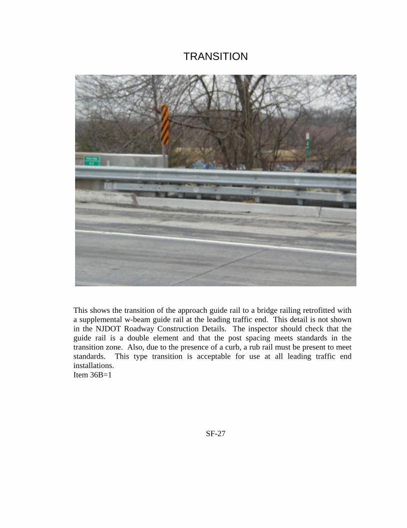
SF-27
TRANSITION
This shows the transition of the approach guide rail to a bridge railing retrofitted with a supplemental w-beam guide rail at the leading traffic end. This detail is not shown in the NJDOT Roadway Construction Details. The inspector should check that the guide rail is a double element and that the post spacing meets standards in the transition zone. Also, due to the presence of a curb, a rub rail must be present to meet standards. This type transition is acceptable for use at all leading traffic end installations. Item 36B=1

SF-28
TRANSITION
This shows the transition of the approach guide rail to a NJ Barrier type bridge railing at the leading traffic end. The attachment to the bridge railing, rub rail, spacer blocks and pipe spacer meet standards, the post spacing in the transition and single element w-beam do not. Item 36B=0

SF-29
TRANSITION
This shows a steel w-beam transition to the concrete end pylon of a bridge railing. The pictured transition does not meet NJDOT standards because it is not properly attached to the end pylon and it lacks adequate post spacing and double rail w-beam in the transition zone. Item 36B=0

SF-30
TRANSITION
This shows a substandard transition to a reinforced concrete balustrade type bridge railing where the guide rail has been installed as a supplement to the original bridge railing. This installation is substandard because there is no double-element w-beam in the transition zone. Also, the post spacing in the transition zone is substandard. Finally, the pipe spacer at the end pylon of the balustrade is lacking. The standard detail for this installation is shown on Sheet 67 of the NJDOT Roadway Construction Details, CD-609-10.1. Item 36B=0

SF-31
TRANSITION
This shows the guide rail transition zones at the end of a bridge carrying two way traffic without a median barrier. The transition at the right is a typical design for the leading traffic end of a bridge railing. The transition on the left is a different matter since the inspector must determine whether the guide rail “warrant” (end of bridge railing) is within the “clear zone” for traffic traveling in the right hand lane. Since the curb-to-curb width is 30' and the sidewalk width is 6', the end of the bridge railing is 21' from the centerline of the roadway. This means that the end of the bridge railing is outside the “clear zone” for speeds of up to 50mph. If the speed limit on this road is less than or equal to 50mph, the end of the bridge railing requires a transition for the trailing traffic end condition rather than the leading traffic end condition. For posted speeds of over 50mph, the end of the bridge railing is a “warrant” within the “clear zone” and requires a transition for the leading traffic end condition similar to what is on the right.

SF-32
TRANSITION, GUIDE RAIL AND END TERMINAL
This shows the trailing traffic end of a bridge railing in the median of an interstate highway. The end of the bridge railing is not exposed to impacts by traffic carried by the bridge. It is also outside the “clear zone” for traffic carried by the twin bridge. Therefore, there is no “warrant” for guide rail at this location. Item 36B=1; Item 36C=1; Item 36D=1

SF-33
END TERMINAL
This is the NJDOT’s standard Slotted Rail Terminal (SRT-350). This end terminal is acceptable and meets current NJDOT standards for all installations. It is typically used where room to flare the guide rail exists. Where inadequate space exists to flare, the Extruder Terminal (ET-2000) would be used for most installations. Item 36D=1

SF-34
END TERMINAL
This is the NJDOT’s standard Extruder Terminal (ET-2000). This detail is shown on Sheet of the NJDOT Roadway Construction Details, CD-609-5.2. This end terminal is acceptable and meets current NJDOT standards for all installations. It is typically used where room to flare the guide rail does not exist. Where adequate room exists to flare, the Slotted Rail Terminal (SRT-350) would be used for most installations. Item 36D=1

SF-35
END TERMINAL
This shows the end of the guide rail buried at the leading traffic end in a cut slope. This type of detail requires an in line anchorage to meet NJDOT standards as shown on Sheet 65 of the NJDOT Roadway Construction Details, CD-609-8.4. This type of end terminal would be preferable and acceptable for all leading traffic end installations if the in line anchorage was present. In-line anchorage may be eliminated by constructing at least 7 posts at 6’-3” spacing beyond length of need (L.O.N.). The inspector should verify that the spacing of the posts meets current NJDOT standards. Item 36D = 1 (if meets standards) otherwise Item 36D = 0.
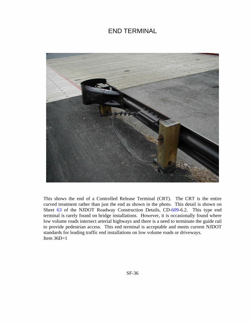
SF-36
END TERMINAL
This shows the end of a Controlled Release Terminal (CRT). The CRT is the entire curved treatment rather than just the end as shown in the photo. This detail is shown on Sheet 63 of the NJDOT Roadway Construction Details, CD-609-6.2. This type end terminal is rarely found on bridge installations. However, it is occasionally found where low volume roads intersect arterial highways and there is a need to terminate the guide rail to provide pedestrian access. This end terminal is acceptable and meets current NJDOT standards for leading traffic end installations on low volume roads or driveways. Item 36D=1

SF-37
END TERMINAL
This shows the trailing traffic end guide rail end anchorage. This detail is shown on Sheet 61 of the NJDOT Roadway Construction Details, CD-609-4. This end terminal is acceptable and meets current NJDOT standards for all trailing traffic end installations. Item 36D=1

SF-38
END TERMINAL
This shows a Breakaway Cable Terminal (BCT) with collision damage at the leading traffic end. The BCT saw widespread use throughout New Jersey. However, it failed crash testing, no longer meets NJDOT standards and is not shown in the NJDOT Roadway Construction Details. It is always evaluated as substandard on NJDOT infrastructure. It may be acceptable for bridge owners in New Jersey for highways not on the NHS. Item 36D=0 NOTE: The presence of the collision damage would not affect the evaluation of the safety features. In fact, the end terminal could be completely destroyed by impact damage and the design could still meet standards.

SF-39
END TERMINAL
This shows an Eccentric Loader Terminal (ELT). This type end terminal no longer meets NJDOT standards. It is always evaluated as substandard on NJDOT infrastructure. Item 36D=0

SF-40
END TERMINAL
This shows a guide rail that has been flared and buried at the end terminal in a fill slope. This detail does not meet current NJDOT standards. The end of a guide rail can be buried at the end in cut slopes only. This installation is substandard for all situations. Item 36D=0

SF-41
END TERMINAL
This shows a typical telescoping guide rail end terminal of the telescoping type. This detail is shown on Sheet 64 of the NJDOT Roadway Construction Details, CD-609-7.3. This type end terminal is rarely used on bridges. However, it is commonly used on highway underpass structures when a pier is located in the median. However, the adequacy of such installations is not evaluated when determining the coding for Item 36.

SF-42
END TERMINAL
This shows a Median Breakaway Cable Terminal (MBCT). The replacement for this type end terminal is either the CAT or BREAKMASTER. This type end terminal is rarely used on bridges. However, it is commonly used on highway underpass structures when a pier is located in the median as shown above. However, the adequacy of such installations is not evaluated when determining the coding for Item 36.

APPENDIX G ITEMS GD-GO - PAINT CONDITION RATINGS - WEATHERING STEEL

Paint Condition Ratings - Weathering Steel (SI&A Items GD-GO) What To Rate Rate the effectiveness of the iron oxide coating (patina) on the steel superstructure. The effectiveness should be determined based on the color and texture of the surface of the steel. Theory Of Weathering Steel Weathering steel refers to a carbon base steel that is alloyed with approximately 2% copper, nickel, chromium and silicon. These additions are intended to inhibit the steel’s natural tendency to continuously rust in the outside environment. When used in a suitable environment, this steel eliminates the need for painting because steel “weathers” to form a patina, or thin layer of protective oxide coating, that prevents or minimizes further rusting. The patina will not form properly if the steel remains wet for extended periods of time or is contaminated with salt or other chemicals, especially if the bridge is exposed to these conditions soon after construction. Patina formation time will vary according to any factors and may take 2-3 years or more to form completely. If the patina has not properly formed, the steel will continue to corrode. This will appear as either continuous flaking of the plates and/or by plate delamination. The plate delamination will appear as open cracks along the vertical edges of the flange plates or by blistering (bulging) on flat surface areas. What To Look For Inspect the formation of the patina by observing it’s color and texture. The color of a properly formed patina will vary with the age of the steel and it’s chemical composition. Generally, the color will change over time from light yellow orange to dark chocolate or purple. An improperly formed patina will generally appear dark black. A properly formed patina has tight mill scale or a tight granular consistency which will not be adversely effected by vigorous brushing with a wire brush. An improperly formed patina will generally have flakes and/or delaminations which can be removed with a hammer tap, a wire brush or chipping hammer. Section loss in the base metal of the steel girders should principally be indicated in the Pontis ratings for the superstructure or substructure members. Paint Condition Ratings - Scale For Weathering Steel The rating will be based on the percentage of the protective oxide layer or patina that has failed. This is based on the percentage of the member being rated that exhibits a dark black patina or where flakes and/or delaminations can be removed as stated above.
SG-1
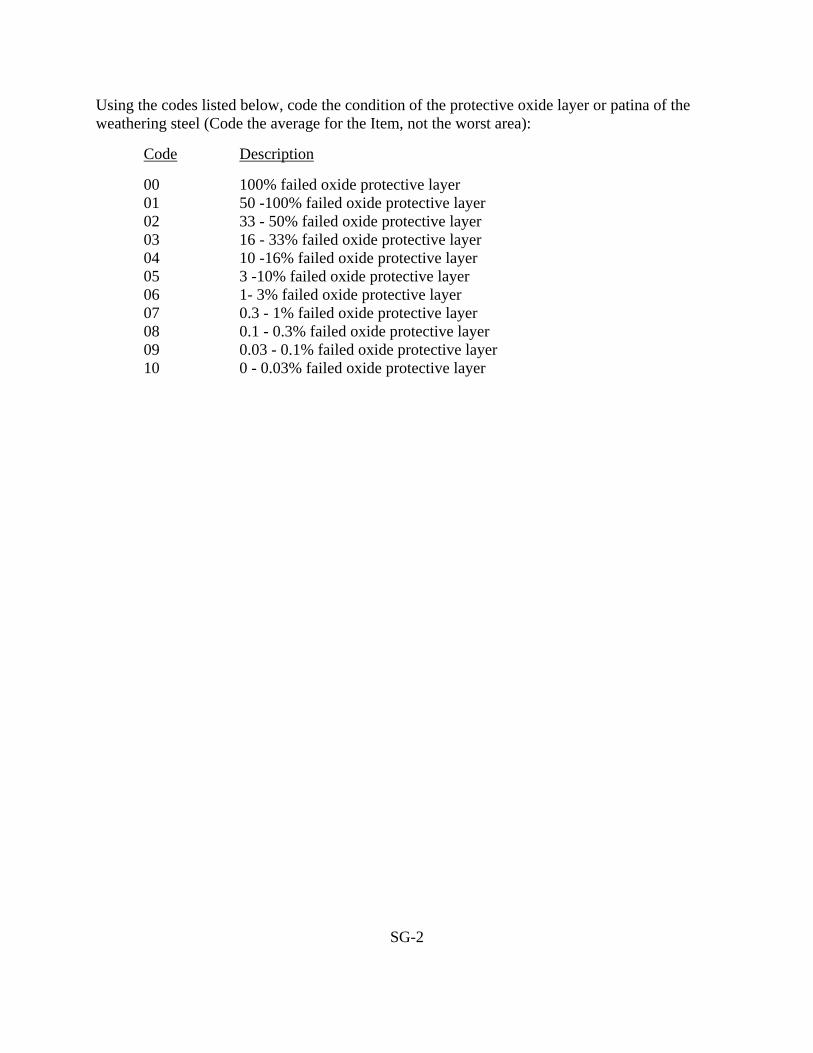
Using the codes listed below, code the condition of the protective oxide layer or patina of the weathering steel (Code the average for the Item, not the worst area): Code Description
00 100% failed oxide protective layer 01 50 -100% failed oxide protective layer 02 33 - 50% failed oxide protective layer 03 16 - 33% failed oxide protective layer 04 10 -16% failed oxide protective layer 05 3 -10% failed oxide protective layer 06 1- 3% failed oxide protective layer 07 0.3 - 1% failed oxide protective layer 08 0.1 - 0.3% failed oxide protective layer 09 0.03 - 0.1% failed oxide protective layer 10 0 - 0.03% failed oxide protective layer
SG-2

APPENDIX A
RAILROAD BRIDGE CODOING INSTRUCTIONS

RAILROAD CARRYING BRIDGES
CODING INSTRUCTIONS
R-1

RAILROAD CARRYING BRIDGES
This guide has been prepared for use in recording and coding the data elements on record one (Item 5A=1) that will form a railroad carrying bridge inventory database. The data requested includes both Federal and State fields as they apply to railroad carrying structures. The required data is to be coded and submitted according to the definitions and classifications contained in both the Federal and State Coding Guides with all exceptions contained herein. For first cycle inspections (without previous SI&A sheets), the input screens contained herein should be filled-in using a pen or hard pencil so that the data can be input into the database. For re-inspections, any changes should be marked-up on the SI&A input screens in a similar manner. Existing data for re-inspections that is correctly coded should be left without change on the SI&A. In both cases, a print-out of the final SI&A sheet(s) will be developed from the database for placement in the bridge survey report. For general coding instructions, see page 3 of the State Coding Guide. If a second record (or A-Z) is needed for the highway below, then the items specified on page 2 of the Federal Coding Guide shall also be coded . In addition, State Items A, AA, AB and DJ shall be coded in accordance with the State Coding Guide. Note: Throughout this Coding Guide, the term “Conrail” is meant to refer to railroads owned
by CSX and Norfolk Southern including the “Joint Assets”.
R-1

EXCEPTIONS TO FEDERAL ITEMS The following items should be left Blank on record 5A=1: 11, 19, 20, 28, 29, 30, 32, 33, 51, 70, 72, 95, 100, 101, 102, 108, 109, 110, 114 and 115. ITEM 5B - ROUTE SIGNING PREFIX 1 DIGIT The second position of Item 5 shall be coded 8. ITEM 5D - ROUTE NUMBER 5 DIGITS Code the railroad route number in the next 5 positions, which shall be right justified with leading zeros. See Appendix I for railroad route listings. ITEM 21 - MAINTENANCE RESPONSIBILITY 2 DIGITS Code Description 01 State owned Railroad Bridges (not including NJT) 21 NJ Transit owned Bridges 27 All other Railroad Bridges ITEM 22 - OWNER 2 DIGITS Same as Item 21. ITEM 26 - FUNCTIONAL CLASSIFICATION 2 DIGITS Code Description 96 Abandoned Railroad Lines 97 Passenger & Freight 98 Freight Only 99 Passenger Only ITEM 36 - SAFETY FEATURES 4 DIGITS The codes 0, 1 and N shall be used for coding this item. However, the following shall apply: Digit Position Guide Rail 1st Location 2nd Attachment 3rd Extension 4th Ends of guard rail
R-2

ITEM 36 - SAFETY FEATURES 4 DIGITS Digit Position Guide Rail 1. Location: The guard rails are located on the structure and are 10” (+) from
the running rails. 2. Attachment: The guard rails are firmly attached to the structure. 3. Extension: The guard rails extend at least 50’ beyond both ends of the
structure. 4. Ends of guard rail: The ends of the guard rails are bevelled down and meet at the
center of the track. * Guard rails are steel rails inside the actual running rails which are used to keep the train
from striking the structure, should the train derail. ITEM 41 - STRUCTURE OPEN, POSTED OR CLOSED 1 DIGIT Code Description A Open K Closed R Speed Restriction ITEM 47 - INVENTORY ROUTE, TOTAL HORIZONTAL 3 DIGITS CLEARANCE The minimum horizontal clearance should be coded in this item with two stipulations: 1. Measure horizontal clearance (+/-) 4’ above the top of the rails from the center line of the
track to the nearest obstruction on each side. 2. Measure horizontal clearance at the top of rail from the centerline of the track to the
nearest obstruction at each side (see attachment). If the horizontal clearance measurement at +/- 4’ as mentioned above is not possible then the measurement shall be take 2’ above the top of rail. Both of these clearances should be measured and the one that does not meet the minimum should be noted. If both stipulations meet the minimum horizontal clearance, the most restrictive measurement should be noted.
If the bridges as no horizontal clearance restrictions (i.e., deck girder, timber trestle, etc.), Code
99.9.
R-3

Attachment for Item 47
TRACK ON TANGENT Minimum Horizontal Clearance
R-4

ITEM - 58 DECK 1 DIGIT Same as Federal Coding Guide The following type of structure should receive special attention. Open Deck (Railroad Bridges) For railroad bridges which have open decks, the deck condition shall be coded based on the condition of the railroad ties, in accordance with the condition ratings shown in the current Federal Coding Guide. ITEM 64 - OPERATING RATING 3 DIGITS The second and third digits will give the equivalent Cooper E loading (based on allowable operating stresses) if known, otherwise code “700”. ITEM 66 - INVENTORY RATING 3 DIGITS The second and third digits will give the equivalent Cooper E loading (based on allowable inventory stresses) if known, otherwise code “700”. ITEM 67 - STRUCTURAL EVALUATION 1 DIGIT The structural condition should be evaluated based on the following criteria: I. For N.J.D.O.T. owned Railroad Carrying Structures Code Remark 9 Inventory rating greater than Cooper E80 loading, with full impact 8 Inventory rating equal to Cooper E80 loading, with full impact 7 Inventory rating greater than Conrail loading, with full impact 6 Inventory rating greater than or equal to Conrail loading with a speed
restriction chart 5 Operating rating greater than Conrail loads, with full impact 4 93% of operating rating with impact computed at 10 mph is greater than or
equal to Conrail loading 3 93% of operating rating with impact computed at 10 mph is less than
Conrail loading 0 Closed NOTE: The Conrail Equivalent Cooper E loadings can be found in the special loading
charts which are part of the current N.J.D.O.T. Design Manual - Bridges and Structures.
R-5

ITEM 67 - STRUCTURAL EVALUATION 1 DIGIT II. NJ Transit/Conrail owned Railroad Carrying Structures Code Remarks 9 Inventory rating greater than Cooper E80 loading 8 Inventory rating equal to Cooper E80 loading 7 Bridge can carry all 6 Conrail loads. 6 Bridge can carry Conrail loads 1 thru 5 5 Bridge can carry Conrail loads 1 thru 4 4 Bridge can carry Conrail loads 1 thru 3 3 Bridge can carry Conrail loads 1 and 2 2 Bridge cannot carry any Conrail loads ITEM 68 - DECK GEOMETRY 1 DIGIT The appraisal of the minimum horizontal clearance from centerline of the track on the structure should be coded in this item. The following appraisal coding criteria should be used for tangent track: Rating
+4 Above Rail +2 Above Rail At Top of Rail
8 9’-0” 7’-6” 6’-0” 7 8’-6” 7’-2” 5’-9” 6 8’-0” 6’-9” 5’-6” 5 6’-9” 6’-1” 5’-4” 4 5’-7” 5’-4” 5’-1” 3 Below 5’-7” Below 5’-4” Below 5’-1” The most restrictive measurement should be used. AREA and Conrail recognize that by coding “4” this condition meets the minimum tolerable limits to be left in place. NOTE: If the track is curved on the structure the minimum horizontal clearance will
increase by 1 ½” for every degree of curve. For additional information, please refer to the American Railway Engineering
Association Manual for Railway Engineering, Volume 2, Chapter 28, Sections 1.1 and 1.2b and Chapter 15, Section 1.2.6. Also, refer to New Jersey Transit Plate 70051-B and MW 4 Section 213.57 to 213.61.
R-6

ITEM 68 - DECK GEOMETRY (CONTINUED) 1 DIGIT Examples: A. Thru-girder railroad bridge. Measurement taken from centerline of tangent track: +/- 4’ above rail = 8’-7” +/- 2’ above rail = 6’10” Top of Rail = 5’-9” Since the most crucial measurement is at +/- 2’ above rail, the rating would be “6”. B. Same as Example A, except track on structure has a 2 degree curve. The values in the
table on page 9 would be increased by 3” (2 degrees x 1 ½”). Therefore the most crucial of the above measurement is still +/- 2’ above the rail. The
new rating based on revising the table for a 2 degree curve is now a “5”. ITEM 69 - UNDERCLEARANCE, VERTICAL 1 DIGIT AND HORIZONTAL Refer to the Federal Coding Guide Section pages F56, F57 and F58 for coding this item. ITEM 104 - HIGHWAY SYSTEM OF THE INVENTORY ROUTE 1 DIGIT All railroad carrying structures will have a code of 9 if Item 5A = 1. ITEM 112 - NBIS BRIDGE LENGTH 1 DIGIT If structure length (as defined on page F78) is 5’-0” or greater, then code “Y”. If not, code “N”.
R-7
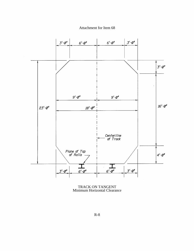
Attachment for Item 68
TRACK ON TANGENT Minimum Horizontal Clearance
R-8

EXCEPTIONS TO STATE ITEMS
ITEM BA - APPROACH ROADWAY CONDITION 1 DIGIT This Item reflects the physical condition of the tracks and the track bed in the approaches to the bridge. This Item should be coded based on erosion of embankment, condition of ties, loose tie plates and pumping of rails. Use the following table as an aid in coding this item. 8 Very Good Condition No Defects 7 Good Condition Light erosion of embankment, longitudinal
splitting and/or wide checking in ties
6
Satisfactory Condition Moderate erosion of embankment, light rotting in a few ties, moderate to heavy rotting in a few ties and/or some loose tie plates.
5 Fair Condition Heavy erosion of embankment, a few missing ties, moderate to heavy rotting in a few ties and/or a few loose tie plates.
4 Poor Condition Severe erosion of embankment causing undermining of ties, severe rotting in most items and/or many loose tie plates causing slight pumping of rails.
3 Serious Condition Same as 4 but with severe pumping of rails. ITEM A - TOWN 4 DIGITS Code the town where the bridge is located, see page S1. ITEM AA - ROUTE 5 DIGITS Code the railroad route number in the first four positions left justified with the fifth position left blank. See Railroad Bridge Coding Instructions Appendix A for railroad route listings.
R-9

ITEM AI - SPEED POSTING 2 DIGITS Code the posted speed limit for the bridge in miles per hour based on a speed restriction chart. Leave blank if not speed restriction posted. ITEM BC - USRA LINE CODE 4 DIGITS Leave blank. This item will be coded by the Structural Evaluation - “Railroad Section” . ITEM BE - RAILROAD MILEPOST 5 DIGITS For record 5A equals 1: For a railroad carrying bridge, code railroad milepost of the railroad line designated in Item 7 (Facility Carried by Structure). For record 5A equals 2 or A thru Z: If the feature intersected is a railroad line, code this item according to the railroad milepost of the railroad line as designated in Item 6 (Features Intersected). ITEM BK - PERCENT OVERSTRESS 2 DIGITS Leave blank ITEM BQ - LOAD 1 EQUIVALENT COOPER E 2 DIGITS For ratings in terms of Load 1, code the controlling member’s equivalent Cooper E load in the space provided. Should the equivalent loading be more than Cooper E99, code 99 in the space provided. ITEM BR - LOAD 2 EQUIVALENT COOPER E 2 DIGITS For ratings in terms of Load 2, code the controlling member’s equivalent Cooper E load in the space provided. Should the equivalent loading be for more than Cooper E99, code 99 in the space provided. ITEM BS - LOAD 3 EQUIVALENT COOPER E 2 DIGITS For ratings in terms of Load 3, code the controlling member’s equivalent Cooper E load in the space provided. Should the equivalent loading be for more than Cooper E99, code 99 in the space provided.
R-10

ITEM BT - LOAD 4 EQUIVALENT COOPER E 2 DIGITS For ratings in terms of Load 4, code the controlling member’s equivalent Cooper E load in the space provided. Should the equivalent loading be for more than Cooper E99, code 99 in the space provided. ITEM BU - LOAD 5 EQUIVALENT COOPER E 2 DIGITS For ratings in terms of Load 5, code the controlling member’s equivalent Cooper E load in the space provided. Should the equivalent loading be for more than Cooper E99, code 99 in the space provided. ITEM BV - LOAD 6 EQUIVALENT COOPER E 2 DIGITS For ratings in terms of Load 6, code the controlling member’s equivalent Cooper E load in the space provided. Should the equivalent loading be for more than Cooper E99, code 99 in the space provided. ITEM CG - POSTED LOAD 3 DIGITS Leave blank ITEM CP - FEDERAL REPORT 1 DIGIT For railroad carrying bridges over highways code “X” on Sheet “1” and leave blank on Sheet “2” or “A” through “Z”. Code “R” for the following categories: 1. Bridges carrying railroad traffic over waterways. 2. Bridges carrying railroad traffic over any other features (except highways). 3. Pedestrian bridges over or under a railroad.
R-11

APPENDIX A
RAILROAD BRIDGE CODING INSTRUCTIONS

1. New Jersey Transit Railroad Line Listing
RR Routes Rail System Name
4001 Pascack Valley Line 4002 Bergen County Line 4003 Main Line 4004 Boonton Line (MP 2.70 to 34.10) 4005 Morristown Line (MP 34.10 to 47.90) Morristown Line (MP 00.00 to 36.30) 4006 Harrison Connection 4007 Montclair Branch 4008 Gladstone Line 4009 Raritan Valley Line and Bayonne Branch 4011 North Jersey Coast Line 4012 Freehold Branch 4013 Freehold Secondary 4014 Southern Branch 4015 Princeton Line 4050 Atlantic City Line 4051 Cape May Line 4052 Ocean City Branch 4056 Millville Branch 4057 Pemberton Secondary
Example: (Item AA) Route 4001 - Code 4001b (Item BC) USRA Line Code 6152 - Code 6152 2. A “5000 to 5699” series is used to designate State owned railroad carrying bridges over
State owned routes. Example: Lehigh Valley Railroad over Rt. 1+9 Code Item AA as 51+9b 3. A “5700 to 5999” series is used to designate State owned railroad carrying bridges over
other features. 4. A “6000 to 6149” series is used to designate the Amtrak and Conrail Bridges. 6000b to 6099b - Amtrak-Northeast Corridor 6100b to 6149b - Conrail (Joint Assets), Norfolk Southern and CSX
RA-1

5. A “6150 to 6157” series is used to designate private railroads as follows:
Route Railroad Line 6150 All NY Susquehanna and Western Railroad Lines (owned by
Delaware & Otsego Railroad)—NYS&W RR
6151 Staten Island Rapid Transit (SIRT) 6152 Septa owned portion of the NY Branch (Former Reading
Railroad-USRA Line code 0326)
6153 Black River and Western Railroad (BR&W RR) 6154 Rahway Valley Railroad 6155 Morristown and Erie Railroad 6156 Miscellaneous abandoned Traction Companies (P.S. Trolley,
Bergen County Traction Company, etc.)
6157 Abandoned New York Branch Spur (to Pennington Mountain Quarry)
6. A “6158 to 6199” number series is used to designate miscellaneous railroad lines.
RA-2


![Accounts & Inventory ERP System[ ver: 1.0.102] Coding Profile Pre Shipment Purchase Sales Sampling Inventory Expiry Pharma Accounts Marketing Utilities Server Distributors Current](https://static.fdocuments.in/doc/165x107/5f25f3176f58614e1128b6ac/accounts-inventory-erp-system-ver-10102-coding-profile-pre-shipment.jpg)