Reconfigurable Multi Band Notches Antenna for Cognitive ... · Reconfigurable Multi Band Notches...
4
Reconfigurable Multi Band Notches Antenna for Cognitive Radio Applications H. LALJ ¹´², H. GRIGUER ², M. DRISSI ¹ 1 European University of Bretagne (UEB), National Institute of Applied Sciences (INSA) of Rennes, IETR Laboratory, France, [email protected] 2 Moroccan School of engineering Science (EMSI-Rabat), Morocco, [email protected] Abstract In this paper, a reconfigurable multi band notches antenna, for cognitive radio applications, is proposed. The antenna can be operated as ultra wideband, and is reconfigurable in terms of the ability to select one or two notches band in the SRR resonant frequency. The Reconfigurable band notches are induced using a band stop filter based on split-ring resonators (SRRs), and are controlled using two couple of ideal switches mounted over the SRRs. For this sake, the design of band stop filter is proposed. A prototype of filter is fabricated and measured. The incorporation of a band stop filter, into a wideband antenna, is then looked into. The proposed antenna is designed and simulated using Ansoft HFSS. A prototype of the antenna is fabricated and measured. A good analogy between simulated and measured results is obtained. 1.Introduction Antennas have become a necessary and critical component of all personal electronic devices, microwave and satellite communication systems. In many of these systems, there is a requirement to perform a multitude of functions across several frequency bands and operating bandwidths, especially in the area of cognitive radio. According to the Federal Communications Commission (FCC), a cognitive radio is “a radio that can change its transmitter parameters based on interaction with the environment in which it operates” [1, 2]. Thus, in cognitive radio system, we need the capability to sense the spectrum (“sensing” antenna), and communicate (“reconfigurable communicating” antenna). For these reasons, several antenna configurations have been developed for cognitive radio applications. In [3], a combination of wideband and narrowband antennas into the same volume is presented. The wideband antenna is a CPW fed printed hour-glass shaped monopole. The narrowband antenna is a microstrip patch printed on the reverse side of the substrate, and connected to the wideband antenna via a shorting pin. The authors in [4] discuss some of the possible antenna requirements for cognitive radio applications and outline some design approaches. In [5], the split-ring resonators [6] are employed in the design of UWB antennas with fixed notched bands. The authors in [7] present a design with a single band notch that can occur in the SRR resonant frequency. In this paper, we propose an antenna for cognitive radio applications. It has two band notches that are independently controllable. That is, one, two, or none of these notches can appear in the frequency profile of the UWB antenna. The rest of the paper is organized as follows. In Section 2, we propose a design of a bandstop filter based on SRRs etched close to the microstrip line. In Section 3, we present the design of the proposed antenna, and we discuss the simulated and measured obtained results, and finally the paper is concluded in Section 4. . 2.Bandstop Filter Design A microstrip transmission line is associated with a split ring resonator (SRR). The incident magnetic field needs to be polarized in the axial direction of the resonator, in this way; the resonator must be etched as close as possible to the line to increase the magnetic coupling. Accordingly, a band-stop phenomenon will appear in the vicinity of the SRR resonant frequency. The SRR unit cell was designed to operate around 6.2 GHz. The geometry of the cell is as follows: c =d = 0.3 mm, g = 0.6 mm and the global size is 4.6 mm *4.6 mm (Figure1. (a)). The substrate used is a RT/Duroid having the following characteristics (relative permittivity εr=2.2, loss tangent tg(φ)=0.0001 and thickness h=0.8 mm). The proposed filter as shown in Figure1.(b) is based on a 50 Ω line and a SRR unit cell etched close to the microstrip line designed in the microstrip technology. Figure1.(c) presents the band stop filter simulated results. It has a central frequency of 6.2 GHz and a rejection band as 600 MHz, a rejection band (S21= -10dB) is obtained in the designed frequency with low return loss. 978-1-4673-5225-3/14/$31.00 ©2014 IEEE
Transcript of Reconfigurable Multi Band Notches Antenna for Cognitive ... · Reconfigurable Multi Band Notches...
Reconfigurable Multi Band Notches Antenna for Cognitive Radio Applications
H. LALJ ¹´², H. GRIGUER ², M. DRISSI ¹
1 European University of Bretagne (UEB), National Institute of Applied Sciences (INSA) of Rennes, IETR Laboratory, France,
[email protected] 2 Moroccan School of engineering Science (EMSI-Rabat), Morocco, [email protected]
Abstract
In this paper, a reconfigurable multi band notches antenna, for cognitive radio applications, is proposed. The
antenna can be operated as ultra wideband, and is reconfigurable in terms of the ability to select one or two notches
band in the SRR resonant frequency. The Reconfigurable band notches are induced using a band stop filter based on
split-ring resonators (SRRs), and are controlled using two couple of ideal switches mounted over the SRRs. For this
sake, the design of band stop filter is proposed. A prototype of filter is fabricated and measured. The incorporation of a
band stop filter, into a wideband antenna, is then looked into. The proposed antenna is designed and simulated using
Ansoft HFSS. A prototype of the antenna is fabricated and measured. A good analogy between simulated and measured
results is obtained.
1. Introduction Antennas have become a necessary and critical component of all personal electronic devices, microwave and
satellite communication systems. In many of these systems, there is a requirement to perform a multitude of functions
across several frequency bands and operating bandwidths, especially in the area of cognitive radio. According to the
Federal Communications Commission (FCC), a cognitive radio is “a radio that can change its transmitter parameters
based on interaction with the environment in which it operates” [1, 2]. Thus, in cognitive radio system, we need the
capability to sense the spectrum (“sensing” antenna), and communicate (“reconfigurable communicating” antenna). For
these reasons, several antenna configurations have been developed for cognitive radio applications. In [3], a
combination of wideband and narrowband antennas into the same volume is presented. The wideband antenna is a CPW
fed printed hour-glass shaped monopole. The narrowband antenna is a microstrip patch printed on the reverse side of
the substrate, and connected to the wideband antenna via a shorting pin. The authors in [4] discuss some of the possible
antenna requirements for cognitive radio applications and outline some design approaches. In [5], the split-ring
resonators [6] are employed in the design of UWB antennas with fixed notched bands. The authors in [7] present a
design with a single band notch that can occur in the SRR resonant frequency.
In this paper, we propose an antenna for cognitive radio applications. It has two band notches that are
independently controllable. That is, one, two, or none of these notches can appear in the frequency profile of the UWB
antenna. The rest of the paper is organized as follows. In Section 2, we propose a design of a bandstop filter based on
SRRs etched close to the microstrip line. In Section 3, we present the design of the proposed antenna, and we discuss
the simulated and measured obtained results, and finally the paper is concluded in Section 4.
.
2. Bandstop Filter Design
A microstrip transmission line is associated with a split ring resonator (SRR). The incident magnetic field needs to
be polarized in the axial direction of the resonator, in this way; the resonator must be etched as close as possible to the
line to increase the magnetic coupling. Accordingly, a band-stop phenomenon will appear in the vicinity of the SRR
resonant frequency.
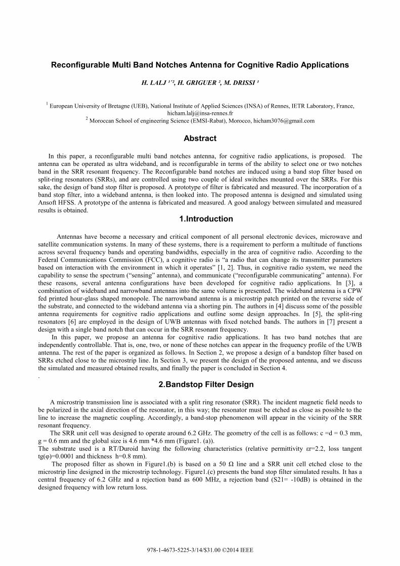
The SRR unit cell was designed to operate around 6.2 GHz. The geometry of the cell is as follows: c =d = 0.3 mm,
g = 0.6 mm and the global size is 4.6 mm *4.6 mm (Figure1. (a)).
The substrate used is a RT/Duroid having the following characteristics (relative permittivity εr=2.2, loss tangent
tg(φ)=0.0001 and thickness h=0.8 mm).
The proposed filter as shown in Figure1.(b) is based on a 50 Ω line and a SRR unit cell etched close to the
microstrip line designed in the microstrip technology. Figure1.(c) presents the band stop filter simulated results. It has a
central frequency of 6.2 GHz and a rejection band as 600 MHz, a rejection band (S21= -10dB) is obtained in the
designed frequency with low return loss.
978-1-4673-5225-3/14/$31.00 ©2014 IEEE
(a) (b) (c)
Figure 1: (a) SRR unit cell (b) Design of bandstop filter based on SRR (c) Simulated S parameters results
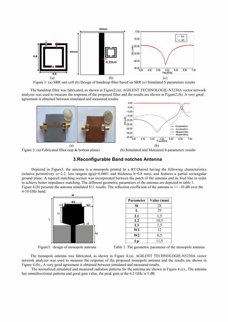
The bandstop filter was fabricated, as shown in Figure2.(a). AGILENT TECHNOLOGIE-N5230A vector network
analyzer was used to measure the response of the proposed filter and the results are shown in Figure2.(b). A very good
agreement is obtained between simulated and measured results.
(a) (b)
Figure 2: (a) Fabricated filter (top & bottom plane) (b) Simulated and Measured S parameters results
3. Reconfigurable Band notches Antenna
Depicted in Figure3, the antenna is a monopole printed In a RT/Duroid having the following characteristics
(relative permittivity εr=2.2, loss tangent tg(φ)=0.0001 and thickness h=0.8 mm), and features a partial rectangular
ground plane. A tapered matching section was incorporated between the patch of the antenna and its feed line in order
to achieve better impedance matching. The different geometric parameters of the antenna are depicted in table 1.
Figure 4.(b) presents the antenna simulated S11 results. The reflection coefficient of the antenna is << -10 dB over the
4-10 GHz band.
Figure3: design of monopole antenna Table 1: The geometric parameter of the monopole antenna
The monopole antenna was fabricated, as shown in Figure 4.(a). AGILENT TECHNOLOGIE-N5230A vector
network analyzer was used to measure the response of the proposed monopole antenna and the results are shown in
Figure 4.(b).. A very good agreement is obtained between simulated and measured results.
The normalized simulated and measured radiation patterns for the antenna are shown in Figure 4.(c).. The antenna
has omnidirectional patterns and good gain value, the peak gain at the 6.2 GHz is 5 dB.
Parameter Value (mm)
W 28
L 29
L1 1,5
L2 10,5
L3 1,5
W1 12
W2 6,5
Lp 11,5

(a) (b) (c)
Figure 4: (a) Photograph of the fabricated monopole antenna (b) Simulated and Measured S parameters for the
monopole antenna (c) Simulated & measured radiations pattern at 6.2 GHz for the monopole antenna in the E, and H
plane
To induce band notches, both the bandstop filter and the UWB antenna was assembled in a single structure, two
couple of identical rectangular split rings are placed close to the microstrip line feed. Their sizes are optimized so that
the larger rectangular split-ring causes a notch in the 6 GHz band, the smaller one in the 8 GHz band. To enable band
notch reconfigurability, two couple of electronic switches (S1, S1’) and (S2, S2’), are mounted across the split-ring
resonators, as shown in Figure 5.
Depending on the state of a switch, the corresponding split ring slot does or does not induce a band notch. When the
Switch is OFF, the single-ring complementary split-ring resonator (SRR) causing a notch in its design band. When the
couple (S1, S1’) is OFF, the large rectangular SRR causes a notch in the 6 GHz band, which disappears when it is ON.
For the smaller rectangular SRR, a notch appears when the (S2, S2’) is OFF, and disappears when it is ON. The
different switching cases are depicted in table 2.
Figure 5: design of reconfigurable multi Table 2: Switching cases and the corresponding notched bands
band notches antenna
The antenna was designed and simulated using Ansoft HFSS, the return loss was simulated for the different cases
states, which are listed in Table 2. A prototype was fabricated (Figure 6.(a)) , and the return loss was measured for the
four possible operation scenarios. Figure (6.(b)) show the computed and measured return loss plots for some of the
switching cases. Good analogy is shown between the simulated and measured results.
For Case 1, the two couple (S1, S1’) and (S1, S1’) are ON, in this case, none of the SRR resonates, and as a result,
no notch appears in the frequency response of the UWB antenna. For the Case 2, two notches are obtained in the 6 and
8 GHz bands when the two couple (S1, S1’) and (S2, S2’) is OFF.
The normalized simulated and measured radiation patterns for case 1, at 6 GHz, are shown in Figure 6.(c). The
omnidirectionality of the patterns is clear. For this switching case, the peak gain at 6 GHz is 5dB. For Cases 2 and 4,
where a notch occurs in the 6 GHz band, this gain drops to negative values due to strong reflections at the antenna’s
port.
Case
(S2, S2’)
(S1, S1’)
Notch
Bands (GHz)
1 ON ON None (ULB)
2 ON OFF 6
3 OFF ON 8
4 OFF OFF 6 ; 8

(a) (b)
(c)
Figure 6: Fabricated band notches antenna (top & bottom plane ) (b) : Simulated and Measured S parameters for the
band notches antenna (c) Simulated & measured radiations pattern at 6GHz for the case 1 in the E, and H plane.
4. Conclusion In this paper, a cognitive radio antenna was proposed. The design is based on a band stop filter, which is
integrated into a wideband monopole antenna. The antenna has a UWB response, and can have up a two independently
reconfigurable band notches that are induced by SRRs, and controlled by ideal switches mounted over the SRRs. The
antenna with different configuration of switches is fabricated and measured. The simulated and measured S parameter,
radiation patterns, and peak gains of the proposed Antenna are given and discussed. A credible analogy between
simulated and measured results is attained. The proposed antenna can be operated in UWB Cognitive Radio systems.
5. References
[1] J. Mitola and G. Q. Maguire, “Cognitive radio: making software radios more personal,” IEEE Pers. Commun.,
vol. 6, no. 4, pp. 13–18, Aug. 1999.
[2] FCC, “Report of the spectrum efficiency working group”, FCC spectrum policy task force, Tech. Rep., Nov. 2002.
[3] E. Ebrahimi, J. R. Kelly and P. S. Hall, “A reconfigurable narrowband antenna integrated with wideband monopole
for cognitive radio applications”, IEEE Antennas and Propagation Society International Symposium ( APSURSI),
2009.
[4] P. Gardner, M. R. Hamid, P. S. Hall, J. Kelly, F. Ghanem, and E.Ebrahimi, “Reconfigurable antennas for
cognitive radio: Requirements and potential design approaches,” in Proc. IET Seminar Wideband, Multi band
Antennas Arrays Defense Civil Appl.,Mar. 2008, pp. 89–94.
[5] Y. Zhang et al., “Planar ultrawideband antennas with multiple notched bands based on etched slots on the patch
and/or split ring resonators on the feed line,” IEEE Trans. Antennas Propagat., vol. 56, no. 9, pp. 3063–3068, Sept.
2008.
[6] J. B. Pendry, A.J. Holden, D.J. Robbins, and W.J. Ste wart, “Magnetism from conductors and enhanced nonlinear
phenomena,” IEEE Trans. Microw. Theory Tech., vol. 47, no. 11, pp. 2075–2084, 1999.
[7] M. Al-Husseini, J. Costantine, C.G. Christodoulou, S.E. Barbin, A. El-Hajj, and K.Y. Kabalan, “A reconfigurable
frequency-notched UWB antenna with split-ring resonators,” in The 2010 Asia-Pacific Microwave Conference
(APMC2010), Yokohama, Japan, 7–10 December 2010.