RECOMMENDED REVISIONS TO UNIT STRESSES IN MACHINERY …
22
Envirodyne Engineers, Inc. Envirodyne Engineers, Inc. Envirodyne Engineers, Inc. Envirodyne Engineers, Inc. Envirodyne Engineers, Inc. Envirodyne Engineers, Inc. Envirodyne Engineers, Inc. Envirodyne Engineers, Inc. Envirodyne Engineers, Inc. Envirodyne Engineers, Inc. Envirodyne Engineers, Inc. Envirodyne Engineers, Inc. Envirodyne Engineers, Inc. Envirodyne Engineers, Inc. Envirodyne Engineers, lnc. Envirodyne Engineers, Inc. Envirodyne Engineers, Inc. Envirodyne Engineers, Inc. Envirodyne Engineers, Inc. Envirodyne Engineers, Inc. Envirodyne Engineers, Inc. Envirodyne Engineers, Inc. Envirodyne Engineers, Inc. Envirodyne Engineers, Inc. Envirodyne Engineers, Inc. Envirodyne Engineers, Inc. Envirodyne Engineers, Inc. Envirodyne Engineers, Inc. Envirodyne Engineers, Inc. Envirodyne Engineers, inc. Envirodyne Engineers, Inc. Envirodyne ~ngineers, Inc. Envirodyne Engineers, Inc. Envirodyne Engineers, Inc. Envirodyne Engineers, Inc. Envirodyne Engineers, Inc. Envirodyne Engineers, Inc. Envirodyne Engineers, Inc. Envirodyne Engineers, Inc. Envirodyne Engineers, Inc. Envirodyne Engineers, Inc. RECOMMENDED REVISIONS TO UNIT STRESSES IN MACHINERY PARTS ARlEIZlCAN SOCIETY OF MECHANICAL ENGINEERS SECOND BIENNIAL MOVABLE BRIDGE SYMPOSIUM presented by Joseph J. Hosanna, Associate Envirodyne Engineers, hc. November 1987 ~nvirodyne ~ngineers, Inc. Envirodyne Engineers, Inc.
Transcript of RECOMMENDED REVISIONS TO UNIT STRESSES IN MACHINERY …
Envirodyne Engineers, Inc. Envirodyne Engineers, Inc. Envirodyne Engineers, Inc. Envirodyne Engineers, Inc. Envirodyne Engineers, Inc. Envirodyne Engineers, Inc. Envirodyne Engineers, Inc. Envirodyne Engineers, Inc. Envirodyne Engineers, Inc. Envirodyne Engineers, Inc. Envirodyne Engineers, Inc. Envirodyne Engineers, Inc. Envirodyne Engineers, Inc. Envirodyne Engineers, Inc. Envirodyne Engineers, lnc. Envirodyne Engineers, Inc. Envirodyne Engineers, Inc. Envirodyne Engineers, Inc. Envirodyne Engineers, Inc. Envirodyne Engineers, Inc. Envirodyne Engineers, Inc. Envirodyne Engineers, Inc. Envirodyne Engineers, Inc. Envirodyne Engineers, Inc. Envirodyne Engineers, Inc. Envirodyne Engineers, Inc. Envirodyne Engineers, Inc. Envirodyne Engineers, Inc. Envirodyne Engineers, Inc. Envirodyne Engineers, inc. Envirodyne Engineers, Inc. Envirodyne ~ngineers, Inc. Envirodyne Engineers, Inc. Envirodyne Engineers, Inc. Envirodyne Engineers, Inc. Envirodyne Engineers, Inc. Envirodyne Engineers, Inc. Envirodyne Engineers, Inc. Envirodyne Engineers, Inc. Envirodyne Engineers, Inc. Envirodyne Engineers, Inc.
RECOMMENDED REVISIONS TO UNIT
STRESSES IN MACHINERY PARTS
ARlEIZlCAN SOCIETY OF MECHANICAL ENGINEERS
SECOND BIENNIAL MOVABLE BRIDGE SYMPOSIUM
presented by Joseph J. Hosanna, Associate
Envirodyne Engineers, hc.
November 1987
~nvirodyne ~ngineers, Inc. Envirodyne Engineers, Inc.

I
1. INTRODUCTION
I am s u r e , if you have e u e r d e s i g n e d a mach ine ry p a r t f o r
a mouable b r i d g e , t h a t you haue r e a d " i t " , and you r e a d N ~ ~ I I more t h a n o n c e . And t h e n you r e a d " i t " a g a i n ,
because " i t " c o n t a i n s so much u s e f u l 1 i n f o r m a t i o n . The ! k i t " I am t a l k i n g a b o u t i s t h e l a s t p a r a g r a p h o f A r t i c l e
2 . 5 . 1 1 - U n i t S t r e s s e s i n M a c h i n e r y P a r t s o f AASHTO's
" S t a n d a r d S p e c i f i c a t i o n s f o r Movable Highway B r i d g e s . "
Even t h o u g h t h e p a r a g r a p h i s q u i t e l e n g t h y , I haue o f t e n
t h o u g h t t h a t i t s s u b j e c t m a t t e r dese rves much more space
i n t h e S p e c i f i c a t i o n s . T h i s pape r r e u i e w s t h e c o n t e n t o f
t h i s p a r a g r a p h and makes s p e c i f i c recommendat ions
c o n c e r n i n g changes and a d d i t i o n s t o i t .
2. WHAT DOES IT S f i s
The last paragraph of Article 2.5.11 states that the
allowable unit stresses included in the article provide an
appropriate factor of safety against:
o Static Failure
o Fatigue with and without Stress Reuersal
o Stress-Raisers which produce stress concentrations of
140 percent of the computed stresses.
The article then goes on to describe, in general terms,
the types of details couered by the 140 percent stress
concentration factor. They include increases of stress:
o At shoulders of the bearings for trunnions and
counterweight sheave shafts.
o Near the hub at gear arms.
o &t the faces of pinions for integral shafts and
pinions.
o At keyways.
Of all the stress raisers described only the keyways are
further defined as to size and location. It states that
keyways shall haue a width not more than 1/4 the shaft
diameter and a depth not more than 1 / 8 the shaft
diameter. For other machinery elements it alludes to
fillets of "reasonable radius". This area of the
specifications on stress raisers is the one I feel should be expanded.
Lastly, the paragraph states that if a shaft has no
keyways or other stress raisers the unit stresses in the
shaft may be increased by 2 0 percent.

I
3. BACKGROUND
3 . 1 Factor of Safety
What is the actual factor of safety prouided by the
ualues listed in Rrticle 2.5.11, based on the
information prouided in the last paragraph? Since
"an appropriate factor of ~afety'~ is provided against
failure by fatigue with a maximum stress
concentration factor of 1.4 as stated in the last
paragraph of hrticle 2.5.11 then the actual factor of
safety is:
Where: F = Rctual Factor of Safety S
S = Endurance Limit Stress e K = Stress Concentration Factor t S = Rllowable Unit Stress a
F . Kt, and Sa are self explanatory. However, S
S needs further explanation. By definition the e
endurance limit stress is the maximum ualue of the
completely reversed bending stress, which a plain
specimen can sustain for 1,000,000 or more load
cycles without failure. Or, in other words, if the
stress in a machinery part neuer exceeds a certain
ualue called the endurance limit the part will last
indefinitely.
The endurance limit is dependent on the condition of
the part's surface. For a part with machined
s u r f a c e s a t p o i n t s o f maximum s t r e s s , t h e endurance
l i m i t i s a p p r o x i m a t e l y 3 5 t o 40 p e r c e n t o f t h e
u l t i m a t e s t r e n g t h o f t h e m a t e r i a l .
Upon i n s p e c t i o n o f t h e a l l o w a b l e u n i t s t r e s s e s i n t h e
AASHTO S p e c i f i c a t i o n s i t can be r e a d i l y seen t h a t t h e
v a l u e s f o r b e n d i n g a r e e q u a l t o 20 p e r c e n t o f t h e
u l t i m a t e s t r e n g t h o f t h e m a t e r i a l (Su), o r
R e a r r a n g i n g e q u a t i o n (1) and s u b s t i t u t i n g t h e v a l u e s
f o r Se and K t , we have
E q u a t i n g e q u a t i o n s ( 2 ) and ( 3 1 , and s o l v i n g f o r F s ,
we f i n d
T h e r e f o r e , FS = 1 . 4
N o t much of a f a c t o r o f s a f e t y , f o r a p a r t u n d e r g o i n g
a l a r g e number o f c y c l e s u n d e r t h e maximum l o a d i n g .
An i n t e r e s t i n g p o i n t i s t h a t t h e s t r e s s c o n c e n t r a t i o n
f a c t o r K t i m e s t h e f a c t o r o f s a f e t y i s e q u a l t o t
2 . Thus, i f t h e s t r e s s c o n c e n t r a t i o n f a c t o r i s
greater than two the part will fail from fatigue at less than one million cycles of loading.
3 . 2 Stress Concentration Factors
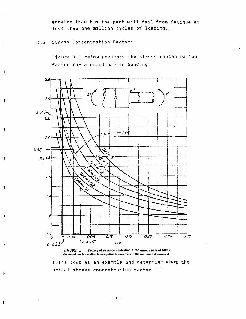
Figure 3 . 1 below presents the stress concentration
factor for a round bar in bending.
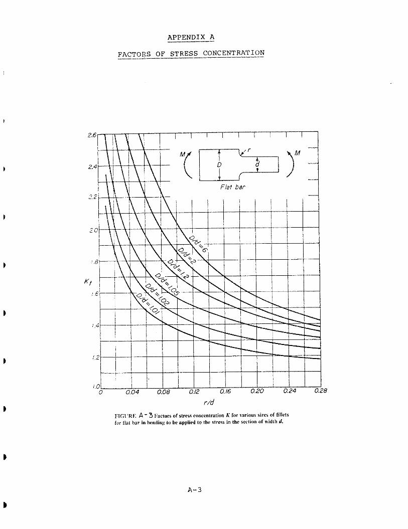
FIGURE 3. 1 Factors of stress concentration K for vsrious sizes of fillets for mmd bar in beding to beapplied to tbestresr in thesection ofdismeterd.
Let's look at an example and determine what the
actual stress concentration factor is:

The minor diameter (d) of a counterweight sheaue shaft is 2 2 inches, the major diameter (D) is 2 4
inches, and the radius of the fillet (r) is the
maximum allowable based on the geometry, 1 inch
Therefore. D/d = 1 . 0 9 and r/d = 0 . 0 4 5 . Using Figure
3 . 1 the stress concentration factor is 1 . 8 8 .
If we are to maintain the implied factor of safety included in the specifications then the allowable
stress for the sheave shaft should be reduced to 74
percent of the ualue listed in Rrticle 2 . 5 . 1 1 .
Now let's look at the sample problem b u t this time let the fillet be equal to 1 / 2 inch. D/d is still
equal to 1 . 0 9 but r/d = 0 . 0 2 3 . Again using Figure
3 . 1 the stress concentration factor is now 2 . 2 3 .
Since K is greater than 2 , the factor of safety t against fatigue failure is less than one. Which
means the shaft will last less than 1,000,000 cycles.
Assuming that the counterweight sheaue shaft is machined from a steel that has fatigue curves as
shown in Figure 3 . 2 and the shaft is designed for a
maximum allowable stress equal to 2 0 percent of the
ultimate or 1 8 ksi, then for the case where the
fillet is 1 inch the actual stress at the fillet,
taking into account the stress concentration factor,
is 3 3 . 8 ksi. However, for the shaft with a fillet radius of 1 / 2 inch the actual stress is 4 0 . 1 ksi. For a shaft with a machined finish from Figure 3 . 2
the shaft with the 1 inch radius should have a fatigue life of 1,000,000 cycles but the shaft with
the I/2 inch radius would have a fatigue life of only
2 0 0 , 0 0 0 cycles.

FIGURE 3.2 Typical fatigue m e s : steel specimens; reversed bending; s.,, 90,000 psi. Relationship between equivalent completely reversed stress el and fatigue life L.
If the sheaue shaft was for a uertical lift bridge
which opens twenty times a day, euery day per year
and each time the bridge opens the sheaue shaft
rotates through two complete reuolutions, then the
usefull life of the shaft would be greater than 50
years if the 1 inch fillet were used but less than 14
years if the 1/4 inch fillet were used.
It should be noted that the stress concentration
factors presented throughout this paper are based
strictly on the form or shape of the part and not on
the material or size. In reality the factor of
stress concentration for fatigue, which is the ratio
of the endurance limit of a plain specimen to the
nominal stress at the endurance limit of a specimen
containing a stress raiser, should be utilized to
more accurately depict the real life behavior.

The s t r e s s c o n c e n t r a t i o n f a c t o r f o r f a t i g u e n o t o n l y
depends on t h e shape o f t h e p a r t b u t a l s o t h e t y p e o f
m a t e r i a l , and t h e a c t u a l s i z e o f t h e p a r t . Methods
a r e a u a i l a b l e f o r making q u a n t i t a t i u e es t ima tes o f
t h e f a t i g u e s t r e s s c o n c e n t r a t i o n f a c t o r s b u t these
methods a re somewhat comp l i ca ted . The f u l l
t h e o r e t i c a l s t r e s s c o n c e n t r a t i o n f a c t o r s , as
p resen ted i n t h i s paper, a re e a s i e r t o determine and
a r e u s u a l l y l a r g e r t h a n t h e f a t i g u e s t r e s s
c o n c e n t r a t i o n f a c t o r s . There fo re , when t h e f a c t o r s
p resen ted h e r e i n a r e a p p l i e d , t h e r e s u l t s w i l l
u s u a l l y be on t h e sa fe s i d e .

4 . RECOMMENDED CHANGES TO ARTICLE 2 . 5 . d
From the preuious example, you can begin to see the importance that the details of a machinery part and the
associated stress concentration factors haue on the
seruice life of the component. For this reason it is
recommended that Article 2 . 5 . 1 1 be modified to stress the
importance of the details by prouiding ualues for stress
concentration factors, for the most common stress raisers.
The recommended change to this article is the addition of the following after the last paragraph of Article 2 . 5 . 1 1 :
"The actual stress concentration factor for uarious
details of machinery and other similar parts shall be
computed by utilizing the figures contained in Appendix
A . If the stress concentration factor determined from the
dppendix is less than 1 . 4 the ualues of allowable unit
stress tabulated in Article 2 . 5 . 1 1 may be utilized
directly. If the determined stress concentration factor
is greater than 1 . 4 then the allowable unit stress S k shall be utilized for the design.
Where: Sk = Reduced allowable unit stress Sa = Allowable unit stress tabulated
in Article 2 . 5 . 1 1
Kt = Stress concentration factor from
Appendix A . "
It is further recommended that the last sentence of
drticle 2 . 5 . 1 1 be deleted. This sentence reads, "In the

absence of keyways or other stress-raisers in a shaft, the unit stresses for torsion and flexure in a shaft may be
increased 20 percent." This prouision would be covered by
the proposed addition of the following paragraph.
"If the stress concentration factor determined from
appendix 6 is less than 1.4 the formula for S may be k
utilized to increase the allowable unit stress. But in no
case shall the stress concentration factor be taken as
less than 1.2."
Until a change is made to the Specifications it is
strongly recommended that all designers verify that the
details they utilize for machinery components do not haue
stress raisers with stress concentration factors exceeding
1.4.

1
5 . MODIFICATIONS TO THE AREA SPECIFICATIONS
The American Railway Engineering Association (AREA) Committee 1 5 recently approued a revision to the article
in the AREA Specifications, which is analogous to Article
2 . 5 . 1 1 i n the AASHTO Specifications. The reuision lowered
the allowable stress to 10,000 psi for trunnions with
rotation more than 180 degrees. The explanation given for
this change was that trunnions which rotate more than 180
degress experience full stress reversal, and that the
fatigue life of a trunnion is reduced by keyways,
shoulders and other section discontinuities.
The endurance limit for the two forged steels listed for
trunnions in the specification is approximately 30,000
psi. Trunnions designed in accordance with the
specifications would not experience stresses in excess of
30,000 psi, and therefore could not fail by fatigue,
unless they were overloaded by some unexpected occurrence
or a detail of the part created a locally high stress due
to a stress raiser with a high stress concentration factor.
This paper presents a different approach to handling an
apparent problem with the allowable stresses in
trunnions. Rather than reducing the allowable stress just
for trunnions, it is recommended that the modifications to
the specifications contained herein be adopted.

1. American Association o f State Highway and Transportation
Officials, "Standard Specifications for Mouable Highway
Bridges", Washington, D.C., 1978.
2. M.F. Spotts, "Design of Machine Elements", New Jersey,
Prentice - Hall, Inc., 1985.
3 . Raymond J . Roark and Warren C. Young, "Formulas for Stress
and Strain", New York, McGraw - Hill Book Company, 1975.

APPENDIX A -
FACTORS OF STRESS CONCENTRATION _____-____-_---
l..lGCRE A - l Factors of stress concentration K for various sizes of fillets for Hal bar in tension or compression to be applied to the stress in the section of ridlh d.

APPENDIX A
FACTORS OF STRESS CONCENTRATION ----
FIGURE A -2 Factors or stress concentration R for various sizes of fillets for round bar in tension or compression to be applied to the stress in the section diameter d.
APPENDIX --- A
FACTORS OF STRESS -- CONCENTRATION --- --
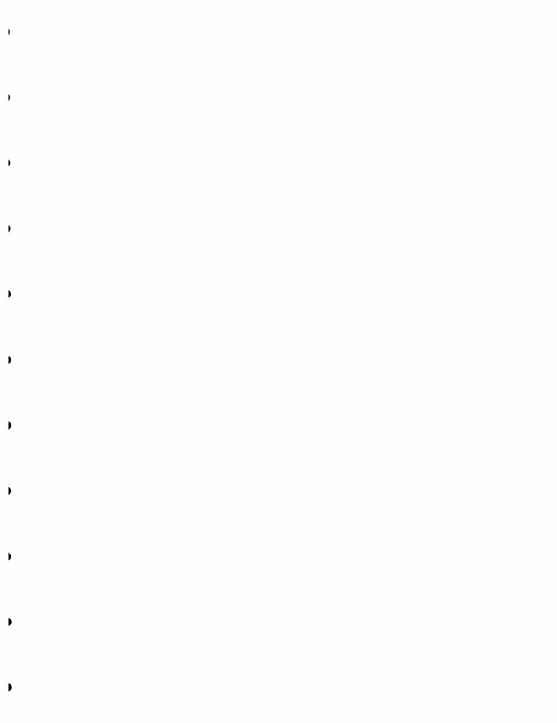
FICL'RE A - 3 Factors of stress concentration A' for various sires of fi11els for tiat bar in bendin:: 10 bc applied to the rtrms io the section of width d.
A P P E N D I X A -
FACTORS O F S T R E S S CONCENTRATION
APPENDIX A -
FACTORS OF STRESS CONCENTRATION
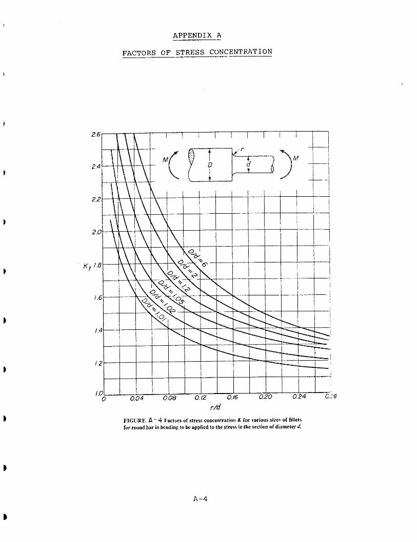
FIGURE A-5 Factors of stress concentration A' for grooves of various depths in tension or mmpression to be applied to the stress in the stction of the flat bar of width d.

A P P E N D I X A
FACTORS O F S T R E S S CONCENTRATION -
A P P E N D I X A
FACTORS O F S T R E S S CONCENTRATION -
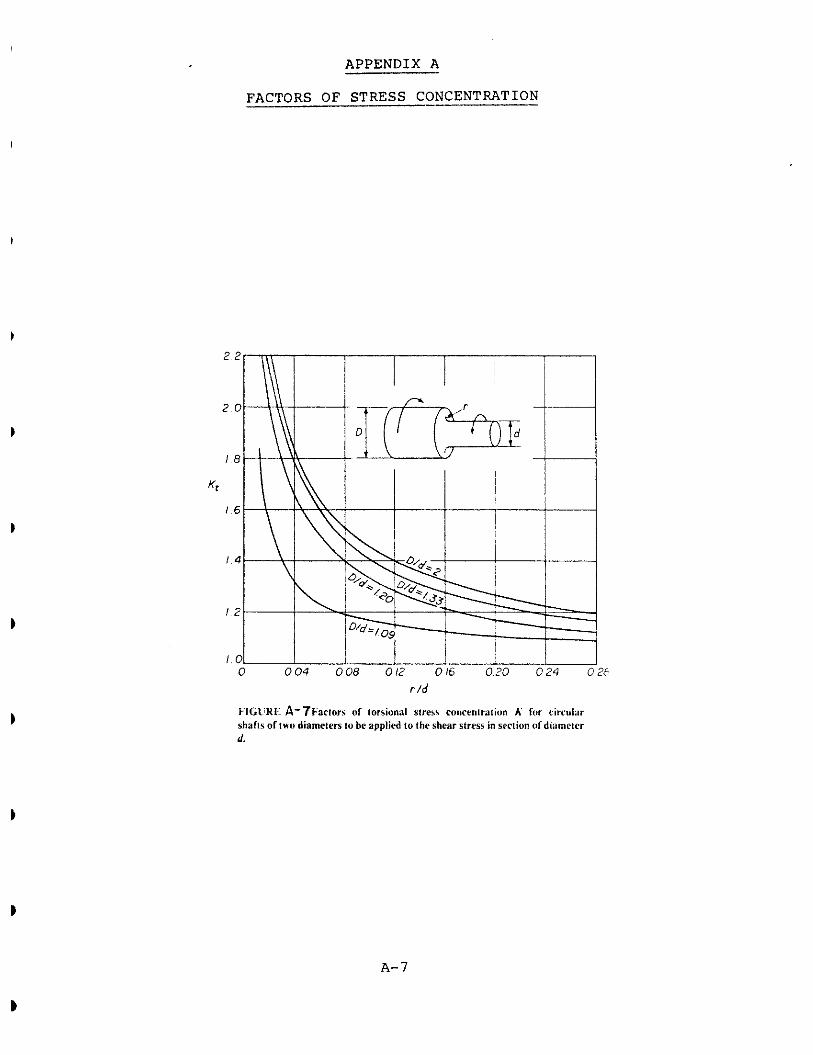
r / d
FIGI'HI: A-7Fartorr uf torsional stress conrentration E: for circular shafts of two diameters to be applied lo the shear strear in section of diamctcr d.
APPENDIX A
FACTORS OF STRESS CONCENTRATION
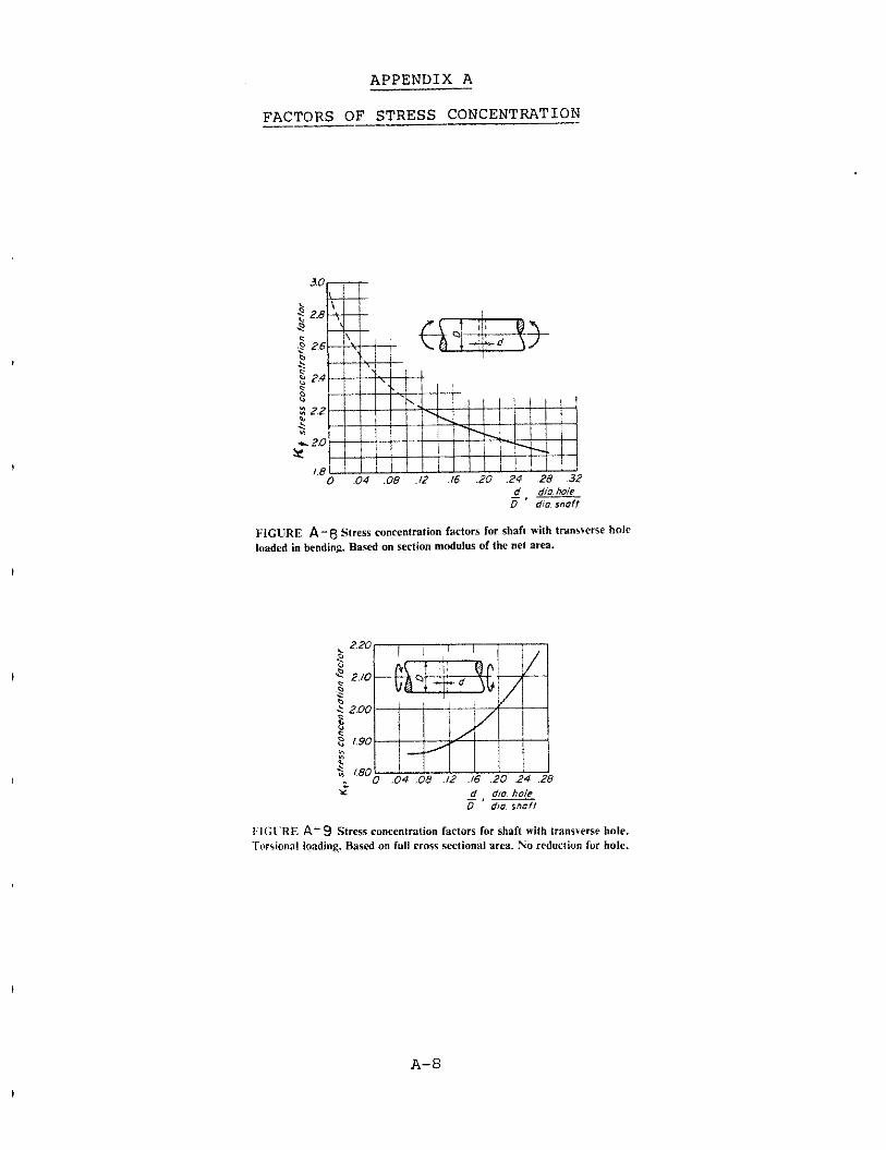
FIGCRE A-8 Stress concentration factors for shaR nith transverse hole loaded in bending. Bared on section modtrius of the net area.
d dm hole - . - 0 dm snaO
I'IGCRE A- 9 Stress ronrentntion factors far shaft with lrans+erse hole. Tor\ional loading. Bared on full crass ~cctiondl area. No reduction fur hole.