Recommended Practice for Precast Prestressed · PDF fileSpecial Report Recommended Practice...
43
Special Report Recommended Practice for Precast Prestressed Concrete Composite Bridge Deck Panels Prepared for the PCI Bridge Producers Committee by Ross Bryan Associates, Inc. Nashville, Tennessee Based on the latest research and field experience, this PCI Committee report presents recommendations for the design, production, handling, shipping and erection of precast prestressed concrete composite bridge deck panels. The report also covers product tolerances, cracking and repair methods, as well as plant and jobsite inspection procedures. A design example, using the AASHTO Specifications, is included together with several design aids. PCI JOURNAL, March-April 1988 $7
-
Upload
phungkhanh -
Category
Documents
-
view
238 -
download
2
Transcript of Recommended Practice for Precast Prestressed · PDF fileSpecial Report Recommended Practice...

Special Report
Recommended Practice forPrecast Prestressed Concrete
Composite Bridge Deck Panels
Prepared for the
PCI Bridge Producers Committee
byRoss Bryan Associates, Inc.
Nashville, Tennessee
Based on the latest research and field experience,this PCI Committee report presents recommendationsfor the design, production, handling, shipping anderection of precast prestressed concrete compositebridge deck panels.The report also covers product tolerances, crackingand repair methods, as well as plant and jobsiteinspection procedures.A design example, using the AASHTO Specifications,is included together with several design aids.
PCI JOURNAL,March-April 1988 $7

CONTENTSNotation........................................... 70
Introduction.......................... ............. 72
Chapter1—General ................................. 731.1 —History1.2 — Materials1.3 — Advantages1.4 — Design Considerations
Chapter2 — Design ................................. 752.1 — General Information2.2 - Panel Thickness and Size of Prestressing Strand2.3 — Strand Location2.4 — Factored Moment Strength and Strand Development2.5 — Panel Width and Span2.6 — Stress Transfer and 28-Day Strengths2.7 — Corrosion Protection2.8 — Fatigue2.9 — Strand Projections2.10 — Bearing Systems
2.10.1 —General2.10.2 — Temporary Bearing2.10.3 — Permanent Bearing2.10.4 — Installation Profile
2.11 — Load Distribution2.12 — Composite Behavior
Chapter3 — Manufacture ............................ 823.1 — Forms3.2 — Strand Positioning3.3 — Strand Surface Condition3.4 — Concrete Work3.5 — Curing3.6 — Detensioning Procedures
68

3.7 — Stripping
3.8 — Storage
Chapter 4 — Product Tolerances, Cracking and
DamageRepair .....................................844.1 — Tolerances
4.2 —Cracking
4.2.1 — Types of Cracking
4.2.2 — Repairs
Chapter 5 — Shipping and Handling ................... 86
5.1 — Panel Length and Width
5.2— Support on Trailers
5.3 — Multiple Panel Handling
5.4 — Jobsite Storage
Chapter6 — Erection ................................ 87
6.1 — Panel Handling
Chapter7 — Inspection .............................. 87
7.1 — Plant Inspection
7.1.1 —Forms
7.1.2 — Strand Position
7.1.3 — Strand Surface Condition
7.1.4 — Detensioning
7.1.5—Stripping
7.1.6 — Post-Pour Inspection
7.1.7 — Storage and Preshipment Inspections
7.2 — Jobsite Inspection
7.2.1 — Unloading Inspection
7.2.2 — Temporary Storage
7.2.3 — In-Place Inspection
References......................................... 89
AppendixA — Design Example ........................ 91
Appendix B — Sample Design Curves .................. 98
PCI JOURNAUMarch-April 1988 69

NOTATIONA – area (in,') of concrete at time ofA*. = area of prestressing initial prestress (psi)
steel (in. 2 ) fed = concrete stress at cen-b = unit width of deck ter of gravity of pre-
panel (in.) stressing steel due tob, = effective width of top all dead loads except
slab (in.) dead load present atchottam = distance from cen- time prestressing force
troidal axis to bottom is applied (psi)of deck panel (in.) f,. = concrete stress at cen-
CR, = loss of prestress due to ter of gravity of pre-creep of concrete (psi) stressing steel due to
CR, = loss of prestress due to prestressing force andrelaxation of pre- dead load of memberstressing steel (psi) immediately after
c,opp,P,.,, = distance from cen- stress transfer (psi)troidal axis to top of f,. = modulus of rupture ofdeck panel (in.) concrete (psi)
d = distance from extreme Of8 = total prestress loss (psi)compression fiber to f = ultimate strength ofcentroid of prestress- prestressing steel (ksi)ing force (in.) f = effective stress in pre-
dz = square of distance from stressing strand aftercomposite section losses (ksi)centroidal axis to cen- f ;, = average stress in pre-ter of gravity of ele- stressing steel at ulti-ment being considered mate load (ksi)(in. 2 ) ftop = bending stress at top of
D = nominal diameter of cast-in-place top slabprestressing steel (in.) froPn„^ = bending stress at top of
= modulus of elasticity of deck panel (psi)concrete at time of h„ = thickness of deckstress transfer (psi) panel (in.)
E„rPe modulus of elasticity of I = gross section momentdeck panel concrete of inertia (in.)(ksi) ld = strand development
E, = modulus of elasticity of lengthprestressing steel (psi) lz = distance from end of
E ;4 , m – modulus of elasticity of prestressing strand tocast-in-place top slab center of deck panelconcrete (ksi) (in.)
ES = loss of prestress due to L = span length (ft)elastic shortening (psi) M = bending moment (lb-ft)
= bending stress at hot- Mro,f;„„ = continuous span bend-tom of deck panel (psi) ing moment (lb-ft)
f^ = compressive strength M« = moment causing flex-of concrete at 28 days ural cracking at section(psi) due to externally ap-
f^; = compressive strength plied loads
70

Merial = total bending momentat which section willcrack (lb-ft)
M fipsi . rrfr – service load moment tohe used for design(lb-ft)
MDL = bending moment re-sulting from deadloads (lb-ft)
M„ = nominal momentstrength of section
= bending moment nec-essary to overcomeprestress force (lb-ft)
M j mpl. = simple span bendingmoment (lb-ft)
M. = factored moment atsection -- 4M,, (lb-ft)
n = modular ratio of elas-ticity
p* = ratio of prestressingsteel,A alhd
Poll Wwr = assumed effective pre-stress force per strandafter all losses (kips)
S = effective span lengthas defined under"Span Lengths" Arti-cle 324.1 of AASHTOSpecifications (ft)
SH = loss of prestress due to
concrete shrinkage(psi)
S boftom = section modulus ofcomposite section withrespect to bottom ofdeck panel (in.-)
Sbnrinm p,t mbare"- section modulus ofuntopped deck panelwith respect to itsbottom (in.3)
S t.p = section modulus ofcomposite section withrespect to top of com-posite slab (ins)
Stop,, e'us, = section modulus ofcomposite section withrespect to top of deckpanel (in.')
S ^a r , rP = section modulus of un-topped deck panel withrespect to its top (in.:')
W = uniform load (psi)Y = distance from bottom
of section to center ofgravity of elementbeing considered (in.)
Yroa = distance from cen-troidal axis of compos-ite section to extremefiber in compression(in.)
PCI JOURNAL/March-April 1988 71

INTRODUCTIONPrecast and prestressed concrete
composite bridge deck panels are usedwith cast-in-place concrete to provide aconvenient and cost effective method ofconstruction for concrete bridge decks.The panels are usually precast at amanufacturing plant. They are truckedto the bridge construction site and liftedby cranes onto concrete or steel girders.There, they span the opening betweengirders and serve as permanent forms forthe cast-in-place concrete topping thatcompletes the bridge deck The precastconcrete panels and concrete toppingbecome composite and the panels con-tain all of the required positive momentreinforcement between girders.
Precast and prestressed concretecomposite bridge deck panels will hereferred to, in this report, as "compositedeck panels" or simply as "deck panels."
Composite deck panels are similar toother prestressed concrete compositemembers with regard to applicationsand design considerations, There are,however, situations that are unique tocomposite deck panels due to the waythe panels are produced and used.
A 1986 survey conducted by the Pre-stressed Concrete Institute (PCI) con-tacted all State Highway Departmentsin the United States, numerous Tollwayand Transportation Authorities and PCImember plants to determine currentspecifications and methods of produc-tion. Some agencies have unique ap-proaches to the design and use of com-posite deck panels. Similarly, a fewmanufacturers have developed theirown methods for fabrication of theseproducts, A review of the survey re-sponses, however, reveals that there isuniformity between most agency speci-fications and prevalent methods of pro-duction.
The purpose of this report is to pre-sent recommendations for the design,manufacture and use of composite deckpanels. These recommendations aresupported by the referenced research,the analysis of the survey data, and thecollective experience and judgment ofthe precast and prestressed concrete in-dustry. The practices suggested in thisreport, where identified in use, havebeen shown to be performing favorablyin locations across North America, for aslong as 35 years. The recommendationsreported herein may be applied confi-dently by designers, precasters andcontractors with the expectation of ex-cellent performance for lowest possiblecost.
This report was prepared by RossBryan Associates, Inc. of Nashville,Tennessee, with input and directionfrom the PCI Bridge Producers Com-mittee, the PCI Committee on Bridgesand the Technical Activities Committee.All reasonable care has been used toverify the accuracy of material containedin this report. However, the reportshould be used only by those experi-enced in structural design and shouldnot replace sound structural engineer-ing judgment.
This report is intended to address de-sign, fabrication, shipping, handling,and erection requirements for precastprestressed concrete composite bridgedeck panels. All designs herein conformto the 1983 AASHTO Standard Specifi-cations for Highway Bridges, includingthe 1984 through 1987 Interim Specifi-cations.'
For the fabricator and the contractor,this report is intended as a guide for theproduction of high quality compositedeck panels and their proper installa-tion.
72
1.1 HistoryComposite deck panels are widely
used in the construction of bridges inthe United States. The 1986 survey con-ducted by PCI indicated that twenty-one State Highway Departments andthree Turnpike Authorities havespecified the use of composite deckpanels.
The panels were first used in the early195Os for construction of bridges on theIllinois TolIway. A number of statesbegan to use the panels in the late1960s and early 1970s. Also, several re-search projects were undertaken andcompleted during that time. 2- 11 The re-sults of that research along with earlierdesign experience form the basis forcurrent design practice.
The earliest installations of deckpanels are nearing 35 years of age, andthe panels are performing well. 7 In morerecent years, isolated problems havebeen reported, especially cracking inthe composite top slab and excessivebowing of deck panels prior to installa-tion. It was these concerns thatprompted the producer and user surveyand has resulted in this recommendedpractice report. These problems and therecommended solutions are discussedin this report.
Additional historical information, ref-erences and photographs may be foundin the special state-of-the-art report,"Precast Prestressed Concrete BridgeDeck Panels," prepared by the PCICommittee on Bridges."
1.2 MaterialsComposite bridge deck panels are
typically cast using low slump concretemixes. The use of water reducers andplasticizers are sometimes specified inorder to attain the required stress trans-fer and 28-clay strengths. Some agenciesspecify the use of rust or corrosion in-
hibitors in the mixes; however, mostrely on the cast-in-place top slab to pro-vide sufficient cover to prevent chloridepenetration into the composite deckpanels. Requirements for air entrain-ment in the composite deck panels vary.
The types of aggregates used varywidely across the country. Aggregatesize should be no larger than 3/4 in, toensure that concrete is thoroughly con-solidated below the strand in the shal-low pan forms and to achieve concretestrengths specified.
Strand used in deck panels includesnearly every size and type of strand pro-duced. Trends now are toward the use of% in. diameter strand. The practice ofstrand use varies depending on consid-erations of strand development lengths.
Typically, mild steel reinforcement isGrade 60 steel or welded wire fabric.
1.3 AdvantagesCommon bridge deck construction
consists of prestressed concrete girdersor steel girders supporting a roadwaydeck. This deck can be formed as a fulldepth cast-in-place slab or it can be con-structed using precast prestressed com-posite bridge deck panels as shown inFig. 1.
lithe bridge deck is cast in place forits full depth, forms must be installedand later removed. Forming costs arehigh and the installation and removal offorms is time consuming. In some situa-tions this creates safety hazards to trafficunder the construction or to the workersthemselves. Stay-in-place metal formsare sometimes used. These also elim-inate the need for form removal, butthey are subject to long term corrosionand do not replace or reduce the bottomreinforcement as they do not act com-positely with the concrete slab.
Precast prestressed concrete compos-ite bridge deck panels eliminate theneed for most of this expensive forming
PCI JOURNAUMarch-April 1988 73

CAST-IN-PLACE TOP SLAB
DECK PANEL
CAST-IN-PLACE TOP SLAB
p o- ^^ II.. II^'
DECK PANEL
Fig. 1. Typical details of deck panels on prestressed girder(top) and steel girder.
operation. The deck panel and cast-in-place top slab act compositely and resultin a significant material and cost sav-ings. The prestressing strands in thedeck panels provide the necessary bot-tom reinforcement in the composite slabsystem. This eliminates the need for onelayer of mild steel reinforcement in thedeck. The deck panels are manufacturedwith dense, high strength concrete thatis more resistant to chloride penetration.Because the deck panels are pre-stressed, the designer has the ability tocontrol stresses in the important tensilestress zone.
Composite bridge deck panels aremanufactured in established plantswhere proven production and qualitycontrol methods result in a productwhich conforms to specifications_ Mil-
lions of square feet of precast pre-stressed concrete composite bridge deckpanels have been manufactured and in-staIled. They have proven to be a soundeconomical alternative to conventionalforms and are usually chosen for con-struction when specifications permitalternate solutions.
1.4 Design ConsiderationsThe design of precast prestressed
concrete composite bridge deck panelsmust include an analysis of the panelsfor stresses due to handling and duringconstruction as well as ultimate strengthof the composite section.
Design drawings should show everyaspect of production and installation ofthe composite deck panels, including
74

storage instructions, bearing details, andall other special considerations.
Shop drawings prepared by the fabri-cator must include all information con-tained on the design drawings as well asany special information necessary forproduction. Composite deck panellengths should be carefully selectedwith consideration given to tolerancesfor girder horizontal sweep in order toachieve proper bearing.
When composite deck panels are usedon steel or prestressed concrete girders,the designer should recognize that shearstuds on steel girders and projectingstirrups on concrete girders must be lo-
cated to minimize interference withcomposite deck panel placement.
Torsional stresses are typically not in-duced in composite deck panels inbridges with straight girders. Torsion indeck panels due to girder movementshould be considered in the designwhen composite deck panels are usedon bridges with horizontally curvedsteel girders or box sections. These arespecial cases which should be carefullystudied.
Stresses from differential movementof long, relatively flexible steel girdersshould also he evaluated by the bridgedesigner.
CHAPTER 2- DESIGN
2.1 General InformationThe design of precast prestressed
concrete composite bridge deck panelsis based on the requirements in theStandard Specifications for HighwayBridges published by the American As-sociation of State Highway and Trans-portation Officials (AASHTO).'
As with prestressed concrete mem-bers in general, composite deck panelsare checked for transfer stresses, han-dling stresses, service load stresses, andfactored strength in shear and flexure.
Research has shown that compositedeck panels as presently designed per-form well under fatigue test conditions,and therefore no special provisions areneeded for fatigue. 2-6 Strand slippage isnot a common problem and tolerancesfor stressing forces as established byspecifying agencies are enforced.
Although precast prestressed concretecomposite deck panels have been usedwith success for many years, concernsrelating to their production and use, aswell as differences between agenciesspecifying the products, have raisedsome questions. This chapter addressesthose questions and evaluates their ef-
feet on design of the composite deckpanels.
2.2 Panel Thickness and Size ofPrestressing Strand
Panel thicknesses commonly used forcomposite deck panels have rangedfrom 2'/s to 4½ in. The panels should bemade as light as practicable for handlingpurposes, but this must be eva]uatedconsidering the potential for damage ifthe sections are too thin.
The recommended minimum com-posite deck panel thickness for generaluse is 3 in. The panel thickness is animportant factor in choosing the size ofstrands to be used. The relationship ofpanel thickness to strand diametershould be approximately 8:1 as shownbelow. This has been reported to givevery satisfactory results.
Panel Thickness Maximum strand size
3 in. % in,3V2 in. The in.
4 in. or larger ½ in.
The absolute minimum composite
PCI JOURNALMarch-April 1988 75

deck panel thickness should be 2½ in.Panels with this thickness, however, re-quire special care during manufactur-ing, handling, and erection. With % in.strands, the resulting clear concretecover is 1'i in. Article 9.25.1.2.2 of theAASHTO specifications requires 1 in.minimum cover on prestressing strandsin the bottom of slabs. Full scale tests ofbridges with composite deck panels in-dicated that 1 in, of concrete cover onthe strands in the panels was adequate.,,
Deviations from this recommendationare possible, but consideration must hegiven to the possibility of splitting of thepanel ends due to prestress transferforces. Use of thin panels or largestrands may require special end zonereinforcement, Deviations should besubmitted to the specifying agency forapproval.
2.3 Strand LocationThe majority of composite deck
panels produced over the years havehad strands located at the centroid of thesection although eccentric prestressingcan result in significant cost savingsover concentric prestressing.
Uniform spacing of the prestressingstrands is recommended to preventsplitting cracks in the panels.' Approxi-mately equal strand patterns may beused where equally spaced strand pat-terns do not coincide with the compositedeck panel width or jacking headerspacing. "a
2.4 Factored Moment Strength andStrand Development
Article 9.27 of the AASHTO Specifi-cations provides a relationship fordetermining the development length ofprestressing strand:
Development length:
td = (f – %f,)D (9-32)
where f ,, is the average stress in the pre-
stressing steel at ultimate load.The term f also occurs in the equa-
tion for factored moment strength, Mu,.Article 9,17.2, Eq. (9-13). However, thevalue of J' may not always he the sameas applied to these two equations. Thereason for this is that when short lengthdeck panels are used, there may not heenough total length available to developthe full strength of the prestressingstrands.
Article 9.17.4.2 states that the maxi-mum value for f at ultimate load belimited to:
f eu = l= + % f (9-19)D
where the term 1 r is the distance fromthe end of the prestressing strand to thecenter of the panel. In other words, astrand can develop a maximum value forf [Eq. (9-17) ] if the full developmentlength, 1 d , is available. When l ,x is lessthan l d , the maximum stress in thestrand will be correspondingly less.This will consequently reduce the valueof f,*,+ and the design flexural strength,M.
This is demonstrated graphically inFig. 2. The prestressing reinforcementshown for this panel is insufficient for aspan of less than about 5 ft. This is be-cause the allowable f has been signifi-cantly reduced due to the small value ofl. At a span length of just over 5 ft thereduction of f * is at its most criticalpoint, but as the span increases, theamount of the reduction becomes lesscritical because M„ is increasing muchfaster than the factored moment. For thisreason, in deck panels with longerspans, the formation of some splittingcracks or damage resulting from han-dling at the ends should not necessarilybe a cause for rejection. See the recom-mendations concerning cracks in Sec-tion 4.2.1.,
This subject of reduced values for fv*„
is illustrated in the design example inAppendix A:
76

40 Additional reint.required due to < 100% of aj used to calculate 100% of f R used to
r dIon in 1 su by capacity because of embedment calculate flexuralAASHTO equation length but panel has adequate strength .9-19. flexural strength.
30CIS : 1.0 Design FlexuralTopping Thickness : 4 in. Strength
I Topping Strength At 28 Days : 4500 psi M„ 1aAllowable Tension : 212 psi
I- 20 - Nominal Diameter Of Strand : 3/8 in.z Deck Panel Thickness : 3 in.M02 1-2 x Cra king Moment
10 -
Factored Moment
DECK PANEL SIMPLE SPAN (FT.)
Fig. 2. Moment capacity versus requirement with respect to span.
10
= 257 ksi [Eq. (9-17) unreducedvalue]
= 180 ksiD = 0.375 in.
Substituting these values into Eq.(9-32) gives:Development length, 1,:
= [257 – (%)(180)1(0.375)= 50.1 in.
In the design example, a reduction inf az was made from 257 to 243 ksi in com-pliance with Article 9.17.4.2. This re-duction was a function of the distancefrom the end of the prestressing strandto the center of the panel (l x ). In order touse the full value off * to calculate de-sign flexural strength, the developmentlength in this example must be 50.1 in.As can be seen, even when f ** was re-duced, the design flexural strength wasgreater than the actual required. Thisreveals that development length is notcritical for the majority of spans.
Results of research on developmentlength vary substantially. Tests con-
ducted on different size strands haveshown that average developmentlengths of22 in. for % in. strands, and 34in. for '/a in. strands are required.'."Kluge recommends a 62 in. develop-ment length for 3 in. strands.$
Although many values are below, andsome are above, the AASHTO Specifi-cation requirements, the results are notconclusive enough to justify anyrecommended changes to these re-quirements.
2.5 Panel Width and SpanComposite deck panels have been
fabricated with widths ranging from 2 ft
to as much as 10 ft, with 4 and 8 ft beingthe most common.
Decisions about panel width shouldinvolve discussions with the fabricatorand contractor concerning the advan-tages and disadvantages of wide versusnarrow composite deck panels. Widerpanels afford more effective use offorms. They also permit stripping and
PCI JOURNAL^March-April 1988 77
handling to proceed more rapidly be-cause there are fewer pieces to handle.
Preferred composite deck panelwidths are 4 and 8 ft. Two foot widepanels may he used at edges or wherenecessary due to bridge geometry.Trapezoidal or triangular pieces may beused at ends on skewed bridges.
The composite deck panel spanlength is selected by the designer basedon girder spacing. Deck panel spans canvary and are influenced by deck panelthickness, cast-in-place slab thickness,superimposed loads, and required pre-stress force.
2.6 Stress Transfer and 28-DayStrengths
Article 9.22 of the AASIITO Specifi-cations requires a minimum concretestrength at the time of stress transfer of4000 psi. Article 9.15 indicates designsare based on a 28-day minimum com-pressive strength of 5000 psi. Thesestrengths are routinely reached in panelproduction.
2.7 Corrosion ProtectionCracks which form in the cast-in-place
top slab have not been observed to ex-tend to the deck panels (see Section2.11). Research conducted by the TexasTransportation Institute' indicatedthese cracks did not occur in the testbridges until several months after con-st-action. The cracks most likely formeddue to shrinkage and thermal effects.Cores taken after ultimate load tests ofthe structure indicated the averagedepth of the cracks was approximatelyone-half the depth of the cast-in-placetop slat). Another study2 also pointedout the importance of ensuring propercuring methods for the cast-in-placeslab.
The use of corrosion inhibiting ad-mixtures or epoxy coated reinforcementin the deck panels is generally notnecessary.
2.8 FatigueResearch indicates cyclic loading up
to 11 million cycles had no detrimentaleffect on the long term performance ofprecast prestressed concrete compositebridge deck panels.2,3,,, an
Special attention is therefore not re-quired in the design of composite deckpanels for fatigue, However, cyclicloading should be considered in re-viewing details for permanent bearings.Proven systems such as those describedin Section 2.10 should be used.
2.9 Strand ProjectionsResearch indicates that the overall
behavior of bridges with and withoutdeck panel strand projections is verynearly the same. a," The most importantfactor is adequate bearing for the panelson the bridge girders. The use of strandprojections is not an acceptable sub-stitute for good bearings. In many cases,strand projections contribute a sub-stantial cost component by inhibitingthe production of deck panels by longline casting and saw cutting. Therefore,it is recommended they not be used.
2.10 Bearing Systems
2.10.1 GeneralOne of the most important compo-
nents of a bridge constructed using pre-stressed composite deck panels is bear-ing of the deck panel on the bridgegirder.
Composite bridge deck panels mustbe supported on the bridge girders by apermanent bearing material providingcontinuous and solid support and con-sisting of mortar, grout, concrete orsteel. 6 Research conducted on bridges inFlorida, 15.t which used only a soft fi-brous material as the final bearing underthe ends of the deck panels, indicated:
(a) The overall bridge deck behavedmore like simple spans than acontinuous slab over the stringers.
(b) The ends of the composite deck
78

Fig, 3. Dimensions of temporary bearings for supporting deck panels.
panels delaminated from thecast-in-place topping, forcing thetopping alone to carry the liveload shear.
(c) The majority of these bridges de-veloped extensive cracking.Bridges with this hearing detailwill have a reduced service life.?
2.10.2 Temporary BearingIi grout or concrete is used as per-
manent bearing material, the compositedeck panels must he supported abovethe bridge girders by a temporary bear-ing system. The temporary bearing sys-tem provides support for the panels dur-ing erection and until the grout or con-crete reaches design strength. The tem-porary bearing system may be designedto be removed or may remain in place.
Removable systems include wood
planks and steel angles or channels at-tached to the sides of the bridge girders.These supports are removed after thecast-in-place top slab reaches designstrength.
Temporary systems designed to re-main in place include continuous stripsof compressible material such as ex-panded polystyrene, fiberboard, orbituminous fiberboard, Unyieldingmaterials such as steel or hard plasticshims, which are left in place aftergrouting, will continue to provide theprimary support for deck panels shouldthe permanent grout or concrete bearingmaterial shrink. This will result inundesirable cracking in the bridge deckslab over these rigid bearing points.Therefore, temporary bearing materialswhich are designed to remain in placemust be compressible.
PCI JOURNALJMarch-April 1988 79

Proper performance of the finisheddeck requires that the height of the tem-porary bearing material he adequate toallow grout or concrete to flow easilyunder the deck panel overhang. Thisshould be a minimum of I in. whengrout is used. The vertical clearanceshould be increased to a minimum of 11/zin. if the top slab concrete is to flowunder the deck panels to provide per-manent support (see Fig. 3). The tops ofsupporting girders must be smoothenough to allow the grout or concrete toflow readily. The composite deck panelsmust extend a minimum of 1 1/2 in. be-yond the temporary bearing material.
Compressible bearing materials willindeed be compressed due to the weightof the deck panel. This decrease invertical clearance must be accounted forin sizing the temporary bearings.
2.10.3 Permanent BearingWhen composite deck panels were
first used, they were supported on con-tinuous hand placed mortar beds. Thismethod of support works well and is stillwidely used. The mortar bed should bea minimum of 1 in, thick and 3 in. wide.The thickness can be controlled byusing small wooden or plastic pegs cutto the proper length acting as spacers.The spacers must be retrieved beforesetting deck panels so as not to providepermanent support when the mortarshrinks. Deck panels must he placed onthe mortar beds before the mortar hard-ens to ensure they have even support.
The use of grout, concrete, and mortarbeds for permanent hearings have beentested and found to perform satisfactor-ily through as many as two million ap-plications of simulated design axle loadwith impact.2•59 7
When flowable grout or concrete isused, venting is required to ensure thatfinal placement is not inhibited by airlock. This should be accomplished byleaving small gaps in the strips of com-pressible bearing material at a spacing
of approximately 36 in.If grout is used as the permanent
bearing material, it should he a highstrength, low slump cementitious groutor a nonshrink grout with a maximumcompressive strength of 5000 psi. Thestrength of the grout should be verifiedby tests prior to placement of the cast-in-place top slab.
If the top slab concrete is designed toflow under the composite deck panel forpermanent support, proper placementprocedures should be followed. Con-crete should he deposited in continuousstrips over the girders and allowed toflow under the ends of the compositedeck panels. Concrete should then beplaced on the remainder of the panels.This procedure improves the flow ofconcrete under the panel ends, helpseliminate air pockets, and places con-crete under the panels before the com-pressible temporary bearings are loadedwith the weight of the fresh concrete.
2.10.4 Installation ProfileThe contour of the roadway surface
usually does not follow the top surfacesof the girder. This is due to girdercamber, vertical curvature of the struc-ture, superelevation of the roadway, or acombination of these. To account forelevation variations, there are two op-tions to consider for support of the com-posite deck panels: (1) The compositedeck panels can have a constant, uni-form thickness permanent bearing (con-stant fillet) and therefore a variablethickness top slab, or (2) The compositedeck panels can have variable thicknesspermanent hearing (variable fillet) witha relatively constant top slab thickness.
The advantage of the constant filletoption is the relative ease of installationof the temporary or permanent bearingsystem. Disadvantages of this option in-clude the varying thickness of the top-ping, having the top slab reinforcingsteel not parallel with the roadway sur-face, or providing variable height chairs
80

to support the reinforcing steel parallelto the roadway surface. The variablethickness top slab uses a greater volumeof concrete. The cost associated withthis extra weight may be offset by sav-ings in the erection of the deck panelson constant fillet bearings. The addeddead load of the thickened portions ofthe slab should be taken into account bythe bridge designer in the design of thegirders and other elements of the bridgestructure. No research has been foundthat would indicate that performanceand service life of a bridge are adverselyaffected due to a variable thickness topslab.
The variable fillet system results in aconstant thickness bridge deck wherethe composite deck panels are parallelto the roadway surface and the rein-forcing steel. The installation of variablethickness bearing systems requirescareful dimensional control and issomewhat more difficult to accomplishthan constant fillet systems.
2.11 Load DistributionA subject of past and current research
has been the ability of this deck systemto distribute wheel loads in the direc-tion transverse to the strands in thecomposite deck panels. One questionhas been the effect of the joints betweenadjacent panels. Continuity at this jointis provided by the cast-in-place portionof the deck. Another question has beenthe quantity and location of reinforce-ment placed within the panel transverseto the strands.
Research results indicate that thepresence of the joint is not detrimentalto the load distribution performance ofbridge deck systems using compositedeck panels.' fi Tests have been per-formed with longitudinal (with respectto the bridge) distribution reinforce-ment placed directly on top of the com-posite deck panels.° Tests have alsobeen performed using supplementalreinforcement directly on the composite
deck panels across the joint in additionto the normal longitudinal reinforce-ment.2
Results of these tests demonstratethat the concrete top slab successfullytransfers wheel loads across the joints.The supplemental joint reinforcementdoes not improve performance. 2 In alltests performed with concentrated loadsplaced immediately adjacent to the buttjoint, the mode of failure was punchingshear.
Research performed in Texas 2 andFlorida indicates that even at failureloads there was no tensile cracking ob-served on the bottom of the cast-in-placetop slab directly over the butt joint. Thisdemonstrates the noncritical behavior offlexural strength across the joint.'
Research performed in Texas on in-service bridges s and in laboratory fullscale mockups 2 indicated a tendency forshrinkage and thermal cracks to form inthe cast-in-place top slab directly abovethe joint between adjacent compositedeck panels. The cracks extended downapproximately one-half the way throughthe top slab. The presence of thesecracks did not adversely affect the abil-ity of the slab to transfer wheel loadsacross the joints. 2 It therefore can beconcluded that the distribution rein-forcement in the cast-in-place top slabperforms better when placed toward thetop to control shrinkage and thermalcracking than when placed at the bottomof the topping in an attempt to controlflexural cracking. Reinforcement placedat the top of the slab also serves as dis-tribution reinforcement by providingsteel for cantilever action across thecomposite deck panel joints.
The distribution reinforcement in thecast-in-place top slab should be placeddirectly under the main transverse topflexural reinforcement.'' The main flex-ural reinforcement should he placedwith attention to minimum cover re-quirements in the AASHTO Specifica-tions.
In addition, research in Florida" was
PCI JOURNALJMarch -April 1988 81

conducted to determine reinforcingsteel requirements transverse to com-posite deck panel spans. Panels weretested under simulated concentratedwheel loads to failure. These failureswere attributed to punching shear atload levels many times design load. Thebasic conclusion of this research wasthat #3 bars at 12 in. centers (0.11in. 2lft) should be the minimum trans-verse steel requirement. The primarypurpose of this reinforcement is to com-pensate for the potential effect on stranddevelopment due to transverse tensilestrains resulting from two-way plate ac-tion.
A study was performed in Texas onin-service bridges. 5 The 3 in. thick com-posite deck panels had #2 bars at 6 in.centers (0.10 in. 2/ft) placed across thetop of the strands. There was no evi-dence that this level of reinforcementresulted in any detrimental effects onthe performance of the deck. However,the study was limited to widths of 4 ftand spans of 7 ft 3 in.
AASHTO has adopted the use of 0.11in. z/ft as the minimum reinforcement to
be placed in the composite deck paneltransverse to the strands. This level ofreinforcement has been shown to besatisfactory.
The placement of the transversereinforcement above the strands hasbeen satisfactory although the likeli-hood of cracking during handling is in-creased due to this steel being locatedabove the neutral axis, The placement ofthe transverse reinforcement, whetherabove or below the strands, should beleft to the discretion of the designer withdue regard to the minimum cover re-quirements of AASHTO.
2.12 Composite BehaviorMechanical shear connectors are not
necessary to achieve composite actionbetween the deck panel and the cast-in-place slah_ 3 " 11 Full composite action isachieved if the deck panel surface isroughened and is free of contaminants.Panels should be raked in the directionparallel to the strands in order to mini-mize the reduction in section mod-uIus. 2.13,14,18
CHAPTER 3- MANUFACTURE
3.1 Forms
The condition of forms used for cast-ing composite deck panels is of the ut-most importance to the quality of theproduct. Forms should be constructed ofsteel and properly designed to manu-facture this product. Side forms shouldbe constructed to eliminate productdamage at the time of stripping. Thismay be accomplished with side formswhich have a slight draft or which canbe loosened or removed.
Forms should be cleaned after eachpour to prevent a build-up of concrete.Forms should be scheduled for regularcleaning. The flatness of the form soffitshould be checked regularly to ensurethat the finished products meet required
tolerances (see Section 4.1). The formmay slope uniformly as necessary fordrainage.
Uneven forms and poor form condi-tion are two of the items that have beenreported as causes of problems such ascracking, incorrect strand position, anddamaged panels.
Excessive form temperatures at thetime of concrete placement should beavoided, The form should be shadedand/or cooled by spraying with water asrequired. Additional information maybefound in PCI MNL-116.'9
3.2 Strand PositioningDeck panels may be manufactured in
a form using headers between individ-
82
ual units or in a continuous length andsawn to the proper length.
In a process containing headers, themost effective means of maintainingstrand position is the use of accuratelymanufactured steel headers securelyfastened to the forms. Chairs should beused in forms containing headers wherethe strand position is not controlled ad-equately by the header. Strand positionin continuous panel forms withoutheaders is most effectively maintainedby the use of chairs located at sufficientintervals along the length of the bed.
It is important to note that in each ofthese situations the position of thestrand is a function of the contour of theforms. Further, whatever means is usedto position strands, it should be unaf-fected by the concrete placing opera-tion,
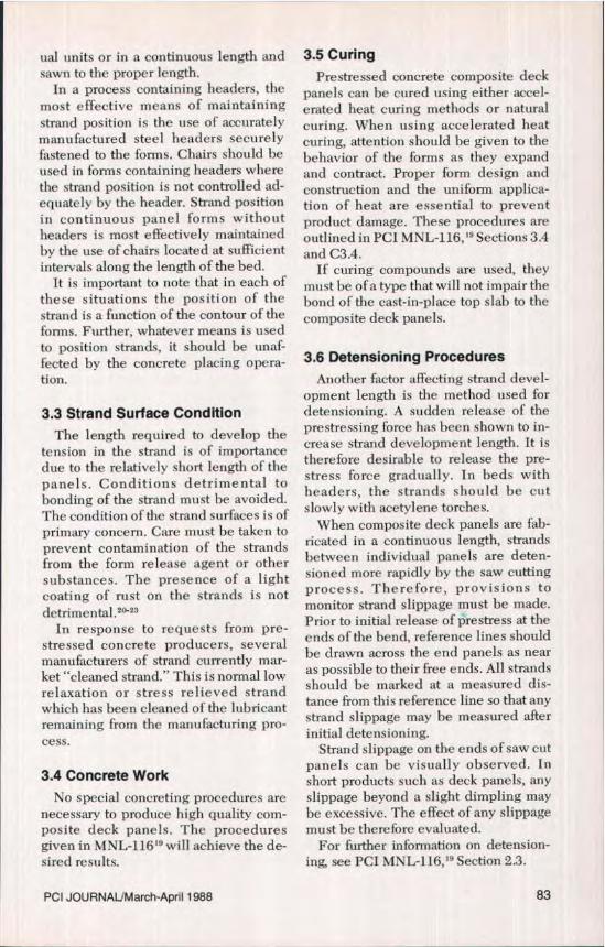
3.3 Strand Surface ConditionThe length required to develop the
tension in the strand is of importancedue to the relatively short length of thepanels. Conditions detrimental tobonding of the strand must be avoided.The condition of the strand surfaces is ofprimary concern. Care must be taken toprevent contamination of the strandsfrom the form release agent or othersubstances. The presence of a lightcoating of rust on the strands is notdetrimental.20-23
In response to requests from pre-stressed concrete producers, severalmanufacturers of strand currently mar-ket "cleaned strand." This is normal lowrelaxation or stress relieved strandwhich has been cleaned of the lubricantremaining from the manufacturing pro-cess.
3.4 Concrete WorkNo special concreting procedures are
necessary to produce high quality com-posite deck panels. The proceduresgiven in MNL-116' 9 will achieve the de-sired results.
3.5 CuringPrestressed concrete composite deck
panels can be cured using either accel-erated heat curing methods or naturalcuring. When using accelerated heatcuring, attention should be given to thebehavior of the forms as they expandand contract. Proper farm design andconstruction and the uniform applica-tion of heat are essential to preventproduct damage. These procedures areoutlined in PCI MNL-116, 19 Sections 3.4and C3.4.
If curing compounds are used, theymust be of a type that will not impair thebond of the cast-in-place top slab to thecomposite deck panels.
3.6 Detensioning ProceduresAnother factor affecting strand devel-
opment length is the method used fordetensioning. A sudden release of theprestressing force has been shown to in-crease strand development length, It istherefore desirable to release the pre-stress force gradually. In beds withheaders, the strands should be cutslowly with acetylene torches.
When composite deck panels are fab-ricated in a continuous length, strandsbetween individual panels are deten-sioned more rapidly by the saw cuttingprocess. Therefore, provisions tomonitor strand slippage must be made.Prior to initial release of prestress at theends of the bend, reference lines shouldbe drawn across the end panels as nearas possible to their free ends. All strandsshould be marked at a measured dis-tance from this reference line so that anystrand slippage may be measured afterinitial detensioning.
Strand slippage on the ends of saw cutpanels can be visually observed. Inshort products such as deck panels, anyslippage beyond a slight dimpling maybe excessive. The effect of any slippagemust be therefore evaluated.
For further information on detension-ing, see PCI MNL-116,' 1 Section 2.3.
PCI JOURNAUMarch-April 1988 83

3.7 StrippingSeveral methods are used to lift and
handle precast prestressed concretecomposite deck panels. Inserts or liftingloops near the four corners of the panelsare most often used. Stripping or liftingthe panels by attachment of lifting de-vices to strand projections must beavoided. A design review of any han-dling system is recommended.
3.8 StorageStorage areas must be smooth and
well compacted to resist settlement ofdunnage and resultant product damage.Stacks of deck panels should be sup-ported by continuous strips of dunnagedirectly on the ground perpendicular tothe strands near the ends. Intermediatedunnage between panels may he fulllength or provide support near all fourcomers. A template should be used to
locate the dunnage to ensure that sup-port throughout the stack is uniform andthe dead load of upper panels does notinduce any unwanted stresses intopanels stored below. Stacks of panelsshould be limited to a height that willnot cause settlement of the ground dun-nage or crushing of intermediate dun-nage.
Composite deck panels should bestored for the absolute minimum periodof time possible. Storage over the wintermonths requires special considerationsas freeze/thaw cycles may result in soilheaving and loss of stack levelness,which can result in product damage.Stacks may be supported on more rigidfoundations or shifted as needed whendunnage heaves. Panels with strandprojections should be oriented in amanner so projections are not subject todamage by vehicular traffic moving inai sleways.
CHAPTER 4- PRODUCT TOLERANCES,CRACKING AND DAMAGE REPAIR
4.1 TolerancesThe dimensional tolerances shown in
Fig. 4 are recommended for use byspecifying agencies and producers.Through careful production practice,these tolerances can be met and will re-sult in high quality products.
4.2 Cracking
4.2.1 Types of CrackingDue to the constitution of concrete,
any concrete product can experiencerandom cracking. Precast prestressedconcrete deck panels are no exception.
As with other types of products, theprimary question arising over crackswhich occur is to determine which onesare structurally significant. Most cracksin deck panels have no structural im-portance while some cracks indicate Ioss
of structural integrity. For the latter,methods of evaluation and repair arenecessary.
Due to the relatively short Iength ofcomposite deck panels, the most objec-tionable cracks are typically those thatwould increase the strand developmentlength with a resulting decrease inpanel capacity. In general, cracks thatwould indicate an increase in develop-ment length are:
1. Two cracks, each occurring within1 in. of two adjacent strands.
2. Corner cracks or breaks involvingtwo or more strands.
3. Cracks parallel to and along morethan 25 percent of the strands.
Cracks of these types can be a causefor rejection of composite deck panelsbecause the effective prestress force inthe panel may have been significantlyreduced.
84

e e
4-
a',cncj E 4, +34 in. -f'ori can oil tendon
} l4 in.
= ^ow/3roOC2in.Tnax)C = Thicknes (ncmncl acrras (rr 'vv t^3rr 3r,r^ y^zr d
panel) =t8 t^gin. cj.S}rcancIF ojecnQ^ +3ciirr.
d=Vertical terndan! ()iHunmcasurec from sc>fht
rverq e ot'• cii! ter dons
^ ° tbicii'. rOH4 it ).rdiviuc-a t-. ,cic>ns.
<C 'If;I-hicklt'$in.Thick;± ELI. 1r7.
h t unnciq Ioc hon_±Gn-
j _ +bri pr cil cil nmnf._4 inmcx.
k - Scauareness 1 in.max.l - ern.c nd lc r" l ;,minimum cover reclt„rementsmuss be m& on cU errands.
Fig. 4. Deck panel dimensional tolerances.
Cracks of less significance includeshrinkage and other cracks that are notin proximity to the strands. There are nospecific types of cracks which are de-fined as acceptable. Common practice isfor cracks to be evaluated on a panel by
panel hasis by qualified individuals.Because of the difficulty of evaluation, itis extremely important to use methods ofdesign and production which eliminateas many potential sources of cracking aspossible.
PCI JOURNAL/March-April 1988 85

4.2.2 RepairsAt the present time, the only univer-
sally accepted method of correcting re-pairable cracks in prestressed concrete
deck panels is epoxy injection. Crackswhich cannot be injected because oftheir very small size may he painted orcovered with epoxy.
CHAPTER 5- SHIPPING AND HANDLING5.1 Panel Length and Width
Composite deck panel lengths andwidths vary due to bridge geometry. Ingeneral, the wider and longer deckpanels are more susceptible to damageduring shipping and handling. Handlingstresses must be considered in the de-sign of the panels.
As with all precast elements, compos-ite deck panels should be handled in amanner consistent with their design.Panels should he handled only with ap-proved devices at designated locations.Long or wide panels may be handledusing normal equipment and tech-niques, but extra care must be taken dueto their increased size.
5.2 Support on TrailersComposite deck panels should be
loaded on trailers with dunnage locatedas described in Section 3.8. Care shouldbe used in securing the stacks to thetrailer to ensure that no excessive loadswill be induced in the members. Tie-down straps must fall over lines of dun-nage and protective blocking must beused to prevent damage to the panels.Banding of several panels together inboth directions has been used to elimi-nate shifting of panels and supports.
Damage to panels in transit has beenreported for stacks toward the rear endof trailers. For this reason, panel stacksmay be reduced to half the normal ship-ping height for the last 20 ft of the trailerlength.
Drivers and loading personnel shouldhe given instructions on proper methodsof support and correct tie-down proce-dures.
5.3 Multiple Panel HandlingGreat care should be exercised when
multiple panel handling is used. It isdifficult to support a stack of panels by amethod that does not induce undesira-hle stresses into the lower panels. Spe-cial support slings or strong hacks are re-quired to prevent overloading the lowerpanels. Methods for multiple panelhandling should be closely reviewed bya qualified engineer to ensure that nodamage will result from the multiplepanel handling method.
5.4 Jobsite StorageA common problem which results in
damage to composite deck panels is thelack of adequate storage areas at the job-site. An area should be prepared that iscapable of supporting stacked deckpanels without settlement of the groundcontact dunnage. Composite deckpanels are very easily cracked whenwarped due to uneven settlement ofdunnage. Section 3.8 describes recom-mended storage methods. The contrac-tor must be notified of the potential fordamage to panels if he fails to provide anadequate storage area.
Composite deck panels must not bestacked on previously erected deckpanels until the topping is cast and theseloads are evaluated by the designer. Iftemporary dunnage is placed on previ-ously erected panels, it must be placedover the supported ends of the panelonly after the permanent bearing systemis in place. Placing dunnage inboard ofthe end supports will induce high tlexu-ral and shear stresses which compositedeck panels were not designed to resist.
86

CHAPTER 6- ERECTION
6.1 Panel HandlingThe same care used in loading deck
panels at the plant must be exercised atthe jobsite for unloading. Equipmentdesigned for lifting these units shouldbe used. Front end loaders and othergrading equipment must not be substi-tuted for proper cranes.
Multiple panel stacks must not beplaced on girders unless it can be shownthat no damage to the panels or tempor-ary hearings will result. Composite deckpanels must be placed so they do notreceive support from portions of thebridge structure on which they were notdesigned to bear. Any support otherthan at the designated bearing locationscan result in damage to the compositedeck panel and poor performance of thetotal bridge deck system at that location.Composite deck panels placed so as tocompletely cover over diaphragms can
also cause difficulties in placing and vi-brating concrete in the cast-in-placediaphragms. 11.14
Construction loads imposed on indi-vidual panels must not exceed thesuperimposed design dead load capac-ity. Panels must not be used to supportbundles of reinforcement, heavyequipment, or concrete buckets. Untilthe top slab is cast and cured, the bridgedeck panels will not support heavy con-centrated loads.
During erection of the bridge girders,the composite deck panel lengthsshould be verified. The sweep tolerancein long girders may result in short bear-ing for panels which are the correct de-sign length,
All erection procedures should com-ply with the Recommended Practice forErection of Precast Concrete 23 whereapplicable.
CHAPTER 7- INSPECTION
7.1 Plant InspectionThorough and regular plant inspec-
tion during all phases of the manufac-turing process is one key to a successfulproject.
7.1.1 FormsComposite deck panel forms must be
inspected daily for cleanliness, align-ment, and general condition as outlinedin Section 3.1.
7.1.2 Strand PositionStrand position must be verified prior
to placing concrete. This can easily beaccomplished with the use of a gage de-signed to check the space between thestrands and the form_ Measurementsshould be made to verify that the chairs
or headers are maintaining the properstrand position. Chairs can deform dur-ing concrete placement or allow a strandto sag if the spacing is too great.
7.1.3 Strand Surface ConditionInspection must verify that the strand
surfaces are clean just prior to casting. Ifcontamination exists, the strands mustbe thoroughly cleaned with an effectivesolvent. This is very difficult to do ade-quately, so the emphasis must be oneliminating sources of contamination. Alight coating of rust on the strand is ac-ceptable.
7.1.4 DetensioningInspection procedures at the time of
detensioning primarily consist of verifi-
PCI JOURNAUMarch-April 1988 87

cation that the method used is onewhich has been tested and approved.The required concrete strength neces-sary for stress transfer must be attainedbefore detensioning and must be veri-fied by the use of concrete cylindertests.
7.1.5 StrippingComposite deck panels should be in-
spected for damage at the time of strip-ping. The inspector should also observethe means by which the panels arestripped from the form and the methodsof handling.
7.1.6 Post-Pour InspectionA complete post-pour inspection must
be made within 24 hours of the time ofprestress release. This inspection mustcover any deficiencies in the product'sphysical dimensions, and must giveparticular attention to any cracks orneeded repairs.
7.1.7 Storage and PreshipmentInspections
After the composite deck panels havebeen stripped and have received apost-pour inspection, they are generallyremoved to a storage area. Periodicchecks of panels in storage must hemade to ensure that blocking is properlylocated and that no settlement in thestacks has occurred. Any damage ob-served should be evaluated for remedialaction. Due to the potential for damagefrom settlement of dunnage or vehiculartraffic, panels must be reinspected at atime just prior to shipment. This willprovide documentation to show that thepanels did not leave the producer'sfacility in a damaged condition.
7.2 Jobsite InspectionProducer follow-up with inspection
and information at the jobsite is the sec-ond key toward success in these proj-ects.
7.2.1 Unloading InspectionAn inspection of the panels at the job-
site should be made during unloading.This inspection will determine if anydamage has occurred during shipmentof the panels to the jobsite. This willalso provide documentation to show thatdamage discovered later probably re-sulted from mishandling of, or impropersuperimposed loads on, the products atthe jobsite.
7.2.2 Temporary StorageTemporary storage of the composite
deck panels must be reviewed at thejobsite to ensure that an adequate areahas been prepared. This storage areashould meet the same requirements de-scribed in Section 3.8.
7.2.3 In-Place InspectionComposite deck panels should be in-
spected after erection to document thatno damage occurred as they were placedin their final position. Attention must begiven to the hearing details to ensurethat the composite deck panels will beproperly supported on the bridge gird-ers.
Prior to placement of the concrete topslab, all composite deck panels shouldhe checked for any concrete laitance orother contaminants on the top surfacewhich would adversely affect bond.Panels should be water washed andstanding water removed prior to con-crete placement.
88

REFERENCES1. Standard Specifications for Highway
Bridges, including 1984 through 1987Interim Specifications, 13th Edition,American Association of State Highwayand Transportation Officials, Washing-ton, D.C., 1983.
2. Buth, Eugene, Furr, H. L., and Jones,H. L., "Evaluation of a PrestressedPanel, Cast-In-Place Concrete Bridge,"Research Report 145-3, Texas Transpor-tation Institute, Texas A&M University,College Station, Texas, September, 1972.
3. Furr, H. L., and Ingram, L. L., "CyclicLoad Tests of Composite Prestressed-Reinforced Concrete Panels," ResearchReport 145-4F, Texas Transportation In-stitute, Texas A&M University, CollegeStation, Texas, December, 1972.
4. Jones, Harry L., and Furr, Howard L.,"Development Length of Strands in Pre-stressed Panel Subdecks," Research Re-port 145-2, Texas Transportation Insti-tute Texas A&M University, CollegeStation, Texas, December, 1970,
5. Jones, Harry L., and Fun, Howard L.,"Study of In-Service Bridges Con-structed With Prestressed Panel Sub-Decks," Research Report 145-1, TexasTransportation Institute, Texas A&MUniversity, College Station, Texas, July,1970.
6. Kluge, Ralph W., and Sawyer, HerbertA., "Interacting Pretensioned ConcreteForm Panels for Bridge Decks," PCIJOURNAL, V. 20, No. 3, May-June, 1975,pp. 34-61.
7. Gustaferro, Armand, Hillier, Marc A.,and Janney, Jack R., "Performance ofPrestressed Concrete on the IllinoisTollway After 25 Years of Service," PCIJOURNAL, V. 28, No. 1, January-February, 1983, pp. 50-67.
8. PCI Committee on Bridges, "PrecastPrestressed Concrete Bridge Deck Pan-els," PCI JOURNAL, V. 32, No. 2,March-Apri 1, 1987, pp. 26-45.
9. Bamoff, Robert M., Omdortl; James A.,Jr., and Harbaugh, Robert B., Jr., "AnExperimental Prestressed ConcreteBridge, Implementation Statement," Re-search Report 71-8, March, The Pennsyl-vania Transportation Institute, Pennsyl-vania State University, University Park,Pennsylvania, March, 1977.
10. Barnoff, Robert M_, and Sutherland,F. G., Readers' Comments on "TentativeDesign and Construction Specificationsfor Bridge Deck Panels," PCI JOUR-NAL, V. 23, No. 6, November-December,1978, pp. 80-82.
11. Ghosh, S. K., and Fintel, Mark,"Development Length of PrestressingStrands, Including Debonded Strands,and Allowable Concrete Stresses inPretensioned Members," PCI JOUR-NAL, V. 31, No. 5, September-October,1986, pp. 38-57.
12. Buckner, C. Dale, and TL,rner, H. T.,"Performance of Full-Span Panel-FormBridges Under Repetitive Loading,"Final Report 80-1C, Department of CivilEngineering, Louisiana State University,Baton Rouge, Louisiana, 1983.
13. Bieschke, L. A., and Klingner, R. E.,"Effects of Transverse Panel Strand Ex-tensions on the Behavior of Precast Pre-stressed Panel Bridges," PCI JOUR-NAL, V. 33, No. 1, January-February,1988, pp. 68-88.
14. Bieschke, L. A., and Klingner, R. E.,"The Effect of Transverse Strand Exten-sions on the Behavior of Precast Pre-stressed Panel Bridges," Research Re-port 303-1 F, Center for TransportationResearch, The University ofTexas at Aus-tin, Austin, Texas, June, 1982, p. 106.
15. Fagundo, F. E., Tabatahai, H.,Soongswang, K., Richardson, J. M., andCallis, E. G., "Precast Panel CompositeBridge Decks," Concrete International,V. 7, No. 5, May, 1985, pp. 59-65.
16. Hays, C. 0., and Tabatabai, H., "Sum-mary of Research on Florida PrecastPanel Bridges," University of Florida,No. 85-1, August, 1985.
17. Barnoff, Robert M., Orndorff, James A.,Jr., Harbaugh, Robert B., Jr., and Rainey,Donald E., "Full Scale Test of a Pre-stressed Bridge with Precast DeckPlanks," PCI JOURNAL, V. 22, No. 5,September-October, 1977, pp. 66-83,
18. Reed, Robert L., "Application and De-sign of Prestressed Deck Panels," TexasDepartment of Highway and PublicTransportation, Transportation ResearchRecord 665, 1978.
19. Manual for Quality Control for Plantsand Production of Precast rand Pre-
PCI JOURNALIMarch-April 1988 89

stressed Concrete Products, MNL-116-85, 3rd Edition, Prestressed Con-crete Institute, Chicago, Illinois, 1985.
20 Hanson, N. W., and Karr, P. H., "FlexuralBond Tests of Pretensioned PrestressedBeams," ACI Journal, V. 30, No. 7, Janu-ary, 1959, pp. 783-802,
21. Hanson, N, W., and Karr, P. H., "BondFatigue Tests of Beams SimulatingPretensioned Concrete Crossties," PCIJOURNAL, V. 20, No. 5, September-October, 1975, pp. 65-80.
22. Hanson, N. W., Influence of SurfaceRoughness of Prestressing Strand onBond Performance," PCI JOURNAL, V.14, No. 1, February, 1969, pp, 32-45.
23. Janney, J. R., "Nature of Bond in Preten-sioned Prestressed Concrete," AC!Journal, V. 25, No. 9, May, 1954, pp.717-736.
24. Recommended Practice for Erection ofPrecast Concrete, MNL-127-85, Pre-stressed Concrete Institute, Chicago, Il-linois, 1985.
25. Hays, C. 0., and Lyhas, J. M., "Full-SpanForm Panels for Highway Bridges,"Transportation Research Record 871,Segmental and Systems Bridge Con-struction, Concrete Box Girder andSteel Design, Transportation ResearchBoard, Washington, D.C., 1982, pp.23-29.
NOTE: Discussion of this report is invited. Please submityour comments to PCI Headquarters by December 1, 1988.
90

APPENDIX A --- DESIGN EXAMPLEIn order to illustrate the AASHTO re-
quirements for the design of compositedeck panels, as found in the StandardSpecifications for Highway Bridges,' anexample follows. All articles referencedare from the above mentioned publica-tion. Refer to Fig. Al for the exampleconfiguration. Sign convention: + com-pression; - tension.
Step 1 — SpansDeck panel alone (Article 3.24.1.1)S = 7 !t 6 in. + 3 in. (panel thickness)UseS =7ft9in.Deck panels on concrete girders com-posite with top slab [Article 3.24.1.2(a)lS 7 ft 6 in. + 2 x (1 1/2 in.) (temporary
bearing strips)= 7 ft9 in.
Step 2 — LoadsDead Loads (Article 3.3.6)Deck panel:
W = 3 in. at 150 pcf = 37.5 psfTop slab:W = 5 in. at 150 pcf= 62.5 psfWearing surface:W = 35 psfConstruction Live LoadW=50psfWheel Loads (Fig. 3.7.7A)HS 20: P = 16,000 lbImpact factor for wheel loads (Article3.8.2)
I = 50 . 30 percent [Eq. (3-1)]L+125
1 = 30 percent
Step 3 — Material PropertiesDeck Panels
4(00 psi (Article 9,22)f.; = 5000 psi (Article 9.15)
Top SlabR.. = 4500 psi (Div. II, Article 4.5.2 andTable 4.1)Prestressing Steel
fI0Co9
CAST-IN-PLACE TOP SLAB
ao
DECK PANEL
I • 7'-6" ! TEMPORARY ---
BEARING STRIPWIDTH
Fig. Al. Design example configuration.
PCI JOURNALMarch-April 1988 91

f; = 270,000 psi (Article 9.3.1) (low re-laxation)
Mild Reinforcing Steelfa - 60,000 psi (Article 8.3)
Step 4- Allowable StressesArticle 9.15 describes the allowable
stresses associated with the analysis of abridge structure.*Temporary compressive stressinconcrete .................. 0.60 f fi(0.60) (4000 psi) = 2400 psi*Temporary tensile stressin concrete in tensionareas with no bondedreinforcement ....... 200 psi or 33Y004 0= 189 psi <200psiTherefore, 189 psi controls*Temporary prestressing steelstress ........................ 0.75fs(0.75) (270 ksi) = 202.5 ksi
*Temporary -- At casting bed anchorsafter seating.
tFinal compressive stress underservice load conditions ........ 0.40f^(0.40) (5000 psi) = 2000 psi
tFinal tensile stress underservice load conditions in theprecompressed tensile zone ..... 6 v f^
6 5000 = 424 psi
tFinal -After losses have occurred.
Step 5 - Calculate SectionProperties
Section properties required foranalysis of the deck will be those of thedeck panel alone for analysis as a simplespan supporting its self weight plus thecast-in-place top slab plus the construc-tion load. The composite properties forthe deck panel and top slab will be usedto resist live loads.Top slab transformation (see Fig. A2):Use Article 8.7.1.
= 57,000 Y 5000 = 4030 ksiL' t,j, h = 57,000 V" 4000 = 3824 ksi
TI = E ros mtae lEprecastn = 3824/4030 = 0.949Transformed area =(12)(5)(0.949) = 56.9 in.2be = (56.9)(5) - 11.4 in.Bare composite panel:For a 12 in. panel width:Area = (3)(12) = 36 in.2/ftI = bhp /12
(12)(3')/12= 27 in.4/ft
Sma Precast bare = IlC top precast= 27/1.5= 18 in.3lft
Sboftom bare = I/CWlflom= 27/1.5= 18 in.3/ft
Composite section:Area = (11.39)(5) + (3)(12)
= 93.0 in.2/ftY = F.(AY)/Y.A
= (36)(1.5) + (57)(3 + 5!2)1(93.0)= 3.95 in.
Yrop = 8-3.95=4.05 in.I = Y(I+Ad')
= 27 + 36(3.95 - 3/2) 2 +(1/12)(11.4)(5) + (57)(4.05 - 5/2)2
= 499 in.4/ftS m„ = I /Y,, = 498/4.05 = 123 in.3/ftS iit„m = II)' = 499/3.95 = 126 in.3/ftS.p pre = I1(Y - hp) = 49913.95 - 3) _
525 in.3ft
Step 6 - Calculate Moments andStresses Neglecting the PrestressForce
The following moments and resultingstresses in the deck panel and the totalcomposite bridge deck must he calcu-lated:
1. In the panel under its own weight.2. In the panel due to the weight of
the concrete top slab only.3. In the panel due to the construc-
tion load only.4. In the composite section due to the
future wearing surface only.5. In the composite section due to
vehicle live load only.
92

bt = 11.39"
TOPPING TRANSFORMEDUNIT WIDTH
Q OF COMPOSITESECTION
Y
bc_8,
b=12"UNIT WIDTH
Fig. A 2. Unit transformed area.
1. Deck panel under its own weight(DL):M = WS 1/8
= (37.5)(7.75)21(8)= 282 Ib-ft/f
1 eup Precast = MIS top precast bare(2821(12)/(18)
= 188 psifwfo n = Mls boitam bare
(282)(12)/(18)_ –188 psi
2. Deck panel under top slab weightonly (DL):M – WS 2!8
= (62.5)(7.75)2/(8)= 469 lb-ft/ft
.ftov Precast = MIS toP precast bare= (469)(12)/(18)= 313 psi
Jbottnm = M/S bottam bare
= (469)(12)1(18)= –313 psi
3. Deck panel tinder construction loadonly (LL):M – WS z!8
– (50)(7,75)21(8)= 375 lb-ft
J top prrraflt = M ` S toP Precast Aare
= (375)(12)/(18)= 250 psi
J bottom = M/S battom bare
= (375)(12)1(18)= –250 psi
4. Composite section under futurewearing surface load (DL):Positive moment for interior spans =WS 2/10 = (35)(7.75)21(10)
= 210 lb-ft/ft1ton =M/Se.
= (210)(12)/(123)= 20 psifioP Pee'C4xt = M'S top precast
= (210)(12)/(525)_ -- 5 psi
fbwiom = MISbuttom
= (210)(12)/(126)= – 20 psi
5. Composite section under vehicle load(LL):
Unless more exact methods are used,apply Eq. (3.24.3) to find the moment inlb-ft per ft of width.M_ S+2 P
32
PCI JOURNALJMarch-April 1988 93

where P = 16,000 lb and,andS = 7.75 ft (Step 1).
7.75 + 2 (16,000)Maimpfr = 32
= 4875 lb-ft/ftUsing Eq. (3.24.3,1):
= (0.80)(4875)= 3900 lb-fl/ft
Using Eq. (3.8.2):11dPe ..4p^1uP = (1.3)(3900)
= 5070 lb-ft/ft. top — M/S top
_ (5070)(12)/(123)= 495 psi
L op precai = MIS fop precuat
= (5070)(12)1(525)= – 116 psi
1 bot irn = M/S hottam
_ (5070)(12)/(126)=– 483 psi
Step 7 — Strand EstimateIn order to make an estimate of the
strand requirements for the deck panels,the governing bottom tension in thedeck panels must first be determinedfrom the previous step. Using the gov-erning bottom tension from Step 6, anestimate can be made of the number ofstrands that are necessary to bring thestresses within the allowable valuesprescribed in Step 4. In making this es-timate, assume a 15 percent total loss ofprestress as an approximate value, to beverified in a later step.
Deck Panel Tensile Stress SummaryStresses from:Panelweight ............... –188 psiTop slab weight ............ –313 psiFuture wearing surface
weight ................... – 20 psiVehicle wheel load .........-483 psi
–1004 psiUsing ' in. diameter 270K low relax-
ation strand with an assumed total pre-stress loss of 15 percent per strand:P , = (0.75)(0.085)(270)(0.85)
= 14.63 kips
Required stress reduction =Actual stresses – Allowable stressesUsing the deck panel tensile stress
summary and the allowable stresses cal-culated in Step 4:Required stress reduction
1004 – 424 = 580 psiSolving for the number of strands re-
quired to provide this concentric stress,the required stress reduction equals:
(Number of strands) (PuriPanel unit area
580 – (Number of strands) (14,630)
(12)(3)Therefore, the number of strands is
1.43 strands per foot. For a 4 ft widepanel, this would give:Total number of strands =
(4)(1.43) = 5.71 strandsUse six strands as an initial estimate.
Step 8 — Check Panel FactoredMoment Strength With StrandEstimateRequired flexural strength:MU = 1.3 (M„ai1 + 1.67 Myy +1)
= 1.31282 + 469 + 210 + 1.67(5070)]= 12,256 lb-ftlft (required strength)
Capacity using estimated strength:
4,M A = hA*8fm( d 1 – 0.6 1^̂ ”) (9-13)
f* = fa' / 1 – 0.5
J3*f8 (9-17)
but not greater than:
f _ 1 +3f (9-19)
A* = area of prestressing steel per foot_ (6)(0.085)/(4)= 0.1275 in.2/ft
d = distance from extreme compressionfiber to centroid of prestressingforce
= 6.5 in.p* = ratio of prestressing steel
=A elbd= (0.1275)/(12)(6.5) = 0.0016
94

= 4500 psi (top slab)fa = 270 ksi
_ (0.85)(0.75)(270)= 172 ksi (based on 15 percent pre-
stress loss assumption)D = nominal diameter of strand
= 0.375 in.1 r = distance from end of prestressing
strand to center of panel = 48 in.Substituting into Eq. (9-17);
J= 270 11 –
= 257 ksiChecking this value against that of Eq.(9-19):f^, _ (48)1(0.375) + s(172)
=243ksiindicates that the average stress in theprestressing steel at ultimate load (f)must be limited to 243 ksi due to thelimiting development length providedby the panel.Solution of Eq. (9-13) yields:
OM R = 1.0 (0.1275)(243)(6.5)
1 – 0.6 (0.0016)(243)
4.5= 15,912 lb-ft(ft
A 4 factor of 1.0 must be applied tothis moment as specified in Article 9.14for factory produced members.
This value is greater than the calcu-lated required strength of 12,256 lb-ft;hence, six strands are adequate for fac-tored moment strength. Also, note thatthe factored moment capacity using thereduced value of fn is approximately1.30 times greater than required. Thisindicates that development length is notimportant for this panel as it might be fora panel with a shorter span.
Step 9 — Check Maximum andMinimum Steel
Article 9.18.1 states that the maximumprestressing steel is limited to:
p*f _ 0.3 (9-20)f,;
Substituting for this example:(0.0016)(243)1(4.5) = 0.0864
which is less than the prescribedmaximum of 0.3.
Article 9.18.2 requires that the totalamount of prestressed and nonpre-stressed reinforcement be adequate todevelop a factored moment at least 1.2times the cracking load calculated onthe basis of modulus of rupture in accor-dance with Article 9.15.2.3 or:
0 MR = 1.2 Mr toiThe moment necessary to crack the
composite slab section without consid-ering the prestress force as defined inArticle 8.13.3 is:
LMcr =fr1IYwheref,. = modulus of rupture as s , ^ecified in
Artic le 8.1 5.2.1.1 as 7.5 'Jr= 7.5 5000= 530 psi
I = moment of inertia of composite sec-tion
= 499 in. 4lft (see Step 5)Y = distance from centroidal axis to ex-
treme fiber in tension of compositesection
= 3.95 in. (see Step 5)
Therefore:Me, = (530)(499)/(3.95)(12)
= 5580 lb-ft/ftIn order to crack the concrete, how-
ever, the moment must be sufficient toovercome the prestress force, From therelationship M – f S o,n , where f is thecompressive stress in the concrete to beovercome:f. (6 strands)(14,630)–
(3)(48)=610psiBefore calculating this moment, the
tensile stress imparted by the dead loadmust be deducted. Hence:f =610--188-313
= 109 psiand the moment necessary to overcomethis remaining compressive stress is:M,, = (109)(126)1(12)
= 1145 lb-ftlfr
(0.5)(0.0016)(270) 1(4.5) J
PCI JOURNAL/March-April 1988 95

Therefore, the total moment neces-sary to crack the composite section is:Mer tat = Mer + Mys + Mj L
= 5580 + 1145 + 282 + 469= 7476 lb-ftlfl
Multiplying 1.2 times this valueyields:(1.2)(Mer tor) = 1.2(7476) = 8971 lb-ftl$
Since OM„ = 15,912 lb-ftlf, calculatedearlier, exceeds this value, the require-ments of Article 9.18.2 are satisfied.
Step 10 —Calculate PrestressLosses
Article 9.16 describes the proceduresfor calculating loss of prestress due toshrinkage, elastic shortening, creep, andrelaxation. The general equation fortotal Ioss is:
Af,=SH+ES+CR,+CR, (9-3)
where4f. = total loss excluding friction in
psiSH = loss due to concrete shrinkage in
psiES = loss due to elastic shortening in
psiCR r = loss due to creep of concrete in
psiCR, = loss due to relaxation of pre-
stressing steel in psiArticle 9.16.2.1.1 defines the stress
loss due to shrinkage as
SH = 17000 – 150RH (9-4)
where RH is the mean annual ambientrelative humidity in percent as definedas AASHTO Fig. 9.16.2.1.1. For thisexample, assume RH = 70 percent;thus:SH = 17000 – 150 (70)
= 6500 psiArticle 9.16.2.1.2 defines the stress
loss due to elastic shortening as:
ES = E^ (fftr) (9-6)
where
E, = modulus of elasticity of prestress-ing steel strand
= 28,000,000 psi (assumed)E1 = modulus of elasticity of concrete
at stress transfer calculated thus:E,, = 33w If2 f^;
= 33(150) 32 ^r 4000= 3,830,000 psi
f,,tr = concrete stress at center of gravityof prestressing steel due to pre-stressing force and dead load ofmember immediately after stresstransfer
_ (0.92 )(0.75)(270)(6)(0.085X 1000)(48)(3)
= 660 psiNote that the concrete stress at panel
center of gravity due to the dead loadmoment is zero because the strand is atthe center of the symmetrical section.
Substituting these values into Eq.(9-6):ES = 28,000,000
(645)3,830,000
= 4715 psiArticle 9.16.2.1.3 defines the stress
loss due to concrete creep as:CRC = 12 f – 7 fcd, (9-9)
wherefI& = the concrete stress at the center of
gravity of the prestressing steeldue to all dead loads except thedead load present at the time theprestressing force is applied
The only dead load that results in astress other than zero at the center ofgravity of the strand is the future wear-ing surface. Thus:f.=–(5-20)12 =– 12.5 psiandCRe = (12)(660) – 7(12.5)
= 7833 psiArticle 9.16.2.1.4 defines the stress
loss due to relaxation of the low relaxa-tion prestressing steel as:
CR, = 5000 – 0.1(ES) -0.05(SH + CRC) (9-10A)
Therefore substituting the previouslycalculated values into Eq. (9-10A)yields:
96

CRS = 5000 - (0.1)(4715) - 0.05(6500 +7833)
= 3812 psi
Stress Loss SummarySH = Shrinkage ............ 6500 psiES = Elastic shortening ..... 4715 psiCR, = Concrete creep ....... 7833 psiCR, = Strand relaxation ..... 3812 psiTotalloss ................. 22860 psi
Therefore, the effective stress after alllosses is;
_ (0.75)(270,000) - 22,860= 179,640 psi
Step 11 — Recheck StressesIn Step 7, 15 percent prestress loss
was assumed. The resulting stresseswere evaluated with the calculated pre-stress loss. This condition must bechecked at the time of release, duringplacement of the cast-in-place top slab,and under final composite conditions.
At stress transfer the initial stress is(0.92)(0.75){ fa). Note that the factor 0.92results from the assumption that 8 per-cent of the jacking stress is lost throughstress transfer.
J top precast — J Anttam_ (0.92)(0.75)(270,000)(6 strands)(0.085)
(3)(48)= 660 psi
Under panel dead load:ftap,reradt = 660 + 188 = 848 psifrat . = 660 - 188 = 472 psi
Note that a multiplier as large as 3.5(660/188) could be applied to stresses fordynamic effects at stripping with thesection still remaining in compression.
At the time of casting of the top slab,all losses may conservatively be as-sumed to have occurred. Thus, the uni-form stress in the deck panel is:
_ (ff )(strand area)(no. of strands)panel area
_ (179,640)(0.085)(6)(48)(3)
= 636 psiUnder panel self weight, construction
loads, and the weight of the top slab:J; p pTe^ o^ = 636 + 188 + 313 + 250
= 1387 psi (1137 psi withoutconstruction load)
frtmm = 636 - 188 - 313 - 250_ - 115 psi (135 psi without
construction load)Under wheel load plus impact:
= 495 psi (from Step 6)= 1137 - 116 (from Step 6)=1021psi
fsornm = -483 (from Step 6) + 135=- 348 psi
With the future wearing surface in place:ftap =49.5+20 =515 psifrog Areca = 1021 - 5 = 1016 psi{twiwm = - 348 - 20 - - 368 psi
Note that all these values are withinthe prescribed limits defined in Step 4.
Step 12 — Distribution ReinforcingSteel in Deck Panel
Article 9.23.2 requires a minimumreinforcement transverse to the direc-tion of the strands of 0.11 in. 2 per ft ofpanel width. This may be accomplishedusing deformed reinforcing bars orwelded wire fabric. This specifiedquantity of distribution reinforcement isa minimum value. Higher percentagesof reinforcement may he required to re-sist stripping, handling, erection, or in-service stresses. If additional reinforce-ment is required to resist stripping,handling, or erection stresses, it shouldbe included on the fabricator's draw-ings.
PCI JOURNALIMarch-April 1988 97

APPENDIX B - SAMPLE DESIGN CURVES
The design curves which follow weredeveloped using a computer programwritten by the consultant. These curvesare intended to give the designer an ac-curate initial estimate of strand re-quirements for a given constructionconfiguration. These curves can he usedto replace Step 7 (Strand Estimate) inAppendix A. The ability of the graphicalstrand estimate to satisfy AASHTO re-quirements must be verified by thesteps outlined in Appendix A.
The curves plot jacking force in kipsper foot of panel width versus simplespan as determined by AASHTO Article3.24.1. Two curves for allowable tensilestress of 6 , are presented and aredifferentiated by the ratio CIS. Thisfactor is to account for the variation inthe continuous span length as deter-mined by AASHTO based on the vari-ous girder flange widths used through-out the United States. A ratio of continu-ous to simple span of 1.0 and 1.1 shouldcover the majority of situations encoun-tered.
The jacking force in kips per foot ofwidth is the force necessary to apply atthe time of jacking so that after all longterra losses have occurred, as deter-mined by the AASHTO Specifications,the final effective prestress force is suf-ficient to yield the allowable stress indi-cated. In order to plot these curves, thefollowing assumptions were made:Concrete unit weight = 150 pcfFuture wearing surface load = 35 psfPanel transfer compressive strength =
4000 psiPanel 28-day strength = 5000 psi
Prestress loss due to concrete shrinkage= 6500 psi (RH = 70 percent)
Construction load – 50 psfPrestressing strand modulus of elasticity
= 28,000,000 psiPrestressing force is concentric in
panelsThe upper limit of the curves is typi-
cally controlled by the AASHTO codedeflection control criteria specified inArticle 8.9.2. These requirements areshown graphically in Fig. B1.
How to Use the Design AidsRefer to the design example config-
uration in Appendix A (Fig. A1). Thejacking force required to resist the loadswill be determined.
The continuous span length for thisconfiguration is 8.42 ft and the simplespan length is 7.75 ft. The ratio of con-tinuous to simple span is 1.086. As pre-viously mentioned, separate curveshave been developed for CIS = 1.0 andCIS = 1.1. Note that CIS represents theratio: continuous span length to simplespan length.
Fig. B2 depicts the conditions of thedesign example. Read the horizontalscale for simple span in feet of 7.75 ft.Move up the figure and read approxi-mately 24.0 kips on the CIS – 1.0 curveand approximately 26.0 kips on the CIS= 1.0 curve and approximately 26.0 kipson the CIS = 1.1 curve. Interpolate be-tween these values for CIS = 1.086 toobtain a jacking force of 25.72 kips/ft.The jacking force per foot of panel widthin the design example is:
(0.75)(270)(0.085)(6)14 = 25.82 kips/ft
98

aCMz
CKm
CDmW
10
U) 9V)
Y $
UJ
0 7
q
0Ll.!Cr
6
7 8 9 1Q 11 12 13 14 15
SIMPLE SPAN (ft.) NOTE Minimum Thickness 6.5 n.cac0 Fig. BI. AASHTO Article 8.9.2 span-depth requirements.

48
46 1 Live Load : HS20Deck Panel Thickness : 3 in
44 4 Topping Thickness : 5 FI.Nominal Strand Diameter : 3/8 in.
42 Maximum Concrete Tension : 6
0 n '-' Topping Strength At 28 Days : 4500 psiDeck Panel Strength At 28 Days : 5000 psi
38 Deck Panel Strength At Release : 4000 psiLow Relaxation Strand Elasticity : 28.0 mpsi
dwO
36
O 34Ou_ ,^.
w 32 r^'a 00
a 30 1GY
w 28-C.)m
u 26
zY 24 U
z 22
_ __ ii700 20Continuous Span Length
C/S : Simple Span Length18
As Determined By AASHTO 3.24.1
7 8 9 10
SIMPLE SPAN (FT.) AS PER AASHTO 3.24.1
Fig. B2. Design curves — HS20 load; 3 in. deck panel: 5 in. topping.

72
70
68
66
64
62
60I-0 58
56Jz 54
a 52ur0 50
48
3 46w
44U)
42
w400cc 380w0 36z
34U
z
32
30
LU 28
26
24
Live Load : HS20Deck Panel Thickness : 3 n.Topping Thickness : 6 in.Nominal Strand Diameter : 3/8 in.Maximum Concrete Tension : 6[
Topping Strength At 28 Days : 4500 psiDeck Panel Strength At 28 Days 5000 psiDeck Panel Strength At Release : 4000 psiLow Relaxation Strand Elasticity : 28.0 mpsi
Continuous Span LengthCAS ' Simple Span LengthAs Determined By AASHTO 3.24.1-
8 9 10 11 12
SIMPLE SPAN (FT.) AS PER AASHTO 3.24.1
Fig. B3. Design curves— HS20 load; 3 in. deck panel; 6 in. topping.
PCI JOURNAL/March-April 1988 101

r-,I-
wwzaU-0F-O0w
wEl
wU0w
z_YU
z(90)w0
42
Live Load : HS20Deck Panel Thickness : 4 in.Topping Thickness : 4 in.
40 Nominal Strand Diameter : 1/2 in.Maximum Concrete Tension : 6
Topping Strength At 28 Days : 4500 psi38 Deck Panel Strength At 28 Days : 5000 psi
Deck Panel Strength At Release : 4000 psiLow Relaxation Strand Elasticity : 28.0 mpsi
[<111
G11b
yT32
30
Continuous Span LengthCIS Simple Span LengthAs Determined By AASHTO 3.24.1
9 10
SIMPLE SPAN (FT.) AS PER AASHTO 3.24.1
34
28
Fig. B4. Design curves — HS20 load; 4 in. deck panel: 4 in. topping.
102

56
54Live Load : HS20
52 - - Deck Panel Thickness : 4 in.Topping Thickness : 5 in.
50 Nominal Strand Diameter : 1/2 in.Maximum Concrete Tension ; 6
= 48I-o Topping Strength At 28 Days : 4500 psi
46 Deck Panel Strength At 28 Days : 5000 psi w Deck Panel Strength At Release : 4000 psi
Q 44 Low Relaxation Stra nd Elasticity : 28.0 mpsi
U_
O 42
OO 40-
0Ui
,^.
a- 3g co
^\a-
36 -
LU
rr 34-0U-
32 -
Q 30
z
U728-
wContinuous Span Length
26 CIS: Simple Span Length
24 As Determined By AASHTO 3.24.1
9
10
11
12
SIMPLE SPAN (FT.) AS PER AASHTO 3.24.1
Fig. B5. Design curves—HS20load:4 in. deck panel; 5 in. topping.
PCI JOURNAL/March-April 1988 103

Live Load : HS20Deck Panel Thickness 4 in.Topping Thickness : 6 in.Nominal Strand Diameter : 1/2 in-Maximum Concrete Tension : 6
Topping Strength At 28 Days : 4500 psi- Deck Panel Strength At 28 Days : 5000 psi
Deck Panel Strength At Release : 4000 psiLow Relaxation Strand Elasticity : 28.0 mpsi
// _______
____-•--ii _
//
__
Continuous Span LengthCAS. Simple Span LengthAs Determined By AASHTO 3.24.1
90 -
85-
80 -
I 75-
70 --JLUz
65-aLL0 600O 55.aLUa- 50-CO3-
45-W0tz 40 -0LL
z 35-YU
30-
z
25 -w
20 -
I I I I I
9 10 11 12 13 14 15
SIMPLE SPAN (FT.) AS PER AASHTO 3.24.1
Fig. B6. Design curves — HS20 load; 4 in. deck panel; 6 in. topping.

Live Load : HS25Deck Panel Thickness : 3 In.Topping Thickness : 5 in.Nominal Strand Diameter : 3/8 in.Maximum Concrete Tension : 6
Topping Strength At 28 Days : 4500 psiDeck Panel Strength At 28 Days : 5000 psiDeck Panel Strength At Release : 4000 psiLow Relaxation Strand Elasticity : 28.0 mpsi
Continuous Span LengthC/S : Simple Span LengthAs Determined By AASHTO 3.24,1
58
56
54
522
50
48
46a_
44
0 42U_
w 40a_
38
36wU 340
320z_ 30U
28z7 26wq 24
22
7 8 9 10
SIMPLE SPAN (FT.) AS PER AASHTO 3.24.1
Fig. B7. Design curves — HS25 load; 3 in. deck panel; 5 in. topping.
PCI JOURNALJMarch-April 1988 105

82
79
76
73
70
= 67w-
64Jw 61z
IL 58
0 55OO 52U-
cc 49nco 460.
43wCO 400LL 37C,
? 34
31zL28FT
p 25
19
Live Load : HS25Deck Panel Thickness : 3 in.Topping Thickness : 6 in.Nominal Strand Diameter : 3/8 in.Maximum Concrete Tension : 6
Topping Strength At 28 Days : 4500 psiDeck Panel Strength At 28 Days : 5000 psiDeck Panel Strength At Release : 4000 psiLow Relaxation Strand Elasticity :28.0 mpsi
Cle
I;Continuous Span Length
CIS : Simple Span LengthAs Determined By AASHTO 3.24.1__
7 8 9 10 11 12
SIMPLE SPAN (FT.) AS PER AASHTO 3.24.1
Fig. B8. Design curves — HS25 load; 3 in. deck panel; 6 in. topping.
106

50
48
IH
Jwz
wwOI-00LL
IIwa
a
w0a0w0z_
0
z0cnw0
46
44
42
40
38
36
34
32
30
Live Load : HS25Deck Panel Thickness : 4 in.Topping Thickness : 4 in.Nominal Strand Diameter :1/2 in.Maximum Concrete Tension : 6
Topping Strength At 28 Days : 4500 psiDeck Panel Strength At 28 Days : 5000 psiDeck Panel Strength At Release : 4000 psiLow Relaxation Strand Elasticity : 28.0 mpsi
__ _ /oi
_
//
Continuous Span LengthCIS : Simple Span LengthAs Determined By AASHTO 3.24.1
8 9 10
SIMPLE SPAN (FT.) AS PER AASHTO 3.24.1
Fig. B9. Design curves — HS25 load; 4 in. deck panel; 4 in. topping.
PCI JOURNALJMarch-April 1988 107

66
Live Load : HS25 Ifi3 _ Deck Panel Thickness : 4 in.
Topping Thickness : 5 in.I Nominal Strand Diameter : 1/2 in.60 Maximum Concrete Tension : 6
0 57 Topping Strength At 28 Days :4500 psiDeck Panel Strength At 28 Days 5000 psi
w 54 Deck Panel Strength At Release : 4000 psiZLow Relaxation Strand Elasticity : 28.0 mpsi
a_
O 51I.-0 L I I ^,
a45
0-/O\/-bw 42Ue`0`L 39Oz
36
z0 33 w
Continuous Span Length30 _C/S; Simple Span Length
As Determined By AASHTO 3.24.1
9 10 11 12
SIMPLE SPAN (FT.) AS PER AASHTO 3.24.1
Fig. 810. Design curves— HS25load; 4 in. deck panel; 5 in. topping.
108

Live Load : HS25Deck Panel Thickness : 4 in.Topping Thickness : 6 in.Nominal Strand Diameter : 1/2 in.Maximum Concrete Tension : 6fTopping Strength At 28 Days : 4500 psiDeck Panel Strength At 28 Days : 5000 psiDeck Panel Strength At Release : 4000 psiLow Relaxation Strand Elasticity : 28.0 mpsi
//_______
i^G
//____ ____=______
Continuous Span LengthCIS : Simple Span LengthAs Determined By AASHTO 3.24.1
90
86
82
78
74
70wz
66LLO
6200LL 58e:uJC-
(/) 54a_
550u,UII 46u_C7
42U
38z0cn 3 4w0
26
9 10 11 12 13 14
SIMPLE SPAN (FT.) AS PER AASHTO 3.24-1
Fig. Bt 1. Design curves— HS25 load: 4 in. deck panel; 6 in. topping.
PCI JOURNAL/March-April 1988 109