Recommended Practice for Internal Coating of Line Pipe … · Coating of Line Pipe for...
32
Recommended Practice for Internal Coating of Line Pipe for Non-Corrosive Gas Transmission Service API RECOMMENDED PRACTICE 5L2 FOURTH EDITION, JULY 2002 REAFFIRMED, DECEMBER 2007 --`,,,,,,,````,`,````,``,```,``-`-`,,`,,`,`,,`---
Transcript of Recommended Practice for Internal Coating of Line Pipe … · Coating of Line Pipe for...
Recommended Practice for Internal Coating of Line Pipe for Non-Corrosive Gas Transmission Service
API RECOMMENDED PRACTICE 5L2FOURTH EDITION, JULY 2002
REAFFIRMED, DECEMBER 2007
--`,,,,,,,````,`,````,``,```,``-`-`,,`,,`,`,,`---

--`,,,,,,,````,`,````,``,```,``-`-`,,`,,`,`,,`---
Recommended Practice for Internal Coating of Line Pipe for Non-Corrosive Gas Transmission Service
Upstream Segment
API RECOMMENDED PRACTICE 5L2FOURTH EDITION, JULY 2002
REAFFIRMED, DECEMBER 2007
--`,,,,,,,````,`,````,``,```,``-`-`,,`,,`,`,,`---
SPECIAL NOTES
API publications necessarily address problems of a general nature. With respect to partic-ular circumstances, local, state, and federal laws and regulations should be reviewed.
API is not undertaking to meet the duties of employers, manufacturers, or suppliers towarn and properly train and equip their employees, and others exposed, concerning healthand safety risks and precautions, nor undertaking their obligations under local, state, or fed-eral laws.
Information concerning safety and health risks and proper precautions with respect to par-ticular materials and conditions should be obtained from the employer, the manufacturer orsupplier of that material, or the material safety data sheet.
Nothing contained in any API publication is to be construed as granting any right, byimplication or otherwise, for the manufacture, sale, or use of any method, apparatus, or prod-uct covered by letters patent. Neither should anything contained in the publication be con-strued as insuring anyone against liability for infringement of letters patent.
Generally, API standards are reviewed and revised, reafÞrmed, or withdrawn at least everyÞve years. Sometimes a one-time extension of up to two years will be added to this reviewcycle. This publication will no longer be in effect Þve years after its publication date as anoperative API standard or, where an extension has been granted, upon republication. Statusof the publication can be ascertained from the API Upstream Segment [telephone (202) 682-8000]. A catalog of API publications and materials is published annually and updated quar-terly by API, 1220 L Street, N.W., Washington, D.C. 20005.
This document was produced under API standardization procedures that ensure appropri-ate notiÞcation and participation in the developmental process and is designated as an APIstandard. Questions concerning the interpretation of the content of this standard or com-ments and questions concerning the procedures under which this standard was developedshould be directed in writing to the standardization manager, American Petroleum Institute,1220 L Street, N.W., Washington, D.C. 20005. Requests for permission to reproduce ortranslate all or any part of the material published herein should also be addressed to the gen-eral manager.
API standards are published to facilitate the broad availability of proven, sound engineer-ing and operating practices. These standards are not intended to obviate the need for apply-ing sound engineering judgment regarding when and where these standards should beutilized. The formulation and publication of API standards is not intended in any way toinhibit anyone from using any other practices.
Any manufacturer marking equipment or materials in conformance with the markingrequirements of an API standard is solely responsible for complying with all the applicablerequirements of that standard. API does not represent, warrant, or guarantee that such prod-ucts do in fact conform to the applicable API standard.
All rights reserved. No part of this work may be reproduced, stored in a retrieval system, or transmitted by any means, electronic, mechanical, photocopying, recording, or otherwise,
without prior written permission from the publisher. Contact the Publisher, API Publishing Services, 1220 L Street, N.W., Washington, D.C. 20005.
Copyright © 2002 American Petroleum Institute
--`,,,,,,,````,`,````,``,```,``-`-`,,`,,`,`,,`---
FOREWORD
This Recommended Practice is under the jurisdiction of the Subcommittee on TubularGoods of the American Petroleum Institute. It was prepared by a Formulating Committeewhich included representatives of Pipeline Operators and Line Pipe Manufacturers and advi-sors from coating manufacturers and coating applicators as well as other interested individuals.
The purpose of this Recommended Practice is to present methods of qualifying coatingmaterials, production application of such materials, and a Þnal acceptance test of coated pipefor non-corrosive natural gas transmission. Some beneÞts to be derived from internallycoated line pipe are: (1) Improved ßow characteristics (2) Corrosion protection during theperiod preceding construction (3) The enhancement of visual inspection of the internal pipesurfaces (4) The Improvement of pigging efÞciency.
Recommendations made in this Recommended Practice need not necessarily be consid-ered as minimum standard requirements. However, the Recommended Practice is written insuch a manner that it may be adopted as part of a contract speciÞcation. The RecommendedPractice does not in any way intend to recommend one type of coating over any other typeand regards all types which can pass the speciÞed qualiÞcation as being suitable for theintended purpose. As new materials and practices are developed they will be considered forinclusion in this Recommended Practice.
API publications may be used by anyone desiring to do so. Every effort has been made bythe Institute to assure the accuracy and reliability of the data contained in them; however, theInstitute makes no representation, warranty, or guarantee in connection with this publicationand hereby expressly disclaims any liability or responsibility for loss or damage resultingfrom its use or for the violation of any federal, state, or municipal regulation with which thispublication may conßict.
Suggested revisions are invited and should be submitted to the standardization manager,American Petroleum Institute, 1220 L Street, N.W., Washington, D.C. 20005.
iii
--`,,,,,,,````,`,````,``,```,``-`-`,,`,,`,`,,`---

--`,,,,,,,````,`,````,``,```,``-`-`,,`,,`,`,,`---
CONTENTS
Page
1 SCOPE . . . . . . . . . . . . . . . . . . . . . . . . . . . . . . . . . . . . . . . . . . . . . . . . . . . . . . . . . . . . . . . 11.1 General . . . . . . . . . . . . . . . . . . . . . . . . . . . . . . . . . . . . . . . . . . . . . . . . . . . . . . . . . . 11.2 DeÞnitions. . . . . . . . . . . . . . . . . . . . . . . . . . . . . . . . . . . . . . . . . . . . . . . . . . . . . . . . 1
2 COATING MATERIAL SPECIFICATION . . . . . . . . . . . . . . . . . . . . . . . . . . . . . . . . . 12.1 Purpose . . . . . . . . . . . . . . . . . . . . . . . . . . . . . . . . . . . . . . . . . . . . . . . . . . . . . . . . . . 12.2 Description . . . . . . . . . . . . . . . . . . . . . . . . . . . . . . . . . . . . . . . . . . . . . . . . . . . . . . . 12.3 Physical Properties . . . . . . . . . . . . . . . . . . . . . . . . . . . . . . . . . . . . . . . . . . . . . . . . . 2
3 LABORATORY COATING TESTING . . . . . . . . . . . . . . . . . . . . . . . . . . . . . . . . . . . . 23.1 Purpose . . . . . . . . . . . . . . . . . . . . . . . . . . . . . . . . . . . . . . . . . . . . . . . . . . . . . . . . . . 23.2 Steel Panels for Performance Testing. . . . . . . . . . . . . . . . . . . . . . . . . . . . . . . . . . . 23.3 Laboratory Application of Coating Materials . . . . . . . . . . . . . . . . . . . . . . . . . . . . 23.4 Conditioning of Coated Panels. . . . . . . . . . . . . . . . . . . . . . . . . . . . . . . . . . . . . . . . 33.5 Performance of Laboratory Coated Steel Panels . . . . . . . . . . . . . . . . . . . . . . . . . . 33.6 Performance TestingÑGlass Panels . . . . . . . . . . . . . . . . . . . . . . . . . . . . . . . . . . . 3
4 APPLICATION PRACTICES . . . . . . . . . . . . . . . . . . . . . . . . . . . . . . . . . . . . . . . . . . . . 34.1 Purpose . . . . . . . . . . . . . . . . . . . . . . . . . . . . . . . . . . . . . . . . . . . . . . . . . . . . . . . . . . 34.2 General . . . . . . . . . . . . . . . . . . . . . . . . . . . . . . . . . . . . . . . . . . . . . . . . . . . . . . . . . . 34.3 Handling of Pipe . . . . . . . . . . . . . . . . . . . . . . . . . . . . . . . . . . . . . . . . . . . . . . . . . . . 44.4 Handling of Coating Materials . . . . . . . . . . . . . . . . . . . . . . . . . . . . . . . . . . . . . . . . 44.5 Cleaning of Pipe . . . . . . . . . . . . . . . . . . . . . . . . . . . . . . . . . . . . . . . . . . . . . . . . . . . 54.6 Coating of Pipe . . . . . . . . . . . . . . . . . . . . . . . . . . . . . . . . . . . . . . . . . . . . . . . . . . . . 54.7 Repairs to Coating . . . . . . . . . . . . . . . . . . . . . . . . . . . . . . . . . . . . . . . . . . . . . . . . . 64.8 Pipe Marking . . . . . . . . . . . . . . . . . . . . . . . . . . . . . . . . . . . . . . . . . . . . . . . . . . . . . 6
5 PRODUCTION INSPECTION AND ACCEPTANCE. . . . . . . . . . . . . . . . . . . . . . . . . 65.1 Purpose . . . . . . . . . . . . . . . . . . . . . . . . . . . . . . . . . . . . . . . . . . . . . . . . . . . . . . . . . . 65.2 General . . . . . . . . . . . . . . . . . . . . . . . . . . . . . . . . . . . . . . . . . . . . . . . . . . . . . . . . . . 65.3 Production Tests . . . . . . . . . . . . . . . . . . . . . . . . . . . . . . . . . . . . . . . . . . . . . . . . . . . 7
APPENDIX A METHOD OF DETERMINING VOLUME SOLIDS . . . . . . . . . . . . . . . 9
APPENDIX B SALT SPRAY LABORATORY TEST. . . . . . . . . . . . . . . . . . . . . . . . . . 11
APPENDIX C STRIPPING TEST . . . . . . . . . . . . . . . . . . . . . . . . . . . . . . . . . . . . . . . . . . 13
APPENDIX D ADHESION LABORATORY TEST . . . . . . . . . . . . . . . . . . . . . . . . . . . 15
APPENDIX E GAS BLISTERING LABORATORY TEST . . . . . . . . . . . . . . . . . . . . . 17
APPENDIX F HYDRAULIC BLISTERING LABORATORY TEST . . . . . . . . . . . . . 19
APPENDIX G PINHOLE LABORATORY TEST . . . . . . . . . . . . . . . . . . . . . . . . . . . . . 21
Tables3.5 Performance of Laboratory Coated Steel Panels . . . . . . . . . . . . . . . . . . . . . . . . . . . 4
v
--`,,,,,,,````,`,````,``,```,``-`-`,,`,,`,`,,`---

--`,,,,,,,````,`,````,``,```,``-`-`,,`,,`,`,,`---
1
API Recommended Practice for Internal Coating of Line Pipe For Gas Transmission Service
1 Scope
This Recommended Practice provides for the internal coat-ing of line pipe used for non-corrosive natural gas service.The recommendations provided herein cover:
a. Section 1 Scopeb. Section 2 Coating Material SpeciÞcationc. Section 3 Laboratory Coating Testingd. Section 4 Application Practicese. Section 5 Production Inspection and Acceptance
The Recommendation is limited to the application of inter-nal coatings on new pipe prior to installation.
It is intended that the applicator be responsible for comply-ing with all of the provisions of this Recommended Practice,but that the Purchaser may make any investigation necessaryto satisfy himself of compliance by the applicator.
1.1 GENERAL
1.1.1 Coating Supplier Information
The coating material supplier shall furnish to the purchaserand/or applicator the following information in a written formwith each batch:
a. Directions for mixing and/or thinning with solvents asrequired.b. Directions for handling and storing of the coatingmaterials.c. SpeciÞcation of the basic physical properties and perfor-mance test results of the material. These basic physicalproperties and performance test results shall be within therange permitted in this Recommended Practice (Section 2).d. CertiÞcation of the determined physical properties (2.3) ofeach batch of coating material shipped.
1.2 DEFINITIONS
1.2.1 Applicator:
The ÒApplicatorÓ is the organizationresponsible to the purchaser for the application of the coating.
1.2.2 Purchaser:
The ÒPurchaserÓ is the owner companyor the authorized agency that buys the coated pipe.
1.2.3 Supplier:
The ÒSupplierÓ is the manufacturer and/ordistributor of the coating material and its authorized qualiÞedtechnician.
1.2.4 Inspector
: The ÒInspectorÓ is the authorized agentof the purchaser.
1.2.5 Coating Material:
ÒCoating materialÓ indicates theliquid material prior to application on the substrate.
1.2.6 Coating:
ÒCoatingÓ indicates the coating Þlm asapplied to the substrate.
1.2.7 Batch:
A ÒBatchÓ is the quantity of coating materialmanufactured at one time in a single vessel and identiÞed by aunique batch number.
2 Coating Material Specification
2.1 PURPOSE
This section describes laboratory methods of identifyingand qualifying coating materials suitable for use under theintent of this Recommended Practice.
2.2 DESCRIPTION
2.2.1 Coating Materials
2.2.1.1
The material normally consists of the following:
a. Pigmented or clear base.b. Pigmented or clear converter.c. Pigment that includes sufÞcient rust inhibitor to pass saltspray test. (See 3.5.1)d. Application solvent for adjusting to suitable sprayviscosity.
2.2.1.2
The coating material shall contain no substanceswhich could be released from the coating in service and provedetrimental to the operation of the pipeline and/or quality ofthe gas.
2.2.1.3
The coating material, including repair materials,shall neither degrade nor produce hazardous vapors whenlater subjected to external coating thermal cycles up to 575¡F(300¡C).
2.2.2 Mixing
The coating materials shall be mixed before use by agitat-ing together portions of base and converter as recommendedby the supplier.
2.2.3 Thinning
The coating material may be thinned by mixing with thesolvent supplied and/or speciÞed by the supplier.
--`,,,,,,,````,`,````,``,```,``-`-`,,`,,`,`,,`---
2 API R
ECOMMENDED
P
RACTICE
5L2
3 Laboratory Coating Testing
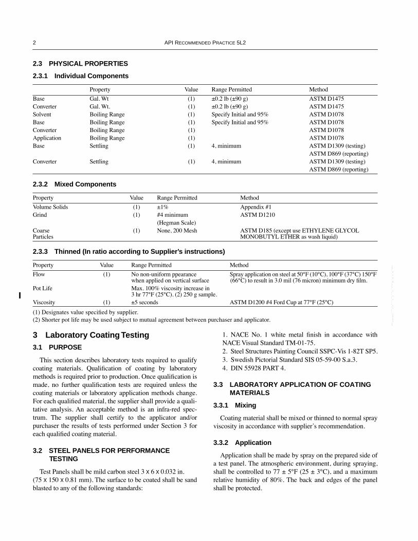
3.1 PURPOSE
This section describes laboratory tests required to qualifycoating materials. QualiÞcation of coating by laboratorymethods is required prior to production. Once qualiÞcation ismade, no further qualiÞcation tests are required unless thecoating materials or laboratory application methods change.For each qualiÞed material, the supplier shall provide a quali-tative analysis. An acceptable method is an infra-red spec-trum. The supplier shall certify to the applicator and/orpurchaser the results of tests performed under Section 3 foreach qualiÞed coating material.
3.2 STEEL PANELS FOR PERFORMANCE TESTING
Test Panels shall be mild carbon steel 3
x
6
x
0.032 in. (75
x
150
x
0.81 mm). The surface to be coated shall be sandblasted to any of the following standards:
1. NACE No. 1 white metal Þnish in accordance withNACE Visual Standard TM-01-75.2. Steel Structures Painting Council SSPC-Vis 1-82T SP5.3. Swedish Pictorial Standard SIS 05-59-00 S.a.3.4. DIN 55928 PART 4.
3.3 LABORATORY APPLICATION OF COATING MATERIALS
3.3.1 Mixing
Coating material shall be mixed or thinned to normal sprayviscosity in accordance with supplierÕs recommendation.
3.3.2 Application
Application shall be made by spray on the prepared side ofa test panel. The atmospheric environment, during spraying,shall be controlled to 77 ± 5¡F (25 ± 3¡C), and a maximumrelative humidity of 80%. The back and edges of the panelshall be protected.
2.3 PHYSICAL PROPERTIES
2.3.1 Individual Components
Property Value Range Permitted Method
Base Gal. Wt (1) ±0.2 lb (±90 g) ASTM D1475Converter Gal. Wt. (1) ±0.2 lb (±90 g) ASTM D1475Solvent Boiling Range (1) Specify Initial and 95% ASTM D1078Base Boiling Range (1) Specify Initial and 95% ASTM D1078Converter Boiling Range (1) ASTM D1078Application Boiling Range (1) ASTM D1078Base Settling (1) 4, minimum ASTM D1309 (testing)
ASTM D869 (reporting)Converter Settling (1) 4, minimum ASTM D1309 (testing)
ASTM D869 (reporting)
2.3.2 Mixed Components
Property Value Range Permitted Method
Volume Solids (1) ±1% Appendix #1Grind (1) #4 minimum ASTM D1210
(Hegman Scale)Coarse Particles
(1) None, 200 Mesh ASTM D185 (except use ETHYLENE GLYCOL MONOBUTYL ETHER as wash liquid)
2.3.3 Thinned (In ratio according to Supplier’s instructions)
Property Value Range Permitted Method
Flow (1) No non-uniform ppearance when applied on vertical surface
Spray application on steel at 50¡F (10¡C), 100¡F (37¡C) 150¡F (66¡C) to result in 3.0 mil (76 micron) minimum dry Þlm.
Pot Life Max. 100% viscosity increase in 3 hr 77¡F (25¡C). (2) 250 g sample.
Viscosity (1) ±5 seconds ASTM D1200 #4 Ford Cup at 77¡F (25¡C)
(1) Designates value speciÞed by supplier.(2) Shorter pot life may be used subject to mutual agreement between purchaser and applicator.
--`,,,,,,,````,`,````,``,```,``-`-`,,`,,`,`,,`---

R
ECOMMENDED
P
RACTICE
FOR
I
NTERNAL
C
OATING
OF
L
INE
P
IPE
FOR
N
ON
-C
ORROSIVE
G
AS
TRANSMISSION
S
ERVICE
3
3.3.3 Dry Film Thickness
Test thickness of Þlm on completed panel (conditioned per3.4) shall be 2.0 ± 0.2 mils (51 ± 5 microns) measured by aÞlm thickness gauge calibrated with a National Bureau ofStandards Coating Thickness Calibration Standard, of athickness within 20% of the speciÞed nominal thickness.
3.4 CONDITIONING OF COATED PANELS
3.4.1
For qualiÞcation tests, the following schedule of con-ditioning shall apply:
Air dry for 10 days at 77 ± 5¡F (25 ± 3¡C), followed by a24 hour bake in a circulating air oven at 120 ± 5¡F (49 ± 3¡C).Relative humidity during the air drying shall not exceed 80%.
3.4.2
After completing the schedule of conditioning out-lined above, panels may be stored at room temperature untilneeded for testing, but not longer than 90 days.
3.5 PERFORMANCE OF LABORATORY COATED STEEL PANELS
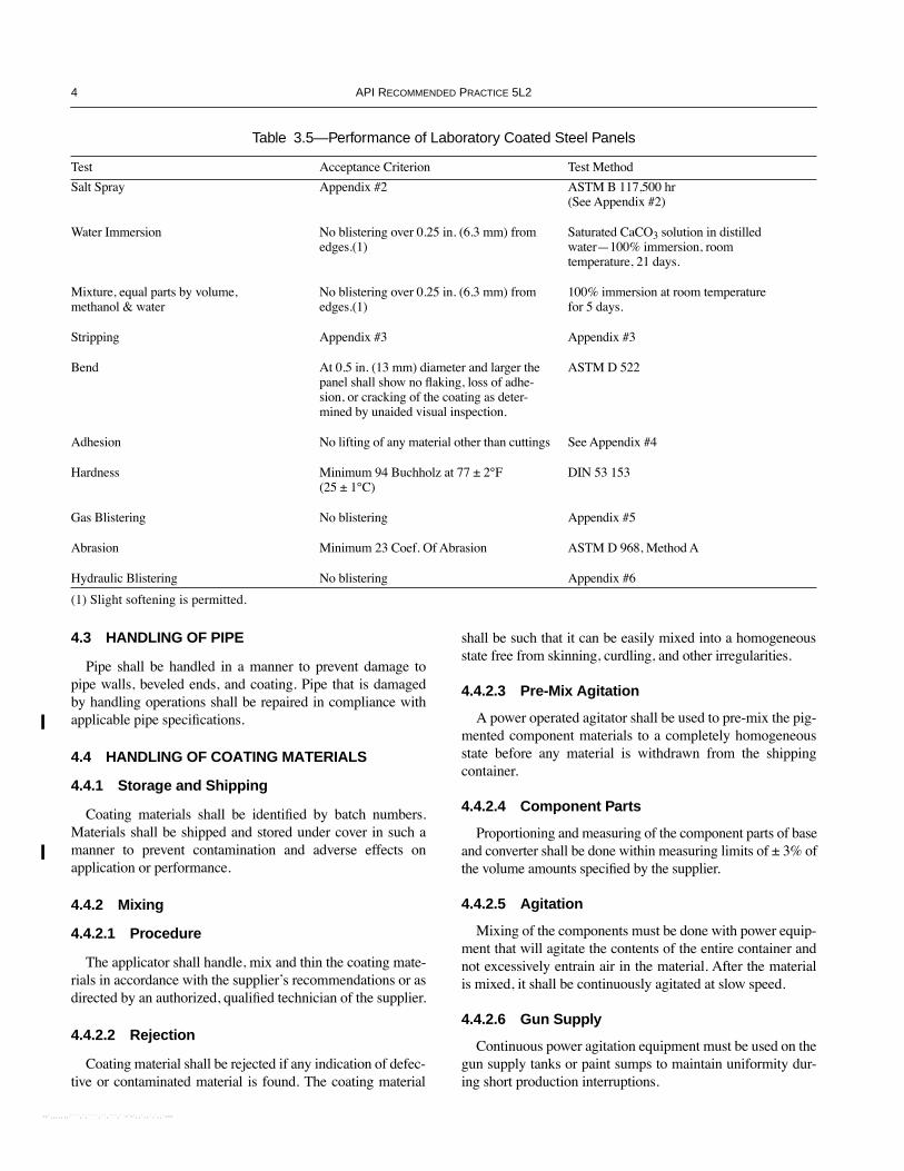
3.5.1 Testing
The tests in Table 3.5 shall be performed on test panelswhich have been prepared, coated, and conditioned in accor-dance with the above procedures. Tests shall be performed onduplicate panels. A test result is acceptable when results fromboth test panels comply with the criteria listed below. In caseof failure of either panel, the test shall be repeated on dupli-cate panels. One such retest shall be permitted.
3.5.2 Additional Tests
At the option of the purchaser or applicator, additional perfor-mance tests may be speciÞed to meet individual requirements.
3.6 PERFORMANCE TESTING—GLASS PANELS
3.6.1 Panel Preparation
3.6.1.1 Panel Size
Test panels shall be standard 1
x
3 in. (25
x
75 mm) glassslides, frosted one side.
3.6.1.2 Cleaning
Panels shall be solvent cleaned by rinsing Þrst in xylol,then in acetone, immediately prior to coating application.
3.6.2 Application of Coating Material
Follow 3.3.1 and 3.3.2, making the coating application onthe frosted side of the panel only. The wet Þlm thickness shallresult in a 2.0 ± 0.2 mil (51 ± 5 micron) dry Þlm.
4 Application Practices
4.1 PURPOSE
This section prescribes equipment and practices used in thesurface preparation of line pipe for internal coating and theapplication of internal coating on the prepared surface.
4.2 GENERAL
4.2.1 Applicator
The applicator is responsible for the quality control pro-duction tests outlined in Section 5 to ensure conformancewith this Recommended Practice.
4.2.2 Plant Access
The Inspector representing the purchaser shall have freeentry at all times while work on the contract of the purchaseris being performed, to all parts of the application site whichconcern surface preparation, coating of the pipe, and qualitycontrol tests.
4.2.3 Material
4.2.3.1 Selection
By agreement between the purchaser and applicator stat alist of coating materials previously qualiÞed by either the pur-chaser or applicator under Coating Material SpeciÞcation,Section 2, shall be prepared. The applicator and/or purchaser,shall then choose the coating material to be applied from thislist. Approval or selection of the materials shall be done farenough in advance (preferably not less than 30 days) to pro-vide material at the scheduled start of the work. Selection ofalternate coating materials from the approved list may bemade at any time by agreement between the purchaser andthe applicator.
4.2.3.2 Batch Samples
It shall be the right of the purchaser or applicator to pro-cure a coating material batch sample prior to or during thecoating application, for the purpose of veriÞcation of con-formance to the coating material speciÞcation.
3.6.3 Performance of Laboratory Coated Glass Panels
TestAcceptance Criterion Test Method
Pinhole (Wet Film) No pinholes Appendix GPinhole (Cured Film) No pinholes Appendix G
--`,,,,,,,````,`,````,``,```,``-`-`,,`,,`,`,,`---
4 API R
ECOMMENDED
P
RACTICE
5L2
4.3 HANDLING OF PIPE
Pipe shall be handled in a manner to prevent damage topipe walls, beveled ends, and coating. Pipe that is damagedby handling operations shall be repaired in compliance withapplicable pipe speciÞcations.
4.4 HANDLING OF COATING MATERIALS
4.4.1 Storage and Shipping
Coating materials shall be identiÞed by batch numbers.Materials shall be shipped and stored under cover in such amanner to prevent contamination and adverse effects onapplication or performance.
4.4.2 Mixing
4.4.2.1 Procedure
The applicator shall handle, mix and thin the coating mate-rials in accordance with the supplierÕs recommendations or asdirected by an authorized, qualiÞed technician of the supplier.
4.4.2.2 Rejection
Coating material shall be rejected if any indication of defec-tive or contaminated material is found. The coating material
shall be such that it can be easily mixed into a homogeneousstate free from skinning, curdling, and other irregularities.
4.4.2.3 Pre-Mix Agitation
A power operated agitator shall be used to pre-mix the pig-mented component materials to a completely homogeneousstate before any material is withdrawn from the shippingcontainer.
4.4.2.4 Component Parts
Proportioning and measuring of the component parts of baseand converter shall be done within measuring limits of ± 3% ofthe volume amounts speciÞed by the supplier.
4.4.2.5 Agitation
Mixing of the components must be done with power equip-ment that will agitate the contents of the entire container andnot excessively entrain air in the material. After the materialis mixed, it shall be continuously agitated at slow speed.
4.4.2.6 Gun Supply
Continuous power agitation equipment must be used on thegun supply tanks or paint sumps to maintain uniformity dur-ing short production interruptions.
Table 3.5—Performance of Laboratory Coated Steel Panels
Test Acceptance Criterion Test Method
Salt Spray Appendix #2 ASTM B 117,500 hr (See Appendix #2)
Water Immersion No blistering over 0.25 in. (6.3 mm) from edges.(1)
Saturated CaCO
3
solution in distilled waterÑ100% immersion, room temperature, 21 days.
Mixture, equal parts by volume, methanol & water
No blistering over 0.25 in. (6.3 mm) from edges.(1)
100% immersion at room temperature for 5 days.
Stripping Appendix #3 Appendix #3
Bend At 0.5 in. (13 mm) diameter and larger the panel shall show no ßaking, loss of adhe-sion, or cracking of the coating as deter-mined by unaided visual inspection.
ASTM D 522
Adhesion No lifting of any material other than cuttings See Appendix #4
Hardness Minimum 94 Buchholz at 77 ± 2¡F (25 ± 1¡C)
DIN 53 153
Gas Blistering No blistering Appendix #5
Abrasion Minimum 23 Coef. Of Abrasion ASTM D 968, Method A
Hydraulic Blistering No blistering Appendix #6
(1) Slight softening is permitted.
--`,,,,,,,````,`,````,``,```,``-`-`,,`,,`,`,,`---
R
ECOMMENDED
P
RACTICE
FOR
I
NTERNAL
C
OATING
OF
L
INE
P
IPE
FOR
N
ON
-C
ORROSIVE
G
AS
TRANSMISSION
S
ERVICE
5
4.4.2.7 Pot Life
Any material which has exceeded its pot life shall berejected.
4.5 CLEANING OF PIPE
4.5.1 General
The cleaning shall be of sufÞcient quality to allow a Þrmcontinuous bond of the cured coating to the pipe, and should beperformed immediately preceding the application of the coat-ing material. Surface conditioning, such as grinding, shall resultin pipe surface Þnish compatible with cleaning requirements.The cleaning method used (wet, brush, or abrasive cleaning) isat the applicatorÕs option, unless the purchaser speciÞes a spe-ciÞc method. If the purchaser speciÞes abrasive cleaning, thedegree of cleaning (e.g., Sa 2
1
/
2
) shall also be speciÞed.
4.5.2 Degree of Cleaning
All loose mill scale and rust, water, oil, graphite, grease,marking materials, and other foreign materials that adverselyaffect the quality of the coating shall be removed from thesurface to be coated.
4.5.3 Wet Cleaning
When wet cleaning is performed with detergents, this pro-cess shall be immediately followed by sufÞcient rinsing withclear water to remove all harmful residue of any cleaningagents or detergents.
4.5.4 Drying
Removal of water may be accelerated by heating, but in nocase shall this heating adversely affect the metallurgical proper-ties of the steel, or deposit surface contaminations. Pipe surfaceshall be thoroughly dry before application of coating material.
4.5.5 Dry Cleaning
4.5.5.1 Method
Dry cleaning methods are brushing or abrasive blasting ofthe pipe. All components of the cleaning machine that enterthe pipe shall be clean to prevent the deposition of grease,dirt, or other foreign material on the cleaned pipe surface.
4.5.5.2 Cleaning Machine Brushes
The cleaning machine brushes should be maintained ateven pressures on all surfaces of the pipe interior to ensureadequate cleaning of the weld and adjacent areas. Burnishingof pipe surfaces should be avoided.
4.5.5.3 Cleaning and Coating
The cleaned surface shall not be allowed to deteriorateprior to the coating application. Cleaning and coating shall bedone in separate stages to permit surface examination andprevent coating contamination.
4.5.6 Use of Air
Clean air may be used to accelerate drying and cleaning.
4.6 COATING OF PIPE
4.6.1 Equipment
4.6.1.1 Air Atomization
Air atomization application is not permitted under thisRecommended Practice, except as permitted in 4.7.3.
4.6.1.2 Filters
Adequate Þlters shall be present in the equipment to ensurethat foreign substances or detrimental particles are not carriedto application assemblies.
4.6.1.3 Pressure Gauges
The coating material line to the spray guns should beequipped with a pressure gauge. For accurate pressure read-ings on airless spray unites, the pressure gauge should beequipped with a pulsation dampener. The location of thisgauge should be downstream of all pressure drop causingdevices, as near to the gun tips as is practicable.
4.6.2 Temperature of Pipe Surface
The temperature of pipe at time of application shall notexceed 150¡F (66¡C), or be less than 50¡F (10¡C).
4.6.3 Thickness of Coating
4.6.3.1 Dry Film Thickness
The minimum dry Þlm thickness of the cured coatingshould be speciÞed by the purchaser at the time the order isplaced. Where no minimum thickness is speciÞed, the mini-mum dry Þlm thickness shall be 1.5 mils (38 microns).
4.6.3.2 Wet Film Thickness
The supplier shall recommend the range of wet Þlm thick-ness that will be necessary to produce the required dry Þlmthickness. This applies to coating material that has beenthinned to proper application viscosity.
4.6.3.3 Pipe Ends
The purchaser should specify an internal cutback distance,if required. Suitable means shall be used to prevent depositing
--`,,,,,,,````,`,````,``,```,``-`-`,,`,,`,`,,`---
6 API R
ECOMMENDED
P
RACTICE
5L2
coating material on bevels and lands. Coating material depos-ited on bevels and lands of the pipe ends or in cutback areasshall be removed immediately after coating.
4.6.4 Protection of Uncured Coating
Coating shall be applied in a covered or enclosed spaceshielded from high winds, blowing dust and dirt and inclem-ent weather. Protection from these conditions shall be pro-vided until the coating is tack free.
4.6.5 Acceleration of Initial Cure
Heat may be used to accelerate cure, providing it producesno adverse effects to the pipe or coating.
4.6.6 Coating Film
4.6.6.1 Unfavorable Operating Conditions
Coating operations must be stopped when conditions asdeÞned by the other provisions of this Recommended Prac-tice indicate that an inferior coating will result.
4.6.6.2 Retention of Coated Pipe
Applicators should have provisions for coated pipe to beretained following coating application for inspection purposes.
4.6.6.3 Relative Humidity
If heat is not used to accelerate cure, coating operationsshould be suspended when the relative humidity is 90% orgreater in the coating area.
4.7 REPAIRS TO COATING
4.7.1 Repair Limitations
Defective or damaged coating shall be repaired by theapplicator. If the total area of repair exceeds 1% of the totalinternal pipe surface, the entire pipe shall be recoated.Smaller areas may be spot repaired per 4.7.3.
4.7.2 Film Thickness
Minimum Þlm thickness of coating applied during repairshall comply with 4.6.3.1.
4.7.3 Repair to Small Areas
Spot repairs may be made with a manual atomizing spraygun or brush.
4.7.4 Runs and Sags
Heavy runs or sags of coating should be smoothed out bysanding or scraping prior to recoating. Coating that overlays
areas which were inadequately cleaned shall be completelyremoved and the surface properly cleaned prior to recoating.Unbonded coating shall be completely removed.
4.7.5 Roughened Surface
Roughened coating should be smoothed and all edges ofbonded material must be Òfeathered outÓ prior to recoating.
4.7.6 Repair and Recoating
Any operation such as coating repair, pipe wall repair, etc.,must not be attempted until sufÞcient cure and hardening ofcoating Þlm has occurred, so that Þlm damage is prevented.Prior to recoating, pipe should be thoroughly cleaned toremove dust and accumulated debris.
4.8 PIPE MARKING
4.8.1 Identification
When identiÞcation stencils and other markings areapplied to the inside pipe wall, application shall be done in amanner that will not damage the internal coating. Stencilingor marking paint must be compatible with the coating on thepipe and of a contrasting color.
4.8.2 Restenciling
If a pipe requires rework which invalidates existing stencilinformation, then that pipe must be restenciled when repairsare completed.
5 Production Inspection and Acceptance
5.1 PURPOSE
This Section deÞnes the limits of acceptance of internallycoated pipe and methods of Þnal testing to assure compliancetherewith.
5.2 GENERAL
5.2.1 Working Area
A safe working area that is suitable for the performance oftheir duties shall be provided by the applicator for the pur-chaserÕs inspectors and representatives.
5.2.2 Applied Coating Film
The applied coating Þlm should be uniform in gloss, thick-ness and color and should be free of irregularities. Blushing,regardless of the degree of color change, shall not be consid-ered detrimental provided the affected area meets the require-ments of 5.3.4.4 Bond (Adhesion) Test and 5.3.4.2 FilmThickness Test.
--`,,,,,,,````,`,````,``,```,``-`-`,,`,,`,`,,`---
RECOMMENDED PRACTICE FOR INTERNAL COATING OF LINE PIPE FOR NON-CORROSIVE GAS TRANSMISSION SERVICE 7
5.2.3 Special Requirement
Any pipe which requires closer inspection shall be setaside upon curing of the coating. Purchaser may require thatthe applicator set aside such pipe as their representative mayrequest for testing, providing that the amount of such pipeshall not exceed two joints for each eight-hour productionperiod on a current basis, or one pipe from each four-hourproduction period.
5.3 PRODUCTION TESTS
The following production tests are recommended forproper quality control of the coated pipe and should be con-ducted at a frequency that will assure control. The pinhole test(5.3.4.1) and the Þlm thickness test (5.3.4.2) shall be con-ducted hourly and whenever production is interrupted, or pro-duction parameters change. All other production tests shall beconducted once per shift.
5.3.1 Test for pH on Bare Surface of Pickled or Wet Cleaned Pipe
Water having an initial pH value of 6.0 to 8.5 as deter-mined with a pH meter, is poured into the pipe at one end andgathered in a cup at the other end. Limits of pH: within 0.5 ofinitial pH value, and between 6.0 to 8.5, immediately prior tocoating application.
This test for pH is not applicable to the bare surface ofmechanically cleaned pipe.
5.3.2 Panel and Slide Preparation
Metal panels shall be prepared in accordance with 3.2 or in amanner simulating pipe surface condition before coating.
5.3.3 Coating and Curing of Panel or Slide
A panel or slide is attached to the inside of a clean pipe.The panel or slide is coated as the pipe is coated. The panel orslide is to remain in the pipe a minimum of Þve minutes.After the panel or slide is removed, the test area on the pipe isspot repaired. After 15 to 30 minutes of air drying, the testpanel or slide is dried for 10 minutes at 150 to 175¡F (66 to79¡C). The slide or panel is baked in an oven at 300 ± 10¡F(149 ± 6¡C) for 30 minutes or as supplier speciÞes.
5.3.4 Evaluation of Test Panels and Slides
5.3.4.1 Pinhole Test
Observe glass slide before and after curing, holding slideover a slot in a container which houses a 100 watt bulb, the bulb
being a distance of between 4 and 5 in. (100 and 130 mm) fromthe coated slide. Evaluation shall be made by purchaserÕs repre-sentative. Pinhole dispersion shall be held to a minimum.
5.3.4.2 Film Thickness Test
Using a micrometer with rachet, measure the uncoatedslide, then coat and measure the cured slide at the samelocation for slide-plus-coating thickness. The difference ofthe two is the coating thickness and shall be at least 0.2 mils(5 microns) greater than the minimum dry Þlm thicknessspeciÞed by the purchaser.
5.3.4.3 Bend Test
Bend a cured panel 180¡ around a conical mandrel. At 0.5in. (13 mm) diameter and larger, the panel shall show no ßak-ing, loss of adhesion or cracking of the coating, as determinedby unaided visual inspection.
5.3.4.4 Bond (Adhesion) Test
See Appendix D.
5.3.4.5 Cure Test
Immerse cured panel or slide in solvent* for a period offour hours. No softening, wrinkling or blistering of the coat-ing Þlm shall be observed after 30 minutes recovery period atroom temperature.
*Same as thinner used for the coating material.
5.3.4.6 Water Test
After a minimum of 4 hours immersion in either freshwater or an aqueous solution, containing (by weight) 1%sodium chloride, 1% sodium sulfate, and 1% sodium carbon-ate, the cured panel shall exhibit no loss of adhesion, soften-ing, wrinkling, or blistering of the coating Þlm.
5.3.4.7 Stripping Test
See Appendix C.
5.3.5 Production Tests on Pipe
Any of the applicable production tests in 5.3.4 may bemade on cured coating for quality control purposes.
--`,,,,,,,````,`,````,``,```,``-`-`,,`,,`,`,,`---

--`,,,,,,,````,`,````,``,```,``-`-`,,`,,`,`,,`---
9
APPENDIX A—METHOD OF DETERMINING VOLUME SOLIDS
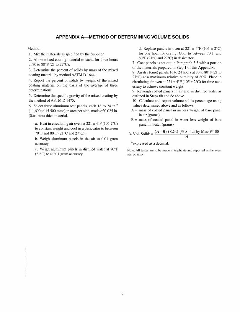
Method:
1. Mix the materials as speciÞed by the Supplier.
2. Allow mixed coating material to stand for three hoursat 70 to 80¡F (21 to 27¡C).
3. Determine the percent of solids by mass of the mixedcoating material by method ASTM D 1644.
4. Report the percent of solids by weight of the mixedcoating material on the basis of the average of threedeterminations.
5. Determine the speciÞc gravity of the mixed coating bythe method of ASTM D 1475.
6. Select three aluminum test panels, each 18 to 24 in.2
(11,600 to 15,500 mm2) in area per side, made of 0.025 in.(0.64 mm) thick material.
a. Heat in circulating air oven at 221 ± 4¡F (105 2¡C)to constant weight and cool in a desiccator to between70¡F and 80¡F (21¡C and 27¡C).
b. Weigh aluminum panels in the air to 0.01 gramaccuracy.
c. Weigh aluminum panels in distilled water at 70¡F(21¡C) to a 0.01 gram accuracy.
d. Replace panels in oven at 221 ± 4¡F (105 ± 2¡C)for one hour for drying. Cool to between 70¡F and80¡F (21¡C and 27¡C) in desiccator.
7. Coat panels as set out in Paragraph 3.3 with a portionof the materials prepared in Step 1 of this Appendix.8. Air dry (cure) panels 16 to 24 hours at 70 to 80¡F (21 to27¡C) at a maximum relative humidity of 80%. Place incirculating air oven at 221 ± 4¡F (105 ± 2¡C) for time nec-essary to achieve constant weight.9. Reweigh coated panels in air and in distilled water asoutlined in Steps 6b and 6c above.10. Calculate and report volume solids percentage usingvalues determined above and as follows:
A = mass of coated panel in air less weight of bare panelin air (grams)
B = mass of coated panel in water less weight of barepanel in water (grams)
*expressed as a decimal.
Note: All testes are to be made in triplicate and reported as the aver-age of same.
% Vol. SolidsA BÐ( ) S.G.( ) % Solids by Mass( )*100
A--------------------------------------------------------------------------------------------------=
--`,,,,,,,````,`,````,``,```,``-`-`,,`,,`,`,,`---

--`,,,,,,,````,`,````,``,```,``-`-`,,`,,`,`,,`---
11
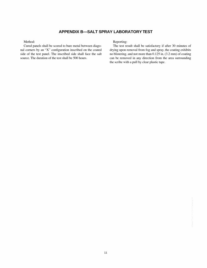
APPENDIX B—SALT SPRAY LABORATORY TEST
Method:Cured panels shall be scored to bare metal between diago-
nal corners by an ÒXÓ conÞguration inscribed on the coatedside of the test panel. The inscribed side shall face the saltsource. The duration of the test shall be 500 hours.
Reporting:The test result shall be satisfactory if after 30 minutes of
drying upon removal from fog and spray, the coating exhibitsno blistering, and not more than 0.125 in. (3.2 mm) of coatingcan be removed in any direction from the area surroundingthe scribe with a pull by clear plastic tape.
--`,,,,,,,````,`,````,``,```,``-`-`,,`,,`,`,,`---

--`,,,,,,,````,`,````,``,```,``-`-`,,`,,`,`,,`---
13
APPENDIX C—STRIPPING TEST
The panel shall be placed on a ßat surface with the coatedside up. A sharp blade, held at approximately 60¡ to the sur-face should be pushed so that the blade has a tendency to liftthe coating. The coating shall not be removed from the test
panel in strips but shall ßake off. The ßakes when rolledbetween the thumb and foreÞnger shall produce powderyparticles.
--`,,,,,,,````,`,````,``,```,``-`-`,,`,,`,`,,`---

--`,,,,,,,````,`,````,``,```,``-`-`,,`,,`,`,,`---

15
APPENDIX D—ADHESION LABORATORY TEST
In an area of the panel at least 1/2 in. (13 mm) removedfrom an edge, using a new stiff razor blade, cut the coatingthrough to the metal with 16 lines evenly spaced over oneinch. Then make 16 similar cuts at 90¡ through the previ-ously made 16 cuts.
The cuttings will thus produce 225 squares of coatingattached to the metal, each about 1/16 in. (1.6 mm) on a side.
Apply 1 in. (25 mm) wide clear plastic tape to the area.Firmly press with the thumb nail so as to yield a uniformcolor of contact area. Remove the tape with a snappingaction.
Inspect the squares thus produced. Acceptance is consti-tuted by lifting of no material other than cuttings.
--`,,,,,,,````,`,````,``,```,``-`-`,,`,,`,`,,`---

--`,,,,,,,````,`,````,``,```,``-`-`,,`,,`,`,,`---
17
APPENDIX E—GAS BLISTERING LABORATORY TEST
The panel shall be placed in suitable pressure equipment.Using dry nitrogen gas, build the pressure within the equip-ment to 1200 psi ± 100 psi (8.3 ± 0.7 MPs). Continue test asfollows:
1. The temperature shall be adjusted to 77¡F ± 10¡F (25 ± 6¡C).
2. The pressure shall be maintained during 24 hours andthen released during a period of not more than Þveseconds.3. The coating shall be examined within three minutesfrom the release of pressure. Any blister found shall con-stitute a failure.
--`,,,,,,,````,`,````,``,```,``-`-`,,`,,`,`,,`---

--`,,,,,,,````,`,````,``,```,``-`-`,,`,,`,`,,`---
19
APPENDIX F—HYDRAULIC BLISTERING LABORATORY TEST
The panel shall be placed in suitable hydraulic pressurizingequipment. Using distilled water saturated with calcium car-bonate, increase the hydraulic pressure to 2400 ± 500 psi(16.5 ± 3.4 MPs). Continue as follows:
1. Maintain 77 ± 5¡F (25 ± 3¡C) in the pressure equipment.2. Maintain test pressure for 24 hours.3. Quickly release pressure.4. Observe panel within 5 minutes. Any blister foundshall constitute a failure.
--`,,,,,,,````,`,````,``,```,``-`-`,,`,,`,`,,`---

--`,,,,,,,````,`,````,``,```,``-`-`,,`,,`,`,,`---
21
APPENDIX G—PINHOLE LABORATORY TEST
The coating application shall be made on prepared glasspanels as described in 3.3. Examination of panels shall bemade as follows:
a. Wet FilmÑFive minutes after application of the coatingmaterial, an examination for pinholes in the Þlm shall be madeby momentarily holding the panel to a strong light source, 5 in.(130 mm) from an illuminated 100-watt bulb. An opaqueshield to prevent light interference to observation of the panelbeing viewed shall support the panel over a viewing slot. The
opaque shield shall extend a minimum of 6 in. (150 mm)around all sides of the panel. Any pinhole shall constitute afailure.b. Cured FilmÑIf the coating is acceptable in the wet stateabove, it shall be held an additional 15 to 30 minutes for aircuring and then placed in a circulating warm air oven at 150to 175¡F (66 to 79¡C) for a minimum 30 minutes. Observa-tion at the light source described above shall be repeated. Anypinhole shall constitute a failure.
--`,,,,,,,````,`,````,``,```,``-`-`,,`,,`,`,,`---

--`,,,,,,,````,`,````,``,```,``-`-`,,`,,`,`,,`---

07/02
--`,,,,,,,````,`,````,``,```,``-`-`,,`,,`,`,,`---

Additional copies are available through Global EngineeringDocuments at (800) 854-7179 or (303) 397-7956
Information about API Publications, Programs and Services isavailable on the World Wide Web at: http://www.api.org
Product No. G5L204
--`,,,,,,,````,`,````,``,```,``-`-`,,`,,`,`,,`---


