
Recommended Plumbing Configurations for … Plumbing Configurations for Reduction in...
6
Recommended Plumbing Configurations for Reduction in Per/Polyfluoroalkyl Substance Background with Agilent 1260/1290 Infinity (II) LC Systems Application Note Authors Tarun Anumol Agilent Technologies Inc. 2850 Centerville Rd, Wilmington, DE, USA Sheher Bano Mohsin, and Michael Woodman Agilent Technologies Inc. Wooddale, IL, USA Peter Abrahamsson Agilent Technologies Ltd. Sweden Environmental Introduction Per/Polyfluoroalkyl substances (PFASs), also known as perfluorinated compounds (PFCs), are substances that have a few or all of the hydrogen atoms in an alkyl chain replaced by fluorine. These C-F bonds give them uniquely desirable properties for use in industry and commerce. However, PFASs are persistent and bioaccumulative in the environment and wildlife, making them contaminants of concern. Their wide ranging use leads to emission into the environment. PFASs such as perfluorooctanoic acid (PFOA) and perfluorooctane sulfanoic acid (PFOS) are ubiquitous, and have been detected in water, soil, sludge, and biota in the parts per billion (ppb) or parts per trillion (ppt) range. As a result, The USEPA has recently issued a combined drinking water health advisory for PFOA and PFOS at 70 ng/L. Several states in the US have drinking water advisories that range from 20–400 ng/L for some of these PFASs. Since PFASs are routinely used in manufacturing processes, it is possible to have system contamination that may be caused by solvents, tubing, fittings, filters, and other parts used in the manufacture and routine operation of a liquid chromatograph. Polytetrafluoroethylene (PTFE) is a fluoropolymer used in all major (U)HPLC systems, and can be a potential source of PFAS contamination during analysis. This application note describes the various potential sources of PFAS contamination in an Agilent 1260 Infinity II and an Agilent 1290 Infinity II system, while providing a solution to significantly reduce PFAS background interference to allow sensitive quantification of these analytes with Agilent LC/MS systems. This application note is intended for users with dedicated LC systems to perform ultra-low trace level analysis of PFASs with minimal background. For users performing multiple analyses on the same LC, the use of a delay column is suggested to reduce PFAS background.
Transcript of Recommended Plumbing Configurations for … Plumbing Configurations for Reduction in...
Recommended Plumbing Configurations for Reduction in Per/Polyfluoroalkyl Substance Background with Agilent 1260/1290 Infinity (II) LC Systems
Application Note
Authors
Tarun Anumol Agilent Technologies Inc. 2850 Centerville Rd, Wilmington, DE, USA
Sheher Bano Mohsin, and Michael Woodman Agilent Technologies Inc. Wooddale, IL, USA
Peter Abrahamsson Agilent Technologies Ltd. Sweden
Environmental
IntroductionPer/Polyfluoroalkyl substances (PFASs), also known as perfluorinated compounds (PFCs), are substances that have a few or all of the hydrogen atoms in an alkyl chain replaced by fluorine. These C-F bonds give them uniquely desirable properties for use in industry and commerce. However, PFASs are persistent and bioaccumulative in the environment and wildlife, making them contaminants of concern. Their wide ranging use leads to emission into the environment. PFASs such as perfluorooctanoic acid (PFOA) and perfluorooctane sulfanoic acid (PFOS) are ubiquitous, and have been detected in water, soil, sludge, and biota in the parts per billion (ppb) or parts per trillion (ppt) range. As a result, The USEPA has recently issued a combined drinking water health advisory for PFOA and PFOS at 70 ng/L. Several states in the US have drinking water advisories that range from 20–400 ng/L for some of these PFASs.
Since PFASs are routinely used in manufacturing processes, it is possible to have system contamination that may be caused by solvents, tubing, fittings, filters, and other parts used in the manufacture and routine operation of a liquid chromatograph. Polytetrafluoroethylene (PTFE) is a fluoropolymer used in all major (U)HPLC systems, and can be a potential source of PFAS contamination during analysis. This application note describes the various potential sources of PFAS contamination in an Agilent 1260 Infinity II and an Agilent 1290 Infinity II system, while providing a solution to significantly reduce PFAS background interference to allow sensitive quantification of these analytes with Agilent LC/MS systems. This application note is intended for users with dedicated LC systems to perform ultra-low trace level analysis of PFASs with minimal background. For users performing multiple analyses on the same LC, the use of a delay column is suggested to reduce PFAS background.
2
Results and Discussion
Solvent line modifications1. Replace the solvent bottle caps with polypropylene (PP)
GL45 caps (VWR, p/n 89059-796)
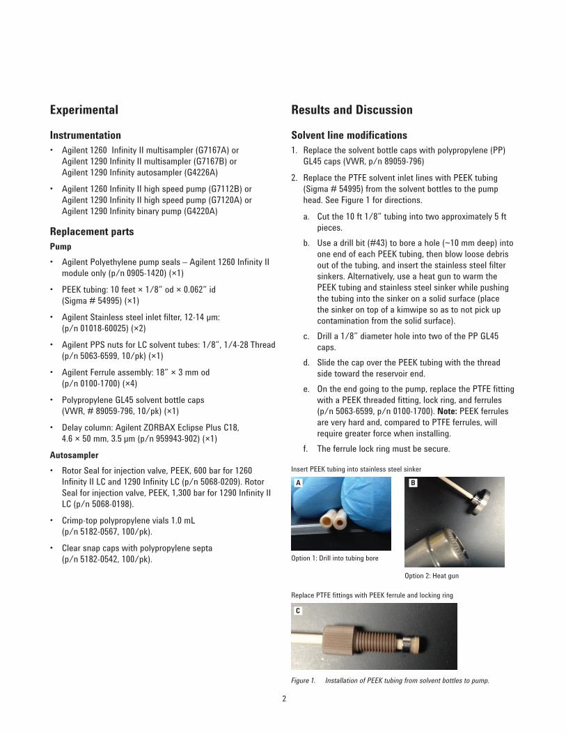
2. Replace the PTFE solvent inlet lines with PEEK tubing (Sigma # 54995) from the solvent bottles to the pump head. See Figure 1 for directions.
a. Cut the 10 ft 1/8” tubing into two approximately 5 ft pieces.
b. Use a drill bit (#43) to bore a hole (~10 mm deep) into one end of each PEEK tubing, then blow loose debris out of the tubing, and insert the stainless steel filter sinkers. Alternatively, use a heat gun to warm the PEEK tubing and stainless steel sinker while pushing the tubing into the sinker on a solid surface (place the sinker on top of a kimwipe so as to not pick up contamination from the solid surface).
c. Drill a 1/8” diameter hole into two of the PP GL45 caps.
d. Slide the cap over the PEEK tubing with the thread side toward the reservoir end.
e. On the end going to the pump, replace the PTFE fitting with a PEEK threaded fitting, lock ring, and ferrules (p/n 5063-6599, p/n 0100-1700). Note: PEEK ferrules are very hard and, compared to PTFE ferrules, will require greater force when installing.
f. The ferrule lock ring must be secure.
Experimental
Instrumentation• Agilent 1260 Infinity II multisampler (G7167A) or
Agilent 1290 Infinity II multisampler (G7167B) or Agilent 1290 Infinity autosampler (G4226A)
• Agilent 1260 Infinity II high speed pump (G7112B) or Agilent 1290 Infinity II high speed pump (G7120A) or Agilent 1290 Infinity binary pump (G4220A)
Replacement partsPump• Agilent Polyethylene pump seals – Agilent 1260 Infinity II
module only (p/n 0905-1420) (×1)
• PEEK tubing: 10 feet × 1/8” od × 0.062” id (Sigma # 54995) (×1)
• Agilent Stainless steel inlet filter, 12-14 µm: (p/n 01018-60025) (×2)
• Agilent PPS nuts for LC solvent tubes: 1/8”, 1/4-28 Thread (p/n 5063-6599, 10/pk) (×1)
• Agilent Ferrule assembly: 18” × 3 mm od (p/n 0100-1700) (×4)
• Polypropylene GL45 solvent bottle caps (VWR, # 89059-796, 10/pk) (×1)
• Delay column: Agilent ZORBAX Eclipse Plus C18, 4.6 × 50 mm, 3.5 µm (p/n 959943-902) (×1)
Autosampler• Rotor Seal for injection valve, PEEK, 600 bar for 1260
Infinity II LC and 1290 Infinity LC (p/n 5068-0209). Rotor Seal for injection valve, PEEK, 1,300 bar for 1290 Infinity II LC (p/n 5068-0198).
• Crimp-top polypropylene vials 1.0 mL (p/n 5182-0567, 100/pk).
• Clear snap caps with polypropylene septa (p/n 5182-0542, 100/pk).
Figure 1. Installation of PEEK tubing from solvent bottles to pump.
Insert PEEK tubing into stainless steel sinker
Option 1: Drill into tubing bore
Option 2: Heat gun
Replace PTFE fittings with PEEK ferrule and locking ring
A B
C
3
• Note: PFASs can stick onto the needle and needle seat after high concentration injections. Make sure to use the multiwash program with at least 15–20 second wash cycles of the needle and needle seat in the method. To check for PFAS contamination in the needle or seat, perform an injection in bypass mode and if contamination disappears, replace the needle and needle seat.
3. Replace the glass reservoir inlet filter (p/n 01018-60025) with a stainless steel reservoir inlet filter in both solvent lines.
4. Drain and remove the existing solvent lines, and install newly prepared PEEK lines.
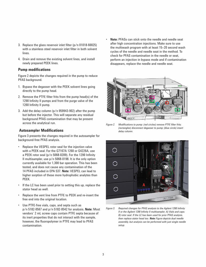
Pump modificationsFigure 2 depicts the changes required in the pump to reduce PFAS background.
1. Bypass the degasser with the PEEK solvent lines going directly to the pump head.
2. Remove the PTFE filter frits from the pump head(s) of the 1290 Infinity II pumps and from the purge valve of the 1260 Infinity II pump.
3. Add the delay column (p/n 959943-902) after the pump but before the injector. This will separate any residual background PFAS contamination that may be present across the analytical run.
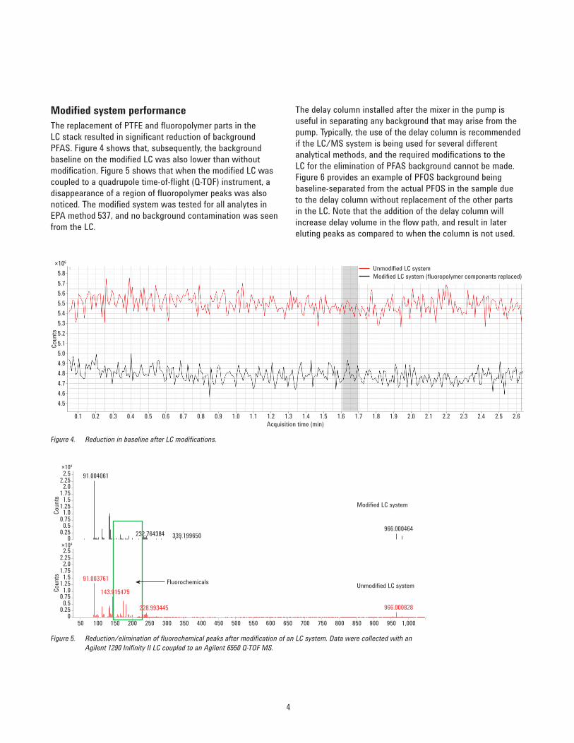
Autosampler ModificationsFigure 3 presents the changes required in the autosampler for background-free PFAS analysis.
• Replace the VESPEL rotor seal for the injection valve with a PEEK seal. For the G7167A 1260 or G4226A, use a PEEK rotor seal (p/n 5068-0209). For the 1290 Infinity II multisampler, use p/n 5068-0198. It is the only option currently available for 1,300 bar operation. This has been tested, and does not cause any contamination of the 14 PFAS included in EPA 537. Note: VESPEL can lead to higher sorption of these more hydrophobic analytes than PEEK.
• If the LC has been used prior to setting this up, replace the stator head as well.
• Replace the vent line from PTFE to PEEK and re-insert the free end into the original location.
• Use PTFE-free vials, caps, and septa such as p/n 5182-0567 and p/n 5182-0542 for analysis. Note: Most vendors’ 2 mL screw caps contain PTFE septa because of its inert properties that do not interact with the sample, however, the fluoropolymer in PTFE may lead to PFAS contamination.
Figure 2. Modifications to pump: (red circles) remove PTFE filter frits; (rectangles) disconnect degasser to pump; (blue circle) insert delay column.
Figure 3. Required changes for PFAS analysis to the Agilent 1260 Infinity II or the Agilent 1290 Infinity II multisampler. A) Vials and caps; B) rotor seal. If the LC has been used for prior PFAS analysis, then replace stator head too. Note: Figure depicts dual needle assembly, but analysis can be performed with just single needle setup.
A
B
4
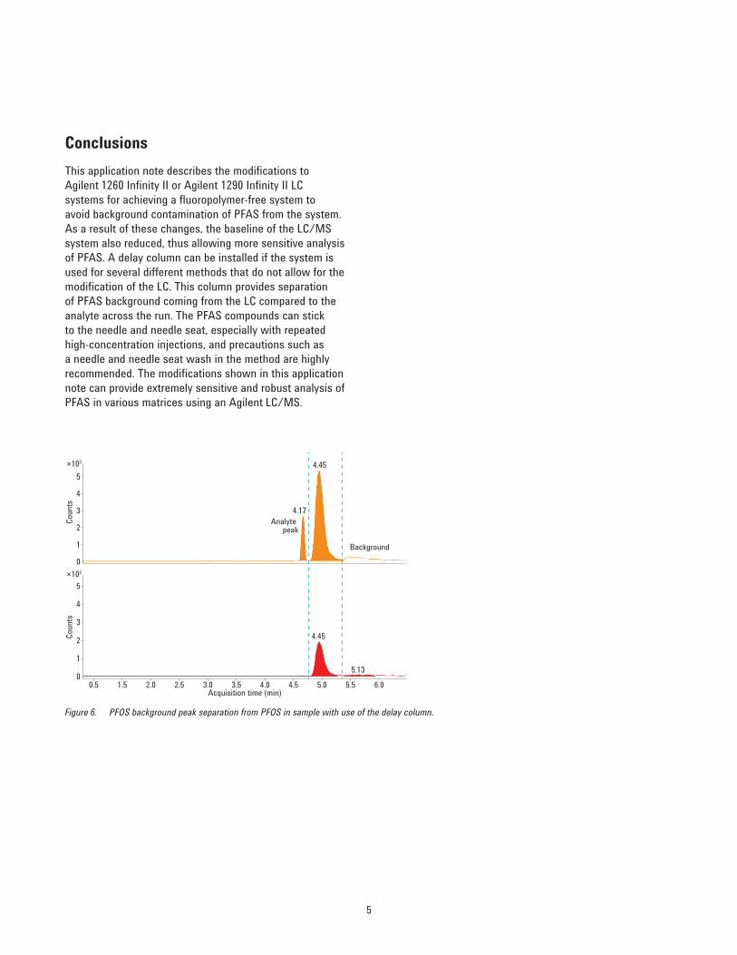
The delay column installed after the mixer in the pump is useful in separating any background that may arise from the pump. Typically, the use of the delay column is recommended if the LC/MS system is being used for several different analytical methods, and the required modifications to the LC for the elimination of PFAS background cannot be made. Figure 6 provides an example of PFOS background being baseline-separated from the actual PFOS in the sample due to the delay column without replacement of the other parts in the LC. Note that the addition of the delay column will increase delay volume in the flow path, and result in later eluting peaks as compared to when the column is not used.
Modified system performanceThe replacement of PTFE and fluoropolymer parts in the LC stack resulted in significant reduction of background PFAS. Figure 4 shows that, subsequently, the background baseline on the modified LC was also lower than without modification. Figure 5 shows that when the modified LC was coupled to a quadrupole time-of-flight (Q-TOF) instrument, a disappearance of a region of fluoropolymer peaks was also noticed. The modified system was tested for all analytes in EPA method 537, and no background contamination was seen from the LC.
0.1 0.2 0.3 0.4 0.5 0.6 0.7 0.8 0.9 1.0 1.1 1.2 1.3 1.4 1.5 1.6 1.7 1.8 1.9 2.0 2.1 2.2 2.3 2.4 2.5 2.6
4.54.64.74.84.95.05.15.25.35.45.55.65.75.8
×106
Acquisition time (min)
Coun
ts
Unmodified LC systemModified LC system (fluoropolymer components replaced)
Figure 4. Reduction in baseline after LC modifications.
Figure 5. Reduction/elimination of fluorochemical peaks after modification of an LC system. Data were collected with an Agilent 1290 Inifinity II LC coupled to an Agilent 6550 Q-TOF MS.
×104
×104
Coun
tsCo
unts
00.250.5
0.751.0
1.251.5
1.752.0
2.252.5 91.004061
966.000464232.764384 339.199650
00.250.5
0.751.0
1.251.5
1.752.0
2.252.5
91.003761
966.000828
50 100 150 200 250 300 350 400 450 500 550 600 650 700 750 800 850 900 950 1,000
Modified LC system
Unmodified LC system Fluorochemicals
228.993445
143.915475
5
Figure 6. PFOS background peak separation from PFOS in sample with use of the delay column.
0.5 1.5 2.0 2.5 3.0 3.5 4.0 4.5
4.45
4.17Analyte
peak
Background
4.45
5.13
5.0 5.5 6.00
1
2
3
4
5×10³
Acquisition time (min)
Coun
ts
0
1
2
3
4
5×10³
Coun
ts
ConclusionsThis application note describes the modifications to Agilent 1260 Infinity II or Agilent 1290 Infinity II LC systems for achieving a fluoropolymer-free system to avoid background contamination of PFAS from the system. As a result of these changes, the baseline of the LC/MS system also reduced, thus allowing more sensitive analysis of PFAS. A delay column can be installed if the system is used for several different methods that do not allow for the modification of the LC. This column provides separation of PFAS background coming from the LC compared to the analyte across the run. The PFAS compounds can stick to the needle and needle seat, especially with repeated high-concentration injections, and precautions such as a needle and needle seat wash in the method are highly recommended. The modifications shown in this application note can provide extremely sensitive and robust analysis of PFAS in various matrices using an Agilent LC/MS.
www.agilent.com/chemFor Research Use Only. Not for use in diagnostic procedures.
Agilent shall not be liable for errors contained herein or for incidental or consequential damages in connection with the furnishing, performance, or use of this material.
Information, descriptions, and specifications in this publication are subject to change without notice.
© Agilent Technologies, Inc., 2017 Printed in the USA May 22, 2017 5991-7863EN
For More InformationThese data represent typical results. For more information on our products and services, visit our Web site at www.agilent.com/chem.


