
Reciprocating Compressor M Series Operation Manual...
141
2200B2JE-DA-M-N_2009.02. First edition: 2009/02/02 3 14 15 Botan Koto-ku, Tokyo 135-8482, Japan Reciprocating Compressor M Series Operation Manual 4M/6M/8M CAUTION Before operating, inspecting, or servicing the compressor, read this manual thoroughly to fully understand the contents. Keep this operation manual in a safe, designated place for future reference whenever the manual is needed.
Transcript of Reciprocating Compressor M Series Operation Manual...
2200B2JE-DA-M-N_2009.02. First edition: 2009/02/02
3 14 15 Botan Koto-ku, Tokyo 135-8482, Japan
Reciprocating Compressor M Series Operation Manual 4M/6M/8M
CAUTION Before operating, inspecting, or servicing the compressor, read this manual thoroughly to fully understand the contents.
Keep this operation manual in a safe, designated place for future reference whenever the manual is needed.
Reciprocating Compressor M Series
i
Preface Thank you for having purchased our M series reciprocating compressor (hereinafter indicated as "this
machine").
This operation manual (hereinafter indicated as "this manual") describes safety information, and operational
and maintenance procedures in detail for safe and effective use of this machine.
Before installing or using this machine, make sure to read this manual.
Keep this manual in a safe place near the machine for quick reference.
Caution: Descriptions in this manual and specification of this machine is subject to change without notice.
Reciprocating Compressor M Series
ii
Warranty and Disclaimer
Warranty Clauses If malfunctions occur related to design or manufacture of the product under a normal limitation of use
condition following documents such as operation manual of this product, and if it is within the warranty
period, we will repair or replace the product.
The warranty period is "12 months from factory shipment of this product". If there is an article of agreement,
the description written on the agreement takes precedence in principle.
Disclaimer Clauses (Exclusion of Warranty Clauses) Please note that we assume no product liability for the following disclaimer clauses for this product.
Malfunction or damage which has been caused by accidental forces such as natural disasters
(windstorm, intense rainfall, flood, tidal wave, earthquake, land sinkage, thunderbolt, fire disaster, etc.)
Malfunction, damage, or defect of this product which has been subjected to abnormal use, improper use
(such as keeping this product outside the building or in locations subject to high temperatures and high
humidity, excessive liquid back operation, and repeating start-up/stoppage of the product excessively.)
Malfunction or damage which has been caused by devices or equipment that is not delivered by us or by
operation control method of those devices.
Malfunction or damage which has been caused by using refrigerant (or gases) that are not approved for
this product.
Malfunction or damage which has been caused by performing maintenance and inspection that is not
recommended by us.
Malfunction or damage which has been caused by using parts other than MAYEKAWA genuine parts.
Malfunction or damage which has been caused by redesigning this product that has not instructed by
Mayekawa/Mycom.
Production warranty or any other related warranty of this product.
For complete warranty, terms and condition details contact local Mayekawa/Mycom sales office
Reciprocating Compressor M Series
iii
Important Information
Intended Use of Machine The M series compressor is a reciprocating compressor for refrigerating, cold storage, and air conditioning
systems on which NH3 is used as the primary refrigerant. For the specification of this machine, refer to "2.2
Specification of Compressor".
When performing maintenance described we ask that you use qualified refrigeration personal.
Important Information for Safe Use of Machine MAYEKAWA cannot anticipate all possible hazards including any potential hazards caused by human errors,
and hazards due to the environmental conditions where the machine is used.
There are plenty of guidelines that must be observed for operating the machine the warnings in this manual
and safety labels on the machine are, not all inclusive. When operating this machine, use extreme caution on
required personal safety as well as on the items described in this manual.
Listed below are the important rules for safety work with the machine that apply to all workers including
managers and supervisors.
Before using this machine, carefully read and fully understand the contents written in this manual and reliably
follow the safety procedures.
Operation, maintenance, and inspection of this machine should only be performed by qualified personal
educated about the fundamentals of the machine and trained about the hazards involved and the
measures to avoid danger.
Observe all related federal/national and local codes and regulations.
This machine may be modified without any prior notice. Therefore, the appearance of actual machine
may slightly differ from the descriptions in this manual. If you have any questions contact your sales
offices or service centers.
To prevent an accident, do not attempt to carry out any operation or maintenance other than those
described in this manual, or use the machine for any unapproved purpose.
Replace the parts with the genuine parts.
Every worker including managers and supervisors should actively participate in activities to insure
health and safety in the workplace.
Observe the following precautions when performing maintenance work on electrical control.
Electrical maintenance of the machine must be performed by certified/qualified personal and only those
educated about the electrical control of the machine.
Before servicing or inspecting the electrical equipment or devices, turn "OFF" the motor main power
and control power, and perform lockout/tagout to prevent them from being turned on during the work.
Even when the motor main power and control power are turned "OFF", the machine may be alive if the power
is supplied from outside of the refrigeration system, cold storage, and air conditioning systems. In such cases,
be sure to shut off the power supply on the power source side, and perform lockout/tagout to prevent the
machine from being turned on during the work.
Reciprocating Compressor M Series
iv
About This Manual This manual is English. If any other language is required it is the responsibility to prepare a
manual for safety education and operation instructions.
This manual is copy written. The drawings and technical references including this manual shall not, in
whole or part, be copied, photocopied, or reproduced to any electronic medium or machine readable
form without any prior permission from MAYEKAWA.
The photos or drawings included in this manual may slightly differ from the appearance of actual
machine.
If this manual is lost or damaged, immediately place a purchase order to your local sales offices or
service centers for a new manual. Using the machine without the manual may result in safety issues.
If you resell the machine, never fail to attach this manual to the machine.
Construction of This Manual
Title of section and chapter Description details
Preface Describes the outline of this manual and how to read this manual.
Warranty and Disclaimer Describes clauses and coverage of warranty.
Exclusion of warranty clauses is described as disclaimer.
Important Information Describes important information related to the machine and this manual.
1. Safety
Describes safety information for the worker, safety rules for this machine,
and management details regarding the work safety that is required for
handling the machine.
2. Configuration and
Specification of Compressor
Describes the main components of the machine, functional information,
specification, and service limits.
3. Installation Describes the installation procedure of the machine.
4. Operation of the Compressor Describes the precautions for operating the machine.
5. Maintenance Describes sections and period for inspecting, and assembly and disassembly
of this product.
6. Troubleshooting Describes the methods of the machine in case of problem occurring during
operation of the machine.
7. Related Document Describes supplemental documents such as illustrated parts breakdown and
parts list.
How to Order Genuine Parts Confirm the applicable parts in "7.1 Development View and Configuration Table of the Parts" of "Chapter 7,
Related Document". And inform the product name, part number, part name, and required quantity to your
local sales offices or service centers.
Reciprocating Compressor M Series
v
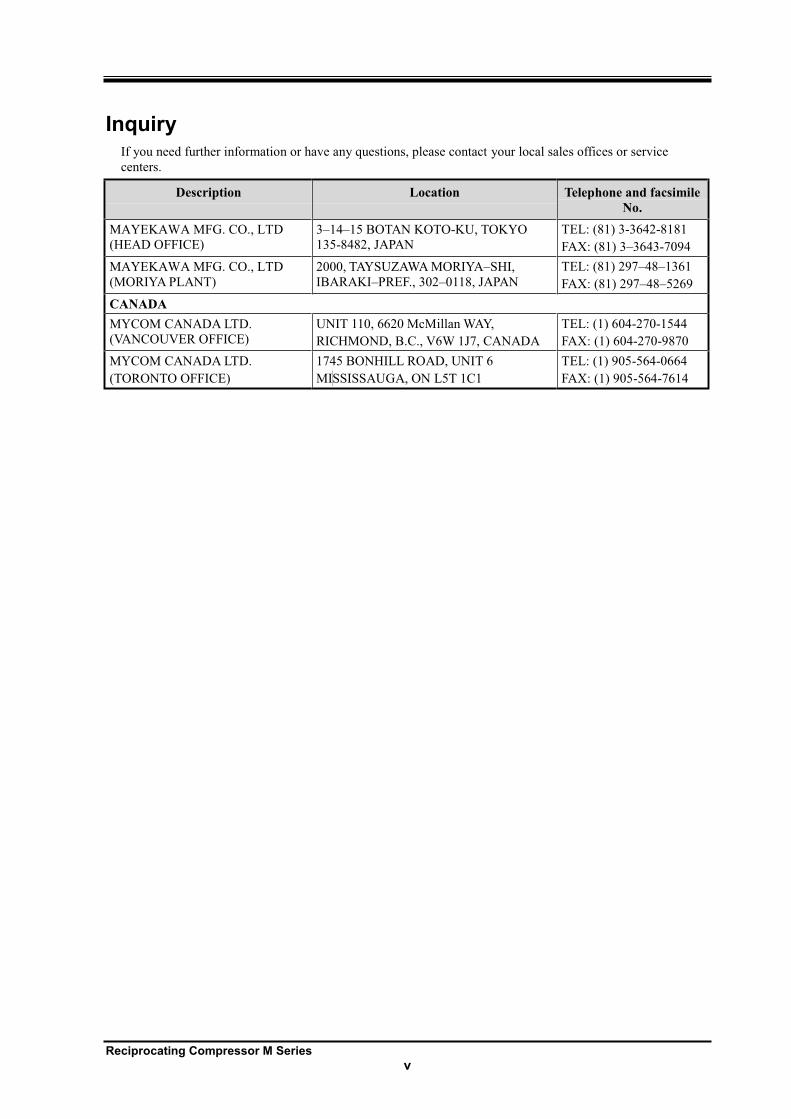
Inquiry If you need further information or have any questions, please contact your local sales offices or service
centers.
Description Location Telephone and facsimile
No.
MAYEKAWA MFG. CO., LTD
(HEAD OFFICE)
3 14 15 BOTAN KOTO-KU, TOKYO
135-8482, JAPAN
TEL: (81) 3-3642-8181
FAX: (81) 3 3643-7094
MAYEKAWA MFG. CO., LTD
(MORIYA PLANT)
2000, TAYSUZAWA MORIYA SHI,
IBARAKI PREF., 302 0118, JAPAN
TEL: (81) 297 48 1361
FAX: (81) 297 48 5269
CANADA
MYCOM CANADA LTD.
(VANCOUVER OFFICE)
UNIT 110, 6620 McMillan WAY,
RICHMOND, B.C., V6W 1J7, CANADA
TEL: (1) 604-270-1544
FAX: (1) 604-270-9870
MYCOM CANADA LTD.
(TORONTO OFFICE)
1745 BONHILL ROAD, UNIT 6
MISSISSAUGA, ON L5T 1C1
TEL: (1) 905-564-0664
FAX: (1) 905-564-7614
Reciprocating Compressor M Series
vi
Revision Description
Operation
manual name
M series
operation
manual
Document
No. 2200B2JE-DA-M-N_2009.02.
First edition
issue date 2009/2/2
Revision
No.
Issuance
Date
Contents of revisions
(modified clause, page, and details) Created/approved by:
Reciprocating Compressor M Series
vii
Table of Contents
1 Safety
1.1 Observation/Prevention ............................................................................. 1-1
1.1.1 Observance (Do's) ................................................................................................. 1-1
1.1.1.1 Do's on Operation ........................................................................................ 1-1
1.1.1.2 Do's on Maintenance ................................................................................... 1-1
1.1.1.3 Do's on Lockout/Tagout after Shutting off the Power .................................. 1-1
1.1.1.4 Do's about Personal Protective Devices ..................................................... 1-1
1.1.1.5 Do's about Handling of Hazardous and Toxic Substances .......................... 1-2
1.1.1.6 Do's about Handling Emergency Situation .................................................. 1-2
1.1.1.7 Do's about Waste Oil, Fluid, and Materials ................................................. 1-2
1.1.1.8 Other Do's .................................................................................................... 1-2
1.1.2 Don'ts ..................................................................................................................... 1-2
1.2 Warnings ..................................................................................................... 1-3
1.2.1 Types and Meanings of Warnings ......................................................................... 1-3
1.2.2 Safety Labels ......................................................................................................... 1-4
1.3 Remaining Hazard ...................................................................................... 1-6
1.4 Safety Devices ............................................................................................ 1-8
1.4.1 Emergency Stop Button ......................................................................................... 1-8
1.4.2 Breakers of Motor Main Power and Control Power (with Lockout/Tagout Mechanisms) ....................................................................... 1-8
1.4.3 Safety Belt/coupling Guard .................................................................................... 1-9
1.4.4 Safety Valve ......................................................................................................... 1-10
1.4.5 Automatic Control and Protection Equipment M compressor .............................. 1-11
1.4.6 Compressor Cooling Fluid Temperature Failure Alarm ....................................... 1-14
1.4.7 Oil Heater and Thermometer Switch ................................................................... 1-14
1.5 Example of Material Safety Data Sheet (MSDS) ..................................... 1-15
2 Configuration and Specification of Compressor
2.1 Configuration of Compressor .................................................................... 2-1
2.1.1 Overall View of Compressor .................................................................................. 2-1
2.1.2 Cross-Sectional View of Assembly ........................................................................ 2-2
2.1.3 Oil Supply Mechanism ........................................................................................... 2-4
2.1.4 Unloader Mechanism ............................................................................................. 2-5
2.2 Specification of Compressor ..................................................................... 2-6
2.2.1 Specification .......................................................................................................... 2-6
2.2.2 Service Limits and Range ...................................................................................... 2-6
2.2.3 External Dimensions .............................................................................................. 2-8
2.3 Selection of V / C-belt ................................................................................. 2-9
Reciprocating Compressor M Series
viii
3 Installation
3.1 Safety Precautions for Installation ............................................................ 3-1
3.2 Installation Works....................................................................................... 3-2
3.2.1 Unpacking .............................................................................................................. 3-2
3.2.2 Storage .................................................................................................................. 3-2
3.2.3 Transfer .................................................................................................................. 3-2
3.2.4 Preparation for Installation ..................................................................................... 3-4
3.2.5 Installation .............................................................................................................. 3-5
3.2.5.1 Installation.................................................................................................... 3-5
3.2.5.2 Position of the Oil Returning Point in the Oil Separator / Procedure of Oil Returning ................................................................................................ 3-5
3.2.5.3 Protection Switch ......................................................................................... 3-5
3.2.5.4 Centering of the Compressor/Driving Machine and Attachment of the V/C-belt .................................................................................................. 3-6
3.2.5.5 Piping ........................................................................................................... 3-9
3.2.5.6 Charging of Refrigeration Oil ......................................................................3-11
3.2.6 Check after Installation ........................................................................................ 3-11
3.3 Documents Related to Installation *1 ...................................................... 3-12
4 Operation of the Compressor
4.1 Refrigerant Oil ............................................................................................ 4-1
4.1.1 Precautions for Selecting the Refrigeration Oil...................................................... 4-1
4.1.2 Initial Charging Method .......................................................................................... 4-2
4.1.3 Replenishment of the Refrigeration Oil .................................................................. 4-2
4.1.4 Set Oil Pressure ..................................................................................................... 4-2
4.1.5 Oil Quantity ............................................................................................................ 4-3
4.2 Initial Operation .......................................................................................... 4-4
4.2.1 Initial Operation Method ......................................................................................... 4-5
4.3 Operation Order of the Unloader ............................................................... 4-6
4.4 Operation Notices....................................................................................... 4-7
4.4.1 Start/Stop Limitation .............................................................................................. 4-7
4.4.2 Action for Stopping the Compressor for Long Period of Time ............................... 4-7
4.4.3 Operation after the Compressor has been stopped for Long Period of Time ....... 4-7
5 Maintenance
5.1 Safety Precautions for Maintenance ......................................................... 5-1
5.2 Periodic Inspection .................................................................................... 5-2
5.2.1 Daily Inspection ..................................................................................................... 5-2
5.2.2 Monthly Inspection ................................................................................................. 5-3
5.2.3 Biannual Inspection ............................................................................................... 5-3
5.3 Maintenance (Overhaul) ............................................................................. 5-4
5.3.1 Maintenance Period and Operation Conditions ..................................................... 5-4
5.3.2 First Inspection ...................................................................................................... 5-5
5.3.3 First Maintenance .................................................................................................. 5-5
Reciprocating Compressor M Series
ix
5.4 Refrigerant Oil Control Standard ............................................................... 5-6
5.5 Disassembly/Assembly .............................................................................. 5-7
5.5.1 Exterior Equipment ................................................................................................ 5-7
5.5.1.1 Removing the Oil Cooler Piping/ Water Cooled Type Oil Cooler ..................................................................... 5-8
5.5.1.2 Removing the Mechanical lock .................................................................... 5-8
5.5.1.3 Removing the Flywheel ............................................................................... 5-8
5.5.1.4 Assembly of the Flywheel ............................................................................ 5-8
5.5.1.5 Assembly of the Mechanical lock ................................................................ 5-9
5.5.1.6 Assembly of the Oil Cooler Piping/ Water Cooled Type Oil Cooler ..................................................................... 5-9
5.5.2 Suction/Discharge Area ....................................................................................... 5-10
5.5.2.1 Removing the Suction/Discharge Shut-off Valve ........................................5-11
5.5.2.2 Assembly of the Suction/Discharge Shut-off Valve ....................................5-11
5.5.2.3 Removing the Discharge Manifolds ............................................................5-11
5.5.2.4 Assembly of the Discharge Manifolds ....................................................... 5-12
5.5.3 Head Cover/Hand Hole Cover ............................................................................. 5-13
5.5.3.1 Removing the Head Jacket Cover ............................................................. 5-14
5.5.3.2 Removing the Head Cover ........................................................................ 5-14
5.5.3.3 Removing the Hand Hole Cover ................................................................ 5-15
5.5.3.4 Assembly of the Hand Hole Cover ............................................................ 5-16
5.5.3.5 Assembly of the Head Cover ..................................................................... 5-16
5.5.3.6 Assembly of the Head Jacket Cover ......................................................... 5-17
5.5.4 Valve Plate/Piston Assembly/Cylinder Sleeve Assembly .................................... 5-18
5.5.4.1 Attachment of the Spacer .......................................................................... 5-19
5.5.4.2 Removing the Valve Plate ......................................................................... 5-19
5.5.4.3 Removing the Piston Assembly ................................................................. 5-19
5.5.4.4 Assembly of the Cylinder Sleeve Assembly .............................................. 5-20
5.5.4.5 Assembly of the Piston Assembly ............................................................. 5-20
5.5.4.6 Assembly of the Suction Plate Valve/Suction Valve Spring ....................... 5-22
5.5.4.7 Assembly of the Valve Plate ...................................................................... 5-22
5.5.4.8 Removal of the Spacer .............................................................................. 5-23
5.5.5 Unloader .............................................................................................................. 5-24
5.5.5.1 Assembly of the Unloader Push Rod Washer ........................................... 5-25
5.5.5.2 Assembly of the Unloader Push Rod Assembly ........................................ 5-25
5.5.5.3 Assembly of the Solenoid Valve Unloader Cover Integrated .................... 5-25
5.5.6 Seal Cover/Mechanical Seal/Oil Seal .................................................................. 5-26
5.5.6.1 Removing the Seal Cover Assembly ......................................................... 5-27
5.5.6.2 Removing the Oil Seal Retainers .............................................................. 5-27
5.5.6.3 Removing the Oil Seal ............................................................................... 5-27
5.5.6.4 Assembly of the Oil Seal ........................................................................... 5-27
5.5.6.5 Assembly of the Mechanical Seal Collar ................................................... 5-28
5.5.6.6 Assembly of the Seal Cover Assembly...................................................... 5-28
5.5.7 Main Bearing Head Assembly/Oil Pump Assembly/Oil Filter Assembly ............. 5-29
5.5.7.1 Removing the Main Bearing Head Assembly ............................................ 5-30
5.5.7.2 Assembly of the Main Bearing Head Gasket............................................. 5-30
5.5.7.3 Assembly of the Main Bearing Head Assembly ........................................ 5-30
Reciprocating Compressor M Series
x
5.5.8 Crankshaft............................................................................................................ 5-31
5.5.8.1 Removing the Crankshaft .......................................................................... 5-32
5.5.8.2 Assembly of the Thrust Roller Bearing (Shaft Side) .................................. 5-33
5.5.8.3 Assembly of the Crankshaft....................................................................... 5-34
5.5.9 Bearing Head ....................................................................................................... 5-35
5.5.9.1 Removing the Bearing Head ..................................................................... 5-36
5.5.9.2 Replacing the Main Bushing (Bearing Head Side) .................................... 5-36
5.5.9.3 Assembly of the Thrust Roller Bearing (Bearing Head Side) .................... 5-36
5.5.9.4 Assembly of the Bearing Head .................................................................. 5-37
5.5.10 Discharge Valve Cage Assembly ........................................................................ 5-38
5.5.10.1 Assembly of the Discharge Valve Spring ................................................... 5-38
5.5.11 Piston Assembly ........................................................................................ 5-39
5.5.11.1 Assembly of the Connecting Rod Bushing ................................................ 5-39
5.5.11.2 Assembly of the Piston Rings .................................................................... 5-40
5.5.12 Cylinder Sleeve Assembly ................................................................................... 5-41
5.5.12.1 Assembly of the Cam Ring ........................................................................ 5-41
5.5.13 Seal Cover Assembly .......................................................................................... 5-42
5.5.13.1 Removing the Shower Flushing Sleeve .................................................... 5-42
5.5.13.2 Assembly of the Mechanical Seal Mating Ring ......................................... 5-43
5.5.13.3 Assembly of the Bellows Oil Sleeve .......................................................... 5-43
5.5.14 Main Bearing Head Assembly ............................................................................. 5-44
5.5.14.1 Replacing the Main Bushing (Pump Side)................................................. 5-44
5.5.14.2 Assembly of the Thrust Washer (Pump Side) ........................................... 5-44
5.5.15 Oil Filter Assembly ............................................................................................... 5-45
6 Troubleshooting
6.1 Troubleshooting Table ............................................................................... 6-1
7 Related Document
7.1 Development View and Configuration Table of the Parts ........................ 7-1
7.2 List of Tightening Torques for Bolts and Nuts ....................................... 7-11
7.3 List of Tools for Disassembly .................................................................. 7-12
7.4 Vibration and Sound Data ........................................................................ 7-14
7.4.1 Vibration ............................................................................................................... 7-14
7.4.2 Sound Data .......................................................................................................... 7-15
7.5 Oil Cooler Heat Rejection (OHR)/Head Jacket Heat Rejection (JHR) (N4M, N6M, N8M) .................. 7-16
7.6 Starting Torque ......................................................................................... 7-25
7.7 Parts Inspection and Replacement Standards ....................................... 7-28
Reciprocating Compressor M Series
1-1
1 Safety
1.1 Observation/Prevention
1.1.1 Observance (Do's)
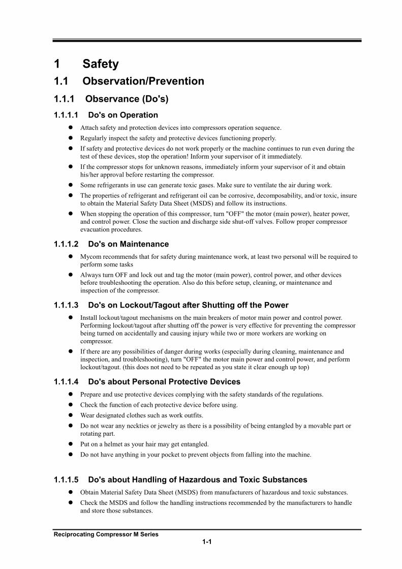
1.1.1.1 Do's on Operation
Attach safety and protection devices into compressors operation sequence.
Regularly inspect the safety and protective devices functioning properly.
If safety and protective devices do not work properly or the machine continues to run even during the
test of these devices, stop the operation! Inform your supervisor of it immediately.
If the compressor stops for unknown reasons, immediately inform your supervisor of it and obtain
his/her approval before restarting the compressor.
Some refrigerants in use can generate toxic gases. Make sure to ventilate the air during work.
The properties of refrigerant and refrigerant oil can be corrosive, decomposability, and/or toxic, insure
to obtain the Material Safety Data Sheet (MSDS) and follow its instructions.
When stopping the operation of this compressor, turn "OFF" the motor (main power), heater power,
and control power. Close the suction and discharge side shut-off valves. Follow proper compressor
evacuation procedures.
1.1.1.2 Do's on Maintenance
Mycom recommends that for safety during maintenance work, at least two personal will be required to
perform some tasks
Always turn OFF and lock out and tag the motor (main power), control power, and other devices
before troubleshooting the operation. Also do this before setup, cleaning, or maintenance and
inspection of the compressor.
1.1.1.3 Do's on Lockout/Tagout after Shutting off the Power
Install lockout/tagout mechanisms on the main breakers of motor main power and control power.
Performing lockout/tagout after shutting off the power is very effective for preventing the compressor
being turned on accidentally and causing injury while two or more workers are working on
compressor.
If there are any possibilities of danger during works (especially during cleaning, maintenance and
inspection, and troubleshooting), turn "OFF" the motor main power and control power, and perform
lockout/tagout. (this does not need to be repeated as you state it clear enough up top)
1.1.1.4 Do's about Personal Protective Devices
Prepare and use protective devices complying with the safety standards of the regulations.
Check the function of each protective device before using.
Wear designated clothes such as work outfits.
Do not wear any neckties or jewelry as there is a possibility of being entangled by a movable part or
rotating part.
Put on a helmet as your hair may get entangled.
Do not have anything in your pocket to prevent objects from falling into the machine.
1.1.1.5 Do's about Handling of Hazardous and Toxic Substances
Obtain Material Safety Data Sheet (MSDS) from manufacturers of hazardous and toxic substances.
Check the MSDS and follow the handling instructions recommended by the manufacturers to handle
and store those substances.
Reciprocating Compressor M Series
1-2
An example of Material Safety Data Sheet (MSDS) is provided as a reference at the end of
this chapter.
1.1.1.6 Do's about Handling Emergency Situation
Formulate an emergency action plan complying with the regulations. Post it in a place where the
workers can always see it.
1.1.1.7 Do's about Waste Oil, Fluid, and Materials
Disposing of refrigerant and oil used for the compressor are subject to a number of regulations for the
environmental protection purposes. Follow the local, state, federal acts and regulations and your
company's rules when disposing of such waste oil, fluid and materials.
1.1.1.8 Other Do's
Keep the floor clean around the refrigerating, cold storage, and air conditioning systems, and keep
passages and walkways clear.
Walk only on the areas set up as a work floor. Also, do not leave tools and cleaning solutions in that
area.
If water or oil is spilled on the compressor or the floor, immediately wipe it off to prevent workers
from injury.
1.1.2 Don'ts Do not remove or relocate any safety device, including electrical interfaces.
Do not disable any safety device by short-circuiting or bypassing without any permission.
Do not leave the compressor unsafe and unattended, by removing a safety cover or some other
measures.
Do not touch, clean, or lubricate any moving part of the compressor during the operation.
Do not touch relays or electric systems such as terminal block with bare hands when turning on the
power.
Reciprocating Compressor M Series
1-3
1.2 Warnings To alert workers to danger, the following two measures are always provided with the compressor.
Warnings described in this manual
Safety labels affixed on the compressor
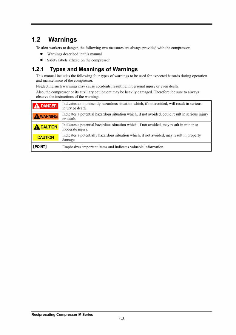
1.2.1 Types and Meanings of Warnings This manual includes the following four types of warnings to be used for expected hazards during operation
and maintenance of the compressor.
Neglecting such warnings may cause accidents, resulting in personal injury or even death.
Also, the compressor or its auxiliary equipment may be heavily damaged. Therefore, be sure to always
observe the instructions of the warnings.
Indicates an imminently hazardous situation which, if not avoided, will result in serious
injury or death.
Indicates a potential hazardous situation which, if not avoided, could result in serious injury
or death.
Indicates a potential hazardous situation which, if not avoided, may result in minor or
moderate injury.
Indicates a potentially hazardous situation which, if not avoided, may result in property
damage.
Emphasizes important items and indicates valuable information.
Reciprocating Compressor M Series
1-4
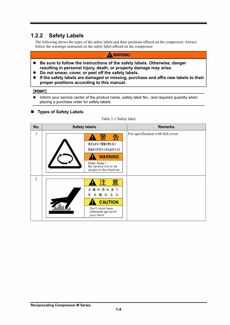
1.2.2 Safety Labels The following shows the types of the safety labels and their positions affixed on the compressor. Always
follow the warnings instructed on the safety label affixed on the compressor.
Be sure to follow the instructions of the safety labels. Otherwise, danger resulting in personal injury, death, or property damage may arise.
Do not smear, cover, or peel off the safety labels. If the safety labels are damaged or missing, purchase and affix new labels to their
proper positions according to this manual.
Inform your service center of the product name, safety label No., and required quantity when placing a purchase order for safety labels.
Types of Safety Labels
Table 1-1 Safety label
No. Safety labels Remarks
1
For specification with belt cover
2
Reciprocating Compressor M Series
1-5
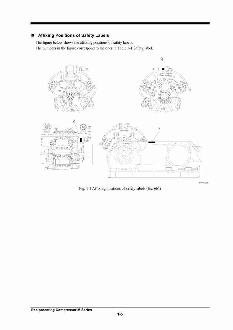
Affixing Positions of Safety Labels
The figure below shows the affixing positions of safety labels.
The numbers in the figure correspond to the ones in Table 1-1 Safety label.
Fig. 1-1 Affixing positions of safety labels (Ex: 6M)
Reciprocating Compressor M Series
1-6
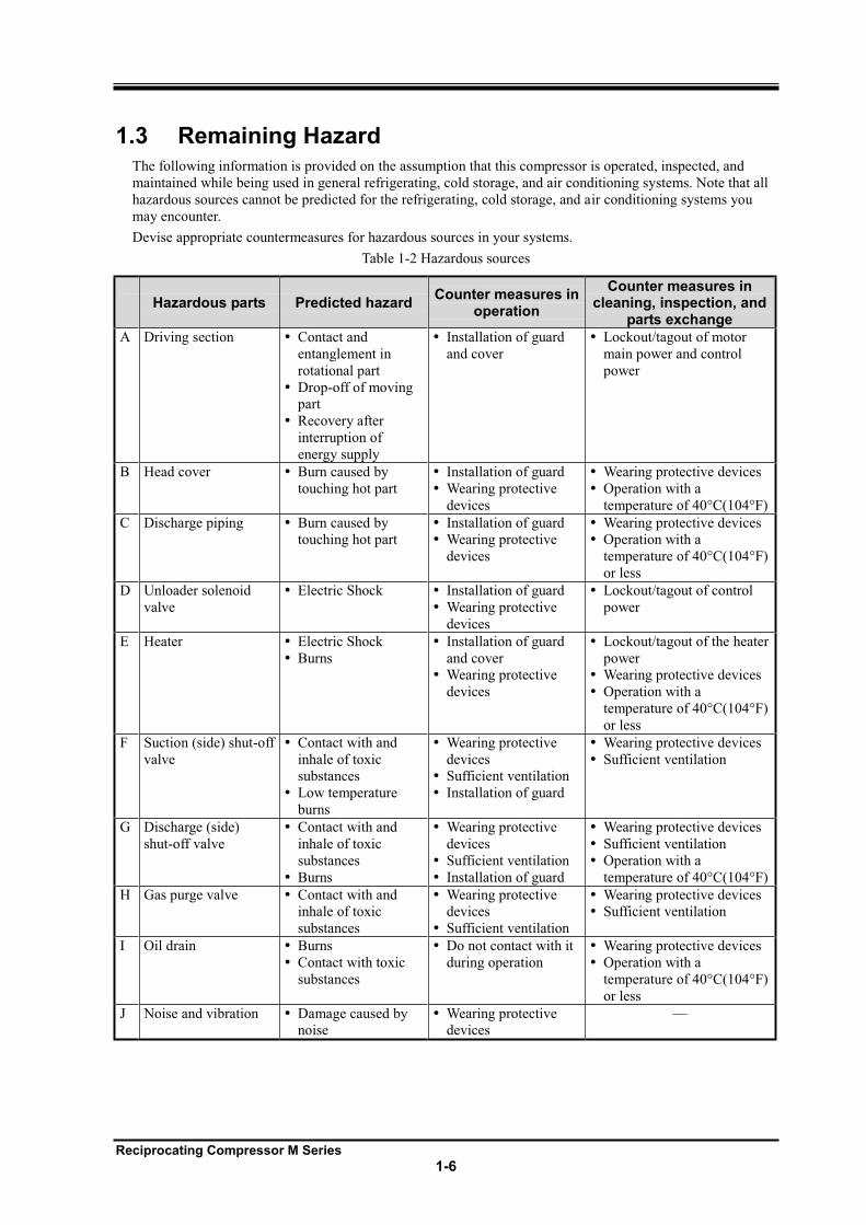
1.3 Remaining Hazard The following information is provided on the assumption that this compressor is operated, inspected, and
maintained while being used in general refrigerating, cold storage, and air conditioning systems. Note that all
hazardous sources cannot be predicted for the refrigerating, cold storage, and air conditioning systems you
may encounter.
Devise appropriate countermeasures for hazardous sources in your systems.
Table 1-2 Hazardous sources
Hazardous parts Predicted hazard Counter measures in
operation
Counter measures in cleaning, inspection, and
parts exchange
A Driving section Contact and
entanglement in
rotational part
Drop-off of moving
part
Recovery after
interruption of
energy supply
Installation of guard
and cover
Lockout/tagout of motor
main power and control
power
B Head cover Burn caused by
touching hot part
Installation of guard
Wearing protective
devices
Wearing protective devices
Operation with a
temperature of 40°C(104°F)
C Discharge piping Burn caused by
touching hot part
Installation of guard
Wearing protective
devices
Wearing protective devices
Operation with a
temperature of 40°C(104°F)
or less
D Unloader solenoid
valve
Electric Shock Installation of guard
Wearing protective
devices
Lockout/tagout of control
power
E Heater Electric Shock
Burns
Installation of guard
and cover
Wearing protective
devices
Lockout/tagout of the heater
power
Wearing protective devices
Operation with a
temperature of 40°C(104°F)
or less
F Suction (side) shut-off
valve
Contact with and
inhale of toxic
substances
Low temperature
burns
Wearing protective
devices
Sufficient ventilation
Installation of guard
Wearing protective devices
Sufficient ventilation
G Discharge (side)
shut-off valve
Contact with and
inhale of toxic
substances
Burns
Wearing protective
devices
Sufficient ventilation
Installation of guard
Wearing protective devices
Sufficient ventilation
Operation with a
temperature of 40°C(104°F)
H Gas purge valve Contact with and
inhale of toxic
substances
Wearing protective
devices
Sufficient ventilation
Wearing protective devices
Sufficient ventilation
I Oil drain Burns
Contact with toxic
substances
Do not contact with it
during operation
Wearing protective devices
Operation with a
temperature of 40°C(104°F)
or less
J Noise and vibration Damage caused by
noise
Wearing protective
devices
Reciprocating Compressor M Series
1-7
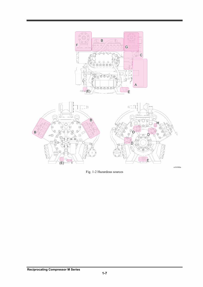
Fig. 1-2 Hazardous sources
Reciprocating Compressor M Series
1-8
1.4 Safety Devices For safe use and protection of the compressor, make sure to attach safety devices to your compressor,
complying with the regulations and the following instructions for each device.
Periodically inspect devices for normal/proper operation. Maintenance must be performed as an important
part for the safety of machine and personal. Provide users of the compressor with necessary information on
the safety devices.
Check the safety devices after turning on the power and before operation of the compressor. If they do not operate normally, immediately take repair or replace safeties before starting compressor.
1.4.1 Emergency Stop Button
Overview/Function/Purpose
Used to stop the compressor immediately if an emergency occurs in the compressor.
Installation Procedures.
On the control board on the compressor and in the operation control room
Stop/Restart Methods
Develop stop and start procedures for the emergency stop button, and make sure available to the users of
this compressor.
Inspection Method/Cycle
The emergency stop button requires test to ensure compressor is shut down when pressed. Ensure this is done
before testing the operation of compressor. Also perform this periodically after compressor is put into service.
1.4.2 Breakers of Motor Main Power and Control Power (with Lockout/Tagout Mechanisms)
Overview/Function/Purpose
When a working on compressor ensure to lockout/tagout main and control power to prevent hazards to
workers (especially during cleaning, maintenance, inspection, and troubleshooting). While the motor main
power and control power are turned "OFF", install lockout/tagout to ensure that no one accidentally turns on
power causing injury to workers.
Methods of Performing and Releasing Lockout/Tagout
Make sure to formulate methods of performing and releasing lockout/tagout referring to the regulations
created by Occupational Safety & Health Administration (OSHA) or local governing body.
Reciprocating Compressor M Series
1-9
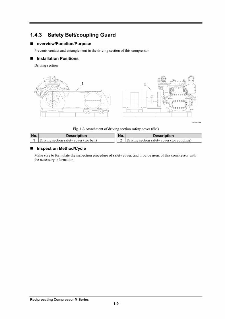
1.4.3 Safety Belt/coupling Guard
overview/Function/Purpose
Prevents contact and entanglement in the driving section of this compressor.
Installation Positions
Driving section
Fig. 1-3 Attachment of driving section safety cover (6M)
No. Description No. Description
1 Driving section safety cover (for belt) 2 Driving section safety cover (for coupling)
Inspection Method/Cycle
Make sure to formulate the inspection procedure of safety cover, and provide users of this compressor with
the necessary information.
Reciprocating Compressor M Series
1-10
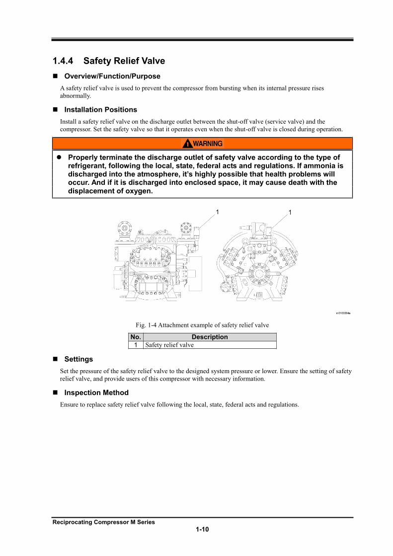
1.4.4 Safety Relief Valve
Overview/Function/Purpose
A safety relief valve is used to prevent the compressor from bursting when its internal pressure rises
abnormally.
Installation Positions
Install a safety relief valve on the discharge outlet between the shut-off valve (service valve) and the
compressor. Set the safety valve so that it operates even when the shut-off valve is closed during operation.
Properly terminate the discharge outlet of safety valve according to the type of refrigerant, following the local, state, federal acts and regulations. If ammonia is discharged into the atmosphere, highly possible that health problems will occur. And if it is discharged into enclosed space, it may cause death with the displacement of oxygen.
Fig. 1-4 Attachment example of safety relief valve
No. Description
1 Safety relief valve
Settings
Set the pressure of the safety relief valve to the designed system pressure or lower. Ensure the setting of safety
relief valve, and provide users of this compressor with necessary information.
Inspection Method
Ensure to replace safety relief valve following the local, state, federal acts and regulations.
Reciprocating Compressor M Series
1-11
1.4.5 Automatic Control and Protection Equipment M compressor
Overview/Function/Purpose
Oil pressure failure protection equipment (OP)
When the oil pressure in compressor (Gauge pressure minus crank case pressure) drops because of
deficiency in the refrigeration oil, clogging of filter, or interfusion of refrigerant, it automatically shuts
off the motor circuit and stops the operation of compressor.
This intended to prevent damage to the compressor from abnormal friction. Can also cause the
unloader mechanism to malfunction
High pressure protection equipment (HP)
When the discharge pressure on compressor becomes abnormally high. HP switch shuts off the motor
circuit automatically to stop the operation of compressor.
Prevents system ruptures and refrigerant leaks.
Control of the compressor capacity: Low pressure control equipment (LP)
The number of capacity control steps in a compressor are determined by the number of cylinders.
Generally two cylinders are considered one bank. Therefore, capacity control of four steps is available
for eight cylinders, three steps for six cylinders, and two steps for four cylinders. Capacity control is
performed by detecting suction pressure a low pressure control switch is used. It automatically controls
opening/closing of the solenoid valve connected to the unloader piston in the capacity control
mechanism of compressor.
Reciprocating Compressor M Series
1-12
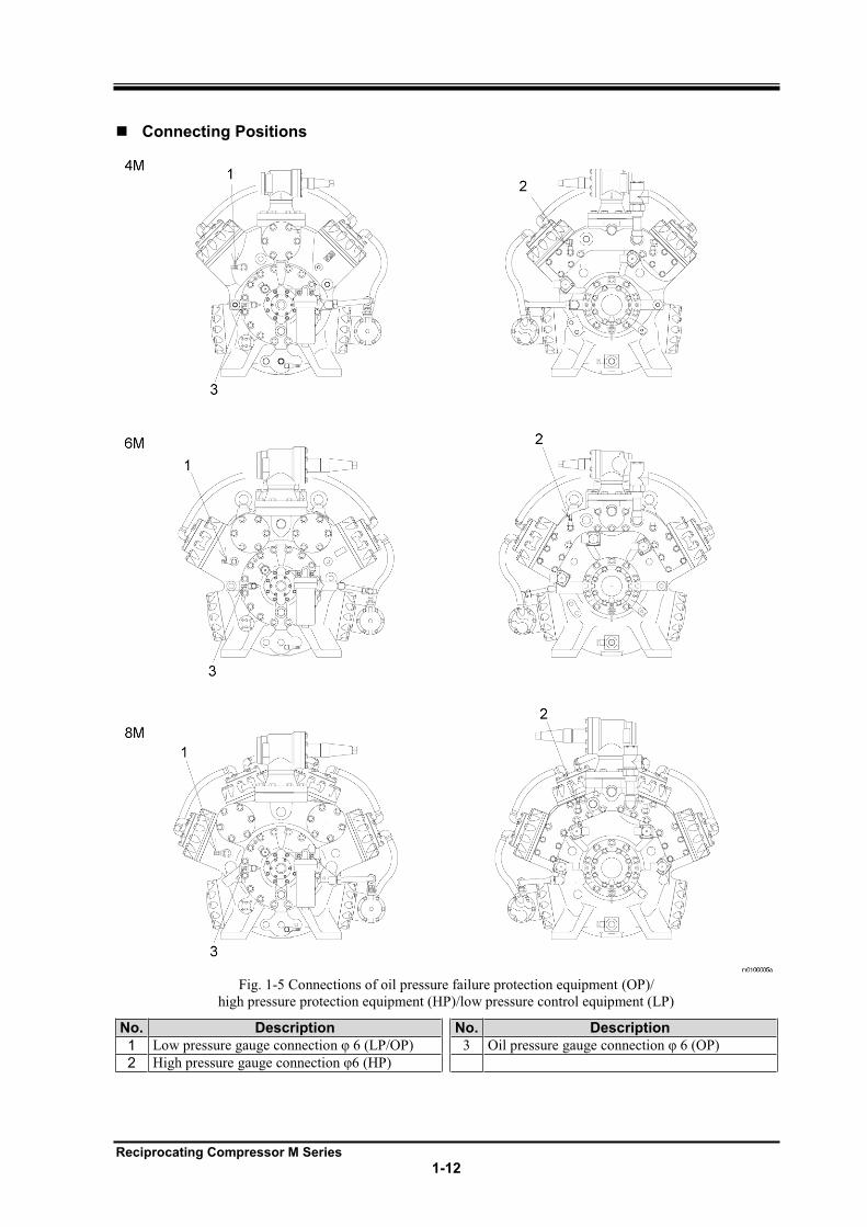
Connecting Positions
Fig. 1-5 Connections of oil pressure failure protection equipment (OP)/
high pressure protection equipment (HP)/low pressure control equipment (LP)
No. Description No. Description
1 3
2
Reciprocating Compressor M Series
1-13
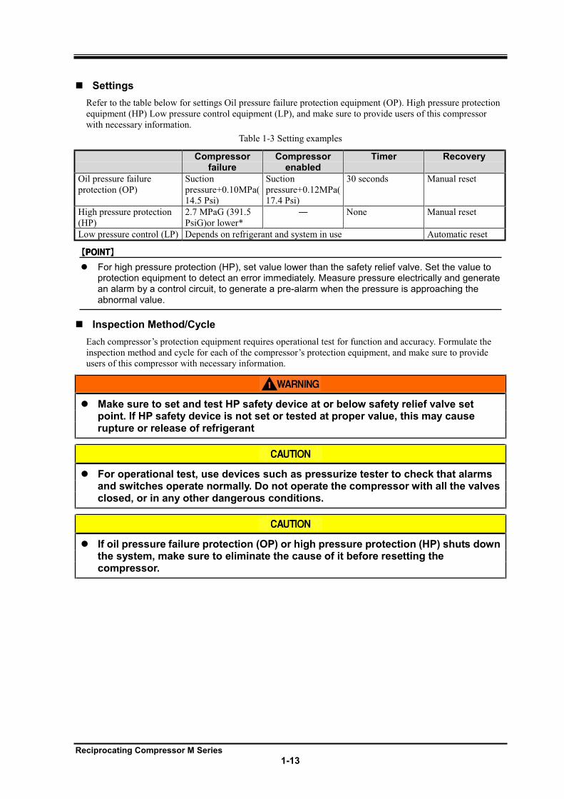
Settings
Refer to the table below for settings Oil pressure failure protection equipment (OP). High pressure protection
equipment (HP) Low pressure control equipment (LP), and make sure to provide users of this compressor
with necessary information.
Table 1-3 Setting examples
Compressor failure
Compressor enabled
Timer Recovery
Oil pressure failure
protection (OP)
Suction
pressure+0.10MPa(
14.5 Psi)
Suction
pressure+0.12MPa(
17.4 Psi)
30 seconds Manual reset
High pressure protection
(HP)
2.7 MPaG (391.5
PsiG)or lower*
None Manual reset
Low pressure control (LP) Depends on refrigerant and system in use Automatic reset
For high pressure protection (HP), set value lower than the safety relief valve. Set the value to protection equipment to detect an error immediately. Measure pressure electrically and generate an alarm by a control circuit, to generate a pre-alarm when the pressure is approaching the abnormal value.
Inspection Method/Cycle
Each compressor protection equipment requires operational test for function and accuracy. Formulate the
inspection method and cycle for each of the compressor protection equipment, and make sure to provide
users of this compressor with necessary information.
Make sure to set and test HP safety device at or below safety relief valve set point. If HP safety device is not set or tested at proper value, this may cause rupture or release of refrigerant
For operational test, use devices such as pressurize tester to check that alarms and switches operate normally. Do not operate the compressor with all the valves closed, or in any other dangerous conditions.
If oil pressure failure protection (OP) or high pressure protection (HP) shuts down the system, make sure to eliminate the cause of it before resetting the compressor.
Reciprocating Compressor M Series
1-14
1.4.6 Compressor Cooling Fluid Temperature Failure Alarm
Overview/Function/Purpose
Prevents the head cover and refrigeration oil from becoming too hot by stopping the compressor.
Installation Positions
Cooling Fluid system
Settings
Formulate the setting of Fluid failure alarm, and make sure to provide users of this compressor with the
necessary information.
Inspection Method/Cycle
The Cooling Fluid failure alarm requires test before operating the compressor and periodically testing after
that. Formulate the inspection procedure of Cooling Fluid Temperature failure alarm, and make sure to
provide users of this compressor with the necessary information.
1.4.7 Oil Heater and Thermometer Switch
Always insure the Oil heater and thermometer switch are completely immersed in oil before applying power. If power is applied to heater then damage to the heater may occur, destroying the element from dry burn.
Overview/Function/Purpose
The oil heater is a cartridge type covered heater. It is pressure-proof sealed type with heating wires wrapped
with insulator and externally sealed with stainless tube.
The oil heater is used to prevent refrigerant from dissolving in oil or condensing in the crank case during the
off cycle of the compressor.
Installation Positions
The thermoswitch which controls temperature of heater is attached inside the heater.
Settings
Formulate the setting of thermo switch, and make sure to provide users of this compressor with the necessary
information.
Inspection Method/Cycle
The thermo switch requires set up and testing before operating the compressor and periodically after that.
Formulate the inspection procedure of the thermoswitch, and make sure to provide users of this compressor
with the necessary information.
Reciprocating Compressor M Series
1-15
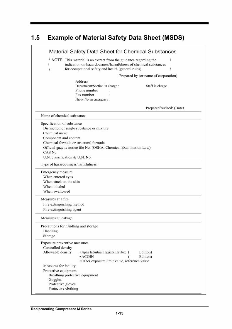
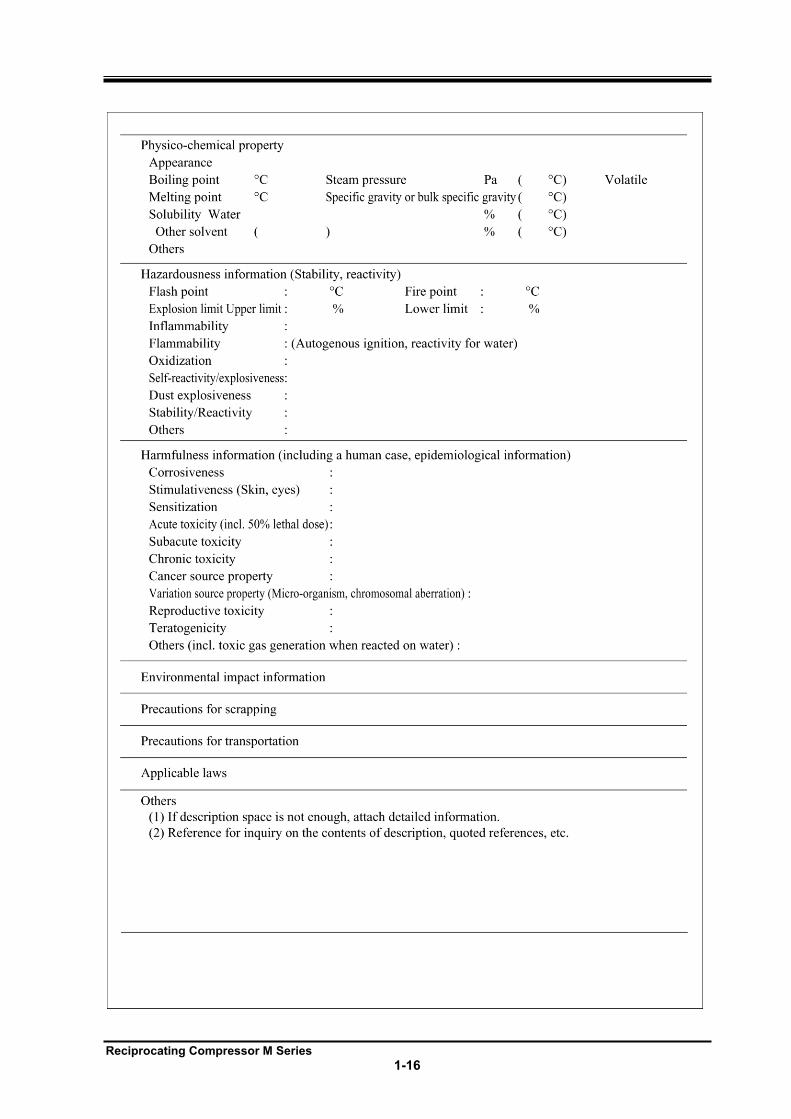
1.5 Example of Material Safety Data Sheet (MSDS)
Reciprocating Compressor M Series
1-16
Reciprocating Compressor M Series
2-1
2 Configuration and Specification of Compressor
2.1 Configuration of Compressor
2.1.1 Overall View of Compressor
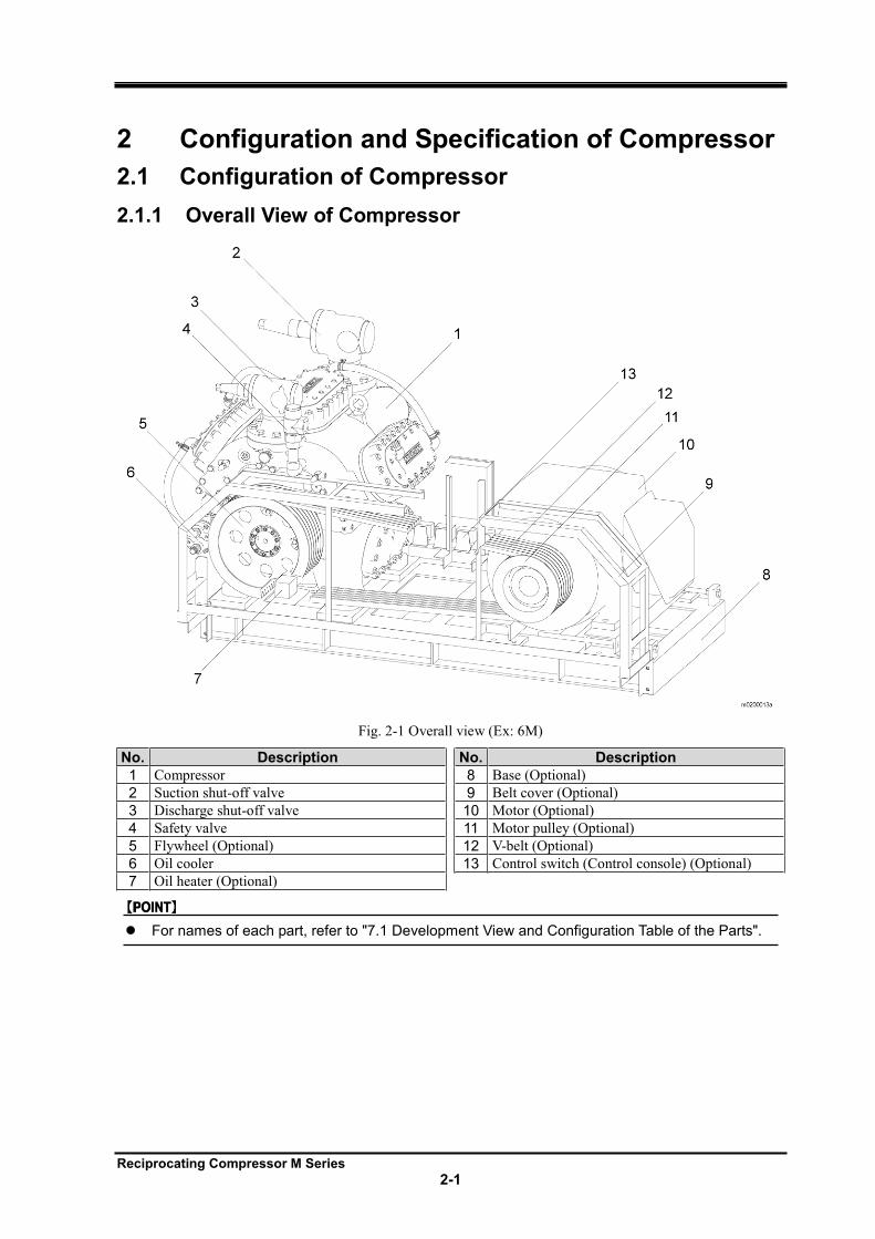
Fig. 2-1 Overall view (Ex: 6M)
No. Description No. Description
1 Compressor 8 Base (Optional)
2 Suction shut-off valve 9 Belt cover (Optional)
3 Discharge shut-off valve 10 Motor (Optional)
4 Safety valve 11 Motor pulley (Optional)
5 Flywheel (Optional) 12 V-belt (Optional)
6 Oil cooler 13 Control switch (Control console) (Optional)
7 Oil heater (Optional)
For names of each part, refer to "7.1 Development View and Configuration Table of the Parts".
Reciprocating Compressor M Series
2-2
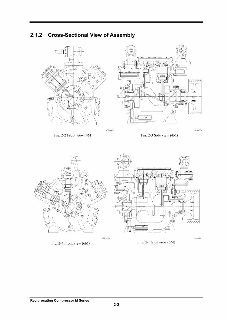
2.1.2 Cross-Sectional View of Assembly
Fig. 2-2 Front view (4M)
Fig. 2-3 Side view (4M)
Fig. 2-4 Front view (6M)
Fig. 2-5 Side view (6M)
Reciprocating Compressor M Series
2-3
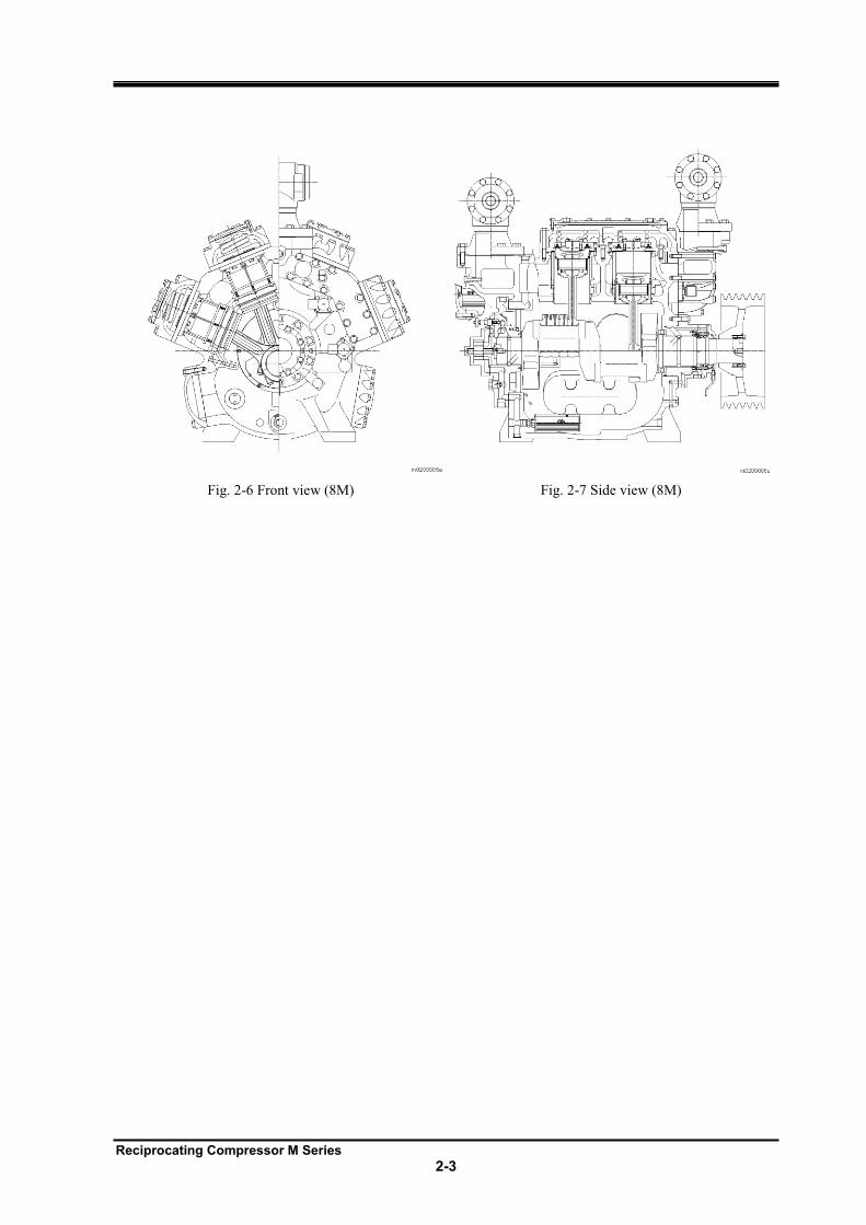
Fig. 2-6 Front view (8M)
Fig. 2-7 Side view (8M)
Reciprocating Compressor M Series
2-4
2.1.3 Oil Supply Mechanism
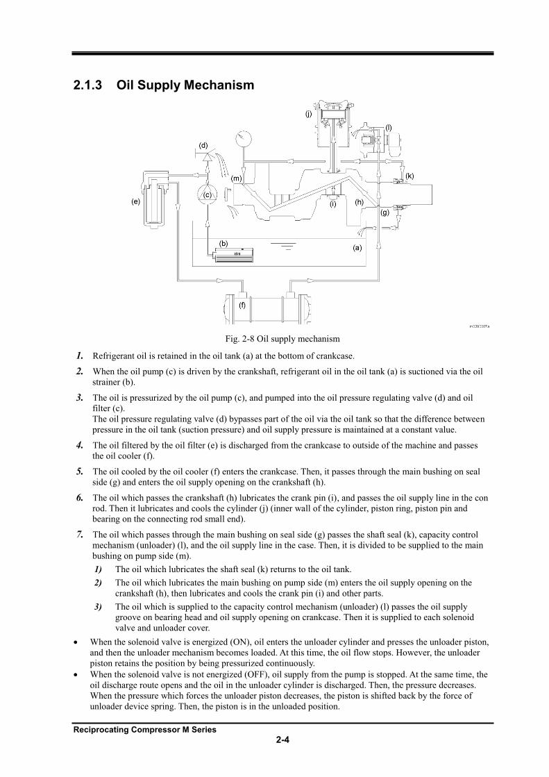
Fig. 2-8 Oil supply mechanism
1. Refrigerant oil is retained in the oil tank (a) at the bottom of crankcase.
2. When the oil pump (c) is driven by the crankshaft, refrigerant oil in the oil tank (a) is suctioned via the oil
strainer (b).
3. The oil is pressurized by the oil pump (c), and pumped into the oil pressure regulating valve (d) and oil
filter (c).
The oil pressure regulating valve (d) bypasses part of the oil via the oil tank so that the difference between
pressure in the oil tank (suction pressure) and oil supply pressure is maintained at a constant value.
4. The oil filtered by the oil filter (e) is discharged from the crankcase to outside of the machine and passes
the oil cooler (f).
5. The oil cooled by the oil cooler (f) enters the crankcase. Then, it passes through the main bushing on seal
side (g) and enters the oil supply opening on the crankshaft (h).
6. The oil which passes the crankshaft (h) lubricates the crank pin (i), and passes the oil supply line in the con
rod. Then it lubricates and cools the cylinder (j) (inner wall of the cylinder, piston ring, piston pin and
bearing on the connecting rod small end).
7. The oil which passes through the main bushing on seal side (g) passes the shaft seal (k), capacity control
mechanism (unloader) (l), and the oil supply line in the case. Then, it is divided to be supplied to the main
bushing on pump side (m).
1) The oil which lubricates the shaft seal (k) returns to the oil tank.
2) The oil which lubricates the main bushing on pump side (m) enters the oil supply opening on the
crankshaft (h), then lubricates and cools the crank pin (i) and other parts.
3) The oil which is supplied to the capacity control mechanism (unloader) (l) passes the oil supply
groove on bearing head and oil supply opening on crankcase. Then it is supplied to each solenoid
valve and unloader cover.
When the solenoid valve is energized (ON), oil enters the unloader cylinder and presses the unloader piston,
and then the unloader mechanism becomes loaded. At this time, the oil flow stops. However, the unloader
piston retains the position by being pressurized continuously.
When the solenoid valve is not energized (OFF), oil supply from the pump is stopped. At the same time, the
oil discharge route opens and the oil in the unloader cylinder is discharged. Then, the pressure decreases.
When the pressure which forces the unloader piston decreases, the piston is shifted back by the force of
unloader device spring. Then, the piston is in the unloaded position.
Reciprocating Compressor M Series
2-5
2.1.4 Unloader Mechanism
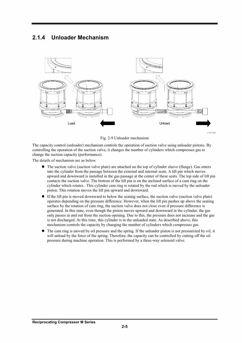
Fig. 2-9 Unloader mechanism
The capacity control (unloader) mechanism controls the operation of suction valve using unloader pistons. By
controlling the operation of the suction valve, it changes the number of cylinders which compresses gas to
change the suction capacity (performance).
The details of mechanism are as below.
The suction valve (suction valve plate) are attached on the top of cylinder sleeve (flange). Gas enters
into the cylinder from the passage between the external and internal seats. A lift pin which moves
upward and downward is installed in the gas passage at the center of these seats. The top side of lift pin
contacts the suction valve. The bottom of the lift pin is on the inclined surface of a cam ring on the
cylinder which rotates.. This cylinder cam ring is rotated by the rod which is moved by the unloader
piston. This rotation moves the lift pin upward and downward.
If the lift pin is moved downward to below the seating surface, the suction valve (suction valve plate)
operates depending on the pressure difference. However, when the lift pin pushes up above the seating
surface by the rotation of cam ring, the suction valve does not close even if pressure difference is
generated. In this state, even though the piston moves upward and downward in the cylinder, the gas
only passes in and out from the suction opening. Due to this, the pressure does not increase and the gas
is not discharged. At this time, this cylinder is in the unloaded state. As described above, this
mechanism controls the capacity by changing the number of cylinders which compresses gas.
The cam ring is moved by oil pressure and the spring. If the unloader piston is not pressurized by oil, it
will unload by the force of the spring. Therefore, the capacity can be controlled by cutting off the oil
pressure during machine operation. This is performed by a three-way solenoid valve.
Reciprocating Compressor M Series
2-6
2.2 Specification of Compressor
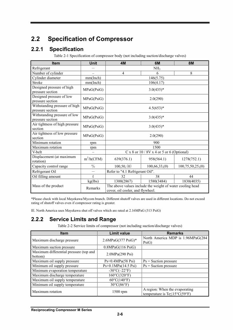
2.2.1 Specification Table 2-1 Specification of compressor body (not including suction/discharge valves)
Item Unit 4M 6M 8M
Refrigerant NH3
Number of cylinder 4 6 8
Cylinder diameter mm(Inch) 146(5.75)
Stroke mm(Inch) 106(4.17)
Designed pressure of high
pressure section MPaG(PsiG) 3.0(435)*
Designed pressure of low
pressure section MPaG(PsiG) 2.0(290)
Withstanding pressure of high
pressure section MPaG(PsiG) 4.5(653)*
Withstanding pressure of low
pressure section MPaG(PsiG) 3.0(435)*
Air tightness of high pressure
section MPaG(PsiG) 3.0(435)*
Air tightness of low pressure
section MPaG(PsiG) 2.0(290)
Minimum rotation rpm 900
Maximum rotation rpm 1500
V-belt C x 8 or 10 / 8V x 4 or 5 or 6 (Optional)
Displacement (at maximum
rotation) m
3/h(CFM) 639(376.1) 958(564.1) 1278(752.1)
Capacity control range 100,50, 0 100,66,33,(0) 100,75,50,25,(0)
Refrigerant Oil Refer to "4.1 Refrigerant Oil".
Oil filling amount 32 38 44
Mass of the product
kg(lbs) 1300(2867) 1580(3484) 1830(4035)
Remarks The above values include the weight of water cooling head
cover, oil cooler, and flywheel.
*Please check with local Mayekawa/Mycom branch. Different shutoff valves are used in different locations. Do not exceed
rating of shutoff valves even if compressor rating is greater.
IE. North America uses Mayekawa shut off valves which are rated at 2.16MPaG (313 PsiG)
2.2.2 Service Limits and Range Table 2-2 Service limits of compressor (not including suction/discharge valves)
Item Limit value Remarks
Maximum discharge pressure 2.6MPaG(377 PsiG)* North America MDP is 1.96MPaG(284
PsiG)
Maximum suction pressure 0.8MPaG(116 PsiG)
Maximum differential pressure (top and
bottom) 2.0MPa(290 Psi)
Maximum oil supply pressure Ps+0.4MPa(58 Psi) Ps = Suction pressure
Minimum oil supply pressure Ps+0.1MPa(14.5 Psi) Ps = Suction pressure
Minimum evaporation temperature -30°C( 22°F)
Maximum discharge temperature 160°C(320°F)
Maximum oil supply temperature 60°C(140°F)
Minimum oil supply temperature 30°C(86°F)
Maximum rotation 1500 rpm A region: When the evaporating
15°C(59°F)
Reciprocating Compressor M Series
2-7
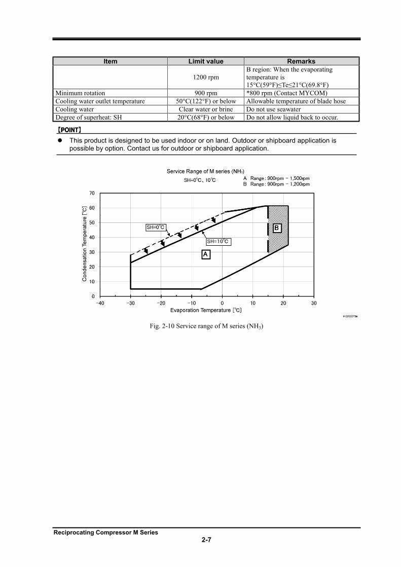
Item Limit value Remarks
1200 rpm
B region: When the evaporating
temperature is
15°C(59°F) 21°C(69.8°F)
Minimum rotation 900 rpm *800 rpm (Contact MYCOM)
Cooling water outlet temperature 50°C(122°F) or below Allowable temperature of blade hose
Cooling water Clear water or brine Do not use seawater
Degree of superheat: SH 20°C(68°F) or below Do not allow liquid back to occur.
This product is designed to be used indoor or on land. Outdoor or shipboard application is possible by option. Contact us for outdoor or shipboard application.
Fig. 2-10 Service range of M series (NH3)
Reciprocating Compressor M Series
2-8
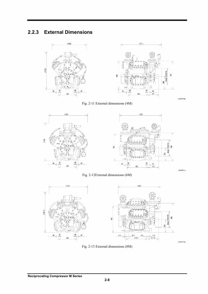
2.2.3 External Dimensions
Fig. 2-11 External dimensions (4M)
Fig. 2-12External dimensions (6M)
Fig. 2-13 External dimensions (8M)
Reciprocating Compressor M Series
2-9
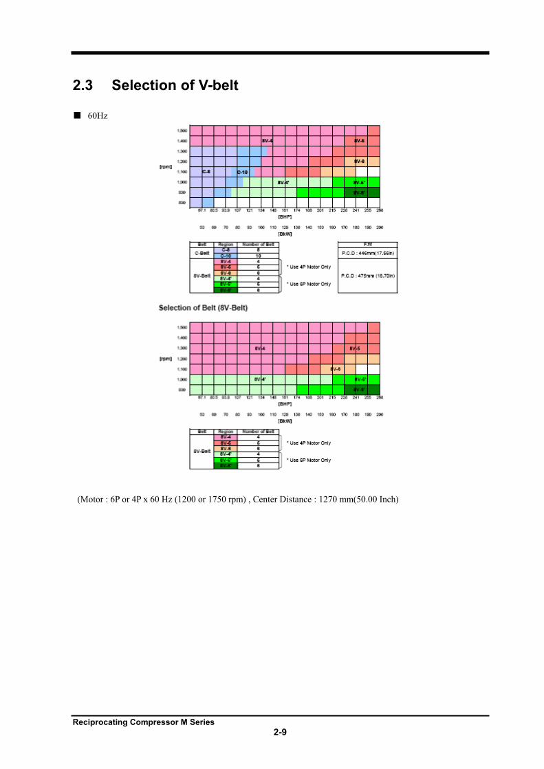
2.3 Selection of V-belt
60Hz
(Motor : 6P or 4P x 60 Hz (1200 or 1750 rpm) , Center Distance : 1270 mm(50.00 Inch)
Reciprocating Compressor M Series
3-1
3 Installation
3.1 Safety Precautions for Installation
This chapter is based on the assumption that the compressor is installed for the purpose of refrigeration, cold storage, and air conditioning systems, recreational systems. If the specifications of your system are different, refer to this chapter and consider safety, before operation. If there are any questions, please contact your local sales offices or service centers.
Insure that installation work is performed by a qualified personal or contracting company. Make sure
that the work is performed in compliance with local laws and ordinances.
Read this chapter and related documents, and fully understand their contents before performing
installation.
Electrical works should be performed only by those certified by local governing body.
Do not place any part of your body under the lifted compressor.
Reciprocating Compressor M Series
3-2
3.2 Installation Works
3.2.1 Unpacking Check that there is no abnormality such as damage on the compressor.
If there are abnormalities or deficiencies on the compressor, please contact your local sales offices or service centers immediately.
Unnecessary packing materials should be discarded according to the laws and ordinances, or your company's rules.
3.2.2 Storage Perform the following to store the compressor before installation.
Store it indoors.
Charge nitrogen gas into the compressor and seal it.
Nitrogen gas has been charged into the compressor at packing to prevent from rusting.
3.2.3 Transfer
Dropping of the lifted compressor may cause death or serious injury. Do not stand under the lifted compressor.
1. For lifting the compressor within the safety limit, use lifting equipment and tools appropriate for the
weight of compressor.
2. Leave sufficient space for lifting.
3. Always check wire rope before using. Thoroughly check for kink, knot, or breakage. Do not perform
lifting before checking the wire rope. If there are any problems, do not lift until equipment has been
confirmed safe.
4. For lifting the compressor individually, hook the wire rope on the lifting bolt of compressor.
5. For lifting the compressor with base and motor, hook the wire rope on the lifting bolt and the base of
compressor. Do not use the lifting bolt on the motor.
6. Check path of compressor installation to make sure it is free of obstacles.
7. Check that the hook is above the center of gravity of the unit before lifting.
8. Direct all the workers to stay clear of the work site before lifting.
9. Before lifting the compressor notify all workers in area of dangers during lifting process. Remove all
nonessential personal from area till lift is complete.
10. Wind up the wire rope slowly until shortly before the compressor leaves from the ground.
11. Remove all tension slowly until the compressor leaves the ground, and check that the compressor is
balanced. If it is tilted, lower compressor and correct the tilt. Repeat process till compressor lifts level.
12. Lift the compressor slowly. If it is lifted rapidly, it may damage the lifting tools such as wire rope or a part
of the compressor.
13. When moving the lifted compressor, always use tag line/induction rope.
14. Do not lift the compressor over head unless absolutely necessary.
15. Do not lower the compressor and block the passage.
Reciprocating Compressor M Series
3-3
16. Remove obstructions before lowering the compressor onto the ground. The compressor should not be tilted
or unstable.
17. Before lowering the compressor, notify others.
18. When lowering the compressor onto two or more blocks, align the tops of blocks so that the compressor
becomes stable horizontally on them.
19. Lower the lifted compressor slowly so that it is not damaged by impact on the ground.
Reciprocating Compressor M Series
3-4
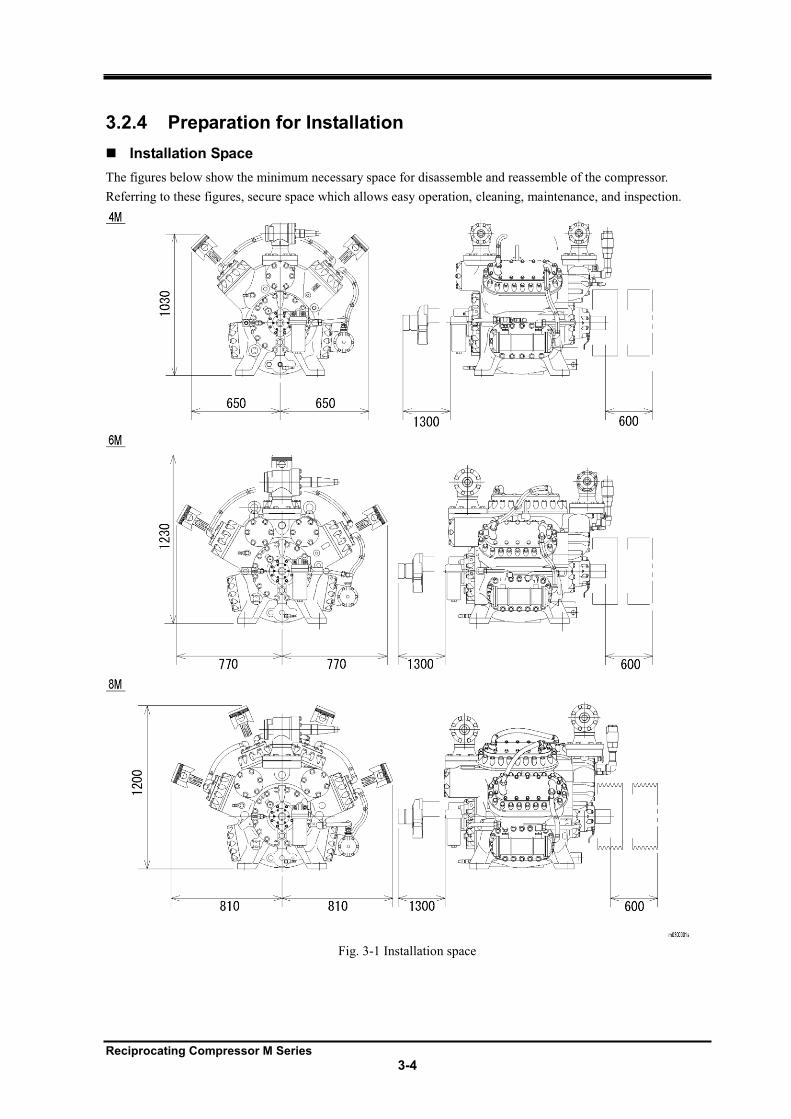
3.2.4 Preparation for Installation
Installation Space
The figures below show the minimum necessary space for disassemble and reassemble of the compressor.
Referring to these figures, secure space which allows easy operation, cleaning, maintenance, and inspection.
Fig. 3-1 Installation space
Reciprocating Compressor M Series
3-5
Illumination
Prepare illumination devices which allow easy operation, cleaning, maintenance, and inspection.
Ventilation
If natural ventilation is insufficient, install ventilation fans according to the regulations.
Cooling Water
Referring to chapter 7, secure cooling water necessary for your system.
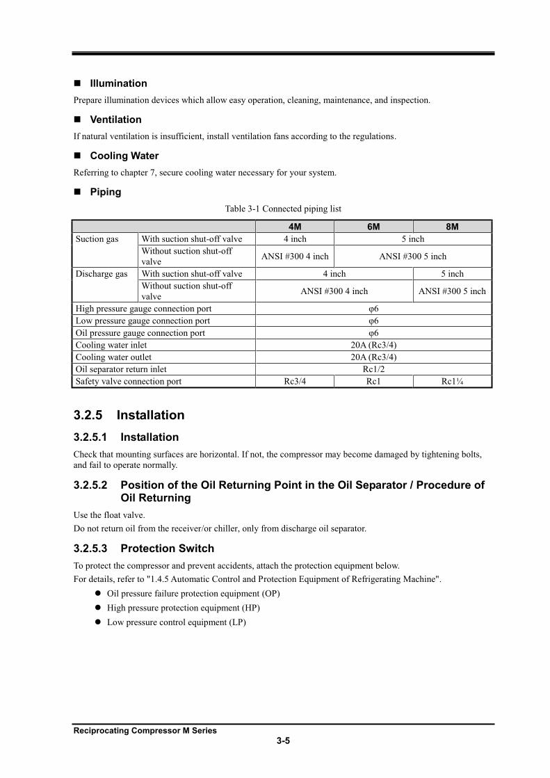
Piping
Table 3-1 Connected piping list
4M 6M 8M
Suction gas With suction shut-off valve 4 inch 5 inch
Without suction shut-off
valve ANSI #300 4 inch ANSI #300 5 inch
Discharge gas With suction shut-off valve 4 inch 5 inch
Without suction shut-off
valve ANSI #300 4 inch ANSI #300 5 inch
High pressure gauge connection port
Low pressure gauge connection port
Oil pressure gauge connection port
Cooling water inlet 20A (Rc3/4)
Cooling water outlet 20A (Rc3/4)
Oil separator return inlet Rc1/2
Safety valve connection port Rc3/4 Rc1 Rc1¼
3.2.5 Installation
3.2.5.1 Installation
Check that mounting surfaces are horizontal. If not, the compressor may become damaged by tightening bolts,
and fail to operate normally.
3.2.5.2 Position of the Oil Returning Point in the Oil Separator / Procedure of Oil Returning
Use the float valve.
Do not return oil from the receiver/or chiller, only from discharge oil separator.
3.2.5.3 Protection Switch
To protect the compressor and prevent accidents, attach the protection equipment below.
For details, refer to "1.4.5 Automatic Control and Protection Equipment of Refrigerating Machine".
Oil pressure failure protection equipment (OP)
High pressure protection equipment (HP)
Low pressure control equipment (LP)
Reciprocating Compressor M Series
3-6
3.2.5.4 Centering of the Compressor/Driving Machine and Attachment of the V / C-belt
To replace the V / C-belt with a new one, purchase the same set of belt as the current one, and replace the whole set at once. Even if their nominal dimensions are the same, their actual lengths may slightly differ. In such case, operation force is applied only to the short belt. This may cause wear of the belt and abnormal vibration. Also, if old and new belts are used together, the difference of their wear amounts may cause abnormal vibration.
V / Cbelt should be free from machine oil and lubrication oil. If those oils adhere to V / C-belt, wipe them off.
V / C-belts are set to proper tension on shipment. During normal operation belts will stretch and should be tightened to ensure long life of all drive parts.
Centering and Attachment of V /C-belt
If the compressor has a common base, centering is performed on the V /C-belt before shipment. However, check
the center again after installation.
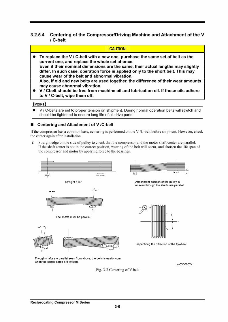
1. Straight edge on the side of pulley to check that the compressor and the motor shaft center are parallel.
If the shaft center is not in the correct position, wearing of the belt will occur, and shorten the life span of
the compressor and motor by applying force to the bearings.
Fig. 3-2 Centering of V-belt
Reciprocating Compressor M Series
3-7
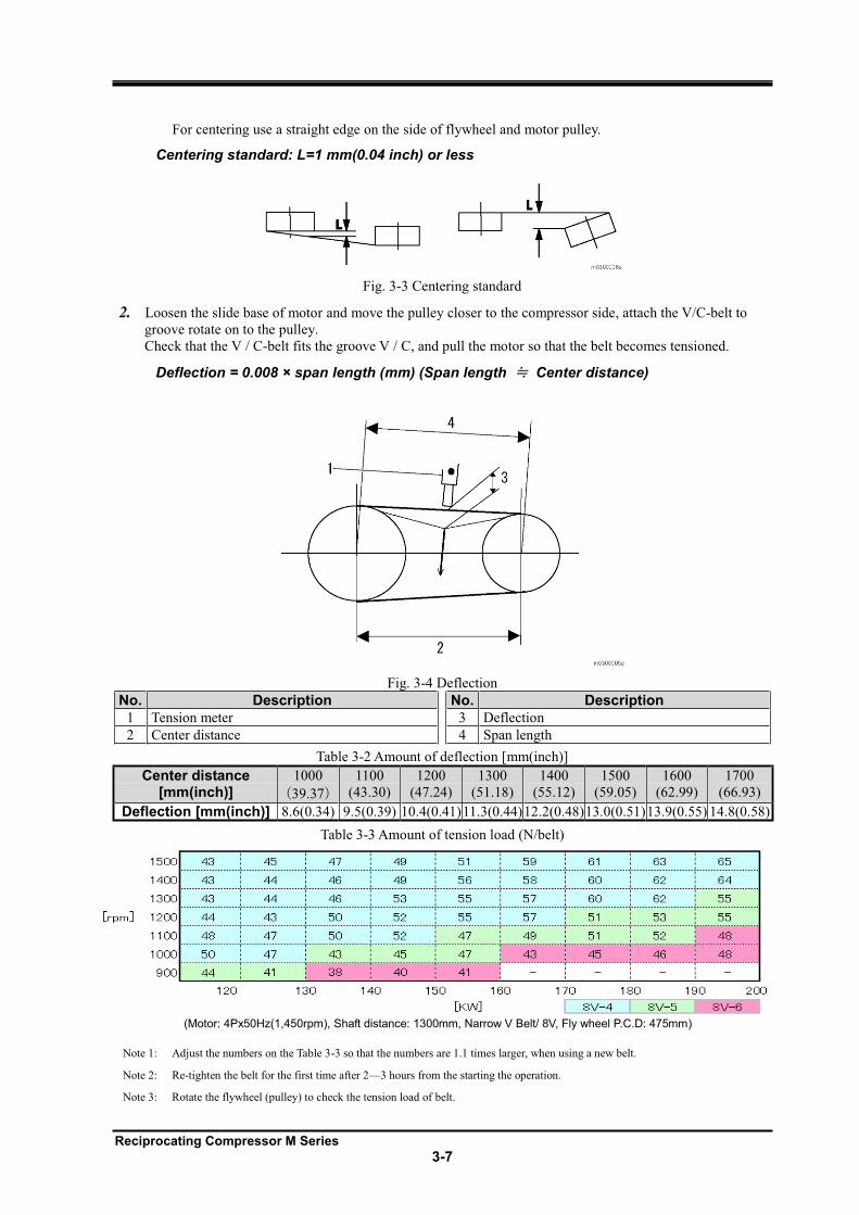
For centering use a straight edge on the side of flywheel and motor pulley.
Centering standard: L=1 mm(0.04 inch) or less
Fig. 3-3 Centering standard
2. Loosen the slide base of motor and move the pulley closer to the compressor side, attach the V/C-belt to
groove rotate on to the pulley.
Check that the V / C-belt fits the groove V / C, and pull the motor so that the belt becomes tensioned.
Deflection = 0.008 × span length (mm) (Span length Center distance)
Fig. 3-4 Deflection
No. Description No. Description
1 Tension meter 3 Deflection
2 Center distance 4 Span length
Table 3-2 Amount of deflection [mm(inch)]
Table 3-3 Amount of tension load (N/belt)
Note 1: Adjust the numbers on the Table 3-3 so that the numbers are 1.1 times larger, when using a new belt.
Note 2: Re-tighten the belt for the first time after 2 3 hours from the starting the operation.
Note 3: Rotate the flywheel (pulley) to check the tension load of belt.
Center distance [mm(inch)]
1000
39.37
1100
(43.30)
1200
(47.24)
1300
(51.18)
1400
(55.12)
1500
(59.05)
1600
(62.99)
1700
(66.93)
Deflection [mm(inch)] 8.6(0.34) 9.5(0.39) 10.4(0.41) 11.3(0.44) 12.2(0.48) 13.0(0.51) 13.9(0.55) 14.8(0.58)
(Motor: 4Px50Hz(1,450rpm), Shaft distance: 1300mm, Narrow V Belt/ 8V, Fly wheel P.C.D: 475mm)
Reciprocating Compressor M Series
3-8
Note 4: When the belt is under the minimum tension load, make sure that the belt does not move excessively by operation, because the load fluctuates due to the load conditions.
After replacing the belt, operate the compressor for 2 to 3 hours, initial tension and friction will occur on the new belt. Due to these and other causes such as peel-off of coating from flywheel, the tension load of belts may decrease drastically to less than the minimum. If the belt is continuously used in this condition, the service life of belt will be shortened by slipping. In addition to this, defects may occur such as excessive movement of belt, overturn and deviation caused by wear of belt on one side. Make sure to re-tighten the belt soon after operation.
If the belt is replaced with a new one, operate the compressor with the new belt for 24 48 hours and check the tension again.
Centering and Installation of Couplings
The installation positions of the compressor and motor are a product of the center distance of the couplings. Also,
the difference of center core heights is within 0.1mm(0.0043 inches) by machining process of frames.
To align the center shafts, correct the vertical and horizontal deviations.
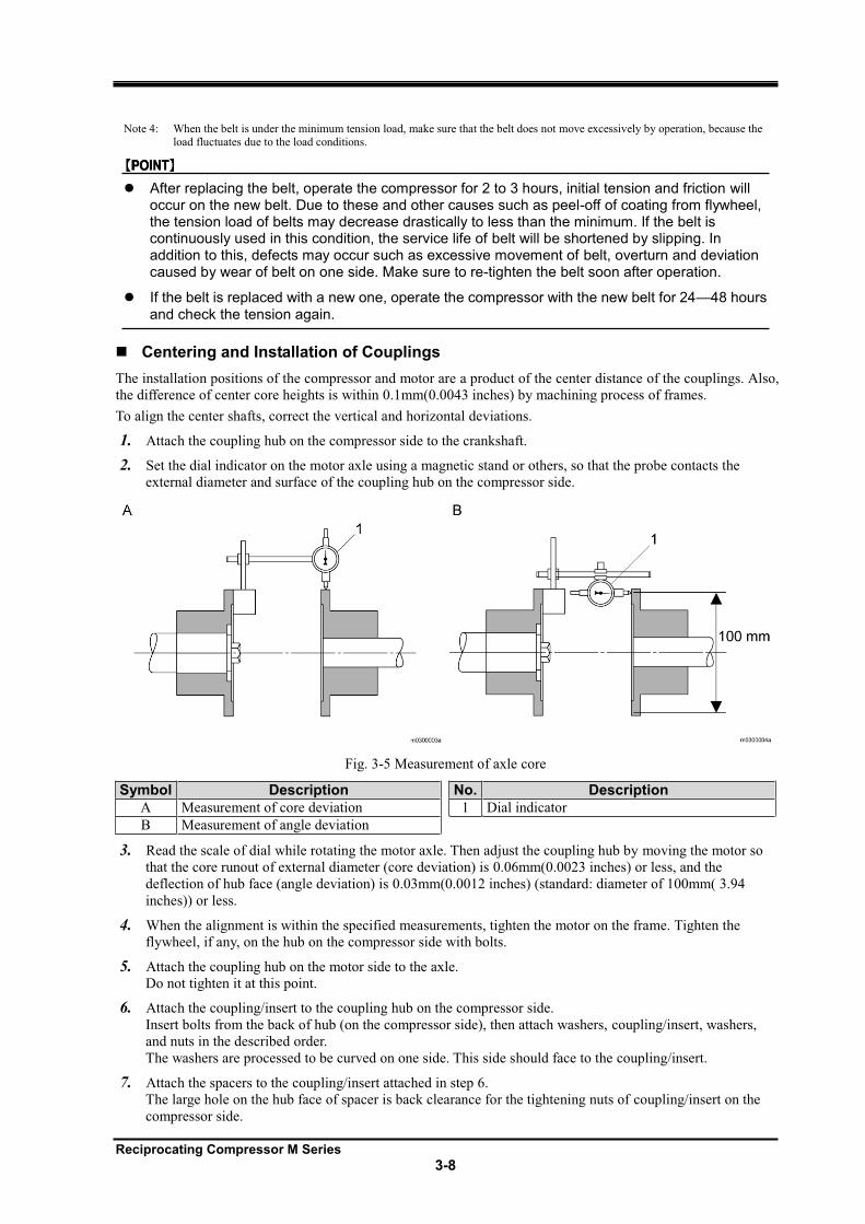
1. Attach the coupling hub on the compressor side to the crankshaft.
2. Set the dial indicator on the motor axle using a magnetic stand or others, so that the probe contacts the
external diameter and surface of the coupling hub on the compressor side.
Fig. 3-5 Measurement of axle core
Symbol Description No. Description
A Measurement of core deviation 1 Dial indicator
B Measurement of angle deviation
3. Read the scale of dial while rotating the motor axle. Then adjust the coupling hub by moving the motor so
that the core runout of external diameter (core deviation) is 0.06mm(0.0023 inches) or less, and the
deflection of hub face (angle deviation) is 0.03mm(0.0012 inches) (standard: diameter of 100mm( 3.94
inches)) or less.
4. When the alignment is within the specified measurements, tighten the motor on the frame. Tighten the
flywheel, if any, on the hub on the compressor side with bolts.
5. Attach the coupling hub on the motor side to the axle.
Do not tighten it at this point.
6. Attach the coupling/insert to the coupling hub on the compressor side.
Insert bolts from the back of hub (on the compressor side), then attach washers, coupling/insert, washers,
and nuts in the described order.
The washers are processed to be curved on one side. This side should face to the coupling/insert.
7. Attach the spacers to the coupling/insert attached in step 6.
The large hole on the hub face of spacer is back clearance for the tightening nuts of coupling/insert on the
compressor side.
Reciprocating Compressor M Series
3-9
8. Retain the coupling/insert on the motor side on the spacer.
9. When attaching the hub and coupling/insert on the motor side, move the hub to the gap in which the
washers fit, and adjust the interval between the coupling hubs.
If the washers do not fit in easily, or there are gaps between the coupling/insert, washers, and hub face,
force in the axle direction (thrust) is applied. Prevent this thrust from applying.
10. Tighten the hub on the motor side on the axle.
11. Tighten all the nuts at the specified torque again.
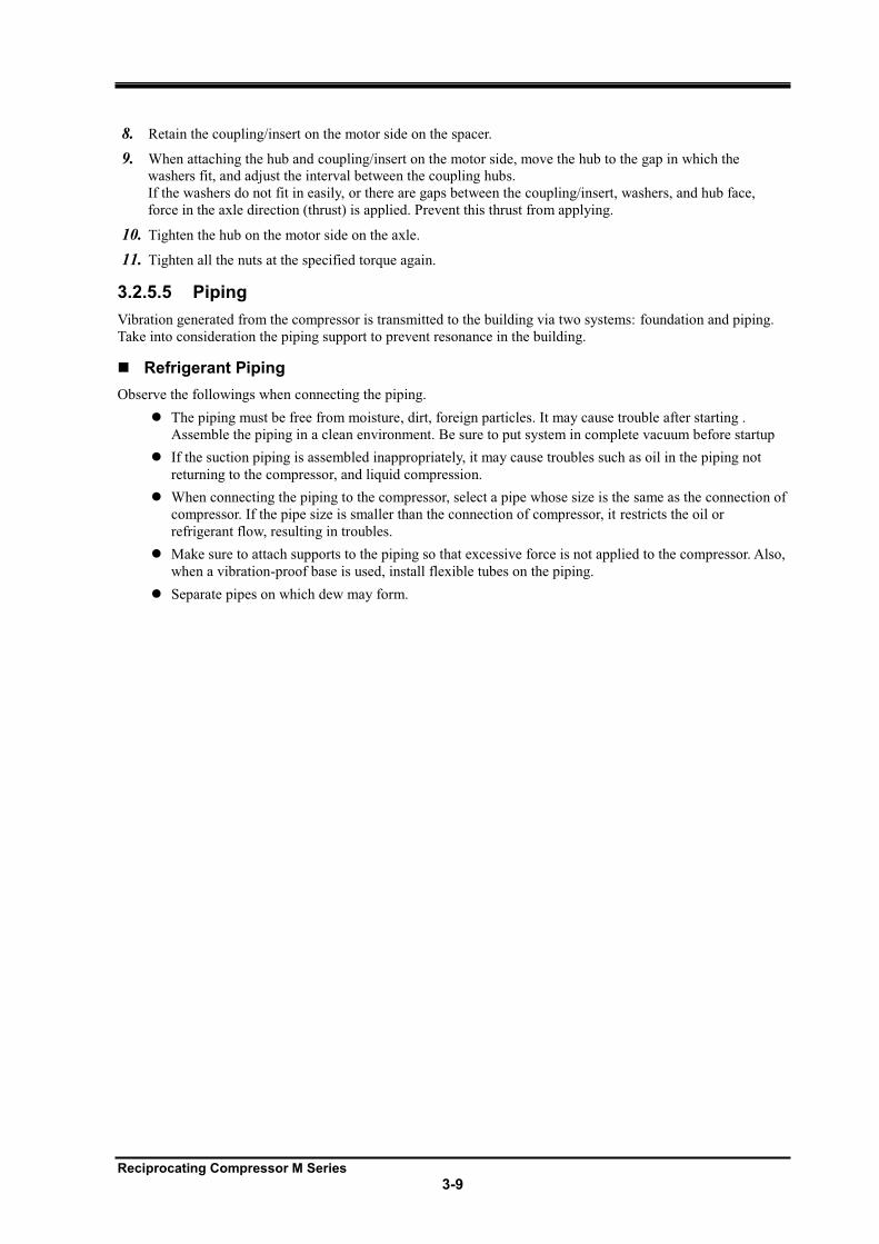
3.2.5.5 Piping
Vibration generated from the compressor is transmitted to the building via two systems: foundation and piping.
Take into consideration the piping support to prevent resonance in the building.
Refrigerant Piping
Observe the followings when connecting the piping.
The piping must be free from moisture, dirt, foreign particles. It may cause trouble after starting .
Assemble the piping in a clean environment. Be sure to put system in complete vacuum before startup
If the suction piping is assembled inappropriately, it may cause troubles such as oil in the piping not
returning to the compressor, and liquid compression.
When connecting the piping to the compressor, select a pipe whose size is the same as the connection of
compressor. If the pipe size is smaller than the connection of compressor, it restricts the oil or
refrigerant flow, resulting in troubles.
Make sure to attach supports to the piping so that excessive force is not applied to the compressor. Also,
when a vibration-proof base is used, install flexible tubes on the piping.
Separate pipes on which dew may form.
Reciprocating Compressor M Series
3-10
Cooling Water Piping
Do not limit the flow in the cooling water system from the oil cooler to the head jacket. This is dangerous because the difference of pressure loss (resistance) restricts the cooling water flow, resulting in failure to cool necessary sections.
Always flow cooling water during operation of compressor.
For compressor with water cooled type oil cooler and water cooling head cover, observe the following when
performing piping for cooling water.
For automatic operation, attach solenoid valves so that cooling water does not flow while the motor is
not in operation. If cooling water flows while the motor is stopped, refrigerant in the compressor is
condensed, resulting in increase of oil consumption, and possible compressor damage from hydraulic.
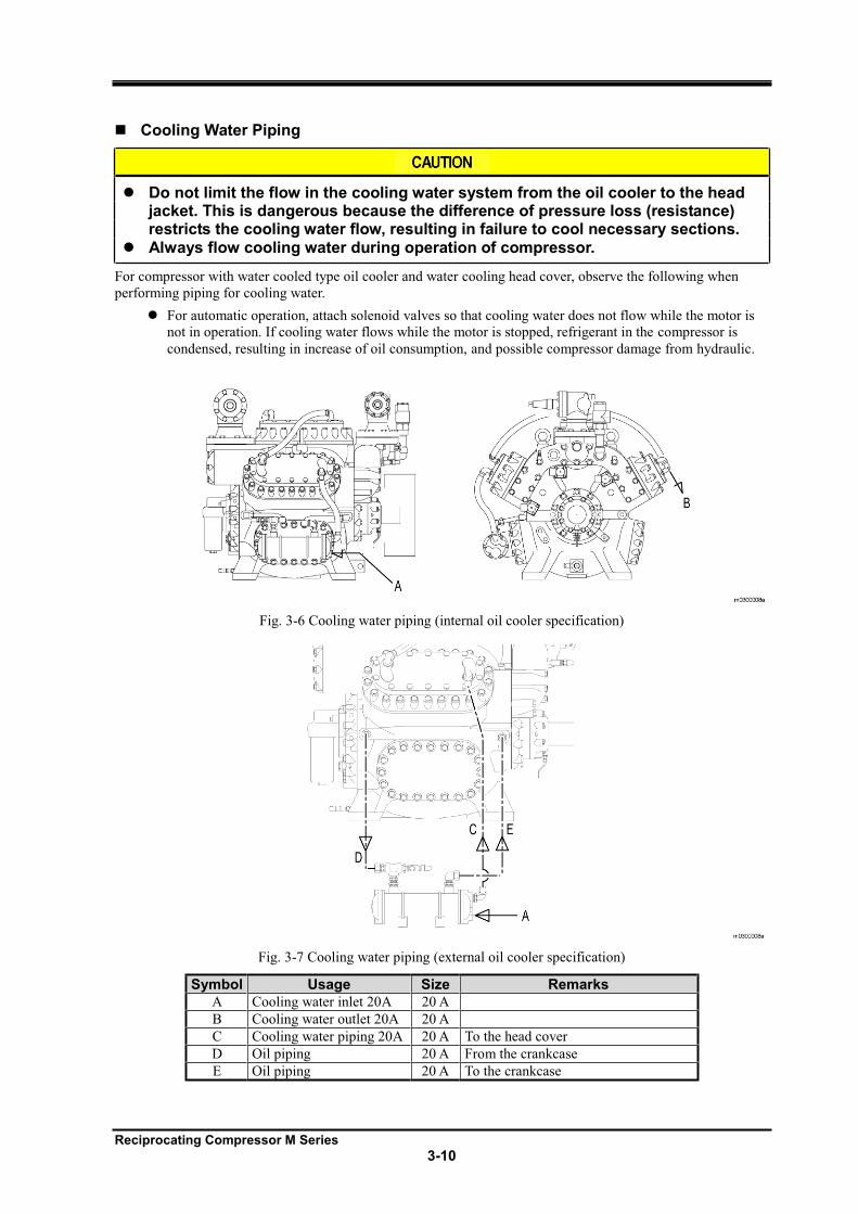
Fig. 3-6 Cooling water piping (internal oil cooler specification)
Fig. 3-7 Cooling water piping (external oil cooler specification)
Symbol Usage Size Remarks
A Cooling water inlet 20A 20 A
B Cooling water outlet 20A 20 A
C Cooling water piping 20A 20 A To the head cover
D Oil piping 20 A From the crankcase
E Oil piping 20 A To the crankcase
Reciprocating Compressor M Series
3-11
3.2.5.6 Charging of Refrigerant Oil
Refer to "4.1.3 Initial Charging Method".
3.2.6 Check after Installation Referring to the items described below which should be performed after installation of compressor, formulate a
list and procedure to check the refrigerating, cold storage, and air conditioning systems you use, based on their
specification.
Automatic Control Connections
Wiring between the control board and each switch
Activation mode (auto/semi-auto) and rotational direction of motor
Insulating resistance of motor
Operation Test of Protection Equipment
For details, refer to "1.4.5 Automatic Control and Protection Equipment of Refrigerating Machine".
If operation test of high pressure protection equipment (HP) is performed at the setting value, it may cause explosion of devices. Make sure to perform the test at the normal operation pressure or below.
Oil pressure failure protection equipment (OP)
High pressure protection equipment (HP)
Low pressure control equipment (LP) and unloader solenoid valve
Refrigerant Leakage Test
Leakage test your systems to ensure no loss of refrigerant.
Reciprocating Compressor M Series
3-12
3.3 Documents Related to Installation *1
Note *1: The followings are reference values of individual compressor. They may differ from the actual values. If there are any questions,
please contact your local sales offices or service centers.
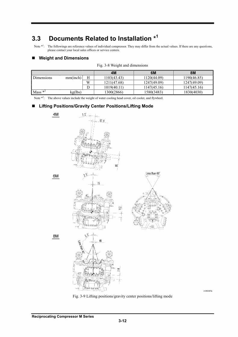
Weight and Dimensions
Fig. 3-8 Weight and dimensions
4M 6M 8M
Dimensions mm(inch) H 1103(43.43) 1120(44.09) 1190(46.85)
W 1211(47.68) 1247(49.09) 1247(49.09)
D 1019(40.11) 1147(45.16) 1147(45.16)
Mass *2 kg(lbs) 1300(2866) 1580(3483) 1830(4030)
Note *2: The above values include the weight of water cooling head cover, oil cooler, and flywheel.
Lifting Positions/Gravity Center Positions/Lifting Mode
Fig. 3-9 Lifting positions/gravity center positions/lifting mode
Reciprocating Compressor M Series
4-1
4 Operation of the Compressor
4.1 Refrigeration Oil The refrigeration oil is used for lubricating the moving parts of the compressor, preventing abnormal wear, and
cooling each section.
The following oil properties are required:
There should be an appropriate viscosity under the operating temperature and pressure conditions.
The oil should flow even under the low temperature conditions (within the range of operating
temperature for the refrigerant system).
The oil should be chemically stabilized so that it does not corrode or breakdown the components (such
as metals or rubbers).
Wax should not be separated from the oil even under low temperature.
Sludge and carbon should not be generated easily even under high temperature.
Water should not be contained in the oil.
4.1.1 Precautions for Selecting Oil Brands to be used differ depending on the types of refrigerant. For details, contact your sales office or
Mayekawa representative.
Do not use the Polyolester (POE) oil.
Do not use Hydro treated mineral oils
Naphthenic based mineral oil of ISO VG 46-68 is recommended.
The viscosity of the oil selected must stay 20 70 cSt under usage condition.
The circulation of the oil for the overall equipment must be taken into consideration. After the
refrigerant oil lubricates/cools each section of the compressor, it returns to the oil tank of the crankcase.
However, some of the oil is discharged together with the refrigerant. Most of the oil discharged from the
compressor is captured by the oil separator while some of it flows to the condenser or evaporator. As
described above, there should be sufficient ways for the oil to be returned to the correct locations.
To change the brand oil:
Changing the existing oil with other brand oil may cause an unexpected problem due to mixing of new
and old oils. Ensure sufficient oil flushing is completed before running compressor with oil approved by
Mayekawa.
If the manufacturers are different, contact both of them to confirm whether changing the oil is going to
cause problems. The same confirmation is required for changing the brand even if it is of the same
manufacturer.
There is no problem in changing the viscosity level within the same brand. As long as the change in
viscosity matches the operation conditions.
Reciprocating Compressor M Series
4-2
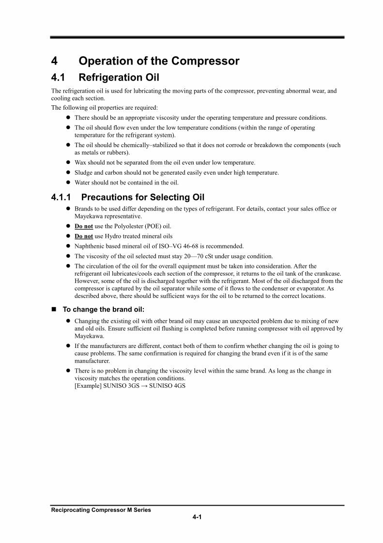
4.1.2 Initial Charging Method When charging the oil initially or changing the oil after overhaul, charge the oil from the initial supply port to fill
the oil cooler, oil filter, and oil passages with the oil.
No. Description
1 Oil supply port
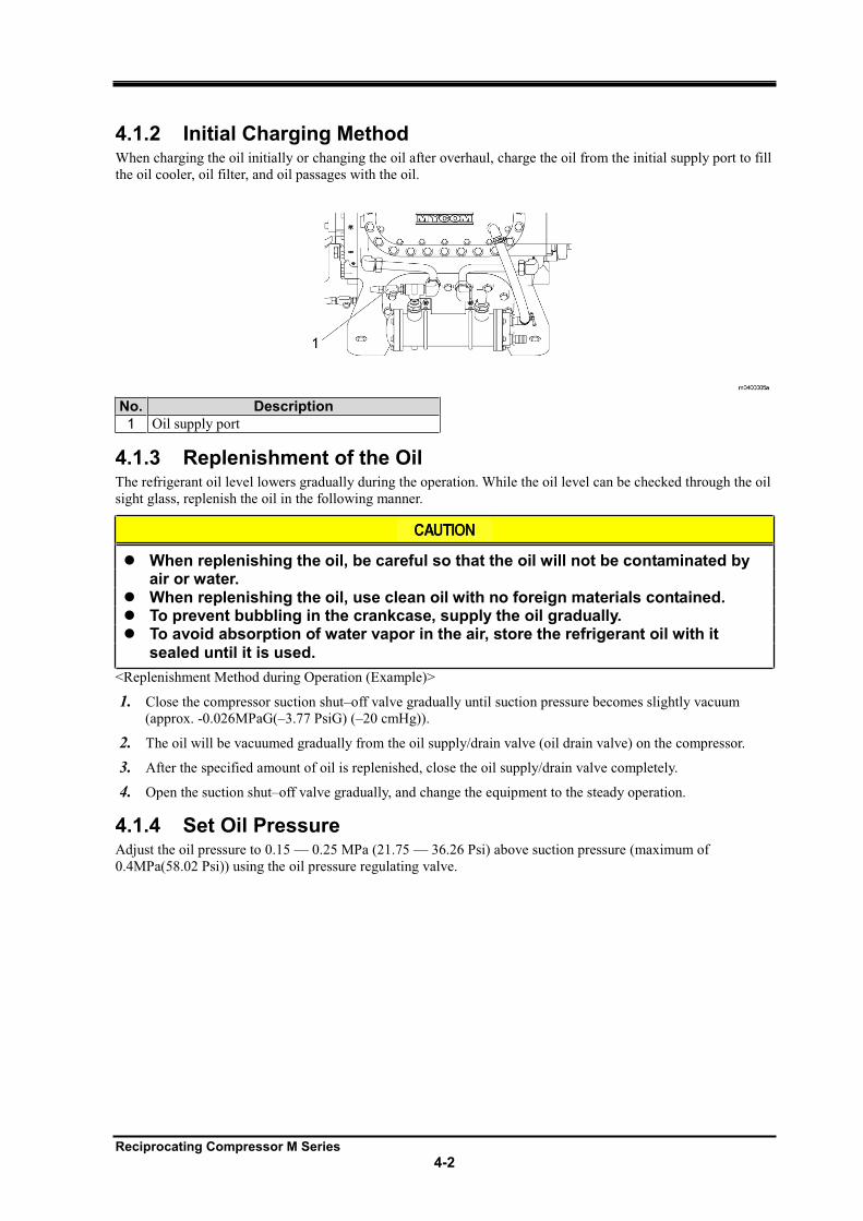
4.1.3 Replenishment of the Oil The refrigerant oil level lowers gradually during the operation. While the oil level can be checked through the oil
sight glass, replenish the oil in the following manner.
When replenishing the oil, be careful so that the oil will not be contaminated by air or water.
When replenishing the oil, use clean oil with no foreign materials contained. To prevent bubbling in the crankcase, supply the oil gradually. To avoid absorption of water vapor in the air, store the refrigerant oil with it
sealed until it is used.
<Replenishment Method during Operation (Example)>
1. Close the compressor suction shut off valve gradually until suction pressure becomes slightly vacuum
(approx. -0.026MPaG( 3.77 PsiG) ( 20 cmHg)).
2. The oil will be vacuumed gradually from the oil supply/drain valve (oil drain valve) on the compressor.
3. After the specified amount of oil is replenished, close the oil supply/drain valve completely.
4. Open the suction shut off valve gradually, and change the equipment to the steady operation.
4.1.4 Set Oil Pressure Adjust the oil pressure to 0.15 0.25 MPa (21.75 36.26 Psi) above suction pressure (maximum of
0.4MPa(58.02 Psi)) using the oil pressure regulating valve.
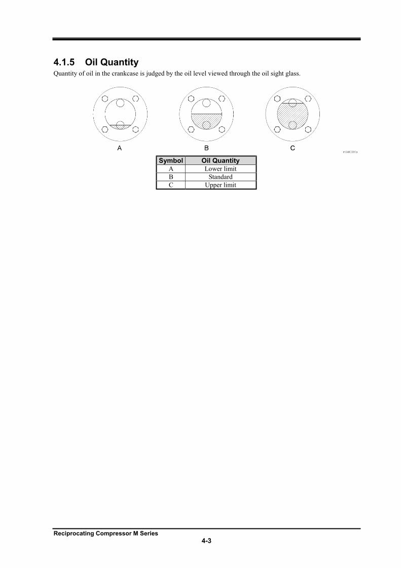
Reciprocating Compressor M Series
4-3
4.1.5 Oil Quantity Quantity of oil in the crankcase is judged by the oil level viewed through the oil sight glass.
Symbol Oil Quantity
A Lower limit
B Standard
C Upper limit
Reciprocating Compressor M Series
4-4
4.2 Initial Operation When approx. 24 hours have passed after the initial startup, foreign materials such as dust, scale, rust, and sand
in the piping can accumulate in the compressor because they flow with the refrigerant gas. Fine foreign materials
that cannot be removed by the suction filter will mix into the oil, resulting in failure or abnormal wear.
Suction of foreign materials into the compressor will continue until all foreign material has been pulled into the
compressor. The greatest amount is suctioned during the initial startup.
Presence of foreign materials can be checked by inspecting the suction filter and checking the contamination of
oil.
The oil in the crankcase can be the first sign of contamination within the refrigeration system. Therefore, if the
oil stays clear for a long period of time, it can be concluded that the inside of the equipment is also clean. If the
oil seems to be slightly blackened or turbid, the oil is contaminated with foreign materials in the equipment.
Replace the oil as soon as possible so as to prevent foreign materials from penetrating into the sliding section of
the compressor. Take sufficient care of the following two points:
Inspection/cleaning of the filter and replacement of the oil
Cleaning of the filter is required as per scheduled inspections.
Replace the oil filter elements if they are soiled. The soiled elements cannot be reused even if they
are cleaned.
Watch for any abnormal sound or temperature of the compressor.
Cleaning the oil and suction filters requires the evacuation of the refrigerant and opening of the compressor. For the evacuation of the refrigerant and assembly/disassembly of the compressor, refer to "Chapter 5. Maintenance".
Table 4-1 Reference of the oil replacement and filter inspection
Elapsed time Replacement of oil and cleaning
of oil strainer
Inspection/ replacement of
oil filter
Cleaning of suction filter
Inspection of magnet
After completion of
refrigerant charging
operation
After completion of
trial operation
100 hours after starting
operation
500 hours after starting
operation
Every 1000 hours
Note
If contamination of the refrigerant oil or clogging of the filter is found, perform oil
replacement or inspection/cleaning and replacement regardless of the above
conditions.
4.2.1 Initial Operation Method
1. Before starting operation, rotate the crankshaft (manually) or perform inching (operation of 1 2 sec)
twice to check that the oil pressure gauge operates. Check that both surfaces of the rotation side glass
lower slightly as well.
2. Operate the compressor.
Reciprocating Compressor M Series
4-5
3. Perform the initial operation according to "Table 4-1 Reference of the oil replacement and filter
inspection".
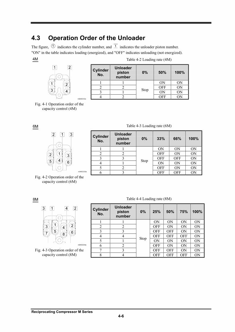
Reciprocating Compressor M Series
4-6
4.3 Operation Order of the Unloader
The figure, indicates the cylinder number, and indicates the unloader piston number.
"ON" in the table indicates loading (energized), and "OFF" indicates unloading (not energized).
Fig. 4-1 Operation order of the
capacity control (4M)
Table 4-2 Loading rate (4M)
Cylinder No.
Unloader piston
number 0% 50% 100%
1 1
Stop
ON ON
2 2 OFF ON
3 1 ON ON
4 2 OFF ON
Fig. 4-2 Operation order of the
capacity control (6M)
Table 4-3 Loading rate (6M)
Cylinder No.
Unloader piston
number 0% 33% 66% 100%
1 1
Stop
ON ON ON
2 2 OFF ON ON
3 3 OFF OFF ON
4 1 ON ON ON
5 2 OFF ON ON
6 3 OFF OFF ON
Fig. 4-3 Operation order of the
capacity control (8M)
Table 4-4 Loading rate (8M)
Cylinder No.
Unloader piston
number 0% 25% 50% 75% 100%
1 1
Stop
ON ON ON ON
2 2 OFF ON ON ON
3 3 OFF OFF ON ON
4 4 OFF OFF OFF ON
5 1 ON ON ON ON
6 2 OFF ON ON ON
7 3 OFF OFF ON ON
8 4 OFF OFF OFF ON
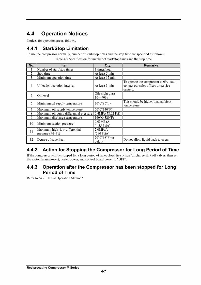
Reciprocating Compressor M Series
4-7
4.4 Operation Notices Notices for operation are as follows.
4.4.1 Start/Stop Limitation To use the compressor normally, number of start/stop times and the stop time are specified as follows.
Table 4-5 Specification for number of start/stop times and the stop time
No. Item Qty. Remarks
1 Number of start/stop times 3 times/hour
2 Stop time At least 5 min
3 Minimum operation time At least 15 min
4 Unloader operation interval At least 3 min
To operate the compressor at 0% load,
contact our sales offices or service
centers.
5 Oil level Oile sight glass
10 90%
6 Minimum oil supply temperature 30°C(86°F) This should be higher than ambient
temperature.
7 Maximum oil supply temperature 60°C(140°F)
8 Maximum oil pump differential pressure 0.4MPa(58.02 Psi)
9 Maximum discharge temperature 160°C(320°F)
10 Minimum suction pressure 0.03MPaA
(4.35 PsiA)
11 Maximum high low differential
pressure (Pd Ps)
2.0MPaA
(290 PsiA)
12 Degree of superheat 20°C(68°F) or
below Do not allow liquid back to occur.
4.4.2 Action for Stopping the Compressor for Long Period of Time If the compressor will be stopped for a long period of time, close the suction /discharge shut off valves, then set
the motor (main power), heater power, and control board power to "OFF".
4.4.3 Operation after the Compressor has been stopped for Long Period of Time
Refer to "4.2.1 Initial Operation Method".
Reciprocating Compressor M Series
5-1
5 Maintenance
5.1 Safety Precautions for Maintenance Be careful so as not to receive an electrical shock when turning on/off the power of each unit.
Before performing maintenance, turn off the motor (main power) and control power, and then perform
lockout and tagout.
Before performing maintenance, turn off the power of instruments such as a heater. Be careful that the
power does not turn on during maintenance.
Check that pressure inside the compressors is at atmospheric pressure before disassembling the machine
for inspection.
After temperature of the castings (such as head cover) is decreased to normal, perform the work.
When handling the heavy objects, take sufficient care, and handle them with at least one other person
Replace the parts with the genuine parts.
When disassembling/assembling the compressor, always use the correct tools.
All work should be performed only by qualified personnel.
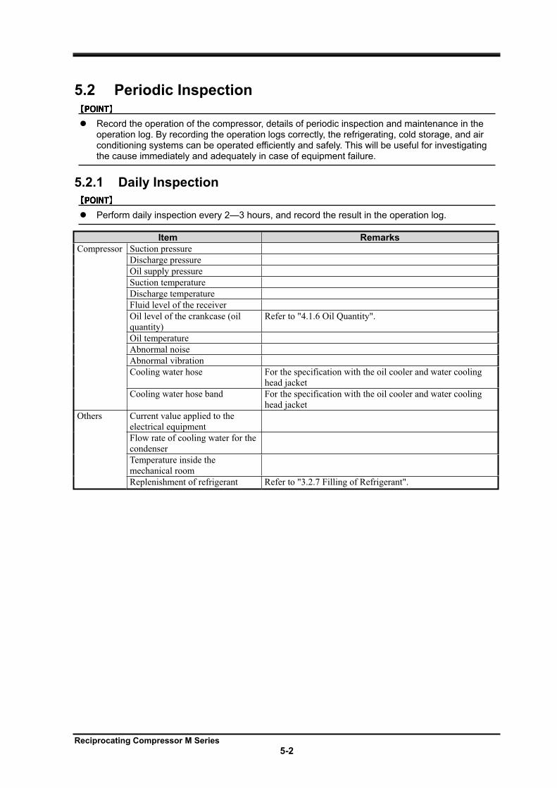
Reciprocating Compressor M Series
5-2
5.2 Periodic Inspection
Record the operation of the compressor, details of periodic inspection and maintenance in the operation log. By recording the operation logs correctly, the refrigerating, cold storage, and air conditioning systems can be operated efficiently and safely. This will be useful for investigating the cause immediately and adequately in case of equipment failure.
5.2.1 Daily Inspection
Perform daily inspection every 2—3 hours, and record the result in the operation log.
Item Remarks
Compressor Suction pressure
Discharge pressure
Oil supply pressure
Suction temperature
Discharge temperature
Fluid level of the receiver
Oil level of the crankcase (oil
quantity)
Refer to "4.1.6 Oil Quantity".
Oil temperature
Abnormal noise
Abnormal vibration
Cooling water hose For the specification with the oil cooler and water cooling
head jacket
Cooling water hose band For the specification with the oil cooler and water cooling
head jacket
Others Current value applied to the
electrical equipment
Flow rate of cooling water for the
condenser
Temperature inside the
mechanical room
Replenishment of refrigerant Refer to "3.2.7 Filling of Refrigerant".
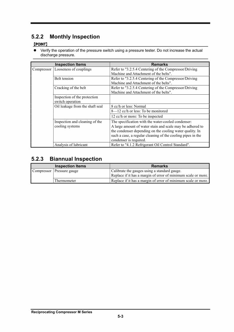
Reciprocating Compressor M Series
5-3
5.2.2 Monthly Inspection
Verify the operation of the pressure switch using a pressure tester. Do not increase the actual discharge pressure.
Inspection Items Remarks
Compressor Looseness of couplings Refer to "3.2.5.4 Centering of the Compressor/Driving
Machine and Attachment of the belts".
Belt tension Refer to "3.2.5.4 Centering of the Compressor/Driving
Machine and Attachment of the belts".
Cracking of the belt Refer to "3.2.5.4 Centering of the Compressor/Driving
Machine and Attachment of the belts".
Inspection of the protection
switch operation
Oil leakage from the shaft seal 8 cc/h or less: Normal
8—12 cc/h or less: To be monitored
12 cc/h or more: To be inspected
Inspection and cleaning of the
cooling systems
The specification with the water-cooled condenser:
A large amount of water stain and scale may be adhered to
the condenser depending on the cooling water quality. In
such a case, a regular cleaning of the cooling pipes in the
condenser is required.
Analysis of lubricant Refer to "4.1.2 Refrigerant Oil Control Standard".
5.2.3 Biannual Inspection
Inspection Items Remarks
Compressor Pressure gauge Calibrate the gauges using a standard gauge.
Replace if it has a margin of error of minimum scale or more.
Thermometer Replace if it has a margin of error of minimum scale or more.
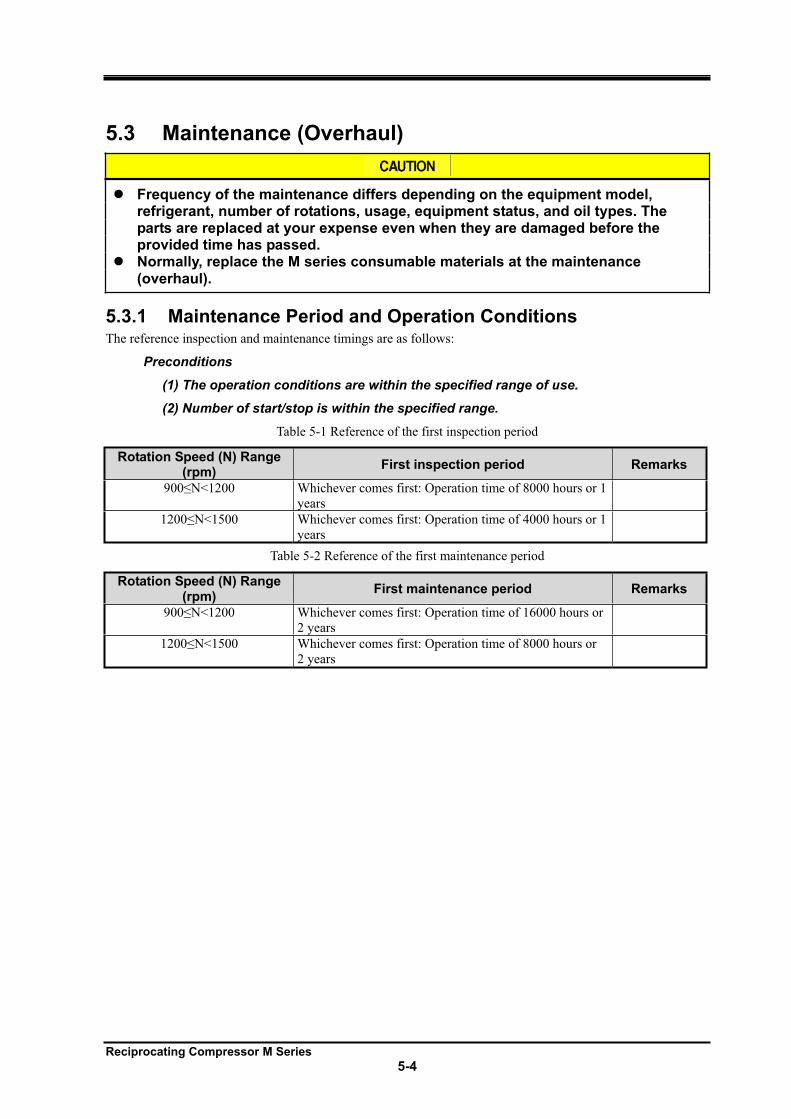
Reciprocating Compressor M Series
5-4
5.3 Maintenance (Overhaul)
Frequency of the maintenance differs depending on the equipment model, refrigerant, number of rotations, usage, equipment status, and oil types. The parts are replaced at your expense even when they are damaged before the provided time has passed. Normally, replace the M series consumable materials at the maintenance (overhaul).
5.3.1 Maintenance Period and Operation Conditions The reference inspection and maintenance timings are as follows:
Preconditions
(1) The operation conditions are within the specified range of use.
(2) Number of start/stop is within the specified range.
Table 5-1 Reference of the first inspection period
Rotation Speed (N) Range (rpm)
First inspection period Remarks
900 N<1200 Whichever comes first: Operation time of 8000 hours or 1
years
1200 N<1500 Whichever comes first: Operation time of 4000 hours or 1
years
Table 5-2 Reference of the first maintenance period
Rotation Speed (N) Range (rpm)
First maintenance period Remarks
900 N<1200 Whichever comes first: Operation time of 16000 hours or
2 years
1200 N<1500 Whichever comes first: Operation time of 8000 hours or
2 years
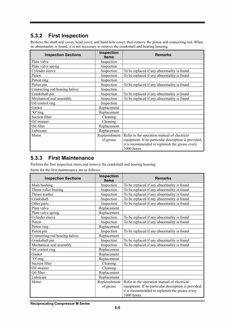
Reciprocating Compressor M Series
5-5
5.3.2 First Inspection Remove the shaft seal cover, head cover, and hand hole cover, then remove the piston and connecting rod. When
no abnormality is found, it is not necessary to remove the crankshaft and bearing housing.
Inspection Sections Inspection
ItemsRemarks
Plate valve Inspection
Plate valve spring Inspection
Cylinder sleeve Inspection To be replaced if any abnormality is found
Piston Inspection To be replaced if any abnormality is found
Piston ring Inspection
Piston pin Inspection To be replaced if any abnormality is found
Connecting rod bearing halves Inspection
Crankshaft pin Inspection To be replaced if any abnormality is found
Mechanical seal assembly Inspection To be replaced if any abnormality is found
Oil control ring Inspection
Gasket Replacement
"O"ring Replacement
Suction filter Cleaning
Oil strainer Cleaning
Oil filter Replacement
Lubricant Replacement
Motor Replenishment
of grease
Refer to the operation manual of electrical
equipment. If no particular description is provided,
it is recommended to replenish the grease every
1000 hours.
5.3.3 First Maintenance Perform the first inspection items and remove the crankshaft and bearing housing.
Items for the first maintenance are as follows.
Inspection Sections Inspection
ItemsRemarks
Main bushing Inspection To be replaced if any abnormality is found
Thrust roller bearing Inspection To be replaced if any abnormality is found
Thrust washer Inspection To be replaced if any abnormality is found
Crankshaft Inspection To be replaced if any abnormality is found
Other parts Inspection To be replaced if any abnormality is found
Plate valve Replacement
Plate valve spring Replacement
Cylinder sleeve Inspection To be replaced if any abnormality is found
Piston Inspection To be replaced if any abnormality is found
Piston ring Replacement
Piston pin Inspection To be replaced if any abnormality is found
Connecting rod bearing halves Replacement
Crankshaft pin Inspection To be replaced if any abnormality is found
Mechanical seal assembly Inspection To be replaced if any abnormality is found
Oil control ring Replacement
Gasket Replacement
"O"ring Replacement
Suction filter Cleaning
Oil strainer Cleaning
Oil filter Replacement
Lubricant Replacement
Motor Replenishment
of grease
Refer to the operation manual of electrical
equipment. If no particular description is provided,
it is recommended to replenish the grease every
1000 hours.
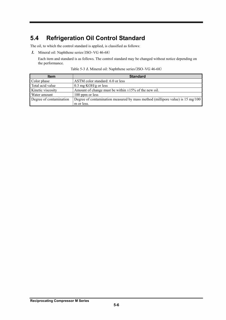
Reciprocating Compressor M Series
5-6
5.4 Refrigeration Oil Control Standard The oil, to which the control standard is applied, is classified as follows:
1. Mineral oil: Naphthene series ISO–VG 46-68
Each item and standard is as follows. The control standard may be changed without notice depending on
the performance.
Table 5-3 1. Mineral oil: Naphthene series ISO–VG 46-68
Item Standard
Color phase ASTM color standard: 6.0 or less
Total acid value 0.3 mg·KOH/g or less
Kinetic viscosity Amount of change must be within ±15% of the new oil.
Water amount 100 ppm or less
Degree of contamination Degree of contamination measured by mass method (millipore value) is 15 mg/100
m or less.
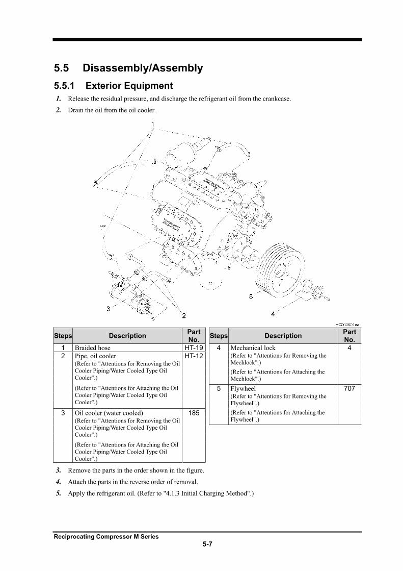
Reciprocating Compressor M Series
5-7
5.5 Disassembly/Assembly
5.5.1 Exterior Equipment
1. Release the residual pressure, and discharge the refrigerant oil from the crankcase.
2. Drain the oil from the oil cooler.
Steps Description PartNo.
Steps Description PartNo.
1 Braided hose HT-19 4 Mechanical lock 4
2 Pipe, oil cooler HT-12 (Refer to "Attentions for Removing the
Mechlock".) (Refer to "Attentions for Removing the Oil
Cooler Piping/Water Cooled Type Oil
Cooler".) (Refer to "Attentions for Attaching the
Mechlock".)
(Refer to "Attentions for Attaching the Oil
Cooler Piping/Water Cooled Type Oil
Cooler".)
5 Flywheel 707(Refer to "Attentions for Removing the
Flywheel".)
3 Oil cooler (water cooled) 185 (Refer to "Attentions for Attaching the
Flywheel".) (Refer to "Attentions for Removing the Oil
Cooler Piping/Water Cooled Type Oil
Cooler".)
(Refer to "Attentions for Attaching the Oil
Cooler Piping/Water Cooled Type Oil
Cooler".)
3. Remove the parts in the order shown in the figure.
4. Attach the parts in the reverse order of removal.
5. Apply the refrigerant oil. (Refer to "4.1.3 Initial Charging Method".)
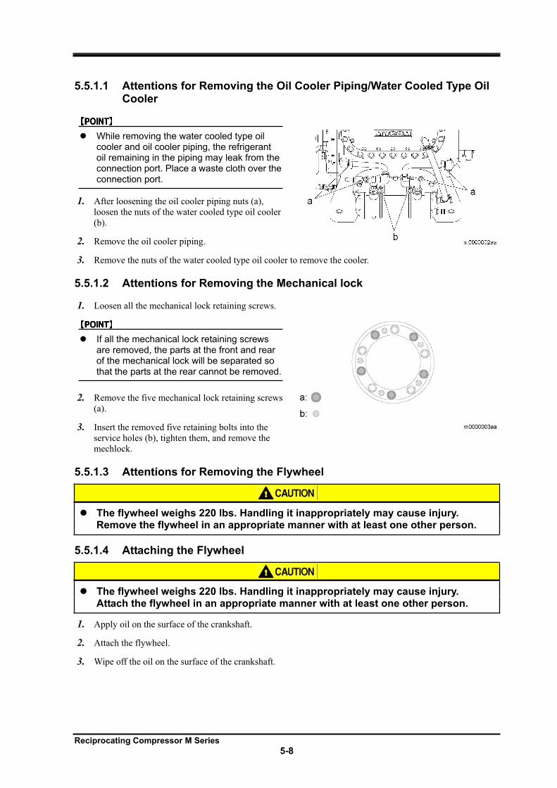
Reciprocating Compressor M Series
5-8
5.5.1.1 Attentions for Removing the Oil Cooler Piping/Water Cooled Type Oil Cooler
While removing the water cooled type oil cooler and oil cooler piping, the refrigerant oil remaining in the piping may leak from the connection port. Place a waste cloth over the connection port.
1. After loosening the oil cooler piping nuts (a),
loosen the nuts of the water cooled type oil cooler
(b).
2. Remove the oil cooler piping.
3. Remove the nuts of the water cooled type oil cooler to remove the cooler.
5.5.1.2 Attentions for Removing the Mechanical lock
1. Loosen all the mechanical lock retaining screws.
If all the mechanical lock retaining screws are removed, the parts at the front and rear of the mechanical lock will be separated so that the parts at the rear cannot be removed.
2. Remove the five mechanical lock retaining screws
(a).
3. Insert the removed five retaining bolts into the
service holes (b), tighten them, and remove the
mechlock.
5.5.1.3 Attentions for Removing the Flywheel
The flywheel weighs 220 lbs. Handling it inappropriately may cause injury. Remove the flywheel in an appropriate manner with at least one other person.
5.5.1.4 Attaching the Flywheel
The flywheel weighs 220 lbs. Handling it inappropriately may cause injury. Attach the flywheel in an appropriate manner with at least one other person.
1. Apply oil on the surface of the crankshaft.
2. Attach the flywheel.
3. Wipe off the oil on the surface of the crankshaft.
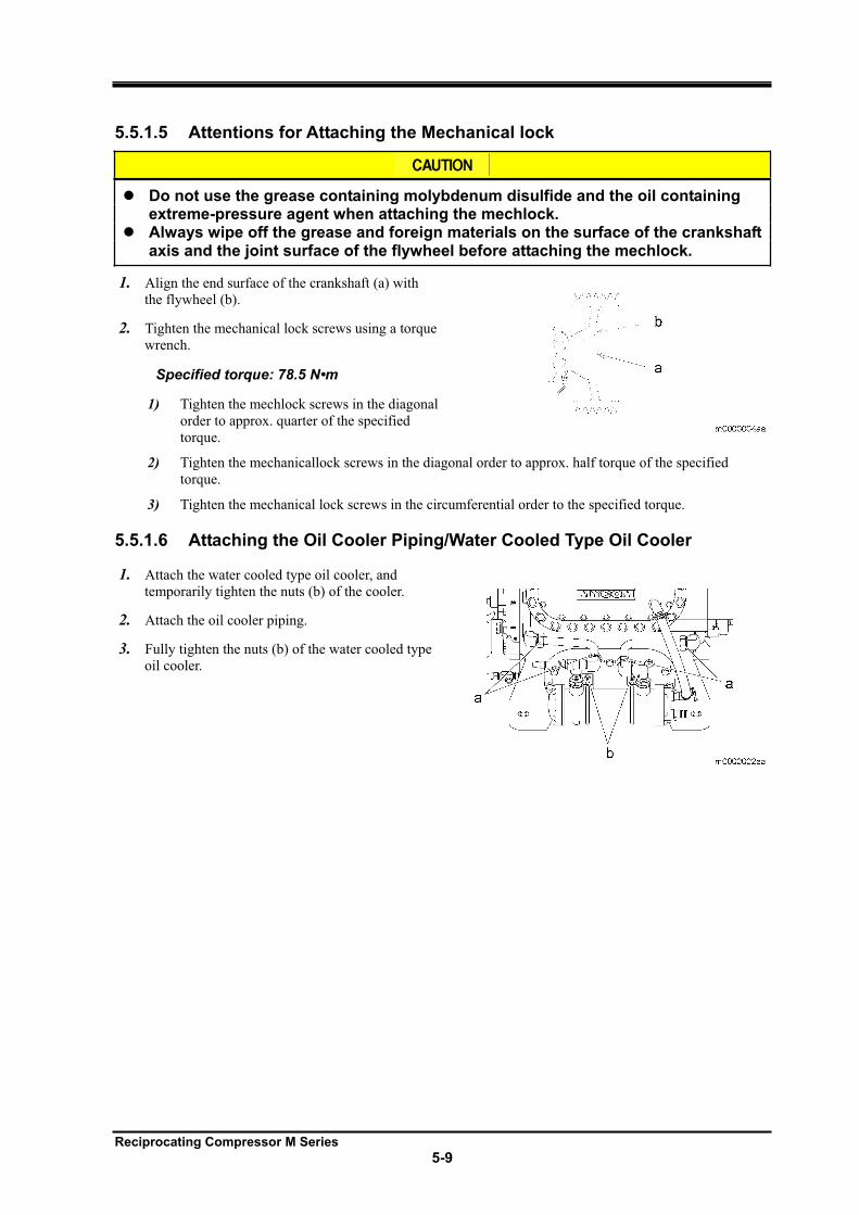
Reciprocating Compressor M Series
5-9
5.5.1.5 Attentions for Attaching the Mechanical lock
Do not use the grease containing molybdenum disulfide and the oil containing extreme-pressure agent when attaching the mechlock. Always wipe off the grease and foreign materials on the surface of the crankshaft axis and the joint surface of the flywheel before attaching the mechlock.
1. Align the end surface of the crankshaft (a) with
the flywheel (b).
2. Tighten the mechanical lock screws using a torque
wrench.
Specified torque: 78.5 N•m
1) Tighten the mechlock screws in the diagonal
order to approx. quarter of the specified
torque.
2) Tighten the mechanicallock screws in the diagonal order to approx. half torque of the specified
torque.
3) Tighten the mechanical lock screws in the circumferential order to the specified torque.
5.5.1.6 Attaching the Oil Cooler Piping/Water Cooled Type Oil Cooler
1. Attach the water cooled type oil cooler, and
temporarily tighten the nuts (b) of the cooler.
2. Attach the oil cooler piping.
3. Fully tighten the nuts (b) of the water cooled type
oil cooler.
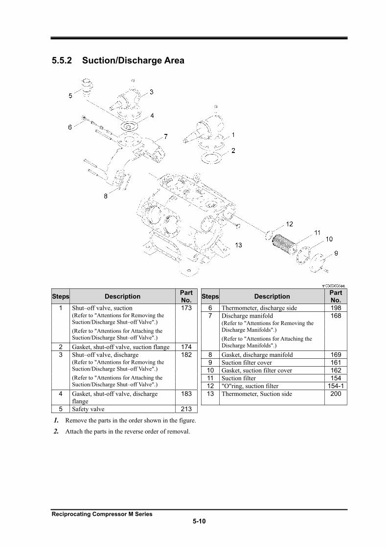
Reciprocating Compressor M Series
5-10
5.5.2 Suction/Discharge Area
Steps Description PartNo.
Steps Description PartNo.
1 Shut–off valve, suction 173 6 Thermometer, discharge side 198(Refer to "Attentions for Removing the
Suction/Discharge Shut–off Valve".) 7 Discharge manifold 168
(Refer to "Attentions for Removing the
Discharge Manifolds".) (Refer to "Attentions for Attaching the
Suction/Discharge Shut–off Valve".) (Refer to "Attentions for Attaching the
Discharge Manifolds".) 2 Gasket, shut-off valve, suction flange 174
3 Shut–off valve, discharge 182 8 Gasket, discharge manifold 169(Refer to "Attentions for Removing the
Suction/Discharge Shut–off Valve".) 9 Suction filter cover 161
10 Gasket, suction filter cover 162(Refer to "Attentions for Attaching the
Suction/Discharge Shut–off Valve".) 11 Suction filter 154
12 "O"ring, suction filter 154-1
4 Gasket, shut-off valve, discharge
flange 183 13 Thermometer, Suction side 200
5 Safety valve 213
1. Remove the parts in the order shown in the figure.
2. Attach the parts in the reverse order of removal.
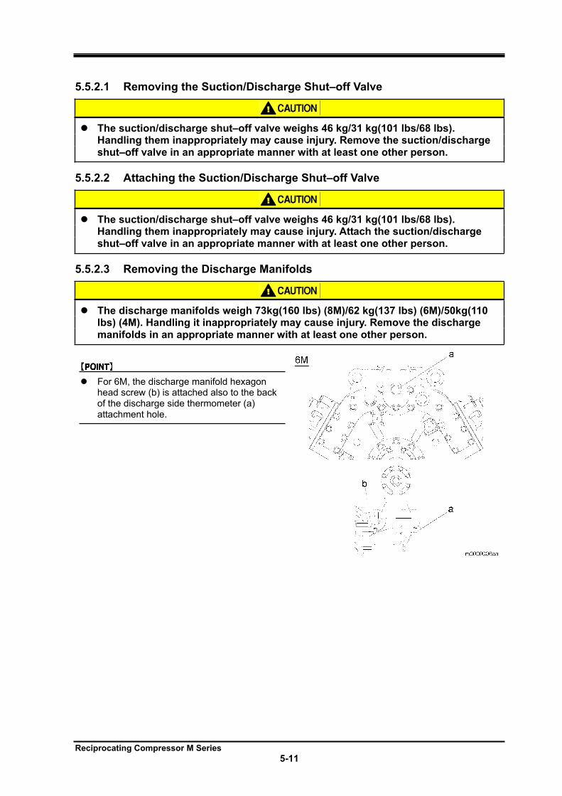
Reciprocating Compressor M Series
5-11
5.5.2.1 Removing the Suction/Discharge Shut–off Valve
The suction/discharge shut–off valve weighs 46 kg/31 kg(101 lbs/68 lbs). Handling them inappropriately may cause injury. Remove the suction/discharge shut–off valve in an appropriate manner with at least one other person.
5.5.2.2 Attaching the Suction/Discharge Shut–off Valve
The suction/discharge shut–off valve weighs 46 kg/31 kg(101 lbs/68 lbs). Handling them inappropriately may cause injury. Attach the suction/discharge shut–off valve in an appropriate manner with at least one other person.
5.5.2.3 Removing the Discharge Manifolds
The discharge manifolds weigh 73kg(160 lbs) (8M)/62 kg(137 lbs) (6M)/50kg(110 lbs) (4M). Handling it inappropriately may cause injury. Remove the discharge manifolds in an appropriate manner with at least one other person.
For 6M, the discharge manifold hexagon head screw (b) is attached also to the back of the discharge side thermometer (a) attachment hole.
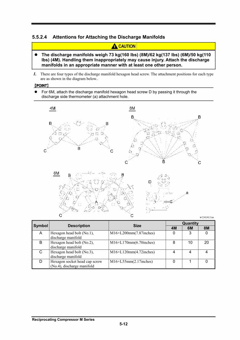
Reciprocating Compressor M Series
5-12
5.5.2.4 Attentions for Attaching the Discharge Manifolds
The discharge manifolds weigh 73 kg(160 lbs) (8M)/62 kg(137 lbs) (6M)/50 kg(110 lbs) (4M). Handling them inappropriately may cause injury. Attach the discharge manifolds in an appropriate manner with at least one other person.
1. There are four types of the discharge manifold hexagon head screw. The attachment positions for each type
are as shown in the diagram below..
For 6M, attach the discharge manifold hexagon head screw D by passing it through the discharge side thermometer (a) attachment hole.
Symbol Description Size Quantity
4M 6M 8M
A Hexagon head bolt (No.1),
discharge manifold
M16×L200mm(7.87inches) 0 3 0
B Hexagon head bolt (No.2),
discharge manifold
M16×L170mm(6.70inches) 8 10 20
C Hexagon head bolt (No.3),
discharge manifold
M16×L120mm(4.72inches) 4 4 4
D Hexagon socket head cap screw
(No.4), discharge manifold
M16×L55mm(2.17inches) 0 1 0
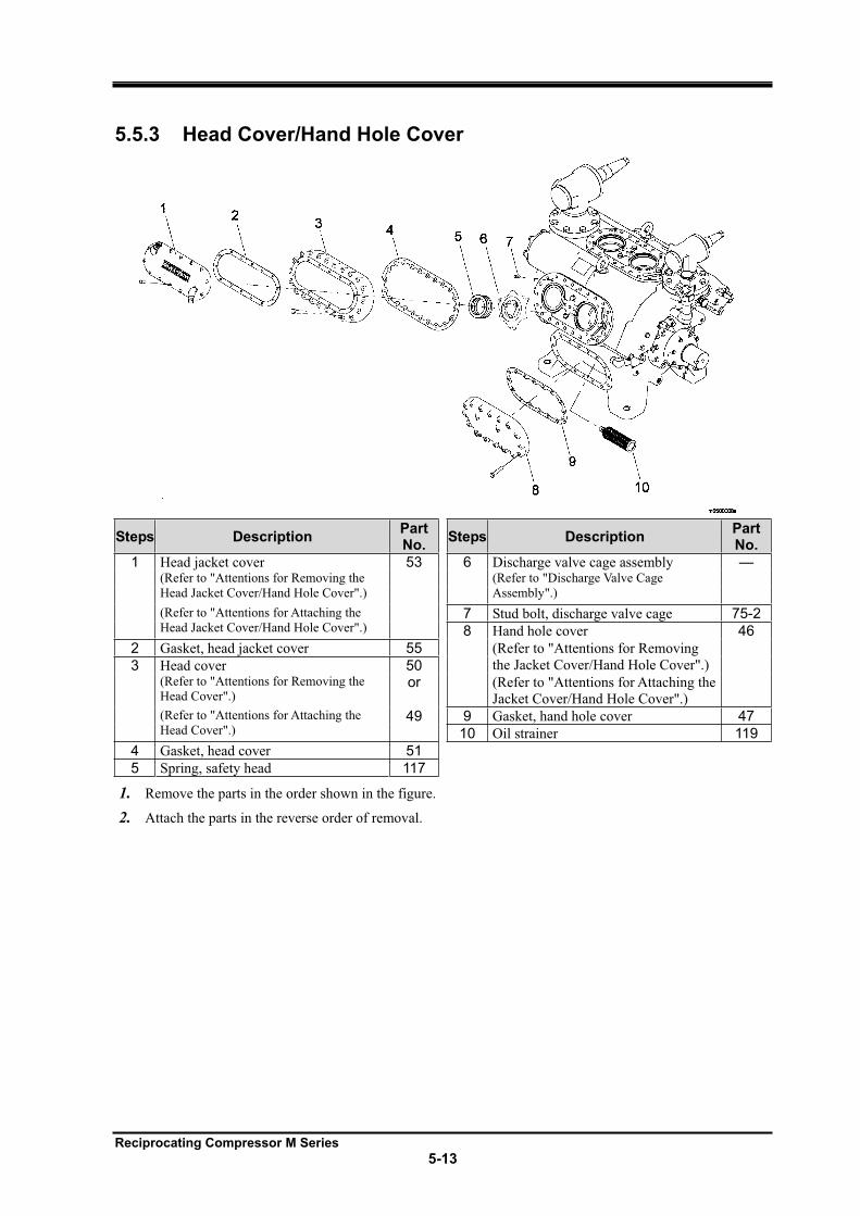
Reciprocating Compressor M Series
5-13
5.5.3 Head Cover/Hand Hole Cover
Steps Description PartNo.
Steps Description PartNo.
1 Head jacket cover 53 6 Discharge valve cage assembly —(Refer to "Attentions for Removing the
Head Jacket Cover/Hand Hole Cover".)
(Refer to "Discharge Valve Cage
Assembly".)
(Refer to "Attentions for Attaching the
Head Jacket Cover/Hand Hole Cover".) 7 Stud bolt, discharge valve cage 75-2
8 Hand hole cover 46
2 Gasket, head jacket cover 55 (Refer to "Attentions for Removing
the Jacket Cover/Hand Hole Cover".) 3 Head cover 50 (Refer to "Attentions for Removing the
Head Cover".) or (Refer to "Attentions for Attaching the
Jacket Cover/Hand Hole Cover".) (Refer to "Attentions for Attaching the
Head Cover".) 49 9 Gasket, hand hole cover 47
10 Oil strainer 119
4 Gasket, head cover 51
5 Spring, safety head 117
1. Remove the parts in the order shown in the figure.
2. Attach the parts in the reverse order of removal.
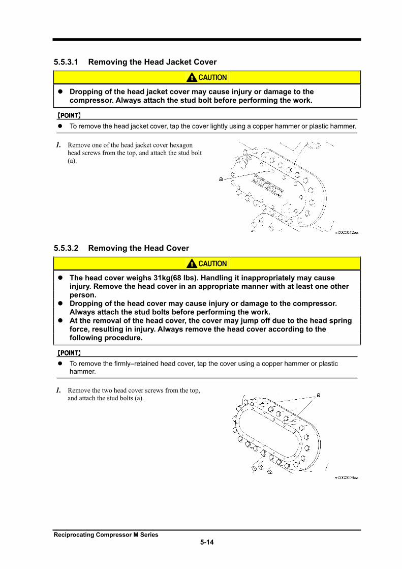
Reciprocating Compressor M Series
5-14
5.5.3.1 Removing the Head Jacket Cover
Dropping of the head jacket cover may cause injury or damage to the compressor. Always attach the stud bolt before performing the work.
To remove the head jacket cover, tap the cover lightly using a copper hammer or plastic hammer.
1. Remove one of the head jacket cover hexagon
head screws from the top, and attach the stud bolt
(a).
5.5.3.2 Removing the Head Cover
The head cover weighs 31kg(68 lbs). Handling it inappropriately may cause injury. Remove the head cover in an appropriate manner with at least one other person.Dropping of the head cover may cause injury or damage to the compressor. Always attach the stud bolts before performing the work. At the removal of the head cover, the cover may jump off due to the head spring force, resulting in injury. Always remove the head cover according to the following procedure.
To remove the firmly–retained head cover, tap the cover using a copper hammer or plastic hammer.
1. Remove the two head cover screws from the top,
and attach the stud bolts (a).
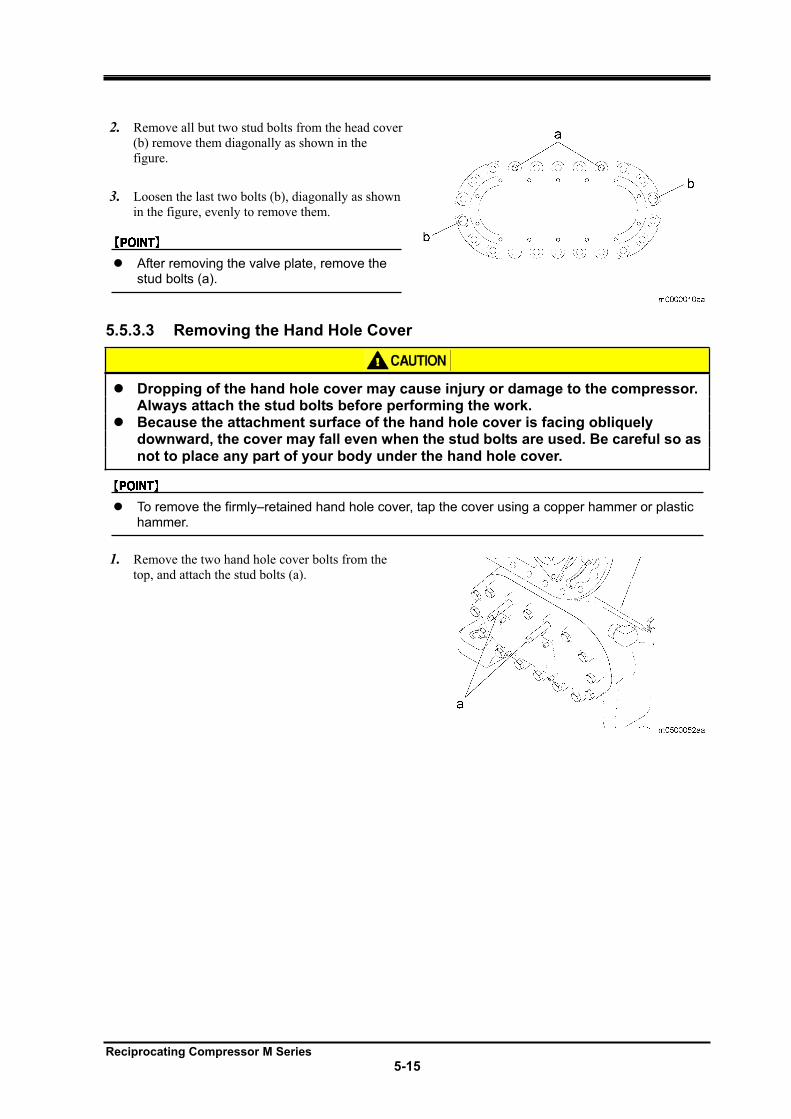
Reciprocating Compressor M Series
5-15
2. Remove all but two stud bolts from the head cover
(b) remove them diagonally as shown in the
figure.
3. Loosen the last two bolts (b), diagonally as shown
in the figure, evenly to remove them.
After removing the valve plate, remove the stud bolts (a).
5.5.3.3 Removing the Hand Hole Cover
Dropping of the hand hole cover may cause injury or damage to the compressor. Always attach the stud bolts before performing the work. Because the attachment surface of the hand hole cover is facing obliquely downward, the cover may fall even when the stud bolts are used. Be careful so as not to place any part of your body under the hand hole cover.
To remove the firmly–retained hand hole cover, tap the cover using a copper hammer or plastic hammer.
1. Remove the two hand hole cover bolts from the
top, and attach the stud bolts (a).
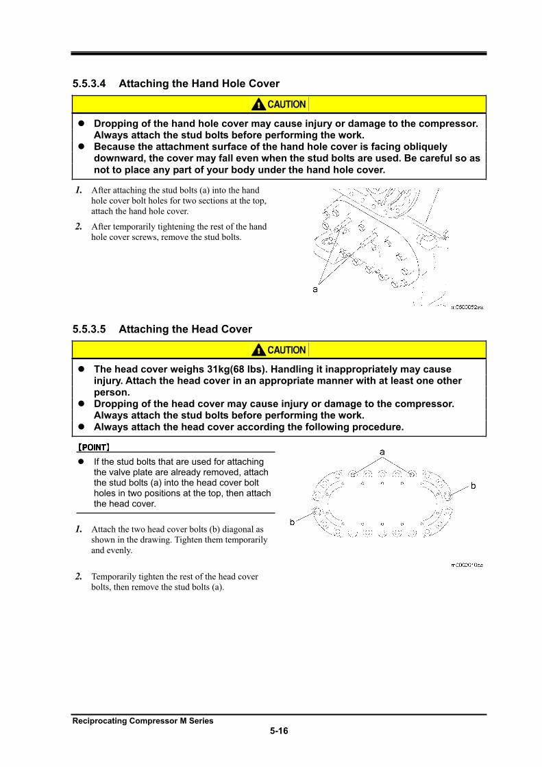
Reciprocating Compressor M Series
5-16
5.5.3.4 Attaching the Hand Hole Cover
Dropping of the hand hole cover may cause injury or damage to the compressor. Always attach the stud bolts before performing the work. Because the attachment surface of the hand hole cover is facing obliquely downward, the cover may fall even when the stud bolts are used. Be careful so as not to place any part of your body under the hand hole cover.
1. After attaching the stud bolts (a) into the hand
hole cover bolt holes for two sections at the top,
attach the hand hole cover.
2. After temporarily tightening the rest of the hand
hole cover screws, remove the stud bolts.
5.5.3.5 Attaching the Head Cover
The head cover weighs 31kg(68 lbs). Handling it inappropriately may cause injury. Attach the head cover in an appropriate manner with at least one other person.Dropping of the head cover may cause injury or damage to the compressor. Always attach the stud bolts before performing the work. Always attach the head cover according the following procedure.
If the stud bolts that are used for attaching the valve plate are already removed, attach the stud bolts (a) into the head cover bolt holes in two positions at the top, then attach the head cover.
1. Attach the two head cover bolts (b) diagonal as
shown in the drawing. Tighten them temporarily
and evenly.
2. Temporarily tighten the rest of the head cover
bolts, then remove the stud bolts (a).
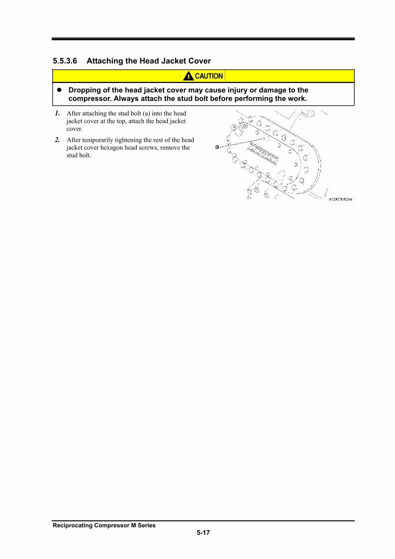
Reciprocating Compressor M Series
5-17
5.5.3.6 Attaching the Head Jacket Cover
Dropping of the head jacket cover may cause injury or damage to the compressor. Always attach the stud bolt before performing the work.
1. After attaching the stud bolt (a) into the head
jacket cover at the top, attach the head jacket
cover.
2. After temporarily tightening the rest of the head
jacket cover hexagon head screws, remove the
stud bolt.
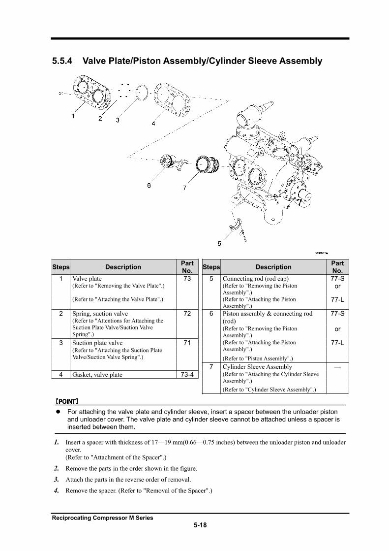
Reciprocating Compressor M Series
5-18
5.5.4 Valve Plate/Piston Assembly/Cylinder Sleeve Assembly
Steps Description PartNo.
Steps Description PartNo.
1 Valve plate 73 5 Connecting rod (rod cap) 77-S(Refer to "Removing the Valve Plate".) (Refer to "Removing the Piston
Assembly".) or
(Refer to "Attaching the Valve Plate".) (Refer to "Attaching the Piston
Assembly".) 77-L
2 Spring, suction valve 72 6 Piston assembly & connecting rod
(rod)
77-S(Refer to "Attentions for Attaching the
Suction Plate Valve/Suction Valve
Spring".)(Refer to "Removing the Piston
Assembly".) or
3 Suction plate valve 71 (Refer to "Attaching the Piston
Assembly".) 77-L
(Refer to "Attaching the Suction Plate
Valve/Suction Valve Spring".) (Refer to "Piston Assembly".)
7 Cylinder Sleeve Assembly —
4 Gasket, valve plate 73-4 (Refer to "Attaching the Cylinder Sleeve
Assembly".)
(Refer to "Cylinder Sleeve Assembly".)
For attaching the valve plate and cylinder sleeve, insert a spacer between the unloader piston and unloader cover. The valve plate and cylinder sleeve cannot be attached unless a spacer is inserted between them.
1. Insert a spacer with thickness of 17—19 mm(0.66—0.75 inches) between the unloader piston and unloader
cover.
(Refer to "Attachment of the Spacer".)
2. Remove the parts in the order shown in the figure.
3. Attach the parts in the reverse order of removal.
4. Remove the spacer. (Refer to "Removal of the Spacer".)
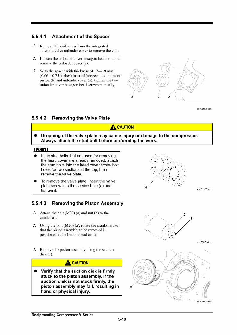
Reciprocating Compressor M Series
5-19
5.5.4.1 Attachment of the Spacer
1. Remove the coil screw from the integrated
solenoid valve unloader cover to remove the coil.
2. Loosen the unloader cover hexagon head bolt, and
remove the unloader cover (a).
3. With the spacer with thickness of 17—19 mm
(0.66—0.75 inches) inserted between the unloader
piston (b) and unloader cover (a), tighten the two
unloader cover hexagon head screws manually.
5.5.4.2 Removing the Valve Plate
Dropping of the valve plate may cause injury or damage to the compressor. Always attach the stud bolt before performing the work.
If the stud bolts that are used for removing the head cover are already removed, attach the stud bolts into the head cover screw bolt holes for two sections at the top, then remove the valve plate.
To remove the valve plate, insert the valve plate screw into the service hole (a) and tighten it.
5.5.4.3 Removing the Piston Assembly
1. Attach the bolt (M20) (a) and nut (b) to the
crankshaft.
2. Using the bolt (M20) (a), rotate the crankshaft so
that the piston assembly to be removed is
positioned at the bottom dead center.
3. Remove the piston assembly using the suction
disk (c).
Verify that the suction disk is firmly stuck to the piston assembly. If the suction disk is not stuck firmly, the piston assembly may fall, resulting in hand or physical injury.
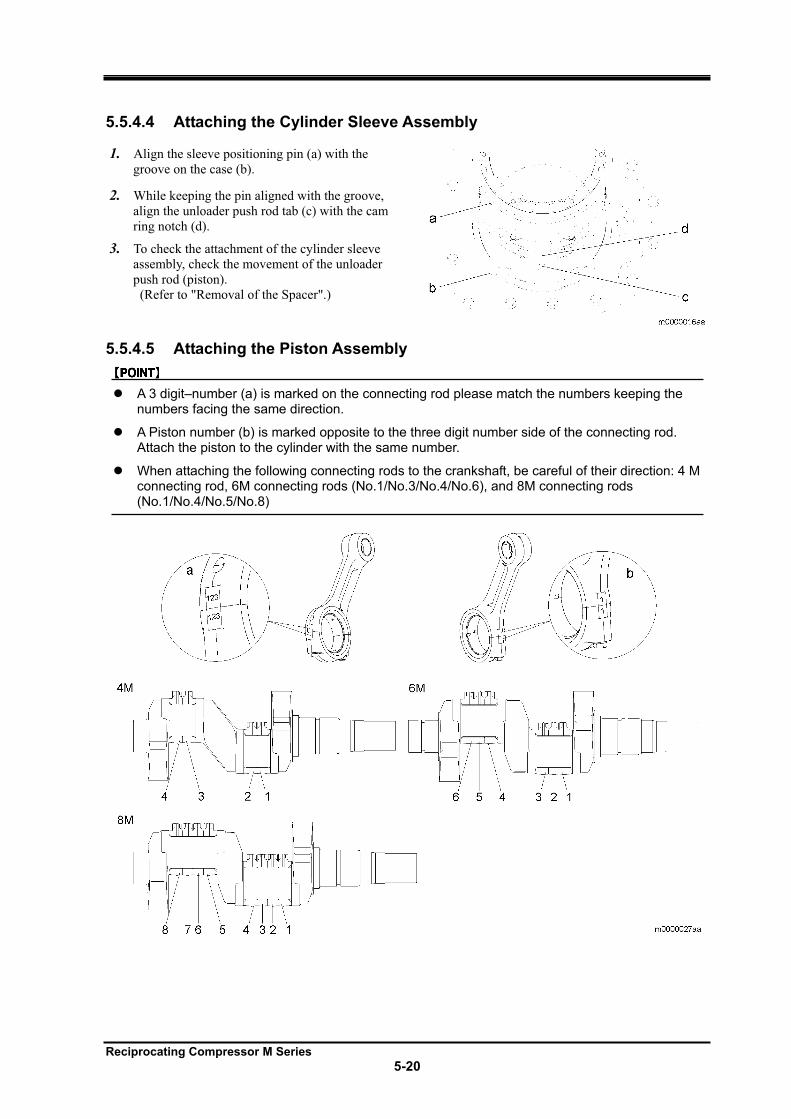
Reciprocating Compressor M Series
5-20
5.5.4.4 Attaching the Cylinder Sleeve Assembly
1. Align the sleeve positioning pin (a) with the
groove on the case (b).
2. While keeping the pin aligned with the groove,
align the unloader push rod tab (c) with the cam
ring notch (d).
3. To check the attachment of the cylinder sleeve
assembly, check the movement of the unloader
push rod (piston).
(Refer to "Removal of the Spacer".)
5.5.4.5 Attaching the Piston Assembly
A 3 digit–number (a) is marked on the connecting rod please match the numbers keeping the numbers facing the same direction.
A Piston number (b) is marked opposite to the three digit number side of the connecting rod. Attach the piston to the cylinder with the same number.
When attaching the following connecting rods to the crankshaft, be careful of their direction: 4 M connecting rod, 6M connecting rods (No.1/No.3/No.4/No.6), and 8M connecting rods (No.1/No.4/No.5/No.8)
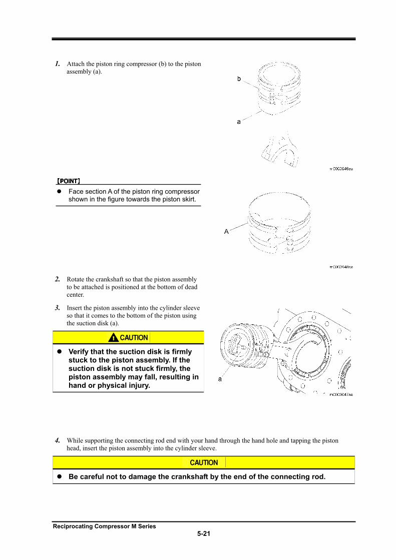
Reciprocating Compressor M Series
5-21
1. Attach the piston ring compressor (b) to the piston
assembly (a).
Face section A of the piston ring compressor shown in the figure towards the piston skirt.
2. Rotate the crankshaft so that the piston assembly
to be attached is positioned at the bottom of dead
center.
3. Insert the piston assembly into the cylinder sleeve
so that it comes to the bottom of the piston using
the suction disk (a).
Verify that the suction disk is firmly stuck to the piston assembly. If the suction disk is not stuck firmly, the piston assembly may fall, resulting in hand or physical injury.
4. While supporting the connecting rod end with your hand through the hand hole and tapping the piston
head, insert the piston assembly into the cylinder sleeve.
Be careful not to damage the crankshaft by the end of the connecting rod.
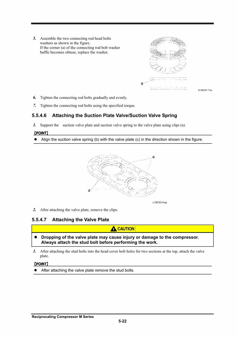
Reciprocating Compressor M Series
5-22
5. Assemble the two connecting rod head bolts
washers as shown in the figure.
If the corner (a) of the connecting rod bolt washer
baffle becomes obtuse, replace the washer.
6. Tighten the connecting rod bolts gradually and evenly.
7. Tighten the connecting rod bolts using the specified torque.
5.5.4.6 Attaching the Suction Plate Valve/Suction Valve Spring
1. Support the suction valve plate and suction valve spring to the valve plate using clips (a).
Align the suction valve spring (b) with the valve plate (c) in the direction shown in the figure.
2. After attaching the valve plate, remove the clips.
5.5.4.7 Attaching the Valve Plate
Dropping of the valve plate may cause injury or damage to the compressor. Always attach the stud bolt before performing the work.
1. After attaching the stud bolts into the head cover bolt holes for two sections at the top, attach the valve
plate.
After attaching the valve plate remove the stud bolts.
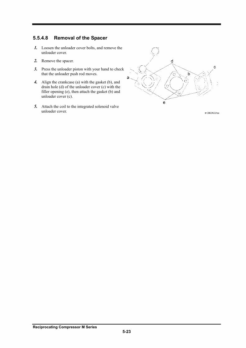
Reciprocating Compressor M Series
5-23
5.5.4.8 Removal of the Spacer
1. Loosen the unloader cover bolts, and remove the
unloader cover.
2. Remove the spacer.
3. Press the unloader piston with your hand to check
that the unloader push rod moves.
4. Align the crankcase (a) with the gasket (b), and
drain hole (d) of the unloader cover (c) with the
filler opening (e), then attach the gasket (b) and
unloader cover (c).
5. Attach the coil to the integrated solenoid valve
unloader cover.
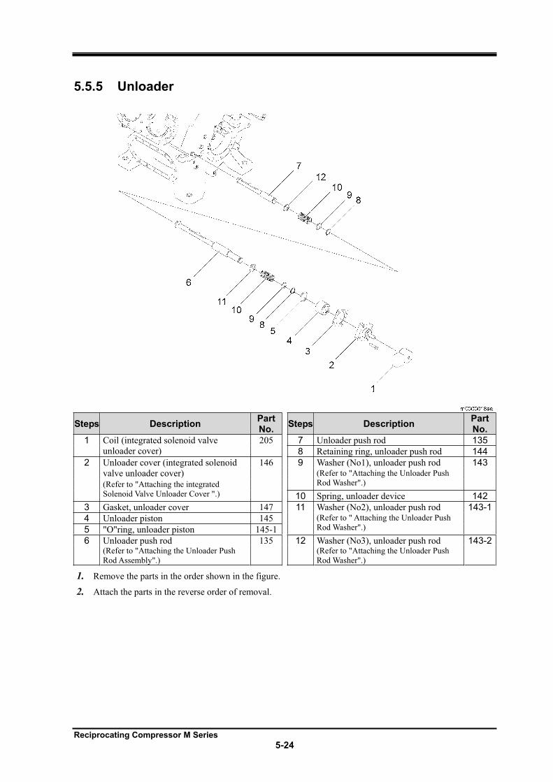
Reciprocating Compressor M Series
5-24
5.5.5 Unloader
Steps Description PartNo.
Steps Description PartNo.
1 Coil (integrated solenoid valve
unloader cover)
205 7 Unloader push rod 135
8 Retaining ring, unloader push rod 144
2 Unloader cover (integrated solenoid
valve unloader cover)
146 9 Washer (No1), unloader push rod 143(Refer to "Attaching the Unloader Push
Rod Washer".) (Refer to "Attaching the integrated
Solenoid Valve Unloader Cover ".) 10 Spring, unloader device 142
3 Gasket, unloader cover 147 11 Washer (No2), unloader push rod 143-1
4 Unloader piston 145 (Refer to " Attaching the Unloader Push
Rod Washer".) 5 "O"ring, unloader piston 145-1
6 Unloader push rod 135 12 Washer (No3), unloader push rod 143-2(Refer to "Attaching the Unloader Push
Rod Assembly".)
(Refer to "Attaching the Unloader Push
Rod Washer".)
1. Remove the parts in the order shown in the figure.
2. Attach the parts in the reverse order of removal.
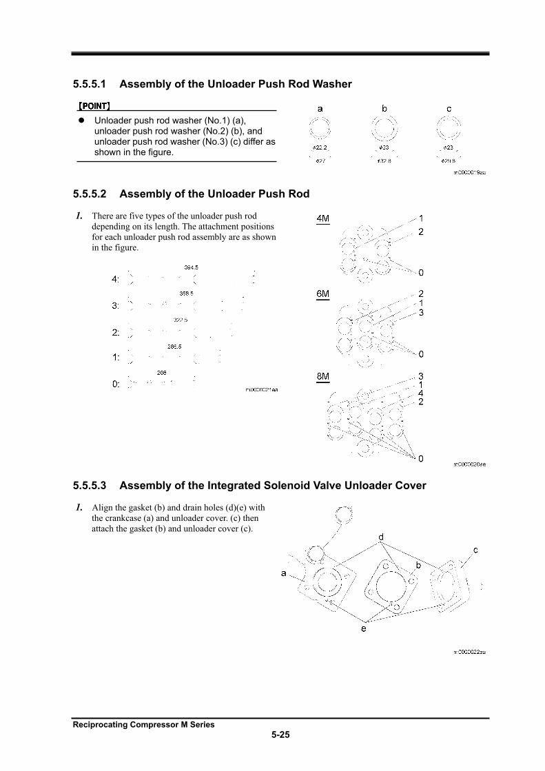
Reciprocating Compressor M Series
5-25
5.5.5.1 Assembly of the Unloader Push Rod Washer
Unloader push rod washer (No.1) (a), unloader push rod washer (No.2) (b), and unloader push rod washer (No.3) (c) differ as shown in the figure.
5.5.5.2 Assembly of the Unloader Push Rod
1. There are five types of the unloader push rod
depending on its length. The attachment positions
for each unloader push rod assembly are as shown
in the figure.
5.5.5.3 Assembly of the Integrated Solenoid Valve Unloader Cover
1. Align the gasket (b) and drain holes (d)(e) with
the crankcase (a) and unloader cover. (c) then
attach the gasket (b) and unloader cover (c).
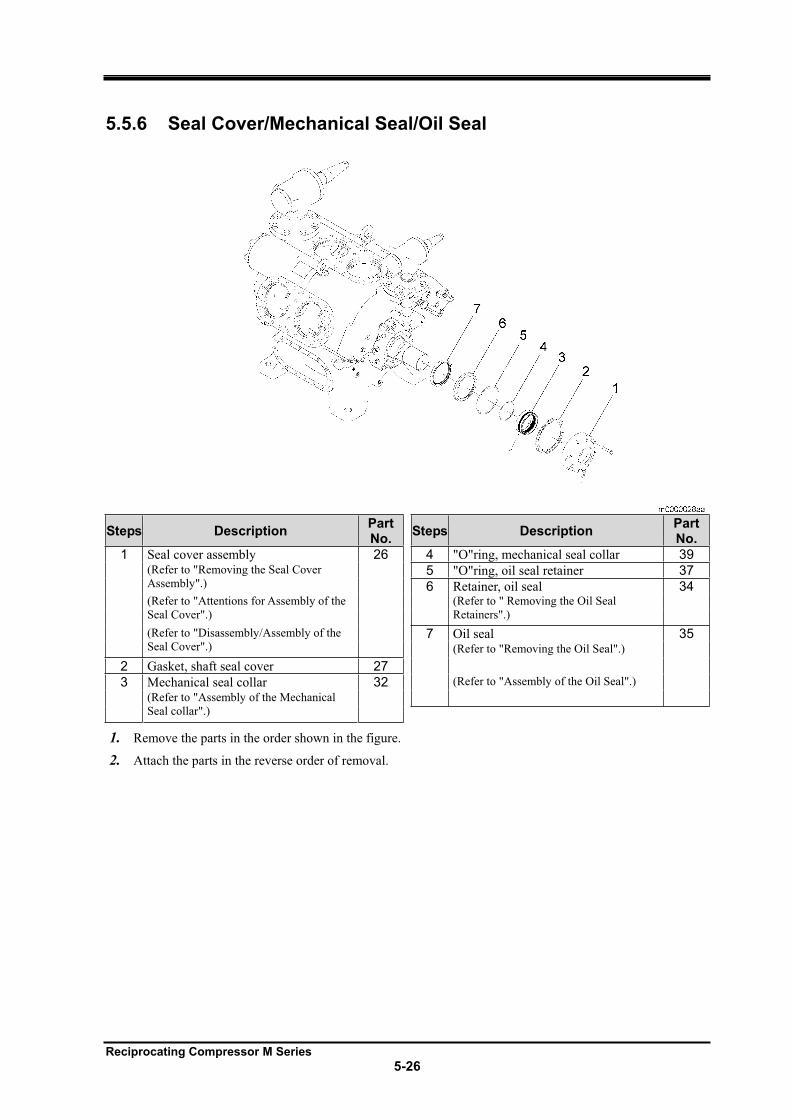
Reciprocating Compressor M Series
5-26
5.5.6 Seal Cover/Mechanical Seal/Oil Seal
Steps Description PartNo.
Steps Description PartNo.
1 Seal cover assembly 26 4 "O"ring, mechanical seal collar 39 (Refer to "Removing the Seal Cover
Assembly".) 5 "O"ring, oil seal retainer 37
6 Retainer, oil seal 34 (Refer to "Attentions for Assembly of the
Seal Cover".)
(Refer to " Removing the Oil Seal
Retainers".)
(Refer to "Disassembly/Assembly of the
Seal Cover".) 7 Oil seal 35
(Refer to "Removing the Oil Seal".)
2 Gasket, shaft seal cover 27
3 Mechanical seal collar 32 (Refer to "Assembly of the Oil Seal".)
(Refer to "Assembly of the Mechanical
Seal collar".)
1. Remove the parts in the order shown in the figure.
2. Attach the parts in the reverse order of removal.
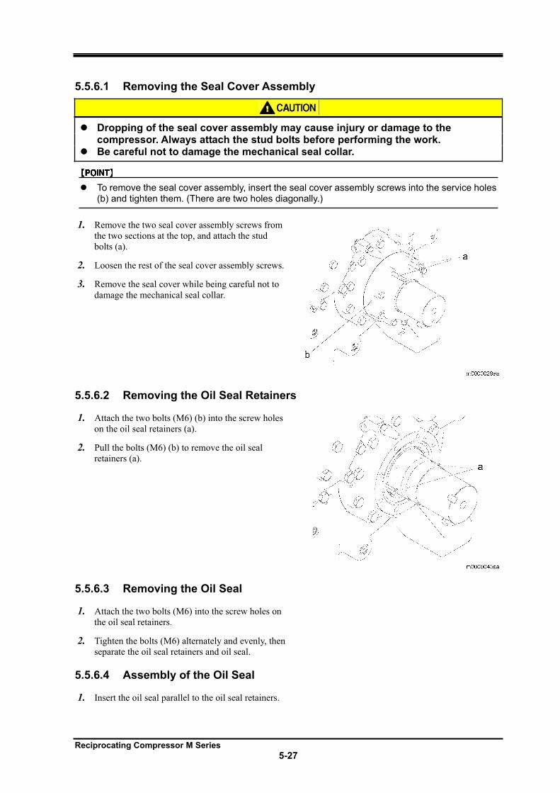
Reciprocating Compressor M Series
5-27
5.5.6.1 Removing the Seal Cover Assembly
Dropping of the seal cover assembly may cause injury or damage to the compressor. Always attach the stud bolts before performing the work. Be careful not to damage the mechanical seal collar.
To remove the seal cover assembly, insert the seal cover assembly screws into the service holes (b) and tighten them. (There are two holes diagonally.)
1. Remove the two seal cover assembly screws from
the two sections at the top, and attach the stud
bolts (a).
2. Loosen the rest of the seal cover assembly screws.
3. Remove the seal cover while being careful not to
damage the mechanical seal collar.
5.5.6.2 Removing the Oil Seal Retainers
1. Attach the two bolts (M6) (b) into the screw holes
on the oil seal retainers (a).
2. Pull the bolts (M6) (b) to remove the oil seal
retainers (a).
5.5.6.3 Removing the Oil Seal
1. Attach the two bolts (M6) into the screw holes on
the oil seal retainers.
2. Tighten the bolts (M6) alternately and evenly, then
separate the oil seal retainers and oil seal.
5.5.6.4 Assembly of the Oil Seal
1. Insert the oil seal parallel to the oil seal retainers.
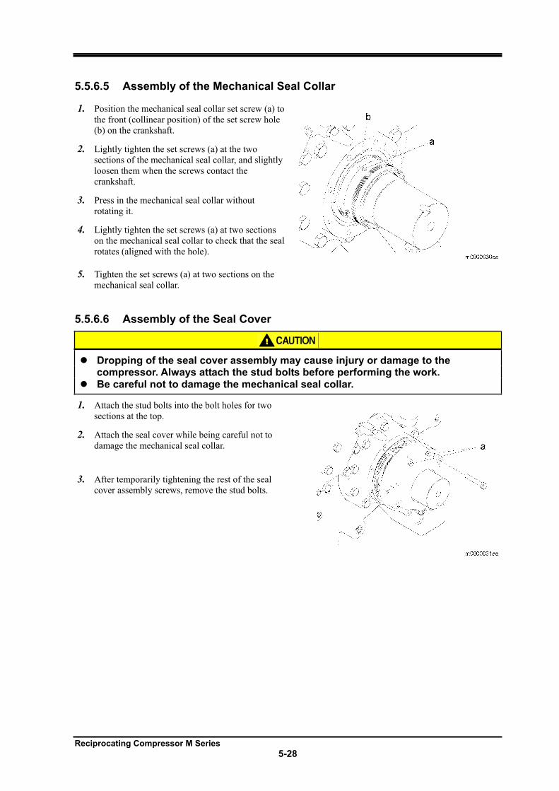
Reciprocating Compressor M Series
5-28
5.5.6.5 Assembly of the Mechanical Seal Collar
1. Position the mechanical seal collar set screw (a) to
the front (collinear position) of the set screw hole
(b) on the crankshaft.
2. Lightly tighten the set screws (a) at the two
sections of the mechanical seal collar, and slightly
loosen them when the screws contact the
crankshaft.
3. Press in the mechanical seal collar without
rotating it.
4. Lightly tighten the set screws (a) at two sections
on the mechanical seal collar to check that the seal
rotates (aligned with the hole).
5. Tighten the set screws (a) at two sections on the
mechanical seal collar.
5.5.6.6 Assembly of the Seal Cover
Dropping of the seal cover assembly may cause injury or damage to the compressor. Always attach the stud bolts before performing the work. Be careful not to damage the mechanical seal collar.
1. Attach the stud bolts into the bolt holes for two
sections at the top.
2. Attach the seal cover while being careful not to
damage the mechanical seal collar.
3. After temporarily tightening the rest of the seal
cover assembly screws, remove the stud bolts.
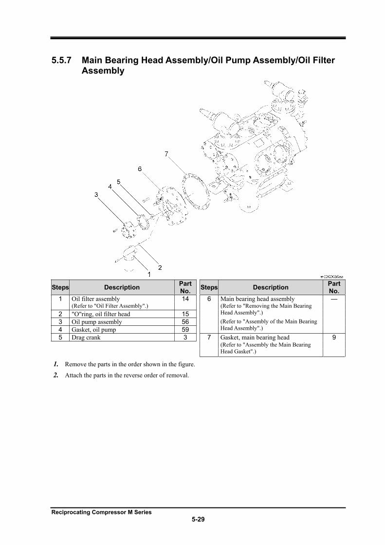
Reciprocating Compressor M Series
5-29
5.5.7 Main Bearing Head Assembly/Oil Pump Assembly/Oil Filter Assembly
Steps Description PartNo.
Steps Description PartNo.
1 Oil filter assembly 14 6 Main bearing head assembly —(Refer to "Oil Filter Assembly".) (Refer to "Removing the Main Bearing
Head Assembly".) 2 "O"ring, oil filter head 15
3 Oil pump assembly 56 (Refer to "Assembly of the Main Bearing
Head Assembly".) 4 Gasket, oil pump 59
5 Drag crank 3 7 Gasket, main bearing head 9(Refer to "Assembly the Main Bearing
Head Gasket".)
1. Remove the parts in the order shown in the figure.
2. Attach the parts in the reverse order of removal.
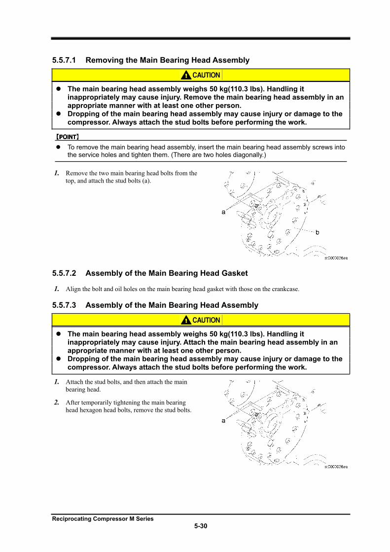
Reciprocating Compressor M Series
5-30
5.5.7.1 Removing the Main Bearing Head Assembly
The main bearing head assembly weighs 50 kg(110.3 lbs). Handling it inappropriately may cause injury. Remove the main bearing head assembly in an appropriate manner with at least one other person. Dropping of the main bearing head assembly may cause injury or damage to the compressor. Always attach the stud bolts before performing the work.
To remove the main bearing head assembly, insert the main bearing head assembly screws into the service holes and tighten them. (There are two holes diagonally.)
1. Remove the two main bearing head bolts from the
top, and attach the stud bolts (a).
5.5.7.2 Assembly of the Main Bearing Head Gasket
1. Align the bolt and oil holes on the main bearing head gasket with those on the crankcase.
5.5.7.3 Assembly of the Main Bearing Head Assembly
The main bearing head assembly weighs 50 kg(110.3 lbs). Handling it inappropriately may cause injury. Attach the main bearing head assembly in an appropriate manner with at least one other person. Dropping of the main bearing head assembly may cause injury or damage to the compressor. Always attach the stud bolts before performing the work.
1. Attach the stud bolts, and then attach the main
bearing head.
2. After temporarily tightening the main bearing
head hexagon head bolts, remove the stud bolts.
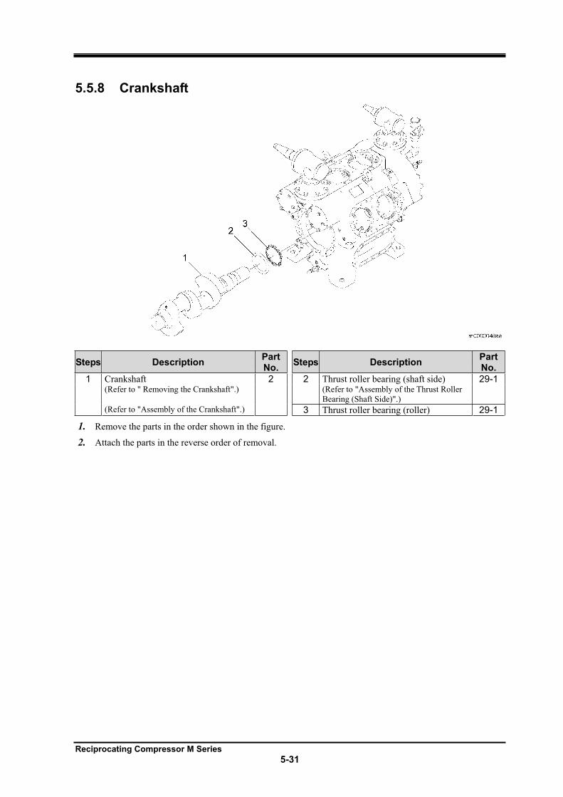
Reciprocating Compressor M Series
5-31
5.5.8 Crankshaft
Steps Description PartNo.
Steps Description PartNo.
1 Crankshaft 2 2 Thrust roller bearing (shaft side) 29-1(Refer to " Removing the Crankshaft".) (Refer to "Assembly of the Thrust Roller
Bearing (Shaft Side)".)
(Refer to "Assembly of the Crankshaft".) 3 Thrust roller bearing (roller) 29-1
1. Remove the parts in the order shown in the figure.
2. Attach the parts in the reverse order of removal.
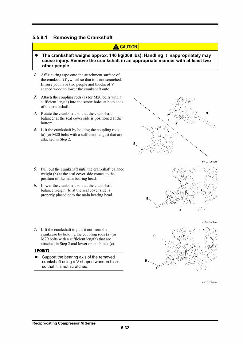
Reciprocating Compressor M Series
5-32
5.5.8.1 Removing the Crankshaft
The crankshaft weighs approx. 140 kg(308 lbs). Handling it inappropriately may cause injury. Remove the crankshaft in an appropriate manner with at least two other people.
1. Affix curing tape onto the attachment surface of
the crankshaft flywheel so that it is not scratched.
Ensure you have two people and blocks of V
shaped wood to lower the crankshaft onto.
2. Attach the coupling rods (a) (or M20 bolts with a
sufficient length) into the screw holes at both ends
of the crankshaft.
3. Rotate the crankshaft so that the crankshaft
balancer at the seal cover side is positioned at the
bottom.
4. Lift the crankshaft by holding the coupling rods
(a) (or M20 bolts with a sufficient length) that are
attached in Step 2.
5. Pull out the crankshaft until the crankshaft balance
weight (b) at the seal cover side comes to the
position of the main bearing head.
6. Lower the crankshaft so that the crankshaft
balance weight (b) at the seal cover side is
properly placed onto the main bearing head.
7. Lift the crankshaft to pull it out from the
crankcase by holding the coupling rods (a) (or
M20 bolts with a sufficient length) that are
attached in Step 2 and lower onto a block (c).
Support the bearing axis of the removed crankshaft using a V-shaped wooden block so that it is not scratched.
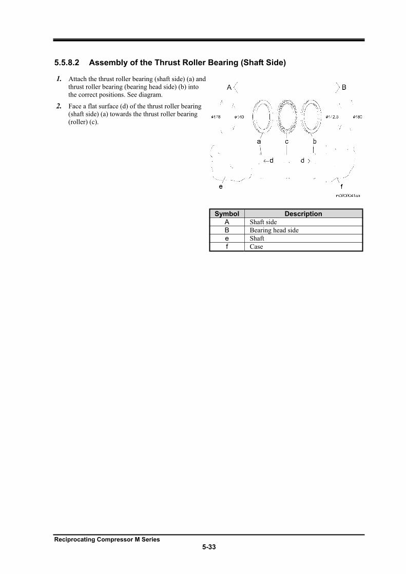
Reciprocating Compressor M Series
5-33
5.5.8.2 Assembly of the Thrust Roller Bearing (Shaft Side)
1. Attach the thrust roller bearing (shaft side) (a) and
thrust roller bearing (bearing head side) (b) into
the correct positions. See diagram.
2. Face a flat surface (d) of the thrust roller bearing
(shaft side) (a) towards the thrust roller bearing
(roller) (c).
Symbol Description
A Shaft side
B Bearing head side
e Shaft
f Case
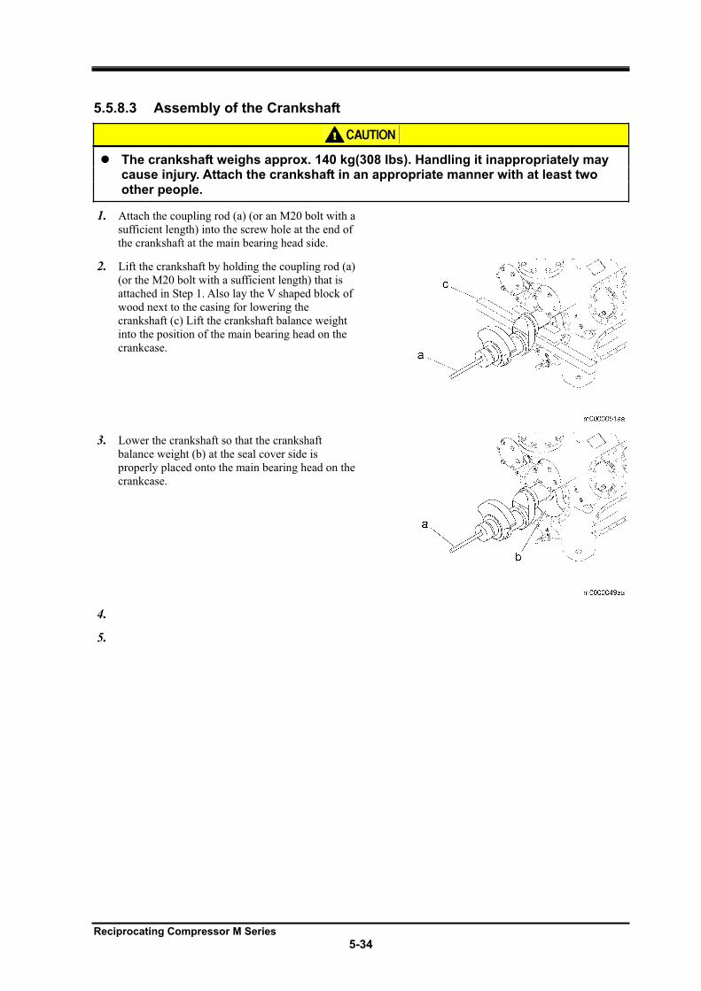
Reciprocating Compressor M Series
5-34
5.5.8.3 Assembly of the Crankshaft
The crankshaft weighs approx. 140 kg(308 lbs). Handling it inappropriately may cause injury. Attach the crankshaft in an appropriate manner with at least two other people.
1. Attach the coupling rod (a) (or an M20 bolt with a
sufficient length) into the screw hole at the end of
the crankshaft at the main bearing head side.
2. Lift the crankshaft by holding the coupling rod (a)
(or the M20 bolt with a sufficient length) that is
attached in Step 1. Also lay the V shaped block of
wood next to the casing for lowering the
crankshaft (c) Lift the crankshaft balance weight
into the position of the main bearing head on the
crankcase.
3. Lower the crankshaft so that the crankshaft
balance weight (b) at the seal cover side is
properly placed onto the main bearing head on the
crankcase.
4.
5.
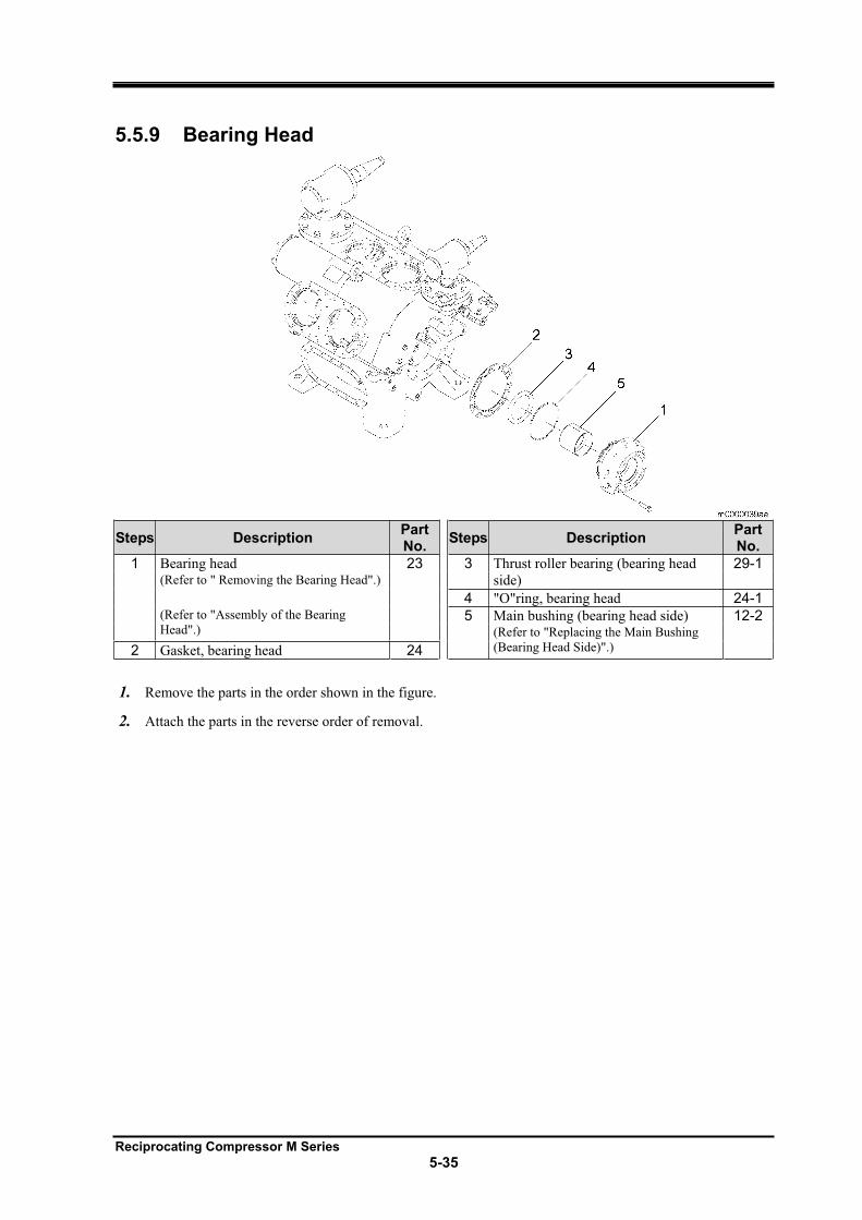
Reciprocating Compressor M Series
5-35
5.5.9 Bearing Head
Steps Description PartNo.
Steps Description PartNo.
1 Bearing head 23 3 Thrust roller bearing (bearing head
side)
29-1(Refer to " Removing the Bearing Head".)
4 "O"ring, bearing head 24-1(Refer to "Assembly of the Bearing
Head".) 5 Main bushing (bearing head side) 12-2
(Refer to "Replacing the Main Bushing
(Bearing Head Side)".) 2 Gasket, bearing head 24
1. Remove the parts in the order shown in the figure.
2. Attach the parts in the reverse order of removal.
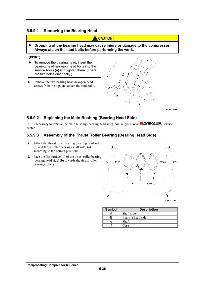
Reciprocating Compressor M Series
5-36
5.5.9.1 Removing the Bearing Head
Dropping of the bearing head may cause injury or damage to the compressor. Always attach the stud bolts before performing the work.
To remove the bearing head, insert the bearing head hexagon head bolts into the service holes (a) and tighten them. (There are two holes diagonally.)
1. Remove the two bearing head hexagon head
screws from the top, and attach the stud bolts.
5.5.9.2 Replacing the Main Bushing (Bearing Head Side)
If it is necessary to remove the main bushing (bearing head side), contact your local service
center.
5.5.9.3 Assembly of the Thrust Roller Bearing (Bearing Head Side)
1. Attach the thrust roller bearing (bearing head side)
(b) and thrust roller bearing (shaft side) (a)
according to the correct positions.
2. Face the flat surface (d) of the thrust roller bearing
(bearing head side) (b) towards the thrust roller
bearing (roller) (c).
Symbol Description
A Shaft side
B Bearing head side
e Shaft
f Case
Reciprocating Compressor M Series
5-37
5.5.9.4 Assembly of the Bearing Head
Dropping of the bearing head may cause injury or damage to the compressor. Always attach the stud bolts before performing the work.
1. After attaching the stud bolts into the bearing head
for two sections at the top, attach the bearing
head.
2. After temporarily tightening the rest of the bearing
head hexagon head screws, remove the stud bolts.
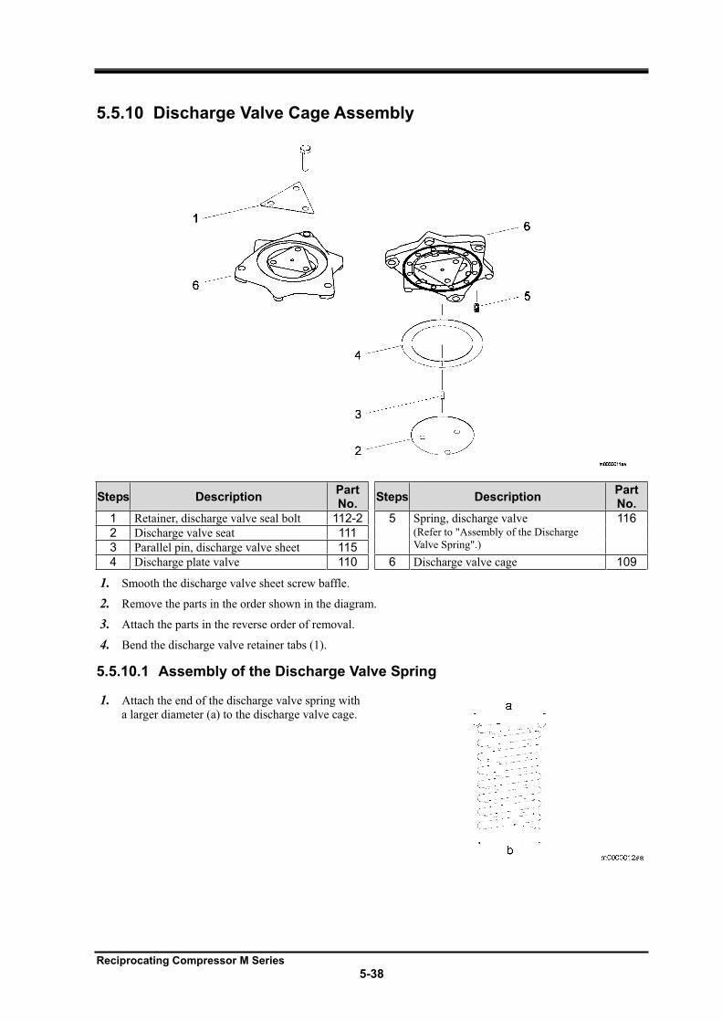
Reciprocating Compressor M Series
5-38
5.5.10 Discharge Valve Cage Assembly
Steps Description PartNo.
Steps Description PartNo.
1 Retainer, discharge valve seal bolt 112-2 5 Spring, discharge valve 116
2 Discharge valve seat 111 (Refer to "Assembly of the Discharge
Valve Spring".) 3 Parallel pin, discharge valve sheet 115
4 Discharge plate valve 110 6 Discharge valve cage 109
1. Smooth the discharge valve sheet screw baffle.
2. Remove the parts in the order shown in the diagram.
3. Attach the parts in the reverse order of removal.
4. Bend the discharge valve retainer tabs (1).
5.5.10.1 Assembly of the Discharge Valve Spring
1. Attach the end of the discharge valve spring with
a larger diameter (a) to the discharge valve cage.
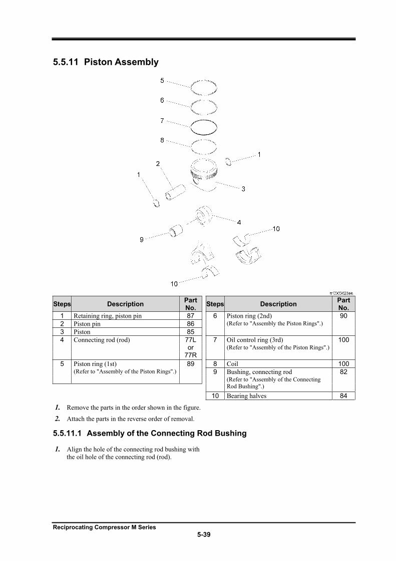
Reciprocating Compressor M Series
5-39
5.5.11 Piston Assembly
Steps Description PartNo.
Steps Description PartNo.
1 Retaining ring, piston pin 87 6 Piston ring (2nd) 90
2 Piston pin 86 (Refer to "Assembly the Piston Rings".)
3 Piston 85
4 Connecting rod (rod) 77Lor
77R
7 Oil control ring (3rd) 100(Refer to "Assembly of the Piston Rings".)
5 Piston ring (1st) 89 8 Coil 100(Refer to "Assembly of the Piston Rings".) 9 Bushing, connecting rod 82
(Refer to "Assembly of the Connecting
Rod Bushing".)
10 Bearing halves 84
1. Remove the parts in the order shown in the figure.
2. Attach the parts in the reverse order of removal.
5.5.11.1 Assembly of the Connecting Rod Bushing
1. Align the hole of the connecting rod bushing with
the oil hole of the connecting rod (rod).
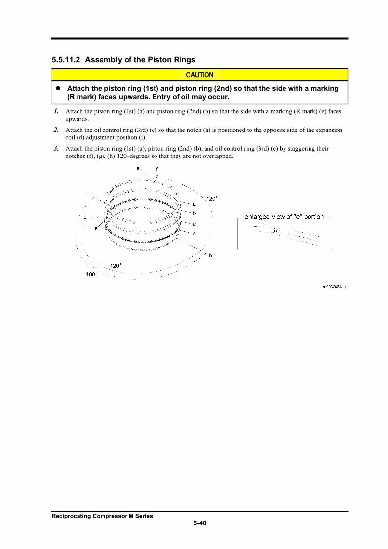
Reciprocating Compressor M Series
5-40
5.5.11.2 Assembly of the Piston Rings
Attach the piston ring (1st) and piston ring (2nd) so that the side with a marking (R mark) faces upwards. Entry of oil may occur.
1. Attach the piston ring (1st) (a) and piston ring (2nd) (b) so that the side with a marking (R mark) (e) faces
upwards.
2. Attach the oil control ring (3rd) (c) so that the notch (h) is positioned to the opposite side of the expansion
coil (d) adjustment position (i).
3. Attach the piston ring (1st) (a), piston ring (2nd) (b), and oil control ring (3rd) (c) by staggering their
notches (f), (g), (h) 120–degrees so that they are not overlapped.
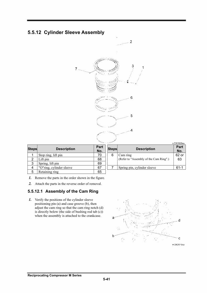
Reciprocating Compressor M Series
5-41
5.5.12 Cylinder Sleeve Assembly
Steps Description PartNo.
Steps Description PartNo.
1 Stop ring, lift pin 70 6 Cam ring 62 or
2 Lift pin 68 (Refer to "Assembly of the Cam Ring".) 63
3 Spring, lift pin 69
4 "O"ring, cylinder sleeve 67 7 Spring pin, cylinder sleeve 61-1
5 Retaining ring 65
1. Remove the parts in the order shown in the figure.
2. Attach the parts in the reverse order of removal.
5.5.12.1 Assembly of the Cam Ring
1. Verify the positions of the cylinder sleeve
positioning pin (a) and case groove (b), then
adjust the cam ring so that the cam ring notch (d)
is directly below (the side of bushing rod tab (c))
when the assembly is attached to the crankcase.
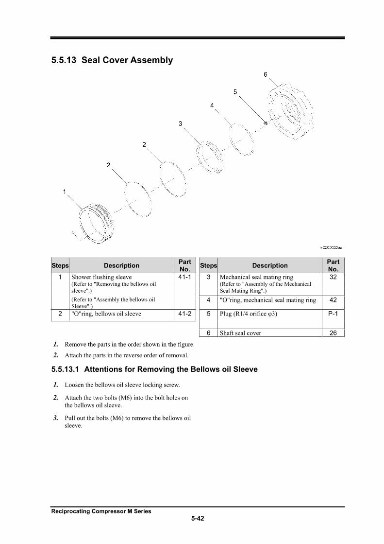
Reciprocating Compressor M Series
5-42
5.5.13 Seal Cover Assembly
Steps Description PartNo.
Steps Description PartNo.
1 Shower flushing sleeve 41-1 3 Mechanical seal mating ring 32 (Refer to "Removing the bellows oil
sleeve".)
(Refer to "Assembly of the Mechanical
Seal Mating Ring".)
(Refer to "Assembly the bellows oil
Sleeve".) 4 "O"ring, mechanical seal mating ring 42
2 "O"ring, bellows oil sleeve 41-2 5 Plug (R1/4 orifice 3) P-1
6 Shaft seal cover 26
1. Remove the parts in the order shown in the figure.
2. Attach the parts in the reverse order of removal.
5.5.13.1 Attentions for Removing the Bellows oil Sleeve
1. Loosen the bellows oil sleeve locking screw.
2. Attach the two bolts (M6) into the bolt holes on
the bellows oil sleeve.
3. Pull out the bolts (M6) to remove the bellows oil
sleeve.
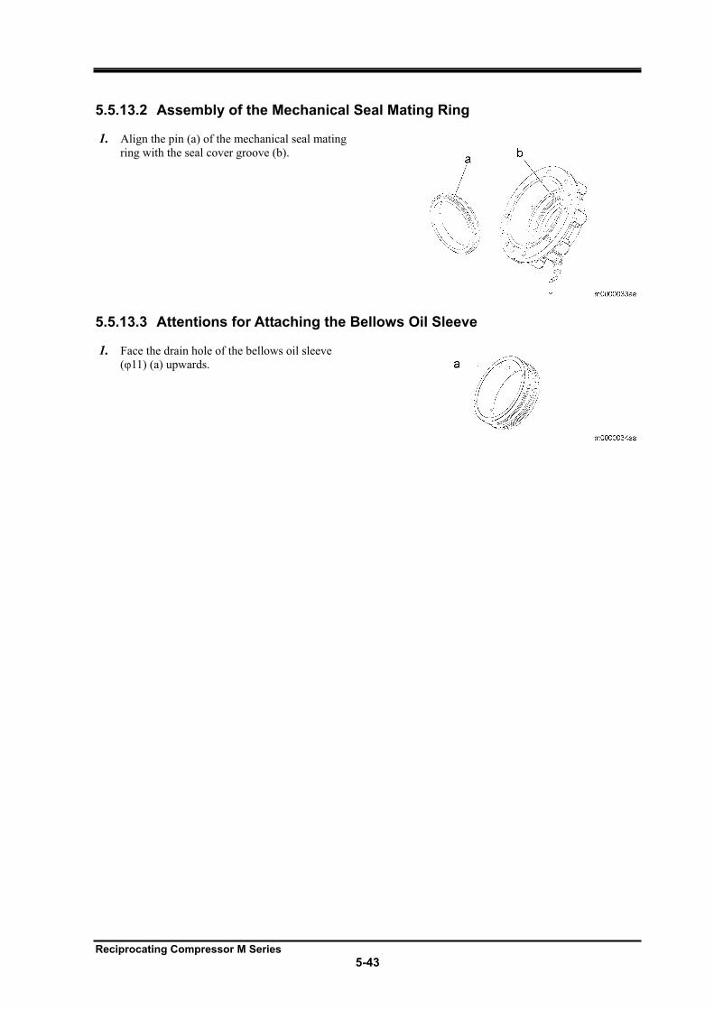
Reciprocating Compressor M Series
5-43
5.5.13.2 Assembly of the Mechanical Seal Mating Ring
1. Align the pin (a) of the mechanical seal mating
ring with the seal cover groove (b).
5.5.13.3 Attentions for Attaching the Bellows Oil Sleeve
1. Face the drain hole of the bellows oil sleeve
( 11) (a) upwards.
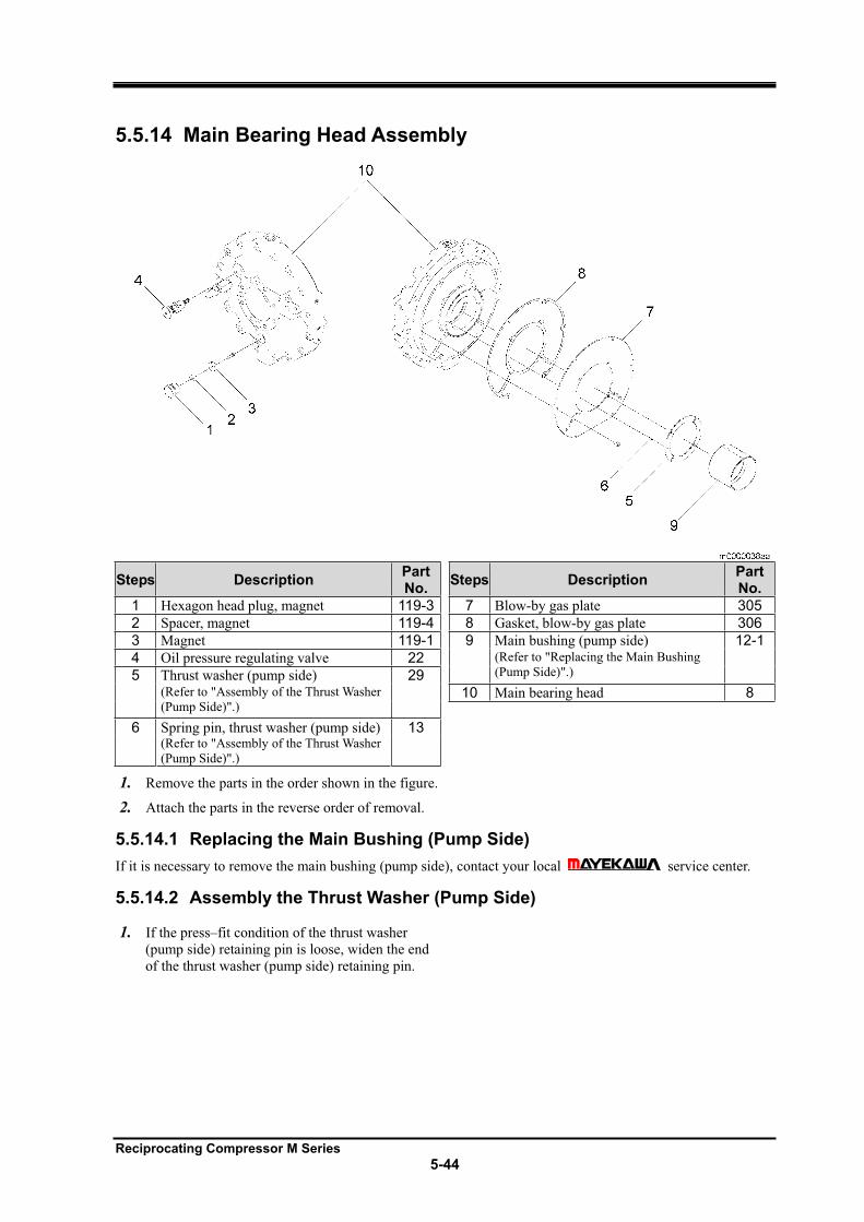
Reciprocating Compressor M Series
5-44
5.5.14 Main Bearing Head Assembly
Steps Description PartNo.
Steps Description PartNo.
1 Hexagon head plug, magnet 119-3 7 Blow-by gas plate 305
2 Spacer, magnet 119-4 8 Gasket, blow-by gas plate 306
3 Magnet 119-1 9 Main bushing (pump side) 12-1
4 Oil pressure regulating valve 22 (Refer to "Replacing the Main Bushing
(Pump Side)".) 5 Thrust washer (pump side) 29 (Refer to "Assembly of the Thrust Washer
(Pump Side)".) 10 Main bearing head 8
6 Spring pin, thrust washer (pump side) 13 (Refer to "Assembly of the Thrust Washer
(Pump Side)".)
1. Remove the parts in the order shown in the figure.
2. Attach the parts in the reverse order of removal.
5.5.14.1 Replacing the Main Bushing (Pump Side)
If it is necessary to remove the main bushing (pump side), contact your local service center.
5.5.14.2 Assembly the Thrust Washer (Pump Side)
1. If the press–fit condition of the thrust washer
(pump side) retaining pin is loose, widen the end
of the thrust washer (pump side) retaining pin.
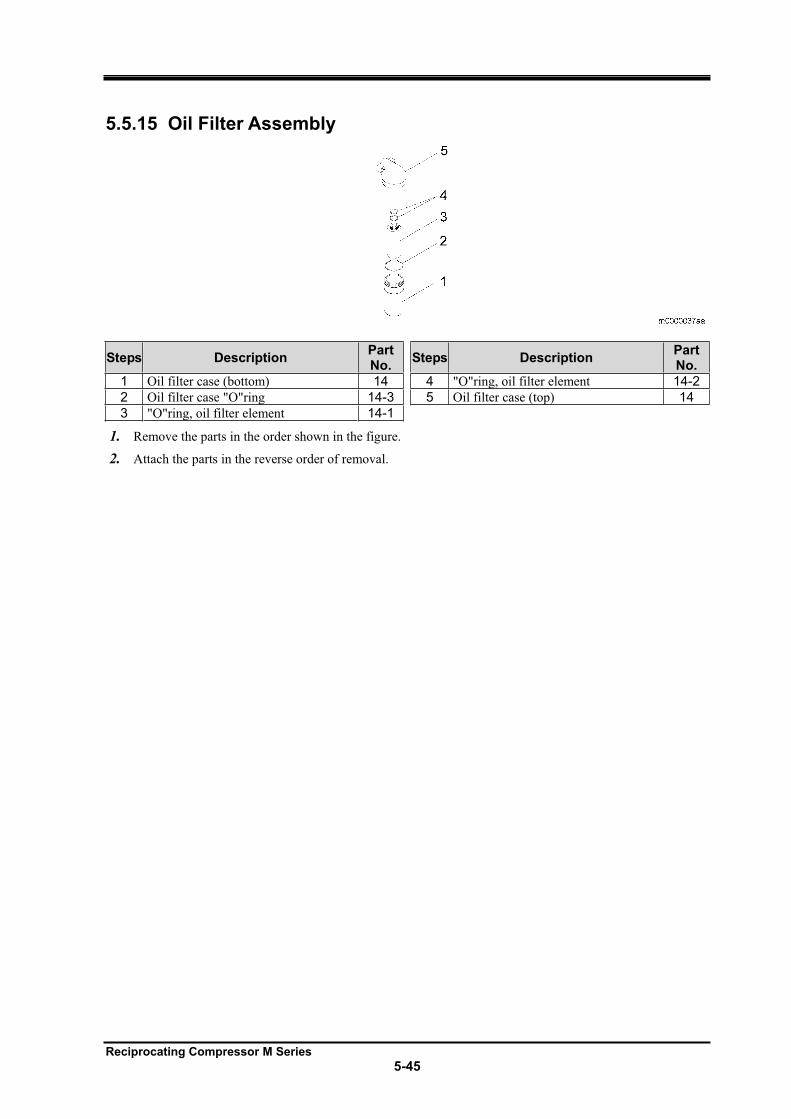
Reciprocating Compressor M Series
5-45
5.5.15 Oil Filter Assembly
Steps Description PartNo.
Steps Description PartNo.
1 Oil filter case (bottom) 14 4 "O"ring, oil filter element 14-2
2 Oil filter case "O"ring 14-3 5 Oil filter case (top) 14
3 "O"ring, oil filter element 14-1
1. Remove the parts in the order shown in the figure.
2. Attach the parts in the reverse order of removal.
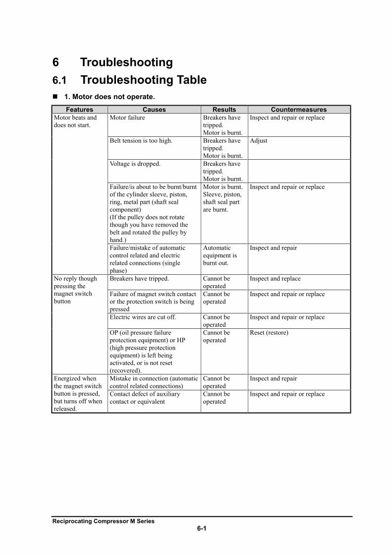
Reciprocating Compressor M Series
6-1
6 Troubleshooting
6.1 Troubleshooting Table
1. Motor does not operate.
Features Causes Results Countermeasures
Motor beats and
does not start.
Motor failure Breakers have
tripped.
Motor is burnt.
Inspect and repair or replace
Belt tension is too high. Breakers have
tripped.
Motor is burnt.
Adjust
Voltage is dropped. Breakers have
tripped.
Motor is burnt.
Failure/is about to be burnt/burnt
of the cylinder sleeve, piston,
ring, metal part (shaft seal
component)
(If the pulley does not rotate
though you have removed the
belt and rotated the pulley by
hand.)
Motor is burnt.
Sleeve, piston,
shaft seal part
are burnt.
Inspect and repair or replace
Failure/mistake of automatic
control related and electric
related connections (single
phase)
Automatic
equipment is
burnt out.
Inspect and repair
No reply though
pressing the
magnet switch
button
Breakers have tripped. Cannot be
operated
Inspect and replace
Failure of magnet switch contact
or the protection switch is being
pressed
Cannot be
operated
Inspect and repair or replace
Electric wires are cut off. Cannot be
operated
Inspect and repair or replace
OP (oil pressure failure
protection equipment) or HP
(high pressure protection
equipment) is left being
activated, or is not reset
(recovered).
Cannot be
operated
Reset (restore)
Energized when
the magnet switch
button is pressed,
but turns off when
released.
Mistake in connection (automatic
control related connections)
Cannot be
operated
Inspect and repair
Contact defect of auxiliary
contact or equivalent
Cannot be
operated
Inspect and repair or replace
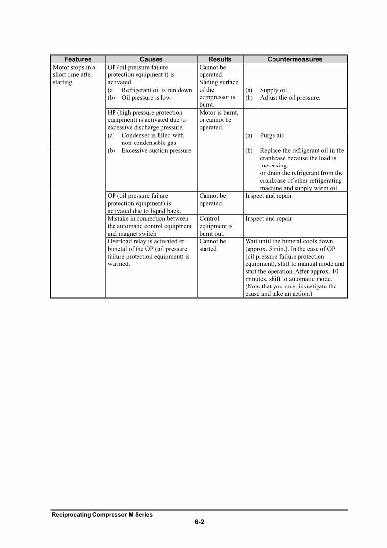
Reciprocating Compressor M Series
6-2
Features Causes Results Countermeasures
Motor stops in a
short time after
starting.
OP (oil pressure failure
protection equipment t) is
activated.
Cannot be
operated.
Sliding surface
of the
compressor is
burnt.
(a) Refrigerant oil is run down. (a) Supply oil.
(b) Oil pressure is low. (b) Adjust the oil pressure.
HP (high pressure protection
equipment) is activated due to
excessive discharge pressure.
Motor is burnt,
or cannot be
operated.
(a) Condenser is filled with
non-condensable gas.
(a) Purge air.
(b) Excessive suction pressure (b) Replace the refrigerant oil in the
crankcase because the load is
increasing,
or drain the refrigerant from the
crankcase of other refrigerating
machine and supply warm oil.
OP (oil pressure failure
protection equipment) is
activated due to liquid back.
Cannot be
operated
Inspect and repair
Mistake in connection between
the automatic control equipment
and magnet switch
Control
equipment is
burnt out.
Inspect and repair
Overload relay is activated or
bimetal of the OP (oil pressure
failure protection equipment) is
warmed.
Cannot be
started
Wait until the bimetal cools down
(approx. 5 min.). In the case of OP
(oil pressure failure protection
equipment), shift to manual mode and
start the operation. After approx. 10
minutes, shift to automatic mode.
(Note that you must investigate the
cause and take an action.)
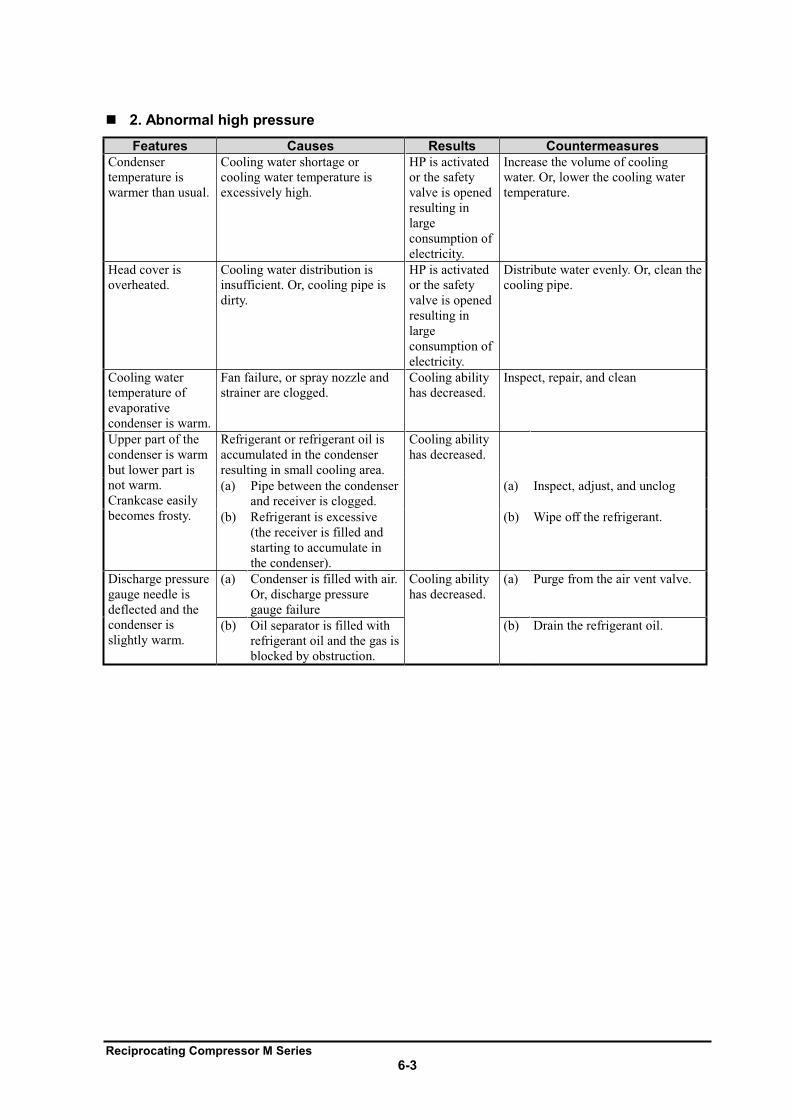
Reciprocating Compressor M Series
6-3
2. Abnormal high pressure
Features Causes Results Countermeasures
Condenser
temperature is
warmer than usual.
Cooling water shortage or
cooling water temperature is
excessively high.
HP is activated
or the safety
valve is opened
resulting in
large
consumption of
electricity.
Increase the volume of cooling
water. Or, lower the cooling water
temperature.
Head cover is
overheated.
Cooling water distribution is
insufficient. Or, cooling pipe is
dirty.
HP is activated
or the safety
valve is opened
resulting in
large
consumption of
electricity.
Distribute water evenly. Or, clean the
cooling pipe.
Cooling water
temperature of
evaporative
condenser is warm.
Fan failure, or spray nozzle and
strainer are clogged.
Cooling ability
has decreased.
Inspect, repair, and clean
Upper part of the
condenser is warm
but lower part is
not warm.
Crankcase easily
becomes frosty.
Refrigerant or refrigerant oil is
accumulated in the condenser
resulting in small cooling area.
Cooling ability
has decreased.
(a) Pipe between the condenser
and receiver is clogged.
(a) Inspect, adjust, and unclog
(b) Refrigerant is excessive
(the receiver is filled and
starting to accumulate in
the condenser).
(b) Wipe off the refrigerant.
Discharge pressure
gauge needle is
deflected and the
condenser is
slightly warm.
(a) Condenser is filled with air.
Or, discharge pressure
gauge failure
Cooling ability
has decreased.
(a) Purge from the air vent valve.
(b) Oil separator is filled with
refrigerant oil and the gas is
blocked by obstruction.
(b) Drain the refrigerant oil.
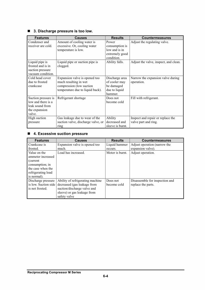
Reciprocating Compressor M Series
6-4
3. Discharge pressure is too low.
Features Causes Results Countermeasures
Condenser and
receiver are cold.
Amount of cooling water is
excessive. Or, cooling water
temperature is low.
Power
consumption is
low and is in
extremely good
condition.
Adjust the regulating valve.
Liquid pipe is
frosted and is in
suction pressure
vacuum condition.
Liquid pipe or suction pipe is
clogged.
Ability falls. Adjust the valve, inspect, and clean.
Cold head cover
due to frosted
crankcase
Expansion valve is opened too
much resulting in wet
compression (low suction
temperature due to liquid back).
Discharge area
of cooler may
be damaged
due to liquid
hammer.
Narrow the expansion valve during
operation.
Suction pressure is
low and there is a
leak sound from
the expansion
valve.
Refrigerant shortage Does not
become cold
Fill with refrigerant.
High suction
pressure
Gas leakage due to wear of the
suction valve, discharge valve, or
ring
Ability
decreased and
sleeve is burnt.
Inspect and repair or replace the
valve part and ring.
4. Excessive suction pressure
Features Causes Results Countermeasures
Crankcase is
frosted.
Expansion valve is opened too
much.
Liquid hammer
occurs.
Adjust operation (narrow the
expansion valve).
Value on the
ammeter increased
(current
consumption; in
the case when the
refrigerating load
is normal).
Load has increased. Motor is burnt. Adjust operation.
Discharge pressure
is low. Suction side
is not frosted.
Ability of refrigerating machine
decreased (gas leakage from
suction/discharge valve and
sleeve) or gas leakage from
safety valve
Does not
become cold
Disassemble for inspection and
replace the parts.
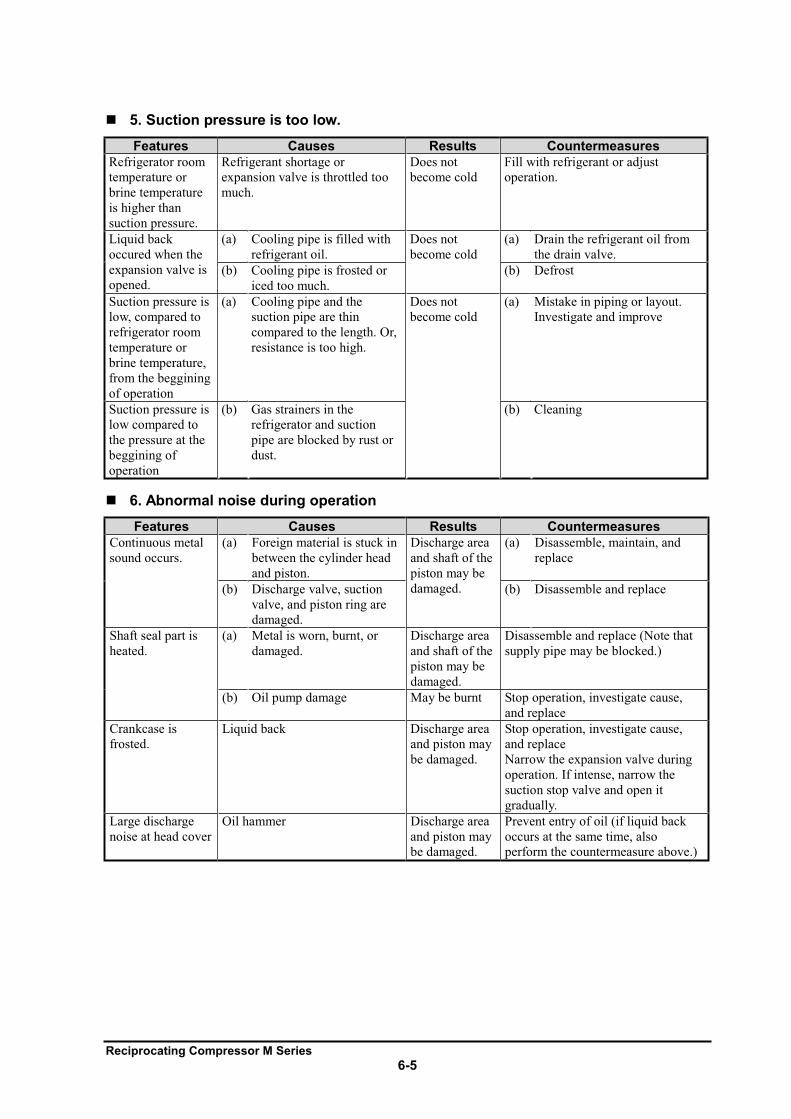
Reciprocating Compressor M Series
6-5
5. Suction pressure is too low.
Features Causes Results Countermeasures
Refrigerator room
temperature or
brine temperature
is higher than
suction pressure.
Refrigerant shortage or
expansion valve is throttled too
much.
Does not
become cold
Fill with refrigerant or adjust
operation.
Liquid back
occured when the
expansion valve is
opened.
(a) Cooling pipe is filled with
refrigerant oil.
Does not
become cold
(a) Drain the refrigerant oil from
the drain valve.
(b) Cooling pipe is frosted or
iced too much.
(b) Defrost
Suction pressure is
low, compared to
refrigerator room
temperature or
brine temperature,
from the beggining
of operation
(a) Cooling pipe and the
suction pipe are thin
compared to the length. Or,
resistance is too high.
Does not
become cold
(a) Mistake in piping or layout.
Investigate and improve
Suction pressure is
low compared to
the pressure at the
beggining of
operation
(b) Gas strainers in the
refrigerator and suction
pipe are blocked by rust or
dust.
(b) Cleaning
6. Abnormal noise during operation
Features Causes Results Countermeasures
Continuous metal
sound occurs.
(a) Foreign material is stuck in
between the cylinder head
and piston.
Discharge area
and shaft of the
piston may be
damaged.
(a) Disassemble, maintain, and
replace
(b) Discharge valve, suction
valve, and piston ring are
damaged.
(b) Disassemble and replace
Shaft seal part is
heated.
(a) Metal is worn, burnt, or
damaged.
Discharge area
and shaft of the
piston may be
damaged.
Disassemble and replace (Note that
supply pipe may be blocked.)
(b) Oil pump damage May be burnt Stop operation, investigate cause,
and replace
Crankcase is
frosted.
Liquid back Discharge area
and piston may
be damaged.
Stop operation, investigate cause,
and replace
Narrow the expansion valve during
operation. If intense, narrow the
suction stop valve and open it
gradually.
Large discharge
noise at head cover
Oil hammer Discharge area
and piston may
be damaged.
Prevent entry of oil (if liquid back
occurs at the same time, also
perform the countermeasure above.)
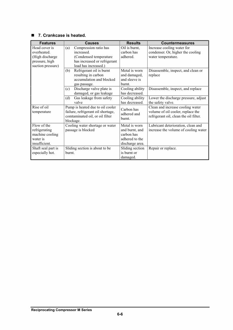
Reciprocating Compressor M Series
6-6
7. Crankcase is heated.
Features Causes Results Countermeasures
Head cover is
overheated.
(High discharge
pressure, high
suction pressure)
(a) Compression ratio has
increased.
(Condensed temperature
has increased or refrigerant
load has increased.)
Oil is burnt,
carbon has
adhered.
Increase cooling water for
condenser. Or, higher the cooling
water temperature.
(b) Refrigerant oil is burnt
resulting in carbon
accumulation and blocked
gas passage.
Metal is worn
and damaged,
and sleeve is
burnt.
Disassemble, inspect, and clean or
replace
(c) Discharge valve plate is
damaged, or gas leakage
Cooling ability
has decreased.
Disassemble, inspect, and replace
(d) Gas leakage from safety
valve
Cooling ability
has decreased.
Lower the discharge pressure, adjust
the safety valve.
Rise of oil
temperature
Pump is heated due to oil cooler
failure, refrigerant oil shortage,
comtaminated oil, or oil filter
blockage.
Carbon has
adhered and
burnt.
Clean and increase cooling water
volume of oil cooler, replace the
refrigerant oil, clean the oil filter.
Flow of the
refrigerating
machine cooling
water is
insufficient.
Cooling water shortage or water
passage is blocked
Metal is worn
and burnt, and
carbon has
adhered to the
discharge area.
Lubricant deterioration, clean and
increase the volume of cooling water
Shaft seal part is
especially hot.
Sliding section is about to be
burnt.
Sliding section
is burnt or
damaged.
Repair or replace.
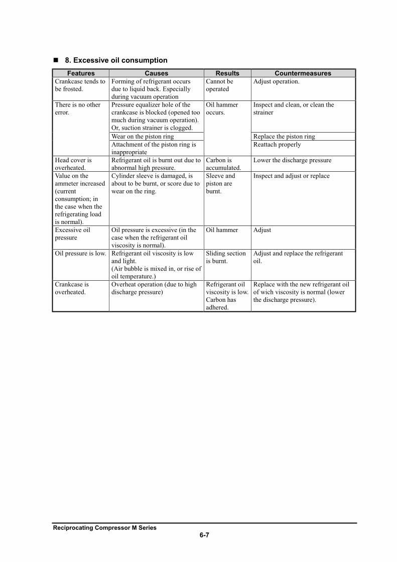
Reciprocating Compressor M Series
6-7
8. Excessive oil consumption
Features Causes Results Countermeasures
Crankcase tends to
be frosted.
Forming of refrigerant occurs
due to liquid back. Especially
during vacuum operation
Cannot be
operated
Adjust operation.
There is no other
error.
Pressure equalizer hole of the
crankcase is blocked (opened too
much during vacuum operation).
Or, suction strainer is clogged.
Oil hammer
occurs.
Inspect and clean, or clean the
strainer
Wear on the piston ring Replace the piston ring
Attachment of the piston ring is
inappropriate
Reattach properly
Head cover is
overheated.
Refrigerant oil is burnt out due to
abnormal high pressure.
Carbon is
accumulated.
Lower the discharge pressure
Value on the
ammeter increased
(current
consumption; in
the case when the
refrigerating load
is normal).
Cylinder sleeve is damaged, is
about to be burnt, or score due to
wear on the ring.
Sleeve and
piston are
burnt.
Inspect and adjust or replace
Excessive oil
pressure
Oil pressure is excessive (in the
case when the refrigerant oil
viscosity is normal).
Oil hammer Adjust
Oil pressure is low. Refrigerant oil viscosity is low
and light.
(Air bubble is mixed in, or rise of
oil temperature.)
Sliding section
is burnt.
Adjust and replace the refrigerant
oil.
Crankcase is
overheated.
Overheat operation (due to high
discharge pressure)
Refrigerant oil
viscosity is low.
Carbon has
adhered.
Replace with the new refrigerant oil
of wich viscosity is normal (lower
the discharge pressure).
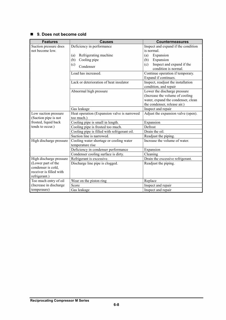
Reciprocating Compressor M Series
6-8
9. Does not become cold
Features Causes Countermeasures
Suction pressure does
not become low.
Deficiency in performance Inspect and expand if the condition
is normal.
(a) Refrigerating machine (a) Expansion
(b) Cooling pipe (b) Expansion
(c) Condenser
(c) Inspect and expand if the
condition is normal.
Load has increased. Continue operation if temporary.
Expand if continues.
Lack or deterioration of heat insulator Inspect, readjust the installation
condition, and repair
Abnormal high pressure Lower the discharge pressure
(Increase the volume of cooling
water, expand the condenser, clean
the condenser, release air.)
Gas leakage Inspect and repair
Low suction pressure
(Suction pipe is not
frosted, liquid back
tends to occur.)
Heat operation (Expansion valve is narrowed
too much.)
Adjust the expansion valve (open).
Cooling pipe is small in length. Expansion
Cooling pipe is frosted too much. Defrost
Cooling pipe is filled with refrigerant oil. Drain the oil.
Suction line is narrowed. Readjust the piping.
High discharge pressure Cooling water shortage or cooling water
temperature rise
Increase the volume of water.
Deficiency in condenser performance Expansion
Condenser cooling surface is dirty. Cleaning
High discharge pressure
(Lower part of the
condenser is cold,
receiver is filled with
refrigerant.)
Refrigerant is excessive. Drain the excessive refrigerant.
Discharge line pipe is clogged. Readjust the piping.
Too much entry of oil
(Increase in discharge
temperaure)
Wear on the piston ring Replace
Score Inspect and repair
Gas leakage Inspect and repair
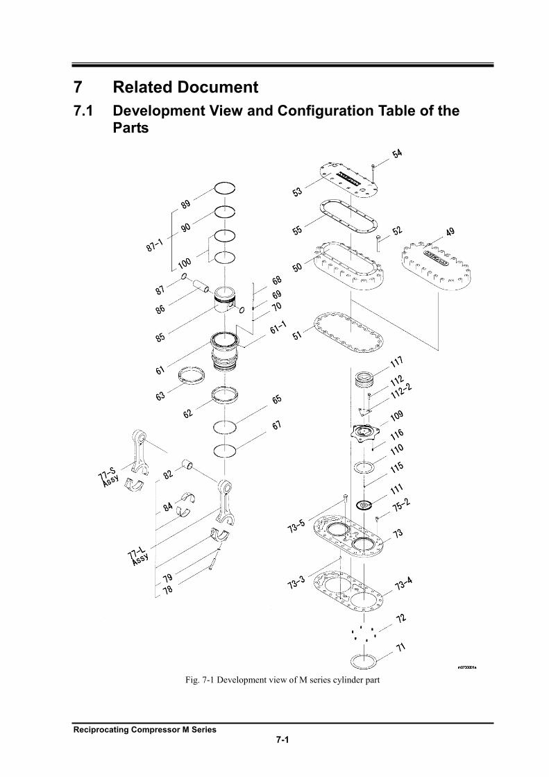
Reciprocating Compressor M Series
7-1
7 Related Document
7.1 Development View and Configuration Table of the Parts
Fig. 7-1 Development view of M series cylinder part
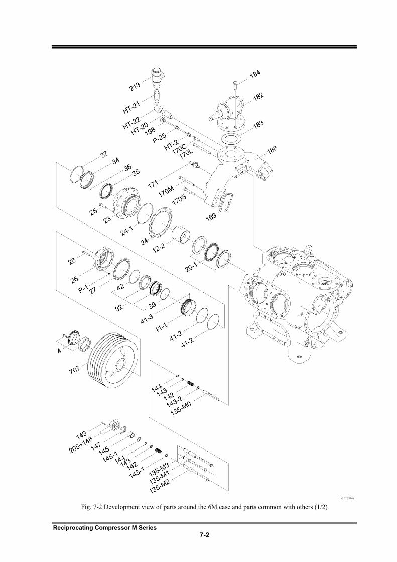
Reciprocating Compressor M Series
7-2
Fig. 7-2 Development view of parts around the 6M case and parts common with others (1/2)
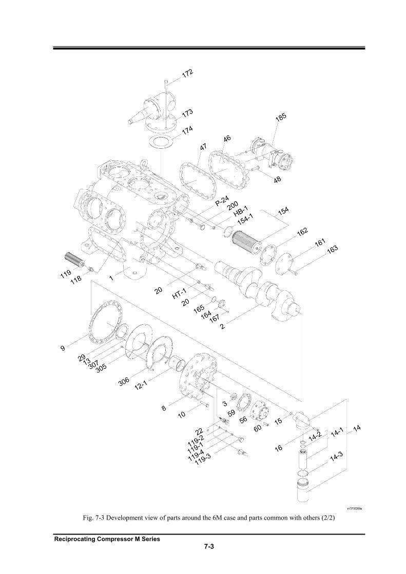
Reciprocating Compressor M Series
7-3
Fig. 7-3 Development view of parts around the 6M case and parts common with others (2/2)
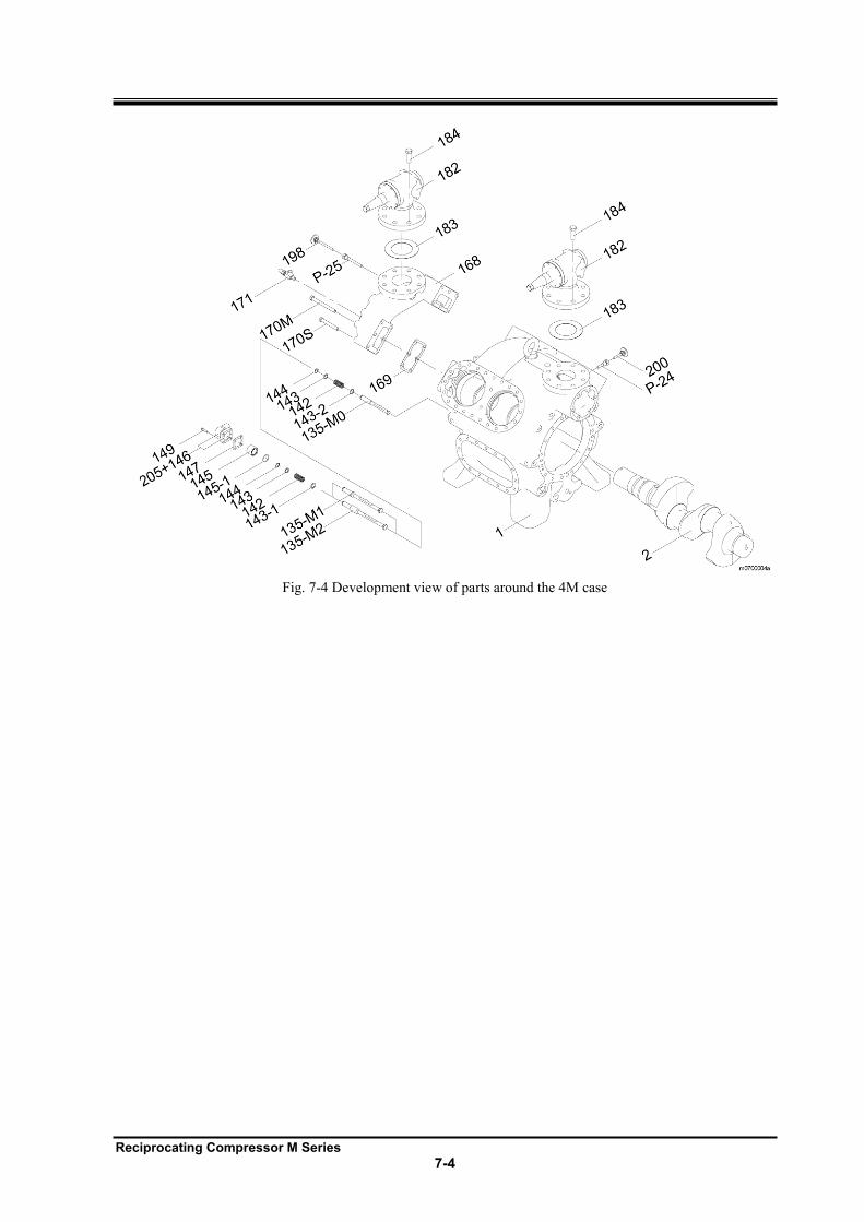
Reciprocating Compressor M Series
7-4
Fig. 7-4 Development view of parts around the 4M case
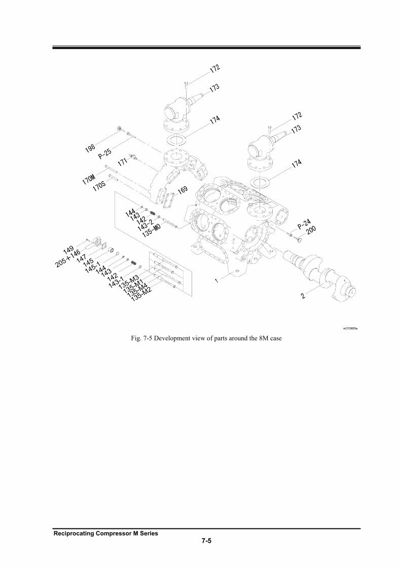
Reciprocating Compressor M Series
7-5
Fig. 7-5 Development view of parts around the 8M case
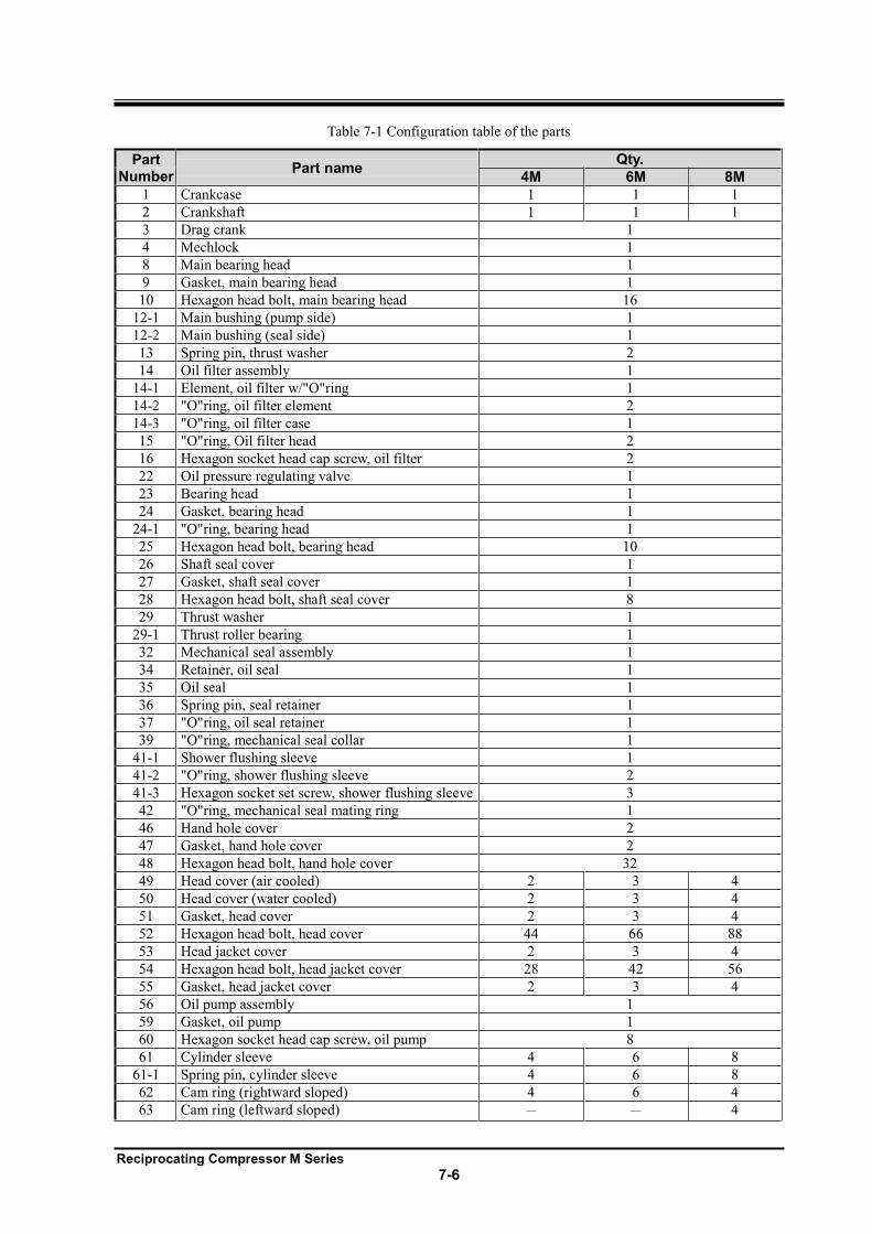
Reciprocating Compressor M Series
7-6
Table 7-1 Configuration table of the parts
Part Number
Part name Qty.
4M 6M 8M
1 Crankcase 1 1 1
2 Crankshaft 1 1 1
3 Drag crank 1
4 Mechlock 1
8 Main bearing head 1
9 Gasket, main bearing head 1
10 Hexagon head bolt, main bearing head 16
12-1 Main bushing (pump side) 1
12-2 Main bushing (seal side) 1
13 Spring pin, thrust washer 2
14 Oil filter assembly 1
14-1 Element, oil filter w/"O"ring 1
14-2 "O"ring, oil filter element 2
14-3 "O"ring, oil filter case 1
15 "O"ring, Oil filter head 2
16 Hexagon socket head cap screw, oil filter 2
22 Oil pressure regulating valve 1
23 Bearing head 1
24 Gasket, bearing head 1
24-1 "O"ring, bearing head 1
25 Hexagon head bolt, bearing head 10
26 Shaft seal cover 1
27 Gasket, shaft seal cover 1
28 Hexagon head bolt, shaft seal cover 8
29 Thrust washer 1
29-1 Thrust roller bearing 1
32 Mechanical seal assembly 1
34 Retainer, oil seal 1
35 Oil seal 1
36 Spring pin, seal retainer 1
37 "O"ring, oil seal retainer 1
39 "O"ring, mechanical seal collar 1
41-1 Shower flushing sleeve 1
41-2 "O"ring, shower flushing sleeve 2
41-3 Hexagon socket set screw, shower flushing sleeve 3
42 "O"ring, mechanical seal mating ring 1
46 Hand hole cover 2
47 Gasket, hand hole cover 2
48 Hexagon head bolt, hand hole cover 32
49 Head cover (air cooled) 2 3 4
50 Head cover (water cooled) 2 3 4
51 Gasket, head cover 2 3 4
52 Hexagon head bolt, head cover 44 66 88
53 Head jacket cover 2 3 4
54 Hexagon head bolt, head jacket cover 28 42 56
55 Gasket, head jacket cover 2 3 4
56 Oil pump assembly 1
59 Gasket, oil pump 1
60 Hexagon socket head cap screw, oil pump 8
61 Cylinder sleeve 4 6 8
61-1 Spring pin, cylinder sleeve 4 6 8
62 Cam ring (rightward sloped) 4 6 4
63 Cam ring (leftward sloped) 4
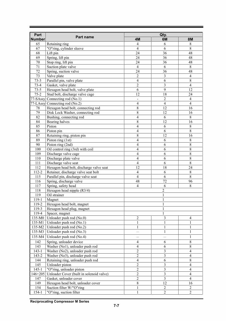
Reciprocating Compressor M Series
7-7
Part Number
Part name Qty.
4M 6M 8M
65 Retaining ring 4 6 8
67 "O"ring, cylinder sleeve 4 6 8
68 Lift pin 24 36 48
69 Spring, lift pin 24 36 48
70 Stop ring, lift pin 24 36 48
71 Suction plate valve 4 6 8
72 Spring, suction valve 24 36 48
73 Valve plate 2 3 4
73-3 Parallel pin, valve plate 4 6 8
73-4 Gasket, valve plate 2 3 4
73-5 Hexagon head bolt, valve plate 6 9 12
75-2 Stud bolt, discharge valve cage 12 18 24
77-SAssy Connecting rod (No.1) - 2 4
77-LAssy Connecting rod (No.2) 4 4 4
78 Hexagon head bolt, connecting rod 8 12 16
79 Disk Lock Washer, connecting rod 8 12 16
82 Bushing, connecting rod 4 6 8
84 Bearing halves 8 12 16
85 Piston 4 6 8
86 Piston pin 4 6 8
87 Retaining ring, piston pin 8 12 16
89 Piston ring (1st) 4 6 8
90 Piston ring (2nd) 4 6 8
100 Oil control ring (3rd) with coil 4 6 8
109 Discharge valve cage 4 6 8
110 Discharge plate valve 4 6 8
111 Discharge valve seat 4 6 8
112 Hexagon head bolt, discharge valve seat 12 18 24
112-2 Retainer, discharge valve seat bolt 4 6 8
115 Parallel pin, discharge valve seat 4 6 8
116 Spring, discharge valve 48 72 96
117 Spring, safety head 4 6 8
118 Hexagon head nipple (R3/4) 2
119 Oil strainer 1
119-1 Magnet 1
119-2 Hexagon head bolt, magnet 1
119-3 Hexagon head plug, magnet 1
119-4 Spacer, magnet 1
135-M0 Unloader push rod (No.0) 2 3 4
135-M1 Unloader push rod (No.1) 1 1 1
135-M2 Unloader push rod (No.2) 1 1 1
135-M3 Unloader push rod (No.3) 1 1
135-M4 Unloader push rod (No.4) 1
142 Spring, unloader device 4 6 8
143 Washer (No1), unloader push rod 4 6 8
143-1 Washer (No2), unloader push rod 2 3 4
143-2 Washer (No3), unloader push rod 2 3 4
144 Retaining ring, unloader push rod 4 6 8
145 Unloader piston 2 3 4
145-1 "O"ring, unloader piston 2 3 4
146+205 Unloader Cover (built in solenoid valve) 2 3 4
147 Gasket, unloader cover 2 3 4
149 Hexagon head bolt, unloader cover 8 12 16
154 Suction filter W/"O"ring 1 2 2
154-1 "O"ring, suction filter 1 2 2
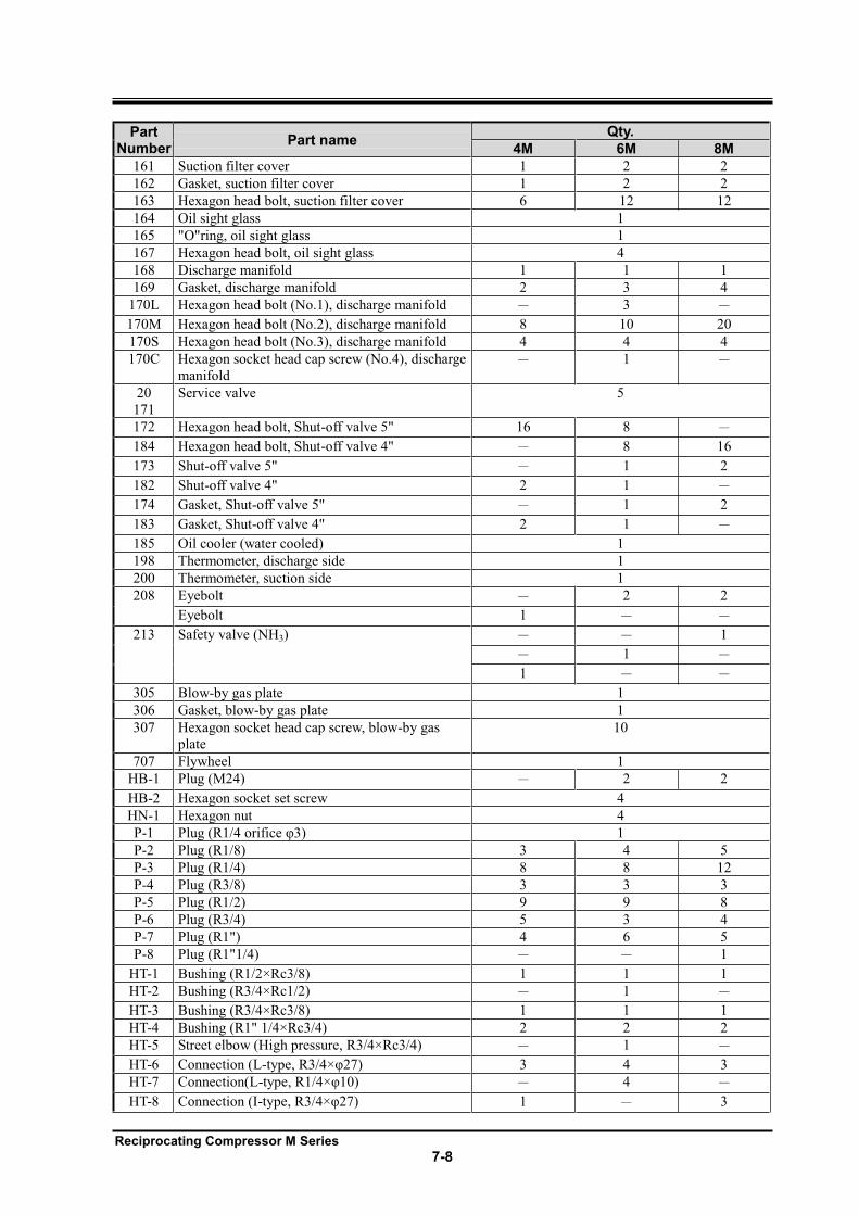
Reciprocating Compressor M Series
7-8
Part Number
Part name Qty.
4M 6M 8M
161 Suction filter cover 1 2 2
162 Gasket, suction filter cover 1 2 2
163 Hexagon head bolt, suction filter cover 6 12 12
164 Oil sight glass 1
165 "O"ring, oil sight glass 1
167 Hexagon head bolt, oil sight glass 4
168 Discharge manifold 1 1 1
169 Gasket, discharge manifold 2 3 4
170L Hexagon head bolt (No.1), discharge manifold 3
170M Hexagon head bolt (No.2), discharge manifold 8 10 20
170S Hexagon head bolt (No.3), discharge manifold 4 4 4
170C Hexagon socket head cap screw (No.4), discharge
manifold 1
20
171
Service valve 5
172 Hexagon head bolt, Shut-off valve 5" 16 8
184 Hexagon head bolt, Shut-off valve 4" 8 16
173 Shut-off valve 5" 1 2
182 Shut-off valve 4" 2 1
174 Gasket, Shut-off valve 5" 1 2
183 Gasket, Shut-off valve 4" 2 1
185 Oil cooler (water cooled) 1
198 Thermometer, discharge side 1
200 Thermometer, suction side 1
208 Eyebolt 2 2
Eyebolt 1
213 Safety valve (NH3) 1
1
1
305 Blow-by gas plate 1
306 Gasket, blow-by gas plate 1
307 Hexagon socket head cap screw, blow-by gas
plate
10
707 Flywheel 1
HB-1 Plug (M24) 2 2
HB-2 Hexagon socket set screw 4
HN-1 Hexagon nut 4
P-1 1
P-2 Plug (R1/8) 3 4 5
P-3 Plug (R1/4) 8 8 12
P-4 Plug (R3/8) 3 3 3
P-5 Plug (R1/2) 9 9 8
P-6 Plug (R3/4) 5 3 4
P-7 Plug (R1") 4 6 5
P-8 Plug (R1"1/4) 1
HT-1 Bushing (R1/2×Rc3/8) 1 1 1
HT-2 Bushing (R3/4×Rc1/2) 1
HT-3 Bushing (R3/4×Rc3/8) 1 1 1
HT-4 Bushing (R1" 1/4×Rc3/4) 2 2 2
HT-5 Street elbow (High pressure, R3/4×Rc3/4) 1
HT-6 Connection (L- 3 4 3
HT-7 Connection(L- 4
HT-8 Connection (I- 1 3
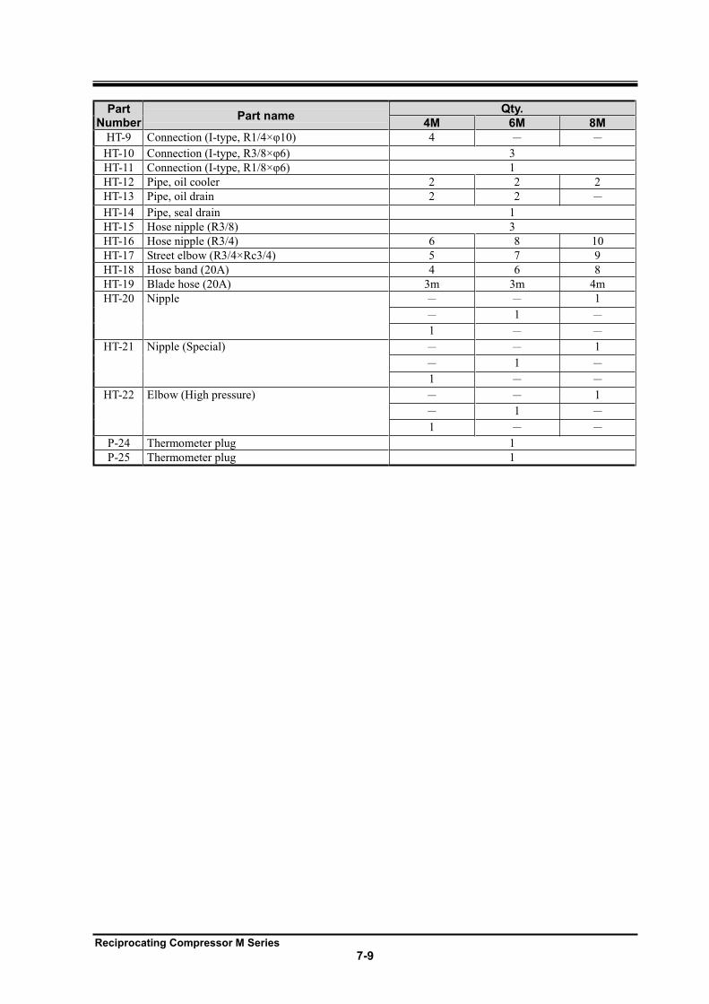
Reciprocating Compressor M Series
7-9
Part Number
Part name Qty.
4M 6M 8M
HT-9 Connection (I- 4
HT-10 Connection (I- 3
HT-11 Connection (I- 1
HT-12 Pipe, oil cooler 2 2 2
HT-13 Pipe, oil drain 2 2
HT-14 Pipe, seal drain 1
HT-15 Hose nipple (R3/8) 3
HT-16 Hose nipple (R3/4) 6 8 10
HT-17 Street elbow (R3/4×Rc3/4) 5 7 9
HT-18 Hose band (20A) 4 6 8
HT-19 Blade hose (20A) 3m 3m 4m
HT-20 Nipple 1
1
1
HT-21 Nipple (Special) 1
1
1
HT-22 Elbow (High pressure) 1
1
1
P-24 Thermometer plug 1
P-25 Thermometer plug 1
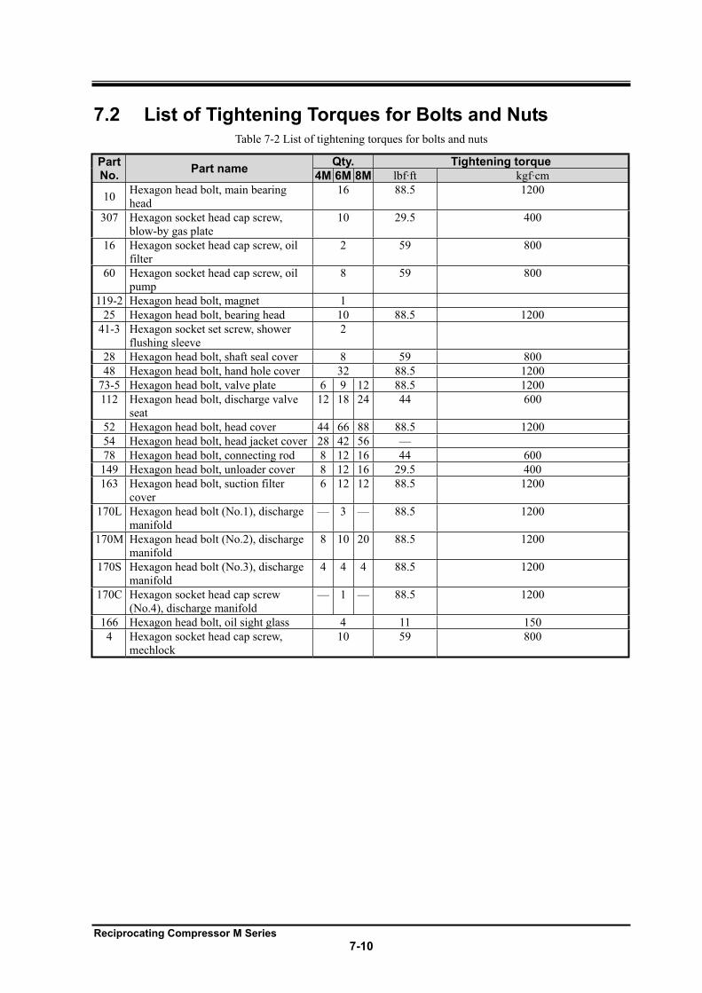
Reciprocating Compressor M Series
7-10
7.2 List of Tightening Torques for Bolts and Nuts Table 7-2 List of tightening torques for bolts and nuts
PartNo.
Part name Qty. Tightening torque
4M 6M 8M lbf·ft kgf·cm
10 Hexagon head bolt, main bearing
head
16 88.5 1200
307 Hexagon socket head cap screw,
blow-by gas plate
10 29.5 400
16 Hexagon socket head cap screw, oil
filter
2 59 800
60 Hexagon socket head cap screw, oil
pump
8 59 800
119-2 Hexagon head bolt, magnet 1
25 Hexagon head bolt, bearing head 10 88.5 1200
41-3 Hexagon socket set screw, shower
flushing sleeve
2
28 Hexagon head bolt, shaft seal cover 8 59 800
48 Hexagon head bolt, hand hole cover 32 88.5 1200
73-5 Hexagon head bolt, valve plate 6 9 12 88.5 1200
112 Hexagon head bolt, discharge valve
seat
12 18 24 44 600
52 Hexagon head bolt, head cover 44 66 88 88.5 1200
54 Hexagon head bolt, head jacket cover 28 42 56 —
78 Hexagon head bolt, connecting rod 8 12 16 44 600
149 Hexagon head bolt, unloader cover 8 12 16 29.5 400
163 Hexagon head bolt, suction filter
cover
6 12 12 88.5 1200
170L Hexagon head bolt (No.1), discharge
manifold
— 3 — 88.5 1200
170M Hexagon head bolt (No.2), discharge
manifold
8 10 20 88.5 1200
170S Hexagon head bolt (No.3), discharge
manifold
4 4 4 88.5 1200
170C Hexagon socket head cap screw
(No.4), discharge manifold
— 1 — 88.5 1200
166 Hexagon head bolt, oil sight glass 4 11 150
4 Hexagon socket head cap screw,
mechlock
10 59 800
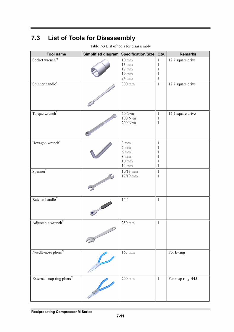
Reciprocating Compressor M Series
7-11
7.3 List of Tools for Disassembly Table 7-3 List of tools for disassembly
Tool name Simplified diagram Specification/Size Qty. Remarks
Socket wrench*1
10 mm
13 mm
17 mm
19 mm
24 mm
1
1
1
1
1
12.7 square drive
Spinner handle*1
300 mm 1 12.7 square drive
Torque wrench*1
1
1
1
12.7 square drive
Hexagon wrench*1
3 mm
5 mm
6 mm
8 mm
10 mm
14 mm
1
1
1
1
1
1
Spanner*1
10/13 mm
17/19 mm
1
1
Ratchet handle*1
1/4" 1
Adjustable wrench*1
250 mm 1
Needle-nose pliers*1
165 mm For E-ring
External snap ring pliers*2
200 mm 1 For snap ring H45
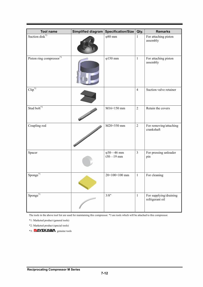
Reciprocating Compressor M Series
7-12
Tool name Simplified diagram Specification/Size Qty. Remarks
Suction disk*3
1 For attaching piston
assembly
Piston ring compressor*3
1 For attaching piston
assembly
Clip*3
4 Suction valve retainer
Stud bolt*3
M16×150 mm 2 Retain the covers
Coupling rod
M20×550 mm 2 For removing/attaching
crankshaft
Spacer
46 mm
t30 19 mm
3 For pressing unloader
pin
Sponge*1
20×100×100 mm 1 For cleaning
Sponge*1
3/8" 1 For supplying/draining
refrigerant oil
The tools in the above tool list are used for maintaining this compressor. *3 are tools which will be attached to this compressor.
*1: Marketed product (general tools)
*2: Marketed product (special tools)
*3: genuine tools
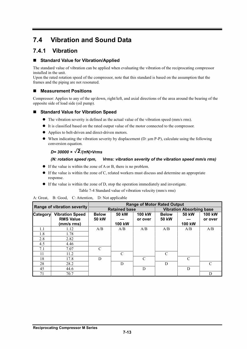
Reciprocating Compressor M Series
7-13
7.4 Vibration and Sound Data
7.4.1 Vibration
Standard Value for Vibration/Applied
The standard value of vibration can be applied when evaluating the vibration of the reciprocating compressor
installed in the unit.
Upon the rated rotation speed of the compressor, note that this standard is based on the assumption that the
frames and the piping are not resonated.
Measurement Positions
Compressor: Applies to any of the up/down, right/left, and axial directions of the area around the bearing of the
opposite side of load side (oil pump).
Standard Value for Vibration Speed
The vibration severity is defined as the actual value of the vibration speed (mm/s rms).
It is classified based on the rated output value of the motor connected to the compressor.
Applies to belt-driven and direct-driven motors.
When indicating the vibration severity by displacement (D: µm P-P), calculate using the following
conversion equation.
D= 30000 ×
(N: rotation speed rpm, Vrms: vibration severity of the vibration speed mm/s rms)
If the value is within the zone of A or B, there is no problem.
If the value is within the zone of C, related workers must discuss and determine an appropriate
response.
If the value is within the zone of D, stop the operation immediately and investigate.
Table 7-4 Standard value of vibration velocity (mm/s rms)
A: Great, B: Good, C: Attention, D: Not applicable
Range of vibration severity Range of Motor Rated Output
Retained base Vibration Absorbing base
Category Vibration Speed RMS Value (mm/s rms)
Below 50 kW
50 kW
100 kW
100 kW or over
Below 50 kW
50 kW
100 kW
100 kW or over
1.1 1.12 A/B A/B A/B A/B A/B A/B
1.8 1.78
2.8 2.82
4.5 4.46
7.1 7.07 C
11 11.2 C C
18 17.8 D C C
28 28.2 D D C
45 44.6 D D
71 70.7 D
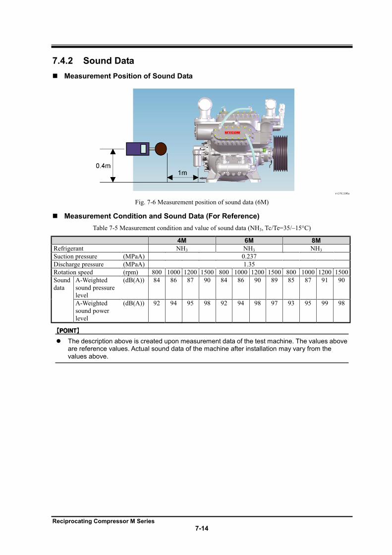
Reciprocating Compressor M Series
7-14
7.4.2 Sound Data
Measurement Position of Sound Data
Fig. 7-6 Measurement position of sound data (6M)
Measurement Condition and Sound Data (For Reference)
Table 7-5 Measurement condition and value of sound data (NH3, Tc/Te=35/ 15°C)
4M 6M 8M
Refrigerant NH3 NH3 NH3
Suction pressure (MPaA) 0.237
Discharge pressure (MPaA) 1.35
Rotation speed (rpm) 800 1000 1200 1500 800 1000 1200 1500 800 1000 1200 1500
Sound
data
A-Weighted
sound pressure
level
(dB(A)) 84 86 87 90 84 86 90 89 85 87 91 90
A-Weighted
sound power
level
(dB(A)) 92 94 95 98 92 94 98 97 93 95 99 98
The description above is created upon measurement data of the test machine. The values above are reference values. Actual sound data of the machine after installation may vary from the values above.
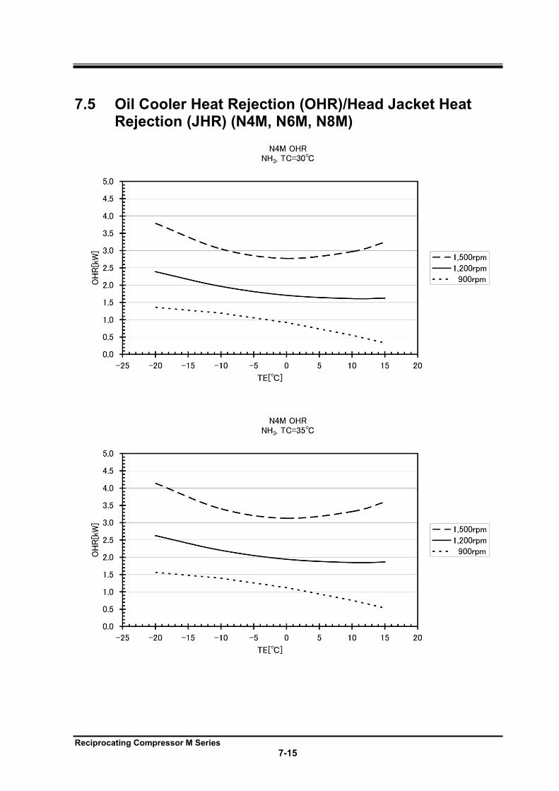
Reciprocating Compressor M Series
7-15
7.5 Oil Cooler Heat Rejection (OHR)/Head Jacket Heat Rejection (JHR) (N4M, N6M, N8M)
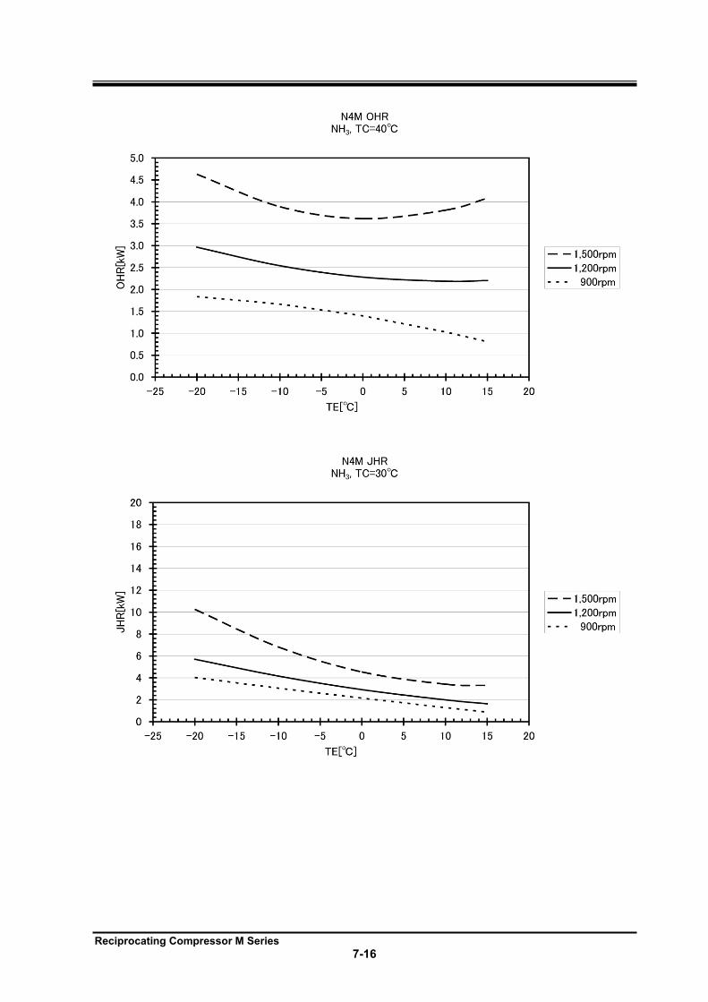
Reciprocating Compressor M Series
7-16
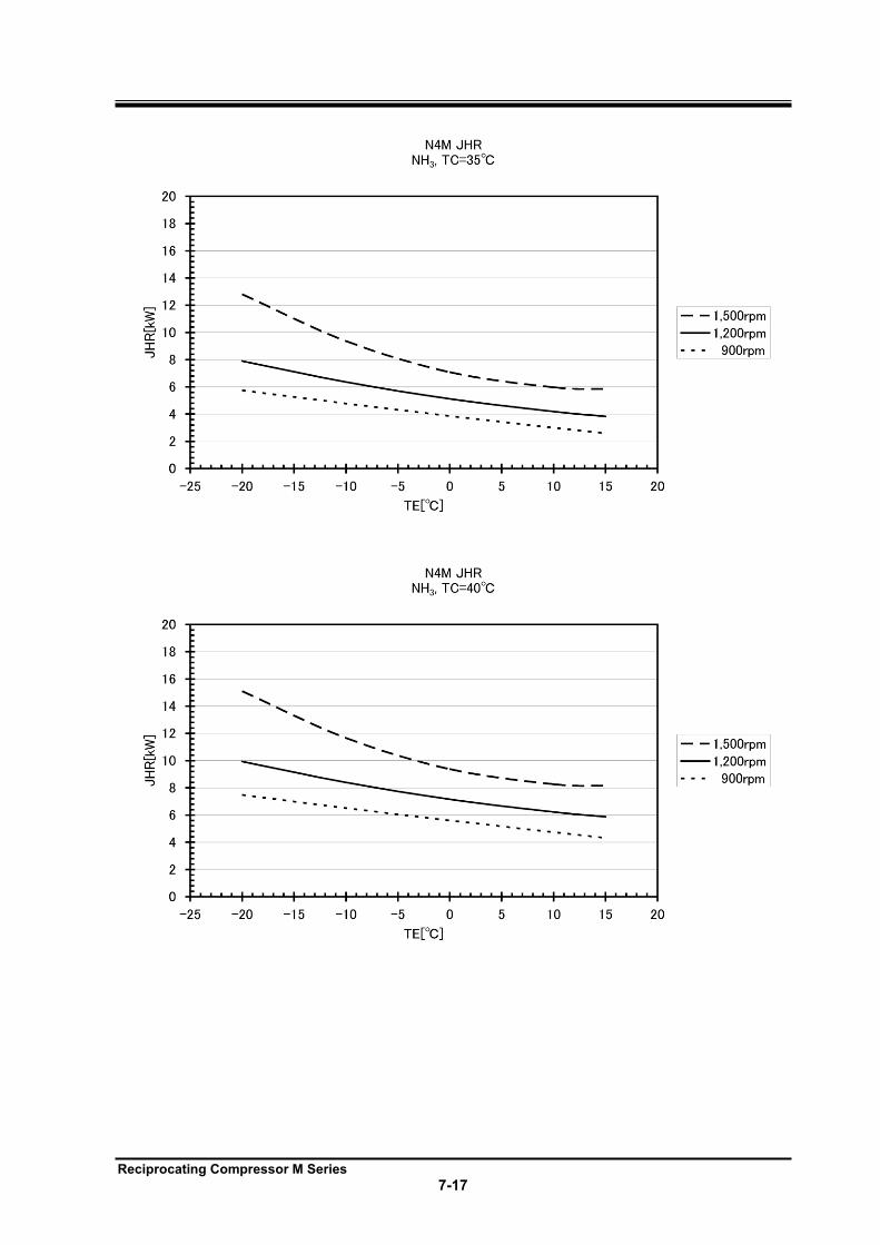
Reciprocating Compressor M Series
7-17
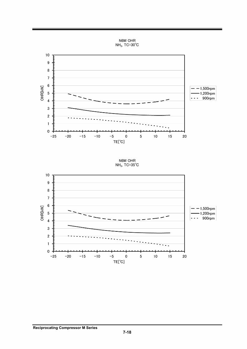
Reciprocating Compressor M Series
7-18
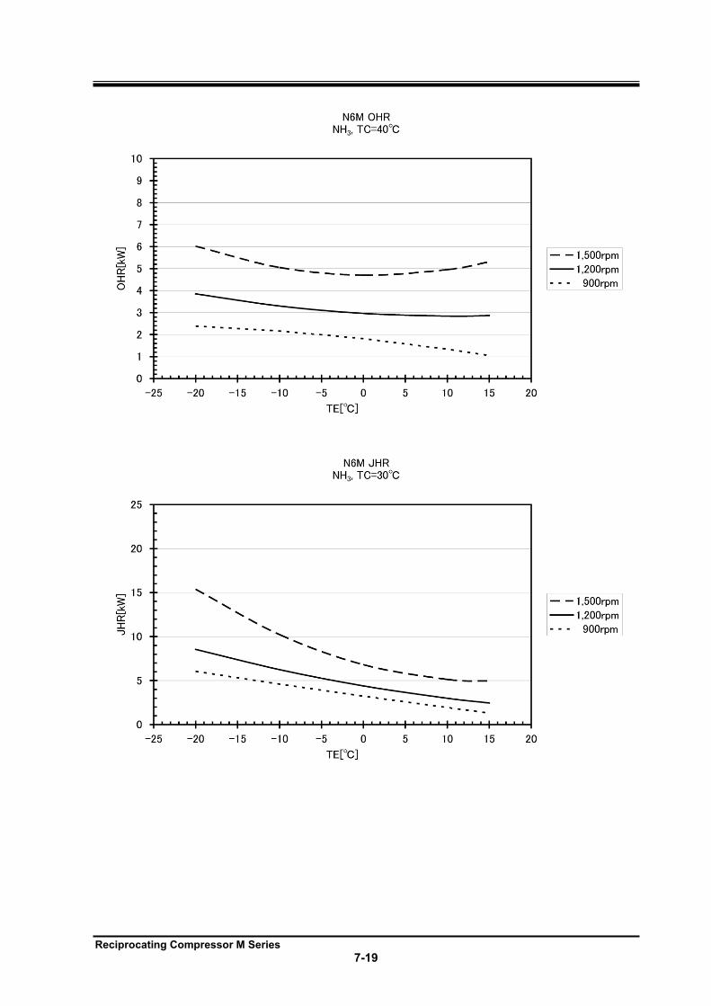
Reciprocating Compressor M Series
7-19
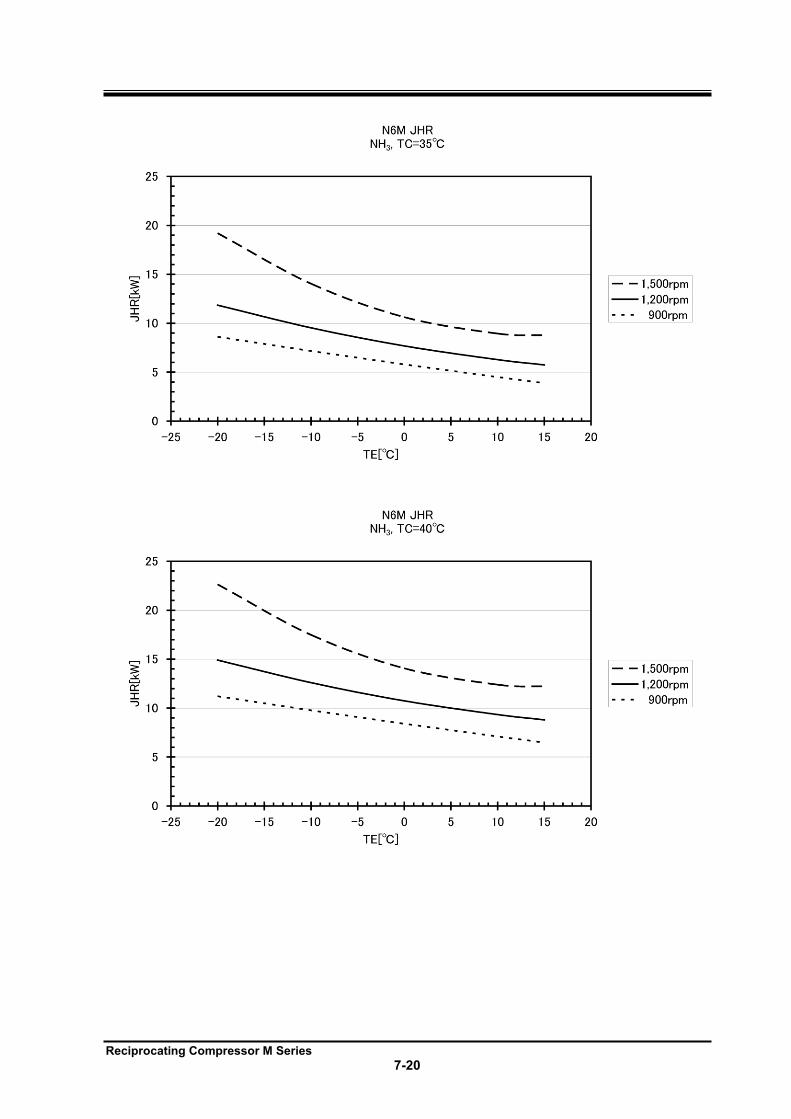
Reciprocating Compressor M Series
7-20
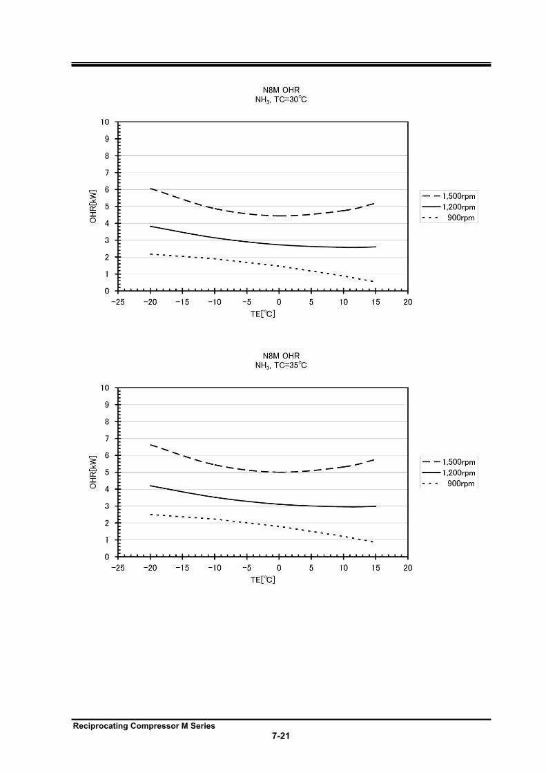
Reciprocating Compressor M Series
7-21
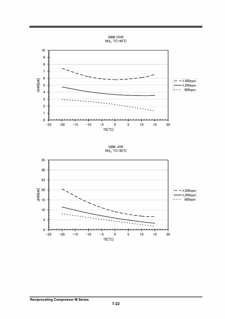
Reciprocating Compressor M Series
7-22
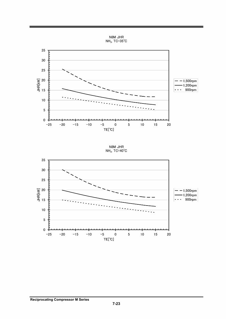
Reciprocating Compressor M Series
7-23
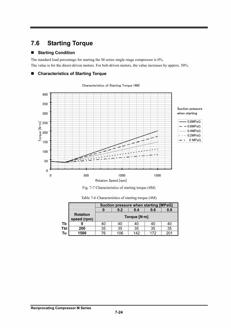
Reciprocating Compressor M Series
7-24
7.6 Starting Torque
Starting Condition
The standard load percentage for starting the M series single-stage compressor is 0%.
The value is for the direct-driven motors. For belt-driven motors, the value increases by approx. 50%.
Characteristics of Starting Torque
Characteristics of Starting Torque (4M)
0
50
100
150
200
250
300
350
400
0 500 1000 1500
Rotation Speed [rpm]
Torq
ue [
Nm
] 0.8MPaG
0.6MPaG
0.4MPaG
0.2MPaG
0 MPaG
Suction pressure
when starting
Fig. 7-7 Characteristics of starting torque (4M)
Table 7-6 Characteristics of starting torque (4M)
Suction pressure when starting [MPaG]
0 0.2 0.4 0.6 0.8
Rotation speed (rpm)
Torque [N·m]
Tb 0 40 40 40 40 40
Tbl 200 35 35 35 35 35
Tu 1500 76 106 142 172 201
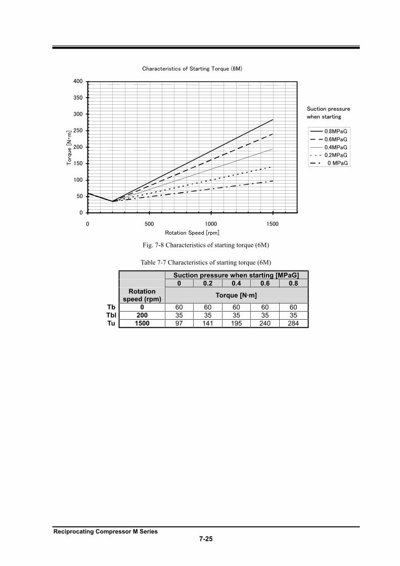
Reciprocating Compressor M Series
7-25
Rotation Speed [rpm]
Torq
ue [
Nm
]
Suction pressure
when starting
Characteristics of Starting Torque (6M)
0
50
100
150
200
250
300
350
400
0 500 1000 1500
0.8MPaG
0.6MPaG
0.4MPaG
0.2MPaG
0 MPaG
Fig. 7-8 Characteristics of starting torque (6M)
Table 7-7 Characteristics of starting torque (6M)
Suction pressure when starting [MPaG]
0 0.2 0.4 0.6 0.8
Rotation speed (rpm)
Torque [N·m]
Tb 0 60 60 60 60 60
Tbl 200 35 35 35 35 35
Tu 1500 97 141 195 240 284
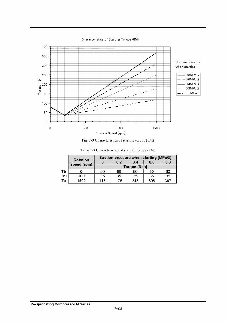
Reciprocating Compressor M Series
7-26
Torq
ue [
Nm
]
Suction pressure
when starting
Characteristics of Starting Torque (8M)
Rotation Speed [rpm]
0
50
100
150
200
250
300
350
400
0 500 1000 1500
0.8MPaG
0.6MPaG
0.4MPaG
0.2MPaG
0 MPaG
Fig. 7-9 Characteristics of starting torque (8M)
Table 7-8 Characteristics of starting torque (8M)
Rotation
speed (rpm)
Suction pressure when starting [MPaG]
0 0.2 0.4 0.6 0.8
Torque [N·m]
Tb 0 80 80 80 80 80
Tbl 200 35 35 35 35 35
Tu 1500 118 176 248 308 367
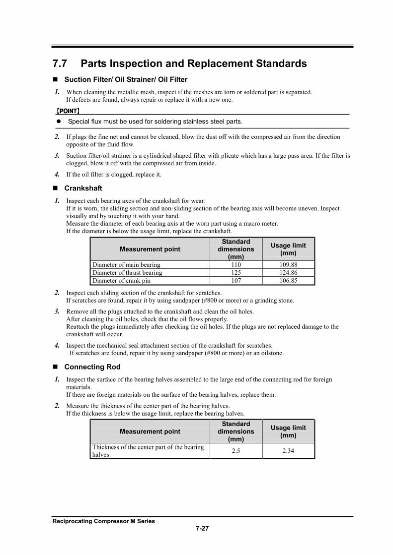
Reciprocating Compressor M Series
7-27
7.7 Parts Inspection and Replacement Standards
Suction Filter/ Oil Strainer/ Oil Filter
1. When cleaning the metallic mesh, inspect if the meshes are torn or soldered part is separated.
If defects are found, always repair or replace it with a new one.
Special flux must be used for soldering stainless steel parts.
2. If plugs the fine net and cannot be cleaned, blow the dust off with the compressed air from the direction
opposite of the fluid flow.
3. Suction filter/oil strainer is a cylindrical shaped filter with plicate which has a large pass area. If the filter is
clogged, blow it off with the compressed air from inside.
4. If the oil filter is clogged, replace it.
Crankshaft
1. Inspect each bearing axes of the crankshaft for wear.
If it is worn, the sliding section and non-sliding section of the bearing axis will become uneven. Inspect
visually and by touching it with your hand.
Measure the diameter of each bearing axis at the worn part using a macro meter.
If the diameter is below the usage limit, replace the crankshaft.
Measurement point Standard
dimensions (mm)
Usage limit (mm)
Diameter of main bearing 110 109.88
Diameter of thrust bearing 125 124.86
Diameter of crank pin 107 106.85
2. Inspect each sliding section of the crankshaft for scratches.
If scratches are found, repair it by using sandpaper (#800 or more) or a grinding stone.
3. Remove all the plugs attached to the crankshaft and clean the oil holes.
After cleaning the oil holes, check that the oil flows properly.
Reattach the plugs immediately after checking the oil holes. If the plugs are not replaced damage to the
crankshaft will occur.
4. Inspect the mechanical seal attachment section of the crankshaft for scratches.
If scratches are found, repair it by using sandpaper (#800 or more) or an oilstone.
Connecting Rod
1. Inspect the surface of the bearing halves assembled to the large end of the connecting rod for foreign
materials.
If there are foreign materials on the surface of the bearing halves, replace them.
2. Measure the thickness of the center part of the bearing halves.
If the thickness is below the usage limit, replace the bearing halves.
Measurement point Standard
dimensions (mm)
Usage limit (mm)
Thickness of the center part of the bearing
halves 2.5 2.34
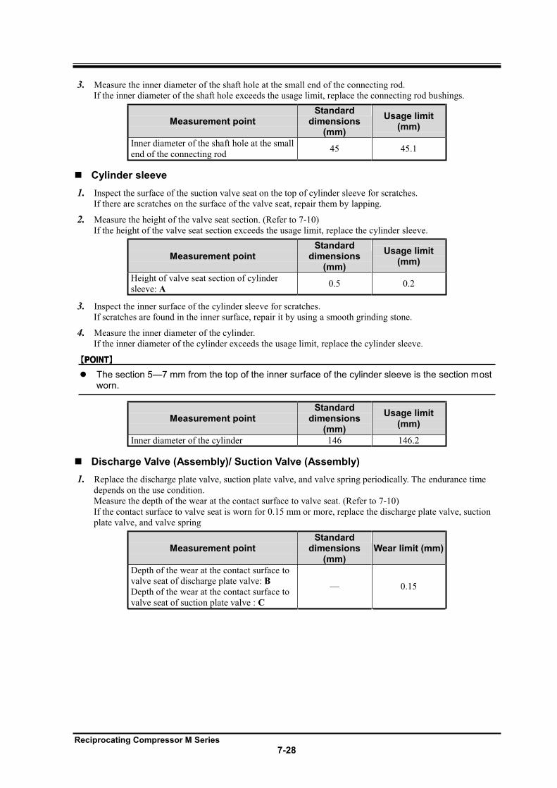
Reciprocating Compressor M Series
7-28
3. Measure the inner diameter of the shaft hole at the small end of the connecting rod.
If the inner diameter of the shaft hole exceeds the usage limit, replace the connecting rod bushings.
Measurement point Standard
dimensions (mm)
Usage limit (mm)
Inner diameter of the shaft hole at the small
end of the connecting rod 45 45.1
Cylinder sleeve
1. Inspect the surface of the suction valve seat on the top of cylinder sleeve for scratches.
If there are scratches on the surface of the valve seat, repair them by lapping.
2. Measure the height of the valve seat section. (Refer to 7-10)
If the height of the valve seat section exceeds the usage limit, replace the cylinder sleeve.
Measurement point Standard
dimensions (mm)
Usage limit (mm)
Height of valve seat section of cylinder
sleeve: A 0.5 0.2
3. Inspect the inner surface of the cylinder sleeve for scratches.
If scratches are found in the inner surface, repair it by using a smooth grinding stone.
4. Measure the inner diameter of the cylinder.
If the inner diameter of the cylinder exceeds the usage limit, replace the cylinder sleeve.
The section 5 7 mm from the top of the inner surface of the cylinder sleeve is the section most worn.
Measurement point Standard
dimensions (mm)
Usage limit (mm)
Inner diameter of the cylinder 146 146.2
Discharge Valve (Assembly)/ Suction Valve (Assembly)
1. Replace the discharge plate valve, suction plate valve, and valve spring periodically. The endurance time
depends on the use condition.
Measure the depth of the wear at the contact surface to valve seat. (Refer to 7-10)
If the contact surface to valve seat is worn for 0.15 mm or more, replace the discharge plate valve, suction
plate valve, and valve spring
Measurement point Standard
dimensions (mm)
Wear limit (mm)
Depth of the wear at the contact surface to
valve seat of discharge plate valve: B
Depth of the wear at the contact surface to
valve seat of suction plate valve : C
0.15
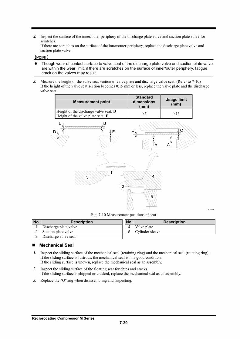
Reciprocating Compressor M Series
7-29
2. Inspect the surface of the inner/outer periphery of the discharge plate valve and suction plate valve for
scratches.
If there are scratches on the surface of the inner/outer periphery, replace the discharge plate valve and
suction plate valve.
Though wear of contact surface to valve seat of the discharge plate valve and suction plate valve are within the wear limit, if there are scratches on the surface of inner/outer periphery, fatigue crack on the valves may result.
3. Measure the height of the valve seat section of valve plate and discharge valve seat. (Refer to 7-10)
If the height of the valve seat section becomes 0.15 mm or less, replace the valve plate and the discharge
valve seat.
Measurement point Standard
dimensions (mm)
Usage limit (mm)
Height of the discharge valve seat: D
Height of the valve plate seat: E 0.5 0.15
Fig. 7-10 Measurement positions of seat
No. Description No. Description
1 Discharge plate valve 4 Valve plate
2 Suction plate valve 5 Cylinder sleeve
3 Discharge valve seat
Mechanical Seal
1. Inspect the sliding surface of the mechanical seal (retaining ring) and the mechanical seal (rotating ring).
If the sliding surface is lustrous, the mechanical seal is in a good condition.
If the sliding surface is uneven, replace the mechanical seal as an assembly.
2. Inspect the sliding surface of the floating seat for chips and cracks.
If the sliding surface is chipped or cracked, replace the mechanical seal as an assembly.
3. Replace the "O"ring when disassembling and inspecting.
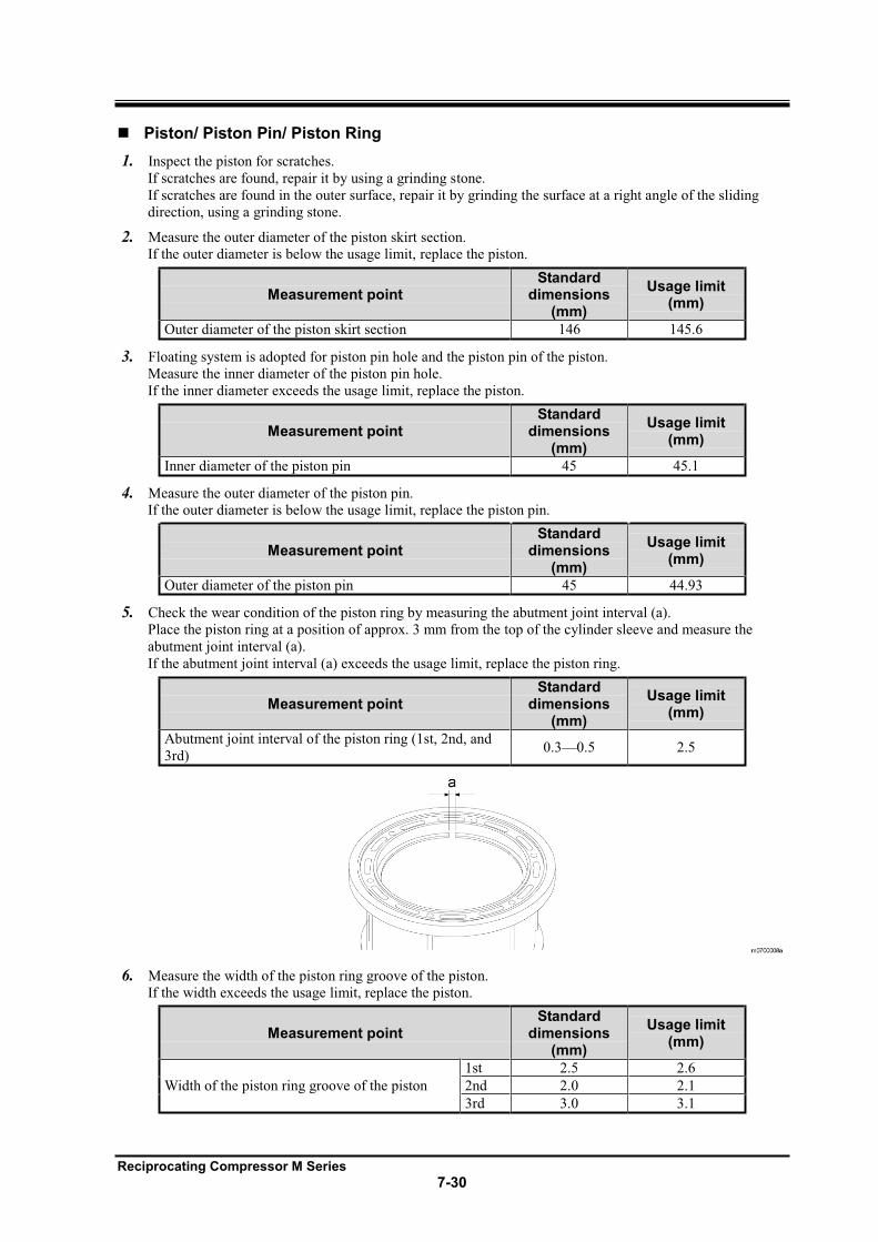
Reciprocating Compressor M Series
7-30
Piston/ Piston Pin/ Piston Ring
1. Inspect the piston for scratches.
If scratches are found, repair it by using a grinding stone.
If scratches are found in the outer surface, repair it by grinding the surface at a right angle of the sliding
direction, using a grinding stone.
2. Measure the outer diameter of the piston skirt section.
If the outer diameter is below the usage limit, replace the piston.
Measurement point Standard
dimensions (mm)
Usage limit (mm)
Outer diameter of the piston skirt section 146 145.6
3. Floating system is adopted for piston pin hole and the piston pin of the piston.
Measure the inner diameter of the piston pin hole.
If the inner diameter exceeds the usage limit, replace the piston.
Measurement point Standard
dimensions (mm)
Usage limit (mm)
Inner diameter of the piston pin 45 45.1
4. Measure the outer diameter of the piston pin.
If the outer diameter is below the usage limit, replace the piston pin.
Measurement point Standard
dimensions (mm)
Usage limit (mm)
Outer diameter of the piston pin 45 44.93
5. Check the wear condition of the piston ring by measuring the abutment joint interval (a).
Place the piston ring at a position of approx. 3 mm from the top of the cylinder sleeve and measure the
abutment joint interval (a).
If the abutment joint interval (a) exceeds the usage limit, replace the piston ring.
Measurement point Standard
dimensions (mm)
Usage limit (mm)
Abutment joint interval of the piston ring (1st, 2nd, and
3rd) 0.3 0.5 2.5
6. Measure the width of the piston ring groove of the piston.
If the width exceeds the usage limit, replace the piston.
Measurement point Standard
dimensions (mm)
Usage limit (mm)
Width of the piston ring groove of the piston
1st 2.5 2.6
2nd 2.0 2.1
3rd 3.0 3.1
Reciprocating Compressor M Series
7-31
Oil Pump
If the oil pressure is low though the oil pressure adjustment valve is closed during the operation, and if the cause
is not the clogging of the oil filter, there may be wear on the gears, metals, and shafts of the oil pump.
1. Remove the pump from the compressor, hold the shaft of the pump, and inspect the shaft for looseness by
moving it to the axial direction or right angle of the axial direction.
If the shaft is loosened, replace the oil pump as an assembly.
Main Bushing
1. Measure the inner diameter of the main bushing.
If the inner diameter exceeds the usage limit, replace the main bushing.
Measurement point Standard
dimensions (mm)
Usage limit (mm)
Inner diameter of the main bushing (seal side) 125 125.36
Inner diameter of the main bushing (pump side) 110 110.36
2. Measure the thickness of the thrust washer.
If the thickness is below the usage limit, replace the thrust washer.
Measurement point Standard
dimensions (mm)
Usage limit (mm)
Thickness of the thrust washer 3.0 2.8
Springs
Replace the discharge valve spring and suction valve spring periodically.
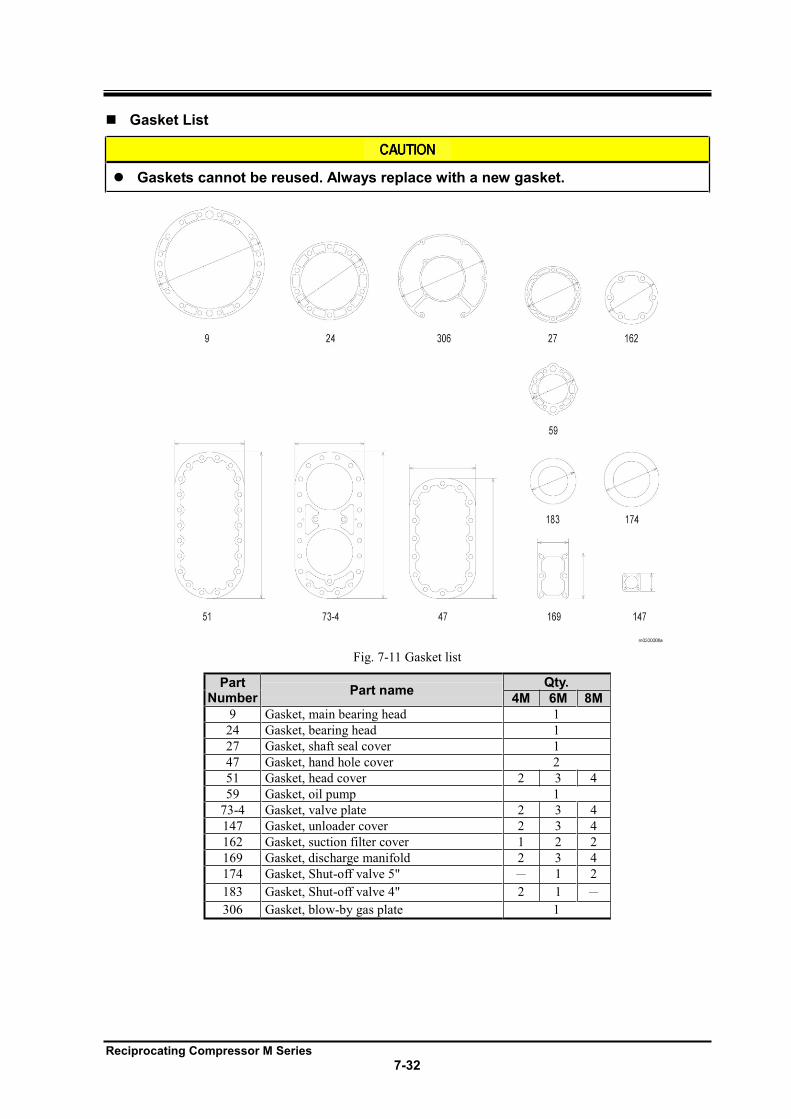
Reciprocating Compressor M Series
7-32
Gasket List
Gaskets cannot be reused. Always replace with a new gasket.
Fig. 7-11 Gasket list
Part Number
Part name Qty.
4M 6M 8M
9 Gasket, main bearing head 1
24 Gasket, bearing head 1
27 Gasket, shaft seal cover 1
47 Gasket, hand hole cover 2
51 Gasket, head cover 2 3 4
59 Gasket, oil pump 1
73-4 Gasket, valve plate 2 3 4
147 Gasket, unloader cover 2 3 4
162 Gasket, suction filter cover 1 2 2
169 Gasket, discharge manifold 2 3 4
174 Gasket, Shut-off valve 5" 1 2
183 Gasket, Shut-off valve 4" 2 1
306 Gasket, blow-by gas plate 1
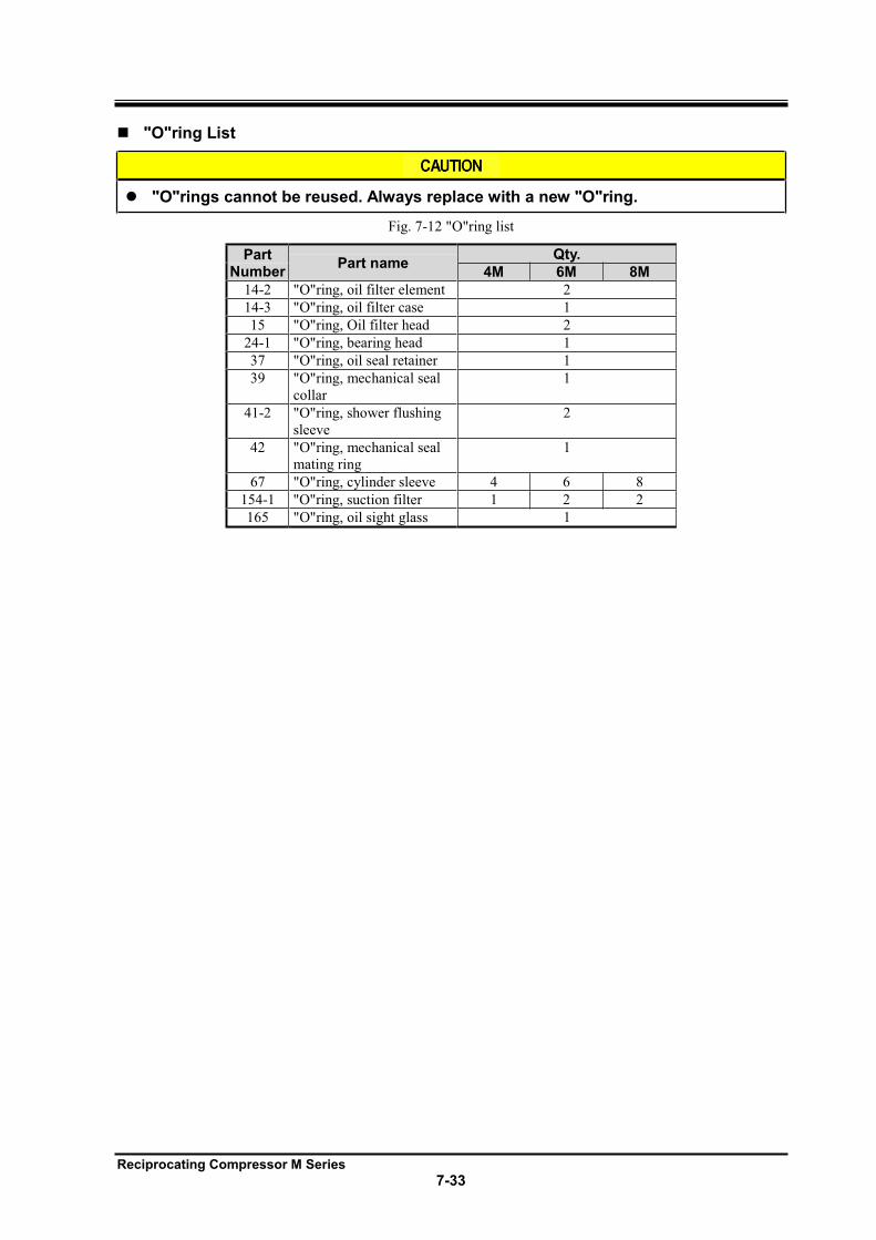
Reciprocating Compressor M Series
7-33
"O"ring List
"O"rings cannot be reused. Always replace with a new "O"ring.
Fig. 7-12 "O"ring list
Part Number
Part name Qty.
4M 6M 8M
14-2 "O"ring, oil filter element 2
14-3 "O"ring, oil filter case 1
15 "O"ring, Oil filter head 2
24-1 "O"ring, bearing head 1
37 "O"ring, oil seal retainer 1
39 "O"ring, mechanical seal
collar
1
41-2 "O"ring, shower flushing
sleeve
2
42 "O"ring, mechanical seal
mating ring
1
67 "O"ring, cylinder sleeve 4 6 8
154-1 "O"ring, suction filter 1 2 2
165 "O"ring, oil sight glass 1