ONGRUOTGA.COM GI conduit - Water-proof Flexible metallic conduit

Contents lists available at ScienceDirect
Journal of Environmental Management
journal homepage: www.elsevier.com/locate/jenvman
Research article
Recent innovations and trends in in-conduit hydropower technologies andtheir applications in water distribution systems
Mutiara Ayu Saria,∗, Mohammad Badruzzamana, Carla Cherchia, Matthew Swindleb,Newsha Ajamic, Joseph G. Jacangeloa,d
a Stantec Consulting Services Inc., 300 N. Lake Avenue, Pasadena, CA, 91101, USAbNLine Energy, Inc., 5170 Golden Foothill Parkway, El Dorado Hills, CA, 95762, USAc Stanford University, 450 Serra Mall, Stanford, CA, 94305, USAd The Johns Hopkins University- Bloomberg School of Public Health, 615 N. Wolfe Street, Baltimore, MD, 21205, USA
A R T I C L E I N F O
Keywords:In-conduit hydropowerSmall hydropowerHydro-turbineEnergy recoveryWater distribution systemsMan-made water conduits
A B S T R A C T
Water conduits have a large untapped potential to recapture energy for small hydroelectric generation, whichcan substantially reduce grid electricity consumption and/or provide renewable energy to water agencies. Overthe past decade, there has been a recent technological renaissance in off-the-shelf “water-to-wire” turbinetechnologies including reaction, impulse, and hydrokinetic turbines that target the sub 1-MW in-conduit hy-droelectric market. However, adoption of small hydropower technologies remain limited in water and waste-water utility sector, possibly due to the lack of market penetration and exposure. Moreover, information aboutnewly developed small hydropower technologies in the last 5–10 years for in-conduit applications are highlydispersed in the literature. As such, this paper is a comprehensive review on recent technological innovationsand trends in hydropower generation from water conduits. Sixteen turbine technologies (eight conventionalturbines and eight emerging turbines) are assessed and compared based on their potential benefits and chal-lenges, technology readiness levels, as well as potential sites for installations in diversion structures, potable andirrigation water distribution systems, and wastewater outfalls. Although conventional turbines are considered tobe more robust, the modular design of the newer turbines potentially offers a more cost effective solution andbetter scaling-up capability. Selected case studies on the application of conventional and new turbines for pi-pelines are also are also reviewed and discussed.
1. Introduction
Increasing population growth coupled with rising energy demandand climate change have shifted our energy focus from traditional fossilfuel to renewable energy sources. One of the renewable energy sourcesof interest currently in the United States (U.S.) is hydropower (Doig,2009). The current U.S. hydropower fleet consists of 2198 active plantswith a total capacity of 80 gigawatts (GW), accounting for approxi-mately 7% of all U.S. generating capacity (Uría-Martínez et al., 2015).In recent years, development of large hydropower (> 30MW) in-stallations has declined due to concerns associated with regulatory andpermitting challenges, land acquisition costs, and environmental im-pacts (Lisk et al., 2012). Nonetheless, according to the U.S. Departmentof Energy (DOE), hydropower growth is still expected to occur from thefollowing projects: (i) upgrades at existing hydropower plants; (ii)powering of non-powered dams; (iii) new stream-reach developments
(NSDs); (iv) new pumped-storage hydropower; and (v) powering ex-isting canals and conduits (DOE, 2016). Through its Hydropower Visioninitiative, the DOE predicted that hydropower in the U.S. will grow tonearly 150 GW by 2050 due to the implementation of these projects(DOE, 2016).
Within the above hydropower project portfolio, small hydropowersystems are increasingly being considered as an important source ofrenewable energy in the U.S. and other parts of the world. Small hy-dropower is a unit process capable of generating capacity up to 10megawatts (MW) (FERC, 2017a), typically installed in existing dams/weirs, canals, ditches, aqueducts, and pipelines. According to Paish(2002), small-hydro systems can also be further classified as mini-hydro(< 2MW), micro-hydro (< 500 kW), and pico-hydro (< 10 kW). Thetwo key advantages of using small hydropower are: (i) its higher effi-ciency compared to wind and solar (70–90% efficiency) and (ii) its lessoutput power variation (Uhunmwangho and Okedu, 2009). There are
https://doi.org/10.1016/j.jenvman.2018.08.078Received 8 May 2018; Received in revised form 26 July 2018; Accepted 20 August 2018
∗ Corresponding author.E-mail addresses: [email protected], [email protected] (M.A. Sari).
Journal of Environmental Management 228 (2018) 416–428
Available online 20 September 20180301-4797/ © 2018 Elsevier Ltd. All rights reserved.
T
currently 1640 small hydropower plants with a combined generatingcapacity of approximately 3670MW in the U.S (Johnson andHadjerioua, 2015). However, there is a tremendous untapped potentialof small hydropower installations. For instance, in the state of Cali-fornia alone, there is 2467MW undeveloped small hydropower poten-tial (Park, 2006). Although the greatest potential lies in natural watercourses (2189MW), the same study also estimated substantial hydro-power potential in man-made water conduits (255–278MW).
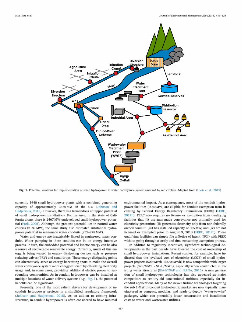
Water and energy are inextricably linked in engineered water con-duits. Water pumping in these conduits can be an energy intensiveprocess. In turn, the embedded potential and kinetic energy can be alsoa source of recoverable renewable energy. Currently, much of this en-ergy is being wasted in energy dissipating devices such as pressurereducing valves (PRV) and canal drops. These energy dissipating pointscan alternatively serve as energy harvesting spots to make the overallwater conveyance system more energy-efficient by off-setting electricityusage and, in some cases, providing additional electric power to sur-rounding communities. As in-conduit hydropower can be installed atmultiple locations of water delivery systems (e.g., Fig. 1), the potentialbenefits can be significant.
Presently, one of the most salient drivers for development of in-conduit hydropower projects is a simplified regulatory framework(Johnson and Hadjerioua, 2015). As an add-on to existing infra-structure, in-conduit hydropower is often considered to have minimal
environmental impact. As a consequence, most of the conduit hydro-power facilities (≤40MW) are eligible for conduit exemption from li-censing by Federal Energy Regulatory Commission (FERC) (FERC,2017b). FERC also requires no license or exemption from qualifyingfacilities that (i) use man-made conveyance not primarily used forelectricity generation; (ii) generates electricity only from non-federallyowned conduit; (iii) has installed capacity of ≤5MW; and (iv) are notlicensed or exempted prior to August 9, 2013 (FERC, 2017c). Thesequalifying facilities can simply file a Notice of Intent (NOI) with FERCwithout going through a costly and time-consuming exemption process.
In addition to regulatory incentives, significant technological de-velopments in the past decade have lowered the cost of ownership ofsmall hydropower installations. Recent studies, for example, have in-dicated that the levelized cost of electricity (LCOE) of small hydro-power projects ($20/MWh - $270/MWh) is now comparable with largerprojects ($20/MWh - $190/MWh), especially when constructed in ex-isting water structures (IEA-ETSAP and IRENA, 2015). A new genera-tion of small hydropower technologies has also appeared as majorcompetitors to century-old conventional turbines, especially for in-conduit applications. Many of the newer turbine technologies targetingthe sub 1-MW in-conduit hydroelectric market are now typically man-ufactured as compact, modular, and ready-to-deploy “water-to-wire”packages, which can potentially lower construction and installationcosts to water and wastewater utilities.
Fig. 1. Potential locations for implementation of small hydropower in water conveyance system (marked by red circles). Adapted from (Loots et al., 2015).
M.A. Sari et al. Journal of Environmental Management 228 (2018) 416–428
417
Despite the above regulatory incentives and technological ad-vancements, a comprehensive review of the state-of-the-art technolo-gies for in-conduit is lacking in the literature. Unlike large hydropower,small hydropower installations generally are comprised of a largevariety of designs, layouts, equipment and materials (IEA-ETSAP andIRENA, 2015), presenting a substantial number of options to waterpurveyors. To date, several reports and peer-reviewed publicationshave compiled information regarding the technologies for small hy-dropower systems (McKinney et al., 1983; Paish, 2002; CETC, 2004;Johnson et al., 2015; Loots et al., 2015). However, the technologiesdiscussed are generally outdated and lacking in specificity on in-con-duit hydropower applications. Accordingly, the main objective of thispaper is to provide a comprehensive literature review on recent tech-nological innovations and trends in hydropower generation from waterconduits. The various technologies are assessed and compared based ontheir potential benefits and challenges, technology readiness levels, aswell as potential sites for installations in diversion structures, potableand irrigation water distribution supply systems, and wastewater out-falls. Selected case studies on existing pipeline projects along with thelessons learned are reviewed and discussed.
2. Current hydropower technologies for conduit applications
A basic hydropower unit consists of a turbine and a generator.Despite their variety, most turbines, based on their main operatingprinciples, can be categorized as either a reaction, impulse, or hydro-kinetic turbines. A reaction turbine, such as Francis and Kaplan tur-bines, uses both pressure and movement of the water to generate anupward hydrodynamic force to rotate the runner blades. An impulseturbine, such as Pelton, Turgo, and Crossflow turbines, uses runnersthat are rotated by water jets at high velocities. Reaction turbines aregenerally more applicable to low head systems, whereas impulse tur-bines are more suitable for medium-high head applications. However,there is considerable overlap in their practical applications (McKinneyet al., 1983). Some newer generation of impulse turbines, for example,can also now handle low head systems such as hydrodynamic screwturbines, Natel Energy's hydroEngine®, modular water wheel, etc. Inaddition to reaction and impulse turbines, there is a growing interest inthe development and installation of the less common hydrokineticturbines, which generate power by harnessing the kinetic energy ofmoving water. Commercially available hydrokinetic units are typically
installed in rivers, natural and man-made canals, and marine environ-ments.
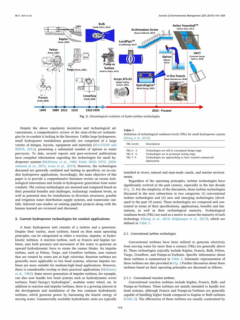
Regardless of the operating principles, turbine technologies havesignificantly evolved in the past century, especially in the last decade(Fig. 2). For the simplicity of the discussion, these turbine technologiesdiscussed in the next subsections in two categories: (i) conventionalturbine technologies and (ii) new and emerging technologies (devel-oped in the past 10 years). These technologies are compared and con-trasted in terms of their specifications, applications, benefits and lim-itations, as well as their technological maturity. Technologicalreadiness levels (TRL) are used as a metric to assess the maturity of eachtechnology (Zhang et al., 2012; Delplanque et al., 2017), which aredefined in Table 1.
2.1. Conventional turbine technologies
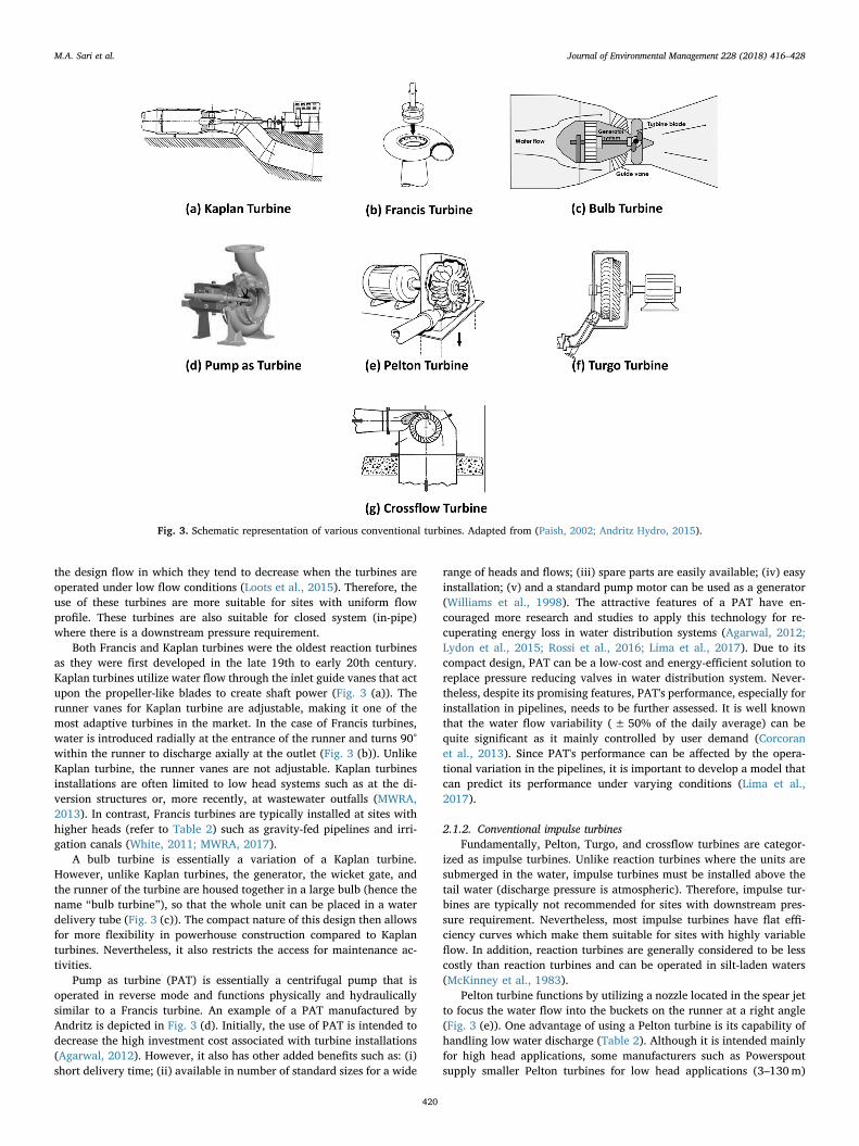
Conventional turbines have been utilized to generate electricityfrom moving water for more than a century (TRLs are generally above8). These technologies typically include Kaplan, Francis, Bulb, Pelton,Turgo, Crossflow, and Pumps-as-Turbines. Specific information aboutthese turbines is summarized in Table 2. Schematic representation ofthese turbines are also provided in Fig. 3.Further discussion about theseturbines based on their operating principles are discussed as follows.
2.1.1. Conventional reaction turbinesConventional reaction turbines include Kaplan, Francis, Bulb, and
Pumps-as-Turbines. These turbines are mainly intended to handle lowhead systems, although Francis and Pumps-as-Turbines are generallycapable of handling higher heads compared to Kaplan or Bulb turbines(Table 2). The efficiencies of these turbines are usually constrained by
Fig. 2. Chronological evolution of hydro-turbine technologies.
Table 1Definition of technological readiness levels (TRL) for small hydropower system(Zhang et al., 2012).
TRL Levels Descriptions
TRL 0 - 3 Technologies are still in conceptual design stageTRL 4 - 6 Technologies are in prototype testing stageTRL 7- 9 Technologies are approaching or have reached commercial
deployment
M.A. Sari et al. Journal of Environmental Management 228 (2018) 416–428
418

Table2
List
ofco
nven
tion
alturbines
forsm
allhy
drop
ower.
Tech
nology
Type
Ran
geof
net
head
(m)
Ran
geof
water
flow
(m3/s)
Cap
acity(kW)
TRL
Bene
fits
Limitations
App
lications
Man
ufacturer
Location
Refs.
US
Non
US
Kap
lan
Reaction
≤10
–40
2.8–
3030
0-15
,000
9-Highlyad
justab
le-Higheffi
cien
cy-Can
workat
low
head
-Relativelyexpe
nsive
-Needhe
avydu
tyge
nerator
-Needve
rylargeflow
rate
-Dam
spillway
-Ex
isting
cana
ls/
dive
rsion
-Lo
whe
adcana
l
Can
yonHyd
ro,
Ossbe
rger,M
avel,
Voith
Hyd
ro,A
ndritz
✓✓
(Joh
nson
etal.,20
15)
(Bob
rowicz,
2006
)(V
oith
Hyd
ro,2
015)
Fran
cis
Reaction
≤50
–110
0.4–
2330
0-35
,000
9-Reliablean
dsimple
-Adjustable
-Sm
allrunn
eran
dge
nerator
-Sm
allch
ange
ineffi
cien
cy
-Veryna
rrow
operating
rang
e-Diffi
cultto
inspect
-Pron
eto
cavitation
-Water
hammer
effects
-Dam
-Irriga
tion
cana
lsCan
yonHyd
ro,
Gilk
es,M
avel,V
oith
Hyd
ro,A
ndritz
✓✓
(Joh
nson
etal.,20
15)
(Bob
rowicz,
2006
)(V
oith
Hyd
ro,2
015)
Bulb
Reaction
2–30
NA
1000
–10,00
09
-Com
pact
-Nopo
werho
usene
eded
-Diffi
cultto
access
for
service
-Req
uire
specialair
circulationan
dco
oling
withinthebu
lb
-Can
als
-Pipe
lines
Ossbe
rger,V
oith
Hyd
ro,A
ndritz
✓✓
(Voith
Hyd
ro,2
015)
SmallPe
lton
Impu
lse
3–13
00.00
8–0.01
0.1–
1.6(single
unit)
8-Sm
all
-Relativelych
eap
-Can
hand
lelower
head
than
largepe
lton
Mustbe
installedat
ahigh
erleve
ltha
nwater
surface(m
ust
build
platform
toplacethe
turbine)
Ove
rflow
pipe
alon
gsideape
nstock
PowerSp
out
✓✓
(Pow
erSp
out,20
14)
Pelton (c
onve
ntiona
l)Im
pulse
100–
1300
0.00
5–2.1
300-35
,000
9-Can
bemou
nted
onbo
thho
rizo
ntal
and
vertical
shafts
-Highov
eralleffi
cien
cy-Can
beop
erated
insilted
water
-Has
flat
efficien
cycu
rve
-Effi
cien
cyde
creasesov
ertime
-La
rge-sizedco
mpo
nents
-Variation
inop
erating
head
isdifficu
ltto
control
Irriga
tion
ditche
sCan
yonHyd
ro,P
ower
Spou
t,Gilk
es,Mav
el,
Voith
Hyd
ro,A
ndritz
✓✓
(Joh
nson
etal.,20
15)
(Bob
rowicz,
2006
)(V
oith
Hyd
ro,2
015)
Turgo
Impu
lse
10–5
000.03
–10
upto
10,000
9-Simpleto
man
ufacture,
cheap
-Has
ago
odeffi
cien
cyan
drelia
bility
-Has
high
erspecific
speed
-Can
hand
lehigh
erflow
sthan
Pelton
turbine
-Req
uiresmorehe
adhe
ight
than
othe
rturbines
-Has
tobe
conn
ectedto
apipe
orpe
nstock
tofunc
tion
-Run
-of-rive
rhy
drosche
mes
-Aqu
educ
ts
Gilk
es,P
owerSp
out
✓✓
(Bob
rowicz,
2006
)(G
ilkes,20
03)
Crossflow
(Ban
ki)
Impu
lse
5.5–
650
0.04
–510
0–10
009
-Su
itab
leforseason
ally
fluc
tuatingflow
sources
-One
turbinecan
operateov
eralarge
rang
eof
flow
-Designe
dforself-
cleaning
-Req
uiresdrafttube
tocapturethewater
power
-Fo
rave
ryna
rrow
turbine,
theloss
ofeffi
cien
cyis
quitelarge
-Siph
onpe
nstock
-Diversion
tohy
drop
ower
-Aqu
educ
ts
Can
yonHyd
ro,
Ossbe
rger
✓✓
(Joh
nson
etal.,20
15)
(Bob
rowicz,
2006
)
Pumpas
turbine
Cen
trifug
alpu
mp
upto
800.8–
620
–750
8-Lo
wco
st-Ava
ilablein
stan
dard
sizes
-Ea
syinstallation
-Can
usepu
mpmotor
asge
nerator
-Itspe
rforman
ceisdifficu
ltto
pred
ict
-Gen
erally
requ
ires
stab
lepressure
andflow
-Irriga
tion
chan
nels
-Aqu
educ
ts-Pipe
lines
Ren
tricity,
Corne
llpu
mp,
And
ritz,K
SB✓
✓(Bob
rowicz,
2006
)(A
ndritz
Hyd
ro,
2015
)
M.A. Sari et al. Journal of Environmental Management 228 (2018) 416–428
419
the design flow in which they tend to decrease when the turbines areoperated under low flow conditions (Loots et al., 2015). Therefore, theuse of these turbines are more suitable for sites with uniform flowprofile. These turbines are also suitable for closed system (in-pipe)where there is a downstream pressure requirement.
Both Francis and Kaplan turbines were the oldest reaction turbinesas they were first developed in the late 19th to early 20th century.Kaplan turbines utilize water flow through the inlet guide vanes that actupon the propeller-like blades to create shaft power (Fig. 3 (a)). Therunner vanes for Kaplan turbine are adjustable, making it one of themost adaptive turbines in the market. In the case of Francis turbines,water is introduced radially at the entrance of the runner and turns 90°within the runner to discharge axially at the outlet (Fig. 3 (b)). UnlikeKaplan turbine, the runner vanes are not adjustable. Kaplan turbinesinstallations are often limited to low head systems such as at the di-version structures or, more recently, at wastewater outfalls (MWRA,2013). In contrast, Francis turbines are typically installed at sites withhigher heads (refer to Table 2) such as gravity-fed pipelines and irri-gation canals (White, 2011; MWRA, 2017).
A bulb turbine is essentially a variation of a Kaplan turbine.However, unlike Kaplan turbines, the generator, the wicket gate, andthe runner of the turbine are housed together in a large bulb (hence thename “bulb turbine”), so that the whole unit can be placed in a waterdelivery tube (Fig. 3 (c)). The compact nature of this design then allowsfor more flexibility in powerhouse construction compared to Kaplanturbines. Nevertheless, it also restricts the access for maintenance ac-tivities.
Pump as turbine (PAT) is essentially a centrifugal pump that isoperated in reverse mode and functions physically and hydraulicallysimilar to a Francis turbine. An example of a PAT manufactured byAndritz is depicted in Fig. 3 (d). Initially, the use of PAT is intended todecrease the high investment cost associated with turbine installations(Agarwal, 2012). However, it also has other added benefits such as: (i)short delivery time; (ii) available in number of standard sizes for a wide
range of heads and flows; (iii) spare parts are easily available; (iv) easyinstallation; (v) and a standard pump motor can be used as a generator(Williams et al., 1998). The attractive features of a PAT have en-couraged more research and studies to apply this technology for re-cuperating energy loss in water distribution systems (Agarwal, 2012;Lydon et al., 2015; Rossi et al., 2016; Lima et al., 2017). Due to itscompact design, PAT can be a low-cost and energy-efficient solution toreplace pressure reducing valves in water distribution system. Never-theless, despite its promising features, PAT's performance, especially forinstallation in pipelines, needs to be further assessed. It is well knownthat the water flow variability (± 50% of the daily average) can bequite significant as it mainly controlled by user demand (Corcoranet al., 2013). Since PAT's performance can be affected by the opera-tional variation in the pipelines, it is important to develop a model thatcan predict its performance under varying conditions (Lima et al.,2017).
2.1.2. Conventional impulse turbinesFundamentally, Pelton, Turgo, and crossflow turbines are categor-
ized as impulse turbines. Unlike reaction turbines where the units aresubmerged in the water, impulse turbines must be installed above thetail water (discharge pressure is atmospheric). Therefore, impulse tur-bines are typically not recommended for sites with downstream pres-sure requirement. Nevertheless, most impulse turbines have flat effi-ciency curves which make them suitable for sites with highly variableflow. In addition, reaction turbines are generally considered to be lesscostly than reaction turbines and can be operated in silt-laden waters(McKinney et al., 1983).
Pelton turbine functions by utilizing a nozzle located in the spear jetto focus the water flow into the buckets on the runner at a right angle(Fig. 3 (e)). One advantage of using a Pelton turbine is its capability ofhandling low water discharge (Table 2). Although it is intended mainlyfor high head applications, some manufacturers such as Powerspoutsupply smaller Pelton turbines for low head applications (3–130m)
Fig. 3. Schematic representation of various conventional turbines. Adapted from (Paish, 2002; Andritz Hydro, 2015).
M.A. Sari et al. Journal of Environmental Management 228 (2018) 416–428
420

Table3
List
ofad
vanc
edturbines
curren
tlyon
themarke
t.
Tech
nology
Type
Ran
geof
head
(m)
Ran
geof
water
discha
rge(m
3/
s)
Cap
acity/
unit(kW)
TRL
Bene
fits
Limitations
App
lications
Man
ufacturer
Location
Refs.
US
Non
US
Inlin
eHyd
roTu
rbine
Inlin
eFran
cis
turbine
8–17
40.03
–2Upto
2000
8In-pipeap
plication
Bulkierthan
LucidP
ipe
In-pipe
Can
yonHyd
ro/
Soar
Hyd
ro✓
(SOARHyd
ropo
wer,
2016
)TM
Mod
ular
Micro
Turbine
Siph
onturbine
1.5–
60.14
–55–
160
8Nopo
werho
userequ
ired
-Onlyforspecific
use
-Req
uiresadraft
tube
Divided
cana
lsMav
el✓
✓(M
avel,2
015)
AmjetATS
-63
Kap
lanturbine/
gene
rator
combina
tion
1.5–
12.8
9–26
100–
2500
4-Nopo
werho
use
requ
ired
-Lo
wer
installation
cost
-Widerang
eof
applications
Designstill
unde
rev
alua
tion
-Can
als
-Pipe
lines
-Non
-pow
ered
dams
AmjetTu
rbine
System
s–
–(A
mjetTu
rbine
System
,201
5)
HeliosPo
werba
ll™Mod
ular
water
whe
elNA
0.06
–0.17
(min)
0.1–
0.5
8-Mod
ular
design
-Can
cope
withha
rsh
cond
itions
-En
vironm
entally
friend
ly
Smallcapa
city
-Can
als
-Con
crete-lin
ech
utes
-Wastewater
outlet
HelioAltas
Corp.
✓(H
elio
Altas,20
17)
Archimed
ean
hydrod
ynam
icscrews
Rev
ersedscrew
pump
1–10
0.1–
155–
500
8-Goo
dop
erating
efficien
cy-Lo
nglifebe
arings
-Rob
ust,ha
rd-w
earing
andrelia
ble
-Deb
ristolerant
-Fish
friend
ly
-Bu
lkyan
dhe
avy
-Con
structionmay
beco
mplicated
-Sm
allerda
ms
-Diversion
structures
-Irriga
tion
weirs
-Se
wag
eplan
tsou
tlet
Reh
art,
Land
ustrie,S
paan
sBa
bcoc
k
–✓
(Lan
dustrie,
2015
)
Line
arPe
lton
hydroE
ngine®
Aseries
ofpe
lton
bucketson
linear
powertrain
3–20
0.5–
1425
–100
07
-Lo
wco
st-Ea
syto
install
-Nocavitation
-Le
ssexcava
tion
cost
-Req
uiresape
nstock
-Not
suitab
lefor
pipe
lines
-Run
ofrive
rsche
mes
-Irriga
tion
cana
ls-Ove
rtailw
ater
-In
dam
orweir
Natel
Energy
✓(N
atel
Energy
,201
6b)
LucidP
ipe™
Sphe
ricalin-line
turbine
NA
1–5.6(m
in)
18–1
007
-Noby
pass
requ
ired
-Noim
pact
onwater
deliv
ery
-Ava
ilablein
man
ysizes
1034
kPa(150
psi)max
working
pressure
In-pipeinstallation
sLu
cidE
nergy
✓(Luc
idEn
ergy
,201
7)
VerticalAxis
Hyd
rokine
tic
Turbine
Hyd
rokine
ticturbine
NA
NA
256
-Ba
sedon
lyon
flow
,no
the
ad-Doe
sno
tdisrup
ten
vironm
ent
-Mod
ular
Fairly
new
tech
nology
-Irriga
tion
cana
ls-Aqu
educ
ts
Instream
Energy
System
s,Em
rgy
✓(Instream
Energy
System
s,20
14;
Emrgy,
2018
)
M.A. Sari et al. Journal of Environmental Management 228 (2018) 416–428
421

(PowerSpout, 2014). Pelton turbines are commonly installed in irriga-tion ditches.
The operating principle and the design of Turgo turbine is similarwith that of Pelton turbine. However, the water jet strikes the center ofthe buckets on the runner at an acute angle instead of at a right angle(Fig. 3 (f)). As shown in Table 2, Turgo turbine can also generallyhandle lower heads and higher flow rates compared to Pelton turbine.In addition, its speed is about twice that of Pelton turbine for the samehead and runner diameter (McKinney et al., 1983). Turgo turbines arecommonly seen in run-of-river hydro schemes and aqueducts.
Similar to a Turgo turbine, a crossflow turbine (or Banki turbine) isdesigned to handle higher water flow and lower heads than Peltonturbines (McKinney et al., 1983). The crossflow turbine utilizes a cy-lindrical runner with a solid disk at each end and curved blades joiningthe two disks. As can be seen from Fig. 3 (g), the water jet enters fromthe top part of the runner, passing through the gutter-shaped bladestwice before emerging on the far side of the runner. The gutter-likeshape of the blades allow the water to transfer some of its momentumon each passage before falling away with little residual energy (Paish,2002). The cylindrical shape of the runner and inlet nozzle increases theturbine's flow capacity, allowing the turbine to accommodate lowerheads. However, the efficiency of this crossflow turbine is quite low dueto its complex flow path (McKinney et al., 1983). Similar to Turgoturbines, crossflow turbines are commonly installed in aqueducts, di-version structures, or siphon penstocks.
2.2. New turbine technologies
Although the design of conventional turbines are quite robust, im-provements on the turbine performance are necessary to ensure a betterefficiency and possibly at a lower cost. Several companies have recentlyoffered novel turbine technologies that can open up a wider applicationfor potential site development that has not been considered previously.The description and the current development state of these new tech-nologies according to their operating principles along with their ben-efits and limitations as well as TRLs are discussed below. The in-formation is also summarized in Table 3.
2.2.1. Advanced reaction turbinesMost of the new reaction turbines are essentially variations from
conventional reaction turbines such as Kaplan (or propeller-type) orFrancis turbines. However, several modifications have been made inorder to make their implementation more economically-viable forparticular application. For example, SOAR Hydropower's ILT series(now part of Canyon Hydro) is a Francis turbine that is being modifiedfor in-line applications (pipe diameter between 4″-24″) (SOARHydropower, 2016). The unit is commonly installed in parallel withexisting PRVs with installed capacity up to 1MW.
Development of a compact and modular turbine has also been therecent trend in turbine technologies. This turbine/generator designrequires minimum powerhouse construction, thereby lowering in-stallation cost significantly. Two examples of modular reaction turbinesinclude siphon turbines and axial-type propeller turbine/generator unit.A siphon turbine utilizes siphon technology to capture energy of waterusing a Kaplan-type runner with four manually adjustable blades(Fig. 4). One example of a siphon turbine is TM Modular Micro Turbineby Mavel (2015). Although 65 units have been installed globally, thefirst U.S. installation was only implemented in 2015. Located in Idaho,the project site is a diversion structure that divides the flow of the maincanal into three branch canals. Eight modular turbines with a totalcapacity of 1224 kW were then installed in these divided canals.
Axial-type propeller turbine/generator unit utilizes propeller tur-bine technology in an axial flow compact composite design. The unitcan be applied in wide range of applications such as irrigation canaldrops, in-pipe installations to replace PRVs, non-powered low headdams, etc. Examples of units currently available in the market include
Hydromatrix turbine by Andritz Hydro (Andritz Hydro, 2014),StreamDiver turbine by Voith Hydro (Voith Hydro, 2015), and AmjetATS-63 turbine by Amjet Turbine System (Amjet Turbine System,2015).
2.2.2. Advanced impulse turbinesThe development of advanced impulse turbines has been more rapid
than reaction turbines over the past decade since they are generally lessexpensive to manufacture and easier to maintain. Similar with reactionturbines, modularity is still the key element in the design of new im-pulse turbines. The examples of new generation impulse turbines in-clude modular water wheel (Helios Powerball™), Archimedean screwturbine, hydroEngine®, and LucidPipe™.
Water wheel has been utilized for centuries to generate power atlow cost. However, conventional water wheel is considered to be lessefficient than other turbines designed specifically for electricity pro-duction. Therefore, modification is necessary for the waterwheel inorder to generate enough power for commercial use. The modificationcan include incorporation of a high-ratio gear box and specializedcontrol to increase the speed (NorthWestern Energy, 2016). A newgeneration of water wheel is smaller in size, more modular, and can beemployed in existing infrastructure such as canals, concrete-linedchutes, industrial water loops, etc.
The Helios Powerball™ by HelioAltas Corp. is one example of a newgeneration of water wheel turbine (Helio Altas, 2017) (Fig. 5). Therange of power output is between 100 and 500W; however, the unit canbe connected into an array, creating a new system called HydroFarms™,allowing the power output to be scaled up. All of the generation com-ponents are also contained within the shell of the unit, making it thefirst modular water wheel available in the market. The unit can alsocope well with debris, silts, very low flow conditions, as well as var-iations in temperature and weather conditions.
There is an increasing interest in the installation of Archimedeanhydrodynamic screw turbines for conduit applications, especially atweirs or outlets of sewage treatment. The Archimedean screw turbine,uses the principle of the Archimedean screw pump in reverse, utilizingthe hydrostatic pressure difference across the blades. As can be seenfrom Fig. 6, the water enters the screw at the top and the weight of thewater pushes the helical flights, causing the screw to rotate as waterfalls to the lower level. The rotational energy produced can be extracted
Fig. 4. TM Modular Micro Turbine (siphon turbine). Adapted from (Mavel,2015).
M.A. Sari et al. Journal of Environmental Management 228 (2018) 416–428
422

by an electrical generator. The screw turbine is commonly used for lowhead and high flow applications, such as existing dam or weir andoutlets of sewage treatment. One notable advantage of using an Ar-chimedean screw turbine is that it provides safe fish passage comparedto other turbines.
The HydroEngine® turbine by Natel Energy is one example of im-pulse-style turbine that can handle lower head systems with wide rangeof flows. As seen in Fig. 7(a), the first generation of HydroEngine®
turbine (Schneider Linear HydroEngine® (SLH)) consists of two parallelshafts connected with a belt of blades moving in a linear racetrack-likepath between the shafts. The unit was designed to be used in similarcircumstances as a Kaplan turbine such as at small dam walls or canaldrop. However, unlike Kaplan turbine, the unit can be installed abovethe tail water which consequently reduces excavation costs and un-certainty.
Several modifications were made to the original turbine and thelatest version, Linear Pelton (LP) HydroEngine®, is currently availablein the market. Unlike its predecessor, the LP version utilizes a series ofPelton-style buckets on a linear powertrain. As seen in Fig. 7(b) waterenters the engine through a rectangular nozzle which converts pressureto velocity and directs the jet of water towards a series of buckets. Thetransfer of momentum from water to bucket is then harnessed as useful
torque that turns the shaft.LucidPipe™ is an inline spherical turbine that can be installed di-
rectly in the primary conduit of a pressurized system (LucidEnergy,2017). The installations of conventional hydropower technologies thathave been adapted for in-pipe applications usually require a bypassloop due to significant loss in pressure (up to 95%). LucidPipe™ offers asolution to this critical problem as it can operate in wide range ofpressure/flows without needing a bypass. It also comes with a widerange of pipe sizes (0.61–1.52m). Its power capacity depends on thepipe diameter and the range is about 18–100 kW per unit withminimum flow of 1–5.6 m3/s. The system has already been tested andcertified by NSF International to NSF/ANSI Standard 61 for use in po-table water systems as well as agricultural, industrial, and wastewaterpipeline systems (LucidEnergy, 2015a). The schematic representationof LucidPipe™ turbine is depicted in Fig. 8. LucidPipe™ units are cur-rently installed for Riverside Public Utilities (Riverside, California) andPortland Water Bureau (Portland, Oregon).
Fig. 5. Schematic representation of Helios Powerball™. Adapted from (HelioAltas, 2017).
Fig. 6. Schematic representation of Archimedean screw turbine. Adapted from (Spaans Babcock, 2017).
Fig. 7. Schematic representation of Schneider Linear HydroEngine® (a) andLinear Pelton hydroEngine®(b). Adapted from (Natel Energy, 2016a, 2017).
M.A. Sari et al. Journal of Environmental Management 228 (2018) 416–428
423

2.2.3. Hydrokinetic turbinesHydrokinetic turbines generate electricity by harnessing the kinetic
energy of moving water instead of the potential energy due to hydraulichead. Instream Energy Systems is one of the pioneers in development ofnovel hydrokinetic turbine (Fig. 9). The unit is designed to produceenergy without disruption the environment at a lower cost and reducedregulatory issues (Instream Energy Systems, 2014). The rated capacityfor each unit is 25 kW and its application is suitable for man-madewaterways such as irrigation canals and aqueducts.
Most of the current VAHT units are installed in natural waterwayssuch as dam discharge channels (The Duncan Dam near Kaslo, BritishColumbia, Canada), rivers (SEENEOH Bordeaux Tidal Estuarine site inFrance and the living bridge project in New Hampshire, USA), and
marine environments (Morlais demonstration zone in Anglesey, Wales,UK) (Instream Energy Systems, 2017). However, in 2013, InstreamEnergy Systems along with USBR installed the unit in man-made con-duit near Yakima, Washington (Roza canal). One of the main objectivesof the project was to show that the unit is not detrimental to existinginfrastructure and the surrounding environment.
3. Comparisons of conventional and new turbine technologies
Based on the previous discussion, comparisons between conven-tional and new technologies are summarized in Table 4 and discuss asfollows.
Conventional turbines are generally very robust and able to operatefor decades. For example, Francis and Pelton turbines employed in ir-rigation canals in Hood River, Oregon, have been operating for almostthree decades (Perkins, 2013). Since most of these technologies havebeen proven to perform well over decades, they are usually categorizedas TRL 9, indicating that these technologies are already mature (Zhanget al., 2012; Delplanque et al., 2017). In contrast, most of the newertechnologies have TRLs ≤8 as their installation periods are still rela-tively short. In addition, some of the technologies are also still in pro-totype stage (TRL 4–6).
Due to their high maturity level, there are abundant informationabout conventional technologies as well as their case studies that can beeasily used as references for new developers. In contrast, more time isneeded to determine the robustness of new turbine technologies as mostof the current units have been operating less than 10 years. Due to theinadequate testing period, there is still a lack of information regardingthe effectiveness of the units, the installations (engineering and con-struction works), as well as the cost components. In addition, the de-signs are still continuously being updated. For example, the first gen-eration of hydroEngine® by Natel Energy (the Schneider Linear model)has been recently replaced by the Linear Pelton (LP) model (NatelEnergy, 2017). While some information is available about the in-stallations of the SLH model, there is limited information about the newmodel.
Nevertheless, the use of conventional turbines mostly require con-struction of a powerhouse. A recent study by Oak Ridge NationalLaboratory observed that the powerhouse construction accounts for alarge portion of the initial capital cost (Zhang et al., 2012). Conven-tional turbines are also considered to be less efficient and, in somecases, can be energy-intensive when a large generator is needed. Mostof the new turbine technologies offer a cost-effective solution to thisproblem by combining the turbine and generator into one unit (i.e.modular system), thereby minimizing the need to build a powerhouse.The modular design also utilizes a small generator; therefore, less en-ergy is required. In addition, the modular design also allows the unit tobe easily scalable, depending on the site characteristics and the powerdemand. For example, multiple hydrokinetic turbine can be installed ina large canal in multiple configurations for maximum power production(Instream Energy Systems, 2014; Emrgy, 2018). Some hydrokineticturbine can also be stacked vertically for larger cross-sectional flows(Emrgy, 2018).
In regards to equipment cost, the comparison between conventionaland new technologies are not straight forward as the turbine costsometimes vary depending on the site and turbine characteristics (Okot,2013). For example, a recent study estimated that the Archimedeanscrew turbine has a higher hydromechanical and electrical cost com-pared to Kaplan turbine for wastewater output application (Ak et al.,2017). However, the total cost of installing Kaplan turbine is actuallyhigher than Archimedean screw turbine due to its higher cost for intakestructure and power house construction. The modular design of thescrew turbine also allows for lower powerhouse construction cost,which eventually helps in reducing the total installation cost.
Fig. 8. LucidPipe™ spherical in-line turbine. Adapted from (LucidEnergy,2017).
Fig. 9. Schematic representation of Vertical Axis Hydrokinetic Turbine (VAHT).Adapted from (Instream Energy Systems, 2014).
M.A. Sari et al. Journal of Environmental Management 228 (2018) 416–428
424
4. Site specific application of technologies
Given the large variety of options, water and wastewater utilitiesmust carefully evaluate hydropower turbines available on the marketbased on their site-specific applications. Potential conduit hydropowersites may include elevation drops in canals, laterals, drains, pipelinesand tunnels, or at a turnout or siphon used to deliver water from largerto smaller canals. In general, there are five major potential areas alongthe water distribution system to harvest embedded energy (van Vuurenet al., 2014): (i) dam releases into bulk supply; (ii) bulk pipelines fromthe source water; (iii) at inlets to service reservoirs (and distributionreservoirs) where PRVs are commonly installed; (iv) water distributionnetworks (at the location of PRVs, or at turnouts on large diameterwater transmission pipeline to a retail customer's pipeline); and (v) atwastewater treatment plant outfalls, in cases where there is elevationabove the discharge point.
In addition to the above potential areas, small hydropower can alsobe installed along irrigation systems at diversion structures, weir walls,irrigation chutes, check structures, or along the length of the canals(Loots et al., 2015). There is also an option to install small hydropowerusing run-of-the-river scheme. These potential spots for energy har-vesting from existing water conduits are marked with red circles inFig. 1. Although rarely discussed, there is also a great potential forextracting energy from ground water recharge sites. In this case, surfacewater is being recharged into the groundwater basin through a dis-charge pipeline. A flow control facility is commonly constructed to
reduce the excess pressure in the pipeline. Hydroelectric turbine thencan be installed parallel to the flow control facility to recover thewasted energy (MWA, 2016). The site-specific potential applications ofvarious turbine technologies are summarized in Table 5 below anddiscussed as follows.
4.1. Diversion structures
A diversion structure (i.e. weir, barrage) is a facility that channels aportion of natural river through a canal or penstock. A diversionstructure slightly raises the water level, allowing water to get divertedthrough a canal situated at one or either of its banks. Implementation ofhydropower is beneficial at these sites as diversion structures can utilizeall the flow from rivers. Turbines can be constructed right next to thestructure (run-of-river scheme) or built into the diversion structurewall.
These sites usually have low head and high flow rates; therefore,reaction turbines such has Kaplan or propeller-type turbines are sui-table for this particular application. Kaplan turbines with an embeddedgenerator in the system such as bulb or Amjet ATS-63 turbines can alsooffer a more cost effective solution as they do not require powerhouseconstruction. Kaplan and bulb turbines are commonly built into thewall of diversion structure. The alternative options to these turbinesinclude siphon turbines, hydroEngine®, as well as Archimedean screwturbines. Archimedean screw turbines and hydroEngine® can also beconstructed right next to the diversion structure (i.e. run-of-river
Table 4Comparisons between conventional and new technologies (Zhang et al., 2012; Perkins, 2013; Ak et al., 2017; Delplanque et al., 2017).
Category Conventional technologies New technologies
Equipment lifespan Longer lifespan (more than 30 years) Unknown (installation periods are still relatively short)Technology Maturity Mostly are categorized as TRL 8–9 (mature technology with good
performance proven for decades)Some technologies are still in prototype stage (TRL 4–6), although some havealready evolved to the next stage (TRL 7–8)
Data availability The information regarding equipment, design, installation, and costare more comprehensive
There is still a lack of information regarding equipment, design, installation, andcost due to inadequate testing period
Modularity Less modular Generally designed to be more modularGenerator size Sometimes large generator is needed Smaller generator is needed, therefore less power consumptionCivil work cost Usually high due to powerhouse constructions Generally less since the units are mostly compact and modular
Table 5Selection of turbines according to their potential applications.
Potential Applications
Turbines Diversion structure Canals Concrete-lined chutes Pipelines WWTP outfallsBuilt into the diversion structure wall:
• Kaplana
• Bulb/Amjet ATS-63b
• Siphonc
• Archimedean screwd
• Hydroengine®e
Canal drops:
• Kaplana
• Bulb/AmjetATS-63b
• Siphonc
• Archimedean screwd
• HydroEngine®e
• Peltona
• Turgoa
• Crossflowa
• Modular waterwheelg
• In-line Francish
• Bulbi
• Francisj
• PATk
• LucidPipeTM-l
• Archimedean screwd
• Kaplanm
Run-of-river scheme:
• Archimedean screwd
• HydroEngine®e
Along canal section:
• Vertical axis hydrokinetic turbine (VAHT)f
• Modular waterwheelg
a (Johnson et al., 2015).b (Andritz Hydro, 2014).c (Mavel, 2015).d (Spaans Babcock, 2017).e (Natel Energy, 2016b).f (Instream Energy Systems, 2014; Emrgy, 2018).g (Helio Altas, 2017).h (SOAR Hydropower, 2016).i (Samora et al., 2016).j (White, 2011).k (Andritz Hydro, 2015).l (LucidEnergy, 2015b).m (Low Impact Hydropower Institute, 2014).
M.A. Sari et al. Journal of Environmental Management 228 (2018) 416–428
425

scheme) to reduce the need for excavation.
4.2. Irrigation water supply systems
There are several potential locations for hydropower installationsalong the water conveyance systems for irrigation such as at canaldrops, check structures, or along sections of the canals/ditches/chutes.Kaplan, bulb, and siphon turbines can be installed at the wall of thecanal drops with smaller heads. HydroEngine® as well as Archimedeanscrew turbines can also be good alternatives at these sites. For mediumto high head applications (i.e. for chutes), impulse turbines such asPelton, Turgo, and Crossflow turbines can be used, especially when thewater is discharged to the atmosphere.
The energy potential along canal sections is mainly dictated by theflow volume and velocities instead of the pressure head. Therefore,there is a growing interest in using hydrokinetic turbines along sectionsof concrete-lined canals as their performance is only affected by flow.For smaller canals or ditches, a modular waterwheel may be appro-priate.
4.3. Potable water supply systems
There are tremendous opportunities for tapping excess energy in thepotable water supply systems, especially when there are several pres-sure zones in the area. Pressure control is of vital importance in waterdistribution networks to prevent pipeline ruptures (Lima et al., 2017).Therefore, energy dissipating devices such as pressure reducing valvesor pipeline turnouts are commonly installed at critical locations such asat the outlets of: (i) source water penstocks to source water reservoirs;(ii) bulk pipelines from source water reservoirs to water treatmentplants; (iii) bulk pipelines from water treatment plants to distributionreservoirs; and (iv) bulk pipelines from distribution reservoirs to retailcustomer's pipeline (refer to Fig. 1). PRVs can also be installed to reducepressure in discharge pipeline for groundwater recharge (MWA, 2016).Locations where energy dissipating devices are installed can potentiallyserve as energy harvesting spots. Hydropower systems can be used toreplace the PRVs (as turbines dissipates pressure) (Knapp andMacDonald, 2016) or installed in parallel with the PRVs (in bypassmode) (White, 2011).
Several conventional turbines can be used for in-pipe applicationssuch as small Pelton (PowerSpout), in-line Kaplan turbines, in-lineFrancis turbine, and PATs. However, conventional turbines that areadapted for in-pipe installations usually require a bypass loop due tosignificant loss in pressure (up to 95%). Advanced in-line turbine suchas LucidPipe™ omitted the need to use bypass loop, making it an at-tractive option as it offers high efficiency in both operation and cost.
4.4. Wastewater treatment plant (WWTP) outfalls
A wastewater treatment outfall is generally a suitable location for asmall hydropower installation due to the high volume and constantflow of water (Advanced Energy Conversion, 2011). The parametersneeded for hydro installations such as head and flow are also monitoredcontinuously as part of the WWTP process; therefore, selection of aturbine is quite straightforward and the turbine's performance can be
relatively easy to monitor. The applicable turbines for this site includeArchimedean screw turbine, Kaplan turbines, and modular waterwheelturbines (Helios Powerball™) etc.
5. Case studies – lessons learned from hydropower installations inpipelines
There is a growing interest in implementing small hydropowersystems in existing pipelines for water conveyance due to the followingbenefits: (i) the power generated can be readily estimated due to con-tinuous monitoring of head/pressure and water flow in the pipeline; (ii)the placement of turbine can extend the life of nearby PRV as it reducesthe workload of the PRV; (iii) most pipeline projects may be exemptedfrom licensing as the projects utilize existing infrastructure and havelittle to no environmental effect; and (iv) the cost for permitting may berelatively small (FERC, 2017a). However, as mentioned earlier, waterflow in pipelines varies substantially (± 50%) due to frequent changesin water demand (Corcoran et al., 2013). Therefore, it is important tounderstand how turbines behave when subjected to these variations.This section discusses various approaches for conduit hydropower in-stallation in pipelines by three different utilities: City of Logan, HalifaxWater, and Portland Water Bureau. Selected information about theseutilities along with their conduit project are summarized in Table 6below.
The Dewitt Pipeline hydroelectric project by City of Logan is anexample of a project that still utilizes conventional turbines such asFrancis turbine (White, 2011). The hydropower system was installed asa means to utilizing the excess energy in the pipeline as well as toprotect the PRV in their system. The turbine selection process for thisparticular site was complicated as the head varies significantly withflow, ranging from 33m to 44.5m. In addition, some of the pipes in thesystem are planned to be replaced with larger diameter pipes in thefuture which will create additional head. A Francis turbine was chosenas it can handle low to medium head. However, the manufacturer,Canyon Hydro, modified the turbine to improve its performance. Forexample, the water-to-wire package includes extensive computationalfluid dynamic (CFD) simulations to test the system under differentconditions. In addition, to avoid cavitation, a variable and pressurizedwater injection system was also installed as an add-on if needed. Theunit was installed on a bypass loop as a precaution to mitigate anypressure transients that may occur as a result of turbine operation (e.g.turbine shutdown and startup) and to ensure stable water delivery.
As discussed above, the use of PAT is also common for pipelineapplications due to its simple design where the pump motor can be usedas the generator. Halifax Water (Canada) is one of the utilities that hassuccessfully applied PAT in their pipeline to replace the existing PRVsor flow control valves (FCVs) (Knapp and MacDonald, 2016). HalifaxWater initially considered two type of turbines in their feasibility study:a Francis turbine and PAT. The Francis turbine was not selected due to alack of knowledge as well as lack of available literature for in-pipeapplication. PAT was considered to be a more appropriate technologyto be implemented as the diurnal flow and pressure in the FCV chamberare relatively stable. The stable characteristic of the site allows the PATto be accurately sized, resulting in very predictable and stable powerproduction. The in-line PAT system was installed and commissioned at
Table 6Summary of case studies presented in this literature review.
Utility(s) Location Type of conduit(s) Type of turbine(s) Capacity License Source
City of Logan Logan, Utah, USA Pipeline in Flow ControlVault
Custom Francis by CanyonHydro
220 kW FERC conduitexemption
(White, 2011)
Halifax Water Halifax, Nova Scotia,Canada
Pipeline in Flow ControlVault
Pump-as-turbine (PAT) 34 kW NA (Knapp and MacDonald, 2016)
Portland Water Bureau(PWB)
Portland, Oregon, USA Gravity-fed pipelines LucidPipe™ 200 kW FERC conduitexemption
(LucidEnergy, 2015b)
M.A. Sari et al. Journal of Environmental Management 228 (2018) 416–428
426

the Orchard Control Chamber in early October 2014. Similar to the casein City of Logan, the PAT was installed on a bypass loop in order tomitigate any potential problem arising from turbine operation. The unithas been producing an annual energy output that is close to the esti-mated value of 225MWh. The unit has also been operating at relativelyhigh capacity factor of 84%.
Although a bypass loop may be necessary for turbine applications inpipelines as observed for the previous two utilities, there is a growinginterest in applying an in-line turbine where a bypass loop is not re-quired. Portland Water Bureau is one of the first utilities that applied anadvanced in-line turbine technology developed by Lucid Energy fortheir gravity-fed water pipelines. The LucidPipe™ can be retrofitted tothe pipe without disrupting pipeline operation. The Conduit 3Hydroelectric Project is the first in the U.S. to secure a 20-year PowerPurchase Agreement (PPA) for renewable energy produced in a muni-cipal water pipeline (LucidEnergy, 2015b). The LucidPipe™ hydro-power system consists of four 1.07-m (42-inch) diameter sphericalturbines with total capacity of 200 kW that can generate an average of900MWh of electricity per year. The unit is currently placed inside asection of large-diameter, gravity-fed pipeline just upstream of a PRVbelow Powell Butte reservoir. The four-turbine system work by ex-tracting and converting 138 kPa (20 psi) of pressure into electricity.
The above discussions show that there are many options for hy-dropower developer to select the appropriate turbine for their system.The selection depends on the characteristics of the system, the budget,as well as the knowledge in conduit hydropower installation. As can beseen from the case of City of Logan, a conventional turbine can still be asafe choice as it is robust and able to operate for many years. In addi-tion, small modifications can still be made to improve its performance.Although PAT offers a cost-effective solution for energy harvesting inthe pipeline, its performance is sometimes hard to predict for unstablesystems. Therefore, PAT should only be considered when the utility isable to guarantee that the flow and pressure in the system is stable. Newtechnology such as LucidPipe™ can also be an attractive option, espe-cially when the technology offers the ability to be directly retrofittedinto the water mains without the need of a bypass loop. The installationof bypass loop is another cost that need to be incorporated in theconstruction phase. However, installation of a turbine on a bypass loopis often a necessary redundancy to: (i) allow maximum flow over theturbine; (ii) allow flows when total flow does not meet minimum re-quirements; and (iii) allow maintenance on turbine system, if needed.Therefore, lack of accessibility for maintenance purposes should be amajor concern for in-conduit hydropower system with no bypass, as acritical waterway would need to be shut down during repairs.
6. Conclusions
This paper provided an in-depth review of the currently availablehydro-turbine technologies that are suitable for various in-conduit ap-plications. The information provided can be used to assist water andwastewater utilities that are considering capturing hydrokinetic/hy-drostatic energy, avoid energy wastage in water supply networks, andintegrate in-conduit hydropower into the existing energy mix.However, it is important to note that the hydropower generation froman existing water conduits must remain to be a subordinate function ofthe asset. The main priority for any utility is to provide a reliable anduninterrupted water delivery to consumers.
Despite the recent advancement in turbine technologies, conven-tional turbines such as Francis, Pelton, Kaplan, Turgo, and crossflowturbines still continue to exist even after a century of application. Thisindicates that conventional turbines are quite robust and still able tocompete with the new technologies such as HydroEngine®, LucidPipe™,vertical axis hydro turbine (VAHT), etc. Nonetheless, it should be notedthat the new generation of turbine technologies have the potential tooffer more cost effective solutions as their design is mostly modular,thereby reducing the cost of powerhouse construction. Currently, there
is still a number of new and emerging technologies being developed andevaluated that potentially offer high performance at the lower cost. It isexpected that hydro-turbine technologies will continue to evolve for thenext several years.
Both conventional and new turbine technologies can be applied forvarious type of water conduits. Although the turbines are categorizedaccording to their possible conduit sites, there is still considerableoverlap in their practical applications. For example, it is possible thatthe potential hydropower site at a diversion structure requires the useof a crossflow or Turgo turbine instead of Kaplan turbine due to thelower water flow rate. This type of scenario can occur in other type ofconduits; therefore, current or future developers should consider dif-ferent types of turbines outside that which is recommended.Understanding the site characteristics as well as the layout of the tail-race (either discharging to atmospheric pressure or in-pipe) is ofparamount importance when it comes to selecting the appropriateturbines. By clearly understanding the system, the hydropower devel-oper can use the system to their advantage and choose the turbine thatoffers the most cost effective solution.
Acknowledgement
The authors gratefully acknowledge the California EnergyCommission (CEC), United States (EPC-16-025) for financial, technical,and administrative assistance in funding and managing the project. Theauthors would like to thank the CEC Agreement Manager, Dr. SilviaPalma-Rojas. The authors would also like to thank the following in-dividuals for their thoughtful contributions: Gene Goodenough andDakota Schwartz from NLine Energy, Troy Barnhart and Robin Absfrom Stanford University, and Maria Chau from Stantec. The commentsand conclusions detailed in this paper do not reflect the views of theCEC, its officers, affiliates or agents.
References
Advanced Energy Conversion, 2011. Hydropower from Wastewater (No. 12-04). Final Report.New York State Energy Research and Development Authority (NYSERDA),Schenectady, NY.
Agarwal, T., 2012. Review of pump as turbine (PAT) for micro-hydropower. Int. J. Emerg.Technol. Adv. Eng. 2 (11), 163–169.
Ak, M., et al., 2017. A fuzzy logic tool to evaluate low-head hydropower technologies at theoutlet of wastewater treatment plants. Renew. Sustain. Energy Rev. 68, 727–737.
Amjet Turbine System, 2015. The Amjet Turbine Systems ATS-63 Low Head Hydro Turbine/Generator. White Paper. Retrieved June 12, 2017, from. http://amjethydro.com/downloads/Whitepaper4-2-15.pdf.
Andritz Hydro, 2014. HYDROMATRIX: Innovative Hydropower Solutions. Fact Sheet.Retrieved June 15, 2017, from. https://www.andritz.com/resource/blob/31692/f484084e0869b431e2362b1e82bef5b2/hy-hydromatrix-en-data.pdf.
Andritz Hydro, 2015. Andritz Pumps Used as Turbines: ACT/FPT Series. Fact Sheet. RetrievedJune 22, 2017, from. https://www.andritz.com/resource/blob/77220/fd9cdefb249b7fa645228add62d9aa26/hy-andritz-pumps-as-turbines-en-data.pdf.
Bobrowicz, W., 2006. Small Hydro Power - Investor Guide. Power Quality and UtilisationGuide. Leonardo Energy.
CETC, 2004. Mycro-hydropower Systems: a Buyer's Guide (M144-29/2004E). NaturalResources Canada. Canada, CANMET Energy Technology Centre (CETC).
Corcoran, L., et al., 2013. Energy recovery potential using micro hydropower in water supplynetworks in the UK and Ireland. Water Sci. Technol. Water Supply 13 (2), 552–560.
Delplanque, J.-P., et al., 2017. Renewable Energy Resource, Technology, and EconomicAssessments (CEC-500-2017-007-apl). Appendix L - Task 12: Technical Assessment of In-conduit Small Hydro Power Technologies. California Energy Commission (CEC).
DOE, 2016. Hydropower Vision. The U.S. Department of Energy (DOE) Retrieved July 14, 2017,from. https://energy.gov/eere/water/downloads/hydropower-vision-report-full-report.
Doig, A., 2009. Micro-hydro Power. Hydro Power. Practical Action. Retrieved June 28, 2017,from. https://answers.practicalaction.org/our-resources/collection/hydro-power-1.
Emrgy, 2018. Innovating Hydropower Technology. Emrgy. Retrieved July, 2018, from.https://emrgy.com/technology/.
FERC, 2017a. Hydropower Regulatory Efficiency Act of 2013. Federal Energy RegulatoryCommission (FERC) Retrieved June 27, 2017, from. https://www.ferc.gov/industries/hydropower/indus-act/efficiency-act.asp.
FERC, 2017b. Exemptions from Licensing. Federal Energy Regulatory Commission (FERC)Retrieved June 12, 2017, from. https://www.ferc.gov/industries/hydropower/gen-info/licensing/exemptions.asp.
FERC, 2017c. Notices of Intent to Construct Qualifying Conduit Hydropower Facilities (Status asNovember 6, 2017). Microsoft Excel Spreadsheet. Retrieved November 12, 2017, from.https://www.ferc.gov/industries/hydropower/indus-act/efficiency-act/qua-conduit/process.asp.
Gilkes, 2003. Gilkes Hydropower System. Retrieved October 2017, from. http://www.gilkes.
M.A. Sari et al. Journal of Environmental Management 228 (2018) 416–428
427

com/user_uploads/gilkes%20hydro%20brochure%20sept%2016-%20high%20res.pdf.Helio Altas, 2017. The Helios PowerballTM. Retrieved August 10, 2017, from. http://www.
heliosaltas.com/product.php.IEA-ETSAP and IRENA, 2015. Hydropower: Technology Brief. IEA-ETSAP and IRENA Retrieved
July 31, 2017, from. http://www.irena.org/DocumentDownloads/Publications/IRENA-ETSAP_Tech_Brief_E06_Hydropower.pdf.
Instream Energy Systems, 2014. 25 kW Hydrokinetic Turbine System. Specification Sheet.Retrieved July 8, 2017, from. https://docs.wixstatic.com/ugd/4165d1_8884a3f43c22452a9fc254b351eb6633.pdf.
Instream Energy Systems, 2017. Projects. Retrieved July 6, 2017, from. https://www.instreamenergy.com/projects.
Johnson, K., Hadjerioua, B., 2015. Small Hydropower in the United States (ORNL/TM-2015/326). Oak Ridge National Laboratory, Oak Ridge, TN.
Johnson, K., et al., 2015. Colorado Small Hydropower Handbook. Colorado Energy Office.Knapp, J., MacDonald, G., 2016. Energy Recovery from Pressure Reducing Valve Stations Using
Hydrokinetic Turbines (Web Report #4447). Water Research Foundation.Landustrie, 2015. Landy Hydropower Source. Fact Sheet. Retrieved July 8, 2017, from. http://
www.landustrie.nl/fileadmin/user_upload/LANDY_hydropower_screws.pdf.Lima, G.M., et al., 2017. Selection and location of pumps as turbines substituting pressure
reducing valves. Renew. Energy 109, 392–405.Lisk, B., et al., 2012. Implementing Renewable Energy at Water Utilities (WRF #4424). Water
Research Foundation (WRF), Denver, CO.Loots, I., et al., 2015. A review of low head hydropower technologies and applications in a south
african context. Renew. Sustain. Energy Rev. 50, 1254–1268.Low Impact Hydropower Institute, 2014. LIHI Certificate #43 - Deer Island Hydropower
Project. Massachusetts. Retrieved August 2, 2017, from. http://lowimpacthydro.org/lihi-certificate-43-deer-island-hydropower-project-massachusetts-ferc-11412/.
LucidEnergy, 2015a. LucidPipe FAQ/Fast Facts. Fact Sheet. Retrieved June 11, 2017, from.https://nwhanew.memberclicks.net/assets/pdx%20ygh%20-%20lucidenergypdxfactsheet-2.pdf.
LucidEnergy, 2015b. Portland Water Bureau LucidPipeTM Power System Case Study. FactSheet. Retrieved June 11, 2017, from. http://lucidenergy.com/wp-content/uploads/2016/10/LucidEnergy-PortlandCaseStudy-2016-10-lr.pdf.
LucidEnergy, 2017. LucidPipeTM: How it Works. Retrieved June 26, 2017, from. http://lucidenergy.com/how-it-works/.
Lydon, T., et al., 2015. Pump-as-turbine: characterization as an energy recovery device for thewater distribution network. J. Hydraul. Eng. 143 (8).
Mavel, 2015. TM Modular Micro Turbine. Fact Sheet. from. http://www.mavel.cz/wp-content/uploads/2016/05/TMBrochure_2016_electronic.pdf.
McKinney, J.D., et al., 1983. Microhydropower Handbook. Idaho Falls, Idaho. TechnicalInformation Center - U.S. Department of Energy.
MWA, 2016. Deep Creek Recharge. Mojave Water Agency (MWA) Retrieved December 2, 2017,from. https://www.mojavewater.org/deep-creek-recharge.html.
MWRA, 2013. Renewable and Sustainable Energy Initiatives at Deer Island. MassachusettsWater Resources Authority (MWRA) Retrieved August 2, 2017, from. http://www.mwra.state.ma.us/03sewer/html/renewableenergydi.htm.
MWRA, 2017. Update for MWRA Hatchery Pipeline and Hydroelectric Project. MassachusettsWater Resources Authority (MWRA) Retrieved August 3, 2017, from. http://www.mwra.
state.ma.us/projects/water/7235-hatchery/7235-update.html.Natel Energy, 2016a. Natel in Popular Mechanics. Retrieved September 21, 2017, from.
https://www.natelenergy.com/2016/09/28/natel-in-popular-mechanics/.Natel Energy, 2016b. The HydroEngine©: Delivering Utility-scale, Reliable, Renewable Energy.
Technical Summary. Retrieved July 6 2017, from. http://www.natelenergy.com/wp-content/uploads/2016/11/Natel_Technical_Summary_Nov2016.pdf.
Natel Energy, 2017. Linear Pelton HydroEngine®. Fact Sheet. Retrieved July 2017, from.https://1hskmz3i2o5bhic6pojfb512-wpengine.netdna-ssl.com/wp-content/uploads/2017/06/LINEAR_PELTON_hydroEngine_Overview-June2017_web.pdf.
NorthWestern Energy, 2016. The Montana Guide to Micro-hydro Systems. Retrieved August 10,2017, from. http://www.northwesternenergy.com/save-energy-money/business-services/business-services-montana/renewable-energy/mt-consumer-guide-to-micro-hydro-systems.
Okot, D.K., 2013. Review of small hydropower technology. Renew. Sustain. Energy Rev. 26,515–520.
Paish, O., 2002. Small hydro power: technology and current status. Renew. Sustain. Energy Rev.6 (6), 537–556.
Park, L., 2006. Statewide Small Hydropower Resource Assessment (CEC-500-2006-065).California Energy Commission, Sacramento, CA.
Perkins, L., 2013. Cumulative Watershed Impacts of Small-scale Hydroelectric Projects inIrrigation Delivery Systems: a Case Study. Farmers Conservation Alliance. Hood River, OR,Energy Trust of Oregon and Bonneville Environmental Foundation.
PowerSpout, 2014. PowerSpout Technical Specifications: PowerSpout PLT, TRG, and LH.Retrieved July 11, 2017, from. http://powerspout.com/assets/Published/public/PLT/PLT-Manuals/PS-manual-May-2014.pdf.
Rossi, M., et al., 2016. Pump-as-turbine for energy recovery applications: the case study of anaqueduct. Energy Procedia 101 (September), 1207–1214.
Samora, I., et al., 2016. Energy recovery using micro-hydropower technology in water supplysystems: the case study of the city of fribourg. Water 8 (8).
SOAR Hydropower, 2016. Inline Hydro Turbine. Retrieved July 16, 2017, from. https://soarhydro.com/downloads/SOAR_ILT_SalesBrochure_2016-07.pdf.
Spaans Babcock, 2017. Archimedean Screw Turbine. Fact Sheet. Retrieved August 2017, from.http://www.spaansbabcock.com/wp-content/uploads/2017/03/SB15009_Screw_Turbine_EN_LR.pdf.
Uhunmwangho, R., Okedu, E.K., 2009. Small hydropower for sustainable development. PacificJ. Sci. Technol. 10 (2), 535–543.
Uría-Martínez, R., et al., 2015. 2014 Hydropower Market Report (DOE/EE-1195). Oak RidgeNational Laboratory, Oak Ridge, Tennessee.
van Vuuren, S.J., et al., 2014. Conduit Hydropower Pilot Plants (TT596/14). University ofPretoria, Pretoria, South Africa, Water Research Commission.
Voith Hydro, 2015. StreamDiver: Utilizing New Hydropower Potential. Fact Sheet. RetrievedSeptember 2017, from. http://voith.com/en/t3390_e_StreamDiver_20150907_screen.pdf.
White, J., 2011. Recovering energy from an existing conduit. Int. Water Power Dam Constr. 63(6), 18–20.
Williams, A.A., et al., 1998. Pumps as turbines and induction motors as generators for energyrecovery in water supply systems. Water Environ. J. 12 (3), 175–178.
Zhang, Q.F., et al., 2012. Small Hydropower Cost Reference Model (ORNL/TM-2012/501). OakRidge National Laboratory, Oak Ridge, Tennessee.
M.A. Sari et al. Journal of Environmental Management 228 (2018) 416–428
428