Recent Developments in Steel Building Design - AISC · PDF fileIt is from this background that...
14
Recent Developments in Steel Building Design LYNN S. BEEDLE, LE-WU LU, AND ERKAN OZER THOSE ENGAGED in the structural research that has been typical of many steel-industry-sponsored programs in recent years—and has been traditional at the Fritz Engineering Laboratory since its early days—have the advantage of working with an advisory committee. Beyond receiving suggestions for needed work this advantage has at least two ramifications: (1) There is always interest in the engineering application of a new approach that may arise from the research, and (2) the investigators cannot fail to be impressed with the neces- sary "constraints", among which are time and com- plexity. A new method that involves more design time, or is more complex in its application, must have a sig- nificant economic advantage before it can become a practical design tool. It is from this background that recent developments in steel building design are discussed in this paper. Which of the developments arising from research have a poten- tial for improvement in design? Some of these applica- tions are current. Some are in the future. Some of the source material goes beyond that resulting from the work of the writers and of their own institution. Not only does it include AlSC-sponsored research, but also that of the American Iron and Steel Institute, Column Research Council, Research Council on Bolted and Riveted Structural Joints, and the National Science Foundation. Advances —These remarks are built upon the thesis that there are four major ways to advance steel building de- sign. Three are proven techniques in the United States. The other (item two, below) is in an "initial" phase in Lynn S. Beedle is Professor of Civil Engineering and Director, Fritz Engineering Laboratory, Lehigh University, Bethlehem, Pa. Le-Wu Lu is Professor of Civil Engineering and Director, Building Systems Division, Fritz Engineering Laboratory, Lehigh University, Bethlehem, Pa. Erkan Ozer is Post-Doctoral Research Associate, Fritz Engineering Laboratory, Lehigh University, Bethlehem, Pa. This paper is an updated and expanded version of the T. R. Higgins Lectureship Award paper "Recent Developments in Plastic Design Practice,'" by Beedle, Lu, and Lim, published in the September 7969 Journal of the Structural Division, ASCE. It was presented at the AISC National Engineering Conference in Philadelphia in May 7973. the U.S., but is incorporated in design practice abroad. The first approach is "strength and ductility": Take advantage of the strength and ductility of the parts and of the whole. Plastic design is in this field. Second, one can make design like life. Base it more on probabilities. Third, one can take advantage of what otherwise are the neglected parts, and this involves interaction con- siderations. Finally, one can exploit the arrangements of the material to the fullest. What is the best structural system? Structural Design —The overall objectives of structural design are basically threefold: (1) The structure must meet functional requirements, (2) it must support load and provide stiffness, and (3) it must satisfy economical requirements. It may be that in the past the strictly load- carrying aspects have been overemphasized, and this comes into focus when one considers the real function of a structure. 1 Now, having made this statement, one still must look at the load limits and the other major design criteria as a background. These "limits of structural usefulness" are the plastic limit load, the stability limit, the elastic limit (which is a hypothetical consideration), the fatigue limit, the fracture limit, and finally the serviceability criteria of deflection or vibration. These various limits are used in a number of ways, but their consideration is eventually a part of particular design procedures, most of which have names. They are grouped in Fig. 1 in three categories. Whether or not the terms within a given group are synonymous is a matter of usage and conjecture. It is to be hoped that in time this situation can be resolved. (That, in itself, would be a considerable "advance".) No matter which names are used for a particular design approach, they all finally come down to "Struc- tural Design"—a process shown in Fig. 2 (which is an adaptation of an illustration developed by Bruce John- ston) . At the top are shown the various limits of useful- ness. Of course there must be the load study (left) and the deflection and drift limit evaluation (right). Then, 98 ENGINEERING JOURNAL/AMERICAN INSTITUTE OF STEEL CONSTRUCTION
-
Upload
truongdieu -
Category
Documents
-
view
217 -
download
1
Transcript of Recent Developments in Steel Building Design - AISC · PDF fileIt is from this background that...
Recent Developments in Steel Building Design LYNN S. BEEDLE, LE-WU LU, AND ERKAN OZER
T H O S E ENGAGED in the structural research that has been
typical of many steel-industry-sponsored programs in recent years—and has been traditional at the Fritz Engineering Laboratory since its early days—have the advantage of working with an advisory committee. Beyond receiving suggestions for needed work this advantage has at least two ramifications: (1) There is always interest in the engineering application of a new approach that may arise from the research, and (2) the investigators cannot fail to be impressed with the necessary "constraints", among which are time and complexity. A new method that involves more design time, or is more complex in its application, must have a significant economic advantage before it can become a practical design tool.
I t is from this background that recent developments in steel building design are discussed in this paper. Which of the developments arising from research have a potential for improvement in design? Some of these applications are current. Some are in the future. Some of the source material goes beyond that resulting from the work of the writers and of their own institution. Not only does it include AlSC-sponsored research, but also that of the American Iron and Steel Institute, Column Research Council, Research Council on Bolted and Riveted Structural Joints, and the National Science Foundation.
Advances—These remarks are built upon the thesis that there are four major ways to advance steel building design. Three are proven techniques in the United States. The other (item two, below) is in an "init ial" phase in
Lynn S. Beedle is Professor of Civil Engineering and Director, Fritz Engineering Laboratory, Lehigh University, Bethlehem, Pa.
Le-Wu Lu is Professor of Civil Engineering and Director, Building Systems Division, Fritz Engineering Laboratory, Lehigh University, Bethlehem, Pa.
Erkan Ozer is Post-Doctoral Research Associate, Fritz Engineering Laboratory, Lehigh University, Bethlehem, Pa.
This paper is an updated and expanded version of the T. R. Higgins Lectureship Award paper "Recent Developments in Plastic Design Practice,'" by Beedle, Lu, and Lim, published in the September 7969 Journal of the Structural Division, ASCE. It was presented at the AISC National Engineering Conference in Philadelphia in May 7973.
the U.S. , but is incorporated in design practice abroad. The first approach is "strength and ductili ty": Take
advantage of the strength and ductility of the parts and of the whole. Plastic design is in this field.
Second, one can make design like life. Base it more on probabilities.
Third, one can take advantage of what otherwise are the neglected parts, and this involves interaction considerations.
Finally, one can exploit the arrangements of the material to the fullest. Wha t is the best structural system?
Structural Design—The overall objectives of structural design are basically threefold: (1) The structure must meet functional requirements, (2) it must support load and provide stiffness, and (3) it must satisfy economical requirements. It may be that in the past the strictly load-carrying aspects have been overemphasized, and this comes into focus when one considers the real function of a structure.1
Now, having made this statement, one still must look at the load limits and the other major design criteria as a background. These "limits of structural usefulness" are the plastic limit load, the stability limit, the elastic limit (which is a hypothetical consideration), the fatigue limit, the fracture limit, and finally the serviceability criteria of deflection or vibration.
These various limits are used in a number of ways, but their consideration is eventually a part of particular design procedures, most of which have names. They are grouped in Fig. 1 in three categories. Whether or not the terms within a given group are synonymous is a matter of usage and conjecture. It is to be hoped that in time this situation can be resolved. (That, in itself, would be a considerable "advance".)
No matter which names are used for a particular design approach, they all finally come down to "Structural Design"—a process shown in Fig. 2 (which is an adaptation of an illustration developed by Bruce Johnston) . At the top are shown the various limits of usefulness. Of course there must be the load study (left) and the deflection and drift limit evaluation (right). Then,
98
E N G I N E E R I N G J O U R N A L / A M E R I C A N I N S T I T U T E OF S T E E L C O N S T R U C T I O N

ALLOWABLE - STRESS DESIGN WORKING STRESS DESIGN ELASTIC DESIGN
PLASTIC DESIGN ULTIMATE STRENGTH DESIGN LIMIT DESIGN
LOAD-FACTOR DESIGN LIMIT STATES DESIGN LOAD- AND RESPONSE-FACTOR DESIGN LOAD FACTOR AND LIMIT STATES DESIGN
Fig. 1 Nomenclature for structural design
through various static or dynamic analyses, and using either allowable-stress design, plastic design, or load-factor and limit-states design, one eventually arrives a t a "Structural Design".
STRENGTH AND DUCTILITY
The major research areas in which the exploitation of strength and ductility might be cataloged incorporate: mechanical properties of steel; beams, columns, and connections; the various failure modes; the behavior of subassemblages and of braced and unbraced frames; opt imum design; and repeated and reversed loading. Comment will be made only on columns, connections, and frames.
Columns—The stub column test, widely described elsewhere, has a number of useful functions. I t reveals the residual stress effect. I t nicely averages out the variation in the yield stress across the section. If carried far enough it will tell us something about local instability. One of the things that the most recent work is showing is that we can look forward to a relaxation in depth-to-width requirements for local instability.2 Now, some shapes such as the W14X730 of Fig. 3 become so large that they exceed the capacity of testing machines. How-
ENDURANCE LIMIT
DEFLECTION
£ DRIFT
STRUCTURAL DESIGN
Fig. 3. W14X730 shape
ever, the theoretical work has advanced to the point that it is possible to predict theoretically the influences of the internal stresses and their consequent influence on column strength, and there has been enough experimental work to show that the theory is sound. So future work will give greater attention to the theoretical side and should require somewhat less in the way of experimental studies.
The real column is not a stub column, and it is almost never centrally loaded. Normally it is loaded biaxially. Usually it is also restrained. Although the restraint aspect is not yet incorporated, some very recent work should enable us to tap the unused margin of strength that is available in biaxially loaded columns.3 Figure 4 is illustrative. It is presented on a non-dimensional basis, the ordinate being the moment about the j-axis , My divided by the ultimate moment Muy; similarly with the abscissa.
Theory
Approximation
M x / M u x
Fig. 2 Structural design Fig. 4. Developed design approximation compared with
theory and CRC formula
F O U R T H Q U A R T E R / 1 9 7 3

CRC GUIDE
2 n d EDITION
• CENTRALLY LOADED COLUMNS
• OOMPnCGSION MCMDCR DCTAttrS-LOCAL BUCKLING Of PLATES
• LATCRAL DUCKLING LATERALLY UNSUPPORTED BEAMS
• PLATE GIRDERS
• BEAM - COLUMNS
• PONY TRUGO MEMBERS WITH ELASTIC
LATERAL RESTRAINTS
3 r d EDITION (New Chapters)
o STRUCTURAL SAFETY
o DYNAMIC LOAD EFFECTS O THIN-WALLED METAL CONSTRUCTION
o TUBULAR MEMBERS
o TAPERED STRUCTURAL MEMBERS
O COLUMNS WITH LACING, BATTENS
OR PERFORATED COVER PLATES
O MILL BUILDING COLUMNS
O MULTI- STORY FRAMES
O ARCHES
O STIFFENED PLATE CONSTRUCTION
O SHELL AND SHELL LIKE STRUCTURES
O COMPOSITE COLUMNS
Fig- 5. CRC guide
There are two groups of curves. The lower set, identified by " C R C , " are for three L/r-values (0, 40, and 60) and represent application of the current 3-term interaction formula that is the basis for the AISC formula. In terms of load and moment at ultimate,
+ ^my**-*- y
Muy{\ - P/Pey) < 1.0 (1)
1.
P_ ___CraxMx___
Tcr +
MUX{\ - F/PZ)
T h e case chosen is for P/Py = 0.30 and using a W8X31. (Like many other things, biaxial stability is shape-
dependent.)
The upper curves come from the new theory de
veloped at Lehigh. These things should be noted:
The new curves are close together—which makes it possible to develop an approximation that is so
identified. 2. The mathematical expression of this approxima
tion has the appearance, at least, of greater
simplicity:
(MA™ + (MA™ < 1-0 (2) \MuxJ \MUyJ
3. There is a considerable margin of strength available to us, but not yet tapped for use in design.
The results of this work, as well as that from other institutions, is being pulled together under the auspices of Task Group 3 of the Column Research Council. I t is expected that this group will be coming up with practical design recommendations that will enable us to exploit the advantages noted.
Figure 5 shows the contents of the 3rd Edition of the C R C Guide into which the results of this and other new stability data is being placed.4 Bruce Johnston is the editor. O n the left are shown the chapters that were contained in the second edition. Evidently the third edition will be much more comprehensive in its coverage than the second.
Fig. 6. Exterior beam-to-column connection after testing
Beam-to-Column Connections—As part of a program designed to exploit more fully the ductile strength of beam-to-column connections, studies were conducted at Lehigh in which the web panel was made intentionally weak. The thickness of the web was much less than the present specifications require. This was done for two reasons. First, to follow-up on the comment that is frequently made (and is true) that the present provisions are too conservative. Second, is it possible to develop a theoretical prediction of the behavior of this web panel under shear loading?
Figure 6 shows one of the test specimens. I t was fully welded and horizontal stiffeners were provided to transmit beam-flange forces into connection panel. I t was found that the increase in shear strength that has always been observed above the elastic limit is due primarily to the action of the boundaries, the flanges and stiffeners that form the boundary to the connection panel.5
Figure 7 shows the comparison of the test with the theory. The dotted line is the theory developed, and the points are the results of the test. T o use Prof. John Baker's expression, " T h e agreement is almost indecent."
100
E N G I N E E R I N G J 0 U R N A L / A M E R I C A N I N S T I T U T E OF STEEL C O N S T R U C T I O N

(kips)
*
Failure Modes
1 \
0.02 0.04 0.06 0.08 0.10
Fig. 7. Beam load versus beam end rotation at column
In Fig. 7, V'v is the theoretical load at which yielding should occur in the web panel under the combined action of the end load V and the axial force P. (The P/Py ratio for this assembly was about 0.5.) The term Vvc is the load that would correspond to plastic failure of this assemblage corresponding to the formation of plastic hinges above and below the connection panel. The term Vp is the load corresponding to a plastic hinge at the beam end (see inset in Fig. 7). Of course the web was so thin (about half the specification value) that the yield value was very low. Even so, the test went on and eventually the connection was able to support a load of 216 kips, which is greater than both Vpc and VP. The presence of the axial force caused early yielding in the web panel, but, because of the panel boundary action followed by continuous strain hardening, the assembly was able to sustain a shear stress considerably higher than shear yield stress of the material. The large inelastic deformation capacity resulted partly from the rotation of the columns and partly from the shear distortion of the panel zone.
Can one use thinner webs? T h e answer is yes, but the upper limit may be somewhat elusive. The limit as far as the web behavior is concerned is probably the buckling of the web, considerably above V y. Before we can reach this condition, however, the web will have deformed significantly. This will affect the displacement of the frame and will contribute to some P-A moment. Thus, if these moment increments are a factor, then they will control how thin one can make the web. Methods are available to predict this effect.6
Next let us look at another case, the one in which the applied moments are equal and opposite on both sides of the column. As part of the same comprehensive program, flange-connected, unstiffened joints have been studied.
The effect of the bending moment can be represented by a couple composed of a compression flange force and a tension flange force. These forces cause two critical problems: the first is yielding, usually accompanied by buckling of the column web in the compression zone or by fracture in the tension zone, and the second is fracture of welds connecting the tension flange to the column. T h e presence of high shear forces may influence, to some extent, the behavior of the connection as well as its failure mode.
For heavy columns with thick webs and flanges, stiffeners may not be required to strengthen the connections. Design criteria are available to determine whether or not stiffeners are necessary for a given situation.7 T h e criteria are based on the results of an earlier investigation on fully welded connections made of A36 steel and with only small shear forces present. One of the major objectives of the current study is to evaluate the strength of unstiffened connections made of A572, Grade 55 steel (yield stress = 55 ksi) and subjected to high shear forces.8
The properties of the W14X176 used for the column are such that no stiffeners are needed according to the available design criteria. An indication of connection geometry and principal variables is shown in Fig. 8.
First there are flange-welded, web-bolted joints with round holes. Next, the variable of slotted holes is introduced. Then the web is unconnected. A difference in beam depth is another variable—one that governs how much redistribution we can get into the flanges. Finally there are tests with bolted web and bolted flange. Within the latter is a further variable of design based on friction and on bearing in the flanges and with consideration of both round and oversize holes.
The program was designed to provide answers to the following questions:
FLANGE-CONNECTED , UNSTIFFENED
FLANGE-WELDED WEB-BOLTED ROUND HOLES
SLOTTED HOLES
"B D WEB UNCONNECTED
BEAM ( A f / A J
BOLTED FLANGES
Fig. 8. Variables
101
F O U R T H Q U A R T E R / 1 9 7 3
1O0O
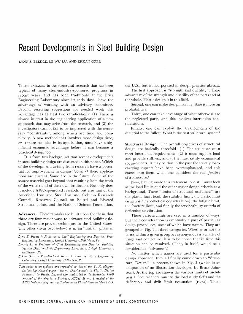
Fig. 9. Interior beam-to-column connection after testing
1. If we design the connection to transmit the moment through the flanges only and the web for shear only, will it be possible for these flanges to strain harden enough to develop the full plastic moment of the beam?
2. If we ignore the moment altogether when we design for shear, will we still be able to develop the full plastic shear capacity?
3. Will there be sufficient rotation for these condi
tions? 4. Will it be too flexible? 5. Can we predict it theoretically?
Figure 9 shows one of the connections after test. Notice how completely all of the material has "worked". For this case (and for this whole program) the connections were proportioned on the basis that everything was "critical". The shear was adjusted in such a way that the web would be fully yielded when Mv was reached. Grade 55 material was used. For the bolts, higher stresses were used than are now permitted, although they are both
8 0 0
P
6 0 0
4O0
2oO
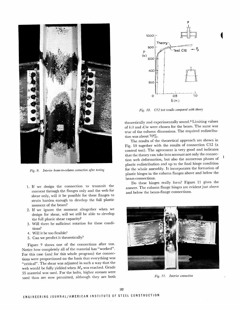
Fig. 10. CI 2 test results compared with theory
theoretically and experimentally sound.9 Limiting values of b/t and d/w were chosen for the beam. T h e same was true of the column dimensions. The required redistribution was about 70%.
The results of the theoretical approach are shown in Fig. 10 together with the results of connection CI2 (a control test). T h e agreement is very good and indicates that the theory can take into account not only the connection web deformation, but also the numerous phases of plastic redistribution and up to the final hinge condition for the whole assembly. I t incorporates the formation of plastic hinges in the column flanges above and below the beam connections.
Do these hinges really form? Figure 11 gives the answer. The column flange hinges are evident just above and below the beam-flange connections.
Fio 11. Interior connection
102
[NGINEERING J O U R N A L / A M E R I C A N I N S T I T U T E O F S T E E L C O N S T R U C T I O N

W 27 x 94 Beam W 14x176 Column A572 Gr. 55
(Fully-Welded)
Fig. 12. Load-deflection curves of three interior connections
Figure 12 shows the results of the tests with bolted webs. The reference load used in the figure is the plastic limit load, Pv. The other three loads are the working load Pw ( = Pp/1.7), the plastic load neglecting the contribution of the beam web, Ppr, and the plastic load modified to include the effect of shear, Pps. Connection C12 was fully welded. C2 used round holes, and C3 used slotted holes. The results indicate that all the connections carried maximum loads far exceeding the computed plastic loads Ppr and Pvs (and even Pv) and that the load-deflection relationships of the connections are very similar. T h e difference in behavior at loads above the working load was due to slip of the web plates occurring in the bolted connections. The high strength bolts eventually went into bearing against the sides of the holes, and the connections thus "regained" their stiffness. The effect of strain hardening is again the main reason for the connections to attain the high loads.
A detail view of connection G3, Fig. 13, shows the remarkable degree to which plastic action has taken place up to the point of final rupture. In flexure, in beam shear, in the connection plates, in the bolts, in the web panel, in the columns—throughout the entire assembly one observes complete yielding and redistribution under the most adverse possible conditions.10
The upcoming studies will cover web-connected beam-to-column connections and partial strength connections. These latter are most important because sometimes the depth of the girder is controlled by drift and not by the carrying capacity.
Mention is made here of an important guide for bolted and riveted joints.11 I t has been developed under the auspices of the Research Council for Riveted and Bolted Structural Joints. John Fisher and John Struik at Lehigh have been responsible for its preparation. As of
Fig. 13. Connection C3 after testing
this writing the manuscript is in the hands of John Wiley & Sons for eventual publication. The chapter headings are as follows:
1—General provisions 2—-Rivets 3—Bolts 4—-Symmetric butt splices 5—-Truss type connections 6—Shingle joints 7-—-Lap joints 8—Oversize and slotted holes 9—-Filler plates between surfaces
10—Alignment of holes 11—Surface coatings 12—Eccentrically loaded joints 13—-Combination joints 14—Gusset plates 15—Beam and girder splices 16—-Tension type connections 17—-Beam-to-column connections
Frames—Since the late 1950's an extensive research program has been carried out to develop plastic design methods for laterally braced and unbraced multi-story
F O U R T H Q U A R T E R / 1 9 7 3

frames. As par t of this program, a study was made to determine the factors that affect the ultimate strength of these frames. For unbraced frames, the secondary overturning moment (or the P-A moment) is found to be one of the most significant factors. The P-A moments caused by the gravity loads acting through the lateral deflection tend to reduce the overall strength and stiffness of the frame and lead to instability failure.12
There are two distinctive types of frame analysis: the first-order analysis in which the effect of secondary moment is ignored, and the second-order analysis in which this effect is included. T h e significant difference between the load-deflection curves obtained from the first- and second-order analyses is illustrated in Fig. 14 for a 3-story, 2-bay frame.13 T h e structure was par t of a test series which was designed to study the general behavior and load-carrying capacity of unbraced multistory frames. The substantial reduction in strength for the second-order case shows the importance of considering the P-A moment in the analysis and design of such frames. When the plastic method is used in the design, the effect of secondary moments can be included in a direct manner in the calculations. In the allowable-stress design, however, an indirect approach is generally used to account for this effect. This approach, which will be discussed briefly in the next section, was formulated before a thorough understanding of the frame instability problem was achieved. For this reason, there is a strong interest in knowing the real load-carrying capacity of frames designed by the allowable-stress method in order to assess the true factor of safety (or load factor).
Strength of Frames Designed by the Allowable-Stress
Method—The indirect approach mentioned above is based on the premise that the effect of frame instability can be taken care of by increasing the column sizes of the frame being designed. According to the AISC Specification, all columns in a planar frame are to be proportioned to satisfy the following two formulas:14
First-Oder Theory
fa , ^mfb
Fa [1 - (fa/F'e)]Fb < 1.0
fa 0.60FV
+ r̂ < 1.0
(3)
(4)
in which fa and fb are, respectively, the computed axial and bending stresses and
Fa = allowable axial stress if axial force alone existed Fb = allowable compressive bending stress if bending
moment alone existed = elastic Euler buckling stress divided by a factor
of safety. It is always computed for the in-plane case of buckling. In equation form, it is given by
F'
F' w2E
H
(kips)
Story Height=IOft. Bay Spacing =15 ft.
Fig. 14. Test results compared with first- and second-order theory
(Lb is the actual length in the plane of bending and rb the corresponding radius of gyration. K is the effective length factor in the plane of bending.)
Cm = 0.6 - OAM1/M2 > 0.4 for columns in braced frames. M1/M2 is the ratio of the smaller to larger moments applied at the ends of the member. I t is positive when the member is bent in reverse (double) curvature.
Cm = 0.85 for columns in unbraced frames.
If the columns in a frame are braced in the perpendicular direction, the in-plane effective slenderness ratio KLb/rb
is to be used in computing Fa. In the subsequent discussion, it will be assumed that this condition prevails for all the columns.
The effect of frame instability is recognized in two ways—the first is the use of the in-plane K factor in computing Fa and F'e, and the second is to assign a Cm value of 0.85 (instead of a much smaller value as given by the equation Cm = 0.6 - 0.4Afi/M2).
I.5I
I.3I
First - Order - ^ / Elastic \ /
/
/ / / ^—
// ^ - Second - Order // Elastic-Plastic
I
/ " irst Elast
-Ore i c - F
Firs t - O r der
ler ' last ic
77
—1 i — A
Seco
r ri
nd-C
r ri
)rder
H
1 A H
O.OIO
F.S. (KLb/rbY (5) Fig. 15. Load-deflection curves of a frame designed by allowable-stress
method without consideration of frame instability effect
104
E N G I N E E R I N G J O U R N A L / A M E R I C A N I N S T I T U T E OF STEEL C O N S T R U C T I O N

Frames Designed Without Considering Frame Instability Effects {Design A, see Fig. 15)—An extensive study of the load-carrying capacity of unbraced frames designed by the allowable-stress method has been carried out. A total of seven frames, varying from 10-story, 3-bay to 40-story, 2-bay, have been designed by the allowable-stress method and then analyzed plastically according to the first- and second-order theory. Figure 15 shows some of the results obtained for the 10-story, 3-bay frame. T h e frame was designed for the bending moment and axial force distributions determined from the first-order analysis and no consideration was given to the effect of frame instability, that is, K = 1.0 and Cm = 0.6 -0AMi/M2 were used in the design of the columns. All beams of the frame are made of A36 steel (yield stress = 36 ksi) and all columns A572, Grade 50 steel (yield stress = 50 ksi).15
T h e load factor (ultimate load/working load) of the frame from the first-order analysis is 1.51, and that from from the second-order analysis is 1.31. Thus the frame instability effect causes a reduction of the ultimate strength of 1 3 % . T h e load factor of all the frames studied falls in the range of 1.30 to 1.50.
The results to date indicate that frames designed by the allowable-stress method, but with no consideration being given to the overall instability effect, can achieve a load factor of 1.30 or more.16 This observation raises an important question: Is 1.30 adequate? The required load factor in plastic design for braced frames and for one-and two-story frames is set at 1.30 in the current AISC Specification for the case of combined gravity and wind loads. The same value is also specified in the specifications of such countries as Canada, Mexico, and Sweden (in this last case 1.34). Australia, India, South Africa, the United Kingdom, and the USSR use a load factor of 1.40. Reference 7 contains a summary of the plastic design load factors used in different countries.
Frames Designed to Include Frame Instability Effect {Designs B, C, and D, see Fig. 16)—Three different designs were made for the 10-story, 3-bay frame, all including the effect of overall instability:
Design B: Columns were designed for K — effective length factor determined for the sidesway mode of in-plane buckling (always greater than 1.0), and using Cm = 0.85.
Design C: Columns were designed for K = 1.0 and Cm = 0.85.
Both Designs B and C require increases in column sizes only; the beams are essentially unchanged.
Design D : A second-order design with beams and columns selected according to the bending moment and axial force distributions given by the second-order analysis. This design requires increases in both beam and column sizes and includes automatically the P-A moment at working load.
(a) (b)
Fig. 16. Comparison of load-deflection curves of a frame designed by allowable-stress method with and without consideration of frame
instability effect
Figure 16a shows the second-order load-deflection curves of Designs B and C together with that of Design A. The ultimate strength of the frame is increased 1 3 % for Design B and 1 0 % for Design C.
These results indicate that the use of the effective length factors determined for the sidesway mode of frame buckling does not significantly improve the strength of the frame.
A comparison of the ultimate strength of Designs B and D with that of Design A is shown in Fig. 16b. Design D, a more balanced design involving increases in both the beam and column sizes, achieves a load factor 1.43.
All three designs (B, C, and D) result in increases in the load-carrying capacity of 10 to 1 3 % , which is approximately equal to the reduction due to frame instability effect noted in Fig. 15. Among these designs, Design C is the simplest to perform.
In summary, if the results of these analyses are typical, a frame designed by the allowable-stress method according to the AISC Specification14, which indirectly includes the P-A effect by assuming the theoretical K-value and Cm of 0.85, will actually have a load factor in the vicinity of 1.5 (Design B).
I t also shows that frames designed before 1960, in which the effective length and P-A effects are ignored have a load factor of at least 1.3. The resulting body of experience would lead one to assume that a load factor of 1.3 is probably satisfactory for the plastic design of unbraced frames.*
Thus (within the limitations of calculations made) these results point to significant potential improvements. A separate paper is in preparation on the subject.16
There are some important provisos: T h e frames in the analyses were two-dimensional planar frames of regular geometry, the Z/r-values were in the practical range, there were no setbacks, and the moment diagram was not an arbitary one (such as would be obtained by the cantilever or portal method).
* The present specifications permit plastic design of braced multistory frames with a load factor of 1.70 for gravity load and 1.30 for combined load. Application to unbraced frames will be ready shortly, and this experimental evidence for a factor of 1.30 is reassuring.11
105
F O U R T H Q U A R T E R / 1 9 7 3

, DESIGN
LOADING
DEAD LOAD
LIVE LOAD Long Term Short Term Extraordinary
COMBINATIONS
RESISTANCE
PLASTIC LIMIT STABILITY
LIMIT ELASTIC LIMIT FATIGUE FRACTURE DEFLECTION (VIBRATION)
Fig. 17. Loading function and resistance function as equated in design
Naturally, in plastic design one would have to take into account the frame instability effect in a direct way— for which provisions are available.12
DESIGN BASED ON PROBABILITY
The second technique for advance given earlier was to make design more like life—to base it on probabilities.
Load-factor/limit-states design is a method of proportioning structures for multiples of service load. The design ultimate loads are obtained by applying factors to the service loads and these are related to the resistance of the structure. This resistance (or "response function") is itself subject to factors. So the method of "Load-factor and limit-states design"* involves a consideration of the "Loading Funct ion" (the dead load, the several kinds of live loads, the various combinations of these loads, and the load factors that are going to be applied), and of the "Resistance Funct ion" (according to the applicable limit of usefulness). These functions are shown in Fig. 17, which also points to the design process as equating the loading function with the resistance function (through the appropriate analytical techniques). I t involves a decision on the load factors and a conscious attention to the appropriate limit of usefulness.18
Figure 18 affords a partial comparison with allowable-stress design. As shown at the left, in allowable-stress design one uses the service dead load and live load, and the total must be less than the allowable load Pa. In load-factor design, illustrated here in simplistic terms by plastic design, we take a factor times the dead load and a factor times the live load and add them together to obtain Pu. T h e plastic limit load of the structure, Pp, is selected so that it is greater than the design ultimate load Pu. (To the right is shown one effect of the use of multiple load factors. With this technique, one separates out the load factors for live load and dead load on the assumption that different factors can be used.19 In this case, one would expect that the factor for the dead load
* The other terms shown in the lower portion of Fig. 1 would be just as appropriate here.
Fig. 18. Allowable-stress design compared with load-factor and limit-states design
will be lower and the factor for the live load will be greater. But one can still find that the total loading function will permit selection of a smaller section. T h e second design would be lighter than the first.)
The matter does not stop here. Separating the loading function and the response function opens the way to consider probability. But at the same time this is the biggest uncertainty when it comes to future design application. Wha t are the sources of possible uncertainty that can or should be subjected to such consideration? T h e following is a list, expanding on the one contained in ASCE Manua l 41 . 7
1. Approximations in analysis 2. Approximations in design 3. Stress concentration and residuals 4. Variation in properties 5. Variation in dimensions 6. Workmanship 7. Location 8. Variation in load type 9. Combination of loads
10. Intended use
They enter into what we presently call the factor of safety in allowable-stress design, or into the load factor in plastic design. In load-factor design some would enter in the loading function and some in the response function. All of them are sources of possible uncertainty.
This uncertainty of loading and of response is reflected in Fig. 19, which is perhaps a more "precise" way oi representing the right side of Fig. 18. Again it is based or a hypothetical load vs. deflection curve of a frame. The horizontal line at the plastic limit load is not a fixec value, but is subject to variation. The variation would b( due to such things as the yield point or the dimensions o the shape. The statistical variation in the resistance i; suggested by the function fR. Similarly for load—the loac is uncertain, its actual value can vary considerably, anc that is why we have a factor in the first place. A hypo thetical statistical variation in the load is indicated ii
106
E N G I N E E R I N G J 0 U R N A L / A M E R I C A N I N S T I T U T E OF S T E E L C O N S T R U C T I O N
p _, /
1 /
FD
_k_\
/£
vf* JL^
vA
fr FJL<FrR
Fig. 79. Variation of loading and response functions
Fig. 19 by the function fL. (It reflects a larger spread than that for the resistance function.)
Thus in the actual design, according to the load-factor and limit-states design concept, the criterion is not that the upper end of the bar F D in Fig. 19 be less than the horizontal line at Pp, but that the maximum probable value of the load F\L must be less than the minimum carrying capacity FrR. In equation form this means tha t :
FXL < Fr<R (6)
Is load- and response-factor design a suitable alternative for allowable-stress design? In arriving at a decision, these are the things we have to think about: the concept of the multiple load factors; the rational choice of these factors; the possible combinations to be specified; and the potential economy vs. the complexity.
T h e American Iron and Steel Institute is sponsoring a major program at Washington University, St. Louis, under the direction of T . V. Galambos, that is examining many of these factors.20 One needs answers to such questions as these: Wha t are the statistical variations? Wha t are the variations of load? Wha t are the economies—will time and material be saved?
INTERACTION CONSIDERATIONS
The third topic, interaction considerations, involves taking advantage of the otherwise strength-neglected parts of the structure. The discussion falls into these four categories: (1) Floor systems and shear connectors, (2) developing composite action at the columns, (3) integrated structural design, and (4) mixed systems.
Floor Systems and Shear Connectors—Work on floor systems and shear connectors has its primary focus on the behavior of the different available types of manufactured floor systems. When one takes into account composite action in the positive moment region, not only is there a strength advantage, but the increase in stiffness is often a significant design improvement. In Ref. 21 recent developments in this area are described.
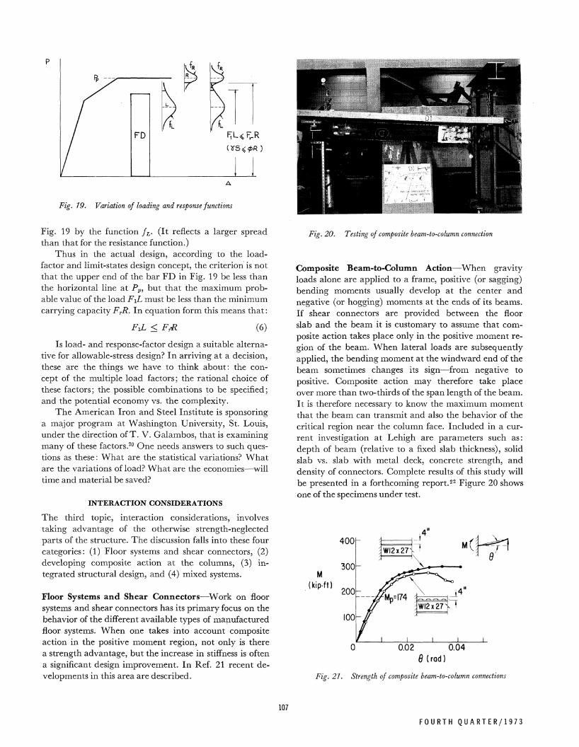
Fig. 20. Testing of composite beam-to-column connection
Composite Beam-to-Column Action—When gravity loads alone are applied to a frame, positive (or sagging) bending moments usually develop at the center and negative (or hogging) moments at the ends of its beams. If shear connectors are provided between the floor slab and the beam it is customary to assume that composite action takes place only in the positive moment region of the beam. When lateral loads are subsequently applied, the bending moment at the windward end of the beam sometimes changes its sign—from negative to positive. Composite action may therefore take place over more than two-thirds of the span length of the beam. It is therefore necessary to know the maximum moment that the beam can transmit and also the behavior of the critical region near the column face. Included in a current investigation at Lehigh are parameters such as: depth of beam (relative to a fixed slab thickness), solid slab vs. slab with metal deck, concrete strength, and density of connectors. Complete results of this study will be presented in a forthcoming report.22 Figure 20 shows one of the specimens under test.
0.02 0.04 0(rad)
Fig. 27. Strength of composite beam-to-column connections
107
F O U R T H Q U A R T E R / 1 9 7 3

Fig. 22. Test building with composite floor and partition
Figure 21 shows the results of two tests—one with a solid slab and the other with its slab cast on a metal deck. T h e inset in the sketch shows the loading system dia-grammatically. T h e behavior and the maximum resisting moment of the two beams are very similar, and they both failed after the concrete near the column face was extensively crushed. The plastic moment of the W12X27 shape is 174 kip-ft and the maximum moment carried by the specimen having a solid slab is more than 300 kip-ft, an increase of about 80%. In addition to increasing the strength of the beam, composite action also increases its stiffness, thus reducing the overall frame drift under wind. The effect of a small gap between the concrete slab and the column face was also examined in the study; it is similar to the effect of slip in a bolted joint : After coming into bearing, the stiffness becomes that of a member without the gap.
Composite Floors
Bare Frame
— o Experimental Theoretical
Integrated Structural Design—The third topic under interaction considerations embraces not only the two prior topics, but also the strength and stiffening effects of floors and partitions when acting in conjunction with the bare frame.
In the experimental portion of the study at Lehigh, a half-scale test building, consisting of a steel framework, a composite floor system, and light-gage corrugated partitions, was constructed. A photograph of this "building" is shown in Fig. 22. The structure was first tested without the floor system and the partitions. The concrete floor slabs were then connected to the steel beams by mechanical fasteners and the test repeated. Finally, the corrugated partitions were added to the frame-floor system to study their stiffening effect.
Some sample results from the testing are shown in Fig. 23. These results compare very favorably with theoretical predictions developed in Ref. 23. I t may be concluded for the test building that the major interaction is between the frame and the partitions, with the floor system contributing about 5 % to the total stiffness.
Mixed Systems—The fourth topic under interaction considerations is "mixed systems". The Japanese have made notable use of this scheme which combines the best features of both steel and concrete, under the designation "steel-reinforced concrete frames". I t is like building a steel frame and then putting reinforced concrete around it. Figure 24 is a typical example.
100 200 3 0 0 400 500 A(xl0"3 in.)
Fig. 23. Increase in building stiffness due to floor and partition Fig. 24. Mixed system (Wakabayashi)
108
E N G I N E E R I N G J 0 U R N A L / A M E R I C A N I N S T I T U T E OF STEEL C O N S T R U C T I O N
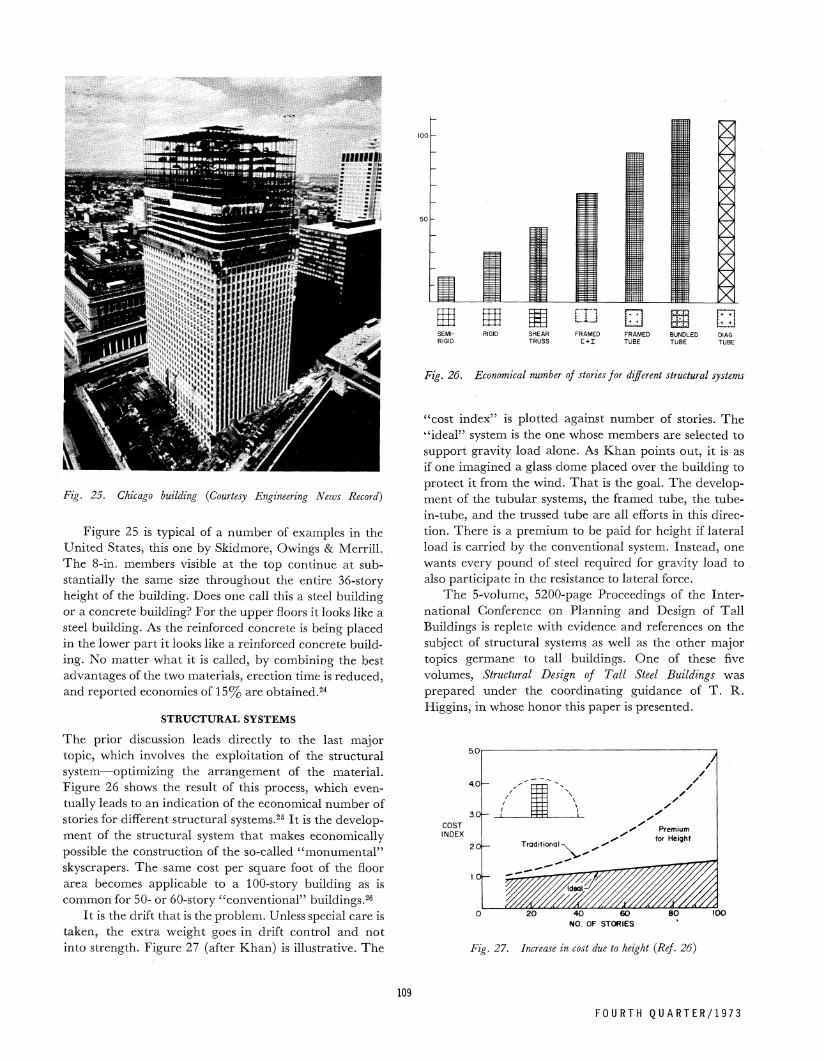
Fig. 25. Chicago building {Courtesy Engineering News Record)
Figure 25 is typical of a number of examples in the United States, this one by Skidmore, Owings & Merrill. T h e 8-in. members visible at the top continue at substantially the same size throughout the entire 36-story height of the building. Does one call this a steel building or a concrete building? For the upper floors it looks like a steel building. As the reinforced concrete is being placed in the lower par t it looks like a reinforced concrete building. No matter what it is called, by combining the best advantages of the two materials, erection time is reduced, and reported economies of 1 5 % are obtained.24
STRUCTURAL SYSTEMS
The prior discussion leads directly to the last major topic, which involves the exploitation of the structural system—optimizing the arrangement of the material. Figure 26 shows the result of this process, which eventually leads to an indication of the economical number of stories for different structural systems.25 I t is the development of the structural system that makes economically possible the construction of the so-called "monumenta l " skyscrapers. The same cost per square foot of the floor area becomes applicable to a 100-story building as is common for 50- or 60-story "conventional" buildings.26
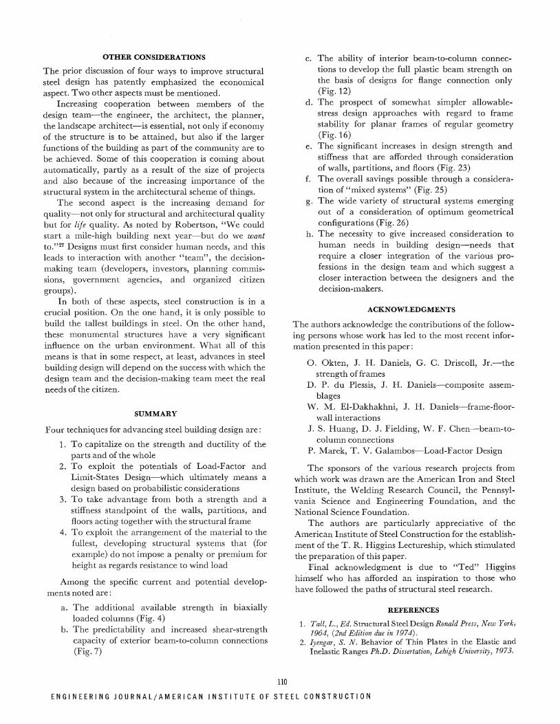
I t is the drift that is the problem. Unless special care is taken, the extra weight goes in drift control and not into strength. Figure 27 (after Khan) is illustrative. T h e
SEMI- RIGID SHEAR FRAMED FRAMED BUNDLED DIAG. RIGID TRUSS C + I TUBE TUBE TUBE
Fig. 26. Economical number of stories for different structural systems
"cost index" is plotted against number of stories. T h e " ideal" system is the one whose members are selected to support gravity load alone. As Khan points out, it is as if one imagined a glass dome placed over the building to protect it from the wind. Tha t is the goal. The development of the tubular systems, the framed tube, the tube-in-tube, and the trussed tube are all efforts in this direction. There is a premium to be paid for height if lateral load is carried by the conventional system. Instead, one wants every pound of steel required for gravity load to also participate in the resistance to lateral force.
T h e 5-volume, 5200-page Proceedings of the International Conference on Planning and Design of Tall Buildings is replete with evidence and references on the subject of structural systems as well as the other major topics germane to tall buildings. One of these five volumes, Structural Design of Tall Steel Buildings was prepared under the coordinating guidance of T . R. Higgins, in whose honor this paper is presented.
0 20 40 60 80 100 NO. OF STORIES
Fig. 27. Increase in cost due to height (Ref. 26)
109
F O U R T H Q U A R T E R / 1 9 7 3
OTHER CONSIDERATIONS
The prior discussion of four ways to improve structural steel design has patently emphasized the economical aspect. Two other aspects must be mentioned.
Increasing cooperation between members of the design team—the engineer, the architect, the planner, the landscape architect—is essential, not only if economy of the structure is to be attained, but also if the larger functions of the building as par t of the community are to be achieved. Some of this cooperation is coming about automatically, partly as a result of the size of projects and also because of the increasing importance of the structural system in the architectural scheme of things.
The second aspect is the increasing demand for quality—not only for structural and architectural quality but for life quality. As noted by Robertson, " W e could start a mile-high building next year—but do we want to."2 7 Designs must first consider human needs, and this leads to interaction with another " team" , the decisionmaking team (developers, investors, planning commissions, government agencies, and organized citizen groups).
In both of these aspects, steel construction is in a crucial position. O n the one hand, it is only possible to build the tallest buildings in steel. On the other hand, these monumental structures have a very significant influence on the urban environment. What all of this means is that in some respect, at least, advances in steel building design will depend on the success with which the design team and the decision-making team meet the real needs of the citizen.
SUMMARY
Four techniques for advancing steel building design are:
1. To capitalize on the strength and ductility of the parts and of the whole
2. To exploit the potentials of Load-Factor and Limit-States Design—which ultimately means a design based on probabilistic considerations
3. To take advantage from both a strength and a stiffness standpoint of the walls, partitions, and floors acting together with the structural frame
4. To exploit the arrangement of the material to the fullest, developing structural systems that (for example) do not impose a penalty or premium for height as regards resistance to wind load
Among the specific current and potential developments noted are:
a. The additional available strength in biaxially loaded columns (Fig. 4)
b . The predictability and increased shear-strength capacity of exterior beam-to-column connections (Fig. 7)
c. T h e ability of interior beam-to-column connections to develop the full plastic beam strength on the basis of designs for flange connection only (Fig. 12)
d. The prospect of somewhat simpler allowable-stress design approaches with regard to frame stability for planar frames of regular geometry (Fig. 16)
e. The significant increases in design strength and stiffness that are afforded through consideration of walls, partitions, and floors (Fig. 23)
f. The overall savings possible through a consideration of "mixed systems" (Fig. 25)
g. The wide variety of structural systems emerging out of a consideration of opt imum geometrical configurations (Fig. 26)
h. The necessity to give increased consideration to human needs in building design—needs tha t require a closer integration of the various professions in the design team and which suggest a closer interaction between the designers and the decision-makers.
ACKNOWLEDGMENTS
The authors acknowledge the contributions of the following persons whose work has led to the most recent information presented in this paper:
O. Okten, J. H. Daniels, G. C. Driscoll, Jr .—the strength of frames
D. P. du Plessis, J. H. Daniels—composite assemblages
W. M. El-Dakhakhni, J. H. Daniels—frame-floor-wall interactions
J. S. Huang, D. J. Fielding, W. F. Chen—beam-to-column connections
P. Marek, T . V. Galambos—Load-Factor Design
The sponsors of the various research projects from which work was drawn are the American Iron and Steel Institute, the Welding Research Council, the Pennsylvania Science and Engineering Foundation, and the National Science Foundation.
The authors are particularly appreciative of the American Institute of Steel Construction for the establishment of the T . R. Higgins Lectureship, which stimulated the preparation of this paper.
Final acknowledgment is due to " T e d " Higgins himself who has afforded an inspiration to those who have followed the paths of structural steel research.
REFERENCES
1. Tall, L., Ed. Structural Steel Design Ronald Press, New York, 7964, (2nd Edition due in 7974).
2. Iyengar, S. N. Behavior of Thin Plates in the Elastic and Inelastic Ranges Ph.D. Dissertation, Lehigh University, 7973.
110
E N G I N E E R I N G J 0 U R N A L / A M E R I C A N I N S T I T U T E OF STEEL C O N S T R U C T I O N

3. Negussie, T., and Chen, W. F. Design Criteria for Steel H-Columns under Biaxial Loading Fritz Engineering Laboratory Report 389.2, Lehigh University, January 7973.
4. Johnston, B. G., Ed. Guide to Design Criteria for Meta l Compression Members 2nd Edition John Wiley & Sons, Inc., New York, 7966 (3rd Edition in preparation).
5. Fielding, D. J. and Huang, J. S. Shear in Steel Beam-to-Column Connections Welding Journal, Vol. 50, No. 7, July 7977, p. 373s.
6. Fielding, D. J., and Chen, W. F. Steel Frame Analysis and Connection Shear Deformation Journal of the Structural Division, ASCE, Vol. 99, STI, January 7973, p. 7.
7. ASCE-WRC Plastic Design in Steel—A Guide and Commentary 2nd Edition, ASCE Manual 47, 7977.
8. Huang, J. S., W. F. Chen and L. S. Beedle Behavior and Design of Steel Beam-to-Column Moment Connections Fritz Engineering Laboratory Report 333.20, Lehigh University, 7973.
9. Fisher, J. W. and Beedle, L. S. Criteria for Designing Bearing-Type Bolted Joints Journal of the Structural Division, ASCE, Vol. 97, ST5, October 7965, p. 729.
10. Huang, J. S., and Chen, W. F. Steel Beam-to-Column M o ment Connections presented at ASCE National Structural Engineering Meeting held at San Francisco, April 7973, ASCE Preprint No. 7920.
11. Struik, J. H., and Fisher, J. W. Design Guide to Mechanically Fastened Joints Fritz Engineering Laboratory Reports 357.7-77, Lehigh University, 7972 (to be published).
12. Driscoll, G. C, Jr. et al. Plastic Design of Multi-Story Frames Lecture Notes and Design Aids, Fritz Engineering Laboratory Reports 273.20 and 273.24, Lehigh University, 7965.
13. Galambos, T. V., G. C. Driscoll, Jr., and L. W. Lu Research on Plastic Design of Multi-Story Frames at Lehigh University 8th Congress of IABSE, Final Report, September 7968, p. 577.
14. American Institute of Steel Construction Specification for the Design, Fabrication and Erection of Structural Steel for Buildings AISC, New York, February 7969.
15. Lu, L.W., and Beedle, L. S. Recent Research on the Strength, Stiffness and Ductility of Steel Buildings Fritz Engineering Laboratory Report 369.79, Lehigh University, July 7973 (to be
published in Proceedings, Australian Conference on the Planning and Design of Tall Buildings).
16. Okten, 0., S. Morino, J. H. Daniels, and L. W. Lu Studies of Effective Column Length and Frame Stability Fritz Engineering Laboratory Report 375.2 Lehigh University, 7973.
17. Driscoll, G. C, Jr. Plastic Design of Unbraced Mult i -Story Steel Frames American Iron and Steel Institute (in preparation).
18. Beedle, L. S., L. W. Lu, and L. C. Lim Recent Developments in Plastic Design Practice Journal of the Structural Division, ASCE, Vol. 95, ST9, September 7969, p. 7977.
19. Marek, P. J. Review of Czechoslovak and French Specifications Fritz Engineering Laboratory Report 377.2A, Lehigh University, 7973.
20. Galambos, T. V. Load Factor Design for Steel Buildings Engineering Journal, AISC, Vol. 9, No. 3, July 7972, p. 708.
21. Grant, J. A., Jr., J. W. Fisher, and R. G. Slutter, High-Strength Steel Composite Beams with Formed Meta l Deck and Low Partial Shear Connection presented at the Second Specialty Conference on Cold-Formed Steel Structures at the University of Missouri—Rolla, St. Louis, Missouri, October 7973.
22. du Plessis, D. P., and Daniels, J. H. Strength of Composite Beam-to-Column Connections Fritz Engineering Laboratory Report 374.3 Lehigh University, 7973.
23. El-Dakhakhni, W. M., and Daniels, J. H. Frame-Floor-Wall System Interaction in Buildings Fritz Laboratory Report 376.2, Lehigh University, 7973.
24. Fox, A. J., Jr., Ed. Building Design Reduces Steel with Concrete-Tube Wind Bracing Engineering News Record, Vol. 786, No. 22, June 3, 7977, p. 78.
25. Iyengar, S. H. Preliminary Design and Optimization of Steel Building Systems Proceedings of the International Conference on the Planning and Design of Tall Buildings, Lehigh University, 7972, Vol. 7 7, p. 785.
26. Khan, F. R. T h e Future of High-Rise Structures Progressive Architecture, October, 7972.
27. Fox, A. J., Jr., Ed. High-Rise Experts Score Present Planning, Stress Impact , Safety Engineering News Record, Vol. 789, No. 9, August 37, 7972, p. 72.
F O U R T H Q U A R T E R / 1 9 7 3