Recent Developments and Roadmap Part 1: LS - · PDF file1 Recent Developments and Roadmap Part...
43
1 Recent Developments and Roadmap Part 1: LS-PrePost 12 th International LS-DYNA User’s Conference June 5, 2012
Transcript of Recent Developments and Roadmap Part 1: LS - · PDF file1 Recent Developments and Roadmap Part...

1
Recent Developments and Roadmap Part 1: LS-PrePost
12th International LS-DYNA User’s Conference June 5, 2012

• Introduction
• Recent developments
• Conclusions
Outline
LS-PrePost Philip Ho
Dummies Christoph Maurath
Incompressible CFD Dr. Facundo Del Pin
Electromagnetics Dr. Pierre L’Eplattenier
ALE, DEM, SPH, Particle Dr. Jason Wang
Mr. Philip Ho
Dr. Christoph Maurath
Dr. Jason Wang

LS-PrePost Philip Ho

Outline of Talk
• Current status of LS-PrePost and the different releases
• New GUI of LS-Prepost 3.x/4.0
• New graphics rendering in 4.0
• Other New Features in LS-PrePost 3.2/4.0
• Current and future developments
• Summary and Conclusion
5
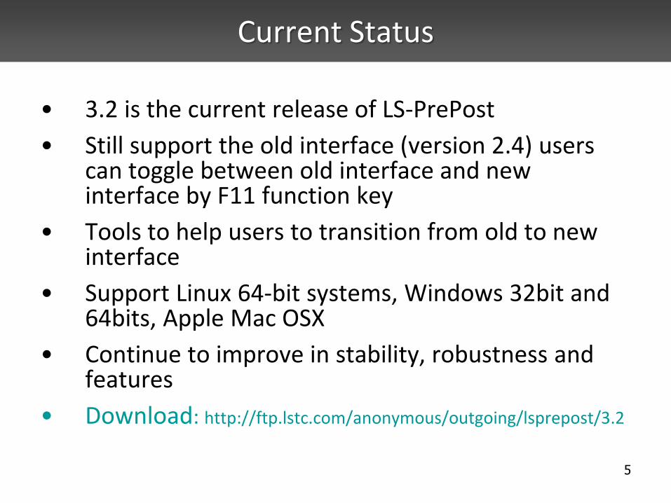
Current Status
• 3.2 is the current release of LS-PrePost
• Still support the old interface (version 2.4) users can toggle between old interface and new interface by F11 function key
• Tools to help users to transition from old to new interface
• Support Linux 64-bit systems, Windows 32bit and 64bits, Apple Mac OSX
• Continue to improve in stability, robustness and features
• Download: http://ftp.lstc.com/anonymous/outgoing/lsprepost/3.2
6
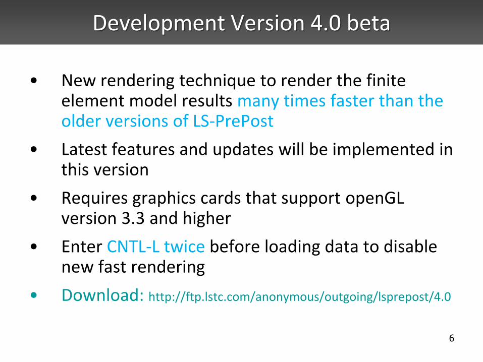
Development Version 4.0 beta
• New rendering technique to render the finite element model results many times faster than the older versions of LS-PrePost
• Latest features and updates will be implemented in this version
• Requires graphics cards that support openGL version 3.3 and higher
• Enter CNTL-L twice before loading data to disable new fast rendering
• Download: http://ftp.lstc.com/anonymous/outgoing/lsprepost/4.0

Old Interface

New Interface

9
LS-PrePost 3.2/4.0 GUI
Icons WithText
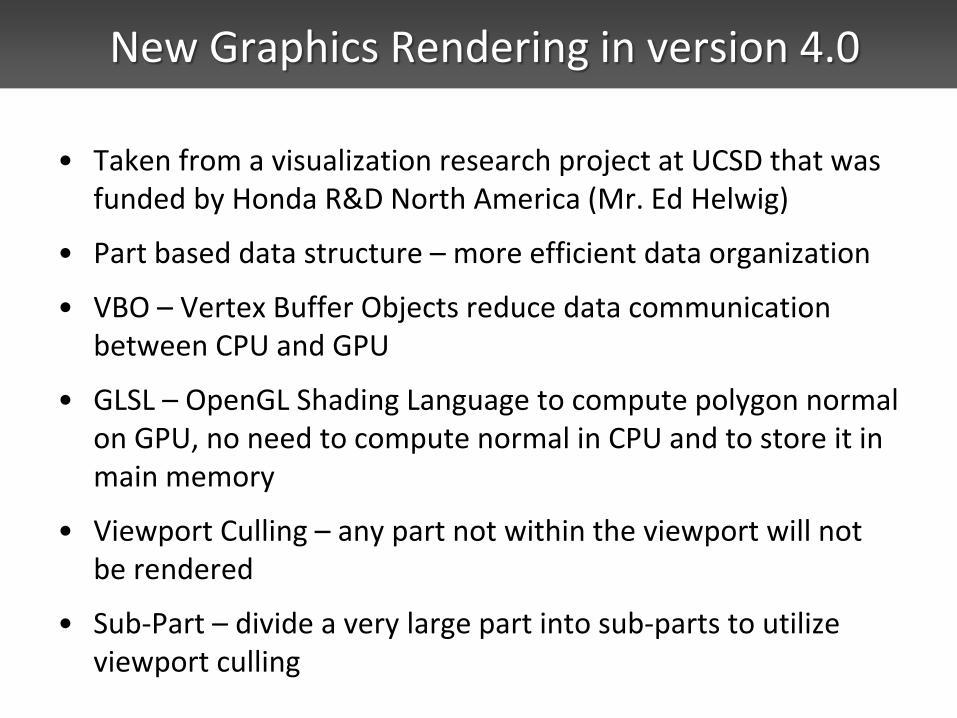
New Graphics Rendering in version 4.0
• Taken from a visualization research project at UCSD that was funded by Honda R&D North America (Mr. Ed Helwig)
• Part based data structure – more efficient data organization
• VBO – Vertex Buffer Objects reduce data communication between CPU and GPU
• GLSL – OpenGL Shading Language to compute polygon normal on GPU, no need to compute normal in CPU and to store it in main memory
• Viewport Culling – any part not within the viewport will not be rendered
• Sub-Part – divide a very large part into sub-parts to utilize viewport culling

New Rendering Performance
• 5.65million elements (4.29m Shells, 1.36m solids, some beams, 1680 parts), 59 states
• On HP Z800 8-core, with Nvidia Quadro 6000, timing in frames/sec
Old New
Static Rendering 2.1 30.4
Animation 1st
loop 1.3 14.2
Avg. Animation 2.1 16.5

New Rendering Performance
• 10.65million elements (8.44m Shells, 2.21m solids, 5223 beams, 816 parts), 49 states
• Spot weld beam was drawn as circle
• On HP Z800 8-core, with Nvidia Quadro 6000, timing in frames/sec
Old New Speed up
Static Rendering 1.2 22.1 18
Animation 1st loop 0.4 10.2 --
Avg Animation loop 1.25
10.5 8.4

User group and Online Documentation
• User Group – more than 2200 members as of May, 2012
– http://groups.google.com/group/ls-prepost
• Documentation and tutorials can be accessed from the pull down HELP menu

Other new features and improvements in
LS-PrePost3.2/4.0

Batch mode Operation – (-nographics)
• Batch mode operation with full graphics capability using LS-Prepost
• Run lsprepost 3.2 with command file and use -nographics
• Works very well on PC/Windows platforms
• Has limitations on Linux platforms: – Machine to run lsprepost with –nographics must have
OpenGL and X capability – Local machine that logs into the remote machine must
also have OpenGL and X capability – If the above conditions not met, use the Linux virtual
frame buffer (Xvfb) for batch mode: • Xvfb :2 -screen 0 1074x800x24
LS-PREPOST Features for LS-980
• Support for Multi-Physics keywords: *CESE, *ICFD and *EM
• Multi-Solver keyword files can be displayed and edited
• Models can be a mixture of Multi-Solver and Mechanical meshes
• ICFD modeling can be 2D or 3D with mesh adaption (re-meshing)
• Support for ICFD LevelSet functions

CESE with stochastic particles
Fringe by size with velocity vectors
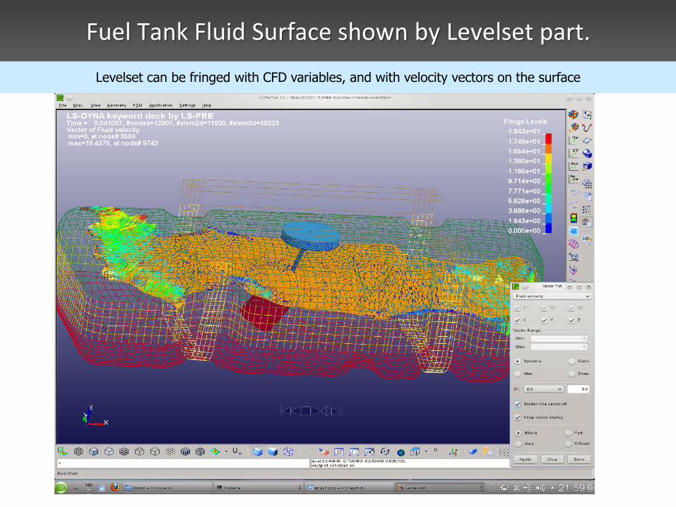
Fuel Tank Fluid Surface shown by Levelset part.
Levelset can be fringed with CFD variables, and with velocity vectors on the surface

New XYPLOT layout
• New XY plot interface allows xy plots to be drawn to main graphics windows, or to a separate page with multiple plots per page


Fringing by Script
• In the fringe expression interface, use script (a programming code) instead of expression
• Assign components to variables
• User writes the script (code) to perform whatever data manipulation to get final result
Toggle to use script Browse to choose script file
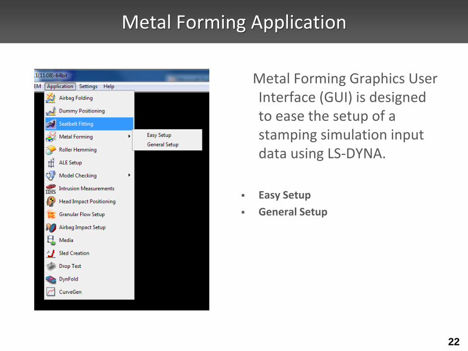
Metal Forming Application
Metal Forming Graphics User Interface (GUI) is designed to ease the setup of a stamping simulation input data using LS-DYNA.
Easy Setup
General Setup
22

Metal Forming → Toolbar
23
Metal Forming Pre-Processing
Metal Forming Post-Processing

Metal Forming → eZsetup
Standard draw type
Step-by-step tool definition
Easy draw bead modeling
Automatic tooling position
Multiple processes
User control options
24

DynFold Application
• Dynfold is designed to prepare input files for simulation based airbag folding process. Typical physical airbag folding process is done in 4 to 5 steps (runs of LS-DYNA).
• Dynfold user interface is designed to setup one step at a time. Often the deformed shape at the end of one folding step is used as a starting mesh for the next step.
• The airbag model is expected to have nodes, elements, part, section and material defined before using this interface.
• The physical folding process is generally of the following form: a. hold the bag in position while being folded b. clamp a portion of the bag to a folding tool c. Apply motion to the tool in translational direction or rotational direction or combination of both.
• At present 4 folding tools are supported: Loadmesh, SPC, BPMF(BOX), Stitching and Tuck

DynFold Setup Process
• Define Parameters: Define Project Step Name, Termination time, airbag tool Material Parameters.
• Load Airbag: Load finite element mesh, Position airbag by translate, rotation, etc.; show airbag, or turn off show.
• Define Airbag Folding Tools, currently there are four kinds of tools
• Load meshing:
– Load tool meshing file; Define tool attaching to bag. – Define Load Meshing Tools Motion. – Preview tool motion ( Home position and Final position)
• Spc_Birth_Death, BPMF(Box), Stitch

• Spc_Birth_Death, BPMF(Box), Stitch • Define boundary spc node set.
• Define Constrained
• Define Birth and Death time.
• BPMF(Box) • Define Original and Final position of the Box.
• Define contact between box and airbag parameters .
• preview of Original/Target position of the box in graphics view .
• Stitch • Define Stitch parts and parameters.
• Define Get stitch start position and direction.
• Define stitch Birth and Death time

Define Part Motion with motion properties

*Airbag_shell_reference_geometry
• *Airbag_shell_reference_geometry is the required data for airbag deployment in LS-DYNA
• LS-Prepost creates this data by asking user to pick the parts that make up the airbag in 3D final configuration and unrolls them into 2D flat panels.
• Element IDs are preserved with new nodal coordinates

*Airbag_shell_reference_geometry
Pick this part to be unrolled
*Airbag_shell_ref_geometry

Part Replace
• Model->PartD->Replace
• To replace a part with another part
• The 2 parts do not need to be the same in no. of elements/nodes.
• Connection between others part will be done automatically when it is possible

Old part New part
Beams are connected properly automatically
Part Replacement
Other Miscellaneous Improvements
• Many bugs have been fixed in geometry engine
• Improved mid-surface generation from solid model
• More robust trimming and solid cutting
• Improved automatic solid meshing
• More robust LS-DYNA model checking with auto fixing
• Particle, temperature post-processing data support in FEMZIP format
• Solid element and seatbelt element splitting
• Element edit with check, locate and repair

User written script
• C-like programming scripting language to execute LS-PrePost commands
• Allows “if then else”, for, and while loop operations
• Uses LS-PrePost DataCenter to extract model data: like no. of parts, part ID, no. of elements, no. of nodes, etc.
• Extracted data can be used as variables to perform operations
• Most suitable to perform the same operations over different part of the model

User written script
/*LS-SCRIPT:PartId repeat cmd*/
DataCenter dc;
Int partnum, *ids;
define:
void main(void)
{
Int i = 0;
char buf[256];
Int modelId;
modelId = GetCurrentModelID();
DataImportFrom(&dc,modelId);
partnum = DataGetValidPartIdList(&dc,&ids);
for(i = 0; i < partnum ; i = i+1)
{
sprintf(buf,"m %d",ids[i]);
ExecuteCommand(buf);
ExecuteCommand("ac");
sprintf(buf,"print png part_%d.png LANDSCAPE nocompress gamma 1.000 opaque enlisted
\"OGL1x1\"", ids[i]);
ExecuteCommand(buf);
}
free(ids);
} main();
Sample script to extract no. of parts and all part IDs, then draw each individual part and print it to a file with the part id as file name

Suppress Boundary line for surface meshing
Common boundary lines between two surfaces can be suppressed to form a joint surface, this will allow the mesh to cross boundary lines to give better mesh

Solid Meshing with Hex Element
• Solid meshing by blocks - using cut and dice method and then sweeping
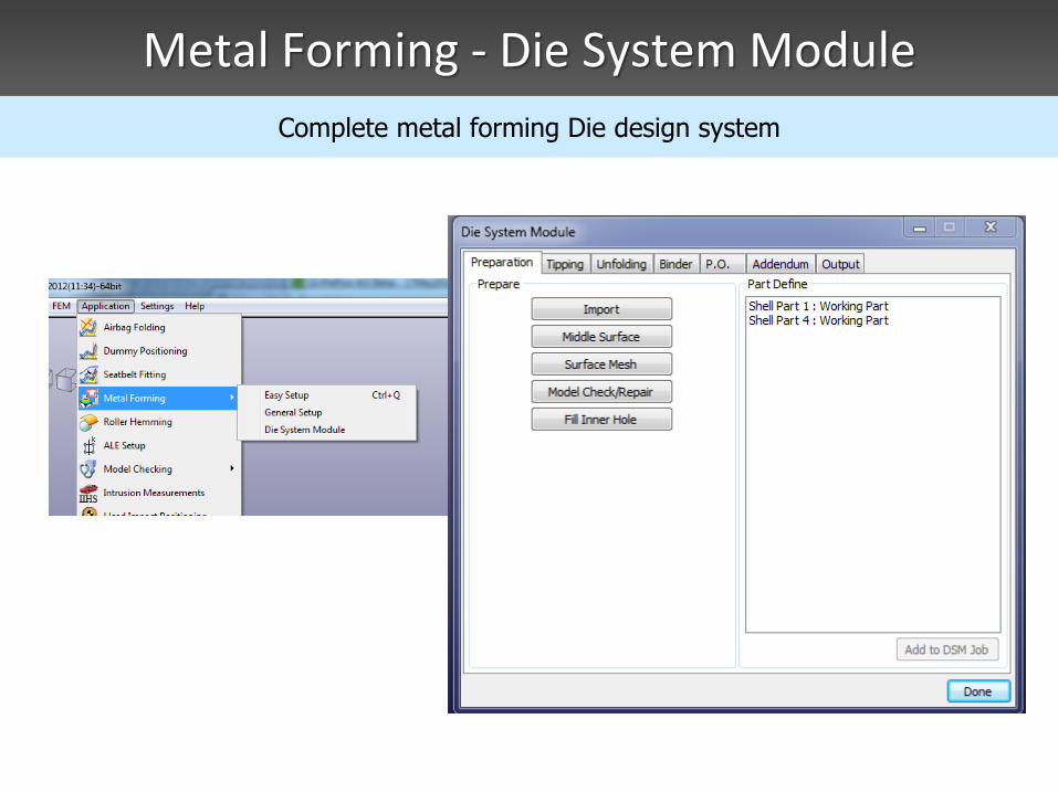
Metal Forming - Die System Module
Complete metal forming Die design system

Metal Forming - Die System Module
• Provides a user friendly interface to design the complete tooling system – Starting from CAD geometry
– Tipping: make sure that the part can be made without undercut
• Many options are available to allow user to check and position the part with a desired orientation
– Binder design is fully parametric
• User can easily manipulate the binder surface
– Addendum design – obtain a smooth surface that is tangent to both the tool part and the binder
• To make sure that the part can be deformed correctly
• Parametric patch method will be employed
– Initial blank size estimation – one step solver

THUMS Positioning Setup
• THUMS – Total Human Model for Safety
• THUMS positioning Setup – Setup LS-DYNA keyword data to position the dummy by simulation
– H-point and Joint method – define amount and direction of rotation at joint
– Tools method – introduce tools to pull or move the limbs to a desired location

Summary
• New GUI provides better look and feel, also yields maximum windows space for graphics, at the same time old interface is still available to user
• Capabilities in the geometry engine allows CAD data to be modified and repaired before meshing and therefore eliminate tedious mesh modification
• New rendering in Version 4.0 employs the latest rendering techniques in OpenGL, speeds up the rendering by many times, viewing and animation of a very large model now is possible
• LS-DYNA model data check is a very important tool to ensure the validity of the data before running LS-DYNA
• Scripting language will be further developed to provide much more powerful capability

LS-PrePost Recap
LSTC is committed to continue to develop and enhance LS-Prepost by improving its stability, robustness and user
friendliness
New features have been added continuously to keep up with the development of LS-DYNA both in the post-
processing and pre-processing
New Applications have been implemented to let user do special LSDYNA job setup easily and quickly
Users’ feedback and suggestions are always welcome

Thank You !