Recent development of MRAM and related phenomena
7
Trans. Magn. Soc. Japan, 4, 67-73 (2004) Recent development of MRAM and related phenomena T. Miyazaki Department of Applied Physics, Graduate School of Engineering, Tohoku University, Aramaki aza aoba05.Sendai 980-8579 The history of MRAM development, including the toggling method and future perspectives were reviewed. Also, the giant TMR effect reported quite recently for MgO barrier junction and Heusler electrode junction was introduced In addition, spin dynamics, which are closely related with high speed and large capacity MRAM technologies, was shown. Especially, the enhancement of Gilbert damping constant was introduced. Key words MRAM, TMR, MgO barrier. Heusler electrode, Toggling, operating window, spin dynamics, spin-transfer, Gilbert damping constant 1. Introduction Semiconductors and magnetic materials play an important role in the electronic devices that support present-day communication industries. Data processing is carried out by carrier charges in semiconductor devices. In contrast, hard disk drives, which are representative of electron devices using magnetic materials perform data processing using spin in the magnetic materials. These two electron devices have not always been developed together. They have usually been studied independently in both semiconductor and magnetic fields. In the semiconductor field, Si micro-fabrication and integration have realized large capacity memory devices, such as DRAMs. The study of magnetism has sought development of new materials and high-quality materials rather than the micro-fabrication of magnetic materials. The discovery of the giant magnetoresistance (GMR) effect1) in artificial supperlattices and the giant tunnel magnetoresistance (TMR) effect2) at room temperature triggered the formation of the spintronics field, where transport properties play an important role along with magnetic properties. In the semiconductor field, to surmount limitations of semiconductor devices, new devices have been produced using micro-fabrication techniques. The use of spins and charges has been studied throughout the world. The origins of the word " spintronics " remain unclear. However, magnetoelectronics and spin-electronics were featured as subjects in articles of a special issue of Physics Today3), and an abstract of the 95th meeting of the magnetic society4), respectively. Magnetoelectronics has nearly identical meaning to those of spin-electronics and spintronics. These terms have been used very often since 1995. Figure 1 summarizes the concept of spintronics, in which magnetic and semiconducting technologies play an important role. Both the spin and charge of electrons may contribute to discovery of new functional devices that will engender breakthroughs in limits imposed on existing devices. The following groups have contributed greatly to the development of TMR study. The TMR of spin-valve-type tunnel junction was first reported by Fujitsu's group.5) They also demonstrated an increase of the TMR ratio with annealing at appropriate temperature.6) The TMR study of double barrier junction was reported first by Toshiba's group.7) They demonstrated that double barrier junctions possess a high potential for MRAM devices because of their small decrease of the TMR ratio with increased applied voltage. The NEC8) and TDK9) groups have contributed greatly to development of TMR read heads. Aside from these practical studies, various interesting results from fundamental points of view have been reported. Crystal orientation dependence of TMR ratio for Fe/Al2O3/Fe50Co50 tunnel junctions with single-crystal Fe electrodes10, enhancement of TMR ratio in Coulomb blockade regime11,12)and oscillation of TMR. ratio as a function of applied voltage13) are particularly interesting. Moreover, quite recently, a large enhancement of the TIM. ratio has been reported in Fe (001) / MgO (001) /Fe (001)14), (Ga,Mn)As/AlAs(or GaAs)/(Ga,Mn)As15) and CoFe/Al-O/Co2MnAl Heusler electrode junctions. Moreover, 4 Mbit MRAM with a new switching mode, so called toggling, has been reported. Several companies have exerted enormous effort to increase MRAM capacity. The present paper briefly reviews the history of MRAM, including the toggling method and future perspectives. Then, the giant TMR effect is described for MgO barrier junctions, Heusler electrode junctions. In addition, spin dynamics, which are closely related with high speed and large capacity MRAM technologies, will be introduced. 2. Magnetic RAM to Magnetoresistive RAM16) In general, MRAM has been interpreted in two ways: magnetic random access memory and magnetoresistive random access memory. The former is memory that uses magnetic hysteresis. The plus remanent state corresponds to "1" and the minus one to " 0 " , The study of magnetic RAM began in 1948 using a ferrite core that possessed a square hysteresis loop. In 1955, a square hysteresis loop with a small coercive force was reported for Ni-Fe (permalloy). Many researchers strove to develop magnetic RAM using permalloy films. In addition, permalloy wire memory garnered much attention in the 1960s. In addition, so called bubble memory used magnetic bubbles of GdGra garnet materials. Trans. Magn. Soc. Jpn., Vol. 4, No. 3, 2004 67
Transcript of Recent development of MRAM and related phenomena

Trans. Magn. Soc. Japan, 4, 67-73 (2004)
Recent development of MRAM and related phenomena
T. Miyazaki
Department of Applied Physics, Graduate School of Engineering, Tohoku University, Aramaki aza
aoba05.Sendai 980-8579
The history of MRAM development, including the toggling method and future perspectives were reviewed. Also, the giant TMR effect reported quite recently for MgO barrier junction and Heusler electrode junction was introduced In addition, spin dynamics, which are closely related with high speed and large capacity MRAM technologies, was shown. Especially, the enhancement of Gilbert damping constant was introduced. Key words MRAM, TMR, MgO barrier. Heusler electrode, Toggling, operating window, spin dynamics, spin-transfer, Gilbert damping constant
1. Introduction
Semiconductors and magnetic materials play an important role in the electronic devices that support
present-day communication industries. Data processing is carried out by carrier charges in semiconductor devices. In contrast, hard disk drives, which are representative of electron devices using magnetic materials perform data
processing using spin in the magnetic materials. These two electron devices have not always been
developed together. They have usually been studied independently in both semiconductor and magnetic fields. In the semiconductor field, Si micro-fabrication and integration have realized large capacity memory devices, such as DRAMs. The study of magnetism has sought development of new materials and high-quality materials rather than the micro-fabrication of magnetic materials.
The discovery of the giant magnetoresistance (GMR) effect1) in artificial supperlattices and the giant tunnel magnetoresistance (TMR) effect2) at room temperature triggered the formation of the spintronics field, where transport properties play an important role along with magnetic properties. In the semiconductor field, to surmount limitations of semiconductor devices, new devices have been produced using micro-fabrication techniques. The use of spins and charges has been studied throughout the world. The origins of the word"
spintronics " remain unclear. However,
magnetoelectronics and spin-electronics were featured as subjects in articles of a special issue of Physics Today3), and an abstract of the 95th meeting of the magnetic society4), respectively. Magnetoelectronics has nearly identical meaning to those of spin-electronics and spintronics. These terms have been used very often since 1995. Figure 1 summarizes the concept of spintronics, in which magnetic and semiconducting technologies play an important role. Both the spin and charge of electrons may contribute to discovery of new functional devices that will
engender breakthroughs in limits imposed on existing devices.
The following groups have contributed greatly to the development of TMR study. The TMR of spin-valve-type tunnel junction was first reported by Fujitsu's group.5) They also demonstrated an increase of the TMR ratio with annealing at appropriate temperature.6) The TMR study of double barrier junction was reported first by Toshiba's group.7) They demonstrated that double barrier
junctions possess a high potential for MRAM devices because of their small decrease of the TMR ratio with increased applied voltage. The NEC8) and TDK9) groups have contributed greatly to development of TMR read heads. Aside from these practical studies, various interesting results from fundamental points of view have been reported. Crystal orientation dependence of TMR ratio for Fe/Al2O3/Fe50Co50 tunnel junctions with single-crystal Fe electrodes10, enhancement of TMR ratio in Coulomb blockade regime11,12) and oscillation of TMR. ratio as a function of applied voltage13) are particularly interesting. Moreover, quite recently, a large enhancement of the TIM. ratio has been reported in Fe (001) / MgO (001) /Fe (001)14), (Ga,Mn)As/AlAs(or GaAs)/(Ga,Mn)As15) and CoFe/Al-O/Co2MnAl Heusler electrode junctions. Moreover, 4 Mbit MRAM with a new switching mode, so called toggling, has been reported. Several companies have exerted enormous effort to increase MRAM capacity.
The present paper briefly reviews the history of MRAM, including the toggling method and future perspectives. Then, the giant TMR effect is described for MgO barrier junctions, Heusler electrode junctions. In addition, spin dynamics, which are closely related with high speed and large capacity MRAM technologies, will be introduced.
2. Magnetic RAM to Magnetoresistive RAM16)
In general, MRAM has been interpreted in two
ways: magnetic random access memory and
magnetoresistive random access memory. The former is
memory that uses magnetic hysteresis. The plus
remanent state corresponds to "1" and the minus one to" 0 "
, The study of magnetic RAM began in 1948 using a
ferrite core that possessed a square hysteresis loop. In 1955, a square hysteresis loop with a small coercive force was reported for Ni-Fe (permalloy). Many researchers strove to develop magnetic RAM using permalloy films. In addition, permalloy wire memory garnered much attention in the 1960s. In addition, so called bubble memory used magnetic bubbles of GdGra garnet materials.
Trans. Magn. Soc. Jpn., Vol. 4, No. 3, 2004 67

None of these magnetic RAM technologies have become developed, largely because of the widespread development of semiconductor IC memories.
On the other hand, magnetoresistive random access memory, hereafter called simply MRAM, was proposed first in 1972. 17) Thereafter, several memory cells made of Fe-Ni-Co alloys were demonstrated 18-20). Usually output signals of these memory cells were small because of the small magnetoresistance ratio. The giant magnetoresistance (GMR) effect was reported in Europe in 1988.1) Several groups demonstrated its advantage of large outputs or radiation-hard properties experimentally21-24)and analytically.25) In 1995, a large magnetoresistance ratio at room temperature was reported for tunnel junctions.2) That study obtained a relatively large resistance between two magnetic electrodes using a thin Al2O3 insulator. A large output-signal can be expected using MTJ(Magnetic Tunnel Junction) instead of GMR junction.
The first MRAM cell with MTJ was reported by Wang and Nakamura26) in 1996. They called this memory spin tunneling random access memory (STram). Essential attributes of this MRAM technology are non-volatility and unlimited read and write endurance. In addition, it can operate at high speeds up to several nanoseconds; moreover, it is expected to have competitive densities. In 1999, IBM27) and Motorola28) developed 1 kbit and 512 bit MRAMs, respectively. Motorola developed successively 1 Mbit, 2 Mbit, and 4 Mbit MRAMs29). In Japan, NEC and Toshiba cooperated and developed a 1 Mbit MRAM in 2003.30) Figure 1 shows the capacity of MRAMs developed in different years. This figure shows FeRAM, which is also non-volatility memory, for comparison. Table 1 summarizes the specifications of 1 Mbit MRAMs and 4 Mbit MRAMs that were developed.
3. Toggling technology
Motorola 4 Mb MRAM is operated with a new magnetic switching mode called "Savtchenko" or toggling.29) This method offers a great advantage to MRAM users. To switch the magnetization direction we supply a current for both orthogonal conductors placed above and below each pattern's bits, as shown in the Fig. 2 inset. We use the astroid curve to understand the magnetization switching. Figure 2 shows the two astroid curves that correspond to magnetic anisotropy fields Hk1 nd Hk2, which are lower and upper limits of the distribution of the magnetic anisotropy field of multiple cells shown in Fig. 3. The applied field must be larger than HK1 and be maintained below a maximum value of Hk2 to program (write or read) all cells with the same current. Otherwise, the half-selected nonvolatile cell state may be disturbed during programming (writing or reading). Therefore, there is an operating point window -the shaded region in Fig. 2. Maximizing the window to minimize the switching field (magnetic anisotropy field) during distribution is extremely important. Increasing the separation between low and high state resistance can expand the window further. Two methods exist to maximize the window. One method is to optimize the cell
Fig. 1 MRAM capacities are shown for different years:
DRAM and FeRAM points are also shown for
comparison.
Table 1. Characteristics of MRAM
size and shape, and process used to pattern the cells or
cell materials and thereby decrease the switching field
distribution. Another method is to develop a new
switching method such as toggling.
Figure 4(a) shows the magnetic structure of a
so-called Savtchenko MTJ bit cell. The switching free
layer comprises a synthetic antiferromagnetic (SAF)
tri-layer in which the magnetic moments of the top and
bottom layers are nearly balanced. Figure 4(b) shows the
field response of a balanced SAF: the sub-layer moment
rotates its magnetic axis perpendicular to the applied
field. Two program lines (write line 1 and 2) are each
oriented 45•‹ with respect to the easy or hard axis, as
shown in Fig. 4(c).
A pulse current is applied successively in write lines
1 and 2 to switch the magnetization of SAF layer, as
shown in Fig. 5. After t4, the magnetization of SAF is
rotated 180•‹ to the opposite resistance state. The shaded
region in Fig. 6 is an operating point of the window
corresponding to the program operation of Savtchenko
switching shown in Fig. 5. This Savtchenko switching or
toggling method indicates a large operating window.
68 Trans. Magn. Soc. Jpn., Vol. 4, No. 3, 2004

Fig. 2 Astroid curves corresponding to two
different Hk. The shaded region is the operating
point window.
Fig. 3 Distribution of the magnetic anisotropy field
Hk
(a)
(b)
(c)
Fig. 4 Magnetic structure (a), field response of abalanced, SAF (b)and the relationship between bit and
program lines (c). The bit is oriented 45•‹ with
respect to program lines.
Fig. 5 Program operation of Savtchenko switching.
Fig. 6 Operating point of window for Savtchenko
switching.
4. Future perspective of MRAM technologies
As described in the previous section, the current
status of MRAM is 1 to 4 Mbit, with other characteristics
as summarized in the inset of Fig. 7. That figure shows
the concept of MRAM development technologies. The
three axes are speed, capacity, and inverse of
consumption power. The current situation is depicted as
the inner triangle with thin solid lines. A large capacity
MRAM, irrespective of the speed and consumption power,
which corresponds to the purple frame in Fig. 7, or low
consumption power with high speed MRAM, which
corresponds to the yellow frame, can be achieved by
making use of current technologies. However, several new
technologies are required to develop a superior MRAM
with high speed (10 ns), large capacity (Gbit class), and
low power consumption (ƒÊW class). The first are MTJ
junctions with a greater than 100% MR ratio. Such
candidates are MTJ using half-metal magnetic materials
and single layer MTJ using a MgO insulator. A second
Trans. Magn. Soc. Jpn., Vol. 4, No. 3, 2004 69

Fig. 7 Concept of MRAM development.
technology is SAF tri-layer and magnetization reversal by spin-injection. A third is development of a micro-fabrication process such as reactive on etching (RIE). Technologies related to first two will be explained briefly hereafter.
5. Giant TMR junction
5.1 Fe/MgO/Fe tunnel junction In general, the TMR, ratio value has been discussed
using the simple Julhere's model31), which involves only the spin polarization of ferromagnetic electrodes. When Al-O and 3d transition metal and alloy were used as barrier and electrodes, respectively, TMR ratios showed agreement with the model. Recently, ab initio calculation
predicted a large TMR ratio in a single-crystalline Fe/MgO/Fe junction.32,33) Large values above 100% at lower temperatures were obtained by two groups: Faure-Vincent et al.34) reported a 100% TMR ratio at 80 K and 67% at room temperature (RT); Yuasa et al.14) succeeded in fabricating Fe(001)/MgO (001)/ Fe(001) MTJ and obtained TMR ratios of 146% and 80% at 20 K and RT, respectively. It is noteworthy that the bias-dependence of the TMR ratio andconductance are strongly asymmetrical. Especially in the latter case, the Vhalf, bias voltages where MR ratio reaches half the zero-bias value, were 1250 and 390 mV for positive and negative bias directions, respectively. The large Vhalf is a
great advantage for MRAM development. Large asymmetrical bias-dependence attracts much interest from the physical point of view.
5.2 Heusler electrode junction Half-metallic ferromagnetic alloys have garnered much attention from the spin electronics field because they are 100% spin-polarized at their Fermi levels. Consequently, they have metallic conductivity for one spin orientation.
Fig. 8 Stacking of a tunnel junction with a Heusler
electrode.
Fig.9 M-R curves measured at room temperature.
Among these oxides are CrO2, Fe3O4, and LaSrMnO3. Heusler alloys such as NiMnSb, Co2MnAl, and CoMnSi are particularly attractive for TMR junctions because of their high Curie temperatures and high spin polarization.
70 Trans. Magn. Soc. Jpn., Vol. 4, No. 3, 2004
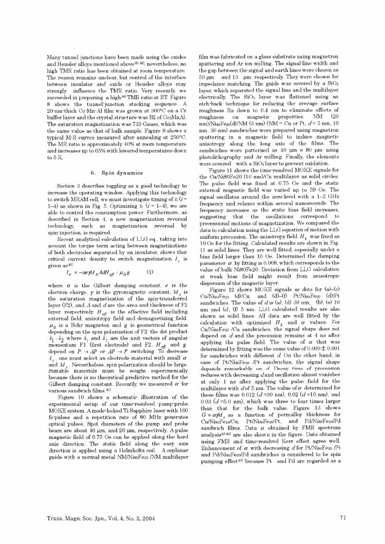
Many tunnel junctions have been made using the oxides
and Heusler alloys mentioned above35-38); nevertheless, no
high TMR ratio has been obtained at room temperature.
The reason remains unclear, but control of the interface
between insulator and oxide or Heusler alloys may
strongly influence the TMR ratio. Very recently, we
succeeded in preparing a high39)TMR ratio at RT. Figure
8 shows the tunnel-junction stacking sequence. A
20-nm-thick Co-Mn-Al film was grown at 300•Ž on a Cr
buffer layer and the crystal structure was B2 of Co2MnAl.
The saturation magnetization was 733 Gauss, which was
the same value as that of bulk sample. Figure 9 shows a
typical M-R curves measured after annealing at 250•Ž.
The MR ratio is approximately 40% at room temperature
and increases up to 65% with lowered temperatures down
to 5 K.
6. Spin dynamics
Section 3 describes toggling as a good technology to increase the operating window. Applying this technology to switch MRAM cell, we must investigate timing of ti (i= 1-4) as shown in Fig. 5. Optimizing ti (i = 1-4), we are able to control the consumption power. Furthermore, as described in Section 4, a new magnetization reversal technology, such as magnetization reversal by spin-injection, is required.
Recent analytical calculation of LLG eq., taking into account the torque term acting between magnetizations of both electrodes separated by an insulator, shows that critical current density to switch magnetization Ic is
given as40)(1)
where ƒ¿ is the Gilbert damping constant, e is the
electron charge, ƒÁ is the gyromagnetic constant, M s is
the saturation magnetization of the spin-transferred
layer (F2), ,and A and d are the area and thickness of F2
layer, respectively. H eff is the effective field including
external field, anisotropy field and demagnetizing field.
μB is a Bohr magneton and g is geometrical function
depending on the spin polarization of F2: the dot products1' s2 where s1 and s2 are the unit vectors of angular
momentum F1 (first electrode) and F2. H eff, and g
depend on P •¨ AP or AP •¨ P switching. TO decrease
I C , one must select an electrode material with small a
and Ms . Nevertheless, spin polarization should be large.
Suitable materials must be sought experimentally
because there is no theoretical predictive method for the
Gilbert damping constant. Recently, we measured a for
various sandwich films.41)
Figure 10 shows a schematic illustration of the
experimental setup of our time-resolved pump-probe
MORE system. A mode-locked Ti:Sapphire laser with 100
fs-pulses and a repetition rate of 80 MHz generates
optical pulses. Spot diameters of the pump and probe
beam are about 40 ƒÊm and 20 ƒÊm, respectively. A pulse
magnetic field of 0.75 Oe can be applied along the hard
axis direction. The static field along the easy axis
direction is applied using a Helmholtz coil. A coplanar
guide with a normal metal NM/Ni80Fe20 /NM multilayer
film was fabricated on a glass substrate using magnetron
sputtering and Ar ion milling. The signal-line width and
the gap between the signal and earth lines were chosen as
50 ƒÊm and 13 ƒÊm, respectively. They were chosen for
impedance matching. The guide was covered by a SiO2
layer, which separated the signal line and the multilayer
electrically. The SiO2 layer was flattened using an
etch-back technique for reducing the average surface
roughness Ra down to 0.4 nm to eliminate effects of
roughness on magnetic properties. NM (20
nm)/Ni80Fe20(d)/NM (3 nm) (NM = Cu or Pt, d = 5 nm, 10
nm, 30 nm) sandwiches were prepared using magnetron
sputtering in a magnetic field to induce magnetic
anisotropy along the long axis of the films. The
sandwiches were patterned as 40 ƒÊm x 80 ƒÊM using
photolithography and Ar milling. Finally, the elements
were covered with a SiO2layer to prevent oxidation.
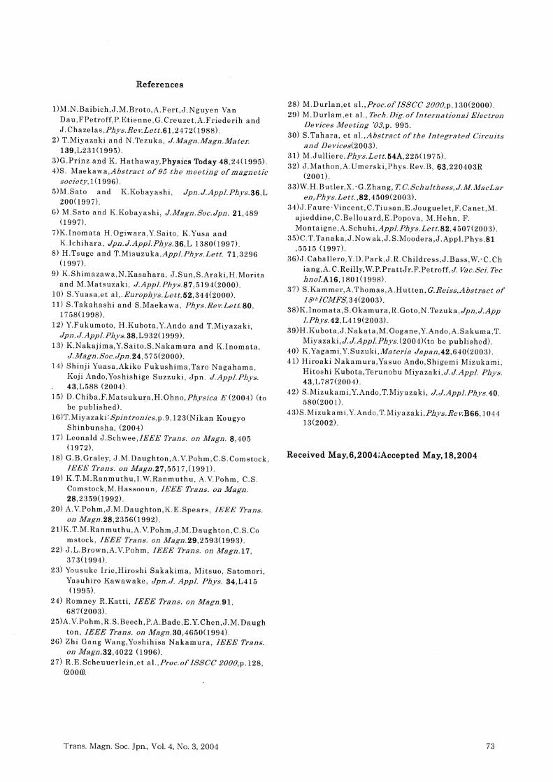
Figure 11 shows the time-resolved MORE signals for
the CuiNi80Fe20 (10 nm)/Cu multilayer as solid circles.
The pulse field was fixed at 0.75 Oe and the static
external magnetic field was varied up to 59 Oe. The
signal oscillates around the zero-level with a 1-2 GHz
frequency and relaxes within several nanoseconds. The
frequency increases as the static bias field increases,
suggesting that the oscillations correspond to
precessional motions of magnetization. We compared the
data to calculation using the LLG equation of motion with
uniform precession. The anisotropy field Hk was fixed as
10 Oe for the fitting. Calculated results are shown in Fig.
11 as solid lines. They are well fitted, especially under a
bias field larger than 10 Oe. Determined the damping
parameter a by fitting is 0.008, which corresponds to the
value of bulk Ni80Fe20. Deviation from LLG calculation
at weak bias field might result from anisotropic
dispersion of the magnetic layer.
Figure 12 shows MORE signals as dots for (a)-(c)-
Cu/Ni80Fe20 (d)/Cu, and (d)-(f) Pt/Ni80Fe20 (d)/Pt
sandwiches. The value of d is (a), (d) 30 nm, (b), (e) 10
nm and (c), (f) 5 nm. LLG calculated results are also
shown as solid lines. All data are well fitted by the
calculation with optimized Hk and a values. For
Cu/Ni80Fe20 /Cu sandwiches, the signal shape does not
depend on d and the precession remains at 4 ns after
applying the pulse field. The value of ƒ¿ that was
determined by fitting was the same value of 0.009 •} 0.001
for sandwiches with different d. On the other hand, in
case of Pt/Ni80Fe20 /Pt sandwiches, the signal shape
depends remarkably on d Decay time of precession
reduces with decreasing d and oscillation almost vanishes
at only 1 ns after applying the pulse field for the
multilayer with d of 5 nm. The value of a determined for
these films was 0.012 (d =30 nm), 0.02 (d =10 nm), and
0.03 (d =5.0 nm), which was three to four times larger
than that for the bulk value. Figure 13 shows
G = ƒ¿ƒÁMs as a function of permalloy thickness for
Cu/Ni80Fe20/Cu, Pt/Ni80Fe20/Pt, and Pd/Ni80Fe20/Pd
sandwich films. Data a obtained by FMR spectrum
analysis42-43) are also shown in the figure. Data obtained
using FAIR and time-resolved Kerr effect agree well.
Enhancement of a with decreasing d for Pt/Ni80Fe20 /Pt
and Pd/Ni80Fe20/Pd sandwiches is considered to be spin
pumping effect43) because Pt and Pd are regarded as a
Trans. Magn. Soc. Jpn., Vol. 4, No. 3, 2004 71

perfect spin sink. Theoretically, the enhancement of a by spin pumping is independent of the frequency of magnetic
precession. This work obtained the same a as FMR results. However, the local effect at the interface between
the Pt or Pd and Ni80Fe20 must be considered carefully for
quantitative comparison of damping enhancement. Detailed experiments and consideration of this matter
will be undertaken in other studies.
Fig. 10 Schematic illustration of the experimental
setup of a time-resolved pump-probe MOKE system.
Fig. 11 Time resolved MORE signals for the Cu/Ni80Fe20 (10 nm)/Cu sandwiches shown as solid circles. The pulse field was fixed at 0.75 Oe. The static external magnetic field was varied as shown in this figure. The calculated result using LLG equations of motion are also shown as solid lines.
(a)
(b)
(c)
(d)
(e)
(f)
Fig. 12 MOKE signals as dots for (a)-(c) sandwiches. d 30 nm for (a) and (d), 10 nm for (b) and (e), 5 nm for (c) and (f). LLG calculated results are also shown as solid lines.
Fig. 13 The Gilbert damping constant as a function of
NiFe thickness for Cu/NiFe/Cu, Pt/NiFe/Pt and
Pd/NiFe/Pd sandwiches. „O : measured using FMR,•™ :
measured using the Kerr effect.
Acknowledgements
Our study was supported by CREST of JST (Japan Science and Technology) and the IT-program of Research Revolution 2002 (RR2002) "Development of Universal Low-Power Spin Memory", and Grants-in-Aid for Scientific Research from the Ministry of Education, Culture, Sports, Science and Technology of Japan and the Strategic Information and Communications R&D Promotion Programme from the Ministry of Public Management, Home Affairs, Post and Telecommunications (MPHPT).
72 Trans. Magn. Soc. Jpn., Vol. 4, No. 3, 2004
References
1) M. N. Baibich, J. M. Broto, A. Fert, J. Nguyen Van
Dau, FPetroff, P. Etienne, G. Creuzet, A. Friederih and J. Chazelas, Phys. Rev. Lett. 61, 2472 (1988).
2) T.Miyazaki and N. Tezuka, J. Magn. Magn. Mater. 139, L231 (1995).
3) G. Prinz and K. Hathaway, Physics Today 48,24 (1995). 4)S. Maekawa,Abstract of 95 the meeting of magnetic
society, 1 (1996). 5) M. Sato and K.Kobayashi, Jpn.J. Appl. Phys. 36, L
200 (1997). 6) M. Sato and K. Kobayashi, J. Magn.Soc.Jpn . 21, 489
(1997). 7) K. Inomata H. Ogiwara, Y. Saito, K .Yusa and
K. Ichihara, Jpn.J. Appl. Phy s.36, L 1380 (1997). 8) H. Tsuge and T. Misuzuka, Appl. Phys. Lett. 71,3296
(1997). 9) K. Shimazawa, N. Kasahara, J. Sun, S. Araki, H. Morita
and M. Matsuzaki, J. Appl. Phys. 87, 5194 (2000). 10) S. Yuasa,et al,. Europhys, Lett. 52, 344(2000). 11) S. Takahashi and S. Maekawa, Phys. Rev. Lett. 80,
1758 (1998). 12) Y. Fukumoto, H. Kubota, Y. Ando and T. Miyazaki,
Jpn. J. Appl. Phys. 38, L932 (1999).
13) K.Nakajima,Y.Saito,S.Nakamura and K.Inomata ,J, Magn. Soc. Jpn. 24, 575 (2000).
14) Shinji Yuasa, Akiko Fukushima, Taro Nagahama, Koji Ando, Yoshishige Suzzuki, Jpn. J. Appl. Phys . 43, L588 (2004).
15) D. Chiba, F. Matsukura, H. Ohno, Physica E (2004) (to be published).
16) T. Miyazaki: Spintronics, p. 9, 123 (Nikan Kougyo Shinbunsha, (2004)
17) Leonald J. Schwee, IEEE Trans. on Magn . 8, 405 (1972).
18) G. B. Graley, J. M. Daughton, A. V. Pohm, C. S. Comstock, IEEE Trans. on Magn. 27, 5517, (1991).
19) K. T. M. Ranmuthu, I. W. Ranmuthu, A. V. Pohm, C. S. Comstock, M. Hassooun, IEEE Trans. on Magn. 28, 2359 (1992).
20) A. V. Pohm, J. M. Daughton, K. E. Spears, IEEE Trans. on Magn. 28, 2356 (1992).
21)K. T. M. Ranmuthu, A. V. Pohm, J. M. Daughton, C. S. Co mstock, IEEE Trans. on Magn.29,2593(1993).
22) J. L. Brown, A. V. Pohm, IEEE Trans. on Magn. 17, 373 (1994).
23) Yousuke Irie, Hiroshi Sakakima, Mitsuo, Satomori, Yasuhiro Kawawake, Jpn. J. Appl. Phys. 34, L415 (1995).
24) Romney R. Katti, IEEE Trans. on Magn. 91, 687 (2003).
25)A. V. Pohm, R. S. Beech, P. A. Bade, E. Y. Chen, J. M . Daugh ton, IEEE Trans. on Magn. 30, 4650 (1994).
26) Zhi Gang Wang, Yoshihisa Nakamura, IEEE Trans. on Magn. 32, 4022 (1996).
27) R. E. Scheuuerlein, et al., Proc. of ISSCC 2000, p. 128, (2000).
28) M. Durlan, et al., Proc. of ISSCC 2000, p. 130(2000). 29) M. Durlam, et al., Tech. Dig. of International Electron
Devices Meeting '03, p. 995. 30) S. Tahara, et al., Abstract of the Integrated Circuits
and Devices (2003). 31) M. Julliere, Phys. Lett. 54A, 225 (1975). 32) J. Mathon, A. Umerski, Phys. Rev. B, 63, 220403R
(2001). 33)W. H. Butler, X.-G. Zhang, T C. Schulthess, J. M. MacLar
en, Phys. Lett., 82, 4509 (2003). 34) J. Faure-Vincent, C. Tiusan, E. Jouguelet, F. Canet, M.
ajieddine, C. Bellouard, E. Popova, M. Hehn, F. Montaigne, A. Schuhi, Appl. Phys. Lett. 82, 4 507 (2003) .
35) C. T. Tanaka, J. Nowak, J. S. Moodera, J. Appl. Phys . 81 , 5515 (1997).
36) J. Caballero, Y. D. Park, J. R. Childress, J. Bass, W.-C. Ch iang, A. C. Reilly, W. P. PrattJr. F. Petroff, J. Vac. Sci. Tec hnol. A16, 1801 (1998).
37) S. Kammer, A. Thomas, A. Hutten, G. Reiss, Abstract of 18th ICMFS, 34 (2003).
38) K. Inomata, S. Okamura, R. Goto, N. Tezuka, Jpn, J. AppJ. Phys. 42, L419 (2003).
39) H. Kubota, J. Nakata, M. Oogane, Y. Ando, A. Sakuma,T. Miyazaki, J. J. ApplPhys. (2004) (to be published).
40) K. Yagami, Y. Suzuki, Materia Japan, 42, 640 (2003). 41) Hiroaki Nakamura, Yasuo Ando, Shigemi Mizukami,
Hitoshi Kubota, Terunobu Miyazaki, J. J. Appl. Phys. 43, L787 (2004).
42) S. Mizukami, Y. Ando, T. Miyazaki, J. J. Appl. Phys. 40, 580 (2001).
43) S. Mizukami, Y. Ando, T. Miyazaki, Phys. Rev. B66, 1044 13 (2002).
Received May, 6, 2004; Accepted May, 18, 2004
Trans. Magn. Soc. Jpn., Vol. 4, No. 3, 2004 73