Recent development in active phased array radar Phase ...faculty.utrgv.edu/zhijun.qiao/Lei-Qiao-IEEE...
19
Phase Adjustment and ISAR Imaging of Maneuvering Targets With Sparse Apertures LEI ZHANG, Member, IEEE JIA DUAN Xidian University China ZHI-JUN QIAO, Member, IEEE University of Texas–Pan American MENG-DAO XING, Member, IEEE ZHENG BAO, Life Senior Member, IEEE Xidian University China A multifunctional radar system can only acquire limited and discontinuous wideband pulses, which form sparse aperture (SA) observations of a target. To carry out radar activities (detection, tracking, and imaging) simultaneously for multiple targets, inverse synthetic aperture radar (ISAR) imaging exploiting these SA data is essential for multifunctional radar. In this paper, we study the phase adjustment and full-aperture (FA) reconstruction for SA-ISAR imaging of maneuvering targets. A modified eigenvector-based autofocus approach is proposed to correct phase errors within SA measurements of maneuvering targets. After phase correction, the FA data are reconstructed from SA measurements via sparse representation under a redundant chirp–Fourier dictionary. An efficient algorithm is developed to solve the sparse decomposition optimization, and ISAR images of the maneuvering target are obtained by adaptive joint time-frequency imaging approaches with the reconstructed data. Both simulated and real data sets are used to confirm the effectiveness of the proposed methods. Manuscript received February 23, 2013; revised July 21, 2013; released for publication November 5, 2013. DOI. No. 10.1109/TAES.2013.130115. Refereeing of this contribution was handled by C. Baker. This work was supported by the Fundamental Research Funds for the Central Universities under grant K5051302001 and K5051302078 and by the National Natural Science Foundation of China under Grant 61301280 and JJ0200122201. Authors’ addresses: Lei Zhang, Jia Duan, Meng-dao Xing, and Zheng Bao, Xidian University, National Lab of Radar Signal Processing, Taibai Road Num.2, Xi’an, Shann’xi 710071 China, E-mail: (zhanglei_0330@ 126.com); Zhi-jun Qiao, Department of Mathematics, University of Texas–Pan American, Edinburg, TX. 0018-9251/14/$26.00 C 2014 IEEE I. INTRODUCTION Recent development in active phased array radar techniques has enabled modern radar system to integrate multiple functions without increasing system complexity [1]. In the multifunctional radar system, the source of system time and power is optimally allocated for different tasks, such as searching, multitarget tracking, and imaging. Radar activities are usually executed simultaneously by using a periodic or nonperiodic time-sharing mechanism. In spite of great benefits, new challenges arise through use of these time-sharing mechanisms. For inverse synthetic aperture radar (ISAR) imaging acquiring a long and continuous wideband observation of a target is difficult because of its contention with other important tasks. For example, the radar beam needs to switch from among several directions to track multiple targets continuously and simultaneously. As a result, for each target, the wideband observation for ISAR imaging is limited and sparsely recorded. Multisourced interferences may also contaminate some portions of acquired data, yielding gaps. These incomplete data form sparse aperture (SA) measurements. Moreover, the SA measurements would be introduced in a netted radar system with multiple angular diversities [2, 3]. High-resolution ISAR imaging with limited SA measurements is essential to increase the flexibility and robustness of multifunctional radar. Recent studies show the suppression of discontinuous aperture effects on radar imagery, and many approaches have been proposed. Generally speaking, recently developed approaches may be sorted into four kinds: 1) Modern spectral estimate algorithms can effectively handle SA data. They estimate the complex-value amplitude and frequency of each sinusoidal signal component from gapped data by interpolating missing samples under certain constraints. Gapped-data amplitude and phase estimation [4, 5] algorithms are two of those representative approaches. 2) Prediction-based interpolation and extrapolation algorithms can solve the missing data problem in some situations where the available data are fitted into a linear prediction model. The missing data are recovered by the model coefficients and available observations [6–8]. 3) CLEAN techniques [9, 10] treat image formation from SA data as a deconvolution procedure. They estimate and subtract the main lobes of the strong scattering center responses iteratively until reaching convergence, which suppresses the high-gating lobes from missing data, to a certain degree. 4) Full-resolution imaging with SA can be converted into an optimization problem of sparse signal reconstruction, where the sparsity priority of the target scattering field is exploited to reconstruct the missing data [11–13]. Generally speaking, almost all currently existing methods for SA imaging deal with target echoes as multicomponent complex sinusoidal signals. For ISAR imaging, the sinusoidal signal assumption is only suitable for expressing the echo from a stable moving target within a relatively short coherent processing interval (CPI). ISAR IEEE TRANSACTIONS ON AEROSPACE AND ELECTRONIC SYSTEMS VOL. 50, NO. 3 JULY 2014 1955
Transcript of Recent development in active phased array radar Phase ...faculty.utrgv.edu/zhijun.qiao/Lei-Qiao-IEEE...
Phase Adjustment and ISARImaging of ManeuveringTargets With Sparse Apertures
LEI ZHANG, Member, IEEE
JIA DUANXidian UniversityChina
ZHI-JUN QIAO, Member, IEEEUniversity of Texas–Pan American
MENG-DAO XING, Member, IEEE
ZHENG BAO, Life Senior Member, IEEEXidian UniversityChina
A multifunctional radar system can only acquire limited anddiscontinuous wideband pulses, which form sparse aperture (SA)observations of a target. To carry out radar activities (detection,tracking, and imaging) simultaneously for multiple targets, inversesynthetic aperture radar (ISAR) imaging exploiting these SA data isessential for multifunctional radar. In this paper, we study the phaseadjustment and full-aperture (FA) reconstruction for SA-ISARimaging of maneuvering targets. A modified eigenvector-basedautofocus approach is proposed to correct phase errors within SAmeasurements of maneuvering targets. After phase correction, theFA data are reconstructed from SA measurements via sparserepresentation under a redundant chirp–Fourier dictionary. Anefficient algorithm is developed to solve the sparse decompositionoptimization, and ISAR images of the maneuvering target areobtained by adaptive joint time-frequency imaging approaches withthe reconstructed data. Both simulated and real data sets are used toconfirm the effectiveness of the proposed methods.
Manuscript received February 23, 2013; revised July 21, 2013; releasedfor publication November 5, 2013.
DOI. No. 10.1109/TAES.2013.130115.
Refereeing of this contribution was handled by C. Baker.
This work was supported by the Fundamental Research Funds for theCentral Universities under grant K5051302001 and K5051302078 and bythe National Natural Science Foundation of China under Grant 61301280and JJ0200122201.
Authors’ addresses: Lei Zhang, Jia Duan, Meng-dao Xing, and ZhengBao, Xidian University, National Lab of Radar Signal Processing, TaibaiRoad Num.2, Xi’an, Shann’xi 710071 China, E-mail: ([email protected]); Zhi-jun Qiao, Department of Mathematics, University ofTexas–Pan American, Edinburg, TX.
0018-9251/14/$26.00 C© 2014 IEEE
I. INTRODUCTION
Recent development in active phased array radartechniques has enabled modern radar system to integratemultiple functions without increasing system complexity[1]. In the multifunctional radar system, the source ofsystem time and power is optimally allocated for differenttasks, such as searching, multitarget tracking, and imaging.Radar activities are usually executed simultaneously byusing a periodic or nonperiodic time-sharing mechanism.In spite of great benefits, new challenges arise through useof these time-sharing mechanisms. For inverse syntheticaperture radar (ISAR) imaging acquiring a long andcontinuous wideband observation of a target is difficultbecause of its contention with other important tasks. Forexample, the radar beam needs to switch from amongseveral directions to track multiple targets continuouslyand simultaneously. As a result, for each target, thewideband observation for ISAR imaging is limited andsparsely recorded. Multisourced interferences may alsocontaminate some portions of acquired data, yieldinggaps. These incomplete data form sparse aperture (SA)measurements. Moreover, the SA measurements would beintroduced in a netted radar system with multiple angulardiversities [2, 3]. High-resolution ISAR imaging withlimited SA measurements is essential to increase theflexibility and robustness of multifunctional radar.
Recent studies show the suppression of discontinuousaperture effects on radar imagery, and many approacheshave been proposed. Generally speaking, recentlydeveloped approaches may be sorted into four kinds: 1)Modern spectral estimate algorithms can effectivelyhandle SA data. They estimate the complex-valueamplitude and frequency of each sinusoidal signalcomponent from gapped data by interpolating missingsamples under certain constraints. Gapped-data amplitudeand phase estimation [4, 5] algorithms are two of thoserepresentative approaches. 2) Prediction-basedinterpolation and extrapolation algorithms can solve themissing data problem in some situations where theavailable data are fitted into a linear prediction model.The missing data are recovered by the model coefficientsand available observations [6–8]. 3) CLEAN techniques[9, 10] treat image formation from SA data as adeconvolution procedure. They estimate and subtract themain lobes of the strong scattering center responsesiteratively until reaching convergence, which suppressesthe high-gating lobes from missing data, to a certaindegree. 4) Full-resolution imaging with SA can beconverted into an optimization problem of sparse signalreconstruction, where the sparsity priority of the targetscattering field is exploited to reconstruct the missing data[11–13]. Generally speaking, almost all currently existingmethods for SA imaging deal with target echoes asmulticomponent complex sinusoidal signals. For ISARimaging, the sinusoidal signal assumption is only suitablefor expressing the echo from a stable moving target withina relatively short coherent processing interval (CPI). ISAR
IEEE TRANSACTIONS ON AEROSPACE AND ELECTRONIC SYSTEMS VOL. 50, NO. 3 JULY 2014 1955
targets, such as flying planes and vessels on the sea, areusually noncooperative, and considerable maneuvering isinvolved in their motion, yielding time-varying Dopplermodulation in the echoed signal. To image themaneuvering target, signal components are modeled aschirps or high-order frequency-modulated signals [14–19].As a result, the assumption prevents current approachesfrom handling SA imaging of maneuvering targets. On theother hand, because of missing data within SA collections,current imaging approaches for a maneuvering targetdeveloped on the full-aperture (FA) data model, such asadaptive joint time-frequency analysis (AJTFA) [20–22],also fail to achieve ISAR images of high quality. To ourknowledge, there is not yet a straightforward approachcapable of accomplishing the task of high-resolutionSA-ISAR imaging of maneuvering targets, whichmotivates our work reported in this paper.
Motion error is one of the most challenging problemsin SA-ISAR imaging of maneuvering targets. Togetherwith translational motion, severe vibration of the target orradar platform could induce significant high-frequencymotion error in the received signal. The conventionalmotion compensation procedure for FA-ISAR data iscomposed of two independent steps: range alignment andphase adjustment [20]. Range alignment is the correctionof range migration between different pulses. After that,phase adjustment is necessary to remove the phase error,which is usually viewed as autofocus processing. As oneknows, some range alignment approaches are applicable toSA-ISAR data, such as the minimum entropy–basedmethod [23]. However, phase adjustment for SA-ISARdata is difficult when using straightforward autofocusmethods. Autofocus approaches inherently imply that thefocused image and the range-compressed phase historyconstitute a pair of Fourier transforms. This assumption isan intrinsic basis of conventional phase adjustmentapproaches, such as [24–27]. However, this assumptionfails in SA-ISAR imaging of maneuvering targets becauseof missing samples and the target movement, resulting infailure of most autofocus methods in SA cases. As anexception, eigenvector-based autofocus has been shown tobe applicable in SA-ISAR imaging of stable targets [23].Nevertheless, its performance dramatically degrades inSA-ISAR imaging of maneuvering targets because themaneuvering characteristics are not taken into account.Recently, some novel sparsity-driven methods [28–30]have also been proposed for phase correction in ISARimaging with sparsely sampled data. These approachesusually convert the joint image formation and phasecorrection with incomplete measurements into anoptimization problem of sparse representation, and thephase error is overcome in imaging processing in aniterative manner. Solving the optimization problemusually involves a large computation load, which may bean important obstacle in some real-time scenarios.
In this paper, we investigate robust and preciseSA-ISAR imaging of maneuvering targets and mainlyfocus on phase adjustment and FA signal reconstruction.
Based on the SA-chirp model, we develop an improvedeigenvector autofocus method that precisely corrects thephase error in SA data of maneuvering targets. In ourmethod, range cells containing dominant scatterers areselected to estimate the phase error in an iterative manner.Within the iteration, the first- and second-order phaseterms of these dominant range cells are adaptivelyremoved before the coherence matrix calculation foreigenvector autofocus processing; therefore, the negativeeffect from time-varying Doppler on phase errorestimation is eliminated. The second method lies in FAreconstruction of missing data by sparse representation.Because the major energy of the target scattering field iscontributed by a small number of scattering centers, thesignal components of the received data are very limited.Under a redundant SA chirp–Fourier basis, the signal ofeach range cell can be represented sparsely, which meansthat the coefficients of the signal are sparse. FA data canbe optimally reconstructed from SA data by solving anl1-norm optimization problem. The l1-norm optimizationfor sparse signal reconstruction is usually concerned incompressive sensing theory [31–33]. In this paper, anorthogonal matched-pursuit (OMP) algorithm isimplemented to solve the optimization of FA datareconstruction under the SA chirp–Fourier basis. Byadopting the recovered data, straightforward conventionalrotation compensation can be applied, andrange-instantaneous Doppler (RID) images ofmaneuvering targets are obtained by AJTFA approaches.Both the proposed phase adjustment and FA signalrecovery methods are extended so that migration throughrange cells (MTRC) induced by target rotational motion isnot nominal or to be neglected. Simulated and real datasets are utilized to confirm the effectiveness of theproposed methods in dealing with SA-ISAR imaging ofmaneuvering targets. Comparisons are also provided toshow the improvement of the modified autofocus method.
The paper is organized as follows. In Section II, theSA-ISAR signal model for maneuvering targets is brieflyintroduced. In Section III, we present the improvedeigenvector autofocus method. This section alsoformulates the optimization for FA data reconstruction inthe framework of sparse representation, and extensions toMTRC cases are discussed in detail. Section IV providesnumerical results to show the effectiveness and advantagesof the proposed methods. Finally, some conclusions aresummarized in the last section.
II. SA-ISAR SIGNAL MODEL FORMANEUVERING TARGETS
In this section, we first introduce the ISAR geometryand signal models for maneuvering targets withthree-dimensional rotation. Based on the ISAR geometry,the SA-ISAR signal model with phase error subsequentlyis developed.
Assuming the translational motion is corrected, theISAR geometry of a maneuvering target is represented by
1956 IEEE TRANSACTIONS ON AEROSPACE AND ELECTRONIC SYSTEMS VOL. 50, NO. 3 JULY 2014
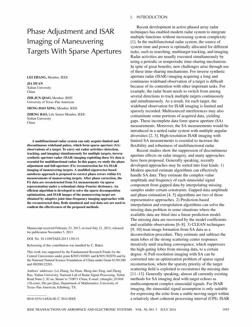
Fig. 1. ISAR geometry of maneuvering targets.
Fig. 1 [15]. XY Z defines a Cartesian coordinate with therotating center of the target. The imaging plane � isdetermined by vectors ω and R = [xR, yR, zR]T
(√
x2R + y2
R + z2R = 1), which represent the unit vectors of
the angular velocity of the target and the unit vector alongthe radar line of sight, respectively. Without loss ofgenerality, ω can be decomposed into ωe and ωR , whichcorrespond to the components perpendicular and parallelto R, respectively. Rotation from ωR does not cause radialmotion or Doppler modulation in the echoed signal,whereas rotation from ωe contributes all Dopplermodulation with respect to the synthetic aperture.Therefore, ωe is defined as the effective rotation. For theconvenience of the following derivation, we write theeffective rotational velocity as ωe = [
ωex, ωey, ωez
]T. The
symbol O stands for the origin of the coordinate system,which is actually the rotation center of the target. Let P bea scattering center with coordinate (x, y, z). For amaneuvering target, during the observation interval, itseffective rotation is generally nonuniform, which meansboth the magnitude and direction of ωe may be timevariant. The time variance of ωe for the maneuveringtarget can be expressed by the first-order approximation⎧⎪⎨
⎪⎩ωex ≈ ωx0 + αxtm
ωey ≈ ωy0 + αytm
ωez ≈ ωz0 + αztm
, (1)
where ω0 = [ωx0, ωy0, ωz0
]Tis the starting rotational
velocity, α = [αx, αy, αz
]Tis the vector of rotational
acceleration, and tm denotes the slow time. In thismaneuvering target model, the effective rotation velocityis time varying, which is the main difference betweenmaneuvering targets and stable ones. Assuming the radartransmits a signal with chirp waveform
sT (τ ) = rect
(τ
Tp
)· exp
(jπγ τ 2
), (2)
where τ denotes fast time, Tp is the pulse duration, and γ
is the chirp rate, after dechirping-on-receive and residuevideo phase compensation [15], we have the received
signal as
sp (τ, tm) = δp · rect
[τ − 2Rp (tm; x, y, z)
c
]
· exp
[−j
4π
cγ(τ − 2Rref (tm)
/c)�Rp (tm)
]
· exp
[−j
4π
λ�Rp (tm)
], (3)
where δp stands for the scattering coefficient, c is lightspeed, λ is the wavelength, and Rref (tm) is the referencerange at tm. The instantaneous range difference�Rp (tm) = Rp (tm) − Rref (tm) corresponds to rp • R. Byapplying the Fourier transform (FT) with respect to τ andneglecting the constants, we have the range-compressedsignal expression
sp (r, tm) = δp · sinc
[2γ Tp
c
(r − �Rp (tm)
)]
· exp
[−j
4π
λ�Rp (tm)
]. (4)
According to the 3D rotational model in Fig. 1, theradial range induced by the effective rotation can beexpressed by
�Rp (tm) =∫ tm
t0
(ωe × rp
) • Rdt. (5)
Substituting (1) into (5), we have
�Rp (tm) =∫ tm
t0
[ω0 • r + (α • r) tm]dtm
= (ω0 • r) tm + 1
2(α • r) t2
m
= aptm + 1
2bpt2
m + �rp (t0) , (6)
where ap = ω0 • r, bp = α • r, r = [(yzR − zyR),(zxR − xzR), (xyR − yxR)]T , and �rp (t0) is the range ofthe scattering center at time t0. Symbol “•” denotes the dotmultiplication of vectors. The orientation of ωe ischanging during CPI, leading to fluctuation of the imageplane. The rotational motion of the target is not known apriori. As a result, conventional range-Doppler (RD)imaging fails to deal with maneuvering targets. To handlethe problem of a time-varying image plane, adaptivetime–frequency representations are usually applied toachieve a sequence of target scattering projections on theinstantaneous Doppler planes, which forms RID images.
For clarity of the autofocus and FA reconstructionapproaches, we first assume that the MTRC induced byrotation can be neglected. Extensions to MTRC cases willbe discussed in the next section in detail. By substituting(6) into (4), we have
sp (r, tm) ≈ δp · sinc
[2B
c
(r − �rp (t0)
)]
· exp
[−j2π
(θp + fptm + 1
2γpt2
m
)], (7)
ZHANG ET AL.: ISAR IMAGING OF MANEUVERING TARGETS WITH SPARSE APERTURES 1957

Fig. 2. SA-ISAR signal geometry.
where θp = 2�rp(t0)λ
, fp = 2ap
λ, and γp = 2bp
λrepresent the
phase, Doppler frequency, and chirp rate, respectively.In the above signal model, we assume that the
translational motion is precisely compensated by rangealignment and phase adjustment. Despite the missingpulse, the range alignment approaches in [23, 34, 35] areapplicable. However, most of the autofocus approacheslose their efficacy in SA cases, because the vacantapertures break the FT relationship between therange-compressed data and the RD image. To complementthe real SA-ISAR case, the residual phase error must betaken into account. A certain range cell after rangecompression is given by
s (tm) =P∑
p=1
sp (tm) · exp [−j · φ (tm)]. (8)
We assume that the range cell contains P scatteringcenters, and the signal component of the pth scatteringcenter is still denoted by sp (tm) = δ′
p · exp[− j2π(
fptm + 12γpt2
m
) ]. In (8), φ (tm) represents the multisource
phase error at tm. For our convenience, we express thesignal in the discrete form
s(m)=P∑
p=1
sp (m) · exp [−j · φ (m)] 1 ≤ m ≤ M, (9)
where the FA data are assumed to contain a total of M
pulses. φ is an M-dimensional vector representing thephase error. Therefore, the signal of the pth scatteringcenter can be rewritten as
sp (m) = δ′p · exp
[−j2π
(fpm�T + 1
2γpm2�T 2
)]
1 ≤ m ≤ M. (10)
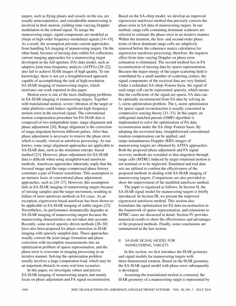
In the above context, we first introduce the signalmodel for maneuvering targets. Then, we extend it to theSA-ISAR cases. Because we consider that ISAR systemsobserve multiple moving targets simultaneously, radarillumination has to switch from one target to another veryfrequently, which leads to SA data for each target. Let therange cell be denoted still by the vector s. We assume K
SAs for a target consisting of a long aperture. Fig. 2 showsthe geometry of apertures. The FA data should contain M
pulses with an index from 1 to M. Suppose that the kth SAconsists of Lk pulses (whose index ranges from Nk + 1 toNk + Lk) represented by Ik = [Nk + 1 · · · Nk
+ Lk]TLk×1. Then, the vector corresponding to the kth SA
is given by
sk = [s (Nk + 1) s (Nk + 2) · · · s (Nk + Lk)
]TLk×1 .
(11)
Thus, the SA data vector corresponding to the rangebin is
s =
⎡⎢⎢⎢⎢⎢⎢⎢⎢⎣
s1
...
sk
...
sK
⎤⎥⎥⎥⎥⎥⎥⎥⎥⎦
M×1
. (12)
We note that the SA vector has M = L1 + L2 + · · ·+ LK (M < M) pulses. To clarify the expression,we define the index of pulses consisting of the validapertures in SA data as I = [
IT
1 · · · IT
K
]TM×1,
and the index of pulses corresponding to FA data asI = [
1 2 · · · M]TM×1 .
III. EIGENVECTOR-BASED AUTOFOCUSAND SIGNAL RECONSTRUCTION
A. Eigenvector-Based Autofocus for SA Dataof Maneuvering Targets
Together with time-variant Doppler, most existingautofocus approaches fail to remove the phase error in theSA data. However, there is one exception: theeigenvector-based autofocus method. It was first proposedin [36] and employed to correct phase error for compressedISAR imaging in [23]. Different from conventional phasecorrection, the method estimates the phase error from theeigenvector corresponding to the largest eigenvalue. It hasno requirement on the aperture pattern and is suitable toSA-ISAR imaging of nonmaneuvering targets. In thissection, we introduce some modifications to theeigenvector-based autofocus method in terms of phasecorrection for maneuvering targets with SAmeasurements. The modified eigenvector-based autofocusmethod includes the following steps:
1) Sample Selection: For a man-made target, somerange gates usually have dominant scattering centers.These range gates are optimal samples in theeigenvector-based autofocus approaches because of theirhigh signal-to-noise ratio (SNR), which makes theestimation more efficient and precise. The amplitude of a
1958 IEEE TRANSACTIONS ON AEROSPACE AND ELECTRONIC SYSTEMS VOL. 50, NO. 3 JULY 2014
range cell with a dominant scatterer has small variance.The minimum variance criteria for sample selection [24] isapplicable not only in conventional ISAR processing butalso in SA-ISAR cases. Contrast [35] also is another usefulselection criteria. Suppose N dominant range cells areselected, then the nth selected range cell may be given by
sn = δn ·
⎡⎢⎢⎢⎢⎢⎢⎢⎢⎢⎢⎣
e−j[2π(fn�T + 12 γn�T 2)+ϕ(1)]
...
e−j[2π(fnm�T + 12 γn(m�T )2)+ϕ(m)]
...
e−j[2π(fnM�T + 12 γn(M�T )2)+ϕ(M)]
⎤⎥⎥⎥⎥⎥⎥⎥⎥⎥⎥⎦
M×1
+ σ n m ∈ I, (13)
where δn represents the complex amplitude of the nthdominant range cell, σ n denotes a complex whiteGaussian noise, and fn, γn, and ϕ (m) stand for Dopplerfrequency, chirp rate, and the phase error in the mth pulse,respectively. The selected range cells are aligned into thefollowing matrix s :
s = [s1 · · · sn · · · sN
]M×N
+ �M×N. (14)
2) Doppler Frequency Compensation: For theselected range of cells, after zero-padding in the vacantapertures and Fourier transform, the Doppler cell with thestrongest response is circularly shifted to zero Doppler,which removes the Doppler offset. In this step, we firstfulfill the vacant apertures by padding zeros, and thenfollow with azimuth fast Fourier transform (FFT) to obtaina blurred RD image, where the Doppler bin with thestrongest response is determined. Because the Doppleroffset corresponds to a linear phase in the time domain,instead of using a circular shift to move the strongestresponse to the zero Doppler, we multiply thecorresponding linear phase function with the zero-paddedsignal in the time domain. The vacant apertures areremoved from the time domain data directly aftermultiplication. Assuming the Doppler frequency of eachdominant range cell is removed, the signal is given in theform
sn = δn ·
⎡⎢⎢⎢⎢⎢⎢⎢⎢⎢⎣
e−j[πγn�T 2+ϕ(1)]
...
e−j[πγn(m�T )2+ϕ(m)]
...
e−j[πγn(M�T )2+ϕ(M)]
⎤⎥⎥⎥⎥⎥⎥⎥⎥⎥⎦
M×1
+ σ n. (15)
It should be emphasized that in the beginningiterations, because of the presence of second-order phaseterms together with phase error, the precision of Dopplerfrequency removal is not as optimal as expected. However,with the increase in iteration number, both second-orderphase and phase error are suppressed at a low level, the
strong response can represent the Doppler offset of eachstrong scattering center, and its removal can be achievedaccurately. On the other hand, accurate Doppler offsetremoval feeds back to more precise phase error estimationin the following steps.
3) Second-Order Phase Compensation. Before thephase error estimation, the second-order phase terms ofselected strong scattering centers should be removedprecisely. After Doppler offset removal in the last step, sn
chirp rate γn is obtained by means of an exhaustive linearsearch over the variable γ in a predefined interval[γmin, γmax] . Maximum peak is used to determine anoptimal estimate, which is given by the optimization
〈γn〉 = maxγ
peak{FFT
{sn g (γ )
}}, (16)
where g (γ ) = [ejπγ�T 2 · · · ejπγ (M�T )2 ]T
M×1,
peak {•} denotes the maximum element of a vector, andFFT {·} is a discrete FFT operator for a vector. Aftercompensation of the second-order phase, the signal matrixcan be written as
sn = δn · θ M×1 + σ n, (17)
where θ M×1 = [e−jϕ(1) · · · e−jϕ(M)
]TM×1 is the
vector corresponding to the phase error. Therefore, thesample matrix can be rewritten as
s = [s1 · · · sn · · · sN
]M×N
= θ M×1 · (αN×1)T + �M×N, (18)
where αN×1 = [δ1 · · · δN
]N×1 is the amplitude
vector and �M×N is the noise matrix. This step issignificant for phase adjustment of SA data, by whichquadratic phase terms induced by target maneuvering arecorrected for all selected dominant scattering centers. As aresult, the interference of quadratic phase on the phaseerror estimate with the eigenvector-based approacheffectively is eliminated, yielding primary precisionimprovement of the phase adjustment.
4) Phase Error Estimate: In general, the variance ofnoise in each dominant range cell is assumed to follow an
identical distribution. Let C = 1N
SSH = 1N
N∑n=1
sn · (sn)H .
Then, the maximum likelihood estimation [9] of θ M×1
allows the choice of θ satisfying θH
θ = N andmaximizing the function
Q = θH
C θ =N∑
n=1
λn |zn|2, (19)
where the vector z = [z1 · · · zn · · · zN
]H= PH θ M×1, P is the eigenmatrix of C , and λ1 is theeigenvalue corresponding to z1 with λ1 ≥ λ2 · ·· ≥ λM.
Apparently, choosing θ = z1 maximizes Q. Phaseadjustment is achieved by applying the eigenvector tocorrect the phase error. Thus, the eigenvector method issuitable for compensating the phase error of the SA-ISARdata.
ZHANG ET AL.: ISAR IMAGING OF MANEUVERING TARGETS WITH SPARSE APERTURES 1959

5) Iterative Estimation and Correction: Phasecorrection of the selected range cells is performed throughthe phase error vector computed from the eigenvectorcorresponding to the maximum eigenvalue. Then steps 2,3, and 4 are repeated in sequence. In an iterative manner,because the image of dominant range cell trends to befocused, the response of an individual dominant pointbecomes more compact and SNR improves. The Dopplerfrequency and chirp rate estimation become more precise,which in turn enhances the accuracy of phase errorestimation with the eigenvector-based method. In general,convergence is achievable within only several iterations. Itshould be noted that using the original eigenvectorautofocus approach to perform coarse phase correction ishelpful in accelerating autofocus processing, and themodified eigenvector may be applied as a fine correction ina further step. In some cases in which the high-frequencyphase error is characteristic, coarse correction canaccelerate convergence of the proposed approacheffectively. Another significant aspect of the algorithm isthe stopping criteria of the iterative approach. As theestimate of phase error proceeds, Doppler frequencies andchirp rates of the samples tend to be more precise, and thelargest eigenvalue λ1 increases until convergence isachieved. One may assume it is accurate enough when thedifference between the largest eigenvalues of twosequential iterations is smaller than a predeterminedthreshold, such as 1 percent of λ1. To enhance therobustness of the eigenvector autofocus method in strongnoise circumstances, different weights can be added to theselected dominant range cells to encourage contributionfrom high-quality cells to the estimate [24].
Fig. 3 shows a clear flowchart of motion compensationfor SA-ISAR imaging of maneuvering targets. In theflowchart, the original and the proposed eigenvectorautofocus methods are performed in sequence. The formeris utilized for coarse phase compensation, and themodified method implements the fine correction.
B. Full-Aperture Signal Reconstruction From SA Data
In this section, we consider FA data reconstructionfrom SA data. After phase error correction, the SA signals for a range gate is rewritten as
s =P∑
p=1
sp + σ , (20)
where P scattering centers are assumed in the range cell,and the pth component is given by
sp (m) = δ′p · exp
[−j2π
(kp
m
M+ 1
2yp
m2
M2
)]m ∈ I .
(21)
Let γp = 1(M·�T )2 · yp and fp = 1
M·�T· kp. Clearly,
each signal component is a chirp with unknown Dopplerfrequency, chirp rate, and complex-value amplitude. Forour convenient derivation, let k and y stand for the
Fig. 3. Motion compensation for SA-ISAR data of maneuvering targets.
Doppler frequency and chirp rate, respectively; then, a SAchirp–Fourier basis can be constructed as
d (k, y) = 1√M
· Fk Cy (22)
Fk = [wk · · · wkm · · · wkM
]TM×1 (23)
Cy =[qy · · · qym2 · · · qyM2 ]T
M×1m ∈ I, (24)
where “” denotes Hadamard multiplication;w = exp
(−j 2πM
), q = exp
(−j πM2 �y
), and �y is the
grid step of the chirp rate. The Doppler series correspondsto [1 : M]TM×1(identical to I), and the chirp rate extends tothe vector y = [−Y/2 + 1 : Y/2]TY×1 · �y, where Y issupposed to be an even integer and selected so that yincludes the chirp rates of all signal components in (21).
1960 IEEE TRANSACTIONS ON AEROSPACE AND ELECTRONIC SYSTEMS VOL. 50, NO. 3 JULY 2014

We then have the SA chirp–Fourier dictionary as
D ={
d (1, 1) · · · d (M, 1)︸ ︷︷ ︸M
· · ·
· · · d (1, Y ) · · · d (M, Y )︸ ︷︷ ︸M
}M×(M·Y )
. (25)
In a condensed form, the SA signal of the range cellcan be rewritten as
s = Dw + σ . (26)
Our goal is to reconstruct the unknown vector w basedon the definite partial chirp–Fourier dictionary D and theSA vector s. It should be noted that the chirp-Fourierdictionary D is deterministic but not parametric, so we donot require the target rotational parameters a priori toconstruct the dictionary or to estimate them by exhaustivesearch before image formation. The key step is inestimating the optimal parameters yp, kp, and δp for eachsignal component, by which the FA signal can be easilyreconstructed. The ISAR imagery shows distribution ofthe target scattering field, where strong scattering centersusually take up only a fraction of whole image bins butcontribute the major energy. Therefore, such an ISARsignal is regarded as sparse. Moreover, as rangecompression is applied, the limited scatterers aredistributed over a set of range bins. Each range cellcontains only a few scatterers rather than all scatterers ofthe target. As a result, w presents strong sparsity. Suchsparsity is utilized to recover the high-dimension vector w
by an l1-norm optimization
〈ω〉 = arg minσ
‖w‖1 , s.t.∥∥s − Dw
∥∥2 ≤ ε, (27)
where ‖•‖1 denotes the l1-norm of a vector, and ε = ‖σ‖2is the noise term. The noise term can be estimated byrange bins containing pure noise [37]. One can see that theoptimization is composed of two different terms: thel2-norm constraint that preserves the data fidelity of thesolution and the l1-norm optimization that imposes mostlysmall elements, with a few large ones, in accordance withthe sparsity of the ISAR signal. The optimization problemcan be solved efficiently by some approaches [38–43].However, the high dictionary dimension leads to a greatcomputational load and memory requirement, whichhinders the application of currently existing algorithms inpractice. On the basis of the standard OMP algorithm, wedevelop an effective solver for the optimization problem(27). Implemented by FFT and interpolation, the solver isefficient and precise. The reconstruction and imagingprocedure takes the following steps.
1) We need to estimate the first chirp component of s,which is se1. Its Doppler frequency k1 and chirp rate y1
are achieved when the inner product of s and the basis inD reach its maximum; that is,
〈k1, y1〉 = maxk,y
∣∣d (k, y)H · s∣∣ . (28)
It is not difficult to understand that estimation of k1 andy1 is inherently limited to the grid resolution of D, namely,
Fig. 4. Illustration of grid refinement with interpolation. (a) Beforeinterpolation. (b) After interpolation.
the Doppler and chirp rate grids. However, if we decreasethe grid steps, then the dimension of D increases and leadsto computational inefficiency. For a discrete chirp–Fourierdictionary, the chirp rate step is suggested as �y = 1
M
[44]. The Doppler step unit is set to avoid ambiguity. Then,we apply FFT and interpolation to enhance both precisionand efficiency in the inner product computation. Supposethe inner product matrix corresponding to the dictionary is
IP (k, y) = d (k, y)H · s. (29)
Apparently, IP is an M × Y matrix. Instead ofcalculating its elements one by one, we may obtain a rowthrough the computation
IP (:, y) = FFT{
s Cy
}. (30)
Before we seek the maximum element in IP,interpolation is applied to refine its grid. Fig. 4 shows theinterpolation grid refinement for IP.
By the refined estimation of (k1, y1), we may achievethe signal estimate as
se1 = w1 · d (k1, y1) and w1 = d (k1, y1)H · s. (31)
ZHANG ET AL.: ISAR IMAGING OF MANEUVERING TARGETS WITH SPARSE APERTURES 1961

2) The residual signal is calculated by sres = s − se1.3) We use sres to find the next basis a (k2, y2) with the
maximum inner product criteria as shown in step 1. Then,a dictionary with two subspaces is obtained asD2 = [
d (k1, y1) , d (k2, y2)], and the corresponding
amplitude is estimated by w2 =[w1
w2
]= (
DH
2 D2)−1
DH
2 s, where w1 is renewed under D2. The second signalestimate is obtained by se2 = D2 · w2.
4) Steps 2 and 3 repeat until the energy of the residualsignal is below the noise level. Assume the procedure isimplemented by P ′ iterations. The estimated parametersinclude: a dictionary DP ′ corresponding to the P ′ signalcomponents, the amplitude vector wP ′ , and Doppler andchirp rate vectors kP ′ and yP ′ , which are given as
DP ′ = [d (k1, y1) d (k2, y2) · · · d (kP ′, yP ′)
]M×P ′ ,
(32a)
wP ′ = [w1 w2 · · · wP ′
]TP ′×1 , (32b)
kP ′ = [k1 k2 · · · kP ′
]TP×1 , (32c)
yP ′ = [y1 y2 · · · yP ′
]TP ′×1 . (32d)
5) After signal decomposition into the partialchirp–Fourier dictionary, with the above estimatedparameters, the FA signal can be reconstructed through theformulations
s =P ′∑
p=1
sp and sp (m) = wp
· exp
[−j2π
(kp
m
M+ 1
2yp
m2
M2
)]1 ≤ m ≤ M. (33)
By sparse decomposition under the chirp-Fourierdictionary, the amplitude, Doppler frequency, and chirprate of each scattering center are achieved simultaneously.Of course, the deterministic relationship between theDoppler parameters and target rotation variables in (6) isnot clear so far; however, the achievement of RID images isstraightforward. The time frequency (TF) slice of the rangebin may be computed through the Wigner–Ville distribution(WVD) [45] to each reconstructed signal component
T F =P ′∑
p=1
W V D{
sp
}. (34)
After the FA reconstruction for all range bins, their TFslices are arrayed to generate a sequence of RID images astraditional AJTFA-based ISAR images for maneuvering tar-gets. Of course, RID images generated with (34) are of highresolution and free of cross-terms, but the computationalload in (34) is relatively high. Efficient TF representations,such as adaptive optimal kernel TF representation [46], canbe used on the reconstructed signal s to leverage a balancebetween resolution and cross-terms in RID images.
C. Extensions to MTRC Cases
The above introduction of both the autofocus approachand FA reconstruction does not account for MTRC causedby rotation. In high-resolution ISAR imaging of targetswith large size, MTRC is usually present. Withaccommodation of some useful techniques, the negativeeffects of MTRC on the eigenvector autofocus and FAdata recovery can be overcome effectively.
To reduce the degradation of the eigenvector autofocusapproach in the presence of MTRC, we can perform thephase error estimation on the raw data at a lowerresolution by down-sampling. Down-sampling is first usedin [47] to reduce the influence of residual range cellmigration on the phase autofocus for SAR data. Herein,this process eliminates MTRC by summing severalneighboring range bins into a single bin. Also, theprocessing can be implemented by extracting only a partof the frequency band from the raw data to obtain therange-compressed data block [47], which is similar tosumming up processing. Combining adjacent range binsshould cover the range of MTRC. Then, range bin samplesare selected from the down-sampled SA data for phaseerror estimation, but phase compensation is performed onthe original SA data.
For maneuvering targets, the magnitude of MTRCdepends on the target size and rotation angle within CPI.In general, rotation-induced MTRC is restricted withinonly several range gates in real scenarios, because a smallrotation angle can be used to achieve high resolution inazimuth (e.g., ∼3–5 deg). Subband division processingmay be leveraged to reduce degradation of the SA datareconstruction when MTRC arises. In the FA datareconstruction after phase correction, the SA data are splitinto several subbands in the range frequency domain, andeach subband signal is transformed back into therange-compressed domain. Similar to down-samplingprocessing, MTRC is eliminated because of the decreaseof range resolution. Then, the FA data reconstruction ofeach subband is performed independently. The FA data ofan entire frequency band are constructed by combining therecovered FA subband data sets together. It should beemphasized that during the subband procedure, thefrequency band division is also deficient. As the resolutiondecreases in each subband signal, signal sparsity isreduced as well, since the number of scattering centerswithin a single range gate may increase. The SNR isdistinctively reduced, as well. The decrease in sparsity andSNR may degrade the performance of FA signalreconstruction. In this sense, the number of subbandsshould be preferred to suppress MTRC andsimultaneously retain the precision of FA reconstruction.Empirically, the rotation-induced MTRC is usually slight,and the frequency band of SA data can be separated intoseveral subbands. For example, we can separate the datainto four subbands, which indicates that the MTRCvarying within four range cells can be overcome by thesubband division. After reconstruction, MTRC should be
1962 IEEE TRANSACTIONS ON AEROSPACE AND ELECTRONIC SYSTEMS VOL. 50, NO. 3 JULY 2014

Fig. 5. Flowchart of FA reconstruction and RID imaging with subbanddivision.
compensated on the FA data. Keystone transform [48, 49]removes the linear MTRC on the reconstructed FA dataeffectively by eliminating the first-order coupling term inthe frequency domain. After the correction of MTRC,AJTFA algorithms are ready to generate RID images. Insummary, FA reconstruction with the subband techniquefor MTRC cases is illustrated by the flowchart in Fig. 5.
From the flowchart, one can find evident differences inthe proposed ISAR imaging procedure from ISARformations with conventional sparse representations.Instead of direct ISAR image formation from incompletemeasurements with the sparsity constraint optimization, inthe proposed scheme, FA data reconstruction from SAmeasurements is first performed via sparse representationunder a redundant chirp–Fourier dictionary, and thenconventional MTRC correction follows. Finally, the ISARimage of the maneuvering target is generated by usingAJTFA approaches through the reconstructed data. TheMTRC correction on the FA data plays a significant role inresolving the coupling between range and azimuth
dimensions. Moreover, because both FA reconstructionand AJTFA imaging are performed in azimuth, the wholeSA-ISAR imaging scheme involves only one-dimensionalsparse decomposition, not two-dimensional (2D)decomposition as in other sparse decomposition–basedimaging algorithms [50, 51], yielding efficiencyenhancement at a possible price of precision loss. Anothersignificant reason why conventional AJTFA imaging isrequired in our scheme is because, as Fig. 1 shows, theeffective rotational vector of maneuvering targets istime-varying during the CPI. Conventional RD imagingapproaches are based on a 2D rotation model; that is, theeffective rotational vector is fixed during the CPI, which isnot suitable for maneuvering cases. However, AJTFAimaging can generate a sequence of RID images to adjustthe change in direction of image planes during the CPI,and the RID images also pave a possible way to analyzingthe aspect change of target during CPI.
IV. EXPERIMENTS
A. Simulated Data Description
This subsection comprises two parts. First, we analyzethe performance of the proposed eigenvector autofocusapproach for the SA-ISAR data of maneuvering targetsand compare with the original eigenvector method.Second, the FA data reconstruction is tested, and itsperformance metrics are evaluated.
The data set applied in this subsection is the B727plane data simulated by the Naval Research Lab. Someradar system parameters are listed as follows: The centerfrequency is 9 GHz, the pulse repeat frequency is 20 kHz,the FA data set consists of 256 pulses in total, and thesignal bandwidth is 150 MHz. The range profiles arepresented in Fig. 6(a). Considerable maneuvering causesserious blurring of the RD image, as shown in Fig. 6(b).From Fig. 6(a), one can note that explicit MTRC arises inthe range-compressed data. In the following experiments,the frequency band of SA data is divided into foursubbands in the FA data reconstruction with sparserepresentation to reduce the negative effects from MTRC.The original data set is free of phase noise. SA-ISAR datawith different SNRs (from 0 to 20 dB) are generated byextracting pulses from the original data set and addingcomplex white Gaussian noise. Herein, SNR is defined asthe ratio of signal energy and noise energy.
In some special situations, multisource phase error hassubstantial high-frequency properties. For example, severevibration of both the target or radar platform together withjetting of analog/digital sampling and signal transmissioncould cause random phase errors. Of all type of phaseerrors, random errors are the most complicated and severe,and usually the most difficult to correct. To show therobustness of the eigenvector-based autofocus approaches,random phase is added (see Fig. 7) in all experiments.
To evaluate the performance of phase error estimation,the standard deviation between the estimated and the
ZHANG ET AL.: ISAR IMAGING OF MANEUVERING TARGETS WITH SPARSE APERTURES 1963

Fig. 6. Simulated B727 data. (a) Aligned range profiles. (b) RD imagewith serious blur.
Fig. 7. Added random phase error (unit is radian).
actual added phase error is used, as in
STD = std[θ − θ
], (35)
where std [•] denotes the operator calculating the standarddeviation of a vector. The performance of FA
Fig. 8. Sparse aperture patterns. (a) SA-1. (b) SA-2.
reconstruction is evaluated by two factors: noiseinterference and pulse number. To provide a quantitativeevaluation for the performance of the FA reconstruction,we view the coherence coefficient of the reconstructionand the original data as a metric, which is defined as
Rcoef =⟨S S
⟩|S|F ·
∣∣∣S∣∣∣F
, (36)
where S and S denote the original FA and reconstructed FAdata sets, respectively, and the symbol 〈·〉 is the operatorfor summing up all components of a matrix. Apparently,when Rcoef is close to 1, the FA data reconstruction isoptimal and close to the ideal signal, whereas low Rcoef
indicates serious reconstruction degradation.
B. Performance Versus SNR
The aim of the first experiment is to analyze theinfluence of SNR on the performance of the variousapproaches. To compare noise tolerance of the originaleigenvector and the proposed autofocus approaches, weconsider three different aperture patterns: full aperture,random sampled SA (SA-1), and block sampled SA(SA-2). SA-1 and SA-2 are shown in Figs. 8(a) and 8(b),
1964 IEEE TRANSACTIONS ON AEROSPACE AND ELECTRONIC SYSTEMS VOL. 50, NO. 3 JULY 2014
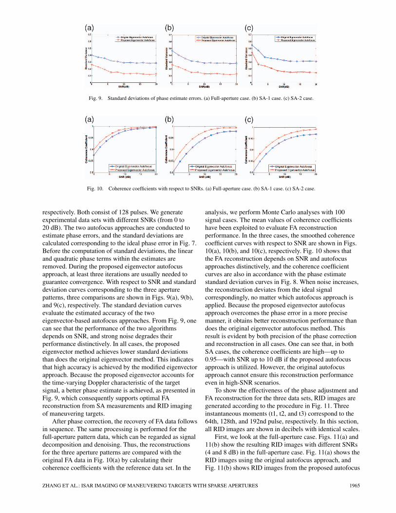
Fig. 9. Standard deviations of phase estimate errors. (a) Full-aperture case. (b) SA-1 case. (c) SA-2 case.
Fig. 10. Coherence coefficients with respect to SNRs. (a) Full-aperture case. (b) SA-1 case. (c) SA-2 case.
respectively. Both consist of 128 pulses. We generateexperimental data sets with different SNRs (from 0 to20 dB). The two autofocus approaches are conducted toestimate phase errors, and the standard deviations arecalculated corresponding to the ideal phase error in Fig. 7.Before the computation of standard deviations, the linearand quadratic phase terms within the estimates areremoved. During the proposed eigenvector autofocusapproach, at least three iterations are usually needed toguarantee convergence. With respect to SNR and standarddeviation curves corresponding to the three aperturepatterns, three comparisons are shown in Figs. 9(a), 9(b),and 9(c), respectively. The standard deviation curvesevaluate the estimated accuracy of the twoeigenvector-based autofocus approaches. From Fig. 9, onecan see that the performance of the two algorithmsdepends on SNR, and strong noise degrades theirperformance distinctively. In all cases, the proposedeigenvector method achieves lower standard deviationsthan does the original eigenvector method. This indicatesthat high accuracy is achieved by the modified eigenvectorapproach. Because the proposed eigenvector accounts forthe time-varying Doppler characteristic of the targetsignal, a better phase estimate is achieved, as presented inFig. 9, which consequently supports optimal FAreconstruction from SA measurements and RID imagingof maneuvering targets.
After phase correction, the recovery of FA data followsin sequence. The same processing is performed for thefull-aperture pattern data, which can be regarded as signaldecomposition and denoising. Thus, the reconstructionsfor the three aperture patterns are compared with theoriginal FA data in Fig. 10(a) by calculating theircoherence coefficients with the reference data set. In the
analysis, we perform Monte Carlo analyses with 100signal cases. The mean values of coherence coefficientshave been exploited to evaluate FA reconstructionperformance. In the three cases, the smoothed coherencecoefficient curves with respect to SNR are shown in Figs.10(a), 10(b), and 10(c), respectively. Fig. 10 shows thatthe FA reconstruction depends on SNR and autofocusapproaches distinctively, and the coherence coefficientcurves are also in accordance with the phase estimatestandard deviation curves in Fig. 8. When noise increases,the reconstruction deviates from the ideal signalcorrespondingly, no matter which autofocus approach isapplied. Because the proposed eigenvector autofocusapproach overcomes the phase error in a more precisemanner, it obtains better reconstruction performance thandoes the original eigenvector autofocus method. Thisresult is evident by both precision of the phase correctionand reconstruction in all cases. One can see that, in bothSA cases, the coherence coefficients are high—up to0.95—with SNR up to 10 dB if the proposed autofocusapproach is utilized. However, the original autofocusapproach cannot ensure this reconstruction performanceeven in high-SNR scenarios.
To show the effectiveness of the phase adjustment andFA reconstruction for the three data sets, RID images aregenerated according to the procedure in Fig. 11. Threeinstantaneous moments (t1, t2, and t3) correspond to the64th, 128th, and 192nd pulse, respectively. In this section,all RID images are shown in decibels with identical scales.
First, we look at the full-aperture case. Figs. 11(a) and11(b) show the resulting RID images with different SNRs(4 and 8 dB) in the full-aperture case. Fig. 11(a) shows theRID images using the original autofocus approach, andFig. 11(b) shows RID images from the proposed autofocus
ZHANG ET AL.: ISAR IMAGING OF MANEUVERING TARGETS WITH SPARSE APERTURES 1965
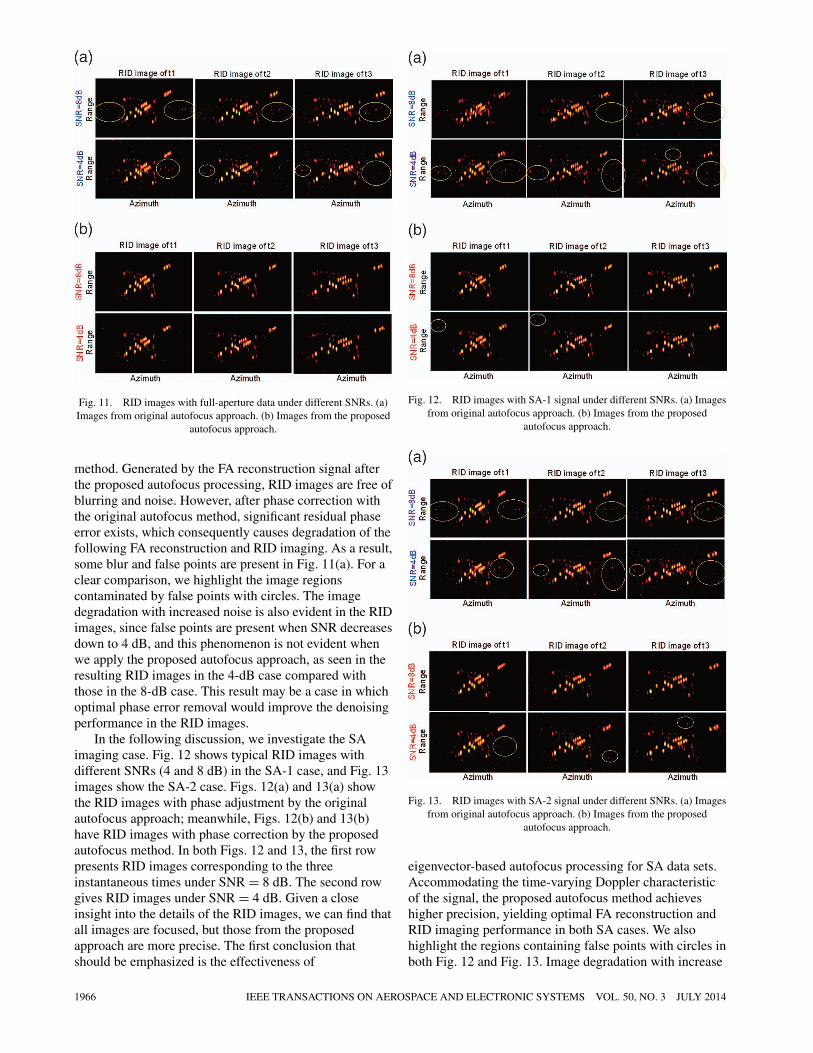
Fig. 11. RID images with full-aperture data under different SNRs. (a)Images from original autofocus approach. (b) Images from the proposed
autofocus approach.
method. Generated by the FA reconstruction signal afterthe proposed autofocus processing, RID images are free ofblurring and noise. However, after phase correction withthe original autofocus method, significant residual phaseerror exists, which consequently causes degradation of thefollowing FA reconstruction and RID imaging. As a result,some blur and false points are present in Fig. 11(a). For aclear comparison, we highlight the image regionscontaminated by false points with circles. The imagedegradation with increased noise is also evident in the RIDimages, since false points are present when SNR decreasesdown to 4 dB, and this phenomenon is not evident whenwe apply the proposed autofocus approach, as seen in theresulting RID images in the 4-dB case compared withthose in the 8-dB case. This result may be a case in whichoptimal phase error removal would improve the denoisingperformance in the RID images.
In the following discussion, we investigate the SAimaging case. Fig. 12 shows typical RID images withdifferent SNRs (4 and 8 dB) in the SA-1 case, and Fig. 13images show the SA-2 case. Figs. 12(a) and 13(a) showthe RID images with phase adjustment by the originalautofocus approach; meanwhile, Figs. 12(b) and 13(b)have RID images with phase correction by the proposedautofocus method. In both Figs. 12 and 13, the first rowpresents RID images corresponding to the threeinstantaneous times under SNR = 8 dB. The second rowgives RID images under SNR = 4 dB. Given a closeinsight into the details of the RID images, we can find thatall images are focused, but those from the proposedapproach are more precise. The first conclusion thatshould be emphasized is the effectiveness of
Fig. 12. RID images with SA-1 signal under different SNRs. (a) Imagesfrom original autofocus approach. (b) Images from the proposed
autofocus approach.
Fig. 13. RID images with SA-2 signal under different SNRs. (a) Imagesfrom original autofocus approach. (b) Images from the proposed
autofocus approach.
eigenvector-based autofocus processing for SA data sets.Accommodating the time-varying Doppler characteristicof the signal, the proposed autofocus method achieveshigher precision, yielding optimal FA reconstruction andRID imaging performance in both SA cases. We alsohighlight the regions containing false points with circles inboth Fig. 12 and Fig. 13. Image degradation with increase
1966 IEEE TRANSACTIONS ON AEROSPACE AND ELECTRONIC SYSTEMS VOL. 50, NO. 3 JULY 2014

Fig. 14. Standard deviations with respect to NOPs. (a) SA-1 case. (b)SA-2 case.
in noise is also evident in the RID images, especially withthe original autofocus method when SNR decreases downto 4 dB. Nevertheless, the high quality of RID imagesgenerated by the proposed autofocus method remainswhen noise increases, which is very close to that in the FAdata case.
C. Performance Versus Pulse Number
We now investigate how the sample amount affectsrecovery performance. We test the reconstructed results ofthe two SA patterns by varying the number of pulses(NOP). With different numbers of pulses and constantSNR (8 dB), we first correct the SA data sets by theproposed eigenvector autofocus method and thenreconstruct the FA signal and RID images. The pulsenumber is set to decrease from 196 to 60. The standarddeviation curves reveal the estimate accuracy of the twoeigenvector-based autofocus approaches, as shown inFig. 14, and the coherent coefficient curves are shown inFig. 15. One can see that, with relatively high SNR, ahighly coherent coefficient is achievable, which indicatesoptimal recovery in both SA cases, and the reconstructedFA signal is closer to the ideal data. This phenomenon is
Fig. 15. Coherence coefficients with respective to NOPs. (a) SA-1 case.(b) SA-2 case.
not explicit when the pulse amount is small, such as NOP= 60, because the coherence coefficient decreases down toa small value.
Figs. 16 and 17 show typical RID images with twodifferent SA pulse amounts (108 and 60), by which weinvestigate the performance of approaches with specificpulse numbers. By comparing Figs. 16 and 17, in all cases,the proposed approaches are capable of preciselyreconstructing the FA signal and generating RID imageswith high quality in both SA patterns. Inspecting Figs. 16and 17, we find that although the original eigenvectorautofocus approach works in both SA cases, itsperformance may be still unacceptable simply because theerror and false points (highlighted by circles) degrade theRID image to some degree. We can make this inferencebecause the focal quality of the RID image of themaneuvering target obtained using the proposed phaseadjustment and FA reconstruction is satisfactory. Theseresults indicate that the proposed phase correctionsuppresses phase error optimally by considering thetime-varying Doppler of the target signal and is suitablefor generating high-quality RID images by combining theFA reconstruction based on sparse representation.
ZHANG ET AL.: ISAR IMAGING OF MANEUVERING TARGETS WITH SPARSE APERTURES 1967

Fig. 16. SA-1 RID images under different pulse numbers (in decibels).(a) Original eigenvector autofocus. (b) Proposed eigenvector autofocus.
Fig. 17. SA-2 RID images under different pulse numbers (in decibels).(a) Original eigenvector autofocus. (b) Proposed eigenvector autofocus.
D. Real Data Experiments
In this subsection, real, measured data are utilized totest the performance of the proposed methods. The dataset of a Yak-42 airplane is recorded by a C-band(5.52 GHz) ISAR experimental system. The transmittingsignal is a 400-MHz linear modulated chirp signal. Thereceived signal is dechirped and I/Q sampled. In this dataset, the pulse repetition frequency is 100 Hz (i.e., 256pulses are used). Range alignment is performed to removethe range shift induced by translational motion in advance.
Fig. 18. Yak-42 data and RD image. (a) Aligned range profiles.(b) RD image.
Significant movement is involved during targetmaneuvering. As a result, not only time-varying Dopplerbut also explicit MTRC are induced in the recorded data.The aligned profiles are shown in Fig. 18(a), where MTRCcan be inspected clearly. The RD image generated by all256 pulses after phase correction with the eigenvectorautofocus is shown in Fig. 18(b). Maneuvering duringobservation causes evident RD image smearing. Theoriginal recorded data has considerable noise, so we do notadd any synthesized noise into the data. SA data sets with128 pulses are generated by extracting pulses from theoriginal data. A random sampled SA pattern is assumed.In FA reconstruction processing, data sets are divided intofour subbands in the frequency domain to reduce thenegative effect from MTRC. Keystone transform isapplied to the reconstructed FA data for MTRC removalbefore RID image processing. At first, we investigate theautofocus performance of both the original and proposedeigenvector approaches with the full aperture data. TheAJTFA RID images corresponding to the threeinstantaneous moments are provided in Figs. 19(a) and19(b). Their image contrast and entropy are also calculatedto investigate focal performance. The effectiveness of
1968 IEEE TRANSACTIONS ON AEROSPACE AND ELECTRONIC SYSTEMS VOL. 50, NO. 3 JULY 2014
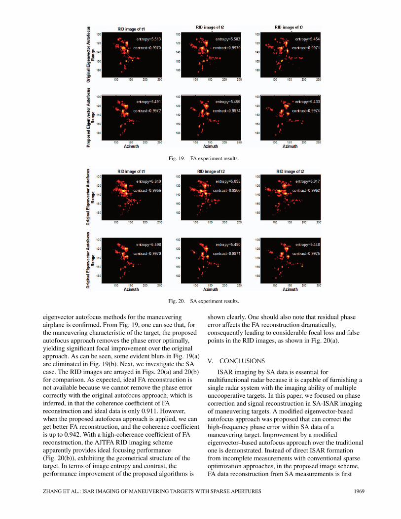
Fig. 19. FA experiment results.
Fig. 20. SA experiment results.
eigenvector autofocus methods for the maneuveringairplane is confirmed. From Fig. 19, one can see that, forthe maneuvering characteristic of the target, the proposedautofocus approach removes the phase error optimally,yielding significant focal improvement over the originalapproach. As can be seen, some evident blurs in Fig. 19(a)are eliminated in Fig. 19(b). Next, we investigate the SAcase. The RID images are arrayed in Figs. 20(a) and 20(b)for comparison. As expected, ideal FA reconstruction isnot available because we cannot remove the phase errorcorrectly with the original autofocus approach, which isinferred, in that the coherence coefficient of FAreconstruction and ideal data is only 0.911. However,when the proposed autofocus approach is applied, we canget better FA reconstruction, and the coherence coefficientis up to 0.942. With a high-coherence coefficient of FAreconstruction, the AJTFA RID imaging schemeapparently provides ideal focusing performance(Fig. 20(b)), exhibiting the geometrical structure of thetarget. In terms of image entropy and contrast, theperformance improvement of the proposed algorithms is
shown clearly. One should also note that residual phaseerror affects the FA reconstruction dramatically,consequently leading to considerable focal loss and falsepoints in the RID images, as shown in Fig. 20(a).
V. CONCLUSIONS
ISAR imaging by SA data is essential formultifunctional radar because it is capable of furnishing asingle radar system with the imaging ability of multipleuncooperative targets. In this paper, we focused on phasecorrection and signal reconstruction in SA-ISAR imagingof maneuvering targets. A modified eigenvector-basedautofocus approach was proposed that can correct thehigh-frequency phase error within SA data of amaneuvering target. Improvement by a modifiedeigenvector–based autofocus approach over the traditionalone is demonstrated. Instead of direct ISAR formationfrom incomplete measurements with conventional sparseoptimization approaches, in the proposed image scheme,FA data reconstruction from SA measurements is first
ZHANG ET AL.: ISAR IMAGING OF MANEUVERING TARGETS WITH SPARSE APERTURES 1969
performed via sparse representation under a redundantchirp–Fourier dictionary. Then, conventional MTRCcorrection can be applied to the FA data. Finally, an ISARimage of the maneuvering target is generated by AJTFAapproaches through the reconstructed data. This procedureis flexible and efficient for imaging maneuvering targets inreal scenarios. Both simulated and real data experimentsvalidate the effectiveness of the proposed approaches forthe SA-ISAR imaging of maneuvering targets. Finally, itshould be pointed out that sparse decomposition paves apotential way to bridge the Doppler parameters to targetrotation during RID image formation. And if adeterministic relationship between them can be developed,rotation estimation and azimuth scaling for a maneuveringtarget image is possible. Some important problems, suchas shadow and amplitude modulation in signal modeling,are ignored, which limits application of the proposedmethod in some real scenarios. These problems will beinvestigated in the near future.
ACKNOWLEDGMENT
The authors thank the anonymous reviewers for theirvaluable comments to improve the quality of this paper.
REFERENCES
[1] Herd, J., Duffy, S., Webar, M., Brigham, G., Weigand, C., andCursio, D.Low cost multifunction phased array radar concept.In Proceedings of the 2010 IEEE International Symposium onPhased Array Systems and Technology (ARRAY), Lexington,MA, Oct. 12–15, 2010, 457–460.
[2] Pastina, D., Bucciarelli, M., and Lombardo, P.Multistatic and MIMO Distributed ISAR for EnhancedCross-Range Resolution of Rotating Targets.IEEE Transactions on Geoscience and Remote Sensing, 48, 8(Aug. 2010), 3300–3317.
[3] Larsson, E. G., Liu, G. Q., Stoica, P., and Li, J.High-resolution SAR imaging with angular diversity.IEEE Transactions on Aerospace and Electronic Systems, 37,4 (Oct. 2001), 1359–1372.
[4] Larsson, E. G., Stoica, P., and Li, J.Amplitude spectrum estimation for two-dimensional gappeddata.IEEE Transactions on Signal Processing, 50, 6 (June 2002),1343–1353.
[5] Larsson, E. G., and Li, J.Spectral analysis of periodically gapped data.IEEE Transactions on Aerospace and Electronic Systems, 39,3 (July 2003), 1089–1097.
[6] Li, H. J., Farhat, N. H., and Shen, Y. S.A new iterative algorithm for extrapolation of data available inmultiple restricted regions with applications to radar imaging.IEEE Transactions on Antennas. Propagation, AP-35, 5 (May1987), 581–588.
[7] Cabrera, S. D. and Parks, T. W.Extrapolation and spectral estimation with iterative weightednorm modification.IEEE Transactions on Signal Processing, 39, 4 (Apr. 1991),842–851.
[8] Xu, X., Huang, P. and Feng, X.An iterative algorithm for ultra wideband radar imaging fromrandomly fragmented spectral data.In Proceedings of the SEE 2004 Radar Conference, Toulouse,France, Oct. 2004.
[9] Tsao, J., and Steinberg, B. D.Reduction of sidelobe and speckle artifacts in microwaveimaging: the CLEAN technique.Transactions on Antennas and Propagation, 36, 4 (Apr. 1988),543–566.
[10] Bose, R.A., Freeman, A., and Steinberg, B. D.Sequence CLEAN: a modified deconvolution technique formicrowave images of contiguous targets.IEEE Transactions on Aerospace and Electronic Systems, 38,1 (Jan. 2002), 89–96.
[11] Cetin, M. and Moses, R. L.SAR imaging from partial-aperture data with frequency-bandomissions.In Proceedings of SPIE Defense and Security Symposium,Algorithm for Synthetic Aperture Radar Imaging XII,Orlando, FL, Mar. 2005.
[12] Zhang, B. C., Hong, W., and Wu, Y. R.Sparse microwave imaging: Principles and applications.Science China Information Sciences, 55, 8 (2012),1722–1754.
[13] Onhon, N. O., and Cetin, M.A nonquadratic regularization-based technique for joint SARimaging and model error correction.In Proceedings of SPIE, Algor. Synthetic Aperture RadarImagery XVI, vol. 7337, article 73370C, 2009, 10 p.
[14] Bao, Z., Wang, G., and Luo, L.Inverse synthetic aperture radar imaging of maneuveringtargets.Optical Engineering, 37, 5 (May 1998), 1582–1588.
[15] Wu, L., Wei, X. Z., Yang, D. G., Wang, H.Q., and Li, X.ISAR Imaging of Targets With Complex Motion Based onDiscrete Chirp Fourier Transform for Cubic Chirps.IEEE Transactions on Geoscience and Remote Sensing, 50, 10(Oct. 2012), 4202–4212.
[16] Wang, Y., and Jiang, Y.ISAR imaging of a ship target using product high ordermatched-phase transform.IEEE Geoscience and Remote Sensing Letters, 6, 4 (Oct.2009), 658–661.
[17] Bao, Z., Sun, C. Y., and Xing, M. D.Time-frequency approaches to ISAR imaging of maneuveringtargets and limitations.IEEE Transactions on Aerospace and Electronic Systems, 37,3 (July 2001), 1092–1099.
[18] Berizzi, F., Mese, E. D., Diani, M., and Martorella, M.High-resolution ISAR imaging of maneuvering targets bymeans of the range instantaneous Doppler technique:modeling and performance analysis.IEEE Transactions on Image Processing, 10, 12 (Dec. 2001),1880–1890.
[19] Li, Y. C., Wu, R., Xing, M., and Bao, Z.Inverse synthetic aperture radar imaging of ship target withcomplex motion.IET Radar, Sonar, and Navigation, 2, 6 (Dec. 2008), 395–403.
[20] Chen, V. C., and Ling, H.Time–Frequency Transform for Radar Imaging and SignalAnalysis. Boston: Artech House, 2002.
[21] Wang, Y., Ling, H., and Chen, V. C.ISAR motion compensation via adaptive joint time-frequencytechnique.IEEE Transactions on Aerospace and Electronic Systems, 34,2 (1998), 670–677.
[22] Thayaparan, T., Lampropoulos, G., Wong, S. K., andRiseborough, E.Application of adaptive time-frequency algorithm for focusingdistorted ISAR images from simulated and measured radardata.IEE Proceedings—Radar, Sonar, and Navigation, 150, 4(2003), 213–220.
1970 IEEE TRANSACTIONS ON AEROSPACE AND ELECTRONIC SYSTEMS VOL. 50, NO. 3 JULY 2014
[23] Zhu, D., Yu, X., and Zhu, Z.Algorithms for Compressed ISAR Autofocusing.In Proceedings of 2011 IEEE CIE International Conferenceon Radar, Chengdu, China, 533–536, Oct. 24–27, 2011.
[24] Ye, W., Yeo, T. S., and Bao, Z.Weighted Least-Squares estimation of phase errors forSAR/ISAR autofocus.IEEE Transactions on Geoscience and Remote Sensing, 37, 5(Sep 1999), 2487–2494.
[25] Berizzi, F., and Cosini, G.Autofocusing of inverse synthetic aperture radar images usingcontrast optimization.IEEE Transactions on Aerospace and Electronic Systems, 32,3 (Jul. 1996), 1185–1191.
[26] Martorella, M., Berizzi, F., and Haywood, B.Contrast maximisation based technique for 2-D ISARautofocusing.Proceedings of the IEEE—Radar, Sonar, and Navigation, 152,4 (Aug. 2005), 253–262.
[27] Kragh, T. J., and Kharbouch, A. A.Monotonic iterative algorithm for minimum-entropyautofocus.In Proceedings of the IEEE International Conference onImage Processing, Atlanta, GA. 645–648, 2006.
[28] Du, X. Y., Duan, C. W., and Hu, W. D.Sparse representation based autofocusing technique for ISARimages.IEEE Transactions on Geoscience and Remote Sensing, 51, 3(Mar. 2013), 1826–1835.
[29] Onhon, N. O., and Cetin, M.A nonquadratic regularization-based technique for joint SARimaging and model error correction.In Proceedings of SPIE, Algorithms for Synthetic ApertureRadar Imagery XVI, Orlando, FL, 7337, 73370C, 2009.
[30] Zhang, L., Qiao, Z. J., Xing, M. D., Sheng, J. L., Guo, R., andBao, Z.High-resolution ISAR imaging by exploiting sparse apertures.IEEE Transactions on Antenna and Propagation, 60, 2 (Feb.2012), 997–1008.
[31] Candes, E., Romberg, J., and Tao, T.Robust uncertainty principles: exact signal reconstructionfrom highly incomplete frequency information.IEEE Transactions on Information Theory, 52, 2 (Feb. 2006),489–509.
[32] Candes, E., Romberg, J., and Tao, T.Near-optimal signal recovery from random projections:universal encoding strategies?IEEE Transactions on Information Theory, B, 2 (Feb. 2006),489–509.
[33] Donoho, D.Compressed sensing.IEEE Transactions on Information Theory, 52, 4 (Apr. 2006),5406–5425.
[34] Chen, C. C., and Andrews, H. C.Target-motion-induced radar imaging.IEEE Transactions on Aerospace and Electronic Systems,AES-16, 1 (Jan. 1980), 2–14.
[35] Wang, J., and Kasilingam, D.Global range alignment for ISAR.IEEE Transactions on Aerospace and Electronic Systems, 39,1 (Jan. 2003), 351–357.
[36] Jakowatz, C. V., Jr., and Wahl, D. E.Eigenvector method for maximum-likelihood estimation ofphase errors in synthetic-aperture-radar imagery.Journal of the Optical Society of America, 10, 12 (Dec. 1993),2539–2546.
[37] Sauer, T., and Schroth, A.Robust range alignment algorithm via Hough transform in anISAR imaging system.IEEE Transactions on Aerospace and Electronic Systems, 31,3 (Jul. 1995), 1173–1177.
[38] Chan, H. L., and Yeo, T. S.Noniterative quality phase-gradient autofocus (QPGA)algrotihm for spotlight SAR imagery.IEEE Transactions on Geoscience and Remote Sensing, 36, 5(Sep. 1998), 1531–1539.
[39] Zhang, L., Xing, M. D., Qiu, C. W., Li, J., Sheng, J., Li, Y., andBao, Z.Resolution Enhancement for Inversed Synthetic ApertureRadar Imaging under Low SNR via Improved CompressiveSensing.IEEE Transactions on Geoscience and Remote Sensing, 48, 10(Oct. 2010), 3824–3838.
[40] Sturm, J. F.Using SeDuMi 1.02, a Matlab toolbox for optimization oversymmetric cones. Department of Econometrics, TilburgUniversity, Tilburg, The Netherlands, Tech Rep., August1998–October 2001.
[41] Donoho, D. L., Driori, I., Stodden, V. C., and Tsaig, Y. SparseLab.[Online]. 2007. Available: http://sparselab.stanford.edu/.
[42] Grant, M., Boyd, S., and Ye, Y. cvx: Matlab software fordisciplined convex programming. [Online]. Available:http://www.stanford.edu/˜boyd/cvx/.
[43] Zhang, Y. YALL1. [Online]. Available:http://www.caam.rice.edu/˜optimization/L1/YALL1/.
[44] Guo, X., Sun, H. B., and Wang, S. L.Comments on discrete chirp-Fourier transform and itsapplication to chirp rate estimation.IEEE Transactions on Signal Processing, 50, 12 (Dec. 2002),3115–3116.
[45] Chen, V. C., and Qian, S.Joint time-frequency transform for radar range-Dopplerimaging.IEEE Transactions on Aerospace and Electronic Systems, 34,2 (Apr. 1998), 486–499.
[46] Jones, D. L., and Baraniuk, R. G.An adaptive optimal-kernel time-frequency representation.IEEE Transactions on Signal Processing, 43, 10 (Oct. 1995),2361–2371.
[47] Doerry, A. W.Autofocus Correction of Excessive Migration in SyntheticAperture Radar Images. Sandia, Albuquerque, NM, Rep.SAND2004-4770, Sept. 2004.
[48] Perry, R. P., Dipietro, R. C., and Fante, R. L.SAR imaging of moving targets.IEEE Transactions on Aerospace and Electronic Systems, 35,1 (Jan. 1999), 57–66.
[49] Xing, M. D., Wu, R. B., Lan, J. Q., and Bao, Z.Migration through resolution cell compensation in ISARimaging.IEEE Geoscience and Remote Sensing Letters, 1, 2 (Apr.2004), 141–144.
[50] Li, G., Zhang, H., Wang, X., and Xia, X.-G.ISAR 2-D imaging of uniformly rotating targets via matchingpursuit.IEEE Transactions on Aerospace and Electronic Systems, 48,2 (Apr. 2012), 1838–1846.
[51] Rao, W., Li, G., Wang, X., and Xia, X.ISAR imaging of maneuvering targets with missing data viamatching pursuit.In Proceedings of the IEEE Radar Conference, Kansas City,MO, May 2011, 124–128.
ZHANG ET AL.: ISAR IMAGING OF MANEUVERING TARGETS WITH SPARSE APERTURES 1971

Lei Zhang was born in Zhejiang Province, China, in 1984. He received a B.S. degree inmechanical and electrical engineering from Chang’an University in 2006 and a doctoraldegree in signal and information processing from Xidian University in 2012. He iscurrently working as a lecturer at the National Laboratory of Radar Signal Processing,Xidian University. His major research interests are radar imaging (SAR/ISAR) andmotion compensation.
Jia Duan was born in Jiangxi Province, China, in 1989. She is currently workingtoward a Ph.D. degree at the National Laboratory of Radar Signal Processing, XidianUniversity. Her major research interest is ISAR imaging.
Zhijun Qiao (M’10) received a Ph.D. degree in applied math from the Institute ofMathematics, Fudan University, Shanghai, China, in 1997, where his dissertation wasone of the first 100 excellent Ph.D. dissertations awarded in 1999. From 1999 to 2001,he was a Humboldt Research Fellow with the Department of Mathematics andComputer Science, University of Kassel, Germany. From 2001 to 2004, he was aResearcher with the Theoretical Division, Los Alamos National Laboratory. He wasalso a Professor with the Department of Mathematics, Liaoning University, ShenyangCity, China, since 1997. Currently, he is the principal investigator of two grants underthe Department of Defense program and the Norman Hackerman Advanced ResearchProgram. He is currently with the Department of Mathematics, The University ofTexas-Pan American, in Edinburg, TX. His research interest includes nonlinear partialdifferential equations and its application in radar imaging.
Mengdao Xing (M’04) was born in Zhejiang, China, in November 1975. He received abachelor’s degree and a Ph.D. degree in 1997 and 2002, respectively, from XidianUniversity, both in electrical engineering. He is currently a full professor with theNational Key Laboratory for Radar Signal Processing, Xidian University. His researchinterests include SAR, ISAR, and over-the-horizon radar (OTHR).
1972 IEEE TRANSACTIONS ON AEROSPACE AND ELECTRONIC SYSTEMS VOL. 50, NO. 3 JULY 2014

Zheng Bao (M’80—SM’90) was born in Jiangsu, China. Currently, he is a professorwith Xidian University and the chairman of the academic board of the National KeyLaboratory of Radar Signal Processing. He has authored or coauthored six books andpublished more than 300 papers. Now, his research fields include space-time adaptiveprocessing (STAP), radar imaging (SAR/ISAR), automatic target recognition (ATR),and over-the-horizon radar (OTHR) signal processing. Professor Bao is a member of theChinese Academy of Sciences.
ZHANG ET AL.: ISAR IMAGING OF MANEUVERING TARGETS WITH SPARSE APERTURES 1973