RECENT ADVANCES IN TUNNELING RESEARCH
34
www.rub.de/sfb837 T U N N E L I N G M E C H A N I Z E D M O D E L I N G I N T E R A C T I O N 08. OCTOBER 2019 − MONTANUNIVERSITÄT LEOBEN, AUSTRIA - TONGJI UNIVERSITY, CHINA - - MONTAN UNIVERSITY LEOBEN, AUSTRIA - - GRAZ UNIVERSITY OF TECHNOLOGY, AUSTRIA - COLLEGE OF CIVIL ENGINEERING ACTUE – AUSTRIA CHINA RESEARCH IN TUNNELLING AND UNDERGROUND ENGINEERING SFB 837 – INTERACTION MODELING IN MECHANIZED TUNNELING - RUHR UNIVERSITY BOCHUM, GERMANY - COLLEGE OF CIVIL ENGINEERING - UNIVERSITY OF CORK, IRELAND - CIVIL, STRUCTURAL & ENVIRONMENTAL ENGINEERING RECENT ADVANCES IN TUNNELING RESEARCH ACTUE − TONGJI − CORK − SFB 837 JOINT WORKSHOP RUHR UNIVERSITY BOCHUM Actue Actue
Transcript of RECENT ADVANCES IN TUNNELING RESEARCH

www.r
ub.d
e/s
fb837
TUNNE
LING
MECHANIZED
MODELING
INTERA
CTION
08. OCTOBER 2019 − MONTANUNIVERSITÄT LEOBEN, AUSTRIA
- TONGJI UNIVERSITY, CHINA -
- MONTAN UNIVERSITY LEOBEN, AUSTRIA -- GRAZ UNIVERSITY OF TECHNOLOGY, AUSTRIA -
COLLEGE OF CIVIL ENGINEERING
ACTUE – AUSTRIA CHINA RESEARCH IN TUNNELLING AND UNDERGROUND ENGINEERING
SFB 837 – INTERACTION MODELING IN MECHANIZED TUNNELING- RUHR UNIVERSITY BOCHUM, GERMANY -
COLLEGE OF CIVIL ENGINEERING
- UNIVERSITY OF CORK, IRELAND -
CIVIL, STRUCTURAL & ENVIRONMENTAL ENGINEERING
RECENT ADVANCES IN TUNNELING RESEARCH
ACTUE − TONGJI − CORK − SFB 837JOINT WORKSHOP
RUHR UNIVERSITY BOCHUM
ActueActue


Content
ZaB-Zentrum am Berg – The New In Situ Research- and Development as well as
Training and Education Center for Underground Engineering ............................................... 3
R. Galler
Study on Influences of the Strengthening Timing of Shield Tunnels Strengthened
by Steel Plate – UHPC Composite Structure ............................................................................. 5
Z. Jiang, X. Liu, Y. Yuan
Application of Full Waveform Inversion for Seismic Reconnaissance
in Mechanized Tunneling using a Frequency Domain Model ................................................... 7
C. Riedel, K. Musayev, M. Baitsch, K. Hackl
3D Modelling of Hydro-Mechanical Cross Passage Tunnel Behaviour .................................... 9
C. Wang, Z. Li
Theoretical and Numerical Study on Mass Flow Rate of the
Shaft in Natural Ventilation Tunnel Fires ................................................................................... 11
Q. Guo, Y. Zhen Li, H. Ingason, Z. Yan, H. Zhu
Automized Face Monitoring in TBM-Tunneling ....................................................................... 13
R. Wenighofer
Automatic Rock Mass Classification Approach from TBM Machine Data ............................. 15
T. Marcher
Computational Modelling of Freezing Soils including Creep ................................................... 19
R. J. Williams M., G. Meschke
Automated Modeling and Analysis Platform of Shield Tunnel Structures
based on Independent Cover Meshless Method ......................................................................... 21
Y. Gou, P. Yan, Y. Hong, Y. Cai
Seismic Response of Subway Station in Soft Soil: Shaking Table Testing
versus Numerical Analysis ........................................................................................................... 23
W. Wu, S. Ge, Y. Yuan, W. Ding
Infiltration Behavior of Bentonite Slurry into Granular Soils – Experimental
Investigation and Analytical Models’ Evaluation ...................................................................... 25
P. Mianji, W. Baille, T. Wichtmann
Artificial Test Samples to Simulate "Soft Rock Anisotropy" ................................................... 27
M. Winkler, T. Marcher

ZaB-Zentrum am Berg – The New In Situ Research- and Development as well as Training and Education Center for Underground Engineering
R. GallerSubsurface Engineering, Montanuniversität Leoben, Austria
The creation of sustainable infrastructure is increasingly being provided in underground facilities. In terms of construction and maintenance, this leads to greater challenges for construction, transport and energy-providing companies. This also applies for emergency services organisations, as well as to ensure the safety for the users of the infrastructure. The project “Research@ZaB – Zentrum am Berg” will establish an underground facility for research and development, education and training purposes. On the one hand, the centre should meet the requirements of public institutions; on the other hand it represents a “development factory” for private companies as well as concerned universities. Testing under realistic conditions has scarcely been possible until now for the further development of construction methods, and also of materials and fittings, from tunnel ventilation to the entire field of safety technology including extinguishing systems integrated in the tunnel. The Zentrum am Berg is situated in a disused part of the Erzberg in Styria and will be a unique research location in the world, offering ideal conditions not only for researchers but also for the most varied areas of emergency services organisations and the industry.
Figure 1: overview of the tunnel system at ZaB – Zentrum am Berg
3


Study on Influences of the Strengthening Timing of Shield Tunnels Strengthened by Steel Plate – UHPC Composite Structure
Z. Jiang1,2, X. Liu1, Y. Yuan1
1Civil Engineering, Tongji University, China 2Mechanics of Materials and Structures, Vienna University of Technology, Austria
In present research, a full-scale test was conducted, in which the shield tunnel lining was strengthened initially, before it is subjected to loads. The loading scheme in this test is called firstly loading. From the full-scale test, the ultimate bearing capacity, the failure state, see in Figure 1, and the failure process, see in Figure 2, were obtained. A comparison of experimental results between the shield tunnel strengthened by SPUHPCCS strengthening technique under firstly loading and under secondly loading (the shield tunnel is strengthened when it reaches the ultimate state) was carried out, see in Figure 3, for the purpose of investigating the influences of the strengthening timing on strengthening benefits. It shows that the strengthening timing does not have much influence on the ultimate bearing capacity. The ultimate bearing capacity of the strengthened structure under firstly loading is only 5.7% larger than that under secondly loading. However, it significantly increases the structural stiffness and the ductility of the strengthened structure, by 520.6% and 106.8%, respectively.
Figure 1: Failure state of the strengthened shield tunnel under firstly loading
bolt at 73°failed in tension
outer concrete crushed in compression at joint 8 ° and at joint 352 °
steel plate from 345° to 15° yielded in tension
bolt at 287°failed in tension
bond between the old and the new concrete failed from 320° to 28°steel plate at 287° yielded in compression
bond between the old and the new concrete failed from 150° to 230°
outer concrete crushed in compression at 180°
steel plate from 180° to 195° yielded in tension
5

Figure 2: Failure process of the strengthened shield tunnel under firstly loading
Figure 3: Comparison of load – vertical convergence curves of shield tunnels strengthened by SPUHPCCS strengthening technique between firstly loading and secondary loading
Some indices of structural performance, i.e. ultimate capacity, structural stiffness, etc., are defined as follows: the load level and the structural vertical convergence when the un-strengthened structure reaches the strengthening point are denoted as 𝑃𝑃0 and 𝑦𝑦0, respectively. In a similar way, the load level and the structural vertical convergence when the strengthened structure reaches the elastic limit and the ultimate bearing capacity limit are denoted as 𝑃𝑃𝑒𝑒, 𝑦𝑦𝑒𝑒, 𝑃𝑃𝑢𝑢, 𝑦𝑦𝑢𝑢, respectively. The slope of the line ①-② in Figure 3 is defined as the structural stiffness of the strengthened structure, which is denoted as 𝑘𝑘𝑒𝑒 . The ductility is defined as ∆y = 𝑦𝑦𝑢𝑢 − 𝑦𝑦0 . All indices in both two loading scheme are shown in Table 1.
Table 1: Structural performances in different loading scheme Indices Firstly loading Secondary loading
𝑃𝑃0 (kN) 0 451.92
𝑦𝑦0 (mm) 0 125.03
𝑃𝑃𝑒𝑒 (kN) 504.96 671.98
𝑦𝑦𝑒𝑒 (mm) 6.33 142.15
𝑃𝑃𝑢𝑢 (kN) 812.46 768.24
𝑦𝑦𝑢𝑢 (mm) 99.03 190.03
𝑘𝑘𝑒𝑒 (kN/mm) 79.773 12.854
∆y (mm) 99.03 65.00
0
100
200
300
400
500
600
700
800
900
0 20 40 60 80 100 120 140
P1/k
N
vertical convergence/mm
P1=504.96kN theouter concrete cracked at 270°
P1=731.90kNthe steel plate yielded at 180°
P1=752.52kN the core concrete zone at joint 8° cracked in compression; the steel plate yielded at 15°
P1=758.42kNthe steel plate yielded from 352° to 0° P1=787.90kN the steel
plate yielded from 345°to 8°; the bolt yielded at joint 287°
P1=789.86kN the steel plate yielded from 180 to 195°, and at 287°; the bolt yielded at joint 73°
P1=808.52kN the core concrete zone at joint 352° cracked in compression; the outer concrete crushed in compression at joint 8°
P1=812.46kN the steel reinforcing yielded at 180°
P1=821.30kN bond failure occurred at the top and the bottom of the structure;bolts at 73° and 287° failed in tension;the outer concrete crushed in compression at joint 352° and at 180°,
0
100
200
300
400
500
600
700
800
0 50 100 150 200 250 300 350 400
P1/k
N
vertical convergence/mm
Firstly loading
Secondary loading
①
②
③
④
①
②
③
⑤④
⑤
⑥⑥⑦
6

Application of Full Waveform Inversion for Seismic Reconnaissance in Mechanized Tunneling using a Frequency Domain Model
C. Riedel1, K. Musayev1, M. Baitsch2, K. Hackl1
1Mechanics of Materials, Ruhr-Universität Bochum, Germany 2Bochum University of Applied Sciences, Germany
With the knowledge of the geology in front of a tunnel, the drilling process can be adopted to avoid damage at the tunnel boring machine and the construction costs due to dwell times can be decreased. Transmitted seismic waves propagate in the ground and will be reflected as well as refracted due to geological changes. Receiver stations at different positions record all incoming waves. By using the concept of Full Waveform Inversion (FWI) the information about the geological structure of the ground, which is contained in the seismic records, can be revealed. For reliable inversion results a physical meaningful forward model is necessary which describes the wave propagation appropriately. To reduce the nonlinearity of the inverse problem a frequency domain model has been chosen to investigate single frequencies separately. To determine the efficiency of the FWI in a tunnel environment, synthetic seismic records for inhomogeneous ground conditions have been generated by different numerical tools. These seismic records are used to mimic measurements from field observations. The results of different inversion scenarios, the used frequency domain model as well as the application of the FWI will be illustrated and discussed in detail.
Figure 1: Reconstructed p-wave and s-wave velocity field
7


3D Modelling of Hydro-Mechanical Cross Passage Tunnel Behaviour
C. Wang, Z. LiCivil, Structural and Environmental Engineering, University College Cork, Ireland
In the light of increasing traffic in Dublin area, Dublin Tunnel was built between Dublin Port and the city centre in 2006, which was the largest ever civil engineering projects in Ireland and the longest road tunnel in an urban area in Europe (4.8km) at that time. After tunnel operation for more than a decade, there have been some visible tunnel lining structural deteriorations, including cracks, concrete spalling, water leakage and etc. Field observation indicates that large areas of water leakage particularly appear close to big cross passage tunnel sections between twin tunnels for vehicle evacuation. Based upon site inspection over the years, it is likely that the water leakage and associated lining defects will continue to develop with time, posing a risk to tunnel serviceability and even safety. In this study, a 3D finite element analysis will be conducted to investigate the hydro-mechanical coupled behaviour of a cross passage tunnel in Dublin Tunnel. The FE model will specifically evaluate the effect of water drainage system and tunnel invert concrete on the tunnel structural performance. The computed results will be compared against qualitative field observation in the first instance, and then possibly tested by quantitative field measurements collected from a wireless sensor monitoring network on site.
9


Theoretical and Numerical Study on Mass Flow Rate of the Shaft in Natural Ventilation Tunnel Fires
Q. Guo1, Y. Z. Li2, H. Ingason2, Z. Yan1, H. Zhu1
1Geotechnical Engineering, Tongji University, China 2Safety-Fire Research, RISE Research Institutes of Sweden, Sweden
The study focuses on the mass flow rate from the shaft in naturally ventilated tunnel fires. Theoretical analyses and numerical simulations are performed. The model to predict the mass flow rate of the incoming smoke exhausted by the nearest shaft is developed by considering that the smoke is exhausted along the four sides of the shaft separately. Based on the heat balance between the smoke mass flow rate and the total mass flow rate, the model to estimate the total mass flow rate exhausted from the shaft (both smoke and entrained air) is also established. Meanwhile, a series of numerical simulation in a naturally ventilated tunnel considering the heat release rate (HRR), the shaft height, shaft length and width, shaft location was carried out. The simulation results show that the shaft height had a limited contribution to the mass flow rate of the incoming smoke exhausted while a larger shaft cross-sectional area showed a favorable performance in exhausting the smoke. Further, the air entrainment into the shaft increases with both the shaft height and shaft cross-sectional area. Comparisons of the mass flow rates of the incoming smoke and the total mass flow rates exhausted between simple calculations and simulations are made, showing that the simple models perform well. Further, it is found that there exist two regimes for the total mass flow rate corresponding to different smoke modes in the shaft (the absolute plug-holing and the plug-holing), which is caused by the different driven forces in the shaft. The outcomes of this work could provide some guidance for the design of tunnel smoke control systems using vertical shafts.
Figure 1: Smoke flow in the natural ventilated tunnel fires
11


Automized Face Monitoring in TBM-Tunneling
R. Wenighofer
Subsurface Engineering, Montanuniversität Leoben, Austria
Tunnel boring machines (TBMs) are increasingly being applied in major projects such
as the Semmering Base or Brenner Base Tunnel in Austria as they allow for higher rates
of advance to be achieved. Despite the frequent use of TBMs the geological
documentation of the face is hampered mainly due to restrictions to visibility. Cutter
heads of TBMs have only few openings to the face which reduces the validity of its
geological mapping by the geologists. Usually the geologists climb in the cutter head
and use these openings to assess the condition of the face. In conventional tunneling
geological mapping is usually performed by the geologist and is not impeded by
obstructed view to the face. In order to expand the face area to be covered a camera-
based system has been designed which is light and flexibly mounted in disc housings.
The camera control runs on a PC and triggers the camera in a fixed rate of 2 images per
second providing a sufficient overlap and surplus of images. For recording the images,
the cutter head is rotated slightly more than 360°. Then the cameras are taken out and
reinstalled in other disc housings after each rotation. The sequence of the disc housings
can be chosen to permit easy installation. The system is mostly used during other
concurrent activities such as exploratory drilling, maintenance of the TBM, application
of shotcrete behind the finger shield, extension of the conveyor belt. The fully
automated photogrammetric processing usually runs >1.000 images and reveals
outbreaks and geological features e.g. schistosity or joints. Additionally, the camera
system provides high resolution orthophotos and relief presentations of the face which
in the end represent a digital and objective basis for geological mapping
Figure 1: Break-out of about 8 m³. In the middle: color coded presentation of distance between cutter
head and face; Right: monochrome orthophoto of the break-out (dark areas)
13


Automatic Rock Mass Classification Approach from TBM Machine Data
T. MarcherRock Mechanics and Tunnelling, Graz University of Technology, Austria
Digitalization will change the way of gathering geological data, the methods of rock classification as well as the application of design analyses in the field of tunneling. Tunnel construction processes and tunnel maintenance will be influenced by this digital transformation as well (Marcher, 2019). In the last years a rapid increase in the successful application of digital techniques (Building Information Modelling – BIM and Machine Learning - ML) for a variety of challenging tasks can be observed. Potential for ML is seen in the automatic rock mass behavior classification utilizing tunnel boring machine (TBM) advance-data, in the update of geological prognosis ahead of the tunnel face and in the way of interpretation of monitoring results as well as in the way of inspecting and maintaining existing tunnels. With the goal to infer rock mass behaviour from TBM machine data at the main tubes, efforts are undertaken to correlate the data from the exploratory tunnel with the encountered geology (Bergmeister et al., 2017). This type of “input – output mapping” (i.e.: TBM data in, rock mass behaviour classification out) is a classical application of machine learning, where algorithms are used to make sense of data (Raschka, 2017). Artificial Neural Networks (ANN) are frameworks of algorithms that have shown success in accomplishing a variety of complex tasks (e.g. Hinton et al., 2012; Silver et al., 2016). In Erharter et al. (2019a) we compared the performance of two different kinds of ANNs in automatically classifying TBM data into different rock mass behaviour types. In Erharter et al. (2019b) the applicability of a special type of artificial neural network (ANN) for an automatic online classification of the rock mass behaviour solely based on TBM data has been explored. In Erharter et al. (2019c) we show how an AI system can be trained to achieve the best possible rock mass behaviour classification (in the sense of “as close to the human classification as possible”), or how such a system can be misused to yield a more optimistic, respectively pessimistic classification to fortify the interests of one party.
15
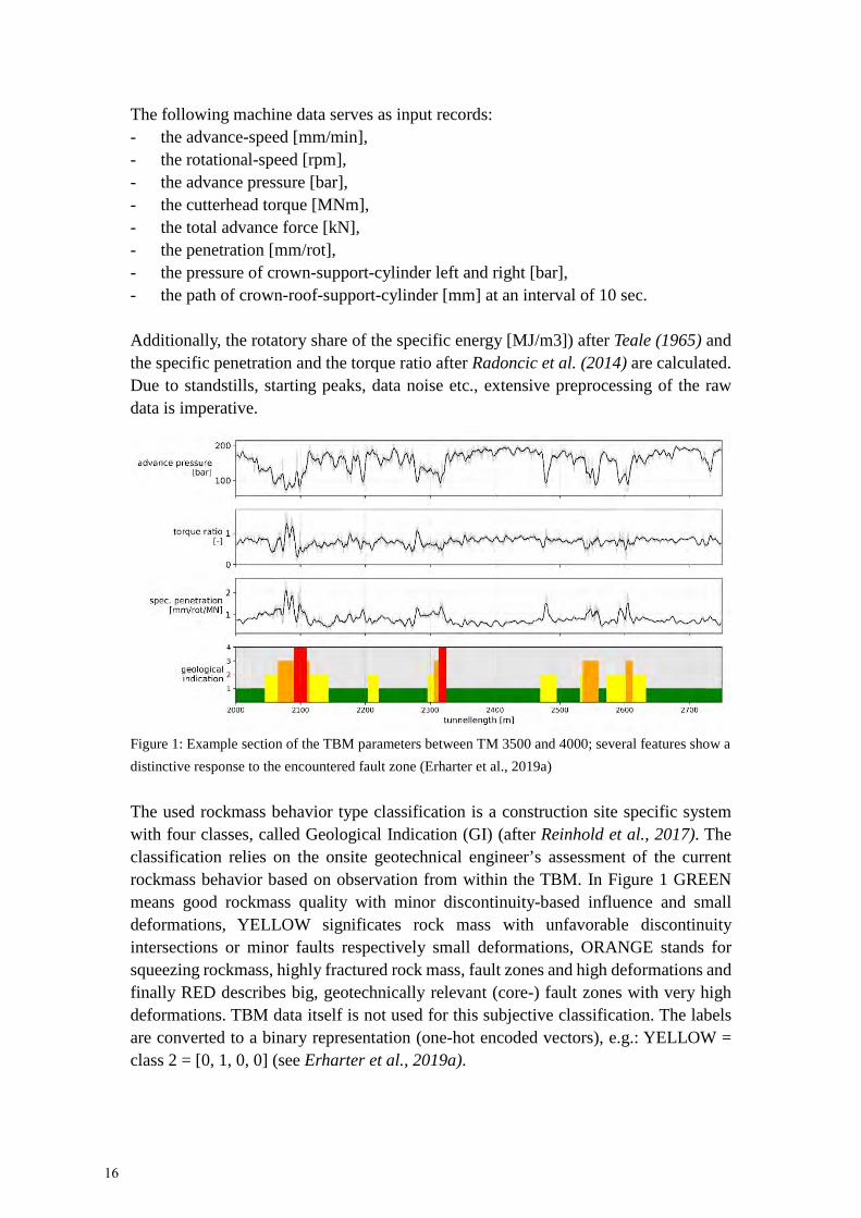
The following machine data serves as input records: - the advance-speed [mm/min],- the rotational-speed [rpm],- the advance pressure [bar],- the cutterhead torque [MNm],- the total advance force [kN],- the penetration [mm/rot],- the pressure of crown-support-cylinder left and right [bar],- the path of crown-roof-support-cylinder [mm] at an interval of 10 sec.
Additionally, the rotatory share of the specific energy [MJ/m3]) after Teale (1965) and the specific penetration and the torque ratio after Radoncic et al. (2014) are calculated. Due to standstills, starting peaks, data noise etc., extensive preprocessing of the raw data is imperative.
Figure 1: Example section of the TBM parameters between TM 3500 and 4000; several features show a distinctive response to the encountered fault zone (Erharter et al., 2019a)
The used rockmass behavior type classification is a construction site specific system with four classes, called Geological Indication (GI) (after Reinhold et al., 2017). The classification relies on the onsite geotechnical engineer’s assessment of the current rockmass behavior based on observation from within the TBM. In Figure 1 GREEN means good rockmass quality with minor discontinuity-based influence and small deformations, YELLOW significates rock mass with unfavorable discontinuity intersections or minor faults respectively small deformations, ORANGE stands for squeezing rockmass, highly fractured rock mass, fault zones and high deformations and finally RED describes big, geotechnically relevant (core-) fault zones with very high deformations. TBM data itself is not used for this subjective classification. The labels are converted to a binary representation (one-hot encoded vectors), e.g.: YELLOW = class 2 = [0, 1, 0, 0] (see Erharter et al., 2019a).
16

Subsequent results show the outcome of using Long-Short-Term Memory (LSTM)-network (Hochreiter et al., 1997) which are trained to automatically classify the TBM data. For details see Erharter et al. (2019a). Fig. 2 shows a result for TM 1000-2000. The data of 10000 tunnel meter have been used as training. In the upper row the TBM data (normalized torque ratio) is given, the second row shows the “ground truth” (=human classification) and the third row shows the respective categorical classification of the LSTM network. The direct output of the last layer (i.e. a probability value for each individual class) is given in the fourth row and can be seen as an indication of how “sure” the model is about its classifications.
Figure 2: LSTM-network classification of TM 1000 - 2000 (Erharter et al., 2019a)
The test set shows that satisfying accuracies as well as a good accordance between the ANN- and the human rock mass behavior classification can be achieved. Whereas the categorical classification makes the output directly comparable to the human classification, more information can be gathered from the probability values that result from the ANN’s direct output. Even if a sample’s classification is wrong in categorical terms, the relative output still gives an indication about the occurrence of other possible classes (more details see Erharter et al., 2019a).
17

References
Bergmeister, K., Reinhold, C. (2017), “Learning and optimization from the exploratory tunnel - Brenner Base Tunnel”, Geomechanics and Tunneling 10, Nr. 5, S. 467–476.
Erharter, G. H., Marcher, T. and Reinhold, C. (2019a), “Comparison of artificial neural networks for TBM data classification”, Proceedings of the 14th International Congress on Rock Mechanics and Rock Engineering (ISRM 2019), Rock Mechanics for Natural Resources and Infrastructure Development. Foz de Iguassu, Brazil, September 13 – 18, 2019.
Erharter, G. H., Marcher, T. and Reinhold, C. (2019b), “Artificial Neural Network based Online Rockmass Behavior Classification of TBM Data”, Proceedings of the 3rd International Conference on Information Technology in Geo-Engineering (ICITG 2019), Guimarães, Portugal, 29.09.2019 - 02.10.2019, Springer.
Erharter, G. H., Marcher, T. and Reinhold, C. (2019c) “Application of Artificial Intelligence for Underground Construction Chances and Challenges: Insights from the BBT exploratory tunnel Ahrental Pfons”, Geomechanics and Tunneling, in press.
Hinton, G., Deng, L., Yu, D., Dahl, G., Mohamed, A.-r., Jaitly, N., Senior, A., Vanhoucke, V., Nguyen, P., Sainath, T. and Kingsbury, B. (2012), “Deep neural networks for acoustic modeling in speech recognition”, IEEE Signal Processing Magazine, No. 29, pp. 82–97.
Hochreiter, S. and Schmidhuber, J. (1997), “Long Short-Term Memory”, Neural Computation, No. 9, pp. 1735–1780.
Marcher T (2019), “Long infrastructure tunnels – future trends and challenges”, ASEM19/ICTUS19 conference ― Invited Keynote Lecture, JeJu Southkorea.
Radoncic, N., Hein, M. and Moritz, B. (2014), “Determination of the system behaviour based on data analysis of a hard rock shield TBM / Analyse der Maschinenparameter zur Erfassung des Systemverhaltens beim Hartgesteins-Schildvortrieb”, Geomechanics and Tunneling, Vol. 7 No. 5, pp. 565–576.
Raschka, S. (2017), “Python machine learning: Machine learning and deep learning with Python, scikit-learn, and TensorFlow, Community experience distilled”, Second edition, fully revised and updated, Packt Publishing, Birmingham, UK.
Reinhold, C., Schwarz, C., Bergmeister, K. (2017), “Development of holistic prognosis models using exploration techniques and seismic prediction”, Geomechanics and Tunneling 10, Nr. 6, S. 767–778.
Teale, R. (1965), “The concept of specific energy in rock drilling”, International Journal of Rock Mechanics and Mining Sciences & Geomechanics Abstracts, Vol. 2 No. 2, p. 245.
18

Computational Modelling of Freezing Soils including Creep
R. J. Williams M., G. Meschke Structural Mechanics, Ruhr-Universität Bochum, Germany
Computational modelling of freezing soils represents a challenge due to the complex interactions between the creep-active behavior of frozen soil and the hydro- thermal interactions between the frozen and unfrozen surrounding soil. In this work, the frozen wall problem is analyzed first as a coupled T-H-M problem including primary creep effects to study the influence of the ice formation on the subsurface settlement. The set-up of the model is characterized by homogeneous geomechanical properties and pressure boundary conditions leading to a ground water inflow from one side. The evolution of ice formation and surface settlements is investigated (see Figure 1). In a second example, the frozen soil model is used in conjunction with a tunnel
Figure 1: Temperature and ice saturation of the frozen wall after 5 and 203 days
5.33 days
202.5 days
Temperature distribution Ice saturation and deformation due ice formation
19


Automated Modeling and Analysis Platform of Shield Tunnel Structures based on Independent Cover Meshless Method
Y. Gou, P. Yan, Y. Hong, Y. CaiGeotechnical Engineering, Tongji University, China
In the analysis and design of shield tunnel structures, conventional solid finite element models in two-dimension or three-dimension are used. As a method based on continuum mechanical deformation analysis, the finite element method (FEM) requires independent nodes and meshes on both sides of the contact surface when dealing with the discontinuous displacement existing at the joint of segments and the constraint between the segment and the bolt/bar, to ensure the independent meshing process of each components, without the embedding and overlap of grids. Meanwhile, rod elements are used to simulate the bolts and the bars, and they must be set straight at the nodes of corresponding solid elements. The meshing process can be very cumbersome. Shape function interpolating of the field variables in the domain based on discrete nodes is the core of the meshless method (MM). This idea simplified the labor-consuming meshing process in the FEM. Cai et al. proposed the Independent Cover Meshless Method (ICMM), by replacing the joint elements at the contact surface with Goodman elements, it is convenient to transit from continuous deformation analysis to discontinuous deformation analysis, just need to ensure the joint of the segment is located on the line of the nodes connection, without separate meshing of each components. Also, it’s easy to interpolating the displacement of arbitrary points inside the domain, thus awareness of the nodes and grids when inserting bolts and bars. This dramatically decrease the cost of meshing compared to the FEM. In this paper, the ICMM theory with lower meshing requirements is taken as the core analysis program, and a two dimensional (2D) analysis module of shield tunnel structure is developed. A 2D circular shield model is created and meshless discrete nodes with second-order displacement approximation are used to simulate the concrete. Rod elements and Goodman elements are respectively introduced to simulate the bars/bolts and the contact surface of segment joints. Based on PyQt5 and Python, a 2D automated modeling platform of shield tunnel is built, realizing the 2D interface design and data input function, and references the ICMM analysis program to realize segment internal force calculation, steel stress calculation and post-processing display etc., complete the 2D automatically modeling and analysis of shield tunnel structures.
21
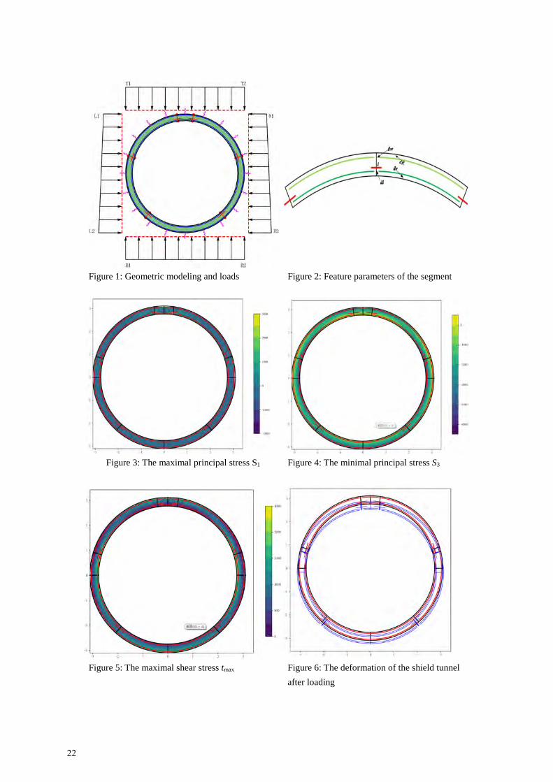
Figure 1: Geometric modeling and loads Figure 2: Feature parameters of the segment
Figure 3: The maximal principal stress S1 Figure 4: The minimal principal stress S3
Figure 5: The maximal shear stress tmax Figure 6: The deformation of the shield tunnel after loading
22

Seismic Response of Subway Station in Soft Soil: Shaking Table Testing versus Numerical Analysis
W. Wu, S. Ge, Y. Yuan, W. DingGeotechnical Engineering, Tongji University, China
A series of large scale shaking table tests were carried out at Tongji University in Shanghai, to investigate the response of a typical two-story three-span box type subway station in Shanghai embedded in soft soil under synthetic and recorded seismic excitation. Experimental results were analyzed in the aspects of acceleration of soil and structure, earth pressure and structural internal force. The system was then analyzed using full dynamic time history analyses at model scale by means of rigorous finite element models with modified kinematic hardening constitutive model. The constitutive model was calibrated after the laboratory element test and validated by back analysis of tests. The numerical predictions were compared with experimental data. The validated numerical models were then employed to further investigate the seismic response of station at prototype scale. The results of shaking table testing are thus indirectly converted (extrapolated) to real scale. Results indicate the racking deformation (story drift) of the box type station structure under transverse seismic motion. Residual earth pressure and surface settlement were observed.
Figure 1: Time history of experimental dynamic earth pressures recorded at three points towards the model tunnel structure sidewall
23


Infiltration Behavior of Bentonite Slurry into GranularSoils ─ Experimental Investigation and AnalyticalModels’ Evaluation
P. Mianji, W. Baille, T. Wichtmann
Soil Mechanics, Foundation Engineering and Environmental Geotechnics,
Ruhr-Universität Bochum, Germany
Slurry-supported shields became a common method in mechanized tunneling, mainly
in saturated granular soils. The bentonite slurry is pressurized toward the working face
to provide the required support pressure. The effective transfer of the applied pressure
depends on the mechanism of infiltration. In general terms, three mechanisms of
infiltration can be imagined, as illustrated in Fig.1 for the three mechanisms (a) outer
filter cake formation (I), (b) pure slurry penetration (II), and (c) combined penetration
and filter cake formation (inner and outer cake) (III). In the present work different
analytical approaches for time-dependent infiltration behavior of bentonite slurry into
granular soil were compared to experimental results from column tests. The
mechanical and hydraulic soil parameters needed for the models as the input data
were obtained through laboratory tests, i.e. rheological tests, and infiltration tests.
Figure 2, as an example, shows a prediction of the time-dependent infiltration
according to Anagnostou and Kovari (1994) compared to experimental results, for
all the three infiltration mechanisms. The comparison shows that the analytical
model satisfactorily predicts the time-dependent penetration of slurry in the case
mechanisms I and II, whereas there are discrepancies for mechanism III.
Figure 1: Infiltration mechanisms of bentonite slurry into granular soil
Figure 2: Comparison of analytical approach of Anagnostou & Kovari, 1994 to experiment results
0
20
40
60
80
100
120
140
0 50000 100000 150000
Invas
ion
dep
th [
mm
]
Time [s]
Experiment
Prediction0
200
400
600
800
1000
0 1000 2000 3000
Time [s]
Experiment
Prediction0
20
40
60
80
100
120
140
0 1000 2000 3000
Time [s]
ExperimentPrediction
(I) (II) (III)
(a) (b)
(c)
25


Artificial Test Samples to Simulate "Soft Rock Anisotropy"
M. Winkler, T. MarcherRock Mechanics and Tunnelling, Graz University of Technology, Austria
The development of advanced constitutive models for the simulation of practical boundary value problems (BVPs) requires a deep understanding of the mechanical behavior of the materials under investigation. This especially applies to the more and more complex geology, the corresponding ground materials respectively, that future underground construction works will have to be carried out in. A proper model calibration in connection with the simulation of such complicated materials, including soft anisotropic rock, is crucial and a detailed study of the behavioral mechanisms under different boundary conditions is a fundamental requirement.
Behavioral material mechanisms are usually studied from the performance of mainly destructive laboratory tests, e.g. UCS and triaxial tests. However, natural samples of soft anisotropic rock always include inherent inhomogeneities and sample disturbances, caused by the sampling procedure itself. This complicates the acquisition of clear statements about the influence of independent variables on the material`s mechanical behavior. Apart from sample quality, another problem with retrieving natural soft rock samples is associated with the high costs of the sampling procedure and the limited amount of available specimens for testing. Due to these major constraints our current research focuses on finding suitable modelling materials for soft anisotropic rocks, to facilitate an economical investigation of their mechanical behavior under different boundary conditions.
The general idea of replicating natural materials, including soft rocks, is not new to the rock mechanics community. As reported in literature, various kinds of modelling materials for the imitation of the mechanical behavior of different rock types have already been examined. One of the most comprehensive reviews about synthetic rock modelling materials is given by Stimpson (1970). He presented a general classification scheme for different modelling materials, such as plaster, cork, concrete, rubber, plastics and gelatins, among others, and discussed their suitability for the purpose of replicating rock. Johnston und Choi (1986) blended mudstone powder with cementing agents and calcium chloride as a setting accelerator and developed a homogeneous and isotropic synthetic soft rock, known as Johnstone, to simulate naturally occurring mudstones. Their manufacturing technique included an accelerated repetition of the geological processes involved in the formation of the natural rocks in terms of consolidating the samples by applied compression. In Indraratna (1990) some general considerations for the choice of a suitable modelling material are provided – among other requirements, the material should consist of constituents which are non-toxic and universally available; the mechanical properties of the specimens must be reproducible
27

and the samples should be easily manufactured under laboratory conditions; the physical properties of the samples should not be time-dependent nor sensitive to temperature and humidity. The research of Indraratna (1990) aimed at finding a suitable modelling material for the simulation of a variety of different sedimentary rocks, such as limestone, sandstone and shale. A mix of hydrocal white gypsum cement, fine uniform sand, water and anhydrous sodium phosphate (retarder) proved to satisfy the established criteria. Another synthetic modelling material for soft rock by Mei et al. (2017) was composed of cement, plaster, medium sand and concrete hardening accelerator. By using different constituent ratios the mixes displayed a uniaxial compressive strength in the range of 0.85 – 3.80 MPa, a deformation modulus E50 between 108 and 560 MPa and a failure strain range of 0.8 – 1.3 %. Excellent work with respect to simulating cross-anisotropic sandstones and shales has been carried out by Tien and Tsao (2000). They manufactured samples of alternating layers (1.75 – 2 mm in thickness) from cementicious materials with different initial strength and stiffness properties. Tien et al. (2006) improved the manufacturing technique of cross-anisotropic samples by slicing plates from blocks of two different materials and assembling them on a building platform with the aid of vacuum lifters. Having collected information from literature, the material requirements on our own soft anisotropic rock simulants were defined as follows:
a) Compressive strength: 1 – 20 MPa b) Insensitivity to climatic conditions c) High degree of reproducibility d) Easy to manufacture e) Universally available constituents
Figure 1: Compaction of a cylindrical test sample using a vibrating table Before dealing with anisotropy and a layered composition it was decided to study and improve the behavior of homogenous mixes. Referring to German Standard DIN 1053 – 1 five different mixtures composed of hydrated lime, cement CEMII-B 32.5R and
28

fine sand ( 0 - 1 mm), as commonly used in masonry works, were prepared with varying constituent ratios and w/b-ratios to yield good workability. Cylindrical single-use molds made from polystyrene and a diameter/height-ratio of 100 mm/ 140 mm were employed for sample manufacturing. The compaction of samples, subsequently used for compressive strength testing, was carried out in up to 4 layers with the aid of a small vibrating table (Figure 1). The samples were then cured in the basement of the laboratory at a temperature of around 20°C and a relative humidity varying between 70 and 80°C. Samples with higher cement contents were further kept in plastic bags for 7 days, as suggested by ÖNORM-EN 1015-11, to prevent them from drying too quickly. Beside samples for UCS testing, PLT test samples were manufactured from each mix. First UCS tests performed on different specimens after 28 days of curing time delivered evidence, confirming the applicability of lime-cement based mortars for the simulation of natural anisotropic soft rocks. The received compressive strength values, within a range of 0.271 – 8.403 MPa, met the defined requirements. Also the PLT tests could be performed satisfactorily and all samples failed in a brittle manner. The received correlation factor c, that correlates the 𝐼𝐼𝑠𝑠 value to the compressive strength, was determined with a value of around 7.3.
Figure 2: Axial Stress-Strain curves from compressive strength tests on samples with different ratios of lime : cement : sand – increasing cement contents yield a higher compressive strength Further steps to be taken with respect to the present research topic include the improvement of the material’s wet properties (self-compaction and increased bleeding resistance) in a way that they allow the production of a layering. Furthermore, the anisotropic effect from the addition of aligned fibers to the homogeneous mixes will be investigated and the use of modern 3D printing techniques for the purpose of producing soft anisotropic rock simulants will be tested.
29

References
1996-1: DIN 1053-1:1996-11. Indraratna, B. (1990): Development and applications of a synthetic material to
simulate soft sedimentary rocks. In: Géotechnique 40 (2), S. 189–200. DOI: 10.1680/geot.1990.40.2.189.
Johnston, I. W.; Choi, S. K. (1986): A synthetic soft rock for laboratory model studies. In: Géotechnique 36 (2), S. 251–263. DOI: 10.1680/geot.1986.36.2.251.
Mei, Can; Fang, Qing; Luo, Haowei; Yin, Jiangang; Fu, Xudong (2017): A Synthetic Material to Simulate Soft Rocks and Its Applications for Model Studies of Socketed Piles. In: Advances in Materials Science and Engineering 2017 (2), S. 1–8. DOI: 10.1155/2017/1565438.
ÖNORM EN 1015-11: 2018 01 01.
Stimpson, B. (1970): Modelling materials for engineering rock mechanics. In: International Journal of Rock Mechanics and Mining Sciences & Geomechanics Abstracts 7 (1), S. 77–121. DOI: 10.1016/0148-9062(70)90029-X.
Tien, Yong Ming; Kuo, Ming Chuan; Juang, Charng Hsein (2006): An experimental investigation of the failure mechanism of simulated transversely isotropic rocks. In: International Journal of Rock Mechanics and Mining Sciences 43 (8), S. 1163–1181. DOI: 10.1016/j.ijrmms.2006.03.011.
Tien, Yong Ming; Tsao, Po Fong (2000): Preparation and mechanical properties of artificial transversely isotropic rock. In: International Journal of Rock Mechanics and Mining Sciences 37 (6), S. 1001–1012. DOI: 10.1016/S1365-1609(00)00024-1.
30

Notes

WWW.RUB.DE /SFB837WWW.RUB.DE /SFB837WWW.RUB.DE /SFB837WWW.RUB.DE /SFB837WWW.RUB.DE /SFB837WWW.RUB.DE /SFB837TWWW.RUB.DE /SFB837TWWW.RUB.DE /SFB837UWWW.RUB.DE /SFB837UWWW.RUB.DE /SFB837NWWW.RUB.DE /SFB837NWWW.RUB.DE /SFB837NE
LING
MECHAN
WWW.RUB.DE /SFB837N
WWW.RUB.DE /SFB837IWWW.RUB.DE /SFB837IWWW.RUB.DE /SFB837ZWWW.RUB.DE /SFB837ZWWW.RUB.DE /SFB837EWWW.RUB.DE /SFB837EWWW.RUB.DE /SFB837DWWW.RUB.DE /SFB837DWWW.RUB.DE /SFB837
MODELINGINTERA
CTION
SFB 837 - Interaction Modeling in Mechanized Tunneling
Fon: +49 (0)234 32-24759Fax: +49 (0)234 32-14696Mail: [email protected]
CEO: Dipl.-Ing. Jörg Sahlmen
Building IC/6/89 Universitätsstraße 150 D-44801 Bochum
RUHR UNIVERSITY BOCHUM
3